barging around london
TRANSCRIPT

1
Barging around London A thesis submitted for the degree of Masters of Science in
Naval Architecture by
Henrik Utvik, B. Sc.
Department of Mechanical Engineering,
University College London
I confirm that this is all my own work
Total number of words: 8,740

2
ABSTRACT The canals around London provides excellent opportunities for companies around the city to have
goods delivered by water all the way to their doorstep. However, inland waterways transport has
not been utilized in London to any significant degree for half a century.
This paper deals with a cutting edge canal freight vessel designed especially for London. The barge is
self-propelled, and maximised in size in order to exploit the mass-transport market. The vessel
utilizes a high-temperature fuel cell, allowing the city to have a virtually noise-free and emissions-
free mass-transport alternative, as well as being fuel-flexible, thus versatile in the market. The cargo-
hold is designed to take a wide range of loads, in order to accommodate a wide variety of customer
demands, and maximise the utilization of the vessel. The barge is equipped with a crane which
allows it to drop off various cargo types at any drop-off point in the city.
The paper argues that the vessel can be competitive with road-based transport in the long run. If the
design is put into operation, it can have several utilitarian benefits for the city, including:
Significantly cut air and sound pollution.
Contribute to a lower carbon-footprint for the city.
Take traffic off the roads, thus increasing safety.

3
Contents
List of tables ............................................................................................................................................ 5
List of figures ........................................................................................................................................... 6
1. Introduction .................................................................................................................................... 7
1.1 Aims ........................................................................................................................................ 7
1.2 Canal properties ..................................................................................................................... 7
2. Design philosophy and background ............................................................................................... 8
2.1 State of the art ............................................................................................................................. 8
2.2 Rules ........................................................................................................................................... 10
2.3 Public initiatives and plans ........................................................................................................ 10
2.4 Design methodology .................................................................................................................. 10
3 Concept design ............................................................................................................................. 13
3.1 Design problems ................................................................................................................... 13
3.2 Outline requirements ........................................................................................................... 15
3.3 Payload types and vessel role .............................................................................................. 15
3.4 Vessel types .......................................................................................................................... 17
3.4.1 Dumb barge with tug boat ........................................................................................... 17
3.4.2 Articulated and integrated tug-barge .......................................................................... 18
3.4.3 Self-propelled barge ..................................................................................................... 18
3.4.4 Discussion ..................................................................................................................... 18
3.5 Design considerations .......................................................................................................... 18
3.6 Hull design and resistance ................................................................................................... 19
3.6.1 Initial sizing ................................................................................................................... 19
3.6.2 Hull design .................................................................................................................... 20
3.6.3 Hydrostatic data ........................................................................................................... 21
3.6.4 Squat ............................................................................................................................. 22
3.6.5 Resistance calculations ................................................................................................ 22
4 Detailed design ............................................................................................................................. 23
4.1 Propulsion ............................................................................................................................. 23
4.1.1 Introduction .................................................................................................................. 23
4.1.2 Literature review .......................................................................................................... 24
4.1.3 Discussion ..................................................................................................................... 27
4.1.4 Conclusion .................................................................................................................... 29
4.2 Propeller system ................................................................................................................... 30
4.2.1 Defining user requirements ......................................................................................... 30
4.2.2 Design Process .............................................................................................................. 30
4
4.2.3 Conclusion .................................................................................................................... 31
4.3 General arrangement ........................................................................................................... 31
4.3.1 Explanation ................................................................................................................... 31
4.3.2 Sizing ............................................................................................................................. 33
4.4 Structure ............................................................................................................................... 34
4.4.1 Modelling and assumptions ......................................................................................... 34
4.4.2 Analysis ......................................................................................................................... 34
4.4.3 Conclusion .................................................................................................................... 36
4.5 Stability and operations ....................................................................................................... 37
4.5.1 Introduction .................................................................................................................. 37
4.5.2 Transverse stability ...................................................................................................... 38
4.5.3 Longitudinal stability .................................................................................................... 39
4.5.4 Conclusion .................................................................................................................... 39
5 Finalised concept .......................................................................................................................... 40
5.1 Logistics ................................................................................................................................. 40
5.1.1 Fuelling .......................................................................................................................... 40
5.1.2 Canals capacity ............................................................................................................. 40
Vessel types ..................................................................................... Error! Bookmark not defined.
5.2 Economics ............................................................................................................................. 41
5.2.1 Procurement cost ......................................................................................................... 41
5.2.2 Through-life costs ......................................................................................................... 41
5.3 Emerging technologies ......................................................................................................... 42
5.4 Business model ..................................................................................................................... 44
6 Conclusions ................................................................................................................................... 45
6.1 Summary ............................................................................................................................... 45
6.2 Further work ......................................................................................................................... 46
Works Cited ........................................................................................................................................... 46
APPENDIX A: FUEL USAGE, MASS AND VOLUME CALCULATIONS ........................................................ 47
APPENDIX B: COST ................................................................................................................................ 48
APPENDIX C: STRUCTURES .................................................................................................................... 49
APPENDIX D: STABILITY THEORY ........................................................................................................... 51

5
List of tables Table number
Title Page number
1 Grand Union Canal main locks 7
2 Adjacent Canal Arms Main Locks 7
3 Proposed user--requirements 14
4 Analysis of dumb barge 17
5 Analysis of ATB 18
6 Analysis of self-propelled barge 18
7 Yearly freight potential scenario 19
8 Yearly freight at varying capacities 19
9 Parametric survey 20
10 Main dimensions 20
11 Hydrostatic data 22
12 Squat at varying speeds 22
13 Power table, effective power 23
14 Advantages and disadvantages of fuel cells 24
15 PEM fuel cells 25
16 SO fuel cells and MC fuel cells 25
17 Alkaline fuel cells 26
18 Advantages and disadvantages of batteries 26
19 Lead-acid batteries 27
20 Li-ion batteries 27
21 Prime mover sizing scenario 28
22 Weight and centres 33
23 Initial design bending moments 34
24 Required section modulus, example. 34
25 Scantlings, example 35
26 Lightship weight and centres development 36
27 Deadweight weight and centres development 36
28 Weights and centres, updated 37
29 Cargo densities 37
30 Load-cases 38
31 Crane limitations 38
32 Longitudinal load-plan 39
33 Cost-estimate 40
34 Gains from no-manning 42
35 Challenges with no-manning 42
36 Risks with no-manning 43
37 Business model 43

6
List of figures Figure number
Title Page number
1 Canals map 8
2 List of technology innovations 9
3 Scenario for emission reductions 10
4 Bow comparison 21
5 Rendering of concept 21
6 Power curve, effective power 23
7 All—electric propulsion scenario 24
8 Energy density comparison 28
9 Power density comparison 29
10 Procurement cost comparison 29
11 Installed power 30
12 13
Skewed propeller General arrangement
31 31
14 Articulating crane 32
15 Iterative structural procedure 35
16 GM, varied loads 38
17 Capacity scenario, Slough arm 40
18 Yearly cost per barge 41
19 SWOT-analysis 44
Nomenclature IWW – Inland waterways
ATB – Articulated tug-barge
HTPEMFC – High temperature proton exchange membrane fuel cell
LTPEMFC – Low temperature proton exchange membrane fuel cell
SOFC – Solid-oxide fuel cell
MCFC – molten carbonite fuel cell
AFC – Alkaline fuel cell
CP-PROPELLER – Controllable pitch-propeller
FP-PROPELLER – fixed pitch-propeller

7
1. Introduction
1.1 Aims The Grand Union Canal in London has existed since the early 19th century. While well-utilized from
the mid-19th century onwards, traffic on the canals steadily declined as rail transport became
increasingly cost-efficient and prevalent around the country. This was because railroad steam
engines became cheaper and faster due to coal-mining in the West. Commercial traffic was entirely
discontinued in the 1950s, but has seen limited attempts at revival in the past couple of decades.
This comprises waste management and some supply shipping into Park Royal.
This paper deals with how the canals can be utilized today, and how cutting edge innovations can be
applied in order to create a barge fleet for the future of London. Important discussion points include:
- The proposal and design of a ship concept to operate on the London canals, particularly with
regards to the Slough Arm, which includes a high number of companies along its line.
- Important considerations with regards to operations and market potential.
- Emerging opportunities and future scenarios.
1.2 Canal properties The following is a general description of the canals. The main restrictions on dimensions are due to
locks. Additionally, there are maximum height limitations due to bridges.
Grand Union Canal Main Locks
Section Length Beam Height (above waterline) Draught
Regents 21.95 4.2 2.28 1.06
Paddington arm 21.95 4.2 2.28 1.06
Main line 21.95 4.2 2.28 1.06
Slough arm 21.95 4.2 2.28 1.06
Table 1: Grand Union Canal main locks
Adjacent Canal Arms Main Locks
Canal arm Length Beam Height (above waterline) Draught
Hertford Union 21.95 4.2 2.28 1.06
Lee - Thames 26.82 5.8 2.05 2.05
Lee - Old Ford 26.82 5.5 2.05 1.06
Lee - Ponders End 25.9 4.8 2.05 1.06
Table 2: Adjacent Canal Arms Main Locks
The Regents Canal has a length of around 13.6 kilometres (PBA, 2007). The Slough Arm has a length
of around 42 kilometres (Partnership, Park Royal, 2007). The width of the canal itself is highly
variable, ranging from around 6 to around 15 meters. According to the London Freight Group, the
navigational depth is varying, but can be taken to be around 1.5 meters.

8
Figure 1: London canals (British Waterways).
2. Design philosophy and background
2.1 State of the art (Hekkenberg, Tugt, Till, & Zanden, 2007) postulates that the rate of technological innovation in
inland waterways (IWW) shipping is considered to be low. The main reasons for this are cited to be
the following:
1. Inland waterways vessels are usually operated by small companies with little extra capital to
bear the risks associated with new technologies.
2. Due to the nature of inland vessels being of relatively low value, the technology often needs
to be proven to be considerably better than the already used alternatives for the investment
to be worth it.
3. Researchers often consider problems in inland waterways to be of relatively low complexity,
and thus not worth pursuing.
4. Brokers usually interested in selling standardised products instead of designs optimised for a
specific role.
A number of design challenges are cited for IWW vessels in particular. One is restrictions on
dimensions due to locks, bridges etc. This limits the payload of each vessel. Cited as more important
is variety in water-depth that can be encountered. The limited depth and the potential great depth-
variety (due to factors such as weather), makes it difficult to design for one optimal operational
profile (Authors note: This is mainly cited as a problem in rivers, but might be prevalent in the
London canals as well depending on how often/if the canals are dredged).
In conclusion, all innovation in inland waterways are both driven and restricted by the
aforementioned challenges. This affects all major ship design disciplines in various ways.
Basic design: Finding ways to optimise space within the ship limits.
Hydrodynamics: Finding the right compromise between resistance-optimisation and
displacement. Also minimising shallow water and other typical inland waterways effects.
Power systems: Optimising power supply for widely varying working environments.
To meet this challenges, it is suggested that researchers, industry, and legislators need to cooperate
closely to accelerate the various modes of the process.
9
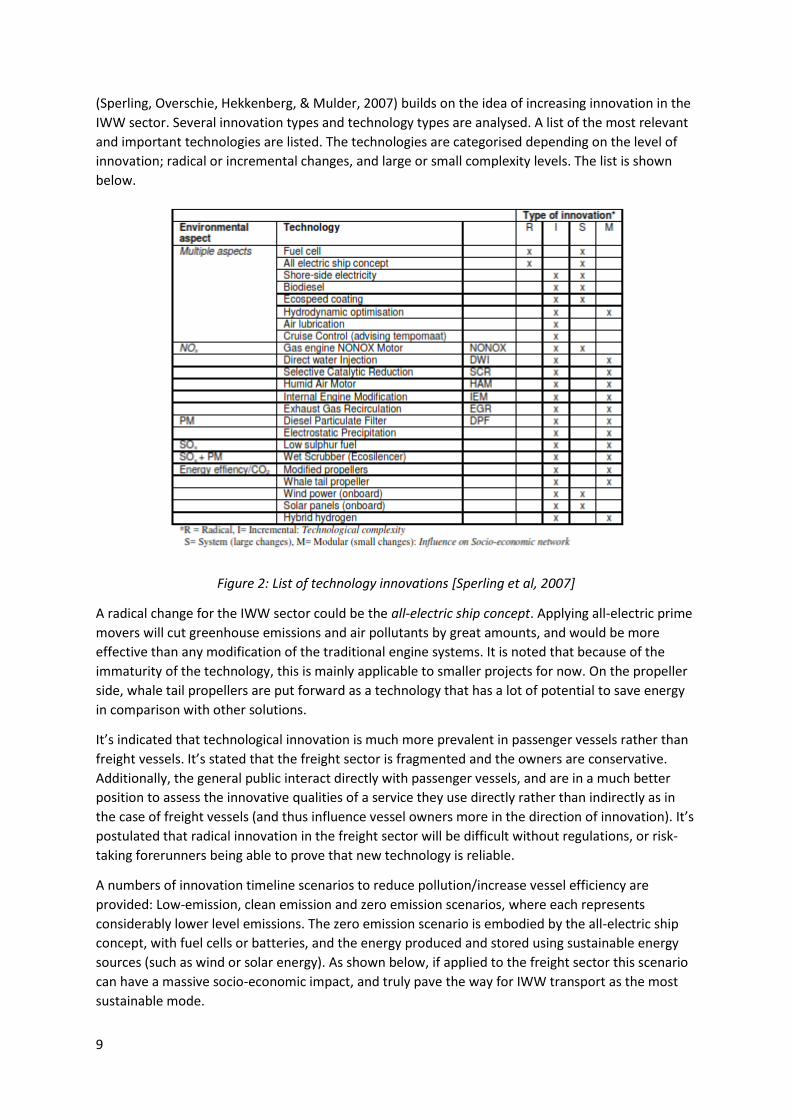
(Sperling, Overschie, Hekkenberg, & Mulder, 2007) builds on the idea of increasing innovation in the
IWW sector. Several innovation types and technology types are analysed. A list of the most relevant
and important technologies are listed. The technologies are categorised depending on the level of
innovation; radical or incremental changes, and large or small complexity levels. The list is shown
below.
Figure 2: List of technology innovations [Sperling et al, 2007]
A radical change for the IWW sector could be the all-electric ship concept. Applying all-electric prime
movers will cut greenhouse emissions and air pollutants by great amounts, and would be more
effective than any modification of the traditional engine systems. It is noted that because of the
immaturity of the technology, this is mainly applicable to smaller projects for now. On the propeller
side, whale tail propellers are put forward as a technology that has a lot of potential to save energy
in comparison with other solutions.
It’s indicated that technological innovation is much more prevalent in passenger vessels rather than
freight vessels. It’s stated that the freight sector is fragmented and the owners are conservative.
Additionally, the general public interact directly with passenger vessels, and are in a much better
position to assess the innovative qualities of a service they use directly rather than indirectly as in
the case of freight vessels (and thus influence vessel owners more in the direction of innovation). It’s
postulated that radical innovation in the freight sector will be difficult without regulations, or risk-
taking forerunners being able to prove that new technology is reliable.
A numbers of innovation timeline scenarios to reduce pollution/increase vessel efficiency are
provided: Low-emission, clean emission and zero emission scenarios, where each represents
considerably lower level emissions. The zero emission scenario is embodied by the all-electric ship
concept, with fuel cells or batteries, and the energy produced and stored using sustainable energy
sources (such as wind or solar energy). As shown below, if applied to the freight sector this scenario
can have a massive socio-economic impact, and truly pave the way for IWW transport as the most
sustainable mode.

10
Figure 3: Scenario for emission reductions [Sperling et al 20007]
2.2 Rules For inland waterways vessels operating in the UK, the MGN 280 code applies for operations,
structures, stability, and manning.
2.3 Public initiatives and plans The EU in particular is pushing for increased usage of the inland waterways as a means to achieving
more sustainable transport of goods around the continent, and regulations to incentivise and
facilitate more inland waterways transport is continuously being investigated. The goal of these
policies is to increase the share of inland waterways transport to 20 % of total goods transported in
the EU by 2020 (UN, 2011).
There is currently not a comprehensive domestic plan in the UK for outmoding transport to the
inland waterways. However, the potential of the rivers and canals system are repeatedly recognised.
The previous government coalition proposed to create a public charity organization to operate and
upgrade the canals, but no fixed proposition seem to have emerged.
The London government has assessed the potential for waterways transport at several occasions,
but little has been done. A report in 2007 questioned the potential for the canals, which such
barriers as investment costs and no enthusiasm in the public brought up as points against their
usage (PBA, 2007).
2.4 Design methodology Because of the high number of variables and uncertainties prevalent in the early stages of product
design, engineering projects such as these are usually highly iterative. This is highly relevant for
maritime engineering projects.
Because of the inherent uncertainties in such a process it is prudent to formalise as much of it as
possible, and apply a rigorous design methodology. Since the project is both a research paper and a
concept design, the author will be working on the fringe between those two disciplines, combining
them where possible. Thus the following methodology will be applied:

11
1. Formulate design problems
Usually in a research paper the subject for research is outlined through one or several research
questions. Since this is essentially a design task, this will be done through more concrete design
problems instead.
The main design problems should summarise what the design is supposed be about – which needs it
addresses and the main design features that should be achieved. Every step in the design process
should be about answering these problems.
From the design problems should emerge a number of requirements for the design, and these will
have to be met for the design to be considered successful.
2. Base concept
A base concept should emerge at an early stage. The objective is to take the known restrictions and
requirements and obtain a more concrete model to be iterated upon. In the case of naval
architecture, this means making a solid model of the hull, and making stability and space estimates.
Also, the vessel role and size should be decided. This will make it easier to decide other unknowns
later in the design stage.
Input:
Design requirements.
Design restrictions.
Output:
Vessel role definition.
Size estimates.
Hydrostatic data.
Displacement estimates.
Total cargo volume estimates.
Resistance estimate.
Tools:
Hand sketches.
NA design program such as Maxsurf or Paramarine.
Spreadsheets.
3. Research
A detailed literature review into the various important aspects of the design will be performed. The
goal is to assess cutting-edge technology developments, and how such technologies can be
implemented in order to achieve the design requirements. The research is not about concrete
design, but learning about how people have applied new knowledge. The result should be to make
apparent the best available technologies for the defined requirements, and how to implement them
into the design.
Input:
12
Design requirements.
Output:
Detailed knowledge on how to answer design requirements.
Literature review document.
Tools:
UCL library services.
Online academic services such as Google Scholar and Elsevier.
High-knowledge personnel if obtainable.
4. Detailed design
At this stage, the research knowledge and base concept can be applied to achieve a detailed design.
This should consist of detailed recommendations and solutions on how to fulfil main design
requirements. Once the concept has been more refined, detailed technical data such as load
distributions, load cases, and structural data can be obtained.
Input:
Base concept.
Research output.
Output:
Detailed technical concept: Load cases, refined hydrostatic data, and structural analysis.
Solutions to main design requirements.
Tools:
Ship design and other software.
Literature review document.
5. Feasibility and economic studies
The economic sustainability and feasibility of the vessel must be emphasised and proven. A good
estimate of the equipment and build costs will be useful to potential investors. However, in order to
attract attention, a suitable business plan should also be presented, so that it can be shown the
numerous ways the ship could bring in money for the owner, and the special features of the vessel
that can be marketed to clients.
Input:
Some market analysis.
Design “wow-effect”, main sales arguments.
Structural data.
Output:
Procurement and through-life cost estimates.

13
Business-plan that captures main revenue streams from the ship, but also covers risk-
assessment and main challenges.
Tools:
Structural analysis.
A business plan methodology.
Industry data.
6. Communicating results
The results needs to be available to decision makers, researchers, investors, and the public in order
for the concept to gain wind and actually be taken to a more concrete level. Thus communicating the
results in a way that showcases the high technical knowledge achieved and applied, but is also
understandable to laymen, is paramount. Visualisations are important, such as sketches showcasing
the vessel interacting with the environment around the canals. Drafters and artists may be hired in
order to make system sketches.
Input:
The complete concept design.
Output:
Technical report.
Technical drawings.
Concept sketches.
Presentations.
Tools:
Drawing programs.
Sketching tools.
Presentation toolkits.
3 Concept design
3.1 Design problems In engineering design, it is imperative to have a solid understanding of customer needs. While
companies spend a lot of money on marketing, it is important not only to know what customers say,
but also what they think. Thus empathising with and mapping the perspective of users can be an
important design tool. This tool was applied in order to get a good grip on the relevant design
problems. This was again important to set good vessel requirements, which is the framework for a
good ship design.
In this case, the user-needs also reflect how the vessel has several direct and indirect user-groups, all
with different perspectives and requirements.

14
User group Mode of interaction Interests and needs Success criteria
Ship owner Responsible for operations and maintenance.
Responsible to customers.
Technological reliability.
Low-cost operations.
Marketable concept.
Low down-time and maximising vessel usage.
A sustainable and profitable service.
Crew Navigation.
Loading/unloading.
Hands-on maintenance.
On-board safety.
Simple operations.
Low noise and vibrations.
Enjoying working at the vessels.
The ability to perform vessel operations safely.
Customers Buying the services the barges can provide.
Deliveries on time.
Flexibility in service.
Simple and fast cargo-handling.
High reliability.
Competitive prices.
General public For the general public, the barges can potentially have utilitarian qualities that contributes to the greater good of the city.
Noise and air pollution considered a big problem in the city.
Traffic safety important, outmoding road transport considered beneficial.
Lower air pollution.
Less road-traffic and noise around London.
Table 3: Proposed user-requirements
1. How can emissions free navigation in London be made possible?
2. How can the vessel designs and fleet cope flexibly with changes in market conditions?
3. What is the most optimal loading system? How to design loading and cargo handling
systems that are congruous with the operations both on land and from the ship?
4. How will the ships navigate as safely as possible?
5. How can the design most effectively reduce noise?
6. What kind of infrastructure investments are necessary to sustain the operation?
These questions provide a framework for a set of requirements that the design should meet, which
are outlined in the next chapter.

15
3.2 Outline requirements Primary requirements
1. The hull dimensions will have to adhere to canal lock restrictions.
2. The vessel speed will adhere to the speed limit on London canals – up to 3.5 kts service
speed.
3. In order to create a truly environmentally sustainable alternative to road-based transport,
the ship will be zero-emissions.
4. In order to maximise commercial potential and usage of the vessel, and also in order to
make it versatile and competitive under changing commercial conditions over the ship life,
the vessel should have flexible capabilities for cargo handling and other systems.
Secondary requirements
1. The suggested propellers and propulsion system should minimise sound and disturbances to
the adjacent area.
2. To save costs, the ship will be designed for low manning, but will adhere to the minimum
crew limit as required by UK law and/or MCA regulations, if any.
3.3 Payload types and vessel role A more in-depth discussion on various categories of payload and their potential to bring in revenue
was explored more in detail. The goal was to make apparent which types of vessels that could be
designed, their respective commercial potential, and how to potentially combine roles.
Beverages and catering
Examples: Local craft beer, locally produced foods, supermarket goods.
Medium of cargo: Plastic containers, small portable plastic tanks, cardboard boxes and pallets.
Assessment of potential: Park Royal is known as “the food basket of London” because of its high food
production rates, and delivers food to many supermarkets and catering places in London.
Importantly, the Grand Union Canal goes right through it, which makes water-freight a very
convenient alternative for the businesses. There are also hundreds of larger and smaller breweries
all around London delivering beverages to local pubs. Additionally, water-freight could be used to
transport food supplies coming into London from around the country. An estimated 1/3 of all food
consumed in London is produced in Park Royal (The Daily Telegraph, 2012). Assuming each person in
London consumes on average 1.5 kg food and beverages a day, this adds up to approximately 1.6
million tonnes a year.
Industrial supplies
Examples: Raw materials, manufacturing equipment and equipment parts.
Medium of cargo: ISO-containers, crates, plastic containers, pallets, cardboard boxes.
Assessment of potential: Particularly relevant for supplies into Park Royal, which is the biggest
industrial park in Europe. The large volumes and weights possible to carry by barge makes water-
freight a versatile and reliable alternative to road transport.
Waste management and recycling
Examples: Sewage treatment, industrial waste, recycling of various goods such as bottles, cardboard,
plastic.

16
Medium of cargo: Tanks, plastic containers of various sizes.
Assessment of potential: Sewage and industrial waste transport already exists as a limited service on
the canals, but there is a potential to expand it. A 2007 study estimated a service of 15,000 tons per
annum could be started up with just a handful of companies that had expressed concrete interest,
but the service could potentially rise to 1.6 million tonnes a year depending on where the recycling
and waste centres are built (Partnership, Park Royal, 2007).
Construction supplies
Examples: Gravel, cement, asphalt materials, construction equipment.
Medium of cargo: Raw materials mainly in bulk. Other supplies in containers, crates and cardboard
boxes.
Assessment of potential: With the constant flow of new construction/maintenance/rebuilding
projects around the city, there is a high potential to outmode it from roads to water-freight. The
main sales points would be to provide a more reliable service, and also higher efficiency, since the
cargo transported by a few hundred lorries would only need a few trips with a few barges. Projects
with a range of 60,000-100,000 t of steel and gravel has been mentioned (Partnership, Park Royal,
2007).
Post and deliveries
Examples: Domestic deliveries of goods, such as online orders.
Medium of cargo: Mainly cardboard boxes.
Assessment of potential: The potential is very volume dependent, and it’s not evident that water-
freight can be a big competitor to road-deliveries in the short-term. However, it could appeal to
people living along or nearby the canals, where it could turn out to be more time-efficient. It could
also appeal to people wanting their goods delivered in the most sustainable manner possible.
Reliability would be an important sales point.
Passengers
Examples: Could be both events for tourists/visitors and an alternative to current TfL-services.
Medium of cargo: N/A.
Assessment of potential: Passenger vessels has potential both for tourists and commuters.
Commuters
Discussion
Considering the above options in cargo types, the following main types of vessels can be identified to
potentially make a difference for transport in London.
1. Bulk Cargo vessels transporting mainly construction and building materials, and perhaps to a
certain extent manufacturing materials.
2. Special cargo vessels transporting specialised cargos such as industrial waste, flammable
materials et.al. Likely to be a tanker or have mainly tanks as cargo holds.
3. General cargo vessels transporting anything that can be containerised.
4. Passenger vessels.
17
While passenger vessels are most likely to require their own sets of vessels, it could be possible to
combine the three first types of vessels into one. The main role is likely to be that of a general cargo
vessel, transporting cargo through mediums such as:
Plastic containers
Small plastic tanks
Cardboard boxes
Pallets
ISO containers
Crates
Recycling storage units
Other boxy cargo units
And, if allowable within existing rulesets, it could be easily converted into a bulk storage. This is likely
to require some special structural considerations. Additionally, large portable tanks could be a
potential cargo. This would combine the potential of several of the major
Servicing both the commercial sector, and possibly also domestic deliveries, the profile of the vessel
could be a "water-born lorry-service”. The main competitors would be “white vans”, lorries and
trailers. If it becomes a success, it could certainly help achieve the goal of more environmentally
friendly transport, and also reduce traffic around the main roads.
The main focus will be solid, containerised cargo, but analyses to see if it’s possible within existing
rules and regulations to also extend to large, portable tanks will be performed.
3.4 Vessel types
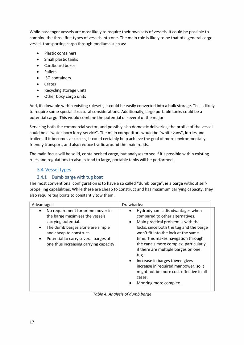
3.4.1 Dumb barge with tug boat The most conventional configuration is to have a so called “dumb barge”, ie a barge without self-
propelling capabilities. While these are cheap to construct and has maximum carrying capacity, they
also require tug boats to constantly tow them.
Advantages: Drawbacks:
No requirement for prime mover in the barge maximises the vessels carrying potential.
The dumb barges alone are simple and cheap to construct.
Potential to carry several barges at one thus increasing carrying capacity
Hydrodynamic disadvantages when compared to other alternatives.
Main practical problem is with the locks, since both the tug and the barge won’t fit into the lock at the same time. This makes navigation through the canals more complex, particularly if there are multiple barges on one tug.
Increase in barges towed gives increase in required manpower, so it might not be more cost-effective in all cases.
Mooring more complex.
Table 4: Analysis of dumb barge

18
3.4.2 Articulated and integrated tug-barge In order to make dumb barges with tug boats more effective, the articulated and integrated tug-
barge (AT-B/IT-B) were invented. These tugs pushes barges instead of towing them.
Advantages: Drawbacks:
Higher cruising speed made possible in comparison to conventional tugs.
Higher hydrodynamic efficiency in comparison to conventional tugs.
Better steering.
Simpler operations.
More expensive/complex to build than conventional barges.
No real power advantage in low-speed zones/narrow waterways such as canals.
Table 5: Analysis of ATB
3.4.3 Self-propelled barge Self-propelled barges has built-in prime movers and propellers. This makes tug-boats redundant.
Self-propelled barges are good for fast and quick operations, not requiring any extra handling
through locks, and faster to dock than their rivals. Although there is a slight limitation on payload
due to extra fitting, there’s still a high degree of operational and cargo flexibility.
Advantages: Drawbacks:
No tugs mean quick transition through locks.
Allows for simple docking and unloading operations.
Flexible cargo.
Higher purchase cost in comparison to dumb barges.
Barge volume not fully utilised for payload.
Table 6: Analysis of self-propelled barge
3.4.4 Discussion Due to simplicity and versatility, the self-propelled barge seemed like the best choice to initiate
traffic on the canals, particularly before any wharves are built to accommodate more mass
transport. A self-propelled barge could potentially also be used as a tug. Thus the self-propelled
barge was chosen to move forward.
3.5 Design considerations The following equipment and operations specifications were considered particular important.
Loading/unloading
The following cargo handling methods were considered:
- Crane. An on-board crane has the major advantage that it doesn’t require a wharf for
unloading, and it can unload units to pick-up points at varying heights over the waterline.
The major disadvantage is that it would be quite expensive, and possibly limited by stability.
- Roll-on/roll-off (roro) units could be applied to heavy objects, as they make loading and
unloading simple and fast. However, the main weakness of roro-ships is that they require
wharves at certain heights to unload on.

19
- Racks. Racks could be convenient cargo mediums, as they would allow companies to lift off
containers and pallets using forklifts. Additionally, they’re also thought to be able to unload
as roro-units.
Due to the fact that there are currently few wharves along the canal, cranes were chosen as the best
solution in the short term. The design would also accommodate installing racks if required. For a
large-scale system it is highly likely that specialized roro-vessels would have a high potential to be
utilized for heavy objects which are too expensive or unfeasible to lift by crane.
All-electric ship
A core part of the ship mission is to show the way towards more sustainable modes of transport.
Because of the relatively small scale of the vessels, it seems like a great opportunity to take a radical
leap towards bringing emissions down. Thus, the all-electric ship, as detailed in section 2.1, will be
integrated into the design. This is important also as a signal. As pointed out in 2.1, innovation to
zero-emissions in the freight sector of IWW transport is considered to have by far the biggest socio-
economic impact. The idea is that a successful all-electric freight business in London will have a
powerful signal effect to the rest of the industry.
Safety equipment
Appropriate fire and safety equipment needs to be considered in line with official requirements.
3.6 Hull design and resistance
3.6.1 Initial sizing Hull design was performed using Maxsurf. A hull was modelled for various hydrostatic parameters,
and the model was analysed for resistance and powering.
Due to the lack of available market research, a conservative scenario was created assuming that the
barge could break into small percentages of the indicated market.
Food and
beverages (10%)
[t] 164250
Recycling (2.5 %) [t] 50000
Industrial supplies [t] 17710
Total tonnage [t] 231960
Table 7: Yearly freight potential scenario
Then some scenarios of yearly capacity per barge by varying payload were investigated.
Trips/day Capacity days/year tonnes/year
2 20 253 10120
2 30 253 15180
2 40 253 20240
2 50 253 25300
2 60 253 30360
2 70 253 35420
2 77.2 253 39063.2

20
Table 8: Yearly freight at varying capacities
As observed, under this scenario, there will be far more trips to be exploited than the capacity of any
potential vessel. This indicated that, unless the costs of building larger barges were prohibitive, that
the best solution could be to design a vessel maximised in size. A model was made for hull-cost and
maximum power for a range of vessel-sizes. The model was made by first varying dimensions and
calculating an average resistance as the vessel increases in size. The expected hull-cost was
estimated. The cost model of (Hekkenberg, 2014) was applied, which uses a cost model based on
hull steel weight, and main dimensions. The weight fraction of the hull weight was estimated using
empirical data from (Papanikoulao, 2014), which estimated it to be around 21% of the total
displacement.
Payload [t]
Expected power [kW]
Expected hullcost [£]
20 11.2 6100.0
30 13.3 8066.7
40 15.1 9733.3
50 17.1 11433.3
60 19.6 12966.7
70 21.6 15133.3
77.2 23.3 16500.0
Table 9: Parametric survey
According to this very simplified model, increasing the payload capacity by 10 tons means an
increased build cost of 1400-1700 £ and around 2-2.5 kW increase in installed power. Arguably, the
marginal increase in cost for capability may not be prohibitive, as long as the vessel is actually able
to utilise the increased capacity enough for it to pay off.
In this light, a maximum sized barge was designed:
L 21.95 m
B 4.2 m
T 1.06 m
D 1.86 m
Table 10: Chosen main dimensions
The depth was the ship was chosen by using MGN recommendations for minimum freeboard for
heavy cargo vessels (minimum 0.8 meters).
3.6.2 Hull design An analysis on whether or not to have a complete box-shape or a hydrodynamically efficient bow
was performed using the numerical resistance technique KR Barge. KR Barge is a resistance-
algorithm based data from a large number of barges tested by Korean Registry of Shipping, and can
be applied to boxy vessels of any size.

21
Figure 4: Bow comparison
As observed from the data, there were gains of up to 2 kW rom optimising the bow, and from this,
an optimised bow was chosen. The bow was designed using the recommendations of (Hekkenberg,
Rotteveel, & Liu, 2014) which postulates that a V-shaped bow has the best resistance-properties for
high block-barges. Bulb was not considered due to the Froude number making it unlikely to be
considerably effective. The main cargo hold was designed as boxy as possible to keep cargo-capacity
up and production costs down.
Figure 4: Rendering of concept
3.6.3 Hydrostatic data
0
2000
4000
6000
8000
10000
12000
0 0.5 1 1.5 2 2.5 3 3.5
Po
wer
Pe
[W]
Speed [kts]
Comparison, square bow vs optimised bow
Round bow, Pe
Square bow, Pe

22
Displacement 92. T
Volume (displaced) 92. m^3
Draft Amidships 1.06 M
GMt corrected 1.917 M
Wetted Area 138.724 m^2
Max sect. area 4.452 m^2
Waterpl. Area 92.19 m^2
LCB -0.382 from zero pt. (+ve fwd)
LCF -0.4 from zero pt. (+ve fwd)
Block coeff. (Cb) 0.95
Table 11: Hydrostatic data
3.6.4 Squat
Squat
V Sb Cb Displacement increase (m)
0.257 0.297 1.000 0.001
0.514 0.297 1.000 0.005
0.772 0.297 1.000 0.011
1.029 0.297 1.000 0.020
1.286 0.297 1.000 0.032
1.543 0.297 1.000 0.046
1.801 0.297 1.000 0.064
Table 12: Squat
Comment: Squat is the increased displacement of the vessel as the effect of pressure differences
when the hull goes through shallow water. The primary effect of squat, is the increase in draft that
leads to increased resistance. While the effect is small in this case (because of the low speed of the
vessel), it still needs to be taken into account for the power calculations.
Squat was calculated using the formula in (Molland, Turner, & Hudson, 2011) page 103.
A secondary effect of squat, is that it can in some cases lead to grounding. While the extra
displacement did not directly lead to this problem in this case, the effect still had to be taken into
account when choosing propellers and designing appendages.
3.6.5 Resistance calculations As earlier, the powering analysis was performed using a numerical technique, KR Barge.
In addition to the effect of squat, in inland waterways there are also
Shallow water effects were accounted for with the method of Schlichting as rendered in (Molland,
Turner, & Hudson, 2011), who did series of model tests into the subject. The shallow water increase
was corrected with the findings from (Chandra & Prakash, 2013), which postulated that Schlichting
underestimated the increased resistance at high draft/water depth-relationships (around 12% at this
level). For finite water width, the method from (Molland, Turner, & Hudson, 2011) pg 102 was
applied.

23
A 2% increase due to appendages/wind was assumed (little empirical data is available for inland
waterways).
The squat was simulated by using the maximum displacement increase (6.4 cm) for the entire
analysis. Since it was still early in the design process, this was an inconsequential simplification, and
could be mitigated at a later stage.
The propulsion efficiency was assumed to be 60 % for all conditions.
Speed [kts]
KR power [kW]
Shallow water correction
SW model error
Canal width correction Wind/appendages
Prop eff power [kW]
0 0 0 0 0 0 0
0.5 0.02 0.03 0.03 0.04 0.04 0.07
1 0.20 0.24 0.27 0.34 0.35 0.58
1.5 0.67 0.80 0.90 1.16 1.18 1.97
2 1.58 1.90 2.13 2.74 2.80 4.66
2.5 3.08 3.72 4.16 5.35 5.46 9.10
3 5.33 6.42 7.19 9.25 9.43 15.72
3.5 8.46 10.19 11.42 14.69 14.98 24.97
Table 13: Effective power
Figure 6: Effective power
4 Detailed design
4.1 Propulsion
4.1.1 Introduction As pointed out by (Sperling, Overschie, Hekkenberg, & Mulder, 2007), shifting towards zero-
emissions would require a radical technology shift. In clear text, this means substituting traditional
prime movers, such as diesel engines and gas turbines, for all-electric alternatives such as batteries
and/or fuel cells.
0
5
10
15
20
25
30
0 0 . 5 1 1 . 5 2 2 . 5 3 3 . 5 4
PO
WER
[K
W[
SPEED [KTS]
POWER CURVE PEFFECTIVE
Power [kW]

24
Figure 7: Zero-emissions scenario (Sperling, Overschie, Hekkenberg, & Mulder, 2007)
Although the purchasing costs of such novelties will be relatively large, it is thought that this will be
more than offset by the long-term socio-economic advantages in terms of emissions and noise
reduction. Additionally, using cutting-edge prime movers could be seen as a part of the marketing
strategy, a “wow-effect” that could help generate buzz and goodwill towards the service.
4.1.2 Literature review
4.1.2.1 Fuel cells
4.1.2.1.1 Principle
A fuel cell converts energy through electrochemical reactions. The chemicals goes from storage into
the stack itself, and the electrical energy is input into an electrical motor that drives the propeller.
4.1.2.1.2 Facts
A general overview of pros and cons of fuel cells is provided below, although these are
generalisations and may vary with type.
Advantages Disadvantages
High energy (“combustion”) efficiency in comparison with conventional choices keeps fuel usage down.
Efficiency stays relatively flat even at variable load.
Inherently modular, thus highly portable and easy to switch/upgrade/maintain.
Low-to-zero emissions due to fuel flexibility.
Virtually noise-free, due to few moving parts.
Lost energy in transmission is recoverable.
Investment costs quite high in comparison to conventional alternatives.
Volumetric energy density can be low for several types.
Reliability
Low endurance in comparison to conventional alternatives, although automotive
Table 14: Advantages/disadvantages of fuel cells (DNV, 2011)
Although there are a myriad of fuel cells, only a handful are considered truly feasible for widespread
usage. Some comparative data were found.
Proton exchange membrane fuel cell (PEMFC)
PEMFC are the most widespread of fuel cells, and usually run on hydrogen. There are two main
categories:

25
- Low-temperature (LTPEMFC)
- High-temperature (HTPEMFC)
The standard unit for various uses is a LTPEMFC. Because of the low tolerance for impurities in the
fuel cell, the hydrogen has to be of exceptional quality so as not to cause reliability issues (Han,
Charpentier, & Tang, 2012). However, HTPEM-units have higher CO-tolerance, thus theoretically
enabling it to tolerate alcohols and gas, resulting in potentially higher fuel flexibility. HTPEM-units
also have higher efficiency, and don’t have the prohibitive start-up time that is an issue for some of
the other high-temperature fuel cells. The main disadvantage of a HT in comparison to an LT unit is
accelerated fatigue on the cell due to higher operating temperature (Sharaf & Orhan, 2014) (Han,
Charpentier, & Tang, 2012). PEM fuel-cells have already been fitted into land-based vehicles, yachts,
and smaller craft. The ferry MF Vågen runs on a 12 kW HTPEM unit [Prototech, 2010].
Type LTPEMFC HTPEMFC
Efficiency 35% 45-50%
Fuel types Hydrogen Hydrogen LNG Alcohols
Power density Varying, up to 1000 W/kg
Varying, up to 1000 W/kg
Lifetime 5-10,000 hrs 5,000-10,000 hrs
Power range, existing units 4-2500 kW 12-2500 kW
Temperature 30-100C 160-200C
Table 15: PEM fuel cells (DNV, 2011) (Sharaf & Orhan, 2014)
Solid-oxide fuel cell (SOFC) and molten-carbonite fuel cell (MCFC)
High-temperature and high-efficiency fuel cells. While MC is the most mature type of the fuel cells,
SO on the other hand is considered to have the highest performance potential in the long run,
particularly in efficiency and energy-density (Sharaf & Orhan, 2014). A major advantage of both is
that they’re extremely fuel flexible, which makes them practical to supply and versatile with
changing energy prices. A drawback is the long start-up time. As opposed to PEM-fuel cells, they
have low tolerance to variable power load due to the requirement of steady operating temperature.
Thus they are most applicable in cases where energy demands are high and steady, such as for fast-
ferries, or cruise ships (DNV, 2011), (Han, Charpentier, & Tang, 2012).
Type SOFC MCFC
Efficiency 45-65% 45-55%
Fuel types Methanol Hydrogen LNG Diesel
Methanol Hydrogen LNG Diesel
Power density 100-250 W/kg
100-400 W/kg
Lifetime Uncertain 7,000 hrs
Power range, existing units 1,000+ kW 500-2500 kW
Temperature 500-1100C ~650C
Table 16: SO and MC fuel cells (Sharaf & Orhan, 2014), (DNV, 2011)
Alkaline fuel cells (AFC)

26
Alkaline fuel cells are among the most developed (available since the 60s). They have particularly
high energy conversion efficiency (Kordesch & Cifrain, 2003). Other major advantages are that they
are relatively cheap, and can operate under a wide range of temperature-conditions, thus making
them highly efficient at various loads. The main disadvantage however, is that they are high-
maintenance. This is partly because they need completely pure hydrogen in order to work, and
partly because of the corrosive electrolyte, which is expensive to replace. Additionally, the power
and energy density is considerably lower than the alternatives (Sharaf & Orhan, 2014)
Type AFC
Efficiency 60-70%
Fuel types Hydrogen
Power density 100 W/kg
Lifetime Uncertain, lower than competitors
Power range, existing units Up to several MW
Temperature 0-230C
Table 17: Alkaline fuel cells (Sharaf & Orhan, 2014)
General note on cost: Cost in fuel cells can be extremely variable, and are dependent on type
(materials cost), technology maturity, production volume, requested energy density and the size of
the plant itself, thus it’s difficult to make any sweeping generalisations, however; PEM fuel cells are
thought to be the cheapest at high energy densities due to high production volume.
4.1.2.2 Batteries
4.1.2.2.1 Principle
Batteries are electrochemical energy storage units. The main difference between a battery and a fuel
cell is that instead of constantly producing energy, the battery gets charged in advance, and is able
to release much more energy at once.
4.1.2.2.2 Facts
Advantages Disadvantages
Superior at fast energy discharge to any alternative on the market.
Performs excellently at variable loads.
Performs excellently with concern to emissions.
Low noise in comparison to conventional alternatives.
Low energy losses.
Safety concerns.
Overcharging can seriously hamper endurance.
Heavy (low weight density) and more difficult to change at end of lifetime in comparison to fuel cells.
Although endurance of battery is constantly evolving, the expected lifetime is still considerably shorter than conventional alternatives.
Table 18: Advantages/disadvantages of batteries (DNV, 2011) (Troncoso, 2013)
While a myriad of secondary cell battery types exist, only a few are considered viable for providing
power for transportation.
Lead-acid batteries:
Lead-acid batteries are the oldest secondary cell batteries for widespread commercial use. The main
advantage is that they’re considered highly reliable and safe. The main disadvantage is that the
energy densities are quite low.

27
Type Lead-acid
Discharge efficiency 50-90%
Lifetime Variable
Weight density 42 Wh/kh
Volumetric density 60-110 wh/l
Power density 180 W/kg
Table 19: Lead-acid (Powersonic, 2014)
Lithium-ion batteries:
Variants of lithium-ion batteries are applied a range of purposes, including automotive. The main
advantage of lithium-ion batteries is that they are able to discharge energy at an astounding rate,
and is thus perfect for heavy and variable loads. The main disadvantages are reliability issues, and
also that the energy density has potential to improve.
Type Lead-acid
Discharge efficiency ~90%
Lifetime Variable
Weight density 100-300 Wh/kg
Volumetric density 200-600 Wh/l
Power density 300-1,500 W/kg
Table 20: Lithium-ion (Panasonic, 2011)
In the future, ground-breaking advances in types such as lithium-air and molten salt batteries can
potentially provide much better alternatives than any other battery or fuel cell, however these are
thought to be decades away from being made commercially viable.
4.1.3 Discussion Of the fuel cells, a HTPEM fuel cell seems to be the best choice for the following reasons:
- Low start-up time.
- Proven technology in vehicles and marine vessels.
- High production rate makes the upfront costs less prohibitive.
- Exists in relevant power range.
- HTPEM has higher efficiency and higher fuel-flexibility than an LTPEM-unit.
- Lower maintenance costs due to cheaper parts.
For batteries, the li-ion battery seems like clearly the best choice, with superior energy and power
density in relation to its competition.
In order to decide between li-ion and HTPEMFC, sizing and cost analyses was performed. A scenario
was laid out using the data from the powering analysis and the assumption that the ship would
traverse 30 km between each refuelling at various constant speeds and equal draft (1.06 m).
Auxiliary loads (crane) was accounted for through a hypothetical 25% increase in energy
consumption (probably conservative).

28
Length [km] Speed [kts] Time [h] P [kW]
Energy [kWh]
30 0.5 32.40 0.072 2.92
30 1 16.20 0.6 12.15
30 1.5 10.80 2 27.00
30 2 8.10 4.6 46.57
30 2.5 6.48 9.1 73.70
30 3 5.40 15.7 105.97
30 3.5 4.63 25 144.63
Table 21: Prime mover sizing scenario
The batteries were sized using industry quoted values for current li-ion batteries.
PEM fuel cell sizing was split into the two major components:
- The stack, which was sized using data from PEM-cells used for buses [Ballard, 2010].
- The tanks, which were sized using hand calculations to find the specific fuel usage in kg/kWh
(detailed calculations in appendix A)
- The prices was inferred from a number of sources/industry data (appendix B for references)
Figure 8: Energy density comparison
0
50
100
150
200
250
300
350
400
450
0.50 1.00 1.50 2.00 2.50 3.00 3.50
VO
LUM
E [L
ITER
S]
SPEED [KTS]
ENERGY DENSITY COMPARISON
Vol Li-ion Vol PEMFC

29
Figure 9: Power density comparison
Figure 10: Procurement cost comparison
Figure 8 and figure 9 shows clear advantages for the fuel cell, while figure 7 shows a slight advantage
for the battery. Although it must be stated that the operating costs are likely to be lower for the
batteries, the upfront costs, not only for the units themselves but also for the charging system, are
quite high. In addition, batteries take long to recharge. It’s likely that a PEM fuel cell would be flexible,
without having to recharge for a long time after each trip. With this in mind, the fuel cell was chosen.
4.1.4 Conclusion In the initial iteration it has been decided to equip the vessel with a high-temperature PEM fuel cell.
The logistics of fuelling and operations are discussed more in-depth in chapter 5.1. Assuming 10%
losses, the curve for installed power could be procured.
0
100
200
300
400
500
600
700
0.50 1.00 1.50 2.00 2.50 3.00 3.50
WEI
GH
T [K
G]
SPEED [KTS]
POWER DENSITY COMPARISON
Weight battery plant
Weight PEMFC
0
5000
10000
15000
20000
25000
30000
35000
40000
Fuel cell cost Battery cost
Battery vs fuel cell cost

30
Figure 10: Installed power
4.2 Propeller system
4.2.1 Defining user requirements The most important factors in choosing propeller were considered the following:
- Noise levels: Very important to sell concept as previously discussed.
- Depth restrictions: Thought to be no more than 1.5 meters, at least before dredging.
- Reliability and robustness in order to maximise life-span at limited depth.
- Efficiency at slow and variable speed so that the operator can adjust operations and cost.
4.2.2 Design Process
4.2.2.1 Outboard vs inboard motor
Considering the user requirements, the following was deduced:
- Having an inboard motor takes space away from payload, and makes the hull slightly more
expensive.
- Having an outboard motor allows the crew to easily access and clear the propeller/unit for
debris. This could turn out to be important considering the large amount of garbage and
unwanted objects floating around in the canals (at least before dredging and cleaning). This
would help maintain the reliability of the service, and keep operations simple.
- Since the propulsion is all-electric, no large mechanical transmission gear is needed anyway,
and the el-motor will be connected to the prime mover through wire.
For the above reasons, an outboard configuration seemed most recommendable.
4.2.2.2 Propeller type
Due to the choice of outboard motor, the choice in propeller was mainly limited to conventional FP
vs. CP-propeller.
1) Fixed-pitch propellers (FP) are simple, cheap and reliable, but inflexible due to being
optimised for only one condition, likely heavily compromising propeller efficiency for all
other loads.
2) Controllable-pitch propellers (CP) are more complex and expensive than FP-propellers,
however the controllable blades can make it highly efficient for a number of conditions.
0
5
10
15
20
25
30
0 1 2 3 4
Po
wer
[kW
]
Speed [kts]
Power installed [kW]

31
While normally a CP-propeller would normally be chosen in cases where there are several possible
operating conditions, in this case a case could be made for choosing FP.
CP-propellers are usually acceptable over a wide range of conditions, but not optimal for
one.
The propellers are small (25-28 cm) thus should be easy to substitute for either operating or
maintenance reasons.
FP-propellers at this range are usually cheap, while a CP-propeller could represent a
significant procurement cost with lower reliability.
In light of this, it was chosen to go with 1 or more FP-propellers optimized for whichever conditions
are desirable to operate in.
4.2.2.3 Design measures
The most efficient way of reducing noise in a propeller is to design it to avoid cavitation. Cavitation is
the phenomenon of water boiling around the propeller because of the increase in pressure. In
addition to increasing noise emitted from the propeller, it also decreases propeller life by resulting in
higher vibrations, and also in the cavity bubbles slowly wearing it down. While cavitation is likely to
occur to some degree in all propellers, it can be mitigated by making sure the propeller cavitation
number is low. Indeed, one of the main advantages of FP-propeller is that each can be optimised for
cavitation to one condition (Carlton, 2007).
Additionally, multiple studies have shown that propeller ducts can help decrease cavitation,
particularly decelerating ducts (Carlton, 2007). A duct is a relatively simple design measure,
particularly at this scale. In addition to decreasing cavitation, ducted propellers can be rotated in
yaw, thus potentially making a rudder redundant. Also it serves as protection for the propeller. Thus
a duct is recommended as a primary design measure to go along with the FP-propellers.
Both mathematical and experimental studies have shown that having skewed propellers is very
efficient measure when it comes to reducing cavitation without sacrificing propeller efficiency
(Mosaad, Mosleh, El-Kilani, & Yedhia, 2010). The main reason for this is the heightened blade-to-
area ratio in comparison to a similar “normal” propeller (Haimov, 2014). This could be applied if
further need to reduce cavitation.
Figure 12: Skewed propeller (Commons)
4.2.3 Conclusion An outboard motor with a duct for FP-propellers are thought to be a configuration that can
maximise reliability while minimise cavitation. Skewed propellers can be applied if needed.
4.3 General arrangement
4.3.1 Explanation
General
Breaking down the arrangement of the ship, there were basically three main areas.

32
- Wheelhouse
- Cargo hold
- Machinery space
The logical choice seemed to put the wheelhouse in the fore, and the machinery right below the
wheelhouse.
The wheelhouse/machine room section was sized based on the requirements for the size of the fuel
cell. A machine room of length 1.5 seemed reasonable to give the vessel a reasonable range (60 km,
twice as much as previously assumed). Safety equipment thought to be at the wheeldeck, in crates
or similar.
Figure 13: General arrangement
Because the fuel cell will require regular maintenance and at least a 2-3 substitutions during the ship
life, the deck should be produced as modular and thus easily removable.
Crane
In order to provide customers with flexible cargo handling and unloading, the importance of having a
suitable crane has been stressed. An articulating crane was chosen do to its arm and reach.

33
Figure 14: Articulating crane on car (Creative Commons)
Some research on company websites indicated that articulating cranes from 10-20 ton meters would
be around 1.5-2.5 tonnes for the entire system w/ hydraulics (PM Cranes Website). Because it’s
highly uncertain exactly how big the crane should be, an approximate value of 2 tonnes was chosen.
4.3.2 Sizing Because of lack of data, sizes for such weights as accommodation, control systems, and safety
systems were very loosely estimated based on “common sense”, with conservative values used to
account for uncertainties.
The propeller w/ el-motor and system, was estimated from systems of similar characteristics.
Steel weight was estimated as a fraction of displacement using (Papanikoulao, 2014).
For the prime mover, it was decided to size it to the maximum of what the engine room could take,
within the parameters specified in the DNVGL class rules for fuel cell machinery. Reference GA. This
would give the barge a 60 km range before refuelling.
The complete dataset can be found below.
W [t] VCG [m] LCG [m] TCG [m]
Steel 14.24 0.45 0 0
Prime mover 0.08 0.35 9.975 0
Fuel tanks 0.017 1 10.23 0
Safety 0.1 1.3 9.6 0
Navigation and control systems 0.05 1.4 10.5 0
Accommodation 0.1 1.5 9.8 0
Crane system 3.78 1.5 -0.1 0
Propeller system 0.1 0 -11 0
Complement 0.15 2.06 10.225 0
Total 18.617 0.68 0.19 0
Table 22: Weights and centres

34
4.4 Structure
4.4.1 Modelling and assumptions Due to the lack of existing codes for canal vessels, simple beam theory alone was applied, without
quasi-static wave balance to determine wave moment.
For material, standard steel with compressive strength 280 MPa and tensile strength 450 MPa was
chosen, due to cost and stability reasons. A general safety factor of 0.57 was applied, as per
recommendations from (Chalmers, 2007). Thus the hull would be designed such that no stresses
would exceed 159 MPa (𝜎𝑠𝑎𝑓𝑒𝑡𝑦).
More detailed hand-calculations and background are found in appendix E.
4.4.2 Analysis
4.4.2.1 General methodology
1. The design shear force and bending moment were acquired by integrating over the weight
distribution of the ship (using a simple weight-to-buoyancy model) as suggested in (Rawson
& Tupper, 1994). Due to dynamic effects, a 1.5 safety margin was applied to both for the
first iteration.
BM sag 0.452 MNm
BM hog 0.18 MNm
N 71.6 kN
Table 23: Initial design bending moments
2. The global strength criteria was analysed, i.e. the minimum section modulus to the top and
keel to withstand the sagging and hogging moments. Fatigue was neglected due to
small/negligible waves.
Required Z
Location Sag [m^3] Hog [m^3]
Strength -0.0031 0.0001
Bottom 0.0018 -0.0001
Table 24: Required section modulus, example.
3. The scantlings and real plate thicknesses were acquired. This was analysed through
recommended values for stiffener spacing and slenderness ratio in initial design (Chalmers,
2007). It was decided to use longitudinal stiffeners, due to the heavy longitudinal load on the
cargo hold. Due to the thin and small plating, thus small recommended stiffener spacing, it
was postulated the using ordinary flat bars as stiffeners would be the best choice (due to
production concerns).
Area Plate thickness Stiffener area Stiffener dimensions
Stiffener spacing
Top side shell 0.002 0.0004 0.1x0.004 0.4
Mid side shell 0.002 0.0004 0.1x0.004 0.4
Bottom side shell 0.002 0.0004 0.1x0.004 0.4
Bottom plate 0.003 0.00025 0.1x0.0025 0.4
Cargo deck 0.003 0.00025 0.1x0.0025 0.4

35
Table 25: Scantlings, example
4. Using UCL (Selfridge, 2014) grillage data sheets, the scantlings were tested for the following
failure modes:
Buckling of plates in compression.
Buckling of panels in compression.
Shear buckling.
Shear buckling of panels.
The limiting criteria was thought to be:
𝜎𝑏𝑢𝑐𝑘𝑙𝑖𝑛𝑔 > 1.15 ∗ 𝜎𝑠𝑎𝑓𝑒𝑡𝑦 (1)
Throughout the iterations, it turned out that plate buckling was significantly more important to
structures than global strength, thus the limiting criteria.
5. Finally, the sections was tested for local stress criteria. A critical loadcase was found to be a
heavy skip, which would represent up to 8 tonnes over a 2x2 meter area (although others
were tested). The criteria was:
𝜎𝑐𝑜𝑚𝑝𝑟𝑒𝑠𝑠𝑖𝑜𝑛 < 𝜎𝑠𝑎𝑓𝑒𝑡𝑦 (2)
This was modelled by using simple beam theory, assuming simple supports for the cargo
deck.
4.4.2.2 Overarching methodology
In order to get a good estimate on the weight, and balance the ship with trim, several iterations was
performed, each becoming more detailed.
Figure 15: Iterative structural procedure
New bending moment/shear
Strength criteria
New plating + LS weight
Weight distribution

36
As the iterations were performed, gradually better estimates of deadweight capacity, optimal cargo
weight distribution, and steel weight were acquired. Thus each iteration could include more sections
to be modelled.
Iteration no.
Modelled sections LS Weight estimate [t]
LCG [m] +/- midship
VCG [m]
1 Mid-ship 15.4 -0.2 0.45
2 Mid-ship 11.6 -1.32 0.43
3 Aft cargo-hold
Fore cargo hold (MS)
Engine room
10.5 0.4 0.44
4 Aft cargo-hold
Fore cargo hold (MS)
Engine room
Crane pillar
Aft plating
11.2 -0.045 0.456
Table 26: Lightship weight and centres development
Equivalently, the deadweight estimate:
Iteration no.
Modelled sections DW Weight estimate [t]
LCG [m] +/- midship
1 Mid-ship 74.84 -0.01
2 Mid-ship 78.65 0.15
3 Aft cargo-hold
Fore cargo hold (MS)
Engine room
79.68 -0.09
4 Aft cargo-hold
Fore cargo hold (MS)
Engine room
Crane pillar
Aft plating
79 -0.04
Table 27: Deadweight weight and centres development
After the 4th iteration, it was not possible to iterate further due to the limiting buckling criteria.
4.4.3 Conclusion In summary, the scantlings chosen for the distinct sections were designed to pass all critical criteria.
A detailed weight estimate was acquired.

37
Suggested further work:
- Stiffener tripping analysis for flat bar stiffeners.
4.5 Stability and operations
4.5.1 Introduction After the strength calculations, the new lightship weight distribution was used to perform stability
tests.
W VCG LCG TCG
Steel 11.2 0.456 0.395 0
Prime mover 0.08 0.35 9.975 0
Fuel tanks 0.017 1 10.225 0
Safety 0.1 1.2 9.6 0
Navigation and control systems 0.05 1.4 10.5 0
Accomodation 0.1 1.5 9.8 0
Crane system 2 2.5 -0.1 0
Propeller system 0.1 0 -11 0
Complement 0.15 2.06 10.225 0
Total 13.797 0.779 0.587 0
Table 28: Weights and centres, updated
An analysis of the operations was required, in particular the following aspects:
- Displacement and stability under various loading conditions to assess transverse and
longitudinal stability (trim) during steaming.
- Stability during loading/unloading operations to assess feasibility of on-board crane.
To this purpose a number of hypothetical loading scenarios was constructed and tested in through
basic stability hand calculations.
Since the cargo units and types are assumed to be quite diverse, it makes sense to simplify the
problem, and look at it from a mass density perspective. Thus, a range of hypothetical average
densities in mass/volume was considered so as to uncover clear trends in terms of stability and trim.
Below are some suggested loads.
Cargo density [t/m3]
Description
0.1-0.3 Plastic, industrial foam, domestic deliveries, cardboard and recycling
0.4-0.6 Food and vegetables
0.7-1 Heavier materials, liquids
Table 29: Cargo densities
It must be noted that this is just an assumption on average load density and does not take into
A main assumption was that there would be two main restrictions on cargo capacity:
- Draft

38
- Height
Thus an algorithm to take height restrictions into account was built into the stability calculations, to
uncover maximum load height for each condition, and see which load-cases would be height or
draft-restricted.
Loadcases
General cargo units in terms of cargo density between 0.1-1 t/m3 in increments of 0.1.
Crane test: The maximum KG in fully loaded condition for a number of weights.
Table 30: Loadcases
Main criteria for stability was taken from the MGN-code:
1) Area under GZ-curve should not be less than:
- 0.055 mrad between 0-30 degrees
- 0.09 mrad between 0-40 degrees
- 0.03 mrad between 30-40 degrees
2) GZ should not be less than 0.2 m at 30 degrees and max GZ should not occur before 25
degrees.
3) Minimum initial GM should be 0.35 m in all conditions.
4.5.2 Transverse stability
4.5.2.1 General load-cases
The following calculations assumed KG = 0.5*load height.
Figure 16: GM, varied loads
Due to high GM, all cases passed criteria.
Because the findings assumed that the KG would go down with higher
0
1
2
3
4
5
6
7
8
9
10
LC 0.1 0.2 0.3 0.4 0.5 0.6 0.7 0.8 0.9
GM
[m
]
GARGO DENSITY [t/m3]
GM, varied load densities
GM

39
4.5.2.2 Crane limitations
The crane was tested in the maximum loaded condition. It was decided to test the crane for the
maximum possible KG that would enable it to pass the stability criteria. The results can be found
below.
Tonne Max KG cargo GM Pass crit
2 1.66 0.38 Y
4 1.54 0.39 Y
6 1.47 0.36 Y
8 1.33 0.38 Y
10 1.2 0.39 Y
12 1.1 0.37 Y
Table 31: Crane limitations
This indicates that the ship would struggle to unload heavy cargo units when the ship KG is high in
fully loaded condition. This indicates that if the vessel freights large units, it should only take a few
units, so that the draft, thus initial GM, goes up. This indicates the potential for having roro-vessels
for mass transport of heavy objects.
4.5.3 Longitudinal stability A load plan for where to set Cargo LCG for various drafts are provided.
Draft LCG load Trim
1.06 -0.04 0
0.96 -0.046 0
0.86 -0.05 0
0.76 -0.055 0
0.66 -0.064 0
0.56 -0.075 0
0.46 -0.09 0
0.36 -0.17 0
0.26 -0.27 0
Table 32: Longitudinal load plan
4.5.4 Conclusion Some initial indicators of the stability shows that the barge should have no issue with any reasonable
loading conditions.

40
5 Finalised concept
5.1 Logistics
5.1.1 Fuelling An important discussion is the logistics of the fuelling for the barges. In some applications such as
submarines, hydrogen is continuously produced from alcohols, because they are less space-
demanding. However, this system could prove to increase UPC, and also likely weight significantly,
due to alcohols being up to 24 times as heavy as hydrogen.
The suggested solution for fuelling, is to purchase hydrogen in large containers, and place several
fuelling stations around the canals. This would maximise the flexibility of the system, and increase
the range of the vessels without having to sacrifice payload capacity. A suggested distance between
stations e.g. at the Slough arm, would be every 15-20 kilometres.
5.1.2 Canals capacity In the long run, the scale of barging operations will be limited by the vessel capacity of the canals.
This will have to be investigated in greater detail, however some initial thoughts on the subject are
made here, to spark further discussion.
The main factors thought to influence capacity, are the following:
- Breadth of canals (likely limiting to one line in each direction).
- Distance between and number of load/unload points.
- Length of towed lines of barges.
- Fuelling time and number of stations.
- Time through locks.
Neglecting locks and towed barge-lines for now, the capacity on the Slough arm can be investigated.
This can be considered in terms of the required distance between the barges in order to avoid
clogging and unsafe operations. Some scenarios are listed below, investigating the effect of
increased distance on yearly cargo capacity of the operations. The assumptions are that each barge
can on average freight 1.5 trips with maximum load per working day.
Figure 17: Capacity scenario, Slough arm
0
1000000
2000000
3000000
4000000
5000000
6000000
7000000
0 200 400 600 800 1000 1200
Year
ly f
reig
ht
[to
nn
es]
Required distance [m]
Capacity scenario Slough arm
Yearly freight
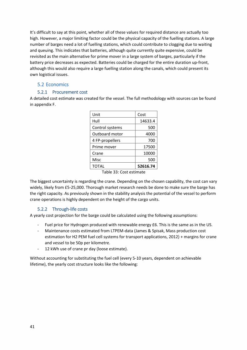
41
It’s difficult to say at this point, whether all of these values for required distance are actually too
high. However, a major limiting factor could be the physical capacity of the fuelling stations. A large
number of barges need a lot of fuelling stations, which could contribute to clogging due to waiting
and queuing. This indicates that batteries, although quite currently quite expensive, could be
revisited as the main alternative for prime mover in a large system of barges, particularly if the
battery price decreases as expected. Batteries could be charged for the entire duration up-front,
although this would also require a large fuelling station along the canals, which could present its
own logistical issues.
5.2 Economics
5.2.1 Procurement cost A detailed cost estimate was created for the vessel. The full methodology with sources can be found
in appendix F.
Unit Cost
Hull 14633.4
Control systems 500
Outboard motor 4000
4 FP-propellers 700
Prime mover 17500
Crane 10000
Misc 500
TOTAL 52616.74
Table 33: Cost estimate
The biggest uncertainty is regarding the crane. Depending on the chosen capability, the cost can vary
widely, likely from £5-25,000. Thorough market research needs be done to make sure the barge has
the right capacity. As previously shown in the stability analysis the potential of the vessel to perform
crane operations is highly dependent on the height of the cargo units.
5.2.2 Through-life costs A yearly cost projection for the barge could be calculated using the following assumptions:
- Fuel price for Hydrogen produced with renewable energy £6. This is the same as in the US.
- Maintenance costs estimated from LTPEM-data (James & Spisak, Mass production cost
estimation for H2 PEM fuel cell systems for transport applications, 2012) + margins for crane
and vessel to be 50p per kilometre.
- 12 kWh use of crane pr day (loose estimate).
Without accounting for substituting the fuel cell (every 5-10 years, dependent on achievable
lifetime), the yearly cost structure looks like the following:

42
Figure 18: Yearly cost projection per barge
The graph clearly shows that manning is the critical cost-component for yearly operations. This has
some interesting implications, which are further discussed in the next sub-chapter.
5.3 Emerging technologies As shown in the previous section, manning is the main operational cost driver. This indicates that an
unmanned fleet could significantly reduce costs in the long run. According to recent research
(Burmeister & Rødseth, 2012), (Burmeister, Bruhn, Rødseth, & Porather, 2014)most of the barriers
to implement unmanned traffic are regulatory and logistical, not technological, in nature. There are
reasons for why reduced manning could be implemented on the canals in the very near future:
A unified international ruleset is considered to be a main challenge in implementing
unmanned shipping worldwide. However, in this case the rules and legality around the
operations could be decided by the London government. Thus legal issues could be solved
easier and faster.
Another main issue is the lack of oversight over fatigue in long-traffic freight vessels without
people on board. However, for the London canals fatigue is less of an issue due to the lack
of waves, and also it should be considerably easier to perform preventative maintenance
and keep oversight of the vessels.
The predictable geographical conditions (weather, routes) on the canals should make it
relatively easy to program the vessels, and also to keep a good overview of potential pitfalls
to account for in programming.
A hypothetical system could be in the form of a number of barges running unmanned, with the main
operations viewed from a control room, with communications to each unloading point, and a
comprehensive camera view of each barge. As the reliability of the system increases, it could be
acceptable to continuously decrease the number of required operators.
An analysis of the most important implications of unmanned barging follows.
17%
6%
77%
Yearly cost projection, 1 barge
fuel maintenance manning

43
Potential gain Reasoning
Potential massive reductions in operational costs.
Manning is thought to be the main cost of running an individual barge yearly.
Increase in safety. Arguably, because the operator is taken out of the direct operation.
More efficient fleet. Without the need to maximise capacity to maximise profitability every trip, the unmanned fleet allows for varied sizes of hydrodynamically optimized vessels.
24 hr operation. Due to the small size of the control crew, and in the long run, advanced sensor technology, could provide an opportunity to operate a large fleet outside the traditional working hours. The extent would depend on the profitability, and also the safety of such operations.
Table 34: Gains from no-manning
Assessment of challenges Potential solutions
Crane operations might be difficult to program and perform safely through AI.
Crane could be controlled remotely or through an operator at each load point.
Usage of roro-racks for smaller cargo that would otherwise require detailed and challenging crane operations. Thus crane operations are only performed for larger containers.
Mooring is assumed to be difficult with an unmanned ship.
Again, mooring operators at sites
A solution with a much higher potential, would be to apply magnetic mooring along the stations. This could both negate the problem with mooring, and also help with stability during unload-operations.
Table 35: Challenges with no-manning
Assessment of risks Potential mitigations
Interaction between unmanned craft and manned recreational and other craft.
Requirement for remote-control or personal overseeing of each barge every time one passes a manned vessel.
Very slow steaming when passing another craft.
Prohibiting manned traffic on the canals.

44
A breakdown of the communications between control and vessels could have extremely damaging effects.
A fail-safe that would automatically stop the individual barges, or the entire system, dependent on how critical the breakdown is.
Table 36: Risks with no-manning
The low-manning concept needs to be verified on a small scale before it can be applied for the entire
system. Thus a barge fleet and the logistics plan should from the beginning be designed for
unmanned operations, and the relevant regulatory bodies should be involved from an early stage, so
as to be able to benefit from this as soon as possible.
5.4 Business model A tentative business model can be made using (Osterwalder, 2010). A simple overview of the key
areas of the business can be used as a tool for more in-depth discussion about strengths and
weaknesses of the venture. For this, the business model canvas can be applied.
Customer segments Our unique customer groups whose needs must be identified.
Manufacturing industry.
Catering businesses.
Domestic deliveries.
Recycling.
Food producers.
Value propositions What we are offering to our customers to make them buy our product.
Reliability: Barges can’t get stuck in traffic.
A way for people and companies to be a part of reducing air and noise pollution around the city.
Safety: Taking traffic off the road in the city.
Using the narrative of “the green barge” for own marketing purposes.
Channels How we communicate with our customers.
Setting up an internet page promoting the barges is a no-brainer (this could be a future UCL-project).
Placing leaflets in bars, grocery stores. Other word of mouth-techniques.
Social media strategies could be incorporated into the marketing plan.
When the business is up and running, the webpage should have 3 basic functions: Tracking barges (in the style of the TfL-website), placing orders, and giving feedback on service.
Customer relationships TBC.
Revenue streams How income is made.
Usage fee for cargo freight.
Potential for leasing out to companies for larger missions.
Potential for creating subscription revenues from domestic deliveries.
Potential for brokering between supplier and purchaser of cargo. Key resources The main assets needed to make the business work
The vessel(s).
Skilled operators (competencies in crane operations/cargo handling and steering the vessel itself).
Fuelling system on land.
Access to skilled maintenance personnel, either in-house or leased on-demand.
Key activities The main activities required to make the business work
Operations of vessels.
Marketing to existing and potential customers.

45
Key partnerships Fuel supplier.
If leased, vessel maintenance supplier.
Fuel transport company.
Potential strategic alliance with National Rail and/or TfL, in order to exploit economies of scale to the fullest.
Since company is acting like an intermediary for supply; need to treat customers as partners.
Cost structure Fuel costs
Manning, vessel.
Manning, onshore (marketing, administration, technical, depending on organization structure).
Maintenance.
Procurement costs for new vessels.
Table 37: Business model canvas
STRENGTHS WEAKNESSES
- CONTRIBUTES TO LOWER NOISE,
CARBON AND AIR EMISSIONS.
- CHEAPER THAN ROAD TRAFFIC AT
MEDIUM AND LOW SPEEDS.
- “LEAN” ORGANIZATION: FEW PEOPLE
CAN FREIGHT HIGH QUANTITIES.
- INFRASTRUCTURE INVESTMENTS
REQUIRED TO FULLY UTILISE POTENTIAL.
- “AUXILIARY” TRANSPORT REQUIREMENTS
FOR CUSTOMERS AWAY FROM THE
CANALS.
- EXPENSIVE EQUIPMENT, HIGH
“DOWNSIDE”.
OPPORTUNITIES THREATS
- DESCALE COSTS BY APPLYING
UNMANNED BARGES, TOGETHER WITH
MAGNETIC MOORING.
- NO INFRASTRUCTURE / WHARVES BUILT
ALONGSIDE CANAL.
Figure 19: SWOT-analysis
6 Conclusions
6.1 Summary A general cargo vessel has been designed, utilizing a HTPEM fuel cell with hydrogen to provide
London with a low-noise, zero-emissions transport alternative. The economic analysis for the vessel
indicates that a no-manning system would be extremely advantageous for the barge operation. The
paper postulates that the conditions for no-manning in the near future are favourable, and should
thus be planned for from the start.

46
6.2 Further work Several important avenues for further research has been identified, the most important of which
are:
Economics:
A comprehensive economical model detailing when it’s profitable to outmode road traffic in London
to barges. Suggested variables includes, but are not limited to:
- Profitability over various distances vs the profitability of using lorries over the equivalent
road distance: Comparisons in manning and operating costs (fuel usage, maintenance,
overhead costs).
- Speed and time comparison with lorries in various parts of the city to see where the barges
could be faster, and where they would have significant time disadvantages.
- Logistical ease of outmoding different types of cargo.
Ship types:
- A thorough customer survey to uncover the concrete market needs for a ship crane,
including an investigation into the weight limit on the types of cargo to be containerised and
unloaded by crane.
- Further investigation into a roro-craft for heavy cargo.
- An analysis on which routes each of the barge types can be used on, and their expected
profitability.
- Analysis into other specialized ship types of various sizes to serve niche markets.
Canals capacity:
- Particularly important factors are thought to be fuelling logistics and number of load/unload
points.
- Which system would be best for a large scale barge system: Centralised charging or fuelling
stations around the canals?
- Which logistical system would maximise the utilization of the barges?
- How would unmanned shipping affect the capacity of the canals?
Works Cited Burmeister, & Rødseth. (2012). Developments toward the unmanned ship.
Burmeister, Bruhn, Rødseth, & Porather. (2014). Can unmanned ships improve navigational safety?
Transport Research Arena. Paris.
Carlton, J. (2007). Marine Propellers and Propulsion, 2nd edition. Elsevier Ltd.
Chalmers. (2007). Surface ship structural design.
Chandra, & Prakash. (2013). Numerical estimation of shallow water resistance of a river sea ship
using CFD.
Commons, C. (n.d.).
DNV. (2011). Fuel Cells for Ships.

47
Haimov, H. (2014). SILENV - Main results and CEHIPAR contribution.
Han, Charpentier, & Tang. (2012). State of the art of fuel cells for ship applications.
Hekkenberg. (2014). A building cost estimation for inland ships.
Hekkenberg, Rotteveel, & Liu. (2014). Design Guidelines and Empirical Evaluation Tools for Inland
Ships. European Inland Waterways Navigation Conference.
Hekkenberg, Tugt, v., Till, & Zanden, V. d. (2007). Strategy to increase innovation in inland
waterways.
James, & Spisak. (2012). Mass production cost estimation for H2 PEM fuel cell systems for transport
applications.
James, Spisak, & Colella. (2012). Manufacturing cost analysis of stationary fuel cell systems.
Kordesch, & Cifrain. (2003). A comparison between the alkaline fuel cell and the polymer exchange
membrane fuel cell.
Molland, Turner, & Hudson. (2011). Ship Resistance and Propulsion. Cambridge Press.
Mosaad, Mosleh, El-Kilani, & Yedhia. (2010). Propeller design for minimum induced vibrations.
Osterwalder, A. (2010). Business model generation.
Panasonic. (2011). Lithium-ion battery.
Papanikoulao, A. (2014). Ship design.
Partnership, Park Royal. (2007). Grand Union Canal waste and recyclate freight study.
PBA. (2007). Assessing Barriers to Freight.
PM Cranes Website. (n.d.). Knuckle boom cranes.
Powersonic. (2014). General purpose battery specifications.
Rawson, & Tupper. (1994). Basic Ship Theory. Butterworth-Heinemann.
Selfridge, M. (2014). Grillage data sheets.
Sharaf, & Orhan. (2014). An overview of fuel cell technology: Fundamentals and applications.
Sperling, Overschie, Hekkenberg, & Mulder. (2007). Sustainable Technologies in Inland Navigation .
The Daily Telegraph. (2012). London's food basket struggles to keep costs down as even foodies cut
back.
Troncoso, M. (2013). Batteries for Marine applications. Trondheim: NTNU.
UN. (2011). White Paper on European Inland Waterways.
APPENDIX A: FUEL USAGE, MASS AND VOLUME CALCULATIONS The size of the fuel tanks were calculated using the following method:
Fuel calorific value – C [kJ/kg]

48
Mass flow rate – m [kg/s]
Power – P [kW]
Fuel cell efficiency – eta [nondimensional]
𝐶 ∗ 𝑚 =𝑃
𝑒𝑡𝑎 (3)
𝑚 =𝑃
𝑒𝑡𝑎∗𝐶 (4)
Mass/kWh:
=𝑚∗1ℎ𝑟
𝑃∗1ℎ𝑟 (5)
=𝑚∗3600𝑠
𝑃(𝑘𝑊ℎ) (6)
Applying (3) to (6)
=𝑃∗3600
𝑃∗𝐶∗𝑒𝑡𝑎 (7)
=3600
𝑒𝑡𝑎∗𝐶 [
𝑘𝑔
𝑘𝑊ℎ] (8)
This can be used to calculate kg fuel:
𝑡𝑖𝑚𝑒 =𝑙𝑒𝑛𝑔𝑡ℎ
𝑣𝑒𝑙𝑜𝑐𝑖𝑡𝑦 (9)
[kWh] = P*time(hr) (10)
𝑘𝑔 = [𝑘𝑔
𝑘𝑊ℎ] ∗ [𝑘𝑊ℎ] (11)
i.e. (11) = (8)*(10)
APPENDIX B: COST Hull
The hull-cost was calculated using the data of (Hekkenberg, A building cost estimation for inland
ships, 2014). This divides the calculation into labour costs (dependent on L, B, D), and steel weight.
Steel weight is assumed to be €950/tonne, 2014 prices (as a comparison it can be said that steel
prices are quoted as of August 2015 to be around $5-600/tonne, so possibly conservative). The
method is based on ships from 30-130 meters, thus somewhat outside the range of the current one.
It does not take into account the block coefficient of the vessel.
Fuel cell
A number of cost estimates for fuel cell exists, and they’re usually based on a higher production rate
than the current. (James & Spisak, Mass production cost estimation for H2 PEM fuel cell systems for
transport applications, 2012) estimated that the cost per unit of an 80kW PEMFC was around $190
at production levels of 1,000 units (for bus/vehicle-purposes). (James, Spisak, & Colella,

49
Manufacturing cost analysis of stationary fuel cell systems, 2012) estimated that for stationary HT
fuel cells at around 25 kw capacity, could be between $700-1,100, depending on production rate.
Data pointed to fuel cells for automotive/prime mover purposes being considerably cheaper than for
stationary purposes. However, due to lack of specific data for automotive HTPEMFC, the cost was
assumed to be $900 (£600) per kW.
Batteries
The price for li-ion batteries were taken to be in the range of $350/kWh (values inferred from online
sources predicting how the price may change, as there were no unified estimates).
Crane
Because of the inability to get any good industry data, it was resorted to estimate prices through E-
bay (the online auction service). The price range for new articulating cranes were enormous, and in
most cases they were mounted to large trucks, probably inflating the price.
Without the vehicles, it was estimated the price for 5-to-10-ton cranes could be down to £5-10,000,
and a 25-ton-crane could be from £15-20,000 and even more. However, an estimate from a crane
producer for a tailored crane should be procured when the required capacity is decided.
Outboard motor
Estimated from similar motors (25-35 HP) at E-bay and company websites ($3-5000 for new ones),
and added margins to account for the tailoring of a duct.
Propeller
Estimated from similar propellers on company websites.
Misc and control system
Simple assumptions made to account for safety equipment etc, and wheel/electronic control
systems.
APPENDIX C: STRUCTURES Bending moment, sample:
Section 0 2 4 6 8 10 12 14 16 18 20
Point weight
LS weight/m 0.80 0.70 0.70 0.70 2.70 0.70 0.70 0.70 0.70 0.70
Payload weight/m 0.00 0.00 0.00 0.00 0.00 0.00 0.00 0.00 0.00 0.00
Section area 4.45 4.45 4.45 4.45 4.45 4.45 4.45 4.45 4.45 4.45 4.20
Buoyancy/m 0.82 0.82 0.82 0.82 0.82 0.82 0.82 0.82 0.82 0.82
Tonnes -0.02 -0.12 -0.12 -0.12 1.88 -0.12 -0.12 -0.12 -0.12 -0.12
Force N -214 -1195 -1195 -1195 18425 -1195 -1195 -1195 -1195 -1195
deltaSF -428 -2390 -2390 -2390 36850 -2390 -2390 -2390 -2390 -2390
SF 0 -428 -2818 -5208 -7598 29252 26862 24471 22081 19691 17301
Mid shear -214 -1623 -4013 -6403 10827 28057 25667 23276 20886 18496
deltaBM -428 -3246 -8026 -12807 21653 56113 51333 46553 41773 36993

50
BM 0 -428 -3674 -
11701 -24507 -2854 53259 104592 151145 192918 229911
corr factor 13557 27115 54230 81345 108459 135574 162689 189804 216919 244034
BM corr 0 -
13985 -
30789 -
65930 -
105852 -
111313 -82315 -58097 -38659 -24001 -14123
Safety factor 0
-19580
-43105
-92302
-148192
-155838
-115241
-81335.2
-54121.9
-33600.9 -19772
Comment: Weight to buoyancy balance integrated twice using trapezoidal method, and corrected so
that the moment is 0 at the end of the hull girder.
Cross-sections were modelled as simple rectangles, except for
Basic equations for required section modulus:
𝑍 =𝑀𝑏
𝜎𝑠𝑎𝑓𝑒𝑡𝑦 (12)
𝑍 =𝐼
𝑦 (13)
Where Mb is the design bending moment as found from weight integration. I, Z and y are section
second moment of inertia, section modulus and distance from NA to strength and keel deck for the
respective criteria.
Compressive buckling:
Design shear stress:
𝜏𝑚𝑎𝑥 =𝐴𝑠𝑒𝑐𝑡𝑖𝑜𝑛∗𝑧∗𝐹
𝐼∗𝑡𝑡 (14)
Where 𝐴𝑠𝑒𝑐𝑡𝑖𝑜𝑛 is the area of the section above the neutral axis, z is the distance from the shear
centre (NA) to the strength deck,F is the design shear force (found as the max force during the
integration), I is the second moment of inertia of the cross section, tt is the total thickness of the 2
plates at the neutral axis.
Buckling of plates in shear:
𝜏𝑠𝑐 = 𝜒 ∗ 𝐸 ∗ (𝑡
𝑏)
2 (15)
Buckling of panels in shear:
𝜏𝑠𝑐 = 𝐾 ∗ 𝐸 ∗ (𝑡
𝑏)
2 (16)
E, t and b are Youngs modulus, plate thickness and stiffener spacing respectively. CHI and K are read
off from (Selfridge, 2014) data sheets G11 and G23 respectively.
Local strength checked with SBT, standard maximum bending moments:
𝑀𝑏 =𝑃∗𝑙2
4 (17)
Where P is load in N/m.
Equation for weight estimation:

51
((∑ 𝐿 ∗ 𝑡 + ∑ 𝑛 ∗ 𝐴𝑠𝑡𝑖𝑓𝑓𝑒𝑛𝑒𝑟)) ∗ 𝜌𝑠𝑡𝑒𝑒𝑙 (18)
Where L and t are plate length and thickness respectively.
A presentation of plate thicknesses and stiffener sizes follows.
FORE:
Area no t [m] Stiffener area
Top deck 0.0038 0.0001
Side shell 1 0.0038 0.0001
Side shell 2 0.0038 0.0001
Side shell 3 0.0038 0.0001
Bottom plate 0.0038 0.0001
Double plate 0.0038 0.0001
Table X1: Wheelhouse
MID:
Area no t [m] Stiffener area
Top side 0.0045 0.00023
Upper side below waterline 0.0045 0.00023
Lower side beow waterline 0.0045 0.00023
Cargo deck 0.0045 0.00023
Bottom plate 0.0044 0.0006
Table X2: Fore cargo hold
Area no t [m] Stiffener area
Top side 0.0045 0.0002
Upper side below waterline 0.0045 0.0002
Lower side beow waterline 0.0045 0.0002
Cargo deck 0.0045 0.0002
Bottom plate 0.0044 0.00026
Table X3: Aft cargo hold
APPENDIX D: STABILITY THEORY The GZ-curve was estimated by Attwoods formua for wall-sided hulls:
𝐺𝑍 = (𝐺𝑀 + 0.5 ∗ 𝐵𝑀 ∗ tan2 𝑡ℎ𝑒𝑡𝑎) ∗ sin(𝑡ℎ𝑒𝑡𝑎) (19)
Area under curve found by integrating numerically using trapezoidal rule.

52
Static stability data such as KB, BM, GM, LCF, LCB found through hydrostatic program.
Trim:
𝑀𝑡
𝑀𝑇𝐶= 𝑡𝑟𝑖𝑚[𝑚] (19)
Where MTC
𝑀𝑇𝐶 = 𝑟ℎ𝑜 ∗ 𝑔 ∗ 𝐼𝑦𝑦 (20)
Where rho is water density, g is gravity and Iyy is the second moment of inertia over the y-axis of the
ship.
Parallell sinkage:
𝛿𝑎𝑓𝑡 =𝐿𝐶𝐹−𝐴𝑃
𝐿 (21)
𝛿𝑓𝑜𝑟𝑒 =𝐿𝐶𝐹−𝐹𝑃
𝐿 (22)