barrel ponics
DESCRIPTION
aquaponicsTRANSCRIPT
1
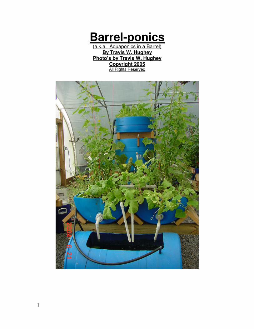
Barrel-ponics
(a.k.a. Aquaponics in a Barrel) By Travis W. Hughey
Photo’s by Travis W. Hughey Copyright 2005 All Rights Reserved

2
Conditions of Use Statement This document, in part or in its entirety, may be copied, reproduced or adapted to meet local needs without permission from the author or publishers, provided credit is given to Travis W. Hughey. These provisions apply only provided the parts reproduced are distributed free or at cost – not for profit. Travis W. Hughey would appreciate being sent a copy of any materials in which text or illustrations have been adapted. For reproduction on commercial basis, permission must be first obtained from Travis W. Hughey. Any commercial or for sale application of the Flood Valve technology is strictly forbidden without prior approval in writing from Travis W. Hughey. Travis W. Hughey can be reached at [email protected] .

3
Table of Contents
Cover Page………………………………..................................................... 1.
Conditions of Use Statement………………………………........................ 2.
Table of Contents………………………………........................................... 3.
Introduction………………………………..................................................... 4. How It All Began………………………………............................................. 5. Let the Danger Begin!……………………………......................................... 6.
Jumpin’ In………………………………........................................................ 7. “I Don’t Have the Education!”………………………….................................. 7. The Nitrogen Cycle……………………………….......................................... 7. What the Plants Need………………………………....................................... 8. What the Fish Need……………………………….......................................... 9.
Parts List for Aquaponics System………………………………..................10.
Swimin’ with the Fishes……………………………….................................. 13.
Barrel Growbed Construction………………………………........................ 22.
Building the Stand……………………………….......................................... 28.
Building the Floodvalve………………………………................................. 43. Assemble the Sub-assemblies………………………………......................... 49. Let’s Put This Thing Together……………………………….......................... 61.
The Floating Raft Tank………………………………................................... 69.
Movin’ the Water………………………………............................................. 75. Plumbing It All Together………………………………................................ . 76.
Options………………………………............................................................ 80.
Maintenance……………………………….................................................... 87.
Starting the System………………………………........................................ 89.
Why I do What I Do………………………………......................................... 91. A Little Bit Of What To Look Forward To………………………….............. 92.

4
Introduction If you are looking for an introduction to aquaponics that is simple to build, fun to watch and demonstrate to friends and family the joy of soil less gardening. This small unit may be for you. It is capable of growing various vegetables and herbs and would be a wonderful addition to the home kitchen as a source of fresh herbs and occasionally (depending on the species used) a fish or two. What it most likely won't do is provide the vegetables to sustain someone on it's own. That is for a much larger system. Fish production is also limited because of the small size of the unit. The actual production possible is mainly dependant on the operators ability to manage it. I have personally grown tilapia in this system to about 1/2 Lb. Not a lot of them, just a few. I have grown tomato plants and papaya trees in this system with nothing more than 4 each of 1/2Lb. tilapia as the nutrient source. Remember this is not magic. This systems fish tank at the lowest point in the cycle will only have a little over 20gal. of water in it. In my opinion it's simply not practical in the real world to grow high densities of fish and have a system that is forgiving at the same time. This unit is specifically designed as an introduction to aquaponics and to make one familiar with the principals involved with minimal expense. It is very adaptable to situations where conventional electric pumps may not be practical. This is all about learning fun and not intended to be a commercial unit in itself although I believe the principles can be enlarged to do so. Please read this material in it's completion before attempting to build this unit. If you are unfamiliar with something don't worry about it too much. It will come clear as the project progresses. Before we get into the system please allow me to give a little information about myself.
5
How it all Began
I first became interested in aquaponics after acquiring a greenhouse in the spring of 2002 from a local middle school here in coastal South Carolina. The school system here was converting to a "Technical curriculum" and no longer needed the mainstay piece of equipment of their horticulture class. A donation to the PTA and a few weekends of hard work by my family and the green house was on our property. Now what to do with it? It was a 28 x 45 hoop style greenhouse with cooler, fans, and all the standard equipment. I then started researching what to do. The first thing I considered was hydroponics but decided it wasn't for me after visiting a hydroponic tomato operation and found out there was a hazardous waste byproduct that had to be hauled off periodically. I'm not saying hydroponics is a bad thing at all. I'm just saying it wasn't for me at the time. I wanted to do something unique and during a web search ran across the term "aquaponics". This intrigued me as I was a biology major at Oral Roberts University but never got to finish my education there. This was a natural fit, aquaculture and horticulture in a soiless medium. The search led me to Tom and Paula Spraneo. They were selling a manual on aquaponics so I ordered it. To say it opened my eyes was an understatement to say the least. Their manual is very informative and I highly recommend it if it is still available. Tom and Paula have done a great service to have helped in the pioneering of this great technology. I must say I was a little intimidated at first but became more and more comfortable with the information the more I studied it. Our quest then led us to an opportunity to attend an aquaculture workshop in 2003 that included aquaponics as one of the topics. The workshop was hosted by Charlie Johnson of Aquaculture International in Bryson City, NC. It was a very informative time with a lot of contacts I still have today. There were a lot of mission minded types there and they as well as I saw the importance of this technology in feeding the poor. There was one person there that really grabbed my attention. His name is Frank NcNeely and he is the owner of Aqua-Terra Gardens in Springfield, MO. He was doing aquaponics in old recycled fiberglass bathtubs salvaged from a hotel renovation. That inspired me and got me to thinking. I had been putting together a mold to make my growbeds out of fiberglass. Why not use an abundance of plastic barrels I had laying around. By the time my wife (Lori) and I returned home I had the basic idea on how to use these barrels as growbeds. I couldn't wait, but had to, as my job did not afford much time to pursue my newfound passion. I definitely had enough information to be dangerous now.

6
Let the Danger Begin!!
Beginning in September of 2003 I started putting together a S&S based system in concept but using low cost materials. That's the beauty of aquaponics, you are only limited by your imagination. The system was started in early October of 2003 and I made all the mistakes everyone talks about. Most mistakes are made early on from mere impatience. Trying to push the system too hard in the beginning is a sure formula for disaster. It is no fun carrying out buckets full of dead fish and frantically trying to find out why they are dying. Every person new to aquaculture has the potential to be a serial fish killer. I was no exception. Once the system stabilizes though it is amazingly resilient. My experience with this system has taught me many things and I look forward learning much more in the future. After working with this system it became apparent to me that this technology would be a Godsend to areas of the world where there is no soil or it is very poor. Many cultures in the world suffer from malnutrition and I believe aquaponics may be one of the solutions to the problem. One of the problems is that aquaponics is somewhat technical and may not be appropriate in it's current form. This is what got me to thinking about a small system that could be built in orphanages and teach the principals of aquaponics in such a way it could be easily understood and become commonplace. For this to happen the technology has to be reliable and in-expensive. I started working on the idea for a small barrel based system. This system had to be simple, visual and reliable. I started working on a variation of a system that Frank NcNeely used as a training tool. It involved using a toilet float attached directly to the flapper of a standard flush valve. The problem I found was under very low flow situations the flapper would lift just enough to allow the water to flow but wouldn't dump the tank as needed. It was about 9:00 in the evening in March of 2004 and I was coming up against a wall. Frustrated and feet soaking wet from playing with water for hours I just stopped and prayed. I knew the Creator of the universe had the answer to the problem as simple as this, I just needed to clear my frustration and listen to Him. By 11:00 that night I had the initial prototype working on even the slightest trickle. A few refinements to the initial concept and the first system was put together using the barrel half growbeds. That system is still in operation today. Working day and night with the slightest maintenance required. The flood valve is fully adjustable as to flood volume and cycle time parameters and uses no timers or float switches for it to operate. It is very inexpensive to build and is just plain fun to watch operate. It is very visual and definitely captures the attention of passers by. Well, let's get started with the system.
7
Jumpin' In
"I Don't Have the Education !"
First let me explain that you do not have to have a college degree to be successful with aquaponics on the home level. Just like you do not have to understand the chemical process that goes on during combustion in the engine of your car to successfully operate it you do not need to fully understand the complexities of the biochemistry involved in aquaponics. You do need to know a few things though just as you do to operate your car. If you get the chance to attend an aquaponics course or seminar I highly recommend it. If not there is always the school of hard knocks. Just be sure you start small. That's what this manual is all about. The first basic of aquaponic is the nitrogen cycle. It is how toxic ammonia fish waste is ultimately converted to not as toxic nitrates. The following is information provided from Nelson/Pade Multimedia. Thanks Rebecca!!
The Nitrogen Cycle Reprinted with permission from Nelson/Pade Multimedia, publishers of the
Aquaponics Journal, www.aquaponics.com
More than 50% of the waste produced by fish is in the form of ammonia, secreted through the gills and in the urine. The remainder of the waste is excreted as fecal matter, undergoes a process called mineralization which occurs when Heterotrophic bacteria consumes fish waste, decaying plant matter and uneaten food, converting all three to ammonia and other compounds. In sufficient quantities ammonia is toxic to plant and fish. Nitrifying bacteria, which naturally live in the soil, water and air convert ammonia first to nitrite (Nitrosomonas bacteria) and then to nitrate (Nitrobacter) which the plants consume. Nitrifying bacteria will thrive in the gravel beds and in the water in the system. The plants readily take up the nitrites and nitrates in the water and, in consuming it, help to keep the water clean and safe for the fish.

8
What the Plants Need
Plants need nutrients in the proper amounts, oxygen, CO2, water and light. They can come from natural or artificial means. Aquaponics takes advantage of a natural process in a controlled environment and fulfills these requirements. Plant roots need oxygen which brings us to the need for a flood and drain requirement for the growbeds. If plant roots would tolerate continual emersion in water we would not need to drain the grow beds and could simply flow water through continuously. There are several different schemes to accomplish this using timers, float switches or even computer control. The flood valve eliminates the need for such technology. I'm not saying technology is bad. I use it when available. It is a good thing. It's just not available everywhere. I have grown a large variety of vegetables in my system and the only one's I have had trouble with are squash. They seem to be very sensitive to the moisture level of the system and almost always have powdery mildew problems. A partial list of successfully grown vegetables, fruits and herbs in my system include tomatoes, onions, peppers (sweet and hot from bell to habanero), beans, beets, brocolli, basil, cilantro, papaya, collards, cucumbers, carrots, lettuce, stevia, moringa, dill, chard, okra, peas and parsley to name a few. The plants thrive in this environment and the planting densities are much higher than in a conventional garden.
9
What the Fish Need
Fish need clean oxygen rich water and reliable feed to thrive. The water also needs to be at the right temperature. Conditions that are tolerable vary from species to species. One would have to get information elsewhere concerning the specific species desired. All you need is an aquatic animal with gills to provide the basic nutrients for the nitrogen cycle to operate and the bacteria to make the conversion for the plants to take up the nutrients. It is a natural process that simply has to have the right conditions to occur. The bacteria and plants in my system keep the water crystal clear and the water has the sweet smell of healthy creek water. This is one of the basic indicators I use to check the overall health of the system. If it get's out of balance you will know it. When things die they smell bad. Whether it's fish or microbes. The most common cause of problems in a stabilized system is over feeding. The water gets cloudy and the first reaction is to get nervous about the change. I just back off the feed for a day or two. The fish will be fine unless there is a toxin causing the problem. At which point they will probably be lost anyway. The key to all this is to familiarize oneself with the day to day operation and nuances. It will become intuitive after a while. Have fun with this and don't worry too much. As far as feed goes it all depends on the fish you are using. I have tilapia in my system. Tilapia are a wonderful choice in tropical climates as they are extremely forgiving as far as water quality is concerned and they are not picky eaters. They are vegetarians and will consume leafy scraps from the garden as well as water hyacinth, water lettuce and duckweed. I have even had them gobble up dried rabbit pellets just as if it were fish feed. They do very well on standard floating fish feed and I have even heard of people feeding them dog food when the fish pellets are not available. Don't forget about the natural feeds available in your area. There are large amounts of protein flying about in the form of insects and would be attracted by a light suspended over the fish tank at night. Not to mention worms, grubs, maggots, etc...
10
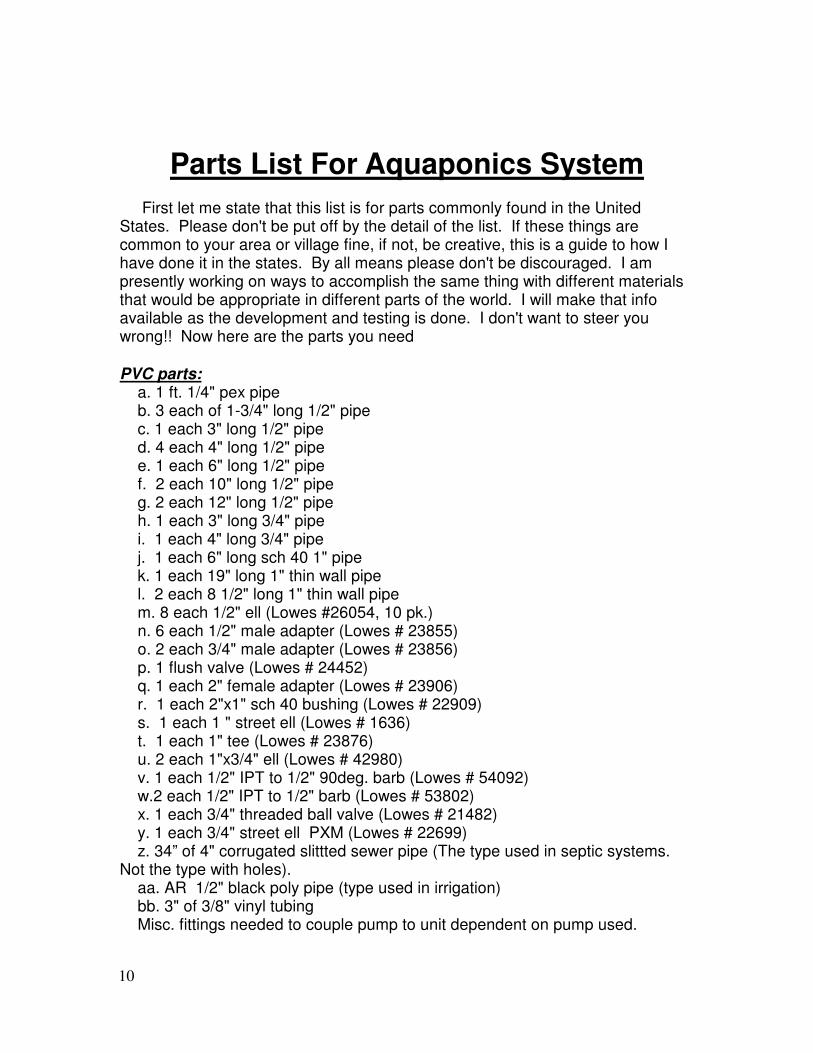
Parts List For Aquaponics System
First let me state that this list is for parts commonly found in the United States. Please don't be put off by the detail of the list. If these things are common to your area or village fine, if not, be creative, this is a guide to how I have done it in the states. By all means please don't be discouraged. I am presently working on ways to accomplish the same thing with different materials that would be appropriate in different parts of the world. I will make that info available as the development and testing is done. I don't want to steer you wrong!! Now here are the parts you need
PVC parts: a. 1 ft. 1/4" pex pipe b. 3 each of 1-3/4" long 1/2" pipe c. 1 each 3" long 1/2" pipe d. 4 each 4" long 1/2" pipe e. 1 each 6" long 1/2" pipe f. 2 each 10" long 1/2" pipe g. 2 each 12" long 1/2" pipe h. 1 each 3" long 3/4" pipe i. 1 each 4" long 3/4" pipe j. 1 each 6" long sch 40 1" pipe k. 1 each 19" long 1" thin wall pipe l. 2 each 8 1/2" long 1" thin wall pipe m. 8 each 1/2" ell (Lowes #26054, 10 pk.) n. 6 each 1/2" male adapter (Lowes # 23855) o. 2 each 3/4" male adapter (Lowes # 23856) p. 1 flush valve (Lowes # 24452) q. 1 each 2" female adapter (Lowes # 23906) r. 1 each 2"x1" sch 40 bushing (Lowes # 22909) s. 1 each 1 " street ell (Lowes # 1636) t. 1 each 1" tee (Lowes # 23876) u. 2 each 1"x3/4" ell (Lowes # 42980) v. 1 each 1/2" IPT to 1/2" 90deg. barb (Lowes # 54092) w.2 each 1/2" IPT to 1/2" barb (Lowes # 53802) x. 1 each 3/4" threaded ball valve (Lowes # 21482) y. 1 each 3/4" street ell PXM (Lowes # 22699) z. 34” of 4" corrugated slittted sewer pipe (The type used in septic systems. Not the type with holes). aa. AR 1/2" black poly pipe (type used in irrigation) bb. 3" of 3/8" vinyl tubing Misc. fittings needed to couple pump to unit dependent on pump used.
11
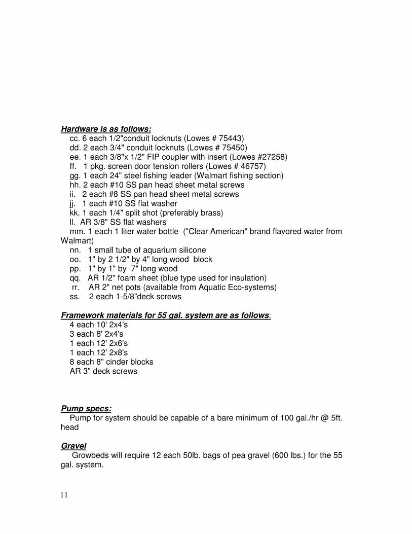
Hardware is as follows: cc. 6 each 1/2"conduit locknuts (Lowes # 75443) dd. 2 each 3/4" conduit locknuts (Lowes # 75450) ee. 1 each 3/8"x 1/2" FIP coupler with insert (Lowes #27258) ff. 1 pkg. screen door tension rollers (Lowes # 46757) gg. 1 each 24" steel fishing leader (Walmart fishing section) hh. 2 each #10 SS pan head sheet metal screws ii. 2 each #8 SS pan head sheet metal screws jj. 1 each #10 SS flat washer kk. 1 each 1/4" split shot (preferably brass) ll. AR 3/8" SS flat washers mm. 1 each 1 liter water bottle ("Clear American" brand flavored water from Walmart) nn. 1 small tube of aquarium silicone oo. 1" by 2 1/2" by 4" long wood block pp. 1" by 1" by 7" long wood qq. AR 1/2" foam sheet (blue type used for insulation) rr. AR 2" net pots (available from Aquatic Eco-systems) ss. 2 each 1-5/8”deck screws Framework materials for 55 gal. system are as follows: 4 each 10' 2x4's 3 each 8' 2x4's 1 each 12' 2x6's 1 each 12' 2x8's 8 each 8" cinder blocks AR 3" deck screws Pump specs: Pump for system should be capable of a bare minimum of 100 gal./hr @ 5ft. head Gravel Growbeds will require 12 each 50lb. bags of pea gravel (600 lbs.) for the 55 gal. system.
12
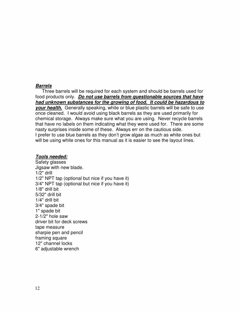
Barrels Three barrels will be required for each system and should be barrels used for food products only. Do not use barrels from questionable sources that have had unknown substances for the growing of food. It could be hazardous to your health. Generally speaking, white or blue plastic barrels will be safe to use once cleaned. I would avoid using black barrels as they are used primarily for chemical storage. Always make sure what you are using. Never recycle barrels that have no labels on them indicating what they were used for. There are some nasty surprises inside some of these. Always err on the cautious side. I prefer to use blue barrels as they don’t grow algae as much as white ones but will be using white ones for this manual as it is easier to see the layout lines. Tools needed: Safety glasses Jigsaw with new blade. 1/2" drill 1/2" NPT tap (optional but nice if you have it) 3/4" NPT tap (optional but nice if you have it) 1/8" drill bit 5/32" drill bit 1/4" drill bit 3/4" spade bit 1" spade bit 2-1/2" hole saw driver bit for deck screws tape measure sharpie pen and pencil framing square 12" channel locks 6" adjustable wrench
13
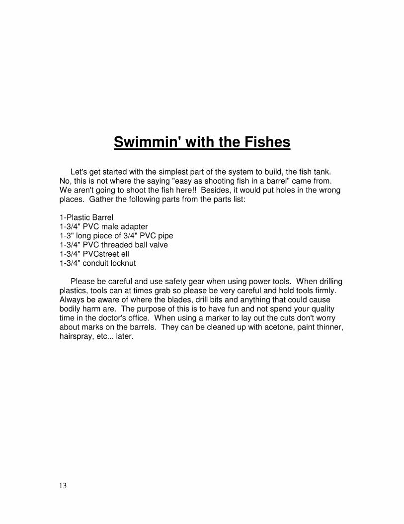
Swimmin' with the Fishes
Let's get started with the simplest part of the system to build, the fish tank. No, this is not where the saying "easy as shooting fish in a barrel" came from. We aren't going to shoot the fish here!! Besides, it would put holes in the wrong places. Gather the following parts from the parts list: 1-Plastic Barrel 1-3/4" PVC male adapter 1-3" long piece of 3/4" PVC pipe 1-3/4" PVC threaded ball valve 1-3/4" PVCstreet ell 1-3/4" conduit locknut Please be careful and use safety gear when using power tools. When drilling plastics, tools can at times grab so please be very careful and hold tools firmly. Always be aware of where the blades, drill bits and anything that could cause bodily harm are. The purpose of this is to have fun and not spend your quality time in the doctor's office. When using a marker to lay out the cuts don't worry about marks on the barrels. They can be cleaned up with acetone, paint thinner, hairspray, etc... later.
14
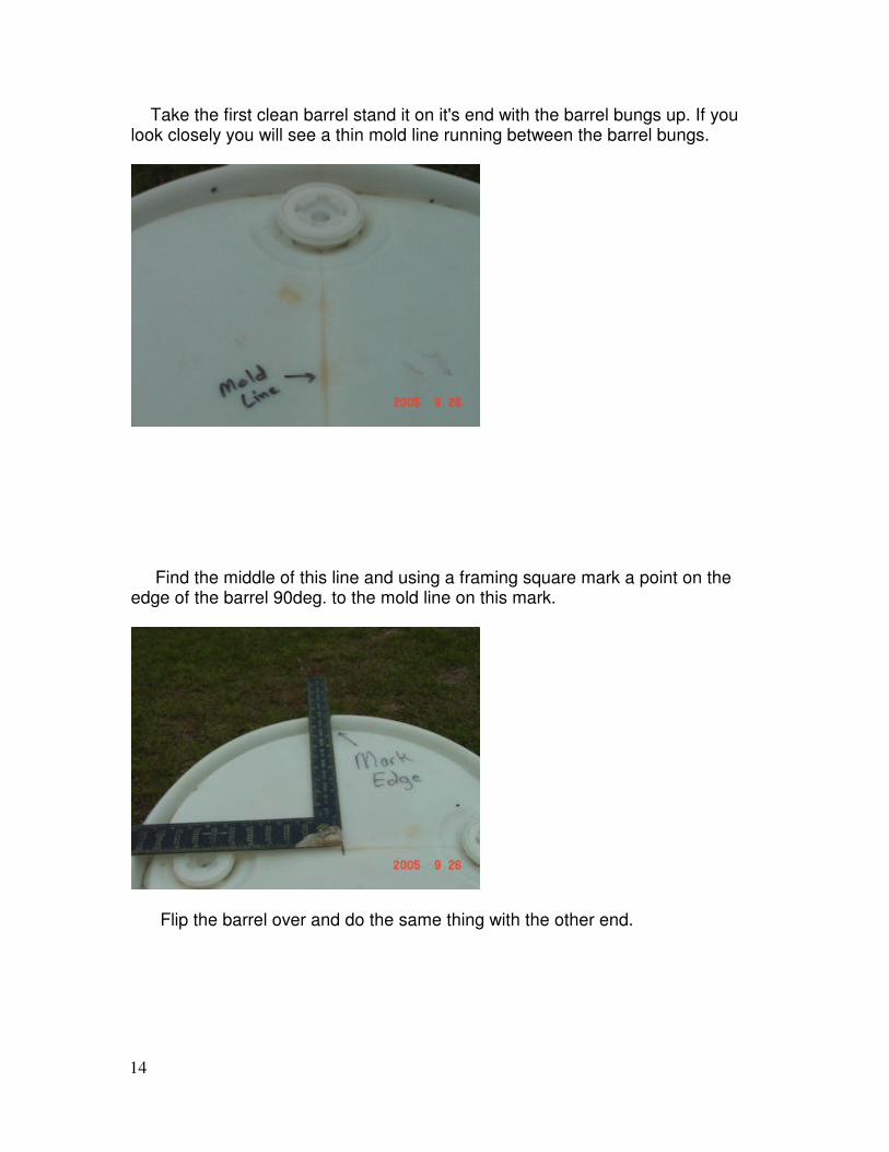
Take the first clean barrel stand it on it's end with the barrel bungs up. If you look closely you will see a thin mold line running between the barrel bungs.
Find the middle of this line and using a framing square mark a point on the edge of the barrel 90deg. to the mold line on this mark.
Flip the barrel over and do the same thing with the other end.
15
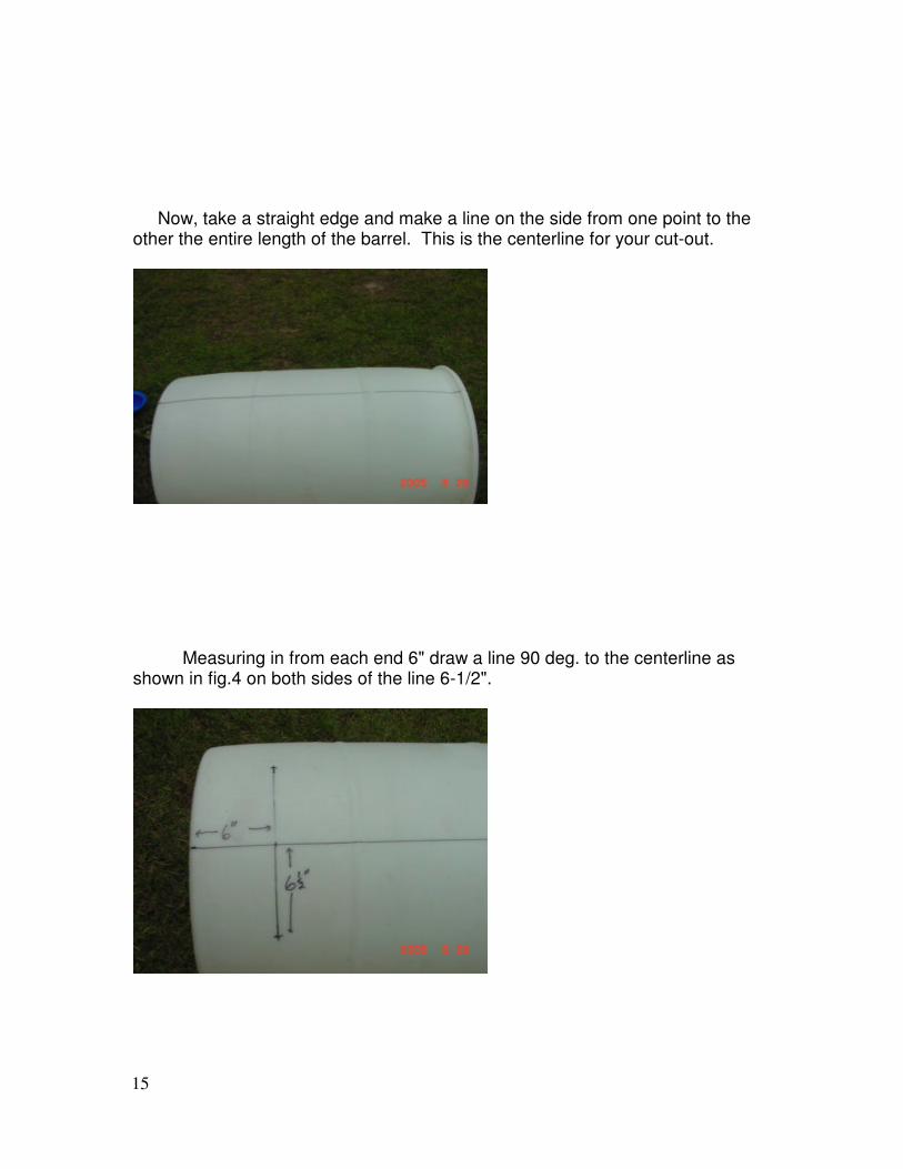
Now, take a straight edge and make a line on the side from one point to the other the entire length of the barrel. This is the centerline for your cut-out.
Measuring in from each end 6" draw a line 90 deg. to the centerline as shown in fig.4 on both sides of the line 6-1/2".
16
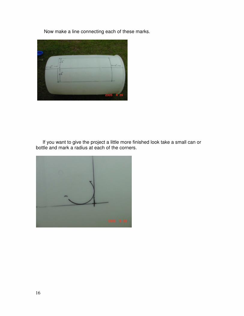
Now make a line connecting each of these marks.
If you want to give the project a little more finished look take a small can or bottle and mark a radius at each of the corners.

17
Cut out the center section being careful to secure the barrel while cutting. Clean up the edges of the cut with sandpaper or I use a knife blade and scrape the edges clean.
This is what it looks like with the center section cut out.
18
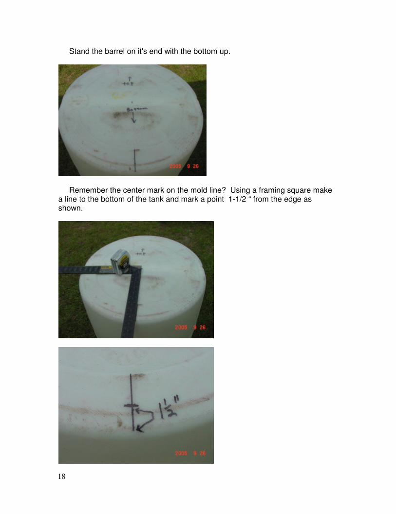
Stand the barrel on it's end with the bottom up.
Remember the center mark on the mold line? Using a framing square make a line to the bottom of the tank and mark a point 1-1/2 “ from the edge as shown.
19
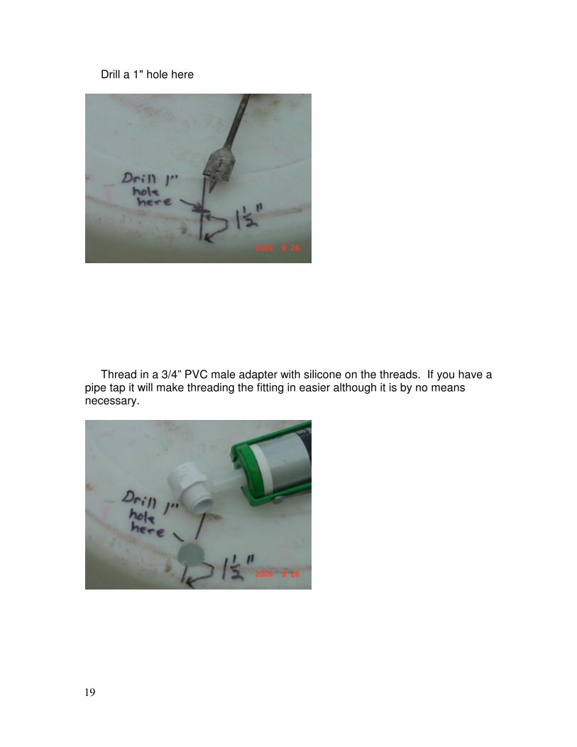
Drill a 1" hole here
Thread in a 3/4” PVC male adapter with silicone on the threads. If you have a pipe tap it will make threading the fitting in easier although it is by no means necessary.
20
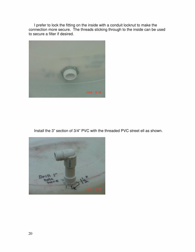
I prefer to lock the fitting on the inside with a conduit locknut to make the connection more secure. The threads sticking through to the inside can be used to secure a filter if desired.
Install the 3” section of 3/4” PVC with the threaded PVC street ell as shown.
21
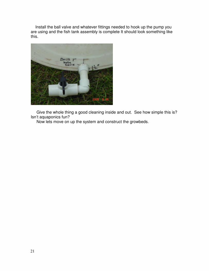
Install the ball valve and whatever fittings needed to hook up the pump you are using and the fish tank assembly is complete It should look something like this.
Give the whole thing a good cleaning inside and out. See how simple this is? Isn’t aquaponics fun? Now lets move on up the system and construct the growbeds.
22
Barrel Growbed Construction
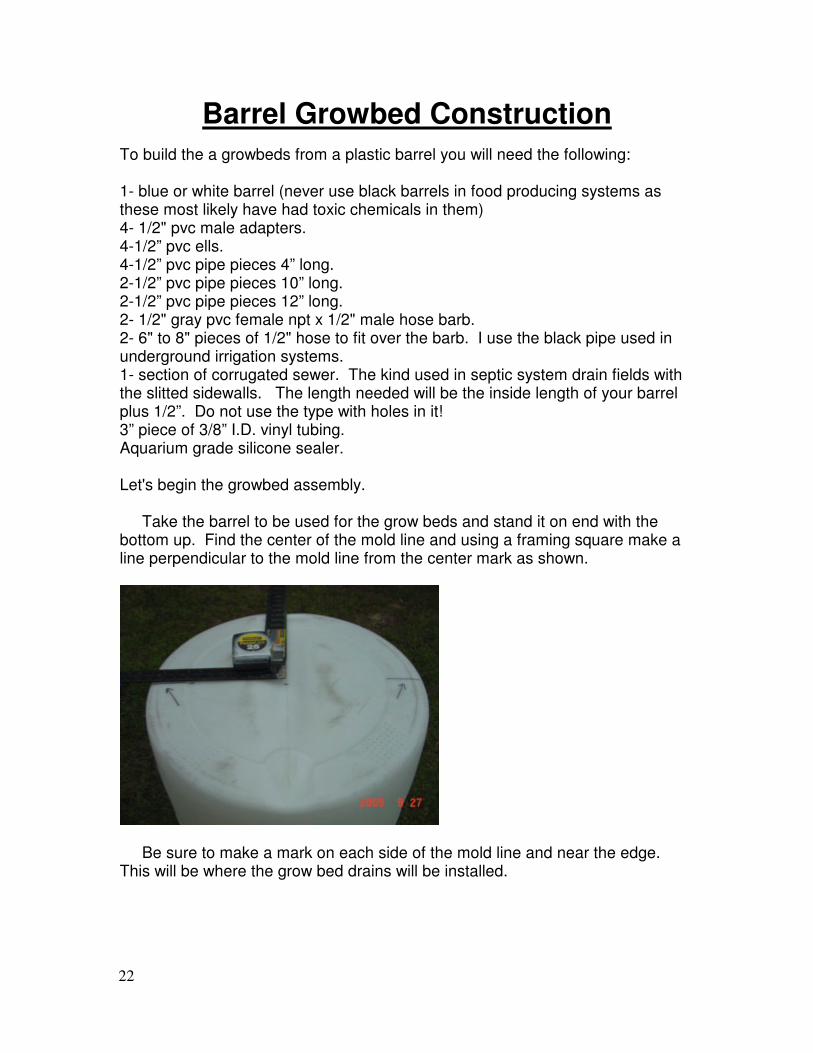
To build the a growbeds from a plastic barrel you will need the following: 1- blue or white barrel (never use black barrels in food producing systems as these most likely have had toxic chemicals in them) 4- 1/2" pvc male adapters. 4-1/2” pvc ells. 4-1/2” pvc pipe pieces 4” long. 2-1/2” pvc pipe pieces 10” long. 2-1/2” pvc pipe pieces 12” long. 2- 1/2" gray pvc female npt x 1/2" male hose barb. 2- 6" to 8" pieces of 1/2" hose to fit over the barb. I use the black pipe used in underground irrigation systems. 1- section of corrugated sewer. The kind used in septic system drain fields with the slitted sidewalls. The length needed will be the inside length of your barrel plus 1/2”. Do not use the type with holes in it! 3” piece of 3/8” I.D. vinyl tubing. Aquarium grade silicone sealer. Let's begin the growbed assembly. Take the barrel to be used for the grow beds and stand it on end with the bottom up. Find the center of the mold line and using a framing square make a line perpendicular to the mold line from the center mark as shown.
Be sure to make a mark on each side of the mold line and near the edge. This will be where the grow bed drains will be installed.
23
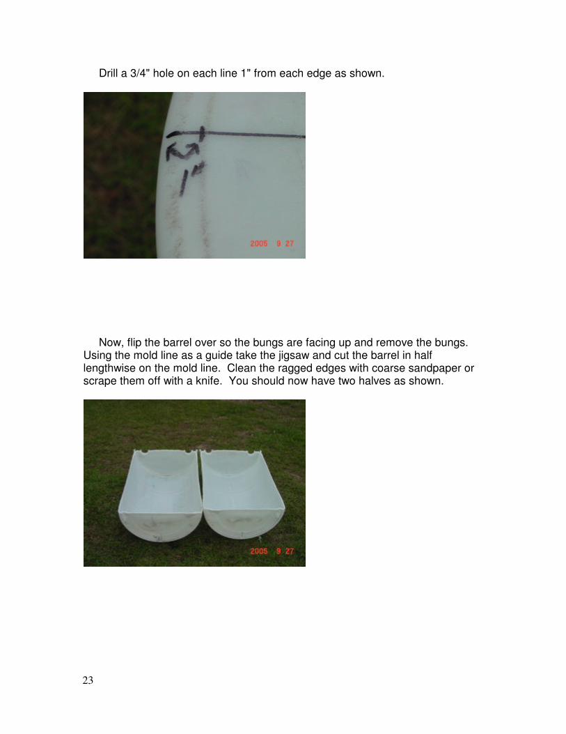
Drill a 3/4" hole on each line 1" from each edge as shown.
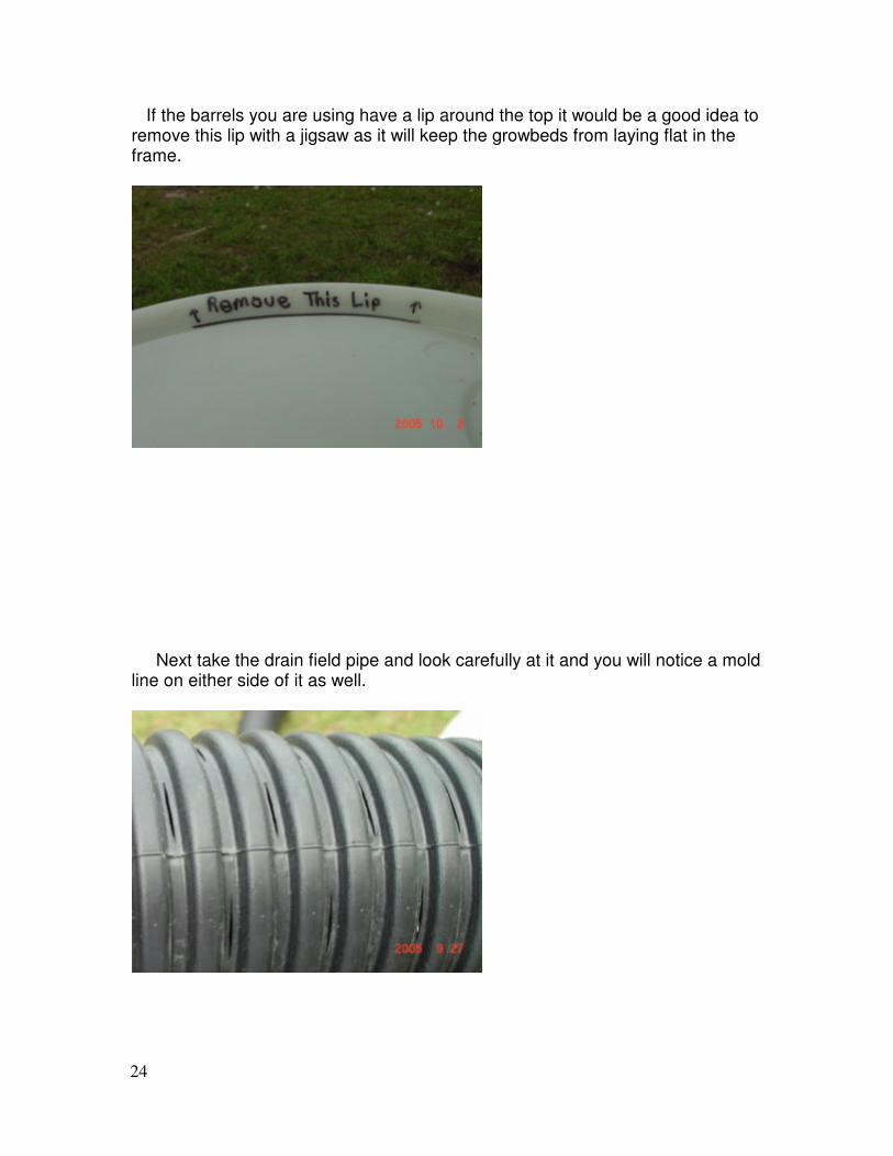
Now, flip the barrel over so the bungs are facing up and remove the bungs. Using the mold line as a guide take the jigsaw and cut the barrel in half lengthwise on the mold line. Clean the ragged edges with coarse sandpaper or scrape them off with a knife. You should now have two halves as shown.
24
If the barrels you are using have a lip around the top it would be a good idea to remove this lip with a jigsaw as it will keep the growbeds from laying flat in the frame.
Next take the drain field pipe and look carefully at it and you will notice a mold line on either side of it as well.
25
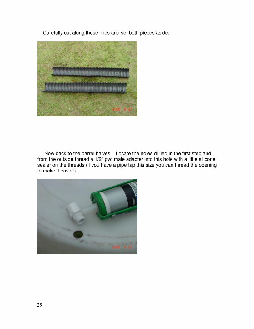
Carefully cut along these lines and set both pieces aside.
Now back to the barrel halves. Locate the holes drilled in the first step and from the outside thread a 1/2" pvc male adapter into this hole with a little silicone sealer on the threads (if you have a pipe tap this size you can thread the opening to make it easier).
26
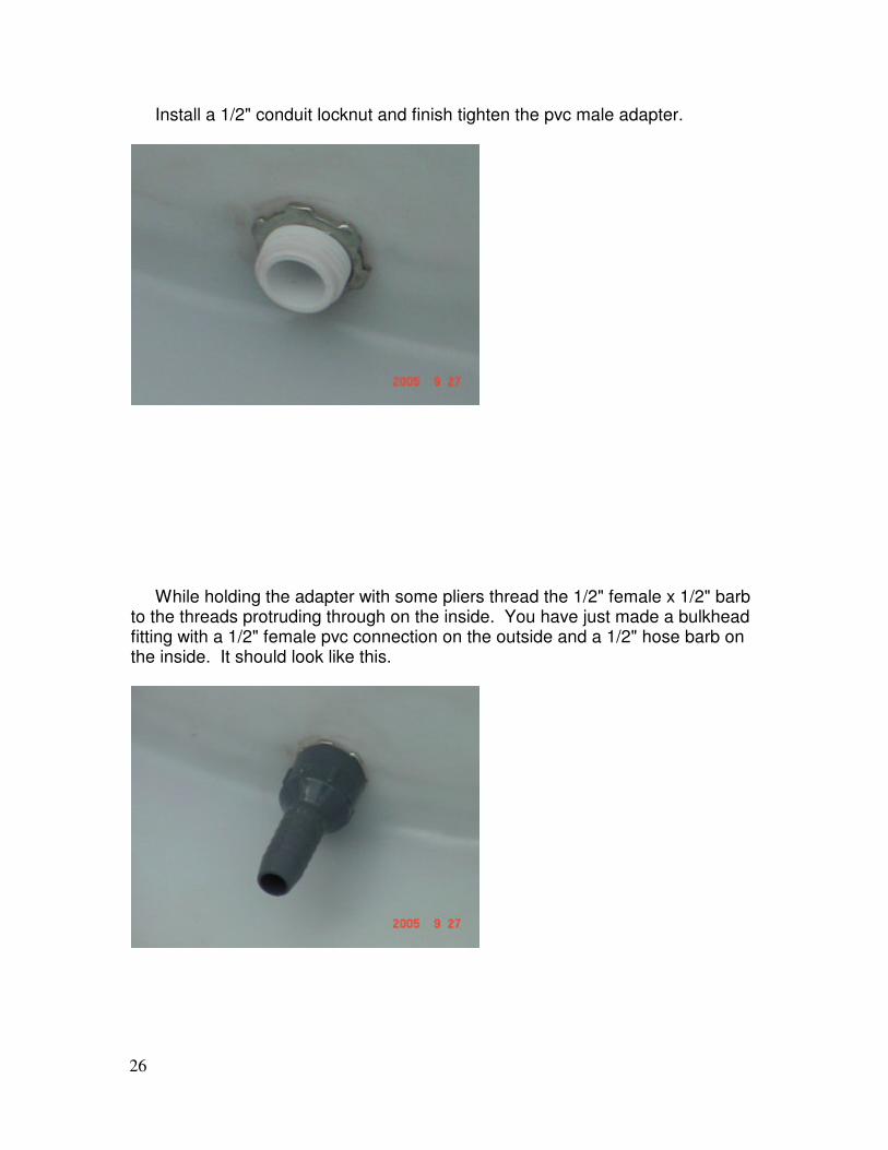
Install a 1/2" conduit locknut and finish tighten the pvc male adapter.
While holding the adapter with some pliers thread the 1/2" female x 1/2" barb to the threads protruding through on the inside. You have just made a bulkhead fitting with a 1/2" female pvc connection on the outside and a 1/2" hose barb on the inside. It should look like this.
27
Slip the short section of hose onto the barb and ensure the curve of the hose is turned down.
One half of the drain field pipe will go over this connection and run lengthwise on the bottom of the barrel half to create a clear water space for the siphon to draw water from. The end of the tube should contact the bottom of the grow bed. I have slightly heated and formed these tubes to get a better fit when necessary. Thoroughly clean the barrel halves with a good cleaner and then with vinegar to neutralize the soaps. A final cleaning with bleach water is also advised. We will determine the location of the overflow bypass fittings after the stand is built and gravel is in the beds.
28
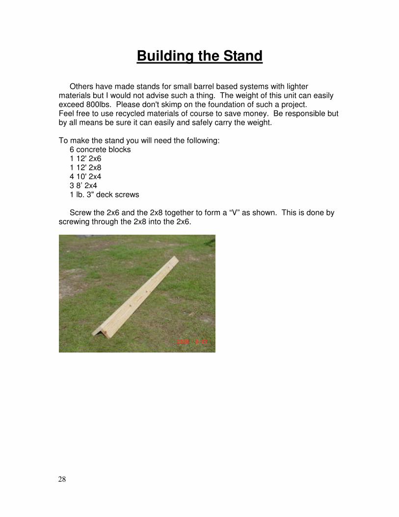
Building the Stand Others have made stands for small barrel based systems with lighter materials but I would not advise such a thing. The weight of this unit can easily exceed 800lbs. Please don't skimp on the foundation of such a project. Feel free to use recycled materials of course to save money. Be responsible but by all means be sure it can easily and safely carry the weight. To make the stand you will need the following: 6 concrete blocks 1 12' 2x6 1 12' 2x8 4 10' 2x4 3 8’ 2x4 1 lb. 3" deck screws Screw the 2x6 and the 2x8 together to form a “V” as shown. This is done by screwing through the 2x8 into the 2x6.
29
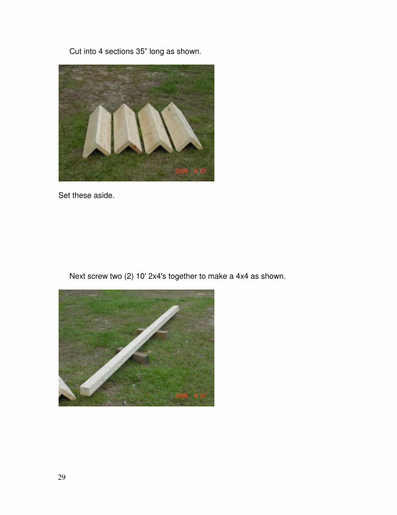
Cut into 4 sections 35” long as shown.
Set these aside. Next screw two (2) 10' 2x4's together to make a 4x4 as shown.

30
Cut this into two pieces 54-3/4" long.
Next position these pieces on the ground roughly 36" apart and set the two of the "V" pieces on top to form a rectangle as shown.
31
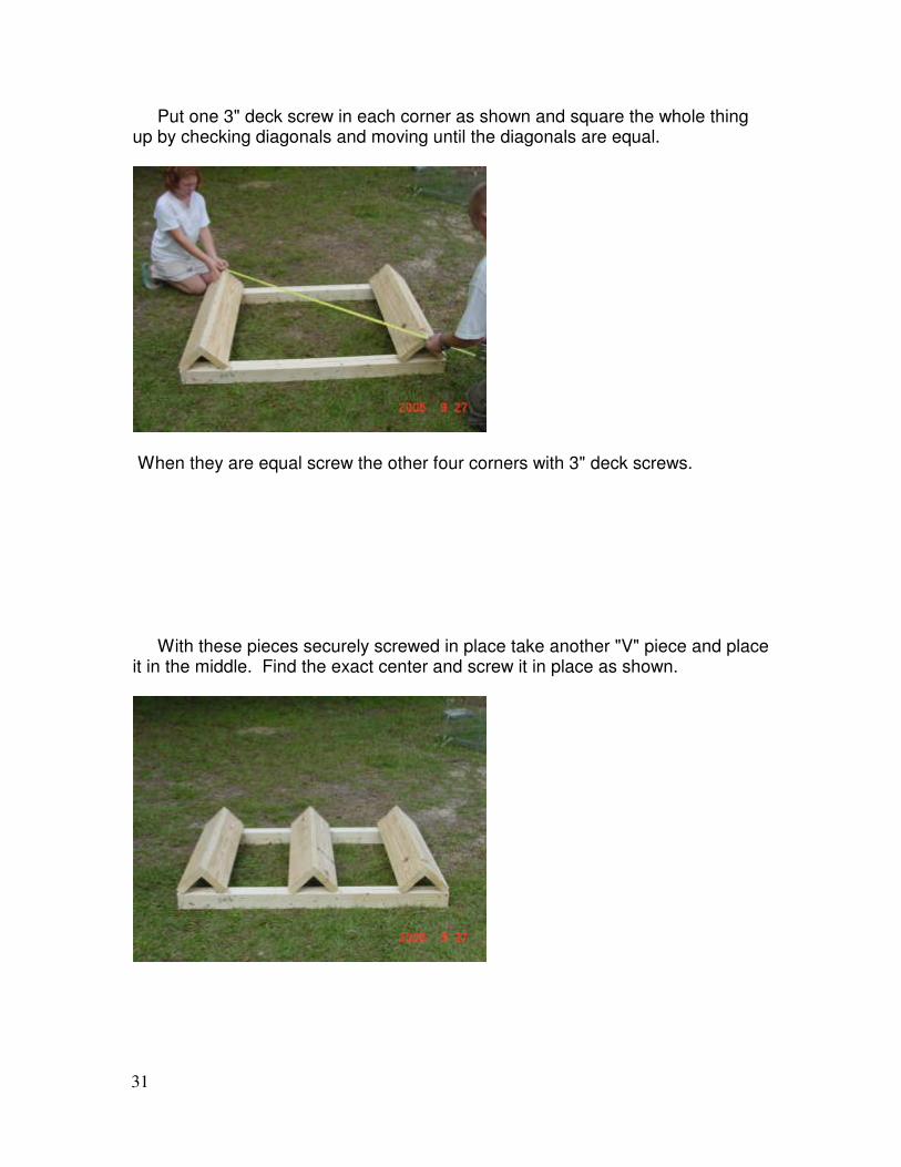
Put one 3" deck screw in each corner as shown and square the whole thing up by checking diagonals and moving until the diagonals are equal.
When they are equal screw the other four corners with 3" deck screws. With these pieces securely screwed in place take another "V" piece and place it in the middle. Find the exact center and screw it in place as shown.
32
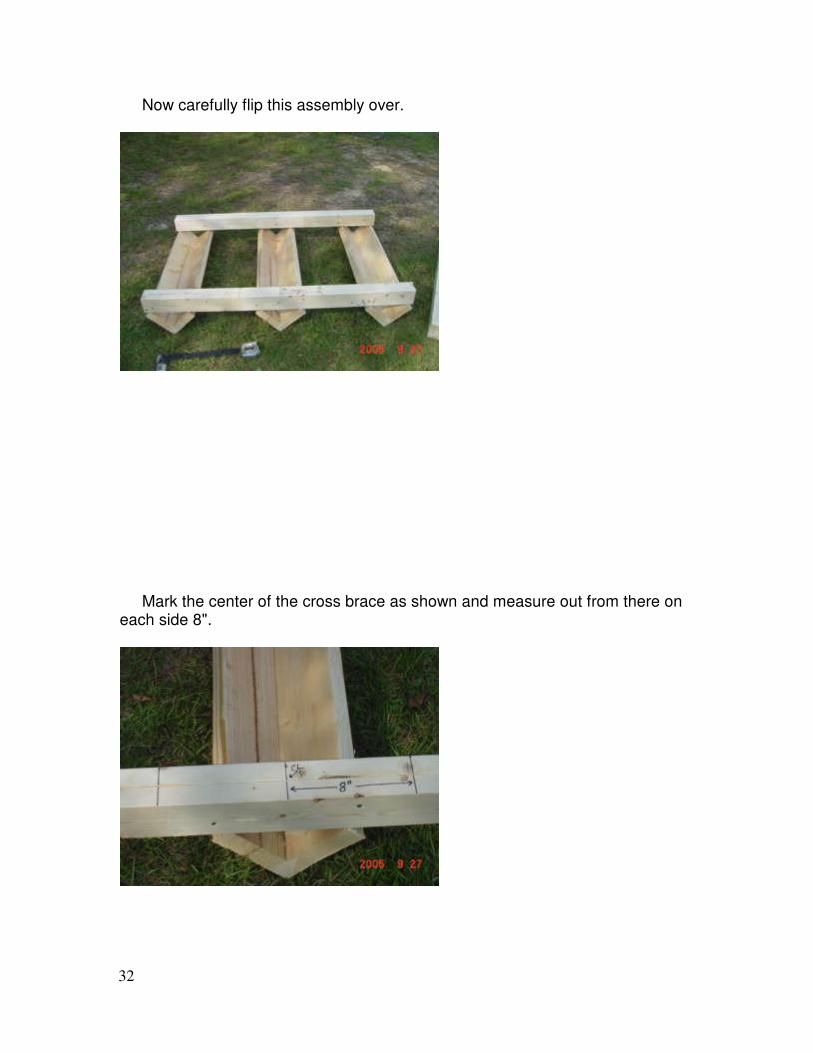
Now carefully flip this assembly over.
Mark the center of the cross brace as shown and measure out from there on each side 8".
33
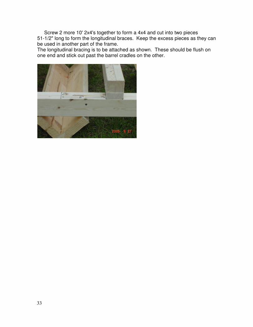
Screw 2 more 10' 2x4's together to form a 4x4 and cut into two pieces 51-1/2" long to form the longitudinal braces. Keep the excess pieces as they can be used in another part of the frame. The longitudinal bracing is to be attached as shown. These should be flush on one end and stick out past the barrel cradles on the other.
34
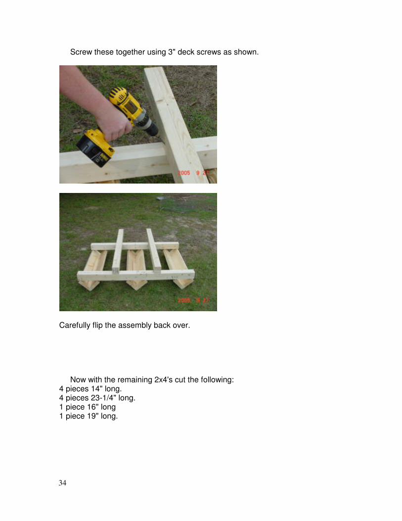
Screw these together using 3" deck screws as shown.
Carefully flip the assembly back over. Now with the remaining 2x4's cut the following: 4 pieces 14" long. 4 pieces 23-1/4" long. 1 piece 16" long 1 piece 19" long.
35
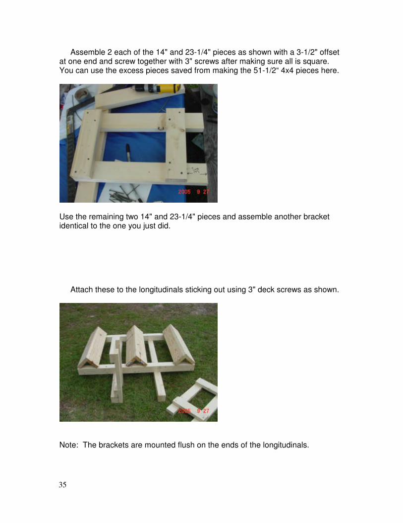
Assemble 2 each of the 14" and 23-1/4" pieces as shown with a 3-1/2" offset at one end and screw together with 3" screws after making sure all is square. You can use the excess pieces saved from making the 51-1/2“ 4x4 pieces here.
Use the remaining two 14" and 23-1/4" pieces and assemble another bracket identical to the one you just did. Attach these to the longitudinals sticking out using 3" deck screws as shown.
Note: The brackets are mounted flush on the ends of the longitudinals.
36
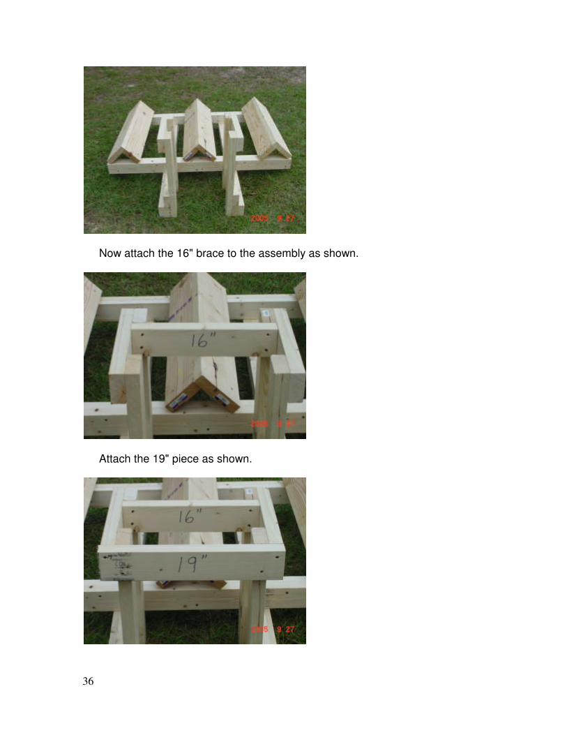
Now attach the 16" brace to the assembly as shown.
Attach the 19" piece as shown.
37
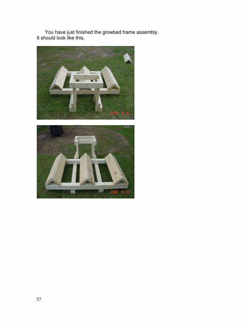
You have just finished the growbed frame assembly. It should look like this.
38
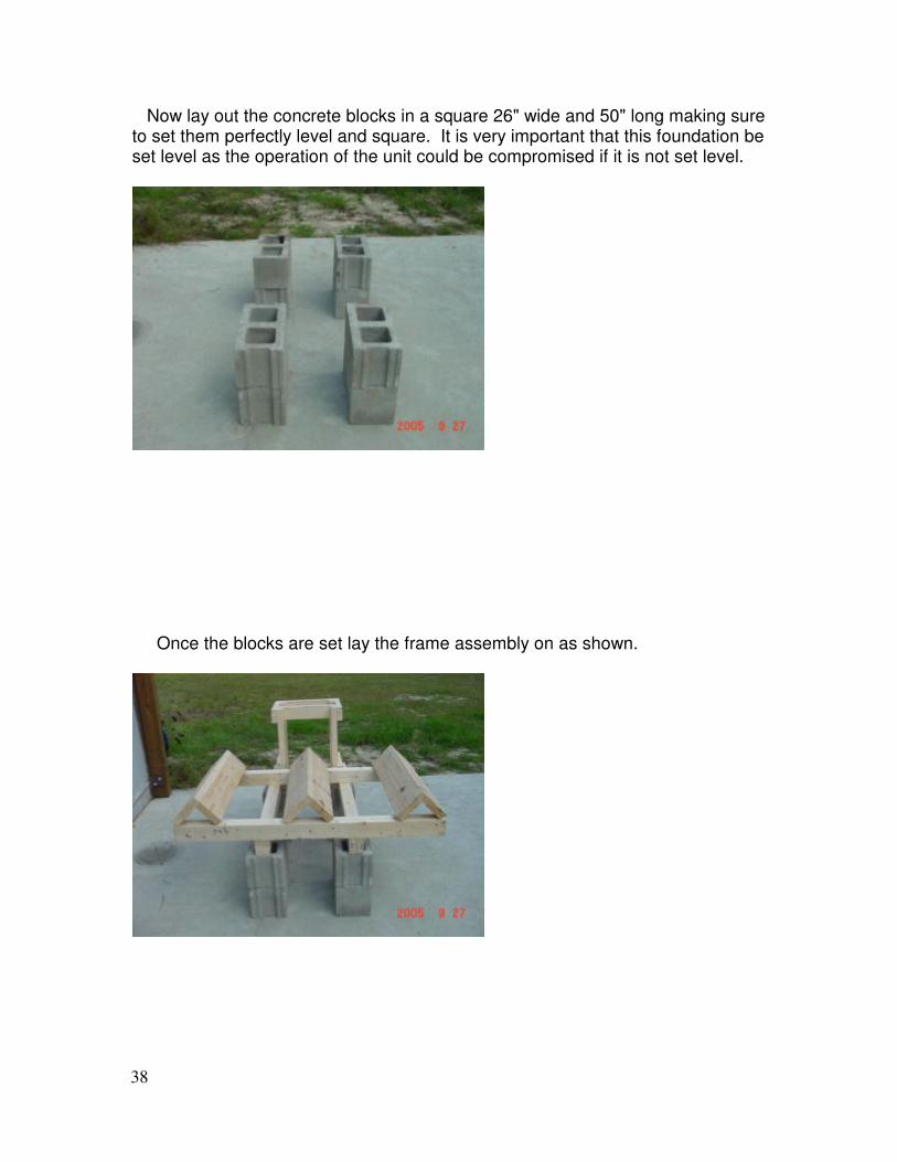
Now lay out the concrete blocks in a square 26" wide and 50" long making sure to set them perfectly level and square. It is very important that this foundation be set level as the operation of the unit could be compromised if it is not set level.
Once the blocks are set lay the frame assembly on as shown.
39
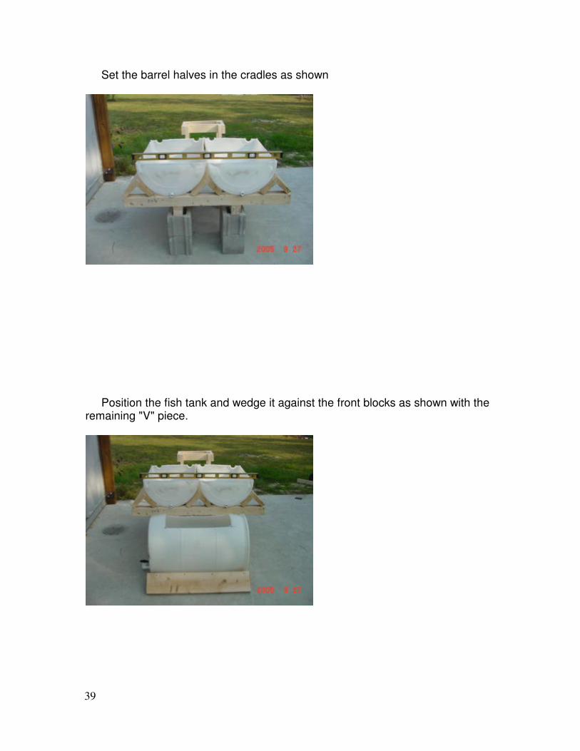
Set the barrel halves in the cradles as shown
Position the fish tank and wedge it against the front blocks as shown with the remaining "V" piece.
40
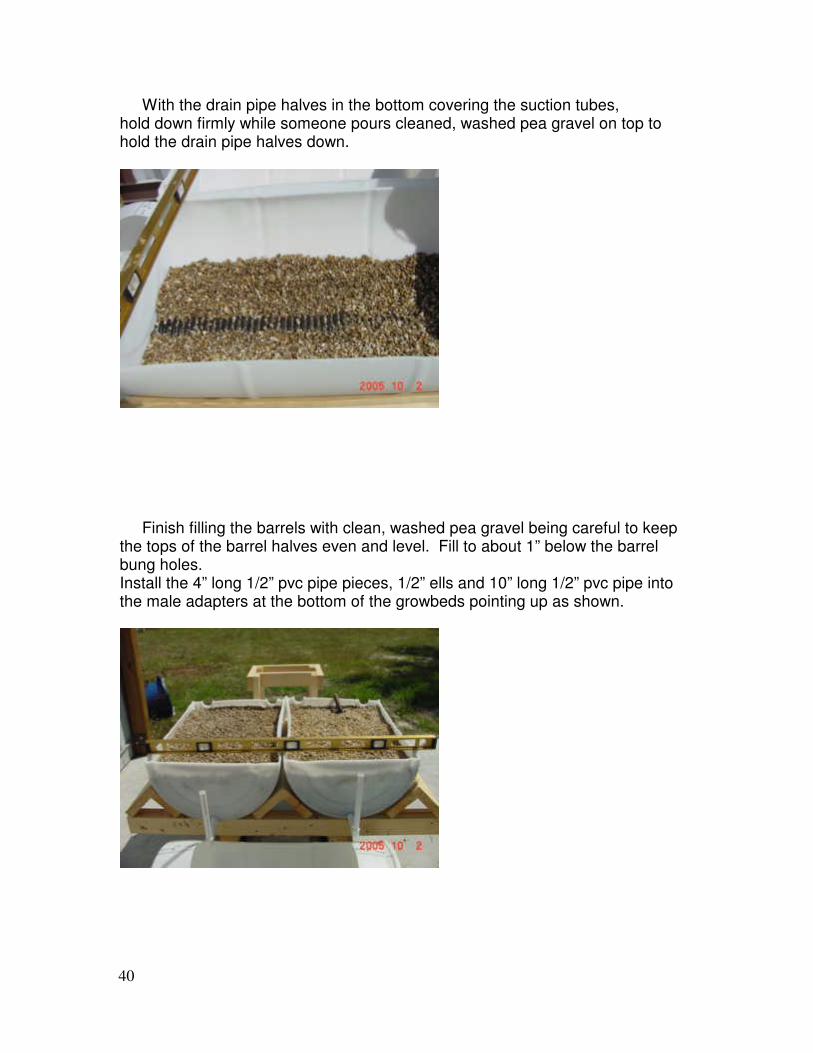
With the drain pipe halves in the bottom covering the suction tubes, hold down firmly while someone pours cleaned, washed pea gravel on top to hold the drain pipe halves down.
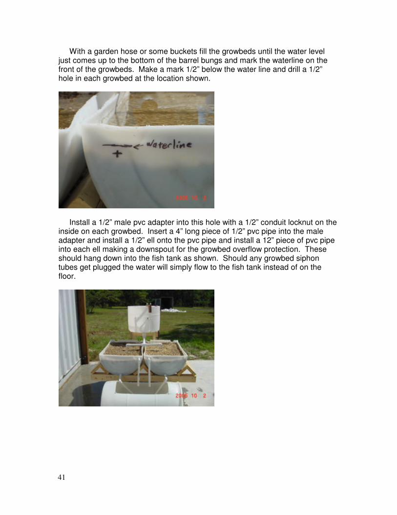
Finish filling the barrels with clean, washed pea gravel being careful to keep the tops of the barrel halves even and level. Fill to about 1” below the barrel bung holes. Install the 4” long 1/2” pvc pipe pieces, 1/2” ells and 10” long 1/2” pvc pipe into the male adapters at the bottom of the growbeds pointing up as shown.
41
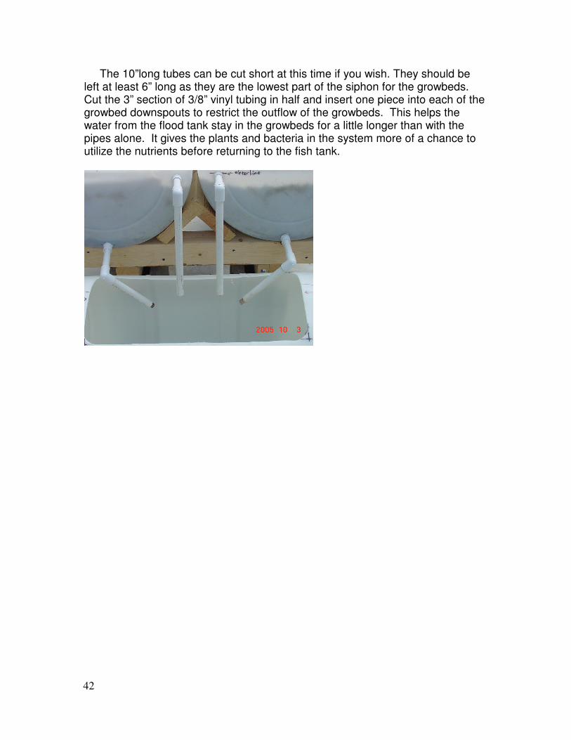
With a garden hose or some buckets fill the growbeds until the water level just comes up to the bottom of the barrel bungs and mark the waterline on the front of the growbeds. Make a mark 1/2” below the water line and drill a 1/2” hole in each growbed at the location shown.
Install a 1/2” male pvc adapter into this hole with a 1/2” conduit locknut on the inside on each growbed. Insert a 4” long piece of 1/2” pvc pipe into the male adapter and install a 1/2” ell onto the pvc pipe and install a 12” piece of pvc pipe into each ell making a downspout for the growbed overflow protection. These should hang down into the fish tank as shown. Should any growbed siphon tubes get plugged the water will simply flow to the fish tank instead of on the floor.
42
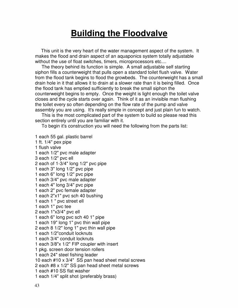
The 10”long tubes can be cut short at this time if you wish. They should be left at least 6” long as they are the lowest part of the siphon for the growbeds. Cut the 3” section of 3/8” vinyl tubing in half and insert one piece into each of the growbed downspouts to restrict the outflow of the growbeds. This helps the water from the flood tank stay in the growbeds for a little longer than with the pipes alone. It gives the plants and bacteria in the system more of a chance to utilize the nutrients before returning to the fish tank.
43
Building the Floodvalve
This unit is the very heart of the water management aspect of the system. It makes the flood and drain aspect of an aquaponics system totally adjustable without the use of float switches, timers, microprocessors etc.... The theory behind its function is simple. A small adjustable self starting siphon fills a counterweight that pulls open a standard toilet flush valve. Water from the flood tank begins to flood the growbeds. The counterweight has a small drain hole in it that allows it to drain at a slower rate than it is being filled. Once the flood tank has emptied sufficiently to break the small siphon the counterweight begins to empty. Once the weight is light enough the toilet valve closes and the cycle starts over again. Think of it as an invisible man flushing the toilet every so often depending on the flow rate of the pump and valve assembly you are using. It's really simple in concept and just plain fun to watch. This is the most complicated part of the system to build so please read this section entirely until you are familiar with it. To begin it's construction you will need the following from the parts list: 1 each 55 gal. plastic barrel 1 ft. 1/4" pex pipe 1 flush valve 1 each 1/2" pvc male adapter 3 each 1/2" pvc ell 2 each of 1-3/4" long 1/2" pvc pipe 1 each 3" long 1/2" pvc pipe 1 each 6" long 1/2" pvc pipe 1 each 3/4" pvc male adapter 1 each 4" long 3/4" pvc pipe 1 each 2" pvc female adapter 1 each 2"x1" pvc sch 40 bushing 1 each 1 " pvc street ell 1 each 1" pvc tee 2 each 1"x3/4" pvc ell 1 each 6" long pvc sch 40 1" pipe 1 each 19" long 1" pvc thin wall pipe 2 each 8 1/2" long 1" pvc thin wall pipe 1 each 1/2"conduit locknuts 1 each 3/4" conduit locknuts 1 each 3/8"x 1/2" FIP coupler with insert 1 pkg. screen door tension rollers 1 each 24" steel fishing leader 10 each #10 x 3/4" SS pan head sheet metal screws 2 each #8 x 1/2" SS pan head sheet metal screws 1 each #10 SS flat washer 1 each 1/4" split shot (preferably brass)
44
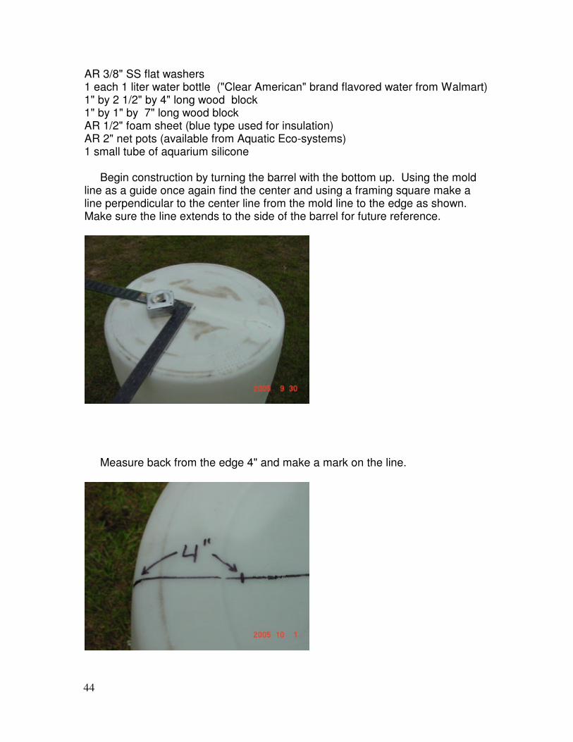
AR 3/8" SS flat washers 1 each 1 liter water bottle ("Clear American" brand flavored water from Walmart) 1" by 2 1/2" by 4" long wood block 1" by 1" by 7" long wood block AR 1/2" foam sheet (blue type used for insulation) AR 2" net pots (available from Aquatic Eco-systems) 1 small tube of aquarium silicone Begin construction by turning the barrel with the bottom up. Using the mold line as a guide once again find the center and using a framing square make a line perpendicular to the center line from the mold line to the edge as shown. Make sure the line extends to the side of the barrel for future reference.
Measure back from the edge 4" and make a mark on the line.
45
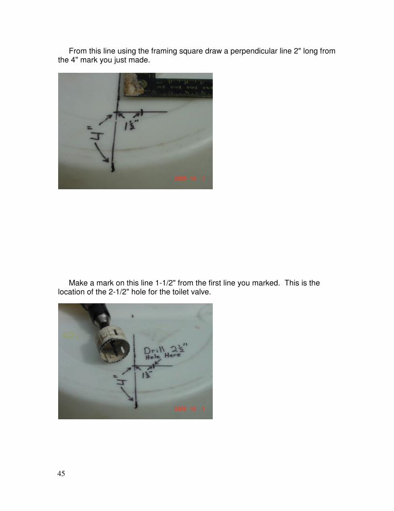
From this line using the framing square draw a perpendicular line 2" long from the 4" mark you just made.
Make a mark on this line 1-1/2" from the first line you marked. This is the location of the 2-1/2" hole for the toilet valve.
46
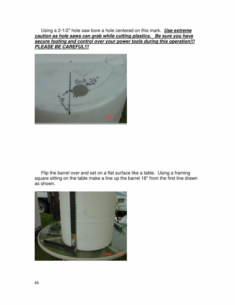
Using a 2-1/2" hole saw bore a hole centered on this mark. Use extreme caution as hole saws can grab while cutting plastics. Be sure you have secure footing and control over your power tools during this operation!!! PLEASE BE CAREFUL!!!
Flip the barrel over and set on a flat surface like a table. Using a framing square sitting on the table make a line up the barrel 18" from the first line drawn as shown.
47
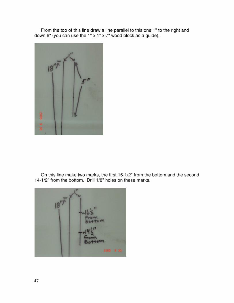
From the top of this line draw a line parallel to this one 1" to the right and down 6" (you can use the 1" x 1" x 7" wood block as a guide).
On this line make two marks, the first 16-1/2" from the bottom and the second 14-1/2" from the bottom. Drill 1/8" holes on these marks.
48
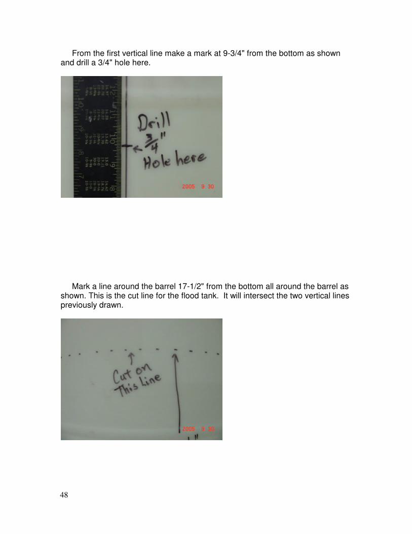
From the first vertical line make a mark at 9-3/4" from the bottom as shown and drill a 3/4" hole here.
Mark a line around the barrel 17-1/2" from the bottom all around the barrel as shown. This is the cut line for the flood tank. It will intersect the two vertical lines previously drawn.
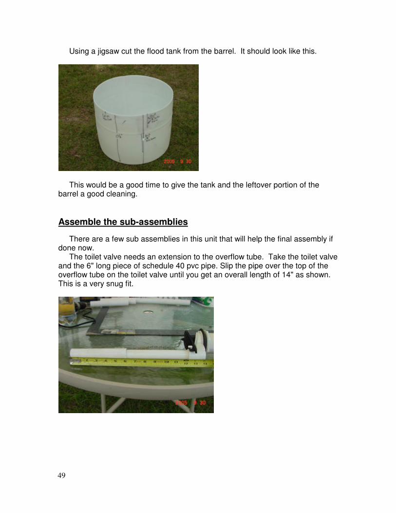
49
Using a jigsaw cut the flood tank from the barrel. It should look like this.
This would be a good time to give the tank and the leftover portion of the barrel a good cleaning.
Assemble the sub-assemblies
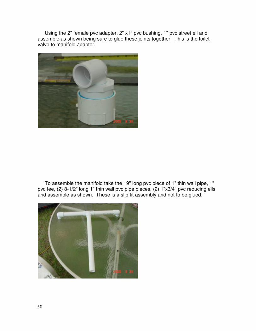
There are a few sub assemblies in this unit that will help the final assembly if done now. The toilet valve needs an extension to the overflow tube. Take the toilet valve and the 6" long piece of schedule 40 pvc pipe. Slip the pipe over the top of the overflow tube on the toilet valve until you get an overall length of 14" as shown. This is a very snug fit.
50
Using the 2" female pvc adapter, 2" x1" pvc bushing, 1" pvc street ell and assemble as shown being sure to glue these joints together. This is the toilet valve to manifold adapter.
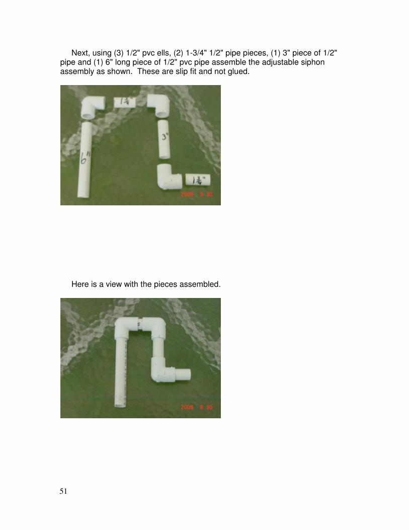
To assemble the manifold take the 19" long pvc piece of 1" thin wall pipe, 1" pvc tee, (2) 8-1/2" long 1" thin wall pvc pipe pieces, (2) 1"x3/4" pvc reducing ells and assemble as shown. These is a slip fit assembly and not to be glued.
51
Next, using (3) 1/2" pvc ells, (2) 1-3/4" 1/2" pipe pieces, (1) 3" piece of 1/2" pipe and (1) 6" long piece of 1/2" pvc pipe assemble the adjustable siphon assembly as shown. These are slip fit and not glued.
Here is a view with the pieces assembled.
52
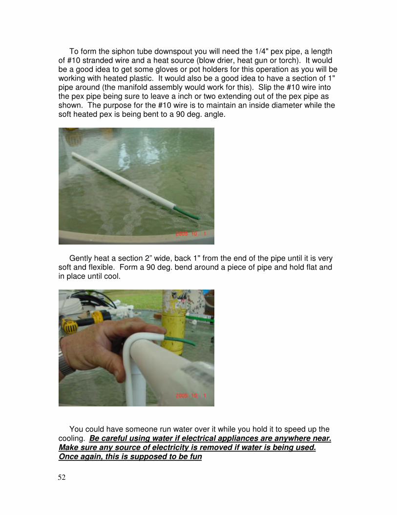
To form the siphon tube downspout you will need the 1/4" pex pipe, a length of #10 stranded wire and a heat source (blow drier, heat gun or torch). It would be a good idea to get some gloves or pot holders for this operation as you will be working with heated plastic. It would also be a good idea to have a section of 1" pipe around (the manifold assembly would work for this). Slip the #10 wire into the pex pipe being sure to leave a inch or two extending out of the pex pipe as shown. The purpose for the #10 wire is to maintain an inside diameter while the soft heated pex is being bent to a 90 deg. angle.
Gently heat a section 2” wide, back 1" from the end of the pipe until it is very soft and flexible. Form a 90 deg. bend around a piece of pipe and hold flat and in place until cool.
You could have someone run water over it while you hold it to speed up the cooling. Be careful using water if electrical appliances are anywhere near. Make sure any source of electricity is removed if water is being used. Once again, this is supposed to be fun
53
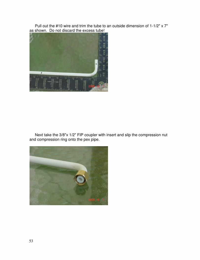
Pull out the #10 wire and trim the tube to an outside dimension of 1-1/2" x 7" as shown. Do not discard the excess tube!
Next take the 3/8"x 1/2" FIP coupler with insert and slip the compression nut and compression ring onto the pex pipe.
54
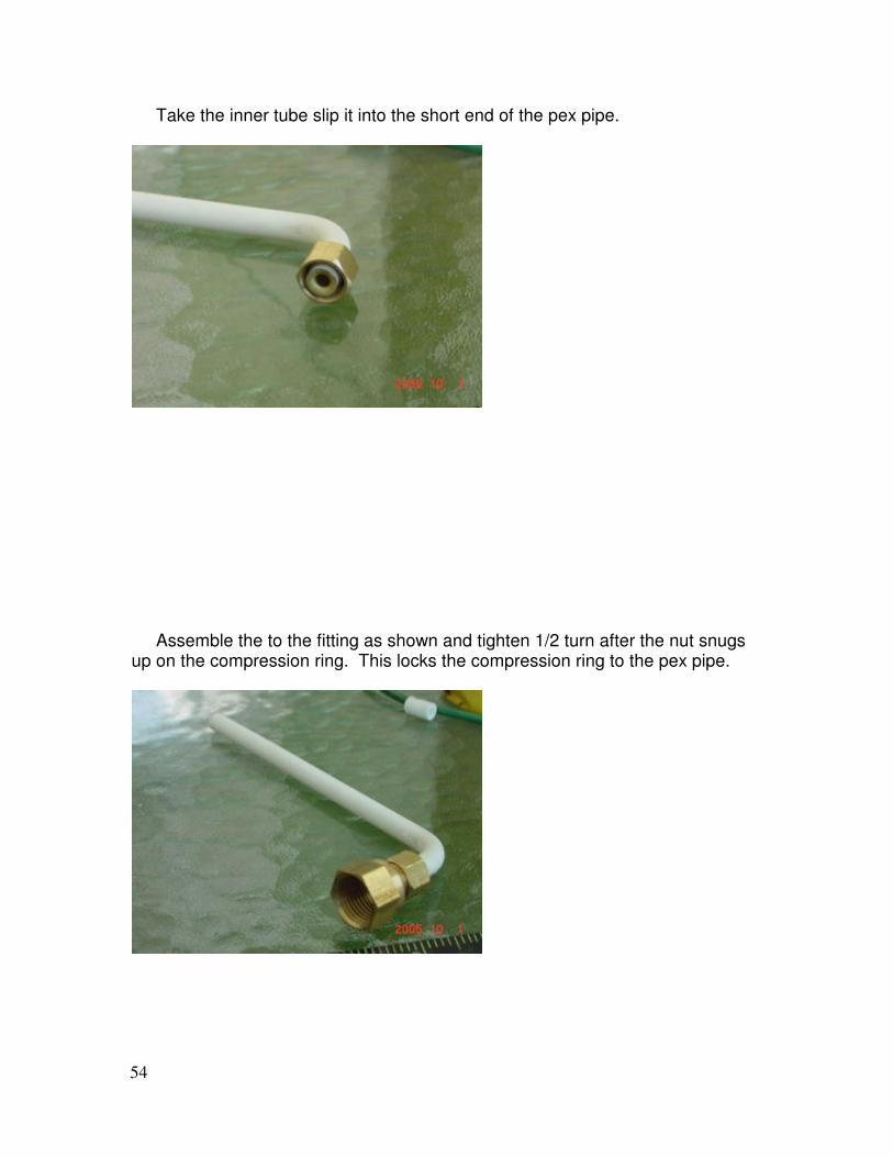
Take the inner tube slip it into the short end of the pex pipe.
Assemble the to the fitting as shown and tighten 1/2 turn after the nut snugs up on the compression ring. This locks the compression ring to the pex pipe.

55
Disassemble the unit and remove the brass insert. Leaving it in place will restrict water flow through this tube.
Reassemble the compression fitting finger tight for now and set aside.
56
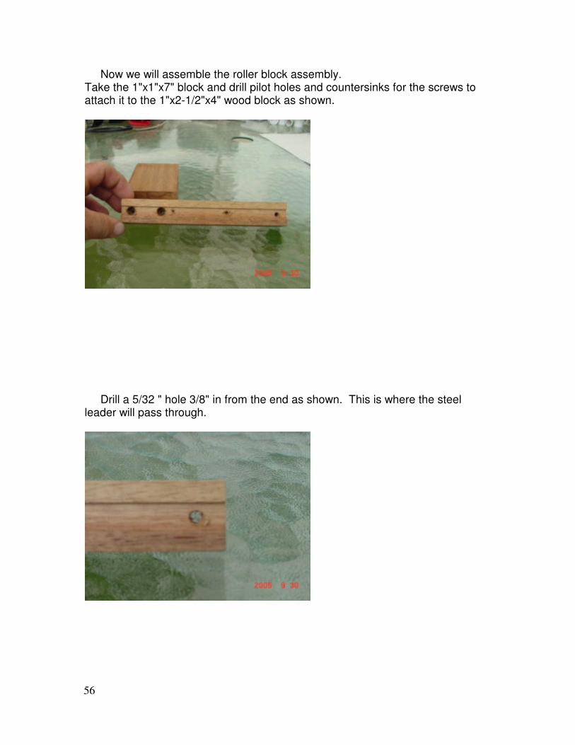
Now we will assemble the roller block assembly. Take the 1"x1"x7" block and drill pilot holes and countersinks for the screws to attach it to the 1"x2-1/2"x4" wood block as shown.
Drill a 5/32 " hole 3/8" in from the end as shown. This is where the steel leader will pass through.
57
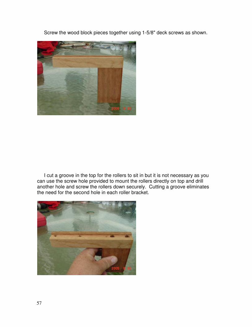
Screw the wood block pieces together using 1-5/8" deck screws as shown.
I cut a groove in the top for the rollers to sit in but it is not necessary as you can use the screw hole provided to mount the rollers directly on top and drill another hole and screw the rollers down securely. Cutting a groove eliminates the need for the second hole in each roller bracket.
58
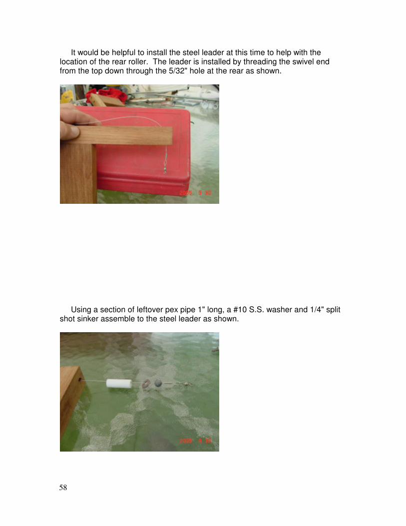
It would be helpful to install the steel leader at this time to help with the location of the rear roller. The leader is installed by threading the swivel end from the top down through the 5/32" hole at the rear as shown.
Using a section of leftover pex pipe 1" long, a #10 S.S. washer and 1/4" split shot sinker assemble to the steel leader as shown.
59
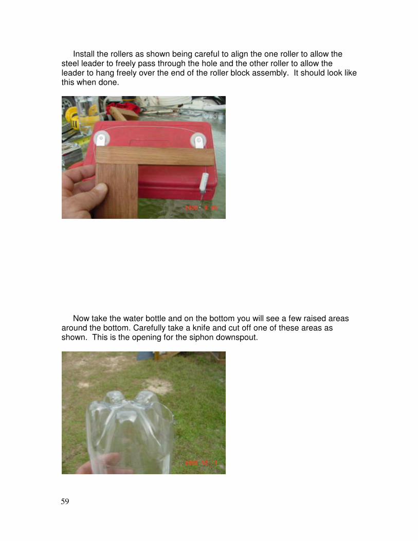
Install the rollers as shown being careful to align the one roller to allow the steel leader to freely pass through the hole and the other roller to allow the leader to hang freely over the end of the roller block assembly. It should look like this when done.
Now take the water bottle and on the bottom you will see a few raised areas around the bottom. Carefully take a knife and cut off one of these areas as shown. This is the opening for the siphon downspout.
60
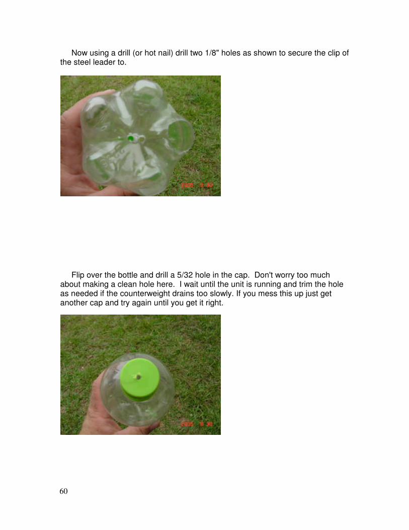
Now using a drill (or hot nail) drill two 1/8" holes as shown to secure the clip of the steel leader to.
Flip over the bottle and drill a 5/32 hole in the cap. Don't worry too much about making a clean hole here. I wait until the unit is running and trim the hole as needed if the counterweight drains too slowly. If you mess this up just get another cap and try again until you get it right.
61
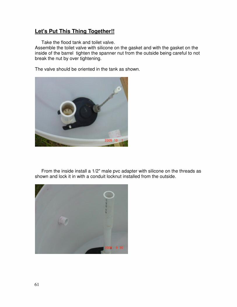
Let's Put This Thing Together!! Take the flood tank and toilet valve. Assemble the toilet valve with silicone on the gasket and with the gasket on the inside of the barrel tighten the spanner nut from the outside being careful to not break the nut by over tightening. The valve should be oriented in the tank as shown.
From the inside install a 1/2" male pvc adapter with silicone on the threads as shown and lock it in with a conduit locknut installed from the outside.
62
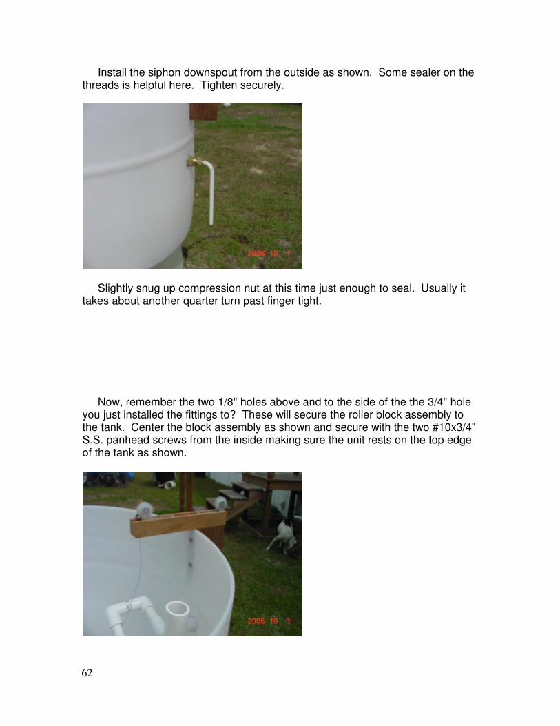
Install the siphon downspout from the outside as shown. Some sealer on the threads is helpful here. Tighten securely.
Slightly snug up compression nut at this time just enough to seal. Usually it takes about another quarter turn past finger tight. Now, remember the two 1/8" holes above and to the side of the the 3/4" hole you just installed the fittings to? These will secure the roller block assembly to the tank. Center the block assembly as shown and secure with the two #10x3/4" S.S. panhead screws from the inside making sure the unit rests on the top edge of the tank as shown.
63
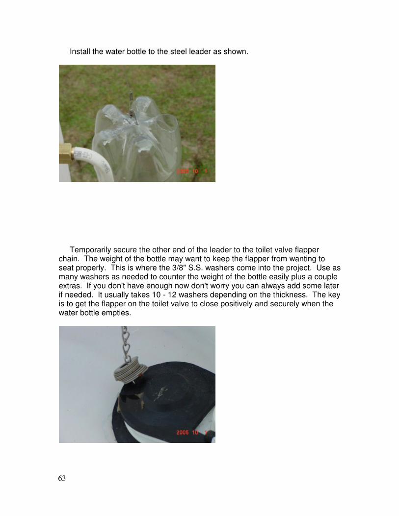
Install the water bottle to the steel leader as shown.
Temporarily secure the other end of the leader to the toilet valve flapper chain. The weight of the bottle may want to keep the flapper from wanting to seat properly. This is where the 3/8" S.S. washers come into the project. Use as many washers as needed to counter the weight of the bottle easily plus a couple extras. If you don't have enough now don't worry you can always add some later if needed. It usually takes 10 - 12 washers depending on the thickness. The key is to get the flapper on the toilet valve to close positively and securely when the water bottle empties.
64
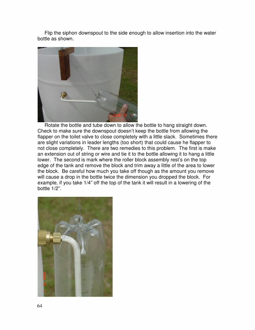
Flip the siphon downspout to the side enough to allow insertion into the water bottle as shown.
Rotate the bottle and tube down to allow the bottle to hang straight down. Check to make sure the downspout doesn’t keep the bottle from allowing the flapper on the toilet valve to close completely with a little slack. Sometimes there are slight variations in leader lengths (too short) that could cause he flapper to not close completely. There are two remedies to this problem. The first is make an extension out of string or wire and tie it to the bottle allowing it to hang a little lower. The second is mark where the roller block assembly rest’s on the top edge of the tank and remove the block and trim away a little of the area to lower the block. Be careful how much you take off though as the amount you remove will cause a drop in the bottle twice the dimension you dropped the block. For example, if you take 1/4” off the top of the tank it will result in a lowering of the bottle 1/2”.
65
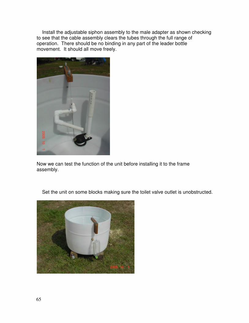
Install the adjustable siphon assembly to the male adapter as shown checking to see that the cable assembly clears the tubes through the full range of operation. There should be no binding in any part of the leader bottle movement. It should all move freely.
Now we can test the function of the unit before installing it to the frame assembly. Set the unit on some blocks making sure the toilet valve outlet is unobstructed.
66
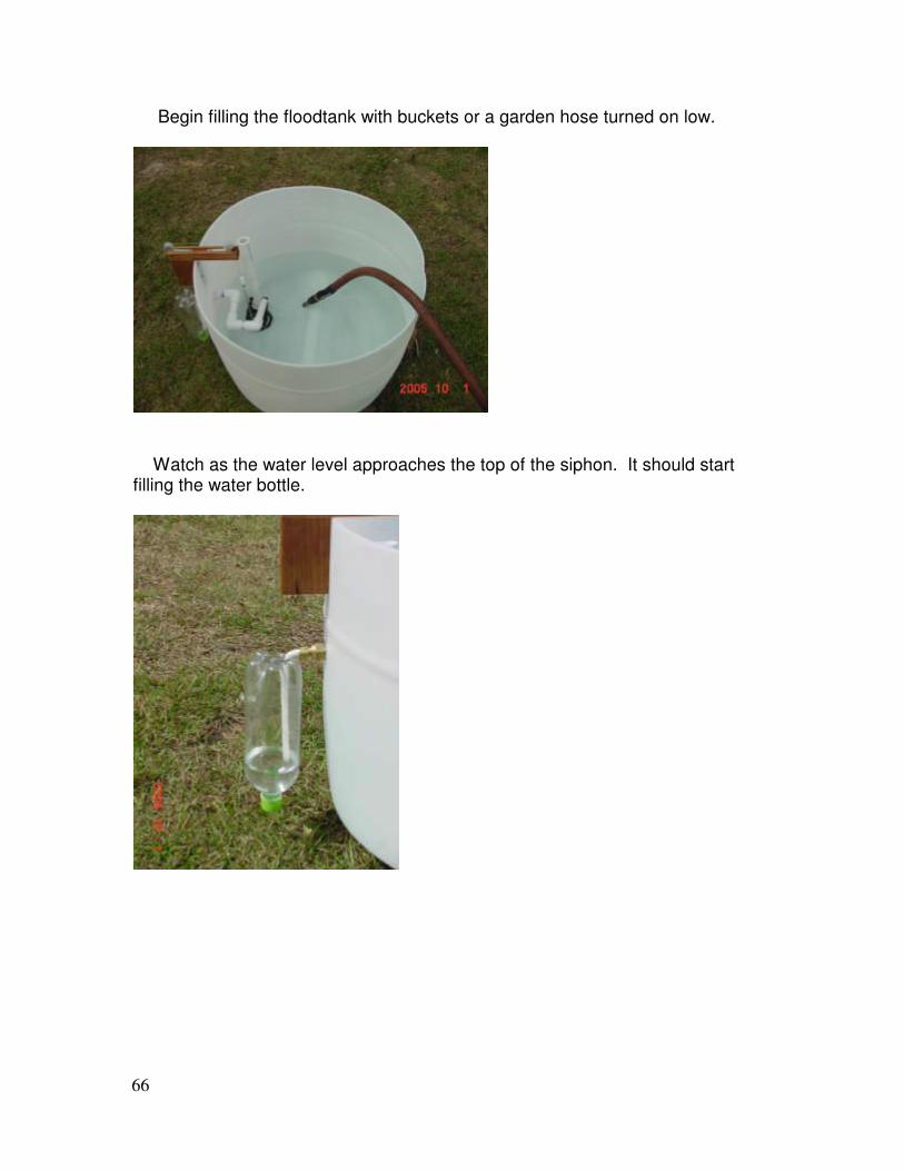
Begin filling the floodtank with buckets or a garden hose turned on low.
Watch as the water level approaches the top of the siphon. It should start filling the water bottle.
67
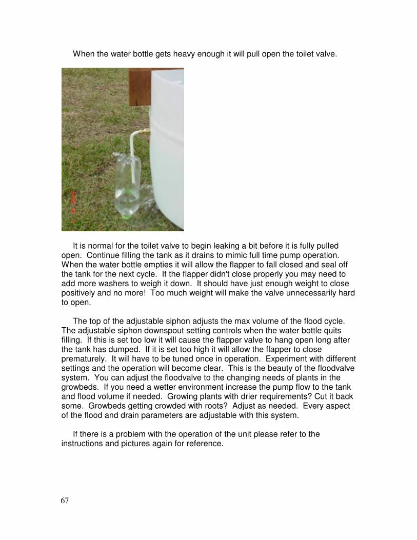
When the water bottle gets heavy enough it will pull open the toilet valve.
It is normal for the toilet valve to begin leaking a bit before it is fully pulled open. Continue filling the tank as it drains to mimic full time pump operation. When the water bottle empties it will allow the flapper to fall closed and seal off the tank for the next cycle. If the flapper didn't close properly you may need to add more washers to weigh it down. It should have just enough weight to close positively and no more! Too much weight will make the valve unnecessarily hard to open. The top of the adjustable siphon adjusts the max volume of the flood cycle. The adjustable siphon downspout setting controls when the water bottle quits filling. If this is set too low it will cause the flapper valve to hang open long after the tank has dumped. If it is set too high it will allow the flapper to close prematurely. It will have to be tuned once in operation. Experiment with different settings and the operation will become clear. This is the beauty of the floodvalve system. You can adjust the floodvalve to the changing needs of plants in the growbeds. If you need a wetter environment increase the pump flow to the tank and flood volume if needed. Growing plants with drier requirements? Cut it back some. Growbeds getting crowded with roots? Adjust as needed. Every aspect of the flood and drain parameters are adjustable with this system. If there is a problem with the operation of the unit please refer to the instructions and pictures again for reference.
68
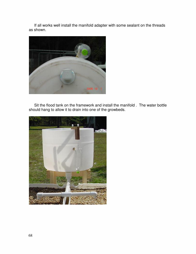
If all works well install the manifold adapter with some sealant on the threads as shown.
Sit the flood tank on the framework and install the manifold . The water bottle should hang to allow it to drain into one of the growbeds.
69
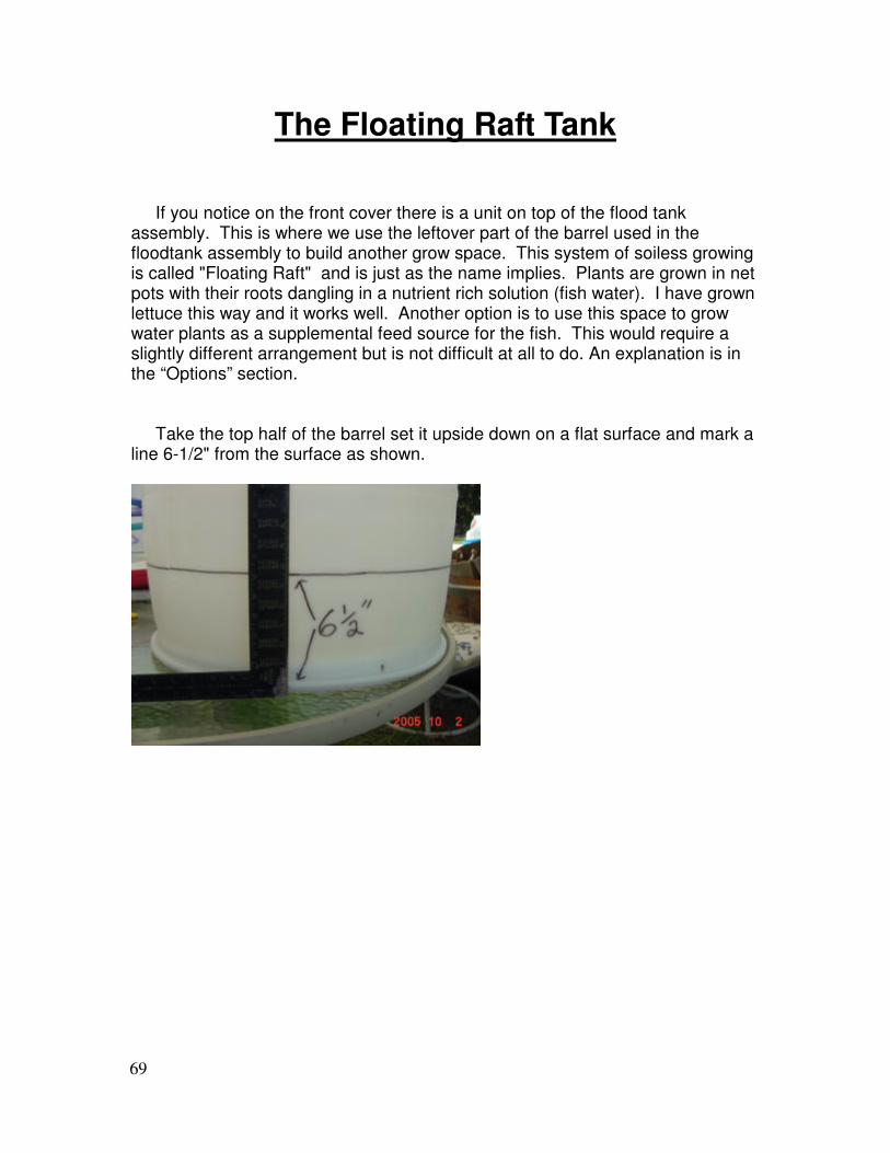
The Floating Raft Tank If you notice on the front cover there is a unit on top of the flood tank assembly. This is where we use the leftover part of the barrel used in the floodtank assembly to build another grow space. This system of soiless growing is called "Floating Raft" and is just as the name implies. Plants are grown in net pots with their roots dangling in a nutrient rich solution (fish water). I have grown lettuce this way and it works well. Another option is to use this space to grow water plants as a supplemental feed source for the fish. This would require a slightly different arrangement but is not difficult at all to do. An explanation is in the “Options” section. Take the top half of the barrel set it upside down on a flat surface and mark a line 6-1/2" from the surface as shown.

70
Cut the barrel here to make a shallow tank and drill a 1" hole about three inches in from the edge where the top is flat as shown. The actual distance is not all that critical as this is merely a standpipe to set the water level in the the tank.
Install a 3/4" pvc male adapter from the inside and slip the 4" long pvc sch. 40 into it.
71
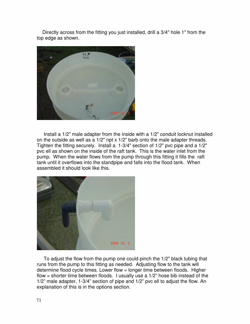
Directly across from the fitting you just installed, drill a 3/4" hole 1" from the top edge as shown.
Install a 1/2" male adapter from the inside with a 1/2" conduit locknut installed on the outside as well as a 1/2" npt x 1/2" barb onto the male adapter threads. Tighten the fitting securely. Install a 1-3/4" section of 1/2" pvc pipe and a 1/2" pvc ell as shown on the inside of the raft tank. This is the water inlet from the pump. When the water flows from the pump through this fitting it fills the raft tank until it overflows into the standpipe and falls into the flood tank. When assembled it should look like this.
To adjust the flow from the pump one could pinch the 1/2" black tubing that runs from the pump to this fitting as needed. Adjusting flow to the tank will determine flood cycle times. Lower flow = longer time between floods. Higher flow = shorter time between floods. I usually use a 1/2” hose bib instead of the 1/2” male adapter, 1-3/4” section of pipe and 1/2” pvc ell to adjust the flow. An explanation of this is in the options section.
72
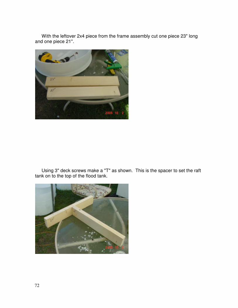
With the leftover 2x4 piece from the frame assembly cut one piece 23" long and one piece 21".
Using 3" deck screws make a "T" as shown. This is the spacer to set the raft tank on to the top of the flood tank.
73
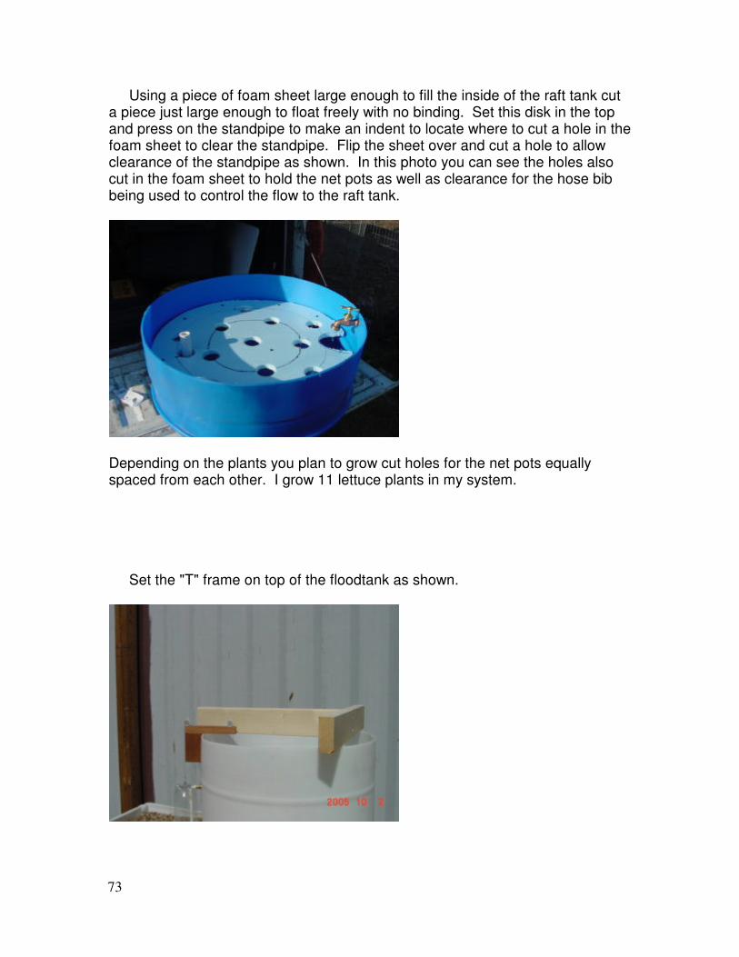
Using a piece of foam sheet large enough to fill the inside of the raft tank cut a piece just large enough to float freely with no binding. Set this disk in the top and press on the standpipe to make an indent to locate where to cut a hole in the foam sheet to clear the standpipe. Flip the sheet over and cut a hole to allow clearance of the standpipe as shown. In this photo you can see the holes also cut in the foam sheet to hold the net pots as well as clearance for the hose bib being used to control the flow to the raft tank.
Depending on the plants you plan to grow cut holes for the net pots equally spaced from each other. I grow 11 lettuce plants in my system. Set the "T" frame on top of the floodtank as shown.
74
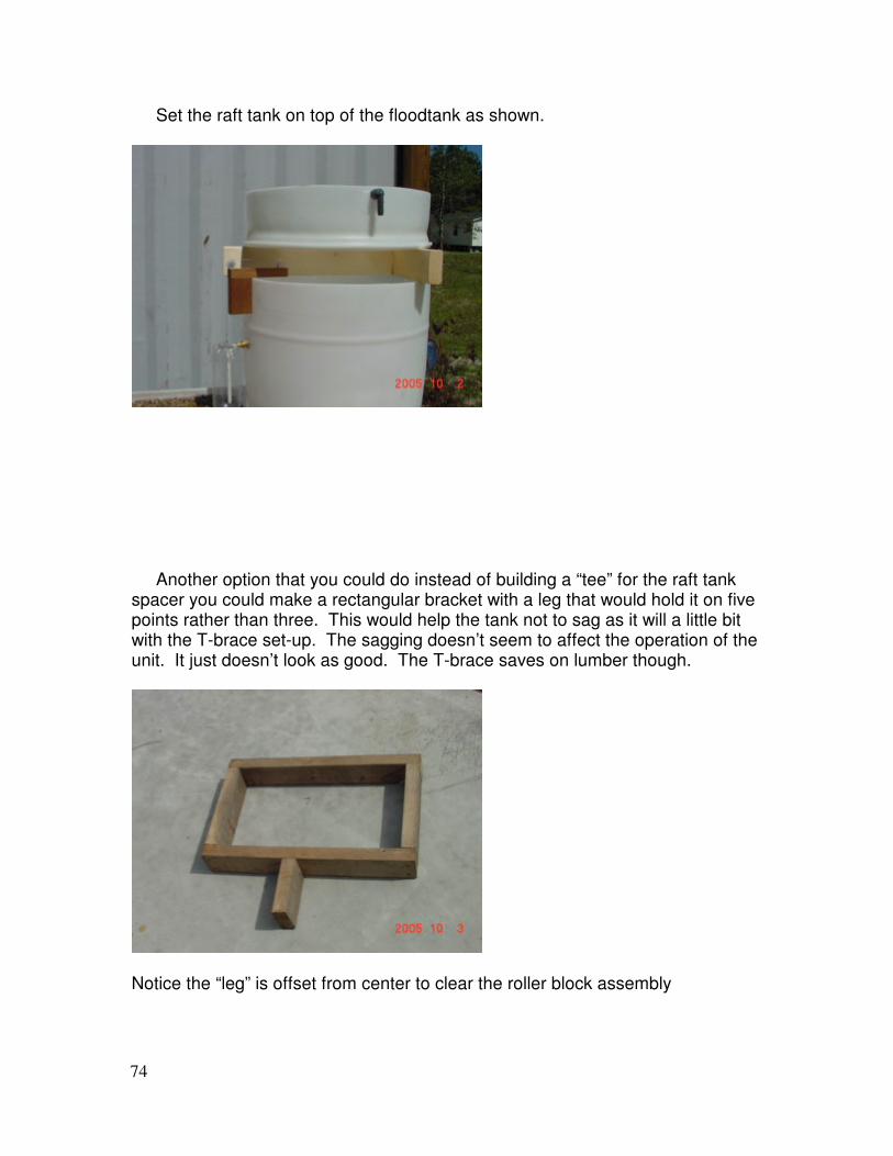
Set the raft tank on top of the floodtank as shown.
Another option that you could do instead of building a “tee” for the raft tank spacer you could make a rectangular bracket with a leg that would hold it on five points rather than three. This would help the tank not to sag as it will a little bit with the T-brace set-up. The sagging doesn’t seem to affect the operation of the unit. It just doesn’t look as good. The T-brace saves on lumber though.
Notice the “leg” is offset from center to clear the roller block assembly
75
Movin' the Water
Now for a word about pumps and such. If you have electric pumps available to you, you will need a pump capable of at least 60 gph at a 7' head (the system will run on as little as 40 gph but you will want to aerate some water). What does all this mean? Most pump capacities you see in the big print on the package is at 0 ft. head. This means if you see a pump rated at 400 gph it probably won't begin to push the water to the 7' required to operate this system. Bilge pumps are a bit of an exception to this rule as they are expected to lift water to at least three feet and are rated to do so. You will need to look in the packaging of the pump and read the chart to find out what the max. head is and the flow at that head. We are not really concerned with pressure at a certain lift, just volume of water in gph. That being said, the 60 gph is a bare minimum and if you are wanting to get the most performance out of your system please don't skimp here. I have used very small pumps to run this system in tests and they do work but require constant cleaning and flushing of the tubing to keep things working. It is also very hard for a pump to be working at maximum for long period of time and keep the reliability high. Try to size a pump that will be work at about 60% or less (even better) of it's rated output for a good reliable system as it will be running continuous. There are several different pump types out there but you will find centrifugal pumps will be the best for this type of use. Submersible pumps are fine however I prefer to have things out where I can maintain them easily. I also prefer to use magnetic drive pumps because the motor continues to run even if the impeller gets clogged with debris. This type of pump is also nice when it comes time to replace a worn out pump as you can get replacement heads and reuse the motor. The type of pump I have had the best success by far with is the type used in marine air conditioning systems. They are a variety of manufacturers and all of them are good. Sometimes I find good deals on ebay as these are typically very expensive ($300.00 and up new). Some marinas have some rebuildable ones in their junk pile that have good motors but the pump section is worn out. Just order a replacement pump kit and you are as good as new. As far as 12V bilge or baitwell pumps go, I have used them successfully but they have a weakness. Debris that can get sucked up into the impeller can stop the pump and will blow the fuse and shut the system down. If this happens often it will eventually burn out the pump. One way to avoid this is to use some type of strainer or pre-filter to keep the debris out. One word of wisdom though, these pumps are not designed to be used full time and will on average fail faster than a pump designed for continuous use. However, they tend to be very inexpensive compared to the some options and could be a good choice for a 12VDC system if a better pump is not available. They will just need to be replaced more often. Another option for a 12VDC system would be to use a magnetic type baitwell pump. They are more expensive but should live longer. Look very closely at the spec. sheet though to determine if the pump will have the output needed. This system by no means is limited to electric pumps. That's the beauty of
76
the flood valve. Any method that can reliably move the water can be used. Some examples are solar panels hooked to 12V pumps, wind power (either directly driving a pump or using wind to generate power), using a water wheel in a flowing stream to drive a circulation pump, gas or diesel powered pumps (for larger applications) even human or animal powered pumps would work. The limit is your or your neighbors imagination!!
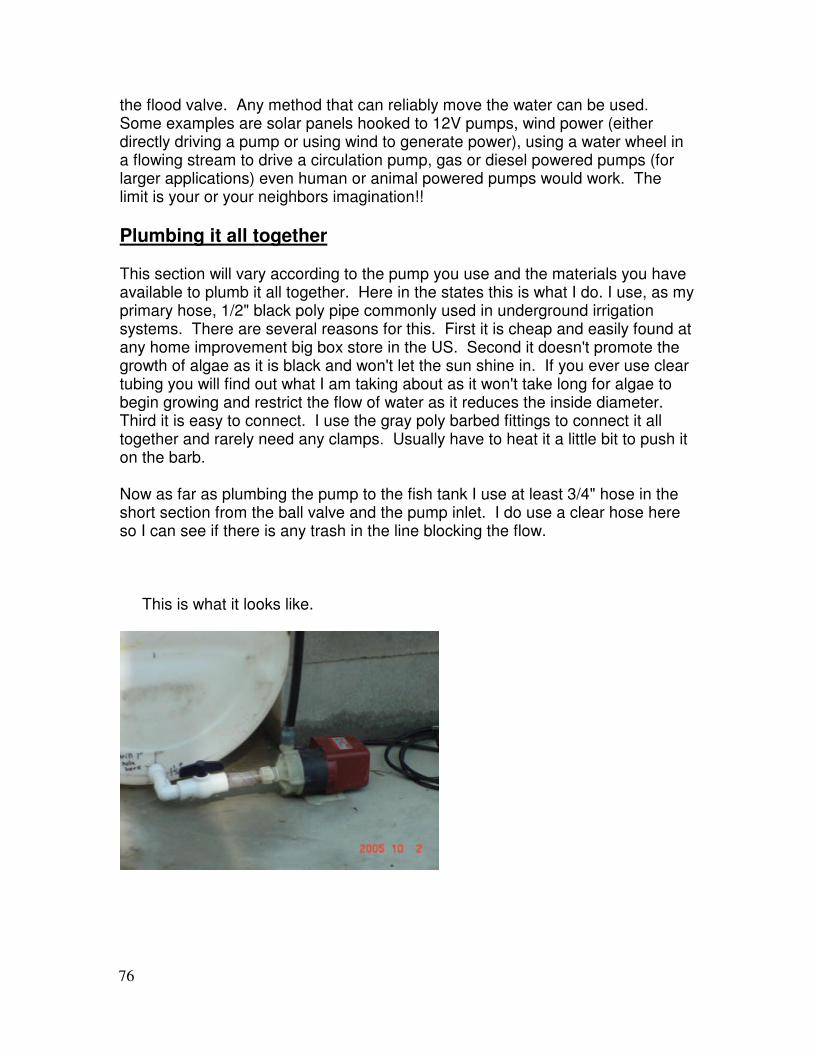
Plumbing it all together This section will vary according to the pump you use and the materials you have available to plumb it all together. Here in the states this is what I do. I use, as my primary hose, 1/2" black poly pipe commonly used in underground irrigation systems. There are several reasons for this. First it is cheap and easily found at any home improvement big box store in the US. Second it doesn't promote the growth of algae as it is black and won't let the sun shine in. If you ever use clear tubing you will find out what I am taking about as it won't take long for algae to begin growing and restrict the flow of water as it reduces the inside diameter. Third it is easy to connect. I use the gray poly barbed fittings to connect it all together and rarely need any clamps. Usually have to heat it a little bit to push it on the barb. Now as far as plumbing the pump to the fish tank I use at least 3/4" hose in the short section from the ball valve and the pump inlet. I do use a clear hose here so I can see if there is any trash in the line blocking the flow. This is what it looks like.
77
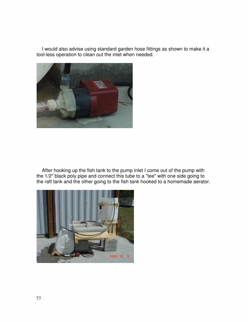
I would also advise using standard garden hose fittings as shown to make it a tool-less operation to clean out the inlet when needed.
After hooking up the fish tank to the pump inlet I come out of the pump with the 1/2" black poly pipe and connect this tube to a "tee" with one side going to the raft tank and the other going to the fish tank hooked to a homemade aerator.
78
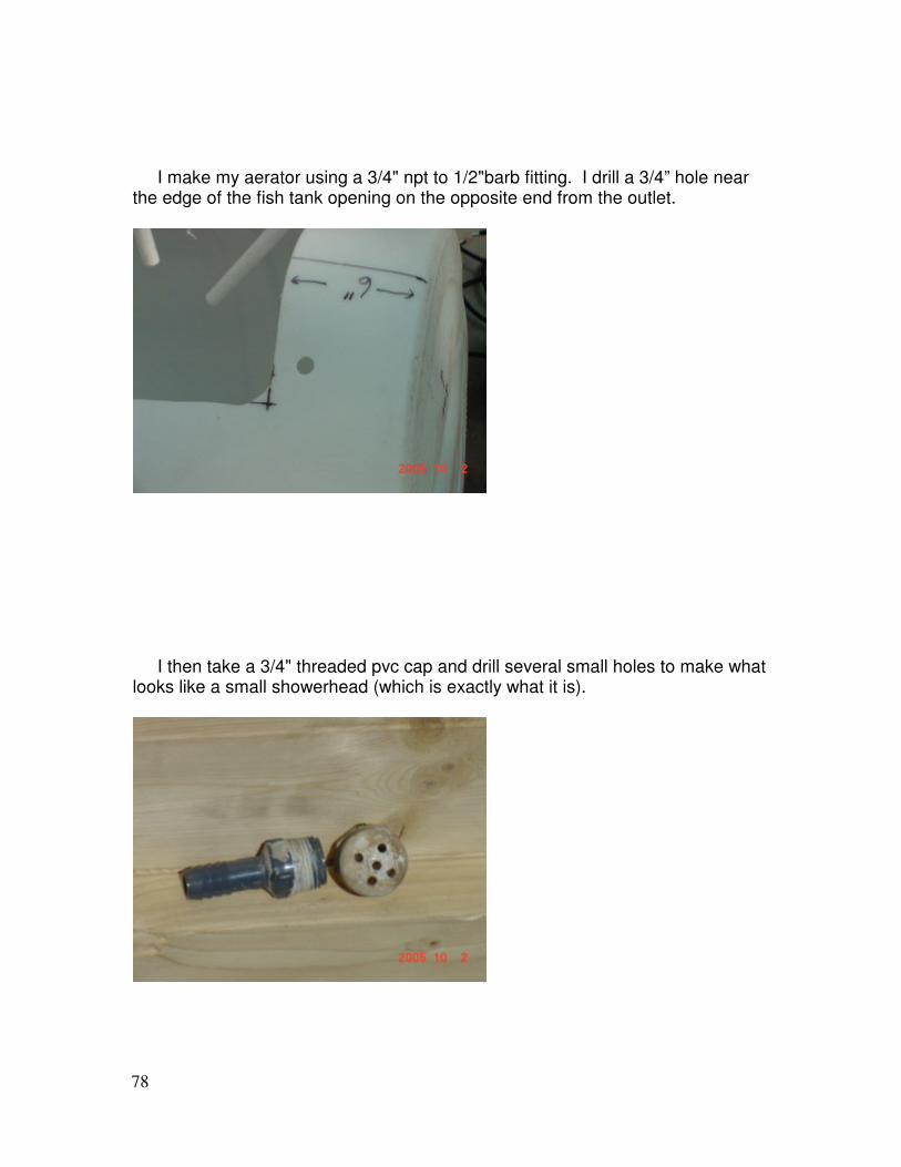
I make my aerator using a 3/4" npt to 1/2"barb fitting. I drill a 3/4” hole near the edge of the fish tank opening on the opposite end from the outlet.
I then take a 3/4" threaded pvc cap and drill several small holes to make what looks like a small showerhead (which is exactly what it is).

79
Fit the barb through from the inside with the barb sticking through to the outside. Slip the black poly tubing on here to capture the fitting in the edge of the fish tank (sometimes I have to warm up the tubing to make it easier to install).
The excess water is automatically diverted back to the fish tank and aerated to improve the overall health of the system. This works quite well when if for some reason (blockage or pump wear) the water doesn't get to the raft tank it will still allow for some aeration to the fish tank.
80
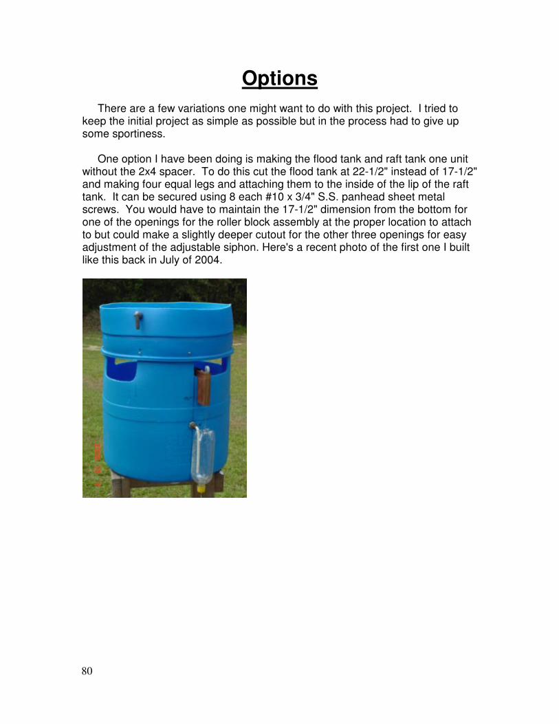
Options There are a few variations one might want to do with this project. I tried to keep the initial project as simple as possible but in the process had to give up some sportiness. One option I have been doing is making the flood tank and raft tank one unit without the 2x4 spacer. To do this cut the flood tank at 22-1/2" instead of 17-1/2" and making four equal legs and attaching them to the inside of the lip of the raft tank. It can be secured using 8 each #10 x 3/4" S.S. panhead sheet metal screws. You would have to maintain the 17-1/2" dimension from the bottom for one of the openings for the roller block assembly at the proper location to attach to but could make a slightly deeper cutout for the other three openings for easy adjustment of the adjustable siphon. Here's a recent photo of the first one I built like this back in July of 2004.
81
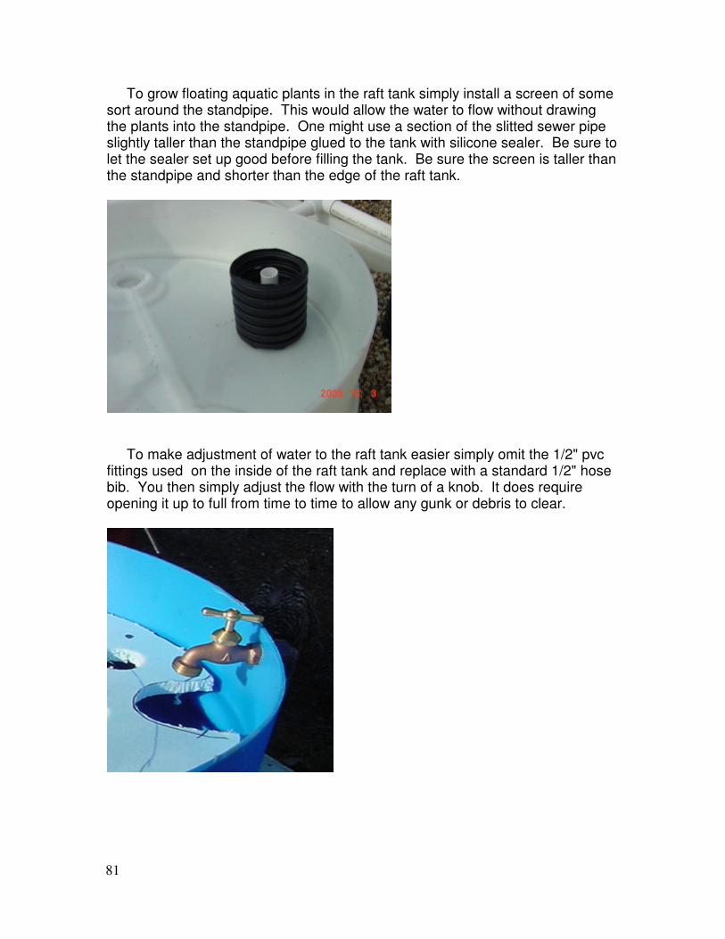
To grow floating aquatic plants in the raft tank simply install a screen of some sort around the standpipe. This would allow the water to flow without drawing the plants into the standpipe. One might use a section of the slitted sewer pipe slightly taller than the standpipe glued to the tank with silicone sealer. Be sure to let the sealer set up good before filling the tank. Be sure the screen is taller than the standpipe and shorter than the edge of the raft tank.
To make adjustment of water to the raft tank easier simply omit the 1/2" pvc fittings used on the inside of the raft tank and replace with a standard 1/2" hose bib. You then simply adjust the flow with the turn of a knob. It does require opening it up to full from time to time to allow any gunk or debris to clear.
82
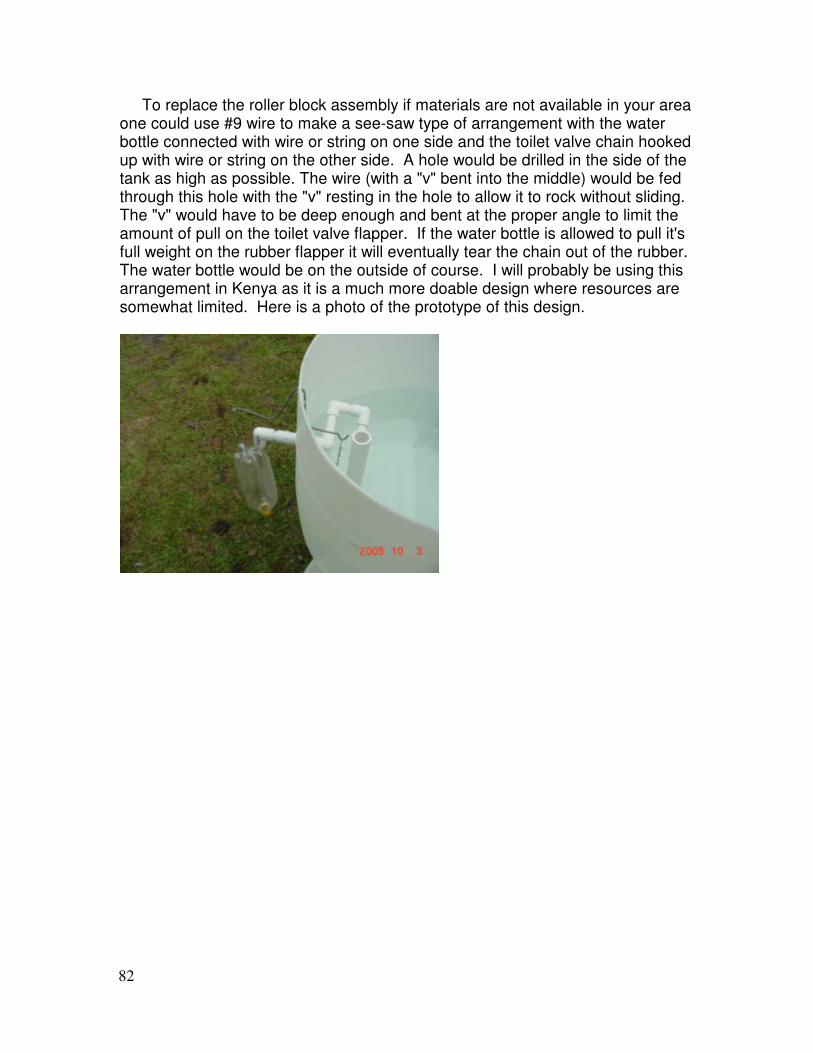
To replace the roller block assembly if materials are not available in your area one could use #9 wire to make a see-saw type of arrangement with the water bottle connected with wire or string on one side and the toilet valve chain hooked up with wire or string on the other side. A hole would be drilled in the side of the tank as high as possible. The wire (with a "v" bent into the middle) would be fed through this hole with the "v" resting in the hole to allow it to rock without sliding. The "v" would have to be deep enough and bent at the proper angle to limit the amount of pull on the toilet valve flapper. If the water bottle is allowed to pull it's full weight on the rubber flapper it will eventually tear the chain out of the rubber. The water bottle would be on the outside of course. I will probably be using this arrangement in Kenya as it is a much more doable design where resources are somewhat limited. Here is a photo of the prototype of this design.
83
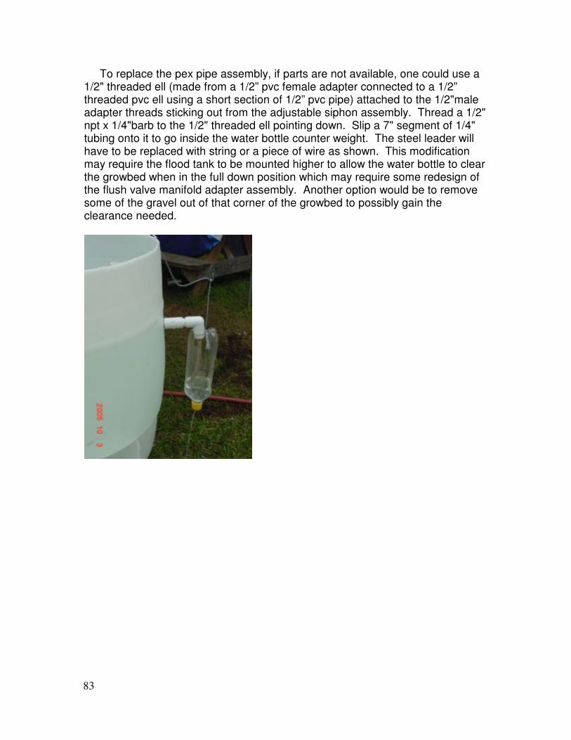
To replace the pex pipe assembly, if parts are not available, one could use a 1/2" threaded ell (made from a 1/2” pvc female adapter connected to a 1/2” threaded pvc ell using a short section of 1/2” pvc pipe) attached to the 1/2"male adapter threads sticking out from the adjustable siphon assembly. Thread a 1/2" npt x 1/4"barb to the 1/2" threaded ell pointing down. Slip a 7" segment of 1/4" tubing onto it to go inside the water bottle counter weight. The steel leader will have to be replaced with string or a piece of wire as shown. This modification may require the flood tank to be mounted higher to allow the water bottle to clear the growbed when in the full down position which may require some redesign of the flush valve manifold adapter assembly. Another option would be to remove some of the gravel out of that corner of the growbed to possibly gain the clearance needed.
84
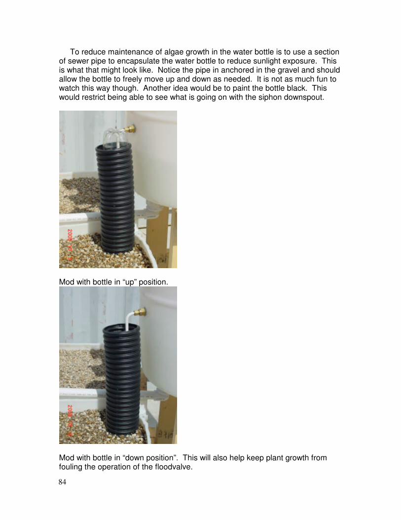
To reduce maintenance of algae growth in the water bottle is to use a section of sewer pipe to encapsulate the water bottle to reduce sunlight exposure. This is what that might look like. Notice the pipe in anchored in the gravel and should allow the bottle to freely move up and down as needed. It is not as much fun to watch this way though. Another idea would be to paint the bottle black. This would restrict being able to see what is going on with the siphon downspout.
Mod with bottle in “up” position.
Mod with bottle in “down position”. This will also help keep plant growth from fouling the operation of the floodvalve.
85
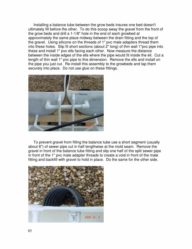
Installing a balance tube between the grow beds insures one bed doesn't ultimately fill before the other. To do this scoop away the gravel from the front of the grow beds and drill a 1-1/8" hole in the end of each growbed at approximately the same place midway between the drain fitting and the top of the gravel. Using silicone on the threads of 1" pvc male adapters thread them into these holes. Slip fit short sections (about 2" long) of thin wall 1"pvc pipe into these and install 1" pvc ells facing each other. Now measure the distance between the inside edges of the ells where the pipe would fit inside the ell. Cut a length of thin wall 1" pvc pipe to this dimension. Remove the ells and install on the pipe you just cut. Re-install this assembly to the growbeds and tap them securely into place. Do not use glue on these fittings.
To prevent gravel from filling the balance tube use a short segment (usually about 6") of sewer pipe cut in half lengthwise at the mold seam. Remove the gravel in front of the balance tube fitting and slip one half of the split sewer pipe in front of the 1" pvc male adapter threads to create a void in front of the male fitting and backfill with gravel to hold in place. Do the same for the other side.

86
Some sort of shock absorber arrangement on the steel leader to reduce the shock on the water bottle during the pull to open flapper would be a good idea. This could be a short spring installed between the water bottle and leader connection. One would have to be careful to make sure it is not so long to allow the siphon downspout to clear the water bottle entirely. Another option would be to shorten the pex pipe section on the steel leader attached to the toilet valve chain and install some soft rubber disks in place. One might even do a sandwich disk arrangement here using alternating rubber and some material like scotch brite pad pieces. Anything that would be waterproof and springy to absorb the shock on the line. There are many other "options" possible I'm sure. As they say "Necessity is the Mother of Invention". If you come up with some new ideas let me know. I'd love to hear about them. Please e-mail me at: [email protected]
87
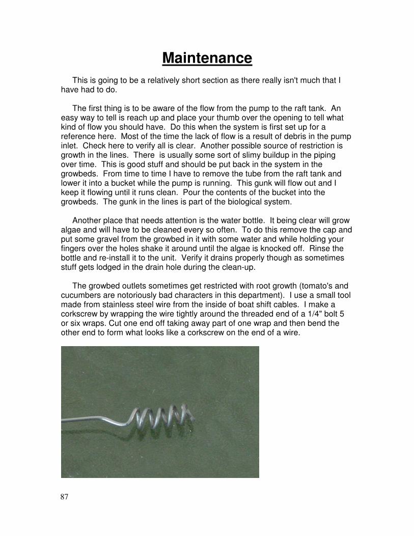
Maintenance This is going to be a relatively short section as there really isn't much that I have had to do. The first thing is to be aware of the flow from the pump to the raft tank. An easy way to tell is reach up and place your thumb over the opening to tell what kind of flow you should have. Do this when the system is first set up for a reference here. Most of the time the lack of flow is a result of debris in the pump inlet. Check here to verify all is clear. Another possible source of restriction is growth in the lines. There is usually some sort of slimy buildup in the piping over time. This is good stuff and should be put back in the system in the growbeds. From time to time I have to remove the tube from the raft tank and lower it into a bucket while the pump is running. This gunk will flow out and I keep it flowing until it runs clean. Pour the contents of the bucket into the growbeds. The gunk in the lines is part of the biological system. Another place that needs attention is the water bottle. It being clear will grow algae and will have to be cleaned every so often. To do this remove the cap and put some gravel from the growbed in it with some water and while holding your fingers over the holes shake it around until the algae is knocked off. Rinse the bottle and re-install it to the unit. Verify it drains properly though as sometimes stuff gets lodged in the drain hole during the clean-up. The growbed outlets sometimes get restricted with root growth (tomato's and cucumbers are notoriously bad characters in this department). I use a small tool made from stainless steel wire from the inside of boat shift cables. I make a corkscrew by wrapping the wire tightly around the threaded end of a 1/4" bolt 5 or six wraps. Cut one end off taking away part of one wrap and then bend the other end to form what looks like a corkscrew on the end of a wire.
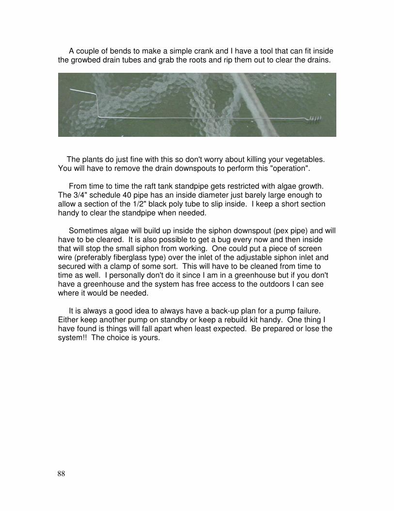
88
A couple of bends to make a simple crank and I have a tool that can fit inside the growbed drain tubes and grab the roots and rip them out to clear the drains.
The plants do just fine with this so don't worry about killing your vegetables. You will have to remove the drain downspouts to perform this "operation". From time to time the raft tank standpipe gets restricted with algae growth. The 3/4" schedule 40 pipe has an inside diameter just barely large enough to allow a section of the 1/2" black poly tube to slip inside. I keep a short section handy to clear the standpipe when needed. Sometimes algae will build up inside the siphon downspout (pex pipe) and will have to be cleared. It is also possible to get a bug every now and then inside that will stop the small siphon from working. One could put a piece of screen wire (preferably fiberglass type) over the inlet of the adjustable siphon inlet and secured with a clamp of some sort. This will have to be cleaned from time to time as well. I personally don't do it since I am in a greenhouse but if you don't have a greenhouse and the system has free access to the outdoors I can see where it would be needed. It is always a good idea to always have a back-up plan for a pump failure. Either keep another pump on standby or keep a rebuild kit handy. One thing I have found is things will fall apart when least expected. Be prepared or lose the system!! The choice is yours.
89
Starting the System Fill the fish tank to the top with water and start the pump. You would want to add some food grade Hydrogen Peroxide or I have heard of some using bleach to disinfect the system. The idea is to get as sterile an environment to start off with. Don’t want to start the system with any diseases right off the start. Water should fill the top tank and flow through the standpipe to the flood tank. Set the top of the siphon to the max height and wait for the system to actuate the flush valve. Look at the growbeds and adjust the level of the manifold to fill the growbeds equally. This may take a few cycles. Also, look at the volume of water dumped per cycle. If it is too much lower the top of the siphon until the volume stops at just below the top of the surface of the gravel. If the siphon fills the counterweight for too long this too can be adjusted by raising the bottom of the internal siphon tube being careful to not change the top setting. Let the system run a couple of days to allow the Hydrogen Peroxide or Chlorine to gas out of the water. Once the system is up and running consistently for a couple days check and adjust the pH. Adjusting the pH using un-iodized salt (preferably sea salt) to raise it and vinegar to bring it down. Add a small amount of healthy pond or lake water or biofilter starter and some fish. I would suggest cheap feeder goldfish to begin with as there is a strong likelihood some will die while the system stabilizes. This is not the time to use some of your neighbors high dollar Koi to help out your project!! Now would be a good time to plant some easy growing seeds in the gravel beds. Beans are a good choice for starters as the sprout quickly and will begin taking up nutrients. As far as checking the system with a water test kit goes you will see the following happen: First the ammonia will run up quite high. This is normal as the fish will be producing it and the nitrifying bacteria haven't built up yet. If you start losing fish at this stage simply remove some of the water and add some well water if possible. If well water is not available it might be advisable to have some sterilized water on hand. Remember this handy rule “The solution to pollution is dilution” When the Nitrosomonas bacteria have built up to sufficient levels you will see the ammonia to go to zero very quickly. This stage is where I killed a good many fish. In my impatience I started loading up the fish at just the wrong time!! The second phase of nitrification has yet to get started. The nitrites will go very high now until the Nitrobacter reach sufficient levels to reduce the nitrites to almost

90
zero. This is a very critical time as the nitrites are very toxic to the fish. The nitrates will then rise and this is where the system is producing the nutrients for the plants to get healthy. This can take a few weeks to stabilize so don’t get impatient. Don't overfeed the fish and you are on your way to a very enjoyable hobby and a wonderful way to weed free gardening. Have a seat and just watch and enjoy your hard work!! Once your system is up and stabilized you will almost be able to watch the plants grow!!
91
Why I do What I Do
It was suggested I include a section in this manual to express my motivation and inspiration for what I do and my motivation to make this manual free of charge in this day of everything at a cost. To put it plainly I am an unabashed Christian. I was born again at an early age and have committed my life to serving Jesus Christ in any way He sees fit. Sometimes that has led to more conventional service such as church planting. For a period of over 20 years it was writing Contemporary Christian Music and performing it in any venue available from churches, to prisons, on the streets and coffeehouses and in juvenile delinquent centers, etc... I have even done concerts in high schools when that was still allowed. As of the past few years I have had a business repairing yachts and am now developing technologies to assist the more impoverished peoples of this world. There is a passage in Matthew 25:31-46 where the question was asked of Christ by the people entering into Heaven “When did we feed you, give you water, clothe you or take you in?”. He said “In as much as you did it unto the least of these my brothers, you did it unto me“. This is my focus. So much of our time nowadays is consumed with the process of getting more. I believe we must be consumed with the process of giving more. It is the example that Christ gave when He gave His life for us freely (John 3:16, Romans 5:8). He gave the gift of eternal life with no strings attached. He will take us just as we are. No prior purification or good works required. No cost involved other than what He paid for us with His life. This is why I cannot, in good conscience withhold, to a father or mother who is having a hard time feeding their children, information that may help unless they pay me something. I am by no means inferring that others are wrong to charge for such information. This is simply my personal conviction. I will however ask, if it is within your means to help us in this venture and make a donation to help it would be greatly appreciated. Donations can be made through PayPal.com. My e-mail address to use at the PayPal site is [email protected]. If it is outside your means, no problem. Please take this information and hopefully it will help you feed your children and please know God has heard you and your children’s prayers. This is just a small way He is letting you know.

92
A Little Bit Of What To Look Forward To
A few pictures of what I’ve grown in my large system as well as Barrel-ponics unit.
Picture of my greenhouse in March of 2005
Papaya’s anyone!!
93
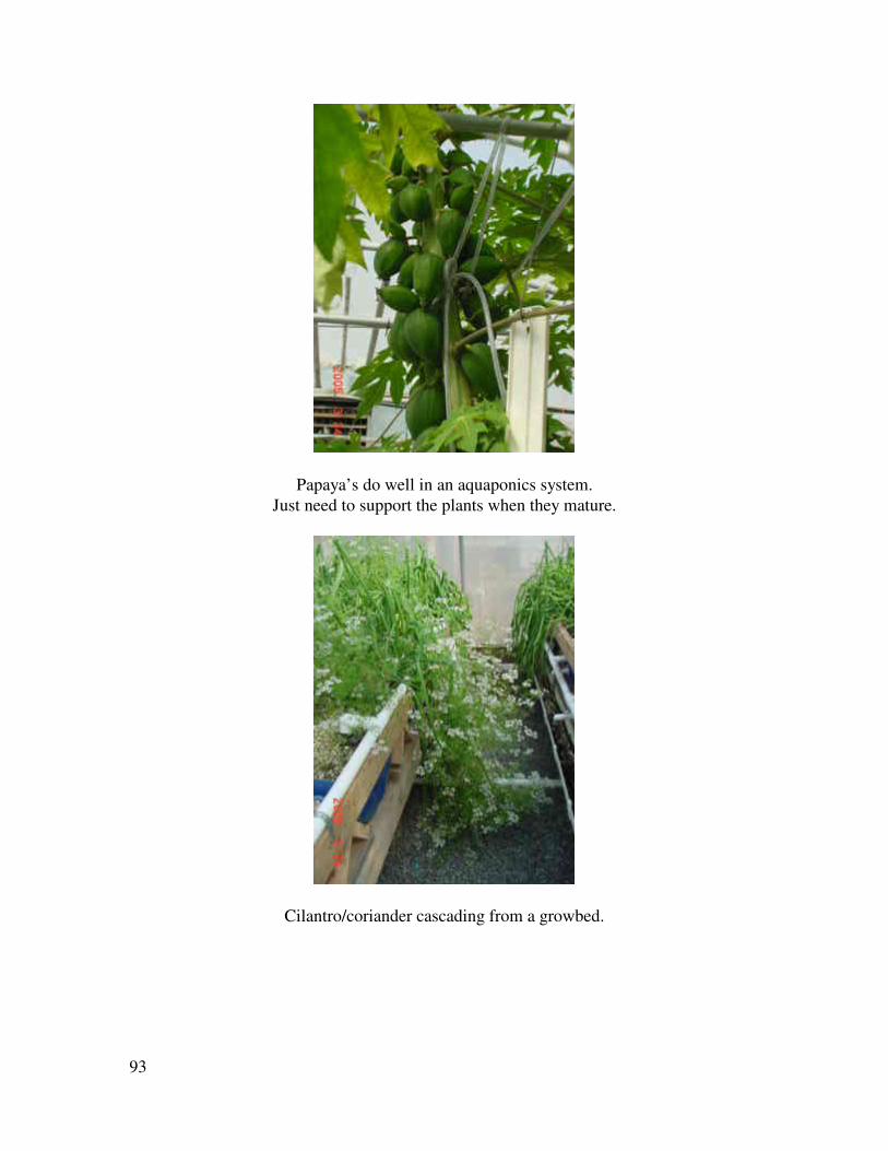
Papaya’s do well in an aquaponics system.
Just need to support the plants when they mature.
Cilantro/coriander cascading from a growbed.
94
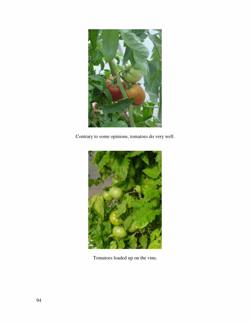
Contrary to some opinions, tomatoes do very well.
Tomatoes loaded up on the vine.
95
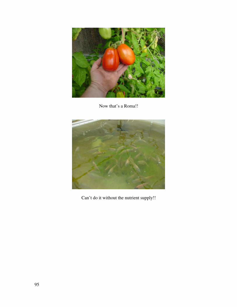
Now that’s a Roma!!
Can’t do it without the nutrient supply!!
96
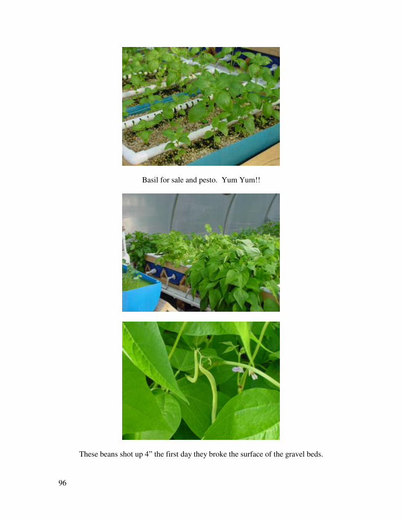
Basil for sale and pesto. Yum Yum!!
These beans shot up 4” the first day they broke the surface of the gravel beds.
97
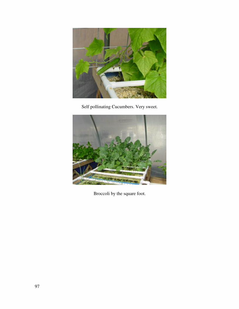
Self pollinating Cucumbers. Very sweet.
Broccoli by the square foot.
98
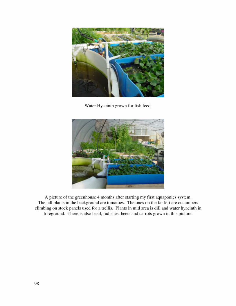
Water Hyacinth grown for fish feed.
A picture of the greenhouse 4 months after starting my first aquaponics system.
The tall plants in the background are tomatoes. The ones on the far left are cucumbers
climbing on stock panels used for a trellis. Plants in mid area is dill and water hyacinth in
foreground. There is also basil, radishes, beets and carrots grown in this picture.
99
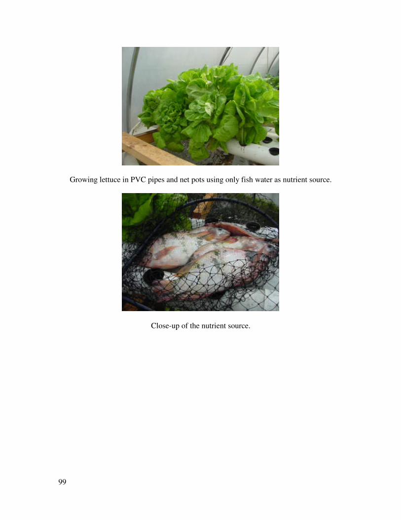
Growing lettuce in PVC pipes and net pots using only fish water as nutrient source.
Close-up of the nutrient source.
100
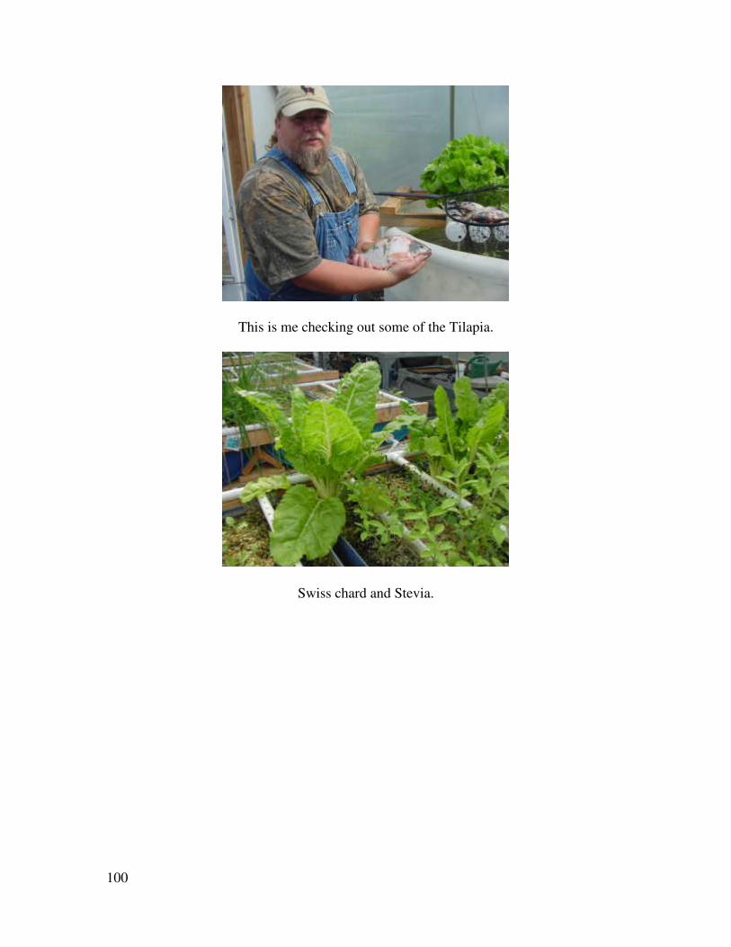
This is me checking out some of the Tilapia.
Swiss chard and Stevia.
101
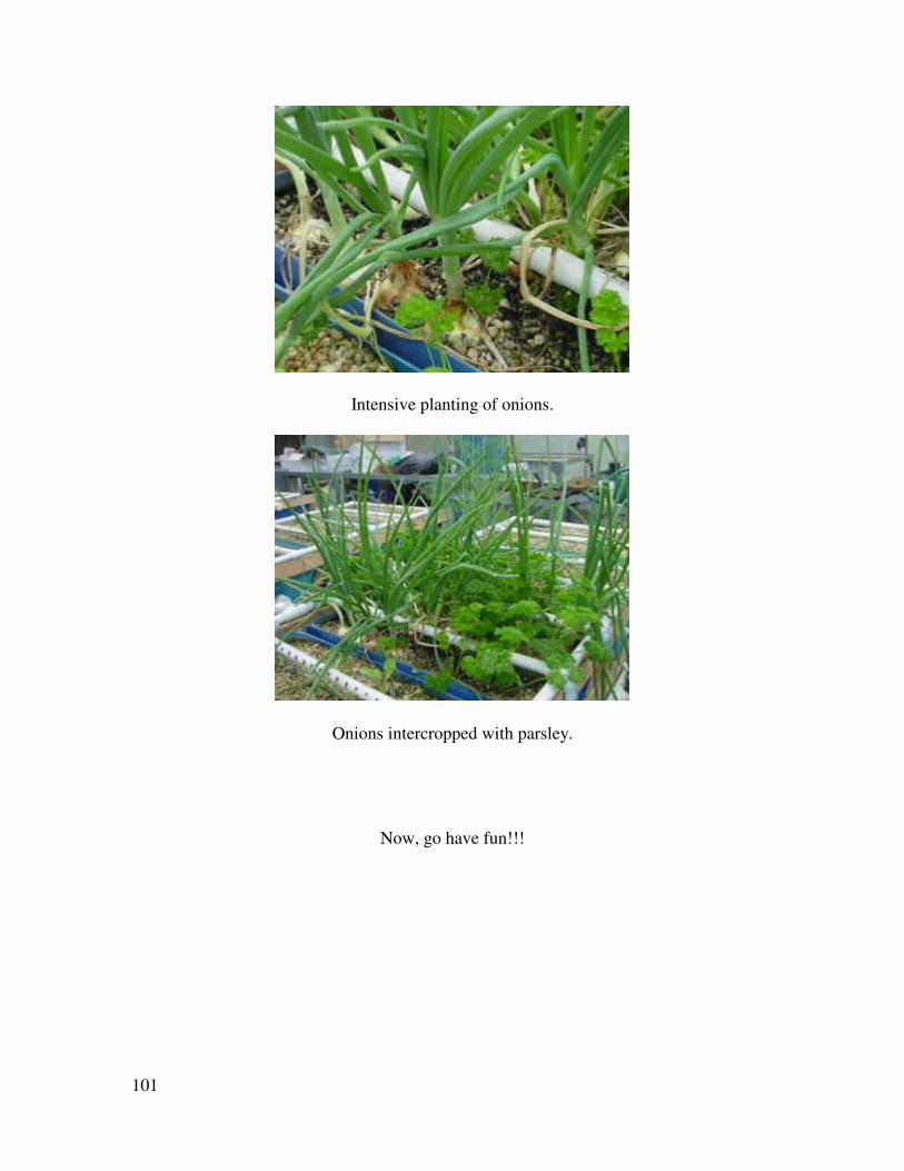
Intensive planting of onions.
Onions intercropped with parsley.
Now, go have fun!!!