baseline configuration - highlights barry barish ilcsc 9-feb-06
Post on 20-Dec-2015
219 views
TRANSCRIPT

Baseline Configuration - Highlights
Barry BarishILCSC9-Feb-06
9-Feb-06 ILCSC 2
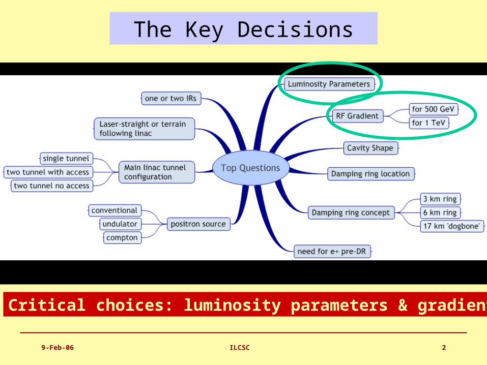
The Key Decisions
Critical choices: luminosity parameters & gradient

9-Feb-06 ILCSC 3
Making Choices – The Tradeoffs
Many decisions are interrelated and require input from several WG/GG groups

9-Feb-06 ILCSC 4
The Baseline Machine (500GeV)
not to scale
~30 km
e+ undulator @ 150 GeV (~1.2km)x2R = 955m
E = 5 GeV
RTML ~1.6km
ML ~10km (G = 31.5MV/m)20mr
2mrBDS 5km

9-Feb-06 ILCSC 5
Parametric Approach
• A working space - optimize machine for cost/performance

9-Feb-06 ILCSC 6
Electron Source
Positron-style room-temperature
accelerating section
diagnostics section
standard ILC SCRF modules
sub-harmonic bunchers + solenoids
laser E=70-100 MeV
• DC Guns incorporating photocathode illuminated by a Ti: Sapphire drive laser.
• Long electron microbunches (~2 ns) are bunched in a bunching section
• Accelerated in a room temperature linac to about 100 MeV and SRF linac to 5 GeV.
DC gun(s)
9-Feb-06 ILCSC 7
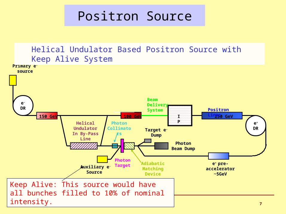
Positron Source
Primary e-
source
e-
DR
Target e- Dump
Photon Beam Dump
e+
DR
Auxiliary e- Source
Photon Collimators
Adiabatic Matching
Device
e+ pre-accelerator
~5GeV
150 GeV 100 GeV
HelicalUndulatorIn By-Pass
Line
PhotonTarget
250 GeV
Positron Linac
IP
Beam Delivery System
Keep Alive: This source would have all bunches filled to 10% of nominal intensity.
Helical Undulator Based Positron Source with Keep Alive System

9-Feb-06 ILCSC 8
ILC Small Damping Ring
Multi-Bunch Trains with inter-train gaps

9-Feb-06 ILCSC 9
ILC Damping Ring: Baseline Design
• Positrons: – Two rings of ~6 km circumference in a single tunnel.
– Two rings are needed to reduce e-cloud effects unless significant progress can be made with mitigation techniques.
– Preferred to 17 km dogbone due to:
•Space-charge effects •Acceptance •Tunnel layout (commissioning time, stray fields)
• Electrons:
– One 6 km ring.

9-Feb-06 ILCSC 10
Main Linac: SRF Cavity Gradient
Cavity type
Qualifiedgradient
Operational gradient
Length* energy
MV/m MV/m Km GeV
initial TESLA 35 31.5 10.6 250
upgrade LL 40 36.0 +9.3 500
* assuming 75% fill factorTotal length of one 500 GeV linac 20km
9-Feb-06 ILCSC 11
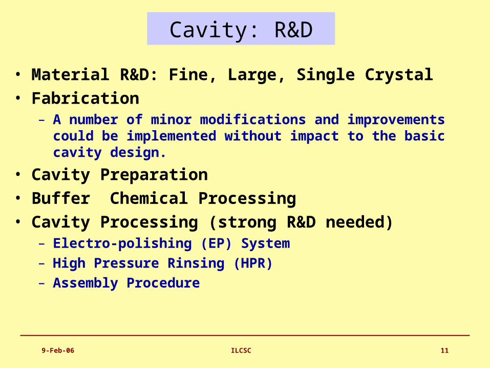
Cavity: R&D
• Material R&D: Fine, Large, Single Crystal• Fabrication
– A number of minor modifications and improvements could be implemented without impact to the basic cavity design.
• Cavity Preparation • Buffer Chemical Processing• Cavity Processing (strong R&D needed)
– Electro-polishing (EP) System– High Pressure Rinsing (HPR)– Assembly Procedure

9-Feb-06 ILCSC 12
Superconducting RF Cavities
High Gradient Accelerator35 MV/meter -- 40 km linear collider

9-Feb-06 ILCSC 13
Improved ProcessingElectropolishing
Chemical Polish
Electro Polish

9-Feb-06 ILCSC 14
RF Power: Modulator
BaselineAlternate
The Bouncer Compensated Pulse Transformer Style Modulator
Operation: an array of capacitors is charged in parallel, discharged in series. (~2m)
Will test full prototype in 2006

9-Feb-06 ILCSC 15
RF Power: Baseline Klystrons
Thales CPI Toshiba
Specification:
10MW MBK
1.5ms pulse
65% efficiency

9-Feb-06 ILCSC 16
Increasediameter beyond X-FEL
Increasediameter beyond X-FEL
Review 2-phase pipe size and effect of slope
ILC Cryomodule

9-Feb-06 ILCSC 17
ILC Beam Delivery System
• Baseline (supported, at the moment, by GDE exec)– two BDSs, 20/2mrad, 2 detectors, 2 longitudinally separated IR halls
• Alternative 1– two BDSs, 20/2mrad, 2 detectors in single IR hall @ Z=0
• Alternative 2– single IR/BDS, collider hall long enough for two push-pull detectors

9-Feb-06 ILCSC 18
Conclusions -- BCD
• The baseline configuration for the ILC has been established and is document in the BCD (a 700+ page electronic document)
• We have put the BCD under configuration control and are evolving it now in a controlled manner
• The BCD also defines alternatives and the combination of the baseline and alternative will give good guidance for the ILC R&D program
• The BCD is now being used as the starting point and basis for the reference design / cost effort this year.