basic course - manual library — roland dg
TRANSCRIPT

Basic Course
All rights reserved.


1
Contents
Contents
ContentsChapter1 Outline ............................................................................................................................................................ 3
Basic concept of SRP Player Pro ............................................................................................................. 4
Types of model data................................................................................................................................... 5
Terminology of SRP Player Pro ............................................................................................................... 7
Description of the names related to modeling machine and SRP Player Pro data ............. 8
Description of CL (milling data) created by SRP Player Pro ......................................................... 9
Chapter2 Basic Operation .........................................................................................................................................11
Starting & ending of SRP Player Pro ...................................................................................................12
Screen and names of SRP Player Pro ..................................................................................................13
How to use a mouse on SRP Player Pro ............................................................................................14
Flow of data preparation by SRP Player Pro ....................................................................................15
Preferences ..................................................................................................................................................16
Preparation of new SRP Player Pro data ...........................................................................................17
Layer function ............................................................................................................................................20
Preparation of new workpiece .............................................................................................................21
Preparation of a project ..........................................................................................................................24
CL generation .............................................................................................................................................35
CL Data Show Control .............................................................................................................................38
Chapter3 Profi le Description ....................................................................................................................................39
Types of profi le ..........................................................................................................................................40
Profi le Menu ...............................................................................................................................................41
Roughing (Z-level) ....................................................................................................................................42
Finishing (Z-level) .....................................................................................................................................58
Finishing (Scanning-line) .......................................................................................................................72
Edge Cutting ...............................................................................................................................................78
Curve Cutting .............................................................................................................................................82

2
Contents
Contents
Chapter4 Profi le Initial Values ........................................................................................................................................87
About profi le initial values ..........................................................................................................................88
Roughing (Z-level) ..........................................................................................................................................90
Finishing (Z-level) ...........................................................................................................................................96
Finishing (Scanning-line) .............................................................................................................................99
Edge Cutting .................................................................................................................................................. 102
Curve Cutting ................................................................................................................................................ 106
Chapter5 Common Items ............................................................................................................................................. 109
Description of other operations ............................................................................................................. 110
Wall Property ................................................................................................................................................. 114
Support Library ............................................................................................................................................ 115
Edit Project ..................................................................................................................................................... 118
Cut Off Area ................................................................................................................................................... 121
Change Tool ................................................................................................................................................... 129
Project Template .......................................................................................................................................... 134
Virtial Parting Plane ..................................................................................................................................... 141
Chapter6 Optimization ................................................................................................................................................. 143
Optimizing CL Data ..................................................................................................................................... 144
Elimination of Air Cut /Optimize Auto Clearance ............................................................................. 145
Chapter7 Edit Registered Data ................................................................................................................................... 147
Registration and Edit .................................................................................................................................. 148
Tool Type ......................................................................................................................................................... 149
Tools .................................................................................................................................................................. 150
Material/Milling Conditions ..................................................................................................................... 152
Workpiece Size .............................................................................................................................................. 153
To input a combination of material and tool according to cut conditions information .... 154

Outline

4
Chapter 1
Outline
Basic Operation
Profi le Description
Profi le Initial ValuesCom
mon Item
sO
ptimization
Edit Registered Data
SRP Player Pro basic training text
Outline
Types of fi les Version & File Format Elements possible to be retrievedCraft MILL fi le Craft MILL Plus R AllIGES fi le
(Inutial Graphics Exchange Specifi cation)
IGESV5.1 * In compliance with JAMA-IS
All images output with NURBS (Type 128)
Curved surface and curved line
Rhino fi le Rhino 1.0 / 1.1 / 2.0 / 3.0/ 4.0 Curved surface, curved line and polygon
meshSTL fi le
(Stereolithography Interface Format)
Both of Binary and ASCII formats can be
retrieved.
Triangle polygon conglomerate
DXF fi le 3D polygon data of DXF fi le 3D polygon data of DXF fi le
Basic concept of SRP Player Pro
What is SRP Player Pro?
It is a 3 dimensional CAM module, by which a cutter path having high quality can be created without diffi culty, by making use
of many 3D modeler data including Rhinoceros and others.
Making use of 3D modeler data
You cannot make any graphic using SRP Player Pro. You should retrieve (import) those graphics created by other applications
software and add milling conditions to them to output the milling data.
Types of fi les SRP Player Pro available on

5
Chapter 1 SRP Player Pro basic training text
Outline
Outline
Basic Operation
Profi le Description
Optim
izationProfi le Initial Values
Comm
on Items
Edit Registered Data
Types of model data
Diff erence of the fi nish by subject model data
Depending on the type of data being output from CAD/CG, the fi nish after cutting process varies.
The diff erence of the fi nish by data is described below.
Curved surface is able to describe the details in an accurate and smooth fashion
SRP Player Pro, which creates a path by directly using the curved surface
The reproducibility of curved surface is extremely excellent and a smooth fi nish can be secured.
*Because most of 3DCAM software once converts fi rst the read curved surface into polygon. Therefore even the surface data
has been read, it is processed as polygon data at the stage of internal milling. The fi nish becomes the level equivalent to the
state polygon data has been cut.
Polygon data, which describes the graphic by polygon mesh (polyhedron approximate), performs
smooth shading in the display milling and describes it in visually a smooth fashion
Although the calculation is performed very quick, tolerance against curved line occurs.
The accuracy in fi nish is just the same as the accuracy of polygon fi nish.
(If you use the “Polygon smoothing function” installed on SRP Player Pro, you can approximate the rough polygon fi nish to
curved surface data also, because smoothing milling is performed to the polygon to create a path.)
Diff erence between curved surface data and polygon data
To approximate the surface to polygon
To offset the cross section by the radius of tools
To off set the surface Finish is shown a polygon with status.
Polygon calculation method
To off set the surface Parallel use of balls (virtual tools) layout and process by contact method
Creation of a smooth path that passes through the center of a ball (virtual tool)
The finish reproduces a surface.
SRP Player Pro

6
Outline
Chapter 1
Basic Operation
Profi le Description
Optim
izationProfi le Initial Values
Comm
on Items
Edit Registered Data
Large volume polygon data, which is created by describing in details the smooth and actual shape,
created with point group measuring device such as 3D scanner, etc
Smooth curved surface shape has been shown with a polygon mesh keeping its high accuracy. Therefore, high accuracy can
be secured in the fi nish, but it becomes extremely huge size. CAM software used in general may be able unavailable.
SRP Player Pro has been developed and improved in order to process large volume polygon model as well.
Following diff erence is shown as a result of milling by SRP Player Pro.
Selecting the data output method far diff erent purposes by capturing each performance is also an important process.
Above figure is a screen in which STL of 650,000 polygon and jigs
required for milling were built with a surface and read. SRP Player Pro
can process both a curved surface and a polygon together.
Curved surface data Polygon data
SRP Player Pro (Data preparation and milling)
Polygon smoothing
Computing time required by PC
Accuracy of fi nish after milling
Long Short
High Low

7
Chapter 1 SRP Player Pro basic training text
Outline
Outline
Basic Operation
Profi le Description
Optim
izationProfi le Initial Values
Comm
on Items
Edit Registered Data
Terminology of SRP Player Pro
Description of the words and terms used for SRP Player Pro
Workpiece:
Means in general the materials to be processed
Size and location are defi ned for the workpiece by SRP Player Pro.
A project is created by organizing the milling methods of this workpiece together and milling data is created.
Project:
The direction to process a workpiece is determined and the process to be processed is controlled.
Profi le:
A milling process, which is collectively kept under control in a project.
Current:
The workpiece, project and profi le currently being created are respectively called as a current workpiece, current project
and current profi le.
Contour:
Means a silhouette line at a certain height of a model being processedIn SRP Player Pro, a certain part of CL height is called
as a contour also.
Model Coordinate system:
Means a coordinate system of model data created by a curved surface or a polygon,also called as a world coordinate
system.
Project Coordinate system :
A coordinate system based on the milling orientation and origin against the defi ned workpiece. This origin becomes as a milling origin.
Allowance:
Means an excess material thickness to be left unprocessed for the fi nal milling shape
Except for curve cutting, CL is generated in such a manner that even thickness can be secured in material direction to the
milling shape.
In case of curve cutting, the thickness is adjusted in the height direction only.
NC:
An abbreviation of Numerical Control. This means the data that controls milling machines. This format is called as G-code.
CL:
An abbreviation of Cutter Location. This means the track of the toll movement. One (1) CL is generated from one (1) profi le.
CL data:
Means the data to be output to milling machine for which CL has been formatted according to that milling machine
Tool Initial Position:
Means the position of a tool when milling should start
X-Y coordinate values at the tool original position by SRP Player Pro are located based on the project origin. Only the Z coordinate values are located at
the height determined based on the workpiece upper face as a reference surface.
Clearance height:
When generating CL, the tool position is moved up to a height to prevent the tool from interfering with the item being processed when that tool moves
from a certain cutting section to the next cutting section. The height in this case is called as a clearance height.
The clearance height by SRP Player Pro is the height determined based on the workpiece upper face as a reference surface.

8
Chapter 1
Outline
Basic Operation
Profi le Description
Profi le Initial ValuesCom
mon Item
sO
ptimization
Edit Registered Data
SRP Player Pro basic training text
Outline
Description of the names related to modeling machine and
SRP Player Pro data
Collation of the names related to modeling machine and data
Relationship between the names related to modeling machine and data
Modeling machine
On SRP Player Pro data
Workpiece (material)
Back up board
Workpiece(material):
Means the material used to cutout a modelMilling data is created to cutout a model from a square block.It is important to match the size of actual material with the size of a workpiece on the data.
X-Y-Z origin & project origin:The origins (XO/YO/ZO) which should become the reference positions for milling by a modeling machine are matched with the process origin on the data (project origin).
Back up board :
If you put a workpiece material directly on the moving table of a modeling machine, such troubles would occur that the table must be cut when milling the portion below the workpiece is required or the parallel cannot be secured, etc.In order to prevent this, affix a material having a role as a back up board on the table and secure the facing, by which the parallel accuracy is secured and permits milling below the workpiece.SRP Player Pro has a function to display back up board on its data. Therefore, you can create the data, simulating actual milling situation.
X/Y/Z origins
Back-up board
Project origin
Work (material)

9
Chapter 1 SRP Player Pro basic training text
Outline
Outline
Basic Operation
Profi le Description
Optim
izationProfi le Initial Values
Comm
on Items
Edit Registered Data
Tool
Approaching section
Cutting section
Model to be milled
Cutting initial position
Escaping section
Description of CL (milling data) created by SRP Player Pro
What is a CL?
An abbreviation of Cutter Location. This means the track of the tool movement . One (1) CL is generated from one (1) profi le.
The CL of SRP Player Pro starts from the tool initial position and repeats the milling in the order of approaching, cutting and
escaping and fi nally returns to the tool initial position.
In the CL display, the track of the tool movement is displayed. Quick feed section is indicated by dotted lines whereas the
cutting section by solid lines.

10
Outline
Chapter 1
Basic Operation
Profi le Description
Optim
izationProfi le Initial Values
Comm
on Items
Edit Registered Data

Basic Operation

12
Outline
Basic Operation
Profi le Description
Optim
ization
Chapter 2 SRP Player Pro basic training text
Basic Operation
Profi le Initial ValuesCom
mon Item
sEdit Registered D
ata
Starting & ending of SRP Player Pro
How to start
Following 4 methods are available for starting SRP Player Pro:
From Windows start menu, select Program > SRP Player Pro > SRP Player Pro1.0
How to end
Following 2 methods are available for ending SRP Player Pro.
Double click the icon
of SRP Player Pro.
Double click SPP fi le. Drag SPP fi le on
the icon.
From fi le menu of SRP Player Pro, select “Exit”
Click “X”(close) located at upper right of the SRP Player Pro screen.

13
Outline
Basic Operation
Profi le Description
Optim
ization
Chapter 2 SRP Player Pro basic training text
Basic Operation
Profi le Initial ValuesCom
mon Item
sEdit Registered D
ata
Screen and names of SRP Player Pro
Names of respective portion
Menu bar & tool bar:
Almost same commands are available on the menu bar and tool bar.
Project tool bar:
After preparing a new fi le, start the operation in the order from left icon. The icon is displayed in grey at the beginning. When
you are proceeding with the operation in the order from left icon, the display of icons becomes active and the operation
becomes possible.
Project edit dialog:
This dialog is automatically displayed when a project has been created.
Menu bar Project tool bar
Current tool bar
View port
View toolbar
Project edit dialog
Status bar
Scale
World Coordinate Axes

14
Outline
Basic Operation
Profi le Description
Optim
ization
Chapter 2 SRP Player Pro basic training text
Basic Operation
Profi le Initial ValuesCom
mon Item
sEdit Registered D
ata
How to use a mouse on SRP Player Pro
How to use a mouse
Using left button, you can operate following functions:
Execution of a command from menu bar or icon
ON or OFF of a command
Selection of a graphic
Selection of an object using a frame.( Only on case that A whole graphic is located inside the frame.)
* When you push the left button while holding down Ctrl, you can select a graphic even when only a part of that graphic
has been contained.
Using right button, you can operate following functions:
The command which starts by right button executes the items set on the icon.
If the view observing point is inclined while not in parallel to any X, Y or Z axis in the coordinate system, the view can be
rotated by dragging the mouse with a right button.
When the view observing point is in parallel to X, Y and Z axes in the coordinate system, pan can be performed by
dragging the mouse with a right button.
If you drag the mouse up or down with a right button while holding down Ctrl, you can execute expansion or shrinkage.
Using wheel button (center button), you can operate the following functions:
Dynamic zooming by rotating the wheel

15
Outline
Basic Operation
Profi le Description
Optim
ization
Chapter 2 SRP Player Pro basic training text
Basic Operation
Profi le Initial ValuesCom
mon Item
sEdit Registered D
ata
Flow of data preparation by SRP Player Pro
0. Before start working:
Check the setting of milling machine.
(If the milling machine is not properly set, milling data that will maximize the milling machine performance cannot be
created.)
1. New preparation:
Read the model data and create SRP Player Pro fi le.
In addition, create a work space folder (a folder to control the milling data).
[Note] Confi rm that the model fi le has been properly read.
2. Preparation of a new workpiece:
Determine the size and position of a workpiece (material to be cut).
3. Preparation of a project:
Determine the project name.
Select the material.
Select the milling direction and cut off range.
Select the type of cutting process.
Select the tool to be used for each process.
4. Execution of calculation:
Generate a CL.
5. Display of cut results:
Check the results through easy cut simulation.
Before outputting the milling data to milling machine, make sure to check the CL display (Show CL Data).
6. Data output:
Output the data to the milling machine.

16
Outline
Basic Operation
Profi le Description
Optim
ization
Chapter 2 SRP Player Pro basic training text
Basic Operation
Profi le Initial ValuesCom
mon Item
sEdit Registered D
ata
Preferences
Machine Settings
Click the item “Option” > “Preferences” in the menu bar.
Open the dialog “Machine Settings” in the “SRP Player Pro Preferences” and select the modeling machine name to be used.
Perform “Apply” and close the dialog to fi nish.

17
Outline
Basic Operation
Profi le Description
Optim
ization
Chapter 2 SRP Player Pro basic training text
Basic Operation
Profi le Initial ValuesCom
mon Item
sEdit Registered D
ata
Preparation of new SRP Player Pro data
Preparation of new SPP fi le
Read the 3D model fi le (polygon model or surface model) and create a SRP Player Pro fi le (*spp).
Screen confi guration of SRP Player Pro
Immediately after starting, the tool bar is displayed as above.
When preparing the data, milling processed with selecting the icons in the active display in the order from the left one.
New fi le
File > New [Ctrl + N]
When this command has been selected, a wizard for new preparation will be displayed.
When preparing a fi le, a work space folder having the same name as the fi le name is crerated.
Work space folder means a folder that control the milling data created by SRP Player Pro.
Work space folder SRP Player Pro fi le

18
Outline
Basic Operation
Profi le Description
Optim
ization
Chapter 2
Profi le Initial ValuesCom
mon Item
sEdit Registered D
ata
Designation of a model fi le
If you select “Next” after inputting the fi le name in the Model File fi eld, a model fi le designated wizard will be displayed.
If you push the Browse button, a window to “Open" will be opened. Here, select the file location and designate the file
according to the subject fi le type.
SRP Player Pro fi le being created newly, the preparation of a work space folder having the same name, fi le location and the
designated model fi le name will be displayed. If the displayed conditions are correct, push “Finish”. If not correct, push “Back”
to make change.

19
Outline
Basic Operation
Profi le Description
Optim
ization
Chapter 2
Profi le Initial ValuesCom
mon Item
sEdit Registered D
ata
shading
wire frame + shading
wire frame
If you select “Finish” after confi rming the conditions, the progress bar “Reading File now” will be displayed.
When the reading of a model fi le is complete, the model will be displayed with a wire frame.
Rotate or zoom up the read model fi le using a tool in the view tool bar to check for any missing surface data, etc.
* When the surface display is rough, change the setting of resolution to “Fine” on “View > Shading settings ”.
Resolution:
Set the degree of polygon split for displaying shading
If you set fi ne, the display becomes smooth, whereas if you set rough, it becomes an angled display.
Refl ection disturbance ratio (Shine):
Set the diff usion ratio of refl ected light (shine)
If you set narrow, metallic texture is displayed, whereas if you set wide, soft texture is displayed.

20
Outline
Basic Operation
Profi le Description
Optim
ization
Chapter 2 SRP Player Pro basic training text
Basic Operation
Profi le Initial ValuesCom
mon Item
sEdit Registered D
ata
Layer function
Layer
Object > Layer
Display control, name change, preparation, migration and deletion are performed for imported graphic by each layer unit
Setting of layer will be controlled by each project unit.
* If any change is required to be made to the state of graphic subject to a deletion by carrying out change between display
and non-display, migration or deletion, regeneration of CL becomes necessary for all profi les within the project.
To close
When closing a dialog, a check dialog will be disclosed.
“Yes”: Using the changed state, every checking of CL generation is released.
“No”: The changed content is not implemented and returns to the state before layer edit, after closing layer edit screen.
“Cancel”: After closing this message, returns to the layer edit screen.
Icon
When CL has not been generated When CL has been generated

21
Outline
Basic Operation
Profi le Description
Optim
ization
Chapter 2 SRP Player Pro basic training text
Basic Operation
Profi le Initial ValuesCom
mon Item
sEdit Registered D
ata
Preparation of new workpiece
Preparation of new SPP fi le
Workpiece means a material to process the read model fi le.
The size and position of the workpiece are defi ned in the SRP Player Pro fi le according to the actual material.
The display has been changed from the display immediately after the start of operation.
When a model file has been read, the number of icons actively displayed increases. Milling processed with by selecting
operational icons in the order from the left.
Workpiece
Workpiece > New
A workpiece is newly crerated. For the new workpiece, set its size and position.
If you select this command, a screen to enter the new workpiece will be displayed.
* When preparing and editing a workpiece, the size of a workpiece will be displayed by dotted yellow lines.

22
Outline
Basic Operation
Profi le Description
Optim
ization
Chapter 2
Profi le Initial ValuesCom
mon Item
sEdit Registered D
ata
Workpiece name (Name)
You can edit the workpiece name newly created.
Defi ned workpiece (Name List)
The workpiece name currently defi ned will be displayed.
Workpiece confi guration(Shape)
This is a block diagram of the origin of positioned workpiece and workpiece.
Model boundary (Model Bounding Box)
Model boundary is a rectangular solid having the maximum X, Y and Z coordinates and minimum X, Y and Z coordinates of
the read model as its opposite angle.
Alignment Origin (O)
The lower left position of a workpiece from model coordinate originl point (the position X, Y and Z become the minimum)
is displayed by a relative coordinate.
Size (S)
Workpiece size is displayed in inch.
Margin (M)
A margin relative to model boundary is entered.
At an initial setting, 0.3937 inch margin has been set in all directions of the model boundary.
Fix Size (L)
If you put a mark in the check box, you can fi x to the specifi ed workpiece size.
The workpiece size will not be changed even if you have changed the margin.
Restore Default (D)
The set/changed value returns to the default.

23
Outline
Basic Operation
Profi le Description
Optim
ization
Chapter 2
Profi le Initial ValuesCom
mon Item
sEdit Registered D
ata
To change the margin:
For example, if you change the margin of Z maximum value from 0.3937 inch to 0.1575 inch, you can observe that the
workpiece size displayed by dotted yellow lines is resized.
When the workpiece size has been fi xed, click “OK” to fi nish the command to create a new workpiece. When a workpiece has
been crerated, the icons displayed active change and icons you can handle increase.
Workpiece edit:
Workpiece > Edit
You can edit the name, position and size of existing workpiece. The size of a workpiece under edit is displayed by dotted
yellow lines.
Deletion of a workpiece:
Workpiece > Delete
The current (presently selected) workpiece is deleted.
When the workpiece has been deleted, all of the projects, profi les and CL data generated within the workpiece will be deleted.

24
Outline
Basic Operation
Profi le Description
Optim
ization
Chapter 2 SRP Player Pro basic training text
Basic Operation
Profi le Initial ValuesCom
mon Item
sEdit Registered D
ata
Preparation of a project
A new project (planning for milling) is created.
When a workpiece has been created, the icons displayed active change and the icons you can handle increase.
When changing the milling direction, you need to create a separate project.
Number of projects
Depending on the shape of a model, the shape can be expressed by milling from one direction or from 2 directions. Also, there
are such shapes not possible to be expressed unless the milling faces are added such as 3rd direction or 4th direction.
In such a case, increase the number of milling directions and then cutout the shape.
Example of a milling from one direction
Milling from 1 direction only against the model
3D relief
Cutting by splitting a model in halves and placing side by side
Completion of a model by affi xing together

25
Outline
Basic Operation
Profi le Description
Optim
ization
Chapter 2
Profi le Initial ValuesCom
mon Item
sEdit Registered D
ata
Milling from 2 directions
Milling from 3 or more directions
When the shape cannot be expressed by milling from 1 direction only, carry out milling from 2nd
direction by reversing the workpiece after milling from one direction.
After splitting a model in halves, these halves were arranged
so that they may be cut from 2 directions.
Completion of a model by assembling
When the shape cannot be expressed by milling from 2 directions, add a milling process in the milling
direction you want to add after completing the milling from 2 directions.

26
Outline
Basic Operation
Profi le Description
Optim
ization
Chapter 2
Profi le Initial ValuesCom
mon Item
sEdit Registered D
ata
As shown in the above example, the reproduction will become possible if the milling direction is added one by one in order
to express the shape.However, if you attempt to express all shapes from the start by cutting process, the set up for milling
becomes diffi cult, which may cause a failure due to any confusion.
To begin with, create the data to capture the level of expression of model shape you can attain through 1 face milling.
According to the procedures of new project preparation wizard, let us make various types of setting of
the project.
Preparation of a project
Project > New
If you select this command, new preparation wizard will be displayed.
To carry out milling from 1st direction After re-holding the workpiece, milling from 2nd and 3rd directions is carried out.
After further re-holding the workpiece, milling from 4th direction is carried out.
Completed after removing the support

27
Outline
Basic Operation
Profi le Description
Optim
ization
Chapter 2
Profi le Initial ValuesCom
mon Item
sEdit Registered D
ata
Selection of material
After setting the project name and selecting “Next”, a wizard for selection of material is displayed.
Name of workpiece material
Selected material name is displayed.
Candidate for selectable material
Material candidates created in the SRP Player Pro database are displayed.
Select a material name from these candidates.
Material information
Technical information related to the selected material is displayed.
Setting of initial values (Set of Initial Values)
Conditions for cutting process are set.
The milling conditions displayed in the material information are recommended.
Selection of material suitable for the application.
What types of “Material suitable for use” will be available? Example of the characteristics and application of such materials:
Case 1: Volume check/materials suitable for application requiring repeated trial and error.
Styrofoam:
This is a hard type foam material and excellent in compressibility and water-shading quality..
Types with very fi ne foam and relatively rough foam are available.
Features included that cutting easiness is excellent, beautiful edge can be cutout, and invisible
cutting trace makes, milling accuracy allow rough and the milling time can be reduced.
Although this material is not resistant against external impact and easy to be damaged, its
cost is relatively low and most suitable for preparing huge models.
Chemical wood (Soft):
Chemical wood (chemical synthetic wood), which has been developed as typical material for
a model substituting for wood material. This material is easy to be processed with minimum
distortion and lighter than wax. The external appearance of the fi nish is visually attractive. It is
harder than Styrofoam, but not resistant against external impact and easy to be damaged. The
cut chips become like powder.
Shape confi rmation of helmet
Educational part model

28
Outline
Basic Operation
Profi le Description
Optim
ization
Chapter 2
Profi le Initial ValuesCom
mon Item
sEdit Registered D
ata
Master for silicone mold
Master for vacuum casting
Part is divided like a plastic model.
Bottle container
Model presented by FANCL
Chassis model of a motorcycle
Case 2: Materials suitable for secondary use of master model, etc
Modeling-wax:
This material is easy to be cut and subsequent milling is also easy, but easy to be damaged.
As used many in the lost wax casting, this material has such features that the material as it is
suitable for secondary use.
After cutting completed, you can melt this material to reuse.
Chemical wood (Hard):
This is a material developed exclusively for test cutting of a master model.
It is a plastic material made by extrusion molding of special compound mainly composed
of ABS resin and easy to be cut. Therefore, cutter mark hardly remains. The fi nish is visually
attractive also with gloss. It is suitable for storage for long period of time.
Plating and coating is also available.
Because the cut scraps are not like powder, cleaning after milling is easy.
Case 3: Materials suitable for use under the same condition as an actual product
ABS:
This material is used in wide variety for furniture, TV cabinets, toys, various types of household
appliances, etc. and has such features as light weight, high strength, abrasion resistance,
dimensional stability, etc.
This material is best suited when testing any product having moving parts and mating
portion.
Case 4: Materials suitable for use when transparency is required
[Acrylic resin ( Methacrylic resin)]:
The feature of acrylic resin which must be mentioned fi rst is that it has best transparent nature
among all plastics. The degree of its ultraviolet transparency ratio is larger than normal glass.
The optical characteristic is most excellent among all plastics.
An other characteristic to be mentioned is excellent climate resistance .
Appearance, surface gloss and surface hardness are also excellent.
Depending on the performance of a modeling machine, desired transparency cannot be
attained.
In such a case, a job to polish the surface using compound will be additionally required after
cutting process.
Case 5: Material suitable for use when you want to deform a model after cutting
Modeling Clay (Industrial clay):
This clay becomes soft when heated and hardens at room temperature.
This is hard type oil based clay, suitable for making 3D model for industrial use, craft, interior,
etc.
By repeating dishing up and cutting, you can change the design to your full satisfaction.
This material is used for trial production in 1/1 size of automobiles, motorcycles, etc.
This material is also most suitable for reverse engineering, by dishing up the clay on the model
after cutting by a modeling machine, scanning the model modified manually and again
converting it into data, etc.

29
Outline
Basic Operation
Profi le Description
Optim
ization
Chapter 2
Profi le Initial ValuesCom
mon Item
sEdit Registered D
ata
To determine the milling direction:
If you select “Next” after setting the material selection, a wizard to determine the milling direction will be displayed.
Milling direction:
Put a mark to the milling direction you want to cut by selecting from 6 candidates of direction. The face viewed from the selected direction becomes the upper face of a workpiece.
Cut off range:
Here, select whether to cut up to “1/2” or up to the lowest portion of the model shape.
For the setting of milling cut off range other than the candidates, you can make detailed edition later also.
Workpiece Coordinate (Eff ective only in case of G code output):
You designate in which workpiece coordinate system you should output when outputting NC code.
Select the workpiece coordinate from “0 (no designation)”, “G92” and “G54 – G59”.

30
Outline
Basic Operation
Profi le Description
Optim
ization
Chapter 2
Profi le Initial ValuesCom
mon Item
sEdit Registered D
ata
Project origin
If you select “Next” after setting the milling direction, a wizard for a project origin will be displayed.
According to the workpiece size,
you can select the project point against the set workpiece from 3 layers of workpiece upper face (Top Plane) , workpiece
middle face (Middle Plane) and workpiece bottom face (Bottom Plane) and from 9 points on each face.
Based on the model origin,
if you put a check mark on the model origin, you can use the point on CAD for the project origin as it is.
Profi les (Shape of cutting process )
If you select “Next” after setting the project origin, a wizard of the profi le (shape of cutting process )will be displayed.
The basic profi le of SRP Player Pro is composed of 2 cutting process of Roughing (Z-level) and Finishing (Z-level). If you put a
check mark on Finishing( Scanning -Line), the cutting pro becomes total 3 processes composed of 1 process for roughing and
2 processes for fi nish cut.
When "Generate Walls around workpiece" is checked, you can leave the workpiece without cutting thick wall,which is
generated with SRP Player Pro.

31
Outline
Basic Operation
Profi le Description
Optim
ization
Chapter 2
Profi le Initial ValuesCom
mon Item
sEdit Registered D
ata
Roughing Tool (Tool selection 1)
If you select “Next” after setting the shape of Roughing (Z-level), a wizard of tool selection 1 will be displayed.
Select a tool to be used for roughing(Z-level).
The milling conditions (rpm and feeding speed) will be determined by the combination of the nature of workpiece material
and selected tool.
Tool to be used for roughing (Tools)
The tools which have been registered in the tool database are displayed as the candidates for use. From candidate tools,
select the tool to be used for roughing.
Selected tool
Tool information of current selected tool is displayed.
Prior History Value
This is a parameter setting to be related to the combination of [Nature of workpiece material], [Tools] and [Milling mode].
If defi ned in the past using the parameter having the same conditions, give the fi rst priority to that parameter value when
using.
Tool list
When you select the set name from tool list if the tool set has been registered, you can also narrow the list down .
Roughing Tool (Tool selection 2)
If you select “Next” after setting tool selection 1, a wizard of tool selection 2 will be displayed.
Select the tool to be used for fi nishing (of Z-level/Scanning -Line).
The milling conditions (rpm and feeding speed) will be determined by the combination of the nature of workpiece material
and selected tools.
Tool you can select
The tool to be used by SRP Player Pro is an end-mill.
An end-mill is a tool which has fl utes on its outside circumference and bottom face.
While rotating, it cuts the sides of the item to be processed using its outside circumference fl ute and cuts the upper face
of the item using bottom fl ute.

32
Outline
Basic Operation
Profi le Description
Optim
ization
Chapter 2
Profi le Initial ValuesCom
mon Item
sEdit Registered D
ata
Description of each component of an end-mill
Types of end-mill
The tools which can be used for SRP Player Pro are those 3 types of “Flat end-mill”, “Ball End-mill” and “Radius end-mill”.
Flat (square) end-mill
Ball end-mill
Length of fl utes
It is important to select a tool having as shorter fl ute as possible according to the milling shape and milling
depth of a workpiece.When the length of fl utes is shorter, the tool can be set shorter to a modeling machine,
resulting in a better milling accuracy.
Flute
In case of a tool having less fl ute, discharging of cut chips becomes easy, but the
fl ute stiff ness drops. If the fl ute is increased, the stiff ness increases also, but cut
chips easily get blocked because the width of groove becomes narrower.
Shank Len.
The portion no flute is present, namely the base
portion is called as a shank. When setting the tool
to a modeling machine, set this portion.
Tool diameter
Flute end point R: 0
Tool diameter
Flute end point R is less than the tool radius. Flute end point R is the tool radius.
Flat end-mill Radius end-mill Ball end-mill
Tool diameter
The tool end point has a fl at shape. It has a shape as if the drill end point has diminished.
Not like a drill, it is a tool to cut in the horizontal direction while rotating and advancing using the
side and bottom fl ute, instead of drilling ahead using its front end.
It is suitable for cutting a fl at face and a ragged edge between profi les.
It cannot reproduce any gradually curved face or smoothly curved face. The fi nished shape after
cut becomes like stairs. Because large amount of material can be cut off during a single pass, it is
suitable for rough milling for removing unnecessary portions from the material. However, it has
such a weak point that the fi nish allowance cannot be kept constant, because the uncut portions
become like stairs.
The tool end point has a rounded shape. It is a tool to cut using the round shape fl ute.
It can reproduce smoothly curved face because all points of the hemispherical fl ute get in contact
as if rolling a ball on a curved face. It is suitable for fi nish cut process.
Although the amount able to be cut during a single pass is not large, the fl ute resistance is small. It
is suitable for halfway fi nish cut process where the fi nish allowance must be kept constant before
roughing process/fi nish cut of hard material or such material diffi cult for milling.

33
Outline
Basic Operation
Profi le Description
Optim
ization
Chapter 2
Profi le Initial ValuesCom
mon Item
sEdit Registered D
ata
Radius end-mill
Diff erence in the cut results depending on the tool used
The cut results of each tool are not the same because respective profi le is not the same.
Therefore, it is necessary for you to select the tool according to the purpose of milling.
Select a tool giving your consideration to the advantages and disadvantages of the tools.
Flat (square) end-mill
Ball end-mill
Radius end-mill
The tool end point is fl at and its corner has a round shape.
It is a tool to cut using the fl ute at its side and bottom and the fl ute located on R portion. As you can
understand from its profi le, it is a tool having both features of a fl at end-mill and a ball end-mill.
The reproduction of smoothly curved surface sometimes becomes impossible due to the effect of
bottom fl ute.
The amount able to be cut during a single pass is large like a fl at end-mill and the cut resistance is made
smaller than that of a fl at end-mill, thanks to the R portion.
It is suitable for roughing as well as for halfway fi nish cut process before fi nal fi nish cut process, because
the fi nish cut allowance can be kept constant due to its R eff ect.
Cut cross-section Portion left uncut
The material is cut in a rectangular shape, giving right angle to the corner and fl atness to the bottom.The amount of cut during a single pass is large.
No uncut portion will be left, if the pitch in the plane direction is half of or less than the tool diameter. Uncut portion like stairs is left on the smoothly curved face.
Cut cross-section
Cut cross-section
The cut cross-section becomes a hemispherical and the cut resistance is small.The amount of cut during a single pass is small.
Uncut portion is left between R and R in the pitch for both plane direction and smoothly curved face.
The cut cross-section has a shape having R at its every 4 corners.The corner becomes round and the bottom is fl at up to the end of R.The amount of cut during a single pass is large.
No uncut portion is left if a pitch from the diameter to the corner R in the plane direction has been taken into consideration. The smoothly curved face is the same as the case of a ball tool.
Portion left uncut
Portion left uncut

34
Outline
Basic Operation
Profi le Description
Optim
ization
Chapter 2
Profi le Initial ValuesCom
mon Item
sEdit Registered D
ata
To check the completion (Complete)
If you select “Next” after setting tool selection 2, a wizard to check the completion will be displayed.
Check the details of setting. A project is created with a shape designated as “Finish”. If not correct, make correction from “Back”.
When a project has been created, project editing dialog will be displayed on the screen left side, where you can carry out
detailed edition.

35
Outline
Basic Operation
Profi le Description
Optim
ization
Chapter 2 SRP Player Pro basic training text
Basic Operation
Profi le Initial ValuesCom
mon Item
sEdit Registered D
ata
CL generation
CL calculation
After the creation of a project has been completed, a process path is to be calculated.
Information required for the cutting process will be set while SRP Player Pro advances along the wizard format. Then a process
path can be created by performing calculation only.
When a project has been created, the icons displayed active change and the number of icons you can handle increases.
CL creation
CL Data > Generate CL Data> Current profi le
CL of the current profi le (one of the cutting process presently selected) can be generated.
When CL generation has been completed, simulation calculation is carried out automatically.
Creation of all CL of a project
CL Data > Generate CL Data > Current project
All CL of a profi le in the current project can be generated. In the order of the profi les in the project, calculation is carried out
for CL not yet generated. CL already generated is not recalculated. When CL generation has been completed, simulation is
implemented automatically.
A check mark is displayed in the check box of CL generating status when CL Data is generated.

36
Outline
Basic Operation
Profi le Description
Optim
ization
Chapter 2
Profi le Initial ValuesCom
mon Item
sEdit Registered D
ata
When CL has been generated, all icons become active display and permit every operation .
Simulation Result
CL Data > Simulation > Result
The simulation result is confi rmed on the screen display.
Cannot be displayed when the simulation has not been completed
Cutting Result
CL Data > Simulation > Cutting Result
The simulation result is displayed by overlapping it on the graphic in the active view window and the cut result is displayed.
Each time you push the button, the display of simulation result is turned ON and OFF.
Cannot be displayed when the simulation has not been completed
Only the combination of the button with shading command or wire frame command and the cut result can be displayed.
For setting the cut result display, you can do it
through CL Data > Simulation > Cutting Result
settings.
Select either one from “Normal”, “Translucent”
or “Color identifi cation of interference portion”.
Roughing (Wire & shading & translucent) Finishing (Wire & shading & translucent)
Rouph cut milling result Finish cut milling result

37
Outline
Basic Operation
Profi le Description
Optim
ization
Chapter 2
Profi le Initial ValuesCom
mon Item
sEdit Registered D
ata
Output NC Data
CL Data > Output NC Data
CL Data is output according to the milling machine selected by environment setting.
Cannot be displayed when no CL has been generated.
Creation and output of milling data can be performed through above procedures.
Point to output milling data
○Printer
After preparing the milling data as a temporary file, the NC launcher of data output application is activated to
transmit the data directly to output device.
If you push “Execute (E)” after checking the fi le information, the data will be output.
○File
Milling data is output as a fi le.
If you push “OK” after setting and selecting each item, the milling data is created in the specifi ed folder.

38
Outline
Basic Operation
Profi le Description
Optim
ization
Chapter 2 SRP Player Pro basic training text
Basic Operation
Profi le Initial ValuesCom
mon Item
sEdit Registered D
ata
CL Data Show Control
CL Data Show Control
The completed calculation result (Show CL Data) is displayed by each specifi ed unit or segment.( Section from CL approach to
Escape)
CL Data (C) > CL Data Show Control
Trace
If you push start button, the points from the tool initial position
and the tracks will be displayed in sequence.
Coordinate value
The instructed CL coordinate value is displayed. If you push
reproduction button, CL from that point will be displayed in a
trace.
CL information
The instructed CL information is displayed.
Visible Section
The display of approach or escape in the displayed section can be
switched between ON and OFF.
Interference
The display of interference portion can be switched between ON
and OFF.
Segment
A certain unit of height in case of contour is called as a segment
and in other cases, the section between CL approach and escape
is called as a segment.
Using this unit, the display can be switched between ON and OFF.

Profi le Description

40
SRP Player Pro basic training text
Profi le Description
Outline
Basic Operation
Profi le Description
Optim
ization
Chapter 3
Profi le Initial ValuesCom
mon Item
sEdit Registered D
ata
Types of profi le
The types of profi le explained in the basic lecture are following 5.
The height to be set is based on the height of tool front end.
Roughing (Z-level)
In roughing of contour, the tool rotates at a constant height against the milling shape and the cut off range is
lowered in series.
Finishing (Z-level)
In Finishing (Z-level), the tool rotates at a constant height against the profi le of milling shape and the cut off range
is lowered. There is a “Contour off set path” function available that creates a path that automatically detects and
processes any step which occurs when the contour interval is too wide.
Finishing (Scanning-Line)
A workpiece milling processed in roughing is processed to the fi nal milling shape (allowance: 0) by scanning
line (milling direction: constant).
CL which becomes a linear line against the milling shape when viewed from above will be generated.
Curve Cutting
CL is generated based on the starting point and a cutting curve having a direction.
The fi nish cut allowance is adjusted in the height direction only.
Edge Cutting
By automatically detecting any concavity corner, a path for ragged edge milling by a fl at end-mill is created.

SRP Player Pro basic training text
Profi le Description
41
Outline
Basic Operation
Profi le Description
Optim
ization
Chapter 3
Profi le Initial ValuesCom
mon Item
sEdit Registered D
ata
Profi le Menu
Profi le menu
Profi le menu is a menu to create, edit and control the profi les.
New
A profi le is to be created.
In a dialog to create a new profi le, the profi le type and tools to be used are selected and the name of a profi le to be created
is set.
In addition, you can select default setting of a profi le.
Edit
Setting of a profi le can be edited.
Change Tool
The tool in the current fi le can be changed.
Cut Off Area
The cut off area can be set.
You can set multiple cut off areas in continuity in a single profi le.
Only current fi le becomes valid.

42
SRP Player Pro basic training text
Profi le Description
Outline
Basic Operation
Profi le Description
Optim
ization
Chapter 3
Profi le Initial ValuesCom
mon Item
sEdit Registered D
ata
Roughing (Z-level)
Outline
Roughing (Z-level)
A model shape milling processed from a workpiece is milling processed in a rough profi le.
In roughing process, excessive thickness (fi nishing allowance) is to be left for the fi nal cutting process.
Normal milling process starts from roughing of contour.
In roughing (Z-level) of contour, the tool rotates at a constant height against the milling shape and the cut off range is lowered
in series.
The pitch the height lowers is kept at a constant height when vertical pitch height has been specifi ed. When the projection
length to be left uncut has been specifi ed, the height of a portion without any shape lowers at same pitch and the portion
with a shape lowers at an uneven pitch.
However, when no-cut of the fl at portion has been specifi ed, the height after the fl at portion was milling processed will not be
kept at the same pitch but at uneven pitch, even when the contour pitch has been specifi ed as the height.

43
Outline
Basic Operation
Profi le Description
Optim
ization
Chapter 3
Profi le Initial ValuesCom
mon Item
sEdit Registered D
ata
Cut Off Range
This is a tab for setting the vertical (height) direction.
Uncut projection height (Cusp Height) (H)
Portion not to be cut can be set (Cusp Height). Depending on the shape, the pitch becomes uneven (Input
impossible when fl at tool has been specifi ed).
Vertical pitch height (Step Down) (P)
Input the vertical direction pitch directly. The vertical pitch of CL generated becomes even pitch.
Cut Off Range
Starting and ending cut height can be set.
Projection height to be left uncut
Pitch CL calculated from the
projection height to be left uncut
is generated.
CL is generated at the same interval of vertical pitch.
Starting heigh
Ending height
CL is generated between these heights.

44
Outline
Basic Operation
Profi le Description
Optim
ization
Chapter 3
Profi le Initial ValuesCom
mon Item
sEdit Registered D
ata
Contour Property
This is a tab for setting additional process of plane direction and contour.
Step Over (Plane direction pitch) (P)
Pitches in CL plane direction can be set.
Allowance (Finish cut allowance) (A)
Finish cut allowance (excessive thickness to be left uncut) can be set.
Step over Allowance
Model shape
Plane direction pitch
Pitch in this distance
Give larger value than <0> to a pitch. The maximum value is limited by “Profi le Initial Values”. Depending on the shape, some portion may be left uncut.
Points to be noted for plane pitch

45
Outline
Basic Operation
Profi le Description
Optim
ization
Chapter 3
Profi le Initial ValuesCom
mon Item
sEdit Registered D
ata
Path of Acute Angle Section (Milling of corner) (C) * Open Corner milling.spp.
If you set a too large cutting pitch in the plane direction, uncut portion may be left partially at a sharp angle portion of CL.
If you switch the checkbox for Path of "Acute Angle Section" to ON, the presence of any uncut portion remaining at sharp
angle portion will be searched. If there is a larger uncut portion than “uncut projection height” left at any angle portion,
CL linking an angle to another angle will be generated.
In order to solve this problem, you can select 2 methods.
Cut Remainder(T)
Sharp edge portion is to be milling processed later. The shape of the portion left uncut at a plane pitch is to be
removed.
Cut Corners First (R) Process the sharp edge portion fi rst. There is an eff ect that the load during milling of sharp edge can be reduced.
Portion left uncut with tool R
Portion uncut portion remains because the path interval is too long
CL linking an angle to another angle
Portion left uncut with tool R

46
Outline
Basic Operation
Profi le Description
Optim
ization
Chapter 3
Profi le Initial ValuesCom
mon Item
sEdit Registered D
ata
Cutting Remaindered Flat Region(F) * Open Cutting remaindered fl at region.spp.
Uncut portion larger than the fi nishing allowance could be generated, depending on the shape when CL has
been created at even pitch in the vertical direction.
If you switch the checkbox for cutting remaindered fl at region to ON, presence of any horizontal portion will be
searched.
When there is any fl at portion in the milling shape between the contour height pitches, CL that makes the fi nish
cut of that portion constant will be generated.
In order to solve this problem, you can select 2 methods.
Remaining Flat Region(E) : After milling the contour, the flat portion on the way to the height of previous milling will be
milling processed.
Entire Flat Region(B) : Before moving to the milling of next height in the contours, the fl at portion in those contours will be
milling processed.
Height of fi nishing allowance
Height of fi nish cut allowance
Height of fi nish cut allowance
Vertical pitch
Vertical pitch
Vertical pitch
Vertical pitch
Uncut portion larger than fi nish cut allowance
Uncut portion larger than fi nish cut allowance
U n c u t p o r t i o n larger than finish cut allowance

47
Outline
Basic Operation
Profi le Description
Optim
ization
Chapter 3
Profi le Initial ValuesCom
mon Item
sEdit Registered D
ata
Cutting Pattern Approach
This is a tab for setting the off set method and approach method in the plane direction.
If you change the approach setting, the setting of escape will be also changed automatically to the setting of approach.
For cutting pattern, you can select either shape contour basis or workpiece edge basis, which will respectively
become a combination with selective approach. Any approach not selectable will become grey-out.

48
Outline
Basic Operation
Profi le Description
Optim
ization
Chapter 3
Profi le Initial ValuesCom
mon Item
sEdit Registered D
ata
Shape Contour Basis * Open Cutting pattern.spp (Shape contour basis).
The profi le in the contour will be off set.
In case of convex shape, a path will be created along the shape off set profi le to the workpiece area.
Depending on the shape, the amount of GOO movement becomes larger.
Shape Contour Basis Approach (M)
Approach method can be set.
If you change the approach setting, the setting of escape will be also changed automatically to the setting of approach.
Vertical
Approach will be made vertically. It becomes a shape in which approach 1 and 2 were overlapped.
Circular (Valid only when shape contour basis standard has been specifi ed)
A 180° circular arc of the radius specifi ed here to the workpiece will be added to plane approach. Therefore, the tool approach position will become a position separated from the workpiece by 2 times of radius size from the tool center.
Radius (R)
A circular arc radius of circular arc approach can be set.
Vertical escape
Fast-forward
Vertical approach 1
Vertical approach 2
Vertical escape
Fast-forward
Vertical approach 1
Vertical approach 2
Circular arc approach
Circular arc escape

49
Outline
Basic Operation
Profi le Description
Optim
ization
Chapter 3
Profi le Initial ValuesCom
mon Item
sEdit Registered D
ata
Workpiece Edge Basis * Open Cutting pattern.spp(Workpiece edge basis)
In case of a convex shape, milling is performed through a path in which the workpiece edge has been off set until hitting the shape contour. Any portion left unmilling processed will be milling processed through a path in which the shape contour has been off set. In case of a concavity shape, a path in which the shape contour has been off set will be created.
The amount of the distance of GOO movement can be reduced because the path where any corner discontinues can be
eliminated.
Workpiece Edge Basis Approach (W)
Vertical Vertical approach is specifi ed.
Tangential line (Valid only when workpiece edge basis has been specifi ed)
For the position to start cutting of each off set contour, plane approach is performed in the length of specifi ed tangent line.
The tool approach position may become the position on the workpiece also, because the tool center is located at a distance
from the start position of each off set contour.
Length (L)
The length of tangent line approach is set.
Tangent line escape Tangent line approach
Vertical escape
Fast-forward
Vertical approach 1
Vertical approach 2
Vertical escape
Fast-forward
Vertical approach 1
Vertical approach 2

50
Outline
Basic Operation
Profi le Description
Optim
ization
Chapter 3
Profi le Initial ValuesCom
mon Item
sEdit Registered D
ata
Helical Approach (H) * Open Helical approach.spp.
Helical approach is performed to a concavity shape.
Force Caving (F) * Open Force caving.spp
If you put a mark in the checkbox, CL at which the tool moves only in the cut off area including the distances of
approach and escape is generated same as the case a concavity shape is milling processed.
A path to perform depth cut a distance of vertical pitch in a specifi ed oblique angle is created.
Angle of helical approach
If you perform helical approach, approach will take a long time. In order to process in safety, do not switch OFF the helical depth cut. It is recommendable to set the angle close to 90°.
Points to be noted for the angle of helical approach
When the Force Caving is switched OFF,
a cut path will be created within the
specifi ed cut off area.
Approach and escape will be output in
any location other than the cut off area.
When the Force Caving is switched
ON,
a cut path, approach and escape will
be created within the specifi ed cut off
area. (Approach becomes a path to
cut depth with an oblique.)
Points to be noted for Force CavingIf you use Force Caving, a milling path narrower than the normal cut off area will be created. If you want to create a milling path within the same cut off area as other modes, it is required to set by the tool movement range tab so that a path is created on the outside of normal position.

51
Outline
Basic Operation
Profi le Description
Optim
ization
Chapter 3
Profi le Initial ValuesCom
mon Item
sEdit Registered D
ata
Details
Link-up milling method of CL which has been split according to cut off area or shape can be set.
Tool Path Around Wall * Open Tool path around wall.spp.
The link-up method is to be specifi ed when the Z-level contour is clipped by the workpiece edge or cutting range profi le.
Along Plane (F)
Add approach and escape to the starting/ending positions, leaving the contour along the shape face.
Movement from ending position to the starting position of next contour is made according to the clearance height.
Round Plane Area (R)
When the contour has hit the workpiece edge or cut range contour, milling is carried out deeming that contour has been
closed after transferring on to that Z-level.

52
Outline
Basic Operation
Profi le Description
Optim
ization
Chapter 3
Profi le Initial ValuesCom
mon Item
sEdit Registered D
ata
Cutting Concave Area * Open Area.spp.Milling method is to be specifi ed when multiple cutting concave areas are present in the shape.
Z-level Fixed (H)
The territory is milling processed for each Z pitch.
Area Fixed (A)
Milling processed for each cutting concave area

53
Outline
Basic Operation
Profi le Description
Optim
ization
Chapter 3
Profi le Initial ValuesCom
mon Item
sEdit Registered D
ata
Options
This is a tab for optimizing the precision setting/detail setting and created CL according to the purpose.
Precision Settings
Chordal Deviation (R)
Chordal deviation means a split precision of a curved face used when calculating the tool path.
If the chordal deviation is made small, the milling precision will be improved, but calculation takes time.
If it is made large, the calculation can be done quicker, but no tool path is sometimes created or a tool path is
partially missing, because the milling shape cannot be captured correctly.
Tolerance of Curvature
The angle of vector variation in the advancing direction and the step precision (tolerance) can be specifi ed, when
moving the tool to the curved face subject to the milling in a step amount calculated according to the chordal
deviation.
Judgement Angle (A) /Tolerance (S)
The tool path precision is determined by the combination of chordal deviation, curvature precision angle and step.
The tool path is calculated by getting the tool into contact with the curved face after moving it in a step amount
calculated according to the chordal deviation.
If the position of the tool should be dislocated from the present advancing direction when calculating the next moving
point, you should perform calculation in more details or set the angle for judgment at the curvature accuracy angle.
When the angle to the advancing direction is larger than this angle accuracy, perform more detailed calculation after
calculating present position and the calculated halfway point of the moving point.
Set the minimum distance of this split using the step of curvature accuracy.
CL Reduction (L)
This is a permissible value to treat the data groups within specifi ed range collectively as one block of single linear data
(G01).
Details (D)
Detailed setting change that cannot be made in a normal setting becomes possible.

54
Outline
Basic Operation
Profi le Description
Optim
ization
Chapter 3
Profi le Initial ValuesCom
mon Item
sEdit Registered D
ata
Tool Coverage (Concavity milling mode OFF) * Open Tool coverage.spp.
To specify how far the tool can move in relation to the profi le in the workpiece range or cut off area (CL in the cutting
section)
Range of roughing path output
For roughing, a process path is created for whole workpiece in order to create a path to cutout a model from a workpiece.
Inside of Contour (I)
CL will be generated in the cutting section to prevent the whole tool from coming off from the cut off area profi le.
Workpiece edgePath output area
Approach/escape output area
Workpiece profi le CL in the cutting section
ψ 0.2362 inch

55
Outline
Basic Operation
Profi le Description
Optim
ization
Chapter 3
Profi le Initial ValuesCom
mon Item
sEdit Registered D
ata
Tool center on Contour (L)
CL will be generated in the cutting section up to the range the tool center transfers on to the cut off area profi le.
Outside of Contour (U)
CL will be generated in the cutting section until the whole tool comes out of cut off area profi le.
Off set from Contour (O)
The range the tool center moves from cut off area profi le is directly specifi ed numerically.
CL will be generated in the cutting section where the tool center does not come out of the specifi ed off set amount range.
Distance
Off set amount from the cut off area profi le is set.
Workpiece profi leCL in the cutting section
CL in the cutting section
CL in the cutting section
Workpiece profi le
Workpiece profi le
ψ 0.2362 inch
ψ 0.2362 inch
ψ 0.2362 inch

56
Outline
Basic Operation
Profi le Description
Optim
ization
Chapter 3
Profi le Initial ValuesCom
mon Item
sEdit Registered D
ata
Tool Coverage (Concavity milling mode ON)
To specify how far the tool can move in relation to the profi le in the workpiece range or cut off area (All of cutting section/
approach/escape)
Concavity milling mode (F)
If you put a mark in the checkbox, CL at which the tool moves only within the cut off area, including the sections of
approach and escape, same as the case a concavity shape is milling processed.
Inside of Contour– (Tool radius) (I)
All CL will be generated for the cut off area which is narrower than the inside of cut off area profi le by tool radius.
Workpiece profi lePath/approach/escape output range
Workpiece profi le All CL ranges
ψ 0.2362 inch

57
Outline
Basic Operation
Profi le Description
Optim
ization
Chapter 3
Profi le Initial ValuesCom
mon Item
sEdit Registered D
ata
Inside of tool Contour (L)
All CL will be generated for cut off area up to the cut off area profi le.
Tool Center on Contour (U)
All CL will be generated for cut off areas up to the cut off area profi le where the tool center is positioned.
Off set from Contour (O)
The range the tool center moves from cut off area profi le is directly specifi ed numerically.
All CL will be generated where the tool center does not come out of the specifi ed off set range.
Distance
Off set amount from the cut off area profi le is set.
Workpiece profi le All CL ranges
Workpiece profi le
All CL ranges
Workpiece profi le
All CL ranges
ψ 0.2362 inch
ψ 0.2362 inch
ψ 0.2362 inch

58
SRP Player Pro basic training text
Profi le Description
Outline
Basic Operation
Profi le Description
Optim
ization
Chapter 3
Profi le Initial ValuesCom
mon Item
sEdit Registered D
ata
Finishing (Z-level)
Outline
Finish cut of contour
Finish cut is performed for the process shape which has become close to the fi nal process shape to some
extent through roughing process.
It is possible also to input the fi nish cut allowance and then perform halfway fi nish cut process.
In Finishing (Z-level), the tool rotates at a constant height against the milling shape and the cut off range is
lowered in series.
When a model shape has been created by Z-level only, the shape of a face having a small slope sometimes
becomes like stairs. In such a case, there is a function of “Z-level off set path” is available to create a path which
automatically detects the portion where such step remains uncut and processes it.

59
Outline
Basic Operation
Profi le Description
Optim
ization
Chapter 3
Profi le Initial ValuesCom
mon Item
sEdit Registered D
ata
Cut Off Range
This is a tab for setting the vertical (height) direction.
Uncut projection height (Cusp Height) (H)
The uncut height (Cusp Height) can be set. Depending on the shape, the pitch becomes uneven. (Impossible to
input when a fl at tool has been specifi ed)
Vertial pitch height (Step Down) (P)
The pitch in vertical direction is directly input. The vertical pitch of CL to be generated becomes even pitch.
Cut off Range
The starting and ending heights of cut height can be set.
Projection height left uncut
CL at a pitch calculated from the
uncut projection height will be
generated.
CL is generated at even distance of vertical pitch value.
Top
Bottom
CL will be generated between these heights.

60
Outline
Basic Operation
Profi le Description
Optim
ization
Chapter 3
Profi le Initial ValuesCom
mon Item
sEdit Registered D
ata
Z-level Property * Open Off set.spp.
This a tab for setting additional contour.
Off set Cutting (F)
A contour off set path (Off set Cutting) having a pitch specifi ed by the calculation made on the fl at face will be created by
projection to the portion where the distance between contours (Z-level) becomes larger when viewed from the tool axis
direction on the sloped surface.
Contour (Z-level) only
Contour (Z-level) + Off set path
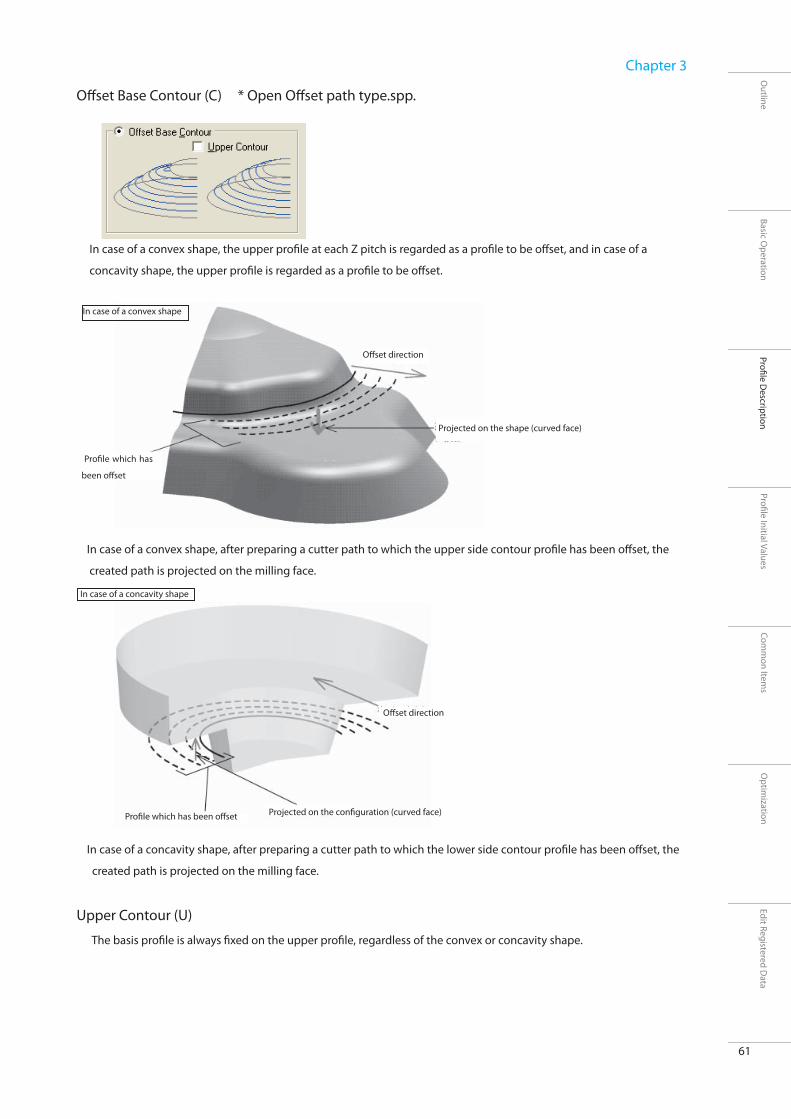
61
Outline
Basic Operation
Profi le Description
Optim
ization
Chapter 3
Profi le Initial ValuesCom
mon Item
sEdit Registered D
ata
Off set Base Contour (C) * Open Off set path type.spp.
In case of a convex shape, the upper profi le at each Z pitch is regarded as a profi le to be off set, and in case of a
concavity shape, the upper profi le is regarded as a profi le to be off set.
In case of a convex shape, after preparing a cutter path to which the upper side contour profi le has been off set, the
created path is projected on the milling face.
In case of a concavity shape, after preparing a cutter path to which the lower side contour profi le has been off set, the
created path is projected on the milling face.
Upper Contour (U)
The basis profi le is always fi xed on the upper profi le, regardless of the convex or concavity shape.
In case of a convex shape
Off set direction
Projected on the shape (curved face)
Profi le which has
been off set
In case of a concavity shape
Off set direction
Projected on the confi guration (curved face) Profi le which has been off set

62
Outline
Basic Operation
Profi le Description
Optim
ization
Chapter 3
Profi le Initial ValuesCom
mon Item
sEdit Registered D
ata
Both Contour (R)
Regardless of convex or concavity shape, both of upper and lower sides contours should be off set.
XY Step Over (P)
Input the off set pitch of basis contour (YX cross-section of a shape created by the cutting pitch in Z direction)
Upper side contour
Lower side contour
Crossing point of contour
To generate CL revolving after combining
upper and lower sides contour
Plane pitch

63
Outline
Basic Operation
Profi le Description
Optim
ization
Chapter 3
Profi le Initial ValuesCom
mon Item
sEdit Registered D
ata
Edge of Wall (E) * Open Edge of wall.spp
If you put a mark in the checkbox, you can set in such a manner the contour profi le is output in case any standing wall
shape should be present at the fl at portion during off set cut.
When edge of wall check has been switched OFF
Off set path
Off set path
Off set path
Off set path
Off set path Off set path
Contour pitch
Contour pitch
Contour pitch
Contour pitch
Because CL output at a contour pitch has been output to the position slightly above the bottom, uncut step occurs between off set paths.
When edge of wall check has been switched ON
Off set path
Off set path
Off set path
Off set path
Off set path
Off set path
Contour pitch
Contour pitch
Contour pitch
Contour pitch
When edge of wall has been output, no uncut portion appears because CL corresponding to the shape is output to the bottom height.
Ragged edge contour
Points to be noted when outputting edge of wall
Because the path of edge of wall is forcedly output, calculation may not be done satisfactorily depending on the shape. In case of a shape having many ragged edges like polygon, the time required for calculation may become very long. In such a case, perform ragged Edge Cutting through Edge Cutting.

64
Outline
Basic Operation
Profi le Description
Optim
ization
Chapter 3
Profi le Initial ValuesCom
mon Item
sEdit Registered D
ata
Delete Tool Path from Flat Regions (Valid only when contour off set path has been switched OFF) (N)
* Open Output angle (contour).spp.
Setting is made so that no Z-level should be output to the fl at face having smaller angle than specifi ed.
This is a function useful when carrying out fi nish milling of a fl at portion in another process (scanning line fi nish, fl at portion
revolution, etc).
* This is valid only when a ball tool has been selected.
Allowance (A)
When the specifi ed output angle has been input as “30°”, a path is
created only at the position having an angle of “30°” or more.
0° 16°
45°
60°
80°
Angle
An angle means an angle linking the contact point with a shape to the
tool front end based on the center of ball tool R as its axis.
Therefore, no angle limitation can be given to any fl at tool.
Allowance

65
Outline
Basic Operation
Profi le Description
Optim
ization
Chapter 3
Profi le Initial ValuesCom
mon Item
sEdit Registered D
ata
Approach/Connecting Move
This is a tab for setting the approach method and linkage movement method.
Approach
Specify the approach in the vertical direction or on a circle arc. Escape becomes an escape automatically linked to an
approach.
Vertical (V)
Approach is made in a vertical direction.
Circular (C)
Approach is made while drawing a circular arc.
Radius (R)
Radius of circular arc approach can be set.
Auto Adjustment (J)
Adjustment is made in such a manner that the circular arc radius of the approach to be inserted when the circular arc
approach has been specifi ed does not interfere with a workpiece.
Min. Radius
The circular arc radius of approach is adjusted to its minimum radius.
Tangent line escape
Tangent line approach
Vertical escape
Fast-forward
Vertical approach 1
Vertical approach 2
Fast-forward
Vertical approach 1
Vertical approach 2
Vertical escape

66
Outline
Basic Operation
Profi le Description
Optim
ization
Chapter 3
Profi le Initial ValuesCom
mon Item
sEdit Registered D
ata
Tool Path Connecting Move * Open Tool path connecting move.spp.
The movement method from Z-level to Z-level can be set.
When the off set cutting set by a tab “Z-level Property” has been switched ON, you can select a method from the following 2
methods.
Not Perform (D)
Moves to the starting position of next contour through the clearance height
Perform (E)
Moves by a linkage to the starting position of next Z-level
Approach: vertical Approach: circular arc
Approach: vertical Approach: circular arc

67
Outline
Basic Operation
Profi le Description
Optim
ization
Chapter 3
Profi le Initial ValuesCom
mon Item
sEdit Registered D
ata
When the off set cutting set by a tab “Z-level Property” has been switched OFF, you can select a method from the following 3
methods.
Not Perform (D)
Moves to the starting position of next contour through the clearance height
Perform (E)
Moves by a linkage to the starting position of next contour
Ramp on Face (S)
Moves by a linkage passing over the milling face to the starting position of next contour
When the "off set cutting" set by a tab “Z-level Property” has been switched ON, you cannot use this.

68
Outline
Basic Operation
Profi le Description
Optim
ization
Chapter 3
Profi le Initial ValuesCom
mon Item
sEdit Registered D
ata
Details * Open Tool path around wall 2.spp.
Linkage method of CL split depending on the cut off area or shape can be set.
Tool Path Around Wall * Open Tool path around wall 2.spp.
The linkage method can be specifi ed when the contour profi le is clipped by a workpiece edge or cutting range contour.
Along Plane(F)
Leaving the Z-level along the shape face, approach and escape can be added to the starting and ending positions.
The movement from an ending position to the starting position of next Z-level is performed at a clearance height.
Revolving (R)
When a Z-level has hit the workpiece edge or cutting range contour, milling is performed deeming the Z-level was closed
after transferring on to the contour.

69
Outline
Basic Operation
Profi le Description
Optim
ization
Chapter 3
Profi le Initial ValuesCom
mon Item
sEdit Registered D
ata
Cutting Concave Area * Open Area 2.spp.
Milling method can be specifi ed when multiple cutting concave areas exist in a shape.
Z-level Fixed (H)
Area is milling processed at each Z pitch.
Area Fixed (A)
Milling processed for each cutting concave areas.

70
Outline
Basic Operation
Profi le Description
Optim
ization
Chapter 3
Profi le Initial ValuesCom
mon Item
sEdit Registered D
ata
Tool coverage * Open Tool coverage (fi nishing).spp
Tool coverage against a contour of workpiece range or cut off area can be specifi ed. (CL between cutting sections)
Finish cut path output range
Under the precondition that the fi nish cut is staying at a state roughing process has been done (a state excessive thickness
of fi nish cut allowance is still remaining on the fi nal shape), a fi nish cut path is created. Therefore, a path is created
only on the surface of a model shape.
Inside of Contour (I)
CL is generated in the cutting section in such a manner the whole tool does not come out of cut off area contour.
Path output area
Approach/escape output area
(Workpiece range is sometimes exceeded.) Workpiece edge
Workpiece edge All CL ranges
Approach: Escape display is OFF.
Approach: Escape display is ON.

71
Outline
Basic Operation
Profi le Description
Optim
ization
Chapter 3
Profi le Initial ValuesCom
mon Item
sEdit Registered D
ata
Tool Center on Contour (L)
CL of cutting section is generated in a range the tool center is positioned on the cut
off area contour.
Outside of Contour (U)
CL of cutting section is generated in a range the whole tool comes out of cut off
area contour.
Off set from Contour (O)
The range the tool center moves from cut off area contour is directly specified
numerically.
All CL will be generated where the tool center does not come out of the specifi ed
off set range.
Distance
Off set amount from the cut off area contour will be created.
In milling mode other than roughing process, in other words, when (subject model shape + tool diameter) is within a
workpiece (within a cut off area), CL to be generated remains the same even when the tool movement range has been
changed.
As shown in the sketch below, when a shape cannot fully enter the workpiece or when you do not want to output any
approach or escape to outside of the workpiece (cut off area), change the tool movement range in a same manner as roughing
and adjust the range where CL is to be generated.
Workpiece profi le
All CL ranges

72
SRP Player Pro basic training text
Profi le Description
Outline
Basic Operation
Profi le Description
Optim
ization
Chapter 3
Profi le Initial ValuesCom
mon Item
sEdit Registered D
ata
Finishing (Scanning-Line)
Outline
Finishing (Scanning-Line)
In Finishing (Scanning-Line), CL will be generated which can perform milling as if copying the model shape in the plane,
vertical or horizontal direction in the project coordinate system.
In scanning line fi nish cut, a path will be created as if covering the model confi guration at the specifi ed pitch and specifi ed
running direction when the model confi guration is viewed from above.
In case of a curved face having a moderate slope in which you want to project a path parallel to the specified running
direction to a model shape, the amount of excessive thickness becomes constant. Therefore, the load applied to a tool is
also kept constant. Milling can be performed with less movement distance and within shorter time in approach or escape.
However, in case of any model shape having a corrugated shape, variation in Z direction becomes large and the removal of
excess thickness cannot be done at a constant rate. Therefore, depending on the position, there is a case milling load could be
heavily applied.

73
Outline
Basic Operation
Profi le Description
Optim
ization
Chapter 3
Profi le Initial ValuesCom
mon Item
sEdit Registered D
ata
Property
This is a tab for setting a pitch in the vertical (height) direction/plane direction/fi nish cut allowance.
Cut Off Range
Pitch (Step Over)
Allowance (A)
Finish cut allowance can be set.
Upper limit height
Lower limit height
Pitch distance
Pitch distance
A pitch distance can be set directly at an even pitch.
Height left projection
Cusp Height
The height of uncut angle (Cusp Height) can be set.
It becomes as an uneven pitch depending on the shape. (Impossible to input
when a fl at tool has been specifi ed)

74
Outline
Basic Operation
Profi le Description
Optim
ization
Chapter 3
Profi le Initial ValuesCom
mon Item
sEdit Registered D
ata
Traveling Type * Open Scanning line traveling type.spp.
This is a tab for setting a path creation method by scanning line.
Traveling Type
Path generation pattern can be set.
One-way (E)
A workpiece can be cut in a constant direction through a milling path parallel to the
direction specifi ed in the running direction.
When reaching the cut off area profi le, the tool moves keeping a clearance height to
the profi le at starting side of next pitch. The cutting direction becomes “Down cut”.
Bi-directional (R)
A workpiece can be cut in a reciprocating movement through a path parallel to the
direction specifi ed in the running direction.
When reaching the cut off area profi le, the tool moves over the profi le to the next
pitch.
The cutting direction becomes “Up and down cut”.
Tool Path Direction
The running direction in a path can be set. A path is created along X and Y axes in the project coordinate.
Reversal of running direction: The running direction in each X and Y axis can be reversed.
X-axis
CL will be generated in a direction parallel to X axis (in the project coordinate).
Y-axis
CL will be generated in a direction parallel to Y axis (in the project coordinate).
Reversal of runnning direction Reversal of runnning direction

75
Outline
Basic Operation
Profi le Description
Optim
ization
Chapter 3
Profi le Initial ValuesCom
mon Item
sEdit Registered D
ata
Angle (A)
Angle can be set in an anti-clockwise direction against the running direction in each X and Y axis.
The angle you can specifi ed is [- 180° Angle + 180°].
Approach
This is a tab for setting an approach.
Approach (A)
You can set an approach in a vertical direction or by tangent line. Escape becomes automatically an escape linked to
approach.
Vertical
Approach is performed in a vertical direction.
Tangential
A tangent line approach is performed in a specified length of tangent line.
Tangent line escape Tangent line approach
Vertical escape
Fast-forward
Vertical approach 1
Vertical approach 2
Vertical escape
Fast-forward
Vertical approach 1
Vertical approach 2

76
Outline
Basic Operation
Profi le Description
Optim
ization
Chapter 3
Profi le Initial ValuesCom
mon Item
sEdit Registered D
ata
Flat Regions * Open Output angle(running).spp
This is a tab for setting the method to create scanning line path.
By switching the checkbox to ON, you can set so that no scanning line is output to the standing wall having an angle
exceeding the specifi ed angle by fl at regions judgment angle (Angle). This is helpful when performing fi nish cut milling of
the standing wall in a separate process (contour milling).
Angle (A)
The area having an angle smaller than this angle is deemed as a fl at region.
In order for this area to overlap the contour fi nish cut territory, set the output range angle larger than the output range
angle specifi ed by the contour output angle for contour fi nish cut.
Escape Allowance (E)
When any standing wall should exist in a shape, it may be rubbed during approach or escape. In such a case, a path
performing approach/escape from a position apart from the standing wall [by escaping allowance] can be created.
0° 16° 45°
60°
80°
Escape allowance Escape allowance
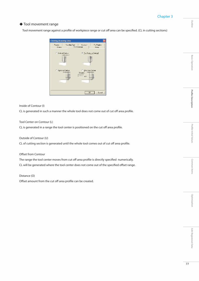
77
Outline
Basic Operation
Profi le Description
Optim
ization
Chapter 3
Profi le Initial ValuesCom
mon Item
sEdit Registered D
ata
Tool movement range
Tool movement range against a profi le of workpiece range or cut off area can be specifi ed. (CL in cutting sections)
Inside of Contour (I)
CL is generated in such a manner the whole tool does not come out of cut off area profi le.
Tool Center on Contour (L)
CL is generated in a range the tool center is positioned on the cut off area profi le.
Outside of Contour (U)
CL of cutting section is generated until the whole tool comes out of cut off area profi le.
Off set from Contour
The range the tool center moves from cut off area profi le is directly specifi ed numerically.
CL will be generated where the tool center does not come out of the specifi ed off set range.
Distance (O)
Off set amount from the cut off area profi le can be created.

78
SRP Player Pro basic training text
Profi le Description
Outline
Basic Operation
Profi le Description
Optim
ization
Chapter 3
Profi le Initial ValuesCom
mon Item
sEdit Registered D
ata
Edge Cutting
Outline
Edge Cutting
Using a fl at tool, detect any ragged edge.
By automatically detecting any ragged edge, create a cutter path for fl at face.

79
Outline
Basic Operation
Profi le Description
Optim
ization
Chapter 3
Profi le Initial ValuesCom
mon Item
sEdit Registered D
ata
Allowance/approach * Open Edge.spp.
This is a tab for setting the fi nish cut allowance and approach.
Allowance (F)
Finishing allowance can be set.
Approach (A)
You can set approach vertically or in circular arc. Escape automatically becomes escape linked to approach.
Vertical
Approach can be made in vertical direction.
Circular
Approach is made like drawing a circular arc.
Radius (R)
Radius of circular arc approach can be set.

80
Outline
Basic Operation
Profi le Description
Optim
ization
Chapter 3
Profi le Initial ValuesCom
mon Item
sEdit Registered D
ata
Step Down
This is a tab for setting the method of path creation in the height (drive in) direction.
Milling is started from a higher position by “Step Down” x “Repeat Count” and a path is created by the
number of times of drive in.
Repeat Count (C)
Number of times of drive in Z direction can be specifi ed.
Step Down (P)
Drive in pitch in Z direction can be specifi ed.
Step Down
Repeat Count

81
Outline
Basic Operation
Profi le Description
Optim
ization
Chapter 3
Profi le Initial ValuesCom
mon Item
sEdit Registered D
ata
Tool Coverage
Tool coverage against a profi le of workpiece range or cut off area can be specifi ed. (CL in cutting sections)
Inside of Contour (I)
CL is generated in such a manner the whole tool does not come out of cut off area contour.
Tool center on Contour (L)
CL is generated in a range the tool center is positioned on the cut off area profi le.
Outside of Contour (U)
CL of cutting section is generated until the whole tool comes out of cut off area contour.
Off set from Contour (O)
The range the tool center moves from cut off area contour is directly specifi ed numerically .
CL will be generated where the tool center does not come out of the specifi ed off set contour.
Distance
Off set amount from the cut off area contour can be created.

82
SRP Player Pro basic training text
Profi le Description
Outline
Basic Operation
Profi le Description
Optim
ization
Chapter 3
Profi le Initial ValuesCom
mon Item
sEdit Registered D
ata
Curve Cutting
Outline
Curve Cutting
In curve cutting , CL will be generated based on a cutting curve having starting point and direction created according to
the curve.
Diff erent from other cutting modes, it is necessary to specify a subject cutting curve.
It is possible to specify multiple cutting curves based on a single profi le.
For CL generated by curve cutting, no check will be made for any interference of a model shape with polygon or curved face.
CL will be generated based on a cutting curve.

83
Outline
Basic Operation
Profi le Description
Optim
ization
Chapter 3
Profi le Initial ValuesCom
mon Item
sEdit Registered D
ata
What is curve cutting?
Milling is carried out using curves of the portion of a model shape not expressed by polygon or curved face.
The curves subject to milling should be created in advance (by CAD/CG software).
For CL generated by curve cutting, no check will be made for any interference of a model shape with polygon or curved face.
CL will be generated based on the cutting curve.
0. Before starting workpiece
Read the curves created (by CAD/CG software).
1. Creation of a workpiece and project
2. Creation of a profi le for curve cutting
A profi le of curve cutting is created.
3. Creation of cutting curve
“Cutting curve” is created.
4. Specifi cation of cutting curve
Curve subject to cut is specifi ed.
5. Decision of cutting curve
Cutting curve is fi xed.
6. Execution of calculation
CL is generated.
7. Checking of shape
Result of simulation is checked.
Edition of cutting curve
Created cutting curve is edited for the orientation reverse of a curve, movement from starting point, etc.

84
Outline
Basic Operation
Profi le Description
Optim
ization
Chapter 3
Profi le Initial ValuesCom
mon Item
sEdit Registered D
ata
Traveling Type * Open Curve.spp.
This is a tab for setting a path route (traveling type).
Traveling Type
One-way (E)
The cut direction is always in one way.
Bi-derectional (R)
When 2 or more numbers of depth cut have been defi ned, the cut direction is changed for each cut off range. The fi nal cut
face follows the defi ned starting point and cut direction. (Round cut)

85
Outline
Basic Operation
Profi le Description
Optim
ization
Chapter 3
Profi le Initial ValuesCom
mon Item
sEdit Registered D
ata
Step Down
This is a tab for setting the path output range of curve cutting.
Top (T)
The height the curve cutting should start can be set. CL will be clipped so that this height is not exceeded.
Bottom (B)
This is the height when the curve cutting ends. CL less than this height will be clipped.
Repeat Count (C)
The number of times of depth cut can be specifi ed within the cut off range.
Step Down (P)
A pitch of depth cut in Z direction can be specifi ed. (Valid when specifi ed to the number of times of depth cut only)
Allowance (A)
Finish cut allowance can be set. (Finish cut allowance is added to the height direction only.)
Top
BottomRepeat Count
Step Down

86
Outline
Basic Operation
Profi le Description
Optim
ization
Chapter 3
Profi le Initial ValuesCom
mon Item
sEdit Registered D
ata
Height diff erence in paths created by a tool used
A path is created along the cutting curve line to which tool center has been specifi ed.
Because the heights of the center of a ball tool and fl at tool are not the same, the path heights to be created are not the
same even when the subject cutting curve and tool diameter are the same.
A ball tool
Upper face
Tool center
Front
A fl at tool
Upper face
Tool center
Front
Cutting curve
Path position
Cutting curve
Path position

Profi le Initial Values

SRP Player Pro basic training text
Profi le Initial Values
88
Outline
Basic Operation
Profi le Description
Optim
ization
Chapter 4
Profi le Initial ValuesCom
mon Item
sEdit Registered D
ata
About profi le initial values
What is profi le initial value?
This is an initial value of a set value in each milling mode. There are 2 types of initial values, one is a Default and the other is a
Factor.
Default
This is an item automatically set when a profi le has been created. When a Default is a numerical value, it is directly
set numerically. When a Default is a letter, click the setting to be changed and select from the pull down menu.
Factor
This depends on the tool diameter or feed speed. A value obtained by multiplying each item by Factor is used as an initial
value.
This change does not aff ect the profi le already created.
The initial value set from a created profi le is refl ected after editing the profi le initial value.
Set of Initial values
Initial value is controlled by “set of initial values” which has put all modes together, and not controlled by each mode of a
profi le.The profi le initial value is segmented for each milling machine or by milling accuracy unit, etc and the user is set.
Limitation:
You cannot delete initial value set “Default”.
If you right-click on the initial value set screen, you
can perform “New”, “Duplicate”, “Rename” or “Delete”.

89
Outline
Basic Operation
Profi le Description
Optim
ization
Chapter 4
Profi le Initial ValuesCom
mon Item
sEdit Registered D
ata

SRP Player Pro basic training text
Profi le Initial Values
90
Outline
Basic Operation
Profi le Description
Optim
ization
Chapter 4
Profi le Initial ValuesCom
mon Item
sEdit Registered D
ata
Roughing (Z-level)

91
Outline
Basic Operation
Profi le Description
Optim
ization
Chapter 4
Profi le Initial ValuesCom
mon Item
sEdit Registered D
ata
Profi le initial value of roughing (Z-level)
This is an initial value of the set value in the roughing mode. There are 2 types of initial values, one is a Default and the other is
a Factor.
Default
When a Default is numerical value, change it by setting a numerical value directly by double clicking the value to be changed.
When a Default is letter,
click the setting to be changed and select from pull down menu.
Off setting
Perform: After off setting the curved face, obtain the cross point with Z-value of tool center and specify that cross-point as
the tool position.Although the calculation of a tool path can be done quickly, the calculation can be easily aff ected
by the accuracy of curved face.
Not Perform: After dropping a tool from straight above, calculate the point it hit the curved face and specify that point as
the tool position.Although the calculation of a tool cannot be done quickly, the calculation cannot be easily
aff ected by the accuracy of curved face.
Number of Divisions
This is the number of splits used when cut corners fi rst has been selected in the corner pre-milling.
There is no need to change it in normal operation.
Step to Detect Cavity/Core Part
You can set the amount of a step when checking the shape to determine whether the shape subject to
milling is a cavity (concavity) or a core (convex). In case of a shape in which similar concavity shapes are seemingly
lined-up, or in case location where no CL should be output and location where some CL output are present, change this
numerical fi gure.
Name (Default) DescriptionOff setting The method to calculate tool path can be specified. This method is only available when the
milling subject is a curved face.Number of Divisions Number of splits of calculation to be used when "cut corners fi rst" can be selected in the corner
pre-milling
No need to change it in normal operation.Step to Detect Cavity/Core Part A step amount is to be set when checking the shape to determine whether the shape subject to
milling is a cavity (concavity) or a core (convex).Tolerance for Reduction A range can be set for determining whether or not the direction is the same when performing
reductionLength of Vertical Approach 1 The length of vertical approach 1 can be set.Ignore Min. Contour Length Whether or not the profi le length should be judged during helical cut depth can be specifi ed.Chordal Deviation Chordal deviation is a split accuracy of a curved face when calculating a tool path.Judgement Angle (Tolerance of Curvature) When the direction should come off from present direction during calculation of next moving
point, the calculation should be made in further details or the angle subject to judgment is set
by a judgement angle. Tolerance (Tolerance of Curvature) The minimum distance when splitting can be set through a step of curvature accuracy.

92
Outline
Basic Operation
Profi le Description
Optim
ization
Chapter 4
Profi le Initial ValuesCom
mon Item
sEdit Registered D
ata
Tolerance for Reduction
You can set the range for determining whether or not the direction is the same when performing reduction.
If you set the reduction value larger, the determination whether or not the direction is the same becomes permissive and
you can reduce the data volume because the number of halfway moving points is reduced. However, even when the track
of a path has changed largely as a result of reduction, no interference check will be performed for the shape.
Value between 0.00004 and 0.00394 is a recommendable use range.
Ignore Min. Contour Length
Whether or not the contour length should be judged during helical depth cut can be specifi ed.
Perform: Disregarding the specifi ed minimum profi le length, helical depth cut is always output.
Not Perform: helical depth cut smaller than the minimum profi le length is not output.
Chordal Deviation
This is a value for specifying the calculation accuracy in the tool advancing direction (XY directions).
For a path, calculate the step amount which should become the standard to keep the chordal deviation, assuming that the
curvature of a curved face is R3.937.
The path to be created is linear data. Because convex shape is “cutout” and concavity shape is “left uncut”,
adjust the amount of “cutout” and “left uncut” according to the length of linear step amount.
For example, there is CL information having 6 branching points before reduction.
In case the branching points from 1 to 5 are within a permissible range, when this CL information is passed through
reduction milling and the permissible range in which reduction has been specifi ed (reduction value cylinder);
Reduction value: When set at 0.00039
Linear data milling is performed for 1 block by getting together the data groups (branching points of 1 through 5) within the permissible range.
As shown above, there is a case the path in a single section becomes long by reduction milling resulting in a rough path.
Change the set value if necessary.
* Re-calculation becomes necessary for changing the reduction value.
0.00039

93
Outline
Basic Operation
Profi le Description
Optim
ization
Chapter 4
Profi le Initial ValuesCom
mon Item
sEdit Registered D
ata
Relationship between “cutout” and “left uncut” according to the length of step amount
When the step amount is large, the volume of “cutout/left uncut” becomes large.
When the step amount is small, the volume of “cutout/left uncut” becomes small.
Chordal deviation value and step amount
For example, if chordal deviation is set at “0.0197” when a tool with a size of ψ 0.3937 inch is moving around
R3.937 circular arc, the step amount will become 0.1748 inch.
Chordal deviation value and milling accuracy
The value set for chordal deviation is the value of angle height left uncut (cusp height) in the tool,
supposing that a tool before movement and after movement is placed there. Step amount is calculated in
such a manner this projection height left uncut is maintained. The amount of “cutout” and “left
uncut”, occurring when the tool moved on the surface with that step amount, is the milling accuracy.
In the example (when a tool with a size of ψ 0.3937 inch is moving around R3.937 circular arc);
Chordal deviation “0.0197 inch”/Step amount: “0.1748 inch”/Milling accuracy: “0.0008 inch”
Step amount: 0.1748 inch
Chordal deviation: 0.0197 inch
Line of a shape actually being cutMilling accuracy: 0.0008 inch
0.1748
R3.937ψ 0.3937
0.01
97

94
Outline
Basic Operation
Profi le Description
Optim
ization
Chapter 4
Profi le Initial ValuesCom
mon Item
sEdit Registered D
ata
Curvature accuracy
The step amount calculated according to chordal deviation is preconditioned that the curvature of the shape
subject to milling has been kept constant. In case of any point where the curvature has been changed largely, the path also
makes a rapid change on a single curved face.
When such a change should occur to the curvature, the step amount is changed up to the specifi ed accuracy value, in order
to prevent the accuracy from becoming low due to the change of vector.
Judgement Angle (Tolerance of Curvature)
This is a permissible value of an angle of vector change in a path on a single curved face.
Tolerance (Tolerance of Curvature)
The boundary length of step amount is to be specifi ed to determine in what details the calculation should be made.
For example, when moving to the next step and if the angle diff erence “A” from the previous path track is larger than the
“angle value” specifi ed in the curvature accuracy;
Reduce the distance of step amount (L) to its half and change it so that the change of angle becomes smaller.
Even when the distance has been reduced to its half and if “angle A” is still larger than the specifi ed value, further reduce the step amount (L) to its half and
calculate so that the angle should fall within the “angle value”.
When the step amount (L) has reached its boundary length after repeating the checks and calculation of above angle change, stop the calculation of angle
change to determine the position of next step amount.

95
Outline
Basic Operation
Profi le Description
Optim
ization
Chapter 4
Profi le Initial ValuesCom
mon Item
sEdit Registered D
ata
Reliance relationship
Tool diameter x Factor
Max Horisontal Pitch
Max Vertical Pitch
Step Down
Step Over
Min. Contour Length
Length of Vertical Approach 2
Radius of Circular Approach
Length of Tangential Approach
Rate of Vertical Escape
Feed rate x Factor
Rate of Helical Approach
Rate of Vertical Approach 1
Length of Vertical Approach 2
Rate of Circular / Tangential Approach
Rate of Vertical Escape
Rate of Cutting Vertices of Corners First
Rate of Cutting Remainder in Acute Angle Section
Rate of Approaching Remaindered Flat Area
Factor
Double click the value and change it by setting a numerical value directly
Name (Factor) Description
Max Horisontal Pitch Maximum pitch in the plane direction
Max Vertical Pitch Maximum pitch height in the vertical direction
Step Down A pitch for setting to the profi le in the vertical direction can be set.
Step Over A pitch for setting to the profi le in the plane direction can be set.
Rate of Helical Approach Feed speed during helical depth cut can be set.
Min.Contour Length The minimum length of the profi le during helical depth cut can be set.
Rate of Vertical Approach 1 The speed of vertical approach 1 can be set.
Length of Vertical Approach 2 The length of vertical approach 2 can be set.
Rate of Vertical Approach 2 The speed of vertical approach 2 can be set.
Radius of Circular Approach The circular arc radius can be set when circular arc approach has been set.
Length of Tangential Approach The approach length can be set when tangent line approach has been set.
Rate of Circular/Tangential Approach The speed during circular arc approach or tangent line approach can be set.
Length of Vertical Escape The length of vertical escape can be set.
Rate of Vertical Escape The speed of vertical escape can be set.
Rate of Cutting Vertices of Corners First The cut speed during corner pre-milling can be set.
Rate of Cutting Remainder in Acute Angle Section The cut speed of the corner uncut portion milling can be set.
Rate of Approaching Remaindered Flat Area The approach speed of the uncut fl at portion milling can be set.
Example of set value (Tool diameter: 0.1969)
Factor “0.5” x ψ 0.1969 = Set value “0.0985”
Factor “1.5” x ψ 0.1969= Set value “0.2954”
Factor “0.2” x ψ 0.1969= Set value “0.0394”
Factor “0.4” x ψ 0.1969 = Set value “0.0788”
Factor “2.0” x ψ 0.1969 = Set value “0.3938”
Factor “0.5” x ψ 0.1969 = Set value “0.0985”
Factor “0.5” x ψ 0.1969 = Set value “0.0985”
Factor “0.5” x ψ 0.1969 = Set value “0.0985”
Factor “1.0” x ψ 0.1969= Set value “0.1969”
Example of set value (Feed rate: 800 mm/min)
Factor “0.3” x 800 mm/min = Set value “240mm/min”
Factor “0.3” x 800 mm/min = Set value “240mm/min”
Factor “0.3” x 800 mm/min = Set value “240mm/min”
Factor “1.0” x 800 mm/min = Set value “800mm/min”
Factor “1.0” x 800 mm/min = Set value “800mm/min”
Factor “0.6” x 800 mm/min = Set value “480mm/min”
Factor “1.0” x 800 mm/min = Set value “800mm/min”
Factor “1.0” x 800 mm/min = Set value “800mm/min”

SRP Player Pro basic training text
Profi le Initial Values
96
Outline
Basic Operation
Profi le Description
Optim
ization
Chapter 4
Profi le Initial ValuesCom
mon Item
sEdit Registered D
ata
Finishing (Z-level)

97
Outline
Basic Operation
Profi le Description
Optim
ization
Chapter 4
Profi le Initial ValuesCom
mon Item
sEdit Registered D
ata
Profi le initial values for contour fi nishing (Z-level)
This is an initial value of the set value in the contour fi nishing (Z-level) mode. There are 2 types of initial values, one is a Default
and the other is a Factor.
Default
When a Default is a numerical value, change it by setting a numerical value directly by double clicking the value to be
changed.
When a Default is a letter,
click the setting to be changed and select from pull down menu.
Off setting
Perform: After off setting the curved face, obtain the cross point with Z-value of tool center and specify that cross-point as
the tool position.
Although the calculation of a tool path can be done quickly, the calculation can be easily aff ected by the accuracy of curved
face.
Not Perform: After dropping a tool from straight above, calculate the point it hit the curved face and specify that point as
the toolposition.
Although the calculation of a tool cannot be done quickly, the calculation cannot be easily aff ected by the accuracy of
curved face.
Step to Detect Cavity/Core Part
You can set the amount of a step when checking the shape to determine whether the shape subject to
milling is a cavity (concavity) or a core (convex). In case of a shape in which similar concavity shapes are seemingly
lined-up, or in case location where no CL should be output and location where some CL output are present, change this
numerical fi gure.
Length of helical part
When circular arc approach is unable to be made or in case of a movement on the face in the tangent line movement, it
becomes helical depth cut. This value is used for the approach length. When you do not want an automatic helical depth
cut, set to 0.0.
Name (Default) Description
Off setting The method to calculate tool path can be specifi ed. This method is only available when the milling subject is a curved
face.
Step to Detect Cavity/Core Part A step amount is to be set when checking the shape to determine whether the shape subject to milling is a cavity
(concavity) or a core (convex).
Tolerance for Reduction The range can be set for determining whether or not the direction is the same when performing reduction
Length of Vertical Approach 1 The length of vertical approach 1 can be set.
Length of Helical Part (Z-level Finishing) The length when the approach is for helical depth cut can be set.
Chordal Deviation Chordal deviation is a split accuracy of a curved face when calculating a tool path.
Judgement Angle(Tolerance of Curvature) When the direction should come off from present direction during calculation of next moving point, the calculation
should be made in further details or the angle subject to judgment is set by a judgement angle.
Tolerance (Tolerance of Curvature) The minimum distance when splitting is set by a step of curvature accuracy.

98
Outline
Basic Operation
Profi le Description
Optim
ization
Chapter 4
Profi le Initial ValuesCom
mon Item
sEdit Registered D
ata
Factor
Double click the value and change it by setting a numerical value directly.
Example of set value (Tool diameter: 0.1181, Cusp height: 0.0001)
Numerical value obtained from cusp height 0.0001 x Safety factor 0.7 = Set
value “0.0043”
Example of set value (Tool diameter: 0.1181)
Factor “0.5” x ψ 0.1181 = Set value “0.0591”
Factor “1.5” x ψ 0.1181= Set value “0.1772”
Factor “0.1” x ψ 0.1181 = Set value “0.0118”
Factor “0.0” x ψ 0.1181 = Set value “0.0”
Factor “0.5” x ψ 0.1181 = Set value “0.0591”
Factor “0.5” x ψ 0.1181 = Set value “0.0591”
Factor “0.1” x ψ 0.1181 = Set value “0.0118”
Factor “1.0” x ψ 0.1181 = Set value “0.1181”
Example of set value (Feed rate: 800 mm/min)
Factor “1.0” x 800 mm/min = Set value “800mm/min”
Factor “1.0” x 800 mm/min = Set value “800mm/min”
Factor “0.3” x 800 mm/min = Set value “240mm/min”
Factor “0.3” x 800 mm/min = Set value “240mm/min”
Factor “1.0” x 800 mm/min = Set value “800mm/min”
Factor “1.0” x 800 mm/min = Set value “800mm/min”
Factor “0.3” x 800 mm/min = Set value “240mm/min”
Factor “1.0” x 800 mm/min = Set value “800mm/min”
Factor “0.8” x 800 mm/min = Set value “640mm/min”
Name (Factor) Description
Cusp height This is used in a calculation by safety factor.
Max Off set Pitch Maximum value of off set pitch in the contour off set path
Max Vertical Pitch Maximum vertical pitch height
Step Down A pitch in the vertical direction to be set to a profi le can be set.
Step Over An off set pitch of contour off set path to be set to a profi le can be set.
Cutting Rate in XY Direction The speed of contour off set path can be set.
Cutting Rate of Connecting Move The speed during movement in linkage can be set.
Min. Contour Length In case of an occurrence of a path shorter than the value specifi ed here, that path will be deleted.
Rate of Vertical Approach 1 The speed of vertical approach 1 can be set.
Length of Vertical Approach 2 The length of vertical approach 2 can be set.
Rate of Vertical Approach 2 The speed of vertical approach 2 can be set.
Rate of Circular Approach The circular arc radius can be set when circular approach has been set.
Radius of Circular Approach The approach length can be set when tangent line approach has been set.
Min. Radius of Circular Approach The minimum radius of circular arc approach can be set.
Rate of Connecting Move in XY Direction The moving speed in XY plane directions during movement in linkage can be set.
Rate of Connecting Move in Z Direction The moving speed in the vertical direction during movement in likage can be set.
Length of Vertical Escape The vertical escaping length can be set.
Rate of Vertical Escape The vertical escaping speed can be set.
Rate of Helical Approach Feed speed during helical depth cut can be set.
Reliance relationship
Safety rate x Factor
Step Over
Tool diameter x Factor
Max Off set Pitch
Max Vertical Pitch
Step Down
Min. Contour Length
Length of Vertical Approach 2
Circular arc approach radius
Minimum radius of circular arc approach
Vertical escaping length
Feed rate x Factor
Cut speed in the plane direction
Cut speed of linkage point
Vertical approach speed 1
Vertical approach speed 2
Rate of Circular Approach
Rate of Connecting Move in XY Direction
Rate of Connecting Move in Z Direction
Rate of Vertical Escape
Rate of Helical Approach

SRP Player Pro basic training text
Profi le Initial Values
99
Outline
Basic Operation
Profi le Description
Optim
ization
Chapter 4
Profi le Initial ValuesCom
mon Item
sEdit Registered D
ata
Finishing (Scanning-line)

100
Outline
Basic Operation
Profi le Description
Optim
ization
Chapter 4
Profi le Initial ValuesCom
mon Item
sEdit Registered D
ata
Profi le initial values of Finishing (Scanning-line)
This is an initial value of the set value in the contour fi nish cut mode. There are 2 types of initial values, one is a Default and the
other is a Factor.
Default
When a Default is a numerical value, change it by setting a numerical value directly by double clicking the value to be
changed.
When a Default is a letter,
click the setting to be changed and select from pull down menu.
Off setting
Perform: After off setting the curved face, obtain the cross point with Z-value of tool center and specify that cross-point as
the tool position.
Although the calculation of a tool path can be done quickly, the calculation can be easily aff ected by the accuracy of curved
face.
Not Perform: After dropping a tool from straight above, calculate the point it hit the curved face and specify that point as
the tool position.
Although the calculation of a tool cannot be done quickly, the calculation cannot be easily aff ected by the accuracy of
curved face.
Judgement Angle for Shifting
When another curved face has become the subject from the curved face of which path is being calculated, a split angle can
be set for calculating a milling path of the linkage point of a curved face and another curved face. Set this angle in a fi nest
fashion so that the appearance of linked portion becomes fair.
Tolerance for Shifting
A boundary length can be set for positioning the linkage point of a curved face with another curved face.
Name (Default) Description
Off setting The method to calculate tool path can be specifi ed. This method is only available when the milling subject is a
curved face.
Judgement Angle for Shifting When another curved face has become the subject from the curved face of which path is being calculated, a
split angle can be set for calculating a milling path of the linkage point of a curved face and another curved
face.
Tolerance for Shifting A boundary length can be set for positioning the linkage point of a curved face with another curved face.
Tolerance for Reduction The range can be set for determining whether or not the direction is the same when performing reduction.
Length of Vertical Approach 1 The length of vertical approach 1 can be set.
Chordal deviation Chordal deviation is a split accuracy of a curved face when calculating a tool path.
Judgement Angle(Tolerance of Curvature) When the direction should come off from present direction during calculation of next moving point, the
calculation should be made in further details or the angle subject to judgment is set by an angle of curvature
accuracy.
Tolerance (Tolerance of Curvature) The minimum distance when splitting can be set by a step of curvature accuracy.

101
Outline
Basic Operation
Profi le Description
Optim
ization
Chapter 4
Profi le Initial ValuesCom
mon Item
sEdit Registered D
ata
Reliance relationship
Safety rate x Factor
Step Over
Tool diameter x Factor
Max Pitch Length
Length of Vertical Approach 2
Length of Tangential Approach
Length of Vertical Escape
Feed rate x Factor
Rate of Vertical Approach 1
Rate of Vertical Approach 2
Rate of Tangential Approach
Rate of Vertical Escape
Factor
Double click the value and change it by setting a numerical value directly.
Name (Factor) Description
Cusp Height This is used in a calculation with safety factor.
Max Pitch Length Maximum value of a pitch in the plane direction
Step Over A pitch in the plane direction to be set to a profi le can be set.
Rate of Vertical Approach 1 The speed of vertical approach 1 can be set.
Length of Vertical Approach 2 The length of vertical approach 2 can be set.
VeRate of Vertical Approach 2 The speed of vertical approach 2 can be set.
Length of Tangential Approach The length of tangent line approach can be set.
Rate of Tangential Approach The speed of tangent line approach can be set.
Length of Vertical Escape The length of vertical escape can be set.
Rate of Vertical Escape The speed of vertical escape can be set.
Example of set value (Tool diameter: 0.1181, Cusp height: 0.0001)
Numerical value obtained from uncut projection 0.002 x Safety factor 0.7 =
Set value “0.0043”
Example of set value (Tool diameter: 0.1181)
Factor “0.5” x ψ 0.1181 = Set value “0.0591”
Factor “0.5” x ψ 0.1181 = Set value “0.0591”
Factor “0.5” x ψ 0.1181= Set value “0.0591”
Factor “0.5” x ψ 0.1181= Set value “0.0591”
Example of set value (Feed rate: 800 mm/min)
Factor “0.3" x 800 mm/min = Set value “240mm/min”
Factor “0.3” x 800 mm/min = Set value “240mm/min”
Factor “1.0” x 800 mm/min = Set value “800mm/min”
Factor “1.0” x 800 mm/min = Set value “800mm/min”

SRP Player Pro basic training text
Profi le Initial Values
102
Outline
Basic Operation
Profi le Description
Optim
ization
Chapter 4
Profi le Initial ValuesCom
mon Item
sEdit Registered D
ata
Edge Cutting

103
Outline
Basic Operation
Profi le Description
Optim
ization
Chapter 4
Profi le Initial ValuesCom
mon Item
sEdit Registered D
ata
Profi le initial values of edge cutting
This is an initial value of the set value in the Edge cutting mode. There are 2 types of initial values, one is a Default and the
other is a Factor.
Default
When a Default is a numerical value, change it by setting a numerical value directly by double clicking the value to be
changed.
When a Default is a letter,
click the setting to be changed and select from pull down menu.
Off setting
Perform: After off setting the curved face, obtain the cross point with Z-value of tool center and specify that cross-point as
the tool position.
Although the calculation of a tool path can be done quickly, the calculation can be easily aff ected by the accuracy of curved
face.
Not Perform: After dropping a tool from straight above, calculate the point it hit the curved face and specify that point as
the tool position.
Although the calculation of a tool cannot be done quickly, the calculation cannot be easily aff ected by the accuracy of
curved face.
Edge Detection Angle/Edge Detection Gap volume
The detection of a portion subject to the milling can be set by an angle and gap. After judging by an angle, a milling path
will be output to the portion having the same step as the gap amount.
If this angle is made too small, only a shape having a steep angle can be obtained, whereas if made large enough,
the moderate shape portion will be recognized as a subject of milling.
Name (Default) Description
Off setting The method to calculate tool path can be specifi ed. This method is only available when the milling subject is a curved face.
Tolerance for Reduction The range can be set for determining whether or not the direction is the same when performing reduction.
Edge Detection Angle The detection of a portion subject to the milling can be set by an angle and gap. After judging by an angle, a milling path
will be output to the portion having the same step as the gap amount.Edge Detection Gap volume
Judgement angle This is a function to output the path only which is within the angle in the range specifi ed by a milling path which has been
created by edge detection angle and gap.
Judgement angle value Judging angle can be set for use in the judgment of path output angle.
Length of Vertical Approach 1 Vertical approach length 1 can be set.
Chordal Deviation Chordal deviation is a split accuracy of a curved face when calculating a tool path.
Judgement Angle( Tolerance of
Curvature)
When the direction should come off from present direction during calculation of next moving point, the calculation should
be made in further details or the angle subject to judgment is set by an angle of curvature accuracy.
Tolerance (Tolerance of Curvature) The minimum distance when splitting is set by a step of curvature accuracy.

104
Outline
Basic Operation
Profi le Description
Optim
ization
Chapter 4
Profi le Initial ValuesCom
mon Item
sEdit Registered D
ata
Edge detection
When the angle made by slope lines on the curved face which is separated by gap amount from the portion where the
angle changes rapidly is larger than the edge detection angle, such a portion is determined as a subject of milling. A milling
path is created by tracking that portion.
Judgement angle value
It is required that the angle from a horizontal portion is within the path output angle in order to create a path at the portion
detected by detection angle.
When determined that the path output angle has been exceeded, no milling path will be output to that portion.
Edge Detection Gap volume
The step less than the edge detection gap volume cannot be detected.
If the edge detection gap amount has been set too large, there may be a portion to which no path is output.
If the edge detection gap volume has been set too small, a path may be output to the portion having no step due to
calculation error.
Portion subject to milling
Horizontal
Horizontal

105
Outline
Basic Operation
Profi le Description
Optim
ization
Chapter 4
Profi le Initial ValuesCom
mon Item
sEdit Registered D
ata
Factor
Double click the value and change it by setting a numerical value directly.
Reliance relationship
Tool diameter x Factor
Max Height depth of Cut
Spacing to Detect Ridgeline
Step Down
Length of Vertical Approach 2
Radius of Circular Approach
Min. Radius of Circular Approach
Approach Safety Distance
Length of Vertical Escape
Feed rate x Factor
Rate of Vertical Approach 1
Rate of Vertical Approach 2
Rate of Circular Approach
Rate of Connecting Move in XY Direction
Rate of Connecting Move in Z Direction
Rate of Vertical Escape
Name (Factor) Description
Max Height depth of Cut Maximum value of height drive in pitch
Spacing to Detect Ridgeline A distance to detect the edge line for preparing a path can be set from a shape.
Step Down A distance to the next cutting section path can be set after the number of times of drive in has been set.
Rate of Vertical Approach 1 The speed of vertical approach 1 can be set.
Length of Vertical Approach 2 The length of vertical length 2 can be set.
Rate of Vertical Approach 2 The speed of vertical approach 2 can be set.
Rate of Circular Approach The speed during circular arc approach can be set.
Radius of Circular Approach The circular arc radius can be set when circular arc approach has been set.
Min. Radius of Circular Approach The minimum radius of circular arc approach can be set.
Approach Safety Distance A distance to prevent workpiece interference can be set from approach starting point to cut starting point.
Rate of Connecting Move in XY Direction Moving speed in XY plane directions during movement in linkage can be set.
Rate of Connecting Move in Z Direction Moving speed in the vertical direction during movement in linkage can be set.
Length of Vertical Escape The length of vertical escape can be set.
Rate of Vertical Escape The speed of vertical escape can be set.
Example of set value (Tool diameter: 0.1181)
Factor “0.5” x ψ 0.1181 = Set value “0.1772”
Factor “0.2” x ψ 0.1181 = Set value “0.0236”
Factor “0.3” x ψ 0.1181 = Set value “0.0354”
Factor “0.5” x ψ0.1181= Set value “0.0591”
Factor “0.5” x ψ0.1181 = Set value “0.0591”
Factor “0.2” x ψ 0.1181 = Set value “0.0236”
Factor “0.1” x ψ 0.1181= Set value “0.0118”
Factor “1.0” x ψ 0.1181 = Set value “0.1181”
Example of set value (Feed rate: 800 mm/min)
Factor “0.3” x 800 mm/min = Set value “240mm/min”
Factor “1.0” x 800 mm/min = Set value “800mm/min”
Factor “1.0” x 800 mm/min = Set value “800mm/min”
Factor “1.0” x 800 mm/min = Set value “800mm/min”
Factor “0.3” x 800 mm/min = Set value “240mm/min”
Factor “1.0” x 800 mm/min = Set value “800mm/min”

SRP Player Pro basic training text
Profi le Initial Values
106
Outline
Basic Operation
Profi le Description
Optim
ization
Chapter 4
Profi le Initial ValuesCom
mon Item
sEdit Registered D
ata
Curve Cutting
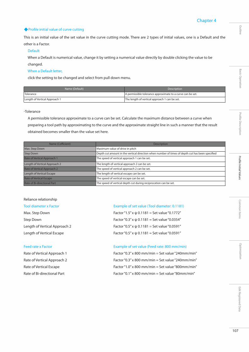
107
Outline
Basic Operation
Profi le Description
Optim
ization
Chapter 4
Profi le Initial ValuesCom
mon Item
sEdit Registered D
ata
Profi le initial value of curve cutting
This is an initial value of the set value in the curve cutting mode. There are 2 types of initial values, one is a Default and the
other is a Factor.
Default
When a Default is numerical value, change it by setting a numerical value directly by double clicking the value to be
changed.
When a Default letter,
click the setting to be changed and select from pull down menu.
Tolerance
A permissible tolerance approximate to a curve can be set. Calculate the maximum distance between a curve when
preparing a tool path by approximating to the curve and the approximate straight line in such a manner that the result
obtained becomes smaller than the value set here.
Name (Default) Description
Tolerance A permissible tolerance approximate to a curve can be set.
Length of Vertical Approach 1 The length of vertical approach 1 can be set.
Name (Coffi cient) Description
Max. Step Down Maximum value of drive in pitch
Step Down Depth cut amount in the vertical direction when number of times of depth cut has been specifi ed
Rate of Vertical Approach 1 The speed of vertical approach 1 can be set.
Length of Vertical Approach 2 The length of vertical approach 2 can be set.
Rate of Vertical Approach 2 The speed of vertical approach 2 can be set.
Length of Vertical Escape The length of vertical escape can be set.
Rate of Vertical Escape The speed of vertical escape can be set.
Rate of Bi-directional Part The speed of vertical depth cut during reciprocation can be set.
Reliance relationship
Tool diameter x Factor
Max. Step Down
Step Down
Length of Vertical Approach 2
Length of Vertical Escape
Feed rate x Factor
Rate of Vertical Approach 1
Rate of Vertical Approach 2
Rate of Vertical Escape
Rate of Bi-directional Part
Example of set value (Tool diameter: 0.1181)
Factor “1.5” x ψ 0.1181 = Set value “0.1772”
Factor “0.3” x ψ 0.1181 = Set value “0.0354”
Factor “0.5” x ψ 0.1181 = Set value “0.0591”
Factor “0.5” x ψ 0.1181 = Set value “0.0591”
Example of set value (Feed rate: 800 mm/min)
Factor “0.3” x 800 mm/min = Set value “240mm/min”
Factor “0.3” x 800 mm/min = Set value “240mm/min”
Factor “1.0” x 800 mm/min = Set value “800mm/min”
Factor “0.1” x 800 mm/min = Set value “80mm/min”

108
Outline
Basic Operation
Profi le Description
Optim
ization
Chapter 4
Profi le Initial ValuesCom
mon Item
sEdit Registered D
ata

Common Items

110
SRP Player Pro basic training text
Common Items
Outline
Basic Operation
Profi le Description
Optim
ization
Chapter 5
Profi le Initial ValuesCom
mon Item
sEdit Registered D
ata
Description of other operations
Here, we will study the “Easy object editing function” installed on SRP Player Pro and method to
limit the path output range in the plane direction, while preparing data for 2 faces milling using a
remote control cover model.
STEP 1: Reading of model data
From the model folder in the desk top, read remote control cover .3dm into SRP Player Pro.
Drag and drop the fi le.
Use the file name as it is. A screen to check the storing
place of SRP Player Pro fi le will appear.

111
Outline
Basic Operation
Profi le Description
Optim
ization
Chapter 5
Profi le Initial ValuesCom
mon Item
sEdit Registered D
ata
STEP 2: Checking of model data
STEP 3: Setting of a workpiece
STEP 4: Setting of projects
Layer function: Check the model data by performing
shading display, etc
The size of the workpiece in this case has already been
fi xed as follows;
X: 3.2283 inch, Y: 2.0472 inch and Z: 0.3543 inch
Enter the above fi gures.
You are going to create new projects.
In this case, milling will be performed from 2
directions.
2 projects are to be createdalso. If you
change either project name, you will be able
to identify it for easy control.

112
Outline
Basic Operation
Profi le Description
Optim
ization
Chapter 5
Profi le Initial ValuesCom
mon Item
sEdit Registered D
ata
STEP 5: Selection of material
STEP 6: Determine the milling direction
STEP 7: Project origin
STEP 8: Setting up of cut process
Select “Chemical wood(Hard)” for the material.
For the profile initial value, select “Standard (resin family)” and click
<Next>.
For milling direction, select <+ Z>.
For the range of cut off range, select <Bottom>. Click <Next>
For project origin, select <Top Plane Center point>. Click <Next>.
For cut process, select <Roughing (Z-level)/Finishing (Z-level)/
Finishing (Scanning-Line). Put a mark to “Generate Wall around
workpiece”. Enter “0.3937 inch” as a wall thickness.
Put a mark to “Taper”. Enter “1” as an angle and then click <Next>.

113
Outline
Basic Operation
Profi le Description
Optim
ization
Chapter 5
Profi le Initial ValuesCom
mon Item
sEdit Registered D
ata
STEP 9: Selection of a tool 1 (for roughing)
STEP 10: Selection of a tool 2 (for fi nishing)
STEP 11: Completion check
For the tool to be used for roughing, select “Diameter 0.2362 inch/
Radius 0 inch” and click <Next>.
For the tool to be used for fi nishing, select “Diameter 0.1181 inch/
Radius 0.0591 inch" and click <Next>.
On the completion check screen, make a fi nal check.
If you fi nd any error, click <Back>. If not, click <Finish>.
A project from + Z direction will be displayed.

114
SRP Player Pro basic training text
Common Items
Outline
Basic Operation
Profi le Description
Optim
ization
Chapter 5
Profi le Initial ValuesCom
mon Item
sEdit Registered D
ata
Wall Property
STEP 12: Adjustment of property for wall setting
About Wall Setting
Create a wall, leaving the outer circumference uncut during milling. By preparing a wall, the reference face of a workpiece will
remain as it is. Using this wall thickness, you can fi x it by reversing when performing 2 faces milling.
Wall property
You can check the wall thickness presently being edited by dialog and the taper angle on the screen.
The wall will be displayed in the same color as the lines indicating the workpiece size. In case of shading display, the wall will
be displayed in semi-transparent color.
The wall thickness in Y direction is adjusted individually.
Change the thickness of [Ymax] to “0.35433 inch” and [Ymin] to
“0.35433 inch”. Press <OK> and close the edit dialog.
Project > Wall Property
During editing the wall property , the wall thickness and
angle will be displayed on the screen by dotted yellow lines.

115
SRP Player Pro basic training text
Common Items
Outline
Basic Operation
Profi le Description
Optim
ization
Chapter 5
Profi le Initial ValuesCom
mon Item
sEdit Registered D
ata
Support Library
STEP 13: Workpiece of support object
When you want to perform 2 faces milling, create a wall around the outer circumference profi le of a workpiece and add a
bridge (support) in order to link the wall to a model, as shown in the sketches below.
This support will become necessary when cutting the next milling face after completion of the milling from 1st direction.
Therefore, add the support object to remote control cover also.
Support library
Object name
Select the object to be inserted. If you select it, an image will be displayed
on the right window.
L/W/H
Adjust the L (length), W (width) and H (height) of the object you selected.
Position to insert a support
Specify the positions (+ X, - X, + Y, - Y) to arrange the support object viewing
from X –Y position.
Workpiece height
Using a slider, adjust the height to insert a support object.
Moving amount from the center
Move the support object from the specifi ed position by a fi nely selected
amount of movement.
Insert
Insert the support object you have set.
Object > Support Library
Insert the registered object as a support shape. If you adjust using numerical fi gure(s) based
on the object, you can check the size change on the model display screen.
In addition, you can check the position and height to be arranged on the model display screen
also.

116
Outline
Basic Operation
Profi le Description
Optim
ization
Chapter 5
Profi le Initial ValuesCom
mon Item
sEdit Registered D
ata
When inserting a support, the object will be divided by layer. Therefore, create layer newly to specify it as current layer.
The support object will be displayed in a white wire frame during editing.
If you have completed workpiece, the selected display changes to shading and you can confirm that the object has been
inserted.
Because the layer has been changed, a checking message
will be displayed.
Click “Yes”.
Select a "Trapezoid" from "Object".
Size of the object: L: 0.7480 inch/ H: 0.0787 inch, W: 0.1969 inch
Select <- X> for XY position.
Keep “0 inch” distance unchanged from the center.
For workpiece height, enter “- 0.1574 inch” which height will not
interfere with the shape.
After checking the position on the screen, click <Insert>.

117
Outline
Basic Operation
Profi le Description
Optim
ization
Chapter 5
Profi le Initial ValuesCom
mon Item
sEdit Registered D
ata
Without a break again, insert 2 supports from <+ Y> direction.
Keep the numerical fi gures of support shape and workpiece height
unchanged.
Select <+ Y> for support workpiece position.
Insert the moving distance from the center as “0.4331 inch” and
“-0.4331 inch”.
After checking the position on the screen, click <Insert>.
Without a break, insert a support into opposite side.
Keep the numerical fi gures of support shape and workpiece height
unchanged.
Select <+ X> for XY position.
After checking the position on the screen, click <Insert>.

118
SRP Player Pro basic training text
Common Items
Outline
Basic Operation
Profi le Description
Optim
ization
Chapter 5
Profi le Initial ValuesCom
mon Item
sEdit Registered D
ata
Surfacing data and Dowel pin holes data for this project can be created.
A list of the profi le (milling process) of this project is shown.
The order of selected profi les can be changed using an arrow mark.
CL data show control dialog can be displayed.
The detailed information dialog of the project can be displayed.
The setting description of a profi le can be displayed.
Tool diameter and tip radius can be displayed. The tool can be changed.
This is allowance. You can enter numerical fi gure directly to change
it.
This is a cut off range of CL data. You can enter numerical fi gure
directly to change it.
The milling conditions of current profi le can be edited.
Edit Project
Edit
Edit project dialog will be displayed on the screen left side. You can check the description of a project and edit it.

119
Outline
Basic Operation
Profi le Description
Optim
ization
Chapter 5
Profi le Initial ValuesCom
mon Item
sEdit Registered D
ata
If you put a mark in the left checkbox of “Bottom”, the
Bottom will be displayed.
Without a break, you are going to edit a profi le of scanning
STEP 14: Each profi le edit
You are going to edit a roughing profi le
Move the “Bottom” within the cut off range
to the half height of support object.
If you click <Bottom>, the menu will be
displayed.
Select “1/2”to specify either support object.
line.
Change the order so that you can perform
finishing(scanning-line) after roughing
milling.
If you select finishing (scanning-line) and
click on the arrow mark, the order of fi nishing
(scanning-line) and finishing (Z-level) will
change.
Move the “Bottom” in the cut off range to
the lowest portion of fi llet shape.
Click <Bottom>. When a menu is displayed,
select “Bottom” and then click the fillet
shape.

120
Outline
Basic Operation
Profi le Description
Optim
ization
Chapter 5
Profi le Initial ValuesCom
mon Item
sEdit Registered D
ata
Because it is not wanted to output any
contour path to the portion already milling
processed by scanning line, move the “Top”
in the range of cut off range to 1/2 of fillet
shape.
Click <Top>. When the menu is displayed,
select “1/2” and then click fi llet shape.
Without a break again, you are going to perform profi le edit of contour fi nishing (Z-level).
In order to change the Z-level offset path to OFF, display profile edit
dialog.
Click the profi le edit icon or the mark at the side of fi le name “Finishing
(Z-level)”.
Open Z-level Property tab and turn the checkbox of
Off set Cutting to OFF.
Without a break again, set the cut off area in the plane direction of Finishing Off set Cutting

121
SRP Player Pro basic training text
Common Items
Outline
Basic Operation
Profi le Description
Optim
ization
Chapter 5
Profi le Initial ValuesCom
mon Item
sEdit Registered D
ata
Cut off Area
Setting the area in plane direction
It is possible to set multiple cut off areas in a single profi le (Valid for current profi le only). Cutting is performed in the order of
specifi ed ranges.
Set cut off area
Profi le > Cut off Area > New
Setting methods include curve instruction poly-line specification, rectangular specification and curved face specification.
When the mouse icon display has changed on the screen, click the right-button to select the setting method from popup
menu.
If changed to this pointer, click the right-button to display the
following menu.
Cancel: To cancel the area specifi cation
Curve instruction: This is a range instruction by closed curve. It is necessary to read the closed curve.
Poly-line specifi cation: To specify directly the top point of poly-line using a mouse
Rectangular specifi cation: A rectangular range specifi ed by 2 points on the screen
Curved face specifi cation: To specify a curved face within a range viewed from cut direction

122
Outline
Basic Operation
Profi le Description
Optim
ization
Chapter 5
Profi le Initial ValuesCom
mon Item
sEdit Registered D
ata
In case of poly-line specifi cation
Outside Area
Leaving the cut off area which has been set as it is, you are going to create the data for milling portions other than the cut off
area.
When the cut off area has been set to outside area, the state of outside area in the toolbar becomes like being pushed.
You cannot specify the curved face in the cut off area under a setting of outside area.
When curved face has been specifi ed to cut off area, you cannot select outside area in the toolbar.
1. Specify the point while
clicking by a mouse as if to
enclose a shape you
want to process.
2. After enclosing the
shape, right-click to
display a menu and “Fix” it.
3. When fi xed. Lines in milling
range color will be displayed.
You can continue specifying
the cut off area(s).

123
Outline
Basic Operation
Profi le Description
Optim
ization
Chapter 5
Profi le Initial ValuesCom
mon Item
sEdit Registered D
ata
After clicking the icon for setting cut off area, right-click to
display a menu for specifying the cut off area.
Select “Curve instruction”.
If you click by mouse cursor the profile outside of remote control
shape, createdand closed curve will be selected and set as a cut off
area. (Layer name “Boundary”)
Display the profi le edit dialog and open the Tool Coverage
tab.
Select “Outside of Contour” and click “OK” to close the
dialog.

124
Outline
Basic Operation
Profi le Description
Optim
ization
Chapter 5
Profi le Initial ValuesCom
mon Item
sEdit Registered D
ata
STEP 15: Calculation
Click“Generate all CL Data in Project” icon and
perform calculation of all items within the
project.
After completing the calculation, check the
simulation results referring to CL.

125
Outline
Basic Operation
Profi le Description
Optim
ization
Chapter 5
Profi le Initial ValuesCom
mon Item
sEdit Registered D
ata
CL generation from a remote host
When setting of remote host has been done, only the generated CL will be sent to CAM server.
Local
CL is generated on SRP Player Pro presently under execution.
Remote
CL is generated on CAM server.
Host Name
Specify the CAM server PC to be used for remote CL generation.
When using CAM server on the same PC, select “localhost”.
Port No.
Specify the port No.
Match this No. with the port No. of CAM server PC to be used for CL generation.
CAM server
CAM server is a program which provides CL generation service upon request from SRP Player Pro through networkpiece.
This dialog is displayed at each CL generation when it has
been set to “Select computer when generating CL data” in
the setting of Option > Preferences > Remote host.
In the remote host setting, setting to “Always local PC” or
“Always remote Host” is possible, in which case this dialog
will not be displayed.
What can be done by CAM server?
Because CL is generated on CAM server, operation/edit on SRP
Player Pro becomes possible.
In addition, by preparing CL by another PC in the networkpiece,
the operation can be done in a comfortable atmosphere
without being aff ected by CPU load being generated during CL
generation.
Operation environment of CAM server
CAM server functions as a service on Windows XP Vista.
TCP/IP protocol is used for the communication through
networkpiece. Confi rm that TCP/IP has been installed on both of
the PC which uses SRP Player Pro and PC used for CAM server.
In order to operate CAM server, you will need dedicated
hardware key for CAM server or hardware key for SRP Player Pro.
SRP Player Pro
Cam Server
SRP Player ProCam Server
Cam Server
Cam Server

126
Outline
Basic Operation
Profi le Description
Optim
ization
Chapter 5
Profi le Initial ValuesCom
mon Item
sEdit Registered D
ata
Simulation
Display of result (CL data > Simulation > Result display)
Check the simulation result on the screen display. This will not be displayed if the simulation has not been completed yet.
Specify whether or not shading should be done. When not done, the wire display is appeared.
The workpiece is divided into 4 pieces and the cross-sectional shape is displayed. (For details, refer to the explanation below.)
Display the cross-sectional shape by “Section View”.
X – Y
If you move the pointer, you can move the cross-section position at will. If you click the cross-section area, the cross-section
will be displayed.
Position (P)
Specify the cross-section position by entering coordinate value.
[Supplement]
The calculation result is displayed with color-coding for each milling process.
(In the order of Magenta Yellow White Magenta Yellow White )
Uncut portion can be checked.
Display in red color indicates an error portion. Recheck the parameter.
When the simulation display is too rough, adjust the optimizing mesh size.
Shading / mesh mode
Cutting Plane Properties

127
Outline
Basic Operation
Profi le Description
Optim
ization
Chapter 5
Profi le Initial ValuesCom
mon Item
sEdit Registered D
ata
Display of result (CL Data > Simulation > Cutting Result )
You are going to display the simulation result and cutting result by overlapping on the object displayed on the active view
window. Each time you push the button, the simulation result display can be switched ON/OFF.
This will not be displayed if the simulation has not been completed yet.
You can only display the result of combination of the button with shading command or wire frame command and the cutting
result.
Setting of cutting result display can be performed by CL Data > Simulation > Cutting result setting.
Cutting Result Setting > Normal
The cutting result display can be set to normal display.
Cutting Result Setting > Translurent
The cutting result display can be set to translurent
display.
Cutting Result Setting > Distinctive Interference
The cutting result display can be set to color-coded
display of calculation result.

128
Outline
Basic Operation
Profi le Description
Optim
ization
Chapter 5
Profi le Initial ValuesCom
mon Item
sEdit Registered D
ata
Optimizing mesh size
The solid mesh size in the simulation (optimization) is edited by each project unit, by which the accuracy of a workpiece is
determined.
Workpiece size
The length in the workpiece XY plane can be displayed. In addition, the number of meshes and its length after division can be
displayed.
Mesh (M)
Specify the mesh size from 2 types of divide work and specify length.
Divide work
Division Number (D)
Divide the workpiece in the range of [50 ≤ Division Number ≤ 2048].Sspecify length
Specify Length (L)
Divide the workpiece in a specifi ed length for X or Y, whichever is longer.
The number of divisions at a specifi ed length should be within the range of divide work.
After changing the optimized mesh size, the following dialog will be displayed.
If you select “Yes”, simulation of all profi les within the project will be performed.
If you select “No”, nothing will be performed and the status of simulation completion of all profiles within the project will
disappear.
Preference: At an initial setting of a project, the default of this mesh size can be set. Default will become 500 divisions. Same as
the change screen, the range of default of the divisions will become [50 ≤ Division Number ≤ 2048].
The initial setting of a project for preference is performed by Option > Preference > Project.

129
SRP Player Pro basic training text
Common Items
Outline
Basic Operation
Profi le Description
Optim
ization
Chapter 5
Profi le Initial ValuesCom
mon Item
sEdit Registered D
ata
Change Tool
Change tool
The tool in the current profi le can be changed.
Select the tool to be set from the tool list in the tool selection dialog.
It is possible to change the tool cut conditions (RPM, feed rate, maximum depth cut amount) of the present tool can be
changed also on the tool selection dialog.
If you click the title section in the tool list, you can change the alignment of tools.
If you click “Dia.”, the tools will be changed and displayed in the order having larger diameter. If you click again, tools will be
displayed in the order of smaller diameter.
When you have changed RPM or feed rate on the tool change dialog, the following message will be displayed.
(When you have changed to a tool having same shape, you can apply the conditions without performing recalculation.)
Yes
The parameter relating to speed will be changed.
No
Only RPM and feed rate will be changed.

130
Outline
Basic Operation
Profi le Description
Optim
ization
Chapter 5
Profi le Initial ValuesCom
mon Item
sEdit Registered D
ata
STEP 16: Creation of rear side project
If you click the icon of new project, a wizard of new project will start.
Enter the project name as “REVERCE” and then click <Next>.
Select “Chemical wood (Hard)” for the material.
For the profi le initial value, select “Standard (resin)” and click <Next>.
Determine the milling direction
For milling direction, select <- Z>.
For the range of cut off range, select <Bottom>. Click <Next>.
Project origin
For project origin, select <Top Plane Center Point>. Click <Next>.
For cut process, select <Roughing (Z-level)/Finishing (Z-level)/
Finishing (Scanning-Line). Put a mark to “Creation of wall around
the workpiece”. Enter “0.3937 inch” as a wall thickness.
Put a mark to “Taper ”. Enter “1” as an angle and then click <Next>.

131
Outline
Basic Operation
Profi le Description
Optim
ization
Chapter 5
Profi le Initial ValuesCom
mon Item
sEdit Registered D
ata
For the tool to be used for roughing, select “Diameter 0.0787
inch/Radius R 0 inch” and click <Next>.
For the tool to be used for fi nishing, select“Diameter 0.0394 inch/
Radius R 0.0197 inch” and click <Next>.
On the Complete screen, make a fi nal check.
If you fi nd any error, click <Back>. If not, click <Finish>.
The wall thickness in Y direction is adjusted individually.
Change the thickness of [Ymax] to “0.35433 inch” and [Ymin] to
“0.35433 inch”. Press <OK> and close the edit dialog.

132
Outline
Basic Operation
Profi le Description
Optim
ization
Chapter 5
Profi le Initial ValuesCom
mon Item
sEdit Registered D
ata
STEP 17: Object Visibility
When cutting from rear side, do not display the covered object, because
you will want to cut a remote control cover with a hole drilled.
Open Menu > Object > Object Visibility
From display layer, point “lid” and make ready for selection by the white
arrow below.
After selecting the lid, click an arrow mark heading
for the non-display window, and register it to the
object not to be displayed.
If you click <Apply>, the setting will be fi xed.
For a profi le to which object display has been set, the background color
changes when being selected.
Layer object “lid” becomes non-display. The model shape
subject to CL generation will become a remote control cover
with a hole.

133
Outline
Basic Operation
Profi le Description
Optim
ization
Chapter 5
Profi le Initial ValuesCom
mon Item
sEdit Registered D
ata
In the same way, set Object Visibility to Finishing (Z-level) also. After setting the cut off area, perform calculation.

134
SRP Player Pro basic training text
Common Items
Outline
Basic Operation
Profi le Description
Optim
ization
Chapter 5
Profi le Initial ValuesCom
mon Item
sEdit Registered D
ata
Project Template
Template
Cutting pattern frequently used can be registered or called up.
After calling up a registered cutting pattern, it can be used for other models also.
Contents to be registered to template:
Each profi le setting, wall setting and wall thickness, NC coordinate system, material
Contents that use the Profi le Initial Values setting of an option:
Tool initial values X, Y and Z, clearance Z value, milling origin, milling direction, cut off range, optimized mesh, back-up board.
When registering template;
When a project has been completed, it can be registered.
When using registered template;
If a model has been read and a workpiece has been created, it becomes possible to use the template.
Project > Template
Milling process, milling conditions, accuracy, etc can be registered
as template.
Registered information can be called up.
If you click “Register”, a dialog for inputting the
memo contents to be registered as template will
be displayed.
If you click “Create project”, a dialog “A
new project can be createdbased on the
selected template information” will be
displayed.
If you click “Yes”, the project will be
created.

135
Outline
Basic Operation
Profi le Description
Optim
ization
Chapter 5
Profi le Initial ValuesCom
mon Item
sEdit Registered D
ata
When you want to start the registered template from new project
creation wizard, put a mark in the checkbox “Use template” and
click “Next ” button.
Template dialog will be displayed.
Select the template you want to apply and then click “Create project”.
Select Material dialog will be displayed.
Select the material you want to use and then click “OK” button. (The
milling conditions (RPM, feed rate) under a combination of the tool
and material registered on the template will be reset.)
A dialog “Create new project” will be displayed.
If you click “Yes”, the project will be created.
When using template from new project creation

136
Outline
Basic Operation
Profi le Description
Optim
ization
Chapter 5
Profi le Initial ValuesCom
mon Item
sEdit Registered D
ata
Surfacing icon
Surfacing
The upper face of a workpiece can be cut fl at.
This is a special function to process a fl at face using a square (fl at) end-mill, when the dimension of an actual workpiece upper
face is diff erent from that of workpiece shape defi ned on SRP Player Pro.
1. Click the surfacing icon located in the
project edit dialog.
2. A message prompting you to select a tool for
surfacing will be displayed. If you click “OK”, a
screen to select a tool will be displayed.
3. Select a surfacing tool “ψ 0.2632 inch fl at tool”.
4. Surfacing setting screen will be displayed. Enter the
numerical fi gure of the item requiring any change.

137
Outline
Basic Operation
Profi le Description
Optim
ization
Chapter 5
Profi le Initial ValuesCom
mon Item
sEdit Registered D
ata
Area in the plane direction
Cut amount in Z direction
The surfacing amount (the cut height when cutting from the highest point heading for lower direction) varies depending
on the material to be surfaced.
The planing result will not become fl at, if the material has not been cut completely from its highest point to its lowest
point. Check the surfacing amount according to each material to be used.
Measurement of longitudinal (Y) direction
Example: 64 mm
Measurement of horizontal (X) direction
Example: 98 mm
In case of a fl at materialHighest point
Highest point
Highest point
Minimum height
Top
Bottom
Amount of surfacing
Amount of planing
Amount of planing
Top
Top
Lowest point
Lowest point
In case of a material having a lower center portion
In case of a material having a lower portion at either side
Bottom
Bottom

138
Outline
Basic Operation
Profi le Description
Optim
ization
Chapter 5
Profi le Initial ValuesCom
mon Item
sEdit Registered D
ata
Editing Surfacing dialog
E n t e r s u r f a c i n g amount.Enter the amount of cutting height.
Enter a numerical figure with plane area (X/Y) + 0.0786 inch added.X : M e a s u r e d v a l u e + 0.0786 inchY: M e a s u r e d v a l u e + 0.0786 inch* The purpose is to fi gure the size larger by each 0 . 0 3 9 3 i n c h t h a n t h e outside of the material subject to cut.
Enter the numerical fi gure and check the cut off area from “Preview”.
CL display of surfacing milling data
Milling origin for surfacing
When the setting of surfacing has been completed and if you click “OK” to fi x it, Output Milling Data screen will appear.

139
Outline
Basic Operation
Profi le Description
Optim
ization
Chapter 5
Profi le Initial ValuesCom
mon Item
sEdit Registered D
ata
Positioning Pin hole
Dowel Pin Hole
You can drill a hole to insert a positioning pin for use during both sides milling.
For this positioning hole, specify an optional drilling specifi cation using a single type tool.
Execution of Dowel Pin Holes
When using the dowel pin holes command for the fi rst time, the following message box will be displayed.
Click “OK” to move to select Tool.
Select a tool to use for drilling a hole.
1.5 times of tool diameter is the minimum diameter of a hole. For a tool, you can select ball end-mill only.
Drill a hole to insert a positioning pin through the
workpiece and back-up board, in order to make it
possible to match the positions without difficulty
before and after reversing the workpiece when
performing both sides milling.
CL data > Dowel Pin Holes

140
Outline
Basic Operation
Profi le Description
Optim
ization
Chapter 5
Profi le Initial ValuesCom
mon Item
sEdit Registered D
ata
Setting of positioning pin hole information
When you have selected a tool, the tool /conditions and defi ne hole.
As milling conditions, use a default and change to Defi ne Hole tab and then input the information of a hole you want to drill.
Setting of Dowel Pin Holes information
If you click “Output NC Data”, data output screen will appear.
* The diameter of fi nished positioning hole varies depending on the milling conditions and/or modeling machine.
After drilling a hole, confi rm that the pin concerned can be inserted without any trouble.
Hole position
Set the diameter, position and depth of the hole you want to drill.
Set the position according to the hole diameter and depth of a hole to be
drilled and also according to XY coordinate value in the project coordinate
system.
Defi ne by clicking “Add (A)” button.
In addition, the hole you want to add can be edited also.
If you double-click the item you want to edit or you push F2 key after
selecting an item, you can enter the numeral fi gure directly.
After entering the numerical fi gure and if you click “Add” button, the hole position and depth which has been set during hole drilling will be displayed in a wire frame object.* For checking the result of drilling, you can display it by .
If you click “Generate CL”, CL generated will be displayed.* For checking the result of drilling, you can display it by .

141
SRP Player Pro basic training text
Common Items
Outline
Basic Operation
Profi le Description
Optim
ization
Chapter 5
Profi le Initial ValuesCom
mon Item
sEdit Registered D
ata
Virtial Parting Plane
Virtual parting plane
Except for curve cutting, you are going to create CL data as if a fl at face is present at fi nished Z height.
If you put a mark in the checkbox, virtual parting plane becomes eff ective.
For fi nishing (Z-level) in general, cut milling will be performed for model shape only. By setting parting plane, the fl at face can
be fi nishing, assuming that a fl at face is present at the Bottom within the cut off range.

142
Outline
Basic Operation
Profi le Description
Optim
ization
Chapter 5
Profi le Initial ValuesCom
mon Item
sEdit Registered D
ata

Optimization

144
SRP Player Pro basic training text
Optimization
Outline
Basic Operation
Profi le Description
Optim
ization
Chapter 6
Profi le Initial ValuesCom
mon Item
sEdit Registered D
ata
Optimizing CL Data
Optimizing CL Data
This is a function to create a most suitable path for cutting the generated CL data.
Here, elimination of air cut and optimize auto clearance will be explained.
When simulation has been completed, optimization set by the optional dialog within profi le edit will be carried out. When
simulation has not been completed yet, CL generated but not optimized yet will be displayed
CL after optimization CL before optimization

145
SRP Player Pro basic training text
Optimization
Outline
Basic Operation
Profi le Description
Optim
ization
Chapter 6
Profi le Initial ValuesCom
mon Item
sEdit Registered D
ata
Elimination of Air cut / Automatic clearance
Elimination of Air cut
This is a function to delete CL data which is applied to air cut of a workpiece shape. If no process is present immediately
before, there is no eff ect of this function.
Elimination of Air cut
Elimination of Air cut (I)
If you put a mark, detailed setting input becomes possible.
G 01 division length (G)
A path with long G 01 can be divided into specifi ed length and the presence of air cut portion in that divided path can be
verifi ed.
By this, any path not cut will be deleted.
Maximum length of a air cut (M)
G 01 length of cutter path data not deleting air cut can be specifi ed.
No elimination of air cut will be done within the range of this length.
When the path length of air cut portion is larger than the set length, it rises up to clearance Z.
Long G 01 pathG 01 divided length
Deleted path
When the section (A) to delete air cut is
short, increase of cut distance to which
approach/escape should be added can be
considered as shown in the sketch left.
Section A < [Maximum length of a path not cut]
For the section shorter than the value
specified by [Maximum length of a
path not cut], no elimination of air cut
will be done in this section.

146
Outline
Basic Operation
Profi le Description
Optim
ization
Chapter 6
Profi le Initial ValuesCom
mon Item
sEdit Registered D
ata
Approach safety distance (A)
A safety distance can be specifi ed in order to avoid a workpiece from being positioned at a ragged edge of a standing wall in
all approach/escape positions for preventing any interference with the workpiece.
Auto Clearance
Auto Clearance (O)
If you put a mark, detailed setting input becomes possible.
Safety-Z (Z)
The clearance height can be adjusted so that any interference with a workpiece may be avoided, assuming that a tool is
located at a farther distance than actual in Z direction.
Safety- XY (X)
The clearance height can be adjusted so that any interference with a workpiece may be avoided, assuming that a tool is
located at farther distance than actual in XY direction.
Vertical Approach 1 (1)
SpecifyVertical Approach 1. If set to 0.0, the vertical approach length 1 will be deleted.
Vertical Approach 2 (2)
Specify vertical approach 2. If set to 0.0, the vertical approach length 2 will be deleted.
Vertical Approach
This becomes the total of 1 and 2. During auto clearance, this length is given fi rst priority before Z safety distance. This is the
same as vertical escape.
* When vertical approach 1 and 2 has been set to 0.0, vertical approach/escape disappears.
When the tool which has been set apart by a safety distance
should come into an interference check area, determine the
position by escaping in the safe direction by mesh width.
Search for a point without interference from 8 candidate points.
Actual tool shape
Safety distance (to be added)
Mesh width
Mesh width is a candidate for positioning

Edit Registered Data

148
SRP Player Pro basic training text
Edit Registered Data
Outline
Basic Operation
Profi le Description
Optim
ization
Chapter 7
Profi le Initial ValuesCom
mon Item
sEdit Registered D
ata
Edit Registered Data
Edit Registered Data
Tool used for milling, material to be cut, milling conditions and workpiece size can be registered, edited or deleted.
The tool or material not registered cannot be used for SRP Player Pro. When any tool or material not set at the time of delivery
should be used, or when changing the initial value of milling conditions (RPM, feed rate), do so using this edit registered data
edit.
When editing, if you double-click the item in the list you want to edit or push F2 key after selecting that item, you can set
directly by numerical fi gure. For fi xing the edit, push Enter key or Tab key.
Tool Type
Tool manufacturer and tool type can be registered.
Tool
Registration can be made according to respective tool manufacturer and tool type.
Material/milling conditions
On SRP Player Pro, such milling conditions as the feed speed and RPM is calculated and determined according to the
combination of the material and tool concerned. The basic factors for this calculation are“feed rate” and “feed per fl ute” which
will be set to each tool type to be used for the subject material.
Workpiece Size
Prescribed size can be registered.

149
SRP Player Pro basic training text
Edit Registered Data
Outline
Basic Operation
Profi le Description
Optim
ization
Chapter 7
Profi le Initial ValuesCom
mon Item
sEdit Registered D
ata
Tool Type
Tool type
Tool manufacturer and tool type can be registered or deleted.
How to register a new tool manufacturer
If you click “New Manufacturer (M)”, the following dialog will appear.
Input the manufacturer’s name to be added in the input fi eld and then click “Add”
button. The manufacturer’s name will be added in the tool type list.
If you click “New Tool Type (N)”, an input dialog for adding the tool type/model will appear.
Select a manufacturer’s name from pull down menu and input the tool type/model
and basic data. If you click “Add”, the tool type will be added in the tool type list.

150
SRP Player Pro basic training text
Edit Registered Data
Outline
Basic Operation
Profi le Description
Optim
ization
Chapter 7
Profi le Initial ValuesCom
mon Item
sEdit Registered D
ata
Tool
Tool
Manufacturer and the tool according to tool type can be registered.
How to register a new tool
Select the manufacturer’s name or tool name (tool type) to be added.
If you click “Add (A)” button, the following dialog will appear
After inputting information in each fi eld and if you click “Add” button, the tool will
be added in the list as a registered tool.
In case any discrepancy should be found with the shape when inputting numerical
fi gure, an error message will be displayed.
How to edit the registered tool
If you double-click the tool column you want to edit, a dialog for tool edit will appear. After inputting information in each
fi eld and if you click “OK” button, the tool information will be refl ected on the description you edited. In case any discrepancy
should be found with the shape when inputting numerical fi gure, an error message will be displayed.

151
Outline
Basic Operation
Profi le Description
Optim
ization
Chapter 7
Profi le Initial ValuesCom
mon Item
sEdit Registered D
ata
How to register a tool set
For a tool set, you can create in advance a tool list (by narrowing down the candidates) when selecting a tool list, or a
combination of the tool name and tool number which become necessary during ATC output.
If you click “Edit Tool Set (T)” button , the following dialog will appear.
If you click “Add (A)” button, a dialog of “New Tool Set” will be displayed.
Enter the set name.
Select a tool you want to use from a tool list and edit the tool set using
arrows ( ).
When you want to change the tool number, length correction number or diameter
correction number, left-click items T, H and D and select the number from pull down
menu.
Tool name: Tool name selected from “Tool list” will be displayed.
Diameter: Tool diameter selected from “Tool list” will be displayed.
Radius: Rad. selected from “Tool list” will be displayed.
T: Tool number can be set.
H: Length correction number can be set.
D: Diameter correction number can be set.

152
SRP Player Pro basic training text
Edit Registered Data
Outline
Basic Operation
Profi le Description
Optim
ization
Chapter 7
Profi le Initial ValuesCom
mon Item
sEdit Registered D
ata
Material/Milling Conditions
Material/milling conditions
Material and milling conditions such as tool and material can be registered.
How to register new material
If you click “Add (A)” button, the following dialog will appear.
How to register milling conditions
Select the created material from material list.
Select the tool type.
Set the feed rate/ feed per fl ute by numerical fi gure directly.
How to edit the registered material
Select the material you want to edit and double-click the item you want to edit.
After inputting numerical fi gure or name directly and if you push Enter key, the value or name will be changed.

153
SRP Player Pro basic training text
Edit Registered Data
Outline
Basic Operation
Profi le Description
Optim
ization
Chapter 7
Profi le Initial ValuesCom
mon Item
sEdit Registered D
ata
Workpiece Size
Workpiece Size
Prescribed size can be registered.
How to register a new workpiece
After inputting the length and comment (workpiece characteristics, etc) in each direction of X, Y and Z in the input fi eld of “New
Workpiece” and push “Add (A)” button.
The new workpiece will be added in the list.
How to edit registered workpiece
Select the workpiece you want to edit and double-click the item you want to edit.
After inputting numerical fi gure or name directly and if you push Enter key, the value or name will be changed.

154
SRP Player Pro basic training text
Edit Registered Data
Outline
Basic Operation
Profi le Description
Optim
ization
Chapter 7
Profi le Initial ValuesCom
mon Item
sEdit Registered D
ata
To input a combination of material and tool according to cut conditions information
1. Using a tool catalogue, refer to the list of tool information and cut conditions of the material you want to cut.
Tool information
Table of conditions for the tool and material to be used
2. Addition of manufacturer’s name by Option > Edit Registered data dialog > “Tool type”: Enter the manufacturer’s name.
3. Addition of tool type: Enter Type/Type name/Base diameter/Base length/ Factor 1 and 2.
Base diameter:
Register the average value of tools daily used or the diameter of the tool you
use most.
Base length:
Enter 5 times value (in case of resin, etc) of the registered diameter or 3 times
value (harder material than resin).
Factor 1 and 2:
Enter 1.
Tool name Blade diameter Blade length Neck angle Shank diameter Whole length
AA-SL3 0.1181 0.5906 9° 0.2362 2.7559
AA-SL4 0.1575 0.7874 9° 0.2362 2.7599
AA-SL5 0.1969 0.9843 9° 0.2362 3.1496
AA-SL6 0.2362 1.1181 - 0.2362 3.1496
AA-SL8 0.315 1.5748 - 0.315 3.937
AA-SL10 0.3937 1.9685 - 0.3937 4.3307
Conditions table Copper
Cut speed 30m/min
Tool name Blade diameterRPM
min-1Feed speed
mm/min
AA-SL3 0.1181 3,200 100
AA-SL4 0.1575 2,400 100
AA-SL5 0.1969 1,900 100
AA-SL6 0.2362 1,600 100
AA-SL8 0.315 1,200 100
AA-SL10 0.3937 1,000 100

155
Outline
Basic Operation
Profi le Description
Optim
ization
Chapter 7
Profi le Initial ValuesCom
mon Item
sEdit Registered D
ata
4. Addition of tool by Option > Registered data edit dialog > “Tool”: Register the tool having a diameter for actual use.
Based on this tool, adjust the speed and RPM in the cut conditions table.
* Always register the Overhang length against tool diameter of the
tool subject to cut conditions at the same ratio as the ratio when “Base
diameter and Base length” were registered.
5. Addition of material by Option > Edit Registered data dialog > “Material/milling conditions: Register the name of subject
material.

156
Outline
Basic Operation
Profi le Description
Optim
ization
Chapter 7
Profi le Initial ValuesCom
mon Item
sEdit Registered D
ata
6. Material/milling conditions: Select the material you want to set from material list and the tool type registered under the tool
name.
Approximate the actual registering numerical fi gures to the cut speed/feed speed/RPM in the conditions table.
Because the cut speed is specifi ed as “30 m/min”, change it to “30” from “100”.
In line with this change, RPM is also changed to “1591.5” from “5305.2”.
RPM is “1600” which you can use as it is.
Conditions tableCopper
Cut speed 30m/min
Tool name Blade diameterRPM
min-1
Feed speed
mm/min
AA-SL6 0.2362 1,600 100

157
Outline
Basic Operation
Profi le Description
Optim
ization
Chapter 7
Profi le Initial ValuesCom
mon Item
sEdit Registered D
ata
Next, approximate the feed speed fi gure to “100”.
How to obtain feed per fl ute amount:
Feed per fl ute amount = Feed speed ÷ (RPM x Number of blades)
X = 100 ÷ (1591.5 x 2)
= 0.0314169
If you enter the value obtained from above calculation into a feed per fl ute amount, a feed speed “100” will be refl ected.
Registration is now complete after above procedures.
In the future, when you select the same manufacturer/same tool type and material by adding the tool to be registered,
the numerical fi gures can be automatically calculated based on the above cut conditions.
* In case the registered tool fi tting length is diff erent from the ratio of base length:
If it becomes larger than the rbase length, the feed speed becomes slower.
If it becomes smaller than the base length the feed speed becomes faster.

158
Outline
Basic Operation
Profi le Description
Optim
ization
Chapter 7
Profi le Initial ValuesCom
mon Item
sEdit Registered D
ata
* If actual feed speed or actual RPM should exceed the boundary range of a milling machine:
If the upper or lower limit of feed speed of a milling machine should be exceeded, the cell color will change to yellow. The
upper or lower feed speed which has been set to a milling machine will become the “actual feed speed”.
On SRP Player Pro, the milling conditions such as feed speed and RPM will be calculated and determined by the combination
of material and tool.
The basic items for this calculation are the “feed rate” and “feed per fl ute amount” which should be set for each tool type in
relation to the material.
The feed speed and RPM can be calculated as follows;
RPM = “Feed rate”/(Tool diameter x π/1000.0)
If the calculated RPM is kept within a range of upper and lower limits of RPM set under the environment setting for a milling
machine, that calculated RPM becomes the “actual RPM” as it is and will be displayed in green cell. If the upper or lower limit
RPM which has been set to the milling machine should be exceeded, the cell color becomes yellow and upper or lower RPM
set for the milling machine becomes as the “actual RPM”.
This “actual RPM” is returned to calculate the speed.
Feed speed = Actual RPM x Number of blades x Feed per fl ute amount x Factor 1 x (Tool diameter/Tool base diameter) 2 x
Factor 2 x Tool base diameter length/Fitting length
* Factor 1, Factor 2, reference diameter and length are the value to be set when registering.
Like RPM, if the feed speed is kept within a range of upper and lower limits of the feed speed which has been set to a milling
machine, it becomes as the “actual feed speed” and will be displayed in green cell.
If the upper or lower limit of feed speed set to the milling machine should be exceeded, the cell color becomes yellow and the
upper or lower limit feed speed set to the milling machine becomes as the “actual feed speed”.
Instead of using this calculation method, you can set the feed speed and RPM when the material and a specifi c tool have been
combined.
Double-click the item in the “actual feed speed” and “actual RPM” to specify the numerical fi gures directly.
When the numerical fi gures have been directly set, the cell will be displayed in light blue color.
The lower limit value is entered and displayed in yellow color.
The actual feed speed is automatically calculated according to actual RPM.

Notes:
(1) This manual was created by the author to include the investigation results it obtained independently.
(2) The author believes the contents of this manual are complete. In case you should fi nd any point not clear enough or any error, etc, please inform in writing.
(3) The author is not responsible for any eff ect incurred by you as a result of your use of this manual.
(4) Copying any part or whole part of this manual is prohibited, unless obtaining an approval in writing from the publisher.
Trademarks:
Rhinoceros is a registered trademark of Robert McNeel & Associates, USA and Rhino is a registered trademark of Robert McNeel & Associates, USA.
Windows is a trademark of Microsoft Corporation, USA registered in USA and other countries.
Any and all company names and product names referred to herein are the registered trademarks or trademarks of respective company concerned.
Any and all names in this manual may be described in popular names or other names, which please understand.