basic dynamics of graphite moderated leu fueled msrs
TRANSCRIPT

1
Basic dynamics of graphite moderated LEU fueled MSRs
Dr. Ondřej Chvála <[email protected]>
Seminar overview● Historical context and lessons● MSR salt & lattice choices● Reactor dynamics: dρ/dT
– Focus on the graphite moderator● NB: http://web.utk.edu/~ochvala/MSR/● Thanks to Terrestrial Energy Inc.
UTK seminar, July 8th 2014

2
ORNL Aircraft Nuclear Reactor Progress (1949-1960)
1949 – Nuclear Aircraft Concept formulated
1951 – R.C. Briant proposed Liquid-Fluoride Reactor
1952, 1953 – Early designs for aircraft fluoride reactor
1954 – Aircraft Reactor Experiment (ARE) built and operated
successfully (2500 kWt2, 1150K)1955 – 60 MWt Aircraft Reactor Test (ART,
“Fireball”) proposed for aircraft reactor1960 – Nuclear Aircraft Program
canceled in favor of ICBMs
3
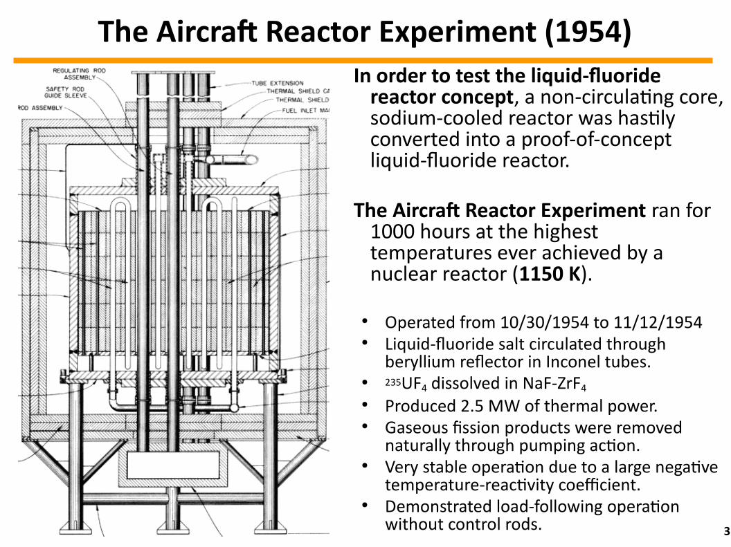
The Aircraft Reactor Experiment (1954)In order to test the liquid-fluoride
reactor concept, a non-circulating core, sodium-cooled reactor was hastily converted into a proof-of-concept liquid-fluoride reactor.
The Aircraft Reactor Experiment ran for 1000 hours at the highest temperatures ever achieved by a nuclear reactor (1150 K).
● Operated from 10/30/1954 to 11/12/1954● Liquid-fluoride salt circulated through
beryllium reflector in Inconel tubes.● 235UF4 dissolved in NaF-ZrF4● Produced 2.5 MW of thermal power.● Gaseous fission products were removed
naturally through pumping action.● Very stable operation due to a large negative
temperature-reactivity coefficient.● Demonstrated load-following operation
without control rods.

4
It wasn’t that I had suddenly become converted to a belief in nuclear airplanes. It was rather that this was the only avenue open to ORNL for continuing in reactor development.
That the purpose was unattainable, if not foolish, was not so important:
A high-temperature reactor could be useful for other purposes even if it never propelled an airplane…
—Alvin Weinberg
Aircraft Nuclear Program Allowed ORNL to Develop Reactors

5
Molten Salt Reactor Experiment (1965-1969)
ORNLs' MSRE: 8 MW(th)Designed 1960 – 1964Started in 1965, 5 years of successful operation
Developed and demonstrated on-line refueling, fluorination to remove uranium UF4+F2→UF6,Vacuum distillation to clean the salt
Operated on all 3 fissile fuels U233, U235, Pu239
Some issues with Hastelloy-Nfound and solved
Further designs suggested (MSBE, MSBR, DMRS), none built
After Alvin Weinberg was removed from ORNL directorate, very little work done, almost no funding The Molten Salt Reactor Adventure, H. G. MacPherson,
Nuclear Science and Engineering 90, p. 374-380 (1985)http://home.earthlink.net/~bhoglund/mSR_Adventure.html

6
Current Predicament
● ORNL's program in the 1960s was predicated on many historical circumstances, which are not valid any more.
● Current political priorities: inherent “walkaway” safety, proliferation resistance, TRU actinide minimization and spent nuclear fuel inventory management, among others.
● Economic necessity: minimization of upfront costs, maximization of resource utilization (see later), and exploring new markets.
● Any futuristic R&D program needs to get actually funded.● Any new reactor R&D and deployment (R&D&D) needs:
● to get regulated using the standard rules tailored to LWR → significant but not insurmountable challenge,
● necessitates new generation of experts in related areas.

7
Salt Selection
● Salts composition differences impacts salt cost, tritium production, and neutronic performance.
● THD differences neglected.

8
Salt/Graphite Lattice
● Parametric scan of neutronics with different salts.● Infinite hexagonal lattice of graphite and salt fuel.● Lattice parameters are channel pitch p and salt fraction f.
● Salt channel radius:
● Reflective unit cell:
r 2 = p2 √32π
f
FUEL SALT GRAPHITE MODERATOR

9
Temperature-Reactivity Feedbacks
● Reactor dynamics is crucial to safety. ● More absorptive salts are problematic in FHRs. MSRs?● Reactivity:
● Temperature-reactivity coefficient needs to be negative.
● Three components to the thermal feedback in MSR:● Doppler – due to resonance broadening: prompt feedback● Salt expansion with temperature: fast feedback● Whole core expansion: slow feedback
● Must investigate finite cores, as changes in leakage may be significant.
ρ =k−1k
d ρ
d T= ?

10
Finite Core Geometry● Our play reactor is a graphite block with holes,
surrounded by 5cm down-comer and 15cm top&bottom plenum, inside a 3cm thick Hastelloy-N tank.
● Graphite block sizes studied: 2x2, 3x3, 5x5, 7x7 meters.● Channel pitch and radius from the lattice searches.
Top view Side view
Graphite
Salt
Tank

11
Calculation Strategy Using MCNP5
● MCNP5 does not broaden the cross-sections on the fly. ● NJOY used to create a special Doppler-broadened cross-
section library for every 50 K step.● Three cases investigated for every salt selection:
a) Doppler effect only – just use a different cross-section library for the fuel salt depending on the temperature.b) Doppler + salt expansion – the above, plus salt density decreased by 10-3 g/cm3 per Kc) Doppler + salt expansion + thermal expansion of the whole reactor – the above, plus physical expansion and temperature changes of the graphite moderator and the tank.– Graphite linear thermal expansion coefficient = 3.5E-6 m/m per K– Hastelloy-N linear thermal expansion coefficient = 15.0E-6 m/m per K

12
Calculation Strategy Using MCNP5 II
● For every salt, two lattice geometries (i.e. the channel pitch p and salt fraction f) are investigated:
1) p and f at max FoM from infinite lattice studies above;2) f at max FoM given p=15cm using the studies above.
● First, find critical uranium enrichment level of the finite core at 900K for every salt and core geometry.
● Then, for each case, re-calculate keff at temperatures T=800K, 850K, 950K, 1000K, and 1100K.
● From keffs, calculate reactivity at every T: ● Fit the reactivity slope as fcn(T) for every case:
ρ(T ) = Td ρ
d T+ c
ρ =k−1k

13
72% 7LiF – 16% BeF2 – 12% UF
4

14
73% 7LiF – 27% UF4

15
78% NaF – 22% UF4

16
49% NaF – 38% ZrF4 – 13% UF
4

17
58% NaF – 30% BeF2 – 12% UF
4

18
74% NaF – 12% BeF2 – 14% UF
4
19
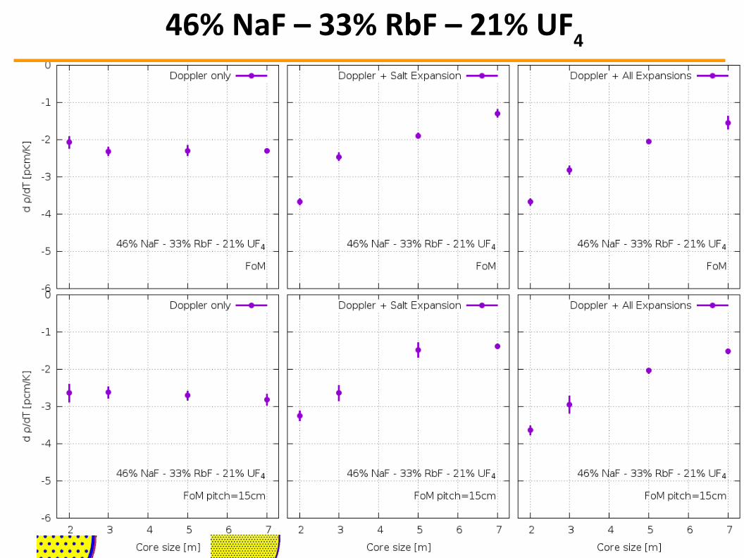
46% NaF – 33% RbF – 21% UF4

20
50.5% NaF – 21.5% KF – 28% UF4

21
Summary: dρ/dT as a function of the core size
● All temperature-reactivity feedbacks are negative for all the cores investigated.
● Doppler feedback depends on the salt choice, independent of the core size.
● Salt thermal expansion enhances feedbacks for small cores (for 3m enhances or is about the same), it reduce feedback for larger cores.
● The effects of whole core (i.e. graphite) thermal expansion adds little to salt expansion feedback, in most cases insignificant enhancement.
● This is surprising since the French group found a large effect from graphite expansion → let us investigate.

22
Isolating the graphite contribution to dρ/dT
● What happens when the core gets hotter?● The salt will be kept at 1100K in all calculations.● The graphite and tank will increase in temperature
(including dimension and density effects) from 800K to 1100K. ● Imagine that the salt heats up by a reactivity insertion, and the
rest of the core starts to warm up consequently.● Then for every core graphite temperature we calculate
reactivity for all salt the selections, core sizes from 2m to 7m , and two different lattice configurations (FoM and FoM15cm).

23
2m x 2m coresFoM FoM p=15cm

24
3m x 3m coresFoM FoM p=15cm

25
5m x 5m coresFoM FoM p=15cm

26
7m x 7m coresFoM FoM p=15cm

27
Future work
● Investigate other moderator geometries, in particular moderating by inert graphite pebbles.
● Temperature-reactivity feed-backs (almost done)→ Check effects of reflectors.
● Double check graphite expansion effects.● Depletion studies for more realistic fuel cycle assessment.
This needs code development for fluid fuels!● Reactor kinetics and dynamics.
This needs more code development for fluid fuels!● …● … ● Build a reactor!
28
Conclusions
● No temperature-reactivity effect seen with graphite expansion for core sizes from 2, to 7m & all salt selections, within (small) statistical errors.
● This contradicts previous research. ● Perhaps graphite density decrease was not accounted for
in the past research?● The data have been posted:
http://web.utk.edu/~ochvala/MSR/
● Thank you for your attention!