basic electrical 1st &2nd sem common th.4(a). basic
TRANSCRIPT

BASIC ELECTRICAL 1ST &2ND SEM COMMON
My channel youtube.com/makeeasyelectricaltechnology | || CHAPTER 01 || 1
Susanta Kumar Sahu(8093349302), Graduated from VSSUT,Burla
Th.4(a). BASIC ELECTRICAL ENGINEERING
(1st sem & 2nd sem Common)
Theory: 2 Periods per Week I.A : 10 Marks
Total Periods: 30 Periods End Sem Exam : 40 Marks
Examination: 1.5 Hours TOTAL MARKS : 50
Marks
Topic wise Distribution of Periods and Marks
Sl.No. Topics Periods
1 Fundamentals 05
2 A C Theory 08
3 Generation of Elect. Power 03
4 Conversion of Electrical
Energy
07
5 Wiring and Power Billing 04
6 Measuring Instrument 03
Total 30
Objective
1. To be familiar with A.C Fundamental and circuits
2. To be familiar with basic principle and application of energy conversion devices
3. To be familiar with generation of Electrical power
4. To be familiar with wiring and protective device
5. To be familiar with calculation and commercial Billing of electrical power & energy
6. To have basic knowledge of various electrical measuring instruments & conservation of
electrical energy
1. FUNDAMENTALS
1.1 Concept of current flow.
1.2 Concept of source and load.
1.3 State Ohm’s law and concept of resistance.
1.4 Relation of V, I & R in series circuit.
1.5 Relation of V, I & R in parallel circuit.
1.6 Division of current in parallel circuit.
1.7 Effect of power in series & parallel circuit.
1.8 Kirchhoff’s Law.
1.9 Simple problems on Kirchhoff’s law.

BASIC ELECTRICAL 1ST &2ND SEM COMMON
My channel youtube.com/makeeasyelectricaltechnology | || CHAPTER 01 || 2
Susanta Kumar Sahu(8093349302), Graduated from VSSUT,Burla
2. A.C. THEORY
2.1 Generation of alternating emf.
2.2 Difference between D.C. & A.C.
2.3 Define Amplitude, instantaneous value, cycle, Time period, frequency, phase angle,
phase difference.
2.4 State & Explain RMS value, Average value, Amplitude factor & Form factor with
Simple problems.
2.5 Represent AC values in phasor diagrams.
2.6 AC through pure resistance, inductance & capacitance
2.7 AC though RL, RC, RLC series circuits.
2.8 Simple problems on RL, RC & RLC series circuits.
2.9 Concept of Power and Power factor
2.10 Impedance triangle and power triangle.
3. GENERATION OF ELECTRICAL POWER
3.1 Give elementary idea on generation of electricity from thermal , hydro & nuclear
power station with block diagram
4. CONVERSION OF ELECTRICAL ENERGY
(No operation, Derivation, numerical problems)
4.1 Introduction of DC machines.
4.2 Main parts of DC machines.
4.3 Classification of DC generator
4.4 Classification of DC motor.
4.5 Uses of different types of DC generators & motors.
4.6 Types and uses of single phase induction motors.
4.7 Concept of Lumen
4.8 Different types of Lamps (Filament, Fluorescent, LED bulb) its Construction and
Principle.
4.9 Star rating of home appliances (Terminology, Energy efficiency, Star rating Concept)
5. WIRING AND POWER BILLING
5.1 Types of wiring for domestic installations.
5.2 Layout of household electrical wiring (single line diagram showing all the important
component in the system).
5.3 List out the basic protective devices used in house hold wiring.
5.4 Calculate energy consumed in a small electrical installation
6. MEASURING INSTRUMENTS
6.1 Introduction to measuring instruments.
6.2 Torques in instruments.
6.3 Different uses of PMMC type of instruments (Ammeter & Voltmeter).
6.4 Different uses of MI type of instruments (Ammeter & Voltmeter).
6.5 Draw the connection diagram of A.C/ D.C Ammeter, voltmeter, energy meter and
wattmeter. (Single phase only).
Syllabus Coverage upto I.A
Chapter 1,2,3

BASIC ELECTRICAL 1ST &2ND SEM COMMON
My channel youtube.com/makeeasyelectricaltechnology | || CHAPTER 01 || 3
Susanta Kumar Sahu(8093349302), Graduated from VSSUT,Burla
BOOKS RECOMENDED:
1. ABC of Electrical Enginnering by Jain & Jain (Dhanpat Rai Publication)
2. Fundamentals of Electrical Engg and Electronics by B.L Thereja
3. Concept of Basic Electrical Enginnering ,P.K Das and A.K. Mallick by B.M Publications
4. Fundamentals of Electrical Engg by Asfaq Hussain
5. Fundamentals of Electrical Engg by JB Gupta
6. Basic Electrical Engg. By Chakraborti (Mcgraw Hill)

BASIC ELECTRICAL 1ST &2ND SEM COMMON
My channel youtube.com/makeeasyelectricaltechnology | || CHAPTER 01 || 4
Susanta Kumar Sahu(8093349302), Graduated from VSSUT,Burla
Contents CHAPTER 01 ............................................................................................................................................ 8
1.0 FUNDAMENTALS ............................................................................................................................... 8
1.1.INTRODUCTION ................................................................................................................................. 8
1.2.Electric charge ................................................................................................................................... 8
1.3.Electric potential and voltage ........................................................................................................... 9
1.4.Electric power ................................................................................................................................. 10
1.5.Electrical Energy .............................................................................................................................. 10
1.5.1Electrical Energy Definition ......................................................................................................... 11
1.5.2Electrical Energy Formula ............................................................................................................ 11
1.5.3Unit of Electrical Energy .............................................................................................................. 11
1.5.4Watt Hours .................................................................................................................................... 11
1.5.5BOT Unit or Board of Trade Unit or Kwh.................................................................................... 11
1.6.Concept of source and load. ........................................................................................................... 11
1.6.1Resistive, Capacitive, Inductive ..................................................................................................... 12
Resistive Load ....................................................................................................................................... 12
Capacitive Load .................................................................................................................................... 12
Inductive Load ...................................................................................................................................... 12
Combination Loads ............................................................................................................................... 12
1.7Ohm's Law: ....................................................................................................................................... 12
1.8Resistance ........................................................................................................................................ 14
1.8.1Resistors in Series ......................................................................................................................... 15
1.9Difference between Series and Parallel circuit ................................................................................ 16
1.9.1Current Divider Rule ..................................................................................................................... 16
General formula .................................................................................................................................... 17
1.10Volage Divider Rule ........................................................................................................................ 20
1.11Kirchhoff’s First & Second Laws ..................................................................................................... 23
1.11.1Kirchhoffs First Law – The Current Law, (KCL) ............................................................................ 23
Kirchhoffs Current Law ........................................................................................................................ 23
1.11.2Kirchhoffs Second Law – The Voltage Law, (KVL) ....................................................................... 24
CHAPTER 02 .......................................................................................................................................... 26
A.C. THEORY .......................................................................................................................................... 26
2.1Generation of Alternating e.m.f....................................................................................................... 26

BASIC ELECTRICAL 1ST &2ND SEM COMMON
My channel youtube.com/makeeasyelectricaltechnology | || CHAPTER 01 || 5
Susanta Kumar Sahu(8093349302), Graduated from VSSUT,Burla
2.2Difference between D.C. & A.C ........................................................................................................ 28
2.3RMS (Root Mean Square)value ........................................................................................................ 30
2.4Mean value or average value of AC................................................................................................. 32
2.5Ac through Resistor Only ................................................................................................................. 34
2.6Ac through inductor only ................................................................................................................. 35
2.7Ac through Capacitor ....................................................................................................................... 37
2.8Ac through resistor and inductor ..................................................................................................... 38
2.9AC through resistor and capacitor ................................................................................................... 40
2.10AC through inductor, capacitor and resistor ................................................................................. 42
2.11Power and Power factor ................................................................................................................ 43
2.12Power Triangle ............................................................................................................................... 45
2.13Impedance Triangle ....................................................................................................................... 45
CHAPTER 03 .......................................................................................................................................... 46
GENERATION OF ELECTRICAL POWER .................................................................................................. 46
3.1Hydro-electric Power Station ........................................................................................................... 46
3.1.1Factors for Selection of Site ........................................................................................................... 46
3.1.2General Arrangement of Hydro-electric Plant .............................................................................. 47
3.1.3Disadvantaes ................................................................................................................................. 50
3.2Steam Power Station ....................................................................................................................... 51
3.2.1General Arrangement of Steam Power Plant ............................................................................... 52
3.2.2Disadvantages ............................................................................................................................... 55
3.4. Efficiency ...................................................................................................................................... 56
3.5Nuclear Power Station ..................................................................................................................... 56
3.5.1General Arrangement of Nuclear Power Plant ............................................................................. 58
3.5.2Nuclear Reactor............................................................................................................................. 60
3.5.2 Heat exchanger ............................................................................................................................. 61
3.5.3 Steam turbine ............................................................................................................................... 61
3.5.4 Alternator ..................................................................................................................................... 61
3.5.5 Cooling Water Circuit .................................................................................................................. 61
3.5.6 Advantages ................................................................................................................................. 61
3.5.7. Disadvantages ............................................................................................................................ 62
CHAPTER 04 .......................................................................................................................................... 63
CONVERSION OF ELECTRICAL ENERGY.................................................................................................. 63
4.1Introduction ..................................................................................................................................... 63
BASIC ELECTRICAL 1ST &2ND SEM COMMON
My channel youtube.com/makeeasyelectricaltechnology | || CHAPTER 01 || 6
Susanta Kumar Sahu(8093349302), Graduated from VSSUT,Burla
4.2Fleming's Right Hnad Rule ............................................................................................................... 63
4.3Fleming's left hand rule ................................................................................................................... 64
4.4Construction (parts) of a Practical D.C. Machine: ............................................................................ 64
4.5Classification of DC Machines: ........................................................................................................ 68
4.6Applications of D.C. Motors ............................................................................................................. 71
4.7Applications of Various Types of Generators .................................................................................. 71
4.8Types of Single Phase Induction Motors .......................................................................................... 71
4.8.1Applications of single phase induction motors ............................................................................. 72
4.9Light: ................................................................................................................................................ 72
4.10Concept of Lumen: ......................................................................................................................... 72
4.11Different types of Lamps: .............................................................................................................. 73
4.11.1Filament(incandescent) bulb ...................................................................................................... 73
4.11.2Fluorescent (Tube) lamp: ............................................................................................................ 73
4.11.3LED Bulb: ..................................................................................................................................... 74
4.12Star rating of home appliances: ..................................................................................................... 74
CHAPTER 05 .......................................................................................................................................... 76
5.1WIRING AND POWER BILLING .......................................................................................................... 76
5.2Different Types of Electrical Wiring Systems ................................................................................... 76
1. Cleat Wiring ....................................................................................................................................... 76
2. Casing and Capping wiring ................................................................................................................ 77
3. Batten Wiring (CTS or TRS)................................................................................................................ 77
4. Lead Sheathed Wiring ....................................................................................................................... 78
5. Conduit Wiring .................................................................................................................................. 78
5.3Layout of household electrical wiring (single line diagram): ........................................................... 79
5.4Basic protective devices used in house hold wiring.:- ..................................................................... 79
5.4.1Fuses ............................................................................................................................................. 79
5.4.2Miniature Circuit Breaker (MCB) .................................................................................................. 80
5.5Energy consumed in a small electrical installation: ......................................................................... 82
5.6Electrical energy Calculation(Power Billing): ................................................................................... 82
CHAPTER 06 .......................................................................................................................................... 83
MEASURING INSTRUMENTS ................................................................................................................. 83
6.1Introduction: .................................................................................................................................... 83
6.2Torques in instruments: ................................................................................................................... 83
6.2.1Deflecting System ......................................................................................................................... 83

BASIC ELECTRICAL 1ST &2ND SEM COMMON
My channel youtube.com/makeeasyelectricaltechnology | || CHAPTER 01 || 7
Susanta Kumar Sahu(8093349302), Graduated from VSSUT,Burla
6.2.2Controlling System ........................................................................................................................ 84
6.2.3Damping System ........................................................................................................................... 84
6.3Permanent Magnet Moving Coil Instruments (PMMC) ................................................................... 84
6.4Moving Iron Instruments ................................................................................................................. 87
6.5Connection diagram of Ammeter, voltmeter: ................................................................................. 88
6.6Connection diagram of wattmeter (single phase): .......................................................................... 88
6.7Connection diagram of Energy meter: ............................................................................................. 89

BASIC ELECTRICAL 1ST &2ND SEM COMMON
My channel youtube.com/makeeasyelectricaltechnology | || CHAPTER 01 || 8
Susanta Kumar Sahu(8093349302), Graduated from VSSUT,Burla
CHAPTER 01
FUNDAMENTALS INTRODUCTION:-
Welcome to this course on Basic Electrical Engineering. Engineering students of almost all
disciplines has to undergo this course (name may be slightly different in different course
curriculum) as a core subject in the first semester. It is needless to mention that how much we
are dependent on electricity in our day to day life.
A reasonable understanding on the basics of applied electricity is therefore important for
every engineer. Apart from learning d.c and a.c circuit analysis both under steady state and
transient conditions, you will learn basic working principles and analysis of transformer, d.c
motors and induction motor. Finally working principles of some popular and useful
indicating measuring instruments are presented.
Electric charge
Electric charge is the physical property of matter that causes it to experience a force when
placed in an electromagnetic field. This force is is directly proportional to the charge
magnitude.
By convention a electron is considered as 1 unit of negative charge and proton as 1 unit of
positive charge.
But in actual flow of electric current or chemical is this electron which participate and not
proton(except in nuclear reaction ). Since electron is -ve, so flow of current is opposite to
flow of electron
Good conductors are generally those which have some free electrons which means. There are
two region called valence band and conduction band. Depending on availability of electron
these energy bands conductivity is determined.
If a conductor gives away some electron, absence of electron is called a hole. Since in general
elements are electrically neutral, after giving up electrons, the overall element is positively
charged.

BASIC ELECTRICAL 1ST &2ND SEM COMMON
My channel youtube.com/makeeasyelectricaltechnology | || CHAPTER 01 || 9
Susanta Kumar Sahu(8093349302), Graduated from VSSUT,Burla
This means a hole may be considered as a positive charge. What happens is this hole
sometimes takes up an electron from a nearest neighbor, creating a hole there. This way the
hole can move which resembles a positive charge moving.
Suppose a man(electron) left a seat(hole) in the bus at the front, you(electron) were standing
at the back end of the bus. Now the nearest person from the next seat move to that empty
seat. So the empty seat will move to the next row. In this way by readjustment from each next
row, the empty seat will reach you .So though holes moves, it is actually the movement of
electron.
unit of electric charge
1 Coulomb = 1 Ampere (times) 1 second. The SI derived unit of electric charge is the
coulomb (C). In electrical engineering, it is also common to use the ampere-hour (Ah), and,
in chemistry, it is common to use the elementary charge (e as a unit). The symbol Q often
denotes charge
Electric potential and voltage
We define voltage as the amount of potential energy between two points on a
circuit. One point has more charge than another. This difference in charge between
the two points is called voltageConsider a water tank at a certain height above the
ground. At the bottom of this tank there is a hose.
When describing voltage, current, and
resistance, a common analogy is a water tank. In this analogy, charge is represented by
the water amount, voltage is represented by the water pressure, and current is
represented by the water flow. So for this analogy,
remember:
Water = Charge
Pressure = Voltage
Flow = Current

BASIC ELECTRICAL 1ST &2ND SEM COMMON
My channel youtube.com/makeeasyelectricaltechnology | || CHAPTER 01 || 10
Susanta Kumar Sahu(8093349302), Graduated from VSSUT,Burla
Unit of Voltage or Electric potential
The voltage between two points is equal to the work done per unit of charge against a
static electric field to move a test charge between two points. This is measured in units of
volts (a joule per coulomb); moving 1 coulomb of charge across 1 volt of electric
potential requires 1 joule of work.
Electric power
Electric power, like mechanical power, is the rate of doing work, measured in watts, and
represented by the letter P. The term wattage is used colloquially to mean "electric power in
watts." The electric power in watts produced by an electric current I consisting of a charge
of Q coulombs every t seconds passing through an electric potential (voltage) difference
of V is
P = work done per unit time= 𝑉𝑄𝑡 =VI
Where
Q is electric charge in coulombs , t is time in seconds , I is electric current in amperes, V is
electric potential or voltage in volts
Electrical Energy
Before explaining what electrical energy is, let us try to review the potential difference
between two points in an electric field.
Suppose potential
difference between point A and point B in an electric is v volts.
As per the definition of potential difference we can say, if one positive unit electrical charge
that is a body containing one-coulomb positive charge travels from point A to point B, it will
do v joules
Work.
BASIC ELECTRICAL 1ST &2ND SEM COMMON
My channel youtube.com/makeeasyelectricaltechnology | || CHAPTER 01 || 11
Susanta Kumar Sahu(8093349302), Graduated from VSSUT,Burla
Now instead of one-coulomb charge if q coulomb charge moves from point A to B, it will do
vq joules work.
Electrical Energy Definition
Electrical energy is the work done by electric charge. If current i ampere flows through a
conductor or through any other conductive element of potential difference v volts across it,
for time t second, the electric energy is,
Electrical Energy Formula
The expression of electric power is The electrical energy is
Unit of Electrical Energy
Basically, we find the unit of electrical energy is joule. This equals to one watt X one second.
Commercially, we also use other units of electrical energy, such as watt-hours, kilo watt
hours, megawatt hours etc.
Watt Hours
If one watt power is being consumed for 1 hour time, the energy consumed is one watt-hour.
BOT Unit or Board of Trade Unit or Kwh The practical, as well as a commercial unit of electrical energy, is kilowatt hour. The
fundamental commercial unit is watt-hour and one kilowatt hour implies 1000 watt hours.
The electrical supply companies take electric energy charges from their consumer per
kilowatt hour unit basis. This kilowatt hour is board of trade unit that is BOT unit.
Concept of source and load. An electrical source, such as a battery or power supply, provides energy in electrical form,
known as current. The maximum power available from such a source is the product of the
maximum current it can supply into a load and the voltage (potential difference) generated
across the load by the current flowing through it. Loads that approach zero resistance will
draw maximum current at a approaching zero voltage (or potential difference).
An electrical load, such as a motor or light bulb, converts electrical energy into some other
form such as motion, light, heat, sound etc. The load is rarely 100% efficient, so usually the
energy is converted into several forms, the largest quantity being the intended conversion (we
hope) the remainder being energy in a different form that may be wasted. For example, an
incandescent light bulb converts electrical energy into light, but not all of the electrical

BASIC ELECTRICAL 1ST &2ND SEM COMMON
My channel youtube.com/makeeasyelectricaltechnology | || CHAPTER 01 || 12
Susanta Kumar Sahu(8093349302), Graduated from VSSUT,Burla
energy is given off as light. Some is radiated as heat, which is considered to be the wasted
proportion.
An electrical load is a device or an electrical component that consumes electrical energy and
convert it into another form of energy. Electric lamps, air conditioners, motors, resistors etc.
are some of the examples of electrical loads. They can be classified according to various
different factors. Some popular classifications of electrical loads are as follows.
Resistive, Capacitive, Inductive
Electrical loads can be classified according to their nature as Resistive, Capacitive, Inductive
and combinations of these.
Resistive Load
Two common examples of resistive loads are incandescent lamps and electric heaters.
Resistive loads consume electrical power in such a manner that the current wave remains
in phase with the voltage wave. That means, power factor for a resistive load is unity.
Capacitive Load
A capacitive load causes the current wave to lead the voltage wave. Thus, power factor
of a capacitive load is leading.
Examples of capacitive loads are: capacitor banks, buried cables, capacitors used in
various circuits such as motor starters etc.
Inductive Load
An inductive load causes the current wave to lag the voltage wave. Thus, power factor of
an inductive load is lagging.
Examples of inductive load include transformers, motors, coils etc.
Combination Loads
Most of the loads are not purely resistive or purely capacitive or purely inductive. Many
practical loads make use of various combinations of resistors, capacitors and inductors.
Power factor of such loads is less than unity and either lagging or leading.
Examples: Single phase motors often use capacitors to aid the motor during starting and
running, tuning circuits or filter circuits etc.
Ohm's Law: Ohm’s law states that at a constant temperature, current 'I' through a conductor between
two points is directly proportional to the potential difference or voltage 'V', across the
two points. That is,

BASIC ELECTRICAL 1ST &2ND SEM COMMON
My channel youtube.com/makeeasyelectricaltechnology | || CHAPTER 01 || 13
Susanta Kumar Sahu(8093349302), Graduated from VSSUT,Burla
Thus, the ratio V : I is a constant. This constant is called as the resistance (R) of the
conductor.
Graph:
After performing experiment for different readings of V & I and recording the
observations, if we plot current on the x-axis of a graph and voltage on the y-axis of the
graph, we will get a straight-line. The gradient of the straight-line graph is related to the
resistance (R) of the conductor.

BASIC ELECTRICAL 1ST &2ND SEM COMMON
My channel youtube.com/makeeasyelectricaltechnology | || CHAPTER 01 || 14
Susanta Kumar Sahu(8093349302), Graduated from VSSUT,Burla
Resistance

BASIC ELECTRICAL 1ST &2ND SEM COMMON
My channel youtube.com/makeeasyelectricaltechnology | || CHAPTER 01 || 15
Susanta Kumar Sahu(8093349302), Graduated from VSSUT,Burla
Resistors in Series
Resistors in Parallel

BASIC ELECTRICAL 1ST &2ND SEM COMMON
My channel youtube.com/makeeasyelectricaltechnology | || CHAPTER 01 || 16
Susanta Kumar Sahu(8093349302), Graduated from VSSUT,Burla
Difference between Series and Parallel circuit. Sl no. Parameters Series circuit Parallel circuit
1 Current The current is the same in
all
parts of the circuit
The total current supplied to the
network equals the sum of the
currents in the various branches
2 Voltage The total voltage equals
the
sum of the voltages across
the
different parts of the
circuit
The voltage across a parallel
combination is the same as the
voltage across each branch
3 Resistance The total resistance equals
the sum of the separate
resistances
R= 𝑅1 + 𝑅2 + 𝑅3 …. The reciprocal of the equivalent
resistance equals the sum of the
reciprocals of the branch
resistances
R=1𝑅1 + 1𝑅2 + 1𝑅3 + ⋯
Current Divider Rule
In parallel electrical circuits, the current doesn't remain same. The current divide rule is used
to find the divided current in parallel circuits
Statement: The electrical current entering the node of a parallel circuit is divided into the
branches. Current divider formula is employed to calculate the magnitude of divided
current in the circuits.
Let's understand the basic definitions:
Node: A point where two or more than two components are joined.
Parallel circuit: The circuit in which one end of all components share a common node, and
the other end of all components share the other common node.

BASIC ELECTRICAL 1ST &2ND SEM COMMON
My channel youtube.com/makeeasyelectricaltechnology | || CHAPTER 01 || 17
Susanta Kumar Sahu(8093349302), Graduated from VSSUT,Burla
General formula
A parallel circuit with 'n' number of resistors and an input voltage source is illustrated below.
We are interested to find the current which is flowing through Rx.
In the above formula:
Ix: The current through Rx.
It: The total current which enters the circuit.
Rx: The resistance of the component whose current value is to be determined
Rt: The equivalent resistance of the parallel circuit
For two resistors
Let's consider a parallel circuit having two resistors R1 and R2. The current It enters the node.
We are interested to calculate the current that is flowing through. The general formula and
circuit now take the form:

BASIC ELECTRICAL 1ST &2ND SEM COMMON
My channel youtube.com/makeeasyelectricaltechnology | || CHAPTER 01 || 18
Susanta Kumar Sahu(8093349302), Graduated from VSSUT,Burla
We can modify the previous equation to obtain an alternative formula:
Let's solve an example to better understand the formulas.
BASIC ELECTRICAL 1ST &2ND SEM COMMON
My channel youtube.com/makeeasyelectricaltechnology | || CHAPTER 01 || 19
Susanta Kumar Sahu(8093349302), Graduated from VSSUT,Burla
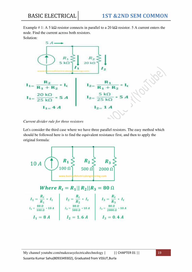
Example # 1: A 5 kΩ resistor connects in parallel to a 20 kΩ resistor. 5 A current enters the
node. Find the current across both resistors.
Solution:
Current divider rule for three resistors
Let's consider the third case where we have three parallel resistors. The easy method which
should be followed here is to find the equivalent resistance first, and then to apply the
original formula:

BASIC ELECTRICAL 1ST &2ND SEM COMMON
My channel youtube.com/makeeasyelectricaltechnology | || CHAPTER 01 || 20
Susanta Kumar Sahu(8093349302), Graduated from VSSUT,Burla
Volage Divider Rule
The electrical current always remains same in the series components. However, the voltage
doesn't remain same in series components. The voltage divider rule is used to find the voltage
divided across different components
The magnitude of divided voltage in a series circuit depends on the magnitude of
resistance.
A series circuit is the one where one end of component connects to other and there is no other
component in between them.
General formula
The general formula for calculating the voltage divider in a series circuit with 'n' resistors is:
Let's simplify the general formula for two resistors.
The circuit below displays a circuit with two resistors R1 and R2. The source Vin powers
circuit.
BASIC ELECTRICAL 1ST &2ND SEM COMMON
My channel youtube.com/makeeasyelectricaltechnology | || CHAPTER 01 || 21
Susanta Kumar Sahu(8093349302), Graduated from VSSUT,Burla
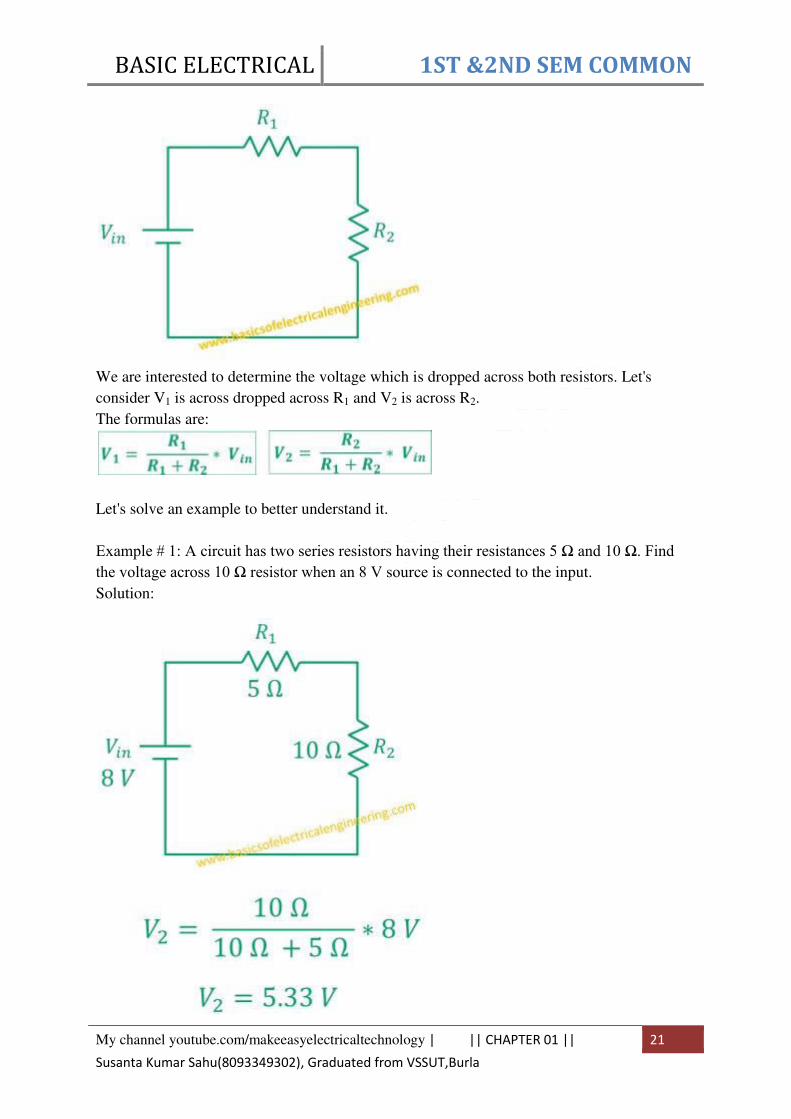
We are interested to determine the voltage which is dropped across both resistors. Let's
consider V1 is across dropped across R1 and V2 is across R2.
The formulas are:
Let's solve an example to better understand it.
Example # 1: A circuit has two series resistors having their resistances 5 Ω and 10 Ω. Find the voltage across 10 Ω resistor when an 8 V source is connected to the input.
Solution:

BASIC ELECTRICAL 1ST &2ND SEM COMMON
My channel youtube.com/makeeasyelectricaltechnology | || CHAPTER 01 || 22
Susanta Kumar Sahu(8093349302), Graduated from VSSUT,Burla
In the similar fashion, we can apply the voltage divider rule to three, four, five or any number
of resistors. The formula to calculate voltage V1, V2, and V3 across R1, R2, and
R3 respectively is:
Example # 2: Three resistors of 5, 10, 15 Ω are joined in series to 20 V source. Find the current across R3.
Solution:

BASIC ELECTRICAL 1ST &2ND SEM COMMON
My channel youtube.com/makeeasyelectricaltechnology | || CHAPTER 01 || 23
Susanta Kumar Sahu(8093349302), Graduated from VSSUT,Burla
Kirchhoff’s First & Second Laws In 1845, a German physicist, Gustav Kirchhoff developed a pair or set of rules or laws
which deal with the conservation of current and energy within electrical circuits. These two
rules are commonly known as: Kirchhoffs Circuit Laws with one of Kirchhoffs laws dealing
with the current flowing around a closed circuit, Kirchhoffs Current Law, (KCL)while the
other law deals with the voltage sources present in a closed circuit, Kirchhoffs Voltage Law,
(KVL).
Kirchhoffs First Law – The Current Law, (KCL)
Kirchhoffs Current Law or KCL, states that the “total current or charge entering a junction
or node is exactly equal to the charge leaving the node as it has no other place to go except
to leave, as no charge is lost within the node“. In other words the algebraic sum of ALL the
currents entering and leaving a node must be equal to zero, I(exiting) + I(entering) = 0. This idea by
Kirchhoff is commonly known as the Conservation of Charge.
Kirchhoffs Current Law
Here, the three currents entering the node, I1, I2, I3 are all positive in value and the two
currents leaving the node, I4 and I5 are negative in value. Then this means we can also rewrite
the equation as;
I1 + I2 + I3 – I4 – I5 = 0
The term Node in an electrical circuit generally refers to a connection or junction of two or
more current carrying paths or elements such as cables and components. Also for current to
flow either in or out of a node a closed circuit path must exist. We can use Kirchhoff’s
current law when analysing parallel circuits.

BASIC ELECTRICAL 1ST &2ND SEM COMMON
My channel youtube.com/makeeasyelectricaltechnology | || CHAPTER 01 || 24
Susanta Kumar Sahu(8093349302), Graduated from VSSUT,Burla
Example: Find the current through a 20Ω resistance, and current through a 40Ω resistance.
Write KCL at node x
Write in the circuit using Ohm’s Law
Apply last two equation into KCL at node x
The current through a 20Ω resistance
The current through a 40Ω resistance
Kirchhoffs Second Law – The Voltage Law, (KVL)
Kirchhoffs Voltage Law or KVL, states that “in any closed loop network, the total voltage
around the loop is equal to the sum of all the voltage drops within the same loop” which is
also equal to zero. In other words the algebraic sum of all voltages within the loop must be
equal to zero. This idea by Kirchhoff is known as the Conservation of Energy
Kirchhoff’s Voltage Law (KVL):
The algebraic sum of all voltage around the closed loop must be always zero.
1. if the positive (+) side of the voltage is encountered first, assign a positive “+”sign to the
voltage across the element.
2. If the negative (-) side of the voltage is encountered first, assign a negative “-”sign to the
voltage across the element.

BASIC ELECTRICAL 1ST &2ND SEM COMMON
My channel youtube.com/makeeasyelectricaltechnology | || CHAPTER 01 || 25
Susanta Kumar Sahu(8093349302), Graduated from VSSUT,Burla
For the following figure
To use KVL to analyze a circuit,
1. Write KVL equations for voltages
2. Use Ohm’s law to write voltages in terms of resistances and currents.
Solve to find values of the currents and then voltages.
Example : Find the current i and voltage v over the each resistor.
KVL equations for voltages

BASIC ELECTRICAL 1ST &2ND SEM COMMON
My channel youtube.com/makeeasyelectricaltechnology | || CHAPTER 02 || 26
Susanta Kumar Sahu(8093349302), Graduated from VSSUT,Burla
Using Ohm’s Law
Substituting into KVL equation
CHAPTER 02
A.C. THEORY
Generation of Alternating e.m.f.
We know that an alternating e.m.f. can be generated either by rotating a coil within stationary
magnetic field or by rotating a magnetic field within a stationary coil. The magnitude of
e.m.f. generated in the coil depends upon the number of turns on coil, strength of magnetic
field and the speed at which the coil or magnetic field rotates.
Consider a coil of N turns rotating with angular velocity ω radians per second in a uniform magnetic field, as shown it.
Let the time be measured from the instant of coincidence of the plane of the instant of
coincidence of the plane of the coil with the X-axis. At this instant maximum flux, φmax links
with the coil. Let the coil assume the position as shown in after moving in counter clock wise

BASIC ELECTRICAL 1ST &2ND SEM COMMON
My channel youtube.com/makeeasyelectricaltechnology | || CHAPTER 02 || 27
Susanta Kumar Sahu(8093349302), Graduated from VSSUT,Burla
direction for t seconds.
The angle θ through which the coil has rotated in t seconds = ωt
In this position, the component of flux along perpendicular to the plane of coil = φmax cos ωt
Hence flux linkage of the coil at this instant = Number of turns on coil x linking flux =
φmax cos ωt
i.e. instantaneous flux linkage = N φmax cos ωt
Since e.m.f. induced in a coil equal to the rate of change of flux linkage with minus sing.
so e.m.f. induced at any instant, e = - d/ dt [ N φmax cos ]
= φmax N d ( - cos ωt ) = φmax Nω sin ωt dt
when ωt = 0, sin ωt = 0
therefore, induced e.m.f. is zero, when ωt = π/2 , sin π /2 = 1,
therefore induced e.m.f is maximum, which s denoted by Emax and is equal to Nω.
Substituting, φ max Nω = Emax
Instantaneous e.m.f. e = Emax sin ωt
So the e.m.f. induced varies as the since function f the time angle ωt and if e.m.f. induced is plotted against time, a curve of sine wave shape is obtained, as shown in . Such an e.m.f. is
called the sinusoidal e.m.f. The since curve is completed when the coil moves through an

BASIC ELECTRICAL 1ST &2ND SEM COMMON
My channel youtube.com/makeeasyelectricaltechnology | || CHAPTER 02 || 28
Susanta Kumar Sahu(8093349302), Graduated from VSSUT,Burla
angel of 2π radians.
Difference between D.C. & A.C.
Basis Alternating current(A.C) Direct current(D.C)
Definition The direction of the current
reverse periodically.
The direction of the
current remain same.
Causes of flow of
electrons
Rotating a coil in a uniform
magnetic field or rotating a
uniform magnetic field within
a stationary coil
Constant magnetic field
across the wire
Frequency 50 or 60 Hertz Zero
Direction of flow
of electrons.
Bidirectional Unidirectional
Power Factor Lies between 0 and 1 Always 1
Polarity It has polarity (+, -) Do not have polarity
Obtained From Alternators Generators, battery,
solar cell, etc.
Type of load Their load is resistive,
inductive or capacitive.
Their load is usually
resistive in nature.
Graphical
Representation
It is represented by irregular
waves like triangular wave,
square wave, square tooth
wave, sine wave.
It is represented by the
straight line.
Transmission Can be transmitted over long
distance with some losses.
It can be transmitted
over very long distance
with negligible losses.
Convertible Easily convert into direct
current
Easily convert into
alternating current
Substation Few substation is required for More substations are

BASIC ELECTRICAL 1ST &2ND SEM COMMON
My channel youtube.com/makeeasyelectricaltechnology | || CHAPTER 02 || 29
Susanta Kumar Sahu(8093349302), Graduated from VSSUT,Burla
Basis Alternating current(A.C) Direct current(D.C)
generation and transmission required for generation
and transmission
Passive
Parameter
Impedance Resistance
Harazdous Dangerous Very dangerous
Application Factories, Industries and for
the domestic purposes.
Electroplating,
Electrolysis, Electronic
Equipment etc.
Some Important terms and Defination:
Waveform
The shape of the curve of the voltage or current when plotted against time as abscissa (base)
is called the waveform. The waveform of an alternating voltage varying sinusoidal is shown
in Fig. 1. The waveform of the induced emf in an alternator differs slightly from that of sine
wave but for calculation purposes it is treated as such.

BASIC ELECTRICAL 1ST &2ND SEM COMMON
My channel youtube.com/makeeasyelectricaltechnology | || CHAPTER 02 || 30
Susanta Kumar Sahu(8093349302), Graduated from VSSUT,Burla
Alternation and Cycle.
When a periodic wave, such as sinusoidal wave, goes through one complete set of positive or
negative values, it completes one alternation and when it goes through one complete set of
positive and negative values it is said to have completed one cycle.
Alternation and cycle can also be defined in terms of angular measure. One alternation
corresponds to 180° (or radians) while one cycle corresponds to 360° (or radians).
Time Period and Frequency.
The time taken in seconds by an alternating quantity to complete one cycle is known as time
period or periodic time and is denoted by T.
The number of cycles completed per second by an alternating quantity is known as
frequency,and is denoted by f. In SI system, the frequency is expressed in hertz (pronounced
as hurts). One hertz (or Hz)
Time period, T = Time taken in completing one cycle = 1/f, sec
The commercial ac power is generated at frequency of 50 Hz or 60 Hz.
Amplitude.
The maximum value, positive or negative, which an alternating quantity attains during one
cycle is called the amplitude of the alternating quantity. The amplitude of an alternating emf
(or Voltage) and current is designated by Emax (or Vmax) and Imax respectively.
Instantaneous value.
The value of alternating quantity (emf, voltage or current) at any particular instant is called
the instantaneous value and is designated by a small italic letter (e for emf, v for voltage
and i for current). The instantaneous values of an alternating quantity can be determined
either from the curve or from an equation of the alternating quantity. For example, the
instantaneous values of emf represented by the curve shown in Fig. 1 at
0, π/2, and 3π/2 are zero, +Emax, zero and -Emax respectively.
RMS (Root Mean Square)value:
The r.m.s. value of an alternating current is given by that steady (d.c.) current which when
flowing through a given circuit for a given time produces the same heat as produced by the
alternating current when flowing through the same circuit for the same time.
To calculate the mean value of ac, Let us consider an ac given by
the small amount of work done by an ac in small time dt is
So total work done is obtained by integrating equation ii from t = 0 to t = T we get

BASIC ELECTRICAL 1ST &2ND SEM COMMON
My channel youtube.com/makeeasyelectricaltechnology | || CHAPTER 02 || 31
Susanta Kumar Sahu(8093349302), Graduated from VSSUT,Burla
If Irms be the RMS value of ac then it would do the same work as in equation iii while passing
through R in time T
Now from equation iii and iv we get
This relation shows that the root mean square value of ac is about 70.7% of its pick value.
Similarly the root mean square value of alternating emf is

BASIC ELECTRICAL 1ST &2ND SEM COMMON
My channel youtube.com/makeeasyelectricaltechnology | || Mean value or average
value of AC ||
32
Susanta Kumar Sahu(8093349302), Graduated from VSSUT,Burla
Mean value or average value of AC
The mean value or average value of AC over a complete cycle is zero. So we do not consider
the average value of AC over one cycle. We therefore take the average value of AC over a
half cycle only I.e. from t=0 to t=T/2
The average value of AC over a half cycle is that value of steady current that would send
same amount of charge in same interval of time that would be sent by the DC in same time.
To calculate the mean value of ac, Let us consider an ac given by
the small amount of charge sent by an ac in small time dt is
total charge carried by ac in half cycle is obtained by integrating equation ii from t = 0 to t =
T/2

BASIC ELECTRICAL 1ST &2ND SEM COMMON
My channel youtube.com/makeeasyelectricaltechnology | || Mean value or average
value of AC ||
33
Susanta Kumar Sahu(8093349302), Graduated from VSSUT,Burla
If Im be the average ac then charge carried by it in half cycle is
Now from equation iii and iv we get
BASIC ELECTRICAL 1ST &2ND SEM COMMON
My channel youtube.com/makeeasyelectricaltechnology | || Mean value or average
value of AC ||
34
Susanta Kumar Sahu(8093349302), Graduated from VSSUT,Burla
Similarly the average value of ac over negative half cycle (t = T/2 to t = T) is
Therefore the average ac over a complete cycle is zero.
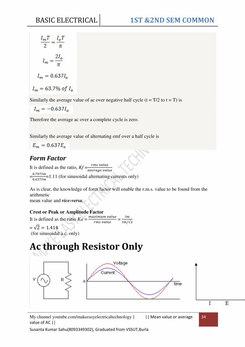
Similarly the average value of alternating emf over a half cycle is
Form Factor
It is defined as the ratio, Kf =𝑟𝑚𝑠 𝑣𝑎𝑙𝑢𝑒𝑎𝑣𝑒𝑟𝑎𝑔𝑒 𝑣𝑎𝑙𝑢𝑒
=0.707𝐼𝑚0.637𝐼𝑚=1.11 (for sinusoidal alternating currents only)
As is clear, the knowledge of form factor will enable the r.m.s. value to be found from the
arithmetic
mean value and vice-versa.
Crest or Peak or Amplitude Factor
It is defined as the ratio Ka = 𝑚𝑎𝑥𝑖𝑚𝑢𝑚 𝑣𝑎𝑙𝑢𝑒𝑟𝑚𝑠 𝑣𝑎𝑙𝑢𝑒 =
𝐼𝑚𝐼𝑚/√2
= √2 = 1.414
(for sinusoidal a.c. only)
Ac through Resistor Only

BASIC ELECTRICAL 1ST &2ND SEM COMMON
My channel youtube.com/makeeasyelectricaltechnology | || Mean value or average
value of AC ||
35
Susanta Kumar Sahu(8093349302), Graduated from VSSUT,Burla
Let an alternating emf be applied to a circuit containing resistor R only such type of circuit is
called resistive circuit.
Let the emf applied to the circuit is
Let I be the current in the circuit then potential difference across the resistor is
Comparing
with ohm’s law, we see that current is equal to voltage/resistance
This means the resistance R is resistance for ac which is in fact the resistance for dc.
Therefore the behavior of R is same for ac and dc.
Ac through inductor only
Let an alternating emf be applied to a circuit containing inductor only such type of circuit is
called inductive circuit.
Let the emf applied to the circuit is

BASIC ELECTRICAL 1ST &2ND SEM COMMON
My channel youtube.com/makeeasyelectricaltechnology | || Mean value or average
value of AC ||
36
Susanta Kumar Sahu(8093349302), Graduated from VSSUT,Burla
then the induced emf across the inductor is
This emf opposes the growth of current in the circuit.
Applying kirchhoff’s voltage law in the loop of fig a
integrating above expression we get
This is the form of alternating current developed in the purely inductive circuit. equation i
and ii shows that in a purely inductive circuit alternating emf leads the alternating current by
π/2

BASIC ELECTRICAL 1ST &2ND SEM COMMON
My channel youtube.com/makeeasyelectricaltechnology | || Mean value or average
value of AC ||
37
Susanta Kumar Sahu(8093349302), Graduated from VSSUT,Burla
Ac through Capacitor
Let an alternating emf be applied to a circuit containing capacitor only such type of circuit is
called capacitive circuit.
Let the emf applied to the circuit is
Let q be the charge in the capacitor of capacitance C then the potential developed in the
capacitor is
Equation ii is the type of current developed in the purely capacitive circuit.
Comparing equation i and ii we see that the alternating current leads to the alternating emf by
π/2 as shown in fig.

BASIC ELECTRICAL 1ST &2ND SEM COMMON
My channel youtube.com/makeeasyelectricaltechnology | || Mean value or average
value of AC ||
38
Susanta Kumar Sahu(8093349302), Graduated from VSSUT,Burla
Ac through resistor and inductor
Let a pure inductance and a pure resistance be connected in series to an alternating emf. Let
Ebe the rms value of applied emf and I be the rms value of the current flowing in the circuit.
Let VR and VL be the potential drop across R and L respectively.
The potential drop across inductor is
The potential drop across resistance is
Since the potential leads the current by π/2 phase in inductive circuit so the potential has been represented by OB at π/2 of OA
Since the potential and the current are in the same phase in case of resistive circuit so they
have been represented by the same line OA.
From the fig the resultant OH is given by

BASIC ELECTRICAL 1ST &2ND SEM COMMON
My channel youtube.com/makeeasyelectricaltechnology | || Mean value or average
value of AC ||
39
Susanta Kumar Sahu(8093349302), Graduated from VSSUT,Burla
This is the effective opposition offered by LR circuit for the flow of current.
Also
This shows that the potential leads the current by π/2 in LR circuit.
Since the potential lags the current by π/2 phase in case of capacitor circuit so the potential has been represented by OA at π/2 of OB
Since the potential and the current are in the same phase in case of resistive circuit so they
have been represented by the same line OB.

BASIC ELECTRICAL 1ST &2ND SEM COMMON
My channel youtube.com/makeeasyelectricaltechnology | || Mean value or average
value of AC ||
40
Susanta Kumar Sahu(8093349302), Graduated from VSSUT,Burla
AC through resistor and capacitor
Let a pure resistor and a pure capacitor be connected in series to an alternating emf. Let E be
the rms value of applied emf and I be the rms value of the current flowing in the circuit. Let
VR and VC be the potential drop across R and C respectively.
The potential drop across capacitor is
The potential drop across resistance is
From the fig the resultant OH is given by

BASIC ELECTRICAL 1ST &2ND SEM COMMON
My channel youtube.com/makeeasyelectricaltechnology | || Mean value or average
value of AC ||
41
Susanta Kumar Sahu(8093349302), Graduated from VSSUT,Burla
This is the effective opposition offered by RC circuit for the flow of current.
Also
This shows that the potential lags the current by π/2 in RC circuit.
BASIC ELECTRICAL 1ST &2ND SEM COMMON
My channel youtube.com/makeeasyelectricaltechnology | || Mean value or average
value of AC ||
42
Susanta Kumar Sahu(8093349302), Graduated from VSSUT,Burla
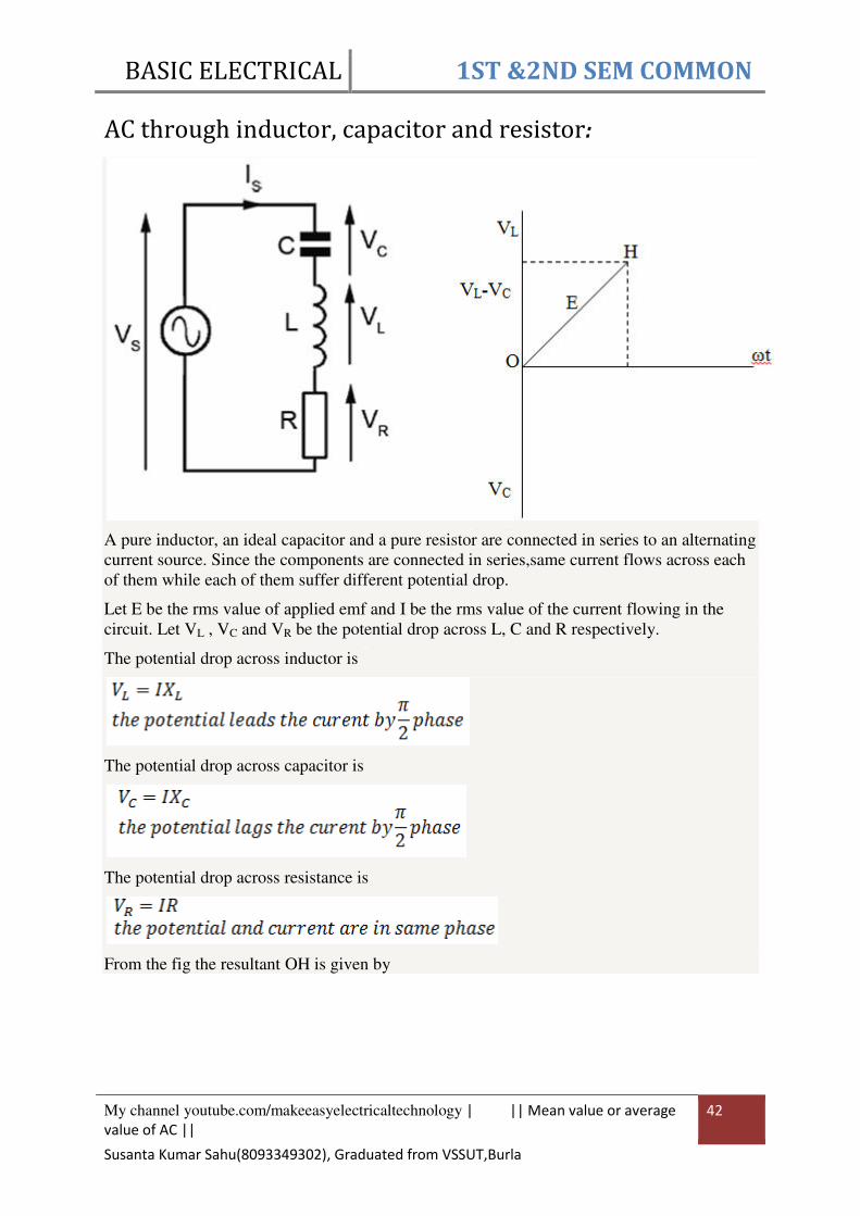
AC through inductor, capacitor and resistor:
A pure inductor, an ideal capacitor and a pure resistor are connected in series to an alternating
current source. Since the components are connected in series,same current flows across each
of them while each of them suffer different potential drop.
Let E be the rms value of applied emf and I be the rms value of the current flowing in the
circuit. Let VL , VC and VR be the potential drop across L, C and R respectively.
The potential drop across inductor is
The potential drop across capacitor is
The potential drop across resistance is
From the fig the resultant OH is given by

BASIC ELECTRICAL 1ST &2ND SEM COMMON
My channel youtube.com/makeeasyelectricaltechnology | || Mean value or average
value of AC ||
43
Susanta Kumar Sahu(8093349302), Graduated from VSSUT,Burla
This is the3 impedance of LCR circuit. It is the effective opposition offered by LCR circuit
for the flow of current.
Also
Power and Power factor
Real Power: (P)
Alternative words used for Real Power (Actual Power, True Power, Watt-full Power, Useful
Power, Real Power, and Active Power)
BASIC ELECTRICAL 1ST &2ND SEM COMMON
My channel youtube.com/makeeasyelectricaltechnology | || Mean value or average
value of AC ||
44
Susanta Kumar Sahu(8093349302), Graduated from VSSUT,Burla
In a DC Circuit, power supply to the DC load is simply the product of Voltage across the load
and Current flowing through it i.e., P = V I. because in DC Circuits, there is no concept of
phase angle between current and voltage. In other words, there is no Power factor in DC
Circuits.
But the situation is Sinusoidal or AC Circuits is more complex because of phase difference
between Current and Voltage.
Therefore average value of power (Real Power) is P = VI Cosθ is in fact supplied to the
load.
Reactive Power: (Q)
Also known as (Use-less Power, Watt less Power)
The powers that continuously bounce back and forth between source and load is known as
reactive Power (Q) Power merely absorbed and returned in load due to its reactive properties
is referred to as reactive power. The unit of Active or Real power is Watt where 1W = 1V x 1
A. Reactive power represent that the energy is first stored and then released in the form of
magnetic field or electrostatic field in case of inductor and capacitor respectively.
Reactive power is given by Q = V I Sinθ which can be positive (+ve) for inductive, negative
(-Ve) for capacitive load.
The unit of reactive power is Volt-Ampere reactive. I.e. VAR where 1 VAR = 1V x 1A. In
more simple words, in Inductor or Capacitor, how much magnetic or electric field made by
1A x 1V is called the unit of reactive power.
Apparent Power: (S)
The product of voltage and current if and only if the phase angle differences between current
and voltage are ignored. Total power in an AC circuit, both dissipated and absorbed/returned
is referred to as apparent power The combination of reactive power and true power is called
apparent power
In an AC circuit, the product of the r.m.s voltage and the r.m.s current is called apparent
power. It is the product of Voltage and Current without phase angle The unit of Apparent
power (S) VA i.e. 1VA = 1V x 1A. When the circuit is pure resistive, then apparent power is
equal to real or true power, but in inductive or capacitive circuit, (when Reactances exist)
then apparent power is greater than real or true power. S = V I

BASIC ELECTRICAL 1ST &2ND SEM COMMON
My channel youtube.com/makeeasyelectricaltechnology | || Mean value or average
value of AC ||
45
Susanta Kumar Sahu(8093349302), Graduated from VSSUT,Burla
Power Triangle
Power factor, cos(θ) , cosine angle between voltage and current
cos(θ)= 𝑃(𝐴𝑐𝑡𝑖𝑣𝑒 𝑃𝑜𝑤𝑒𝑟)𝑆(𝐴𝑝𝑝𝑎𝑟𝑎𝑛𝑡 𝑃𝑜𝑤𝑒𝑟), unit less
Impedance Triangle
Where R=Resistance in Ohm, XL=Inductive Reactance in Ohm
Xc=Capacitive Reactance in ohm
Power factor, cos(θ) , cosine angle between voltage and current
cos(θ)= 𝑅𝑍, unit less

BASIC ELECTRICAL 1ST &2ND SEM COMMON
My channel youtube.com/makeeasyelectricaltechnology | || CHAPTER 03 || 46
Susanta Kumar Sahu(8093349302), Graduated from VSSUT,Burla
CHAPTER 03
GENERATION OF ELECTRICAL POWER
Hydro-electric Power Station
A power generation station which uses the potential or kinetic energy of water for the
generation of an electrical energy is called hydro-electric power station.
Water has a kinetic energy when it is in motion. While the water stored at high level has
a potential energy. The difference in level of water between the two points is called head.
Such a water head is practically created by constructing reservoirs across river or lake.
Generally a dam is constructed at high altitudes, which can be used as a continuous source of
the water for the hydro-electric power stations. The water from the dam is taken through
pipes and canals to the water turbine, which is at lower level. The turbine obtains the energy
from the falling water and changes it into a mechanical energy. This mechanical energy of the
turbine is then used to drive the alternator, which converts the mechanical energy into an
electrical energy. The energy conversion involved in hydro-electric power generation is
shown in the Fig. 1.
Fig.3. 1 Energy conversion
3.1.Factors for Selection of Site
The water reservoir like dam can not be constructed anywhere. There are number of
factors of affecting the choice of site for the hydroelectric power station.
1. Availability of water : As the basic requirement of hydro-electric plant is the water, the
availability of huge quantity of water is the main consideration. The plant must be
constructed where sufficient quantity of water is available at a good head. The previous
rainfall records are studied and the maximum and minimum quantity of water available
during the year estimated. Considering the losses such as evaporation, the water necessary for
the plant is calculated. Then by comparing both the estimations, the choice of the site is done.

BASIC ELECTRICAL 1ST &2ND SEM COMMON
My channel youtube.com/makeeasyelectricaltechnology | || GENERATION OF
ELECTRICAL POWER ||
47
Susanta Kumar Sahu(8093349302), Graduated from VSSUT,Burla
2. Storage of water : The rainfall is not consistent every year. Hence the available water
should be stored. This makes necessary to construct dams. The storage helps in equalizing the
flow of water throughout the year. So site should be provide sufficient facilities for erecting
dam and the storage of water.
3. Head of water : For getting sufficient head, the dam or reservoir should be constructed at
a height in a hilly area. The availability of the head directly affects the cost and economy of
the power generation. So site should be selected in proper geographical area, which can give
sufficient water head.
4. Cost and type of land : The initial cost of the project includes the cost of the land. Hence
land must be available at a reasonable price. Similarly the type of the land must be such that
it should able to withstand the weight of the heavy equipments to be installed.
5. Transportation facilities : For transporting the equipments and the machinery, the site
selected must be easily accessible by rail and road.
6. Distance from load centers : The load center is connected to the site by the transmission
lines. Hence to keep the cost of the transmission lines minimum and the losses occurring in
the line minimum, the distance of the site from the load centers must be less. Otherwise the
overall cost increases considerably.
All these factors affect the selection of site for the hydro-electric power station.
General Arrangement of Hydro-electric Plant
Though hydro-electric power station simply involves the conversion of hydraulic energy
to the mechanical energy, it requires many types of supporting arrangements. The Fig. 2
shows the schematic arrangement of hydro-electric power station which uses water supply
from an artificially constructed dam.

BASIC ELECTRICAL 1ST &2ND SEM COMMON
My channel youtube.com/makeeasyelectricaltechnology | || GENERATION OF
ELECTRICAL POWER ||
48
Susanta Kumar Sahu(8093349302), Graduated from VSSUT,Burla
Fig. 3.2 Schematic arrangement of hydro-electric power plant
The dam is constructed across the river and water from catchment area is collected
behind the wall of the dam, in high mountains. A pressure channel is taken from such a water
reservoir which takes water to a surge tank. The surge tank is a controlling room which
controls the flow of water i.e. adjusts the discharge of water according to the need of the
turbine and load on it. Trash rack does not allow floating and other impurities to pass to the
turbine. The pressure channels plays a very important role. It relieves the pressure on the
penstocks when the turbine valves are open or closed suddenly. The water is then taken to a
valve house from where the penstocks start. The valve house contains main sluice valve and
the automatic isolating valves. These valves also regulate the flow of water to the power
house and isolates the supply of water if there is any emergency such as bursting of a
penstock. Through the penstocks, the water is taken to the power house which consists of
turbine and the alternator. The penstock are nothing but the steel pipes which are arranged in
the form of open or closed conduits, supported by the anchor blocks.
When the water from the penstock is hammered through a nozzle, on the turbine blades,
the turbine starts rotating. At this stage the hydraulic energy is converted to a mechanical
energy. The turbine drives the alternator which is coupled to the shaft of the turbine. The
alternator converts the mechanical energy into an electrical energy. This electrical energy is
then transmitted to the load centers. The water collected from the turbine is called tail race.
This tail race is then taken off to the river.
3.2. Constituents of Hydro-electric Power Station
Let us discuss the constituent and their functions in the operation of the hydroelectric
power station.
Dam
The water reservoir in the form of a dam is the main part of the power station. It stores
the water, provides the continuous supply of water and maintains the necessary water head.
The dams are built up of stones and concrete. The design and type of the dam us selected
according to the topography of the site and economical aspects.
Spillways
There are certain times when the river flow exceeds the storage capacity of the dam, due
to the heavy rainfall. The spillways are provided to discharge this surplus water and maintain
safe water level in the dam.
Surge Tank
This is an important projecting device in a hydro-electric power plant. It is built just
before the valve house. It protects the penstocks from bursting due to sudden pressure
changes.
If the load on the turbine is thrown off suddenly then by the governing action, the turbine
input gates get suddenly closed. Thus there is sudden stopping of water at the lower end of
the penstock. This time the excess water at the lower end of the penstock, rushes back to the
surge tank. The surge tank water level increases. Thus the penstock is protected from bursting
due to high pressure. The surge tank absorbs this high pressure swing by increasing its water
level.

BASIC ELECTRICAL 1ST &2ND SEM COMMON
My channel youtube.com/makeeasyelectricaltechnology | || GENERATION OF
ELECTRICAL POWER ||
49
Susanta Kumar Sahu(8093349302), Graduated from VSSUT,Burla
On the other hand, when the load on the turbine suddenly increases, the additional water
required is drawn from the surge tank. This satisfies the increased water demand instantly.
Thus the surge tank controls the pressure changes created due to rapid changes in the
water flow in penstock and hence protects the penstock from water hammer effects which
might burst the penstock.
Penstocks
The penstocks are made up of steel or concrete and arranged in the form of conduits,
supported by the anchor blocks. The penstocks are used to carry water to the turbine. For the
low head (less than 30 m) power stations, the concrete penstocks are used. The steel
penstocks are suitable for any head.
Fig.3. 3 Protecting devices of penstock
There are certain protective devices attached to the penstocks. These devices are shown
in the Fig.3.3.
The automatic butterfly valve completely shuts off the water flow if the penstock bursts.
The air valve maintains the air pressure inside the penstock equal to the outside
atmospheric pressure.
The anchor block supports the penstock and holds it in the proper position.
The surge tank also protects the penstock from sudden pressure changes.
3.3.5 Water Turbines
The main two types of water turbines are,
i) Impulse and ii) Reaction
In an impulse turbine, the entire pressure of water is converted into a kinetic energy in a
nozzle. Then the water jet is forced on the turbine which a large velocity which drives the
wheel. The pelton wheel is an example of impulse turbine which is shown in the Fig. 3.4.
Fig. 3.4 Impulse turbine
It contains elliptical buckets mounted on the periphery of a wheel. The force of water jet
on the buckets, drives the wheel and the turbine. There is a needle or spare at the tip of the
nozzle. The governor controls the needle which controls the force of the jet, according to the
load demand. The impulse turbines are used for the high head power stations.

BASIC ELECTRICAL 1ST &2ND SEM COMMON
My channel youtube.com/makeeasyelectricaltechnology | || GENERATION OF
ELECTRICAL POWER ||
50
Susanta Kumar Sahu(8093349302), Graduated from VSSUT,Burla
In the reaction turbines, the water enters the runner, partly with pressure and partly with
velocity head. There are two type of reaction turbines.
i) Francis and ii) Kalpan
The Fig.3. 5 shows the basic principle of reaction turbine. The reaction turbine consists
of an outer ring of stationary guided blades and an inner ring of rotating blades. The guided
blades control the flow of water to the turbine. Water flows radially inwards and changes to a
downward direction when it passes through the rotating blades. While passing over the
rotating blades, the pressure and velocity of water are decreased. This causes reaction force to
exist which drives the turbine. For large variation of head, Kalpan is used as its efficiency
does not vary with change in load. For fairly constant head, a Francis or propeller turbine is
used.
The reaction turbines are used for the low head power stations.
Fig.3. 5 Reaction turbine
Advantages
1. If the proper site is selected, the continuous water supply is available.
2. Requires no fuel as water is used.
3. No burning of fuel hence neat and clean site as no smoke or ash is produced.
4. It does not pollute the atmosphere.
5. The operating cost is very low as free water supply is available.
6. The turbines in this plants can be switched on and off in a very short period of time.
7. It is relatively simple in construction, self contained in operation and requires less
maintenance.
8. It is robust and has very long life.
9. It gives high efficiency over a considerable range of load. This improves the overall system
efficiency.
10. It provides the additional benefits like irrigation, food control, afforestation etc.
11. Being simple in design and operation, highly skilled workers are not necessary for the
daily operation. Thus man power requirements is low.
3.5 Disadvantaes
BASIC ELECTRICAL 1ST &2ND SEM COMMON
My channel youtube.com/makeeasyelectricaltechnology | || GENERATION OF
ELECTRICAL POWER ||
51
Susanta Kumar Sahu(8093349302), Graduated from VSSUT,Burla
1. Due to the construction of dam, very high capital cost.
2. The low rate of return.
3. Uncertainity of availability of water due to unpredictable rainfall.
4. As its location is in hilly areas and mountains, the long transmission lines are necessary for
the transmission of generated electrical energy. This requires high cost.
5. The large power stations disturb the ecology of the area by the way of disforestation,
destroying vegetation and uprooting people.
6. Highly skilled and experienced persons are necessary at the time of construction.
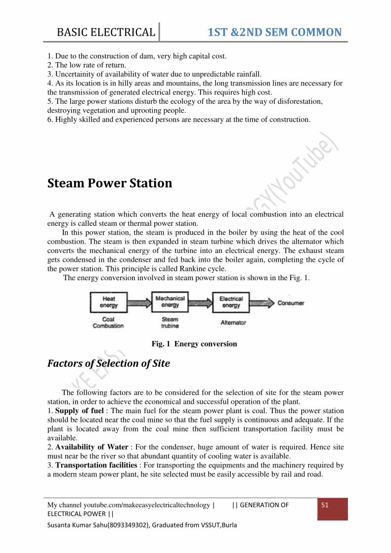
Steam Power Station
A generating station which converts the heat energy of local combustion into an electrical
energy is called steam or thermal power station.
In this power station, the steam is produced in the boiler by using the heat of the cool
combustion. The steam is then expanded in steam turbine which drives the alternator which
converts the mechanical energy of the turbine into an electrical energy. The exhaust steam
gets condensed in the condenser and fed back into the boiler again, completing the cycle of
the power station. This principle is called Rankine cycle.
The energy conversion involved in steam power station is shown in the Fig. 1.
Fig. 1 Energy conversion
Factors of Selection of Site
The following factors are to be considered for the selection of site for the steam power
station, in order to achieve the economical and successful operation of the plant.
1. Supply of fuel : The main fuel for the steam power plant is coal. Thus the power station
should be located near the coal mine so that the fuel supply is continuous and adequate. If the
plant is located away from the coal mine then sufficient transportation facility must be
available.
2. Availability of Water : For the condenser, huge amount of water is required. Hence site
must near be the river so that abundant quantity of cooling water is available.
3. Transportation facilities : For transporting the equipments and the machinery required by
a modern steam power plant, he site selected must be easily accessible by rail and road.
BASIC ELECTRICAL 1ST &2ND SEM COMMON
My channel youtube.com/makeeasyelectricaltechnology | || GENERATION OF
ELECTRICAL POWER ||
52
Susanta Kumar Sahu(8093349302), Graduated from VSSUT,Burla
4. Cost and type of land : The land must be available at a reasonable price to keep the initial
cost low. There must be provision for the extension of the plant. The type of the land must be
such that it should be able to withstand the weight of the heavy equipments to be installed.
5. Distance from load centers : To keep the cost of the transmission and transmission losses
to minimum, the site must be nearer to the load centers. For d.c. system, transmission loss
plays an important role but a.c. power can be transmitted at high voltage with reduced
transmission cost. Thus this factor is more important for d.c. supply system.
6. Distance from populated area : The continuous burning of coal at the power station
produces smoke, Fumes and ash, which pollutes the surrounding area. Such a pollution due to
smoke is dangerous for the people living around. Hence the site of the plant must be at a
considerable distance from the populated area.
All these factories affect the selection of site for the steam power station.
General Arrangement of Steam Power Plant
Though steam power plant simply involves the conversion of heat energy to the
mechanical energy, it requires many types of supporting arrangements. The Fig. 2 shows the
schematic arrangement of steam power station.
The coal is burnt in a place called grate in a boiler. The flue gases are evolved which
heats the water in a boiler. The water is converted to a steam by absorbing heat from the flue
gases. This steam is called wet steam as it contains suspended water particles. This steam is
passed to the superheater where it is converted to superheated steam from the wet steam. This
superheated steam is then expanded in the turbine which rotates the turbine. Thus the heat
energy is converted to a mechanical energy. The turbine shaft is coupled to an alternator
which converts the mechanical energy into an electrical energy. This is then given to the
busbar through a transformer and proper switchgear arrangement.
After expanding in the turbine, the exhaust steam is passed through the condenser. In the
condenser, the steam is converted into liquid condensate. Using the condensate extraction
pump, the condensate is taken to economizer. The economiser again transfer the heat from
flue gases to the condensate and then transfer the heated water to the boiler. Thus the cycle is
completed. The exhaust flue gases are released to the atmosphere through the chimney.
Constituents of Steam Power Station
The various constituents of steam power station can be divided into the following stages
for the ease of understanding the working of the power plant.
1. Fuel and ash circuit 2. Steam generating circuit
3. Steam turbine 4. Alternator
5. Feed water circuit 6. Cooing water circuit

BASIC ELECTRICAL 1ST &2ND SEM COMMON
My channel youtube.com/makeeasyelectricaltechnology | || GENERATION OF
ELECTRICAL POWER ||
53
Susanta Kumar Sahu(8093349302), Graduated from VSSUT,Burla
Fig 2 Schematic arrangement of steam power station
1.3.1 Fuel and Ash Circuit
In steam power plant, the coal is used as a fuel. The coal is stored in a coal storage plant
where coal is transferred from all the parts of the country by the rail or the road. The storage
helps to supply the coal continuously, in case of situations like strikes, failure of

BASIC ELECTRICAL 1ST &2ND SEM COMMON
My channel youtube.com/makeeasyelectricaltechnology | || GENERATION OF
ELECTRICAL POWER ||
54
Susanta Kumar Sahu(8093349302), Graduated from VSSUT,Burla
transportation system etc. Then the coal is transferred to the coal handling plant where the
coal is pulverized i.e. crushed into small pieces. The pulverization increases the surface
exposure of the coal and this helps for rapid combustion of coal without using large quantity
of air. Such a crushed coal is transferred to the boiler from the local handling plant.
As a result of combustion of the coal. large quantity of ash is produced in the boiler. For
the proper combustion of the coal, ash is removed to the ash handling plant. Then it is
delivered to the ash storage plant, from where it is disposed off.
1.3.2 Steam Generating Circuit
The main component of steam generating circuit is the boiler. But many other auxiliary
equipments are used so as to completely utilize the heat of flue gases.
1. Boiler : The boiler is a closed vessel where water is converted to the steam using the heat
of the local combustion. Hence the boiler is called steam generator. In the boilers, the grate is
provided for the combustion of coal. The steam produced in the boiler contains suspended
water particles and hence called wet steam.
2. Superheater : It is an accessory attached to the boiler and located in the path of flue gases
leaving the boiler and flowing towards chimney. By using the heat of the flue gases, the
superheater converts the wet steam into superheated dry steam. There are two advantages of
superheating that it increases the overall efficiency and it avoids the corrosion of the turbine
blades due to wet steam. The superheated steam is then passed to the turbine through a main
valve between the two. The two types of superheaters used are radiant type and convection
type.
3. Economizer : It is another accessory attached to the boiler and located in the path of flue
gases. Thus it utilizes the heat of flue gases which would otherwise wasted to the atmosphere.
The water from the feed pump is passed through the economizer to the boiler drum so that
before entering the boiler, it is heated and hence less efforts are required to convert it into
steam. This increases the overall boiler efficiency, saves the fuel and reduces the stress on the
boiler.
4. Air preheater : This is also an accessory attached to the boiler and located in the path of
flue gases. The air is required for the local combustion. Air is drawn from the atmosphere by
a forced draught fan and is supplied to the air preheater. The air preheater extracts the heat
from the flue gases and makes the air hot before supplying to the boiler. This increases the
temperature of the furnace and helps in the production of the steam. This increases the
thermal efficiency and the steam capacity per square meter of the boiler surface.
The two types of air preheaters used are recuperative type and the other is regenerative
type.
1.3.3 Steam Turbines
The dry and superheated steam from the supeheater is supplied to the turbine. The hat
energy of the steam is converted to the mechanically energy as steam passes over the turbine
blades. There are two types of steam prime movers available, steam engine and steam
turbine. The steam turbine is practically used because of the following advantages,
i) High efficiency ii) Simple construction iii) Low maintenance
iv) High speed v) Less floor area vi) No flywheel required
vii) Less problems of vibrations
The steam turbines are classified into two types as impulse turbine and reaction turbine.
In the impulse turbine, the steams expands completely in the nozzle and pressure over the
moving blades remaining constant. While doing so, the steam attains very high velocity and

BASIC ELECTRICAL 1ST &2ND SEM COMMON
My channel youtube.com/makeeasyelectricaltechnology | || GENERATION OF
ELECTRICAL POWER ||
55
Susanta Kumar Sahu(8093349302), Graduated from VSSUT,Burla
impacts on moving blades giving rise to an impulsive force on them. Thus the turbines starts
rotating.
In the reaction turbine, steam is partially expanded in the stationary nozzle and
remaining expansion takes place on the moving blades. This causes reaction force on the
moving blades and the turbine stats rotating.
The commercial turbines nowadays use series combination of impulse and reaction
turbines, due to which steam can be used more efficiently.
1.3.4 Alternator
The alternator shaft is coupled to the turbine. When the turbine shaft rotates, the
alternator shaft rotates and converts the mechanical energy into an electrical energy. The
electrical energy from the alternator is given to the busbar through transformer, circuit
breakers and isolators.
1.3.5 Feed Water Circuit
The condensate leaving the condenser is used as the feed water. Because it goes to the
boiler, It is first heated in a closed feed water heater. Then it is passed to economizer where it
is further heated and then passed to the boiler. This increases the overall efficiency of the
plant.
The feed water source is generally river or a canal. It contains suspended and dissolved
impurities. The boilers needs clean and soft water for loner life and better efficiency. Hence
the feed water is purified. It is stored in the tanks and by the different actions like
sedimentation, filtration etc., it is made soft and pure. Such a pure feed water is used for the
steam generation in the boiler.
1.3.6 Cooling Water Circuit
For improving the plant efficiency, the expanded steam coming out of the turbine,
passes through the condenser where it is condensed into water. The condenser is very
important as it creases a very low pressure at the exhaust of the turbine thus helps in the
expansion of steam in the turbine at low pressure.
For condensation of steam, a flow of natural cold water is circulated through the
condenser. This takes the heat from the exhaust steam and gets heated. This hot water is
discharged at a suitable location or is passed through a cooling tower so that it is again
converted to cold water. Then it is recirculated through the condenser by a pump. The
condensed steam can be used as a feed water to the boiler.
The two types of condensers used are jet condenser and surface condenser.
Advantages
1. The fuel used is a coal, which is cheap.
2. The initial cost is less compared to other power station.
3. It requires less floor space area compared to hydro-electric power station.
4. The fuel is easily available.
5. The fuel can be easily transported top the site hence site can be anywhere ad not always
near the coal mines.
6. The cost of the generation is less than the diesel.
Disadvantages

BASIC ELECTRICAL 1ST &2ND SEM COMMON
My channel youtube.com/makeeasyelectricaltechnology | || GENERATION OF
ELECTRICAL POWER ||
56
Susanta Kumar Sahu(8093349302), Graduated from VSSUT,Burla
1. Due to the smoke and fume, pollutes the surrounding atmosphere.
2. Running cost is higher than hydro-electric power palnt
3.11. Efficiency
For a steam power station, two efficiencies are defined which are thermal efficiency and
the overall efficiency.
The thermal efficiency is the ratio of heat equivalent of the mechanical energy
transmitted to the turbine shaft to the heat of the combustion of coal.
The overall efficiency is the ratio of heat equivalent of electrical output from alternator to
the heat of coal combustion. The overall efficiency pf steam power station is very low about
20 to 25%.
The overall efficiency depends on number of factors and hence can be expressed as,
Where,
ηelectrical = Electrical efficiency of an alternator which is practically high, above 90%.
ηboiler = Boiler efficiency considering the effect of economizer and air preheater, which is
about 85%.
Nuclear Power Station A generating station which converts the nuclear energy into an electrical energy is called
nuclear power station.
In such a power station, heavy radioactive elements like uranium (U235
), Thorium
(Th232
), are subjected to the nuclear fission. The fission is breaking of nucleus of heavy atom
into the parts by bombarding neutrons. This is carried out in a special nuclear reactor. During
the nuclear fission, huge amount of energy is released.
The heat energy that released is used in rising the steam at high pressure and
temperature. The steam turbines are operated using the high temperature steam. The turbines
converts the heat energy into a mechanical energy. The turbine drives the alternator which
converts mechanical energy into an electrical energy.
The energy conversion involved in the nuclear power station is shown in the Fig.1.

BASIC ELECTRICAL 1ST &2ND SEM COMMON
My channel youtube.com/makeeasyelectricaltechnology | || GENERATION OF
ELECTRICAL POWER ||
57
Susanta Kumar Sahu(8093349302), Graduated from VSSUT,Burla
Conversion of Nuclear Energy
According to Einstein's hypothesis, the relation between the energy released by the
nuclear reaction of the mass given by,
E = mc2
where E = Energy released in jouls
m = Actual mass converted into energy in kg
c = Velocity of light = 3 x 10⁸
m/s
There are three types of nuclear reaction, radioactive decay, fission and fusion. Out of
this, only fission is used to produce the energy.
The fission reaction is achieved by bombarding an electrically neutral neutron, on the
positively charged nucleus of radioactive element. This results in the sustained reaction to
release two or three neurons for eacj one absorbed in fission.
The immediate products of fission reaction such as xenon (Xe140
) and strontim (Sr94
) are
fission fragments and are the decay products. The complete fission of 1 gm of U235
nucleus
produces 0.948 MW energy per day.
Factors selection of site
The following factors are to be considered for the selection of site for the nuclear power
station.
1. Availability of water : Water is a secondary working fluid and used as a coolant for the
cooling purpose, in the nuclear power station. A huge amount of water is necessary for this
purpose. Hence site must be near the river or canal so that abundant quantity of cooling water
is availabe.
2. Disposal of waste : The immediate products of fission reaction are the waste products
which are radioactive in nature. These can cause problems to the health of the people and
hence must be disposal quickly. Such a waste is either burried in deep pits or disposal off in
the sea. Hence the site should be selected so that their is sufficient arrangement for disposal
of such radioactive waste products.
3. Distance from populated area : The radioactive elements are hazardous to the health of
the people around. There is always danger of presence of radioactivity in the atmosphere near
the plant. Hence as a safety measure the site itself must selected to far away from the

BASIC ELECTRICAL 1ST &2ND SEM COMMON
My channel youtube.com/makeeasyelectricaltechnology | || GENERATION OF
ELECTRICAL POWER ||
58
Susanta Kumar Sahu(8093349302), Graduated from VSSUT,Burla
populated area. Practically a dome is used in the plant, which restricts radioactivity to spread
in the atmosphere.
4. Transportation facilities : For transporting the equipments and the machinery required,
there must be adequate transportation facilities. The site must accessible by a rail or road so
that it is easy for the movement of the workers, working in the plant.
5. Nearness to the load centres : Though the site should be away from the populated area
near the river or sea, it should not be too large distance, due to which transmission cost may
increase tremendously.
6. Cost and type of land : The land price must be reasonable and the bearing capacity of the
land should be good enough to withstand the forces due to heavy equipments of the plant.
All these factors affects the selection of site for the nuclear power station.
General Arrangement of Nuclear Power Plant
The Fig. 2 shows the schematic arrangement of a nuclear power plant.
The entire arrangement can be divided into following stages.
1.Nuclear reactor 2. Heat exchange (Steam generator)
3. Steam turbine 4. Alternator 5. Cooling water circuit.

BASIC ELECTRICAL 1ST &2ND SEM COMMON
My channel youtube.com/makeeasyelectricaltechnology | || GENERATION OF
ELECTRICAL POWER ||
59
Susanta Kumar Sahu(8093349302), Graduated from VSSUT,Burla
Fig.2 Schematic arrangement of nuclear power station

BASIC ELECTRICAL 1ST &2ND SEM COMMON
My channel youtube.com/makeeasyelectricaltechnology | || GENERATION OF
ELECTRICAL POWER ||
60
Susanta Kumar Sahu(8093349302), Graduated from VSSUT,Burla
3.15 Nuclear Reactor This represents that part of a nuclear power plant where U fuel is subjected to a
controlled fission chain reaction, during which tremendously energy is generated.
The Fig. 3 shows the various components of a nuclear reactor and a heat exchanger.
The following are the components of the nuclear reactor.
Fig. 3 Nuclear reactor and heat exchanger
1. Fuel : The commonly used fuel is uranium containing 0.7 % U235
or enriched uranium
containing 1.5 - 2.5 U235
. The fuel is used in the form of rods or plates which are surrounded
by the moderators. The fuel rods are arranged in cluster and the entire assembly is called
core. The minimum amount of the fuel required to maintain the chain reaction is called the
critical mass.
2. Moderators : The main function of the moderators is to reduce the energy of neutrons
evolved during fission. By slowing down the high energy neutron, the possibility of escape of
neutrons is reduced while possibility of absorption of neutrons by fuel to cause further fission
is increased. This also educes the amount of fuel required for the chain reaction. The
commonly used moderators are graphite, beryllium and heavy water. Some other functions of
moderators include prevention of corrosion of fuel element, retain the radioactivity and to
provide structural support.
3. Reflector : The reflector is placed around the core to reflect back some of the neutrons
which may leak out from the surface of the core, without taking part in the fission. A blancket
of reflector can reduce the critical mass required.
4. Control rods : The cadmium rods are used as control rods which are strong neutron
absorber. Thus control rods can regulate the supply of neutrons for chain reaction. If the
number of neutrons are not controlled, there is a possibility of explosion due to large amount
of energy released. By pushing or pulling out of these rods, the rate of chain reaction and
hence the heat produced can be controlled. The control rods are operated automatically as per
the next requirement. The other material used for the control rods is boron or hafinium.

BASIC ELECTRICAL 1ST &2ND SEM COMMON
My channel youtube.com/makeeasyelectricaltechnology | || GENERATION OF
ELECTRICAL POWER ||
61
Susanta Kumar Sahu(8093349302), Graduated from VSSUT,Burla
5. Coolant : The main purpose of the coolant is to transfer heat generated in the reactor core
and use it for the system generation. he coolant in the reactor keeps the temperature of fuel
below safe level by continuous removable of the energy from the core. The liquid metals like
sodium or potassium are used as coolants.
6. Radiation shield : The radiation of a radioactive substances are harmful to the human life.
Hence radiation shield is used to prevent the escape of these radiations to the atmosphere.
Generally 50 to 60 cm thick steel plate and few meters of the concrete outside are used as the
radiation shield.
1.5 Heat exchanger
It is a device which is used to exchange the heat from the primary circuit to the
secondary circuit. The coolant carries the heat in the reactor to the exchanger where it is
exchanged to the water, to convert water to steam. Thus the heat exchanger is nothing but a
steam generator. Once the heat exchanged, the coolant is fed back to the reactor, using the
coolant recirculating pump.
1.6 Steam turbine
The steam generated from the water in the secondary circuit is taken to the steam turbine
through a main valve, where it is expanded. Due to this, turbine starts rotating and thus the
heat energy is converted to a mechanical energy.
1.7 Alternator
The shaft of an alternator is coupled to the turbine shaft. Thus when the turbine rotates,
the alternator starts rotating. The alternator converts mechanical energy into an electrical
energy. The energy output of an alternator is given to the bus bars through transformer,
circuit breakers and isolators.
1.8 Cooling Water Circuit
The expanded steam from the turbine is the exhausted steam which is taken to the
condenser. In the condenser, the steam is condensed into water. For the condensation of
steam , a flow of natural cold water is circulated through the condenser. This water takes heat
from the exhaust steam. This hot water is passed through cooling tower, where it is again
converted to cold water. The it is recirculated through the condenser by pump. The condensed
steam is then recirculated through the secondary circuit of exchanger, using the feed water
pump.
3.16 Advantages
1. The amount of fuel required is very small
2. Three is saving in the transportation cost of fuel as fuel required is less.
3. It requires less space compared to any other type of the power plant.
4. The running cost per unit energy generated is lower than the thermal power plant.
5. It is very much economical.
6. There is a lake of environmental problems which are associated with the thermal power
plant.
7. Large deposits of nuclear fuels are available so such plants can ensure continued supply of
the fuel.
8. It ensures reliability of the operation.
BASIC ELECTRICAL 1ST &2ND SEM COMMON
My channel youtube.com/makeeasyelectricaltechnology | || || 62
Susanta Kumar Sahu(8093349302), Graduated from VSSUT,Burla
3.17. Disadvantages 1. The fuel is very expensive.
2. The fuel is difficult to recover.
3. The capital cost is very high compared to other types.
4. The waste products are radioactive and can cause pollution.
5. The waste disposal problem is severe.
6. The maintenance charges are very high.
7. It is not suitable for the varying load conditions, as the reactor can not respond instantly to
the load fluctuations.
8. The fuel may be misused in weapons.

BASIC ELECTRICAL 1ST &2ND SEM COMMON
My channel youtube.com/makeeasyelectricaltechnology | || CHAPTER 04 || 63
Susanta Kumar Sahu(8093349302), Graduated from VSSUT,Burla
CHAPTER 04
CONVERSION OF ELECTRICAL ENERGY
Introduction A motor is a device which converts an electrical energy into the mechanical energy . The
energy conversion process is exactly opposite to that involved in a d.c. generator. In a
generator the input mechanical energy is supplied by a prime mover while in a d.c. motor,
input electrical energy is supplied by a d.c. supply. The construction of a d.c. machine is
same whether it is a motor or a generator.
Fleming's Right Hnad Rule
If three fingers of a right hand, namely thumb, index finger and middle finger are
outstretched so that every one of them is at right angles with the remaining two, and if this
position index finger is made to point in the direction of lines of flux, thumb in the direction
of the relative motion of the conductor with respect to flux then the outstretched middle
finger gives the direction of the e.m.f. induced in the conductor. Visually the rule can be
represented as shown in the Fig.1.
Fig. 1
This rule mainly gives direction of current which induced e.m.f. in conductor will set up
when closed path is provided to it and used for DC Generator
The principle of operation of a d.c. motor can be stated in a single statement as 'when a
current carrying conductor is placed in a magnetic field' it experiences a mechanical force'. In
a practical d.c. motor, field winding produces a required magnetic field while armature
conductors play a role of a current carrying conductors and hence armature conductors
experience a force. As a conductors are placed in the slots which are in the periphery, the
individual force experienced by the conductors acts as a twisting or turning force on the
armature which is called a torque. The torque is the product of force and the radius at which
this force acts. So overall armature experiences a torque and starts rotating

BASIC ELECTRICAL 1ST &2ND SEM COMMON
My channel youtube.com/makeeasyelectricaltechnology | || CHAPTER 04 || 64
Susanta Kumar Sahu(8093349302), Graduated from VSSUT,Burla
Fleming's left hand rule
The rule states that, 'Outstretch the three fingers of the left hand namely the first finger,
middle finger and thumb such that they are mutually perpendicular to each other. Now point
the first finger in the direction of magnetic field and the middle finger in the direction of the
current then the thumb gives the direction of the force experienced by the conductor'.
The Fleming's left hand rule can be shown as in the Fig
Construction (parts) of a Practical D.C. Machine:
whether a machine is d.c. generator or a motor the construction basically remains the same as
shown in the Fig. 1.
It consists of the following parts :
1.1 Yoke

BASIC ELECTRICAL 1ST &2ND SEM COMMON
My channel youtube.com/makeeasyelectricaltechnology | || CHAPTER 04 || 65
Susanta Kumar Sahu(8093349302), Graduated from VSSUT,Burla
a) Functions :
1. It serves the purpose of outermost cover of the d.c. machine. So that the insulating materials
get protected from harmful atmospheric elements like moisture, dust and various gases like
SO2, acidic fumes etc.
2. It provides mechanical support to the poles.
3. It forms a part of the magnetic circuit. It provides a path of low reluctance for magnetic flux.
The low reluctance path is important to avoid wastage of power to provide same flux. Large
current and hence the power is necessary if the path has high reluctance, to produce the same
flux.
b) Choice of Material : To provide low reluctance path, it must be made up of some magnetic
material. It is prepared by using cast iron because it is cheapest. For large machines rolled steel,
cast steel, silicon steel is used which provides high permeability i.e. low reluctance and gives
good mechanical strength.
1.2 Poles
Each pole is divided into two parts namely, I) Pole core and II) Pole shoe.
This is shown in the Fig. 2.
Fig. 2 Pole Structure
a) Functions of pole core and pole shoe :
1. Pole core basically carries a field winding which is necessary to produce the flux.
2. It directs the flux produced through air gap to armature core, to the next pole.
3. Pole shoe enlarges the area of armature core to come across the flux, which is necessary to
produce larger induced e.m.f. To achieve this, pole shoe has been given a particular shape.
b) Choice of Material : It is made up of magnetic material like cast iron or cast steel. As it
requires a definite shape and size, laminated construction is used. The laminations of required
size and shape are stamped together to get a pole which is then bolted to the yoke.
1.3 Field Winding (F1-F2)
The field winding is wound on the pole core with a definite direction.
a) Functions : To carry current due to which pole core, on which the field winding is placed
behaves as an electromagnet, producing necessary flux.
As it helps in producing the magnetic field i.e. exciting the pole as an electromagnet it is
called Field winding or Exciting winding.
b) Choice of material : It has to carry current hence obviously made up of some conducting
material. So aluminium or copper is the choice. But field coils are required to take any type of
shape and bend about pole core and copper has good pliability i.e. it can bend easily. So copper
is the proper choice.
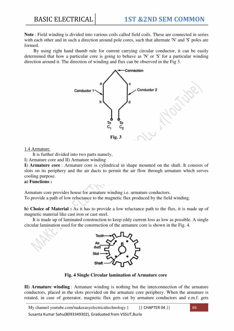
BASIC ELECTRICAL 1ST &2ND SEM COMMON
My channel youtube.com/makeeasyelectricaltechnology | || CHAPTER 04 || 66
Susanta Kumar Sahu(8093349302), Graduated from VSSUT,Burla
Note : Field winding is divided into various coils called field coils. These are connected in series
with each other and in such a direction around pole cores, such that alternate 'N' and 'S' poles are
formed.
By using right hand thumb rule for current carrying circular conductor, it can be easily
determined that how a particular core is going to behave as 'N' or 'S' for a particular winding
direction around it. The direction of winding and flux can be observed in the Fig 3.
Fig. 3
1.4 Armature
It is further divided into two parts namely,
I) Armature core and II) Armature winding
I) Armature core : Armature core is cylindrical in shape mounted on the shaft. It consists of
slots on its periphery and the air ducts to permit the air flow through armature which serves
cooling purpose.
a) Functions :
1. Armature core provides house for armature winding i.e. armature conductors.
2. To provide a path of low reluctance to the magnetic flux produced by the field winding.
b) Choice of Material : As it has to provide a low reluctance path to the flux, it is made up of
magnetic material like cast iron or cast steel.
It is made up of laminated construction to keep eddy current loss as low as possible. A single
circular lamination used for the construction of the armature core is shown in the Fig. 4.
Fig. 4 Single Circular lamination of Armature core
II) Armature winding : Armature winding is nothing but the interconnection of the armature
conductors, placed in the slots provided on the armature core periphery. When the armature is
rotated, in case of generator, magnetic flux gets cut by armature conductors and e.m.f. gets

BASIC ELECTRICAL 1ST &2ND SEM COMMON
My channel youtube.com/makeeasyelectricaltechnology | || CHAPTER 04 || 67
Susanta Kumar Sahu(8093349302), Graduated from VSSUT,Burla
induced in them.
a) Functions :
1. Generation of e.m.f takes place in the armature winding in case of generators.
2. To carry the current supplied in case of d.c. motors.
3. To do the useful work in the external circuit.
b) Choice of material : As armature winding carries entire current which depends on external
load, it has to be made up of conducting material, which is copper.
Armature winding is generally former wound. The conductors are placed in the armature
slots which are lined with tough insulating material.
1.5 Commutator
We have seen earlier that the basic nature of e.m.f. induced in the armature conductors is
alternating. This needs rectification in case of d.c. generator, which is possible by a device called
commutator.
a) Functions :
1. To facilitate the collection of current from the armature conductors.
2. To convert internally developed alternating e.m.f. to unidirectional (d.c.) e.m.f.
3. To produce unidirectional torque in case of motors.
b) Choice of material : As it collects current from armature, it is also made up of copper
segments.
It is cylindrical in shape and is made up of wedge shaped segments of the hard drawn, high
conductivity copper. These segments are insulated from each other by thin layer of mica. Each
commutator segment is connected to the armature conductor by means of copper lug or strip.
This connection is shown in the Fig. 5.
Fig. 5 Commutator
1.6 Brushes and Brush Gear
Brushes are stationary and resting on the surface of the commutator.
a) Function : To collect current from commutator and make it available to the stationary external
circuit.
b) Choice of material : Brushes are normally made up of soft material like carbon.
Brushes are rectangular in shape. They are housed in brush holders, which are usually of box
type. The brushes are made to press on the commutator surface by means of a spring, whose
tension can be adjusted with the help of lever. A flexible copper conductor called pig tail is used

BASIC ELECTRICAL 1ST &2ND SEM COMMON
My channel youtube.com/makeeasyelectricaltechnology | || CHAPTER 04 || 68
Susanta Kumar Sahu(8093349302), Graduated from VSSUT,Burla
to connect the brush to the external circuit. To avoid wear and tear of commutator, the brushes
are made up of soft material like carbon.
1.7 Bearings
Ball-bearings are usually used as they are more reliable. For heavy duty machines, roller
bearings are prederred.
Classification of DC Machines:
DC Machines
Separately Excited Self Excited
Series machine Shunt machine Compound machine
Short shunt Long shunt
compound compound
The d.c. Generator are classified depending upon the way of connecting the field winding
with the armature winding. The difference types of d.c. motors are ;
1. Shunt Generator
2. Series Generator
3. Compound Generator
The compound Generator are further classified as ;
1. Short shunt compound
2. Long shunt compound
Separately Excited Generator When the field winding is supplied from external, separate d.c. supply i.e. excitation of field
winding is separate then the generator is called separately excited generator. Schematic
representation of this type is shown in the Fig.1.

BASIC ELECTRICAL 1ST &2ND SEM COMMON
My channel youtube.com/makeeasyelectricaltechnology | || CHAPTER 04 || 69
Susanta Kumar Sahu(8093349302), Graduated from VSSUT,Burla
Shunt Generator
When the field winding is connected in parallel with the armature and the combination
across the load then the generator is called shunt generator.
The field winding has large number of turns of thin wire so it has high resistance. Let
Rsh be the resistance of the field winding.
Series Generators
When the field winding is connected in series with the armature winding while supplying the
load then the generator is called series generator. It is shown in the Fig. 1.
Field winding, in this case is denoted as S1 and S2. The resistance of series field winding
is very small and hence naturally it has less number of turns of thick cross-section wire as
shown in the Fig.
Fig. Series generator

BASIC ELECTRICAL 1ST &2ND SEM COMMON
My channel youtube.com/makeeasyelectricaltechnology | || CHAPTER 04 || 70
Susanta Kumar Sahu(8093349302), Graduated from VSSUT,Burla
Compound Generator In this type, the part of the field winding is connected in parallel with armature and part in
series with the armature. Both series and shunt field windings are mounted on the same poles.
Depending upon the connection of shunt and series field winding, compound generator is
further classified as : i) Long shunt compound generator, ii) Short shunt compound generator.
1.1 Long Shunt Compound Generator
In this type, shunt field winding is connected across the series combination of armature
and series field winding as shown in the Fig. 1.
Fig. 1 Long shunt compound generato
Short Shunt Compound Generator
In this type, shunt field winding is connected, only across the armature, excluding series
field winding as shown in the Fig. 2.
Fig. 2 Short shunt compound generator
Similar to the d.c. generators, the d.c. motors are classified depending upon the way of
connecting the field winding with the armature winding. The difference types of d.c. motors
are ;
1. Shunt motor
2. Series motors
3. Compound motors
The compound motors are further classified as ;
1. Short shunt compound
2. Long shunt compound

BASIC ELECTRICAL 1ST &2ND SEM COMMON
My channel youtube.com/makeeasyelectricaltechnology | || CHAPTER 04 || 71
Susanta Kumar Sahu(8093349302), Graduated from VSSUT,Burla
Applications of D.C. Motors
Applications of Various Types of Generators
Separately Excited Generators : As a separate supply is required to excite field, the use is restricted to some special
applications like electro-palting, electro-refining of materials etc.
Shunt Generators : Commonly used in battery charging and ordinary lighting purposes.
Series Generators : Commonly used as boosters on d.c. feeders, as a constant current generators for welding
generator and arc lamps.
Cumulatively Compound Generators : These are used for domestic lighting purposes and to transmit energy over long distance.
Differential Compound Generators : The of this type of generators is very rare and it is used for special application like
electric arc welding.
Types of Single Phase Induction Motors In practice some arrangement is provided in the single phase induction motors so as that the
stator flux produced becomes rotating type rather than the alternating type, which rotates in
particular direction only. So torque produced due to such rotating magnetic field is

BASIC ELECTRICAL 1ST &2ND SEM COMMON
My channel youtube.com/makeeasyelectricaltechnology | || CHAPTER 04 || 72
Susanta Kumar Sahu(8093349302), Graduated from VSSUT,Burla
unidirectional as there is no oppositely directed torque present. Hence under the influence of
rotating magnetic field in one direction, the induction motor becomes self starting. It rotates
in same direction as that of rotating magnetic field.
Thus depending upon the methods of producing rotating stator magnetic flux, the single
phase induction motors are classified as,
1. Split phase induction motor
2. Capacitor start induction motor
3. Capacitor start capacitor run induction motor
4. Shaded pole induction motor
Applications of single phase induction motors
Split phase motors have low starting current and moderate starting torque. These are used for
easily started loads like fans, blowers, grinders, centrifugal pumps, washing machines, oil
burners, office equipments etc. These are available in the range of 1/120 to 1/2 kW.
Capacitor starts induction motors have high starting torque and hence are used for hard
starting loads. These are used for compressors, conveyors, grinders, fans, blowers,
refrigerators, air conditions etc. These are most commonly used motors. The capacitor start
capacitor run motors are used in celling fans, blowers and air-circulations. These motors are
available upto 6 kW.
Shaded pole induction motor are cheap but have very low starting torque, low power factor
and low efficiency. These motors are commonly used for the small fans, by motors,
advertising displays, film projectors, record players, gramophones, hair dryers, photo copying
machines etc.
Light: Light is defined as the radiant energy from a hot body causing visual sensation upon the
human eye.
Concept of Lumen:
It is defined as the total quantity of light energy radiated or emitted per second from a
luminous body in the form of light waves
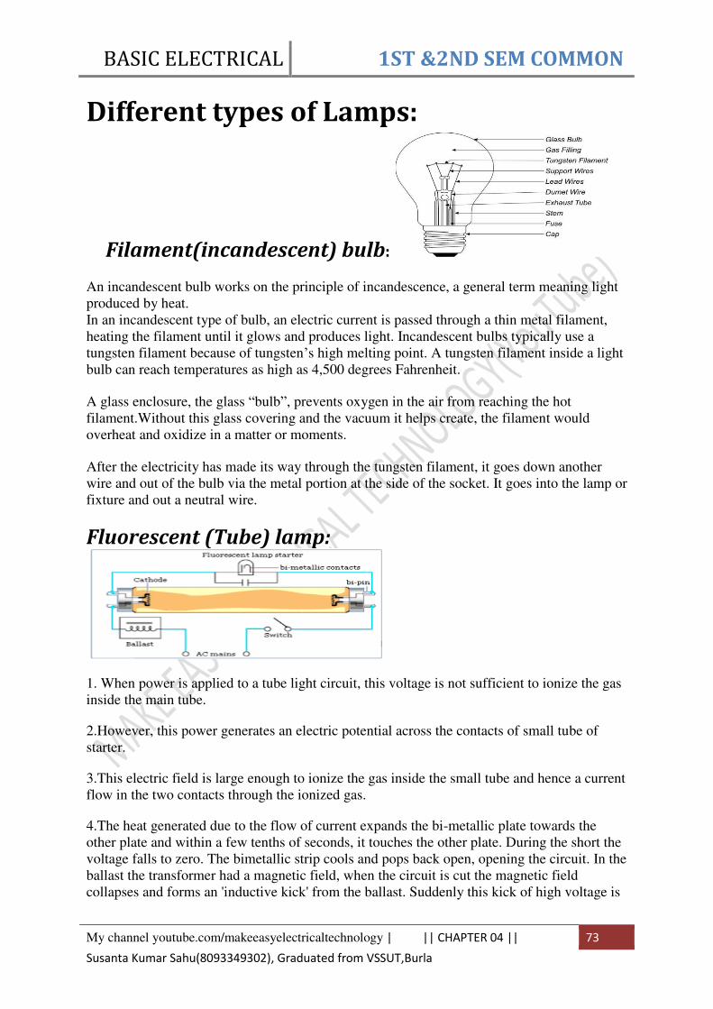
BASIC ELECTRICAL 1ST &2ND SEM COMMON
My channel youtube.com/makeeasyelectricaltechnology | || CHAPTER 04 || 73
Susanta Kumar Sahu(8093349302), Graduated from VSSUT,Burla
Different types of Lamps:
Filament(incandescent) bulb:
An incandescent bulb works on the principle of incandescence, a general term meaning light
produced by heat.
In an incandescent type of bulb, an electric current is passed through a thin metal filament,
heating the filament until it glows and produces light. Incandescent bulbs typically use a
tungsten filament because of tungsten’s high melting point. A tungsten filament inside a light
bulb can reach temperatures as high as 4,500 degrees Fahrenheit.
A glass enclosure, the glass “bulb”, prevents oxygen in the air from reaching the hot
filament.Without this glass covering and the vacuum it helps create, the filament would
overheat and oxidize in a matter or moments.
After the electricity has made its way through the tungsten filament, it goes down another
wire and out of the bulb via the metal portion at the side of the socket. It goes into the lamp or
fixture and out a neutral wire.
Fluorescent (Tube) lamp:
1. When power is applied to a tube light circuit, this voltage is not sufficient to ionize the gas
inside the main tube.
2.However, this power generates an electric potential across the contacts of small tube of
starter.
3.This electric field is large enough to ionize the gas inside the small tube and hence a current
flow in the two contacts through the ionized gas.
4.The heat generated due to the flow of current expands the bi-metallic plate towards the
other plate and within a few tenths of seconds, it touches the other plate. During the short the
voltage falls to zero. The bimetallic strip cools and pops back open, opening the circuit. In the
ballast the transformer had a magnetic field, when the circuit is cut the magnetic field
collapses and forms an 'inductive kick' from the ballast. Suddenly this kick of high voltage is

BASIC ELECTRICAL 1ST &2ND SEM COMMON
My channel youtube.com/makeeasyelectricaltechnology | || CHAPTER 04 || 74
Susanta Kumar Sahu(8093349302), Graduated from VSSUT,Burla
sent through the lamp and this starts the arc. If it didn't work, if the lamp is still too cold, then
the starter switch will light again and repeat the process.
Now the gas of the main tube gets ionized and current starts flowing through it. Thus the bi-
metallic plate of starter cools down re-opening the gap between the two contacts. This gap
will remain open until the tube light will start next time.
LED Bulb:
LEDs are diodes. A diode has a P-N junction across which charge carriers like electrons and
holes pass when current flows through the diode. When forward biased, the electrons from N
region flows to the P region and holes from P region towards N region. Some of the electrons
recombine with the holes at the junction and their energy is radiated outward. By proper
design using suitable materials like indium phosphide or gallium arsenide, we can create a
junction that radiates maximum energy as visible light. This is Light Emittng Diode.
The wavelength of the radiation and hence the colour of the light depends on the materials
used.
To create white light, the junction is designed to emit ultraviolet light. A coat of fluorescent
material absorbs this UV radiation and re-radiates it as white light.
Star rating of home appliances: These days, most major electrical appliances for the kitchen are sold with energy efficiency
labels (also called MEPS labels, short for Minimum Energy Performance Standards).
Refrigerators, ovens, microwaves and dishwashers are all required to carry a label that shows
a star rating, indicating an appliance's overall efficiency.
The idea behind these ratings is to make it as easy as possible for people to be able to
compare the real-world performance and efficiency of the products they're buying without
having to rely on manufacturers' claims or their own subjective calculations.

BASIC ELECTRICAL 1ST &2ND SEM COMMON
My channel youtube.com/makeeasyelectricaltechnology | || CHAPTER 04 || 75
Susanta Kumar Sahu(8093349302), Graduated from VSSUT,Burla
How do energy star ratings work?
The star system and labelling scheme is an easy way to figure out how energy efficient
different appliances will be when compared to other appliances of the same kind.
Under the current system, appliances with up to six stars are known as 'efficient' appliances,
while any more stars than that is enough for the appliance to win a "super efficient" label (see
picture). The maximum efficiency rating is a ten star rating, and appliances can also receive
half-star ratings (e.g. 5 1/2 stars).
In addition to the star ratings, each label will also list the overall estimated energy
consumption of the appliance in kWh, over the period of one year. Using this number, you
should be able to get a reasonable idea of how much the appliance will cost to run over the
course of a year.

BASIC ELECTRICAL 1ST &2ND SEM COMMON
My channel youtube.com/makeeasyelectricaltechnology | || CHAPTER 05 || 76
Susanta Kumar Sahu(8093349302), Graduated from VSSUT,Burla
CHAPTER 05
WIRING AND POWER BILLING
Different Types of Electrical Wiring Systems
The types of internal wiring usually used are
Cleat wiring
Wooden casing and capping wiring
CTS or TRS or PVC sheath wiring
Lead sheathed or metal sheathed wiring
Conduit wiring
There are additional types of conduit wiring according to Pipes installation (Where steel and
PVC pipes are used for wiring connection and installation).
Surface or open Conduit type
Recessed or concealed or underground type Conduit
1. Cleat Wiring
This system of wiring comprise of ordinary VIR or PVC insulated wires (occasionally,
sheathed and weather proof cable) braided and compounded held on walls or ceilings by
means of porcelain cleats, Plastic or wood. Cleat wiring system is a temporary wiring system
therefore it is not suitable for domestic premises. The use of cleat wiring system is over
nowadays.
Advantages of Cleat Wiring:
It is simple and cheap wiring system
Most suitable for temporary use i.e. under construction building or army camping
As the cables and wires of cleat wiring system is in open air, Therefore fault in cablescan
be seen and repair easily.
Cleat wiring system installation is easy and simple.
Customization can be easily done in this wiring system e.g. alteration and addition.
Inspection is easy and simple.
Disadvantages of Cleat Wiring:
Appearance is not so good.
Cleat wiring can’t be use for permanent use because, Sag may be occur after sometime of
the usage.
In this wiring system, the cables and wiring is in open air, therefore,
oil, Steam, humidity, smoke, rain, chemical and acidic effect may damage the cables and
wires.
BASIC ELECTRICAL 1ST &2ND SEM COMMON
My channel youtube.com/makeeasyelectricaltechnology | || CHAPTER 05 || 77
Susanta Kumar Sahu(8093349302), Graduated from VSSUT,Burla
it is not lasting wire system because of the weather effect , risk of fire and wear & tear.
it can be only used on 250/440 Volts on low temperature.
There is always a risk of fire and electric shock.
it can’t be used in important and sensitive location and places.
It is not lasting, reliable and sustainable wiring system.
2. Casing and Capping wiring
Casing and Capping wiring system was famous wiring system in the past but, it is considered
obsolete this days because of Conduit and sheathed wiring system. The cables used in this
kind of wiring were either VIR or PVC or any other approved insulated cables.
The cables were carried through the wooden casing enclosures. The casing is made up of a
strip of wood with parallel grooves cut length wise so as to accommodate VIR cables. The
grooves were made to separate opposite polarity. the capping (also made of wood) used to
cover the wires and cables installed and fitted in the casing.
Advantages of Casing Capping Wiring:
It is cheap wiring system as compared to sheathed and conduit wiring systems.
It is strong and long-lasting wiring system.
Customization can be easily done in this wiring system.
If Phase and Neutral wire is installed in separate slots, then repairing is easy.
Stay for long time in the field due to strong insulation of capping and casing..
It stays safe from oil, Steam, smoke and rain.
No risk of electric shock due to covered wires and cables in casing & capping.
Disadvantages Casing Capping Wiring:
There is a high risk of fire in casing & capping wiring system.
Not suitable in the acidic, alkalies and humidity conditions
Costly repairing and need more material.
Material can’t be found easily in the contemporary
White ants may damage the casing & capping of wood.
3. Batten Wiring (CTS or TRS)
Single core or double core or three core TRS cables with a circular oval shape cables are used
in this kind of wiring. Mostly, single core cables are preferred. TRS cables are chemical
proof, water proof, steam proof, but are slightly affected by lubricating oil. The TRS cables
are run on well seasoned and straight teak wood batten with at least a thickness of 10mm.
The cables are held on the wooden batten by means of tinned brass link clips (buckle clip)
already fixed on the batten with brass pins and spaced at an interval of 10cm for horizontal
runs and 15cm for vertical runs.
Advantages of Batten Wiring
Wiring installation is simple and easy
cheap as compared to other electrical wiring systems
Paraphrase is good and beautiful
Repairing is easy

BASIC ELECTRICAL 1ST &2ND SEM COMMON
My channel youtube.com/makeeasyelectricaltechnology | || CHAPTER 05 || 78
Susanta Kumar Sahu(8093349302), Graduated from VSSUT,Burla
strong and long-lasting
Customization can be easily done in this wiring system.
less chance of leakage current in batten wiring system
Disadvantages of Batten Wiring
Can’t be install in the humidity, Chemical effects, open and outdoor areas.
High risk of firs
Not safe from external wear & tear and weather effects (because, the wires are openly
visible to heat, dust, steam and smoke.
Heavy wires can’t be used in batten wiring system.
Only suitable below then 250V.
Need more cables and wires.
4. Lead Sheathed Wiring
The type of wiring employs conductors that are insulated with VIR and covered with an outer
sheath of lead aluminum alloy containing about 95% of lead. The metal sheath given
protection to cables from mechanical damage, moisture and atmospheric corrosion.
The whole lead covering is made electrically continuous and is connected to earth at the point
of entry to protect against electrolytic action due to leaking current and to provide safety in
case the sheath becomes alive. The cables are run on wooden batten and fixed by means of
link clips just as in TRS wiring.
5. Conduit Wiring There are two additional types of conduit wiring according to pipe installation
1. Surface Conduit Wiring
2. Concealed Conduit Wiring
5.1 Surface Conduit Wiring
If conduits installed on roof or wall, It is known as surface conduit wiring. in this wiring
method, they make holes on the surface of wall on equal distances and conduit is installed
then with the help of rawal plugs.
5.2 Concealed Conduit wiring
If the conduits is hidden inside the wall slots with the help of plastering, it is called concealed
conduit wiring. In other words, the electrical wiring system inside wall, roof or floor with the
help of plastic or metallic piping is called concealed conduit wiring. obliviously, It is
the most popular, beautiful, stronger and common electrical wiring system nowadays.
In conduit wiring, steel tubes known as conduits are installed on the surface of walls by
means of pipe hooks (surface conduit wiring) or buried in walls under plaster and VIR or
PVC cables are afterwards drawn by means of a GI wire of size if about 18SWG.

BASIC ELECTRICAL 1ST &2ND SEM COMMON
My channel youtube.com/makeeasyelectricaltechnology | || CHAPTER 05 || 79
Susanta Kumar Sahu(8093349302), Graduated from VSSUT,Burla
Layout of household electrical wiring (single line
diagram):
Basic protective devices used in house
hold wiring.:-
Fuses, MCBs, RCDs, and RCBOs are all devices used to protect users and equipment from
fault conditions in an electrical circuit by isolating the electrical supply. With fuses and
MCBs only the live feed is isolated; with RCDs and RCBOs both the live and neutral feeds
are isolated.
Fuses
A fuse is a very basic protection device which is destroyed (i.e. it 'blows')
and breaks the circuit should the current exceed the rating of the fuse. Once the fuse has
blown, it needs to be replaced.
In older equipment, the fuse may just be a length of appropriate fuse wire fixed between two
terminals (normally screw terminals). These are becoming rarer as electrical installations are
updated - the presence of such fuses usually indicates that it is about time that the installation
is updated.

BASIC ELECTRICAL 1ST &2ND SEM COMMON
My channel youtube.com/makeeasyelectricaltechnology | || CHAPTER 05 || 80
Susanta Kumar Sahu(8093349302), Graduated from VSSUT,Burla
Modern fuses are generally incorporated within sealed ceramic cylindrical body (or cartridge)
and the whole cartridge needs to be replaced.
Cartridge fuses are used in older type consumer units, fused sockets, fused plugs etc.
Miniature Circuit Breaker (MCB)
An MCB is a modern alternative to fuses used in Consumer Units (Fuse
Boxes). They are just like switches which switch off when an overload is detected in the
circuit. The advantage of MCBs over fuses is that if they trip, they can be reset - they also
offer a more precise tripping value.
Residual Current Device (RCD)Modern alternatives (better) to Earth Leakage Circuit
Breakers and fuses in the Consumer Unit. RCDs are tripped if they detect a small current
imbalance between the Live and Neutral wires above the trip value - this is typically
30mA.RCDs can be wired to protect a single or a number of circuits - the advantage of
protecting individual circuits is that if one circuit trips, it will not shut down the whole house,
just the protected circuit.RCDs are available in at least 4 basic configurations:
1. As hard wired in units, where both the inputs and outputs are wired
into the unit - ideal for a workshop etc where all the sockets within can be protected.
Each individual circuit taken from the RCD is protected by a MCB of an appropriate
value.
2. As protected outlets - normally a protected socket can be fitted as a
direct replacement for a standard, no protected outlet socket.

BASIC ELECTRICAL 1ST &2ND SEM COMMON
My channel youtube.com/makeeasyelectricaltechnology | || CHAPTER 05 || 81
Susanta Kumar Sahu(8093349302), Graduated from VSSUT,Burla
3. As a plug-in unit which can convert any socket into to a protected
circuit - this gives good flexibility as, for example, a lawn mower or a hedge trimmer
can be plugged in at different times. However, as the individual appliance could still
be plugged into an unprotected socket, you need to remember to fit the
4. As a plug for wiring on to the lead of an individual appliance, this
does make it less flexible than the plug-in unit above but it does ensure that the piece
of equipment is always protected. One very usefully use to to fit it to the end of an
extension cable, then whatever you plug into the extension lead is protected.
Residual Current Breaker with Overload protection (RCBO)
A RCBOs combines the functions of a MCB and a RCD in one unit. They
are used to protect a particular circuit, instead of having a single RCD for the whole building.
Generally these are used more often in commercial building than domestic ones.

BASIC ELECTRICAL 1ST &2ND SEM COMMON
My channel youtube.com/makeeasyelectricaltechnology | || CHAPTER 05 || 82
Susanta Kumar Sahu(8093349302), Graduated from VSSUT,Burla
Energy consumed in a small electrical
installation:
Electrical energy:
The energy consumed by an appliance for a time period t is given by the product of the
power(P) ratings (in kw) and time(T) (in hour) .
E=P*T
It’s unit is kwh, 1kwh is known as 1 unit
1hp(Horse power)=746 watt
Problem:
Calculate the electricity bill amount for a month of April, if 4 bulbs of 40 W for 5 h, 4
tubelights of 60 W for 5 h, a TV of 100 W for 6 h, a washing machine of 400 W for 3 h are
used per day. The cost per unit is Rs 1.80.
Solutions:
Electric energy consumed per day by 4 bulbs = 4x40 x5 = 800Wh
Electric energy consumed per day by 4 lights = 4x60x5 =1200 Wh
Electric energy consumed per day by TV = 100x6 = 600 Wh
Electric energy consumed per day by washing machine = 400x3 =1200 Wh
.’. Total electric energy consumed by all electric appliances
= (800+ 1200 + 600+ 1200)Wh = 3800 Wh = 3.8 kWh =3.8 units
Total electric energy consumed in the month of April (30 days) = 3.8 x 30 = 114units
Cost of one unit = Rs. 1.80
Cost of 114 units = 114 x 1.80 = 205.20
.:. Electricity bill amount = Rs 205.20
BASIC ELECTRICAL 1ST &2ND SEM COMMON
My channel youtube.com/makeeasyelectricaltechnology | || CHAPTER 06 || 83
Susanta Kumar Sahu(8093349302), Graduated from VSSUT,Burla
CHAPTER 06
MEASURING INSTRUMENTS
Introduction: The measurement of a given quantity is the result of comparison between the quantity to be
measured and a definite standard. The instruments which are used for such measurements are
called measuring instruments. The three basic quantities in the electrical measurement are
current, voltage and power. The measurement of these quantities is important as it is used for
obtaining measurement of some other quantity or used to test the performance of some
electronic circuit or components etc.
The necessary requirements for any measuring instruments are
1- With the introduction of the instrument in the circuit, the circuit conditions should not be
altered.
2- The power consumed by the instruments for their operation should be as small as possible.
The instruments which measure the current flowing in the circuit is called ammeter while
the instrument which measures the voltage across any two points of a circuit is called
voltmeter.
Torques in instruments: In case of measuring instruments, the effect of unknown quantity is converted into a
mechanical force which is transmitted to the pointer which moves over a calibrated scale. The
moving system of such instrument is mounted on a pivoted spindle. For satisfactory operation
of any indicating instrument, following system must be present in an instrument.
1) Deflecting system producing deflecting torque Td
2) Controlling system producing damping torque Tc
3) Damping system producing damping torque.
Deflecting System
In most of the indicating instruments the mechanical force proportional to the quantity to be
measured is generated. This force or torque deflects the pointer. The system which produces
such a deflecting torque is called deflecting system and the torque is denoted as The
deflecting torque overcomes,
1) The inertia of the moving system
2) The controlling torque provided by controlling system.
3) The damping torque provided by damping system.
The deflecting system uses on of the following effects produced by current or voltage, to
produce deflecting torque.

BASIC ELECTRICAL 1ST &2ND SEM COMMON
My channel youtube.com/makeeasyelectricaltechnology | || CHAPTER 06 || 84
Susanta Kumar Sahu(8093349302), Graduated from VSSUT,Burla
Controlling System
This system should provided a force so that current or any other electrical quantity will
produce deflection of the pointer proportional to its magnitude. The important functions of
this system are,
1) It produces a force equal and opposite to the deflecting force in order to make the
deflection of pointer at a definite magnitude. If this system is absent, then the pointer will
swing beyond its final steady positions for the given magnitude and deflection will become
indefinite.
2) It brings the moving system back to zero position when the force which causes the
movement of the moving system is removed. It will never come back to its zero position in
the absence of controlling system.
Controlling torque is generally provided by springs. Sometimes gravity control is also
used.
Damping System
The deflecting torque provides some deflection and controlling torque acts in the opposite
direction to that of deflection torque. So before coming to the rest, pointer always oscillates
due to inertia, about the equilibrium position. Unless pointer rests, final reading cannot be
obtained. So to bring the pointer to rest within short time, damping system is required. The
system should provide a damping torque only when the moving system is in motion.
Damping torque is proportional to velocity of the moving system but it does not depend on
operating current. It must not affect controlling torque or increase the friction.
The quickness with which the moving system settles to the final steady position depends
on relative damping.
Permanent Magnet Moving Coil
Instruments (PMMC) The permanent magnet moving coil instruments are most accurate type for d.c.
measurements. The action of these instruments is based on the motoring principle. When a
current carrying coil is placed in the magnetic field produced by permanent magnet, the coil
experiences a force and moves. As the coil is moving and the magnet is permanent, the
instrument is called permanent magnet moving coil.

BASIC ELECTRICAL 1ST &2ND SEM COMMON
My channel youtube.com/makeeasyelectricaltechnology | || CHAPTER 06 || 85
Susanta Kumar Sahu(8093349302), Graduated from VSSUT,Burla
Fig. 1. Construction of PMMC instrument
The moving coil is either rectangular or circular in shape. it has number of turns of fine
wire. The coil is suspended so that it is free to turn about its vertical axis. The coil is placed in
uniform, horizontal and radial magnetic field of a permanent magnet in the shape of a horse-
shoe. The iron core is spherical if coil is circular and is cylindrical if the coil is rectangular.
Due to iron core, the deflecting torque increases, increasing the sensitivity of the instrument.
The controlling torque is provided by two phosphor bronze hair springs.
The damping torque is provided by eddy current damping. It is obtained by movement of
the aluminium former, moving the magnetic field of the permanent magnet.
The pointer is carried by the spindle and it moves over a graduated scale. The pointer has
light weight so that it can deflect rapidly. The mirror is placed below the pointer to get the
accurate reading by removing the parallax. The weight of the instrument is normally counter
balanced by the weights situated diametrically opposite and rigidly connected to it. The scale
markings of the basic d.c. PMMC instruments are usually linearly spaced as the deflecting
torque and hence the pointer deflection and directly proportional to the current passing
through the coil.
The top view of PMMC instrument is shown in the Fig. 2.

BASIC ELECTRICAL 1ST &2ND SEM COMMON
My channel youtube.com/makeeasyelectricaltechnology | || CHAPTER 06 || 86
Susanta Kumar Sahu(8093349302), Graduated from VSSUT,Burla
Fig. 2 PMMC instrument
In a practical PMMC instrument, a Y shaped member is attached to the fixed end of the
front control spring. An eccentric pin through the instrument case engages the Y shaped
member so that the zero position of the pointer can be adjusted from outside.
1.1 Torque Equation
The equation for the developed torque can be obtained from the basic low of the
electromagnetic torque. The deflecting torque is given by,
Td = NBAI
where Td = deflecting torque in N-m
B = flux density in air gap, Wb/m2
N = number of turns of the coil
A = Effective coil area m2
I = Current in the moving coil, amperes
Td = GI
where G = NBA = constant
The controlling torque is provided by the springs and is proportional to the angular
deflection of the pointer.
Tc = kθ
where Tc = controlling torque
K = spring constant, Nm/rad or Nm/deg
θ = angular deflection
for the final steady state position,
Td = Tc
GI = Kθ
θ = (G/K) I
I = (K/G)θ
Note: Thus the deflection is directly proportional to the current passing through the coil.
The pointer deflection can therefore be used to measure current.

BASIC ELECTRICAL 1ST &2ND SEM COMMON
My channel youtube.com/makeeasyelectricaltechnology | || CHAPTER 06 || 87
Susanta Kumar Sahu(8093349302), Graduated from VSSUT,Burla
As the direction of the current through the coil changes, the direction of the deflection of
the pointer is also changes. Hence such instrument are well suited for the d.c. measurements.
Moving Iron Instruments The moving iron instruments are classified as:
i) Moving iron attraction type instruments and
ii) Moving iron repulsion type instruments
1.1 Moving iron attraction type instruments
The basic working principle of these instruments is very simple that a soft iron piece if
brought near the magnet gets attracted by the magnet.
The construction of the attraction type instrument is shown in the Fig.1.
Fig. 1 Moving iron attraction type instruments
It consists of a fixed coil C and moving iron piece D. The coil is flat and has a narrow
slot like opening. The moving iron is a flat disc which eccentrically mounted. on the spindle.
The spindle is supported between the jewel bearings. The spindle caries a pointer which
moves over a graduated scale. The number of turns of the fixed coil are dependent on the
range of the instrument. For passing current through the coil only few turns are required.
The controlling torque is provided by the springs but gravity control may also ne used for
vertically mounted panel type instruments.
The damping torque is provided by the air friction. A light aluminium piston is attached
to the moving system. It moves in a fixed chamber. The chamber is closed at one end. It can
also provided with the help of van attached to the moving system.
The operating magnetic field in moving iron instruments is very weak. Hence eddy
current damping is not used since it require a permanent magnet which would affect or
distort the operating field.
1.2 Moving Iron Repulsion Type Instrument
These instruments have two vanes inside the coil, the one is fixed and other is movable.
When the current flows in the coil, both the vanes are magnetised with like polarities induced
on the same side. Hence due to repulsion of like polarities, there is a force of repulsion
between the two vanes causing the movement of the moving van. The repulsion type
instruments are the most commonly used instruments.

BASIC ELECTRICAL 1ST &2ND SEM COMMON
My channel youtube.com/makeeasyelectricaltechnology | || CHAPTER 06 || 88
Susanta Kumar Sahu(8093349302), Graduated from VSSUT,Burla
Connection diagram of Ammeter, voltmeter:
Connection diagram of wattmeter (single phase):
The wattmeter is an instrument for measuring the electric power in watts of any given circuit.
The internal construction of a wattmeter is such that it consists of two coils. One of the coil is
in series and the other is connected in parallel. The coil that is connected in series with the
circuit is known as the current coil and the one that is connected in parallel with the circuit is
known as the voltage coil.

BASIC ELECTRICAL 1ST &2ND SEM COMMON
My channel youtube.com/makeeasyelectricaltechnology | || CHAPTER 06 || 89
Susanta Kumar Sahu(8093349302), Graduated from VSSUT,Burla
This is shown in given circuit diagram. This is basic construction of any wattmeter.
Connection diagram of Energy meter:

BASIC ELECTRICAL 1ST &2ND SEM COMMON
My channel youtube.com/makeeasyelectricaltechnology | || CHAPTER 06 || 90
Susanta Kumar Sahu(8093349302), Graduated from VSSUT,Burla
DISCLAIMER
COPYRIGHT IS NOT RESERVED BY AUTHORS. AUTHORS ARE NOT RESPONSIBLE
FOR ANY LEGAL ISSUES ARISING OUT OF ANY COPYRIGHT DEMANDS AND/OR
REPRINT ISSUES CONTAINED IN THIS MATERIALS. THIS IS NOT MEANT FOR ANY
COMMERCIAL PURPOSE & ONLY MEANT FOR PERSONAL USE OF STUDENTS
FOLLOWING SYLLABUS. READERS ARE REQUESTED TO SEND ANY TYPING
ERRORS CONTAINED, HEREIN.
To get all the Concepts on Electrical Engineering: Follow on:
Channel: Make Easy Electrical Technology
Search In Google: Makeeasyet