basic electrical technology det 211/3 chapter 3 - three phase system
TRANSCRIPT

BASIC ELECTRICAL TECHNOLOGY
DET 211/3
Chapter 3 - Three Phase System
• Thinner conductors can be used to transmit the same kVA at the same voltage, which reduces the amount of copper required (typically about 25% less) and turn reduces construction and maintenance costs.
• The lighter lines are easier to install, and the supporting structures can be less massive and farther apart.
• In general, most larger motors are three phase because they are essentially self starting and do not require a special design or additional starting circuitry.
INTRODUCTION TO THREE PHASE SYSTEM
In general, three phase systems are preferred over single phase systems for the transmission of the power system for many reasons, including the following:
Three phase voltages
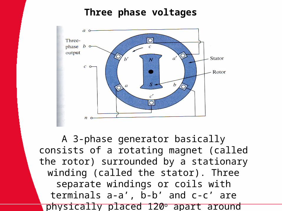
A 3-phase generator basically consists of a rotating magnet (called the rotor) surrounded by a
stationary winding (called the stator). Three separate windings or coils with terminals a-a’, b-b’ and c-c’ are physically placed 120o apart around
the stator.
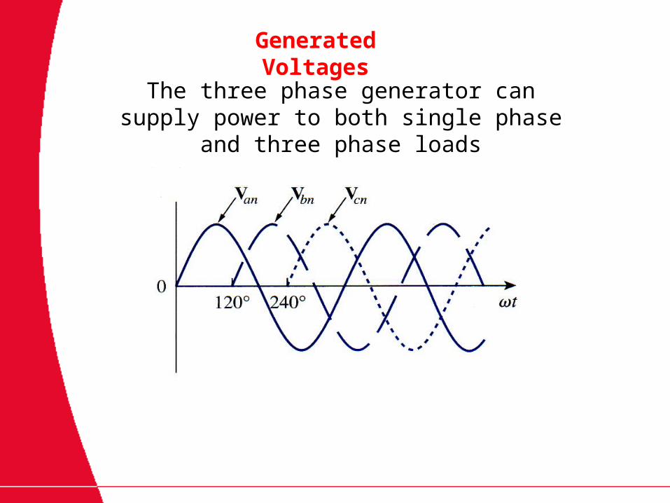
Generated Voltages
The three phase generator can supply power to both single phase and three phase loads
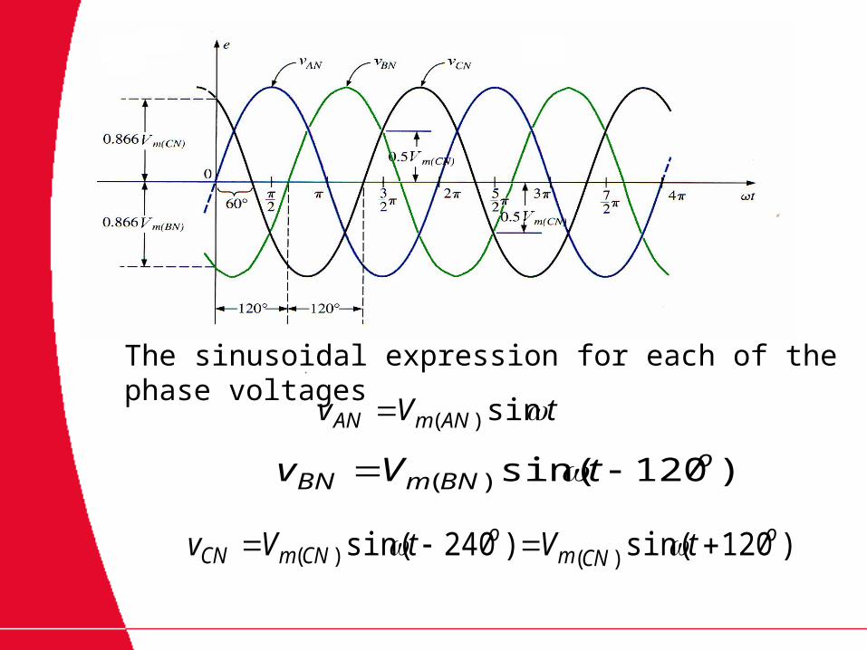
tVv ANmAN sin)(
)120sin()(o
BNmBN tVv
)120sin()240sin( )()(o
CNmo
CNmCN tVtVv
The sinusoidal expression for each of the phase voltages
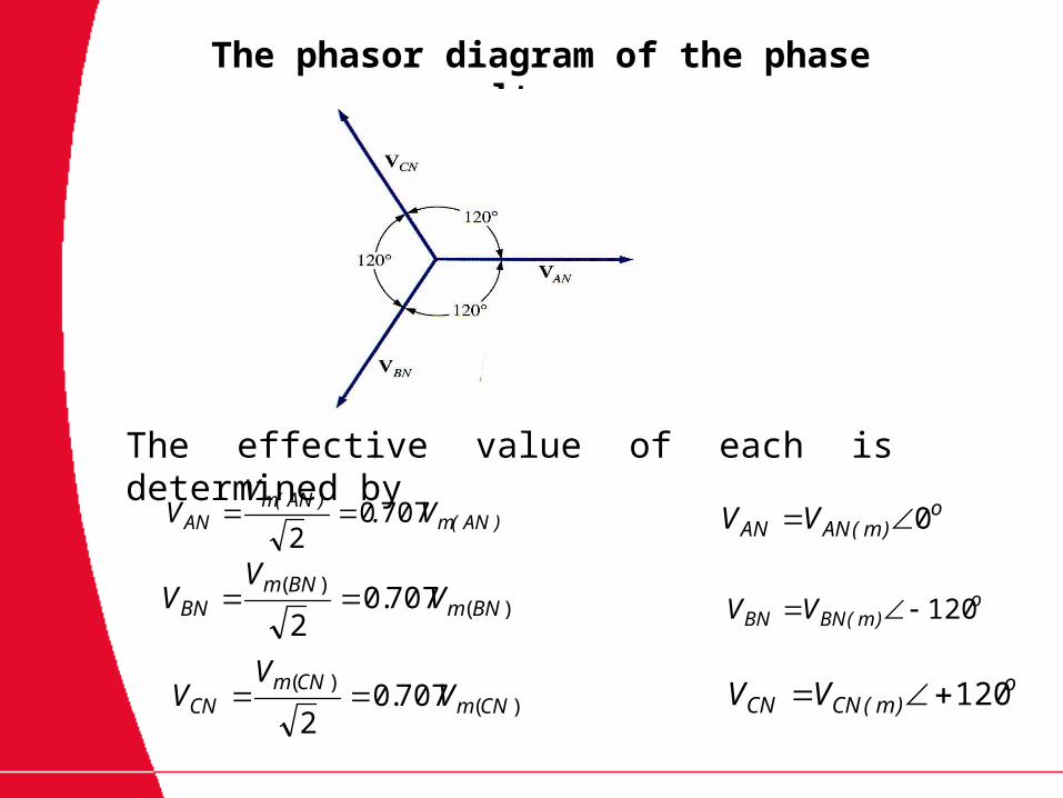
The phasor diagram of the phase voltages
)AN(m)AN(m
AN V.V
V 70702
)()( 707.0
2BNm
BNmBN V
VV
)()( 707.0
2CNm
CNmCN V
VV
o)m(ANAN VV 0
o)m(BNBN VV 120
o)m(CNCN VV 120
The effective value of each is determined by
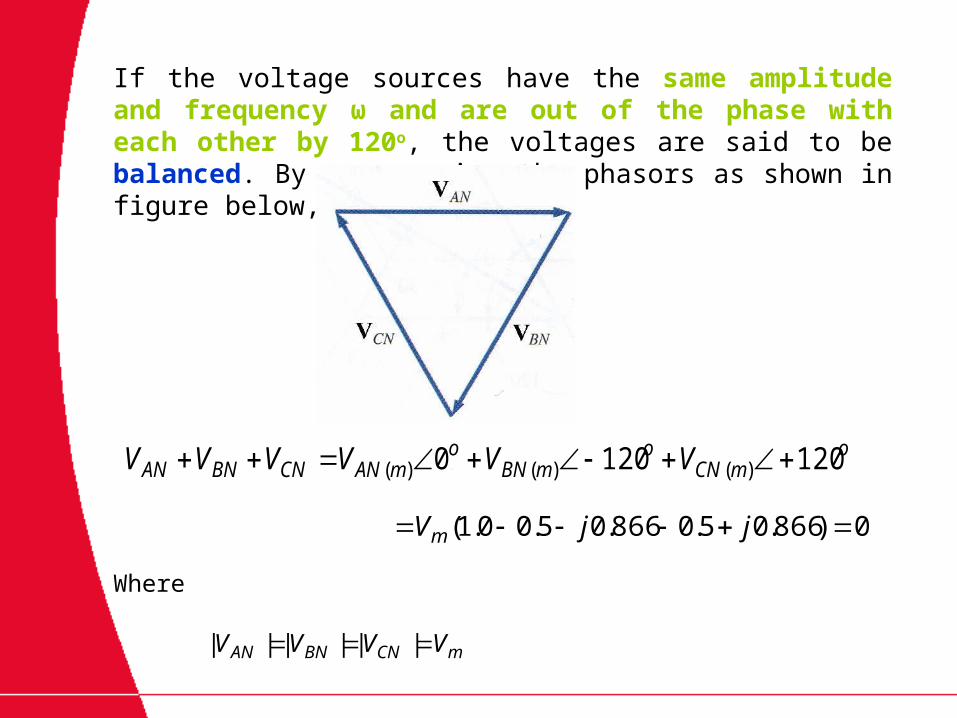
If the voltage sources have the same amplitude and frequency ω and are out of the phase with each other by 120o, the voltages are said to be balanced. By rearranging the phasors as shown in figure below, so
omCN
omBN
omANCNBNAN VVVVVV 1201200 )()()(
0)866.05.0866.05.00.1( jjVm
mCNBNAN VVVV ||||||
Where
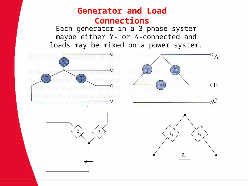
Generator and Load Connections
Each generator in a 3-phase system maybe either Y- or -connected and loads may be mixed on a power
system.
Z
Z Z Z
Z
Z

Wye Connected Generator
gL II
NBANBNANAB VVVVV
NCBNCNBNBC VVVVV
NACNANCNCA VVVVV
Applying KVL around the indicated loop in figure above, we obtain

Wye Connected Generator
BAAB VVV
00 1200 VV
For line-to-line voltage VAB is given by:
VjVV
2
3
2
1
VjV2
3
2
3
2
1
2
33 jV
0303 V
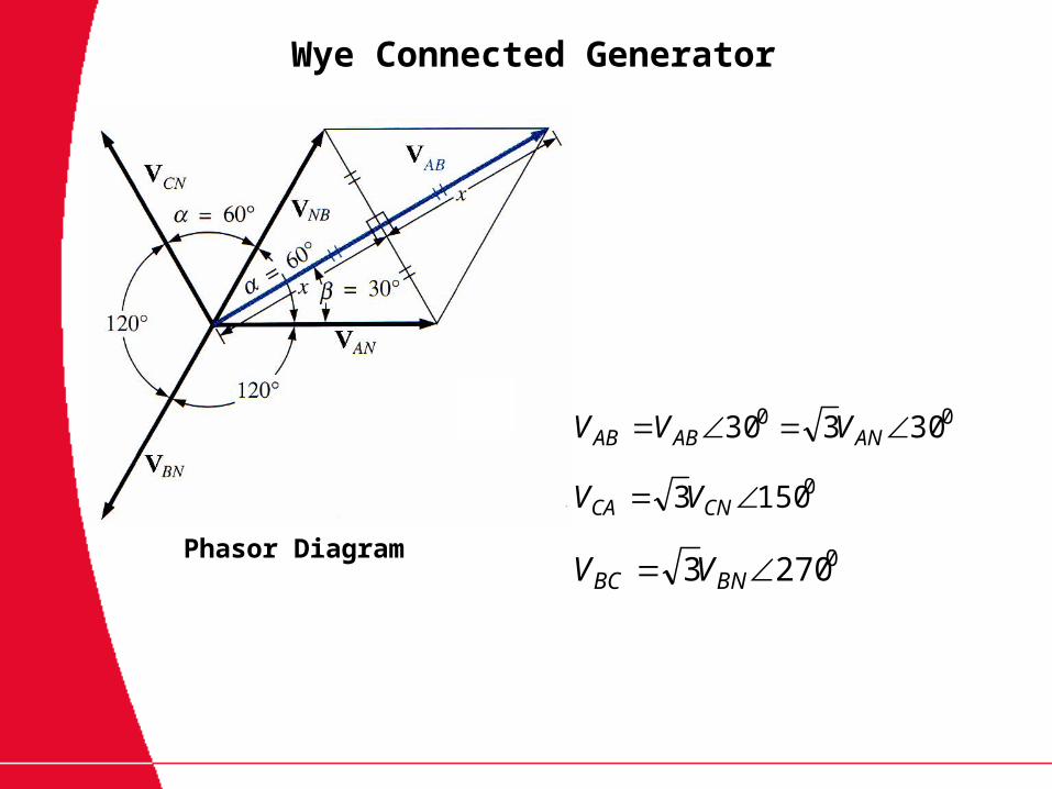
Phasor Diagram
00 30330 ANABAB VVV
01503 CNCA VV
02703 BNBC VV
Wye Connected Generator
Wye Connected Generator
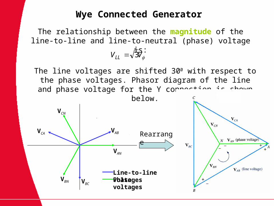
VVLL 3
The relationship between the magnitude of the line-to-line and line-to-neutral (phase) voltage is:
The line voltages are shifted 300 with respect to the phase voltages. Phasor diagram of the line and phase voltage for the Y
connection is shown below.
RearrangeVAB
VAN
VBCVBN
VCA
VCN
Line-to-line voltagesPhase voltages
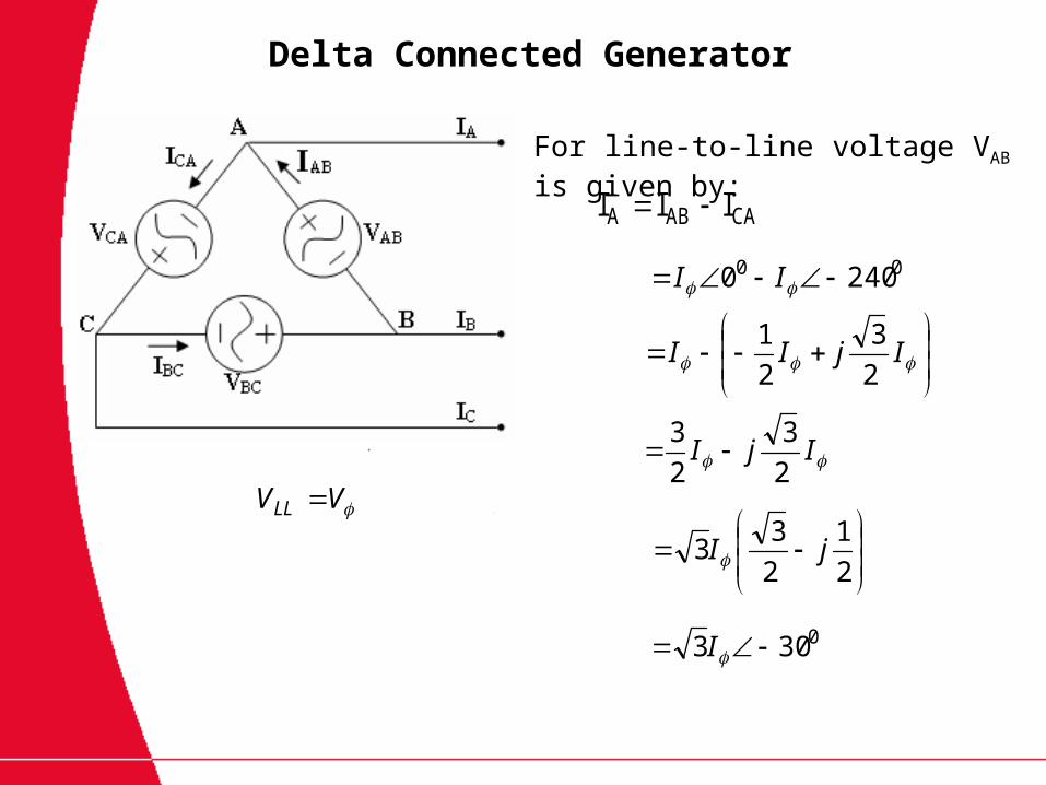
Delta Connected Generator
VVLL
CAABA III
00 2400 II
For line-to-line voltage VAB is given by:
IjII
2
3
2
1
IjI2
3
2
3
2
1
2
33 jI
0303 I
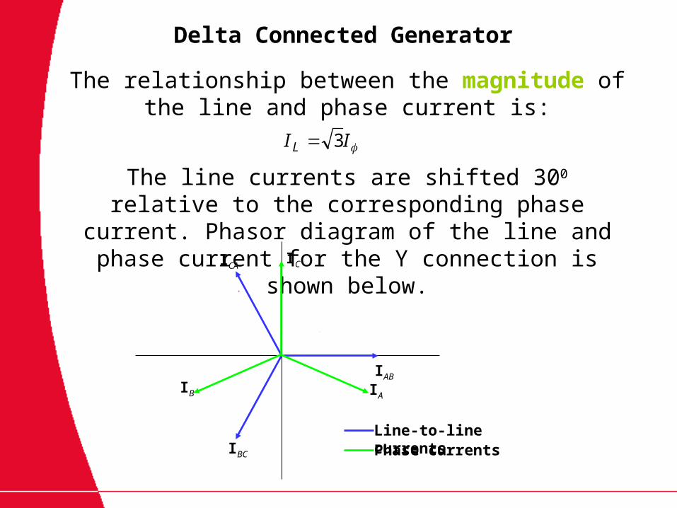
Delta Connected Generator
IIL 3
The relationship between the magnitude of the line and phase current is:
The line currents are shifted 300 relative to the corresponding phase current. Phasor diagram of the line and phase current for the Y connection is shown
below.
IA
IAB
IBC
IB
ICA
Line-to-line currentsPhase currents
IC
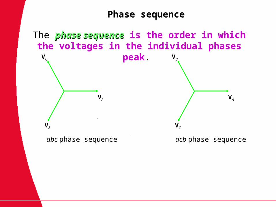
Phase sequence
The phase sequencephase sequence is the order in which the voltages in the individual phases peak.
VA
VB
VC
VA
VC
VB
abc phase sequence acb phase sequence

Power relationship-phase quantities
The power equations applied to Y-or load in a balanced 3-phase system are:
cosIVP 3
sinIVQ 3
IVS 3
cosZIP 23
sinZIQ 23
ZIS 23
Real power
Unit=Watts(W)
Apparent power
Unit=Volt-Amps (VA)
Reactive power
Unit=Volt-Amps-Reactive (VAR)
- angle between voltage and current in any phase of the load
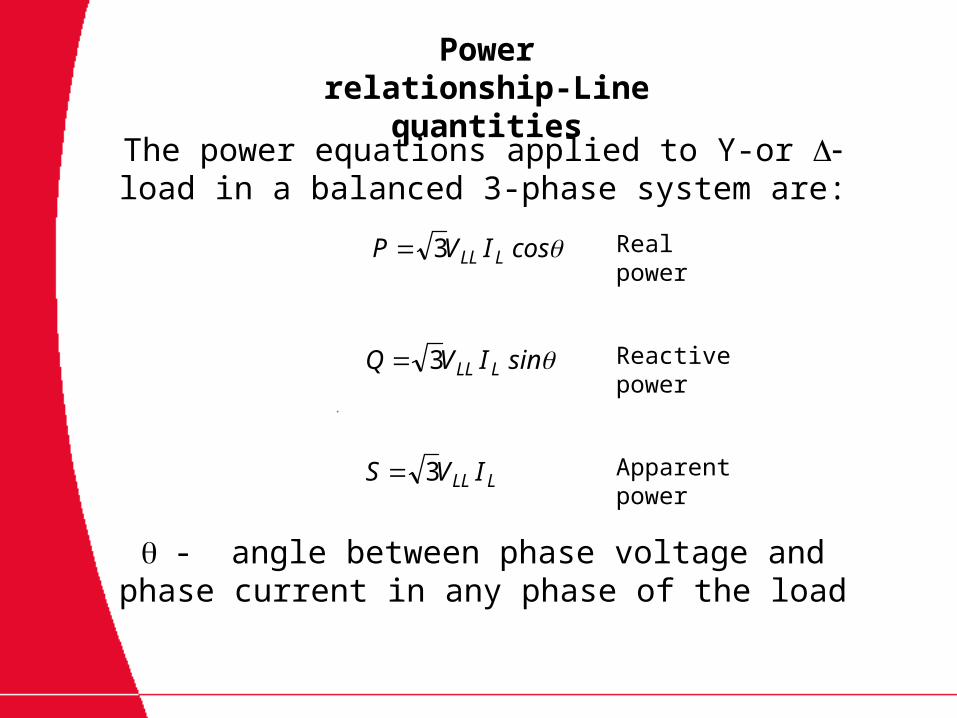
Power relationship-Line quantities
The power equations applied to Y-or load in a balanced 3-phase system are:
cosIVP LLL3
sinIVQ LLL3
LLL IVS 3
Real power
Apparent power
Reactive power
- angle between phase voltage and phase current in any phase of the load

Since both the three-phase source and the three-phase load can be either Y- or - connected, we
have 4 possible connections:
i) Y-Y connections (i.e: Y-connected source with a Y-connected load).
ii) Y- connection.
iii)- connection
iv)-Y connection
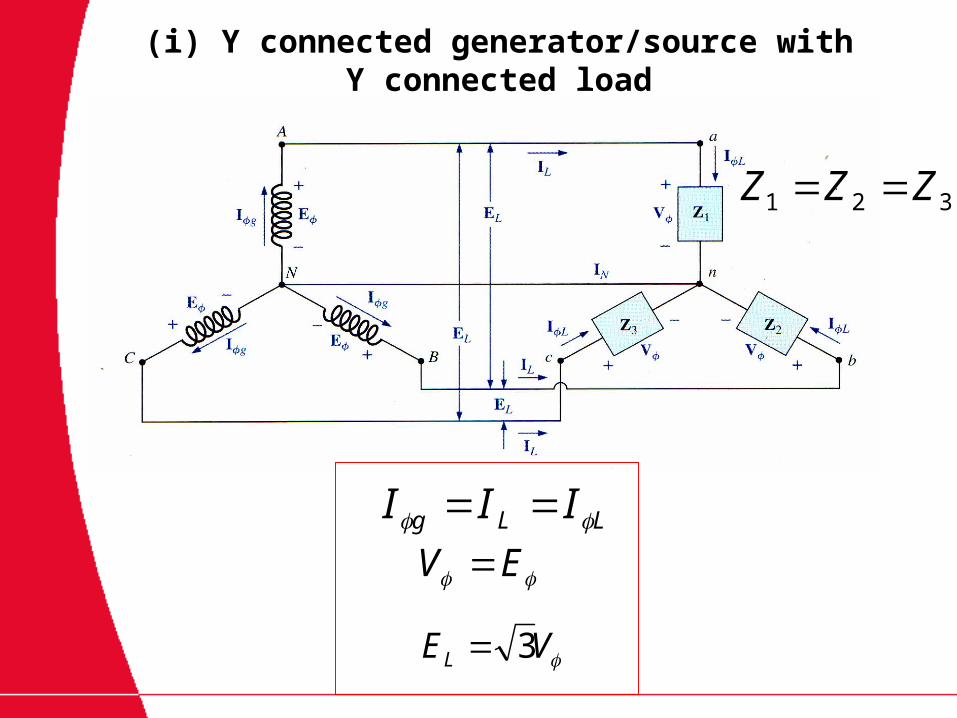
(i) Y connected generator/source with Y connected load
LLg III
EV
VEL 3
321 ZZZ
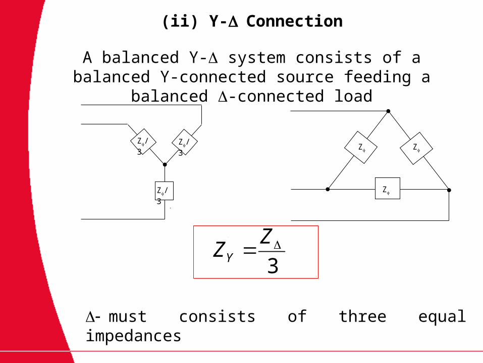
(ii) Y-Connection
3
ZZY
Z
Z
Z
Z/3
Z/3Z/3
must consists of three equal impedances
A balanced Y- system consists of a balanced Y-connected source feeding a balanced -connected load
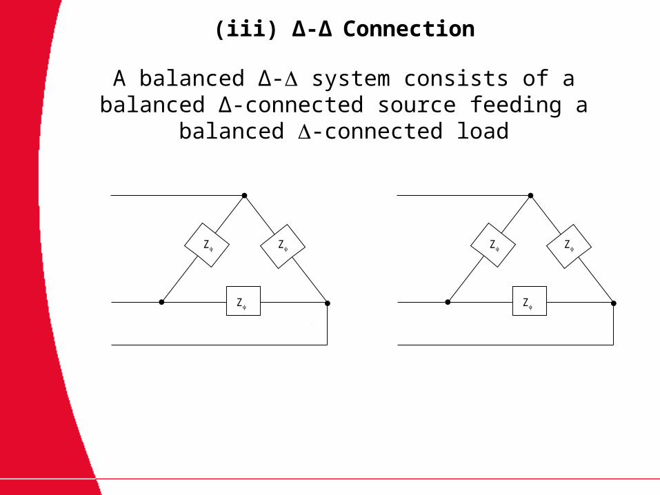
(iii) ∆-∆Connection
Z
Z
Z
A balanced ∆- system consists of a balanced ∆-connected source feeding a balanced -connected load
Z
Z
Z
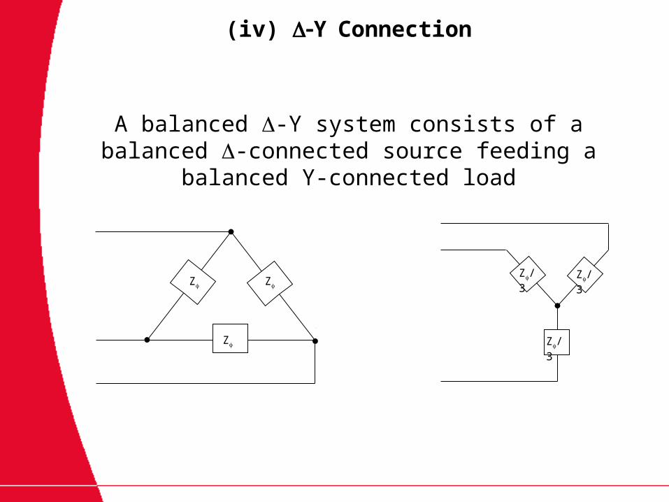
(iv) YConnection
Z/3
Z/3Z/3
A balanced -Y system consists of a balanced -connected source feeding a balanced Y-connected
load
Z
Z
Z
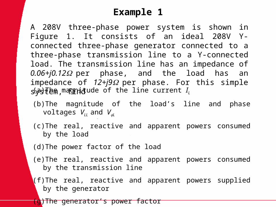
Example 1
A 208V three-phase power system is shown in Figure 1. It consists of an ideal 208V Y-connected three-phase generator connected to a three-phase transmission line to a Y-connected load. The transmission line has an impedance of 0.06+j0.12per phase, and the load has an impedance of 12+j9per phase. For this simple system, find
(a) The magnitude of the line current IL
(b) The magnitude of the load’s line and phase voltages VLL and VL
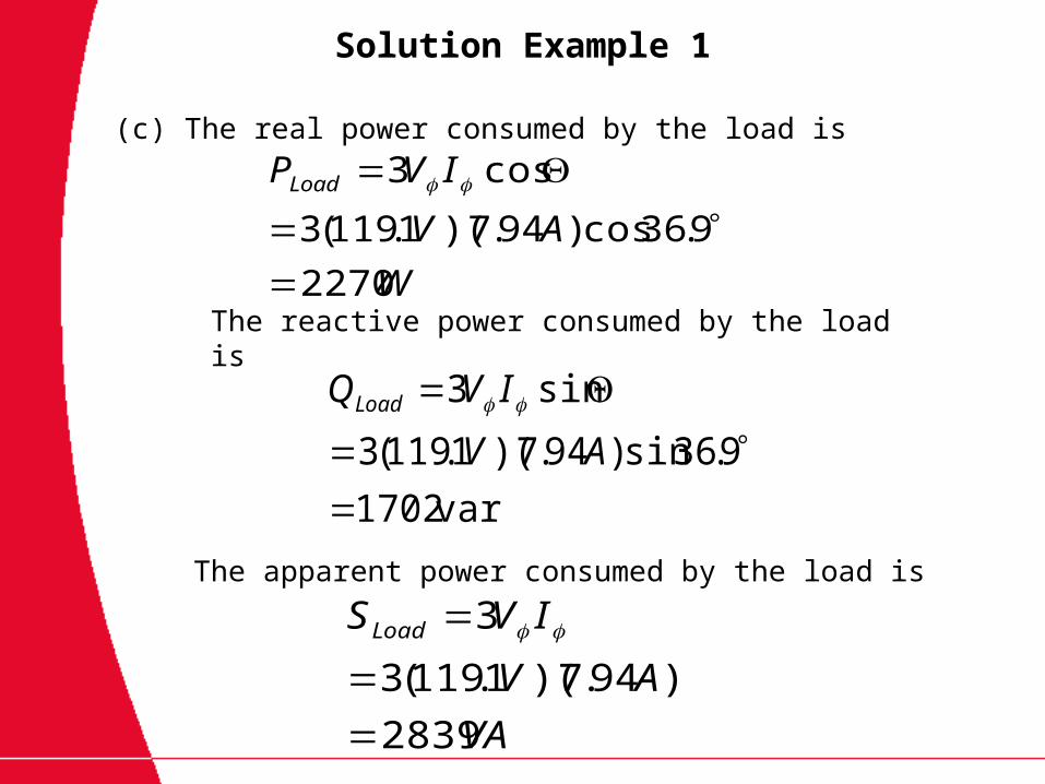
(c) The real, reactive and apparent powers consumed by the load
(d) The power factor of the load
(e) The real, reactive and apparent powers consumed by the transmission line
(f) The real, reactive and apparent powers supplied by the generator
(g) The generator’s power factor
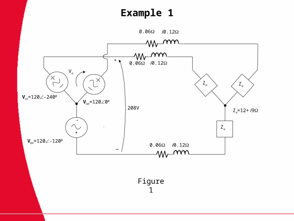
Example 1
Figure 1
Z
ZZ
Z=12+ i9
-
+
+
0.06
_
0.06
0.06
i0.12
i0.12
i0.12
V
Van=12000
Vbn=120-1200
Vcn=120-2400
208V

Solution Example 1
(a)The magnitude of the line current IL
A
j
jj
V
ZZ
VI
loadline
lineline
1.3794.7
1.3712.15
0120
12.906.12
0120
)912()12.006.0(
0120
So, the magnitude of the line current is thus 7.94 A
Solution Example 1
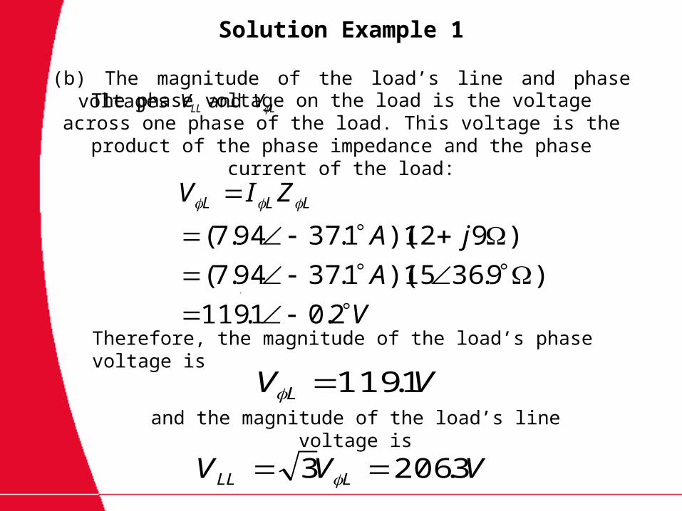
(b) The magnitude of the load’s line and phase voltages VLL and VL
V
A
jA
ZIV LLL
2.01.119
)9.3615)(1.3794.7(
)912)(1.3794.7(
VV L 1.119
VVV LLL 3.2063
The phase voltage on the load is the voltage across one phase of the load. This voltage is the product of the phase impedance and
the phase current of the load:
Therefore, the magnitude of the load’s phase voltage is
and the magnitude of the load’s line voltage is
Solution Example 1
W
AV
IVPLoad
2270
9.36cos)94.7)(1.119(3
cos3
var1702
9.36sin)94.7)(1.119(3
sin3
AV
IVQLoad
VA
AV
IVSLoad
2839
)94.7)(1.119(3
3
(c) The real power consumed by the load is
The reactive power consumed by the load is
The apparent power consumed by the load is
Solution Example 1
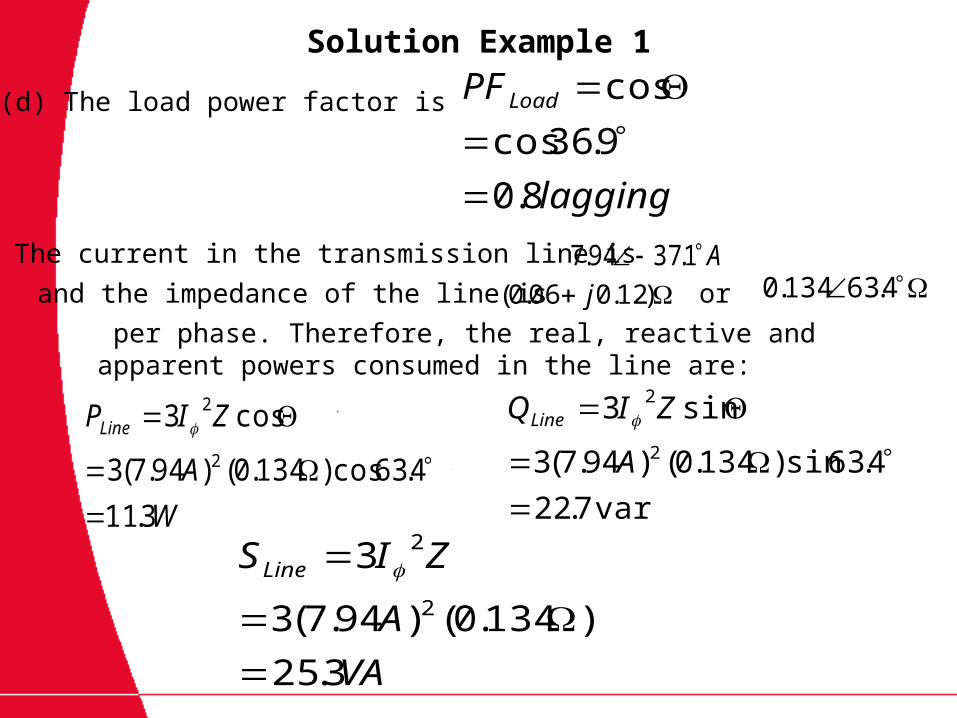
(d) The load power factor is
lagging
PFLoad
8.0
9.36cos
cos
A 1.3794.7 )12.006.0( j 4.63134.0
W
A
ZIPLine
3.11
4.63cos)134.0()94.7(3
cos32
2
var7.22
4.63sin)134.0()94.7(3
sin32
2
A
ZIQLine
VA
A
ZISLine
3.25
)134.0()94.7(3
32
2
(e) The current in the transmission line is
and the impedance of the line is or
per phase. Therefore, the real, reactive and apparent powers consumed in the line are:
Solution Example 1
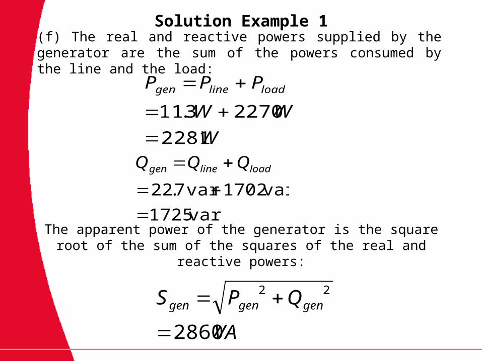
W
WW
PPP loadlinegen
2281
22703.11
var1725
var1702var7.22
loadlinegen QQQ
VA
QPS gengengen
2860
22
(f) The real and reactive powers supplied by the generator are the sum of the powers consumed by the line and the load:
The apparent power of the generator is the square root of the sum of the squares of the real and reactive powers:
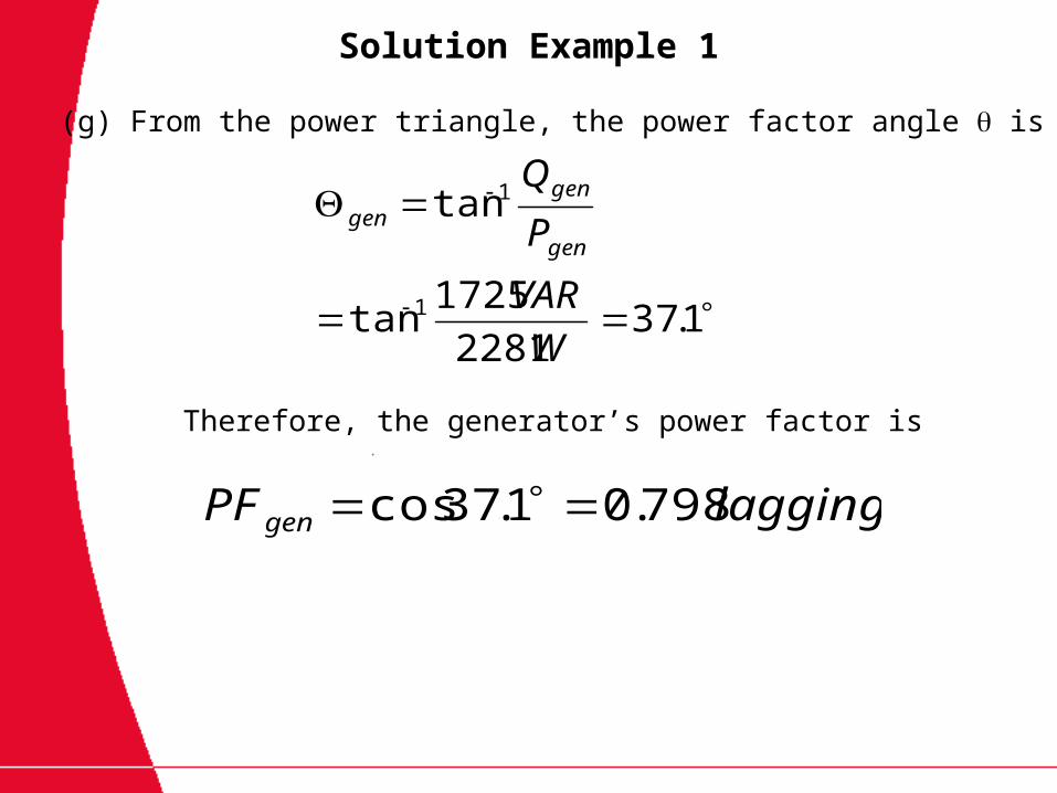
Solution Example 1
1.372281
1725tan
tan
1
1
W
VAR
P
Q
gen
gengen
laggingPFgen 798.01.37cos
(g) From the power triangle, the power factor angle is
Therefore, the generator’s power factor is

Assignment 2
A 208V three-phase power system is shown in Figure 2. It consists of an ideal 208V Y-connected three-phase generator connected to a three-phase transmission line to a -connected load. The transmission line has an impedance of 0.06+j0.12per phase, and the load has an impedance of 12+j9per phase. For this simple system, find
(a) The magnitude of the line current IL
(b) The magnitude of the load’s line and phase voltages VLL and VL
(c) The real, reactive and apparent powers consumed by the load
(d) The power factor of the load
(e) The real, reactive and apparent powers consumed by the transmission line
(f) The real, reactive and apparent powers supplied by the generator
(g) The generator’s power factor
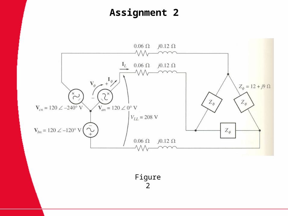
Assignment 2
Figure 2