basic physics of ultrasound beth baughman dupree m.d. facs medical director breast health program...
TRANSCRIPT

Basic Physics of Ultrasound
Beth Baughman DuPree M.D. FACS
Medical Director Breast Health Program Holy Redeemer Health System
2011
Financial Disclosures
Faculty/Consultant Ethicon Breast Care Speaker- Myriad Genetics Consultant Precision Therapeutics Faculty- CME at Sea

Breast Ultrasound CertificationStereotactic Biopsy CertificationMastery of Surgery ProgramAPBI Registrywww.breastsurgeons.org

The Changing World of Breast Care
1980 1990 2000 2010
MR Mastectomy BCT DCIS
BCT Lump/ALND XRT DCIS
CHEMO N - SLN BLN
ONCOTYPE
APBI B-39
STEREO MIBB
US MIBB
CONSENSOUS ST
MRI MIBB
OPEN SURGICAL BX
WHOLE BREAST XRT PEM BX
BRCA TESTING
Precision Therapeutics Chemo Fx Assay


Basic Principles
Sound waves are mechanical waves that require a medium through which to propagate
Sound cannot travel through a vacuum Different materials have different acoustic properties
Varies the ability to transmit sound waves Varies the ability to reflect sound at interfaces


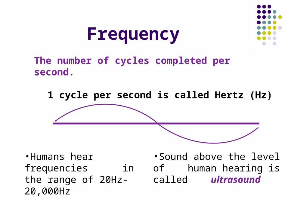
Frequency
The number of cycles completed per second.
1 cycle per second is called Hertz (Hz)
•Humans hear frequencies in the range of 20Hz-20,000Hz
•Sound above the level of human hearing is called ultrasound
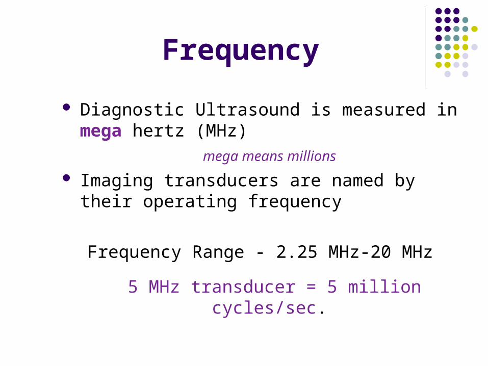
Frequency
Diagnostic Ultrasound is measured in mega hertz (MHz)
mega means millions
Imaging transducers are named by their operating frequency
Frequency Range - 2.25 MHz-20 MHz
5 MHz transducer = 5 million cycles/sec.
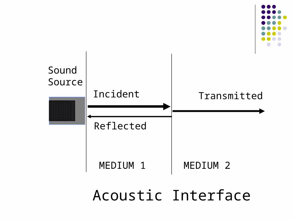
SoundSource
Incident
Reflected
Transmitted
MEDIUM 1 MEDIUM 2
Acoustic Interface
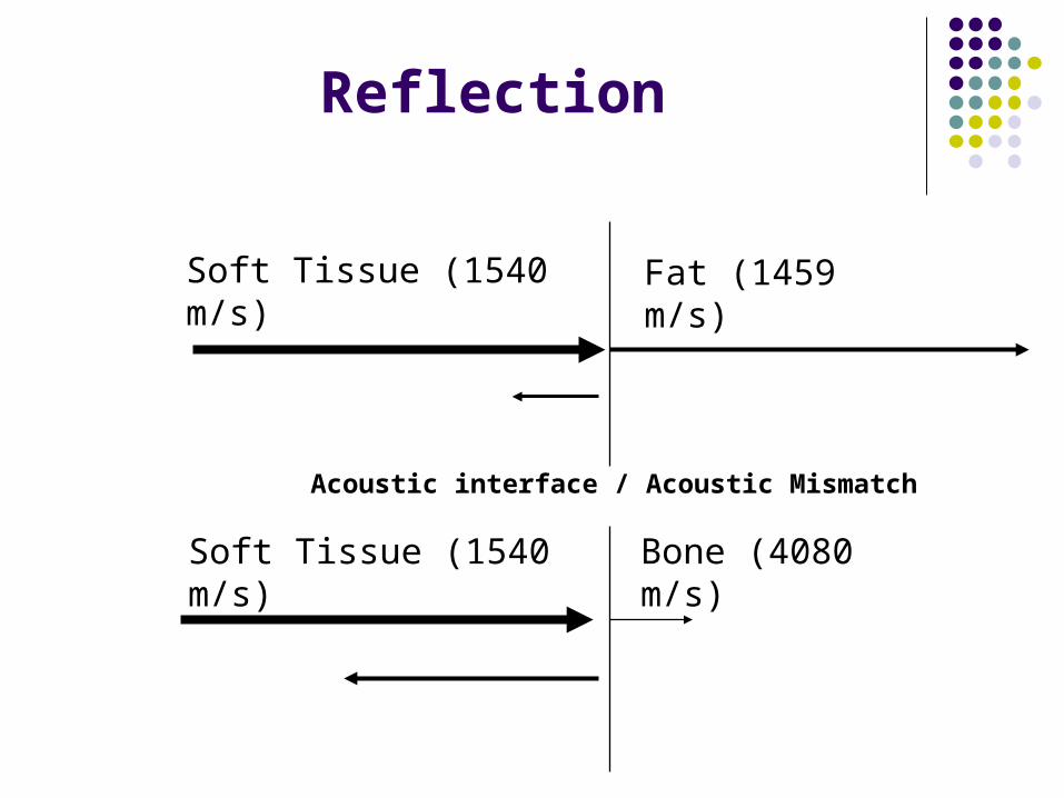
Reflection
Soft Tissue (1540 m/s) Fat (1459 m/s)
Bone (4080 m/s)Soft Tissue (1540 m/s)
Acoustic interface / Acoustic Mismatch

Getting an Image
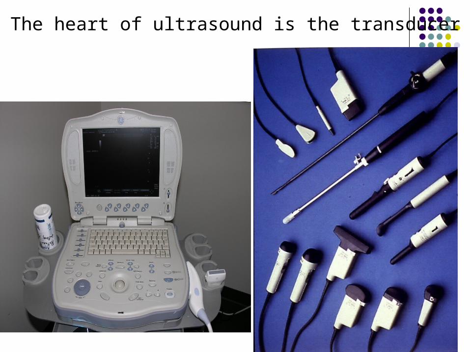
The heart of ultrasound is the transducer
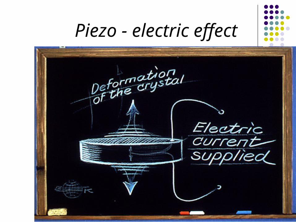
Piezo - electric effect

Piezo-Electric Effect
The crystal is mounted on a rotational axis It is driven by an electric motor A sound pulse is transmitted and received Results in a specific focal zone Some transducers contain several crystals Hence 8-14mHz probes have several crystals
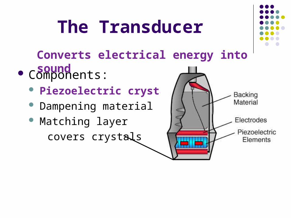
The Transducer
Components: Piezoelectric crystal Dampening material Matching layer
covers crystals
Converts electrical energy into sound
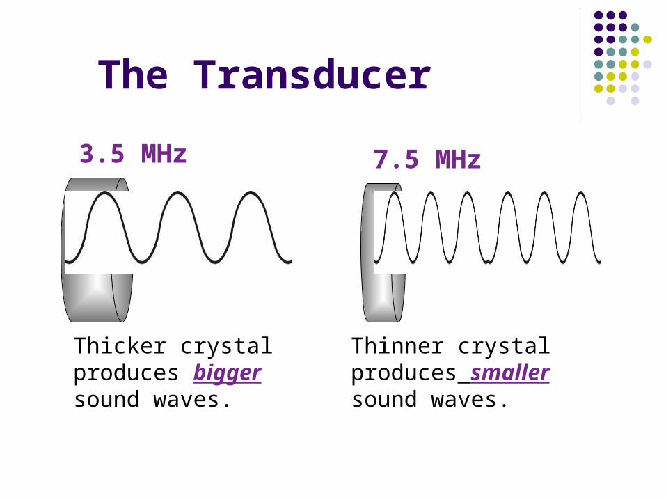
7.5 MHz3.5 MHz
Thinner crystal produces smaller sound waves.
The Transducer
Thicker crystal produces bigger sound waves.

The Transducer
The LOWER the frequency the better the penetration
Bigger, Stronger
The HIGHER frequency the less the penetration
Smaller, weaker
3.5 MHz 7.5 MHz
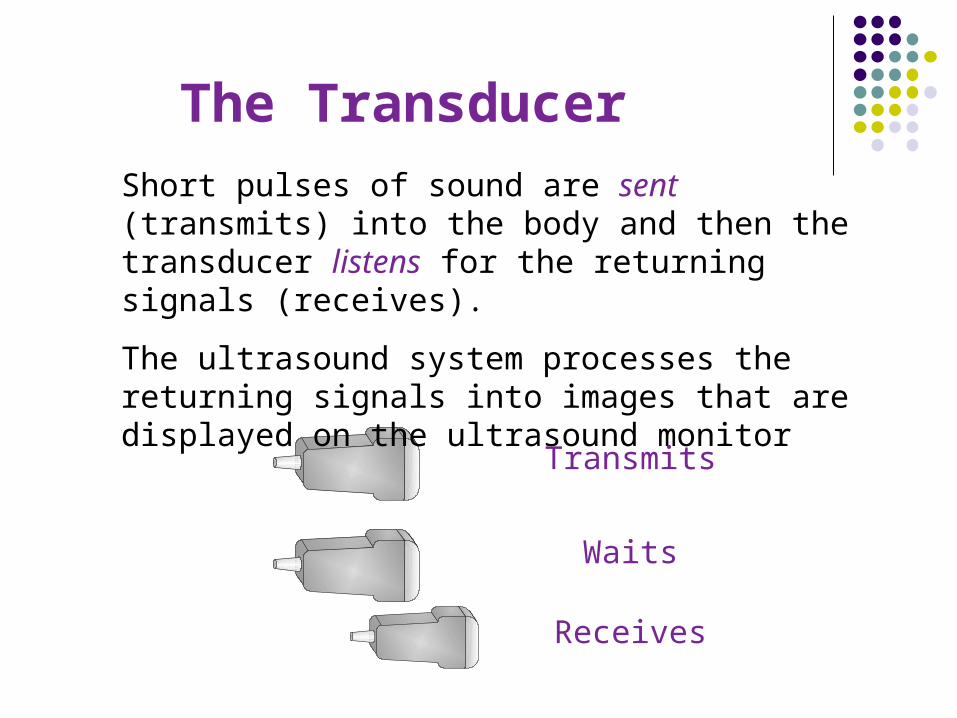
The Transducer Short pulses of sound are sent (transmits) into the body and then the transducer listens for the returning signals (receives).
The ultrasound system processes the returning signals into images that are displayed on the ultrasound monitor
Transmits
Waits
Receives

Linear Array Transducer

Electronic Linear-Array Transducer
Parallel arrangement of the crystals Two-dimensional, rectangular image
Time delay between successive crystal firing can be varied Directing and focusing the beam

B-Mode Ultrasound
Soft Tissue
Soft Tissue
Soft Tissue
Fat
Bone
Cyst
Gray Scale
Grayscale Imaging
Propagation speed is how fast the sound travels through a medium.
The system keeps track of when the pulse is sent and when the
echo returns and places the pixel at a depth represented by the
time difference.
The system keeps track of when the pulse is sent and when the
echo returns and places the pixel at a depth represented by the
time difference.

The strength of the returning echoes also depends on the differences in the acoustic impedance between various structures.
Acoustic impedance relates to tissue density.
The greater the difference in density between two structures, the stronger the returning echo
Examples:
different: aorta and liver
same: kidney and liver
Grayscale Imaging
Attenuation: A decrease in the strength of the sound wave as it passes through tissue and further into the body.
Acoustic Impedance:
The resistance of the sound wave traveling through tissue
Each tissue has its own acoustic impedance due to the density of the tissue.
Through Transmission
There is no attenuation of the sound wave traveling through the tissue.
Grayscale Imaging

WHITE DOTS = STRONG = e.g., bone
BLACK DOTS = NO reflections = e.g., fluid
GRAY (different shades) = WEAKER reflections
Grayscale Imaging

The strength of the returning echo is directly related to the angle at
which the ultrasound beam strikes an interface.
Grayscale Imaging
The more perpendicular the ultrasound beam, the
stronger the returning echo.
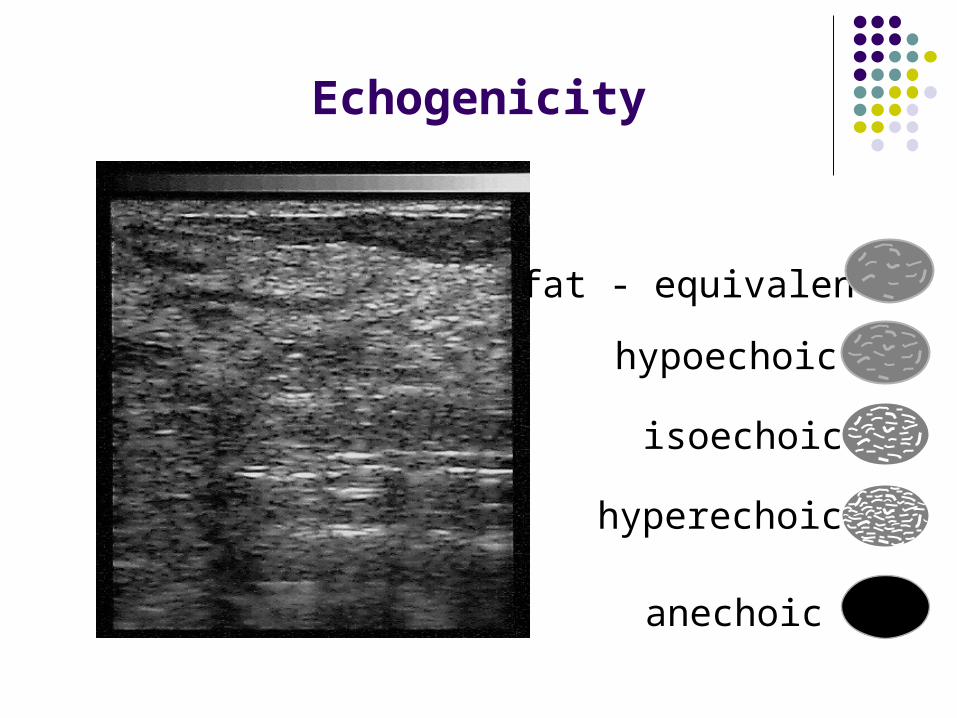
Echogenicity
hypoechoic
fat - equivalent
isoechoic
hyperechoic
anechoic

Echogenicity
Anechoic Hypoechoic Isoechoic Hyperechoic

Echogenicity
Anechoic Hypoechoic Isoechoic Hyperechoic

Echogenicity
Anechoic Hypoechoic Isoechoic Hyperechoic

Echogenicity
Anechoic Hypoechoic Isoechoic Hyperechoic

Resolution
Clarity of picture
Ability of equipment to detect 2 separate reflectors in tissue and to display them as 2 separate reflectors on the monitor without merging them.

Image Resolution
Types of Resolution
The ability to identify structures very close together:
Axial Ability to identify structures that are one in front of the other
Lateral Ability to identify structures that are side by side
Temporal Ability to accurately locate a moving structure
Spatial Ability to display very small structures in their correct anatomic location.
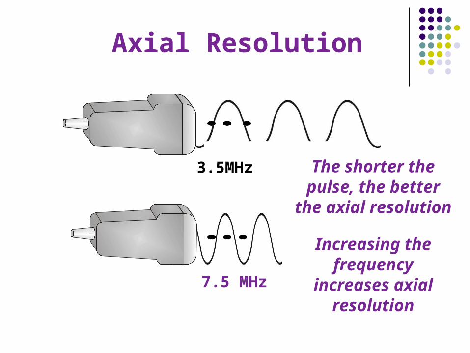
3.5MHz
7.5 MHz
Axial Resolution
The shorter the pulse, the better
the axial resolution
Increasing the frequency
increases axial resolution
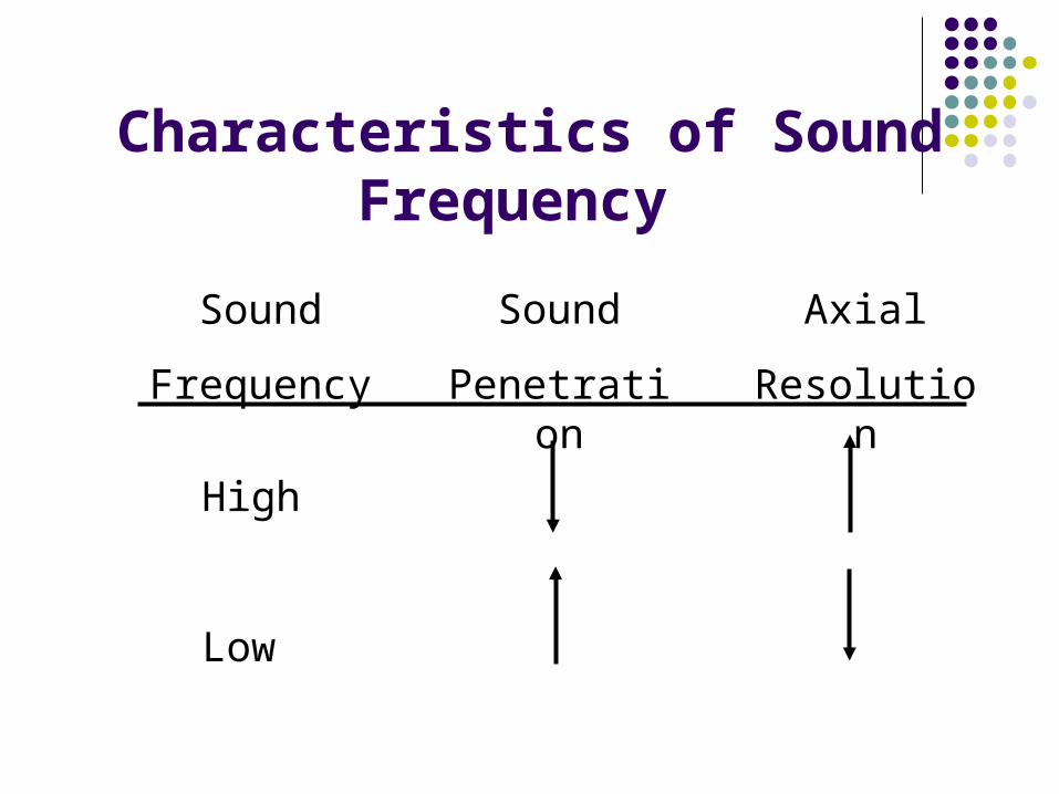
Characteristics of Sound Frequency
Sound
Frequency
Sound
Penetration
Axial
Resolution
High
Low

A transducer with a large surface area will resolve better in the
lateral dimension
Very important for ultrasound guidance with needles/probes
Lateral Resolution

“Fine-tuning” the Image

Gain=Volume

GAIN Control
Controls the brightness of the whole image

Not enough gain Too much gain

Time Gain Compensation (TGC) Depth Gain Compensation
• Compensates for tissue attenuation
• Controls the brightness in portions of the image
• Distributed over depth
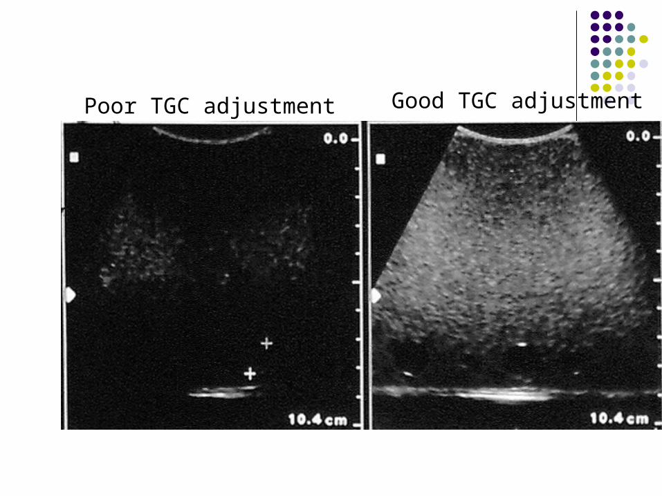
Poor TGC adjustment Good TGC adjustment

Focus

Focal Zones• Decreases the beam diameter
• Adjustable by operator.
• Place in area of interest
Focus the Image

Focal Zones
Image of a solid mass with the focal zone placed incorrectly
The focal zone depicted by the caret is at the bottom of the image.

Focal Zones
Image of the same solid mass with the focal zone placed correctly
The focal zone depicted by the caret is at the top of the image near the lesion.

Depth Depth is patient dependant Depth is transducer
dependant Operator controlled Deep
Increase depth Demonstrate shadowing
Superficial Decrease depth

Image Artifacts
Acoustic Shadowing
Acoustic Enhancement
Used to decide if structures are fluid-filled, solid or a combination.
Acoustic Shadow = decrease in the intensity of the echoes behind the attenuating structure
Acoustic Enhancement = increase in the intensity of the echoes behind the structure

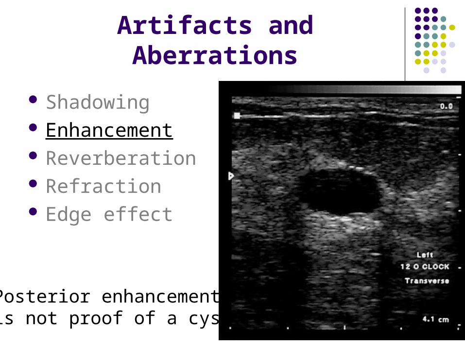
Artifacts and Aberrations
Shadowing Enhancement Reverberation Edge effect

Shadowing
Artifacts and Aberrations
Shadowing Enhancement Reverberation Refraction Edge effect
Posterior enhancementis not proof of a cyst.

Artifacts and Aberrations
Shadowing Enhancement Reverberation Refraction Edge effect

First Reflector
Second Reflector
Reverberation

Artifacts and Aberrations
Shadowing Enhancement Reverberation Refraction Edge effect
IncidentBeam Reflected
Beam
TransmittedBeam
Medium 1Medium 2
Snell’s Law

Artifacts and Aberrations
Shadowing Enhancement Reverberation Refraction Edge effect

S
C
B
R
Edge effect
Summary of Ultrasound Physics
Frequency-”resolution”
Gain-”volume”
Focus-”beam adjustment”
Depth-”field of view”
