basic steps for installing the ameriglide express dumbwaiter · remove shipping bracket from top of...
TRANSCRIPT

©2018 AmeriGlide
1. Remove Shroud.
2. Mount lower section of Track and Unit to hoistway wall andBrackets.
3. Remove Shipping Bracket from Top of Car.
4. Install other track pieces and brackets.
5. Set Header on top end of Track and attach Steel Cable.
6. Make wiring connections at Header.
7. Run lift in up direction (using temporary pendant control) towind the steel cable onto the drum.
8. Mount Cams on Track.
9. Install Interlocks.
10.Test in Automatic Operation
11. Attach Header Cover and Shroud.
Note:AmeriGlide lifts meet the stringent requirements of ASME A17.1, and ASME A18.1 when installed properly. Please check with local authorities to assure local code compliance, installation requirements, and to determine if permits are required.
Save these instructions.
630-00093- Rev. A
Basic steps for installing the AmeriGlide Express Dumbwaiter
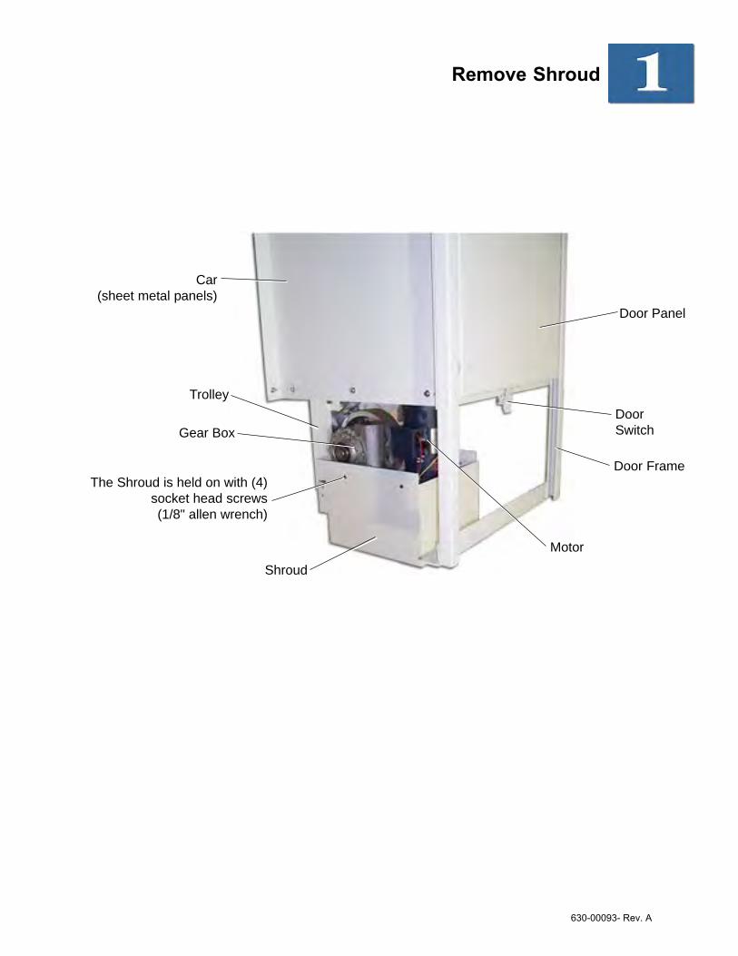
Remove Shroud
The Shroud is held on with (4)socket head screws(1/8" allen wrench)
Shroud
Car(sheet metal panels)
Trolley
Gear Box
Door Frame
DoorSwitch
Door Panel
Motor
630-00093- Rev. A

Stand Unit with Track in Hoistway and attach to wall
Bracket attaches to trackwith 3/8-16 x 3/8" hex headscrew and a square nut(inside slot of track)
Tip: The square nuts are heldinside the track slots withpieces of foam, do notremove the pieces of foamuntil installation is complete.
Attach to wall with #14 x 2"wood screws
Bracket Locations:-6" from each end of track-12" from each side of track splice
Note: In some applications it may benecessary to remove the carfrom the trolley.
Stand the assembly up and intoplace inside the hoistway(consult the application drawing forproper placement).
Square Nut
630-00093- Rev. A

Remove Shipping Bracket from top of Car
The Shipping Bracket is used tohold the car in place duringshipment. Remove and discardthe bracket
ImportantUncoil the Steel Drive Cable and TravelCable, ensuring they are not twisted.
Remove Shipping Wire Tiesholding the Steel Drive Cable
and Travel Cable together
Steel Drive Cable
Travel Cable
630-00093- Rev. A

Install Other Track Pieces and Brackets
Splice Bar
Set Screw
Each piece of Track has 4 SpliceBars installed in the lower end.Loosen the set screws (5/32"allen wrench) and slide the barshalf way out and re-tighten theset screws.
Slide the Track andSplice Bars into the
Track mounted tothe wall
Tighten all set screwswhen the track joint is
properly aligned Attach the trackto the wall withtrack brackets
(continued on next page)
Match track piecesto the correspondingletter(A to A, B to B)
630-00093- Rev. A

Install Other Track Pieces and Bracketscontinued
For 3-Stop Dumbwaiters only:
The sliding cam should contact the car top switch when the car isat the middle landing. Final adjustment can be made after themiddle landing cam is adjusted.
The sliding cam rides along with the car when the car is at orabove the middle landing stop.
The switch tells the controller which direction to run when amiddle ‘call’ is registered.
Sliding Cam
Insert Sliding Caminto slot of Track
Sliding Cam Stop-Loosen screw to
adjust to proper height
630-00093- Rev. A

Set Header on top of Track and attach Steel Cable
Secure Steel Cable with aclevis pin and cotter pin
Header sets ontop of the track
(It is not mechanicallyfastened to the track)
Tapped screw holesare for attaching the
Header Cover later inthe Installation
Insert end of SteelCable into Header
The Travel Cableruns down this
side of the Track
Secure Travel Cable insidethe Track (above blackplastic chain) with adhesiveclips. (adhesive goesagainst side wall of track)Space clips approximately24” between the plasticchain and track header
630-00093- Rev. A

Make Wiring Connections at Header
115 VAC 15 ampPower Connection
1. Connect to power.2. Plug-in Call-Send cables.3. Plug-in Interlock cables
HeaderRoute wiresthough theknockouts inthe header
Call-Send Cables-Connectors are the same.
-Cables are supplied in differentlengths. The shortest cablegoes to the upper floor, etc. Interlock Cables
-see notes below
Plug into matingconnectors
Wires from Travel Cable
Upper Interlock
Middle Interlock(3-Stops only)
Lower Interlock
Interlock Cable Note:The connectors for the interlocks aredifferent to prevent being plugged intothe wrong interlock.
The photo to the right shows the orienta-tion of the connectors at the header.
630-00093- Rev. A

Run lift in the up direction (usingtemporary pendant control) towind the steel cable onto thedrum
The cable should be wound onto thegrooves of the drum. Ensure that nogrooves are skipped or that the cabledoes not wind over itself.
Warning!All Safety Devices (except for the finallimit) are bypassed when using the pen-dant control.
Temporary Pendant Control
Wind the Steel Cable onto the Cable Drum
Cable Drum rotates thisdirection in when running UP
630-00093- Rev. A

Mount Cams on Track
Upper LimitCam
Notes:• Bottom of the floor limit cams are located approximately 15" below the landing stop.• Cams can be moved up or down to adjust the stopping position of the car.• Switches are located on the car.• The final limit is a safety that stops the operation of the dumbwaiter if the car should overrun the upper or
lower limit. It disables all controls when actuated.
Upper Limit Cam
Lower Limit Cam
Middle Limit Cam
Sliding Cam(installed in step 4)
48 3/4"
Track
Track
Layout for 2-Stop Layout for 3-Stop
Upper LimitCam
Cam attaches to athreaded ‘nut bar’ insidethe slot of the Track (nutbar is held in place bypieces of foam)
Lower Limit Cam
Final LimitCam
Final Limit Cam
Final LimitCam
Final LimitCam
Final Limit Cam
630-00093- Rev. A
Install G.A.L. Interlocks
The G.A.L. interlock prevents the dumbwaiter fromoperating if a hoistway door is opened. The hoistwaydoor is unlocked mechanically when a cam on the carcontacts a lever arm on the interlock.
(continued on next page)
The Interlock will belocated in the uppercorner of the door-way, opposite of thedoor hinges
Rod goes throughDoor Jamb(may be trimmed ifnecessary)
Actuator Arm/Roller(makes contact with angled cam on car)
Interlock mounts toDoor Jamb in 2 places
Wires routethrough hole in top
Emergency Release(drill hole through door
face for access)
Face of Interlock to be located 7/16" off of the insideof the ‘closed’ hoistway door
Cut-out hoistway wall asnecessary to accommo-
date Actuator Arm
View of Backside of Interlock
630-00093- Rev. A

Install G.A.L. Interlockscontinued
Notes:• If doors are not installed at the time of the dumbwaiter installation, the door closed switch can be bypassed
by twisting wires #1 and #2 together.
WARNING: Only when necessary, this safety circuit should only be bypassed during installation or trouble-shooting. The dumbwaiter should never be allowed to be used under any circumstances with a disabledsafety device by anyone other than a person that is servicing it whom has the knowledge of the functionalityof this safety. Possible risk of injury or death could occur if the safety circuit is bypassed or not functioningproperly.
WARNING: If at any time the interlock is found not to be working properly, the lift should immediately betaken out of service until repairs can be made. Failure to do so could lead to the possible risk of injury ordeath.
Route the Interlock Cable thru holein top of Interlock and connect wires#1 and #2 to the terminal block andthe green wire to ground
Attach the Keeper to the inside ofthe hoistway door in alignment withthe Interlock
The Cam on the Car canbe adjusted vertically andhorizontally
The angle of the Actuator Armcan be adjusted for proper
actuation of the Interlock
630-00093- Rev. A

Test in Automatic Operation
The car door(s) and hoistway doors must be closed for thedumbwaiter to run
Test the following items to confirm proper setup of thedumbwaiter:
Verify each call-send control ‘calls’ and ‘sends’ thedumbwaiter to the appropriate landing.
Verify the floor of the dumbwaiter stops level with thesill at each stop. Adjust position of cams if necessary.
Verify all controls are inoperable if the car door is open.
Verify all controls are inoperable if a hoistway door isopen. Test each hoistway door individually.
Verify each hoistway door locks when the dumbwaitercar is not parked at that landing.
Verify all controls are inoperable if the final limit switchis actuated.
Verify all controls are inoperable if the slack cabledevice switch is opened.
Travel Cable: Verify that the travel cable properlytravels inside the track and adhesive clips are properlyinstalled.
Hardware: Verify all track mounting hardware, switchcams and car hardware are securely tightened.
630-00093- Rev. A

Complete the Installation
1. Install cover on header.
2. Replace shroud.
3. Use a permanent marker to mark the installationdate on the data plate.
630-00093- Rev. A

1 1
2 2
3 3
4 4
AA
BB
SH
EET
1O
F1
DRAW
N
CH
ECKED
JB7/3
0/2
010
DW
GN
O
25472
TIT
LE
SIZ
E
BSCALE
REV
B
1850
5E
.163
rdS
t.La
keW
inne
bago
,MO
6403
481
6-53
7-06
11
This
docu
ment
is t
he p
ropert
y o
f Am
eriG
lide
and is
deliv
ere
d u
pon t
he e
xpre
ss c
onditio
n t
hat
the
conte
nts
will
not
be d
iscl
ose
d o
r use
d w
ithout
the
writt
en c
onsc
ent
of
Amer
iGlid
e.
Tole
rance
UN
O.X .X
X.X
XX
Hole
sAng
±.1
±.0
1±
.005
±.0
05
±.5
°
FIN
ISH
TH
IRD
AN
GLE
PRO
JECTIO
N
ASSY,Sub,3-S
top
Sw
itch
Pla
te
PAR
TS
LIS
T DESCR
IPTIO
NPART
#Q
TY
ITEM
Pla
te,Lim
itSw
itch
25016P
11
Sw
itch
,Lim
itw
ith
Rolle
r16014
42
Set
Scr
ew
,Cup
Pt,
1/4
-20
x3/4
"10035
23
Scr
ew
,PH
-RH
-MS,
6-3
2x3
"10205
24
Scr
ew
,R
H-P
H-M
S,
6-3
2x
1.2
5"
10019
25
Lock
Nut,
Nylo
n,
6-3
210009
46
Wash
er,
Fla
t,#
6,ZP
10207
27
Encl
osu
re,Term
inal,
Mach
ined
16194M
18
Wire
ASSY,XForm
er
Pow
er,
White
(not
show
n)
24011
19
Wire
ASSY,F
inalLim
it(n
ot
show
n)
24062
110
REVIS
ION
HIS
TO
RY
REV
ECN
DESCR
IPTIO
NBY
DATE
B280
Change
HD
Wfo
rTerm
inalEncl
osu
reJB
02/2
9/0
8
26
51
47
8
3
MiddleLimit
BottomLimit
TopLimit
FinalLimit
630-00093- Rev. A

QA-000116 Rev A
IMPORTANT SAFETY INSTRUCTIONS Please Post Instructions
WARNING
When service or maintenance is required on this dumbwaiter the following precautions shall be followed:
Disconnect - main power supply from the dumbwaiter using appropriateLOTO-T methodologies
Do Not - override door interlocks (aka “jump out”)
Do Not - override machine access door switch
Do Not - come in contact with moving parts
DO NOT ENTER HOISTWAY – access only through machine access door.Verify if local code requires Hoistway to be considered a confined space
Use – the Temporary Pendant Control to move the dumbwaiter inside thehoistway
WARNING: The safety circuit should only be bypassed during installation or
troubleshooting by a qualified technician who understands the functionality of the safety device. The dumbwaiter should never be allowed into operation with a disabled safety device. Possible risk of injury or death could occur if the safety circuit is bypassed or if it is not functioning properly.
WARNING: If the interlock is found not to be working properly, the dumbwaiter
should immediately be taken out of service until repairs can be made. Failure to do so has the potential to result in injury or death.
630-00093- Rev. A

QA-000116 Rev A
Access to the hoistway of the dumbwaiter
The Ascent dumbwaiter has a machine access door located below the lower landing door
Bottom view of dumbwaiter cab thru “machine access door” below the lower landing door
Machine Access Door 18” x 24”
To be normally locked and controlled by Safety Door Switch
Bottom side of
dumbwaiter cab
See instruction
manual for using
Temporary Pendant
Control
630-00093- Rev. A

QA-000116 Rev A
WARNING!All Safety Devices are bypassed when using the Temporary Pendant Control to move the dumbwaiter (except for the final limit). Final limit will stop the dumbwaiter at the top and the bottom of the rail. The bottom of the rail has a metal mechanical stop bolted on the rail below the lower limit cams. (It’s marked “DO NOT REMOVE”)
Temporary Pendant Control This allows the technician to use constant pressure controls
to move the dumbwaiter up or down during service / troubleshooting. This control can be made any length to allow a technician to operate the car from any location desired.
SERVICE & ACCESS TO CONTROLS (pertaining to troubleshooting)
The lift is designed with several features to allow safe troubleshooting by technicians.
Access for the temporary pendant control can be gained through the lower machine access door (ifthe lift at the lower landing) or though landing doors (if the lift is above the bottom landing).
A slack-rope device provides both mechanical and electrical safeties on the lift.
The slack-rope device can be reset from either below or above the car. Means of resetting include:o Pulling out on the suspension cable at a point above the car.o Manually turning the belt and pulleys at a point just under the car.o Running the lift in the up direction with the temporary control.
DO NOT ENTER HOISTWAY
630-00093- Rev. A