basic switch concepts and configuration -...
TRANSCRIPT

CHAPTER 2
Basic Switch Concepts and Configuration
Objectives
Upon completion of this chapter, you will be able to answer the following questions:
■ What are the principal Ethernet operations perti-nent to a 100/1000/10000 Mbps LAN in theIEEE 802.3 standard?
■ What are the functions that enable a switch toforward Ethernet frames in a LAN?
■ How do you configure a switch for operation ina network designed to support voice, video, anddata communication?
■ How do you configure basic security on a switchthat operates within a network designed to sup-port voice, video, and data communication?
Key Terms
This chapter uses the following key terms. You can find the definitions in the Glossary.
read-only memory (ROM) page 49
organizational unique identifier (OUI) page 49
half duplex page 49
full duplex page 49
auto-MDIX page 51
floods page 51
virtual LAN (VLAN) page 54
propagation delay page 54
store-and-forward page 59
cut-through switching page 59
GUI page 65
Simple Network Management Protocol (SNMP) page 65
non-volatile RAM (NVRAM) page 71
Trivial File Transfer Protocol (TFTP) page 80
encryption page 90
spoof page 100
Cisco Discovery Protocol (CDP) page 101
03_1587132079_ch02.qxd 3/27/08 2:33 PM Page 45

In this chapter, you build upon the skills learned in CCNA Exploration 4.0: NetworkFundamentals, reviewing and reinforcing these skills. You also learn about some key mali-cious threats to switches and learn to enable a switch with a secure initial configuration.
Introduction to Ethernet/802.3 LANs
In this section, you learn about key components of the Ethernet standard that play a signifi-cant role in the design and implementation of switched networks. You explore how Ethernetcommunications function and how switches play a role in the communication process.
Key Elements of Ethernet/802.3 Networks
Ethernet/802.3 networks rely on carrier sense multiple access/collision detect (CSMA/CD),unicast transmission, broadcast transmission, multicast transmission, duplex settings, switchport settings, and MAC address table management. We next review each of these conceptsfrom CCNA Exploration 4.0: Networking Fundamentals.
CSMA/CDEthernet signals are transmitted to every host connected to the LAN using a special set ofrules to determine which station can access the network. The set of rules that Ethernet usesis based on the IEEE carrier sense multiple access/collision detect (CSMA/CD) technology.Recall that CSMA/CD is used only with half-duplex communication typically found withhubs. Full-duplex ports do not use CSMA/CD.
In the CSMA/CD access method, all network devices that have messages to send must lis-ten before transmitting. If a device detects a signal from another device, it waits for a speci-fied amount of time before attempting to transmit. When there is no traffic detected, adevice transmits its message. While this transmission is occurring, the device continues tolisten for traffic or collisions on the LAN. After the message is sent, the device returns to itsdefault listening mode.
If the distance between devices is such that the latency of the signals of one device meansthat signals are not detected by a second device, the second device may also start to trans-mit. The media now has two devices transmitting signals at the same time. The messagespropagate across the media until they encounter each other. At that point, the signals mixand the messages are destroyed, a collision. Although the messages are corrupted, the jum-ble of remaining signals continues to propagate across the media.
When a device is in listening mode, it can detect when a collision occurs on the sharedmedia because all devices can detect an increase in the amplitude of the signal above thenormal level. When a collision occurs, the other devices in listening mode, as well as all thetransmitting devices, detect the increase in the signal amplitude. Every device that is trans-mitting continues to transmit to ensure that all devices on the network detect the collision.
46 LAN Switching and Wireless, CCNA Exploration Companion Guide
03_1587132079_ch02.qxd 3/27/08 2:33 PM Page 46

When a collision is detected, the transmitting devices send out a jamming signal. The jam-ming signal notifies the other devices of a collision so that they invoke a backoff algorithm.This backoff algorithm causes all devices to stop transmitting for a random amount of time,which allows the collision signals to subside.
After the delay has expired on a device, the device goes back into the “listening beforetransmit” mode. A random backoff period ensures that the devices that were involved in thecollision do not try to send traffic again at the same time, which would cause the wholeprocess to repeat. However, during the backoff period, a third device may transmit beforeeither of the two involved in the collision have a chance to retransmit.
Ethernet CommunicationsReference Figure 2-1 for the Ethernet communications discussion that follows. Communicationsin a switched LAN occur in three ways: unicast, broadcast, and multicast.
Figure 2-1 Ethernet Communications
Chapter 2: Basic Switch Concepts and Configuration 47
Unicast
Broadcast
Multicast
Client Group
With unicast communication, a frame is sent from one host and addressed to one specificdestination. In unicast transmission, there is just one sender and one receiver. Unicast trans-mission is the predominant form of transmission on LANs and within the Internet.Examples of unicast transmissions include HTTP, SMTP, FTP, and Telnet.
With broadcast communication, a frame is sent from one address to all other addresses. Inthis case, there is just one sender, but the information is sent to all connected receivers.Broadcast transmission is essential when sending the same message to all devices on theLAN. An example of a broadcast transmission is the address resolution query that theaddress resolution protocol (ARP) sends to all computers on a LAN.
03_1587132079_ch02.qxd 3/27/08 2:33 PM Page 47

With multicast communication, a frame is sent to a specific group of devices or clients.Multicast transmission clients must be members of a logical multicast group to receive theinformation. An example of multicast transmission is the video and voice transmissionsassociated with a network-based, collaborative business meeting.
To briefly review the Ethernet frame structure, recall that the Ethernet frame adds headersand trailers around the Layer 3 PDU to encapsulate the message being sent. Both theEthernet header and trailer have several sections (or fields) of information that are used bythe Ethernet protocol. Figure 2-2 shows the structure of the current Ethernet frame standard,the revised IEEE 802.3 (Ethernet).
Figure 2-2 Ethernet Frame
48 LAN Switching and Wireless, CCNA Exploration Companion Guide
7
Preamble
1
Start ofFrame
Delimiter
IEEE 802.3
6
DestinationAddress
6
SourceAddress
2
Length/Type
46 to 1500
802.2 Header andData
4
Frame CheckSequence
The Preamble (7 bytes) and Start Frame Delimiter (SFD) (1 byte) fields are used for syn-chronization between the sending and receiving devices. These first 8 bytes of the frame areused to get the attention of the receiving nodes. Essentially, the first few bytes tell thereceivers to get ready to receive a new frame.
The Destination MAC Address field (6 bytes) is the identifier for the intended recipient.This address is used by Layer 2 to assist a device in determining whether a frame isaddressed to it. The address in the frame is compared to the MAC address in the device. Ifthere is a match, the device accepts the frame.
The Source MAC Address field (6 bytes) identifies the frame’s originating NIC or interface.Switches use this address to add to their lookup tables.
The Length/Type field (2 bytes) defines the exact length of the frame’s data field. This fieldis used later as part of the Frame Check Sequence (FCS) to ensure that the message wasreceived properly. Only a frame length or a frame type can be entered here. If the purposeof the field is to designate a type, the Type field describes which protocol is implemented.When a node receives a frame and the Length/Type field designates a type, the node deter-mines which higher layer protocol is present. If the two-octet value is equal to or greaterthan 0x0600 hexadecimal or 1536 decimal, the contents of the Data Field are decodedaccording to the protocol indicated; if the two-byte value is less than 0x0600, the value rep-resents the length of the data in the frame.
The Data and Pad fields (46 to 1500 bytes) contain the encapsulated data from a higherlayer, which is a generic Layer 3 PDU, or more commonly, an IPv4 packet. All frames mustbe at least 64 bytes long (minimum length aides the detection of collisions). If a small packetis encapsulated, the Pad field is used to increase the size of the frame to the minimum size.
03_1587132079_ch02.qxd 3/27/08 2:33 PM Page 48

The FCS field (4 bytes) detects errors in a frame. It uses a cyclic redundancy check (CRC).The sending device includes the results of a CRC in the FCS field of the frame. The receiv-ing device receives the frame and generates a CRC to look for errors. If the calculationsmatch, no error has occurred. If the calculations do not match, the frame is dropped.
An Ethernet MAC address is a two-part 48-bit binary value expressed as 12 hexadecimaldigits. The address formats might be similar to 00-05-9A-3C-78-00, 00:05:9A:3C:78:00, or0005.9A3C.7800. All devices connected to an Ethernet LAN have MAC-addressed inter-faces. The NIC uses the MAC address to determine whether a message should be passed tothe upper layers for processing. The MAC address is permanently encoded into a read-onlymemory (ROM) chip on a NIC. This type of MAC address is referred to as a burned-inaddress (BIA). Some vendors allow local modification of the MAC address. The MACaddress is made up of the organizational unique identifier (OUI) and the vendor assign-ment number. The OUI is the first part of a MAC address. It is 24 bits long and identifiesthe manufacturer of the NIC card. The IEEE regulates the assignment of OUI numbers.Within the OUI are 2 bits that have meaning only when used in the destination address, thebroadcast or multicast bit and the locally administered address bit, shown in Figure 2-3.
Figure 2-3 OUI Composition
Chapter 2: Basic Switch Concepts and Configuration 49
Bro
adca
st
Loca
l
OUIVendor
Assigned
The broadcast or multicast bit in a MAC address indicates to the receiving interface that theframe is destined for all or a group of end stations on the LAN segment.
The locally administered address bit indicates whether the vendor-assigned MAC addresscan be modified locally.
The vendor-assigned part of the MAC address is 24 bits long and uniquely identifies theEthernet hardware. It can be a BIA or it can be modified by software indicated by the local bit.
Duplex SettingsThere are two types of duplex settings used for communications on an Ethernet network:half duplex and full duplex.
Half-duplex communication relies on unidirectional data flow where sending and receivingdata are not performed at the same time. This is similar to how walkie-talkies or two-wayradios function in that only one person can talk at any one time. If someone talks whilesomeone else is already speaking, a collision occurs. As a result, half-duplex communica-tion implements CSMA/CD to help reduce the potential for collisions and detect them whenthey do happen. Half-duplex communications have performance issues due to the constantwaiting, because data can flow in only one direction at a time. Half-duplex connections aretypically found in older hardware, such as hubs. Nodes that are attached to hubs that share
03_1587132079_ch02.qxd 3/27/08 2:33 PM Page 49

their connection to a switch port must operate in half-duplex mode because the end comput-ers must be able to detect collisions. Nodes can operate in a half-duplex mode if the NICcard cannot be configured for full-duplex operations. In this case, the port on the switchdefaults to a half-duplex mode as well. Because of these limitations, full-duplex communi-cation has replaced half-duplex in more current hardware.
In full-duplex communication, data flow is bidirectional, so data can be sent and received atthe same time. The bidirectional support enhances performance by reducing the wait timebetween transmissions. Most Ethernet, Fast Ethernet, and Gigabit Ethernet NICs sold todayoffer full-duplex capability. In full-duplex mode, the collision-detect circuit is disabled.Frames sent by the two connected end nodes cannot collide because the end nodes use twoseparate circuits in the network cable. Each full-duplex connection uses only one port. Full-duplex connections require a switch that supports full duplex or a direct connection betweentwo nodes that each support full duplex. Nodes that are directly attached to a dedicatedswitch port with NICs that support full duplex should be connected to switch ports that areconfigured to operate in full-duplex mode.
Standard, shared hub-based Ethernet configuration efficiency is typically rated at 50 to 60 per-cent of the 10 Mbps bandwidth. Full-duplex Fast Ethernet, compared to 10 Mbps bandwidth,offers 100 percent efficiency in both directions (100 Mbps transmit and 100 Mbps receive).
Switch Port SettingsA port on a switch needs to be configured with duplex settings that match the media type.Later in this chapter, you will configure duplex settings. The Cisco Catalyst switches havethree settings:
■ The auto option sets autonegotiation of duplex mode. With autonegotiation enabled,the two ports communicate to decide the best mode of operation.
■ The full option sets full-duplex mode.
■ The half option sets half-duplex mode.
For Fast Ethernet and 10/100/1000 ports, the default is auto. For 100BASE-FX ports, thedefault is full. The 10/100/1000 ports operate in either half- or full-duplex mode when theyare set to 10 or 100 Mbps, but when set to 1,000 Mbps, they operate only in full-duplex mode.
Note
Autonegotiation can produce unpredictable results. By default, when autonegotiation fails, theCatalyst switch sets the corresponding switch port to half-duplex mode. This type of failure happenswhen an attached device does not support autonegotiation. If the device is manually configured tooperate in half-duplex mode, it matches the default mode of the switch. However, autonegotiationerrors can happen if the device is manually configured to operate in full-duplex mode. Having half-duplex on one end and full-duplex on the other causes late collision errors at the half-duplex end. Toavoid this situation, manually set the duplex parameters of the switch to match the attached device. Ifthe switch port is in full-duplex mode and the attached device is in half-duplex mode, check for FCSerrors on the switch full-duplex port.
50 LAN Switching and Wireless, CCNA Exploration Companion Guide
03_1587132079_ch02.qxd 3/27/08 2:33 PM Page 50

Additionally, you used to be required to use certain cable types (crossover, straight-through)when connecting between specific devices, switch-to-switch or switch-to-router. Instead,you can now use the mdix auto interface configuration command in the CLI to enable theautomatic medium-dependent interface crossover auto-MDIX feature.
When the auto-MDIX feature is enabled, the switch detects the required cable type for cop-per Ethernet connections and configures the interfaces accordingly. Therefore, you can useeither a crossover or a straight-through cable for connections to a copper 10/100/1000 porton the switch, regardless of the type of device on the other end of the connection.
The auto-MDIX feature is enabled by default on switches running Cisco IOS Release12.2(18)SE or later. For releases between Cisco IOS Release 12.1(14)EA1 and 12.2(18)SE,the auto-MDIX feature is disabled by default. It is enabled by default on Catalyst 2960 and3560 switches, but is not available as an option on Catalyst 2950 and 3550 switches.
Switch MAC Address TableSwitches use MAC addresses to direct network communications through their switch fabricto the appropriate port toward the destination node. The switch fabric is the integrated cir-cuits and the accompanying machine programming that allows the data paths through theswitch to be controlled. For a switch to know which port to use to transmit a unicast frame,it must first learn which nodes exist on each of its ports.
A switch determines how to handle incoming data frames by using its MAC address table.A switch builds its MAC address table by recording the MAC addresses of the nodes con-nected to each of its ports. After a MAC address for a specific node on a specific port isrecorded in the address table, the switch then knows to send traffic destined for that specificnode out the port mapped to that node for subsequent transmissions.
When an incoming data frame is received by a switch and the destination MAC address isnot in the table, the switch forwards the frame out all ports, except for the port on which itwas received. When the destination node responds, the switch records the node’s MACaddress in the address table from the frame’s source address field. In networks with multipleinterconnected switches, the MAC address tables record multiple MAC addresses for theports connecting the switches that reflect the nodes beyond. Typically, switch ports used tointerconnect two switches have multiple MAC addresses recorded in the MAC address table.
The following six steps describe the process used to populate the MAC address table on aswitch:
1. The switch receives a broadcast frame from PC1 on Port 1, as seen in Figure 2-4.
2. The switch enters the source MAC address and the switch port that received the frameinto the address table.
3. Because the destination address is a broadcast, the switch floods the frame to all ports,except the port on which it received the frame.
Chapter 2: Basic Switch Concepts and Configuration 51
03_1587132079_ch02.qxd 3/27/08 2:33 PM Page 51

Figure 2-4 MAC Address Table Population
52 LAN Switching and Wireless, CCNA Exploration Companion Guide
PC11 3
2
PC2
FRAME
4. The destination device replies to the broadcast with a unicast frame addressed to PC1.
5. The switch enters the source MAC address of PC2 and the port number of the switchport that received the frame into the address table. The destination address of the frameand its associated port are found in the MAC address table.
6. The switch can now forward frames between source and destination devices withoutflooding, because it has entries in the address table that identify the associated ports.
Design Considerations for Ethernet/802.3 Networks
In this section, you learn about Ethernet design guidelines for hierarchical networks insmall and medium-sized businesses. This section focuses on broadcast and collisiondomains and how they affect LAN designs.
Bandwidth and ThroughputA major disadvantage of Ethernet 802.3 networks is collisions. Collisions occur when twohosts transmit frames simultaneously. When a collision occurs, the transmitted frames arecorrupted or destroyed. The sending hosts stop sending further transmissions for a randomperiod, based on the Ethernet 802.3 rules of CSMA/CD.
Because Ethernet has no way of controlling which node will be transmitting at any time, weknow that collisions will occur when more than one node attempts to gain access to the net-work. Ethernet’s resolution for collisions does not occur instantaneously. Also, a nodeinvolved in a collision cannot start transmitting until the matter is resolved. As more devicesare added to the shared media, the likelihood of collisions increases. Because of this, it isimportant to understand that when stating that the bandwidth of the Ethernet network is 10Mbps, full bandwidth for transmission is available only after any collisions have beenresolved. The net throughput of the port (the average data that is effectively transmitted)will be considerably reduced as a function of how many other nodes want to use the net-work. A hub offers no mechanisms to either eliminate or reduce these collisions, and theavailable bandwidth that any one node has to transmit is correspondingly reduced. As aresult, the number of nodes sharing the Ethernet network will have an effect on the through-put or productivity of the network.
03_1587132079_ch02.qxd 3/27/08 2:33 PM Page 52

Collision DomainsWhen expanding an Ethernet LAN to accommodate more users with more bandwidthrequirements, the potential for collisions increases. To reduce the number of nodes on agiven network segment, you can create separate physical network segments, called collisiondomains, as shown in Figure 2-5.
Figure 2-5 Collision Domains
Chapter 2: Basic Switch Concepts and Configuration 53
CollisionDomain 2
CollisionDomain 1
HostA
HostBCollisionDomain 3
CollisionDomain 4
The network area where frames originate and collide is called the collision domain. Allshared media environments, such as those created by using hubs, are collision domains.When a host is connected to a switch port, the switch creates a dedicated connection. Thisconnection is considered an individual collision domain because traffic is kept separatefrom all other traffic, thereby eliminating the potential for a collision. The figure showsunique collision domains in a switched environment. For example, if a 12-port switch has adevice connected to each port, 12 collision domains are created.
As you now know, a switch builds a MAC address table by learning the MAC addresses ofthe hosts that are connected to each switch port. When two connected hosts want to com-municate with each other, the switch uses the switching table to establish a connectionbetween the ports. The circuit is maintained until the session is terminated. In Figure 2-5,HostA and HostB want to communicate with each other. The switch creates the connection
03_1587132079_ch02.qxd 3/27/08 2:33 PM Page 53

that is referred to as a microsegment. The microsegment behaves as if the network has onlytwo hosts, one host sending and one receiving, providing maximum utilization of the avail-able bandwidth.
Switches reduce collisions and improve bandwidth use on network segments because theyprovide dedicated bandwidth to each network segment.
Broadcast DomainsAlthough switches filter most frames based on MAC addresses, they do not filter broadcastframes. A collection of interconnected switches forms a single broadcast domain. Only aLayer 3 entity, such as a router, or a virtual LAN (VLAN), can bound a Layer 2 broadcastdomain. Routers and VLANs are used to segment both collision and broadcast domains.The use of VLANs to segment broadcast domains is discussed in the next chapter.
When a device sends out a Layer 2 broadcast, the destination MAC address in the frame isset to all ones. By setting the destination to this value, all the devices accept and process thebroadcasted frame.
The broadcast domain at Layer 2 is referred to as the MAC broadcast domain. The MACbroadcast domain consists of all devices on the LAN that receive frame broadcasts by ahost on the LAN.
When a switch receives a broadcast frame, it forwards the frame to each of its ports, exceptthe incoming port where the switch received the broadcast frame. Each attached device rec-ognizes the broadcast frame and processes it. This leads to reduced network efficiencybecause a portion of the available bandwidth is utilized in propagating the broadcast traffic.When two switches are connected, the broadcast domain is increased.
Network LatencyLatency is the time that a frame or a packet takes to travel from the source to the destina-tion. Users of network-based applications experience latency when they have to wait manyminutes to access data stored in a data center or when a website takes many minutes to loadin a browser. Latency has at least three sources.
First is the time it takes the source NIC to place voltage pulses on the wire and the time ittakes the destination NIC to interpret these pulses. This is sometimes called NIC delay.
Second is the actual propagation delay as the signal takes time to travel through the cable.Typically, this is about 0.556 microseconds per 100 m for Cat 5 UTP. Longer cable andslower nominal velocity of propagation (NVP) result in more propagation delay.
Third, latency is added based on network devices that are in the path between two devices.These are either Layer 1, Layer 2, or Layer 3 devices.
Latency does not depend solely on distance and number of devices. For example, if threeproperly configured switches separate two computers, the computers may experience less
54 LAN Switching and Wireless, CCNA Exploration Companion Guide
03_1587132079_ch02.qxd 3/27/08 2:33 PM Page 54

latency than if two properly configured routers separated them. This is because routers con-duct more complex and time-intensive operations. For example, a router must analyzeLayer 3 data, whereas switches just analyze the Layer 2 data. Because Layer 2 data is pres-ent earlier in the frame structure than the Layer 3 data, switches can process the frame morequickly. Switches also support the high transmission rates of voice, video, and data net-works by employing application-specific integrated circuits (ASIC) to provide hardwaresupport for many networking tasks. Additional switch features such as port-based memorybuffering, port level QoS, and congestion management, also help to reduce network latency.
Switch-based latency may also be due to an oversubscribed switch fabric. Many entry levelswitches do not have enough internal throughput to manage full bandwidth capabilities onall ports simultaneously. The switch needs to be able to manage the amount of peak dataexpected on the network. As the switching technology improves, the latency through theswitch is no longer the issue. The predominant cause of network latency in a switched LANis more a function of the media, the routing protocols used, and the types of applicationsrunning on the network.
Network CongestionThe primary reason for segmenting a LAN into smaller parts is to isolate traffic and toachieve better use of bandwidth per user. Without segmentation, a LAN quickly becomesclogged with traffic and collisions. The most common causes of network congestion are thefollowing:
■ Increasingly powerful computer and network technologies: Today, CPUs, buses,and peripherals are much faster and more powerful than those used in early LANs;therefore, they can send more data at higher rates through the network, and they canprocess more data at higher rates.
■ Increasing volume of network traffic: Network traffic is now more common becauseremote resources are necessary to carry out basic work. Additionally, broadcast mes-sages, such as address resolution queries sent out by ARP, can adversely affect end-station and network performance.
■ High-bandwidth applications: Software applications are becoming richer in theirfunctionality and are requiring more and more bandwidth. Desktop publishing, engi-neering design, video on demand (VoD), electronic learning (e-learning), and streamingvideo all require considerable processing power and speed.
LAN SegmentationLANs are segmented into a number of smaller collision and broadcast domains usingrouters and switches. Previously, bridges were used, but this type of network equipment israrely seen in a modern switched LAN. Figure 2-6 shows a switch segmenting a LAN intofour collision domains.
Chapter 2: Basic Switch Concepts and Configuration 55
03_1587132079_ch02.qxd 3/27/08 2:33 PM Page 55

Figure 2-6 Legacy LAN Segmentation
56 LAN Switching and Wireless, CCNA Exploration Companion Guide
The broadcast domain in Figure 2-6 spans the entire network.
Although bridges and switches share many attributes, several distinctions differentiate thesetechnologies. Bridges are generally used to segment a LAN into a couple of smaller seg-ments. Switches are generally used to segment a large LAN into many smaller segments.Bridges have only a few ports for LAN connectivity, whereas switches have many.
Even though the LAN switch reduces the size of collision domains, all hosts connected tothe switch are still in the same broadcast domain. Because routers do not forward broadcasttraffic by default, they can be used to create broadcast domains. Creating additional, smallerbroadcast domains with a router, as in Figure 2-7, reduces broadcast traffic and providesmore available bandwidth for unicast communications. Each router interface connects to aseparate network containing broadcast traffic within the LAN segment in which it originated.
LAN Design Considerations
There are two primary considerations when designing a LAN: controlling network latencyand removing bottlenecks.
When designing a network to reduce latency, you need to consider the latency caused byeach device on the network. Switches can introduce latency on a network when oversub-scribed on a busy network. For example, if a core level switch has to support 48 ports, eachone capable of running at 1000 Mbps full duplex, the switch should support around 96
03_1587132079_ch02.qxd 3/27/08 2:33 PM Page 56

Gbps internal throughput if it is to maintain full wire speed across all ports simultaneously.In this example, the throughput requirements stated are typical of core-level switches, not ofaccess-level switches.
Figure 2-7 Modern LAN Segmentation
Chapter 2: Basic Switch Concepts and Configuration 57
S3S2
S1
S6S5
S4
C1
R1 R1
Floor 1 Floor 2 Floor 3 Floor 4
The use of higher layer devices can also increase latency on a network. When a Layer 3device, such as a router, needs to examine the Layer 3 addressing information containedwithin the frame, it must read further into the frame than a Layer 2 device, which creates alonger processing time. Limiting the use of higher layer devices can help reduce networklatency. However, appropriate use of Layer 3 devices helps prevent contention from broad-cast traffic in a large broadcast domain or the high collision rate in a large collision domain.
The second LAN design consideration is bottlenecks in a network. Bottlenecks are placeswhere high network congestion results in slow performance.
Figure 2-8 shows six computers connected to a switch; a single server is also connected tothe same switch. Each workstation and the server are all connected using a 1000 Mbps NIC.What happens when all six computers try to access the server at the same time? Does eachworkstation get 1000 Mbps dedicated access to the server? No, all the computers have toshare the 1000 Mbps connection that the server has to the switch. Cumulatively, the com-puters are capable of 6000 Mbps to the switch. If each connection was used at full capacity,
03_1587132079_ch02.qxd 3/27/08 2:33 PM Page 57

each computer would be able to use only 167 Mbps, one-sixth of the 1000 Mbps band-width. To reduce the bottleneck to the server, additional network cards can be installed,which increases the total bandwidth the server is capable of receiving. Figure 2-8 showsfive NIC cards in the server and approximately five times the bandwidth. The same logicapplies to network topologies. When switches with multiple nodes are interconnected by asingle 1000 Mbps connection, a bottleneck is created at this single interconnect.
Figure 2-8 Network Bottlenecks
58 LAN Switching and Wireless, CCNA Exploration Companion Guide
S2
Bandwidth of 167 Mbps per Computer
S2
Bandwidth of 833 Mbps per Computer
Server withOne 1000 MbpsNIC
Server withFive 1000 MbpsNICs
Higher capacity links (for example, upgrading from 100 Mbps to 1000 Mbps connections)and using multiple links leveraging link aggregation technologies (for example, combiningtwo links as if they were one to double a connection’s capacity) can help to reduce the bot-tlenecks created by interswitch links and router links. Although configuring link aggrega-tion is outside the scope of this book, it is important to consider a device’s capabilitieswhen assessing a network’s needs. How many ports and of what speed is the device capa-ble? What is the internal throughput of the device? Can it handle the anticipated trafficloads considering its placement in the network?
Forwarding Frames Using a Switch
In this section, you learn methods that switches use to forward Ethernet frames on a net-work, what asymmetric switching is, how switches utilize memory buffering, and whatLayer 3 switching means. Switches can operate in different modes that can have both posi-tive or negative effects. Modern switches use asymmetric switching. Switches can use port-based or shared memory buffering. Distribution and core layer switches are capable ofLayer 3 (and higher) switching.
03_1587132079_ch02.qxd 3/27/08 2:33 PM Page 58

Switch Forwarding Methods
In the past, switches used one of the following forwarding methods for switching databetween network ports: store-and-forward or cut-through switching. However, store-and-forward is the sole forwarding method used on current models of Cisco Catalyst switches.
In store-and-forward switching, when the switch receives the frame, it stores the data inbuffers until the complete frame has been received. During the storage process, the switchanalyzes the frame for information about its destination. In this process, the switch also per-forms an error check using the cyclic redundancy check trailer portion of the Ethernetframe.
CRC uses a mathematical formula, based on the number of 1 bits in the frame, to determinewhether the received frame has an error. After confirming the integrity of the frame, theframe is forwarded out the appropriate port toward its destination. When an error is detectedin a frame, the switch discards the frame. Discarding frames with errors reduces the amountof bandwidth consumed by corrupt data. Store-and-forward switching is required for qualityof service (QoS) analysis on converged networks where frame classification for traffic pri-oritization is necessary. For example, voice-over-IP data streams need to have priority overweb-browsing traffic.
In cut-through switching, the switch acts upon the data as soon as it is received, even if thetransmission is not complete. The switch buffers just enough of the frame to read the desti-nation MAC address so that it can determine which port to forward the data to. The destina-tion MAC address is located in the first 6 bytes of the frame following the preamble. Theswitch looks up the destination MAC address in its switching table, determines the outgoinginterface port, and forwards the frame onto its destination through the designated switchport. The switch does not perform any error checking on the frame. Because the switchdoes not have to wait for the entire frame to be completely buffered, and because the switchdoes not perform any error checking, cut-through switching is faster than store-and-forwardswitching. However, because the switch does not perform any error checking, it forwardscorrupt frames through the network. The corrupt frames consume bandwidth while they arebeing forwarded. The destination NIC eventually discards the corrupt frames.
There are two variants of cut-through switching:
■ Fast-forward switching: Fast-forward switching offers the lowest level of latency.Fast-forward switching immediately forwards a packet after reading the destinationaddress. Because fast-forward switching starts forwarding before the entire packet hasbeen received, there may be times when packets are relayed with errors. This occursinfrequently, and the destination network adapter discards the faulty packet uponreceipt. In fast-forward mode, latency is measured from the first bit received to the firstbit transmitted. Fast-forward switching is the typical cut-through method of switching.
■ Fragment-free switching: In fragment-free switching, the switch stores the first 64bytes of the frame before forwarding. Fragment-free switching can be viewed as a
Chapter 2: Basic Switch Concepts and Configuration 59
03_1587132079_ch02.qxd 3/27/08 2:33 PM Page 59

compromise between store-and-forward switching and cut-through switching. The rea-son fragment-free switching stores only the first 64 bytes of the frame is that most net-work errors and collisions occur during the first 64 bytes. Fragment-free switching triesto enhance cut-through switching by performing a small error check on the first 64bytes of the frame to ensure that a collision has not occurred before forwarding theframe. Fragment-free switching is a compromise between the high latency and highintegrity of store-and-forward switching and the low latency and reduced integrity ofcut-through switching.
Some switches are configured to perform cut-through switching on a per-port basis until auser-defined error threshold is reached, and then they automatically change to store-and-forward. When the error rate falls below the threshold, the port automatically changes backto cut-through switching.
Symmetric and Asymmetric Switching
LAN switching may be classified as symmetric or asymmetric based on the way in whichbandwidth is allocated to the switch ports.
Symmetric switching provides switched connections between ports with the same band-width, such as all 100 Mbps ports or all 1 Gbps ports. An asymmetric LAN switch providesswitched connections between ports of unlike bandwidth, such as a combination of 100Mbps and 1 Gbps ports. Figure 2-9 contrasts symmetric and asymmetric switching.
Asymmetric switching enables more bandwidth to be dedicated to a server switch port toprevent a bottleneck. This allows smoother traffic flows where multiple clients are commu-nicating with a server at the same time. Memory buffering is required on an asymmetricswitch. For the switch to match the different data rates on different ports, entire frames arekept in the memory buffer and are moved to the port one after the other as required.
On a symmetric switch, all ports are of the same bandwidth. Symmetric switching is optimized for a reasonably distributed traffic load, such as in a peer-to-peer desktop environment.
A network manager must evaluate the needed amount of bandwidth for connectionsbetween devices to accommodate the data flow of network-based applications. Almost allrecent Cisco Catalyst switches are asymmetric switches.
Memory Buffering
A switch analyzes some or all of a packet before it forwards it to the destination host basedon the forwarding method. The switch stores the packet for the brief time in a memorybuffer. In this section, you learn how two types of memory buffers are used during switchforwarding.
60 LAN Switching and Wireless, CCNA Exploration Companion Guide
03_1587132079_ch02.qxd 3/27/08 2:33 PM Page 60

Figure 2-9 Symmetric Versus Asymmetric Switching
Chapter 2: Basic Switch Concepts and Configuration 61
100 Mbps
100 Mbps
100 Mbps
1000 Mbps
Asymmetric
More bandwidth isassigned to the portconnected to a server.
Symmetric
Each port on the switch isassigned the same bandwidth.
100 Mbps
100 Mbps
100 Mbps
100 Mbps
An Ethernet switch may use a buffering technique to store frames before forwarding them.Buffering may also be used when the destination port is busy due to congestion and theswitch stores the frame until it can be transmitted. The use of memory to store the data iscalled memory buffering. Memory buffering is built in to the hardware of the switch and,other than increasing the amount of memory available, is not configurable.
There are two methods of memory buffering: port-based and shared memory.
In port-based memory buffering, frames are stored in queues that are linked to specificincoming ports. A frame is transmitted to the outgoing port only when all the frames aheadof it in the queue have been successfully transmitted. It is possible for a single frame todelay the transmission of all the frames in memory because of a busy destination port. Thisdelay occurs even if the other frames could be transmitted to open destination ports.
03_1587132079_ch02.qxd 3/27/08 2:33 PM Page 61

Shared memory buffering deposits all frames into a common memory buffer that all theports on the switch share. The amount of buffer memory required by a port is dynamicallyallocated. The frames in the buffer are linked dynamically to the destination port. Thisallows the packet to be received on one port and then transmitted on another port, withoutmoving it to a different queue.
The switch keeps a map of frame-to-port links showing where a packet needs to be trans-mitted. The map link is cleared after the frame has been successfully transmitted. The num-ber of frames stored in the buffer is restricted by the size of the entire memory buffer and isnot limited to a single port buffer. This permits larger frames to be transmitted with fewerdropped frames. This is important to asymmetric switching, where frames are beingexchanged between different rate ports.
Layer 2 and Layer 3 Switching
In this section, you review the concept of Layer 2 switching and learn about Layer 3switching.
A Layer 2 LAN switch performs switching and filtering based only on the OSI data linklayer (Layer 2) MAC address. A Layer 2 switch is completely transparent to network proto-cols and user applications. Recall that a Layer 2 switch builds a MAC address table that ituses to make forwarding decisions.
A Layer 3 switch, such as a Catalyst 3560 with an IP Services image, functions similarly toa Layer 2 switch, such as a Catalyst 2960, but instead of using only the Layer 2 MACaddress information for forwarding decisions, a Layer 3 switch can also use IP addressinformation. Figure 2-10 illustrates the icons reserved for Layer 2 and Layer 3 switches.Instead of learning only which MAC addresses are associated with each of its ports, a Layer3 switch can also learn which IP addresses are associated with its interfaces. This allows theLayer 3 switch to direct traffic throughout the network based on IP address information.
Layer 3 switches are also capable of performing Layer 3 routing functions, reducing theneed for dedicated routers on a LAN. Because Layer 3 switches have specialized switchinghardware, they can typically route data as quickly as they can switch data.
It should be emphasized that Layer 3 switches do not completely replace the need forrouters on a network. Routers perform additional Layer 3 services that Layer 3 switches arenot capable of performing. Routers are also capable of performing packet-forwarding tasksnot found on Layer 3 switches, such as establishing remote access connections to remotenetworks and devices. Dedicated routers are more flexible in their support of WAN inter-face cards (WIC), making them the preferred, and sometimes only, choice for connecting toa WAN. Layer 3 switches can provide basic routing functions in a LAN and reduce the needfor dedicated routers.
62 LAN Switching and Wireless, CCNA Exploration Companion Guide
03_1587132079_ch02.qxd 3/27/08 2:33 PM Page 62

Figure 2-10 Layer 2 and Layer 3 Switching
Chapter 2: Basic Switch Concepts and Configuration 63
7 Application
6 Presentation
5 Session
4 Transport
3 Network
1 Physical
2 Data Link
7 Application
6 Presentation
5 Session
4 Transport
3 Network
1 Physical
Layer 2 Switching Layer 3 Switching
2 Data Link
Switch Management Configuration
In this section, you review what you learned in CCNA Exploration: Network Fundamentalsabout how to navigate the various command-line interface modes. Despite the steady migra-tion toward web-based graphical user interfaces as a means of device configuration, Ciscorouters and switches are still primarily configured by entering commands in the command-line interface. Catalyst switch administration commonly includes management interface anddefault gateway configuration, speed and duplex configuration, HTTP access, MAC addresstable management, and configuration file management.
Navigating Command-Line Interface Modes
As a security feature, Cisco IOS Software separated the EXEC sessions into two access levels:
■ User EXEC: Allows a person to access only a limited number of basic monitoringcommands. User EXEC mode is the default mode you enter after logging in to a Ciscoswitch from the CLI. User EXEC mode is identified by the > prompt.
■ Privileged EXEC: Allows a person to access all device commands, such as those usedfor configuration and management, and can be password-protected to allow only author-ized users to access the device. Privileged EXEC mode is identified by the # prompt.
03_1587132079_ch02.qxd 3/27/08 2:33 PM Page 63

To change from user EXEC mode to privileged EXEC mode, enter the enable command.To change from privileged EXEC mode to user EXEC mode, enter the disable command.On a production network, the switch prompts for the password. Enter the correct password.By default, the password is not configured. Table 2-1 shows the Cisco IOS commands usedto navigate from user EXEC mode to privileged EXEC mode and back again.
Table 2-1 Navigating Between User EXEC Mode and Privileged EXEC Mode
Description CLI
Switch from user EXEC to privileged EXEC mode. switch> enable
If a password has been set for privileged EXEC mode, Password:<password>
you are prompted to enter it now.
The # prompt signifies privileged EXEC mode. switch#
Switch from privileged EXEC to user EXEC mode. switch# disable
The > prompt signifies user EXEC mode. switch>
After you have entered privileged EXEC mode on the Cisco switch, you can access otherconfiguration modes. Cisco IOS Software uses a hierarchy of commands in its command-mode structure. Each command mode supports specific Cisco IOS commands related to atype of operation on the device.
There are many configuration modes. For now, you will explore how to navigate two com-mon configuration modes: global configuration mode and interface configuration mode.
The example in Table 2-2 starts with the switch in privileged EXEC mode. To configureglobal switch parameters such as the switch hostname or the switch IP address used forswitch management purposes, use global configuration mode. To access global configura-tion mode, enter the configure terminal command in privileged EXEC mode. The promptchanges to (config)#.
Table 2-2 Navigating to and from Global Configuration Mode and InterfaceConfiguration Mode
Description CLI
Switch from privileged EXEC mode to global switch# configure
configuration mode. terminal
The (config)# prompt signifies that the switch is in switch(config)#
global configuration mode.
Switch from global configuration mode to interface switch(config)#
configuration mode for Fast Ethernet interface 0/1. interface
fastethernet 0/1
64 LAN Switching and Wireless, CCNA Exploration Companion Guide
03_1587132079_ch02.qxd 3/27/08 2:33 PM Page 64

The (config-if)# prompt signifies that the switch is in switch(config-if)#
the interface configuration mode.
Switch from interface configuration mode to global switch(config-if)#
configuration mode. exit
The (config)# prompt signifies that the switch is in switch(config)#
global configuration mode.
Switch from global configuration mode to privileged EXEC mode. switch(config)#
exit
The # prompt signifies that the switch is in privileged EXEC mode. switch#
Configuring interface-specific parameters is a common task. To access interface configura-tion mode from global configuration mode, enter the interface interface-name command.The prompt changes to (config-if)#. To exit interface configuration mode, use the exitcommand. The prompt switches back to (config)#, letting you know that you are in globalconfiguration mode. To exit global configuration mode, enter the exit command again. Theprompt switches to #, signifying privileged EXEC mode.
GUI-Based Alternatives to the CLINow we look at some graphical management alternatives for managing a Cisco switch.Using a GUI offers simplified switch management and configuration without in-depthknowledge of the Cisco CLI.
Cisco Network Assistant, shown in Figure 2-11, is a PC-based GUI network managementapplication optimized for small- and medium-sized LANs. You can configure and managegroups of switches or standalone switches. The figure shows the management interface forNetwork Assistant. Cisco Network Assistant is available at no cost and can be downloadedfrom Cisco (CCO username/password required) at www.cisco.com/go/networkassistant.
The CiscoView device-management application displays a physical view of the switch thatyou can use to set configuration parameters and to view switch status and performanceinformation. The CiscoView application, purchased separately, can be a standalone applica-tion or part of a Simple Network Management Protocol (SNMP) platform. Figure 2-12shows the management interface for the CiscoView Device Manager. Learn more aboutCiscoView Device Manager at www.cisco.com/en/US/products/sw/cscowork/ps4565/prod_bulletin0900aecd802948b0.html.
Chapter 2: Basic Switch Concepts and Configuration 65
Table 2-2 Navigating to and from Global Configuration Mode and InterfaceConfiguration Mode continued
Description CLI
03_1587132079_ch02.qxd 3/27/08 2:33 PM Page 65

Figure 2-11 Cisco Network Assistant
66 LAN Switching and Wireless, CCNA Exploration Companion Guide
Figure 2-12 CiscoView
Cisco Device Manager, shown in Figure 2-13, is web-based software that is stored in theswitch memory. You can use Device Manager to configure and manage switches. You canaccess Device Manager from anywhere in your network through a web browser. The figureshows the management interface.
03_1587132079_ch02.qxd 3/27/08 2:33 PM Page 66

Figure 2-13 Cisco Device Manager
Chapter 2: Basic Switch Concepts and Configuration 67
You can manage switches from an SNMP-compatible management station, such as HPOpenView, shown in Figure 2-14.
Figure 2-14 HP OpenView
03_1587132079_ch02.qxd 3/27/08 2:33 PM Page 67

The switch is able to provide comprehensive management information and provide fourremote monitoring (RMON) groups. SNMP network management is more common in largeenterprise networks.
Learn more about HP OpenView at h20229.www2.hp.com/news/about/index.html.
Using the Help Facility
The Cisco IOS CLI offers two types of help:
■ Word help: If you do not remember an entire command but do remember the first fewcharacters, enter the character sequence followed by a question mark (?). Do notinclude a space before the question mark. A list of commands that start with the char-acters that you entered is displayed. For example, entering sh? returns a list of all com-mands that begin with the sh character sequence.
■ Command syntax help: If you are unfamiliar with which commands are available inyour current context within the Cisco IOS CLI, or if you do not know the parametersrequired or available to complete a given command, enter the ? command. When only ?is entered, a list of all available commands in the current context is displayed. If the ?command is entered after a specific command, the command arguments are displayed.If <cr> is displayed, no other arguments are needed to make the command function.Make sure to include a space before the question mark to prevent the Cisco IOS CLIfrom performing word help rather than command syntax help. For example, enter show? to get a list of the command options supported by the show command.
Table 2-3 shows examples of Cisco help functions.
Table 2-3 Context-Sensitive Help
Context CLI
Example of command prompting. In this example, the switch# cl?
help function provides a list of commands available in clear clock
the current mode that start with cl.
Example of incomplete command. Switch# clock
% Incomplete command.
Example of symbolic translation. switch# clock % Unknown
command or computer name,
or unable to find
computer address
68 LAN Switching and Wireless, CCNA Exploration Companion Guide
03_1587132079_ch02.qxd 3/27/08 2:33 PM Page 68

Example of command prompting. Notice the space. Switch# clock ?
In this example, the help function provides a list of set Set the time and date
subcommands associated with the clock command.
In this example, the help function provides a list of switch# clock set ?
command arguments required with the clock set command. hh:mm:ss Current Time
Using the example of setting the device clock, let’s see how CLI help works. If the deviceclock needs to be set but the clock command syntax is not known, the context-sensitivehelp provides a means to check the syntax.
Context-sensitive help supplies the whole command even if you enter just the first part ofthe command, such as cl?.
If you enter the command clock followed by the Enter key, an error message indicates thatthe command is incomplete. To view the required parameters for the clock command, enter?, preceded by a space. In the clock ? example, the help output shows that the keyword setis required after clock.
If you now enter the command clock set, another error message appears, indicating that thecommand is still incomplete. Now add a space and enter the ? command to display a list ofcommand arguments that are available at that point for the given command.
The additional arguments needed to set the clock on the device are displayed: the currenttime using hours, minutes, and seconds. For an excellent resource on how to use the CiscoIOS CLI, visit www.cisco.com/univercd/cc/td/doc/product/software/ios124/124cg/hcf_c/ch10/index.htm.
Console error messages help identify problems when an incorrect command has beenentered. Table 2-4 provides an example of error messages, what they mean, and how to gethelp when they are displayed.
Table 2-4 Console Error Messages
Example Error Message Meaning How to Get Help
switch# cl You did not enter enough Reenter the command % Ambiguous command: “cl” characters for your device followed by a question mark
to recognize the command. (?), without a space betweenthe command and the ques-tion mark. The possible key-words that you can enter withthe command are displayed.
Chapter 2: Basic Switch Concepts and Configuration 69
Context CLI
continues
03_1587132079_ch02.qxd 3/27/08 2:33 PM Page 69

switch# clock You did not enter all the Reenter the command % Incomplete command. keywords or values followed by a question mark
required by this command. (?), with a space between thecommand and the questionmark.
switch# clock set aa:12:23 Enter a question mark (?) to ^ display all the available
% Invalid input detected at commands or parameters.‘^’ marker.
Accessing the Command History
When you are configuring many interfaces on a switch, you can save time retyping com-mands by using the Cisco IOS command history buffer. In this section, you learn how toconfigure the command history buffer to support your configuration efforts.
The Cisco CLI provides a history or record of commands that have been entered. This fea-ture, called command history, is particularly useful in helping recall long or complex com-mands or entries.
With the command history feature, you can complete the following tasks:
■ Display the contents of the command buffer.
■ Set the command history buffer size.
■ Recall previously entered commands stored in the history buffer. There is a buffer foreach configuration mode.
By default, command history is enabled, and the system records the last 10 command linesin its history buffer. You can use the show history command to view recently enteredEXEC commands, as shown in Example 2-1.
Example 2-1 The show history Command
70 LAN Switching and Wireless, CCNA Exploration Companion Guide
Table 2-4 Console Error Messages (continued)
Example Error Message Meaning How to Get Help
switch# show history
enable
show history
enable
config
t
confi
t
show history
switch#
03_1587132079_ch02.qxd 3/27/08 2:33 PM Page 70

The command history can be disabled for the current terminal session only by using theterminal no history command in user or privileged EXEC mode. When command historyis disabled, the device no longer retains any previously entered command lines.
To revert the terminal history size back to its default value of 10 lines, enter the terminalno history size command in privileged EXEC mode. Table 2-5 provides an explanation andexample of these Cisco IOS commands.
Table 2-5 Command History Buffer
Description Command
Enables terminal history. This command can be run switch# terminal history
from either user or privileged EXEC mode.
Configures the terminal history size. switch# terminal history
The terminal history can maintain 0 to 256 size 50
command lines.
Resets the terminal history size to the default switch# terminal no history
value of 10 command lines. size
Disables terminal history. switch# terminal no history
Switch Boot Sequence
In this section, you learn the sequence of Cisco IOS commands that a switch executes fromthe off state to displaying the login prompt. After a Cisco switch is turned on, it goesthrough the following boot sequence:
The switch loads the boot loader software. The boot loader is a small program stored innon-volatile RAM (NVRAM) and is run when the switch is first turned on.
The boot loader does the following:
■ Performs low-level CPU initialization. It initializes the CPU registers, which controlwhere physical memory is mapped, the quantity of memory, and its speed.
■ Performs power-on self-test (POST) for the CPU subsystem. It tests the CPU DRAMand the portion of the flash device that makes up the flash file system.
■ Initializes the flash file system on the system board.
■ Loads a default operating system software image into memory and boots the switch.The boot loader finds the Cisco IOS image on the switch by first looking in a directorythat has the same name as the image file (excluding the .bin extension). If it does notfind it there, the boot loader software searches each subdirectory before continuing thesearch in the original directory.
Chapter 2: Basic Switch Concepts and Configuration 71
03_1587132079_ch02.qxd 3/27/08 2:33 PM Page 71

The operating system then initializes the interfaces using the Cisco IOS commands found inthe operating system configuration file, config.text, stored in the switch flash memory.
The boot loader also provides access into the switch if the operating system cannot be used.The boot loader has a command-line facility that provides access to the files stored on flashmemory before the operating system is loaded. From the boot loader command line, youcan enter commands to format the flash file system, reinstall the operating system softwareimage, or recover from a lost or forgotten password.
Prepare to Configure the Switch
The initial startup of a Catalyst switch requires the completion of the following steps:
Step 1. Before starting the switch, verify the following:
■ All network cable connections are secure.
■ Your PC or terminal is connected to the console port.
■ Your terminal emulator application, such as HyperTerminal, is runningand configured correctly.
Step 2. Attach the power cable plug to the switch power supply socket. The switchstarts. Some Catalyst switches, including the Cisco Catalyst 2960 series, do nothave power buttons.
Step 3. Observe the boot sequence: When the switch is turned on, the POST begins.During POST, the LEDs blink while a series of tests determine that the switch isfunctioning properly. When the POST has completed, the SYST LED rapidlyblinks green. If the switch fails POST, the SYST LED turns amber.
Observe the Cisco IOS software output text on the console.
During the initial startup of the switch, if POST failures are detected, they arereported to the console and the switch does not start. If POST completes suc-cessfully, and the switch has not been configured before, you are prompted toconfigure the switch.
Basic Switch Configuration
A few key configuration sequences are typically carried out in the process of implementinga Layer 2 switch in a LAN. These include configuring the switch management interface, thedefault gateway, the duplex and speed of active interfaces, the support for HTTP access, andthe management of the MAC address table.
72 LAN Switching and Wireless, CCNA Exploration Companion Guide
How To
03_1587132079_ch02.qxd 3/27/08 2:33 PM Page 72

Management InterfaceAn access layer switch is much like a PC in that you need to configure an IP address, a sub-net mask, and a default gateway. To manage a switch remotely using TCP/IP, you need toassign the switch an IP address. In Figure 2-15, you want to manage S1 from PC1, a com-puter used for managing the network. To do this, you need to assign switch S1 an IPaddress. This IP address is assigned to a virtual interface called a virtual LAN (VLAN), andthen it is necessary to ensure that the VLAN is assigned to a specific port or ports on theswitch.
Figure 2-15 Switch Management Interface
Chapter 2: Basic Switch Concepts and Configuration 73
S1
PC1
F0/18
PC1:• IP Address - 172.17.99.12• Connected to Console Port• Connected to Port F0/18 on S1
S1:• VLAN 99 • Management VLAN • IP Address - 172.17.99.11• Port F0/18 Assigned to VLAN 99
The default configuration on the switch is to have the management of the switch controlledthrough VLAN 1. However, a best practice for basic switch configuration is to change themanagement VLAN to a VLAN other than VLAN 1. The implications and reasoning behindthis action are explained in the next chapter. Figure 2-15 illustrates the use of VLAN 99 asthe management VLAN; however, it is important to consider that an interface other thanVLAN 99 can be used for the management interface.
Note
You will learn more about VLANs in the next chapter. Here the focus is on providing managementaccess to the switch using an alternative VLAN. Some of the commands introduced here areexplained more thoroughly in the next chapter. For now, VLAN 99 is created and assigned an IPaddress. Then the appropriate port on switch S1 is assigned to VLAN 99. Figure 2-15 also shows thisconfiguration information.
To configure an IP address and subnet mask on the management VLAN of the switch, youmust be in VLAN interface configuration mode. Use the command interface vlan 99 andenter the IP address configuration command. You must use the no shutdown interface con-figuration command to make this Layer 3 interface operational. When you see "interfaceVLAN x", that refers to the Layer 3 interface associated with VLAN x. Only the manage-ment VLAN has an interface VLAN associated with it. Table 2-6 illustrates the configura-tion of the management interface on a Catalyst 2960 switch.
03_1587132079_ch02.qxd 3/27/08 2:33 PM Page 73

Table 2-6 Management Interface Configuration
Description Command
Enters global configuration mode. S1# configure terminal
Enters the interface configuration mode S1(config)# interface vlan 99
for the VLAN 99 interface.
Configures the interface IP address. S1(config-if)# ip address
172.17.99.11 255.255.255.0
Enables the interface. S1(config-if)# no shutdown
Returns to global configuration mode. S1(config-if)# end
Enters global configuration mode. S1# configure terminal
Enters the interface to assign the VLAN. S1(config)# interface fastethernet 0/18
Defines the VLAN membership mode S1(config-if)# switchport mode access
for the port.
Assigns the port to a VLAN. S1(config-if)# switchport access vlan 99
Returns to privileged EXEC mode. S1(config-if)# end
Saves the running configuration to the S1# copy running-config startup-config
switch startup configuration.
Note that a Layer 2 switch, such as the Cisco Catalyst 2960, permits only a single VLANinterface to be active at a time. This means that the Layer 3 interface, interface VLAN 99, isactive, but the Layer 3 interface, interface VLAN 1, is not active.
Default GatewayYou need to configure the switch so that it can forward IP packets to distant networks. Thedefault gateway is the mechanism for doing this. The switch forwards IP packets with desti-nation IP addresses outside the local network to the default gateway. In Figure 2-16, the IPaddress of interface F0/1 on router R1, 172.17.99.1, is the default gateway for switch S1.
Figure 2-16 Default Gateway
74 LAN Switching and Wireless, CCNA Exploration Companion Guide
S1
PC1F0/18 F0/5 F0/1
172.17.99.1
F0/1172.17.50.1
WEB/TFTP Server172.17.50.254
R1
Default Gateway
03_1587132079_ch02.qxd 3/27/08 2:33 PM Page 74

To configure a default gateway for the switch, use the ip default-gateway command. Enterthe IP address of the next-hop router interface that is directly connected to the switch wherea default gateway is being configured. Make sure that you save the configuration running ona switch or router. Use the copy running-config startup-config command to back up yourconfiguration.
Example 2-2 displays abbreviated output indicating that interface VLAN 99 has been con-figured with an IP address and subnet mask, and port F0/18 has been assigned to VLAN 99.You can see more about how to use the switchport access vlan 99 command in Chapter 3.The show ip interface brief command is used to verify port operation and status.
Example 2-2 Verify Basic Switch Configuration
Chapter 2: Basic Switch Concepts and Configuration 75
S1# show running-config
<output omitted>
!
interface FastEthernet0/18
switchport access vlan 99
switchport mode access
<output omitted>
!
interface Vlan99
ip address 172.17.99.11 255.255.255.0
no ip route-cache
!
ip default-gateway 172.17.99.1
!
<output omitted>
S1#
S1# show ip interface brief
Interface IP-Address OK? Method Status
Protocol
<output omitted>
Vlan99 172.17.99.11 YES manual up down
<output omitted>
FastEthernet0/18 unassigned YES unset down down
FastEthernet0/19 unassigned YES unset down down
<output omitted>
GigabitEthernet0/2 unassigned YES unset down down
S1#
Duplex and SpeedYou can use the duplex interface configuration command to specify the duplex mode ofoperation for switch ports. You can manually set the duplex mode and speed of switch portsto avoid intervendor issues with autonegotiation. Although there can be issues when you
03_1587132079_ch02.qxd 3/27/08 2:33 PM Page 75

configure switch port duplex settings to auto, in Figure 2-17, switches S1 and S2 have thesame duplex and speed settings resulting from the configuration in Example 2-3.
Figure 2-17 Duplex and Speed
76 LAN Switching and Wireless, CCNA Exploration Companion Guide
S1 S2
PC1 PC2F0/18 F0/1 F0/1
S1 - F0/1:Full Duplex100 Mbps
S2 - F0/1:Full Duplex100 Mbps
Example 2-3 describes the steps to configure interface F0/1 on switch S1.
Example 2-3 duplex and speed Commands
S1# configure terminal
S1(config)# interface fastethernet 0/1
S1(config-if)# duplex auto
S1(config-if)# speed auto
S1(config-if)# end
S1# copy running-config startup-config
HTTP AccessModern Cisco switches have a number of web-based configuration tools that require thatthe switch is configured as an HTTP server. These applications include the Cisco webbrowser user interface, Cisco router and Security Device Manager (SDM), and IP Phoneand Cisco IP telephony service applications. Example 2-4 illustrates a basic configurationon Catalyst 2960 switch enabling HTTP access.
Example 2-4 HTTP Access
S1# configure terminal
S1(config)# ip http authentication enable
S1(config)# ip http server
To control who can access the HTTP services on the switch, you can optionally configureauthentication. Authentication methods can be complex. You may have so many peopleusing the HTTP services that you require a separate server specifically to handle userauthentication. AAA and TACACS authentication are examples that use this type of enter-prise authentication solutions. AAA and TACACS are authentication protocols that can be
03_1587132079_ch02.qxd 3/27/08 2:33 PM Page 76

used in networks to validate user credentials. It is very possible that you will require a less-complex authentication method, such as creating a local username database on the switch,coupled with the ip http authentication enable global configuration mode command, as inExample 2-4.
For more information on TACACS, visit www.cisco.com/en/US/tech/tk583/tk642/tsd_technology_support_sub-protocol_home.html. For more information on AAA, visitwww.cisco.com/en/US/products/ps6350/products_configuration_guide_chapter09186a00804ec61e.html.
MAC Address Table ManagementSwitches use MAC address tables to determine how to forward traffic between ports. TheseMAC tables include dynamic and static addresses. The MAC address table is displayed withthe show mac-address-table command; the output includes static and dynamic MACaddresses.
Note
In the past, the MAC address table was referred to as content addressable memory (CAM) or as theCAM table.
Dynamic addresses are source MAC addresses that the switch learns and then ages whenthey are not in use. You can change the aging time setting for MAC addresses. The defaulttime is 300 seconds. Setting too short an aging time can cause addresses to be prematurelyremoved from the table. Then, when the switch receives a packet for an unknown destina-tion, it floods the packet to all ports in the same VLAN as the receiving port. This unneces-sary flooding can impact performance. Setting too long an aging time can cause the addresstable to be filled with unused addresses, which prevents new addresses from being learned.
The switch provides dynamic addressing by learning the source MAC address of eachframe that it receives on each port and then adding the source MAC address and its associ-ated port number to the MAC address table. As computers are added or removed from thenetwork, the switch updates the MAC address table, adding new entries and aging out thosethat are not currently in use.
A network administrator can specifically assign static MAC addresses to certain ports.Static addresses are not aged out, and the switch always knows which port to send out traf-fic destined for that specific MAC address. As a result, there is no need to relearn or refreshwhich port the MAC address is connected to. One reason to implement static MAC address-es is to provide the network administrator complete control over access to the network.Only those devices that are known to the network administrator can connect to the network.
To create a static mapping in the MAC address table, use the mac-address-table staticmac-addr vlan vlan-id interface interface-id command.
To remove a static mapping in the MAC address table, use the no mac-address-table staticmac-addr vlan vlan-id interface interface-id command.
Chapter 2: Basic Switch Concepts and Configuration 77
03_1587132079_ch02.qxd 3/27/08 2:33 PM Page 77

The maximum size of the MAC address table varies with different switch platforms. Forexample, the Catalyst 2960 series switch can store up to 8192 MAC addresses. There areother protocols that may limit the absolute number of MAC address available to a switch.
Verifying Switch Configuration
Now that you have performed the initial switch configuration, you should confirm that theswitch has been configured correctly. In this section, you learn how to verify the switchconfiguration using various show commands.
When you need to verify the configuration of your Cisco switch, show commands are veryuseful. show commands are executed from privileged EXEC mode. Table 2-7 presents someof the key options for the show command that verify many of the configurable switch fea-tures. You will learn many additional show commands throughout this book.
Table 2-7 show Commands
Description Command
Displays interface status and configuration for a show interface {interface-id | cr}
single or all interfaces available on the switch.
Displays contents of startup configuration. show startup-config
Displays current operating configuration. show running-config
Displays information about flash: file system. show flash:
Displays system hardware and software status. show version
Displays the session command history. show history
Displays IP information. show ip {interface | http | arp}
The interface option displays IP interface status and configuration.The http option displays HTTP information about Device Manager running on the switch. The arp option displays the IP ARP table.
Displays the MAC forwarding table. show mac-address-table
One of the more valuable show commands is the show running-config command, as illus-trated in Example 2-5.
78 LAN Switching and Wireless, CCNA Exploration Companion Guide
03_1587132079_ch02.qxd 3/27/08 2:33 PM Page 78

The show running-config command displays the configuration currently running on theswitch. Use this command to verify that you have correctly configured the switch. Example2-5 has shaded portions of the output of the S1 switch showing the following:
■ Fast Ethernet 0/18 interface configured with the management VLAN 99
■ VLAN 99 configured with an IP address of 172.17.99.11 255.255.255.0
■ Default gateway set to 172.17.99.1
■ HTTP server configured
Another commonly used command is the show interfaces command, which displays statusand statistics information for the interfaces on the switch. The show interfaces command isused frequently while configuring and monitoring network devices. Recall that you can typepartial commands at the command prompt and, as long as no other command option is thesame, the Cisco IOS software interprets the command correctly. For example, you can useshow int for this command. Example 2-6 shows output from the show interfacesFastEthernet 0/1 command.
Chapter 2: Basic Switch Concepts and Configuration 79
S1# show running-config
Building configuration...
Current configuration : 1664 bytes
!
version 12.2
<output omitted>
!
interface FastEthernet0/18
switchport access vlan 99
switchport mode access
<output omitted>
!
interface Vlan99
ip address 172.17.99.11 255.255.255.0
no ip route-cache
!
ip default-gateway 172.17.99.1
ip http server
!
!
<output omitted>
!
end
S1#
Example 2-5 show running-config Command
03_1587132079_ch02.qxd 3/27/08 2:33 PM Page 79

The first shaded line in Example 2-6 indicates that the Fast Ethernet 0/1 interface is up andrunning. The next shaded line shows that the duplex and speed settings are set to auto.
Basic Switch Management
After a switch is up and running in a LAN, a switch administrator must still maintain theswitch. This includes backing up and restoring switch configuration files, clearing configu-ration information, and deleting configuration files.
Backing Up and Restoring Switch Configuration FilesA typical job for an apprentice network technician is to load a switch with a configuration.In this topic, you learn how to load and store a configuration on the switch flash memoryand to a Trivial File Transfer Protocol (TFTP) server.
80 LAN Switching and Wireless, CCNA Exploration Companion Guide
S1# show interfaces fastEthernet 0/1
FastEthernet0/1 is up, line protocol is up
Hardware is Fast Ethernet, address is 0019.aa9e.b001 (bia 0019.aa9e.b001)
MTU 1500 bytes, BW 10000 Kbit, DLY 1000 usec,
reliability 255/255, txload 1/255, rxload 1/255
Encapsulation ARPA, loopback not set
Keepalive set (10 sec)
Auto-duplex, Auto-speed, media type is 10/100BaseTX
input flow-control is off, output flow-control is unsupported
ARP type: ARPA, ARP Timeout 04:00:00
Last input never, output never, output hang never
Last clearing of “show interface” counters never
Input queue: 0/75/0/0 (size/max/drops/flushes); Total output drops: 0
Queueing strategy: fifo
Output queue: 0/40 (size/max)
5 minute input rate 0 bits/sec, 0 packets/sec
5 minute output rate 0 bits/sec, 0 packets/sec
0 packets input, 0 bytes, 0 no buffer
Received 0 broadcasts (0 multicast)
0 runts, 0 giants, 0 throttles
0 input errors, 0 CRC, 0 frame, 0 overrun, 0 ignored
0 watchdog, 0 multicast, 0 pause input
0 input packets with dribble condition detected
0 packets output, 0 bytes, 0 underruns
<output omitted>
S1#
Example 2-6 show interfaces fastethernet 0/1 Command
03_1587132079_ch02.qxd 3/27/08 2:33 PM Page 80

You have already learned how to back up the running configuration of a switch to the startupconfiguration file. You have used the copy running-config startup-config privileged EXECcommand to back up the configurations you have made so far. As you may already know, therunning configuration is saved in RAM and the startup configuration is stored in the NVRAMportion of flash memory. When you issue the copy running-config startup-config command,the Cisco IOS software copies the running configuration to NVRAM so that when the switchboots, the startup-config file with your new configuration is loaded.
You do not always want to save configuration changes you make to the running configurationof a switch. For example, you might want to change the configuration for a short time periodrather than permanently when testing out some configurations.
If you want to maintain multiple distinct startup-config files on the device, you can copy theconfiguration to different filenames, using the copy startup-config flash:filename command.Storing multiple startup-config versions allows you to roll back to a point in time if your con-figuration has problems. Table 2-8 shows three examples of backing up the configuration toflash memory.
Table 2-8 Backing Up Configuration Files
Example CLI
Formal version of Cisco IOS copy command. S1# copy system:running-config
Confirm the destination filename. Press Enter flash:startup-config
to accept or Crtl+C to cancel. Destination filename [startup-config]?
Informal version of the copy command. The S1# copy running-config startup-config
assumptions are that the running-config is Destination filename [startup-config]?
running on the system and that the startup- config file will be stored in Flash NVRAM. Press Enter key to accept or Crtl+C to cancel.
Back up the startup-config to a file stored in S1# copy startup-config
Flash NVRAM. Confirm the destination flash:config.bak1
filename. Press Enter to accept or Crtl+C Destination filename [config.bak1]?
to cancel.
The first is the formal and complete syntax. The second is the syntax commonly used. Use the first syntax when you are unfamiliar with the network device you are working with, anduse the second syntax when you know that the destination is the Flash NVRAM installed onthe switch. The third is the syntax used to save a copy of the startup-config file in flash.
Restoring a configuration is a simple process. You just need to copy the saved configurationover the current configuration. For example, if you had a saved configuration calledconfig.bak1, you could restore it over your existing startup-config by entering the Cisco IOScommand copy flash:config.bak1 startup-config. After the configuration has been restored
Chapter 2: Basic Switch Concepts and Configuration 81
03_1587132079_ch02.qxd 3/27/08 2:33 PM Page 81

to the startup-config, you restart the switch with the reload command in privileged EXECmode, as seen in Table 2-9; this reloads the switch with the new startup configuration.
Table 2-9 Restoring Configuration Files
Description CLI
Copy the config.bak1 file stored in flash to the S1# copy flash:config.bak1
startup-configuration assumed to be stored in startup-config
flash. Press Enter to accept or Crtl+C to cancel. Destination filename [startup-config]?
Have the Cisco IOS restart the switch. If you S1# reload
have modified the running configuration file, System configuration has been modified.
you are asked to save it. Confirm with a “y” or Save? [yes/no]: n
an “n.” To confirm the reload, press Enter to Proceed with reload? [confirm]
accept or Crtl+C to cancel.
The reload command halts the system. Use the reload command after configuration informa-tion is entered into a file and saved to the startup configuration.
Note
You cannot reload from a virtual terminal if the switch is not set up for automatic booting. This restric-tion prevents the system from dropping to the ROM monitor (ROMMON), thereby taking the systemout of the remote user’s control.
After issuing the reload command, the system prompts you to answer whether to save theconfiguration. Normally you would indicate “yes,” but in this particular case you need toanswer “no.” If you answered “yes,” the file you just restored would be overwritten. In everycase you need to consider whether the current running configuration is the one you want to beactive after reload.
For more details on the reload command, review the Cisco IOS Configuration FundamentalsCommand Reference, Release 12.4 found at this website: www.cisco.com/en/US/products/ps6350/products_command_reference_book09186a008042deb0.html.
Note
You also have the option of entering the copy startup-config running-config command. Unfortunately,this command does not entirely overwrite the running configuration; it only adds existing commandsfrom the startup configuration to the running configuration. This can cause unintended results, so becareful when you do this.
Using a TFTP Server with Switch Configuration FilesAfter you have configured your switch with all the options you want to set, it is a good idea toback up the configuration on the network where it can then be archived along with the rest of
82 LAN Switching and Wireless, CCNA Exploration Companion Guide
03_1587132079_ch02.qxd 3/27/08 2:33 PM Page 82

your network data being backed up nightly. Having the configuration stored safely off theswitch protects it in the event that some major problem occurs with your switch.
Some switch configurations take several minutes to get working correctly. If you lost theconfiguration because of switch hardware failure, you need to configure a new switch. If abackup configuration exists for the failed switch, it can be loaded quickly onto the newswitch. If no backup configuration exists, you must configure the new switch from scratch.
You can use TFTP to back up your configuration files over the network. Cisco IOS softwarecomes with a built-in TFTP client that allows you to connect to a TFTP server on your net-work.
Note
Free TFTP server software packages are available on the Internet; you can use them if you do not already have a TFTP server running. One commonly used TFTP server is obtained from www.solarwinds.com.
To upload a configuration file from a switch to a TFTP server for storage, follow thesesteps:
Step 1. Verify that the TFTP server is running on your network.
Step 2. Log in to the switch through the console port or a Telnet session. Ensure that theswitch has connectivity with the TFTP server by using ping.
Step 3. Upload the switch configuration to the TFTP server. Specify the IP address orhostname of the TFTP server and the destination filename. The Cisco IOS com-mand is copy system:running-config tftp:[[[//location]/directory]/filename] orcopy nvram:startup-config tftp:[[[//location]/directory]/filename].
Example 2-7 shows an example of backing up a configuration file to a TFTP server.
Example 2-7 Using TFTP to Backup Switch Configuration Files
Chapter 2: Basic Switch Concepts and Configuration 83
How To
S1# copy system:running-config tftp://172.16.2.155/tokyo-config
Write file tokyo-config on host 172.16.2.155? [confirm]
Writing tokyo-config!!! [OK]
S1#
After the configuration is stored successfully on the TFTP server, it can be copied back tothe switch using the following steps:
Step 1. Copy the configuration file to the appropriate TFTP directory on the TFTP serverif it is not already there.
Step 2. Verify that the TFTP server is running on your network.
How To
03_1587132079_ch02.qxd 3/27/08 2:33 PM Page 83

Step 3. Log in to the switch through the console port or a Telnet session. Use ping toverify connectivity with the TFTP server.
Step 4. Download the configuration file from the TFTP server to configure the switch.Specify the IP address or hostname of the TFTP server and the name of the fileto download. The Cisco IOS command is copy tftp:[[[//location]/directory]/filename] system:running-config or copy tftp:[[[//location]/directory]/filename]nvram:startup-config.
If the configuration file is downloaded onto the running-config, the commands are executedas the file is parsed line by line. If the configuration file is downloaded onto the startup-config, the switch must be reloaded for the changes to take effect.
Clearing Switch Configuration InformationYou can clear the configuration information from the startup configuration. You might dothis to prepare a used switch to be shipped to a customer or a different department and youwant to ensure that the switch gets reconfigured. When you erase the startup configurationfile and the switch reboots, it enters the setup program.
To clear the contents of your startup configuration, use the erase nvram: or the erase start-up-config privileged EXEC command. Example 2-8 illustrates erasing the configurationfiles stored in NVRAM.
Example 2-8 Erasing Configuration Files in NVRAM
84 LAN Switching and Wireless, CCNA Exploration Companion Guide
S1# erase nvram:
Erasing the nvram filesystem will remove all configuration files!
Continue? [confirm]
[OK]
Erase of nvram: complete
S1#
Caution:
You cannot restore the startup configuration file after it has been erased, so make sure that you havea backup of the configuration in case you need to restore it at a later point.
You may have been working on a complex configuration task and stored many backupcopies of your files in flash. To delete a file from flash memory, use the delete flash:file-name privileged EXEC command. Depending on the setting of the file prompt global con-figuration command, you might be prompted for confirmation before you delete a file. Bydefault, the switch prompts for confirmation when deleting a file.
After the configuration has been erased or deleted, you can reload the switch to initiate anew configuration for the switch.
03_1587132079_ch02.qxd 3/27/08 2:33 PM Page 84

Configuring Basic Switch Management (2.3.8)
Use the Packet Tracer Activity to practice navigating command-line interface modes, usinghelp functions, accessing the command history, configuring boot sequence parameters, set-ting speed and duplex settings, as well as managing the MAC address table and switch con-figuration file. Use file e3-2384.pka on the CD-ROM that accompanies this book to performthis activity using Packet Tracer.
Configuring Switch Security
Data is valuable and must be zealously guarded. The U.S. Federal Bureau of Investigation(FBI) estimates that businesses lose $67.2 billion annually because of computer-relatedcrime. Personal customer data, in particular, sells for very high prices. The following aresome current prices for stolen data:
■ Automatic teller machine (ATM) or debit card with personal identification number(PIN): $500
■ Driver’s license number: $150
■ Social Security number: $100
■ Credit card number with expiration date: $15 to $20
In modern networks, security is integral to implementing any device, protocol, or technolo-gy. In this section you learn to help secure your LAN by configuring password options,login banners, Telnet and SSH, and port security. You learn common security attacks andtools for mitigating these attacks.
Configuring Password Options
Securing your switches starts with protecting them from unauthorized access. Next you willexplore configuring passwords for the console line, virtual terminal lines, and access toprivileged EXEC mode. You also learn how to encrypt and recover passwords on a switch.
Securing Console AccessYou can perform all configuration options directly from the console. To access the console,you need to have local physical access to the device. If you do not secure the console portproperly, a malicious user could compromise the switch configuration.
To secure the console port from unauthorized access, set a password on the console portusing the password password line configuration mode command. Use the line console 0command to switch from global configuration mode to line configuration mode for console0, which is the console port on Cisco switches. The prompt changes to (config-line)#, indi-cating that the switch is now in line configuration mode. From line configuration mode, you
Chapter 2: Basic Switch Concepts and Configuration 85
Packet Tracer Activity
03_1587132079_ch02.qxd 3/27/08 2:33 PM Page 85

can set the password for the console by entering the password password command. Toensure that a user on the console port is required to enter the password, use the login com-mand. Even when a password is defined, it is not required to be entered until the login com-mand has been issued.
Table 2-10 shows the commands used to configure and require the password for consoleaccess. Recall that you can use the show running-config command to verify your configu-ration. Before you complete the switch configuration, remember to save the running config-uration file to the startup configuration.
Table 2-10 Securing Console Access
Description Command
Switches from privileged EXEC mode S1# configure terminal
to global configuration mode.
Switches from global configuration mode S1(config)# line console 0
to line configuration mode for console 0.
Sets cisco as the password for the console S1(config-line)# password cisco
0 line on the switch.
Sets the console line to require the password S1(config-line)# login
to be entered before access is granted.
Exits from line configuration mode and S1(config-line)# end
returns to privileged EXEC mode.
If you need to remove the password and remove the requirement to enter the password atlogin, use the following steps:
Step 1. Switch from privileged EXEC mode to global configuration mode. Enter theconfigure terminal command.
Step 2. Switch from global configuration mode to line configuration mode for console 0.The command prompt (config-line)# indicates that you are in line configurationmode. Enter the command line console 0.
Step 3. Remove the password from the console line using the no password command.
Caution
If no password is defined and login is still enabled, there is no access to the console.
Step 4. Remove the requirement to enter the password at login to the console line usingthe no login command.
Step 5. Exit line configuration mode and return to privileged EXEC mode using the endcommand.
86 LAN Switching and Wireless, CCNA Exploration Companion Guide
How To
03_1587132079_ch02.qxd 3/27/08 2:33 PM Page 86

Securing Virtual Terminal AccessThe vty lines on a Cisco switch allow you to access the device remotely. You can performall configuration options using the vty lines. You do not need physical access to the switchto access the vty lines, so it is very important to secure the vty lines. Any user with networkaccess to the switch can establish a vty remote terminal. If the vty lines are not properlysecured, a malicious user could compromise the switch configuration.
To secure the vty lines from unauthorized access, you can set a vty password that isrequired before access is granted. To set the password on the vty lines, you must be in lineconfiguration mode.
Many vty lines are available on a Cisco switch. Multiple ports permit more than one administrator to connect to and manage the switch. To secure all vty lines, make sure that a password is set and that login is enforced on all lines. Leaving some lines unsecured compromises security and allows unauthorized users to access the switch.
Use the line vty 0 4 command to switch from global configuration mode to line configura-tion mode for vty lines 0 through 4.
Note
If the switch has more vty lines available, adjust the range to secure them all. For example, a Catalyst2960 has lines 0 through 15 available.
Table 2-11 shows the commands used to configure and require the password for vty access.You can use the show running-config command to verify your configuration and the copyrunning-config startup config command to save your work.
Table 2-11 Securing Virtual Terminal Access
Description Command
Switches from privileged EXEC mode to S1# configure terminal
global configuration mode.
Switches from global configuration mode to line S1(config)# line vty 0 15
configuration mode for vty terminals 0 through 15.
Sets cisco as the password for the S1(config-line)# password cisco
vty lines on the switch.
Sets the vty line to require the password to S1(config-line)# login
be entered before access is granted.
Exits from line configuration mode and S1(config-line)# end
returns to privileged EXEC mode.
Chapter 2: Basic Switch Concepts and Configuration 87
03_1587132079_ch02.qxd 3/27/08 2:33 PM Page 87

If you need to remove the password and the requirement to enter the password at login, usethe following steps:
Step 1. Switch from privileged EXEC mode to global configuration mode. Enter theconfigure terminal command.
Step 2. Switch from global configuration mode to line configuration mode for vty lines0 through 15. The command prompt (config-line)# indicates that you are in lineconfiguration mode. Enter the command line vty 0 15.
Step 3. Remove the password from the console line using the no password command.Caution: If no password is defined and login is still enabled, there is no access tothe console.
Step 4. Remove the requirement to enter the password at login to the console line usingthe no login command.
Step 5. Exit line configuration mode and return to privileged EXEC mode using the endcommand.
Securing Privileged EXEC AccessPrivileged EXEC mode allows any user accessing that mode on a Cisco switch to configureany option available on the switch. You can also view all the currently configured settingson the switch, including some of the unencrypted passwords! For these reasons, it is impor-tant to secure access to privileged EXEC mode.
The enable password global configuration command allows you to specify a password torestrict access to privileged EXEC mode. However, one problem with the enable passwordcommand is that it stores the password in readable text in the startup-config and running-config files. If someone were to gain access to a stored startup-config file, or temporaryaccess to a Telnet or console session that is logged in to privileged EXEC mode, that personcould see the password. As a result, Cisco introduced a new password option to controlaccess to privileged EXEC mode that stores the password in an encrypted format.
You can assign an encrypted form of the enable password, called the enable secret pass-word, by entering the enable secret command with the desired password at the global con-figuration mode prompt. If the enable secret password is configured, it is used instead of theenable password, not in addition to it. There is also a safeguard built in to the Cisco IOSsoftware that prevents you from setting the enable secret password to the same passwordthat is used for the enable password.
Table 2-12 shows the commands used to configure privileged EXEC mode passwords. Youcan use the show running-config command to verify your configuration and the copy running-config startup config command to save your work.
88 LAN Switching and Wireless, CCNA Exploration Companion Guide
How To
03_1587132079_ch02.qxd 3/27/08 2:33 PM Page 88

<output omitted>
!
line con 0
password cisco
login
line vty 0 4
password cisco
no login
line vty 5 15
password cisco
no login
!
end
S1# configure terminal
S1(config)# service password-encryption
S1(config)# end
Table 2-12 Securing Privileged EXEC Access
Description Command
Switches from privileged EXEC mode to S1# configure terminal
global configuration mode.
Configures the enable secret password to S1(config)# enable secret password
enter privileged EXEC mode.
Exits from line configuration mode and S1(config)# end
returns to privileged EXEC mode.
If you need to remove the password requirement to access privileged EXEC mode, you canuse the no enable password and no enable secret commands from global configurationmode.
Encrypting Switch PasswordsWhen configuring passwords in the Cisco IOS CLI, by default all passwords, except for the enable secret password, are stored in clear-text format within the startup-config and running-config files. Example 2-9 shows an abbreviated screen output from the show running-config command on the S1 switch. The clear-text passwords are shaded. It is uni-versally accepted that passwords should be encrypted and not stored in clear-text format.The Cisco IOS command service password-encryption encrypts the passwords in the con-figuration file.
Example 2-9 Encrypting Passwords in the running-config File
Chapter 2: Basic Switch Concepts and Configuration 89
03_1587132079_ch02.qxd 3/27/08 2:33 PM Page 89

When the service password-encryption command is entered from global configurationmode, all system passwords are stored in an encrypted form. As soon as the command isentered, all the currently set passwords are converted to encrypted passwords. At the bottomof Example 2-9, the encrypted passwords are shaded.
If you want to remove the requirement to store all system passwords in an encrypted for-mat, enter the no service password-encryption command from global configuration mode.Removing password encryption does not convert currently encrypted passwords back intoreadable text. However, all newly set passwords are stored in clear-text format.
Note
The encryption standard used by the service password-encryption command is referred to as type 7.This encryption standard is very weak, and easily accessible tools exist on the Internet for decryptingpasswords encrypted with this standard. Type 5 is more secure but must be invoked manually foreach password configured.
Password RecoveryAfter you set passwords to control access to the Cisco IOS CLI, you need to make sure thatyou remember them. In case you have lost or forgotten access passwords, Cisco has a pass-word recovery mechanism that allows administrators to gain access to their Cisco devices.The password recovery process requires physical access to the device.
You may not be able to actually recover the passwords on the Cisco device, especially ifpassword encryption has been enabled, but you are able to reset them to a new value.
To recover the password on a Catalyst 2960 switch, use the following steps:
Step 1. Connect a terminal or PC with terminal-emulation software to the switch consoleport.
90 LAN Switching and Wireless, CCNA Exploration Companion Guide
How To
S1# show running-config
<output omitted>
!
line con 0
password 7 030752180500
login
line vty 0 4
password 7 1511021F0725
no login
line vty 5 15
password 7 1511021F0725
no login
!
end
03_1587132079_ch02.qxd 3/27/08 2:33 PM Page 90

Step 2. Set the line speed on the emulation software to 9600 baud.
Step 3. Power off the switch. Reconnect the power cord to the switch and within 15 sec-onds, press the Mode button while the System LED is still flashing green.Continue pressing the Mode button until the System LED turns briefly amberand then solid green. Then release the Mode button.
Step 4. Initialize the flash file system using the flash_init command.
Step 5. Load any helper files using the load_helper command.
Step 6. Display the contents of flash memory using the dir flash: command:
Directory of flash:
13 drwx 192 Mar 01 1993 22:30:48 c2960-lanbase-mz.122-25.FX
11 -rwx 5825 Mar 01 1993 22:31:59 config.text
18 -rwx 720 Mar 01 1993 02:21:30 vlan.dat
16128000 bytes total (10003456 bytes free)
Step 7. Rename the configuration file to config.text.old, which contains the passworddefinition, using the rename flash:config.text flash:config.text.old command.
Step 8. Boot the system with the boot command.
Step 9. You are prompted to start the setup program. Enter N at the prompt and then,when the system prompts whether to continue with the configuration dialog,enter N.
Step 10. At the switch prompt, enter privileged EXEC mode using the enable command.
Step 11. Rename the configuration file to its original name using the renameflash:config.text.old flash:config.text command.
Step 12. Copy the configuration file into memory using the copy flash:config.text system:running-config command. After this command has been entered, thefollowing is displayed on the console:
Source filename [config.text]?
Destination filename [running-config]?
Press Return in response to the confirmation prompts. The configuration file isnow reloaded, and you can change the password.
Step 13. Enter global configuration mode using the configure terminal command.
Step 14. Change the password using the enable secret password command.
Step 15. Return to privileged EXEC mode using the exit command.
Step 16. Copy the running configuration to the startup configuration file using the copyrunning-config startup-config command.
Step 17. Reload the switch using the reload command.
Chapter 2: Basic Switch Concepts and Configuration 91
03_1587132079_ch02.qxd 3/27/08 2:33 PM Page 91

Note
The password recovery procedure can be different depending on the Cisco switch series, so youshould refer to the product documentation before you attempt a password recovery. Seewww.cisco.com/en/US/products/sw/iosswrel/ps1831/products_tech_note09186a00801746e6.shtmlfor password recovery procedures for each Cisco product.
Login Banners
The Cisco IOS command set includes a feature that allows you to configure messages thatanyone logging on to the switch sees. These messages are called login banners and messageof the day (MOTD) banners. In this topic, you learn how to configure them.
You can define a customized banner to be displayed before the username and passwordlogin prompts by using the banner login command in global configuration mode. Enclosethe banner text in quotations or using a delimiter unique relative to any other characterappearing in the banner string.
Table 2-13 shows the S1 switch being configured with a login banner “AuthorizedPersonnel Only!”
Table 2-13 Securing Privileged EXEC Access
Description Command
Switches from privileged EXEC S1# configure terminal
mode to global configuration mode.
Configures a login banner. S1(config)# banner login “Authorized
Personnel Only!”
To remove the login banner, enter the no form of this command in global configurationmode; for example, S1(config)# no banner login.
The MOTD banner displays on all connected terminals at login and is useful for sendingmessages that affect all network users (such as impending system shutdowns). The MOTDbanner displays before the login banner if it is also configured.
Define the MOTD banner by using the banner motd command in global configurationmode. Enclose the banner text in quotations or with a delimiter that is unique relative to allthe text enclosed by it.
Table 2-14 shows the S1 switch being configured with a MOTD banner to display “Devicemaintenance will be occurring on Friday!”
92 LAN Switching and Wireless, CCNA Exploration Companion Guide
03_1587132079_ch02.qxd 3/27/08 2:33 PM Page 92

Table 2-14 Securing Privileged EXEC Access
Description Command
Switches from privileged EXEC mode S1# configure terminal
to global configuration mode.
Configures a MOTD login banner. S1(config)# banner motd “Device
maintenance will be occurring on Friday!”
To remove the MOTD banner, enter the no format of this command in global configurationmode; for example S1(config)# no banner motd.
Configure Telnet and SSH
Older switches may not support secure communication with Secure Shell (SSH). This topicwill help you choose between the Telnet and SSH methods of remotely accessing a vty on aCatalyst switch.
Telnet is the original method that was supported on early Cisco switch models. Telnet is apopular protocol used for terminal access because most current operating systems comewith a Telnet client built in. However, Telnet is an insecure way of accessing a networkdevice, because it sends all communications across the network in clear-text. Using networkmonitoring software, an attacker can read every keystroke that is sent between the Telnetclient and the Telnet service running on the Cisco switch. Because of the security concernsof the Telnet protocol, SSH has become the preferred protocol for remotely accessing virtu-al terminal lines on a Cisco device.
SSH gives the same type of access as Telnet with the added benefit of security.Communication between the SSH client and SSH server is encrypted. SSH has gonethrough a few versions, with Cisco devices currently supporting both SSHv1 and SSHv2. Itis recommended that you implement SSHv2 when possible, because it uses a moreenhanced security encryption algorithm than SSHv1.
Configuring TelnetTelnet is the default vty-supported protocol on a Cisco switch. When a management IPaddress is assigned to the Cisco switch, you can connect to it using a Telnet client. Initially,the vty lines are unsecured, allowing access by any user attempting to connect to them.
You have already learned how to secure access to the switch over the vty lines by requiringpassword authentication. This makes running the Telnet service a little more secure.
Because Telnet is the default transport for the vty lines, you do not need to specify it afterthe initial configuration of the switch has been performed. However, if you have switchedthe transport protocol on the vty lines to permit only SSH, you need to enable the Telnetprotocol to permit Telnet access manually.
Chapter 2: Basic Switch Concepts and Configuration 93
03_1587132079_ch02.qxd 3/27/08 2:33 PM Page 93

If you need to reenable the Telnet protocol on a Cisco 2960 switch, use the following com-mand from vty line configuration mode: transport input telnet or transport input all. Bypermitting all transport protocols, you still permit SSH access to the switch as well asTelnet access.
Configuring SSHSSH is a cryptographic security feature that is subject to export restrictions. To use this fea-ture, a cryptographic image must be installed on your switch.
The SSH feature has an SSH server and an SSH integrated client, which are applicationsthat run on the switch. You can use any SSH client running on a PC or the Cisco SSH clientrunning on the switch to connect to a switch running the SSH server.
The switch supports SSHv1 or SSHv2 for the server component. The switch supports onlySSHv1 for the client component.
SSH supports the Data Encryption Standard (DES) algorithm, the Triple DES (3DES) algo-rithm, and password-based user authentication. DES offers 56-bit encryption, and 3DESoffers 168-bit encryption. Encryption takes time, but DES takes less time to encrypt textthan 3DES. Typically, encryption standards are specified by the client, so if you have toconfigure SSH, ask which one to use. (A discussion of data encryption methods is beyondthe scope of this book.)
To implement SSH, you need to generate RSA keys. RSA involves a public key, kept on apublic RSA server, and a private key, kept only by the sender and receiver. The public keycan be known to everyone and is used for encrypting messages. Messages encrypted withthe public key can be decrypted only using the private key. This is known as asymmetricencryption and is discussed in greater detail in the Accessing the WAN, CCNA ExplorationCompanion Guide.
To configure a Catalyst 2960 switch as an SSH server, beginning in privileged EXEC mode,follow these steps:
Step 1. Enter global configuration mode using the configure terminal command.
Step 2. Configure a hostname for your switch using the hostname hostname command.
Step 3. Configure a host domain for your switch using the ip domain-name domain-name command.
Step 4. Enable the SSH server for local and remote authentication on the switch and gen-erate an encrypted RSA key pair using the crypto key generate rsa command.
When you generate RSA keys, you are prompted to enter a modulus length.Cisco recommends using a modulus size of 1024 bits. A longer modulus lengthmight be more secure, but it takes longer to generate and to use. This step com-pletes a rudimentary configuration of an SSH server. The remaining stepsdescribe several options available to fine-tune the SSH configuration.
94 LAN Switching and Wireless, CCNA Exploration Companion Guide
How To
03_1587132079_ch02.qxd 3/27/08 2:33 PM Page 94
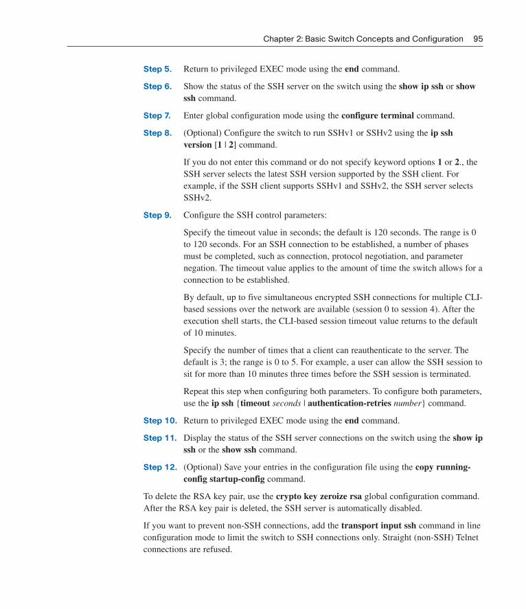
Step 5. Return to privileged EXEC mode using the end command.
Step 6. Show the status of the SSH server on the switch using the show ip ssh or showssh command.
Step 7. Enter global configuration mode using the configure terminal command.
Step 8. (Optional) Configure the switch to run SSHv1 or SSHv2 using the ip ssh version [1 | 2] command.
If you do not enter this command or do not specify keyword options 1 or 2., theSSH server selects the latest SSH version supported by the SSH client. Forexample, if the SSH client supports SSHv1 and SSHv2, the SSH server selectsSSHv2.
Step 9. Configure the SSH control parameters:
Specify the timeout value in seconds; the default is 120 seconds. The range is 0to 120 seconds. For an SSH connection to be established, a number of phasesmust be completed, such as connection, protocol negotiation, and parameternegation. The timeout value applies to the amount of time the switch allows for aconnection to be established.
By default, up to five simultaneous encrypted SSH connections for multiple CLI-based sessions over the network are available (session 0 to session 4). After theexecution shell starts, the CLI-based session timeout value returns to the defaultof 10 minutes.
Specify the number of times that a client can reauthenticate to the server. Thedefault is 3; the range is 0 to 5. For example, a user can allow the SSH session tosit for more than 10 minutes three times before the SSH session is terminated.
Repeat this step when configuring both parameters. To configure both parameters,use the ip ssh {timeout seconds | authentication-retries number} command.
Step 10. Return to privileged EXEC mode using the end command.
Step 11. Display the status of the SSH server connections on the switch using the show ipssh or the show ssh command.
Step 12. (Optional) Save your entries in the configuration file using the copy running-config startup-config command.
To delete the RSA key pair, use the crypto key zeroize rsa global configuration command.After the RSA key pair is deleted, the SSH server is automatically disabled.
If you want to prevent non-SSH connections, add the transport input ssh command in lineconfiguration mode to limit the switch to SSH connections only. Straight (non-SSH) Telnetconnections are refused.
Chapter 2: Basic Switch Concepts and Configuration 95
03_1587132079_ch02.qxd 3/27/08 2:33 PM Page 95

Example 2-10 demonstrates a set of commands to enable SSH on a Catalyst 2960 switch.The default version for SSH would be version 2, but we configure it anyway. This configu-ration prevents Telnet access on the vty lines. It is assumed that there are entries in the localusername database and that a vty password has been configured. Step 3 and 4 in the preced-ing list provide an absolute minimum set of commands to enable SSH.
Example 2-10 Enabling the SSH Server on the Catalyst 2960
96 LAN Switching and Wireless, CCNA Exploration Companion Guide
S1(config)# ip domain-name mydomain.com
S1(config)# crypto key generate rsa
S1(config)# ip ssh version 2
S1(config)# line vty 0 15
S1(config-line)# transport input ssh
For a detailed discussion on SSH, visit: www.cisco.com/en/US/tech/tk583/tk617/tsd_technology_support_protocol_home.html.
For an overview of RSA technology, visit en.wikipedia.org/wiki/Public-key_cryptography.
For a detailed discussion on RSA technology, visit:www.rsa.com/rsalabs/node.asp?id=2152.
Common Security Attacks
Unfortunately, basic switch security does not stop malicious attacks from occurring. In thissection, you learn about a few common security attacks and how dangerous they are. Thistopic provides introductory-level information about security attacks. The details of howsome of these common attacks work are beyond the scope of this book. If you would like todelve deeper into network security, refer to the Accessing the WAN, CCNA ExplorationCompanion Guide.
We proceed to explore some of the more common Layer 2 security attacks.
MAC Address FloodingThe MAC address table in a switch contains the MAC addresses available on a given physicalport of a switch and the associated VLAN parameters for each. When a Layer 2 switchreceives a frame, the switch looks in the MAC address table for the destination MAC address.All Catalyst switch models use a MAC address table for Layer 2 switching. As frames arriveon switch ports, the source MAC addresses are learned and recorded in the MAC addresstable. If an entry exists for the MAC address, the switch forwards the frame to the MACaddress port designated in the MAC address table. If the MAC address does not exist, theswitch forwards the frame out every other port on the switch. MAC address table overflowattacks are sometimes referred to as MAC flooding attacks. To understand the mechanism of aMAC address table overflow attack, we recall the basic operation of a switch.
03_1587132079_ch02.qxd 3/27/08 2:33 PM Page 96

In Figure 2-18, Host A sends traffic to Host B. The switch receives the frames and looks upthe destination MAC address in its MAC address table. If the switch cannot find the desti-nation MAC in the MAC address table, the switch then copies the frame and sends it outevery other switch port.
Figure 2-18 Switch Receives Unicast Frame
Chapter 2: Basic Switch Concepts and Configuration 97
The MAC addresstable is incomplete.
The MAC C seestraffic to MAC B.
B is unknown, so theswitch will flood theframe.
MAC
A
C
Port
1
3
A>B
A>B
A>B
MAC A
MAC B
MAC C
Port 2
Port 3Port 1
In Figure 2-19, Host B receives the frame and sends a reply to Host A. The switch thenlearns that the MAC address for Host B is located on port 2 and writes that information intothe MAC address table.
Figure 2-19 Host B Receives Unicast Frame
MAC address tablelearns that B is on Port 2.
C drops the packetaddressed to B.
MAC
A
B
C
Port
1
2
3
B>A
B>A
MAC A
MAC B
MAC C
Port 2
Port 3Port 1
03_1587132079_ch02.qxd 3/27/08 2:33 PM Page 97

You see that Host C also receives the frame from Host A to Host B, but because the destina-tion MAC address of that frame is Host B, Host C drops that frame.
In Figure 2-20, any frame sent now by Host A (or any other host) to Host B is forwarded toport 2 of the switch and not sent out every port.
Figure 2-20 Switch Forwards Frame Out Single Port
98 LAN Switching and Wireless, CCNA Exploration Companion Guide
MAC address tables are limitedin size.
MAC C does not seetraffic to MAC Banymore.
MAC address tablehas learned B is onPort 2.
MAC
A
B
C
Port
1
2
3
A>B
A>B
MAC A
MAC B
MAC C
Port 2
Port 3Port 1
The key to understanding how MAC address table overflow attacks work is to know thatMAC address tables are limited in size. MAC flooding makes use of this limitation to bom-bard the switch with fake source MAC addresses until the switch MAC address table is full.The switch then enters into what is known as a fail-open mode, starts acting as a hub, andbroadcasts packets to all the machines on the network. As a result, the attacker can see allof the frames sent from a victim host to another host.
MAC flooding can be performed using a network attack tool. The network intruder uses theattack tool to flood the switch with a large number of invalid source MAC addresses untilthe MAC address table fills up. When the MAC address table is full, the switch floods allports with incoming traffic because it cannot find the port number for a particular MACaddress in the MAC address table. The switch, in essence, acts like a hub.
Some network attack tools can generate 155,000 MAC entries on a switch per minute.Depending on the switch, the maximum MAC address table size varies. In Figure 2-21, theattack tool is running on the host with MAC address C in the bottom right of the screen.This tool floods a switch with packets containing randomly generated source and destina-tion MAC and IP addresses. Over a short period of time, the MAC address table in theswitch fills up until it cannot accept new entries. When the MAC address table fills up withinvalid source MAC addresses, the switch begins to forward all frames that it receives toevery port.
03_1587132079_ch02.qxd 3/27/08 2:33 PM Page 98

Figure 2-21 Host C Sends Frames with Bogus Sources
Chapter 2: Basic Switch Concepts and Configuration 99
Bogus addressesare added to theMAC addresstable.
Attacker startssending unknownbogus MACaddresses
X and Y are on Port 3and the MAC addresstable is updated.
Intruder runs an attack tool on MAC C.
MAC
X
Y
Z
Port
3
3
3
Y>?
MAC A
MAC B
MAC C
Port 2
Port 3Port 1
X>
?
As long as the network attack tool is left running, the MAC address table on the switchremains full. When this happens, the switch begins to send all received frames out everyport so that frames sent from Host A to Host B are also sent out of port 3 on the switch, asshown in Figure 2-22.
Figure 2-22 Host C Sees All Frames Sent from Host A to Host B
The MAC addresstable is full.
Mac B is unknown,so the switch floodsthe frame looking forMAC B.
MAC
X
Y
Z
Port
3
3
3
A>B
A>B
A>B
MAC A
MAC B
MAC C
Port 2
Port 3Port 1
03_1587132079_ch02.qxd 3/27/08 2:33 PM Page 99

Spoofing AttacksOne way an attacker can gain access to network traffic is to spoof responses that would besent by a valid DHCP server. The DHCP spoofing device replies to client DHCP requests.The legitimate server may also reply, but if the spoofing device is on the same segment asthe client, its reply to the client may arrive first. The intruder DHCP reply offers an IPaddress and supporting information that designates the intruder as the default gateway orDomain Name System (DNS) server. In the case of a gateway, the clients then forwardpackets to the attacking device, which in turn, sends them to the desired destination. This isreferred to as a man-in-the-middle attack, and it may go entirely undetected as the intruderintercepts the data flow through the network.
You should be aware of another type of DHCP attack called a DHCP starvation attack. Theattacker PC continually requests IP addresses from a real DHCP server by changing thesource MAC addresses of the requests. If successful, this kind of DHCP attack causes allthe leases on the real DHCP server to be allocated, thus preventing the real users (DHCPclients) from obtaining an IP address.
To prevent DHCP attacks, use the DHCP snooping and port security features on the CiscoCatalyst switches.
DHCP snooping is a Cisco Catalyst feature that determines which switch ports can respondto DHCP requests. Ports are identified as trusted and untrusted, as illustrated in Figure 2-23.Trusted ports can source all DHCP messages; untrusted ports can source requests only.Trusted ports host a DHCP server or can be an uplink toward the DHCP server. If a roguedevice on an untrusted port attempts to send a DHCP response packet into the network, theport is shut down. This feature can be coupled with DHCP options in which switch informa-tion, such as the port ID of the DHCP request, can be inserted into the DHCP request packet.
Figure 2-23 DHCP Snooping to Prevent DHCP Attacks
100 LAN Switching and Wireless, CCNA Exploration Companion Guide
Rogue DHCPAttacker
Legitimate DHCPServer
Trusted Port
Untrusted Port
Client
03_1587132079_ch02.qxd 3/27/08 2:33 PM Page 100

Untrusted ports are those not explicitly configured as trusted. A DHCP binding table is builtfor untrusted ports. Each entry contains a client MAC address, IP address, lease time, bind-ing type, VLAN number, and port ID recorded as clients make DHCP requests. The table isthen used to filter subsequent DHCP traffic. From a DHCP snooping perspective, untrustedaccess ports should not send any DHCP server responses.
These steps illustrate how to configure DHCP snooping on a Cisco IOS switch:
Step 1. Enable DHCP snooping using the ip dhcp snooping global configuration com-mand.
Step 2. Enable DHCP snooping for specific VLANs using the ip dhcp snooping vlannumber [number] command.
Step 3. Define ports as trusted or untrusted at the interface level by defining the trustedports using the ip dhcp snooping trust command.
Step 4. (Optional) Limit the rate at which an attacker can continually send bogus DHCPrequests through untrusted ports to the DHCP server using the ip dhcp snoopinglimit rate rate command.
CDP AttacksThe Cisco Discovery Protocol (CDP) is a proprietary protocol that all Cisco devices can beconfigured to use. CDP discovers other Cisco devices that are directly connected, whichallows the devices to autoconfigure their connection in some cases, simplifying configura-tion and connectivity. CDP messages are not encrypted.
By default, most Cisco devices have CDP enabled. CDP information is sent in periodicbroadcasts that are updated locally in each device’s CDP database. Because CDP is a Layer2 protocol, it is not propagated by routers.
CDP contains information about the device, such as the IP address, software version, plat-form, capabilities, and the native VLAN. When this information is available to an attacker,they can use it to find exploits to attack your network, typically in the form of a Denial ofService (DoS) attack.
Figure 2-24 is a portion of a packet capture showing the inside of a CDP packet. The CiscoIOS Software version discovered via CDP, in particular, would allow the attacker toresearch and determine whether there were any security vulnerabilities specific to that par-ticular version of code. Also, because CDP is unauthenticated, an attacker could craft bogusCDP packets and have them received by the attacker’s directly connected Cisco device.
To address this vulnerability, it is recommended that you disable the use of CDP on devicesthat do not need to use it.
Chapter 2: Basic Switch Concepts and Configuration 101
How To
03_1587132079_ch02.qxd 3/27/08 2:33 PM Page 101

Figure 2-24 CDP Packet Capture
102 LAN Switching and Wireless, CCNA Exploration Companion Guide
Telnet AttacksThe Telnet protocol can be used by an attacker to gain remote access to a Cisco switch. Youhave configured a login password for vty lines and set the lines to require password authenti-cation to gain access. This ensures an essential and basic level of security to help protect theswitch from unauthorized access. However, it is not a secure method of securing access to thevty lines. There are tools available that allow an attacker to launch a brute-force password-cracking attack against the vty lines on the switch.
The first phase of a brute-force password attack starts with the attacker using a list of com-mon passwords and a program designed to try to establish a Telnet session using each wordon the dictionary list. Because your passwords do not resemble any dictionary words, youare safe for now. In the second phase of a brute-force attack, the attacker uses a programthat creates sequential character combinations in an attempt to “guess” the password. Givenenough time, a brute force password attack can crack almost any passwords used.
The simplest thing that you can do to limit the vulnerability to brute-force password attacksis to change your passwords frequently and use strong passwords, randomly mixing upperand lowercase letters with other alphanumeric characters. More advanced configurationsallow you to limit who can communicate with the vty lines by using access lists, but that isbeyond the scope of this book.
Another type of Telnet attack is the DoS attack. In a DoS attack, the attacker exploits a flawin the Telnet server software running on the switch that renders the Telnet service unavail-able. This sort of attack is mostly a nuisance because it prevents an administrator from per-forming switch management functions.
Vulnerabilities in the Telnet service that permit DoS attacks to occur are usually addressedin security patches that are included in newer Cisco IOS revisions. If you are experiencing a
03_1587132079_ch02.qxd 3/27/08 2:33 PM Page 102

DoS attack against the Telnet service, or any other service on a Cisco device, check to see ifa newer Cisco IOS revision is available.
Last, if an attacker uses a MAC flooding attack, for example, by using any packet capturesoftware, the attacker may then capture the Telnet password as you type it.
Security Tools
After you have configured switch security, you need to verify that you have not left anyweakness for an attacker to exploit. Network security is a complex and evolving set of tech-nologies. In this section, you are introduced to how network security tools are used to pro-tect a network from malicious attacks.
Network security tools help you to test your network for various weaknesses. They are toolsthat allow you to play the role of both a hacker and a network security analyst. Using thesetools, you can launch an attack and audit the results to determine how to adjust your securi-ty policies to prevent specific attacks.
The features used within network security tools are many and varied. For example, networksecurity tools formerly focused only on the services of listening on the network and exam-ined these services for flaws. Today, viruses and worms are able to propagate because offlaws in mail clients and web browsers. Modern network security tools not only detect theremote flaws of the hosts on the network, but also determine whether application-levelflaws exist, such as missing patches on client computers. Network security extends beyondnetwork devices, all the way to the desktop of users. Security auditing and penetration test-ing are two basic functions that network security tools perform.
Network security tools allow you to perform a security audit of your network. A securityaudit reveals what sort of information an attacker can gather simply by monitoring networktraffic. Network security-auditing tools allow you to flood the MAC table with bogus MACaddresses. Then you can audit the switch ports as the switch starts flooding traffic out allports as the legitimate MAC address mappings are aged out and replaced with more bogusMAC address mappings. In this way, you can determine which ports are compromised andhave not been correctly configured to prevent this type of attack.
Timing is an important factor in performing a successful audit. Different switches supportvarying numbers of MAC addresses in their MAC address tables. It can be tricky to deter-mine the ideal amount of spoofed MAC addresses to throw out on the network. You alsohave to contend with the age-out period of the MAC table. If the spoofed MAC addressesstart to age out while you are performing your network audit, valid MAC addresses start topopulate the MAC table, limiting the data that you can monitor with a network-auditingtool.
Network security tools can also be used for penetration testing against your network. Thisallows you to identify weaknesses within the configuration of your networking devices.There are numerous attacks that you can perform, and most tool suites come with extensive
Chapter 2: Basic Switch Concepts and Configuration 103
03_1587132079_ch02.qxd 3/27/08 2:33 PM Page 103
documentation detailing the syntax needed to execute the desired attack. Because thesetypes of tests can have adverse effects on the network, they are carried out under very con-trolled conditions, following documented procedures detailed in a comprehensive networksecurity policy. Of course, if you have a lab-based network, you can arrange to try yourown network penetration tests.
In the next section, you learn how to implement port security on your Cisco switches sothat you can ensure these network security tests do not reveal any flaws in your securityconfiguration.
A secure network really is a process, not a product. You cannot just enable a switch with asecure configuration and declare the job to be done. To say you have a secure network, youneed to have a comprehensive network security plan defining how to regularly verify thatyour network can withstand the latest malicious network attacks. The changing landscape ofsecurity risks means that you need auditing and penetration tools that can be updated tolook for the latest security risks. Common features of a modern network security toolinclude the following:
■ Service identification: Tools that are used to target hosts using the Internet AssignedNumbers Authority (IANA) port numbers. These tools should also be able to discoveran FTP server running on a nonstandard port or a web server running on port 8080.The tool should also be able to test all the services running on a host.
■ Support of SSL services: Testing services that use SSL level security, includingHTTPS, SMTPS, IMAPS, and security certificates.
■ Nondestructive and destructive testing: Performing nondestructive security audits ona routine basis that do not compromise or only moderately compromise network per-formance. The tools should also let you perform destructive audits that significantlydegrade network performance. Destructive auditing allows you to see how well yournetwork withstands attacks from intruders.
■ Database of vulnerabilities: Vulnerabilities change with time.
Network security tools need to be designed so that they can plug into a module of code andthen run a test for a specific vulnerability. In this way, a large database of vulnerabilitiescan be maintained and uploaded to the tool to ensure that the most recent vulnerabilities arebeing tested.
You can use network security tools to
■ Capture chat messages
■ Capture files from NFS traffic
■ Capture HTTP requests in Common Log Format
■ Capture mail messages in Berkeley mbox format
■ Capture passwords
104 LAN Switching and Wireless, CCNA Exploration Companion Guide
03_1587132079_ch02.qxd 3/27/08 2:33 PM Page 104

■ Display captured URLs in browser in real-time
■ Flood a switched LAN with random MAC addresses
■ Forge replies to DNS address or pointer queries
■ Intercept packets on a switched LAN
Configuring Port Security
A switch that does not provide port security allows an attacker to attach a system to anunused, enabled port and to perform information gathering or to launch attacks. A switchcan be configured to act like a hub, which means that every system connected to the switchcan potentially view all network traffic passing through the switch to all systems connectedto the switch. Thus, an attacker could collect traffic that contains usernames, passwords, orconfiguration information about the systems on the network.
All switch ports or interfaces should be secured before the switch is deployed. Port securitylimits the number of valid MAC addresses allowed on a port. When you assign secure MACaddresses to a secure port, the port does not forward packets with source addresses outsidethe group of defined addresses.
If you limit the number of secure MAC addresses to one and assign a single secure MACaddress to that port, the workstation attached to that port is assured the full bandwidth ofthe port, and only that workstation with that particular secure MAC address can successful-ly communicate through that switch port.
If a port is configured as a secure port and the maximum number of secure MAC addressesis reached, a security violation occurs when the MAC address of a workstation attemptingto access the port is different from any of the identified secure MAC addresses.Summarizing, you should implement security on all switch ports to
■ Specify a group of valid MAC addresses allowed on a port.
■ Allow only one MAC address to access the port at a time.
■ Specify that the port automatically shuts down if unauthorized MAC addresses aredetected.
There are a number of ways to configure port security. The following describes the waysyou can configure port security on a Cisco switch:
■ Static secure MAC addresses: MAC addresses are manually configured by using theswitchport port-security mac-address mac-address interface configuration command.MAC addresses configured in this way are stored in the address table and are added tothe running configuration on the switch.
■ Dynamic secure MAC addresses: MAC addresses are dynamically learned and storedonly in the address table. MAC addresses configured in this way are removed when theswitch restarts.
Chapter 2: Basic Switch Concepts and Configuration 105
03_1587132079_ch02.qxd 3/27/08 2:33 PM Page 105

■ Sticky secure MAC addresses: You can configure a port to dynamically learn MACaddresses and then save these MAC addresses to the running configuration.
Sticky secure MAC addresses have the following characteristics:
■ When you enable sticky learning on an interface by using the switchport port-securitymac-address sticky interface configuration command, the interface converts all thedynamic secure MAC addresses, including those that were dynamically learned beforesticky learning was enabled, to sticky secure MAC addresses and adds all sticky secureMAC addresses to the running configuration.
■ If you disable sticky learning by using the no switchport port-security mac-addresssticky interface configuration command, the sticky secure MAC addresses remain partof the running configuration but are removed from the address table. The addresses thatwere removed can be dynamically reconfigured and added to the address table asdynamic addresses.
■ When you configure sticky secure MAC addresses by using the switchport port-security mac-address sticky mac-address interface configuration command, theseaddresses are added to the address table and the running configuration. If port securityis disabled, the sticky secure MAC addresses remain in the running configuration.
■ If you save the sticky secure MAC addresses in the configuration file, when the switchrestarts or the interface shuts down, the interface does not need to relearn theseaddresses. If you do not save the sticky secure addresses, they are lost. If sticky learn-ing is disabled, the sticky secure MAC addresses are converted to dynamic secureaddresses and are removed from the running configuration.
■ If you disable sticky learning and enter the switchport port-security mac-addresssticky mac-address interface configuration command, an error message appears, andthe sticky secure MAC address is not added to the running configuration.
It is a security violation when either of these situations occurs:
■ The maximum number of secure MAC addresses have been added to the address table,and a station whose MAC address is not in the address table attempts to access theinterface.
■ An address learned or configured on one secure interface is seen on another secureinterface in the same VLAN.
You can configure the interface for one of three violation modes, based on the action to betaken if a violation occurs.
■ protect: When the number of secure MAC addresses reaches the limit allowed on theport, packets with unknown source addresses are dropped until you remove a sufficientnumber of secure MAC addresses or increase the number of maximum allowableaddresses. You are not notified that a security violation has occurred.
106 LAN Switching and Wireless, CCNA Exploration Companion Guide
03_1587132079_ch02.qxd 3/27/08 2:33 PM Page 106

■ restrict: When the number of secure MAC addresses reaches the limit allowed on theport, packets with unknown source addresses are dropped until you remove a sufficientnumber of secure MAC addresses or increase the number of maximum allowableaddresses. In this mode, you are notified that a security violation has occurred.Specifically, an SNMP trap is sent, a syslog message is logged, and the violation counter increments.
■ shutdown: In this mode, a port security violation causes the interface to immediatelybecome error-disabled and turns off the port LED. It also sends an SNMP trap, logs asyslog message, and increments the violation counter. When a secure port is in theerror-disabled state, you can bring it out of this state by entering the shutdown fol-lowed by the no shutdown interface configuration commands. This is the defaultmode.
The effect of each mode is summarized in Table 2-15.
Table 2-15 Port Security Violation Modes
Sends Sends Displays Increases Shuts
Violation Forwards SNMP Syslog Error Violation Down
Mode Traffic Trap Message Message Counter Port
Protect No No No No No No
Restrict No Yes Yes No Yes No
Shutdown No Yes Yes No Yes Yes
The ports on a Catalyst switch are preconfigured with defaults. Table 2-16 summarizes thedefault port security configuration.
Table 2-16 Port Security Default Settings
Feature Default Setting
Port security Disabled on a port.
Maximum number of secure MAC addresses 1
Violation mode Shutdown. The port shuts down when themaximum number of secure MACaddresses is exceeded, and an SNMP trapnotification is sent.
Sticky address learning Disabled.
Table 2-17 shows the Cisco IOS CLI commands needed to configure port security on theinterface F0/18 of switch S1. Notice that the example does not specify a violation mode. Inthis example, the violation mode defaults to shutdown.
Chapter 2: Basic Switch Concepts and Configuration 107
03_1587132079_ch02.qxd 3/27/08 2:33 PM Page 107

Table 2-17 Port Security Command Syntax
Description Command
Enters global configuration mode. S1# configure terminal
Specifies the type and number of the S1(config)# interface fastEthernet 0/18
physical interface to configure—for example,fastEthernet 0/18—and enters interface configuration mode.
Sets the interface mode as access. An S1(config-if)# switchport mode access
interface in the dynamic desirable default mode cannot be configured as a secure port.
Enables port security on the interface. S1(config-if)# switchport port-security
Returns to privileged EXEC mode. S1# end
Table 2-18 shows how to enable sticky port security on interface F0/18 of switch S1. Recallthat you can configure the maximum number of secure MAC addresses. In this example,you see the Cisco IOS command syntax used to set the maximum number of MAC address-es to 50. The violation mode is again set to shutdown by default.
Table 2-18 Port Security Command Syntax with Sticky Addresses
Description Command
Enters global configuration mode. S1# configure terminal
Specifies the type and number of S1(config)# interface fastEthernet 0/18
the physical interface to configure.
Sets the interface mode as access. S1(config-if)# switchport mode access
Enables port security on the interface. S1(config-if)# switchport port-security
Sets the maximum number of secure S1(config-if)# switchport
addresses to 50. port-security maximum 50
Enables sticky learning. S1(config-if)# switchport port-security
mac-address sticky
Returns to privileged EXEC mode. S1# end
Other port security settings exist that you may find useful. For a complete listing of portsecurity configuration options, visit: cisco.com/en/US/docs/switches/lan/catalyst2950/software/release/12.1_19_ea1/configuration/guide/swtrafc.html#wp1038501.
108 LAN Switching and Wireless, CCNA Exploration Companion Guide
03_1587132079_ch02.qxd 3/27/08 2:33 PM Page 108

After you have configured port security for your switch, you should verify that it has beenconfigured correctly. You need to check each interface to verify that you have set the portsecurity correctly. You also have to check to make sure that you have configured any staticMAC addresses correctly.
To display port security settings for the switch or for the specified interface, use the showport-security [interface interface-id] command, as illustrated in Example 2-11.
Example 2-11 Verifying Port Security
Chapter 2: Basic Switch Concepts and Configuration 109
S1# show port-security interface fastEthernet 0/18
Port Security :Enabled
Port Status :Secure-down
Violation Mode :Shutdown
Aging Time :0 mins
Aging Type :Absolute
SecureStatic Address Aging :Disabled
Maximum MAC Addresses :1
Total MAC Addresses :1
Configured MAC Addresses :0
Sticky MAC Addresses :0
Last Source Address:Vlan :0000.0000.0000:0
Security Violation Count :0
The output displays the following:
■ Maximum allowed number of secure MAC addresses for each interface
■ Number of secure MAC addresses on the interface
■ Number of security violations that have occurred
■ Violation mode
To display all secure MAC addresses configured on all switch interfaces or on a specifiedinterface with aging information for each, use the show port-security [interfaceinterface-id] address command, as illustrated in Example 2-12.
Example 2-12 Verifying Secure MAC Addresses
S1# show port-security address
Secure Mac Address Table
------------------------------------------------------------------------
Vlan Mac Address Type Ports Remaining Age (mins)
99 0050.BAA6.06CE SecureConfigured Fa0/18 -
------------------------------------------------------------------------
Total Addresses in System (excluding one mac per port) : 0
Max Addresses limit in System (excluding one mac per port) : 8320
03_1587132079_ch02.qxd 3/27/08 2:33 PM Page 109

Securing Unused Ports
Securing unused switch ports is a security best practice for switch configuration. Here youlearn a simple Cisco IOS command to secure unused switch ports. A method many adminis-trators use to help secure their networks from unauthorized access is to disable all unusedports on a network switch. For example, imagine that a Cisco 2960 switch has 24 ports. Ifthree Fast Ethernet connections are in use, good security practice demands that you disablethe 21 unused ports. Example 2-13 shows partial output for this configuration.
Example 2-13 Shutdown Unused Ports
110 LAN Switching and Wireless, CCNA Exploration Companion Guide
interface FastEthernet0/4
shutdown
!
interface FastEthernet0/5
shutdown
!
interface FastEthernet0/6
shutdown
!
<output omitted>
!
interface FastEthernet0/18
switchport mode access
switchport port-security
It is simple to disable multiple ports on a switch. Navigate to each unused port and issuethis Cisco IOS shutdown command. A better way to shut down multiple ports is to use theinterface range command. If a port needs to be activated, you can manually enter the noshutdown command on that interface.
The process of enabling and disabling ports can become a tedious task, but the value interms of enhancing security on your network is well worth the effort. In the next chapteryou will also see that it is a security best practice to configure all unused switch ports to bemembers of a “black hole” VLAN, which is a dummy VLAN that is not used anywhere inthe switched LAN.
Configure Switch Security (2.4.7)
Use the Packet Tracer Activity to configure basic switch commands and then configure andtest port security. Use File e3-2472.pka on the CD-ROM that accompanies this book to per-form this activity using Packet Tracer.
Packet Tracer Activity
03_1587132079_ch02.qxd 3/27/08 2:33 PM Page 110

Chapter 2: Basic Switch Concepts and Configuration 111
Summary
In this chapter, we discussed IEEE 802.3 Ethernet communication using unicast, broadcast,and multicast traffic. Early implementations of Ethernet networks needed to use CSMA/CDto help prevent and detect collisions between frames on the network. Duplex settings andLAN segmentation improve performance and reduce the need for CSMA/CD.
LAN design is a process; the intended result of LAN design is a determination of how aLAN is to be implemented. LAN design considerations include collision domains, broad-cast domains, network latency, and LAN segmentation.
We discussed how switch forwarding methods influence LAN performance and latency.Memory buffering plays a role in switch forwarding, symmetric and asymmetric switching,and multilayer switching.
An introduction to navigating the Cisco IOS CLI on a Cisco Catalyst 2960 switch was pre-sented. Built-in help functions are used to identify commands and command options. TheCisco IOS CLI maintains a command history that allows you to more quickly configurerepetitive switch functions.
We discussed the initial switch configuration and how to verify the switch configuration.Backing up a switch configuration and restoring a switch configuration are key skills foranyone administering a switch.
We learned how to secure access to the switch: implementing passwords to protect consoleand virtual terminal lines, implementing passwords to limit access to privileged EXEC mode,configuring password encryption, and enabling SSH. There are a number of security riskscommon to Cisco Catalyst switches, many of which are mitigated by using port security.
Labs
The labs available in the companion LAN Switching and Wireless, CCNA Exploration Labsand Study Guide (ISBN 1-58713-202-8) provide hands-on practice with the following top-ics introduced in this chapter:
Lab 2-1: Basic Switch Configuration (2.5.1)
In this lab, you examine and configure a standalone LAN switch. Although a switch per-forms basic functions in its default out-of-the-box condition, a network administrator shouldmodify a number of parameters to ensure a secure and optimized LAN. This activity intro-duces you to the basics of switch configuration.
03_1587132079_ch02.qxd 3/27/08 2:33 PM Page 111
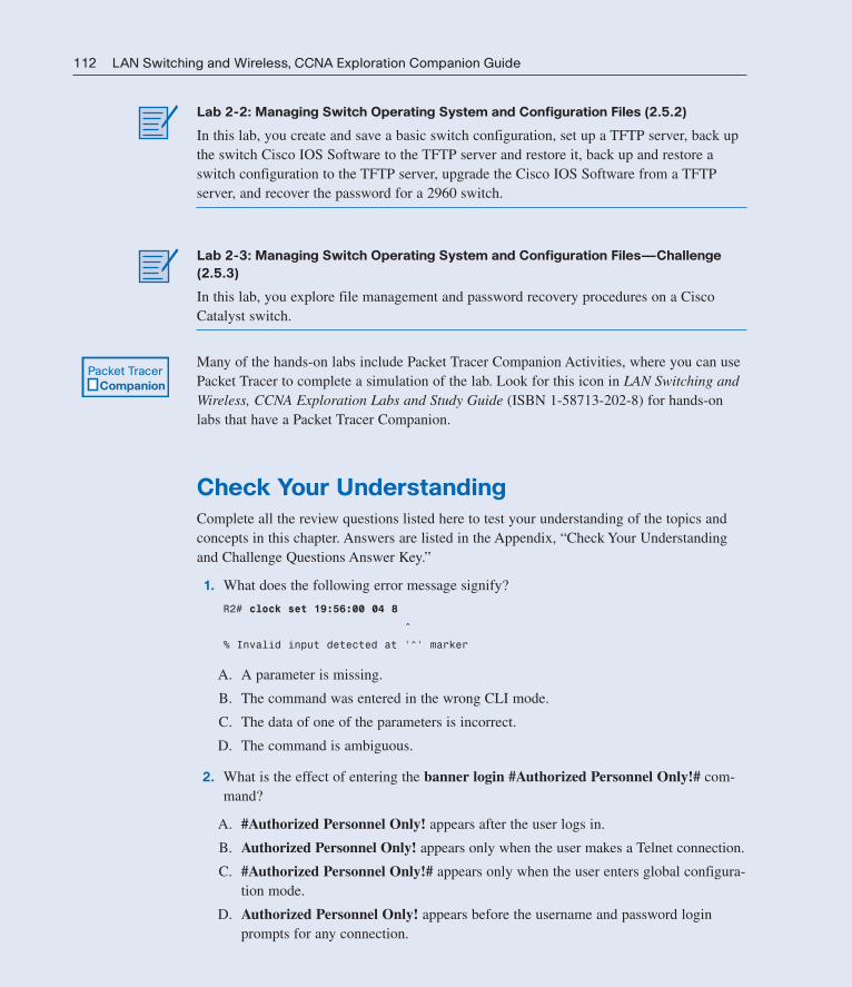
112 LAN Switching and Wireless, CCNA Exploration Companion Guide
Lab 2-2: Managing Switch Operating System and Configuration Files (2.5.2)
In this lab, you create and save a basic switch configuration, set up a TFTP server, back upthe switch Cisco IOS Software to the TFTP server and restore it, back up and restore aswitch configuration to the TFTP server, upgrade the Cisco IOS Software from a TFTPserver, and recover the password for a 2960 switch.
Lab 2-3: Managing Switch Operating System and Configuration Files—Challenge
(2.5.3)
In this lab, you explore file management and password recovery procedures on a CiscoCatalyst switch.
Many of the hands-on labs include Packet Tracer Companion Activities, where you can usePacket Tracer to complete a simulation of the lab. Look for this icon in LAN Switching andWireless, CCNA Exploration Labs and Study Guide (ISBN 1-58713-202-8) for hands-onlabs that have a Packet Tracer Companion.
Check Your Understanding
Complete all the review questions listed here to test your understanding of the topics andconcepts in this chapter. Answers are listed in the Appendix, “Check Your Understandingand Challenge Questions Answer Key.”
1. What does the following error message signify?
R2# clock set 19:56:00 04 8
^
% Invalid input detected at ‘^’ marker
A. A parameter is missing.
B. The command was entered in the wrong CLI mode.
C. The data of one of the parameters is incorrect.
D. The command is ambiguous.
2. What is the effect of entering the banner login #Authorized Personnel Only!# com-mand?
A. #Authorized Personnel Only! appears after the user logs in.
B. Authorized Personnel Only! appears only when the user makes a Telnet connection.
C. #Authorized Personnel Only!# appears only when the user enters global configura-tion mode.
D. Authorized Personnel Only! appears before the username and password loginprompts for any connection.
Packet Tracer Companion
03_1587132079_ch02.qxd 3/27/08 2:33 PM Page 112

Chapter 2: Basic Switch Concepts and Configuration 113
3. Which three options correctly associate the command with the paired behavior?(Choose three.)
A. switchport port-security violation protect: Frames with unknown source addressesare dropped and a notification is sent.
B. switchport port-security violation restrict: Frames with unknown source address-es are dropped and no notification is sent.
C. switchport port-security violation shutdown: Frames with unknown sourceaddresses result in the port becoming error-disabled and a notification is sent.
D. switchport port-security mac-address sticky: Allows dynamically learned MACaddresses to be stored in the running-configuration.
E. switchport port-security maximum: Defines the number of MAC addresses asso-ciated with a port.
4. Refer to Figure 2-25. An Ethernet switch has built the MAC address table shown. Whataction will the switch take when it receives the frame shown at the bottom of the exhibit?
Figure 2-25 MAC Address Table
Station
00-00-3D-1F-11-01
00-00-3D-1F-11-02
00-00-3D-1F-11-03
Interface1 Interface2 Interface3 Interface4
X
X
X
Destination
00-00-3D-1F-11-03 00-00-3D-1F-11-01
Source Data CRC
A. Forward the frame out all interfaces.
B. Forward the frame out all interfaces except Interface3.
C. Discard the frame.
D. Forward the frame out Interface1.
E. Forward the frame out Interface2.
F. Forward the frame out Interface3.
5. What can be determined from the following command output?
Switch# show version
<output omitted>
Compiled Wed 18-May-07 22:31
<output omitted>
Running Standard Image
03_1587132079_ch02.qxd 3/27/08 2:33 PM Page 113

114 LAN Switching and Wireless, CCNA Exploration Companion Guide
24 FastEthernet/IEEE 802.3 interface(s)
2 Gigabit Ethernet/IEEE 802.3 interface(s)
32K bytes of flash-simulated non-volatile configuration memory.
<output omitted>
A. The system has 32 KB of NVRAM.
B. The switch has 24 physical ports
C. The system was last restarted on May 18, 2005.
D. The Cisco IOS is a nonstandard image.
6. What advantage does SSH offer over Telnet when remotely connecting to a device?
A. Encryption
B. More connection lines
C. Connection-oriented services
D. Username and password authentication
7. Refer to Figure 2-26. How many collision and broadcast domains are displayed in thenetwork?
Figure 2-26 Collision and Broadcast Domains
PC_C PC_D
R1
S2S1
PC_A PC_B
HB1
PC_G PC_H
S4S3
PC_E PC_F
R2
A. 8 collision, 2 broadcast
B. 8 collision, 3 broadcast
C. 11 collision, 4 broadcast
D. 13 collision, 2 broadcast
03_1587132079_ch02.qxd 3/27/08 2:33 PM Page 114

Chapter 2: Basic Switch Concepts and Configuration 115
8. Which option correctly associates the Layer 2 security attack with the description?
A. MAC address flooding: Broadcast requests for IP addresses with spoofed MACaddresses.
B. DHCP starvation: Using proprietary Cisco protocols to gain information about aswitch.
C. CDP attack: The attacker fills the switch MAC address table with invalid MACaddresses.
D. Telnet attack: Using brute force password attacks to gain access to a switch.
9. Which three statements are true about the CSMA/CD access method? (Choose three.)
A. In an Ethernet LAN, each station continuously listens for traffic on the medium todetermine when gaps between frame transmissions occur and then sends the frame.
B. In an Ethernet LAN, stations may begin transmitting anytime they detect that thenetwork is quiet (there is no traffic).
C. In the CSMA/CD process, priorities are assigned to particular stations, and the sta-tion with the highest priority transmits frames on the medium.
D. If a collision occurs in an Ethernet LAN, transmitting stations stop transmitting andwait a random length of time before attempting to retransmit the frame.
E. If a collision occurs in an Ethernet LAN, only the station with the highest prioritycontinues to transmit, and the rest of the stations wait a random length of timebefore attempting to retransmit the frame.
F. In an Ethernet LAN, all stations execute a backoff algorithm based on their assignedpriorities before they transmit frames on the medium.
10. How does the Ethernet switch process the incoming traffic using port-based memorybuffering?
A. The frames are stored in queues that are linked to specific incoming ports.
B. The frames are stored in queues that are linked to specific outgoing ports.
C. The frames are transmitted to the outgoing port immediately.
D. The frames are stored in queues that are linked to the common memory area.
11. What are two key features of an Ethernet switch with Layer 2 capabilities? (Choosetwo.)
A. Full-duplex operation
B. Broadcast and multicast traffic management
C. Security through access lists
D. Layer 3 routing functions
E. Filtering based on MAC address
F. Network address translation (NAT)
03_1587132079_ch02.qxd 3/27/08 2:33 PM Page 115

116 LAN Switching and Wireless, CCNA Exploration Companion Guide
12. The network administrator wants to configure an IP address on a Cisco switch. Howdoes the network administrator assign the IP address?
A. In privileged EXEC mode
B. On the switch interface FastEthernet0/0
C. On the management VLAN
D. On the physical interface connected to the router or next-hop device
13. Why should a default gateway be assigned to a switch?
A. So that there can be remote connectivity to the switch via such programs as Telnetand ping
B. So that frames can be sent through the switch to the router
C. So that frames generated from workstations and destined for remote networks canpass to a higher level
D. So that other networks can be accessed from the command prompt of the switch
14. Which two tasks does autonegotiation in an Ethernet network accomplish? (Choose two.)
A. Sets the link speed
B. Sets the IP address
C. Sets the link duplex mode
D. Sets MAC address assignments on switch port
E. Sets the ring speed
15. What is the effect of entering the SW1(config-if)# duplex full command on a FastEthernet switch port?
A. The connected device communicates in two directions, but only one direction at atime.
B. The switch port returns to its default configuration.
C. If the connected device is also set for full duplex, it participates in collision-freecommunication.
D. The efficiency of this configuration is typically rated at 50 to 60 percent.
E. The connected device should be configured as half duplex.
16. Which term describes the time delay between a frame being sent from a source deviceand received on a destination device?
A. Bandwidth
B. Latency
C. Attenuation
D. Time-to-live
E. Frame check sequence
03_1587132079_ch02.qxd 3/27/08 2:33 PM Page 116

Chapter 2: Basic Switch Concepts and Configuration 117
17. Which option correctly associates the command with the description?
A. copy startup-config running-config: Copy the current running configuration to aTFTP server.
B. copy running-config tftp: Save the current running configuration as the startupconfiguration.
C. copy tftp startup-config: Restore a configuration from a TFTP server to the run-ning configuration.
D. copy tftp running-config: Restore the startup configuration to the running system.
E. copy startup-config tftp: Restore the configuration from a TFTP server to the start-up configuration.
F. copy running-config startup config: Save the current running configuration to thestartup configuration
18. Which three options correctly associate the command with the description? (Choosethree.)
A. enable: Enter the global configuration mode.
B. configure terminal: Enter configuration mode for the console line.
C. line vty 0 15: Set a password.
D. line console 0: Enter configuration mode for the console line.
E. password cisco: Set a password.
F. username admin password cisco: Enable AAA.
G. login: Permit login.
Challenge Questions and Activities
Complete all the review questions listed here to test your understanding of the topics andconcepts in this chapter. Answers are listed in the Appendix, “Check Your Understandingand Challenge Questions Answer Key.”
1. Refer to Figure 2-27. There are six steps in the process of a switch learning a MACaddress for the purposes of forwarding Ethernet frames. Put the following six steps inorder by placing the appropriate number in the blank.
03_1587132079_ch02.qxd 3/27/08 2:33 PM Page 117

118 LAN Switching and Wireless, CCNA Exploration Companion Guide
Figure 2-27 Learning MAC Addresses
S1PC1
1 3
2
PC2
_______The intended destination device replies to the broadcast with a unicast frameaddressed to PC 1.
_______The switch enters the source MAC address and the switch port that received theframe into the address table.
_______The switch enters the source MAC address of PC 2 and the port number of theswitch port that received the frame into the address table. The destination addressof the frame and its associated port is found in the MAC address table.
_______The switch can now forward frames between source and destination devices with-out flooding, because it has entries in the address table that identify the associatedports.
_______Because the destination address is a broadcast, the switch floods the frame to allports, except the port on which it received the frame.
_______The switch receives an ARP broadcast frame from PC 1 on Port 1.
2. List the two principal switch forwarding methods and the two primary methods ofmemory buffering in switches.
________________________________________________________________________
________________________________________________________________________
3. From the following output, what is the likely reason for interface VLAN 99 displaying“up/down” as its status?
S1# show running-config
<output omitted>
!
interface FastEthernet0/18
switchport access vlan 99
switchport mode access
<output omitted>
!
interface Vlan99
ip address 172.17.99.11 255.255.255.0
no ip route-cache
03_1587132079_ch02.qxd 3/27/08 2:33 PM Page 118

Chapter 2: Basic Switch Concepts and Configuration 119
!
<output omitted>
S1# show ip interface brief
Interface IP-Address OK? Method Status Protocol
<output omitted>
Vlan99 172.17.99.11 YES NVRAM up up
<output omitted>
FastEthernet0/18 unassigned YES unset down down
FastEthernet0/19 unassigned YES unset down down
<output omitted>
GigabitEthernet0/2 unassigned YES unset down down
________________________________________________________________________
________________________________________________________________________
4. From the following configuration, which two commands are unnecessary for a basicSSH configuration providing remote access for SSH clients? (Choose two.)
Switch(config)# ip domain-name mydomain.com
Switch(config)# crypto key generate rsa
Switch(config)# ip ssh version 2
Switch(config)# line vty 0 15
Switch(config-if)# transport input ssh
________________________________________________________________________
________________________________________________________________________
5. List and describe the three port security violation modes.
________________________________________________________________________
________________________________________________________________________
________________________________________________________________________
________________________________________________________________________
________________________________________________________________________
________________________________________________________________________
________________________________________________________________________
________________________________________________________________________
________________________________________________________________________
03_1587132079_ch02.qxd 3/27/08 2:33 PM Page 119

120 LAN Switching and Wireless, CCNA Exploration Companion Guide
Look for this icon in LAN Switching and Wireless, CCNA Exploration Labs and StudyGuide (ISBN 1-58713-202-8) for instructions on how to perform the Packet Tracer SkillsIntegration Challenge for this chapter.
Packet Tracer Challenge
03_1587132079_ch02.qxd 3/27/08 2:33 PM Page 120