basics of hilti
DESCRIPTION
hiltiTRANSCRIPT

Basics of post installed rebar connections
6 / 2010
678
Basics of post installed rebar connections
1 Applications
1.1 Advantages of post-installed rebar connections With the use of the Hilti-HIT injection systems it is possible to connect new reinforcement to existing structures with maximum confidence and flexibility.
• design flexibility • reliable like cast in • horizontal, vertical and overhead
• form work simplification
• defined load characteristics
• simple, high confidence application
1.2 Application examples Post installed rebar connections are widely used within the construction industry in a wide range of applications, which vary from new construction projects, to structure upgrades and infrastructure requalifications. Post-installed rebar connections in new construction projects
SSllaabb ccoonnnneeccttiioonnss DDiiaapphhrraaggmm wwaallllss
VVeerrttiiccaall//hhoorriizzoonnttaall ccoonnnneeccttiioonnss MMiissppllaacceedd bbaarrss

Basics of post installed
rebar connections
6 / 2010
679
Post-installed rebar connections in structure updgrades
Post-installed rebar connections in infrastructure requalifications
NNeeww ssllaabb ccoonnssttrruuccttiioonnss WWaallll ssttrreenngghhtteenniinngg
CCaannttiilleevveerrss//bbaallccoonniieess JJooiinntt ssttrreenngghhtteenniinngg
SSttrruuccttuurraall uuppggrraaddee SSllaabb wwiiddeenniinngg
SSiiddee--wwaallkk uuppggrraaddee SSllaabb ssttrreenngghhtteenniinngg

Basics of post installed rebar connections
6 / 2010
680
2 Rebar basics
2.1 Definition of rebar Rebar is standing for REinforcement BAR. At Hilti the word is used for a reinforcement bar inserted into a borehole filled with Hilti HIT in reinforced concrete structures, in other words for post-installed reinforcement. Post-installed reinforcement can be split up into four different main applications: • Good detailing practice • Shear studs • Rebar as structural rebar • Rebar as an anchor In the course of the Anchor FTM the focus will be on the last two types of applications. Chapter 3, “Adhesive Anchoring Systems”, deals with rebar as an anchor. The current chapter focuses on rebar as structural rebar, where the reinforcement is purely loaded in the longitudinal direction.
Figure 2.1: Example of structural rebar application
Structural rebar is characterized by very high loads. The reinforcement is often loaded up to steel yielding. The concrete structure (connection) shows a good serviceability. The deformations are small and due to this the crack width and therefore the influences by the environment (corrosion) are limited. The concrete connections behave as a monolithic structure or in other words as if the concrete was poured in one go. The high loads which can occur in either the anchorage or the splice can lead to an embedment length up to 15 till 80 times the diameter of the reinforcement. The design can be done according to two design concepts;
• Structural code, for instance EC2 EN 1992-1-1:2004 chapter 8.4 anchorage of longitudinal reinforcement, based on approvals (e.g. ETA according to EOTA TR023) See paragraph 4 of this chapter for an overview of the approvals
• Hilti HIT-Rebar design concept, based on the American Standard (ACI 318-08), where the allowable bond stress is controlled by splitting / spalling behaviour.
For this type of connections an engineer is usually involved in the design.
l0 lv
≥ 10 ds
lbd
lbd

Basics of post installed
rebar connections
6 / 2010
681
2.2 Rebar as an anchor Rebar as an anchor is characterized by the fact it is not possible to splice the reinforcement (due to e.g. lack of useable reinforcement). The loads are typically smaller as in the case of structural rebar and the serviceability is slightly lower. The anchor failure modes like concrete cone failure or combined concrete cone and pull-out failure are considered in this application according to standard anchor design. For this type of connections an engineer is usually involved in the design.
2.3 Cast-in ribbed bars Generally, for load transfer in reinforced concrete only tensile or compressive forces in bars are considered. For ribbed bars, the load transfer in concrete is governed by the bearing of the ribs against the concrete (figure 2.3.a). The force reaction in the concrete is assumed to form a compressive strut in the direction of 45°. For higher bond stress values, the concentrated bearing forces in front of the ribs cause the formation of cone-shaped cracks starting at the crest of the ribs. The resulting concrete keys between the ribs transfer the bearing forces into the surrounding concrete, but the wedging action of the ribs remains limited. In this stage the displacement of the bar with respect to the concrete (slip) consists of bending of the keys and crushing of the concrete in front of the ribs. The bearing forces, which are inclined with respect to the bar axis, can be decomposed into directions parallel and perpendicular to the bar axis. The sum of the parallel components equals the bond force, whereas the radial components induce circumferential tensile stresses in the surrounding concrete, which may result in longitudinal radial (splitting / spalling) cracks.
Figure 2.3.a: Load transfer from ribbed bars into concrete Two failure modes can be considered: a) Bond failure (fig. 2.3.a): If the confinement (concrete cover, transverse reinforcement) is sufficient to prevent splitting of the concrete cover, bond failure is caused by pull-out of the bar. In that case the concrete keys are sheared off and a sliding plane around the bar is created. Thus, the force transfer mechanism changes from rib bearing to friction. The shear resistance of the keys can be considered as a criterion for this transition. It is attended by a considerable reduction of the bond stress. Under continued loading the sliding surface is smoothed due to wear and compaction, which will result in a further decrease of the bond stress, similar to the case of plain bars.
Basics of post installed rebar connections
6 / 2010
682
Figure 2.4.2.b Figure 2.4.2.a S litti
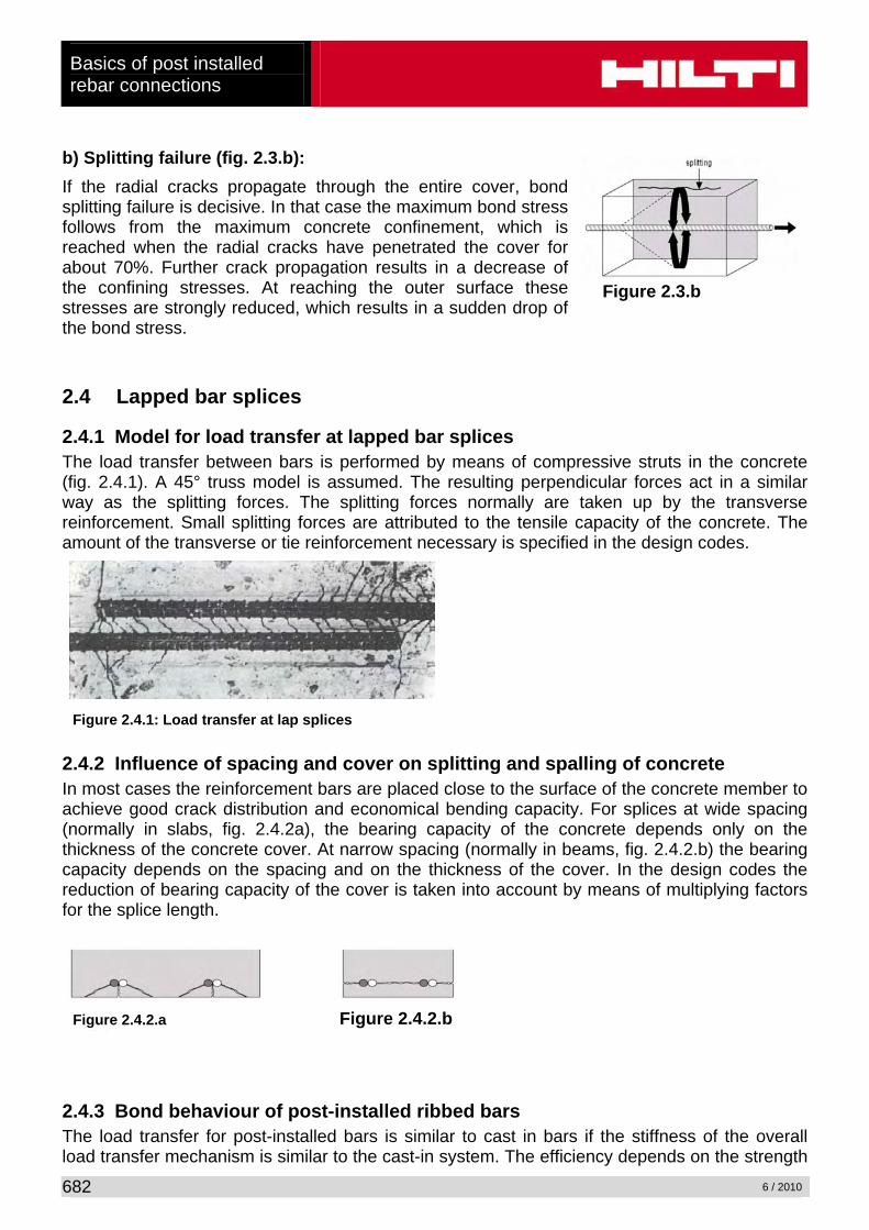
b) Splitting failure (fig. 2.3.b): If the radial cracks propagate through the entire cover, bond splitting failure is decisive. In that case the maximum bond stress follows from the maximum concrete confinement, which is reached when the radial cracks have penetrated the cover for about 70%. Further crack propagation results in a decrease of the confining stresses. At reaching the outer surface these stresses are strongly reduced, which results in a sudden drop of the bond stress.
2.4 Lapped bar splices
2.4.1 Model for load transfer at lapped bar splices The load transfer between bars is performed by means of compressive struts in the concrete (fig. 2.4.1). A 45° truss model is assumed. The resulting perpendicular forces act in a similar way as the splitting forces. The splitting forces normally are taken up by the transverse reinforcement. Small splitting forces are attributed to the tensile capacity of the concrete. The amount of the transverse or tie reinforcement necessary is specified in the design codes.
2.4.2 Influence of spacing and cover on splitting and spalling of concrete In most cases the reinforcement bars are placed close to the surface of the concrete member to achieve good crack distribution and economical bending capacity. For splices at wide spacing (normally in slabs, fig. 2.4.2a), the bearing capacity of the concrete depends only on the thickness of the concrete cover. At narrow spacing (normally in beams, fig. 2.4.2.b) the bearing capacity depends on the spacing and on the thickness of the cover. In the design codes the reduction of bearing capacity of the cover is taken into account by means of multiplying factors for the splice length.
2.4.3 Bond behaviour of post-installed ribbed bars The load transfer for post-installed bars is similar to cast in bars if the stiffness of the overall load transfer mechanism is similar to the cast-in system. The efficiency depends on the strength
Figure 2.4.1: Load transfer at lap splices
Figure 2.3.b

Basics of post installed
rebar connections
6 / 2010
683
of the adhesive mortar against the concentrated load near the ribs and on the capacity of load transfer at the interface of the drilled hole. In many cases the bond values of post-installed bars are higher compared to cast in bars due to better performance of the adhesive mortar. But for small edge distance and/or narrow spacing splitting or spalling forces become decisive due to the low tensile capacity of the concrete.
3 Design basics
3.1 Rebar design methods Post-installed reinforcement connections can basically be designed in compliance with the national codes. Hilti is offering two design methods of which one is based on the Eurocode 2 (EC2 EN 1992-1-1:2004) and the other one on the American Standard (ACI 318-08). The most important characteristics will be explained in the following paragraphs.
3.2 Rebar design according to EC2/ETA approach The new technical report EOTA – TR 023 (Assessment of post-installed rebar connections) establishes a common method to qualify chemical anchors in compliance with EC2. Chemical anchors must comply with a predefined step-diagram for the different concrete classes (Figure 3.2: Chemical anchors without limitations). In general it shall be shown by the tests as described in the TR 023 that the post-installed rebar systems can develop the same design values of bond resistance with the same safety margin as cast-in place rebars according to EC2. In EC2 no requirements for testing are given, but the values for fbd are published. These values are valid for worst case conditions, minimum concrete cover, minimum spacing and minimum transverse reinforcement. In Figure 3.2 a comparison is given which bond resistance in the tests and evaluation according TR 023 have to be reached (on y- axis) to show equivalence with the values fbd (on x- axis). A European Technical Approvals according to the EOTA TR023 allows a design according to EC2. However a design for fire resistance, fatigue, dynamic or seismic loading are excluded. The ETA for Rebar proves that approved systems are robust and durable. Influences of bad cleaning, wet holes, creep, freeze/thaw, durability, corrosion resistance, installation directions are tested within the approval. The post-installed rebar connections assessed according to TR 023 shall be designed as straight cast-in reinforcement according to EC2 using the values of the design bond resistance fbd for deformed bars. The definition of the bond region in EC2 is valid also for post-installed reinforcement. The conditions in EC2 concerning detailing (e.g. concrete cover in respect to bond and corrosion resistance, bar spacing, transverse reinforcement) shall be complied with.

Basics of post installed rebar connections
6 / 2010
684
Figure 3.2: Chemical anchors without limitations from EOTA TR023 The following additional provisions have to be taken into account.
• To prevent damage of the concrete during drilling the following requirements have to be met:
cmin = 30 + 0,06lv ≥ 2ds (mm) for hammer drilled holes, with ds being the diameter of the rebar cmin = 50 + 0,08lv ≥ 2ds (mm) for compressed air drilled holes
The factors 0,06 and 0,08 take into account the possible deviations during the drilling process. This value might be smaller if special drilling aid devices are used.
• Minimum clear spacing between two post-installed rebars a = 40 mm ≥4ds
• To account for potentially different behaviour of post-installed and cast-in rebars in cracked concrete, in general, the minimum embedment length lb,min and l0,min given in EC2 for anchorages and overlap splices shall be increased by a factor of 1,5. This increase may be neglected if it can be shown that the bond strength of the selected post-installed rebars and cast-in rebars in cracked concrete (w = 0,3 mm) is similar. In this case the influence of cracks openings (crack movement tests) can be neglected because for rebar connections several rebars are present (redundant fastening) and not all of the rebars will be situated in a longitudinal crack.
The transfer of shear forces between new and old concrete shall be designed according to EC2. See also paragraph 3.4 “strut-and-tie model”. The reader is referred to the paragraph 4 “EC2 Design” for more detail about this design concept.

Basics of post installed
rebar connections
6 / 2010
685
0.01.02.03.04.05.06.07.08.0
0 10 20 30 40 50 60 70 80 90 100 110
cd
f bd
ACI 318-08 approach
EC2/ETA approach
3.3 N/mm2
6.9 N/mm2
C20/25, Ø = 12 mmcd,min
3.3 Hilti HIT-Rebar design and ACI 318-08 approach The American Standard ACI (American Concrete Institute) 318-08 gives an explicit formula for the design of anchorages and splices that considers splitting and spalling as a function of concrete cover and bar spacing. This function is adapted and extended for post-installed reinforcement for the Hilti HIT-Rebar design concept. The embedment length of an anchorage or splice is defined as a function of concrete strength, the bar diameter, the minimum edge distance or spacing and a coefficient taking into account the transverse reinforcement. In figure 3.3 a typical design bond stress fbd curve as a function of the minimum edge distance/spacing distance, cd is shown for a concrete class C20/25 and for a rebar with a diameter of 12 mm (EC2/ETA approach). In this figure the equivalent design bond stresses resulting from the ACI and the EC2/ETA approaches are plotted to illustrate the two methods (the design bond stresses shown in the figure shall not be used for design purposes). The reduction of anchoring length allowed by ACI and EC2/ETA in specific conditions can be assimilated to an increase of the equivalent design bond stress if cd changes within certain limits. The equivalent design bond stress is defined by an inclined line and it increases with larger values of cd. The increase in the design bond stress is limited by the maximum pull-out bond stress, which is a value which is given by the standards in the case of a cast-in reinforcement. For post-installed reinforcement, the maximum design bond stress is a function of the bonding agent and not necessarily equals that of cast-in bars. Thus, the limitation for bond failure in the code has been replaced by the specific design bond stress of the bonding agent for the specific application conditions and the splitting function has been adapted according to the tests.
cd = min(a/2, c, c1)
Figure 3.3: equivalent design bond stress fbd as a function of cd., derived from reduction of anchoring lenght according to ACI 318-08 and EC2/ETA.

Basics of post installed rebar connections
6 / 2010
686
Interaction of concrete cover and transverse reinforcement (splitting reinforcement) Tests show that transverse reinforcement improves the splitting capacity. Transverse reinforcement can be taken into account by adding a substitute value for the cover. The ACI 318-08 code explicitly takes into account the influence of transverse reinforcement able to prevent splitting by means of the “transverse reinforcement index” Ktr.
ξφ ⋅⋅+
⋅=4
trckbd
Kcff
; barsin -castfor 5.2
Kc ;
ns34.10fA
K tryttrtr ≤
φ+
⋅⋅
⋅=
with: Atr total cross-sectional area of all transverse reinforcement that is within the spacing
s and that crosses the potential plane of splitting through the reinforcement being developed [mm2]
fyt yield strength of transverse reinforcement [N/mm2] s maximum spacing of transverse reinforcement within �b, center to center [mm] n number of bars being developed along the plane of splitting [-] ξ substitute for various adjustment factors
Hilti HIT-Rebar design concept
for 5.2Kc tr ≤φ
+ (post-installed reinforcement and cast-in reinforcement):
4 φγ
trckbd
Kcff
+⋅
⋅=
for 5.2Kc tr >φ
+ (bonded-in bars only):
⎥⎦
⎤⎢⎣
⎡⎟⎟⎠
⎞⎜⎜⎝
⎛−
+⋅+⋅
⋅= 5.275.05.2
4 φγtrck
bdKcf
f
where: fbd design bond strength φ nominal bar size fck characteristic concrete cylinder strength c = cd = min(a/2, c, c1) Ktr see above γ bar size factor For more detailed Information see: Kunz, J.; Münger, F.: “Splitting- and bond failure of post-installed rebar splices and anchoring.”; Bond in Concrete – from research to standards, Proceedings of the 3rd International Symposium held at the Budapest University of Technology and Economics, Budapest, Hungary, 20 to 22 November 2002, p.447 -454. (Copy available from Hilti Technical Service)

Basics of post installed
rebar connections
6 / 2010
687
3.4 Strut-and-tie model The tensile bearing capacity of concrete is very low compared to its compressive strength. For this reason tensile forces are attributed to the steel reinforcement of the concrete member. The reinforcement should be adequately anchored in the nodes {Clause 6.5.3(2), EC2: EN 1992-1-1:2004}. A strut-and-tie model is used to calculate the load path in reinforced concrete members. Where a non-linear strain distribution exists (e.g. supports) strut-and-tie models may be used {Clause 6.5.1(1), EC2: EN 1992-1-1:2004}. Strut-and-tie models consist of struts representing compressive stress fields, of ties representing the reinforcement and of the connecting nodes. The forces in the elements of a strut-and-tie model should be determined by maintaining the equilibrium with the applied loads in ultimate limit state. The ties of a strut-and-tie model should coincide in position and direction with the corresponding reinforcement {Clause 5.6.4, EC2: EN 1992-1-1:2004 Analysis with strut and tie models}.
3.5 Joint to be roughened The model of inclined compressive struts is used to transfer the shear forces through the construction joint at the interface between concrete cast at different times. Therefore a rough interface is required to provide sufficient cohesion in the construction joint {Clause 6.2.5(2), EC2: EN 1992-1-1:2004}. Rough means a surface with at least 3 mm roughness (Rt > 3 mm), achieved by raking, exposing the aggregate or other methods giving an equivalent behaviour.
3.6 Anchorage of reinforcement The reinforcement has to be anchored at places where it is no longer needed. These situations may occur: • when the load path of the tensile force has ended (e.g. support, figure 3.6.a) • at curtailment of reinforcement (see figure 3.6.b) • compression bar anchorage (see figure 3.6.c).
Crack limitation Compression cord and strut (concrete)
Tension cord Tension ties
Joint to be roughened
Figure 3.4: Strut-and-tie-model

Basics of post installed rebar connections
6 / 2010
688
3.7 Lapped splice of reinforcement
Lapped splices are used to achieve continuity in the tensile tie of the truss model at construction joints. The load from one bar to the other is transferred by means of compressive struts in the concrete. A 45°-truss model is assumed.
The resulting splitting force (design bond stress) is limited to a value depending on the surface characteristics of the reinforcement, the tensile strength of the concrete and confinement of surrounding concrete. This depends on sufficient concrete cover, spacing of bar, transverse pressure and by the transverse reinforcement {Clause 6.6, EC2: EN 1992-1-1:2004}.
4 EC2 design
4.1 General The actual position of the reinforcement in the existing structure shall be determined on the basis of the construction documentation and taken into account when designing. The transfer of shear forces between new concrete and existing structure shall be designed according to EC2 EN 1992-1-1:2004. See also paragraph 3.4 “Strut-and-tie model” The joints for concreting must be roughened to at least such an extent that aggregate protrude. See also paragraph 3.5 “Joint to be roughened”. The design of post-installed rebar connections and determination of the internal section forces to be transferred in the construction joint shall be verified in accordance with EC2 EN 1992-1-1:2004. When ascertaining the tensile force in the rebar, allowance shall be made for the statically effective height of the bonded-in reinforcement. See also paragraph 5.2 “Example with overlap joint”
Figure 3.6.c: CompressionFigure 3.6.a:
Support, truss
Figure 3.6.b: Tensile force has ended
Figure 3.7: Lapped splice

Basics of post installed
rebar connections
6 / 2010
689
4.2 Determination of the basic anchorage length The calculation of the required anchorage length shall take into consideration the type of steel and bond properties of the reinforcement. The required basic anchorage length lb,rqd shall be determined in accordance with clause 8.4.3, EC2: EN1992-1-1:2004: lb,rqd = (ds / 4) (σsd / fbd) with: ds = diameter of the rebar σsd = calculated design stress of the rebar
fbd = design value of bond strength according to corresponding ETA, in consideration of the coefficient related to the quality of bond conditions and, of the coefficient related to the bar diameter and of the drilling technique. Refer to the relevant approval or technical data sheet for details.
4.3 Determination of the design anchorage length The required design anchorage length lbd shall be determined in accordance with clause 8.4.4, EC2: EN 1992-1-1:2004: lbd = α1 α2 α3 α4 α5 lb,rqd ≥ lb,min Where α1, α2, α3, α4 and α5 are coefficients given in Table 4.1.
α1 is for the effect of the form of the bars assuming adequate cover (post-installed reinforcement is always straight) α2 is for the effect of concrete minimum cover
( ) 00d2 /ddc0,151α −−=
straight bars; ( )c;c;a/2minc 1d = With no edge distance, α2 = 0,7 if the spacing given in the table below are fulfilled: ds (mm) 8 10 12 14 16 18 20 22 24 25 26 28 30 32 34 36 40 Spacing (mm) 56 70 84 98 112 126 140 154 168 175 182 196 210 224 238 252 280a (mm) 48 60 72 84 96 108 120 132 144 150 156 168 180 192 204 216 240
α3 is for the effect of confinement by transverse reinforcement
α4 is for the influence of one or more welded transverse bars along the design anchorage length lbd. (no welded transverse reinforcement possible with post-installed reinforcement)
α5 is for the effect of the pressure transverse to the plane of splitting along the design anchorage length.
The product (α2α3α5) ≥ 0,7

Basics of post installed rebar connections
6 / 2010
690
lb,rqd = according to section 5.2 lb,min = minimum anchorage length according to clause 8.4.4, EC2: EN 1992-1-1:2004 = max {0.3 lb,rqd; 10ds; 100 mm} under tension = max {0.6 lb,rqd; 10ds; 100 mm} under compression (Please note that the minimum anchorage length may be increased by factor 1,5 according
to EOTA TR023, § 4.2. Refer to the relevant approval or technical data sheet for details.) Table 4.1: Values of α1, α2, α3, α4 and α5 coefficients
Influencing factor Type of anchorage Reinforcement bar In tension In compression
Shape of bars Straight α1 = 1.0 α1 = 1.0 Concrete cover Straight α2 = 1 – 0.15(cd –
ø)/ø ≥ 0.7 ≤ 1.0
α2 = 1.0
Confinement by transverse
reinforcement
Straight α3 = 1 – Kλ ≥ 0.7 ≤ 1.0
α3 = 1.0
Confinement by welded transverse
reinforcement
Straight α4 = 1.0 α4 = 1.0
Confinement by transverse pressure
Straight α5 = 1 – 0.04p ≥ 0.7 ≤ 1.0
-
where: λ = (ΣAst - ΣAst,min)/ As ΣAst cross-sectional area of the transverse reinforcement along the design anchorage length lbd ΣAst,min cross-sectional area of the minimum transverse reinforcement = 0.25 As for beams and 0 for slabs As area of a single anchored bar with maximum bar diameter K values shown in Figure 4.10 p transverse pressure [MPa] at ultimate limit state along lbd
Figure 4.3 : Values of K for beams and slabs
4.4 Overlap joints Forces are transmitted from one bar to another by lapping the bars. The detailing of laps between bars shall be such that:
- the transmission of the forces from one bar to the next is assured - spalling of the concrete in the neighbourhood of the joints does not occur - large cracks which affect the performance of the structure do not occur

Basics of post installed
rebar connections
6 / 2010
691
Laps between bars should not be located in areas of high moments / forces (e.g. plastic hinges) and at any section normally be arranged symmetrically. The arrangement of lapped bars should comply with Figure 4.4. The clear distance between lapped bars should be ≤ 4ø and ≤ 50 mm, otherwise the lap length should be increased by a length equal to the clear space where it exceeds 4ø or 50 mm. Figure 4.4: Adjacent laps The required design lap length l0 shall be determined in accordance with clause 8.7.3, EC2: EN 1992-1-1:2004: l0 = α1 α2 α3 α5 α6 lb,rqd ≥ l0,min with: lb,rqd = according to section 4.2 l0,min = minimum lap length = max {0.3α6 lb,rqd; 15ds; 200 mm} (Please note that the minimum anchorage length may be increased by factor 1,5
according to EOTA TR023, § 4.2. Refer to the relevant approval or technical data sheet for details.)
Values of α1, α2, α3 and α5 may be taken from Table 4.1; however, for the calculation of α3, ΣAst,min should be taken as 1,0 As(σsd/fyd), with As = area of one lapped bar. α6 = (ρ1/25)0.5 but neither not exceeding 1,5 nor less than 1,0, where ρ1 is the percentage of reinforcement lapped within 0.65l0 from the centre of the lap length considered. Values of α6 are given in Table 4.2. (Note: For post-installed rebar applications α6 = 1,5 for the majority of the cases) Table 4.2: Values of the coefficient α6
Percentage of lapped bars relative to the total cross-
section area
< 25% 33% 50% > 50%
α6 1 1,15 1,4 1,5
4.5 Embedment depth for overlap joints Overlap joint for rebars: For calculation of the effective embedment depth of overlap joints the concrete cover at end-face of the post-installed rebar c1 shall be considered: lv ≥ l0 + c1 with: l0 = required lap length according to paragraph 4.4. c1 = concrete cover at end-face of bonded-in rebar. See Figure 4.5
≥ 3ø

Basics of post installed rebar connections
6 / 2010
692
Figure 4.5: Concrete cover c1 If the clear distance between the overlapping bars is greater than 4ds the lap length shall be enlarged by the difference between the actual clear distance and 4ds.
4.6 Concrete cover The minimum concrete cover required for bonded-in rebars is shown in the ETA approvals in relation to the drilling method and the hole tolerance. Furthermore the minimum concrete cover given in clause 4.4.1.2, EC2: EN 1992-1-1: 2004 shall be observed.
4.7 Transverse reinforcement The requirements of transverse reinforcement in the area of the post-installed rebar connection shall comply with clause 8.7.4, EC2: EN 1992-1-1:2004.
4.8 Connection joint In case of a carbonated surface of the existing concrete structure the carbonated layer shall be removed in the area of the post installed rebar connection with a diameter of ds + 60 mm prior to the installation of the new rebar. The depth of concrete to be removed shall correspond to at least the minimum concrete cover for the respective environmental conditions in accordance with EC2: EN 1992-1-1:2004.

Basics of post installed
rebar connections
6 / 2010
693
h = 300 d = 260
h = 300
a1 = 130 al = 260
ln = 6,50 m
5 Design examples
5.1 Anchorage: End support of slab, simply supported • slab: ln = 6,50 m, Qk = 5 kN/m2 ,h = 300 mm,d = 260 mm
wall: h = 300 mm • Concrete strength class: C20/25, dry concrete • Properties of reinforcement: fyk = 500 N/mm2 • Short-term/long-term temperature is 20°C • Fire resistance: F90 (90 minutes) • Loads: Gd = 1,35 x 7,5 = 10,1 kN/m²;
Qd = 1,5 x 5,0 = 7,5 kN/m² ⇒ = 17,6 kN/m²
Structural analysis (design forces) based on leff: MSd = 17,6 x 6,762 / 8 = 100,5 kNm/m VSd = 17,6 x (6,76 / 2) = 59,5 kN/m Bottom reinforcement required at mid span: A s,req = 100,5 x 1,15 / (0,26 x 0,9 x 0,5) = 988 mm²/m ⇒ reinforcement provided: ∅16, s = 200 mm; A s,prov = 1010 mm²/m Bottom reinforcement at support: As,min = 0,4 x 1 x 2,2 x 150 x 1000 / 500 = 264 mm²/m {Clause 7.3.2(2), EC2: EN 1992-1-1:2004} As,min = 0,50 x 988 = 494 mm2/m {Clause 9.3.1.2(1), EC2: EN 1992-1-1:2004} {Clause 9.3.1.1(4), EC 2: EN 1992-1-1:2004} ⇒ As,min = 0,25 x 988 = 247 mm²/m {Clause 9.2.1.4(1), EC2: EN 1992-1-1:2004} As,req = 59,5 x 1 / 0,9 x 1,15 / 0,5 = 152 mm2/m (al =d) {Clause 9.2.1.4(2), EC2: EN 1992-1-1:2004} Decisive is 494 mm²/m ⇒ reinforcement provided: ∅12, s = 200 mm; A s,prov = 565 mm²/m a) Anchorage according to European Technical Approval (ETA) 08/0105, Post-installed rebar connections with Hilti injection mortar HIT-RE 500 Determination of the basic anchorage length The required basic anchorage length lb,rqd shall be determined in accordance with EC2: EN 1992-1-1:2004, section 8.4.3: lb,rqd = (ds / 4) x (σsd / fbd) with: ds = diameter of the rebar = 12 mm σsd = calculated design stress of the rebar = (494 / 565) x (500 / 1,15) = 380 N/mm² fbd = design value of bond strength according to corresponding ETA = 2,3 N/mm² lb,rqd = (12 / 4) x (380 / 2,3) = 496 mm

Basics of post installed rebar connections
6 / 2010
694
Determination of the design anchorage length The required design anchorage length lbd shall be determined in accordance with EC2: EN 1992-1-1:2004, section 8.4.4: lbd = α1 α2 α3 α4 α5 lb,rqd ≥ lb,min with: lb,rqd as above α1 = 1,0 for straight bars α2 = 1 – 0,15(cd – ø)/ø α2 is for the effect of concrete minimum cover ≥ 0,7 ≤ 1,0 a = 200 – 12 = 188 mm a/2 = 94 mm with c1 and c > 94 mm ø = 12 mm α2 = 0,7 Straight bars, cd = min (a/2, c1, c) α3 = 1,0 because of no transverse reinforcement α4 = 1,0 because of no welded transverse reinforcement α5 = 1,0 influence of transverse pressure is neglected in this example lbd = 0,7 x 496 = 347 mm 2/3lbd = 231 mm ⇒ 230 mm lb,min = minimum anchorage length
{Clause 8.4.4(1), EC2: EN 1992-1-1:2004} = max {0,3 x 496; 10 x 12; 100} = 149 mm
b) Anchorage according to Hilti HIT-Rebar design method (splitting): Reinforcement provided: ∅12, s = 200 mm; A s,prov = 565 mm²/m Mortar: Hilti HIT-RE 500 FSd = 494 x 0,5 / 1,15 = 214,8 kN/m Steel: FRd = 5 x (fyk x π x ∅² x ¼) / γs = 245,9 kN/m > 214,8 kN/m ok Concrete (splitting) / Mortar (pull-out): Due to large edge distances in all directions (confined concrete) the failure mode splitting of concrete is not becoming decisive, but the pull out failure mode: fbd = 6.9 N/mm2 FRd = n(lbd x ∅ x π x fbd) = 5(lbd x 12 x π x 6.9) = 214.8 kN/m ⇒ lbd = 165 mm lb,min = 120 mm (10 x ∅) ok Fire resistance: Fire rating class F 90 (90 min.) (design table see paragraph 4.7): FsT,req = 0,6 x 66,1 = 39,7 kN/m = 7,9 kN/bar {Clause 2.4.3 (4) and (5), EC2: ENV 1992-1-2:1995} Hilti HIT-RE 500: ∅12 ⇒ linst = 14,5 cm; Fs,T = 6,02 kN linst = 18 cm; Fs,T = 15,0 kN

Basics of post installed
rebar connections
6 / 2010
695
Intermediate values may be interpolated linearly: linst = 16,5 cm; Fs,T = 11,2 kN/bar > 7,9 kN/bar ⇒ linst = 165 mm Top reinforcement
Top reinforcement at support: Minimum reinforcement: 25% of bottom steel required at mid-span {Clause 9.3.1.2(2), EC2: EN 1992-1-1:2004} As,req = 0,25 x 988 = 247 mm2/m As,min = 0,4 x 1 x 2,2 x 150 x 1000 / 500 = 264 mm2/m {Clause 7.3.2(2), EC2: EN 1992-1-1:2004} Decisive is 264 mm²/m ⇒ reinforcement provided: ∅12, s = 300 mm; A s,prov = 377 mm²/m
a) Anchorage according to European Technical Approval (ETA) 08/0105, Post-installed rebar connections with Hilti injection mortar HIT-RE 500 Determination of the basic anchorage length The required basic anchorage length lb,rqd shall be determined in accordance with EC2: EN 1992-1-1:2004, section 8.4.3: lb,rqd = (ds / 4) x (σsd / fbd) with: ds = diameter of the rebar = 12 mm σsd = calculated design stress of the rebar = (264 / 377) x (500 / 1.15) = 304 N/mm² fbd = design value of bond strength according to corresponding ETA = 2,3 N/mm² lb,rqd = (12 / 4) x (304 / 2,3) = 397 mm Determination of the design anchorage length The required design anchorage length lbd shall be determined in accordance with EC2: EN 1992-1-1:2004, section 8.4.4: lbd = α1 α2 α3 α4 α5 lb,rqd ≥ lb,min with: lb,rqd as above α1 = 1,0 for straight bars α2 = 1 – 0,15(cd – ø)/ø α2 is for the effect of concrete minimum cover ≥ 0,7 ≤ 1,0 a = 300 – 12 = 288 mm a/2 = 144 mm with c1 and c > 144 mm ø = 12 mm ⇒ 0,7 α3 = 1,0 because of no transverse reinforcement α4 = 1,0 because of no welded transverse reinforcement α5 = 1,0 influence of transverse pressure is neglected in this example lbd = 0,7 x 397 = 278 mm ⇒ 280 mm Can be critical with drilling! lb,min = minimum anchorage length {Clause 8.4.4(1), EC2: EN 1992-1-1:2004} = max {0.3 x 397; 10 x 12; 100} = 120 mm ok
h = 300 d = 260
300
a1 = 130 al = 260
ln = 6.50 m

Basics of post installed rebar connections
6 / 2010
696
b) Anchorage according to Hilti HIT Rebar Design Method (CC-Method): Reinforcement provided: ∅12, s = 300 mm; A s,prov = 377 mm2/m Mortar: Hilti HIT-RE 500 A s,min = 264 mm2/m Design Load: FSd = A s,min ⋅ fyk/γs
= 264 x 500 / 1.15 = 114.8 kN/m Fbd = Fsd ⋅ s/1000 = 114.8 kN/m ⋅ 300/1000 = 34.4 kN/bar
Steel Verification: FRd =
⎟⎟⎠
⎞⎜⎜⎝
⎛⋅⋅⋅411000 2φπ
γ s
ykfsmm
= mkNmkN /8.114/9.1634112
15.1500
3001000 2 >=⎟
⎠⎞
⎜⎝⎛ ⋅⋅⋅ π Steel ok!
Combined pull-out and concrete cone failure:
NpsNp
NppRkpRk A
ANN ,0
,
,0,, ψ⋅⋅=
Rk
Mcbdbd
Mp
RkbkpRd
FllN
τφπγ
γτ
φπ⋅⋅⋅
=⇒⋅⋅⋅= 000,
mml bd 9.1271512
1.24.340 =⋅⋅
⋅=
π (τRk from approval ETA-04/0027; table 13)
2
,,0, 115200mmssA NpcrNpcrNp =⋅=
mmsc
mm
hs
NpcrNpcr
efucrRk
Npcr
7.1695.0
7.3839.12734.3395.7
151220
35.7
20
,,
5.0
5.0,
,
==
=⋅≤=⎟⎠⎞
⎜⎝⎛⋅=
⋅≤⎟⎟⎠
⎞⎜⎜⎝
⎛=
τφ
( ) 2,,,
,,
1018204.3393005.0
;
mmscsA
sscc
NpcrNpcrNp
NpcrNpcr
=⋅=+=
<>
0.113.07.0 ,,
, =→≤⋅+= NpsNpcr
Nps cc ψψ
mmA
AFl
NpsNpMp
Rk
Npbdccpobd 5.144
0.11018201.2
1512
1152004.34
,,
0,
)&( =⋅⋅⋅⋅
⋅=
⋅⋅⋅⋅
⋅=
πψγτφπ

Basics of post installed
rebar connections
6 / 2010
697
Concrete cone failure:
NsNc
NccRkcRk A
ANN ,0
,
,0,, ψ⋅⋅=
Mccubeck
bdbdefcubeckcRk
fkF
lhfkN γ⋅⎟⎟
⎠
⎞
⎜⎜
⎝
⎛=⇒=
32
,1
05.1,1
0,
k1 = 7.2 cracked concrete k1 = 10.1 uncracked concrete
mmlbd 1.1165.1251.10
4.34 32
0 =⋅⎟⎟⎠
⎞⎜⎜⎝
⎛
⋅=
mmchs NcrefNcr 15.174;3.3481.11633 ,, ==⋅==
A0
c,N= 121312.9mm2
2,,,
,,
1044903.348300)5.0(
;
mmscsA
sscc
NcrNcrNc
NcrNcr
=⋅=+=
<>
0.113.07.0 ,,
, =→≤⋅+= NpsNpcr
Nps cc ψψ
mmAA
fkFl Mc
NsNc
Nc
cubeck
bdccbd 8.1345.1
0.11
1044909.121312
251.104.341 3
2
,,
,03
2
,1)( =⋅⋅⋅⎟
⎠
⎞⎜⎝
⎛⋅
=⋅⋅⋅⎟⎟
⎠
⎞
⎜⎜
⎝
⎛
⋅= γ
ψ
Splitting failure: only needed if c≥ 1.2ccr,sp and h≥ 2hmin: h/hef = 300mm / 144.5mm = 2.08; ccr,sp = 1.0hef= 144.5mm c > 173.4mm ok hmin = max(hef+30mm; hef+2d0) = max(174.5; 176.5) = 176.5mm h=300mm ≥ 353mm not true, verification needed!!!
sphNs
Nc
NcspRkspRk A
ANN ,,0
,
,0,, ψψ ⋅⋅⋅=
A0
c,N= 83521mm2 scr,sp = 289mm
2,,,
,,
86700289300)5.0(
;
mmscsA
sscc
NcrNcrNc
NcrNcr
=⋅=+=
<>

Basics of post installed rebar connections
6 / 2010
698
0.113.07.0 ,,
, =→≤⋅+= NpsNpcr
Nps cc ψψ
39.1
39.121
42.15.176
300
,
32
min,
323
2
min,
=
=⎟⎟⎠
⎞⎜⎜⎝
⎛≤≤
=⎟⎠⎞
⎜⎝⎛=⎟⎟
⎠
⎞⎜⎜⎝
⎛=
sph
efsph
sph
hh
hh
ψ
ψ
ψ
mmAA
fkFl Mc
sphNsNc
Nc
cubeck
bdspbd 5.805.1
39.10.11
8670083521
251.104.341 3
2
,,,
,03
2
,1)( =⋅
⋅⋅⋅⎟
⎠
⎞⎜⎝
⎛⋅
=⋅⋅
⋅⋅⎟⎟
⎠
⎞
⎜⎜
⎝
⎛
⋅= γ
ψψ
Embedment depth to use: lbd = max[lbd(pp&cc); lbd(cc); lbd(sp)] lbd = 144.5mm ≥ 10ø = 120mm ok
5.2 Example with overlap joint • Bending moment: MSd = 120 kNm/m
slab: h = 300 mm; d = 250 mm, cs = 50 mm • Concrete strength class: C25/30, • Properties of reinforcement: fyk = 500 N/mm² • Fire resistance: F60 (60 minutes),
Light weight plaster for fire protection: 30 mm • top reinforcement: ∅16, s = 150 mm; As,prov = 1340 mm²/m
cover to face c1 = 30 mm • bottom reinforcement: ∅10, s = 200 mm; As,prov = 393 mm²/m • Note: reduced load in cast-in bar due to lever arm: η = 250 / 270 = 0,93
a) Overlap joints according to European Technical Approval (ETA) 08/0105, Post-installed rebar connections with Hilti injection mortar HIT-RE 500 Post-installed reinforcement The required design lap length l0 shall be determined in accordance with EC2: EN 1992-1-1:2004, section 8.7.3: l0 = α1 α2 α3 α5 α6 lb,rqd ≥ l0,min with: lb,rqd the basic anchorage length, lb,rqd = (ds / 4) x (σsd / fbd) ds = diameter of the rebar = 16 mm σsd = calculated design stress of the rebar
d = 250 mm, z ≈ 0,9 x 250 = 225 mm As,req = 120 x 1,15 / (0,225 x 0,5) = 1227 mm2/m σsd = (1227 / 1340) x (500 / 1,15) = 398 N/mm2
fbd = design value of bond strength according to corresponding ETA = 2,7 N/mm2
≥ 10 ∅
d = 250
30
cs = 50 30 h = 300
l0
lv

Basics of post installed
rebar connections
6 / 2010
699
lb,rqd = (16 / 4) x (398 / 2.7) = 590 mm α1 = 1,0 for straight bars α2 = 1 – 0,15(cd – ø)/ø α2 is for the effect of concrete minimum cover ≥ 0,7 ≤ 1,0 c = 50 - 8 = 42 mm cd = 42 mm ø = 16 mm ⇒ 0,76 α3 = 1,0 because of no transverse reinforcement α5 = 1,0 influence of transverse pressure is neglected in this example α6 = 1,5 influence of percentage of lapped bars relative to the total cross-section area {Clause 8.7.3(1), EC2: EN 1992-1-1:2004} l0 = 0,76 x 1,5 x 590 = 673 mm ⇒ 675 mm l0,min = minimum lap length {Clause 8.7.3(1), EC2: EN 1992-1-1:2004}
= max{0.3 x 1.5 x 590; 15 x 16; 200} = 266 mm ok Cast-in reinforcement l0 = α1 α2 α3 α5 α6 lb,rqd ≥ l0,min with: lb,rqd the basic anchorage length, lb,rqd = (ds / 4) x (σsd / fbd) ds = diameter of the rebar = 16 mm σsd = calculated design stress of the rebar
d = 270 mm, z ≈ 0,9 x 270 = 243 mm As,req = 120 x 1,15 / (0,243 x 0,5) = 1136 mm2/m σsd = (1136 / 1340) x (500 / 1,15) = 369 N/mm2
fbd = design value of bond strength according to corresponding ETA = 2,7 N/mm2 lb,rqd = (16 / 4) x (369 / 2.7) = 547 mm α2 = 1 – 0,15(cd – ø)/ø α2 is for the effect of concrete minimum cover ≥ 0,7 ≤ 1,0 c = 30 - 8 = 22 mm cd = 22 mm ø = 16 mm ⇒ 0,94 l0 = 0,94 x 1,5 x 547 = 771 mm ⇒ 770 mm Cast-in reinforcement is decisive! l0,min = minimum lap length {Clause 8.7.3(1), EC2: EN 1992-1-1:2004} = max{0,3 x 1,5 x 547; 15 x 16; 200} = 246 mm ok Embedment depth for overlap joints for rebars: lv ≥ l0 + c1 with: l0 = required lap length = 770 mm (see above) c1 = concrete cover at end face of cast-in rebar = 30 mm lv = 800 mm If the clear distance between the overlapping rebars is greater than 4ds (4 x 16 = 64 mm) the lap length shall be enlarged by the difference between the clear distance and 4ds. Most unfavorable case post-installed rebar is located right in the middle between the cast-in rebars. The clear distance between the overlap is: s22 = a – Ø1/2 – Ø2/2 ; a = (752 + 202)1/2 ⇒ s22 = 77,6 mm – 8 mm – 8 mm = 61,6 mm 61,6 < 64 ⇒ lv = 800 mm

Basics of post installed rebar connections
6 / 2010
700
b) Overlap joints according to Hilti HIT-Rebar design method (splitting): Post-installed reinforcement Reinforcement provided: ∅16, s = 150 mm; A s,prov = 1340 mm²/m Mortar: Hilti HIT-RE 500 FSd = 1340 x 398 = 533,3 kN/m (see above) Steel: FRd = 6,66(fyk x π x ∅2 x ¼) / уs = 582,2 kN/m > 533,3 kN/m ok Mortar (pull-out): fbd = 7,1 N/mm2 Concrete (splitting): (c + Ktr) / ∅ = 3.1 > 2.5 ⇒ fbd is calculated according with: c = min{c, s/2} = 50 mm Ktr = 0 ∅ = 16 mm '
cf = compressive strength of concrete = 25 N/mm2 for C25/30 γ = reinforcement size factor = 0.8 for ∅18
⇒ fbd = 4,6 N/mm2 Due to edge distances (c = 50 mm) and spacing (s = 150 mm) the failure mode splitting of concrete is decisive. α6 = 1,5 ⇒ fbd = 3,1 N/mm2 {Clause 8.7.3(1), EC2: EN 1992-1-1:2004} FRd = n(l0 x ∅ x π x fbd) = 6.66(l0 x 16 x π x 3,1) = 533,3 kN/m ⇒ l0 = 514 mm Cast-in reinforcement (as above) l0 = 770 mm Cast-in reinforcement is decisive! Embedment depth for overlap joints for rebars: lv = 800 mm Fire resistance: Fire rating class F 60 (60 minutes) (design table see paragraph 4.7): Clear concrete cover including light weight plaster: c = 4 + 3 = 7 cm FsT,req = 0.6 x 120 / 0,225 = 320 kN/m = 48 kN/bar {Clause 2.4.3 (4) und (5), EC2: ENV 1992-1-2:1995} τT,req = 48000 / (16 x π x 770) = 1,2 N/mm2 Hilti HIT-RE 500: τT = 1,0 N/mm2 < 1,2 N/mm2 ⇒ increase plaster to 4 cm ⇒ c = 8 cm, τT = 1,4 N/mm2 ok
γφ
4
5.275.05.2'⎥⎦
⎤⎢⎣
⎡⎟⎟⎠
⎞⎜⎜⎝
⎛−
++
=
trc
bd
Kcff
Basics of post installed
rebar connections
6 / 2010
701
6 Corrosion behavior The Swiss Association for Protection against Corrosion (SGK) was given the assignment of evaluating the corrosion behavior of fastenings post-installed in concrete using the Hilti HIT-HY 150, Hilti HIT-HY 150 MAX and Hilti HIT-RE 500 injection systems. Corrosion tests were carried out. The behavior of the two systems had to be evaluated in relation to their use in field practice and compared with the behavior of cast-in reinforcement. The SGK can look back on extensive experience in this field, especially on expertise in the field of repair and maintenance work. The result can be summarized as follows: Hilti HIT-HY 150 + Hilti HIT-HY 150 MAX • The Hilti HIT-HY 150 and Hilti HIT-HY 150 MAX systems in combination with reinforcing bars can be
considered resistant to corrosion when they are used in sound, alkaline concrete. The alkalinity of the adhesive mortar safeguards the initial passivation of the steel. Owing to the porosity of the adhesive mortar, an exchange takes place with the alkaline pore solution of the concrete.
• If rebars are bonded-in into chloride-free concrete using this system, in the event of later chloride exposure, the rates of corrosion are about half those of rebars that are cast-in.
• In concrete containing chlorides, the corrosion behavior of the system corresponds to that of cast-in rebars. Consequently, the use of unprotected steel in concrete exposed to chlorides in the past or possibly in the future is not recommended because corrosion must be expected after only short exposure times.
Hilti HIT-RE 500 • If the Hilti HIT-RE 500 system is used in corrosive surroundings, a sufficiently thick coat of adhesive
significantly increases the time before corrosion starts to attack the bonded-in steel. • The HIT-RE 500 system may be described as resistant to corrosion, even in concrete that is carbonated and
contains chlorides, if a coat thickness of at least 1 mm can be ensured. In this case, the unprotected steel in the concrete joint and in the new concrete is critical.
• If the coat thickness is not ensured, the HIT-RE 500 system may be used only in sound concrete. A rebar may then also be in contact with the wall of the drilled hole. At these points, the steel behaves as though it has a thin coating of epoxy resin.
• In none of the cases investigated did previously rusted steel (without chlorides) show signs of an attack by corrosion, even in concrete containing chlorides.
• Neither during this study an acceleration of corrosion was found at defective points in the adhesive nor was there any reference to this in literature. Even if a macro-element forms, the high resistance to it spreading inhibits a locally increased rate of corrosion.
• Information in reference data corresponds with the results of this study.
7 Fire design If passive fire prevention requirements have to be met, the suitability of rebar connections should be verified additionally to ULS cold design. Large-area building components (walls and floors) can be verified according to tables 1 and 2. The design tables are derived from tests at the University / IBMB Braunschweig following the Standard ISO 834 temperature/time curve. Design for fire resistance is carried out in line with several specific standards. On the following pages only the fire data for Standard according EC2 are given. Details to all available Standards and specific reports are named below the following tables. Note for the following tables 1 to 6: Fs,T = force in bar when exposed to fire. Intermediate values may be interpolated linearly. Extrapolating is not permitted.

Basics of post installed rebar connections
6 / 2010
702
Hilti HIT-HY 150 rebar Bar perpendicular to slab or wall surface exposed to fire
Temperature time curve (acc. ISO 834)
Table 1: Maximum force in rebar in conjuction with HIT-HY 150 as a function of embedment depth for the fire resistance classes F30 to F180 (yield strength fyk = 500 N/mm²) according EC2 a)
Bar ∅ Drill hole ∅ F30 F60 F90 F120 F180
[mm] [mm] linst [mm]
FS,T [kN]
linst [mm]
FS,T [kN]
linst [mm]
FS,T [kN]
linst [mm]
FS,T [kN]
linst [mm]
FS,T [kN]
120 10,6 120 5,0 120 2,8 120 1,9 120 0,7 140 14,1 140 8,4 140 4,5 140 3,3 140 1,5 150 15,6 160 11,9 160 7,9 160 5,2 160 2,7
180 15,4 180 11,4 180 8,6 200 5,3 190 15,6 200 14,9 200 12,1 240 9,6
8 10
210 15,6 220 15,6 280 15,6 150 19,8 150 12,7 150 1,7 150 5,1 150 2,6 160 22,0 160 14,9 160 9,9 160 6,5 160 3,3 180 24,3 180 19,3 180 14,3 180 10,7 180 4,9
200 23,7 200 18,7 200 15,1 220 8,5 210 24,3 220 23,1 220 19,5 260 16,4
10 12
230 24,3 250 24,3 300 24,3 180 31,7 180 23,1 180 17,1 180 12,9 180 5,9 200 35,1 200 28,4 200 22,4 200 18,1 200 8,0
220 33,7 220 27,7 220 23,4 240 14.,4 230 35,1 240 32,9 240 28,7 280 24,9
12 16
250 35,1 270 35,1 320 35,1 210 46,2 210 36,2 210 29,2 210 24,2 210 10,6 220 47,7 220 39,3 220 32,2 220 27,3 220 11,9
240 45,4 240 38,4 240 33,5 240 16,8 250 47,7 260 44,6 260 39,6 280 29,1 270 47,7 280 45,8 320 41,4
14 18
290 47,7 350 47,7 240 62,3 240 51,9 240 43,9 240 38,3 240 19,2
260 59,0 260 51,0 260 45,3 280 33,2 270 62,3 280 58,0 280 52,3 320 47,3 300 62,3 300 59,4 360 61,4
16 20
310 62,3 370 62,3 300 97,4 300 91,3 300 81,3 300 74,3 300 50,3
320 97,4 320 90,1 320 83,0 320 59,1 340 97,4 340 91,8 360 76,7 360 97,4 400 94,3
20 25
410 97,4
linst

Basics of post installed
rebar connections
6 / 2010
703
Bar ∅ Drill hole ∅ F30 F60 F90 F120 F180
[mm] [mm] linst [mm]
FS,T [kN]
linst [mm]
FS,T [kN]
linst [mm]
FS,T [kN]
linst [mm]
FS,T [kN]
linst [mm]
FS,T [kN]
375 152,2 375 152,2 375 142,9 375 134,0 375 104,1 380 145,6 380 136,7 380 106,9 400 152,2 400 147,7 400 117,9 410 152,2 440 139,9
25 32
470 152,2
Remark: The minimum setting depth is related to l > 15 x ds a) For tables according British- and Singapore Standard (resistance class up to F240) see Warringtonfire report WF 166402 or/and IBMB Braunschweig report No 3162/6989 (including supplements). Hilti HIT-HY 150 rebar Bar connection parallel to slab or wall surface exposed to fire Max. bond stress, τT , depending on actual clear concrete cover for classifying the fire resistance. It must be verified that the actual force in the bar during a fire, Fs,T , can be taken up by the bar connection of the selected length, linst. Note: Cold design for ULS is mandatory. Fs, T ≤ (linst – cf)⋅ ∅ ⋅ π ⋅ τT where: (linst – cf) ≥ ls; ls = lap length
∅ = nominal diameter of bar linst – cf = selected overlap joint length; this must be at least ls, but may not be assumed to be more than 80 ∅ τT = bond stress when exposed to fire Temperature time curve (acc. ISO 834)
Table 2: Critical temperature-dependent bond stress, τcrit,T, concerning “overlap joint” for Hilti-HIT-HY 150 injection adhesive in relation to fire resistance class and required minimum concrete coverage c.
Clear concrete cover c Max. bond stress, τT [N/mm²] [mm] F30 F60 F90 F120 F180
20 0,7 0 30 1,4 0,2 40 1,9 0,7
0
50 2,4 1,2 0,4
0
60 2,8 1,7 0,7 0,3 70 4,9 2,2 1,2 0,7
0
linst
c
cf

Basics of post installed rebar connections
6 / 2010
704
Clear concrete cover c Max. bond stress, τT [N/mm²] [mm] F30 F60 F90 F120 F180
80 2,5 1,7 1,0 0,2 90 2,8 2,0 1,5 0,5
100 4,0 2,3 1,9 0,7 110 4,5 2,7 2,3 1,2 120 6,5 2,9 2,6 1,6 130 4,0 2,8 1,9 140 6,5 3,0 2,2 150 4,5 2,3 160 6,5 2,5 170 2,6 180 2,7 190 2,8 200 2,9 210 3,0 220 4,5 230 6,5 240
7,0
7,0 7,0
7,0
7,0 Hilti HIT-HY 150 MAX rebar Bar perpendicular to slab or wall surface exposed to fire
Temperature time curve (acc. ISO 834)
Table 3: Maximum force in rebar in conjuction with HIT-HY 150 MAX as a function of embedment depth for the fire resistance classes F30 to F180 (yield strength fyk = 500 N/mm²) according EC2a).
Bar ∅ Drill hole ∅ Max. Fs,T linst F30 F60 F90 F120 F180 [mm] [mm] [kN] [mm] [kN] [kN] [kN] [kN] [kN]
80 2,18 0,73 0,24 0,05 0 120 8,21 2,90 1,44 0,82 0,18 170 16,2 9,95 5,99 3,69 1,35 210 16,2 13,01 9,52 3,6 230 16,2 13,04 5,74 250 16,2 9,26
8 12 16,2
300 16,2 100 5,87 1,95 0,84 0,4 0 150 16,86 8,06 4,45 2,82 0,96 190 25,3 16,83 11,86 7,65 2,91 230 25,3 20,66 16,29 7,18 260 25,3 22,89 13,77 280 25,3 18,17
10 14 25,3
320 25,3
linst

Basics of post installed
rebar connections
6 / 2010
705
Bar ∅ Drill hole ∅ Max. Fs,T linst F30 F60 F90 F120 F180 [mm] [mm] [kN] [mm] [kN] [kN] [kN] [kN] [kN]
120 12,32 4,35 2,16 1,23 0,27 180 28,15 17,56 11,59 7,14 2,69 220 36,4 28,12 22,15 16,91 6,82 260 36,4 32,7 27,47 16,53 280 36,4 32,75 21,81 300 36,4 27,08
12 16 36,4
340 36,4 140 20,53 8,77 4,74 2,95 0,95 210 42,08 29,72 22,76 16,66 6,3 240 49,6 38,96 32,0 25,89 13,12 280 49,6 44,31 38,21 25,44 300 49,6 44,36 31,6 330 49,6 40,83
14 18 49,6
360 49,6 160 30,5 16,38 9,26 5,77 2,04 240 58,65 44,53 36,57 29,59 15,0 260 64,8 51,56 43,61 36,63 22,04 300 64,8 57,68 50,70 36,11 330 64,8 61,26 46,67 360 64,8 57,22
16 20 64,8
400 64,8 200 55,72 38,06 28,12 19,39 7,22 250 77,71 60,06 50,11 41,39 23,15 310 101,2 86,45 76,5 67,78 49,54 350 101,2 94,09 85,37 67,13 370 101,2 94,16 75,93 390 101,2 84,72
20 25 101,2
430 101,2 250 97,13 75,07 62,46 51,73 28,94 280 113,63 91,56 79,13 68,23 45,43 370 158,1 141,04 128,61 117,71 94,91 410 158,1 150,60 139,70 116,90 430 158,1 150,69 127,90 450 158,1 138,89
25 32 158,1
500 158,1 a) For HIT-HY 150 MAX rebar only the standard acc. EC2 is available (Data also in Warringtonfire report WF 166402 or/and IBMB Braunschweig report No 3884/8246-CM. Hilti HIT-HY 150 MAX rebar Bar connection parallel to slab or wall surface exposed to fire Max. bond stress, τT , depending on actual clear concrete cover for classifying the fire resistance.
It must be verified that the actual force in the bar during a fire, Fs,T , can be taken up by the bar connection of the
selected length, linst. Note: Cold design for ULS is mandatory.
Fs, T ≤ (linst – cf)⋅ ∅ ⋅ π ⋅ τT where: (linst – cf) ≥ ls;
ls = lap length
∅ = nominal diameter of bar
linst – cf = selected overlap joint length; this must be at least ls,
but may not be assumed to be more than 80 ∅
τT = bond stress when exposed to fire

Basics of post installed rebar connections
6 / 2010
706
Table 4: Critical temperature-dependent bond stress, τcrit,T, concerning “overlap joint” for Hilti-HIT-HY 150 MAX injection adhesive in relation to fire resistance class and required minimum concrete coverage c.
Clear concrete cover c Max. bond stress, τT [N/mm²] [mm] F30 F60 F90 F120 F180
30 0,46 35 0,56 40 0,69
0
45 0,84 0,37 50 1,04 0,45 55 1,22 0,53 60 1,47 0,62
0
65 1,85 0,73 0,38 70 0,87 0,46 75 1,02 0,52
0
80 1,21 0,59 0,37 85 1,35 0,67 0,43 90 1,52 0,78 0,52 95 1,74 0,91 0,58
100 2,02 1,07 0,66
0
105 1,21 0,77 0,38 110 1,39 0,91 0,44 115 1,61 1,05 0,48 120 1,89 1,21 0,53 125 2,12 1,37 0,61 130 1,57 0,69 135 1,82 0,75 140 2,13 0,81 145 0,89 150 0,88 155 0,97 160 1,08 165 1,22 170 1,40 175 1,62 180 1,90 185 2,05 190
2,20
2,20
2,20
2,20
2,20 Hilti HIT-RE 500 rebar Bar perpendicular to slab or wall surface exposed to fire
Temperature time curve (acc. ISO 834)
linst

Basics of post installed
rebar connections
6 / 2010
707
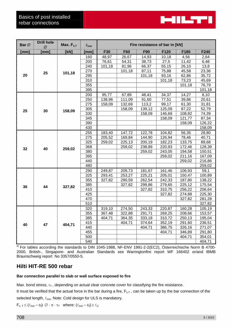
Table 5: Maximum force in rebar in conjuction with HIT-RE 500 as a function of embedment depth for the fire resistance classes F30 to F240 (yield strength fyk = 500 N/mm²) according EC2a).
Bar ∅ Drill hole ∅ Max. Fs,T linst Fire resistance of bar in [kN]
[mm] [mm] [kN] [mm] F30 F60 F90 F120 F180 F240 65 1,38 0,57 0,19 0,05 0 0 80 2,35 1,02 0,47 0,26 0 0 95 3,87 1,68 0,88 0,55 0,12 0 115 7,3 3,07 1,71 1,14 0,44 0,18 150 16,19 8,15 4,59 3,14 1,41 0,8 180 16,19 9,99 6,75 2,94 1,7 205 16,19 12,38 5,08 2,86 220 16,19 6,95 3,82 265 16,19 8,57
8 10 16,19
305 16,19 80 2,94 1,27 0,59 0,33 0 0 100 5,68 2,45 1,31 0,85 0,24 0 120 10,66 4,44 2,48 1,68 0,68 0,31 140 17,57 7,76 4,38 2,99 1,33 0,73 165 25,29 15,06 8,5 5,79 2,58 1,5 195 25,29 17,63 12,18 5,12 2,93 220 25,29 20,66 8,69 4,78 235 25,29 11,8 6,30 280 25,29 13,86
10 12 25,29
320 25,29 95 5,8 2,52 1,32 0,83 0,18 0 120 12,79 5,33 2,97 2,01 0,82 0,37 145 23,16 10,68 6,02 4,12 1,84 1,03 180 36,42 24,29 14,99 10,12 4,41 2,55 210 36,42 27,38 20,65 8,47 4,74 235 36,42 312,01 14,16 7,56 250 36,42 19,13 9,89 295 36,42 21,43
12 16 36,42
335 36,42 110 10,92 4,65 2,55 1,7 0,61 0,20 140 24,60 10,87 6,13 4,19 1,86 1,03 170 39,12 23,50 13,55 9,2 4,07 2,37 195 49.58 35,6 24,69 17,05 7,17 4,10 225 49.58 39,20 31,34 13,48 7,34 250 49.58 43,44 22,32 11,54 265 49.58 29,49 15,00 310 49.58 31,98
14 18 49.58
350 49.58 130 22,59 9,42 5,30 3,61 1,56 0,8 160 39,17 21,33 11,95 8,15 3,65 2,11 190 55,76 37,92 24,45 17,25 7,35 4,22 210 64,75 48,98 36,51 27,53 11,29 6,32 240 64,75 53,10 44,12 20,88 11,04 265 64,75 57,94 33,7 17,14 280 64,75 42,0 22,17 325 64,75 44,84
16 20 64,75
365 64,75
Basics of post installed rebar connections
6 / 2010
708
Bar ∅ Drill hole ∅ Max. Fs,T linst Fire resistance of bar in [kN]
[mm] [mm] [kN] [mm] F30 F60 F90 F120 F180 F240 160 48,97 26,67 14,93 10,18 4,56 2,64 200 76,61 54,31 38,73 27,5 11,42 6,48 240 101,18 81,96 66,37 55,15 26,10 13,8 270 101,18 87,11 75,88 45,58 23,36 295 101,18 93,16 62,86 35,72 310 101,18 73,23 45,69 355 101,18 76,79
20 25 101,18
395 101,18 200 95,77 67,89 48,41 34,37 14,27 8,10 250 138,96 111,09 91,60 77,51 39,86 20,61 275 158,09 132,69 113,2 99,17 61,30 31,81 305 158,09 139,12 125,09 87,22 52,79 330 158,09 146,69 108,82 74,39 345 158,09 121,77 87,34 390 158,09 126,22
25 30 158,09
430 158,09 255 183,40 147,72 122,78 104,82 56,35 28,80 275 205,52 169,84 144,90 126,94 78,46 40,71 325 259,02 225,13 200,19 182,23 133,75 89,68 368 259,02 238,89 220,93 172,46 128,39 380 259,02 243,05 194,58 150,51 395 259,02 211,16 167,09 440 259,02 216,86
32 40 259,02
480 259,02 290 249,87 209,73 181,67 161,46 106,93 59,1 325 293,41 253,27 225,21 205,01 150,47 100,89 355 327,82 290,59 262,54 242,33 187,80 138,22 385 327,82 299,86 279,65 225,12 175,54 410 327,82 310,75 256,22 206,64 425 327,82 274,88 225,30 470 327,82 281,28
36 44 327,82
510 327,82 320 319,10 274,50 243,33 220,87 160,28 105,19 355 367,48 322,88 291,71 269,25 208,66 153,57 385 404,71 364,35 333,18 310,72 250,13 195,04 415 404,71 374,64 352,19 291,60 236,51 440 404,71 386,75 326,16 271,07 455 404,71 346,89 291,80 500 404,71 354,01
40 47 404,71
540 404,71 a) For tables according the standards to DIN 1045-1988, NF-ENV 1991-2-2(EC2), Österreichische Norm B 4700-2000, British-, Singapore- and Australian Standards see Warringtonfire report WF 166402 or/and IBMB Braunschweig report No 3357/0550-5. Hilti HIT-RE 500 rebar Bar connection parallel to slab or wall surface exposed to fire Max. bond stress, τT , depending on actual clear concrete cover for classifying the fire resistance. It must be verified that the actual force in the bar during a fire, Fs,T , can be taken up by the bar connection of the
selected length, linst. Note: Cold design for ULS is mandatory.
Fs, T ≤ (linst – cf)⋅ ∅ ⋅ π ⋅ τT where: (linst – cf) ≥ ls;

Basics of post installed
rebar connections
6 / 2010
709
ls = lap length
∅ = nominal diameter of bar
linst – cf = selected overlap joint length; this must be at least ls,
but may not be assumed to be more than 80 ∅
τT = bond stress when exposed to fire Table 6: Critical temperature-dependent bond stress, τcrit,T, concerning “overlap joint” for Hilti-HIT RE 500 injection adhesive in relation to fire resistance class and required minimum concrete coverage c.
Clear concrete cover c Max. bond stress, τT [N/mm²] [mm] F30 F60 F90 F120 F180 F240
10 0 20 0,494 30 0,665
0
40 0,897 0,481 50 1,209 0,623
0
60 1,630 0,806 0,513
0
70 2,197 1,043 0,655 0,487 80 2,962 1,351 0,835 0,614
0
90 3,992 1,748 1,065 0,775 0,457 100 5,382 2,263 1,358 0,977 0,553
0
110 7,255 2,930 1,733 1,233 0,669 0,469 120 9,780 3,792 2,210 1,556 0,810 0,551 130 4,909 2,818 1,963 0,980 0,647 140 6,355 3,594 2,477 1,185 0,759 150 8,226 4,584 3,125 1,434 0,829 160 10.649 5,846 3,943 1,735 1,047 170 7,456 4,974 2,099 1,230 180 9,510 6,276 2,540 1,445 190 7,918 3,037 1,697 200 9,990 3,718 1,993 210 4,498 2,341 220 5,442 2,749 230 6,584 3,228 240 7,966 3,792 250 9,639 4,453 260 5,230 270 6,143 280 7,214 290 8,473 300 9,951 310
11,00
11,00 11,00
11,00
11,00
11,00

Basics of post installed rebar connections
6 / 2010
710
8 Fatigue of bonded-in reinforcement for joints with predominantly cyclical imposed loading
8.1 General notes For loadbearing elements which are subjected to considerable cyclic stress the bonded-in connections should be designed for fatigue. In that case evidence for fatigue of reinforcing steel bars, concrete and bond should be provided separately. For simple cases it is reasonable to use simplified methods on the safe side. The partial safety factors for loads are specified in the code for reinforced concrete. The partial safety factors for material are specified in Table 4.3. Table 4.3: Partial safety factors for materials subjected to cyclic loading Evidence for concrete bond reinforcing bars (steel) Partial safety factor 1.5 1.8 1.15
8.2 Fatigue of reinforcing bars (steel) The resistance for fatigue of reinforcing bars (steel) is specified in the actual code for reinforced concrete. The behaviour of the steel of reinforcing bars bonded-in by means of Hilti HIT is at least as good as cast-in place reinforcement.
8.3 Fatigue of bond and concrete (simplified approach) As a simple and conservative approach on the safe side evidence for fatigue is proven if the following equation is valid: FSd,fat ≤ NRd ⋅ ffat where: FSd,fat Design value of the anchorage force for the ruling loading model for fatigue. NRd Design resistance for static load of the anchorage (bond and concrete). ffat Reduction factor for fatigue for bond and concrete: ffat = 0.5 If max/min of cycles is known, reduction factors are shown in Figure 4.13.
Diagram for a simplified approach with 2⋅106 cycles (Weyrauch diagram)
Figure 4.13: Reduction factors for fatigue for bond and concrete Hilti design software for rebar connections does also the fatigue design. If the simplified method is not satisfying, additional information using the “Woehler” - lines is available. Ask Hilti Technical Service for the Hilti Guideline: TWU-TPF 06a/02 Hilti HIT-Rebar: Fatigue.
0 0.1 0.2 0.3 0.4 0.5 0.6 0.7 0.8 0.9
1
0 0.2 0.4 0.6 0.8 1
/ N Rd
Sd,fat max / N Rd
Sd,fat min 0
FSd,fat max
FSd,fat min
FSd,fat
time