basisblock mc 3 - leukhardt.de
TRANSCRIPT

Version 2.08.EN of 28.11.2011 page 1 of 12
BasisBlock MC 3
Air-insulated medium voltage switchgear metal enclosed, metal clad type-tested factory-assembled permanent fitting and withdrawable-unit design internal arc fault 12 kV / 24 kV
Leukhardt ...switch to safety!

Version 2.08.EN of 28.11.2011 page 2 of 12
MC3-12 MC3-24
Voltage Rated operating voltage [kV] 12 24 Rated power frequency withstand voltage [kV] 28 50 Rated lightning impulse withstand voltage [kV] 75 125 Short circuit strength Rated short-time withstand current [kA] 40 25 Rated surge withstand strength [kA] 100 65 Rated short-circuit duration [s] 3 3 Arc fault qualificationIAC A FLR acc. to IEC 62271-200, duration 1s [kA] 40 25
Rated current, busbars [A] up to 4000 up to 2000 Rated current, feeders [A] up to 4000 up to 2000 Frequency [Hz] 50/60 50/60 Dimensions [mm] Width 800 1000 Depth 1485 1735 Height 2300 2510 Height with electric-arc-deflector [mm] 2540 2750
Height with absorber [mm] 2800 2870
Height with absorber and exhaust channel [mm] 2988 3060
BasisBlock MC 3
Technical Data
Standards and Regulations IEC 62271-200 ; VDE 0671-200 ; BS EN 62271-200
Ambient air temperature [°C] +5 up to +40Degree of protection IP3XMax. operating height above sea level [m] 1000Colour (higher RAL colours are optional) RAL7035

Version 2.08.EN of 28.11.2011 page 3 of 12
BasisBlock MC 3
Standards and classifications
The switchgear MC3 is used predominantly at the primary distributor-level.It complies to the classifications of IEC 62271-200,VDE 0671-200 and BS EN 62271-200.
Category of operation LSC 2B
Partition-class PM
Accessibility to areas
Busbar area: Tools required
Switchgear room: Interlock-controlled
Connecting area: Tools required
Internal arc classification
The following internal arc qualification has been conducted:
IAC A F L R
IAC = Internal arc classification
A = 300 mm distance of the indicators during control (Installation in closed, electrical place of operation)
F = Indicators during the testing from the front
L = Indicators during the testing from the side
R = Indicators during the testing behind
Isc = Testing current up to 40 kA
t = Arc duration 1s
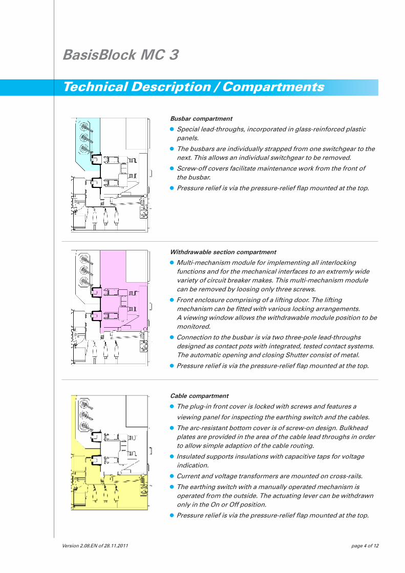
Busbar compartment
Special lead-throughs, incorporated in glass-reinforced plastic panels.
The busbars are individually strapped from one switchgear to the next. This allows an individual switchgear to be removed.
Screw-off covers facilitate maintenance work from the front of the busbar.
Pressure relief is via the pressure-relief flap mounted at the top.
Version 2.08.EN of 28.11.2011 page 4 of 12
Technical Description / Compartments
Withdrawable section compartment
Multi-mechanism module for implementing all interlocking functions and for the mechanical interfaces to an extremly wide variety of circuit breaker makes. This multi-mechanism module can be removed by loosing only three screws.
Front enclosure comprising of a lifting door. The lifting mechanism can be fitted with various locking arrangements. A viewing window allows the withdrawable module position to be monitored.
Connection to the busbar is via two three-pole lead-throughs designed as contact pots with integrated, tested contact systems. The automatic opening and closing Shutter consist of metal.
Pressure relief is via the pressure-relief flap mounted at the top.
BasisBlock MC 3
Cable compartment
The plug-in front cover is locked with screws and features a
viewing panel for inspecting the earthing switch and the cables.
The arc-resistant bottom cover is of screw-on design. Bulkhead plates are provided in the area of the cable lead throughs in order to allow simple adaption of the cable routing.
Insulated supports insulations with capacitive taps for voltage indication.
Current and voltage transformers are mounted on cross-rails.
The earthing switch with a manually operated mechanism is operated from the outside. The actuating lever can be withdrawn only in the On or Off position.
Pressure relief is via the pressure-relief flap mounted at the top.

Version 2.08.EN of 28.11.2011 page 5 of 12
BasisBlock MC 3
Interlocking
The withdrawable module can be moved only if switched OFF regardless of equipment complement.
The actuating lever can be withdrawn only in the end positions after the plug-in module has been fixed in end position.
The control plug can be plugged in only in test position of the plug-in module. The control plug cannot be withdrawn in any other position.
The withdrawable module can be moved to operating position only with the earthing switch switched OFF.
The earthing switch can be switched ON only if the withdrawable module has been withdrawn or is in disconnected position.
A door interlocking can be implemented as an option. With this lock, the front doorof the withdrawa-ble section compartment can be opened only if the withdrawable module is in test position.
Earthing switch
The earthing switch is actuated via an actuating mechanism positioned in the right-hand panel side using a detachable lever.
The detachable lever can be inserted/withdrawn only in ON or OFF position of the earthing switch.
A motor operated mechanism is available. It is mounted directly on the manually operated mechanism.
The manually operated mechanism is retained and emergency manual override is possible.
Secondary functions
The relay box is an independent module.
The auxiliary switches for the test position and the operating position of the withdrawable module are permanently installed.
The control cables are routed upwards from the lower edge of the cell through the lefthand cable shaft. The secondary cabling of the transformers is also routed in metal-clad ducts via the righthand cable shaft.
As a general rule, all commercially available protective relays and components can be used.
Halogen-free materials may be used as an option.
The following components are installed in the front door:
Measuring instruments
Viewing panel for protective relays
Control switches
Mimic diagram with switch position indicator, on separate module
Socket contacts for the capacitive voltage indicator.
Technical Description

Version 2.08.EN of 28.11.2011 page 6 of 12
BasisBlock MC 3
Technical Description
Transport
The MC3 panels are supplied individually. They may be transported with suitable hoists or on steel tubes.
InstallationThe panels must be positioned on an aligned frame and bolted or clamped to the frame. The panels must then be bolted together. The busbars must then be inserted and the ring circuits connected. The arc deflectors when indicated absorbers are supplied separately and adjusted after cubicle assembly.
Function of the trolleyAfter the withdrawable module has been moved to test position and after the withdrawable section compart-ment door has been opened, the trolley must be moved against the cubicle and aligned with a spirit level on the trolley and vertically. The trolley can then be docked. The trolley is then firmly connected to the cell. When the lock release ist operated, the withdrawable module can be pulled onto the trolley. When undocked, the withdrawable module is locked on the trolley.
Function of the shutter lift trolleyThe shutter lift trolley is the lower section of a standard withdrawable module. Two screw-off plates are mounted in the shutter area. These plates can be unscrewed to release each isolating contact bank. The withdrawable module is earthed via the steel rollers.
Accessories
Operating lever for thewithdrawable module
Operating lever for the earthing switch
Trolley for the withdrawable module
Wnding lever for the power circuit-breaker
Any tools for exchanging the fuses
Shutter lifting trolley
FinishAll sheet steel parts, which are not galvanised, are powder coated. Standard colour RAL 7035, slate grey.
Other RAL colours are optional.

PANEL TYPE Rated Current [A]
CIRCuIT-BREAkER PANEL 12 kV up to 3400
CIRCuIT-BREAkER PANEL 24 kV up to 2000
BuSBAR CONNECT. PANEL 12 kV up to 3400 with internal busbar crossover BuSBAR CONNECT. PANEL 24 kV up to 2500 with Duresca-Connection
BuS RISER PANEL up to 3400 Alternatively with:
busbar earthing switch busbar metering module multiple cable connection busbar connection
DISCONNECTING SWITCH up to 800 with disconnecting switch, optional with PANEL HRC fuse-links
DuPLEX PANEL Rated voltage and rated current like above
MOTOR FEEDER PANEL, up to 2500 Outgoing-panel with circuit breakers or COMBINED WITH contactor and busbar-connection to a COMPENSATION PANEL compensation panel mit high-voltage condensers, in modular-system.
Version 2.08.EN of 28.11.2011 page 7 of 12
BasisBlock MC 3
Panel versions 12 kV and 24 kV

Version 2.08.EN of 28.11.2011 page 8 of 12
Graduated System for Triple Operator Safety
Operator Safety
Anyone who has experienced an internal arc test knows what affect the release of a high electrical power supply output during the ignition phase of 1 s has: air is converted to a gas with a temperature of about 4000° C. It is „enriched“ with combustion and vaporisation residue from copper, steel and cast resin.
But where does this explosively emerging mixture (which is expelled upwards via the pressure relief-channels into the switch room) spend itself? Leukhardt offers a concept of graduated operator safety to deal with this problem.
BasisBlock MC 3
Stage 1: Arc deflector The gas mixture is directed to the top at an angle by an arc deflector.
Stage 2: Arc absorber The arc absorber is fitted to the top of the switchpanel, directly above the discharge openings of the three pressure relief channels. The absor-ber (which Leukhardt has registered, pending a patent) cools the gas (approx. temperature 4000° C) down. Pressure is reduced dramatically and the emission of dirt particles and smoke is diminished by about 15 %.
Stage 3: Exhaust channel The residual gas conveys into a horizontal exhaust channel. This exhaust channel is connected to the arc absorber with a flange. This channel conveys the combu-stion by-products directly to the open air.

Version 2.08.EN of 28.11.2011 page 9 of 12
Internal Arc Absorber
Advantages of the internal arc absorber:
In the event of an internal arc being created, the switchroom and the entire building are subject to extreme stress caused by pres-sure, heat and combustion residue. This stress can be relieved to a large degree by the internal arc absorber.
The Leukhardt internal arc absorber is a pressure, temperature and emission reducer which cools gases produced by an internal arc, thus reducing the overpressure reated in the switchgear room
The dirt particle emissions are retained to a great degree in the absorber.
The absorber is a static construction and requires no maintenance.
The absorber reats without hesitation in the event of a malfunction.
BasisBlock MC 3

Version 2.08.EN of 28.11.2011 page 10 of 12
Features
BasisBlock MC3 is a factory assembled, type-tested, metalclad high-voltage switchgear with triple com-partmentalisation and metal shutters in front of the main circuit contacts. It is designed in accordance with the relevant regulations and standards:
The mechanical principle of the plug-in modules complies with the most recent design findings for such appliacations. The plugin module is moved from operating position to disconnected position with only one horizontal swivel movement of 80°.
Switchgear MC3 can be equipped with switchgear devices of a wide variety of makes:
Vacuum power circuitbreakers
Vacuum switches
Vacuum contactors
The cable compartment is accessible from two sides:
from the top, via the detachable multi-mechanism module
from the front, via the detachable steel sheet cover.
Accessibility of the busbar compartment:
from the front, via the detachable steel sheet cover.
The switchgear is suitable forwall and free mounting. All locking devices are of mechanical design. All indicators are of mechanical design. The dielectric strength of the busbars is achieved without use of plastic insulation.
Neighbouring clad-compartments are not impaired in the event of internal arcing. The internal arc cannot re-ignite in neighbouring clad-compartments. The bays are not subject to deformation after an internal arc. This allows bay-by-bay exchange even after an internal arc.
Our standardised arc gas absorber may be used as an option.
Withdrawable section compartment with shutters and multi-mechanism module
This module guarantees all interlocking functions. It also implements the mecha-nical interfaces allowing the use of a wide range of makes of breakers etc.
BasisBlock MC 3

Version 2.08.EN of 28.11.2011 page 11 of 12
BasisBlock MC 3
Universal withdrawable modules for a wide variety of makes
The withdrawable modules are units for accomodating power circuit-breakers, vacuum switches, contactors, fuses and transformers. Regardless of equipment complement, the withdrawable modules have the same design, thus guaranteeing interchangeability. The withdrawable module is moved to the other position with a detachable lever by executing a hori-zontal swivel movement of 80°. The detachable lever can be withdrawn only in the end positions. The withdrawable module is then mechanically interlocked. An interlocking function between withdrawable module and switch compartment door can be imple-mented as an option. As standard, the withdrawable module can be moved from test position to operating position with the door either closed or open. The control plug is arranged above the withdrawable module. It can be plugged in or unplugged only in test position. The withdrawable module can be operated only in operating position when the control plug is plugged in.
The withdrawable module can be withdrawn from the switchgear cubicle only if the trolley has been docked onto the cubicle.
The main circuit contacts feature insulating conduits. These conduits prevent re-ignition at the top contacts towards the busbars in the event of an internal arc in the withdrawable section compartment.The withdrawable modules areguided on steel rollers.
These rollers perform an earth continuity function in the case of shortcircuit currents up to 20 kA. An additional earth contact is fitted for higher short-circuit currents.
The withdrawable module is designed to provide continuous protection against accidental contact with electrically live components.

Version 2.08.EN of 28.11.2011 page 12 of 12
Company Overview
Our Company
The information in this document contains general descriptions of technical possibilities and is therefore not binding. In individual cases the quotation letter or contract conclusion always counts.
Immendingen
Magdeburg
Schwerin
Stuttgart
München
Erfurt Dresden
Berlin
Hannover
Bremen
kiel
Hamburg
Düsseldorf
Frankfurt
Mainz
Saarbrücken
Potsdam
SWITCH TO SAFETY:
Practice, knowledge and experience for our customers
Leukhardt began back in the 1950s with the manufacture of transformer stations and of switchgear for medium and low voltage applications. Nothing has stamped its mark on our development more deeply than the ideas of quality and safety. They provide the orientation for our innovations.
The skill and knowledge of our specialist engineers are the basis for efficient solutions and for a very flexible approach to handling projects.
Head Office Immendingen
Leukhardt Schaltanlagen GmbH
Im Gewerbepark 10 D-78194 Immendingen
Phone: +49 7462 945 61 - 0 Fax: +49 7462 945 61 - 6166
www.leukhardt.de
Leukhardt Schaltanlagen Systemtechnik GmbH
Hagenower Strasse 73 D-19061 Schwerin
Phone: +49 385 399 3560 Fax: +49 385 399 3569
Gustav-Ricker-Strasse 62 D-39120 Magdeburg
Phone +49 391 626 9620 Fax: +49 391 626 9629