bcm50a integrated router configuration advanced€¦ · nortel contivity client termination ......
TRANSCRIPT
BCM50aBCM50a Integrated Router Document Number: N0115791
Document Version: 1.0
Date: September 2006
BCM50a Integrated Router Configuration — Advanced

2
N0115791N0115791
Copyright © Nortel 2005–2006
All rights reserved.The information in this document is subject to change without notice. The statements, configurations, technical data, and recommendations in this document are believed to be accurate and reliable, but are presented without express or implied warranty. Users must take full responsibility for their applications of any products specified in this document. The information in this document is proprietary to Nortel.
Trademarks
Nortel, Nortel (Logo), the Globemark, and This is the way, This is Nortel (Design mark) are trademarks of Nortel.Microsoft, MS, MS-DOS, Windows, and Windows NT are registered trademarks of Microsoft Corporation.All other trademarks and registered trademarks are the property of their respective owners.
3
BCM50a Integrated Router Configuration — Advanced
Contents
Preface . . . . . . . . . . . . . . . . . . . . . . . . . . . . . . . . . . . . . . . . . . . . . . . . . . . . . . 23
Before you begin . . . . . . . . . . . . . . . . . . . . . . . . . . . . . . . . . . . . . . . . . . . . . . . . . . . . . 23Text conventions . . . . . . . . . . . . . . . . . . . . . . . . . . . . . . . . . . . . . . . . . . . . . . . . . . . . . 23Related publications . . . . . . . . . . . . . . . . . . . . . . . . . . . . . . . . . . . . . . . . . . . . . . . . . . . 24Hard-copy technical manuals . . . . . . . . . . . . . . . . . . . . . . . . . . . . . . . . . . . . . . . . . . . . 24How to get help . . . . . . . . . . . . . . . . . . . . . . . . . . . . . . . . . . . . . . . . . . . . . . . . . . . . . . 24
USA and Canada Authorized Distributors . . . . . . . . . . . . . . . . . . . . . . . . . . . . . . . 25Technical Support - GNTS/GNPS . . . . . . . . . . . . . . . . . . . . . . . . . . . . . . . . . . 25Presales Support (CSAN) . . . . . . . . . . . . . . . . . . . . . . . . . . . . . . . . . . . . . . . . 25
EMEA (Europe, Middle East, Africa) . . . . . . . . . . . . . . . . . . . . . . . . . . . . . . . . . . . 25Technical Support - CTAS . . . . . . . . . . . . . . . . . . . . . . . . . . . . . . . . . . . . . . . 25
CALA (Caribbean & Latin America) . . . . . . . . . . . . . . . . . . . . . . . . . . . . . . . . . . . . 26Technical Support - CTAS . . . . . . . . . . . . . . . . . . . . . . . . . . . . . . . . . . . . . . . 26
APAC (Asia Pacific) . . . . . . . . . . . . . . . . . . . . . . . . . . . . . . . . . . . . . . . . . . . . . . . . 26Technical Support - GNTS . . . . . . . . . . . . . . . . . . . . . . . . . . . . . . . . . . . . . . . 26
Chapter 1Getting to know your BCM50a Integrated Router. . . . . . . . . . . . . . . . . . . . 29
Introducing the BCM50a Integrated Router . . . . . . . . . . . . . . . . . . . . . . . . . . . . . . . . . 29Features . . . . . . . . . . . . . . . . . . . . . . . . . . . . . . . . . . . . . . . . . . . . . . . . . . . . . . . . . . . . 29
Physical features . . . . . . . . . . . . . . . . . . . . . . . . . . . . . . . . . . . . . . . . . . . . . . . . . . 30High-speed Internet access . . . . . . . . . . . . . . . . . . . . . . . . . . . . . . . . . . . . . . 30ADSL standards . . . . . . . . . . . . . . . . . . . . . . . . . . . . . . . . . . . . . . . . . . . . . . . 30Networking compatibility . . . . . . . . . . . . . . . . . . . . . . . . . . . . . . . . . . . . . . . . . 31Multiplexing . . . . . . . . . . . . . . . . . . . . . . . . . . . . . . . . . . . . . . . . . . . . . . . . . . . 31Encapsulation . . . . . . . . . . . . . . . . . . . . . . . . . . . . . . . . . . . . . . . . . . . . . . . . . 31Four-Port switch . . . . . . . . . . . . . . . . . . . . . . . . . . . . . . . . . . . . . . . . . . . . . . . 31Autonegotiating 10/100 Mb/s Ethernet LAN . . . . . . . . . . . . . . . . . . . . . . . . . . 32
4 Contents
N0115791
Autosensing 10/100 Mb/s Ethernet LAN . . . . . . . . . . . . . . . . . . . . . . . . . . . . . 32Time and date . . . . . . . . . . . . . . . . . . . . . . . . . . . . . . . . . . . . . . . . . . . . . . . . . 32Reset button . . . . . . . . . . . . . . . . . . . . . . . . . . . . . . . . . . . . . . . . . . . . . . . . . . 32
Nonphysical features . . . . . . . . . . . . . . . . . . . . . . . . . . . . . . . . . . . . . . . . . . . . . . . 32IPSec VPN capability . . . . . . . . . . . . . . . . . . . . . . . . . . . . . . . . . . . . . . . . . . . 32Nortel Contivity Client Termination . . . . . . . . . . . . . . . . . . . . . . . . . . . . . . . . . 32Certificates . . . . . . . . . . . . . . . . . . . . . . . . . . . . . . . . . . . . . . . . . . . . . . . . . . . 33SSH . . . . . . . . . . . . . . . . . . . . . . . . . . . . . . . . . . . . . . . . . . . . . . . . . . . . . . . . 33HTTPS . . . . . . . . . . . . . . . . . . . . . . . . . . . . . . . . . . . . . . . . . . . . . . . . . . . . . . 33Firewall . . . . . . . . . . . . . . . . . . . . . . . . . . . . . . . . . . . . . . . . . . . . . . . . . . . . . . 33Brute force password guessing protection . . . . . . . . . . . . . . . . . . . . . . . . . . . 33Content filtering . . . . . . . . . . . . . . . . . . . . . . . . . . . . . . . . . . . . . . . . . . . . . . . . 34Packet filtering . . . . . . . . . . . . . . . . . . . . . . . . . . . . . . . . . . . . . . . . . . . . . . . . . 34Universal Plug and Play (UPnP) . . . . . . . . . . . . . . . . . . . . . . . . . . . . . . . . . . . 34Call scheduling . . . . . . . . . . . . . . . . . . . . . . . . . . . . . . . . . . . . . . . . . . . . . . . . 34PPPoE . . . . . . . . . . . . . . . . . . . . . . . . . . . . . . . . . . . . . . . . . . . . . . . . . . . . . . . 34Dynamic DNS support . . . . . . . . . . . . . . . . . . . . . . . . . . . . . . . . . . . . . . . . . . . 34IP Multicast . . . . . . . . . . . . . . . . . . . . . . . . . . . . . . . . . . . . . . . . . . . . . . . . . . . 35IP Alias . . . . . . . . . . . . . . . . . . . . . . . . . . . . . . . . . . . . . . . . . . . . . . . . . . . . . . 35Central Network Management . . . . . . . . . . . . . . . . . . . . . . . . . . . . . . . . . . . . 35SNMP . . . . . . . . . . . . . . . . . . . . . . . . . . . . . . . . . . . . . . . . . . . . . . . . . . . . . . . 35Network Address Translation (NAT) . . . . . . . . . . . . . . . . . . . . . . . . . . . . . . . . 35Traffic Redirect . . . . . . . . . . . . . . . . . . . . . . . . . . . . . . . . . . . . . . . . . . . . . . . . 36Port Forwarding . . . . . . . . . . . . . . . . . . . . . . . . . . . . . . . . . . . . . . . . . . . . . . . . 36DHCP (Dynamic Host Configuration Protocol) . . . . . . . . . . . . . . . . . . . . . . . . 36Full network management . . . . . . . . . . . . . . . . . . . . . . . . . . . . . . . . . . . . . . . . 36Logging and tracing . . . . . . . . . . . . . . . . . . . . . . . . . . . . . . . . . . . . . . . . . . . . . 36Upgrade BCM50a Integrated Router Firmware . . . . . . . . . . . . . . . . . . . . . . . 37Embedded FTP and TFTP Servers . . . . . . . . . . . . . . . . . . . . . . . . . . . . . . . . . 37
Applications for the BCM50a Integrated Router . . . . . . . . . . . . . . . . . . . . . . . . . . . . . . 37Secure broadband internet access and VPN . . . . . . . . . . . . . . . . . . . . . . . . . . . . 37
Chapter 2Introducing the SMT . . . . . . . . . . . . . . . . . . . . . . . . . . . . . . . . . . . . . . . . . . . 39
Introduction to the SMT . . . . . . . . . . . . . . . . . . . . . . . . . . . . . . . . . . . . . . . . . . . . . . . . 39
Contents 5
BCM50a Integrated Router Configuration — Advanced
Initial screen . . . . . . . . . . . . . . . . . . . . . . . . . . . . . . . . . . . . . . . . . . . . . . . . . . . . . 39Logging on to the SMT . . . . . . . . . . . . . . . . . . . . . . . . . . . . . . . . . . . . . . . . . . . . . 39
Navigating the SMT interface . . . . . . . . . . . . . . . . . . . . . . . . . . . . . . . . . . . . . . . . . . . . 40Main menu . . . . . . . . . . . . . . . . . . . . . . . . . . . . . . . . . . . . . . . . . . . . . . . . . . . . . . . 41
Changing the system password . . . . . . . . . . . . . . . . . . . . . . . . . . . . . . . . . . . . . . . . . . 43SMT menus at a glance . . . . . . . . . . . . . . . . . . . . . . . . . . . . . . . . . . . . . . . . . . . . . 44
SMT menu 1 - general setup . . . . . . . . . . . . . . . . . . . . . . . . . . . . . . . . . . . . . 45
Introduction to general setup . . . . . . . . . . . . . . . . . . . . . . . . . . . . . . . . . . . . . . . . . . . . 45Configuring general setup . . . . . . . . . . . . . . . . . . . . . . . . . . . . . . . . . . . . . . . . . . . . . . 45
Configuring dynamic DNS . . . . . . . . . . . . . . . . . . . . . . . . . . . . . . . . . . . . . . . . . . . 48
Chapter 3WAN Setup . . . . . . . . . . . . . . . . . . . . . . . . . . . . . . . . . . . . . . . . . . . . . . . . . . . 53
Introduction to WAN setup . . . . . . . . . . . . . . . . . . . . . . . . . . . . . . . . . . . . . . . . . . . . . . 53WAN setup . . . . . . . . . . . . . . . . . . . . . . . . . . . . . . . . . . . . . . . . . . . . . . . . . . . . . . . . . . 53Traffic redirect setup . . . . . . . . . . . . . . . . . . . . . . . . . . . . . . . . . . . . . . . . . . . . . . . . . . 55
Chapter 4LAN setup . . . . . . . . . . . . . . . . . . . . . . . . . . . . . . . . . . . . . . . . . . . . . . . . . . . . 57
Introduction to LAN setup . . . . . . . . . . . . . . . . . . . . . . . . . . . . . . . . . . . . . . . . . . . . . . . 57Accessing the LAN menus . . . . . . . . . . . . . . . . . . . . . . . . . . . . . . . . . . . . . . . . . . . . . . 57LAN port filter setup . . . . . . . . . . . . . . . . . . . . . . . . . . . . . . . . . . . . . . . . . . . . . . . . . . . 57
TCP/IP and DHCP ethernet setup menu . . . . . . . . . . . . . . . . . . . . . . . . . . . . . . . . 58IP Alias Setup . . . . . . . . . . . . . . . . . . . . . . . . . . . . . . . . . . . . . . . . . . . . . . . . . . . . 61
Chapter 5Internet access. . . . . . . . . . . . . . . . . . . . . . . . . . . . . . . . . . . . . . . . . . . . . . . . 65
Internet access configuration . . . . . . . . . . . . . . . . . . . . . . . . . . . . . . . . . . . . . . . . . . . . 65Basic setup complete . . . . . . . . . . . . . . . . . . . . . . . . . . . . . . . . . . . . . . . . . . . . . . . . . . 67
Chapter 6Remote Node setup . . . . . . . . . . . . . . . . . . . . . . . . . . . . . . . . . . . . . . . . . . . . 69
Introduction to Remote Node setup . . . . . . . . . . . . . . . . . . . . . . . . . . . . . . . . . . . . . . . 69Outgoing Authentication Protocol . . . . . . . . . . . . . . . . . . . . . . . . . . . . . . . . . . . . . 69Nailed-Up Connection . . . . . . . . . . . . . . . . . . . . . . . . . . . . . . . . . . . . . . . . . . . . . . 70
6 Contents
N0115791
Remote Node setup . . . . . . . . . . . . . . . . . . . . . . . . . . . . . . . . . . . . . . . . . . . . . . . . . . . 70Remote Node profile . . . . . . . . . . . . . . . . . . . . . . . . . . . . . . . . . . . . . . . . . . . . . . . 70Encapsulation and Multiplexing scenarios . . . . . . . . . . . . . . . . . . . . . . . . . . . . . . . 71
Edit IP/Bridge . . . . . . . . . . . . . . . . . . . . . . . . . . . . . . . . . . . . . . . . . . . . . . . . . . . . . . . . 74Remote Node filter . . . . . . . . . . . . . . . . . . . . . . . . . . . . . . . . . . . . . . . . . . . . . . . . . . . . 77Editing ATM Layer Options . . . . . . . . . . . . . . . . . . . . . . . . . . . . . . . . . . . . . . . . . . . . . 79
VC-based Multiplexing (non-PPP Encapsulation) . . . . . . . . . . . . . . . . . . . . . . . . . 79LLC-based Multiplexing or PPP Encapsulation . . . . . . . . . . . . . . . . . . . . . . . . . . . 79Advance Setup Options . . . . . . . . . . . . . . . . . . . . . . . . . . . . . . . . . . . . . . . . . . . . . 80
Chapter 7IP Static Route Setup. . . . . . . . . . . . . . . . . . . . . . . . . . . . . . . . . . . . . . . . . . . 83
IP Static Route Setup . . . . . . . . . . . . . . . . . . . . . . . . . . . . . . . . . . . . . . . . . . . . . . . . . . 83
Chapter 8Dial-in User Setup . . . . . . . . . . . . . . . . . . . . . . . . . . . . . . . . . . . . . . . . . . . . . 87
Dial-in User Setup . . . . . . . . . . . . . . . . . . . . . . . . . . . . . . . . . . . . . . . . . . . . . . . . . . . . 87
Chapter 9Network Address Translation (NAT) . . . . . . . . . . . . . . . . . . . . . . . . . . . . . . 89
Using NAT . . . . . . . . . . . . . . . . . . . . . . . . . . . . . . . . . . . . . . . . . . . . . . . . . . . . . . . . . . 89SUA (Single User Account) Versus NAT . . . . . . . . . . . . . . . . . . . . . . . . . . . . . . . . 89Applying NAT . . . . . . . . . . . . . . . . . . . . . . . . . . . . . . . . . . . . . . . . . . . . . . . . . . . . . 89
NAT setup . . . . . . . . . . . . . . . . . . . . . . . . . . . . . . . . . . . . . . . . . . . . . . . . . . . . . . . . . . 92Address Mapping Sets . . . . . . . . . . . . . . . . . . . . . . . . . . . . . . . . . . . . . . . . . . . . . 92
SUA Address Mapping Set . . . . . . . . . . . . . . . . . . . . . . . . . . . . . . . . . . . . . . . 93User-Defined Address Mapping Sets . . . . . . . . . . . . . . . . . . . . . . . . . . . . . . . 95Ordering your rules . . . . . . . . . . . . . . . . . . . . . . . . . . . . . . . . . . . . . . . . . . . . . 96
Configuring a server behind NAT . . . . . . . . . . . . . . . . . . . . . . . . . . . . . . . . . . . . . . . . . 99General NAT examples . . . . . . . . . . . . . . . . . . . . . . . . . . . . . . . . . . . . . . . . . . . . . . . 103
Internet access only . . . . . . . . . . . . . . . . . . . . . . . . . . . . . . . . . . . . . . . . . . . . . . . 103Example 2: Internet access with an inside server . . . . . . . . . . . . . . . . . . . . . . . . 105Example 3: Multiple public IP addresses with inside servers . . . . . . . . . . . . . . . 106
Configuring Trigger Port forwarding . . . . . . . . . . . . . . . . . . . . . . . . . . . . . . . . . . . . . 111
Contents 7
BCM50a Integrated Router Configuration — Advanced
Chapter 10Introducing the firewall . . . . . . . . . . . . . . . . . . . . . . . . . . . . . . . . . . . . . . . . 115
Using SMT menus . . . . . . . . . . . . . . . . . . . . . . . . . . . . . . . . . . . . . . . . . . . . . . . . . . . 115Activating the firewall . . . . . . . . . . . . . . . . . . . . . . . . . . . . . . . . . . . . . . . . . . . . . . 115
Chapter 11Filter configuration . . . . . . . . . . . . . . . . . . . . . . . . . . . . . . . . . . . . . . . . . . . 117
Introduction to filters . . . . . . . . . . . . . . . . . . . . . . . . . . . . . . . . . . . . . . . . . . . . . . . . . . 117Filter Structure . . . . . . . . . . . . . . . . . . . . . . . . . . . . . . . . . . . . . . . . . . . . . . . . . . . 118
Configuring a Filter Set . . . . . . . . . . . . . . . . . . . . . . . . . . . . . . . . . . . . . . . . . . . . . . . 120Configuring a Filter Rule . . . . . . . . . . . . . . . . . . . . . . . . . . . . . . . . . . . . . . . . . . . 123Configuring a TCP/IP Filter Rule . . . . . . . . . . . . . . . . . . . . . . . . . . . . . . . . . . . . . 123Configuring a Generic Filter Rule . . . . . . . . . . . . . . . . . . . . . . . . . . . . . . . . . . . . 128
Example Filter . . . . . . . . . . . . . . . . . . . . . . . . . . . . . . . . . . . . . . . . . . . . . . . . . . . . . . 130Filter Types and NAT . . . . . . . . . . . . . . . . . . . . . . . . . . . . . . . . . . . . . . . . . . . . . . . . . 133Firewall Versus Filters . . . . . . . . . . . . . . . . . . . . . . . . . . . . . . . . . . . . . . . . . . . . . . . . 134Applying a Filter . . . . . . . . . . . . . . . . . . . . . . . . . . . . . . . . . . . . . . . . . . . . . . . . . . . . 134
Applying LAN Filters . . . . . . . . . . . . . . . . . . . . . . . . . . . . . . . . . . . . . . . . . . . . . . 135Applying Remote Node Filters . . . . . . . . . . . . . . . . . . . . . . . . . . . . . . . . . . . . . . . 135
Chapter 12SNMP Configuration . . . . . . . . . . . . . . . . . . . . . . . . . . . . . . . . . . . . . . . . . . 137
SNMP Configuration . . . . . . . . . . . . . . . . . . . . . . . . . . . . . . . . . . . . . . . . . . . . . . . . . 137SNMP Traps . . . . . . . . . . . . . . . . . . . . . . . . . . . . . . . . . . . . . . . . . . . . . . . . . . . . . . . . 139
Chapter 13System security . . . . . . . . . . . . . . . . . . . . . . . . . . . . . . . . . . . . . . . . . . . . . . 141
System security . . . . . . . . . . . . . . . . . . . . . . . . . . . . . . . . . . . . . . . . . . . . . . . . . . . . . 141System password . . . . . . . . . . . . . . . . . . . . . . . . . . . . . . . . . . . . . . . . . . . . . . . . 141Configuring external RADIUS server . . . . . . . . . . . . . . . . . . . . . . . . . . . . . . . . . . 142
Chapter 14System information and diagnosis . . . . . . . . . . . . . . . . . . . . . . . . . . . . . . 145
Introduction to System Status . . . . . . . . . . . . . . . . . . . . . . . . . . . . . . . . . . . . . . . . . . 145System Status . . . . . . . . . . . . . . . . . . . . . . . . . . . . . . . . . . . . . . . . . . . . . . . . . . . . . . 146
8 Contents
N0115791
System information and console port speed . . . . . . . . . . . . . . . . . . . . . . . . . . . . . . . 148System Information . . . . . . . . . . . . . . . . . . . . . . . . . . . . . . . . . . . . . . . . . . . . . . . 149Console port speed . . . . . . . . . . . . . . . . . . . . . . . . . . . . . . . . . . . . . . . . . . . . . . . 151
Log and trace . . . . . . . . . . . . . . . . . . . . . . . . . . . . . . . . . . . . . . . . . . . . . . . . . . . . . . . 151Syslog logging . . . . . . . . . . . . . . . . . . . . . . . . . . . . . . . . . . . . . . . . . . . . . . . . . . . 152
CDR . . . . . . . . . . . . . . . . . . . . . . . . . . . . . . . . . . . . . . . . . . . . . . . . . . . . . . . 153Packet triggered . . . . . . . . . . . . . . . . . . . . . . . . . . . . . . . . . . . . . . . . . . . . . . 154Filter log . . . . . . . . . . . . . . . . . . . . . . . . . . . . . . . . . . . . . . . . . . . . . . . . . . . . 154PPP log . . . . . . . . . . . . . . . . . . . . . . . . . . . . . . . . . . . . . . . . . . . . . . . . . . . . 155Firewall log . . . . . . . . . . . . . . . . . . . . . . . . . . . . . . . . . . . . . . . . . . . . . . . . . . 156
Call-Triggering packet . . . . . . . . . . . . . . . . . . . . . . . . . . . . . . . . . . . . . . . . . . . . . 156WAN DHCP . . . . . . . . . . . . . . . . . . . . . . . . . . . . . . . . . . . . . . . . . . . . . . . . . . . . . 158
Chapter 15Firmware and configuration file maintenance . . . . . . . . . . . . . . . . . . . . . 161
Filename conventions . . . . . . . . . . . . . . . . . . . . . . . . . . . . . . . . . . . . . . . . . . . . . . . . 161Backup configuration . . . . . . . . . . . . . . . . . . . . . . . . . . . . . . . . . . . . . . . . . . . . . . . . . 162
Backup configuration . . . . . . . . . . . . . . . . . . . . . . . . . . . . . . . . . . . . . . . . . . . . . . 163Using the FTP command from the command line . . . . . . . . . . . . . . . . . . . . . . . . 163Example of FTP commands from the command line . . . . . . . . . . . . . . . . . . . . . . 164GUI-based FTP clients . . . . . . . . . . . . . . . . . . . . . . . . . . . . . . . . . . . . . . . . . . . . 164TFTP and FTP over WAN Management Limitations . . . . . . . . . . . . . . . . . . . . . . 164Backup configuration using TFTP . . . . . . . . . . . . . . . . . . . . . . . . . . . . . . . . . . . . 165TFTP command example . . . . . . . . . . . . . . . . . . . . . . . . . . . . . . . . . . . . . . . . . . 166GUI-based TFTP clients . . . . . . . . . . . . . . . . . . . . . . . . . . . . . . . . . . . . . . . . . . . 166
Restore configuration . . . . . . . . . . . . . . . . . . . . . . . . . . . . . . . . . . . . . . . . . . . . . . . . . 167Restore Using FTP . . . . . . . . . . . . . . . . . . . . . . . . . . . . . . . . . . . . . . . . . . . . . . . 167Restore using FTP session example . . . . . . . . . . . . . . . . . . . . . . . . . . . . . . . . . . 169
Uploading Firmware and Configuration Files . . . . . . . . . . . . . . . . . . . . . . . . . . . . . . . 169Firmware file upload . . . . . . . . . . . . . . . . . . . . . . . . . . . . . . . . . . . . . . . . . . . . . . 169Configuration file upload . . . . . . . . . . . . . . . . . . . . . . . . . . . . . . . . . . . . . . . . . . . 170FTP file upload command from the DOS prompt example . . . . . . . . . . . . . . . . . 171FTP Session Example of Firmware File Upload . . . . . . . . . . . . . . . . . . . . . . . . . 172TFTP file upload . . . . . . . . . . . . . . . . . . . . . . . . . . . . . . . . . . . . . . . . . . . . . . . . . 172TFTP upload command example . . . . . . . . . . . . . . . . . . . . . . . . . . . . . . . . . . . . 173
Contents 9
BCM50a Integrated Router Configuration — Advanced
Chapter 16System Maintenance menus 8 to 10 . . . . . . . . . . . . . . . . . . . . . . . . . . . . . 175
Command Interpreter mode . . . . . . . . . . . . . . . . . . . . . . . . . . . . . . . . . . . . . . . . . . . . 175Command syntax . . . . . . . . . . . . . . . . . . . . . . . . . . . . . . . . . . . . . . . . . . . . . . . . . 176Command usage . . . . . . . . . . . . . . . . . . . . . . . . . . . . . . . . . . . . . . . . . . . . . . . . . 177
Call control support . . . . . . . . . . . . . . . . . . . . . . . . . . . . . . . . . . . . . . . . . . . . . . . . . . 177Budget management . . . . . . . . . . . . . . . . . . . . . . . . . . . . . . . . . . . . . . . . . . . . . . 178Call History . . . . . . . . . . . . . . . . . . . . . . . . . . . . . . . . . . . . . . . . . . . . . . . . . . . . . 180
Time and Date setting . . . . . . . . . . . . . . . . . . . . . . . . . . . . . . . . . . . . . . . . . . . . . . . . 181Resetting the Time . . . . . . . . . . . . . . . . . . . . . . . . . . . . . . . . . . . . . . . . . . . . . . . 184
Chapter 17Remote Management. . . . . . . . . . . . . . . . . . . . . . . . . . . . . . . . . . . . . . . . . . 185
Remote Management . . . . . . . . . . . . . . . . . . . . . . . . . . . . . . . . . . . . . . . . . . . . . . . . . 185Remote Management Limitations . . . . . . . . . . . . . . . . . . . . . . . . . . . . . . . . . . . . 187
Chapter 18Call scheduling . . . . . . . . . . . . . . . . . . . . . . . . . . . . . . . . . . . . . . . . . . . . . . 189
Introduction . . . . . . . . . . . . . . . . . . . . . . . . . . . . . . . . . . . . . . . . . . . . . . . . . . . . . . . . 189
Appendix ASetting up your computer IP address . . . . . . . . . . . . . . . . . . . . . . . . . . . . 193
Windows 95/98/Me . . . . . . . . . . . . . . . . . . . . . . . . . . . . . . . . . . . . . . . . . . . . . . . . . . . 193Installing components . . . . . . . . . . . . . . . . . . . . . . . . . . . . . . . . . . . . . . . . . . 194Configuring . . . . . . . . . . . . . . . . . . . . . . . . . . . . . . . . . . . . . . . . . . . . . . . . . . 195Verifying Settings . . . . . . . . . . . . . . . . . . . . . . . . . . . . . . . . . . . . . . . . . . . . . 196
Windows 2000/NT/XP . . . . . . . . . . . . . . . . . . . . . . . . . . . . . . . . . . . . . . . . . . . . . . . . 197Verifying Settings . . . . . . . . . . . . . . . . . . . . . . . . . . . . . . . . . . . . . . . . . . . . . 201
Macintosh OS 8/9 . . . . . . . . . . . . . . . . . . . . . . . . . . . . . . . . . . . . . . . . . . . . . . . . . . . . 201Verifying Settings . . . . . . . . . . . . . . . . . . . . . . . . . . . . . . . . . . . . . . . . . . . . . 202
Macintosh OS X . . . . . . . . . . . . . . . . . . . . . . . . . . . . . . . . . . . . . . . . . . . . . . . . . . . . . 203Verifying settings . . . . . . . . . . . . . . . . . . . . . . . . . . . . . . . . . . . . . . . . . . . . . . 204
Appendix B
10 Contents
N0115791
Triangle Route . . . . . . . . . . . . . . . . . . . . . . . . . . . . . . . . . . . . . . . . . . . . . . . 205
The Ideal Setup . . . . . . . . . . . . . . . . . . . . . . . . . . . . . . . . . . . . . . . . . . . . . . . . . . . . . 205The Triangle Route Problem . . . . . . . . . . . . . . . . . . . . . . . . . . . . . . . . . . . . . . . . . . . 205The Triangle Route Solutions . . . . . . . . . . . . . . . . . . . . . . . . . . . . . . . . . . . . . . . . . . . 206IP aliasing . . . . . . . . . . . . . . . . . . . . . . . . . . . . . . . . . . . . . . . . . . . . . . . . . . . . . . . . . . 206
Appendix CImporting certificates . . . . . . . . . . . . . . . . . . . . . . . . . . . . . . . . . . . . . . . . . 209
Import BCM50a Integrated Router certificates into Netscape Navigator . . . . . . . . . . 209Importing the BCM50a Integrated Router Certificate into Internet Explorer . . . . . . . . 210Enrolling and Importing SSL Client Certificates . . . . . . . . . . . . . . . . . . . . . . . . . . . . . 215Using a certificate when accessing the BCM50a Integrated Router example . . . . . . 223
Appendix DPPPoE . . . . . . . . . . . . . . . . . . . . . . . . . . . . . . . . . . . . . . . . . . . . . . . . . . . . . . 225
PPPoE in action . . . . . . . . . . . . . . . . . . . . . . . . . . . . . . . . . . . . . . . . . . . . . . . . . . . . . 225Benefits of PPPoE . . . . . . . . . . . . . . . . . . . . . . . . . . . . . . . . . . . . . . . . . . . . . . . . . . . 225Traditional dial-up scenario . . . . . . . . . . . . . . . . . . . . . . . . . . . . . . . . . . . . . . . . . . . . 225How PPPoE works . . . . . . . . . . . . . . . . . . . . . . . . . . . . . . . . . . . . . . . . . . . . . . . . . . . 226BCM50a Integrated Router as a PPPoE client . . . . . . . . . . . . . . . . . . . . . . . . . . . . . 226
Appendix EHardware specifications . . . . . . . . . . . . . . . . . . . . . . . . . . . . . . . . . . . . . . . 229
Cable pin assignments . . . . . . . . . . . . . . . . . . . . . . . . . . . . . . . . . . . . . . . . . . . . . . . . 229
Appendix FIP subnetting . . . . . . . . . . . . . . . . . . . . . . . . . . . . . . . . . . . . . . . . . . . . . . . . 231
IP addressing . . . . . . . . . . . . . . . . . . . . . . . . . . . . . . . . . . . . . . . . . . . . . . . . . . . . . . . 231IP classes . . . . . . . . . . . . . . . . . . . . . . . . . . . . . . . . . . . . . . . . . . . . . . . . . . . . . . . . . . 231Subnet masks . . . . . . . . . . . . . . . . . . . . . . . . . . . . . . . . . . . . . . . . . . . . . . . . . . . . . . 233Subnetting . . . . . . . . . . . . . . . . . . . . . . . . . . . . . . . . . . . . . . . . . . . . . . . . . . . . . . . . . 233Example: two subnets . . . . . . . . . . . . . . . . . . . . . . . . . . . . . . . . . . . . . . . . . . . . . . . . 234Example: four subnets . . . . . . . . . . . . . . . . . . . . . . . . . . . . . . . . . . . . . . . . . . . . . . . . 236Example: eight subnets . . . . . . . . . . . . . . . . . . . . . . . . . . . . . . . . . . . . . . . . . . . . . . . 237Subnetting with Class A and Class B networks. . . . . . . . . . . . . . . . . . . . . . . . . . . . . 238
Contents 11
BCM50a Integrated Router Configuration — Advanced
Appendix GCommand Interpreter . . . . . . . . . . . . . . . . . . . . . . . . . . . . . . . . . . . . . . . . . 241
Command Syntax . . . . . . . . . . . . . . . . . . . . . . . . . . . . . . . . . . . . . . . . . . . . . . . . . . . . 241Command usage . . . . . . . . . . . . . . . . . . . . . . . . . . . . . . . . . . . . . . . . . . . . . . . . . . . . 241Sys commands . . . . . . . . . . . . . . . . . . . . . . . . . . . . . . . . . . . . . . . . . . . . . . . . . . . . . . 242Exit Command . . . . . . . . . . . . . . . . . . . . . . . . . . . . . . . . . . . . . . . . . . . . . . . . . . . . . . 249Ethernet Commands . . . . . . . . . . . . . . . . . . . . . . . . . . . . . . . . . . . . . . . . . . . . . . . . . 249IP commands . . . . . . . . . . . . . . . . . . . . . . . . . . . . . . . . . . . . . . . . . . . . . . . . . . . . . . . 250IPSec commands . . . . . . . . . . . . . . . . . . . . . . . . . . . . . . . . . . . . . . . . . . . . . . . . . . . . 257WAN Commands . . . . . . . . . . . . . . . . . . . . . . . . . . . . . . . . . . . . . . . . . . . . . . . . . . . . 266Sys firewall commands . . . . . . . . . . . . . . . . . . . . . . . . . . . . . . . . . . . . . . . . . . . . . . . 268Bandwidth management commands . . . . . . . . . . . . . . . . . . . . . . . . . . . . . . . . . . . . . 269Certificates commands . . . . . . . . . . . . . . . . . . . . . . . . . . . . . . . . . . . . . . . . . . . . . . . . 272
Appendix HNetBIOS filter commands . . . . . . . . . . . . . . . . . . . . . . . . . . . . . . . . . . . . . . 279
Introduction . . . . . . . . . . . . . . . . . . . . . . . . . . . . . . . . . . . . . . . . . . . . . . . . . . . . . . . . 279Display NetBIOS filter settings . . . . . . . . . . . . . . . . . . . . . . . . . . . . . . . . . . . . . . . . . . 280NetBIOS filter configuration . . . . . . . . . . . . . . . . . . . . . . . . . . . . . . . . . . . . . . . . . . . . 280
Example commands . . . . . . . . . . . . . . . . . . . . . . . . . . . . . . . . . . . . . . . . . . . . . . 281
Appendix IEnhanced DHCP option commands. . . . . . . . . . . . . . . . . . . . . . . . . . . . . . 282
Enhanced DHCP option commands introduction . . . . . . . . . . . . . . . . . . . . . . . . . . . . 282Specifying the Nortel BCM50 IP address . . . . . . . . . . . . . . . . . . . . . . . . . . . . . . 282
Nortel BCM50 DHCP server options . . . . . . . . . . . . . . . . . . . . . . . . . . . . . . . . . . . . . 283BCM50 DHCP server settings . . . . . . . . . . . . . . . . . . . . . . . . . . . . . . . . . . . . . . . 283BCM50 IP sets override setting . . . . . . . . . . . . . . . . . . . . . . . . . . . . . . . . . . . . . . 284
Nortel i2004 IP phone options . . . . . . . . . . . . . . . . . . . . . . . . . . . . . . . . . . . . . . . . . . 285VoIP server settings assignment . . . . . . . . . . . . . . . . . . . . . . . . . . . . . . . . . . . . . 285VLAN ID assignment . . . . . . . . . . . . . . . . . . . . . . . . . . . . . . . . . . . . . . . . . . . . . . 286
Nortel WLAN handsets 2210 & 2211 phone options . . . . . . . . . . . . . . . . . . . . . . . . . 287TFTP server IP address assignment . . . . . . . . . . . . . . . . . . . . . . . . . . . . . . . . . . 287WLAN IP Telephony Manager IP Address Assignment . . . . . . . . . . . . . . . . . . . 288
12 Contents
N0115791
Appendix JLog descriptions . . . . . . . . . . . . . . . . . . . . . . . . . . . . . . . . . . . . . . . . . . . . . 289
VPN/IPSec logs . . . . . . . . . . . . . . . . . . . . . . . . . . . . . . . . . . . . . . . . . . . . . . . . . . . . . 297VPN responder IPSec log . . . . . . . . . . . . . . . . . . . . . . . . . . . . . . . . . . . . . . . . . . . . . 299Log commands . . . . . . . . . . . . . . . . . . . . . . . . . . . . . . . . . . . . . . . . . . . . . . . . . . . . . . 305
Configuring what you want the BCM50a Integrated Router to log . . . . . . . . . . . 306Displaying logs . . . . . . . . . . . . . . . . . . . . . . . . . . . . . . . . . . . . . . . . . . . . . . . . . . 306
Log command example . . . . . . . . . . . . . . . . . . . . . . . . . . . . . . . . . . . . . . . . . . . . . . . 307
Appendix KBrute force password guessing protection. . . . . . . . . . . . . . . . . . . . . . . . 309
Index . . . . . . . . . . . . . . . . . . . . . . . . . . . . . . . . . . . . . . . . . . . . . . . . . . . . . . . 311
13
BCM50a Integrated Router Configuration — Advanced
Figures
Figure 1 Secure Internet Access and VPN Application . . . . . . . . . . . . . . . . . . . . . 38Figure 2 Initial screen . . . . . . . . . . . . . . . . . . . . . . . . . . . . . . . . . . . . . . . . . . . . . . . 39Figure 3 SMT Login . . . . . . . . . . . . . . . . . . . . . . . . . . . . . . . . . . . . . . . . . . . . . . . . 40Figure 4 Main menu . . . . . . . . . . . . . . . . . . . . . . . . . . . . . . . . . . . . . . . . . . . . . . . . 42Figure 5 Menu 23.1 – System Security – Change Password . . . . . . . . . . . . . . . . . 43Figure 6 SMT overview . . . . . . . . . . . . . . . . . . . . . . . . . . . . . . . . . . . . . . . . . . . . . . 44Figure 7 Menu 1 – General Setup . . . . . . . . . . . . . . . . . . . . . . . . . . . . . . . . . . . . . 45Figure 8 Menu 1.1 – Configure Dynamic DNS . . . . . . . . . . . . . . . . . . . . . . . . . . . . 49Figure 9 Menu 2 – WAN Setup . . . . . . . . . . . . . . . . . . . . . . . . . . . . . . . . . . . . . . . 54Figure 10 Menu 2.2 – Traffic Redirect Setup . . . . . . . . . . . . . . . . . . . . . . . . . . . . . . 56Figure 11 Menu 3 – LAN setup. . . . . . . . . . . . . . . . . . . . . . . . . . . . . . . . . . . . . . . . . 57Figure 12 Menu 3.1 – LAN Port Filter Setup . . . . . . . . . . . . . . . . . . . . . . . . . . . . . . . 58Figure 13 Menu 3 – LAN Setup . . . . . . . . . . . . . . . . . . . . . . . . . . . . . . . . . . . . . . . . 58Figure 14 Menu 3.2 – TCP/IP and DHCP Ethernet setup . . . . . . . . . . . . . . . . . . . . 59Figure 15 Menu 3.2.1 – IP Alias setup . . . . . . . . . . . . . . . . . . . . . . . . . . . . . . . . . . . 62Figure 16 Menu 4 – Internet Access Setup . . . . . . . . . . . . . . . . . . . . . . . . . . . . . . . 66Figure 17 Menu 11 – Remote Node Setup . . . . . . . . . . . . . . . . . . . . . . . . . . . . . . . . 71Figure 18 Menu 11.1 – Remote Node Profile . . . . . . . . . . . . . . . . . . . . . . . . . . . . . . 72Figure 19 Menu 11.3 – Remote Node Network Layer Options . . . . . . . . . . . . . . . . . 75Figure 20 Menu 11.1.4 – Remote Node Filter (Ethernet Encapsulation) . . . . . . . . . 78Figure 21 Menu 11.1.4 – Remote Node Filter (PPPoE or PPPoA Encapsulation) . . 78Figure 22 Menu 11.6 for VC-based Multiplexing . . . . . . . . . . . . . . . . . . . . . . . . . . . 79Figure 23 Menu 11.6 for LLC-based Multiplexing or PPP Encapsulation . . . . . . . . . 80Figure 24 Menu 11.1 – Remote Node Profile . . . . . . . . . . . . . . . . . . . . . . . . . . . . . . 80Figure 25 Menu 11.8 – Advance Setup Options . . . . . . . . . . . . . . . . . . . . . . . . . . . . 81Figure 26 Menu 12 – IP Static Route Setup . . . . . . . . . . . . . . . . . . . . . . . . . . . . . . 84Figure 27 Menu 12.1 – Edit IP Static Route . . . . . . . . . . . . . . . . . . . . . . . . . . . . . . . 85Figure 28 Menu 14 – Dial-in User Setup . . . . . . . . . . . . . . . . . . . . . . . . . . . . . . . . . 87Figure 29 Menu 14.1 – Edit Dial-in User . . . . . . . . . . . . . . . . . . . . . . . . . . . . . . . . . . 88
14 Figures
N0115791
Figure 30 Menu 4 – Applying NAT for Internet Access . . . . . . . . . . . . . . . . . . . . . . . 90Figure 31 Menu 11.3 – Applying NAT to the Remote Node . . . . . . . . . . . . . . . . . . . 91Figure 32 Menu 15 – NAT Setup . . . . . . . . . . . . . . . . . . . . . . . . . . . . . . . . . . . . . . . 92Figure 33 Menu 15.1 – Address Mapping Sets . . . . . . . . . . . . . . . . . . . . . . . . . . . . 93Figure 34 Menu 15.1.255 – SUA Address Mapping Rules . . . . . . . . . . . . . . . . . . . . 94Figure 35 Menu 15.1.1: First Set . . . . . . . . . . . . . . . . . . . . . . . . . . . . . . . . . . . . . . . 96Figure 36 Menu 15.1.1.1: Editing or configuring an individual rule in a set . . . . . . . 98Figure 37 Menu 15.2 – NAT Server Sets . . . . . . . . . . . . . . . . . . . . . . . . . . . . . . . . 100Figure 38 15.2.1 – NAT Server Configuration . . . . . . . . . . . . . . . . . . . . . . . . . . . . 101Figure 39 Menu 15.2 – NAT Server Setup . . . . . . . . . . . . . . . . . . . . . . . . . . . . . . 102Figure 40 Multiple servers behind NAT example . . . . . . . . . . . . . . . . . . . . . . . . . . 103Figure 41 NAT Example 1 . . . . . . . . . . . . . . . . . . . . . . . . . . . . . . . . . . . . . . . . . . . 104Figure 42 Menu 4: Internet access & NAT example . . . . . . . . . . . . . . . . . . . . . . . . 104Figure 43 NAT Example 2 . . . . . . . . . . . . . . . . . . . . . . . . . . . . . . . . . . . . . . . . . . . 105Figure 44 Menu 15.2: Specifying an inside server . . . . . . . . . . . . . . . . . . . . . . . . . 106Figure 45 NAT example 3 . . . . . . . . . . . . . . . . . . . . . . . . . . . . . . . . . . . . . . . . . . . . 107Figure 46 Example 3: Menu 11.3 . . . . . . . . . . . . . . . . . . . . . . . . . . . . . . . . . . . . . . 108Figure 47 Example 3: Menu 15.1.1.1 . . . . . . . . . . . . . . . . . . . . . . . . . . . . . . . . . . . 109Figure 48 Example 3: Final Menu 15.1.1 . . . . . . . . . . . . . . . . . . . . . . . . . . . . . . . . 110Figure 49 Example 3: Menu 15.2 . . . . . . . . . . . . . . . . . . . . . . . . . . . . . . . . . . . . . . 111Figure 50 Menu 15.3 – Trigger Port Setup . . . . . . . . . . . . . . . . . . . . . . . . . . . . . . . 112Figure 51 Menu 21– Filter and Firewall Setup . . . . . . . . . . . . . . . . . . . . . . . . . . . . 115Figure 52 Menu 21.2 – Firewall Setup . . . . . . . . . . . . . . . . . . . . . . . . . . . . . . . . . . 116Figure 53 Outgoing packet filtering process . . . . . . . . . . . . . . . . . . . . . . . . . . . . . . 118Figure 54 Filter rule process . . . . . . . . . . . . . . . . . . . . . . . . . . . . . . . . . . . . . . . . . . 119Figure 55 Menu 21 – Filter and Firewall Setup . . . . . . . . . . . . . . . . . . . . . . . . . . . . 120Figure 56 Menu 21.1– Filter Set Configuration . . . . . . . . . . . . . . . . . . . . . . . . . . . . 121Figure 57 Menu 21.1.1.1 – TCP/IP Filter Rule . . . . . . . . . . . . . . . . . . . . . . . . . . . . 124Figure 58 Executing an IP filter . . . . . . . . . . . . . . . . . . . . . . . . . . . . . . . . . . . . . . . . 127Figure 59 Menu 21.1.1.1 – Generic Filter Rule . . . . . . . . . . . . . . . . . . . . . . . . . . . . 129Figure 60 Telnet filter Example . . . . . . . . . . . . . . . . . . . . . . . . . . . . . . . . . . . . . . . . 131Figure 61 Example Filter: Menu 21.1.3.1 . . . . . . . . . . . . . . . . . . . . . . . . . . . . . . . . 132Figure 62 Example Filter Rules Summary: Menu 21.1.3 . . . . . . . . . . . . . . . . . . . . 133Figure 63 Protocol and Device Filter Sets . . . . . . . . . . . . . . . . . . . . . . . . . . . . . . . 134Figure 64 Filtering LAN Traffic . . . . . . . . . . . . . . . . . . . . . . . . . . . . . . . . . . . . . . . . 135
Figures 15
BCM50a Integrated Router Configuration — Advanced
Figure 65 Filtering Remote Node Traffic . . . . . . . . . . . . . . . . . . . . . . . . . . . . . . . . . 136Figure 66 Menu 22 – SNMP Configuration . . . . . . . . . . . . . . . . . . . . . . . . . . . . . . . 138Figure 67 Menu 23 – System security . . . . . . . . . . . . . . . . . . . . . . . . . . . . . . . . . . 141Figure 68 Menu 23 – System Security . . . . . . . . . . . . . . . . . . . . . . . . . . . . . . . . . . 142Figure 69 Menu 23.2 – System Security – RADIUS server . . . . . . . . . . . . . . . . . . 142Figure 70 Menu 24 – System Maintenance . . . . . . . . . . . . . . . . . . . . . . . . . . . . . . 146Figure 71 Menu 24.1 – System Maintenance – Status . . . . . . . . . . . . . . . . . . . . . . 147Figure 72 System Information and Console Port Speed . . . . . . . . . . . . . . . . . . . . 149Figure 73 Menu 24.2.1 – System Maintenance – Information . . . . . . . . . . . . . . . . 150Figure 74 Menu 24.2.2 – System Maintenance – Change Console Port Speed . . 151Figure 75 Menu 24.3 – System Maintenance: Log and Trace . . . . . . . . . . . . . . . . 152Figure 76 Menu 24.3.2 – System Maintenance: Syslog Logging . . . . . . . . . . . . . . 152Figure 77 Call-Triggering packet example . . . . . . . . . . . . . . . . . . . . . . . . . . . . . . . 156Figure 78 Menu 24.4 – System Maintenance: Diagnostic . . . . . . . . . . . . . . . . . . . 158Figure 79 WAN & LAN DHCP . . . . . . . . . . . . . . . . . . . . . . . . . . . . . . . . . . . . . . . . . 159Figure 80 Menu 24.5 – System Maintenance – Backup Configuration . . . . . . . . . . 163Figure 81 FTP Session Example . . . . . . . . . . . . . . . . . . . . . . . . . . . . . . . . . . . . . . 164Figure 82 Telnet into Menu 24.6 . . . . . . . . . . . . . . . . . . . . . . . . . . . . . . . . . . . . . . . 168Figure 83 Restore using FTP session example . . . . . . . . . . . . . . . . . . . . . . . . . . . 169Figure 84 Telnet Into Menu 24.7.1 Upload System Firmware . . . . . . . . . . . . . . . . 170Figure 85 Telnet Into Menu 24.7.2 System Maintenance . . . . . . . . . . . . . . . . . . . 170Figure 86 FTP Session Example of Firmware File Upload . . . . . . . . . . . . . . . . . . . 172Figure 87 Command mode in Menu 24 . . . . . . . . . . . . . . . . . . . . . . . . . . . . . . . . . 176Figure 88 Call Control . . . . . . . . . . . . . . . . . . . . . . . . . . . . . . . . . . . . . . . . . . . . . . . 178Figure 89 Budget Management . . . . . . . . . . . . . . . . . . . . . . . . . . . . . . . . . . . . . . . 179Figure 90 Call History . . . . . . . . . . . . . . . . . . . . . . . . . . . . . . . . . . . . . . . . . . . . . . . 180Figure 91 Menu 24 – System Maintenance . . . . . . . . . . . . . . . . . . . . . . . . . . . . . . 181Figure 92 Menu 24.10 System Maintenance: Time and Date Setting . . . . . . . . . . 182Figure 93 Menu 24.11 – Remote Management Control . . . . . . . . . . . . . . . . . . . . . 186Figure 94 Menu 26 – Schedule Setup . . . . . . . . . . . . . . . . . . . . . . . . . . . . . . . . . . 189Figure 95 Menu 26.1 – Schedule Set Setup . . . . . . . . . . . . . . . . . . . . . . . . . . . . . . 190Figure 96 Applying Schedule Sets to a Remote Node (PPPoE) . . . . . . . . . . . . . . . 192Figure 97 WIndows 95/98/Me: network: configuration . . . . . . . . . . . . . . . . . . . . . . 194Figure 98 Windows 95/98/Me: TCP/IP properties: IP address . . . . . . . . . . . . . . . . 195Figure 99 Windows 95/98/Me: TCP/IP Properties: DNS configuration . . . . . . . . . . 196
16 Figures
N0115791
Figure 100 Windows XP: Start menu . . . . . . . . . . . . . . . . . . . . . . . . . . . . . . . . . . . . 197Figure 101 Windows XP: Control Panel . . . . . . . . . . . . . . . . . . . . . . . . . . . . . . . . . . 197Figure 102 Windows XP: Control Panel: Network Connections: Properties . . . . . . . 198Figure 103 Windows XP: Local Area Connection Properties . . . . . . . . . . . . . . . . . . 198Figure 104 Windows XP: Advanced TCP/IP settings . . . . . . . . . . . . . . . . . . . . . . . . 199Figure 105 Windows XP: Internet Protocol (TCP/IP) properties . . . . . . . . . . . . . . . . 200Figure 106 Macintosh OS 8/9: Apple Menu . . . . . . . . . . . . . . . . . . . . . . . . . . . . . . . 201Figure 107 Macintosh OS 8/9: TCP/IP . . . . . . . . . . . . . . . . . . . . . . . . . . . . . . . . . . . 202Figure 108 Macintosh OS X: Apple menu . . . . . . . . . . . . . . . . . . . . . . . . . . . . . . . . 203Figure 109 Macintosh OS X: Network . . . . . . . . . . . . . . . . . . . . . . . . . . . . . . . . . . . 203Figure 110 Ideal Setup . . . . . . . . . . . . . . . . . . . . . . . . . . . . . . . . . . . . . . . . . . . . . . . 205Figure 111 Triangle Route Problem . . . . . . . . . . . . . . . . . . . . . . . . . . . . . . . . . . . . . 206Figure 112 IP Alias . . . . . . . . . . . . . . . . . . . . . . . . . . . . . . . . . . . . . . . . . . . . . . . . . . 207Figure 113 Security Certificate . . . . . . . . . . . . . . . . . . . . . . . . . . . . . . . . . . . . . . . . . 209Figure 114 Login Screen . . . . . . . . . . . . . . . . . . . . . . . . . . . . . . . . . . . . . . . . . . . . . 210Figure 115 Certificate General Information before Import . . . . . . . . . . . . . . . . . . . . 211Figure 116 Certificate Import Wizard 1 . . . . . . . . . . . . . . . . . . . . . . . . . . . . . . . . . . . 212Figure 117 Certificate Import Wizard 2 . . . . . . . . . . . . . . . . . . . . . . . . . . . . . . . . . . . 213Figure 118 Certificate Import Wizard 3 . . . . . . . . . . . . . . . . . . . . . . . . . . . . . . . . . . . 214Figure 119 Root Certificate Store . . . . . . . . . . . . . . . . . . . . . . . . . . . . . . . . . . . . . . . 214Figure 120 Certificate General Information after Import . . . . . . . . . . . . . . . . . . . . . . 215Figure 121 BCM50a Integrated Router Trusted CA screen . . . . . . . . . . . . . . . . . . . 216Figure 122 CA certificate example . . . . . . . . . . . . . . . . . . . . . . . . . . . . . . . . . . . . . . 217Figure 123 Personal certificate import wizard 1 . . . . . . . . . . . . . . . . . . . . . . . . . . . . 218Figure 124 Personal certificate import wizard 2 . . . . . . . . . . . . . . . . . . . . . . . . . . . . 219Figure 125 Personal certificate import wizard 3 . . . . . . . . . . . . . . . . . . . . . . . . . . . . 220Figure 126 Personal certificate import wizard 4 . . . . . . . . . . . . . . . . . . . . . . . . . . . . 221Figure 127 Personal certificate import wizard 5 . . . . . . . . . . . . . . . . . . . . . . . . . . . . 222Figure 128 Personal certificate import wizard 6 . . . . . . . . . . . . . . . . . . . . . . . . . . . . 222Figure 129 Access the BCM50a Integrated Router via HTTPS . . . . . . . . . . . . . . . . 223Figure 130 SSL client authentication . . . . . . . . . . . . . . . . . . . . . . . . . . . . . . . . . . . . 223Figure 131 BCM50a Integrated Router secure login screen . . . . . . . . . . . . . . . . . . . 224Figure 132 Single-PC per router hardware configuration . . . . . . . . . . . . . . . . . . . . . 226Figure 133 BCM50a Integrated Router as a PPPoE Client . . . . . . . . . . . . . . . . . . . 227Figure 134 Ethernet cable pin assignments . . . . . . . . . . . . . . . . . . . . . . . . . . . . . . . 229
Figures 17
BCM50a Integrated Router Configuration — Advanced
Figure 135 NetBIOS Display Filter Settings Command Example . . . . . . . . . . . . . . . 280Figure 136 Example VPN initiator IPSec log . . . . . . . . . . . . . . . . . . . . . . . . . . . . . . 298Figure 137 Example VPN responder IPSec log . . . . . . . . . . . . . . . . . . . . . . . . . . . . 299

18 Figures
N0115791
19
BCM50a Integrated Router Configuration — Advanced
Tables
Table 1 Feature specifications . . . . . . . . . . . . . . . . . . . . . . . . . . . . . . . . . . . . . . . . 29Table 2 Main menu commands . . . . . . . . . . . . . . . . . . . . . . . . . . . . . . . . . . . . . . . 40Table 3 Main menu summary . . . . . . . . . . . . . . . . . . . . . . . . . . . . . . . . . . . . . . . . 42Table 4 General setup menu fields . . . . . . . . . . . . . . . . . . . . . . . . . . . . . . . . . . . . 46Table 5 Configure dynamic DNS menu fields . . . . . . . . . . . . . . . . . . . . . . . . . . . . 49Table 6 Menu 2 WAN setup . . . . . . . . . . . . . . . . . . . . . . . . . . . . . . . . . . . . . . . . . 54Table 7 Menu 2.2 Traffic Redirect Setup . . . . . . . . . . . . . . . . . . . . . . . . . . . . . . . . 56Table 8 DHCP Ethernet setup menu fields . . . . . . . . . . . . . . . . . . . . . . . . . . . . . . 59Table 9 LAN TCP/IP setup menu fields . . . . . . . . . . . . . . . . . . . . . . . . . . . . . . . . . 61Table 10 IP Alias setup menu field . . . . . . . . . . . . . . . . . . . . . . . . . . . . . . . . . . . . . 62Table 11 Menu 4 Internet access setup . . . . . . . . . . . . . . . . . . . . . . . . . . . . . . . . . 66Table 12 Menu 11.1 Remote Node Profile . . . . . . . . . . . . . . . . . . . . . . . . . . . . . . . 72Table 13 Menu 11.3 Remote Node Network Layer Options . . . . . . . . . . . . . . . . . . 75Table 14 Menu 11.8 Advance Setup Options . . . . . . . . . . . . . . . . . . . . . . . . . . . . . 81Table 15 IP Static Route Menu Fields . . . . . . . . . . . . . . . . . . . . . . . . . . . . . . . . . . . 85Table 16 Menu 14.1- Edit Dial-in User . . . . . . . . . . . . . . . . . . . . . . . . . . . . . . . . . . 88Table 17 Applying NAT in Menus 4 & 11.3 . . . . . . . . . . . . . . . . . . . . . . . . . . . . . . . 91Table 18 SUA Address Mapping Rules . . . . . . . . . . . . . . . . . . . . . . . . . . . . . . . . . . 94Table 19 Fields in menu 15.1.1 . . . . . . . . . . . . . . . . . . . . . . . . . . . . . . . . . . . . . . . . 97Table 20 Menu 15.1.1.1: Editing or configuring an individual rule in a set . . . . . . . 98Table 21 15.2.1: NAT Server Configuration . . . . . . . . . . . . . . . . . . . . . . . . . . . . . 101Table 22 Menu 15.3: Trigger Port setup description . . . . . . . . . . . . . . . . . . . . . . . 112Table 23 Abbreviations used in the Filter Rules Summary Menu . . . . . . . . . . . . . 122Table 24 Rule abbreviations used . . . . . . . . . . . . . . . . . . . . . . . . . . . . . . . . . . . . . 122Table 25 TCP/IP Filter Rule Menu fields . . . . . . . . . . . . . . . . . . . . . . . . . . . . . . . . 124Table 26 Generic Filter Rule Menu fields . . . . . . . . . . . . . . . . . . . . . . . . . . . . . . . 129Table 27 SNMP Configuration Menu Fields . . . . . . . . . . . . . . . . . . . . . . . . . . . . . 138Table 28 SNMP Traps . . . . . . . . . . . . . . . . . . . . . . . . . . . . . . . . . . . . . . . . . . . . . . 139Table 29 Menu 23.2 System Security: RADIUS Server . . . . . . . . . . . . . . . . . . . . . 143
20 Tables
N0115791
Table 30 Menu 24.1 System Maintenance: Status . . . . . . . . . . . . . . . . . . . . . . . . 147Table 31 Menu 24.2.1 System Maintenance: Information . . . . . . . . . . . . . . . . . . . 150Table 32 System Maintenance Menu Syslog Parameters . . . . . . . . . . . . . . . . . . . 152Table 33 System Maintenance menu diagnostic . . . . . . . . . . . . . . . . . . . . . . . . . . 159Table 34 Filename Conventions . . . . . . . . . . . . . . . . . . . . . . . . . . . . . . . . . . . . . . 162Table 35 General commands for GUI-based FTP clients . . . . . . . . . . . . . . . . . . . 164Table 36 General commands for GUI-based TFTP clients . . . . . . . . . . . . . . . . . . 166Table 37 Budget management . . . . . . . . . . . . . . . . . . . . . . . . . . . . . . . . . . . . . . . 179Table 38 Call History Fields . . . . . . . . . . . . . . . . . . . . . . . . . . . . . . . . . . . . . . . . . . 180Table 39 Time and Date Setting Fields . . . . . . . . . . . . . . . . . . . . . . . . . . . . . . . . . 182Table 40 Menu 24.11 – Remote Management control . . . . . . . . . . . . . . . . . . . . . 186Table 41 Menu 26.1 Schedule Set Setup . . . . . . . . . . . . . . . . . . . . . . . . . . . . . . . 191Table 42 General specifications . . . . . . . . . . . . . . . . . . . . . . . . . . . . . . . . . . . . . . 229Table 44 Allowed IP address range By class . . . . . . . . . . . . . . . . . . . . . . . . . . . . 232Table 43 Classes of IP addresses . . . . . . . . . . . . . . . . . . . . . . . . . . . . . . . . . . . . . 232Table 45 Natural Masks . . . . . . . . . . . . . . . . . . . . . . . . . . . . . . . . . . . . . . . . . . . . 233Table 46 Alternative Subnet Mask Notation . . . . . . . . . . . . . . . . . . . . . . . . . . . . . 234Table 47 Subnet 1 . . . . . . . . . . . . . . . . . . . . . . . . . . . . . . . . . . . . . . . . . . . . . . . . . 235Table 48 Subnet 2 . . . . . . . . . . . . . . . . . . . . . . . . . . . . . . . . . . . . . . . . . . . . . . . . . 235Table 49 Subnet 1 . . . . . . . . . . . . . . . . . . . . . . . . . . . . . . . . . . . . . . . . . . . . . . . . . 236Table 50 Subnet 2 . . . . . . . . . . . . . . . . . . . . . . . . . . . . . . . . . . . . . . . . . . . . . . . . . 236Table 53 Eight subnets . . . . . . . . . . . . . . . . . . . . . . . . . . . . . . . . . . . . . . . . . . . . . 237Table 51 Subnet 3 . . . . . . . . . . . . . . . . . . . . . . . . . . . . . . . . . . . . . . . . . . . . . . . . . 237Table 52 Subnet 4 . . . . . . . . . . . . . . . . . . . . . . . . . . . . . . . . . . . . . . . . . . . . . . . . . 237Table 54 Class C subnet planning . . . . . . . . . . . . . . . . . . . . . . . . . . . . . . . . . . . . . 238Table 55 Class B subnet planning . . . . . . . . . . . . . . . . . . . . . . . . . . . . . . . . . . . . . 238Table 56 Sys commands . . . . . . . . . . . . . . . . . . . . . . . . . . . . . . . . . . . . . . . . . . . . 242Table 57 Exit Command . . . . . . . . . . . . . . . . . . . . . . . . . . . . . . . . . . . . . . . . . . . . 249Table 58 Ether Commands . . . . . . . . . . . . . . . . . . . . . . . . . . . . . . . . . . . . . . . . . . 249Table 59 IP commands . . . . . . . . . . . . . . . . . . . . . . . . . . . . . . . . . . . . . . . . . . . . . 250Table 60 IPSec commands . . . . . . . . . . . . . . . . . . . . . . . . . . . . . . . . . . . . . . . . . . 257Table 61 WAN Commands . . . . . . . . . . . . . . . . . . . . . . . . . . . . . . . . . . . . . . . . . . 266Table 62 Sys firewall commands . . . . . . . . . . . . . . . . . . . . . . . . . . . . . . . . . . . . . . 268Table 63 Bandwidth management commands . . . . . . . . . . . . . . . . . . . . . . . . . . . 269Table 64 Certificates commands . . . . . . . . . . . . . . . . . . . . . . . . . . . . . . . . . . . . . . 272
Tables 21
BCM50a Integrated Router Configuration — Advanced
Table 65 NetBIOS filter default settings . . . . . . . . . . . . . . . . . . . . . . . . . . . . . . . . 280Table 66 System error logs . . . . . . . . . . . . . . . . . . . . . . . . . . . . . . . . . . . . . . . . . . 289Table 67 System maintenance logs . . . . . . . . . . . . . . . . . . . . . . . . . . . . . . . . . . . 289Table 68 UPnP logs . . . . . . . . . . . . . . . . . . . . . . . . . . . . . . . . . . . . . . . . . . . . . . . . 290Table 69 Content filtering logs . . . . . . . . . . . . . . . . . . . . . . . . . . . . . . . . . . . . . . . . 290Table 70 Attack logs . . . . . . . . . . . . . . . . . . . . . . . . . . . . . . . . . . . . . . . . . . . . . . . 291Table 71 Access logs . . . . . . . . . . . . . . . . . . . . . . . . . . . . . . . . . . . . . . . . . . . . . . 293Table 72 ACL setting notes . . . . . . . . . . . . . . . . . . . . . . . . . . . . . . . . . . . . . . . . . . 296Table 73 ICMP notes . . . . . . . . . . . . . . . . . . . . . . . . . . . . . . . . . . . . . . . . . . . . . . . 296Table 74 Sys log . . . . . . . . . . . . . . . . . . . . . . . . . . . . . . . . . . . . . . . . . . . . . . . . . . 297Table 75 Sample IKE key exchange logs . . . . . . . . . . . . . . . . . . . . . . . . . . . . . . . 300Table 76 Sample IPSec logs during packet transmission . . . . . . . . . . . . . . . . . . . 302Table 77 RFC-2408 ISAKMP payload types . . . . . . . . . . . . . . . . . . . . . . . . . . . . . 302Table 78 PKI logs . . . . . . . . . . . . . . . . . . . . . . . . . . . . . . . . . . . . . . . . . . . . . . . . . 303Table 79 Certificate path verification failure reason codes . . . . . . . . . . . . . . . . . . 304Table 80 Log categories and available settings . . . . . . . . . . . . . . . . . . . . . . . . . . 306Table 81 Brute force password guessing protection commands . . . . . . . . . . . . . . 309

22 Tables
N0115791
23
BCM50a Integrated Router Configuration — Advanced
Preface
Before you begin
This guide is designed to assist you with advanced configuration of your BCM50a Integrated Router for its various applications.
The SMT parts of this manual contain background information solely on features not configurable by the WebGUI. The WebGUI parts of the basic manual contain background information on features configurable by the WebGUI and the SMT.
Text conventions
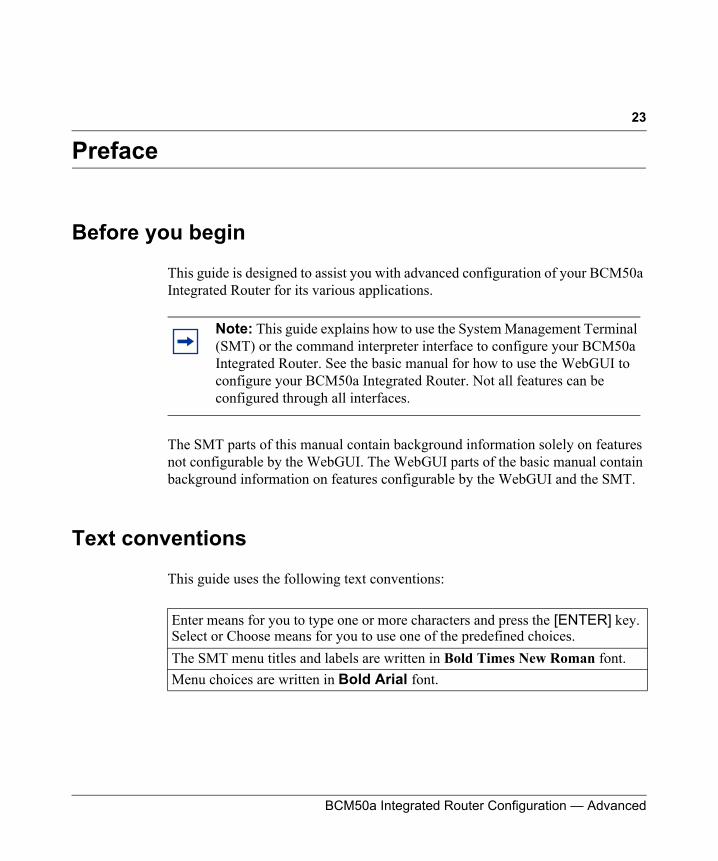
This guide uses the following text conventions:
Note: This guide explains how to use the System Management Terminal (SMT) or the command interpreter interface to configure your BCM50a Integrated Router. See the basic manual for how to use the WebGUI to configure your BCM50a Integrated Router. Not all features can be configured through all interfaces.
Enter means for you to type one or more characters and press the [ENTER] key. Select or Choose means for you to use one of the predefined choices.The SMT menu titles and labels are written in Bold Times New Roman font. Menu choices are written in Bold Arial font.
24 Preface
N0115791
Related publications
For more information about using the BCM50a Integrated Router, refer to the following publications:
• BCM50a Integrated Router Configuration - Basics (N0115790)
The basic manual covers how to use the WebGUI to configure your BCM50a Integrated Router.
• WebGUI Online Help
Embedded WebGUI help for descriptions of individual screens and supplementary information
Hard-copy technical manuals
You can print selected technical manuals and release notes free, directly from the Internet. Go to www.nortel.com/documentation. Find the product for which you need documentation. Then locate the specific category and model or version for your hardware or software product. Use Adobe Reader to open the manuals and release notes, search for the sections you need, and print them on most standard printers. Go to Adobe Systems at www.adobe.com to download a free copy of the Adobe Reader.
How to get help
If you do not see an appropriate number in this list, go to www.nortel.com/cs.
A single keystroke is written in Arial font and enclosed in square brackets, for instance, [ENTER] means the Enter key; [ESC] means the escape key and [SPACE BAR] means the space bar. [UP] and [DOWN] are the up and down arrow keys. Mouse action sequences are denoted using a comma. For example, “click the Apple icon, Control Panels and then Modem” means first click the Apple icon, then point your mouse pointer to Control Panels and then click Modem.

Preface 25
BCM50a Integrated Router Configuration — Advanced
USA and Canada Authorized Distributors
Technical Support - GNTS/GNPS
Telephone:1-800-4NORTEL (1-800-466-7835)
If you already have a PIN Code, you can enter Express Routing Code (ERC) 196#. If you do not yet have a PIN Code, or for general questions and first line support, you can enter ERC 338#.
Web Site:www.nortel.com/cs
Presales Support (CSAN)
Telephone: 1-800-4NORTEL (1-800-466-7835)
Use Express Routing Code (ERC) 1063#
EMEA (Europe, Middle East, Africa)
Technical Support - CTAS
Telephone:*European Free phone 00800 800 89009
European Alternative:
Calls are not free from all countries in Europe, Middle East, or Africa.
Fax: 44-191-555-7980
E-mail:[email protected]
United Kingdom +44 (0)870-907-9009
Africa +27-11-808-4000
Israel 800-945-9779

26 Preface
N0115791
CALA (Caribbean & Latin America)
Technical Support - CTAS
Telephone:1-954-858-7777
E-mail:[email protected]
APAC (Asia Pacific)
Service Business Centre & Pre-Sales Help Desk:+61-2-8870-5511 (Sydney)
Technical Support - GNTS
Telephone:+612 8870 8800
Fax:+612 8870 5569
E-mail:[email protected]
Australia 1-800-NORTEL (1-800-667-835)
China 010-6510-7770India 011-5154-2210
Indonesia 0018-036-1004
Japan 0120-332-533
Malaysia 1800-805-380
New Zealand 0800-449-716
Philippines 1800-1611-0063Singapore 800-616-2004
South Korea 0079-8611-2001
Taiwan 0800-810-500

Preface 27
BCM50a Integrated Router Configuration — Advanced
Thailand 001-800-611-3007
Service Business Centre & Pre-Sales Help Desk
+61-2-8870-5511

28 Preface
N0115791
29
BCM50a Integrated Router Configuration — Advanced
Chapter 1Getting to know your BCM50a Integrated Router
This chapter introduces the main features and applications of the BCM50a Integrated Router.
Introducing the BCM50a Integrated Router
The BCM50a Integrated Router is an ideal secure gateway for all data passing between the Internet and the Local Area Network (LAN).
Your BCM50a Integrated Router integrates high-speed 10/100 Megabits per second (Mb/s) autonegotiating LAN interfaces and a high-speed Asymmetrical Digital Subscriber Line Plus (ADSL2+) port into a single package. The BCM50a Integrated Router is ideal for high-speed Internet browsing and making LAN-to-LAN connections to remote networks. By integrating Digital Subscriber Line (DSL) and Network Address Translation (NAT), the BCM50a Integrated Router provides easy installation and Internet access. By integrating firewall and Virtual Private Network (VPN) capabilities, the BCM50a Integrated Router is a complete security solution that protects your Intranet and efficiently manages data traffic on your network.
Features
This section lists the key features of the BCM50a Integrated Router.
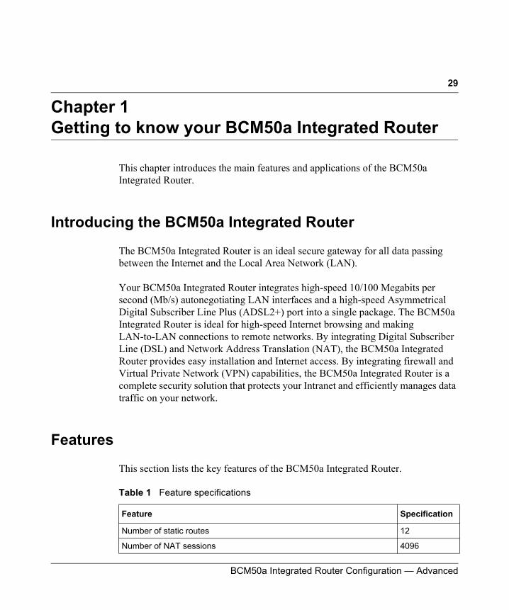
Table 1 Feature specifications
Feature Specification
Number of static routes 12
Number of NAT sessions 4096
30 Chapter 1 Getting to know your BCM50a Integrated Router
N0115791
Physical features
High-speed Internet access
Your BCM50a Integrated Router supports ADSL2+ (Asymmetrical Digital Subscriber Line) for high transmission speeds and long connection distances.
ADSL standards• Multimode standard (ANSI (American National Standards Institute) T1.413,
Issue 2; G.dmt (G.992.1 Discrete Multitone Modulation)• EOC (Embedded Operations Channel) specified in ITU-T
(Telecommunication Standardization Sector of the International Telecommunications Union) G.992.1
• ADSL2 G.dmt.bis (G.992.3)• ADSL2+ (G.992.5)
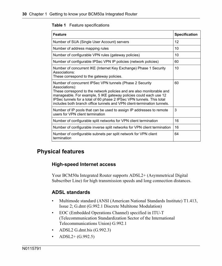
Number of SUA (Single User Account) servers 12
Number of address mapping rules 10
Number of configurable VPN rules (gateway policies) 10
Number of configurable IPSec VPN IP policies (network policies) 60
Number of concurrent IKE (Internet Key Exchange) Phase 1 Security Associations:These correspond to the gateway policies.
10
Number of concurrent IPSec VPN tunnels (Phase 2 Security Associations):These correspond to the network policies and are also monitorable and manageable. For example, 5 IKE gateway policies could each use 12 IPSec tunnels for a total of 60 phase 2 IPSec VPN tunnels. This total includes both branch office tunnels and VPN client-termination tunnels.
60
Number of IP pools that can be used to assign IP addresses to remote users for VPN client termination
3
Number of configurable split networks for VPN client termination 16
Number of configurable inverse split networks for VPN client termination 16
Number of configurable subnets per split network for VPN client termination
64
Table 1 Feature specifications
Feature Specification
Chapter 1 Getting to know your BCM50a Integrated Router 31
BCM50a Integrated Router Configuration — Advanced
• Extended-reach ADSL (ER ADSL)• SRA (Seamless Rate Adaptation)• Autonegotiating rate adaptation• ADSL physical connection ATM (Asynchronous Transfer Mode) AAL5
(Adaptation Layer type 5)·• Multiprotocol over AAL5 (Request For Comments (RFC) 2684/1483)• Support Point-to-Point-Protocol over ATM AAL5 (PPPoA) (RFC 2364)• PPP over Ethernet support for DSL (Digital Subscriber Line) connection
(RFC 2516)• Support Virtual Circuit (VC) based and LLC (Logical Link Control) based
multiplexing• Support OAM (Operational, Administration and Maintenance) VC Hunt• I.610 F4/F5 OAM
Networking compatibility
Your BCM50a Integrated Router is compatible with the major ADSL Digital Subscriber Line Access Multiplexer (DSLAM) providers, making configuration as simple as possible.
Multiplexing
The BCM50a Integrated Router supports VC-based and LLC-based multiplexing.
Encapsulation
The BCM50a Integrated Router supports PPPoA (RFC 2364 - PPP over ATM Adaptation Layer 5), RFC 1483 encapsulation over ATM, MAC (Media Access Control) encapsulated routing (ENET encapsulation) as well as PPP over Ethernet (RFC 2516).
Four-Port switch
A combination of switch and router makes your BCM50a Integrated Router a cost-effective and viable network solution. You can connect up to four computers or phones to the BCM50a Integrated Router without the cost of a switch. Use a switch to add more than four computers or phones to your LAN.
32 Chapter 1 Getting to know your BCM50a Integrated Router
N0115791
Autonegotiating 10/100 Mb/s Ethernet LAN
The LAN interfaces automatically detect if they are on a 10 or a 100 Mb/s Ethernet.
Autosensing 10/100 Mb/s Ethernet LAN
The LAN interfaces automatically adjust to either a crossover or straight through Ethernet cable.
Time and date
Using the BCM50a Integrated Router, you can get the current time and date from an external server when you turn on your BCM50a Integrated Router. You can also set the time manually.
Reset button
There is a 'Cold Reset Router' button that is accessible from the Element Manager Administration/Utilities/Reset page.Use this button to restore the factory default password to setup and the IP address to 192.168.1.1, subnet mask 255.255.255.0, and DHCP server enabled with a pool of 126 IP addresses starting at 192.168.1.2.
Nonphysical features
IPSec VPN capability
Establish Virtual Private Network (VPN) tunnels to connect home or office computers to your company network using data encryption and the Internet; thus providing secure communications without the expense of leased site-to-site lines. VPN is based on the IPSec standard and is fully interoperable with other IPSec-based VPN products.
Nortel Contivity Client Termination
The BCM50a Integrated Router supports VPN connections from computers using Nortel Contivity VPN Client 3.0, 5.01, 5.11, 6.01, 6.02, or 7.01 software.
Chapter 1 Getting to know your BCM50a Integrated Router 33
BCM50a Integrated Router Configuration — Advanced
Certificates
The BCM50a Integrated Router can use certificates (also called digital IDs) to authenticate users. Certificates are based on public-private key pairs. Certificates provide a way to exchange public keys for use in authentication.
SSH
The BCM50a Integrated Router uses the SSH (Secure Shell) secure communication protocol to provide secure encrypted communication between two hosts over an unsecured network.
HTTPS
HyperText Transfer Protocol over Secure Socket Layer, or HTTP over SSL is a web protocol that encrypts and decrypts web sessions. Use HTTPS for secure WebGUI access to the BCM50a Integrated Router.
Firewall
The BCM50a Integrated Router has a stateful inspection firewall with DoS (Denial of Service) protection. By default, when the firewall is activated, all incoming traffic from the WAN (Wide Area Network) to the LAN is blocked unless it is initiated from the LAN. The BCM50a Integrated Router firewall supports TCP/UDP inspection, DoS detection and protection, real time alerts, reports and logs.
Brute force password guessing protection
The BCM50a Integrated Router has a special protection mechanism to discourage brute force password guessing attacks on the BCM50a Integrated Router management interfaces. You can specify a wait time that must expire before you can enter a fourth password after entering three incorrect passwords.
34 Chapter 1 Getting to know your BCM50a Integrated Router
N0115791
Content filtering
The BCM50a Integrated Router can block web features such as ActiveX controls, Java applets, and cookies, as well as disable web proxies. The BCM50a Integrated Router can block specific URLs by using the keyword feature. The administrator can also define time periods and days during which content filtering is enabled.
Packet filtering
The packet filtering mechanism blocks unwanted traffic from entering or leaving your network.
Universal Plug and Play (UPnP)
Using the standard TCP/IP protocol, the BCM50a Integrated Router and other UPnP-enabled devices can dynamically join a network, obtain an IP address, and convey its capabilities to other devices on the network.
Call scheduling
Configure call time periods to restrict and allow access for users on remote nodes.
PPPoE
PPPoE facilitates the interaction of a host with an Internet modem to achieve access to high-speed data networks through a familiar dial-up networking user interface.
Dynamic DNS support
With Dynamic DNS (Domain Name System) support, you can have a static host name alias for a dynamic IP address, so the host is more easily accessible from various locations on the Internet. You must register for this service with a Dynamic DNS service provider.
Chapter 1 Getting to know your BCM50a Integrated Router 35
BCM50a Integrated Router Configuration — Advanced
IP Multicast
The BCM50a Integrated Router can use IP multicast to deliver IP packets to a specific group of hosts. IGMP (Internet Group Management Protocol) is the protocol used to support multicast groups. The BCM50a Integrated Router supports versions 1 and 2.
IP Alias
Using IP Alias, you can partition a physical network into logical networks over the same Ethernet interface. The BCM50a Integrated Router supports three logical LAN interfaces through its single physical Ethernet LAN interface with the BCM50a Integrated Router itself as the gateway for each LAN network.
Central Network Management
With Central Network Management (CNM), an enterprise or service provider network administrator can manage your BCM50a Integrated Router. The enterprise or service provider network administrator can configure your BCM50a Integrated Router, perform firmware upgrades, and do troubleshooting for you.
SNMP
SNMP (Simple Network Management Protocol) is a protocol used for exchanging management information between network devices. SNMP is a member of the TCP/IP protocol suite. Your BCM50a Integrated Router supports SNMP agent functionality, which means that a manager station can manage and monitor the BCM50a Integrated Router through the network. The BCM50a Integrated Router supports SNMP versions 1 and 2 (SNMPv1 and SNMPv2).
Network Address Translation (NAT)
NAT (Network Address Translation — NAT, RFC 1631) translate multiple IP addresses used within one network to different IP addresses known within another network.
36 Chapter 1 Getting to know your BCM50a Integrated Router
N0115791
Traffic Redirect
Traffic Redirect forwards WAN traffic to a backup gateway when the BCM50a Integrated Router cannot connect to the Internet, thus acting as an auxiliary backup when your regular WAN connection fails.
Port Forwarding
Use this feature to forward incoming service requests to a server on your local network. You can enter a single port number or a range of port numbers to be forwarded, and the local IP address of the desired server.
DHCP (Dynamic Host Configuration Protocol)
With DHCP (Dynamic Host Configuration Protocol), individual client computers can obtain the TCP/IP configuration at start-up from a centralized DHCP server. The BCM50a Integrated Router has built in DHCP server capability, enabled by default, which means it can assign IP addresses, an IP default gateway, and DNS servers to all systems that support the DHCP client. The BCM50a Integrated Router can also act as a surrogate DHCP server, where it relays IP address assignment from another DHCP server to the clients.
Full network management
The embedded web configurator is an all platform, web based utility that you can use to easily manage and configure the BCM50a Integrated Router. Most functions of the BCM50a Integrated Router are also software configurable through the SMT (System Management Terminal) interface. The SMT is a menu driven interface that you can access over a Telnet connection.
Logging and tracing
The BCM50a Integrated Router supports the following logging and tracing functions to help with management:
• Built in message logging and packet tracing• Unix syslog facility support
Chapter 1 Getting to know your BCM50a Integrated Router 37
BCM50a Integrated Router Configuration — Advanced
Upgrade BCM50a Integrated Router Firmware
The firmware of the BCM50a Integrated Router can be upgraded manually through the WebGUI.
Embedded FTP and TFTP Servers
The embedded FTP and TFTP servers enable fast firmware upgrades, as well as configuration file backups and restoration.
Applications for the BCM50a Integrated Router
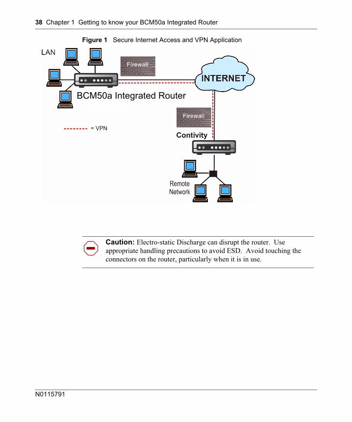
Secure broadband internet access and VPN
The BCM50a Integrated Router provides broadband Internet access through ADSL. The BCM50a Integrated Router also provides IP address sharing and a firewall protected local network with traffic management.
The BCM50a Integrated Router VPN is an ideal, cost effective way to connect branch offices and business partners over the Internet without the need (and expense) of leased lines between sites. The LAN computers can share the VPN tunnels for secure connections to remote computers.
38 Chapter 1 Getting to know your BCM50a Integrated Router
N0115791
Figure 1 Secure Internet Access and VPN Application
Caution: Electro-static Discharge can disrupt the router. Use appropriate handling precautions to avoid ESD. Avoid touching the connectors on the router, particularly when it is in use.
BCM50a Integrated Router
39
BCM50a Integrated Router Configuration — Advanced
Chapter 2Introducing the SMT
This chapter explains how to access the System Management Terminal and gives an overview of its menus.
Introduction to the SMT
The BCM50a Integrated Router SMT (System Management Terminal) is a menu-driven interface that you can access over a Telnet connection. This chapter shows you how to navigate the SMT, and how to configure SMT menus.
Initial screen
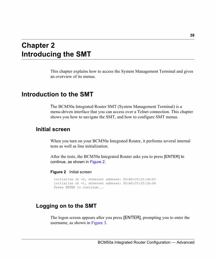
When you turn on your BCM50a Integrated Router, it performs several internal tests as well as line initialization.
After the tests, the BCM50a Integrated Router asks you to press [ENTER] to continue, as shown in Figure 2.
Figure 2 Initial screen
Logging on to the SMT
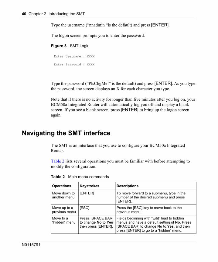
The logon screen appears after you press [ENTER], prompting you to enter the username, as shown in Figure 3.
initialize ch =0, ethernet address: 00:A0:C5:22:1A:03initialize ch =1, ethernet address: 00:A0:C5:22:1A:04Press ENTER to continue...
40 Chapter 2 Introducing the SMT
N0115791
Type the username (“nnadmin “is the default) and press [ENTER].
The logon screen prompts you to enter the password.
Figure 3 SMT Login
Type the password (“PlsChgMe!” is the default) and press [ENTER]. As you type the password, the screen displays an X for each character you type.
Note that if there is no activity for longer than five minutes after you log on, your BCM50a Integrated Router will automatically log you off and display a blank screen. If you see a blank screen, press [ENTER] to bring up the logon screen again.
Navigating the SMT interface
The SMT is an interface that you use to configure your BCM50a Integrated Router.
Table 2 lists several operations you must be familiar with before attempting to modify the configuration.
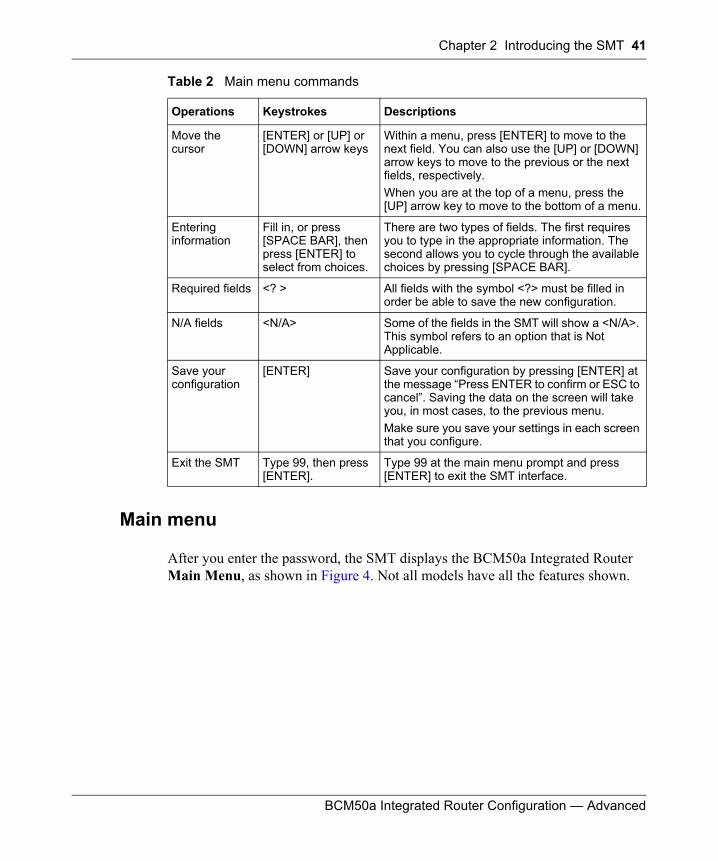
Table 2 Main menu commands
Operations Keystrokes Descriptions
Move down to another menu
[ENTER] To move forward to a submenu, type in the number of the desired submenu and press [ENTER].
Move up to a previous menu
[ESC] Press the [ESC] key to move back to the previous menu.
Move to a “hidden” menu
Press [SPACE BAR] to change No to Yes then press [ENTER].
Fields beginning with “Edit” lead to hidden menus and have a default setting of No. Press [SPACE BAR] to change No to Yes, and then press [ENTER] to go to a “hidden” menu.
Enter Username : XXXX
Enter Password : XXXX
Chapter 2 Introducing the SMT 41
BCM50a Integrated Router Configuration — Advanced
Main menu
After you enter the password, the SMT displays the BCM50a Integrated Router Main Menu, as shown in Figure 4. Not all models have all the features shown.
Move the cursor
[ENTER] or [UP] or [DOWN] arrow keys
Within a menu, press [ENTER] to move to the next field. You can also use the [UP] or [DOWN] arrow keys to move to the previous or the next fields, respectively.When you are at the top of a menu, press the [UP] arrow key to move to the bottom of a menu.
Entering information
Fill in, or press [SPACE BAR], then press [ENTER] to select from choices.
There are two types of fields. The first requires you to type in the appropriate information. The second allows you to cycle through the available choices by pressing [SPACE BAR].
Required fields <? > All fields with the symbol <?> must be filled in order be able to save the new configuration.
N/A fields <N/A> Some of the fields in the SMT will show a <N/A>. This symbol refers to an option that is Not Applicable.
Save your configuration
[ENTER] Save your configuration by pressing [ENTER] at the message “Press ENTER to confirm or ESC to cancel”. Saving the data on the screen will take you, in most cases, to the previous menu.Make sure you save your settings in each screen that you configure.
Exit the SMT Type 99, then press [ENTER].
Type 99 at the main menu prompt and press [ENTER] to exit the SMT interface.
Table 2 Main menu commands
Operations Keystrokes Descriptions
42 Chapter 2 Introducing the SMT
N0115791
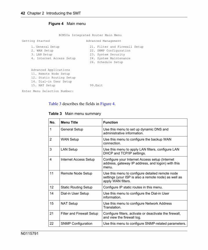
Figure 4 Main menu
Table 3 describes the fields in Figure 4.
BCM50a Integrated Router Main Menu
Getting Started Advanced Management
1. General Setup 2. WAN Setup3. LAN Setup 4. Internet Access Setup
Advanced Applications11. Remote Node Setup 12. Static Routing Setup14. Dial-in User Setup15. NAT Setup
21. Filter and Firewall Setup 22. SNMP Configuration 23. System Security 24. System Maintenance 26. Schedule Setup
99.Exit
Enter Menu Selection Number:
Table 3 Main menu summary
No. Menu Title Function
1 General Setup Use this menu to set up dynamic DNS and administrative information.
2 WAN Setup Use this menu to configure the backup WAN connection.
3 LAN Setup Use this menu to apply LAN filters, configure LAN DHCP and TCP/IP settings.
4 Internet Access Setup Configure your Internet Access setup (Internet address, gateway IP address, and logon) with this menu.
11 Remote Node Setup Use this menu to configure detailed remote node settings (your ISP is also a remote node) as well as apply WAN filters.
12 Static Routing Setup Configure IP static routes in this menu.
14 Dial-in User Setup Use this menu to configure the Dial-in User information.
15 NAT Setup Use this menu to configure Network Address Translation.
21 Filter and Firewall Setup Configure filters, activate or deactivate the firewall, and view the firewall log.
22 SNMP Configuration Use this menu to configure SNMP-related parameters.
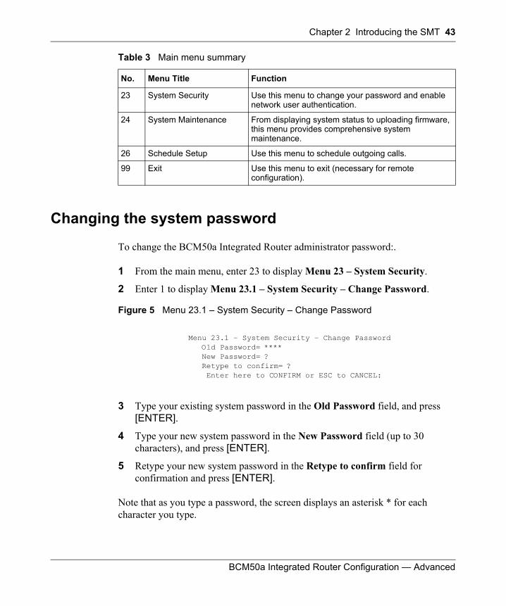
Chapter 2 Introducing the SMT 43
BCM50a Integrated Router Configuration — Advanced
Changing the system password
To change the BCM50a Integrated Router administrator password:.
1 From the main menu, enter 23 to display Menu 23 – System Security.
2 Enter 1 to display Menu 23.1 – System Security – Change Password.
Figure 5 Menu 23.1 – System Security – Change Password
3 Type your existing system password in the Old Password field, and press [ENTER].
4 Type your new system password in the New Password field (up to 30 characters), and press [ENTER].
5 Retype your new system password in the Retype to confirm field for confirmation and press [ENTER].
Note that as you type a password, the screen displays an asterisk * for each character you type.
23 System Security Use this menu to change your password and enable network user authentication.
24 System Maintenance From displaying system status to uploading firmware, this menu provides comprehensive system maintenance.
26 Schedule Setup Use this menu to schedule outgoing calls.
99 Exit Use this menu to exit (necessary for remote configuration).
Menu 23.1 – System Security – Change Password Old Password= **** New Password= ? Retype to confirm= ? Enter here to CONFIRM or ESC to CANCEL:
Table 3 Main menu summary
No. Menu Title Function
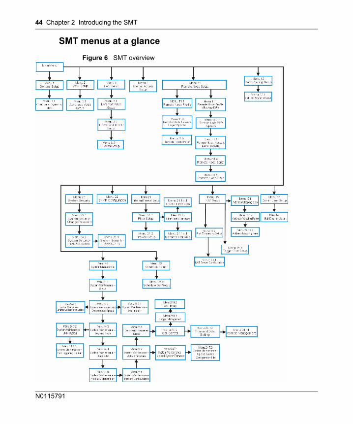
44 Chapter 2 Introducing the SMT
N0115791
SMT menus at a glance
Figure 6 SMT overview
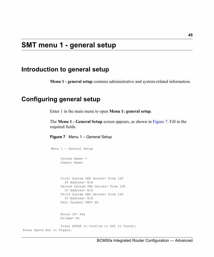
45
BCM50a Integrated Router Configuration — Advanced
SMT menu 1 - general setup
Introduction to general setup
Menu 1 - general setup contains administrative and system-related information.
Configuring general setup
Enter 1 in the main menu to open Menu 1: general setup.
The Menu 1 - General Setup screen appears, as shown in Figure 7. Fill in the required fields.
Figure 7 Menu 1 – General Setup
Menu 1 - General Setup
System Name= ? Domain Name=
First System DNS Server= From ISP IP Address= N/A Second System DNS Server= From ISP IP Address= N/A Third System DNS Server= From ISP IP Address= N/A Edit Dynamic DNS= No
Route IP= Yes Bridge= No
Press ENTER to Confirm or ESC to Cancel:Press Space Bar to Toggle.
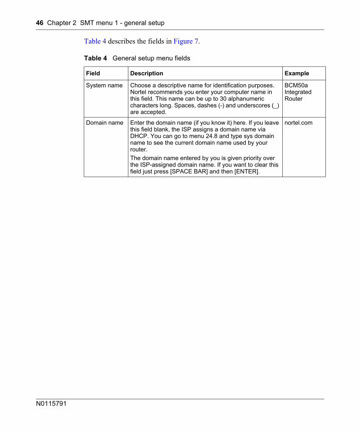
46 Chapter 2 SMT menu 1 - general setup
N0115791
Table 4 describes the fields in Figure 7.
Table 4 General setup menu fields
Field Description Example
System name Choose a descriptive name for identification purposes. Nortel recommends you enter your computer name in this field. This name can be up to 30 alphanumeric characters long. Spaces, dashes (-) and underscores (_) are accepted.
BCM50a Integrated Router
Domain name Enter the domain name (if you know it) here. If you leave this field blank, the ISP assigns a domain name via DHCP. You can go to menu 24.8 and type sys domain name to see the current domain name used by your router.The domain name entered by you is given priority over the ISP-assigned domain name. If you want to clear this field just press [SPACE BAR] and then [ENTER].
nortel.com
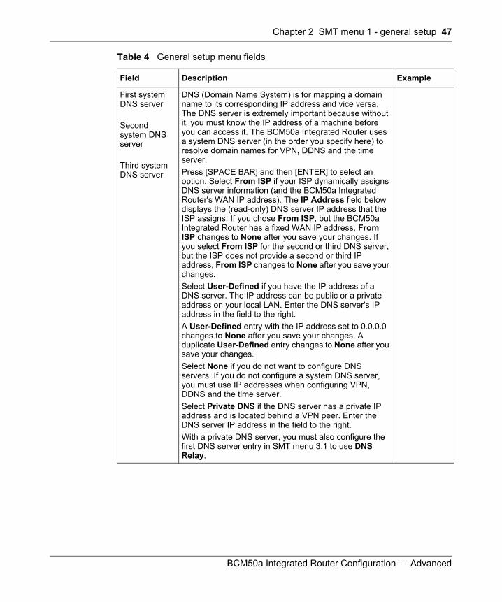
Chapter 2 SMT menu 1 - general setup 47
BCM50a Integrated Router Configuration — Advanced
First system DNS server Second system DNS server
Third system DNS server
DNS (Domain Name System) is for mapping a domain name to its corresponding IP address and vice versa. The DNS server is extremely important because without it, you must know the IP address of a machine before you can access it. The BCM50a Integrated Router uses a system DNS server (in the order you specify here) to resolve domain names for VPN, DDNS and the time server.Press [SPACE BAR] and then [ENTER] to select an option. Select From ISP if your ISP dynamically assigns DNS server information (and the BCM50a Integrated Router's WAN IP address). The IP Address field below displays the (read-only) DNS server IP address that the ISP assigns. If you chose From ISP, but the BCM50a Integrated Router has a fixed WAN IP address, From ISP changes to None after you save your changes. If you select From ISP for the second or third DNS server, but the ISP does not provide a second or third IP address, From ISP changes to None after you save your changes.Select User-Defined if you have the IP address of a DNS server. The IP address can be public or a private address on your local LAN. Enter the DNS server's IP address in the field to the right. A User-Defined entry with the IP address set to 0.0.0.0 changes to None after you save your changes. A duplicate User-Defined entry changes to None after you save your changes.Select None if you do not want to configure DNS servers. If you do not configure a system DNS server, you must use IP addresses when configuring VPN, DDNS and the time server.Select Private DNS if the DNS server has a private IP address and is located behind a VPN peer. Enter the DNS server IP address in the field to the right. With a private DNS server, you must also configure the first DNS server entry in SMT menu 3.1 to use DNS Relay.
Table 4 General setup menu fields
Field Description Example
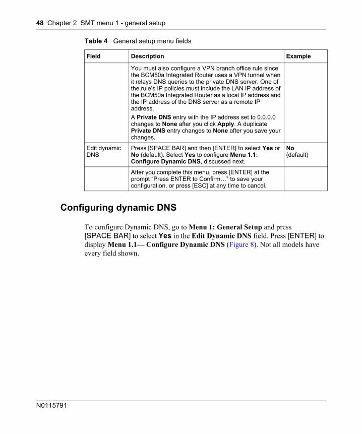
48 Chapter 2 SMT menu 1 - general setup
N0115791
Configuring dynamic DNS
To configure Dynamic DNS, go to Menu 1: General Setup and press [SPACE BAR] to select Yes in the Edit Dynamic DNS field. Press [ENTER] to display Menu 1.1— Configure Dynamic DNS (Figure 8). Not all models have every field shown.
You must also configure a VPN branch office rule since the BCM50a Integrated Router uses a VPN tunnel when it relays DNS queries to the private DNS server. One of the rule’s IP policies must include the LAN IP address of the BCM50a Integrated Router as a local IP address and the IP address of the DNS server as a remote IP address. A Private DNS entry with the IP address set to 0.0.0.0 changes to None after you click Apply. A duplicate Private DNS entry changes to None after you save your changes.
Edit dynamic DNS
Press [SPACE BAR] and then [ENTER] to select Yes or No (default). Select Yes to configure Menu 1.1: Configure Dynamic DNS, discussed next.
No(default)
After you complete this menu, press [ENTER] at the prompt “Press ENTER to Confirm…” to save your configuration, or press [ESC] at any time to cancel.
Table 4 General setup menu fields
Field Description Example
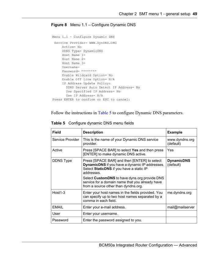
Chapter 2 SMT menu 1 - general setup 49
BCM50a Integrated Router Configuration — Advanced
Figure 8 Menu 1.1 – Configure Dynamic DNS
Follow the instructions in Table 5 to configure Dynamic DNS parameters.
Menu 1.1 - Configure Dynamic DNS
Service Provider= WWW.DynDNS.ORG Active= No DDNS Type= DynamicDNS Host Name 1= Host Name 2= Host Name 3= Username= Password= ******** Enable Wildcard Option= No Enable Off Line Option= N/A IP Address Update Policy: DDNS Server Auto Detect IP Address= No Use Specified IP Address= No Use IP Address= N/APress ENTER to confirm or ESC to cancel:
Table 5 Configure dynamic DNS menu fields
Field Description Example
Service Provider This is the name of your Dynamic DNS service provider.
www.dyndns.org(default)
Active Press [SPACE BAR] to select Yes and then press [ENTER] to make dynamic DNS active.
Yes
DDNS Type Press [SPACE BAR] and then [ENTER] to select DynamicDNS if you have a dynamic IP addresses. Select StaticDNS if you have a static IP addresses.Select CustomDNS to have dyns.org provide DNS service for a domain name that you already have from a source other than dyndns.org.
DynamicDNS(default)
Host1-3 Enter your host names in the fields provided. You can specify up to two host names separated by a comma in each field.
me.dyndns.org
EMAIL Enter your e-mail address. mail@mailserver
User Enter your username.
Password Enter the password assigned to you.
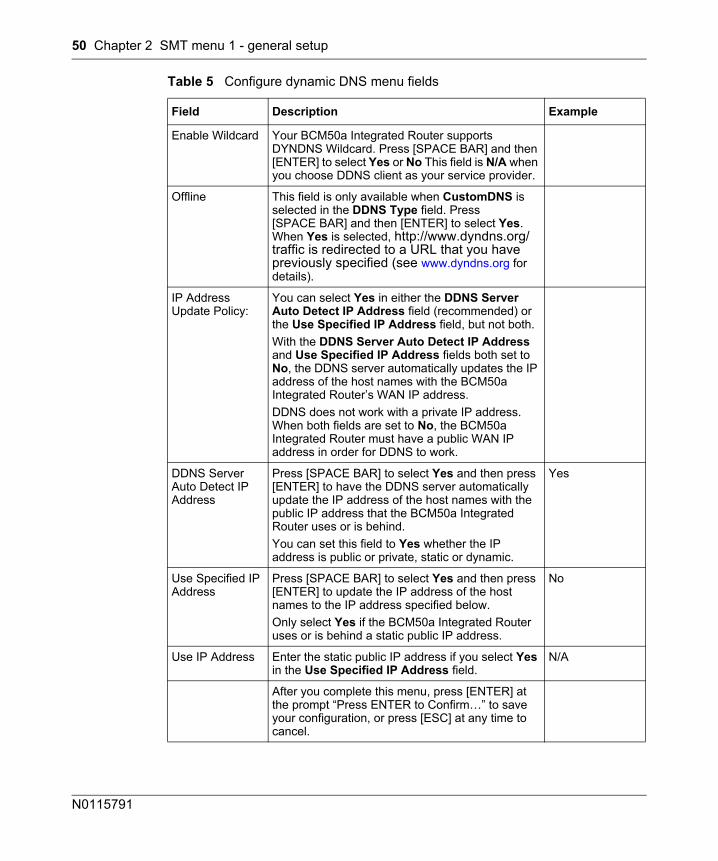
50 Chapter 2 SMT menu 1 - general setup
N0115791
Enable Wildcard Your BCM50a Integrated Router supports DYNDNS Wildcard. Press [SPACE BAR] and then [ENTER] to select Yes or No This field is N/A when you choose DDNS client as your service provider.
Offline This field is only available when CustomDNS is selected in the DDNS Type field. Press [SPACE BAR] and then [ENTER] to select Yes. When Yes is selected, http://www.dyndns.org/ traffic is redirected to a URL that you have previously specified (see www.dyndns.org for details).
IP Address Update Policy:
You can select Yes in either the DDNS Server Auto Detect IP Address field (recommended) or the Use Specified IP Address field, but not both.With the DDNS Server Auto Detect IP Address and Use Specified IP Address fields both set to No, the DDNS server automatically updates the IP address of the host names with the BCM50a Integrated Router’s WAN IP address. DDNS does not work with a private IP address. When both fields are set to No, the BCM50a Integrated Router must have a public WAN IP address in order for DDNS to work.
DDNS Server Auto Detect IP Address
Press [SPACE BAR] to select Yes and then press [ENTER] to have the DDNS server automatically update the IP address of the host names with the public IP address that the BCM50a Integrated Router uses or is behind. You can set this field to Yes whether the IP address is public or private, static or dynamic.
Yes
Use Specified IP Address
Press [SPACE BAR] to select Yes and then press [ENTER] to update the IP address of the host names to the IP address specified below. Only select Yes if the BCM50a Integrated Router uses or is behind a static public IP address.
No
Use IP Address Enter the static public IP address if you select Yes in the Use Specified IP Address field.
N/A
After you complete this menu, press [ENTER] at the prompt “Press ENTER to Confirm…” to save your configuration, or press [ESC] at any time to cancel.
Table 5 Configure dynamic DNS menu fields
Field Description Example

Chapter 2 SMT menu 1 - general setup 51
BCM50a Integrated Router Configuration — Advanced
The IP address updates when you reconfigure menu 1 or perform DHCP client renewal.

52 Chapter 2 SMT menu 1 - general setup
N0115791
53
BCM50a Integrated Router Configuration — Advanced
Chapter 3WAN Setup
This chapter describes how to configure the WAN using Menu 2.
Introduction to WAN setup
This chapter explains how to configure the settings for your WAN port.
WAN setup
From the main menu, enter 2 to open Menu 2.
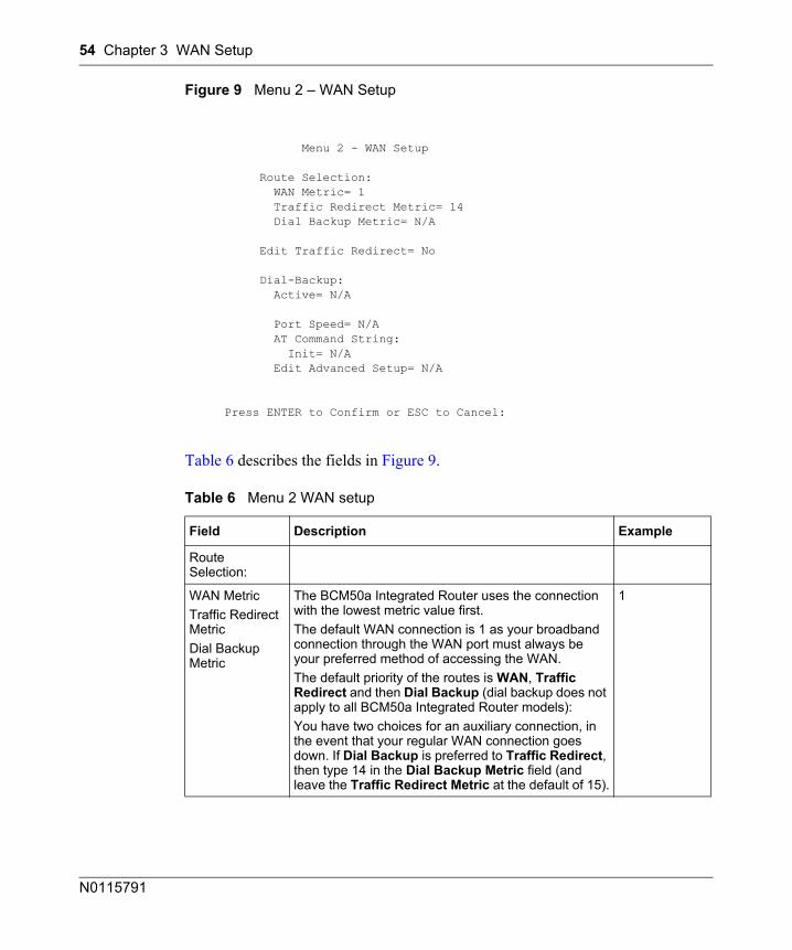
54 Chapter 3 WAN Setup
N0115791
Figure 9 Menu 2 – WAN Setup
Table 6 describes the fields in Figure 9.
Menu 2 - WAN Setup
Route Selection: WAN Metric= 1 Traffic Redirect Metric= 14 Dial Backup Metric= N/A
Edit Traffic Redirect= No
Dial-Backup: Active= N/A
Port Speed= N/A AT Command String: Init= N/A Edit Advanced Setup= N/A
Press ENTER to Confirm or ESC to Cancel:
Table 6 Menu 2 WAN setup
Field Description Example
Route Selection:
WAN MetricTraffic Redirect MetricDial Backup Metric
The BCM50a Integrated Router uses the connection with the lowest metric value first.The default WAN connection is 1 as your broadband connection through the WAN port must always be your preferred method of accessing the WAN.The default priority of the routes is WAN, Traffic Redirect and then Dial Backup (dial backup does not apply to all BCM50a Integrated Router models): You have two choices for an auxiliary connection, in the event that your regular WAN connection goes down. If Dial Backup is preferred to Traffic Redirect, then type 14 in the Dial Backup Metric field (and leave the Traffic Redirect Metric at the default of 15).
1
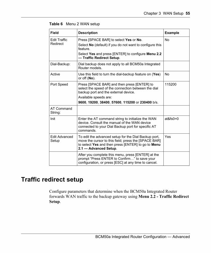
Chapter 3 WAN Setup 55
BCM50a Integrated Router Configuration — Advanced
Traffic redirect setup
Configure parameters that determine when the BCM50a Integrated Router forwards WAN traffic to the backup gateway using Menu 2.2 - Traffic Redirect Setup.
Edit Traffic Redirect
Press [SPACE BAR] to select Yes or No. Select No (default) if you do not want to configure this feature. Select Yes and press [ENTER] to configure Menu 2.2 — Traffic Redirect Setup.
No
Dial-Backup: Dial backup does not apply to all BCM50a Integrated Router models.
Active Use this field to turn the dial-backup feature on (Yes) or off (No).
No
Port Speed Press [SPACE BAR] and then press [ENTER] to select the speed of the connection between the dial backup port and the external device.Available speeds are:9600, 19200, 38400, 57600, 115200 or 230400 b/s.
115200
AT Command String:
Init Enter the AT command string to initialize the WAN device. Consult the manual of the WAN device connected to your Dial Backup port for specific AT commands.
at&fs0=0
Edit Advanced Setup
To edit the advanced setup for the Dial Backup port, move the cursor to this field; press the [SPACE BAR] to select Yes and then press [ENTER] to go to Menu 2.1 — Advanced Setup.
Yes
After you complete this menu, press [ENTER] at the prompt “Press ENTER to Confirm…” to save your configuration, or press [ESC] at any time to cancel.
Table 6 Menu 2 WAN setup
Field Description Example
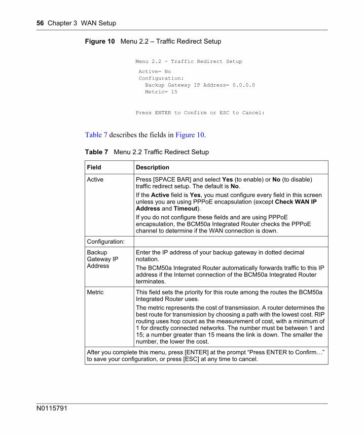
56 Chapter 3 WAN Setup
N0115791
Figure 10 Menu 2.2 – Traffic Redirect Setup
Table 7 describes the fields in Figure 10.
Menu 2.2 - Traffic Redirect Setup
Active= No Configuration: Backup Gateway IP Address= 0.0.0.0 Metric= 15
Press ENTER to Confirm or ESC to Cancel:
Table 7 Menu 2.2 Traffic Redirect Setup
Field Description
Active Press [SPACE BAR] and select Yes (to enable) or No (to disable) traffic redirect setup. The default is No.If the Active field is Yes, you must configure every field in this screen unless you are using PPPoE encapsulation (except Check WAN IP Address and Timeout). If you do not configure these fields and are using PPPoE encapsulation, the BCM50a Integrated Router checks the PPPoE channel to determine if the WAN connection is down.
Configuration:
Backup Gateway IP Address
Enter the IP address of your backup gateway in dotted decimal notation.The BCM50a Integrated Router automatically forwards traffic to this IP address if the Internet connection of the BCM50a Integrated Router terminates.
Metric This field sets the priority for this route among the routes the BCM50a Integrated Router uses. The metric represents the cost of transmission. A router determines the best route for transmission by choosing a path with the lowest cost. RIP routing uses hop count as the measurement of cost, with a minimum of 1 for directly connected networks. The number must be between 1 and 15; a number greater than 15 means the link is down. The smaller the number, the lower the cost.
After you complete this menu, press [ENTER] at the prompt “Press ENTER to Confirm…” to save your configuration, or press [ESC] at any time to cancel.
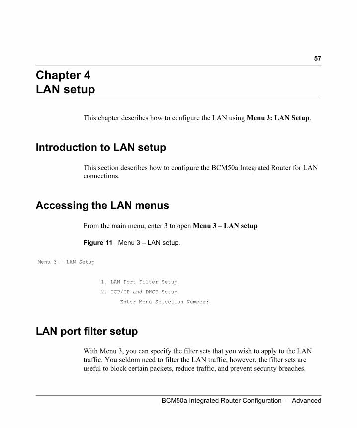
57
BCM50a Integrated Router Configuration — Advanced
Chapter 4LAN setup
This chapter describes how to configure the LAN using Menu 3: LAN Setup.
Introduction to LAN setup
This section describes how to configure the BCM50a Integrated Router for LAN connections.
Accessing the LAN menus
From the main menu, enter 3 to open Menu 3 – LAN setup
Figure 11 Menu 3 – LAN setup.
LAN port filter setup
With Menu 3, you can specify the filter sets that you wish to apply to the LAN traffic. You seldom need to filter the LAN traffic, however, the filter sets are useful to block certain packets, reduce traffic, and prevent security breaches.
Menu 3 - LAN Setup
1. LAN Port Filter Setup
2. TCP/IP and DHCP Setup
Enter Menu Selection Number:
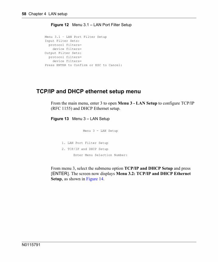
58 Chapter 4 LAN setup
N0115791
Figure 12 Menu 3.1 – LAN Port Filter Setup
TCP/IP and DHCP ethernet setup menu
From the main menu, enter 3 to open Menu 3 - LAN Setup to configure TCP/IP (RFC 1155) and DHCP Ethernet setup.
Figure 13 Menu 3 – LAN Setup
From menu 3, select the submenu option TCP/IP and DHCP Setup and press [ENTER]. The screen now displays Menu 3.2: TCP/IP and DHCP Ethernet Setup, as shown in Figure 14.
Menu 3.1 – LAN Port Filter SetupInput Filter Sets: protocol filters= device filters=Output Filter Sets: protocol filters= device filters=Press ENTER to Confirm or ESC to Cancel:
Menu 3 - LAN Setup
1. LAN Port Filter Setup
2. TCP/IP and DHCP Setup
Enter Menu Selection Number:
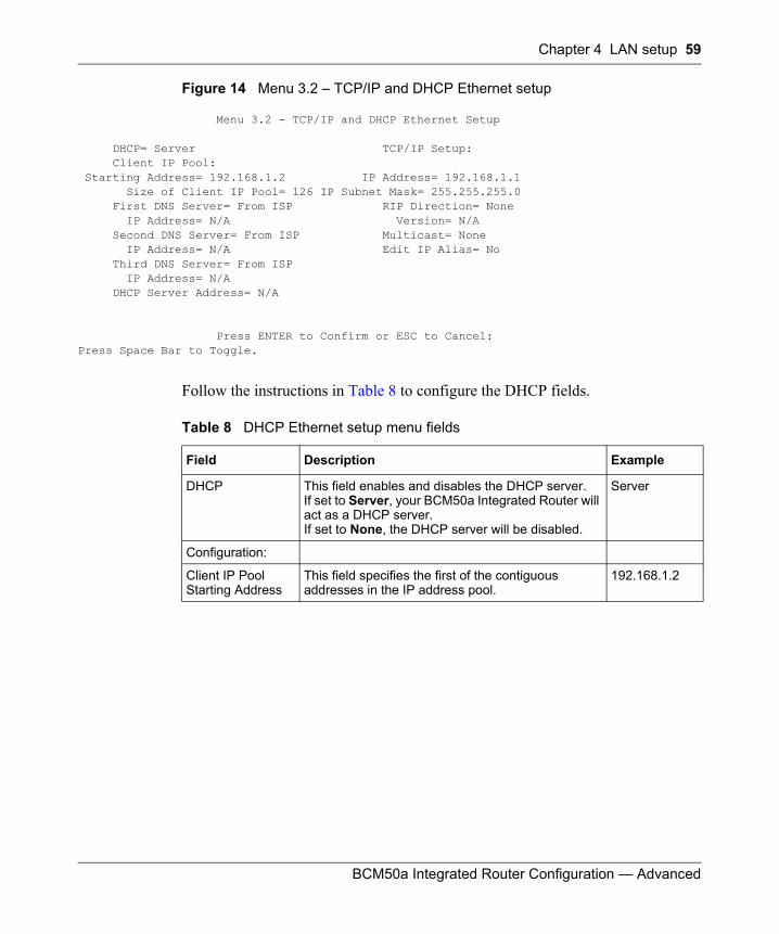
Chapter 4 LAN setup 59
BCM50a Integrated Router Configuration — Advanced
Figure 14 Menu 3.2 – TCP/IP and DHCP Ethernet setup
Menu 3.2 - TCP/IP and DHCP Ethernet Setup
DHCP= Server TCP/IP Setup: Client IP Pool: Starting Address= 192.168.1.2 IP Address= 192.168.1.1 Size of Client IP Pool= 126 IP Subnet Mask= 255.255.255.0 First DNS Server= From ISP RIP Direction= None IP Address= N/A Version= N/A Second DNS Server= From ISP Multicast= None IP Address= N/A Edit IP Alias= No Third DNS Server= From ISP IP Address= N/A DHCP Server Address= N/A
Press ENTER to Confirm or ESC to Cancel:Press Space Bar to Toggle.
Follow the instructions in Table 8 to configure the DHCP fields.
Table 8 DHCP Ethernet setup menu fields
Field Description Example
DHCP This field enables and disables the DHCP server.If set to Server, your BCM50a Integrated Router will act as a DHCP server.If set to None, the DHCP server will be disabled.
Server
Configuration:
Client IP Pool Starting Address
This field specifies the first of the contiguous addresses in the IP address pool.
192.168.1.2
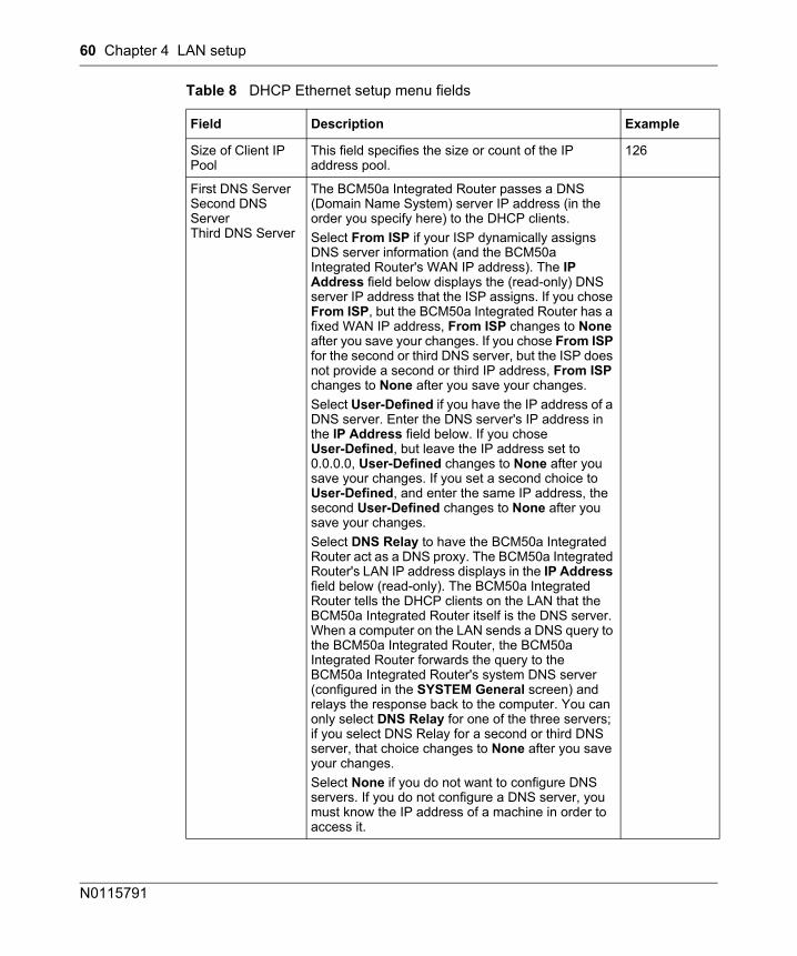
60 Chapter 4 LAN setup
N0115791
Size of Client IP Pool
This field specifies the size or count of the IP address pool.
126
First DNS Server Second DNS Server Third DNS Server
The BCM50a Integrated Router passes a DNS (Domain Name System) server IP address (in the order you specify here) to the DHCP clients. Select From ISP if your ISP dynamically assigns DNS server information (and the BCM50a Integrated Router's WAN IP address). The IP Address field below displays the (read-only) DNS server IP address that the ISP assigns. If you chose From ISP, but the BCM50a Integrated Router has a fixed WAN IP address, From ISP changes to None after you save your changes. If you chose From ISP for the second or third DNS server, but the ISP does not provide a second or third IP address, From ISP changes to None after you save your changes. Select User-Defined if you have the IP address of a DNS server. Enter the DNS server's IP address in the IP Address field below. If you chose User-Defined, but leave the IP address set to 0.0.0.0, User-Defined changes to None after you save your changes. If you set a second choice to User-Defined, and enter the same IP address, the second User-Defined changes to None after you save your changes.Select DNS Relay to have the BCM50a Integrated Router act as a DNS proxy. The BCM50a Integrated Router's LAN IP address displays in the IP Address field below (read-only). The BCM50a Integrated Router tells the DHCP clients on the LAN that the BCM50a Integrated Router itself is the DNS server. When a computer on the LAN sends a DNS query to the BCM50a Integrated Router, the BCM50a Integrated Router forwards the query to the BCM50a Integrated Router's system DNS server (configured in the SYSTEM General screen) and relays the response back to the computer. You can only select DNS Relay for one of the three servers; if you select DNS Relay for a second or third DNS server, that choice changes to None after you save your changes.Select None if you do not want to configure DNS servers. If you do not configure a DNS server, you must know the IP address of a machine in order to access it.
Table 8 DHCP Ethernet setup menu fields
Field Description Example
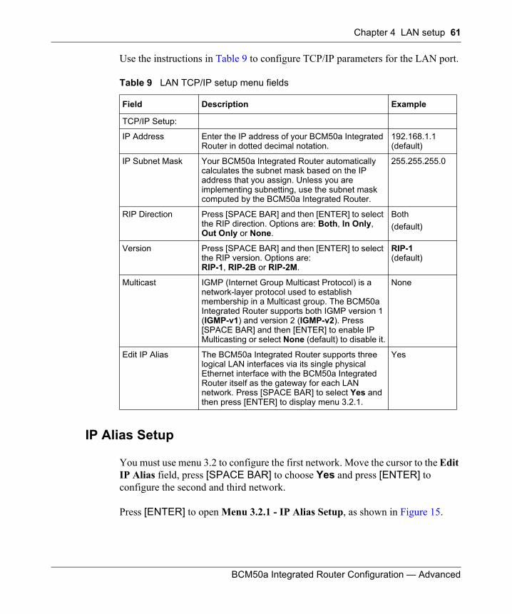
Chapter 4 LAN setup 61
BCM50a Integrated Router Configuration — Advanced
Use the instructions in Table 9 to configure TCP/IP parameters for the LAN port.
IP Alias Setup
You must use menu 3.2 to configure the first network. Move the cursor to the Edit IP Alias field, press [SPACE BAR] to choose Yes and press [ENTER] to configure the second and third network.
Press [ENTER] to open Menu 3.2.1 - IP Alias Setup, as shown in Figure 15.
Table 9 LAN TCP/IP setup menu fields
Field Description Example
TCP/IP Setup:
IP Address Enter the IP address of your BCM50a Integrated Router in dotted decimal notation.
192.168.1.1 (default)
IP Subnet Mask Your BCM50a Integrated Router automatically calculates the subnet mask based on the IP address that you assign. Unless you are implementing subnetting, use the subnet mask computed by the BCM50a Integrated Router.
255.255.255.0
RIP Direction Press [SPACE BAR] and then [ENTER] to select the RIP direction. Options are: Both, In Only, Out Only or None.
Both(default)
Version Press [SPACE BAR] and then [ENTER] to select the RIP version. Options are: RIP-1, RIP-2B or RIP-2M.
RIP-1(default)
Multicast IGMP (Internet Group Multicast Protocol) is a network-layer protocol used to establish membership in a Multicast group. The BCM50a Integrated Router supports both IGMP version 1 (IGMP-v1) and version 2 (IGMP-v2). Press [SPACE BAR] and then [ENTER] to enable IP Multicasting or select None (default) to disable it.
None
Edit IP Alias The BCM50a Integrated Router supports three logical LAN interfaces via its single physical Ethernet interface with the BCM50a Integrated Router itself as the gateway for each LAN network. Press [SPACE BAR] to select Yes and then press [ENTER] to display menu 3.2.1.
Yes
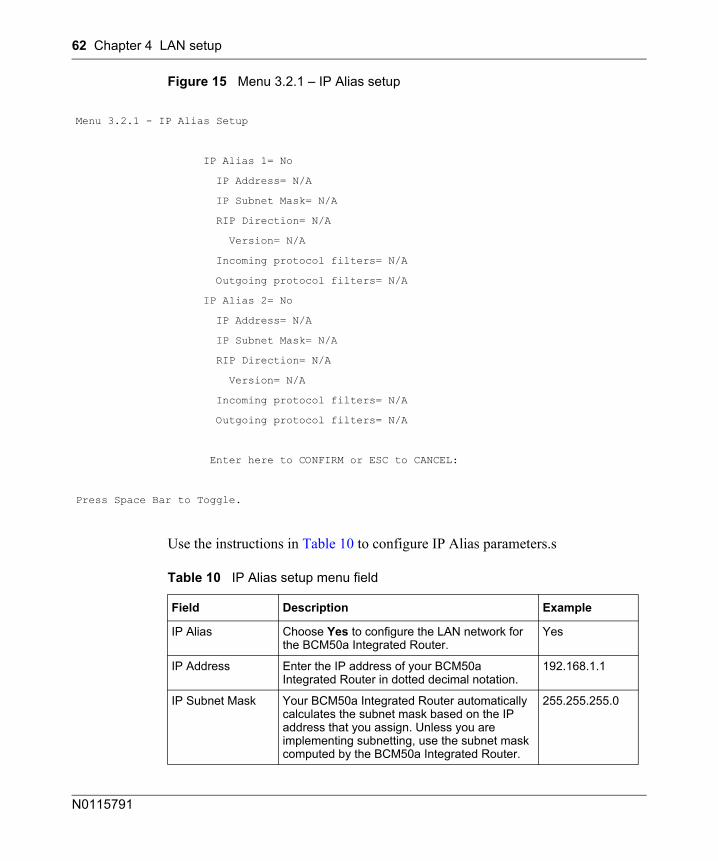
62 Chapter 4 LAN setup
N0115791
Figure 15 Menu 3.2.1 – IP Alias setup
Use the instructions in Table 10 to configure IP Alias parameters.s
Menu 3.2.1 - IP Alias Setup
IP Alias 1= No
IP Address= N/A
IP Subnet Mask= N/A
RIP Direction= N/A
Version= N/A
Incoming protocol filters= N/A
Outgoing protocol filters= N/A
IP Alias 2= No
IP Address= N/A
IP Subnet Mask= N/A
RIP Direction= N/A
Version= N/A
Incoming protocol filters= N/A
Outgoing protocol filters= N/A
Enter here to CONFIRM or ESC to CANCEL:
Press Space Bar to Toggle.
Table 10 IP Alias setup menu field
Field Description Example
IP Alias Choose Yes to configure the LAN network for the BCM50a Integrated Router.
Yes
IP Address Enter the IP address of your BCM50a Integrated Router in dotted decimal notation.
192.168.1.1
IP Subnet Mask Your BCM50a Integrated Router automatically calculates the subnet mask based on the IP address that you assign. Unless you are implementing subnetting, use the subnet mask computed by the BCM50a Integrated Router.
255.255.255.0
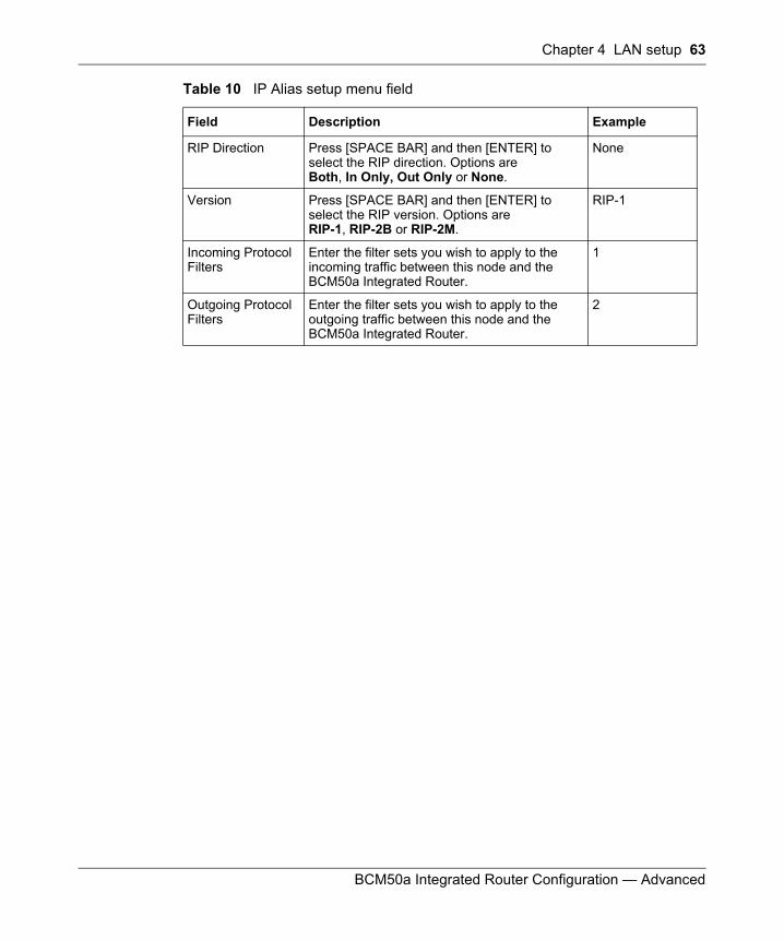
Chapter 4 LAN setup 63
BCM50a Integrated Router Configuration — Advanced
RIP Direction Press [SPACE BAR] and then [ENTER] to select the RIP direction. Options areBoth, In Only, Out Only or None.
None
Version Press [SPACE BAR] and then [ENTER] to select the RIP version. Options areRIP-1, RIP-2B or RIP-2M.
RIP-1
Incoming Protocol Filters
Enter the filter sets you wish to apply to the incoming traffic between this node and the BCM50a Integrated Router.
1
Outgoing Protocol Filters
Enter the filter sets you wish to apply to the outgoing traffic between this node and the BCM50a Integrated Router.
2
Table 10 IP Alias setup menu field
Field Description Example

64 Chapter 4 LAN setup
N0115791
65
BCM50a Integrated Router Configuration — Advanced
Chapter 5Internet access
This chapter shows you how to configure your BCM50a Integrated Router for Internet access.
Internet access configuration
Using Menu 4 you can enter the Internet Access information in one screen. Menu 4 is actually a simplified setup for one of the remote nodes that you can access in Menu 11. Before you configure your BCM50a Integrated Router for Internet access, you must collect your Internet account information.
Use your Internet account information from your ISP to fill in this menu. Note that if you are using PPPoA or PPPoE encapsulation, the only ISP information you need is a logon name and password. You only need to know the Ethernet Encapsulation Gateway IP address if you are using ENET ENCAP encapsulation.
From the main menu, type 4 to display Menu 4 — Internet Access Setup, as shown in the following figure.
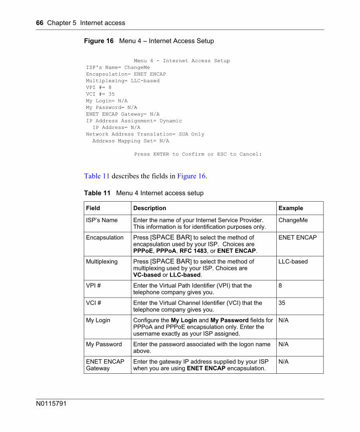
66 Chapter 5 Internet access
N0115791
Figure 16 Menu 4 – Internet Access Setup
Table 11 describes the fields in Figure 16.
Menu 4 - Internet Access SetupISP's Name= ChangeMeEncapsulation= ENET ENCAPMultiplexing= LLC-basedVPI #= 8VCI #= 35My Login= N/AMy Password= N/AENET ENCAP Gateway= N/AIP Address Assignment= Dynamic IP Address= N/ANetwork Address Translation= SUA Only Address Mapping Set= N/A
Press ENTER to Confirm or ESC to Cancel:
Table 11 Menu 4 Internet access setup
Field Description Example
ISP’s Name Enter the name of your Internet Service Provider. This information is for identification purposes only.
ChangeMe
Encapsulation Press [SPACE BAR] to select the method of encapsulation used by your ISP. Choices are PPPoE, PPPoA, RFC 1483, or ENET ENCAP.
ENET ENCAP
Multiplexing Press [SPACE BAR] to select the method of multiplexing used by your ISP. Choices are VC-based or LLC-based.
LLC-based
VPI # Enter the Virtual Path Identifier (VPI) that the telephone company gives you.
8
VCI # Enter the Virtual Channel Identifier (VCI) that the telephone company gives you.
35
My Login Configure the My Login and My Password fields for PPPoA and PPPoE encapsulation only. Enter the username exactly as your ISP assigned.
N/A
My Password Enter the password associated with the logon name above.
N/A
ENET ENCAP Gateway
Enter the gateway IP address supplied by your ISP when you are using ENET ENCAP encapsulation.
N/A
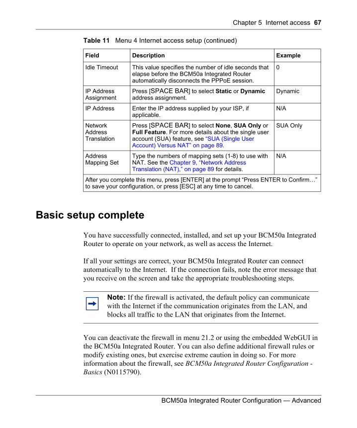
Chapter 5 Internet access 67
BCM50a Integrated Router Configuration — Advanced
Basic setup complete
You have successfully connected, installed, and set up your BCM50a Integrated Router to operate on your network, as well as access the Internet.
If all your settings are correct, your BCM50a Integrated Router can connect automatically to the Internet. If the connection fails, note the error message that you receive on the screen and take the appropriate troubleshooting steps.
You can deactivate the firewall in menu 21.2 or using the embedded WebGUI in the BCM50a Integrated Router. You can also define additional firewall rules or modify existing ones, but exercise extreme caution in doing so. For more information about the firewall, see BCM50a Integrated Router Configuration - Basics (N0115790).
Idle Timeout This value specifies the number of idle seconds that elapse before the BCM50a Integrated Router automatically disconnects the PPPoE session.
0
IP Address Assignment
Press [SPACE BAR] to select Static or Dynamic address assignment.
Dynamic
IP Address Enter the IP address supplied by your ISP, if applicable.
N/A
Network Address Translation
Press [SPACE BAR] to select None, SUA Only or Full Feature. For more details about the single user account (SUA) feature, see “SUA (Single User Account) Versus NAT” on page 89.
SUA Only
Address Mapping Set
Type the numbers of mapping sets (1-8) to use with NAT. See the Chapter 9, “Network Address Translation (NAT),” on page 89 for details.
N/A
After you complete this menu, press [ENTER] at the prompt “Press ENTER to Confirm…” to save your configuration, or press [ESC] at any time to cancel.
Note: If the firewall is activated, the default policy can communicate with the Internet if the communication originates from the LAN, and blocks all traffic to the LAN that originates from the Internet.
Table 11 Menu 4 Internet access setup (continued)
Field Description Example

68 Chapter 5 Internet access
N0115791
69
BCM50a Integrated Router Configuration — Advanced
Chapter 6Remote Node setup
This chapter shows you how to configure a remote node.
Introduction to Remote Node setup
This section describes the protocol-independent parameters for a remote node. A remote node is required for placing calls to a remote gateway. A remote node represents both the remote gateway and the network behind it across a WAN connection. When you use menu 4 to set up Internet access, you are configuring one of the remote nodes.
You first choose a remote node in Menu 11- Remote Node Setup. You can then edit that node’s profile in menu 11.1, as well as configure specific settings in three submenus: edit IP and bridge options in menu 11.3; edit ATM options in menu 11.6; and edit filter sets in menu 11.5.
Outgoing Authentication Protocol
Generally speaking, you should employ the strongest authentication protocol possible, for obvious reasons. However, some vendor’s implementation includes a specific authentication protocol in the user profile. It will disconnect if the negotiated protocol is different from that in the user profile, even when the negotiated protocol is stronger than specified. If you encounter a case where the peer disconnects right after a successful authentication, please make sure that you specify the correct authentication protocol when connecting to such an implementation.
70 Chapter 6 Remote Node setup
N0115791
Nailed-Up Connection
A nailed-up connection is a dial-up line where the connection is always up regardless of traffic demand. The BCM50a Integrated Router does two things when you specify a nailed-up connection. The first is that idle timeout is disabled. The second is that the BCM50a Integrated Router will try to bring up the connection when turned on and whenever the connection is down. A nailed-up connection can be very expensive for obvious reasons.
Do not specify a nailed-up connection unless your telephone company offers flat-rate service or you need a constant connection and the cost is of no concern.
The following table describes the fields specific to PPPoE encapsulation.
Remote Node setup
This section describes the protocol-independent parameters for a remote node.
Remote Node profile
To configure a remote node, follow these steps:
1 From the main menu, enter 11 to display Menu 11 - Remote Node Setup.
2 When menu 11 appears, as shown in the following figure, type the number of the remote node that you want to configure.
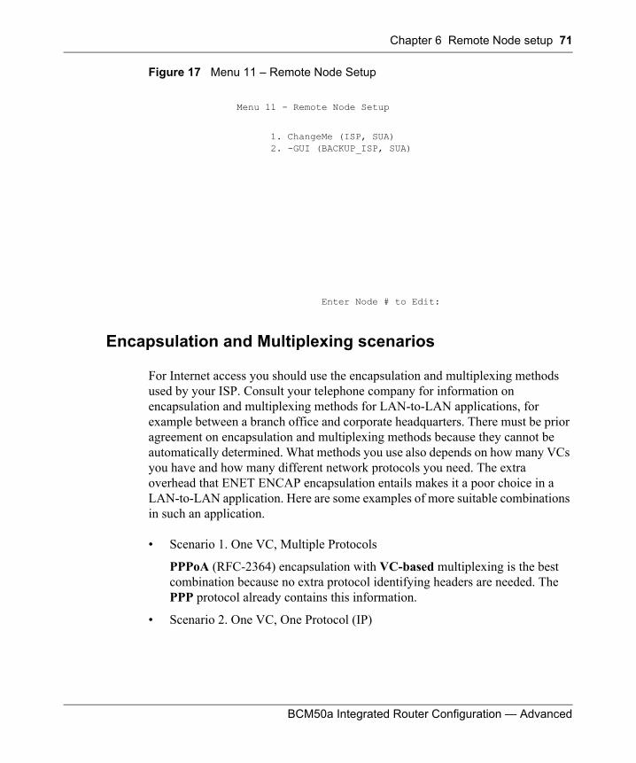
Chapter 6 Remote Node setup 71
BCM50a Integrated Router Configuration — Advanced
Figure 17 Menu 11 – Remote Node Setup
Encapsulation and Multiplexing scenarios
For Internet access you should use the encapsulation and multiplexing methods used by your ISP. Consult your telephone company for information on encapsulation and multiplexing methods for LAN-to-LAN applications, for example between a branch office and corporate headquarters. There must be prior agreement on encapsulation and multiplexing methods because they cannot be automatically determined. What methods you use also depends on how many VCs you have and how many different network protocols you need. The extra overhead that ENET ENCAP encapsulation entails makes it a poor choice in a LAN-to-LAN application. Here are some examples of more suitable combinations in such an application.
• Scenario 1. One VC, Multiple Protocols
PPPoA (RFC-2364) encapsulation with VC-based multiplexing is the best combination because no extra protocol identifying headers are needed. The PPP protocol already contains this information.
• Scenario 2. One VC, One Protocol (IP)
Menu 11 - Remote Node Setup
1. ChangeMe (ISP, SUA) 2. -GUI (BACKUP_ISP, SUA)
Enter Node # to Edit:
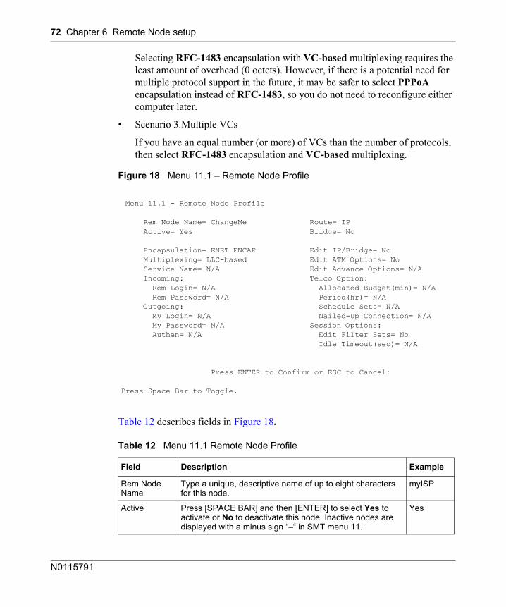
72 Chapter 6 Remote Node setup
N0115791
Selecting RFC-1483 encapsulation with VC-based multiplexing requires the least amount of overhead (0 octets). However, if there is a potential need for multiple protocol support in the future, it may be safer to select PPPoA encapsulation instead of RFC-1483, so you do not need to reconfigure either computer later.
• Scenario 3.Multiple VCs
If you have an equal number (or more) of VCs than the number of protocols, then select RFC-1483 encapsulation and VC-based multiplexing.
Figure 18 Menu 11.1 – Remote Node Profile
Table 12 describes fields in Figure 18.
Menu 11.1 - Remote Node Profile
Rem Node Name= ChangeMe Route= IP Active= Yes Bridge= No
Encapsulation= ENET ENCAP Edit IP/Bridge= No Multiplexing= LLC-based Edit ATM Options= No Service Name= N/A Edit Advance Options= N/A Incoming: Telco Option: Rem Login= N/A Allocated Budget(min)= N/A Rem Password= N/A Period(hr)= N/A Outgoing: Schedule Sets= N/A My Login= N/A Nailed-Up Connection= N/A My Password= N/A Session Options: Authen= N/A Edit Filter Sets= No Idle Timeout(sec)= N/A
Press ENTER to Confirm or ESC to Cancel:
Press Space Bar to Toggle.
Table 12 Menu 11.1 Remote Node Profile
Field Description Example
Rem Node Name
Type a unique, descriptive name of up to eight characters for this node.
myISP
Active Press [SPACE BAR] and then [ENTER] to select Yes to activate or No to deactivate this node. Inactive nodes are displayed with a minus sign “–“ in SMT menu 11.
Yes
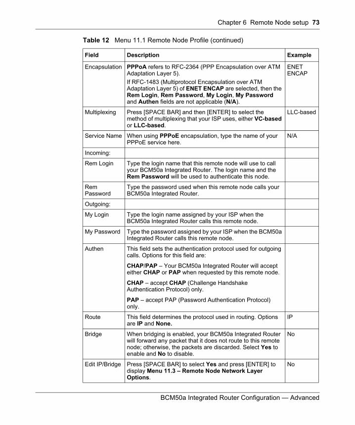
Chapter 6 Remote Node setup 73
BCM50a Integrated Router Configuration — Advanced
Encapsulation PPPoA refers to RFC-2364 (PPP Encapsulation over ATM Adaptation Layer 5). If RFC-1483 (Multiprotocol Encapsulation over ATM Adaptation Layer 5) of ENET ENCAP are selected, then the Rem Login, Rem Password, My Login, My Password and Authen fields are not applicable (N/A).
ENET ENCAP
Multiplexing Press [SPACE BAR] and then [ENTER] to select the method of multiplexing that your ISP uses, either VC-based or LLC-based.
LLC-based
Service Name When using PPPoE encapsulation, type the name of your PPPoE service here.
N/A
Incoming:
Rem Login Type the login name that this remote node will use to call your BCM50a Integrated Router. The login name and the Rem Password will be used to authenticate this node.
Rem Password
Type the password used when this remote node calls your BCM50a Integrated Router.
Outgoing:
My Login Type the login name assigned by your ISP when the BCM50a Integrated Router calls this remote node.
My Password Type the password assigned by your ISP when the BCM50a Integrated Router calls this remote node.
Authen This field sets the authentication protocol used for outgoing calls. Options for this field are:
CHAP/PAP – Your BCM50a Integrated Router will accept either CHAP or PAP when requested by this remote node.
CHAP – accept CHAP (Challenge Handshake Authentication Protocol) only.
PAP – accept PAP (Password Authentication Protocol) only.
Route This field determines the protocol used in routing. Options are IP and None.
IP
Bridge When bridging is enabled, your BCM50a Integrated Router will forward any packet that it does not route to this remote node; otherwise, the packets are discarded. Select Yes to enable and No to disable.
No
Edit IP/Bridge Press [SPACE BAR] to select Yes and press [ENTER] to display Menu 11.3 – Remote Node Network Layer Options.
No
Table 12 Menu 11.1 Remote Node Profile (continued)
Field Description Example
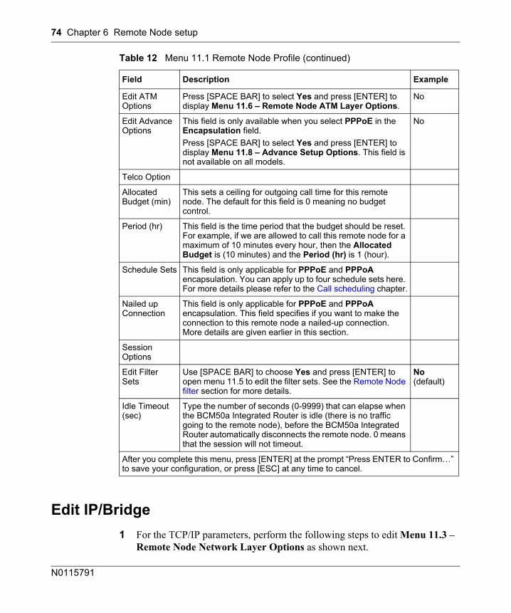
74 Chapter 6 Remote Node setup
N0115791
Edit IP/Bridge1 For the TCP/IP parameters, perform the following steps to edit Menu 11.3 –
Remote Node Network Layer Options as shown next.
Edit ATM Options
Press [SPACE BAR] to select Yes and press [ENTER] to display Menu 11.6 – Remote Node ATM Layer Options.
No
Edit Advance Options
This field is only available when you select PPPoE in the Encapsulation field.Press [SPACE BAR] to select Yes and press [ENTER] to display Menu 11.8 – Advance Setup Options. This field is not available on all models.
No
Telco Option
Allocated Budget (min)
This sets a ceiling for outgoing call time for this remote node. The default for this field is 0 meaning no budget control.
Period (hr) This field is the time period that the budget should be reset. For example, if we are allowed to call this remote node for a maximum of 10 minutes every hour, then the Allocated Budget is (10 minutes) and the Period (hr) is 1 (hour).
Schedule Sets This field is only applicable for PPPoE and PPPoA encapsulation. You can apply up to four schedule sets here. For more details please refer to the Call scheduling chapter.
Nailed up Connection
This field is only applicable for PPPoE and PPPoA encapsulation. This field specifies if you want to make the connection to this remote node a nailed-up connection. More details are given earlier in this section.
Session Options
Edit Filter Sets
Use [SPACE BAR] to choose Yes and press [ENTER] to open menu 11.5 to edit the filter sets. See the Remote Node filter section for more details.
No (default)
Idle Timeout (sec)
Type the number of seconds (0-9999) that can elapse when the BCM50a Integrated Router is idle (there is no traffic going to the remote node), before the BCM50a Integrated Router automatically disconnects the remote node. 0 means that the session will not timeout.
After you complete this menu, press [ENTER] at the prompt “Press ENTER to Confirm…” to save your configuration, or press [ESC] at any time to cancel.
Table 12 Menu 11.1 Remote Node Profile (continued)
Field Description Example
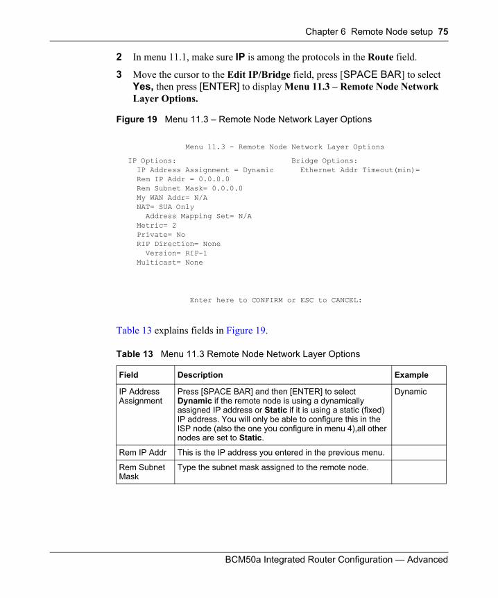
Chapter 6 Remote Node setup 75
BCM50a Integrated Router Configuration — Advanced
2 In menu 11.1, make sure IP is among the protocols in the Route field.
3 Move the cursor to the Edit IP/Bridge field, press [SPACE BAR] to select Yes, then press [ENTER] to display Menu 11.3 – Remote Node Network Layer Options.
Figure 19 Menu 11.3 – Remote Node Network Layer Options
Table 13 explains fields in Figure 19.
Menu 11.3 - Remote Node Network Layer Options
IP Options: Bridge Options: IP Address Assignment = Dynamic Ethernet Addr Timeout(min)= Rem IP Addr = 0.0.0.0 Rem Subnet Mask= 0.0.0.0 My WAN Addr= N/A NAT= SUA Only Address Mapping Set= N/A Metric= 2 Private= No RIP Direction= None Version= RIP-1 Multicast= None
Enter here to CONFIRM or ESC to CANCEL:
Table 13 Menu 11.3 Remote Node Network Layer Options
Field Description Example
IP Address Assignment
Press [SPACE BAR] and then [ENTER] to select Dynamic if the remote node is using a dynamically assigned IP address or Static if it is using a static (fixed) IP address. You will only be able to configure this in the ISP node (also the one you configure in menu 4),all other nodes are set to Static.
Dynamic
Rem IP Addr This is the IP address you entered in the previous menu.
Rem Subnet Mask
Type the subnet mask assigned to the remote node.
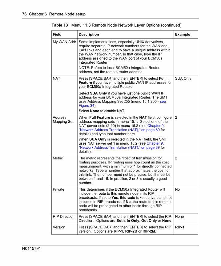
76 Chapter 6 Remote Node setup
N0115791
My WAN Addr Some implementations, especially UNIX derivatives, require separate IP network numbers for the WAN and LAN links and each end to have a unique address within the WAN network number. In that case, type the IP address assigned to the WAN port of your BCM50a Integrated Router.NOTE: Refers to local BCM50a Integrated Router address, not the remote router address.
NAT Press [SPACE BAR] and then [ENTER] to select Full Feature if you have multiple public WAN IP addresses for your BCM50a Integrated Router.
SUA Only
Select SUA Only if you have just one public WAN IP address for your BCM50a Integrated Router. The SMT uses Address Mapping Set 255 (menu 15.1.255 - see Figure 34). Select None to disable NAT.
Address Mapping Set
When Full Feature is selected in the NAT field, configure address mapping sets in menu 15.1. Select one of the NAT server sets (2-10) in menu 15.2 (see Chapter 9, “Network Address Translation (NAT),” on page 89 for details) and type that number here.When SUA Only is selected in the NAT field, the SMT uses NAT server set 1 in menu 15.2 (see Chapter 9, “Network Address Translation (NAT),” on page 89 for details).
2
Metric The metric represents the “cost” of transmission for routing purposes. IP routing uses hop count as the cost measurement, with a minimum of 1 for directly connected networks. Type a number that approximates the cost for this link. The number need not be precise, but it must be between 1 and 15. In practice, 2 or 3 is usually a good number.
2
Private This determines if the BCM50a Integrated Router will include the route to this remote node in its RIP broadcasts. If set to Yes, this route is kept private and not included in RIP broadcast. If No, the route to this remote node will be propagated to other hosts through RIP broadcasts.
No
RIP Direction Press [SPACE BAR] and then [ENTER] to select the RIP Direction. Options are Both, In Only, Out Only or None.
None
Version Press [SPACE BAR] and then [ENTER] to select the RIP version. Options are RIP-1, RIP-2B or RIP-2M.
RIP-1
Table 13 Menu 11.3 Remote Node Network Layer Options (continued)
Field Description Example
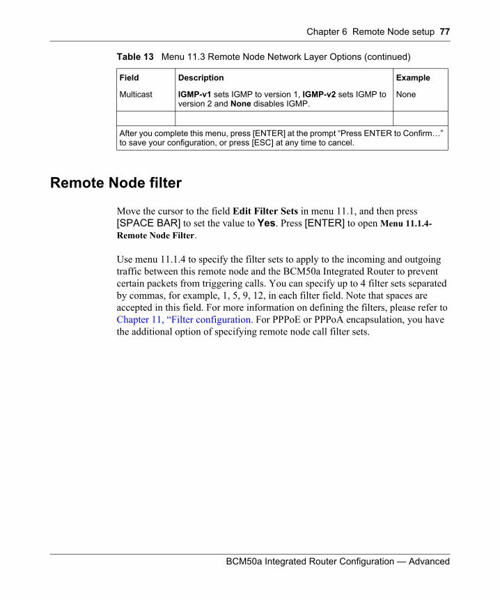
Chapter 6 Remote Node setup 77
BCM50a Integrated Router Configuration — Advanced
Remote Node filter
Move the cursor to the field Edit Filter Sets in menu 11.1, and then press [SPACE BAR] to set the value to Yes. Press [ENTER] to open Menu 11.1.4- Remote Node Filter.
Use menu 11.1.4 to specify the filter sets to apply to the incoming and outgoing traffic between this remote node and the BCM50a Integrated Router to prevent certain packets from triggering calls. You can specify up to 4 filter sets separated by commas, for example, 1, 5, 9, 12, in each filter field. Note that spaces are accepted in this field. For more information on defining the filters, please refer to Chapter 11, “Filter configuration. For PPPoE or PPPoA encapsulation, you have the additional option of specifying remote node call filter sets.
Multicast IGMP-v1 sets IGMP to version 1, IGMP-v2 sets IGMP to version 2 and None disables IGMP.
None
After you complete this menu, press [ENTER] at the prompt “Press ENTER to Confirm…” to save your configuration, or press [ESC] at any time to cancel.
Table 13 Menu 11.3 Remote Node Network Layer Options (continued)
Field Description Example
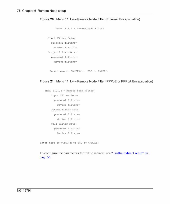
78 Chapter 6 Remote Node setup
N0115791
Figure 20 Menu 11.1.4 – Remote Node Filter (Ethernet Encapsulation)
Figure 21 Menu 11.1.4 – Remote Node Filter (PPPoE or PPPoA Encapsulation)
To configure the parameters for traffic redirect, see “Traffic redirect setup” on page 55.
Menu 11.1.4 - Remote Node Filter
Input Filter Sets:
protocol filters=
device filters=
Output Filter Sets:
protocol filters=
device filters=
Enter here to CONFIRM or ESC to CANCEL:
Menu 11.1.4 - Remote Node Filter
Input Filter Sets:
protocol filters=
Device filters=
Output Filter Sets:
protocol filters=
device filters=
Call Filter Sets:
protocol filters=
Device filters=
Enter here to CONFIRM or ESC to CANCEL:
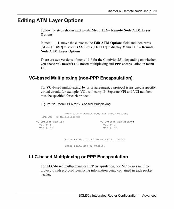
Chapter 6 Remote Node setup 79
BCM50a Integrated Router Configuration — Advanced
Editing ATM Layer Options
Follow the steps shown next to edit Menu 11.6 – Remote Node ATM Layer Options.
In menu 11.1, move the cursor to the Edit ATM Options field and then press [SPACE BAR] to select Yes. Press [ENTER] to display Menu 11.6 – Remote Node ATM Layer Options.
There are two versions of menu 11.6 for the Contivity 251, depending on whether you chose VC-based/LLC-based multiplexing and PPP encapsulation in menu 11.1.
VC-based Multiplexing (non-PPP Encapsulation)
For VC-based multiplexing, by prior agreement, a protocol is assigned a specific virtual circuit, for example, VC1 will carry IP. Separate VPI and VCI numbers must be specified for each protocol.
Figure 22 Menu 11.6 for VC-based Multiplexing
LLC-based Multiplexing or PPP Encapsulation
For LLC-based multiplexing or PPP encapsulation, one VC carries multiple protocols with protocol identifying information being contained in each packet header.
Menu 11.6 - Remote Node ATM Layer OptionsVPI/VCI (VC-Multiplexing)
VC Options for IP: VPI #= 8 VCI #= 35
VC Options for Bridge: VPI #= 1 VCI #= 36
Press ENTER to Confirm or ESC to Cancel:
Press Space Bar to Toggle.
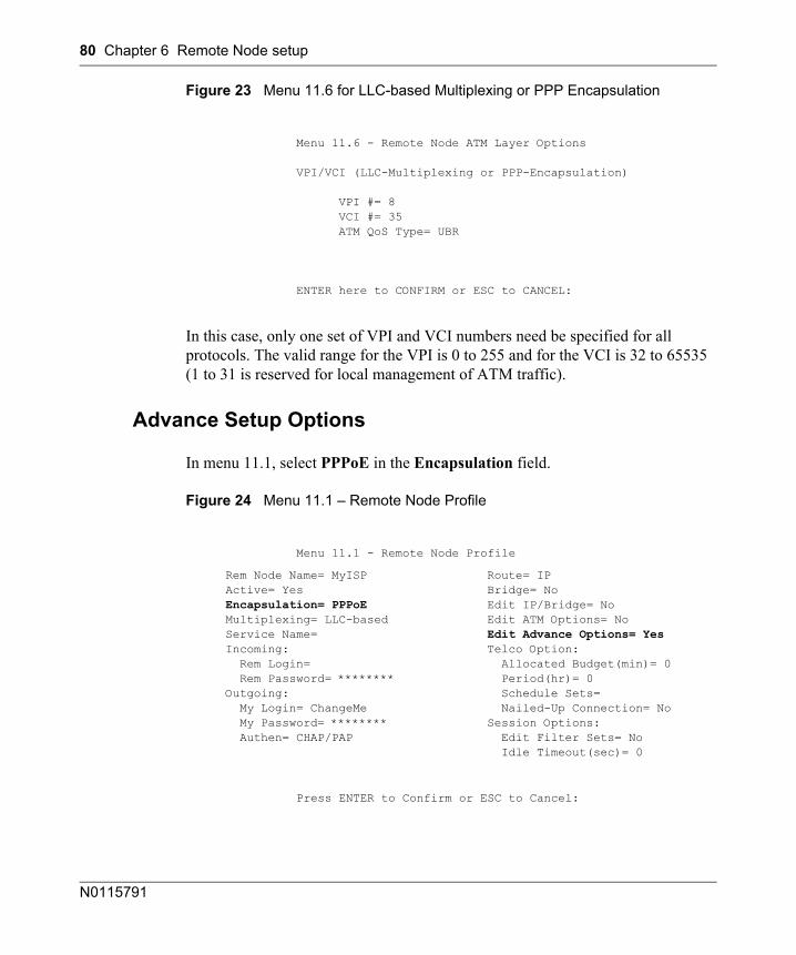
80 Chapter 6 Remote Node setup
N0115791
Figure 23 Menu 11.6 for LLC-based Multiplexing or PPP Encapsulation
In this case, only one set of VPI and VCI numbers need be specified for all protocols. The valid range for the VPI is 0 to 255 and for the VCI is 32 to 65535 (1 to 31 is reserved for local management of ATM traffic).
Advance Setup Options
In menu 11.1, select PPPoE in the Encapsulation field.
Figure 24 Menu 11.1 – Remote Node Profile
Menu 11.6 - Remote Node ATM Layer Options
VPI/VCI (LLC-Multiplexing or PPP-Encapsulation)
VPI #= 8 VCI #= 35 ATM QoS Type= UBR
ENTER here to CONFIRM or ESC to CANCEL:
Menu 11.1 - Remote Node Profile
Rem Node Name= MyISP Route= IP Active= Yes Bridge= No Encapsulation= PPPoE Edit IP/Bridge= No Multiplexing= LLC-based Edit ATM Options= No Service Name= Edit Advance Options= Yes Incoming: Telco Option: Rem Login= Allocated Budget(min)= 0 Rem Password= ******** Period(hr)= 0 Outgoing: Schedule Sets= My Login= ChangeMe Nailed-Up Connection= No My Password= ******** Session Options: Authen= CHAP/PAP Edit Filter Sets= No Idle Timeout(sec)= 0
Press ENTER to Confirm or ESC to Cancel:
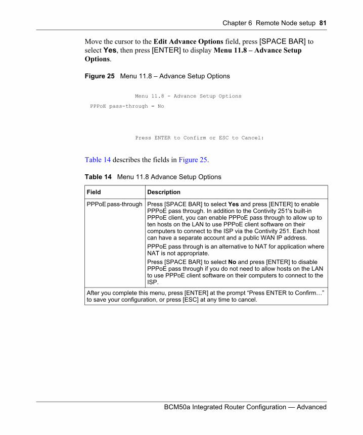
Chapter 6 Remote Node setup 81
BCM50a Integrated Router Configuration — Advanced
Move the cursor to the Edit Advance Options field, press [SPACE BAR] to select Yes, then press [ENTER] to display Menu 11.8 – Advance Setup Options.
Figure 25 Menu 11.8 – Advance Setup Options
Table 14 describes the fields in Figure 25.
Menu 11.8 - Advance Setup Options
PPPoE pass-through = No
Press ENTER to Confirm or ESC to Cancel:
Table 14 Menu 11.8 Advance Setup Options
Field Description
PPPoE pass-through Press [SPACE BAR] to select Yes and press [ENTER] to enable PPPoE pass through. In addition to the Contivity 251's built-in PPPoE client, you can enable PPPoE pass through to allow up to ten hosts on the LAN to use PPPoE client software on their computers to connect to the ISP via the Contivity 251. Each host can have a separate account and a public WAN IP address. PPPoE pass through is an alternative to NAT for application where NAT is not appropriate.Press [SPACE BAR] to select No and press [ENTER] to disable PPPoE pass through if you do not need to allow hosts on the LAN to use PPPoE client software on their computers to connect to the ISP.
After you complete this menu, press [ENTER] at the prompt “Press ENTER to Confirm…” to save your configuration, or press [ESC] at any time to cancel.

82 Chapter 6 Remote Node setup
N0115791
83
BCM50a Integrated Router Configuration — Advanced
Chapter 7IP Static Route Setup
This chapter shows you how to configure static routes with your BCM50a Integrated Router.
IP Static Route Setup
Enter 12 from the main menu. Select one of the IP static routes as shown in Figure 26 to configure IP static routes in menu 12. 1.
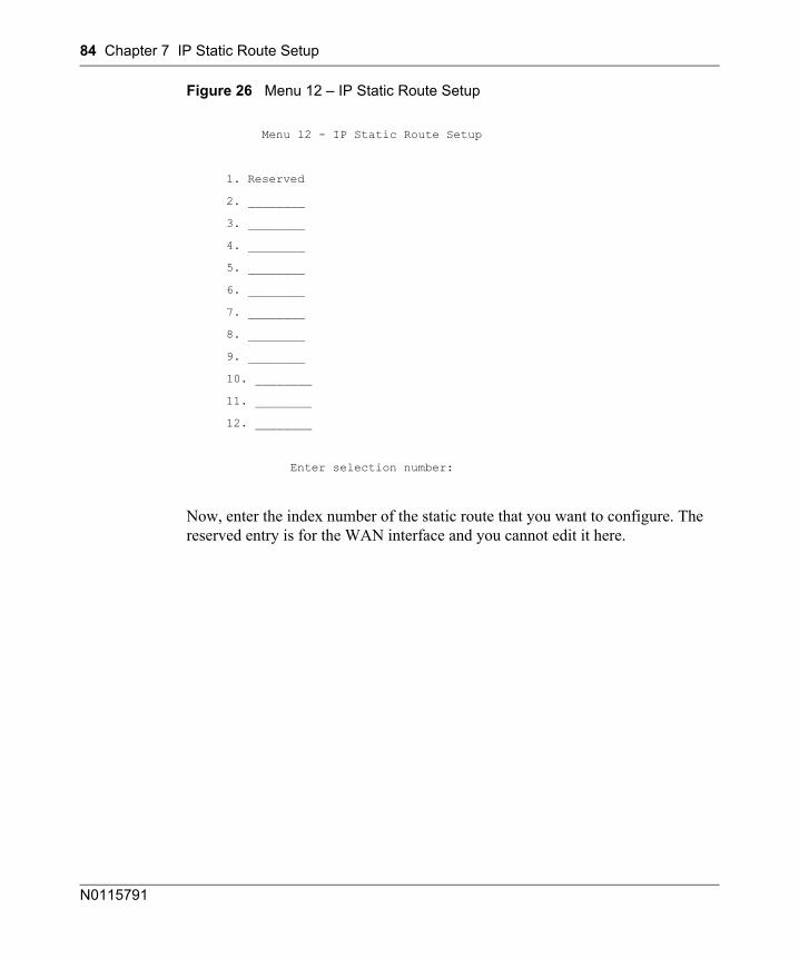
84 Chapter 7 IP Static Route Setup
N0115791
Figure 26 Menu 12 – IP Static Route Setup
Now, enter the index number of the static route that you want to configure. The reserved entry is for the WAN interface and you cannot edit it here.
Menu 12 - IP Static Route Setup
1. Reserved
2. ________
3. ________
4. ________
5. ________
6. ________
7. ________
8. ________
9. ________
10. ________
11. ________
12. ________
Enter selection number:
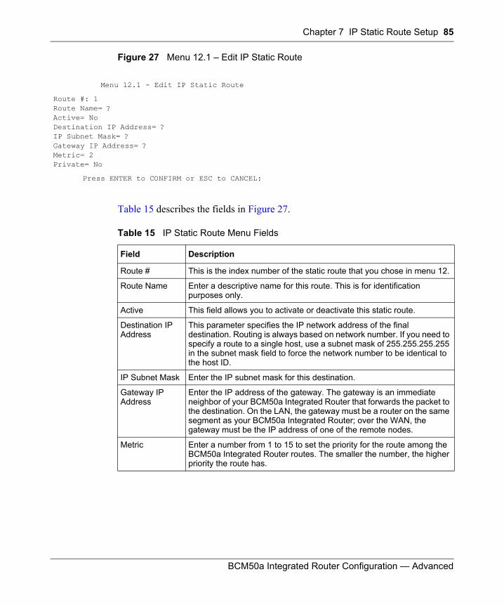
Chapter 7 IP Static Route Setup 85
BCM50a Integrated Router Configuration — Advanced
Figure 27 Menu 12.1 – Edit IP Static Route
Table 15 describes the fields in Figure 27.
Menu 12.1 - Edit IP Static Route
Route #: 1Route Name= ?Active= NoDestination IP Address= ?IP Subnet Mask= ?Gateway IP Address= ?Metric= 2Private= No
Press ENTER to CONFIRM or ESC to CANCEL:
Table 15 IP Static Route Menu Fields
Field Description
Route # This is the index number of the static route that you chose in menu 12.
Route Name Enter a descriptive name for this route. This is for identification purposes only.
Active This field allows you to activate or deactivate this static route.
Destination IP Address
This parameter specifies the IP network address of the final destination. Routing is always based on network number. If you need to specify a route to a single host, use a subnet mask of 255.255.255.255 in the subnet mask field to force the network number to be identical to the host ID.
IP Subnet Mask Enter the IP subnet mask for this destination.
Gateway IP Address
Enter the IP address of the gateway. The gateway is an immediate neighbor of your BCM50a Integrated Router that forwards the packet to the destination. On the LAN, the gateway must be a router on the same segment as your BCM50a Integrated Router; over the WAN, the gateway must be the IP address of one of the remote nodes.
Metric Enter a number from 1 to 15 to set the priority for the route among the BCM50a Integrated Router routes. The smaller the number, the higher priority the route has.
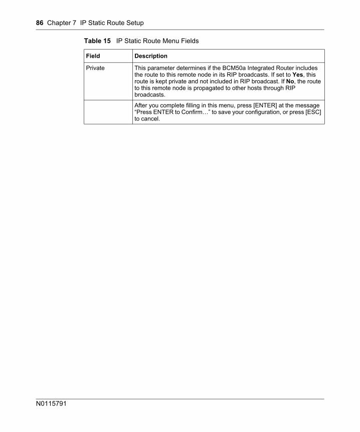
86 Chapter 7 IP Static Route Setup
N0115791
Private This parameter determines if the BCM50a Integrated Router includes the route to this remote node in its RIP broadcasts. If set to Yes, this route is kept private and not included in RIP broadcast. If No, the route to this remote node is propagated to other hosts through RIP broadcasts.
After you complete filling in this menu, press [ENTER] at the message “Press ENTER to Confirm…” to save your configuration, or press [ESC] to cancel.
Table 15 IP Static Route Menu Fields
Field Description
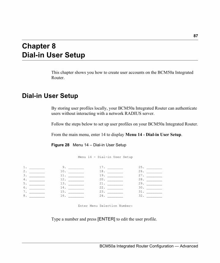
87
BCM50a Integrated Router Configuration — Advanced
Chapter 8Dial-in User Setup
This chapter shows you how to create user accounts on the BCM50a Integrated Router.
Dial-in User Setup
By storing user profiles locally, your BCM50a Integrated Router can authenticate users without interacting with a network RADIUS server.
Follow the steps below to set up user profiles on your BCM50a Integrated Router.
From the main menu, enter 14 to display Menu 14 - Dial-in User Setup.
Figure 28 Menu 14 – Dial-in User Setup
Type a number and press [ENTER] to edit the user profile.
Menu 14 - Dial-in User Setup
1. ________ 9. ________ 17. ________ 25. ________2. ________ 10. ________ 18. ________ 26. ________3. ________ 11. ________ 19. ________ 27. ________4. ________ 12. ________ 20. ________ 28. ________5. ________ 13. ________ 21. ________ 29. ________6. ________ 14. ________ 22. ________ 30. ________7. ________ 15. ________ 23. ________ 31. ________8. ________ 16. ________ 24. ________ 32. ________
Enter Menu Selection Number:
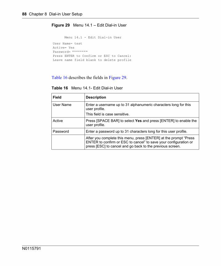
88 Chapter 8 Dial-in User Setup
N0115791
Figure 29 Menu 14.1 – Edit Dial-in User
Table 16 describes the fields in Figure 29.
Menu 14.1 - Edit Dial-in User
User Name= testActive= YesPassword= ********Press ENTER to Confirm or ESC to Cancel:Leave name field blank to delete profile
Table 16 Menu 14.1- Edit Dial-in User
Field Description
User Name Enter a username up to 31 alphanumeric characters long for this user profile.This field is case sensitive.
Active Press [SPACE BAR] to select Yes and press [ENTER] to enable the user profile.
Password Enter a password up to 31 characters long for this user profile.
After you complete this menu, press [ENTER] at the prompt “Press ENTER to confirm or ESC to cancel” to save your configuration or press [ESC] to cancel and go back to the previous screen.
89
BCM50a Integrated Router Configuration — Advanced
Chapter 9Network Address Translation (NAT)
This chapter discusses how to configure NAT on the BCM50a Integrated Router.
Using NAT
SUA (Single User Account) Versus NAT
SUA (Single User Account) is an implementation of a subset of NAT that supports two types of mapping, Many-to-One and Server. For a detailed description of NAT set for SUA, see“Address Mapping Sets” on page 92. The BCM50a Integrated Router also supports Full Feature NAT to map multiple global IP addresses to multiple private LAN IP addresses of clients or servers using mapping types.
Applying NAT
You apply NAT via menus 4 or 11.3 (Figure 31 on page 91). Figure 30 shows you how to apply NAT for Internet access in menu 4. Enter 4 from the main menu to go to Menu 4 - Internet Access Setup.
Note: You must create a firewall rule in addition to setting up SUA/NAT, to allow traffic from the WAN to be forwarded through the BCM50a Integrated Router.
Note: Choose SUA Only if you have just one public WAN IP address for your BCM50a Integrated Router.
Choose Full Feature if you have multiple public WAN IP addresses for your BCM50a Integrated Router.
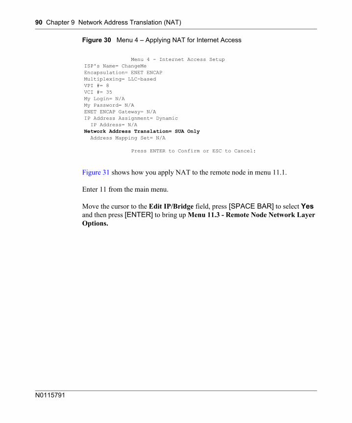
90 Chapter 9 Network Address Translation (NAT)
N0115791
Figure 30 Menu 4 – Applying NAT for Internet Access
Figure 31 shows how you apply NAT to the remote node in menu 11.1.
Enter 11 from the main menu.
Move the cursor to the Edit IP/Bridge field, press [SPACE BAR] to select Yes and then press [ENTER] to bring up Menu 11.3 - Remote Node Network Layer Options.
Menu 4 - Internet Access SetupISP's Name= ChangeMeEncapsulation= ENET ENCAPMultiplexing= LLC-basedVPI #= 8VCI #= 35My Login= N/AMy Password= N/AENET ENCAP Gateway= N/AIP Address Assignment= Dynamic IP Address= N/ANetwork Address Translation= SUA Only Address Mapping Set= N/A
Press ENTER to Confirm or ESC to Cancel:
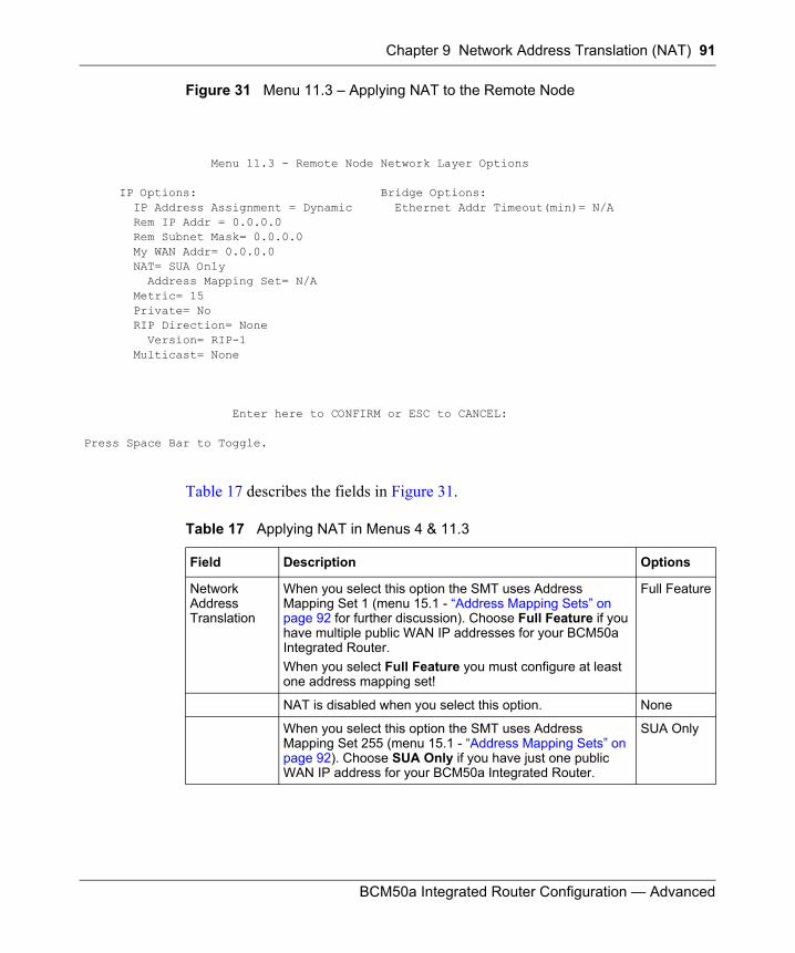
Chapter 9 Network Address Translation (NAT) 91
BCM50a Integrated Router Configuration — Advanced
Figure 31 Menu 11.3 – Applying NAT to the Remote Node
Table 17 describes the fields in Figure 31.
Menu 11.3 - Remote Node Network Layer Options
IP Options: Bridge Options: IP Address Assignment = Dynamic Ethernet Addr Timeout(min)= N/A Rem IP Addr = 0.0.0.0 Rem Subnet Mask= 0.0.0.0 My WAN Addr= 0.0.0.0 NAT= SUA Only Address Mapping Set= N/A Metric= 15 Private= No RIP Direction= None Version= RIP-1 Multicast= None
Enter here to CONFIRM or ESC to CANCEL:
Press Space Bar to Toggle.
Table 17 Applying NAT in Menus 4 & 11.3
Field Description Options
Network Address Translation
When you select this option the SMT uses Address Mapping Set 1 (menu 15.1 - “Address Mapping Sets” on page 92 for further discussion). Choose Full Feature if you have multiple public WAN IP addresses for your BCM50a Integrated Router.When you select Full Feature you must configure at least one address mapping set!
Full Feature
NAT is disabled when you select this option. None
When you select this option the SMT uses Address Mapping Set 255 (menu 15.1 - “Address Mapping Sets” on page 92). Choose SUA Only if you have just one public WAN IP address for your BCM50a Integrated Router.
SUA Only
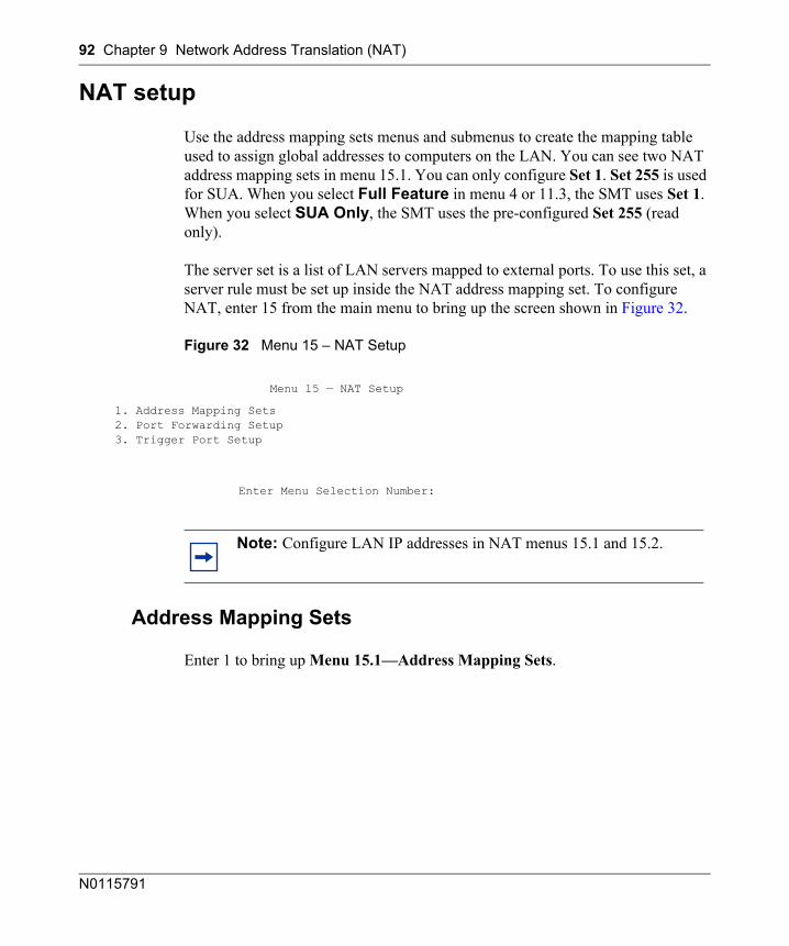
92 Chapter 9 Network Address Translation (NAT)
N0115791
NAT setup
Use the address mapping sets menus and submenus to create the mapping table used to assign global addresses to computers on the LAN. You can see two NAT address mapping sets in menu 15.1. You can only configure Set 1. Set 255 is used for SUA. When you select Full Feature in menu 4 or 11.3, the SMT uses Set 1. When you select SUA Only, the SMT uses the pre-configured Set 255 (read only).
The server set is a list of LAN servers mapped to external ports. To use this set, a server rule must be set up inside the NAT address mapping set. To configure NAT, enter 15 from the main menu to bring up the screen shown in Figure 32.
Figure 32 Menu 15 – NAT Setup
Address Mapping Sets
Enter 1 to bring up Menu 15.1—Address Mapping Sets.
Menu 15 — NAT Setup
1. Address Mapping Sets2. Port Forwarding Setup3. Trigger Port Setup
Enter Menu Selection Number:
Note: Configure LAN IP addresses in NAT menus 15.1 and 15.2.
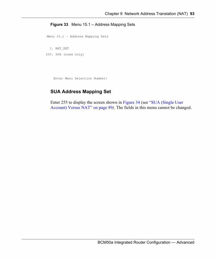
Chapter 9 Network Address Translation (NAT) 93
BCM50a Integrated Router Configuration — Advanced
Figure 33 Menu 15.1 – Address Mapping Sets
SUA Address Mapping Set
Enter 255 to display the screen shown in Figure 34 (see “SUA (Single User Account) Versus NAT” on page 89). The fields in this menu cannot be changed.
Menu 15.1 — Address Mapping Sets
1. NAT_SET
255. SUA (read only)
Enter Menu Selection Number:
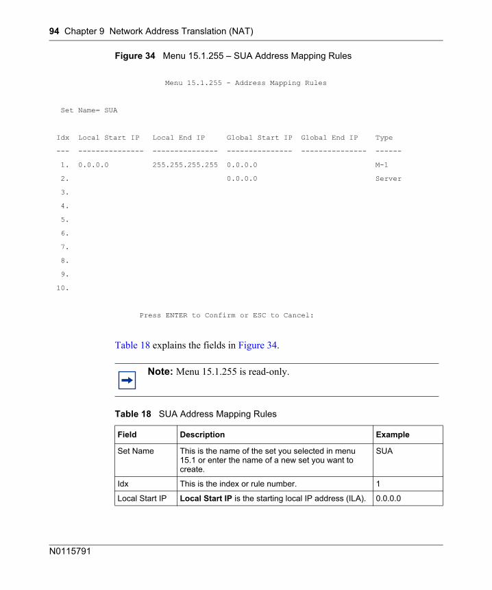
94 Chapter 9 Network Address Translation (NAT)
N0115791
Figure 34 Menu 15.1.255 – SUA Address Mapping Rules
Table 18 explains the fields in Figure 34.
Menu 15.1.255 - Address Mapping Rules
Set Name= SUA
Idx Local Start IP Local End IP Global Start IP Global End IP Type
--- --------------- --------------- --------------- --------------- ------
1. 0.0.0.0 255.255.255.255 0.0.0.0 M-1
2. 0.0.0.0 Server
3.
4.
5.
6.
7.
8.
9.
10.
Press ENTER to Confirm or ESC to Cancel:
Note: Menu 15.1.255 is read-only.
Table 18 SUA Address Mapping Rules
Field Description Example
Set Name This is the name of the set you selected in menu 15.1 or enter the name of a new set you want to create.
SUA
Idx This is the index or rule number. 1
Local Start IP Local Start IP is the starting local IP address (ILA). 0.0.0.0
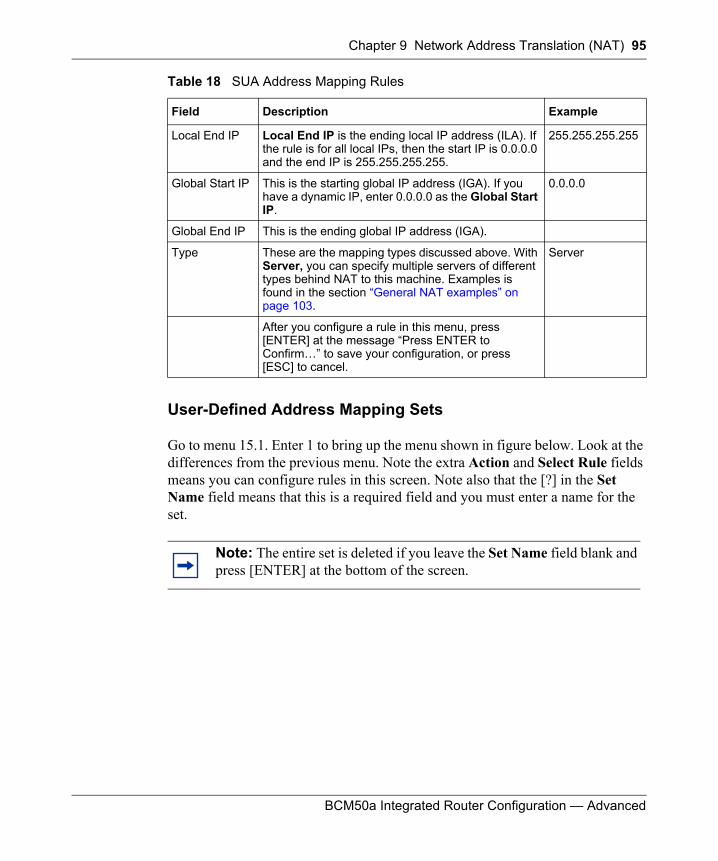
Chapter 9 Network Address Translation (NAT) 95
BCM50a Integrated Router Configuration — Advanced
User-Defined Address Mapping Sets
Go to menu 15.1. Enter 1 to bring up the menu shown in figure below. Look at the differences from the previous menu. Note the extra Action and Select Rule fields means you can configure rules in this screen. Note also that the [?] in the Set Name field means that this is a required field and you must enter a name for the set.
Local End IP Local End IP is the ending local IP address (ILA). If the rule is for all local IPs, then the start IP is 0.0.0.0 and the end IP is 255.255.255.255.
255.255.255.255
Global Start IP This is the starting global IP address (IGA). If you have a dynamic IP, enter 0.0.0.0 as the Global Start IP.
0.0.0.0
Global End IP This is the ending global IP address (IGA).
Type These are the mapping types discussed above. With Server, you can specify multiple servers of different types behind NAT to this machine. Examples is found in the section “General NAT examples” on page 103.
Server
After you configure a rule in this menu, press [ENTER] at the message “Press ENTER to Confirm…” to save your configuration, or press [ESC] to cancel.
Note: The entire set is deleted if you leave the Set Name field blank and press [ENTER] at the bottom of the screen.
Table 18 SUA Address Mapping Rules
Field Description Example
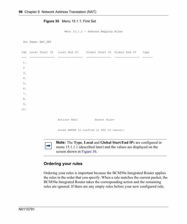
96 Chapter 9 Network Address Translation (NAT)
N0115791
Figure 35 Menu 15.1.1: First Set
Ordering your rules
Ordering your rules is important because the BCM50a Integrated Router applies the rules in the order that you specify. When a rule matches the current packet, the BCM50a Integrated Router takes the corresponding action and the remaining rules are ignored. If there are any empty rules before your new configured rule,
Menu 15.1.1 - Address Mapping Rules
Set Name= NAT_SET
Idx Local Start IP Local End IP Global Start IP Global End IP Type
--- --------------- --------------- --------------- --------------- ------
1.
2
3.
4.
5.
6.
7.
8.
9.
10.
Action= Edit Select Rule=
Press ENTER to Confirm or ESC to Cancel:
Note: The Type, Local and Global Start/End IPs are configured in menu 15.1.1.1 (described later) and the values are displayed on the screen shown in Figure 36.
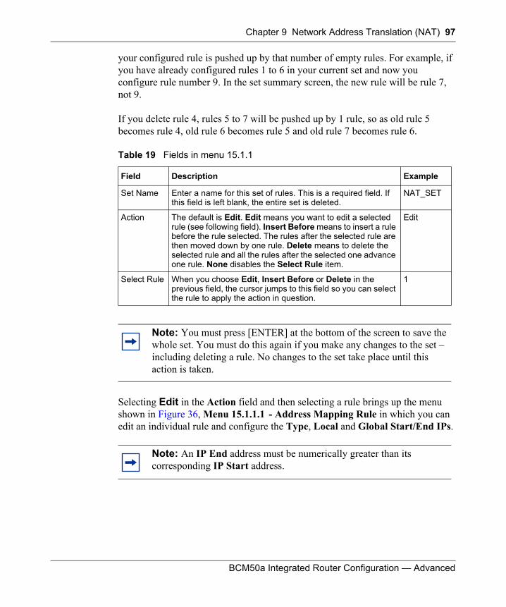
Chapter 9 Network Address Translation (NAT) 97
BCM50a Integrated Router Configuration — Advanced
your configured rule is pushed up by that number of empty rules. For example, if you have already configured rules 1 to 6 in your current set and now you configure rule number 9. In the set summary screen, the new rule will be rule 7, not 9.
If you delete rule 4, rules 5 to 7 will be pushed up by 1 rule, so as old rule 5 becomes rule 4, old rule 6 becomes rule 5 and old rule 7 becomes rule 6.
Selecting Edit in the Action field and then selecting a rule brings up the menu shown in Figure 36, Menu 15.1.1.1 - Address Mapping Rule in which you can edit an individual rule and configure the Type, Local and Global Start/End IPs.
Table 19 Fields in menu 15.1.1
Field Description Example
Set Name Enter a name for this set of rules. This is a required field. If this field is left blank, the entire set is deleted.
NAT_SET
Action The default is Edit. Edit means you want to edit a selected rule (see following field). Insert Before means to insert a rule before the rule selected. The rules after the selected rule are then moved down by one rule. Delete means to delete the selected rule and all the rules after the selected one advance one rule. None disables the Select Rule item.
Edit
Select Rule When you choose Edit, Insert Before or Delete in the previous field, the cursor jumps to this field so you can select the rule to apply the action in question.
1
Note: You must press [ENTER] at the bottom of the screen to save the whole set. You must do this again if you make any changes to the set – including deleting a rule. No changes to the set take place until this action is taken.
Note: An IP End address must be numerically greater than its corresponding IP Start address.
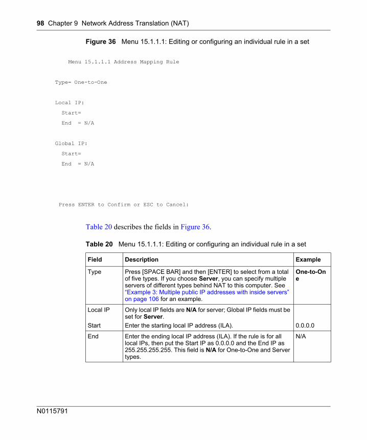
98 Chapter 9 Network Address Translation (NAT)
N0115791
Figure 36 Menu 15.1.1.1: Editing or configuring an individual rule in a set
Table 20 describes the fields in Figure 36.
Menu 15.1.1.1 Address Mapping Rule
Type= One-to-One
Local IP:
Start=
End = N/A
Global IP:
Start=
End = N/A
Press ENTER to Confirm or ESC to Cancel:
Table 20 Menu 15.1.1.1: Editing or configuring an individual rule in a set
Field Description Example
Type Press [SPACE BAR] and then [ENTER] to select from a total of five types. If you choose Server, you can specify multiple servers of different types behind NAT to this computer. See “Example 3: Multiple public IP addresses with inside servers” on page 106 for an example.
One-to-One
Local IP
Start
Only local IP fields are N/A for server; Global IP fields must be set for Server.Enter the starting local IP address (ILA). 0.0.0.0
End Enter the ending local IP address (ILA). If the rule is for all local IPs, then put the Start IP as 0.0.0.0 and the End IP as 255.255.255.255. This field is N/A for One-to-One and Server types.
N/A
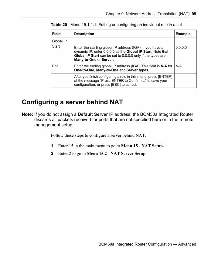
Chapter 9 Network Address Translation (NAT) 99
BCM50a Integrated Router Configuration — Advanced
Configuring a server behind NAT
Note: If you do not assign a Default Server IP address, the BCM50a Integrated Router discards all packets received for ports that are not specified here or in the remote management setup.
Follow these steps to configure a server behind NAT:
1 Enter 15 in the main menu to go to Menu 15 - NAT Setup.
2 Enter 2 to go to Menu 15.2 - NAT Server Setup.
Global IPStart Enter the starting global IP address (IGA). If you have a
dynamic IP, enter 0.0.0.0 as the Global IP Start. Note that Global IP Start can be set to 0.0.0.0 only if the types are Many-to-One or Server.
0.0.0.0
End Enter the ending global IP address (IGA). This field is N/A for One-to-One, Many-to-One and Server types.
N/A
After you finish configuring a rule in this menu, press [ENTER] at the message “Press ENTER to Confirm…” to save your configuration, or press [ESC] to cancel.
Table 20 Menu 15.1.1.1: Editing or configuring an individual rule in a set
Field Description Example
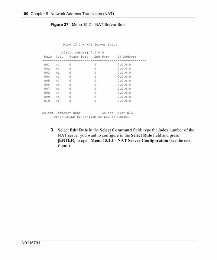
100 Chapter 9 Network Address Translation (NAT)
N0115791
Figure 37 Menu 15.2 – NAT Server Sets
3 Select Edit Rule in the Select Command field; type the index number of the NAT server you want to configure in the Select Rule field and press [ENTER] to open Menu 15.2.1 - NAT Server Configuration (see the next figure).
Menu 15.2 - NAT Server Setup
Default Server: 0.0.0.0 Rule Act. Start Port End Port IP Address ------------------------------------------------------ 001 No 0 0 0.0.0.0 002 No 0 0 0.0.0.0 003 No 0 0 0.0.0.0 004 No 0 0 0.0.0.0 005 No 0 0 0.0.0.0 006 No 0 0 0.0.0.0 007 No 0 0 0.0.0.0 008 No 0 0 0.0.0.0 009 No 0 0 0.0.0.0 010 No 0 0 0.0.0.0
Select Command= None Select Rule= N/A Press ENTER to Confirm or ESC to Cancel:
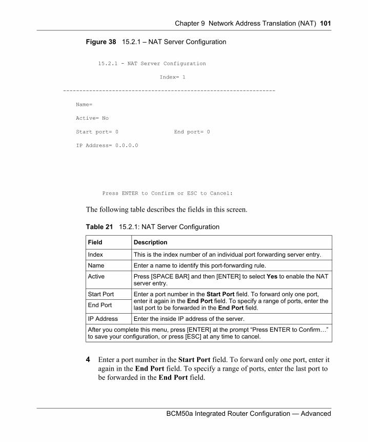
Chapter 9 Network Address Translation (NAT) 101
BCM50a Integrated Router Configuration — Advanced
Figure 38 15.2.1 – NAT Server Configuration
15.2.1 - NAT Server Configuration
Index= 1
-----------------------------------------------------------------
Name=
Active= No
Start port= 0 End port= 0
IP Address= 0.0.0.0
Press ENTER to Confirm or ESC to Cancel:
The following table describes the fields in this screen.
4 Enter a port number in the Start Port field. To forward only one port, enter it again in the End Port field. To specify a range of ports, enter the last port to be forwarded in the End Port field.
Table 21 15.2.1: NAT Server Configuration
Field Description
Index This is the index number of an individual port forwarding server entry.
Name Enter a name to identify this port-forwarding rule.
Active Press [SPACE BAR] and then [ENTER] to select Yes to enable the NAT server entry.
Start Port Enter a port number in the Start Port field. To forward only one port, enter it again in the End Port field. To specify a range of ports, enter the last port to be forwarded in the End Port field.End Port
IP Address Enter the inside IP address of the server.
After you complete this menu, press [ENTER] at the prompt “Press ENTER to Confirm…” to save your configuration, or press [ESC] at any time to cancel.
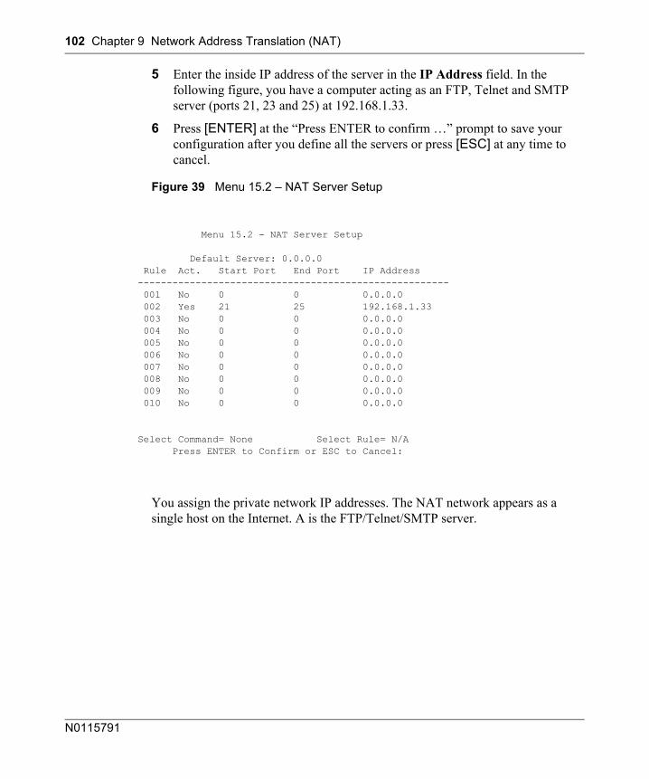
102 Chapter 9 Network Address Translation (NAT)
N0115791
5 Enter the inside IP address of the server in the IP Address field. In the following figure, you have a computer acting as an FTP, Telnet and SMTP server (ports 21, 23 and 25) at 192.168.1.33.
6 Press [ENTER] at the “Press ENTER to confirm …” prompt to save your configuration after you define all the servers or press [ESC] at any time to cancel.
Figure 39 Menu 15.2 – NAT Server Setup
You assign the private network IP addresses. The NAT network appears as a single host on the Internet. A is the FTP/Telnet/SMTP server.
Menu 15.2 - NAT Server Setup
Default Server: 0.0.0.0 Rule Act. Start Port End Port IP Address ------------------------------------------------------ 001 No 0 0 0.0.0.0 002 Yes 21 25 192.168.1.33 003 No 0 0 0.0.0.0 004 No 0 0 0.0.0.0 005 No 0 0 0.0.0.0 006 No 0 0 0.0.0.0 007 No 0 0 0.0.0.0 008 No 0 0 0.0.0.0 009 No 0 0 0.0.0.0 010 No 0 0 0.0.0.0
Select Command= None Select Rule= N/A Press ENTER to Confirm or ESC to Cancel:
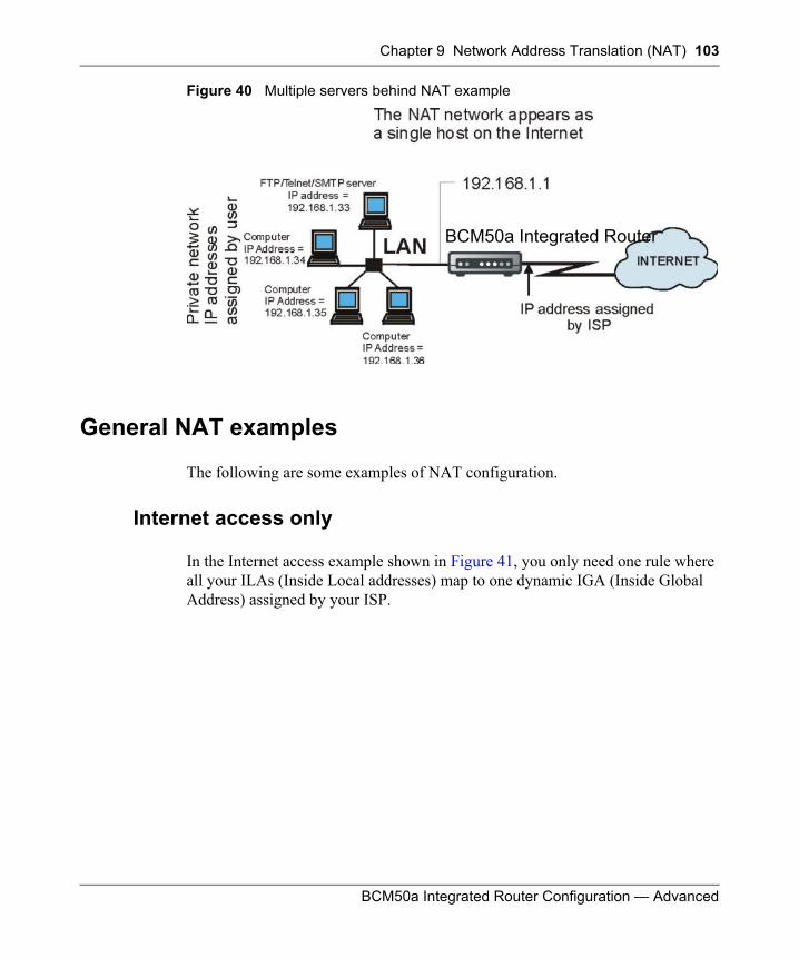
Chapter 9 Network Address Translation (NAT) 103
BCM50a Integrated Router Configuration — Advanced
Figure 40 Multiple servers behind NAT example
General NAT examples
The following are some examples of NAT configuration.
Internet access only
In the Internet access example shown in Figure 41, you only need one rule where all your ILAs (Inside Local addresses) map to one dynamic IGA (Inside Global Address) assigned by your ISP.
BCM50a Integrated Router
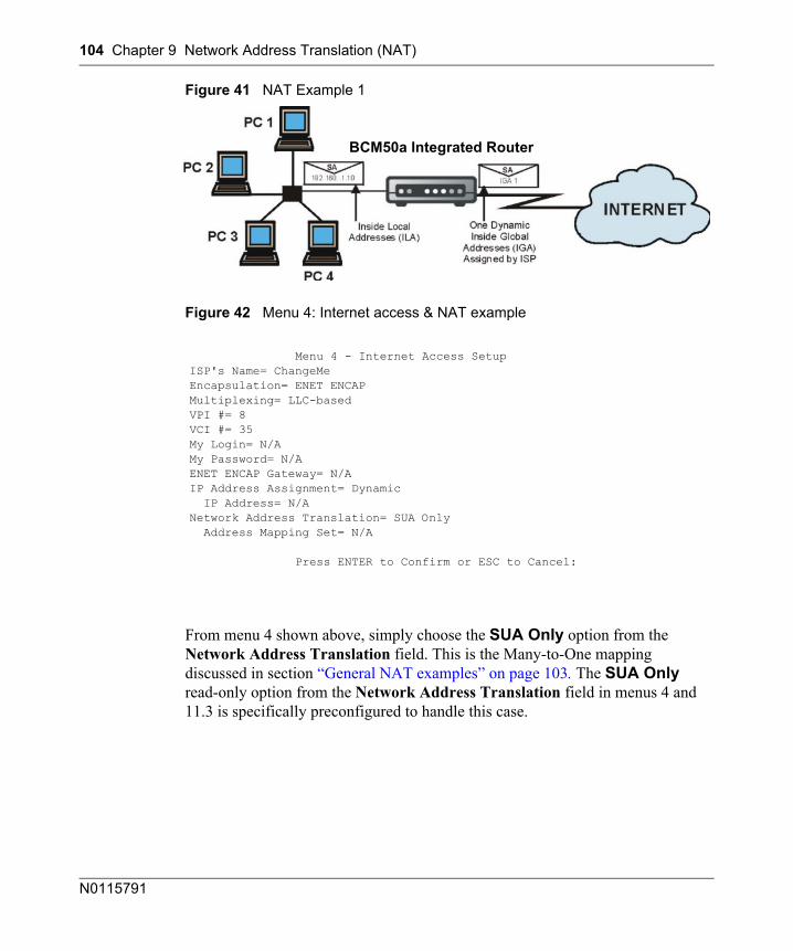
104 Chapter 9 Network Address Translation (NAT)
N0115791
Figure 41 NAT Example 1
Figure 42 Menu 4: Internet access & NAT example
From menu 4 shown above, simply choose the SUA Only option from the Network Address Translation field. This is the Many-to-One mapping discussed in section “General NAT examples” on page 103. The SUA Only read-only option from the Network Address Translation field in menus 4 and 11.3 is specifically preconfigured to handle this case.
Menu 4 - Internet Access SetupISP's Name= ChangeMeEncapsulation= ENET ENCAPMultiplexing= LLC-basedVPI #= 8VCI #= 35My Login= N/AMy Password= N/AENET ENCAP Gateway= N/AIP Address Assignment= Dynamic IP Address= N/ANetwork Address Translation= SUA Only Address Mapping Set= N/A
Press ENTER to Confirm or ESC to Cancel:
BCM50a Integrated Router
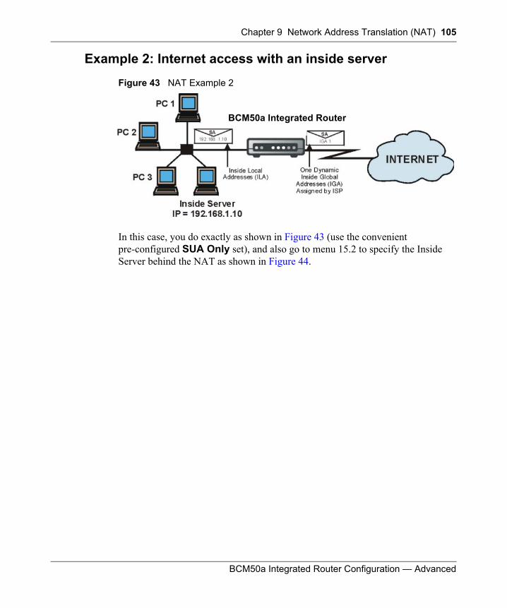
Chapter 9 Network Address Translation (NAT) 105
BCM50a Integrated Router Configuration — Advanced
Example 2: Internet access with an inside server
Figure 43 NAT Example 2
In this case, you do exactly as shown in Figure 43 (use the convenient pre-configured SUA Only set), and also go to menu 15.2 to specify the Inside Server behind the NAT as shown in Figure 44.
BCM50a Integrated Router
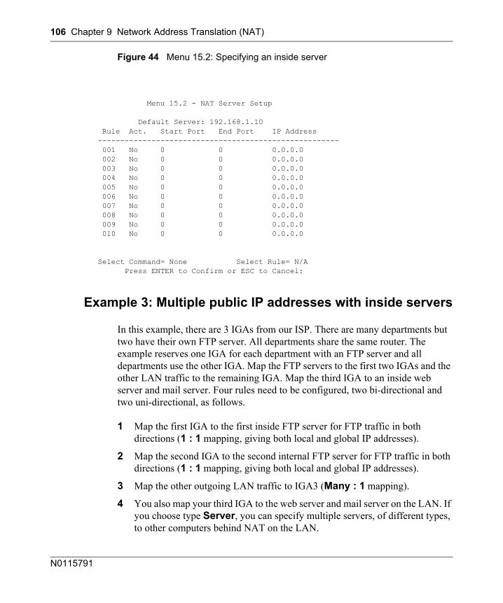
106 Chapter 9 Network Address Translation (NAT)
N0115791
Figure 44 Menu 15.2: Specifying an inside server
Example 3: Multiple public IP addresses with inside servers
In this example, there are 3 IGAs from our ISP. There are many departments but two have their own FTP server. All departments share the same router. The example reserves one IGA for each department with an FTP server and all departments use the other IGA. Map the FTP servers to the first two IGAs and the other LAN traffic to the remaining IGA. Map the third IGA to an inside web server and mail server. Four rules need to be configured, two bi-directional and two uni-directional, as follows.
1 Map the first IGA to the first inside FTP server for FTP traffic in both directions (1 : 1 mapping, giving both local and global IP addresses).
2 Map the second IGA to the second internal FTP server for FTP traffic in both directions (1 : 1 mapping, giving both local and global IP addresses).
3 Map the other outgoing LAN traffic to IGA3 (Many : 1 mapping).
4 You also map your third IGA to the web server and mail server on the LAN. If you choose type Server, you can specify multiple servers, of different types, to other computers behind NAT on the LAN.
Menu 15.2 - NAT Server Setup
Default Server: 192.168.1.10 Rule Act. Start Port End Port IP Address ------------------------------------------------------ 001 No 0 0 0.0.0.0 002 No 0 0 0.0.0.0 003 No 0 0 0.0.0.0 004 No 0 0 0.0.0.0 005 No 0 0 0.0.0.0 006 No 0 0 0.0.0.0 007 No 0 0 0.0.0.0 008 No 0 0 0.0.0.0 009 No 0 0 0.0.0.0 010 No 0 0 0.0.0.0
Select Command= None Select Rule= N/A Press ENTER to Confirm or ESC to Cancel:
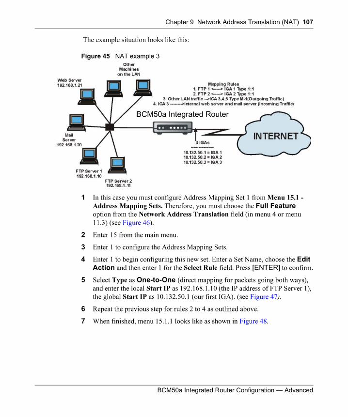
Chapter 9 Network Address Translation (NAT) 107
BCM50a Integrated Router Configuration — Advanced
The example situation looks like this:
Figure 45 NAT example 3
1 In this case you must configure Address Mapping Set 1 from Menu 15.1 - Address Mapping Sets. Therefore, you must choose the Full Feature option from the Network Address Translation field (in menu 4 or menu 11.3) (see Figure 46).
2 Enter 15 from the main menu.
3 Enter 1 to configure the Address Mapping Sets.
4 Enter 1 to begin configuring this new set. Enter a Set Name, choose the Edit Action and then enter 1 for the Select Rule field. Press [ENTER] to confirm.
5 Select Type as One-to-One (direct mapping for packets going both ways), and enter the local Start IP as 192.168.1.10 (the IP address of FTP Server 1), the global Start IP as 10.132.50.1 (our first IGA). (see Figure 47).
6 Repeat the previous step for rules 2 to 4 as outlined above.
7 When finished, menu 15.1.1 looks like as shown in Figure 48.
BCM50a Integrated Router
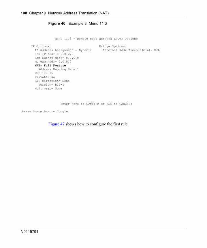
108 Chapter 9 Network Address Translation (NAT)
N0115791
Figure 46 Example 3: Menu 11.3
Figure 47 shows how to configure the first rule.
Menu 11.3 - Remote Node Network Layer Options
IP Options: Bridge Options: IP Address Assignment = Dynamic Ethernet Addr Timeout(min)= N/A Rem IP Addr = 0.0.0.0 Rem Subnet Mask= 0.0.0.0 My WAN Addr= 0.0.0.0 NAT= Full Feature Address Mapping Set= 1 Metric= 15 Private= No RIP Direction= None Version= RIP-1 Multicast= None
Enter here to CONFIRM or ESC to CANCEL:
Press Space Bar to Toggle.
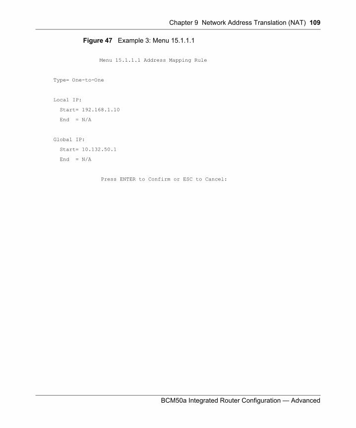
Chapter 9 Network Address Translation (NAT) 109
BCM50a Integrated Router Configuration — Advanced
Figure 47 Example 3: Menu 15.1.1.1
Menu 15.1.1.1 Address Mapping Rule
Type= One-to-One
Local IP:
Start= 192.168.1.10
End = N/A
Global IP:
Start= 10.132.50.1
End = N/A
Press ENTER to Confirm or ESC to Cancel:
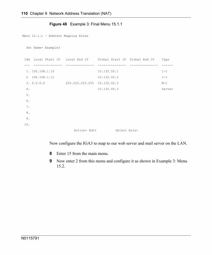
110 Chapter 9 Network Address Translation (NAT)
N0115791
Figure 48 Example 3: Final Menu 15.1.1
Now configure the IGA3 to map to our web server and mail server on the LAN.
8 Enter 15 from the main menu.
9 Now enter 2 from this menu and configure it as shown in Example 3: Menu 15.2.
Menu 15.1.1 - Address Mapping Rules
Set Name= Example3
Idx Local Start IP Local End IP Global Start IP Global End IP Type
--- --------------- --------------- --------------- --------------- ------
1. 192.168.1.10 10.132.50.1 1-1
2 192.168.1.11 10.132.50.2 1-1
3. 0.0.0.0 255.255.255.255 10.132.50.3 M-1
4. 10.132.50.3 Server
5.
6.
7.
8.
9.
10.
Action= Edit Select Rule=
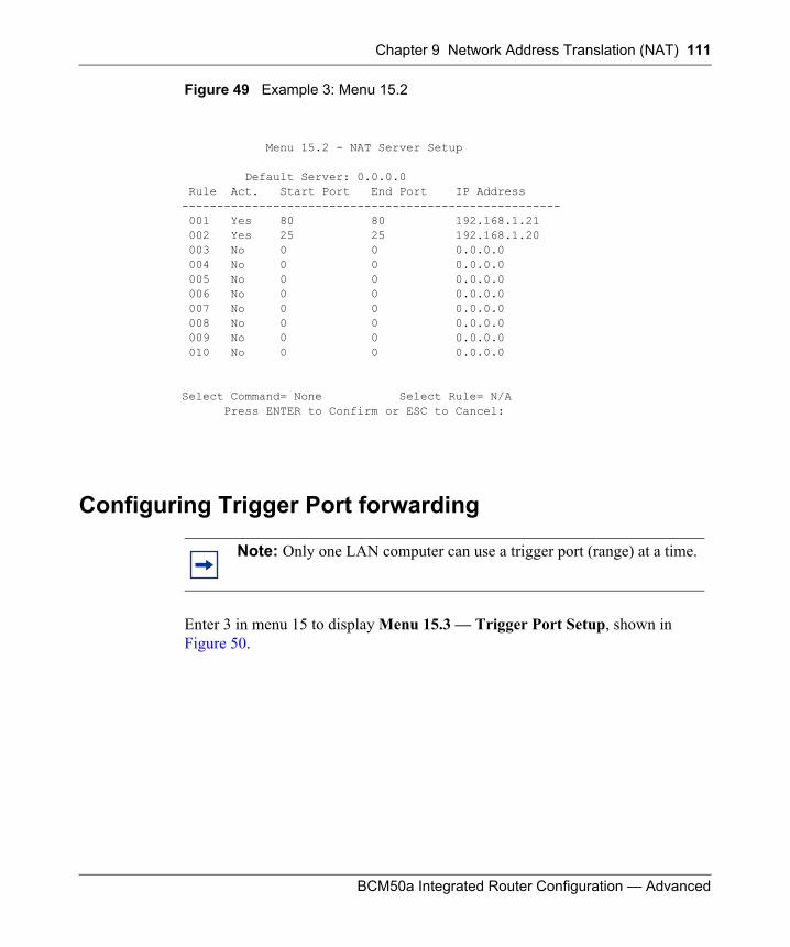
Chapter 9 Network Address Translation (NAT) 111
BCM50a Integrated Router Configuration — Advanced
Figure 49 Example 3: Menu 15.2
Configuring Trigger Port forwarding
Enter 3 in menu 15 to display Menu 15.3 — Trigger Port Setup, shown in Figure 50.
Menu 15.2 - NAT Server Setup
Default Server: 0.0.0.0 Rule Act. Start Port End Port IP Address ------------------------------------------------------ 001 Yes 80 80 192.168.1.21 002 Yes 25 25 192.168.1.20 003 No 0 0 0.0.0.0 004 No 0 0 0.0.0.0 005 No 0 0 0.0.0.0 006 No 0 0 0.0.0.0 007 No 0 0 0.0.0.0 008 No 0 0 0.0.0.0 009 No 0 0 0.0.0.0 010 No 0 0 0.0.0.0
Select Command= None Select Rule= N/A Press ENTER to Confirm or ESC to Cancel:
Note: Only one LAN computer can use a trigger port (range) at a time.
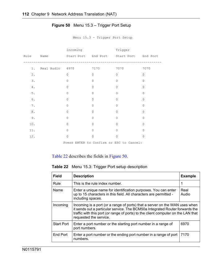
112 Chapter 9 Network Address Translation (NAT)
N0115791
Figure 50 Menu 15.3 – Trigger Port Setup
Table 22 describes the fields in Figure 50.
Menu 15.3 - Trigger Port Setup
Incoming Trigger
Rule Name Start Port End Port Start Port End Port
----------------------------------------------------------------------
1. Real Audio 6970 7170 7070 7070
2. 0 0 0 0
3. 0 0 0 0
4. 0 0 0 0
5. 0 0 0 0
6. 0 0 0 0
7. 0 0 0 0
8. 0 0 0 0
9. 0 0 0 0
10. 0 0 0 0
11. 0 0 0 0
12. 0 0 0 0
Press ENTER to Confirm or ESC to Cancel:
Table 22 Menu 15.3: Trigger Port setup description
Field Description Example
Rule This is the rule index number. 1
Name Enter a unique name for identification purposes. You can enter up to 15 characters in this field. All characters are permitted - including spaces.
Real Audio
Incoming Incoming is a port (or a range of ports) that a server on the WAN uses when it sends out a particular service. The BCM50a Integrated Router forwards the traffic with this port (or range of ports) to the client computer on the LAN that requested the service.
Start Port Enter a port number or the starting port number in a range of port numbers.
6970
End Port Enter a port number or the ending port number in a range of port numbers.
7170
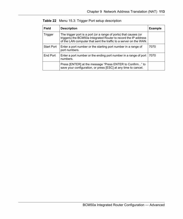
Chapter 9 Network Address Translation (NAT) 113
BCM50a Integrated Router Configuration — Advanced
Trigger The trigger port is a port (or a range of ports) that causes (or triggers) the BCM50a Integrated Router to record the IP address of the LAN computer that sent the traffic to a server on the WAN.
Start Port Enter a port number or the starting port number in a range of port numbers.
7070
End Port Enter a port number or the ending port number in a range of port numbers.
7070
Press [ENTER] at the message “Press ENTER to Confirm...” to save your configuration, or press [ESC] at any time to cancel.
Table 22 Menu 15.3: Trigger Port setup description
Field Description Example

114 Chapter 9 Network Address Translation (NAT)
N0115791
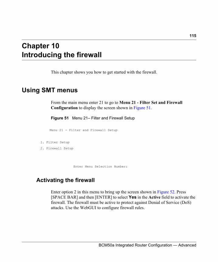
115
BCM50a Integrated Router Configuration — Advanced
Chapter 10Introducing the firewall
This chapter shows you how to get started with the firewall.
Using SMT menus
From the main menu enter 21 to go to Menu 21 - Filter Set and Firewall Configuration to display the screen shown in Figure 51.
Figure 51 Menu 21– Filter and Firewall Setup
Activating the firewall
Enter option 2 in this menu to bring up the screen shown in Figure 52. Press [SPACE BAR] and then [ENTER] to select Yes in the Active field to activate the firewall. The firewall must be active to protect against Denial of Service (DoS) attacks. Use the WebGUI to configure firewall rules.
Menu 21 - Filter and Firewall Setup
1. Filter Setup
2. Firewall Setup
Enter Menu Selection Number:
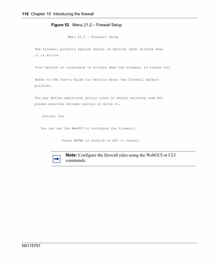
116 Chapter 10 Introducing the firewall
N0115791
Figure 52 Menu 21.2 – Firewall Setup
Menu 21.2 - Firewall Setup
The firewall protects against Denial of Service (DoS) attacks when
it is active.
Your network is vulnerable to attacks when the firewall is turned off.
Refer to the User’s Guide for details about the firewall default
policies.
You may define additional policy rules or modify existing ones but
please exercise extreme caution in doing so.
Active: Yes
You can use the WebGUI to configure the firewall.
Press ENTER to Confirm or ESC to Cancel:
Note: Configure the firewall rules using the WebGUI or CLI commands.
117
BCM50a Integrated Router Configuration — Advanced
Chapter 11Filter configuration
This chapter shows you how to create and apply filters.
Introduction to filters
Your BCM50a Integrated Router uses filters to decide whether to allow passage of a data packet, make a call, or both. There are two types of filter applications: data filtering and call filtering. Filters are subdivided into device and protocol filters.
Data filtering screens the data to determine if the packet is allowed to pass. Data filters are divided into incoming and outgoing filters, depending on the direction of the packet relative to a port. Data filtering can be applied on either the WAN side or the LAN side. Call filtering is used to determine if a packet is allowed to trigger a call. Remote node call filtering is only applicable when using PPPoE encapsulation. Outgoing packets must undergo data filtering before they encounter call filtering as shown in Figure 53.
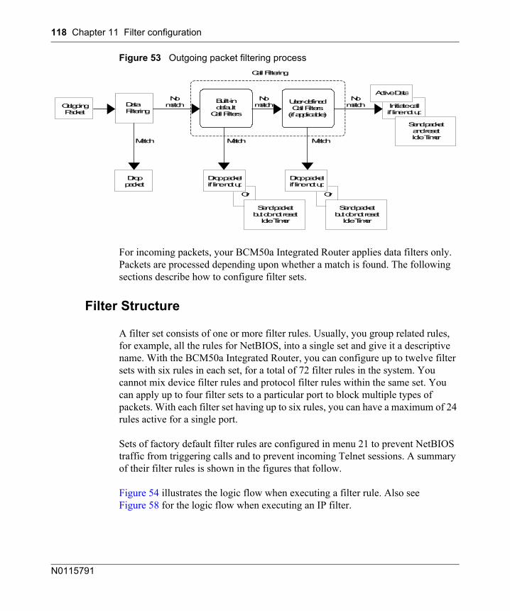
118 Chapter 11 Filter configuration
N0115791
Figure 53 Outgoing packet filtering process
For incoming packets, your BCM50a Integrated Router applies data filters only. Packets are processed depending upon whether a match is found. The following sections describe how to configure filter sets.
Filter Structure
A filter set consists of one or more filter rules. Usually, you group related rules, for example, all the rules for NetBIOS, into a single set and give it a descriptive name. With the BCM50a Integrated Router, you can configure up to twelve filter sets with six rules in each set, for a total of 72 filter rules in the system. You cannot mix device filter rules and protocol filter rules within the same set. You can apply up to four filter sets to a particular port to block multiple types of packets. With each filter set having up to six rules, you can have a maximum of 24 rules active for a single port.
Sets of factory default filter rules are configured in menu 21 to prevent NetBIOS traffic from triggering calls and to prevent incoming Telnet sessions. A summary of their filter rules is shown in the figures that follow.
Figure 54 illustrates the logic flow when executing a filter rule. Also see Figure 58 for the logic flow when executing an IP filter.
Data Filtering Outgoing
Packet
Droppacket
Built-indefault
Call Filters
User-definedCall Filters
(if applicable)Initiate callif line not up
Active Data
Send packetand resetIdle Timer
Or Or
Drop packetif line not up
Drop packetif line not up
Send packetbut do not reset
Idle Timer
Send packetbut do not reset
Idle Timer
Match MatchMatch
Nomatch
Nomatch
Nomatch
Call Filtering
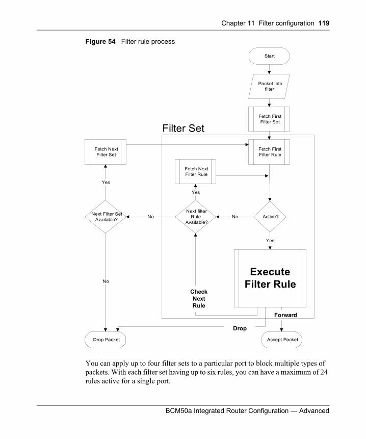
Chapter 11 Filter configuration 119
BCM50a Integrated Router Configuration — Advanced
Figure 54 Filter rule process
You can apply up to four filter sets to a particular port to block multiple types of packets. With each filter set having up to six rules, you can have a maximum of 24 rules active for a single port.
Start
Fetch FirstFilter Set
Fetch FirstFilter Rule
Active?
ExecuteFilter Rule
Fetch NextFilter Rule
Next filterRule
Available?
Fetch NextFilter Set
Next Filter SetAvailable?
Accept PacketDrop Packet
Yes
No
Yes
No
Yes
Packet intofilter
Filter Set
Forward
Drop
No
CheckNextRule
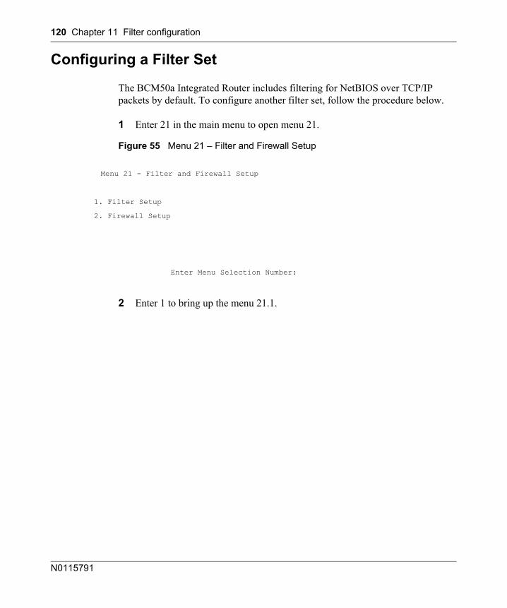
120 Chapter 11 Filter configuration
N0115791
Configuring a Filter Set
The BCM50a Integrated Router includes filtering for NetBIOS over TCP/IP packets by default. To configure another filter set, follow the procedure below.
1 Enter 21 in the main menu to open menu 21.
Figure 55 Menu 21 – Filter and Firewall Setup
2 Enter 1 to bring up the menu 21.1.
Menu 21 - Filter and Firewall Setup
1. Filter Setup
2. Firewall Setup
Enter Menu Selection Number:
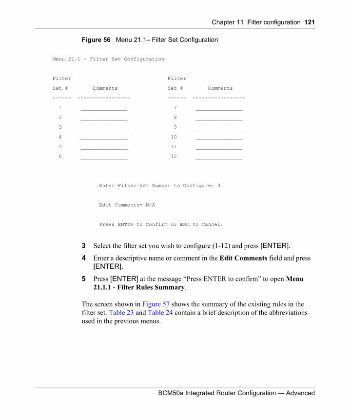
Chapter 11 Filter configuration 121
BCM50a Integrated Router Configuration — Advanced
Figure 56 Menu 21.1– Filter Set Configuration
3 Select the filter set you wish to configure (1-12) and press [ENTER].4 Enter a descriptive name or comment in the Edit Comments field and press
[ENTER].
5 Press [ENTER] at the message “Press ENTER to confirm” to open Menu 21.1.1 - Filter Rules Summary.
The screen shown in Figure 57 shows the summary of the existing rules in the filter set. Table 23 and Table 24 contain a brief description of the abbreviations used in the previous menus.
Menu 21.1 - Filter Set Configuration
Filter Filter
Set # Comments Set # Comments
------ ----------------- ------ -----------------
1 _______________ 7 _______________
2 _______________ 8 _______________
3 _______________ 9 _______________
4 _______________ 10 _______________
5 _______________ 11 _______________
6 _______________ 12 _______________
Enter Filter Set Number to Configure= 0
Edit Comments= N/A
Press ENTER to Confirm or ESC to Cancel:
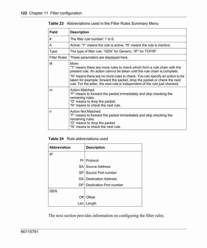
122 Chapter 11 Filter configuration
N0115791
The next section provides information on configuring the filter rules.
Table 23 Abbreviations used in the Filter Rules Summary Menu
Field Description
# The filter rule number: 1 to 6.
A Active: “Y” means the rule is active. “N” means the rule is inactive.
Type The type of filter rule: “GEN” for Generic, “IP” for TCP/IP.
Filter Rules These parameters are displayed here.
M More:“Y” means there are more rules to check which form a rule chain with the present rule. An action cannot be taken until the rule chain is complete.“N” means there are no more rules to check. You can specify an action to be taken for example, forward the packet, drop the packet or check the next rule. For the latter, the next rule is independent of the rule just checked.
m Action Matched:“F” means to forward the packet immediately and skip checking the remaining rules.“D” means to drop the packet.“N“ means to check the next rule.
n Action Not Matched:“F” means to forward the packet immediately and skip checking the remaining rules.“D” means to drop the packet.“N” means to check the next rule.
Table 24 Rule abbreviations used
Abbreviation Description
IP
Pr Protocol
SA Source Address
SP Source Port number
DA Destination Address
DP Destination Port number
GEN
Off Offset
Len Length
Chapter 11 Filter configuration 123
BCM50a Integrated Router Configuration — Advanced
Configuring a Filter Rule
To configure a filter rule, type its number in Menu 21.1.1 - Filter Rules Summary and press [ENTER] to open menu 21.1.1.1 for the rule.
To speed up filtering, all rules in a filter set must be of the same class, for example, protocol filters or generic filters. The class of a filter set is determined by the first rule that you create. When applying the filter sets to a port, separate menu fields are provided for protocol and device filter sets. If you include a protocol filter set in a device filter field or vice versa, the BCM50a Integrated Router warns you and prevents you from saving.
Configuring a TCP/IP Filter Rule
This section shows you how to configure a TCP/IP filter rule. Using TCP/IP rules, you can base the rule on the fields in the IP and the upper layer protocol, for example, UDP and TCP headers.
To configure TCP/IP rules, select TCP/IP Filter Rule from the Filter Type field and press [ENTER] to open Menu 21.1.1.1 - TCP/IP Filter Rule, as shown in Figure 57.
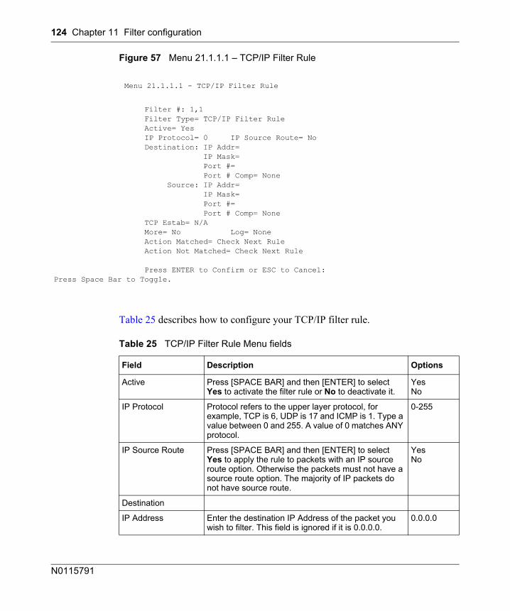
124 Chapter 11 Filter configuration
N0115791
Figure 57 Menu 21.1.1.1 – TCP/IP Filter Rule
Table 25 describes how to configure your TCP/IP filter rule.
Menu 21.1.1.1 - TCP/IP Filter Rule
Filter #: 1,1 Filter Type= TCP/IP Filter Rule Active= Yes IP Protocol= 0 IP Source Route= No Destination: IP Addr= IP Mask= Port #= Port # Comp= None Source: IP Addr= IP Mask= Port #= Port # Comp= None TCP Estab= N/A More= No Log= None Action Matched= Check Next Rule Action Not Matched= Check Next Rule
Press ENTER to Confirm or ESC to Cancel:Press Space Bar to Toggle.
Table 25 TCP/IP Filter Rule Menu fields
Field Description Options
Active Press [SPACE BAR] and then [ENTER] to select Yes to activate the filter rule or No to deactivate it.
YesNo
IP Protocol Protocol refers to the upper layer protocol, for example, TCP is 6, UDP is 17 and ICMP is 1. Type a value between 0 and 255. A value of 0 matches ANY protocol.
0-255
IP Source Route Press [SPACE BAR] and then [ENTER] to select Yes to apply the rule to packets with an IP source route option. Otherwise the packets must not have a source route option. The majority of IP packets do not have source route.
YesNo
Destination
IP Address Enter the destination IP Address of the packet you wish to filter. This field is ignored if it is 0.0.0.0.
0.0.0.0
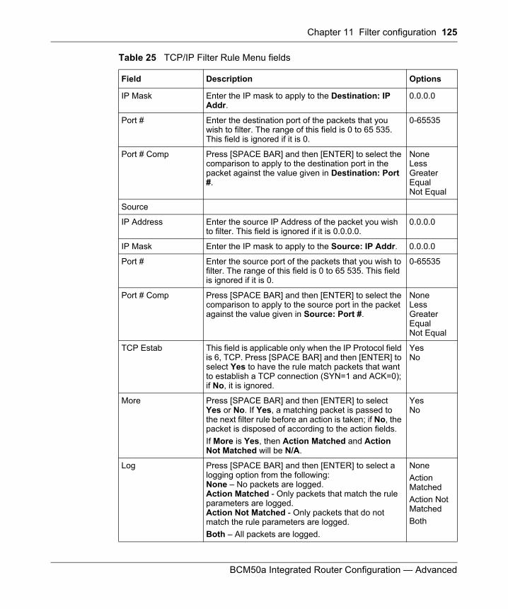
Chapter 11 Filter configuration 125
BCM50a Integrated Router Configuration — Advanced
IP Mask Enter the IP mask to apply to the Destination: IP Addr.
0.0.0.0
Port # Enter the destination port of the packets that you wish to filter. The range of this field is 0 to 65 535. This field is ignored if it is 0.
0-65535
Port # Comp Press [SPACE BAR] and then [ENTER] to select the comparison to apply to the destination port in the packet against the value given in Destination: Port #.
NoneLessGreaterEqualNot Equal
Source
IP Address Enter the source IP Address of the packet you wish to filter. This field is ignored if it is 0.0.0.0.
0.0.0.0
IP Mask Enter the IP mask to apply to the Source: IP Addr. 0.0.0.0
Port # Enter the source port of the packets that you wish to filter. The range of this field is 0 to 65 535. This field is ignored if it is 0.
0-65535
Port # Comp Press [SPACE BAR] and then [ENTER] to select the comparison to apply to the source port in the packet against the value given in Source: Port #.
NoneLessGreaterEqualNot Equal
TCP Estab This field is applicable only when the IP Protocol field is 6, TCP. Press [SPACE BAR] and then [ENTER] to select Yes to have the rule match packets that want to establish a TCP connection (SYN=1 and ACK=0); if No, it is ignored.
YesNo
More Press [SPACE BAR] and then [ENTER] to select Yes or No. If Yes, a matching packet is passed to the next filter rule before an action is taken; if No, the packet is disposed of according to the action fields.If More is Yes, then Action Matched and Action Not Matched will be N/A.
YesNo
Log Press [SPACE BAR] and then [ENTER] to select a logging option from the following:None – No packets are logged.Action Matched - Only packets that match the rule parameters are logged.Action Not Matched - Only packets that do not match the rule parameters are logged.Both – All packets are logged.
NoneAction MatchedAction Not MatchedBoth
Table 25 TCP/IP Filter Rule Menu fields
Field Description Options
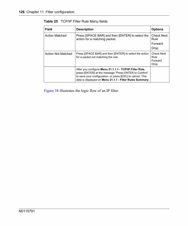
126 Chapter 11 Filter configuration
N0115791
Figure 58 illustrates the logic flow of an IP filter.
Action Matched Press [SPACE BAR] and then [ENTER] to select the action for a matching packet.
Check Next RuleForwardDrop
Action Not Matched Press [SPACE BAR] and then [ENTER] to select the action for a packet not matching the rule.
Check Next RuleForwardDrop
After you configure Menu 21.1.1.1 - TCP/IP Filter Rule, press [ENTER] at the message “Press ENTER to Confirm” to save your configuration, or press [ESC] to cancel. This data is displayed on Menu 21.1.1 - Filter Rules Summary.
Table 25 TCP/IP Filter Rule Menu fields
Field Description Options
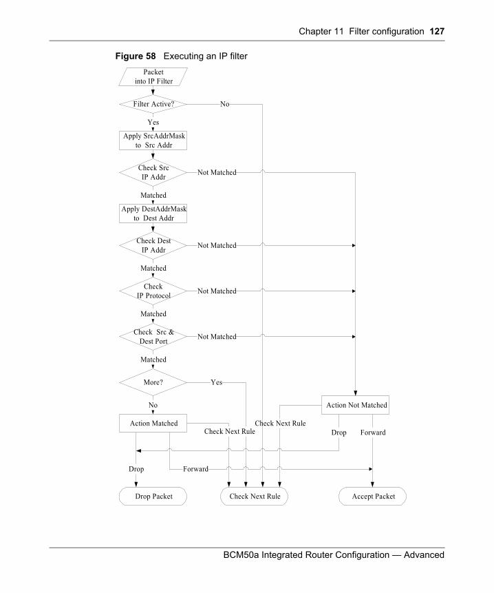
Chapter 11 Filter configuration 127
BCM50a Integrated Router Configuration — Advanced
Figure 58 Executing an IP filter
Packetinto IP Filter
Matched
Matched
Yes
Action Matched
Action Not Matched
More?
No
Filter Active?
CheckIP Protocol
Drop
Drop Packet Accept Packet
Drop ForwardCheck Next Rule
Check Next Rule
Check Next Rule
Forward
Not Matched
Yes
No
Check SrcIP Addr
Apply SrcAddrMaskto Src Addr
Matched
Check DestIP Addr
Apply DestAddrMaskto Dest Addr
Not Matched
Not Matched
Check Src &Dest Port
Matched
Not Matched
128 Chapter 11 Filter configuration
N0115791
Configuring a Generic Filter Rule
This section shows you how to configure a generic filter rule. With generic rules you can filter non-IP packets. For IP packets, it is generally easier to use the IP rules directly.
For generic rules, the BCM50a Integrated Router treats a packet as a byte stream as opposed to an IP or IPX packet. You specify the portion of the packet to check with the Offset (from 0) and the Length fields, both in bytes. The BCM50a Integrated Router applies the Mask (using the bit-wise-AND action) to the data portion before comparing the result against the Value to determine a match. The Mask and Value are specified in hexadecimal numbers. Note that it takes two hexadecimal digits to represent a byte, so if the length is 4, the value in either field will take 8 digits, for example, FFFFFFFF.
To configure a generic rule, select Generic Filter Rule in the Filter Type field in menu 21.1.1.1 and press [ENTER] to open Generic Filter Rule, as shown in Figure 59.
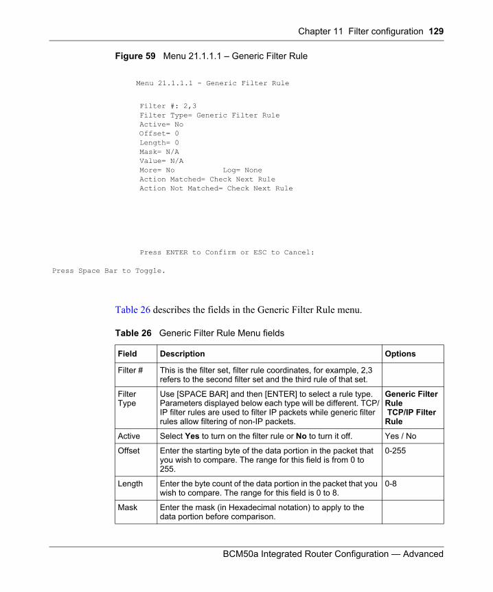
Chapter 11 Filter configuration 129
BCM50a Integrated Router Configuration — Advanced
Figure 59 Menu 21.1.1.1 – Generic Filter Rule
Table 26 describes the fields in the Generic Filter Rule menu.
Menu 21.1.1.1 - Generic Filter Rule
Filter #: 2,3 Filter Type= Generic Filter Rule Active= No Offset= 0 Length= 0 Mask= N/A Value= N/A More= No Log= None Action Matched= Check Next Rule Action Not Matched= Check Next Rule
Press ENTER to Confirm or ESC to Cancel:
Press Space Bar to Toggle.
Table 26 Generic Filter Rule Menu fields
Field Description Options
Filter # This is the filter set, filter rule coordinates, for example, 2,3 refers to the second filter set and the third rule of that set.
Filter Type
Use [SPACE BAR] and then [ENTER] to select a rule type. Parameters displayed below each type will be different. TCP/IP filter rules are used to filter IP packets while generic filter rules allow filtering of non-IP packets.
Generic Filter Rule TCP/IP Filter Rule
Active Select Yes to turn on the filter rule or No to turn it off. Yes / No
Offset Enter the starting byte of the data portion in the packet that you wish to compare. The range for this field is from 0 to 255.
0-255
Length Enter the byte count of the data portion in the packet that you wish to compare. The range for this field is 0 to 8.
0-8
Mask Enter the mask (in Hexadecimal notation) to apply to the data portion before comparison.
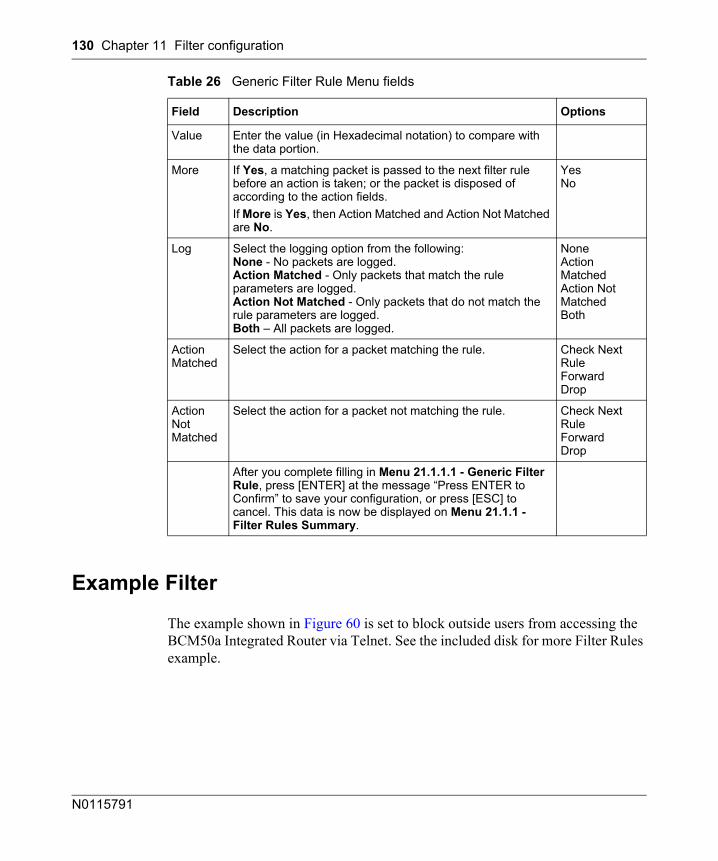
130 Chapter 11 Filter configuration
N0115791
Example Filter
The example shown in Figure 60 is set to block outside users from accessing the BCM50a Integrated Router via Telnet. See the included disk for more Filter Rules example.
Value Enter the value (in Hexadecimal notation) to compare with the data portion.
More If Yes, a matching packet is passed to the next filter rule before an action is taken; or the packet is disposed of according to the action fields.If More is Yes, then Action Matched and Action Not Matched are No.
YesNo
Log Select the logging option from the following:None - No packets are logged.Action Matched - Only packets that match the rule parameters are logged.Action Not Matched - Only packets that do not match the rule parameters are logged.Both – All packets are logged.
NoneAction MatchedAction Not MatchedBoth
Action Matched
Select the action for a packet matching the rule. Check Next RuleForwardDrop
Action Not Matched
Select the action for a packet not matching the rule. Check Next RuleForwardDrop
After you complete filling in Menu 21.1.1.1 - Generic Filter Rule, press [ENTER] at the message “Press ENTER to Confirm” to save your configuration, or press [ESC] to cancel. This data is now be displayed on Menu 21.1.1 - Filter Rules Summary.
Table 26 Generic Filter Rule Menu fields
Field Description Options
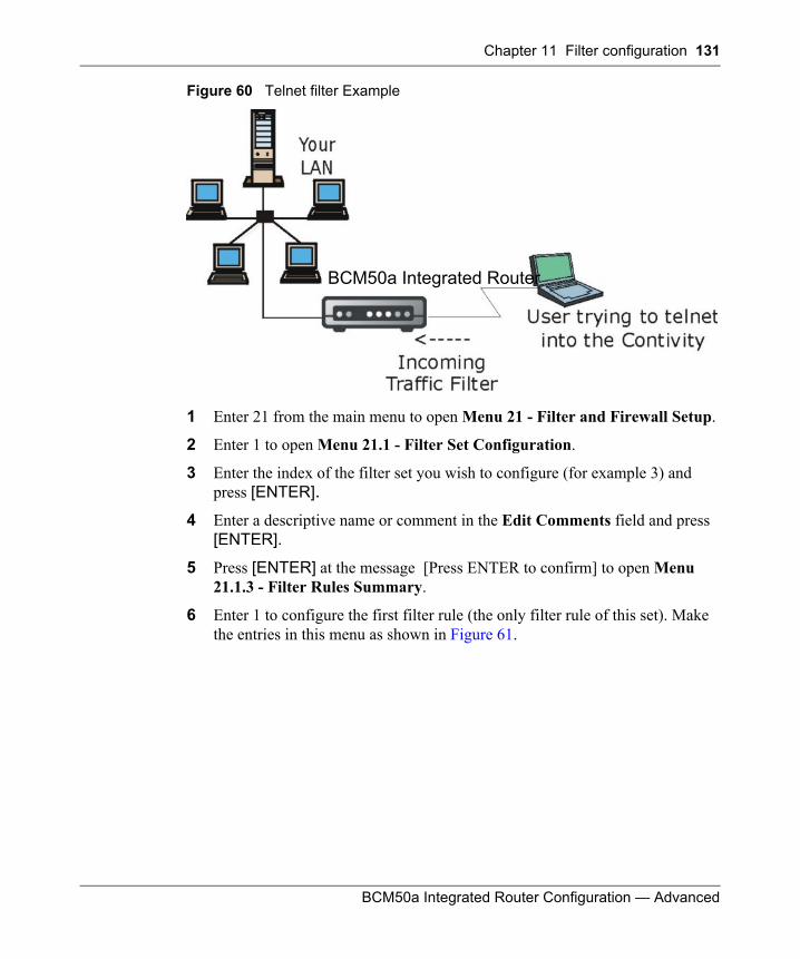
Chapter 11 Filter configuration 131
BCM50a Integrated Router Configuration — Advanced
Figure 60 Telnet filter Example
1 Enter 21 from the main menu to open Menu 21 - Filter and Firewall Setup.
2 Enter 1 to open Menu 21.1 - Filter Set Configuration.
3 Enter the index of the filter set you wish to configure (for example 3) and press [ENTER].
4 Enter a descriptive name or comment in the Edit Comments field and press [ENTER].
5 Press [ENTER] at the message [Press ENTER to confirm] to open Menu 21.1.3 - Filter Rules Summary.
6 Enter 1 to configure the first filter rule (the only filter rule of this set). Make the entries in this menu as shown in Figure 61.
BCM50a Integrated Router
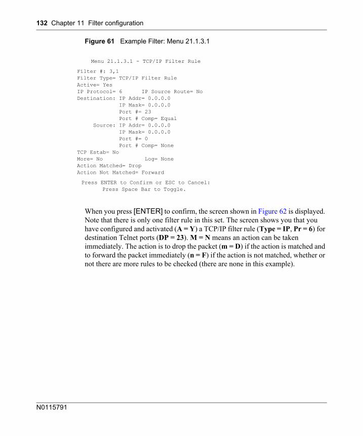
132 Chapter 11 Filter configuration
N0115791
Figure 61 Example Filter: Menu 21.1.3.1
When you press [ENTER] to confirm, the screen shown in Figure 62 is displayed. Note that there is only one filter rule in this set. The screen shows you that you have configured and activated (A = Y) a TCP/IP filter rule (Type = IP, Pr = 6) for destination Telnet ports (DP = 23). M = N means an action can be taken immediately. The action is to drop the packet (m = D) if the action is matched and to forward the packet immediately (n = F) if the action is not matched, whether or not there are more rules to be checked (there are none in this example).
Menu 21.1.3.1 - TCP/IP Filter Rule
Filter #: 3,1 Filter Type= TCP/IP Filter Rule Active= Yes IP Protocol= 6 IP Source Route= No Destination: IP Addr= 0.0.0.0 IP Mask= 0.0.0.0 Port #= 23 Port # Comp= Equal Source: IP Addr= 0.0.0.0 IP Mask= 0.0.0.0 Port #= 0 Port # Comp= None TCP Estab= No More= No Log= None Action Matched= Drop Action Not Matched= Forward
Press ENTER to Confirm or ESC to Cancel:Press Space Bar to Toggle.
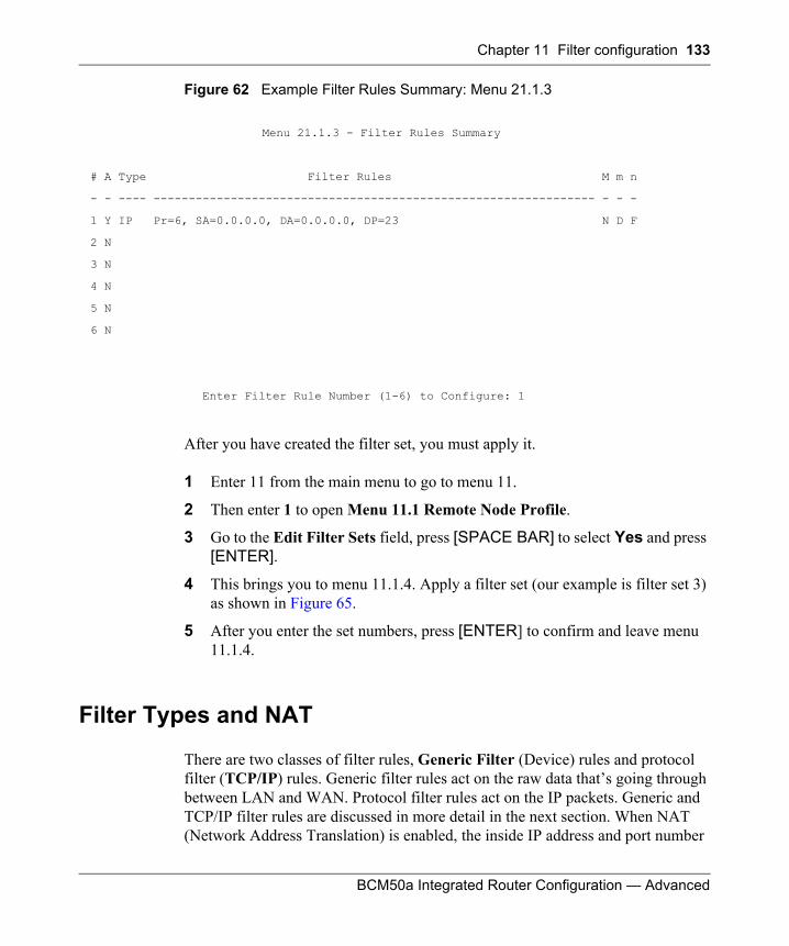
Chapter 11 Filter configuration 133
BCM50a Integrated Router Configuration — Advanced
Figure 62 Example Filter Rules Summary: Menu 21.1.3
After you have created the filter set, you must apply it.
1 Enter 11 from the main menu to go to menu 11.
2 Then enter 1 to open Menu 11.1 Remote Node Profile.
3 Go to the Edit Filter Sets field, press [SPACE BAR] to select Yes and press [ENTER].
4 This brings you to menu 11.1.4. Apply a filter set (our example is filter set 3) as shown in Figure 65.
5 After you enter the set numbers, press [ENTER] to confirm and leave menu 11.1.4.
Filter Types and NAT
There are two classes of filter rules, Generic Filter (Device) rules and protocol filter (TCP/IP) rules. Generic filter rules act on the raw data that’s going through between LAN and WAN. Protocol filter rules act on the IP packets. Generic and TCP/IP filter rules are discussed in more detail in the next section. When NAT (Network Address Translation) is enabled, the inside IP address and port number
Menu 21.1.3 - Filter Rules Summary
# A Type Filter Rules M m n
- - ---- --------------------------------------------------------------- - - -
1 Y IP Pr=6, SA=0.0.0.0, DA=0.0.0.0, DP=23 N D F
2 N
3 N
4 N
5 N
6 N
Enter Filter Rule Number (1-6) to Configure: 1
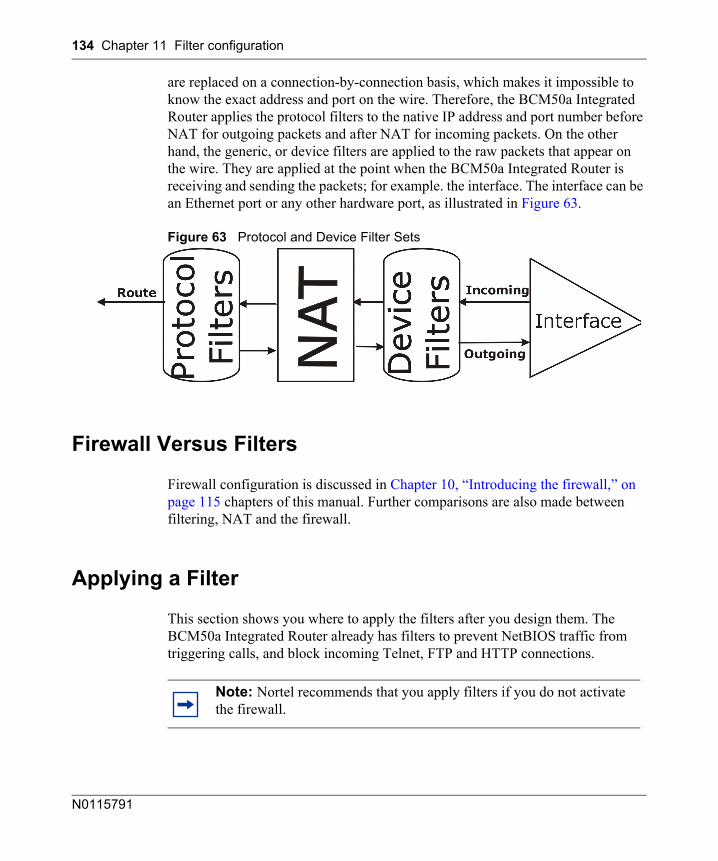
134 Chapter 11 Filter configuration
N0115791
are replaced on a connection-by-connection basis, which makes it impossible to know the exact address and port on the wire. Therefore, the BCM50a Integrated Router applies the protocol filters to the native IP address and port number before NAT for outgoing packets and after NAT for incoming packets. On the other hand, the generic, or device filters are applied to the raw packets that appear on the wire. They are applied at the point when the BCM50a Integrated Router is receiving and sending the packets; for example. the interface. The interface can be an Ethernet port or any other hardware port, as illustrated in Figure 63.
Figure 63 Protocol and Device Filter Sets
Firewall Versus Filters
Firewall configuration is discussed in Chapter 10, “Introducing the firewall,” on page 115 chapters of this manual. Further comparisons are also made between filtering, NAT and the firewall.
Applying a Filter
This section shows you where to apply the filters after you design them. The BCM50a Integrated Router already has filters to prevent NetBIOS traffic from triggering calls, and block incoming Telnet, FTP and HTTP connections.
Note: Nortel recommends that you apply filters if you do not activate the firewall.
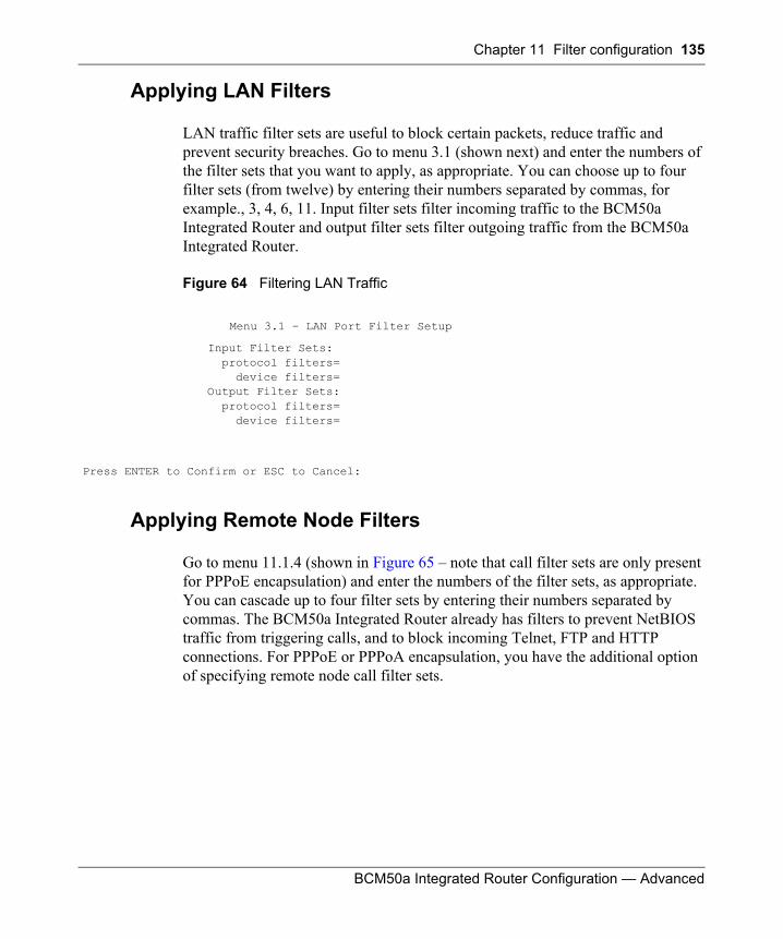
Chapter 11 Filter configuration 135
BCM50a Integrated Router Configuration — Advanced
Applying LAN Filters
LAN traffic filter sets are useful to block certain packets, reduce traffic and prevent security breaches. Go to menu 3.1 (shown next) and enter the numbers of the filter sets that you want to apply, as appropriate. You can choose up to four filter sets (from twelve) by entering their numbers separated by commas, for example., 3, 4, 6, 11. Input filter sets filter incoming traffic to the BCM50a Integrated Router and output filter sets filter outgoing traffic from the BCM50a Integrated Router.
Figure 64 Filtering LAN Traffic
Applying Remote Node Filters
Go to menu 11.1.4 (shown in Figure 65 – note that call filter sets are only present for PPPoE encapsulation) and enter the numbers of the filter sets, as appropriate. You can cascade up to four filter sets by entering their numbers separated by commas. The BCM50a Integrated Router already has filters to prevent NetBIOS traffic from triggering calls, and to block incoming Telnet, FTP and HTTP connections. For PPPoE or PPPoA encapsulation, you have the additional option of specifying remote node call filter sets.
Menu 3.1 – LAN Port Filter Setup
Input Filter Sets: protocol filters= device filters= Output Filter Sets: protocol filters= device filters=
Press ENTER to Confirm or ESC to Cancel:
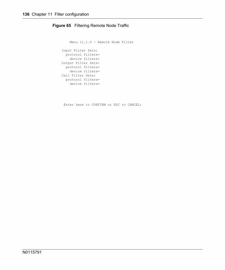
136 Chapter 11 Filter configuration
N0115791
Figure 65 Filtering Remote Node Traffic
Menu 11.1.4 - Remote Node Filter
Input Filter Sets: protocol filters= device filters= Output Filter Sets: protocol filters= device filters= Call Filter Sets: protocol filters= device filters=
Enter here to CONFIRM or ESC to CANCEL:
137
BCM50a Integrated Router Configuration — Advanced
Chapter 12SNMP Configuration
This chapter explains SNMP configuration menu 22.
SNMP Configuration
To configure SNMP, enter 22 from the main menu to display Menu 22 - SNMP Configuration as shown next. The community for Get, Set and Trap fields is SNMP terminology for password.
Note: SNMP is only available if TCP/IP is configured.
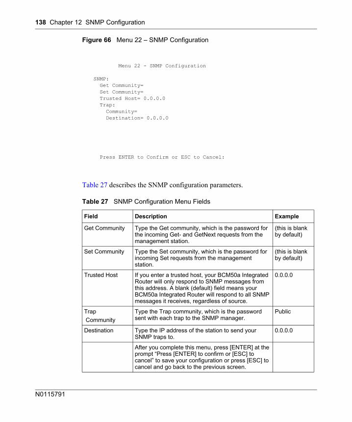
138 Chapter 12 SNMP Configuration
N0115791
Figure 66 Menu 22 – SNMP Configuration
Table 27 describes the SNMP configuration parameters.
Menu 22 - SNMP Configuration
SNMP: Get Community= Set Community= Trusted Host= 0.0.0.0 Trap: Community= Destination= 0.0.0.0
Press ENTER to Confirm or ESC to Cancel:
Table 27 SNMP Configuration Menu Fields
Field Description Example
Get Community Type the Get community, which is the password for the incoming Get- and GetNext requests from the management station.
(this is blank by default)
Set Community Type the Set community, which is the password for incoming Set requests from the management station.
(this is blank by default)
Trusted Host If you enter a trusted host, your BCM50a Integrated Router will only respond to SNMP messages from this address. A blank (default) field means your BCM50a Integrated Router will respond to all SNMP messages it receives, regardless of source.
0.0.0.0
Trap Community
Type the Trap community, which is the password sent with each trap to the SNMP manager.
Public
Destination Type the IP address of the station to send your SNMP traps to.
0.0.0.0
After you complete this menu, press [ENTER] at the prompt “Press [ENTER] to confirm or [ESC] to cancel” to save your configuration or press [ESC] to cancel and go back to the previous screen.
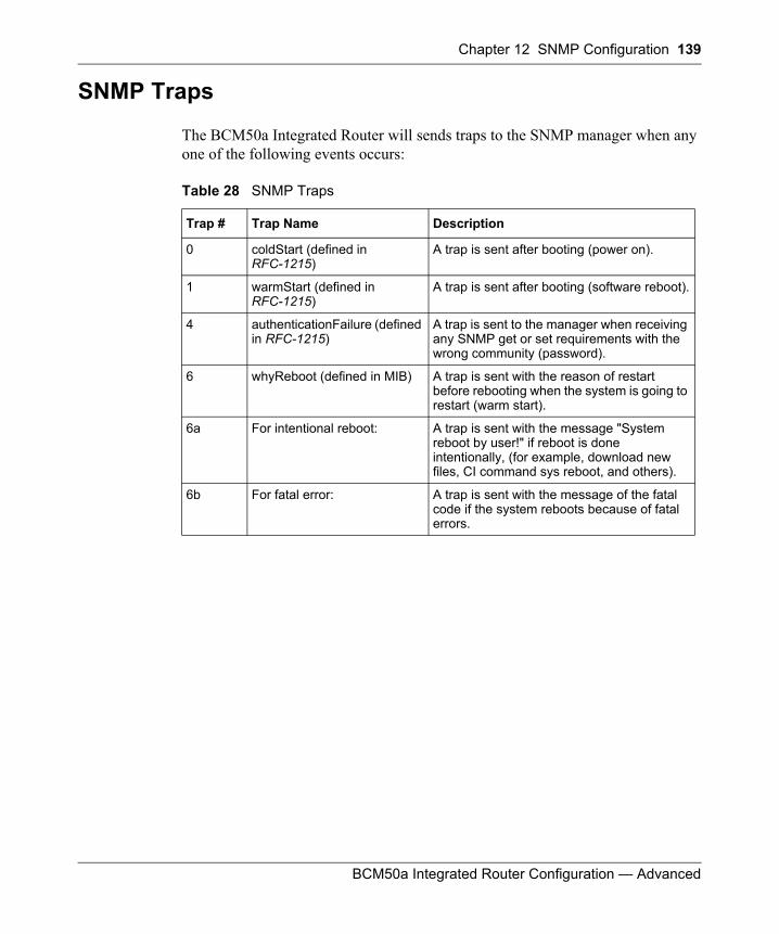
Chapter 12 SNMP Configuration 139
BCM50a Integrated Router Configuration — Advanced
SNMP Traps
The BCM50a Integrated Router will sends traps to the SNMP manager when any one of the following events occurs:
Table 28 SNMP Traps
Trap # Trap Name Description
0 coldStart (defined in RFC-1215)
A trap is sent after booting (power on).
1 warmStart (defined in RFC-1215)
A trap is sent after booting (software reboot).
4 authenticationFailure (defined in RFC-1215)
A trap is sent to the manager when receiving any SNMP get or set requirements with the wrong community (password).
6 whyReboot (defined in MIB) A trap is sent with the reason of restart before rebooting when the system is going to restart (warm start).
6a For intentional reboot: A trap is sent with the message "System reboot by user!" if reboot is done intentionally, (for example, download new files, CI command sys reboot, and others).
6b For fatal error: A trap is sent with the message of the fatal code if the system reboots because of fatal errors.

140 Chapter 12 SNMP Configuration
N0115791
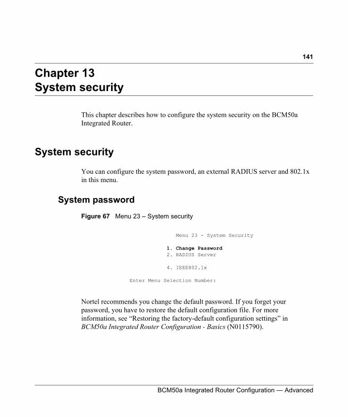
141
BCM50a Integrated Router Configuration — Advanced
Chapter 13System security
This chapter describes how to configure the system security on the BCM50a Integrated Router.
System security
You can configure the system password, an external RADIUS server and 802.1x in this menu.
System password
Figure 67 Menu 23 – System security
Nortel recommends you change the default password. If you forget your password, you have to restore the default configuration file. For more information, see “Restoring the factory-default configuration settings” in BCM50a Integrated Router Configuration - Basics (N0115790).
Menu 23 - System Security
1. Change Password 2. RADIUS Server
4. IEEE802.1x
Enter Menu Selection Number:
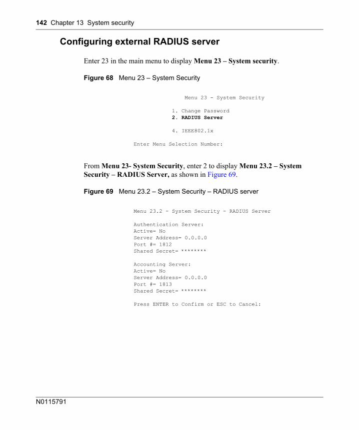
142 Chapter 13 System security
N0115791
Configuring external RADIUS server
Enter 23 in the main menu to display Menu 23 – System security.
Figure 68 Menu 23 – System Security
From Menu 23- System Security, enter 2 to display Menu 23.2 – System Security – RADIUS Server, as shown in Figure 69.
Figure 69 Menu 23.2 – System Security – RADIUS server
Menu 23 - System Security
1. Change Password 2. RADIUS Server
4. IEEE802.1x
Enter Menu Selection Number:
Menu 23.2 - System Security - RADIUS Server
Authentication Server:Active= NoServer Address= 0.0.0.0Port #= 1812Shared Secret= ********
Accounting Server:Active= NoServer Address= 0.0.0.0Port #= 1813Shared Secret= ********
Press ENTER to Confirm or ESC to Cancel:
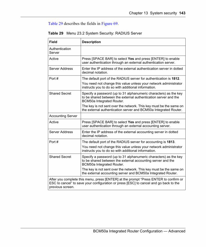
Chapter 13 System security 143
BCM50a Integrated Router Configuration — Advanced
Table 29 describes the fields in Figure 69.
Table 29 Menu 23.2 System Security: RADIUS Server
Field Description
Authentication Server
Active Press [SPACE BAR] to select Yes and press [ENTER] to enable user authentication through an external authentication server.
Server Address Enter the IP address of the external authentication server in dotted decimal notation.
Port # The default port of the RADIUS server for authentication is 1812. You need not change this value unless your network administrator instructs you to do so with additional information.
Shared Secret Specify a password (up to 31 alphanumeric characters) as the key to be shared between the external authentication server and the BCM50a Integrated Router. The key is not sent over the network. This key must be the same on the external authentication server and BCM50a Integrated Router.
Accounting Server
Active Press [SPACE BAR] to select Yes and press [ENTER] to enable user authentication through an external accounting server.
Server Address Enter the IP address of the external accounting server in dotted decimal notation.
Port # The default port of the RADIUS server for accounting is 1813. You need not change this value unless your network administrator instructs you to do so with additional information.
Shared Secret Specify a password (up to 31 alphanumeric characters) as the key to be shared between the external accounting server and the BCM50a Integrated Router.The key is not sent over the network. This key must be the same on the external accounting server and BCM50a Integrated Router.
After you complete this menu, press [ENTER] at the prompt “Press ENTER to confirm or ESC to cancel” to save your configuration or press [ESC] to cancel and go back to the previous screen.

144 Chapter 13 System security
N0115791

145
BCM50a Integrated Router Configuration — Advanced
Chapter 14System information and diagnosis
This chapter covers SMT menus 24.1 to 24.4.
Introduction to System Status
This chapter covers the diagnostic tools that help you to maintain your BCM50a Integrated Router. These tools include updates on system status, port status and log and trace capabilities.
Select menu 24 in the main menu to open Menu 24 - System Maintenance, as shown in Figure 70.
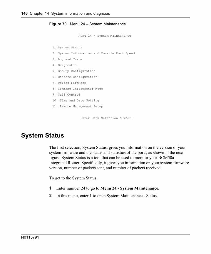
146 Chapter 14 System information and diagnosis
N0115791
Figure 70 Menu 24 – System Maintenance
System Status
The first selection, System Status, gives you information on the version of your system firmware and the status and statistics of the ports, as shown in the next figure. System Status is a tool that can be used to monitor your BCM50a Integrated Router. Specifically, it gives you information on your system firmware version, number of packets sent, and number of packets received.
To get to the System Status:
1 Enter number 24 to go to Menu 24 - System Maintenance.
2 In this menu, enter 1 to open System Maintenance - Status.
Menu 24 - System Maintenance
1. System Status
2. System Information and Console Port Speed
3. Log and Trace
4. Diagnostic
5. Backup Configuration
6. Restore Configuration
7. Upload Firmware
8. Command Interpreter Mode
9. Call Control
10. Time and Date Setting
11. Remote Management Setup
Enter Menu Selection Number:
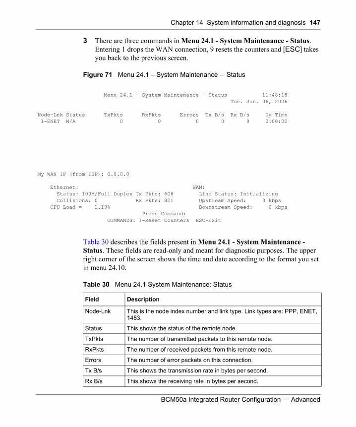
Chapter 14 System information and diagnosis 147
BCM50a Integrated Router Configuration — Advanced
3 There are three commands in Menu 24.1 - System Maintenance - Status. Entering 1 drops the WAN connection, 9 resets the counters and [ESC] takes you back to the previous screen.
Table 30 describes the fields present in Menu 24.1 - System Maintenance - Status. These fields are read-only and meant for diagnostic purposes. The upper right corner of the screen shows the time and date according to the format you set in menu 24.10.
Figure 71 Menu 24.1 – System Maintenance – Status
Menu 24.1 - System Maintenance - Status 11:48:18 Tue. Jun. 06, 2006
Node-Lnk Status TxPkts RxPkts Errors Tx B/s Rx B/s Up Time 1-ENET N/A 0 0 0 0 0 0:00:00
My WAN IP (from ISP): 0.0.0.0
Ethernet: WAN: Status: 100M/Full Duplex Tx Pkts: 608 Line Status: Initializing Collisions: 0 Rx Pkts: 821 Upstream Speed: 0 kbps CPU Load = 1.19% Downstream Speed: 0 kbps Press Command: COMMANDS: 1-Reset Counters ESC-Exit
Table 30 Menu 24.1 System Maintenance: Status
Field Description
Node-Lnk This is the node index number and link type. Link types are: PPP, ENET, 1483.
Status This shows the status of the remote node.
TxPkts The number of transmitted packets to this remote node.
RxPkts The number of received packets from this remote node.
Errors The number of error packets on this connection.
Tx B/s This shows the transmission rate in bytes per second.
Rx B/s This shows the receiving rate in bytes per second.
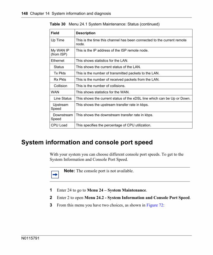
148 Chapter 14 System information and diagnosis
N0115791
System information and console port speed
With your system you can choose different console port speeds. To get to the System Information and Console Port Speed.
1 Enter 24 to go to Menu 24 – System Maintenance.
2 Enter 2 to open Menu 24.2 - System Information and Console Port Speed.
3 From this menu you have two choices, as shown in Figure 72:
Up Time This is the time this channel has been connected to the current remote node.
My WAN IP (from ISP)
This is the IP address of the ISP remote node.
Ethernet This shows statistics for the LAN.
Status This shows the current status of the LAN.
Tx Pkts This is the number of transmitted packets to the LAN.
Rx Pkts This is the number of received packets from the LAN.
Collision This is the number of collisions.
WAN This shows statistics for the WAN.
Line Status This shows the current status of the xDSL line which can be Up or Down.
Upstream Speed
This shows the upstream transfer rate in kbps.
Downstream Speed
This shows the downstream transfer rate in kbps.
CPU Load This specifies the percentage of CPU utilization.
Note: The console port is not available.
Table 30 Menu 24.1 System Maintenance: Status (continued)
Field Description
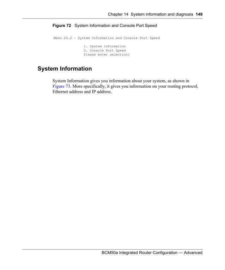
Chapter 14 System information and diagnosis 149
BCM50a Integrated Router Configuration — Advanced
Figure 72 System Information and Console Port Speed
System Information
System Information gives you information about your system, as shown in Figure 73. More specifically, it gives you information on your routing protocol, Ethernet address and IP address.
Menu 24.2 - System Information and Console Port Speed
1. System Information2. Console Port Speed Please enter selection:
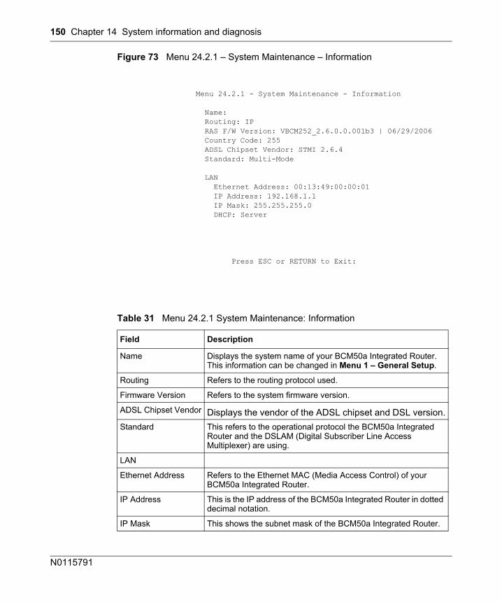
150 Chapter 14 System information and diagnosis
N0115791
Figure 73 Menu 24.2.1 – System Maintenance – Information
Menu 24.2.1 - System Maintenance - Information
Name: Routing: IP RAS F/W Version: VBCM252_2.6.0.0.001b3 | 06/29/2006 Country Code: 255 ADSL Chipset Vendor: STMI 2.6.4 Standard: Multi-Mode
LAN Ethernet Address: 00:13:49:00:00:01 IP Address: 192.168.1.1 IP Mask: 255.255.255.0 DHCP: Server
Press ESC or RETURN to Exit:
Table 31 Menu 24.2.1 System Maintenance: Information
Field Description
Name Displays the system name of your BCM50a Integrated Router. This information can be changed in Menu 1 – General Setup.
Routing Refers to the routing protocol used.
Firmware Version Refers to the system firmware version.
ADSL Chipset Vendor Displays the vendor of the ADSL chipset and DSL version.Standard This refers to the operational protocol the BCM50a Integrated
Router and the DSLAM (Digital Subscriber Line Access Multiplexer) are using.
LAN
Ethernet Address Refers to the Ethernet MAC (Media Access Control) of your BCM50a Integrated Router.
IP Address This is the IP address of the BCM50a Integrated Router in dotted decimal notation.
IP Mask This shows the subnet mask of the BCM50a Integrated Router.
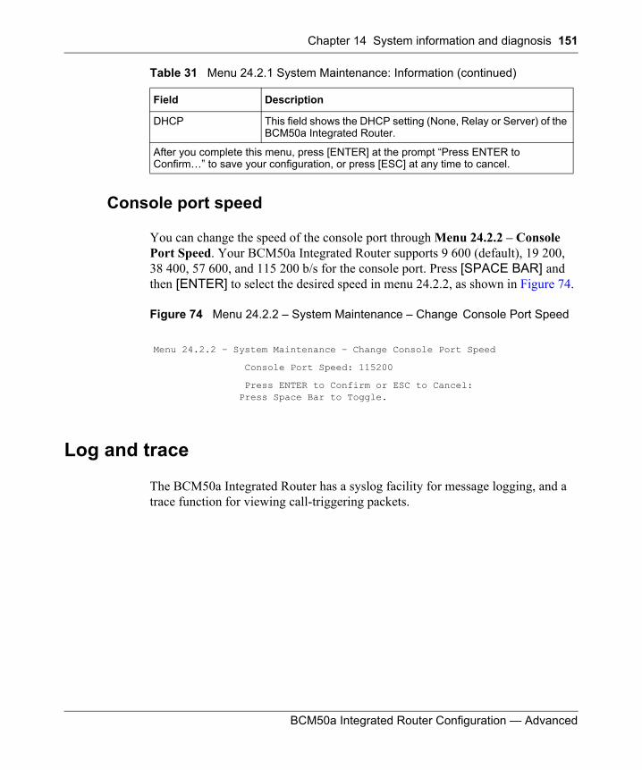
Chapter 14 System information and diagnosis 151
BCM50a Integrated Router Configuration — Advanced
Console port speed
You can change the speed of the console port through Menu 24.2.2 – Console Port Speed. Your BCM50a Integrated Router supports 9 600 (default), 19 200, 38 400, 57 600, and 115 200 b/s for the console port. Press [SPACE BAR] and then [ENTER] to select the desired speed in menu 24.2.2, as shown in Figure 74.
Figure 74 Menu 24.2.2 – System Maintenance – Change Console Port Speed
Log and trace
The BCM50a Integrated Router has a syslog facility for message logging, and a trace function for viewing call-triggering packets.
DHCP This field shows the DHCP setting (None, Relay or Server) of the BCM50a Integrated Router.
After you complete this menu, press [ENTER] at the prompt “Press ENTER to Confirm…” to save your configuration, or press [ESC] at any time to cancel.
Menu 24.2.2 – System Maintenance – Change Console Port Speed
Console Port Speed: 115200
Press ENTER to Confirm or ESC to Cancel:Press Space Bar to Toggle.
Table 31 Menu 24.2.1 System Maintenance: Information (continued)
Field Description
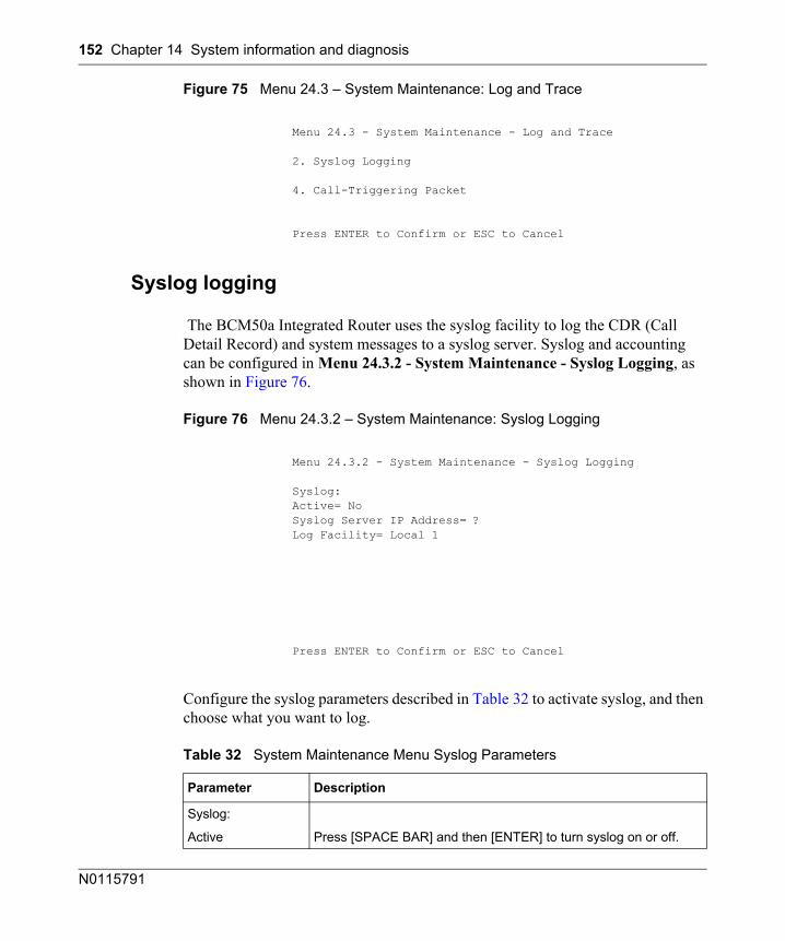
152 Chapter 14 System information and diagnosis
N0115791
Figure 75 Menu 24.3 – System Maintenance: Log and Trace
Syslog logging
The BCM50a Integrated Router uses the syslog facility to log the CDR (Call Detail Record) and system messages to a syslog server. Syslog and accounting can be configured in Menu 24.3.2 - System Maintenance - Syslog Logging, as shown in Figure 76.
Figure 76 Menu 24.3.2 – System Maintenance: Syslog Logging
Configure the syslog parameters described in Table 32 to activate syslog, and then choose what you want to log.
Menu 24.3 - System Maintenance - Log and Trace
2. Syslog Logging
4. Call-Triggering Packet
Press ENTER to Confirm or ESC to Cancel
Menu 24.3.2 - System Maintenance - Syslog Logging
Syslog:Active= NoSyslog Server IP Address= ?Log Facility= Local 1
Press ENTER to Confirm or ESC to Cancel
Table 32 System Maintenance Menu Syslog Parameters
Parameter Description
Syslog:
Active Press [SPACE BAR] and then [ENTER] to turn syslog on or off.
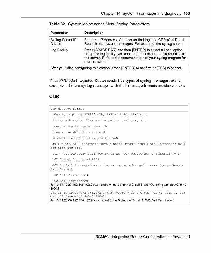
Chapter 14 System information and diagnosis 153
BCM50a Integrated Router Configuration — Advanced
Your BCM50a Integrated Router sends five types of syslog messages. Some examples of these syslog messages with their message formats are shown next:
CDR
Syslog Server IP Address
Enter the IP Address of the server that logs the CDR (Call Detail Record) and system messages. For example, the syslog server.
Log Facility Press [SPACE BAR] and then [ENTER] to select a Local option. Using the log facility, you can log the message to different files in the server. Refer to the documentation of your syslog program for more details.
After you finish configuring this screen, press [ENTER] to confirm or [ESC] to cancel.
CDR Message Format
SdcmdSyslogSend( SYSLOG_CDR, SYSLOG_INFO, String );
String = board xx line xx channel xx, call xx, str
board = the hardware board ID
line = the WAN ID in a board
Channel = channel ID within the WAN
call = the call reference number which starts from 1 and increments by 1 for each new call
str = C01 Outgoing Call dev xx ch xx (dev:device No. ch:channel No.)
L02 Tunnel Connected(L2TP)
C02 OutCall Connected xxxx (means connected speed) xxxxx (means Remote Call Number)
L02 Call Terminated
C02 Call TerminatedJul 19 11:19:27 192.168.102.2 RAS: board 0 line 0 channel 0, call 1, C01 Outgoing Call dev=2 ch=0 40002Jul 19 11:19:32 192.168.102.2 RAS: board 0 line 0 channel 0, call 1, C02 OutCall Connected 64000 40002Jul 19 11:20:06 192.168.102.2 RAS: board 0 line 0 channel 0, call 1, C02 Call Terminated
Table 32 System Maintenance Menu Syslog Parameters
Parameter Description
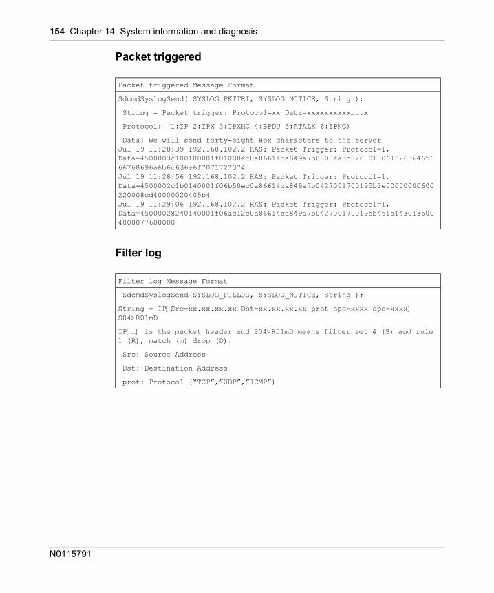
154 Chapter 14 System information and diagnosis
N0115791
Packet triggered
Filter log
Packet triggered Message Format
SdcmdSyslogSend( SYSLOG_PKTTRI, SYSLOG_NOTICE, String );
String = Packet trigger: Protocol=xx Data=xxxxxxxxxx…..x
Protocol: (1:IP 2:IPX 3:IPXHC 4:BPDU 5:ATALK 6:IPNG)
Data: We will send forty-eight Hex characters to the serverJul 19 11:28:39 192.168.102.2 RAS: Packet Trigger: Protocol=1, Data=4500003c100100001f010004c0a86614ca849a7b08004a5c020001006162636465666768696a6b6c6d6e6f7071727374Jul 19 11:28:56 192.168.102.2 RAS: Packet Trigger: Protocol=1, Data=4500002c1b0140001f06b50ec0a86614ca849a7b0427001700195b3e00000000600220008cd40000020405b4Jul 19 11:29:06 192.168.102.2 RAS: Packet Trigger: Protocol=1, Data=45000028240140001f06ac12c0a86614ca849a7b0427001700195b451d1430135004000077600000
Filter log Message Format
SdcmdSyslogSend(SYSLOG_FILLOG, SYSLOG_NOTICE, String );
String = IP[Src=xx.xx.xx.xx Dst=xx.xx.xx.xx prot spo=xxxx dpo=xxxx] S04>R01mD
IP[…] is the packet header and S04>R01mD means filter set 4 (S) and rule 1 (R), match (m) drop (D).
Src: Source Address
Dst: Destination Address
prot: Protocol (“TCP”,”UDP”,”ICMP”)
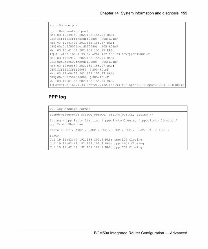
Chapter 14 System information and diagnosis 155
BCM50a Integrated Router Configuration — Advanced
PPP log
spo: Source port
dpo: Destination portMar 03 10:39:43 202.132.155.97 RAS: GEN[fffffffffffnordff0080] }S05>R01mFMar 03 10:41:29 202.132.155.97 RAS: GEN[00a0c5f502fnord010080] }S05>R01mFMar 03 10:41:34 202.132.155.97 RAS: IP[Src=192.168.1.33 Dst=202.132.155.93 ICMP]}S04>R01mFMar 03 11:59:20 202.132.155.97 RAS: GEN[00a0c5f502fnord010080] }S05>R01mFMar 03 12:00:52 202.132.155.97 RAS: GEN[ffffffffffff0080] }S05>R01mFMar 03 12:00:57 202.132.155.97 RAS: GEN[00a0c5f502010080] }S05>R01mFMar 03 12:01:06 202.132.155.97 RAS: IP[Src=192.168.1.33 Dst=202.132.155.93 TCP spo=01170 dpo=00021]}S04>R01mF
PPP Log Message Format
SdcmdSyslogSend( SYSLOG_PPPLOG, SYSLOG_NOTICE, String );
String = ppp:Proto Starting / ppp:Proto Opening / ppp:Proto Closing / ppp:Proto Shutdown
Proto = LCP / ATCP / BACP / BCP / CBCP / CCP / CHAP/ PAP / IPCP /
IPXCPJul 19 11:42:44 192.168.102.2 RAS: ppp:LCP ClosingJul 19 11:42:49 192.168.102.2 RAS: ppp:IPCP ClosingJul 19 11:42:54 192.168.102.2 RAS: ppp:CCP Closing
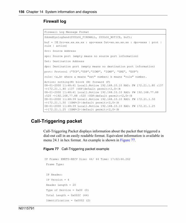
156 Chapter 14 System information and diagnosis
N0115791
Firewall log
Call-Triggering packet
Call-Triggering Packet displays information about the packet that triggered a dial-out call in an easily readable format. Equivalent information is available in menu 24.1 in hex format. An example is shown in Figure 77.
Figure 77 Call-Triggering packet example
Firewall Log Message Format
SdcmdSyslogSend(SYSLOG_FIREWALL, SYSLOG_NOTICE, buf);
buf = IP[Src=xx.xx.xx.xx : spo=xxxx Dst=xx.xx.xx.xx : dpo=xxxx | prot | rule | action]
Src: Source Address
spo: Source port (empty means no source port information)
Dst: Destination Address
dpo: Destination port (empty means no destination port information)
prot: Protocol (“TCP”,”UDP”,”ICMP”, ”IGMP”, ”GRE”, ”ESP”)
rule: <a,b> where a means "set" number; b means "rule" number.
Action: nothing(N) block (B) forward (F)08-01-2000 11:48:41 Local1.Notice 192.168.10.10 RAS: FW 172.21.1.80 :137 ->172.21.1.80 :137 |UDP|default permit:<2,0>|B08-01-2000 11:48:41 Local1.Notice 192.168.10.10 RAS: FW 192.168.77.88 :520 ->192.168.77.88 :520 |UDP|default permit:<2,0>|B08-01-2000 11:48:39 Local1.Notice 192.168.10.10 RAS: FW 172.21.1.50 ->172.21.1.50 |IGMP<2>|default permit:<2,0>|B08-01-2000 11:48:39 Local1.Notice 192.168.10.10 RAS: FW 172.21.1.25 ->172.21.1.25 |IGMP<2>|default permit:<2,0>|B
IP Frame: ENET0-RECV Size: 44/ 44 Time: 17:02:44.262
Frame Type:
IP Header:
IP Version = 4
Header Length = 20
Type of Service = 0x00 (0)
Total Length = 0x002C (44)
Identification = 0x0002 (2)
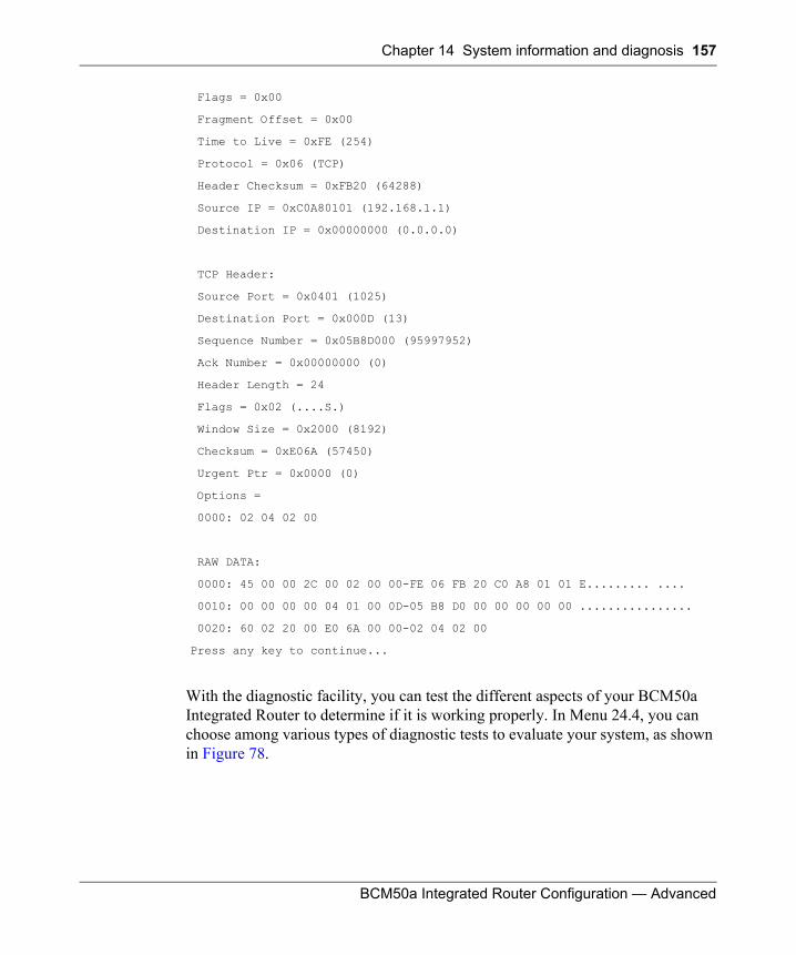
Chapter 14 System information and diagnosis 157
BCM50a Integrated Router Configuration — Advanced
With the diagnostic facility, you can test the different aspects of your BCM50a Integrated Router to determine if it is working properly. In Menu 24.4, you can choose among various types of diagnostic tests to evaluate your system, as shown in Figure 78.
Flags = 0x00
Fragment Offset = 0x00
Time to Live = 0xFE (254)
Protocol = 0x06 (TCP)
Header Checksum = 0xFB20 (64288)
Source IP = 0xC0A80101 (192.168.1.1)
Destination IP = 0x00000000 (0.0.0.0)
TCP Header:
Source Port = 0x0401 (1025)
Destination Port = 0x000D (13)
Sequence Number = 0x05B8D000 (95997952)
Ack Number = 0x00000000 (0)
Header Length = 24
Flags = 0x02 (....S.)
Window Size = 0x2000 (8192)
Checksum = 0xE06A (57450)
Urgent Ptr = 0x0000 (0)
Options =
0000: 02 04 02 00
RAW DATA:
0000: 45 00 00 2C 00 02 00 00-FE 06 FB 20 C0 A8 01 01 E......... ....
0010: 00 00 00 00 04 01 00 0D-05 B8 D0 00 00 00 00 00 ................
0020: 60 02 20 00 E0 6A 00 00-02 04 02 00
Press any key to continue...
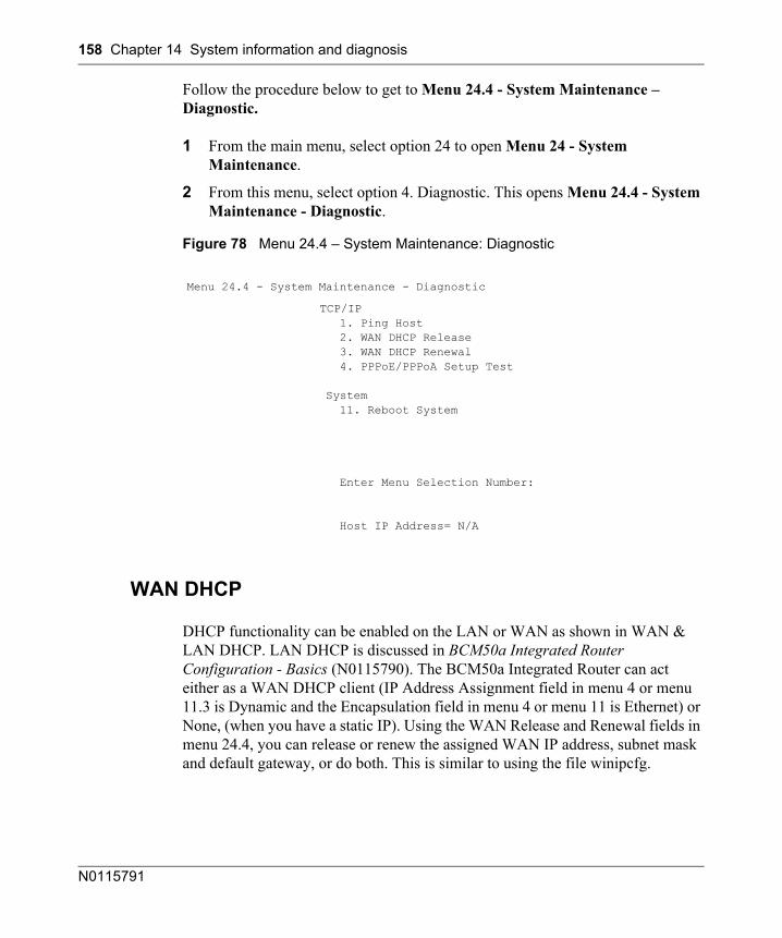
158 Chapter 14 System information and diagnosis
N0115791
Follow the procedure below to get to Menu 24.4 - System Maintenance – Diagnostic.
1 From the main menu, select option 24 to open Menu 24 - System Maintenance.
2 From this menu, select option 4. Diagnostic. This opens Menu 24.4 - System Maintenance - Diagnostic.
Figure 78 Menu 24.4 – System Maintenance: Diagnostic
WAN DHCP
DHCP functionality can be enabled on the LAN or WAN as shown in WAN & LAN DHCP. LAN DHCP is discussed in BCM50a Integrated Router Configuration - Basics (N0115790). The BCM50a Integrated Router can act either as a WAN DHCP client (IP Address Assignment field in menu 4 or menu 11.3 is Dynamic and the Encapsulation field in menu 4 or menu 11 is Ethernet) or None, (when you have a static IP). Using the WAN Release and Renewal fields in menu 24.4, you can release or renew the assigned WAN IP address, subnet mask and default gateway, or do both. This is similar to using the file winipcfg.
Menu 24.4 - System Maintenance - Diagnostic
TCP/IP 1. Ping Host 2. WAN DHCP Release 3. WAN DHCP Renewal 4. PPPoE/PPPoA Setup Test
System 11. Reboot System
Enter Menu Selection Number:
Host IP Address= N/A
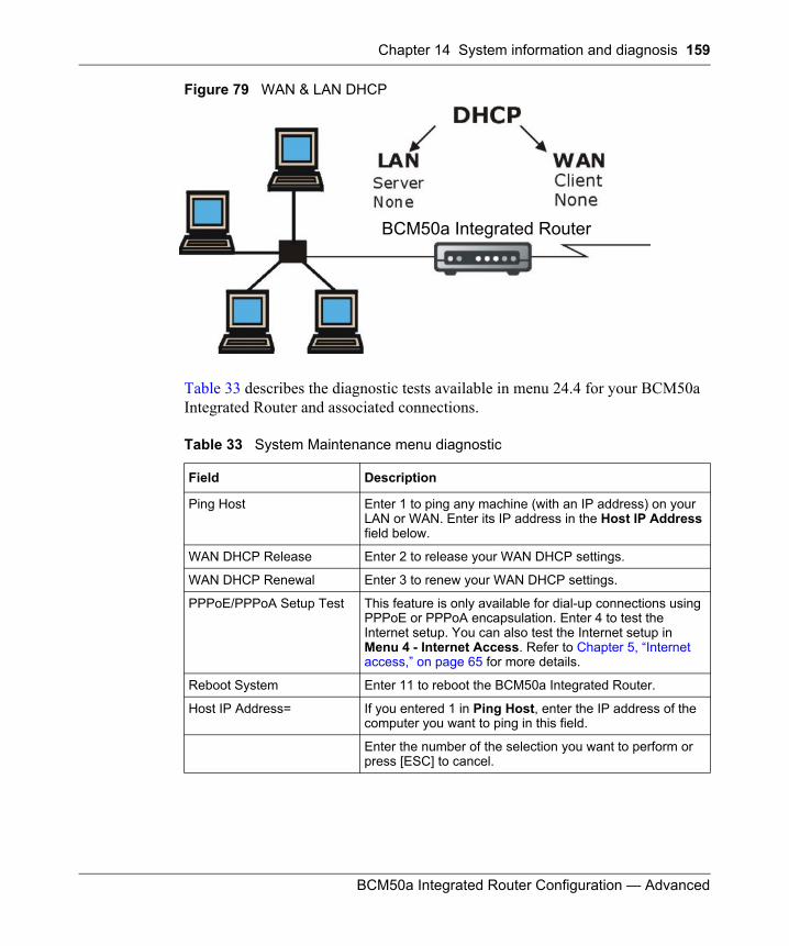
Chapter 14 System information and diagnosis 159
BCM50a Integrated Router Configuration — Advanced
Figure 79 WAN & LAN DHCP
Table 33 describes the diagnostic tests available in menu 24.4 for your BCM50a Integrated Router and associated connections.
Table 33 System Maintenance menu diagnostic
Field Description
Ping Host Enter 1 to ping any machine (with an IP address) on your LAN or WAN. Enter its IP address in the Host IP Address field below.
WAN DHCP Release Enter 2 to release your WAN DHCP settings.
WAN DHCP Renewal Enter 3 to renew your WAN DHCP settings.
PPPoE/PPPoA Setup Test This feature is only available for dial-up connections using PPPoE or PPPoA encapsulation. Enter 4 to test the Internet setup. You can also test the Internet setup in Menu 4 - Internet Access. Refer to Chapter 5, “Internet access,” on page 65 for more details.
Reboot System Enter 11 to reboot the BCM50a Integrated Router.
Host IP Address= If you entered 1 in Ping Host, enter the IP address of the computer you want to ping in this field.
Enter the number of the selection you want to perform or press [ESC] to cancel.
BCM50a Integrated Router

160 Chapter 14 System information and diagnosis
N0115791
161
BCM50a Integrated Router Configuration — Advanced
Chapter 15Firmware and configuration file maintenance
This chapter tells you how to backup and restore your configuration file, as well as upload new firmware and configuration files.
Filename conventions
The configuration file (often called the romfile or rom-0) contains the factory default settings in the menus such as password, DHCP Setup and TCP/IP Setup. It comes with a rom filename extension. Once you have customized the BCM50a Integrated Router settings, they can be saved back to your computer under a filename of your choosing.
The system firmware (sometimes referred to as the ras file) has a bin filename extension. With many FTP and TFTP clients, the filenames are similar to those seen next.
ftp> put firmware.bin ras
This is a sample FTP session showing the transfer of the computer file firmware.bin to the BCM50a Integrated Router.
ftp> get rom-0 config.cfg
This is a sample FTP session saving the current configuration to the computer file config.cfg.
Note: Only use firmware for your BCM50a Integrated Router specific model. Refer to the label on the bottom of your BCM50a Integrated Router.
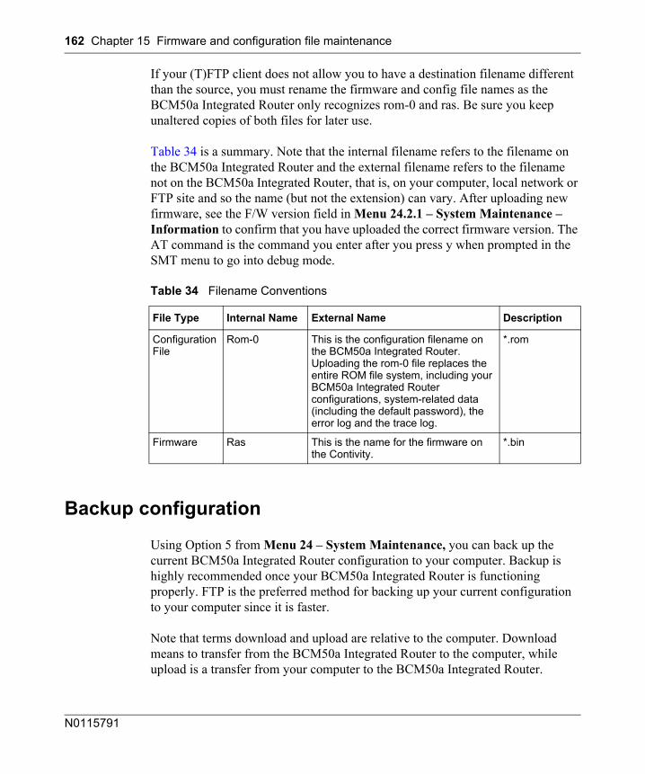
162 Chapter 15 Firmware and configuration file maintenance
N0115791
If your (T)FTP client does not allow you to have a destination filename different than the source, you must rename the firmware and config file names as the BCM50a Integrated Router only recognizes rom-0 and ras. Be sure you keep unaltered copies of both files for later use.
Table 34 is a summary. Note that the internal filename refers to the filename on the BCM50a Integrated Router and the external filename refers to the filename not on the BCM50a Integrated Router, that is, on your computer, local network or FTP site and so the name (but not the extension) can vary. After uploading new firmware, see the F/W version field in Menu 24.2.1 – System Maintenance – Information to confirm that you have uploaded the correct firmware version. The AT command is the command you enter after you press y when prompted in the SMT menu to go into debug mode.
Backup configuration
Using Option 5 from Menu 24 – System Maintenance, you can back up the current BCM50a Integrated Router configuration to your computer. Backup is highly recommended once your BCM50a Integrated Router is functioning properly. FTP is the preferred method for backing up your current configuration to your computer since it is faster.
Note that terms download and upload are relative to the computer. Download means to transfer from the BCM50a Integrated Router to the computer, while upload is a transfer from your computer to the BCM50a Integrated Router.
Table 34 Filename Conventions
File Type Internal Name External Name Description
Configuration File
Rom-0 This is the configuration filename on the BCM50a Integrated Router. Uploading the rom-0 file replaces the entire ROM file system, including your BCM50a Integrated Router configurations, system-related data (including the default password), the error log and the trace log.
*.rom
Firmware Ras This is the name for the firmware on the Contivity.
*.bin
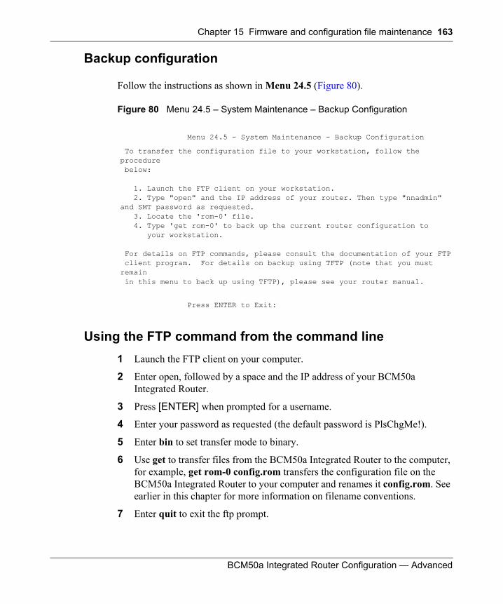
Chapter 15 Firmware and configuration file maintenance 163
BCM50a Integrated Router Configuration — Advanced
Backup configuration
Follow the instructions as shown in Menu 24.5 (Figure 80).
Figure 80 Menu 24.5 – System Maintenance – Backup Configuration
Using the FTP command from the command line1 Launch the FTP client on your computer.
2 Enter open, followed by a space and the IP address of your BCM50a Integrated Router.
3 Press [ENTER] when prompted for a username.
4 Enter your password as requested (the default password is PlsChgMe!).
5 Enter bin to set transfer mode to binary.
6 Use get to transfer files from the BCM50a Integrated Router to the computer, for example, get rom-0 config.rom transfers the configuration file on the BCM50a Integrated Router to your computer and renames it config.rom. See earlier in this chapter for more information on filename conventions.
7 Enter quit to exit the ftp prompt.
Menu 24.5 - System Maintenance - Backup Configuration
To transfer the configuration file to your workstation, follow the procedure below:
1. Launch the FTP client on your workstation. 2. Type "open" and the IP address of your router. Then type "nnadmin" and SMT password as requested. 3. Locate the 'rom-0' file. 4. Type 'get rom-0' to back up the current router configuration to your workstation.
For details on FTP commands, please consult the documentation of your FTP client program. For details on backup using TFTP (note that you must remain in this menu to back up using TFTP), please see your router manual.
Press ENTER to Exit:
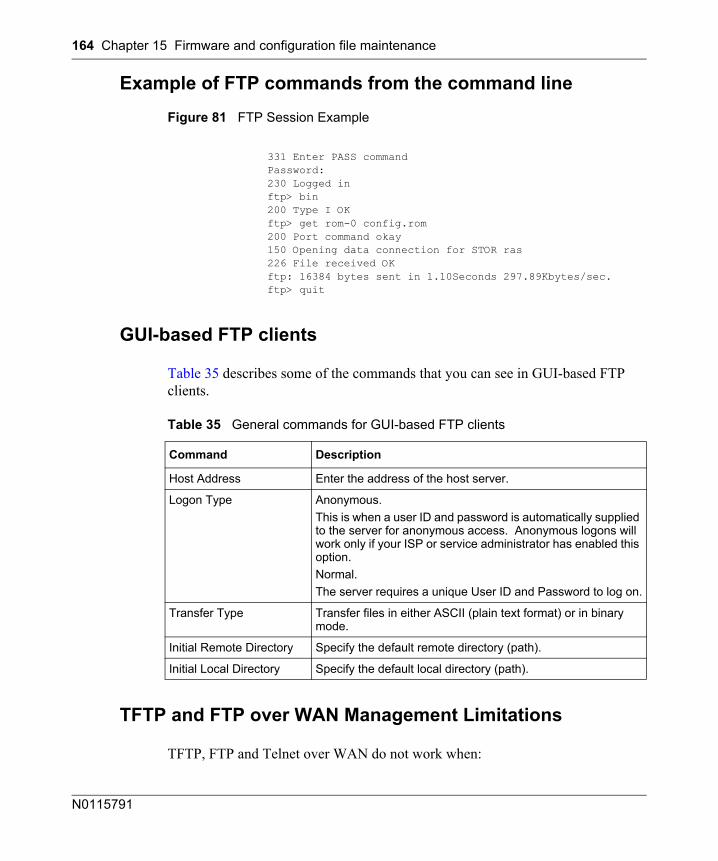
164 Chapter 15 Firmware and configuration file maintenance
N0115791
Example of FTP commands from the command line
Figure 81 FTP Session Example
GUI-based FTP clients
Table 35 describes some of the commands that you can see in GUI-based FTP clients.
TFTP and FTP over WAN Management Limitations
TFTP, FTP and Telnet over WAN do not work when:
331 Enter PASS commandPassword:230 Logged inftp> bin200 Type I OKftp> get rom-0 config.rom200 Port command okay150 Opening data connection for STOR ras226 File received OKftp: 16384 bytes sent in 1.10Seconds 297.89Kbytes/sec.ftp> quit
Table 35 General commands for GUI-based FTP clients
Command Description
Host Address Enter the address of the host server.
Logon Type Anonymous.This is when a user ID and password is automatically supplied to the server for anonymous access. Anonymous logons will work only if your ISP or service administrator has enabled this option.Normal. The server requires a unique User ID and Password to log on.
Transfer Type Transfer files in either ASCII (plain text format) or in binary mode.
Initial Remote Directory Specify the default remote directory (path).
Initial Local Directory Specify the default local directory (path).
Chapter 15 Firmware and configuration file maintenance 165
BCM50a Integrated Router Configuration — Advanced
• You disable Telnet service in menu 24.11.• You apply a filter in menu 3.1 (LAN) or in menu 11.1.4 (WAN) to block
Telnet service.• The IP address in the Secured Client IP field in menu 24.11 does not match
the client IP. If it does not match, the BCM50a Integrated Router disconnects the Telnet session immediately.
Backup configuration using TFTP
The BCM50a Integrated Router supports the uploading and downloading of the firmware and the configuration file using TFTP (Trivial File Transfer Protocol) over LAN. Nortel does not recommend using TFTP over WAN, although it can work.
To use TFTP, your computer must have both Telnet and TFTP clients. To back up the configuration file, follow the procedure shown next.
1 Use Telnet from your computer to connect to the BCM50a Integrated Router and log on. Because TFTP does not have any security checks, the BCM50a Integrated Router records the IP address of the Telnet client and accepts TFTP requests only from this address.
2 Put the SMT in command interpreter (CI) mode by entering 8 in Menu 24 – System Maintenance.
3 Enter command “sys stdio 0” to disable the SMT timeout, so the TFTP transfer is not interrupted. Enter command “sys stdio 5” to restore the five-minute SMT timeout (default) after the file transfer is complete.
4 Launch the TFTP client on your computer and connect to the BCM50a Integrated Router. Set the transfer mode to binary before starting data transfer.
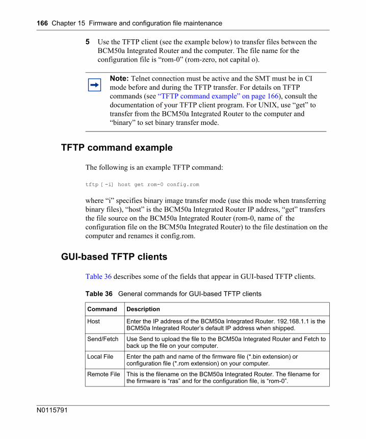
166 Chapter 15 Firmware and configuration file maintenance
N0115791
5 Use the TFTP client (see the example below) to transfer files between the BCM50a Integrated Router and the computer. The file name for the configuration file is “rom-0” (rom-zero, not capital o).
TFTP command example
The following is an example TFTP command:
tftp [-i] host get rom-0 config.rom
where “i” specifies binary image transfer mode (use this mode when transferring binary files), “host” is the BCM50a Integrated Router IP address, “get” transfers the file source on the BCM50a Integrated Router (rom-0, name of the configuration file on the BCM50a Integrated Router) to the file destination on the computer and renames it config.rom.
GUI-based TFTP clients
Table 36 describes some of the fields that appear in GUI-based TFTP clients.
Note: Telnet connection must be active and the SMT must be in CI mode before and during the TFTP transfer. For details on TFTP commands (see “TFTP command example” on page 166), consult the documentation of your TFTP client program. For UNIX, use “get” to transfer from the BCM50a Integrated Router to the computer and “binary” to set binary transfer mode.
Table 36 General commands for GUI-based TFTP clients
Command Description
Host Enter the IP address of the BCM50a Integrated Router. 192.168.1.1 is the BCM50a Integrated Router’s default IP address when shipped.
Send/Fetch Use Send to upload the file to the BCM50a Integrated Router and Fetch to back up the file on your computer.
Local File Enter the path and name of the firmware file (*.bin extension) or configuration file (*.rom extension) on your computer.
Remote File This is the filename on the BCM50a Integrated Router. The filename for the firmware is “ras” and for the configuration file, is “rom-0”.
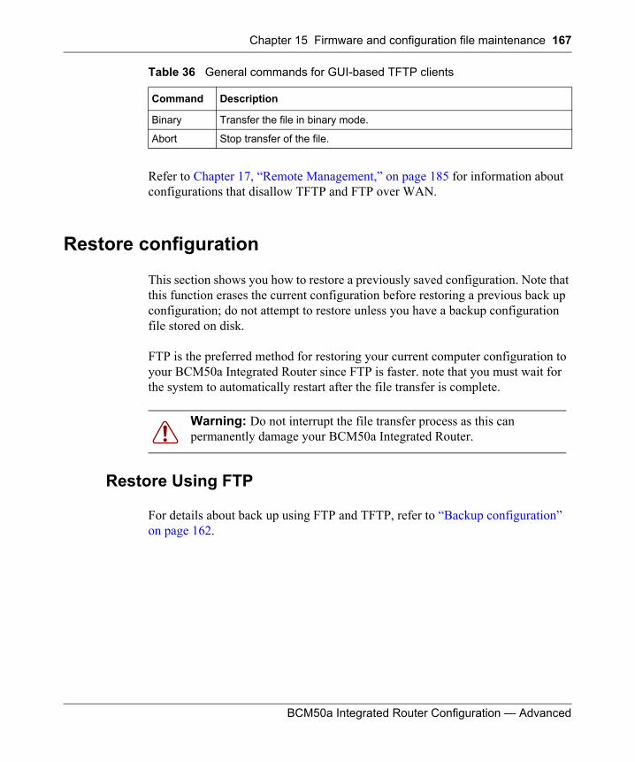
Chapter 15 Firmware and configuration file maintenance 167
BCM50a Integrated Router Configuration — Advanced
Refer to Chapter 17, “Remote Management,” on page 185 for information about configurations that disallow TFTP and FTP over WAN.
Restore configuration
This section shows you how to restore a previously saved configuration. Note that this function erases the current configuration before restoring a previous back up configuration; do not attempt to restore unless you have a backup configuration file stored on disk.
FTP is the preferred method for restoring your current computer configuration to your BCM50a Integrated Router since FTP is faster. note that you must wait for the system to automatically restart after the file transfer is complete.
Restore Using FTP
For details about back up using FTP and TFTP, refer to “Backup configuration” on page 162.
Binary Transfer the file in binary mode.
Abort Stop transfer of the file.
Warning: Do not interrupt the file transfer process as this can permanently damage your BCM50a Integrated Router.
Table 36 General commands for GUI-based TFTP clients
Command Description
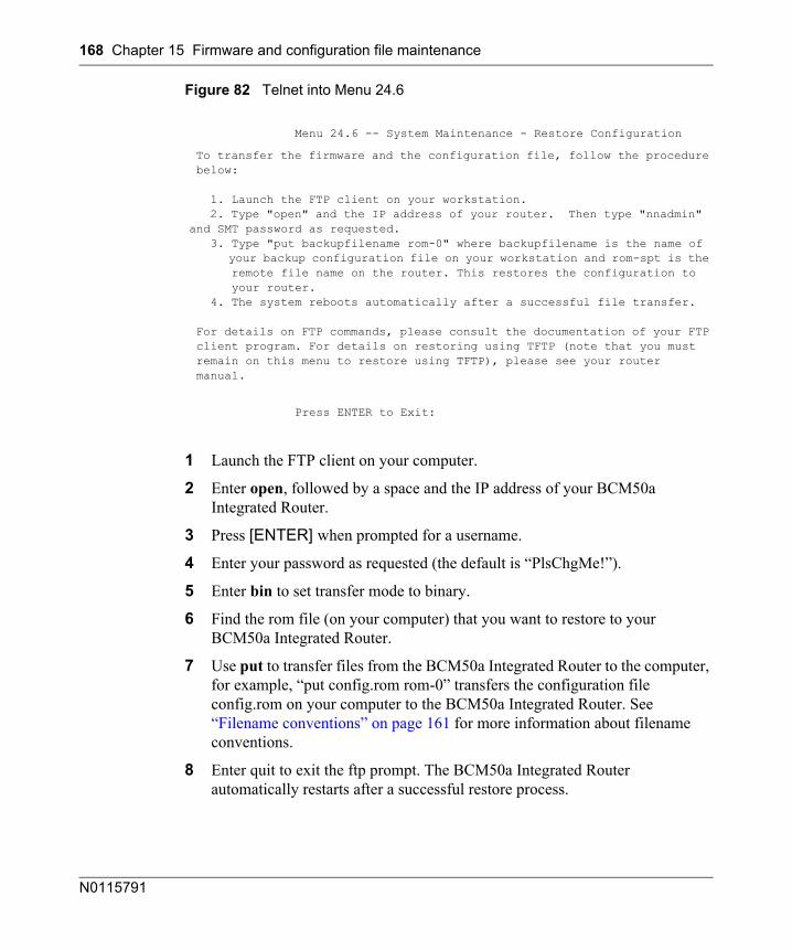
168 Chapter 15 Firmware and configuration file maintenance
N0115791
Figure 82 Telnet into Menu 24.6
1 Launch the FTP client on your computer.
2 Enter open, followed by a space and the IP address of your BCM50a Integrated Router.
3 Press [ENTER] when prompted for a username.
4 Enter your password as requested (the default is “PlsChgMe!”).
5 Enter bin to set transfer mode to binary.
6 Find the rom file (on your computer) that you want to restore to your BCM50a Integrated Router.
7 Use put to transfer files from the BCM50a Integrated Router to the computer, for example, “put config.rom rom-0” transfers the configuration file config.rom on your computer to the BCM50a Integrated Router. See “Filename conventions” on page 161 for more information about filename conventions.
8 Enter quit to exit the ftp prompt. The BCM50a Integrated Router automatically restarts after a successful restore process.
Menu 24.6 -- System Maintenance - Restore Configuration
To transfer the firmware and the configuration file, follow the procedure below:
1. Launch the FTP client on your workstation. 2. Type "open" and the IP address of your router. Then type "nnadmin" and SMT password as requested. 3. Type "put backupfilename rom-0" where backupfilename is the name of your backup configuration file on your workstation and rom-spt is the remote file name on the router. This restores the configuration to your router. 4. The system reboots automatically after a successful file transfer.
For details on FTP commands, please consult the documentation of your FTP client program. For details on restoring using TFTP (note that you must remain on this menu to restore using TFTP), please see your router manual.
Press ENTER to Exit:
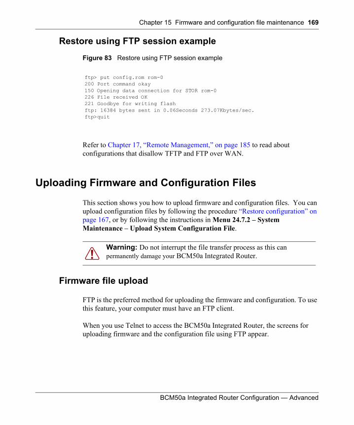
Chapter 15 Firmware and configuration file maintenance 169
BCM50a Integrated Router Configuration — Advanced
Restore using FTP session example
Figure 83 Restore using FTP session example
Refer to Chapter 17, “Remote Management,” on page 185 to read about configurations that disallow TFTP and FTP over WAN.
Uploading Firmware and Configuration Files
This section shows you how to upload firmware and configuration files. You can upload configuration files by following the procedure “Restore configuration” on page 167, or by following the instructions in Menu 24.7.2 – System Maintenance – Upload System Configuration File.
Firmware file upload
FTP is the preferred method for uploading the firmware and configuration. To use this feature, your computer must have an FTP client.
When you use Telnet to access the BCM50a Integrated Router, the screens for uploading firmware and the configuration file using FTP appear.
ftp> put config.rom rom-0200 Port command okay150 Opening data connection for STOR rom-0226 File received OK221 Goodbye for writing flashftp: 16384 bytes sent in 0.06Seconds 273.07Kbytes/sec.ftp>quit
Warning: Do not interrupt the file transfer process as this can permanently damage your BCM50a Integrated Router.
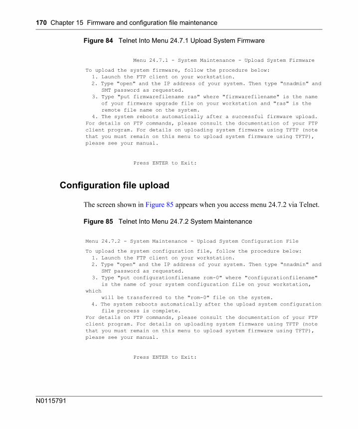
170 Chapter 15 Firmware and configuration file maintenance
N0115791
Figure 84 Telnet Into Menu 24.7.1 Upload System Firmware
Configuration file upload
The screen shown in Figure 85 appears when you access menu 24.7.2 via Telnet.
Figure 85 Telnet Into Menu 24.7.2 System Maintenance
Menu 24.7.1 - System Maintenance - Upload System Firmware
To upload the system firmware, follow the procedure below: 1. Launch the FTP client on your workstation. 2. Type "open" and the IP address of your system. Then type "nnadmin" and SMT password as requested. 3. Type "put firmwarefilename ras" where "firmwarefilename" is the name of your firmware upgrade file on your workstation and "ras" is the remote file name on the system. 4. The system reboots automatically after a successful firmware upload.For details on FTP commands, please consult the documentation of your FTPclient program. For details on uploading system firmware using TFTP (notethat you must remain on this menu to upload system firmware using TFTP),please see your manual.
Press ENTER to Exit:
Menu 24.7.2 - System Maintenance - Upload System Configuration File
To upload the system configuration file, follow the procedure below: 1. Launch the FTP client on your workstation. 2. Type "open" and the IP address of your system. Then type "nnadmin" and SMT password as requested. 3. Type "put configurationfilename rom-0" where "configurationfilename" is the name of your system configuration file on your workstation, which will be transferred to the "rom-0" file on the system. 4. The system reboots automatically after the upload system configuration file process is complete.For details on FTP commands, please consult the documentation of your FTPclient program. For details on uploading system firmware using TFTP (notethat you must remain on this menu to upload system firmware using TFTP),please see your manual.
Press ENTER to Exit:

Chapter 15 Firmware and configuration file maintenance 171
BCM50a Integrated Router Configuration — Advanced
To upload the firmware and the configuration files, follow the examples in the rest of this chapter:
FTP file upload command from the DOS prompt example1 Launch the FTP client on your computer.
2 Enter “open”, followed by a space and the IP address of your BCM50a Integrated Router.
3 Press [ENTER] when prompted for a username.
4 Enter your password as requested (the default is “PlsChgMe!”).
5 Enter “bin” to set transfer mode to binary.
6 Use “put” to transfer files from the computer to the BCM50a Integrated Router, for example, “put firmware.bin ras” transfers the firmware on your computer (firmware.bin) to the BCM50a Integrated Router and renames it “ras”. Similarly, “put config.rom rom-0” transfers the configuration file on your computer (config.rom) to the BCM50a Integrated Router and renames it rom-0. Likewise get rom-0 config.rom transfers the configuration file on the BCM50a Integrated Router to your computer and renames it “config.rom.” See “Filename conventions” on page 161 for more information about filename conventions.
7 Enter “quit” to exit the ftp prompt.
Note: The BCM50a Integrated Router automatically restarts after a successful file upload.
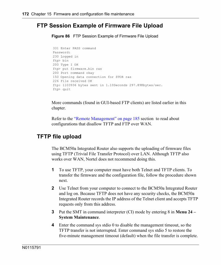
172 Chapter 15 Firmware and configuration file maintenance
N0115791
FTP Session Example of Firmware File Upload
Figure 86 FTP Session Example of Firmware File Upload
More commands (found in GUI-based FTP clients) are listed earlier in this chapter.
Refer to the “Remote Management” on page 185 section to read about configurations that disallow TFTP and FTP over WAN.
TFTP file upload
The BCM50a Integrated Router also supports the uploading of firmware files using TFTP (Trivial File Transfer Protocol) over LAN. Although TFTP also works over WAN, Nortel does not recommend doing this.
1 To use TFTP, your computer must have both Telnet and TFTP clients. To transfer the firmware and the configuration file, follow the procedure shown next.
2 Use Telnet from your computer to connect to the BCM50a Integrated Router and log on. Because TFTP does not have any security checks, the BCM50a Integrated Router records the IP address of the Telnet client and accepts TFTP requests only from this address.
3 Put the SMT in command interpreter (CI) mode by entering 8 in Menu 24 – System Maintenance.
4 Enter the command sys stdio 0 to disable the management timeout, so the TFTP transfer is not interrupted. Enter command sys stdio 5 to restore the five-minute management timeout (default) when the file transfer is complete.
331 Enter PASS commandPassword:230 Logged inftp> bin200 Type I OKftp> put firmware.bin ras200 Port command okay150 Opening data connection for STOR ras226 File received OKftp: 1103936 bytes sent in 1.10Seconds 297.89Kbytes/sec.ftp> quit
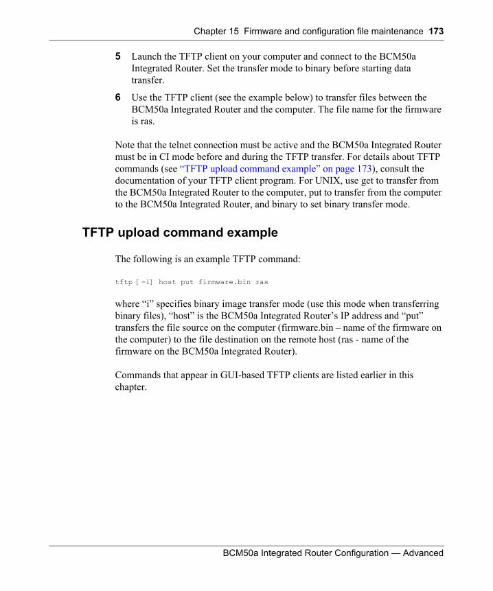
Chapter 15 Firmware and configuration file maintenance 173
BCM50a Integrated Router Configuration — Advanced
5 Launch the TFTP client on your computer and connect to the BCM50a Integrated Router. Set the transfer mode to binary before starting data transfer.
6 Use the TFTP client (see the example below) to transfer files between the BCM50a Integrated Router and the computer. The file name for the firmware is ras.
Note that the telnet connection must be active and the BCM50a Integrated Router must be in CI mode before and during the TFTP transfer. For details about TFTP commands (see “TFTP upload command example” on page 173), consult the documentation of your TFTP client program. For UNIX, use get to transfer from the BCM50a Integrated Router to the computer, put to transfer from the computer to the BCM50a Integrated Router, and binary to set binary transfer mode.
TFTP upload command example
The following is an example TFTP command:
tftp [-i] host put firmware.bin ras
where “i” specifies binary image transfer mode (use this mode when transferring binary files), “host” is the BCM50a Integrated Router’s IP address and “put” transfers the file source on the computer (firmware.bin – name of the firmware on the computer) to the file destination on the remote host (ras - name of the firmware on the BCM50a Integrated Router).
Commands that appear in GUI-based TFTP clients are listed earlier in this chapter.

174 Chapter 15 Firmware and configuration file maintenance
N0115791
175
BCM50a Integrated Router Configuration — Advanced
Chapter 16System Maintenance menus 8 to 10
This chapter leads you through SMT menus 24.8 to 24.10.
Command Interpreter mode
The Command Interpreter (CI) is a part of the main router firmware. The CI provides much of the same functionality as the SMT, while adding some low-level setup and diagnostic functions. Enter the CI from the SMT by selecting menu 24.8. Access can be by Telnet connection, although some commands are only available with a serial connection. See the included disk or www.nortel.com for more detailed information about CI commands. Enter 8 from Menu 24 - System Maintenance.
Note: Use of undocumented commands or misconfiguration can damage the unit and possibly render it unusable.
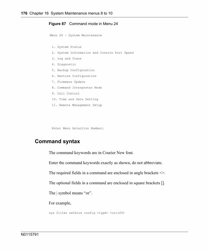
176 Chapter 16 System Maintenance menus 8 to 10
N0115791
Figure 87 Command mode in Menu 24
Command syntax
The command keywords are in Courier New font.
Enter the command keywords exactly as shown, do not abbreviate.
The required fields in a command are enclosed in angle brackets <>.
The optional fields in a command are enclosed in square brackets [].
The | symbol means “or”.
For example,
sys filter netbios config <type> <on|off>
Menu 24 - System Maintenance
1. System Status
2. System Information and Console Port Speed
3. Log and Trace
4. Diagnostic
5. Backup Configuration
6. Restore Configuration
7. Firmware Update
8. Command Interpreter Mode
9. Call Control
10. Time and Date Setting
11. Remote Management Setup
Enter Menu Selection Number:
Chapter 16 System Maintenance menus 8 to 10 177
BCM50a Integrated Router Configuration — Advanced
means that you must specify the type of netbios filter and whether to turn it on or off.
Command usage
A list of commands can be found by typing “help” or “?” at the command prompt. Always type the full command. Type “exit” to return to the SMT main menu when finished. See Appendix G, “Command Interpreter,” on page 241 for details on the commands.
Call control support
The BCM50a Integrated Router provides two call control functions: budget management and call history. Note that this menu is only applicable when Encapsulation is set to PPPoE or PPPoA in menu 4 or menu 11.1.
With the budget management function, you can set a limit on the total outgoing call time of the BCM50a Integrated Router within certain times. When the total outgoing call time exceeds the limit, the current call is dropped and any future outgoing calls are blocked.
Call history chronicles preceding incoming and outgoing calls.
To access the call control menu, select option 9 in menu 24 to go to Menu 24.9 - System Maintenance - Call Control, as shown in Figure 88.

178 Chapter 16 System Maintenance menus 8 to 10
N0115791
Figure 88 Call Control
Budget management
Menu 24.9.1 shows the budget management statistics for outgoing calls. Enter 1 from Menu 24.9 - System Maintenance - Call Control to bring up the Budget Management menu (Figure 89).
Menu 24.9 - System Maintenance - Call Control
1.Budget Management 2.Call History
Enter Menu Selection Number:
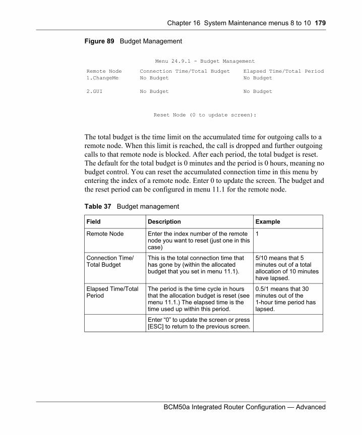
Chapter 16 System Maintenance menus 8 to 10 179
BCM50a Integrated Router Configuration — Advanced
Figure 89 Budget Management
The total budget is the time limit on the accumulated time for outgoing calls to a remote node. When this limit is reached, the call is dropped and further outgoing calls to that remote node is blocked. After each period, the total budget is reset. The default for the total budget is 0 minutes and the period is 0 hours, meaning no budget control. You can reset the accumulated connection time in this menu by entering the index of a remote node. Enter 0 to update the screen. The budget and the reset period can be configured in menu 11.1 for the remote node.
Menu 24.9.1 - Budget Management
Remote Node1.ChangeMe
2.GUI
Connection Time/Total BudgetNo Budget
No Budget
Elapsed Time/Total PeriodNo Budget
No Budget
Reset Node (0 to update screen):
Table 37 Budget management
Field Description Example
Remote Node Enter the index number of the remote node you want to reset (just one in this case)
1
Connection Time/Total Budget
This is the total connection time that has gone by (within the allocated budget that you set in menu 11.1).
5/10 means that 5 minutes out of a total allocation of 10 minutes have lapsed.
Elapsed Time/Total Period
The period is the time cycle in hours that the allocation budget is reset (see menu 11.1.) The elapsed time is the time used up within this period.
0.5/1 means that 30 minutes out of the 1-hour time period has lapsed.
Enter “0” to update the screen or press [ESC] to return to the previous screen.
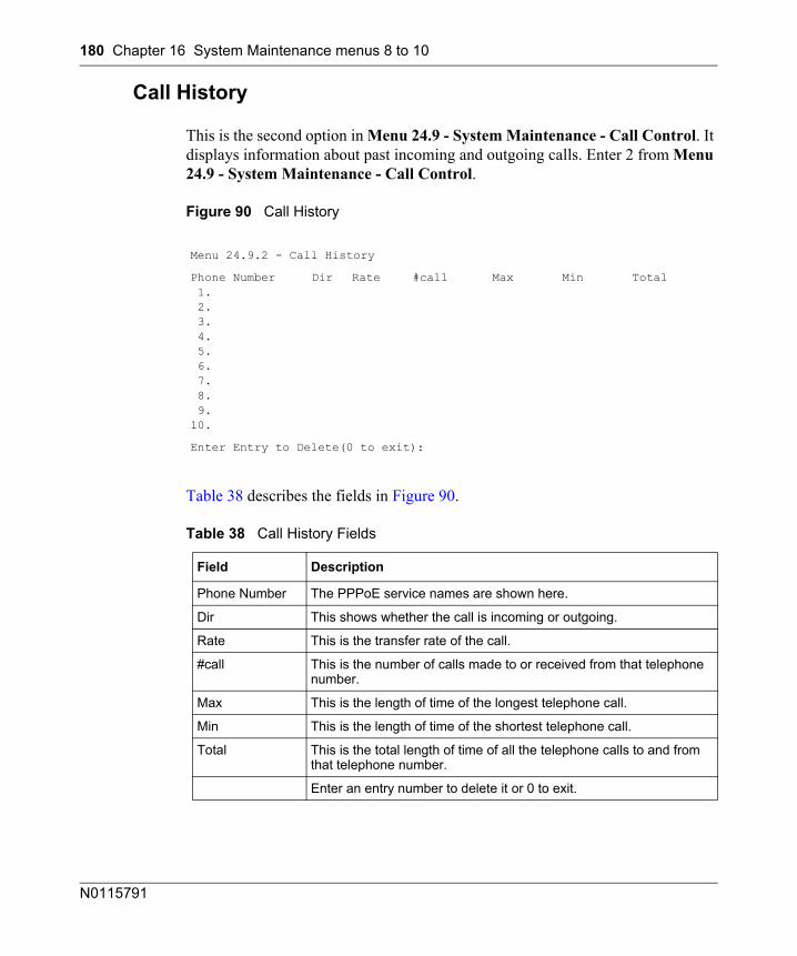
180 Chapter 16 System Maintenance menus 8 to 10
N0115791
Call History
This is the second option in Menu 24.9 - System Maintenance - Call Control. It displays information about past incoming and outgoing calls. Enter 2 from Menu 24.9 - System Maintenance - Call Control.
Figure 90 Call History
Table 38 describes the fields in Figure 90.
Menu 24.9.2 - Call History
Phone Number 1. 2. 3. 4. 5. 6. 7. 8. 9.10.
Dir Rate #call Max Min Total
Enter Entry to Delete(0 to exit):
Table 38 Call History Fields
Field Description
Phone Number The PPPoE service names are shown here.
Dir This shows whether the call is incoming or outgoing.
Rate This is the transfer rate of the call.
#call This is the number of calls made to or received from that telephone number.
Max This is the length of time of the longest telephone call.
Min This is the length of time of the shortest telephone call.
Total This is the total length of time of all the telephone calls to and from that telephone number.
Enter an entry number to delete it or 0 to exit.
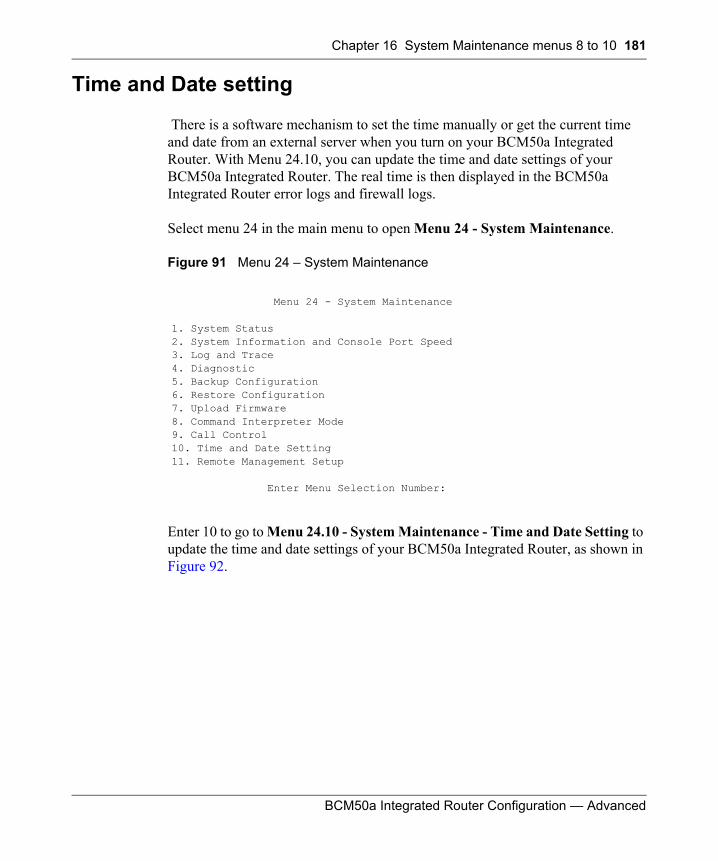
Chapter 16 System Maintenance menus 8 to 10 181
BCM50a Integrated Router Configuration — Advanced
Time and Date setting
There is a software mechanism to set the time manually or get the current time and date from an external server when you turn on your BCM50a Integrated Router. With Menu 24.10, you can update the time and date settings of your BCM50a Integrated Router. The real time is then displayed in the BCM50a Integrated Router error logs and firewall logs.
Select menu 24 in the main menu to open Menu 24 - System Maintenance.
Figure 91 Menu 24 – System Maintenance
Enter 10 to go to Menu 24.10 - System Maintenance - Time and Date Setting to update the time and date settings of your BCM50a Integrated Router, as shown in Figure 92.
Menu 24 - System Maintenance
1. System Status2. System Information and Console Port Speed3. Log and Trace4. Diagnostic5. Backup Configuration6. Restore Configuration7. Upload Firmware8. Command Interpreter Mode9. Call Control10. Time and Date Setting11. Remote Management Setup
Enter Menu Selection Number:
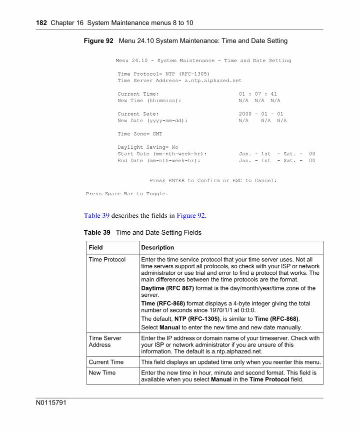
182 Chapter 16 System Maintenance menus 8 to 10
N0115791
Figure 92 Menu 24.10 System Maintenance: Time and Date Setting
Table 39 describes the fields in Figure 92.
Menu 24.10 - System Maintenance - Time and Date Setting
Time Protocol= NTP (RFC-1305) Time Server Address= a.ntp.alphazed.net
Current Time: 01 : 07 : 41 New Time (hh:mm:ss): N/A N/A N/A
Current Date: 2000 - 01 - 01 New Date (yyyy-mm-dd): N/A N/A N/A
Time Zone= GMT
Daylight Saving= No Start Date (mm-nth-week-hr): Jan. - 1st - Sat. - 00 End Date (mm-nth-week-hr): Jan. - 1st - Sat. - 00
Press ENTER to Confirm or ESC to Cancel:
Press Space Bar to Toggle.
Table 39 Time and Date Setting Fields
Field Description
Time Protocol Enter the time service protocol that your time server uses. Not all time servers support all protocols, so check with your ISP or network administrator or use trial and error to find a protocol that works. The main differences between the time protocols are the format. Daytime (RFC 867) format is the day/month/year/time zone of the server.Time (RFC-868) format displays a 4-byte integer giving the total number of seconds since 1970/1/1 at 0:0:0.The default, NTP (RFC-1305), is similar to Time (RFC-868).Select Manual to enter the new time and new date manually.
Time Server Address
Enter the IP address or domain name of your timeserver. Check with your ISP or network administrator if you are unsure of this information. The default is a.ntp.alphazed.net.
Current Time This field displays an updated time only when you reenter this menu.
New Time Enter the new time in hour, minute and second format. This field is available when you select Manual in the Time Protocol field.
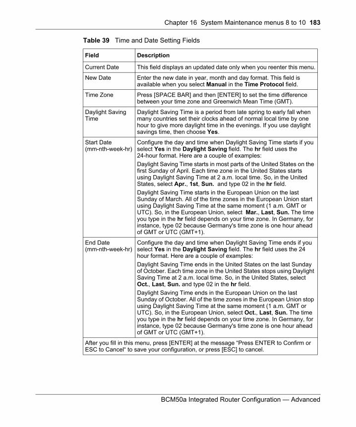
Chapter 16 System Maintenance menus 8 to 10 183
BCM50a Integrated Router Configuration — Advanced
Current Date This field displays an updated date only when you reenter this menu.
New Date Enter the new date in year, month and day format. This field is available when you select Manual in the Time Protocol field.
Time Zone Press [SPACE BAR] and then [ENTER] to set the time difference between your time zone and Greenwich Mean Time (GMT).
Daylight Saving Time
Daylight Saving Time is a period from late spring to early fall when many countries set their clocks ahead of normal local time by one hour to give more daylight time in the evenings. If you use daylight savings time, then choose Yes.
Start Date (mm-nth-week-hr)
Configure the day and time when Daylight Saving Time starts if you select Yes in the Daylight Saving field. The hr field uses the 24-hour format. Here are a couple of examples:Daylight Saving Time starts in most parts of the United States on the first Sunday of April. Each time zone in the United States starts using Daylight Saving Time at 2 a.m. local time. So, in the United States, select Apr., 1st, Sun. and type 02 in the hr field.Daylight Saving Time starts in the European Union on the last Sunday of March. All of the time zones in the European Union start using Daylight Saving Time at the same moment (1 a.m. GMT or UTC). So, in the European Union, select Mar., Last, Sun. The time you type in the hr field depends on your time zone. In Germany, for instance, type 02 because Germany's time zone is one hour ahead of GMT or UTC (GMT+1).
End Date (mm-nth-week-hr)
Configure the day and time when Daylight Saving Time ends if you select Yes in the Daylight Saving field. The hr field uses the 24 hour format. Here are a couple of examples:Daylight Saving Time ends in the United States on the last Sunday of October. Each time zone in the United States stops using Daylight Saving Time at 2 a.m. local time. So, in the United States, select Oct., Last, Sun. and type 02 in the hr field.Daylight Saving Time ends in the European Union on the last Sunday of October. All of the time zones in the European Union stop using Daylight Saving Time at the same moment (1 a.m. GMT or UTC). So, in the European Union, select Oct., Last, Sun. The time you type in the hr field depends on your time zone. In Germany, for instance, type 02 because Germany's time zone is one hour ahead of GMT or UTC (GMT+1).
After you fill in this menu, press [ENTER] at the message “Press ENTER to Confirm or ESC to Cancel“ to save your configuration, or press [ESC] to cancel.
Table 39 Time and Date Setting Fields
Field Description
184 Chapter 16 System Maintenance menus 8 to 10
N0115791
Resetting the Time
The BCM50a Integrated Router resets the time in three instances:
• After you make changes to and leave menu 24.10 • After starting up the BCM50a Integrated Router starts up, if a time server
configured in menu 24.10• After starting the BCM50a Integrated Router, in 24-hour intervals
185
BCM50a Integrated Router Configuration — Advanced
Chapter 17Remote Management
This chapter covers remote management found in SMT menu 24.11.
Remote Management
With remote management, you can determine which services and protocols can access which BCM50a Integrated Router interface (if any) from which computers.
You can manage your BCM50a Integrated Router from a remote location via:
• Internet (WAN only)• ALL (LAN and WAN)• LAN only• Neither (Disable)
To disable remote management of a service, select Disable in the corresponding Server Access field.
Enter 11 from menu 24 to bring up Menu 24.11 – Remote Management Control.
Note: When you Choose WAN only or ALL (LAN & WAN), you still need to configure a firewall rule to allow access.
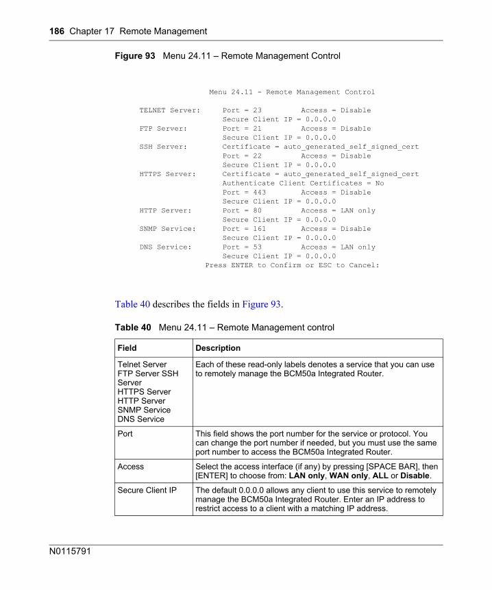
186 Chapter 17 Remote Management
N0115791
Figure 93 Menu 24.11 – Remote Management Control
Table 40 describes the fields in Figure 93.
Menu 24.11 - Remote Management Control
TELNET Server: Port = 23 Access = Disable Secure Client IP = 0.0.0.0 FTP Server: Port = 21 Access = Disable Secure Client IP = 0.0.0.0 SSH Server: Certificate = auto_generated_self_signed_cert Port = 22 Access = Disable Secure Client IP = 0.0.0.0 HTTPS Server: Certificate = auto_generated_self_signed_cert Authenticate Client Certificates = No Port = 443 Access = Disable Secure Client IP = 0.0.0.0 HTTP Server: Port = 80 Access = LAN only Secure Client IP = 0.0.0.0 SNMP Service: Port = 161 Access = Disable Secure Client IP = 0.0.0.0 DNS Service: Port = 53 Access = LAN only Secure Client IP = 0.0.0.0 Press ENTER to Confirm or ESC to Cancel:
Table 40 Menu 24.11 – Remote Management control
Field Description
Telnet ServerFTP Server SSH ServerHTTPS ServerHTTP ServerSNMP ServiceDNS Service
Each of these read-only labels denotes a service that you can use to remotely manage the BCM50a Integrated Router.
Port This field shows the port number for the service or protocol. You can change the port number if needed, but you must use the same port number to access the BCM50a Integrated Router.
Access Select the access interface (if any) by pressing [SPACE BAR], then [ENTER] to choose from: LAN only, WAN only, ALL or Disable.
Secure Client IP The default 0.0.0.0 allows any client to use this service to remotely manage the BCM50a Integrated Router. Enter an IP address to restrict access to a client with a matching IP address.
Chapter 17 Remote Management 187
BCM50a Integrated Router Configuration — Advanced
Remote Management Limitations
Remote management over LAN or WAN does not work when:
1 A filter in menu 3.1 (LAN) or in menu 11.1.4 (WAN) is applied to block a Telnet, FTP, or Web service.
2 You disable that service in menu 24.11.
3 The IP address in the Secured Client IP field (menu 24.11) does not match the client IP address. If it does not match, the BCM50a Integrated Router disconnects the session immediately.
4 There is already another remote management session of the same type (web, FTP or Telnet) running. Only one remote management session of the same type can run at one time.
5 There is a web remote management session running with a Telnet session. A Telnet session is disconnected if you begin a web session; it does not begin if a Web session is already running.
6 There is a firewall rule that blocks remote management.
Certificate Press [SPACE BAR] and then [ENTER] to select the certificate that the BCM50a Integrated Router uses to identify itself. The BCM50a Integrated Router is the SSL server and must always authenticate itself to the SSL client (the computer that requests the HTTPS connection with the BCM50a Integrated Router).
Authenticate Client Certificates
Select Yes by pressing [SPACE BAR], then [ENTER] to require the SSL client to authenticate itself to the BCM50a Integrated Router by sending the BCM50a Integrated Router a certificate. To do that, the SSL client must have a CA-signed certificate from a CA that has been imported as a trusted CA on the BCM50a Integrated Router (see Appendix C, “Importing certificates,” on page 209 for details).
After you fill this menu, press [ENTER] at the message "Press ENTER to Confirm or ESC to Cancel" to save your configuration, or press [ESC] to cancel.
Table 40 Menu 24.11 – Remote Management control
Field Description

188 Chapter 17 Remote Management
N0115791
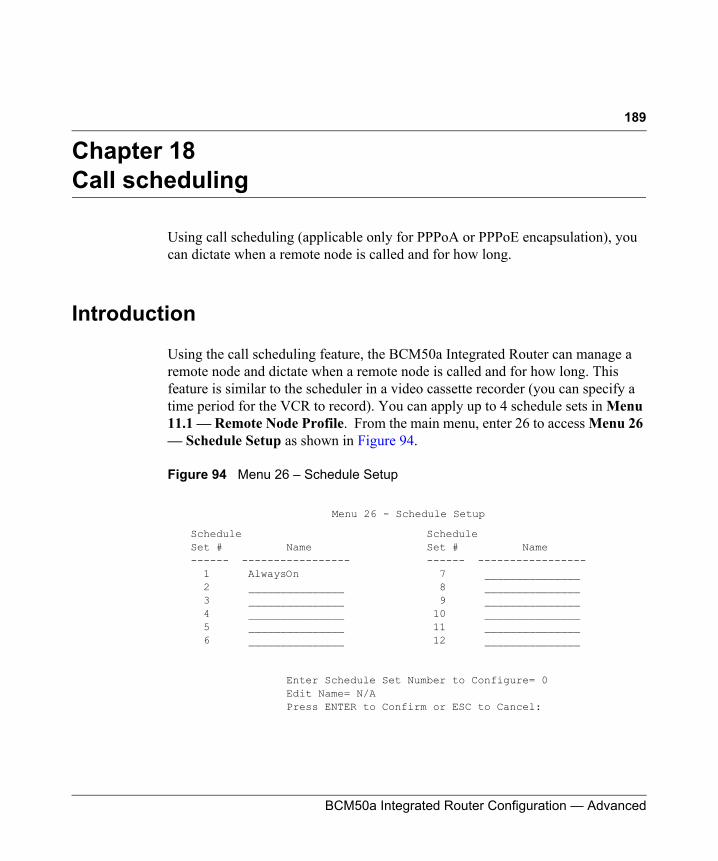
189
BCM50a Integrated Router Configuration — Advanced
Chapter 18Call scheduling
Using call scheduling (applicable only for PPPoA or PPPoE encapsulation), you can dictate when a remote node is called and for how long.
Introduction
Using the call scheduling feature, the BCM50a Integrated Router can manage a remote node and dictate when a remote node is called and for how long. This feature is similar to the scheduler in a video cassette recorder (you can specify a time period for the VCR to record). You can apply up to 4 schedule sets in Menu 11.1 — Remote Node Profile. From the main menu, enter 26 to access Menu 26 — Schedule Setup as shown in Figure 94.
Figure 94 Menu 26 – Schedule Setup
Menu 26 - Schedule Setup
Schedule Schedule Set # Name Set # Name ------ ----------------- ------ ----------------- 1 AlwaysOn 7 _______________ 2 _______________ 8 _______________ 3 _______________ 9 _______________ 4 _______________ 10 _______________ 5 _______________ 11 _______________ 6 _______________ 12 _______________
Enter Schedule Set Number to Configure= 0 Edit Name= N/A Press ENTER to Confirm or ESC to Cancel:
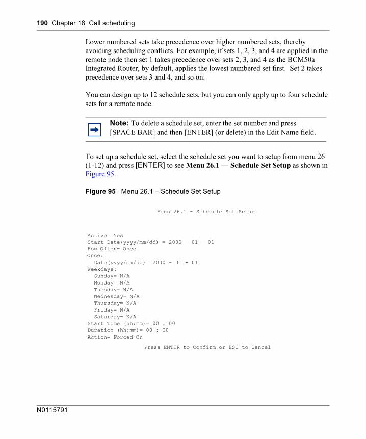
190 Chapter 18 Call scheduling
N0115791
Lower numbered sets take precedence over higher numbered sets, thereby avoiding scheduling conflicts. For example, if sets 1, 2, 3, and 4 are applied in the remote node then set 1 takes precedence over sets 2, 3, and 4 as the BCM50a Integrated Router, by default, applies the lowest numbered set first. Set 2 takes precedence over sets 3 and 4, and so on.
You can design up to 12 schedule sets, but you can only apply up to four schedule sets for a remote node.
To set up a schedule set, select the schedule set you want to setup from menu 26 (1-12) and press [ENTER] to see Menu 26.1 — Schedule Set Setup as shown in Figure 95.
Figure 95 Menu 26.1 – Schedule Set Setup
Note: To delete a schedule set, enter the set number and press [SPACE BAR] and then [ENTER] (or delete) in the Edit Name field.
Menu 26.1 - Schedule Set Setup
Active= YesStart Date(yyyy/mm/dd) = 2000 – 01 - 01How Often= OnceOnce: Date(yyyy/mm/dd)= 2000 – 01 - 01Weekdays: Sunday= N/A Monday= N/A Tuesday= N/A Wednesday= N/A Thursday= N/A Friday= N/A Saturday= N/AStart Time (hh:mm)= 00 : 00Duration (hh:mm)= 00 : 00Action= Forced On
Press ENTER to Confirm or ESC to Cancel
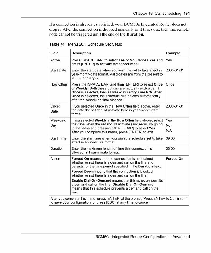
Chapter 18 Call scheduling 191
BCM50a Integrated Router Configuration — Advanced
If a connection is already established, your BCM50a Integrated Router does not drop it. After the connection is dropped manually or it times out, then that remote node cannot be triggered until the end of the Duration.
Table 41 Menu 26.1 Schedule Set Setup
Field Description Example
Active Press [SPACE BAR] to select Yes or No. Choose Yes and press [ENTER] to activate the schedule set.
Yes
Start Date Enter the start date when you wish the set to take effect in year-month-date format. Valid dates are from the present to 2036-February-5.
2000-01-01
How Often Press the [SPACE BAR] and then [ENTER] to select Once or Weekly. Both these options are mutually exclusive. If Once is selected, then all weekday settings are N/A. After Once is selected, the schedule rule deletes automatically after the scheduled time elapses.
Once
Once: Date
If you selected Once in the How Often field above, enter the date the set should activate here in year-month-date format.
2000-01-01
Weekday:Day
If you selected Weekly in the How Often field above, select the days when the set should activate (and recur) by going to that days and pressing [SPACE BAR] to select Yes. After you complete this menu, press [ENTER] to exit.
YesNoN/A
Start Time Enter the start time when you wish the schedule set to take effect in hour-minute format.
09:00
Duration Enter the maximum length of time this connection is allowed, in hour-minute format.
08:00
Action Forced On means that the connection is maintained whether or not there is a demand call on the line and persists for the time period specified in the Duration field.Forced Down means that the connection is blocked whether or not there is a demand call on the line. Enable Dial-On-Demand means that this schedule permits a demand call on the line. Disable Dial-On-Demand means that this schedule prevents a demand call on the line.
Forced On
After you complete this menu, press [ENTER] at the prompt “Press ENTER to Confirm…” to save your configuration, or press [ESC] at any time to cancel.
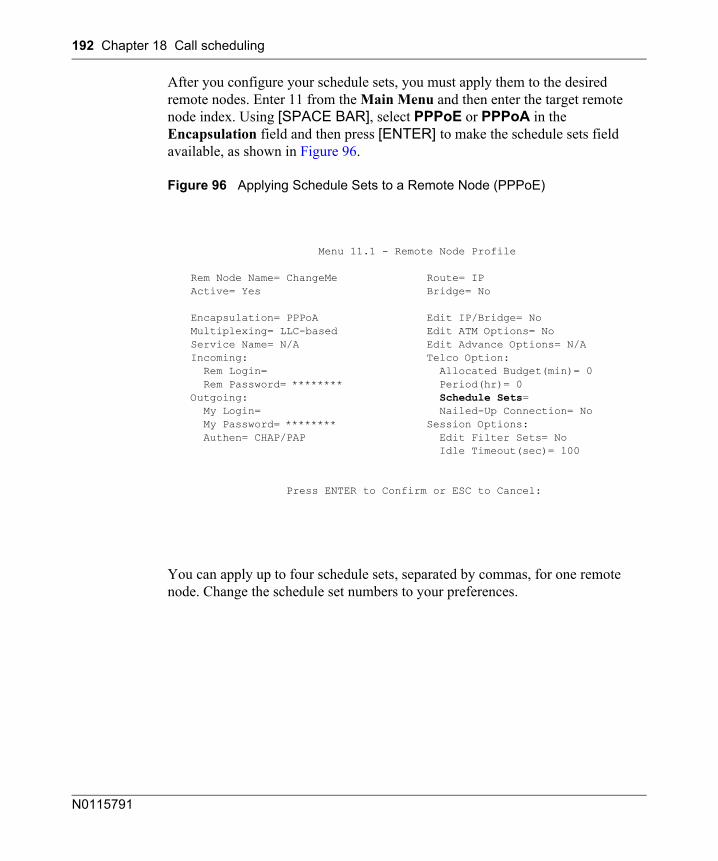
192 Chapter 18 Call scheduling
N0115791
After you configure your schedule sets, you must apply them to the desired remote nodes. Enter 11 from the Main Menu and then enter the target remote node index. Using [SPACE BAR], select PPPoE or PPPoA in the Encapsulation field and then press [ENTER] to make the schedule sets field available, as shown in Figure 96.
Figure 96 Applying Schedule Sets to a Remote Node (PPPoE)
You can apply up to four schedule sets, separated by commas, for one remote node. Change the schedule set numbers to your preferences.
Menu 11.1 - Remote Node Profile
Rem Node Name= ChangeMe Route= IP Active= Yes Bridge= No
Encapsulation= PPPoA Edit IP/Bridge= No Multiplexing= LLC-based Edit ATM Options= No Service Name= N/A Edit Advance Options= N/A Incoming: Telco Option: Rem Login= Allocated Budget(min)= 0 Rem Password= ******** Period(hr)= 0 Outgoing: Schedule Sets= My Login= Nailed-Up Connection= No My Password= ******** Session Options: Authen= CHAP/PAP Edit Filter Sets= No Idle Timeout(sec)= 100
Press ENTER to Confirm or ESC to Cancel:
193
BCM50a Integrated Router Configuration — Advanced
Appendix ASetting up your computer IP address
All computers must have a 10M or 100M Ethernet adapter card and TCP/IP installed.
Windows 95/98/Me/NT/2000/XP, and Macintosh OS 7 and later operating systems and all versions of UNIX/LINUX include the software components you need to install and use TCP/IP on your computer. Windows 3.1 requires the purchase of a third-party TCP/IP application package.
TCP/IP is already installed on computers using Windows NT/2000/XP, or Macintosh OS 7 and later operating systems.
After the appropriate TCP/IP components are installed, configure the TCP/IP settings in order to communicate with your network.
If you manually assign IP information instead of using dynamic assignment, make sure that your computers have IP addresses that place them in the same subnet as the BCM50a Integrated Router LAN port.
Windows 95/98/Me
Click Start, Settings, Control Panel and double-click the Network icon to open the Network window
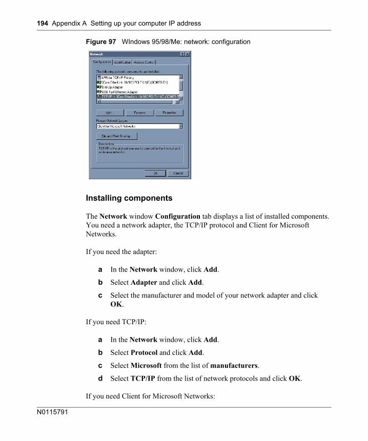
194 Appendix A Setting up your computer IP address
N0115791
Figure 97 WIndows 95/98/Me: network: configuration
Installing components
The Network window Configuration tab displays a list of installed components. You need a network adapter, the TCP/IP protocol and Client for Microsoft Networks.
If you need the adapter:
a In the Network window, click Add.
b Select Adapter and click Add.
c Select the manufacturer and model of your network adapter and click OK.
If you need TCP/IP:
a In the Network window, click Add.
b Select Protocol and click Add.
c Select Microsoft from the list of manufacturers.
d Select TCP/IP from the list of network protocols and click OK.
If you need Client for Microsoft Networks:
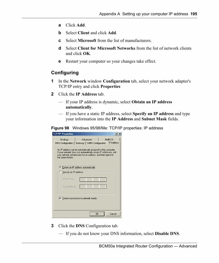
Appendix A Setting up your computer IP address 195
BCM50a Integrated Router Configuration — Advanced
a Click Add.
b Select Client and click Add.
c Select Microsoft from the list of manufacturers.
d Select Client for Microsoft Networks from the list of network clients and click OK.
e Restart your computer so your changes take effect.
Configuring 1 In the Network window Configuration tab, select your network adapter's
TCP/IP entry and click Properties
2 Click the IP Address tab.
— If your IP address is dynamic, select Obtain an IP address automatically.
— If you have a static IP address, select Specify an IP address and type your information into the IP Address and Subnet Mask fields.
Figure 98 Windows 95/98/Me: TCP/IP properties: IP address
3 Click the DNS Configuration tab.
— If you do not know your DNS information, select Disable DNS.
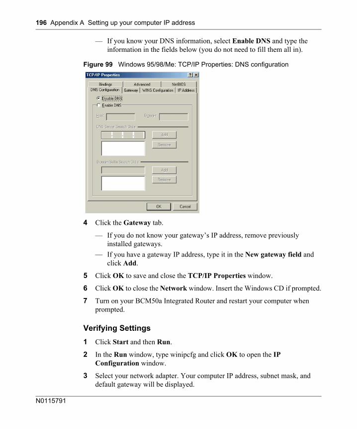
196 Appendix A Setting up your computer IP address
N0115791
— If you know your DNS information, select Enable DNS and type the information in the fields below (you do not need to fill them all in).
Figure 99 Windows 95/98/Me: TCP/IP Properties: DNS configuration
4 Click the Gateway tab.
— If you do not know your gateway’s IP address, remove previously installed gateways.
— If you have a gateway IP address, type it in the New gateway field and click Add.
5 Click OK to save and close the TCP/IP Properties window.
6 Click OK to close the Network window. Insert the Windows CD if prompted.
7 Turn on your BCM50a Integrated Router and restart your computer when prompted.
Verifying Settings1 Click Start and then Run.
2 In the Run window, type winipcfg and click OK to open the IP Configuration window.
3 Select your network adapter. Your computer IP address, subnet mask, and default gateway will be displayed.
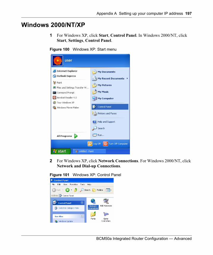
Appendix A Setting up your computer IP address 197
BCM50a Integrated Router Configuration — Advanced
Windows 2000/NT/XP1 For Windows XP, click Start, Control Panel. In Windows 2000/NT, click
Start, Settings, Control Panel.
Figure 100 Windows XP: Start menu
2 For Windows XP, click Network Connections. For Windows 2000/NT, click Network and Dial-up Connections.
Figure 101 Windows XP: Control Panel
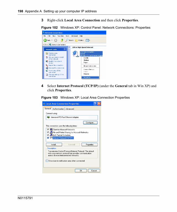
198 Appendix A Setting up your computer IP address
N0115791
3 Right-click Local Area Connection and then click Properties.
Figure 102 Windows XP: Control Panel: Network Connections: Properties
4 Select Internet Protocol (TCP/IP) (under the General tab in Win XP) and click Properties.
Figure 103 Windows XP: Local Area Connection Properties
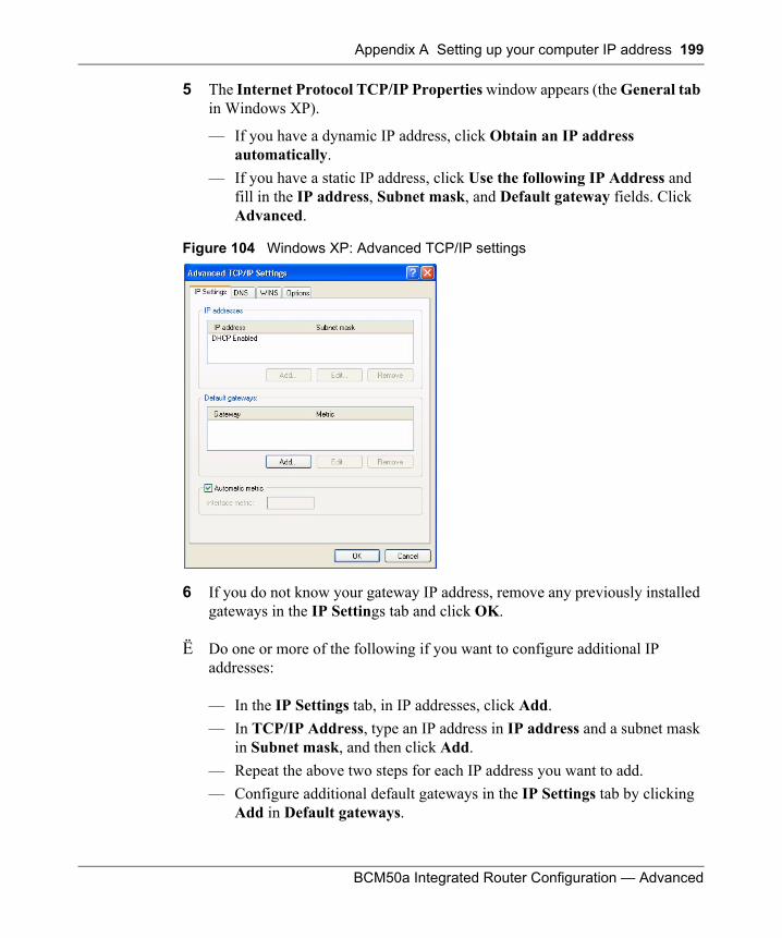
Appendix A Setting up your computer IP address 199
BCM50a Integrated Router Configuration — Advanced
5 The Internet Protocol TCP/IP Properties window appears (the General tab in Windows XP).
— If you have a dynamic IP address, click Obtain an IP address automatically.
— If you have a static IP address, click Use the following IP Address and fill in the IP address, Subnet mask, and Default gateway fields. Click Advanced.
Figure 104 Windows XP: Advanced TCP/IP settings
6 If you do not know your gateway IP address, remove any previously installed gateways in the IP Settings tab and click OK.
Ë Do one or more of the following if you want to configure additional IP addresses:
— In the IP Settings tab, in IP addresses, click Add.— In TCP/IP Address, type an IP address in IP address and a subnet mask
in Subnet mask, and then click Add.— Repeat the above two steps for each IP address you want to add.— Configure additional default gateways in the IP Settings tab by clicking
Add in Default gateways.
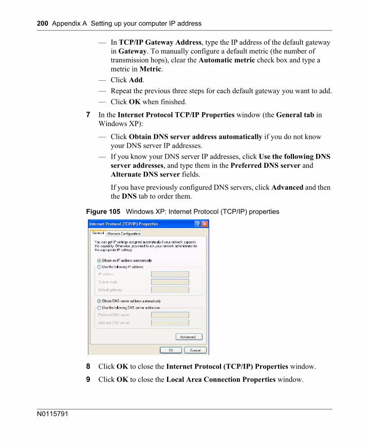
200 Appendix A Setting up your computer IP address
N0115791
— In TCP/IP Gateway Address, type the IP address of the default gateway in Gateway. To manually configure a default metric (the number of transmission hops), clear the Automatic metric check box and type a metric in Metric.
— Click Add. — Repeat the previous three steps for each default gateway you want to add.— Click OK when finished.
7 In the Internet Protocol TCP/IP Properties window (the General tab in Windows XP):
— Click Obtain DNS server address automatically if you do not know your DNS server IP addresses.
— If you know your DNS server IP addresses, click Use the following DNS server addresses, and type them in the Preferred DNS server and Alternate DNS server fields.
If you have previously configured DNS servers, click Advanced and then the DNS tab to order them.
Figure 105 Windows XP: Internet Protocol (TCP/IP) properties
8 Click OK to close the Internet Protocol (TCP/IP) Properties window.
9 Click OK to close the Local Area Connection Properties window.
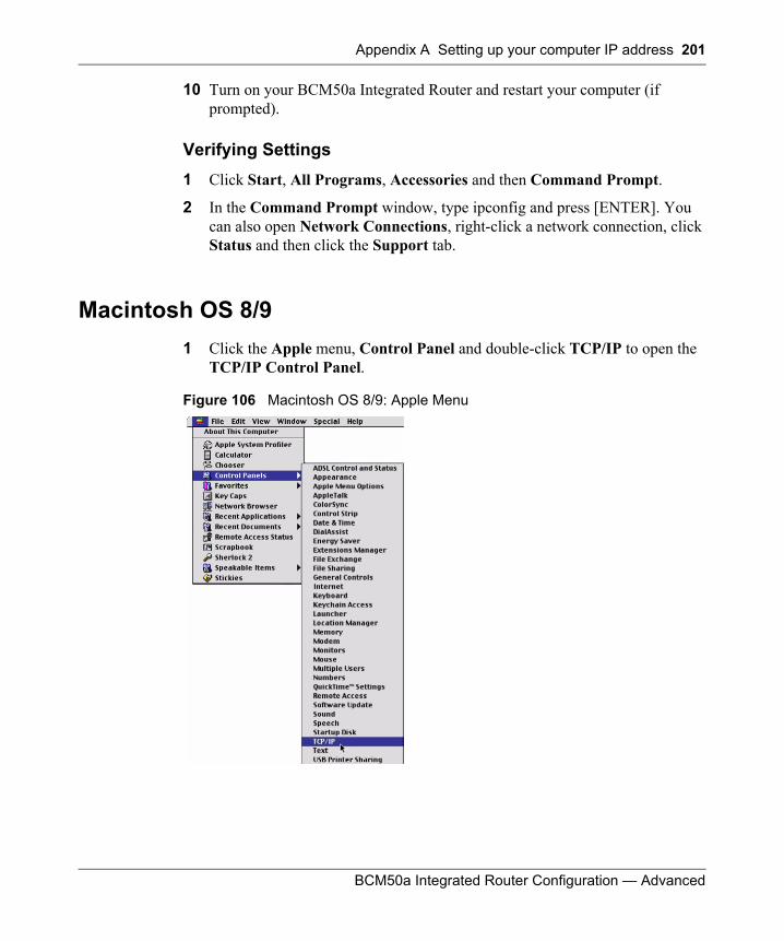
Appendix A Setting up your computer IP address 201
BCM50a Integrated Router Configuration — Advanced
10 Turn on your BCM50a Integrated Router and restart your computer (if prompted).
Verifying Settings1 Click Start, All Programs, Accessories and then Command Prompt.
2 In the Command Prompt window, type ipconfig and press [ENTER]. You can also open Network Connections, right-click a network connection, click Status and then click the Support tab.
Macintosh OS 8/9 1 Click the Apple menu, Control Panel and double-click TCP/IP to open the
TCP/IP Control Panel.
Figure 106 Macintosh OS 8/9: Apple Menu
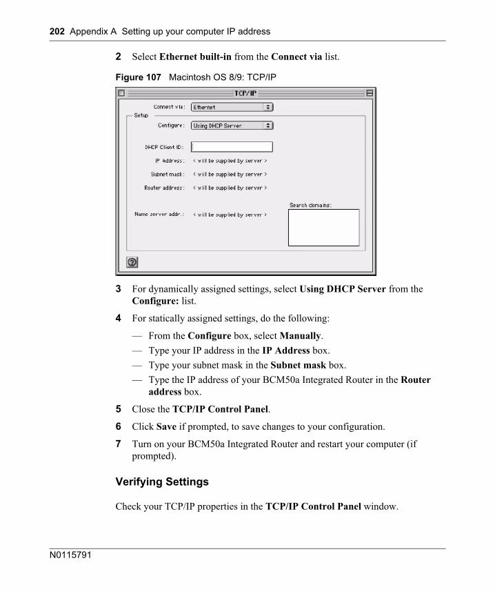
202 Appendix A Setting up your computer IP address
N0115791
2 Select Ethernet built-in from the Connect via list.
Figure 107 Macintosh OS 8/9: TCP/IP
3 For dynamically assigned settings, select Using DHCP Server from the Configure: list.
4 For statically assigned settings, do the following:
— From the Configure box, select Manually.— Type your IP address in the IP Address box.— Type your subnet mask in the Subnet mask box.— Type the IP address of your BCM50a Integrated Router in the Router
address box.
5 Close the TCP/IP Control Panel.
6 Click Save if prompted, to save changes to your configuration.
7 Turn on your BCM50a Integrated Router and restart your computer (if prompted).
Verifying Settings
Check your TCP/IP properties in the TCP/IP Control Panel window.
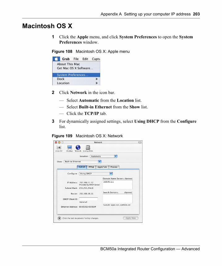
Appendix A Setting up your computer IP address 203
BCM50a Integrated Router Configuration — Advanced
Macintosh OS X1 Click the Apple menu, and click System Preferences to open the System
Preferences window.
Figure 108 Macintosh OS X: Apple menu
2 Click Network in the icon bar.
— Select Automatic from the Location list.— Select Built-in Ethernet from the Show list. — Click the TCP/IP tab.
3 For dynamically assigned settings, select Using DHCP from the Configure list.
Figure 109 Macintosh OS X: Network
204 Appendix A Setting up your computer IP address
N0115791
4 For statically assigned settings, do the following:
— From the Configure box, select Manually.— Type your IP address in the IP Address box.— Type your subnet mask in the Subnet mask box.— Type the IP address of your BCM50a Integrated Router in the Router
address box.
5 Click Apply Now and close the window.
6 Turn on your BCM50a Integrated Router and restart your computer (if prompted).
Verifying settings
Check your TCP/IP properties in the Network window.
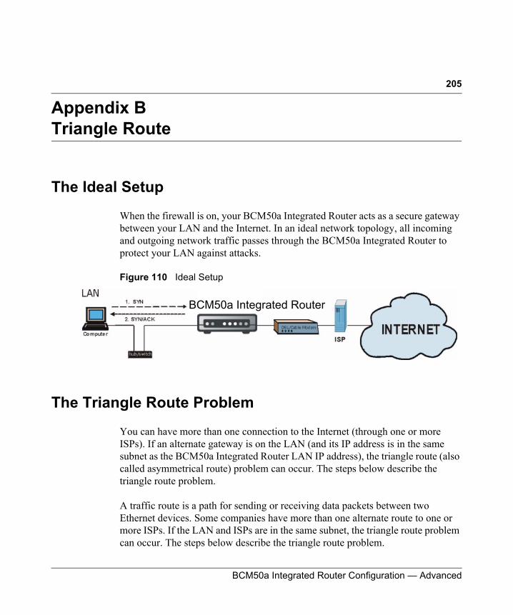
205
BCM50a Integrated Router Configuration — Advanced
Appendix BTriangle Route
The Ideal Setup
When the firewall is on, your BCM50a Integrated Router acts as a secure gateway between your LAN and the Internet. In an ideal network topology, all incoming and outgoing network traffic passes through the BCM50a Integrated Router to protect your LAN against attacks.
Figure 110 Ideal Setup
The Triangle Route Problem
You can have more than one connection to the Internet (through one or more ISPs). If an alternate gateway is on the LAN (and its IP address is in the same subnet as the BCM50a Integrated Router LAN IP address), the triangle route (also called asymmetrical route) problem can occur. The steps below describe the triangle route problem.
A traffic route is a path for sending or receiving data packets between two Ethernet devices. Some companies have more than one alternate route to one or more ISPs. If the LAN and ISPs are in the same subnet, the triangle route problem can occur. The steps below describe the triangle route problem.
BCM50a Integrated Router
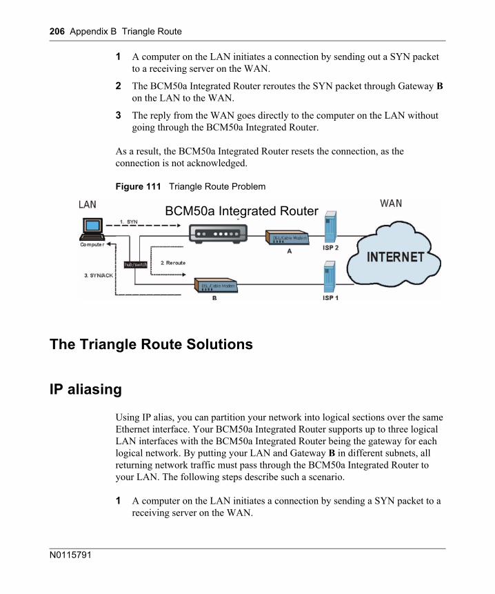
206 Appendix B Triangle Route
N0115791
1 A computer on the LAN initiates a connection by sending out a SYN packet to a receiving server on the WAN.
2 The BCM50a Integrated Router reroutes the SYN packet through Gateway B on the LAN to the WAN.
3 The reply from the WAN goes directly to the computer on the LAN without going through the BCM50a Integrated Router.
As a result, the BCM50a Integrated Router resets the connection, as the connection is not acknowledged.
Figure 111 Triangle Route Problem
The Triangle Route Solutions
IP aliasing
Using IP alias, you can partition your network into logical sections over the same Ethernet interface. Your BCM50a Integrated Router supports up to three logical LAN interfaces with the BCM50a Integrated Router being the gateway for each logical network. By putting your LAN and Gateway B in different subnets, all returning network traffic must pass through the BCM50a Integrated Router to your LAN. The following steps describe such a scenario.
1 A computer on the LAN initiates a connection by sending a SYN packet to a receiving server on the WAN.
BCM50a Integrated Router
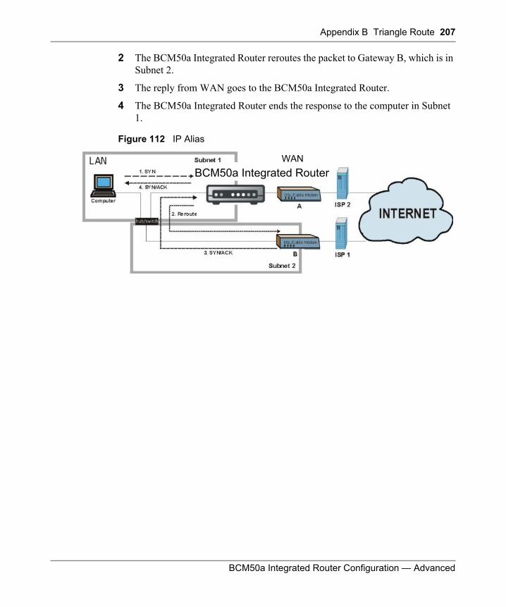
Appendix B Triangle Route 207
BCM50a Integrated Router Configuration — Advanced
2 The BCM50a Integrated Router reroutes the packet to Gateway B, which is in Subnet 2.
3 The reply from WAN goes to the BCM50a Integrated Router.
4 The BCM50a Integrated Router ends the response to the computer in Subnet 1.
Figure 112 IP Alias
BCM50a Integrated RouterWAN

208 Appendix B Triangle Route
N0115791
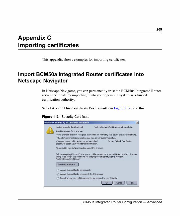
209
BCM50a Integrated Router Configuration — Advanced
Appendix CImporting certificates
This appendix shows examples for importing certificates.
Import BCM50a Integrated Router certificates into Netscape Navigator
In Netscape Navigator, you can permanently trust the BCM50a Integrated Router server certificate by importing it into your operating system as a trusted certification authority.
Select Accept This Certificate Permanently in Figure 113 to do this.
Figure 113 Security Certificate
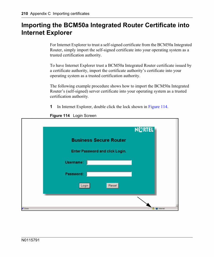
210 Appendix C Importing certificates
N0115791
Importing the BCM50a Integrated Router Certificate into Internet Explorer
For Internet Explorer to trust a self-signed certificate from the BCM50a Integrated Router, simply import the self-signed certificate into your operating system as a trusted certification authority.
To have Internet Explorer trust a BCM50a Integrated Router certificate issued by a certificate authority, import the certificate authority’s certificate into your operating system as a trusted certification authority.
The following example procedure shows how to import the BCM50a Integrated Router’s (self-signed) server certificate into your operating system as a trusted certification authority.
1 In Internet Explorer, double click the lock shown in Figure 114.
Figure 114 Login Screen
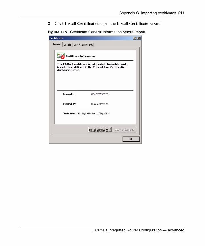
Appendix C Importing certificates 211
BCM50a Integrated Router Configuration — Advanced
2 Click Install Certificate to open the Install Certificate wizard.
Figure 115 Certificate General Information before Import
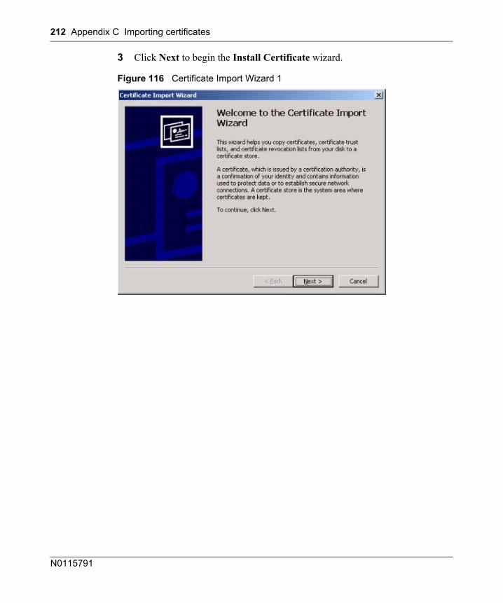
212 Appendix C Importing certificates
N0115791
3 Click Next to begin the Install Certificate wizard.
Figure 116 Certificate Import Wizard 1
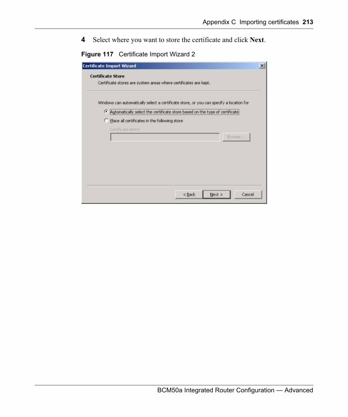
Appendix C Importing certificates 213
BCM50a Integrated Router Configuration — Advanced
4 Select where you want to store the certificate and click Next.
Figure 117 Certificate Import Wizard 2
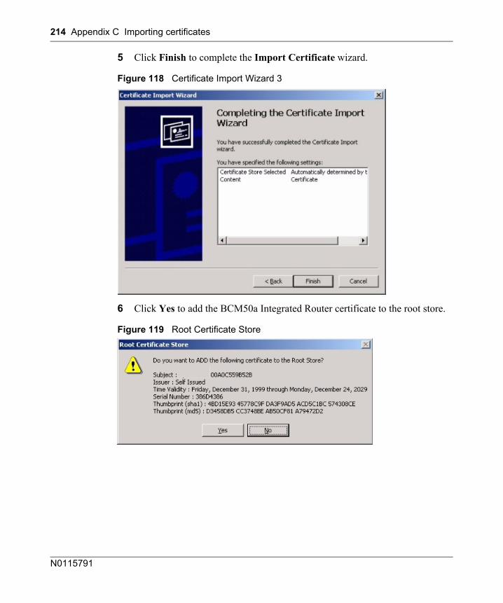
214 Appendix C Importing certificates
N0115791
5 Click Finish to complete the Import Certificate wizard.
Figure 118 Certificate Import Wizard 3
6 Click Yes to add the BCM50a Integrated Router certificate to the root store.
Figure 119 Root Certificate Store
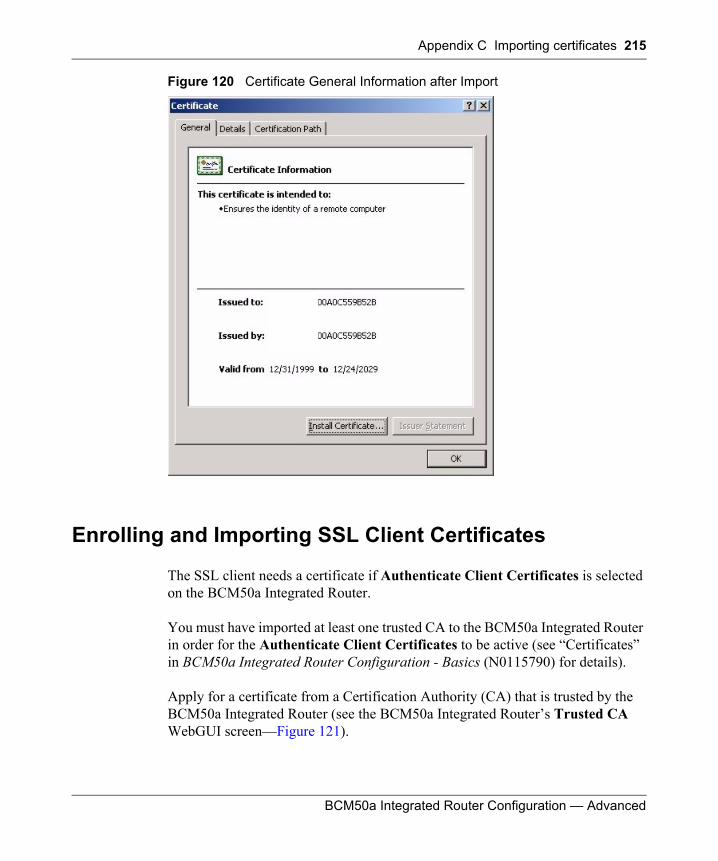
Appendix C Importing certificates 215
BCM50a Integrated Router Configuration — Advanced
Figure 120 Certificate General Information after Import
Enrolling and Importing SSL Client Certificates
The SSL client needs a certificate if Authenticate Client Certificates is selected on the BCM50a Integrated Router.
You must have imported at least one trusted CA to the BCM50a Integrated Router in order for the Authenticate Client Certificates to be active (see “Certificates” in BCM50a Integrated Router Configuration - Basics (N0115790) for details).
Apply for a certificate from a Certification Authority (CA) that is trusted by the BCM50a Integrated Router (see the BCM50a Integrated Router’s Trusted CA WebGUI screen—Figure 121).
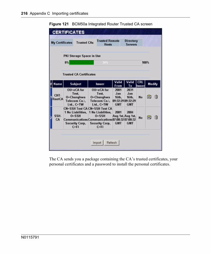
216 Appendix C Importing certificates
N0115791
Figure 121 BCM50a Integrated Router Trusted CA screen
The CA sends you a package containing the CA’s trusted certificates, your personal certificates and a password to install the personal certificates.
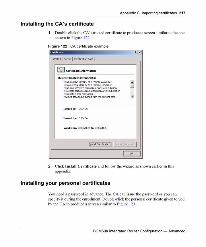
Appendix C Importing certificates 217
BCM50a Integrated Router Configuration — Advanced
Installing the CA’s certificate1 Double click the CA’s trusted certificate to produce a screen similar to the one
shown in Figure 122.
Figure 122 CA certificate example
2 Click Install Certificate and follow the wizard as shown earlier in this appendix.
Installing your personal certificates
You need a password in advance. The CA can issue the password or you can specify it during the enrollment. Double-click the personal certificate given to you by the CA to produce a screen similar to Figure 123
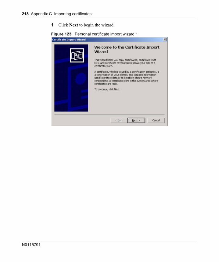
218 Appendix C Importing certificates
N0115791
1 Click Next to begin the wizard.
Figure 123 Personal certificate import wizard 1
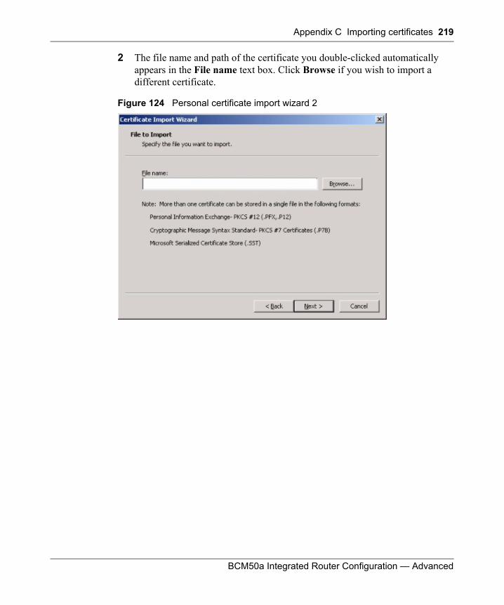
Appendix C Importing certificates 219
BCM50a Integrated Router Configuration — Advanced
2 The file name and path of the certificate you double-clicked automatically appears in the File name text box. Click Browse if you wish to import a different certificate.
Figure 124 Personal certificate import wizard 2
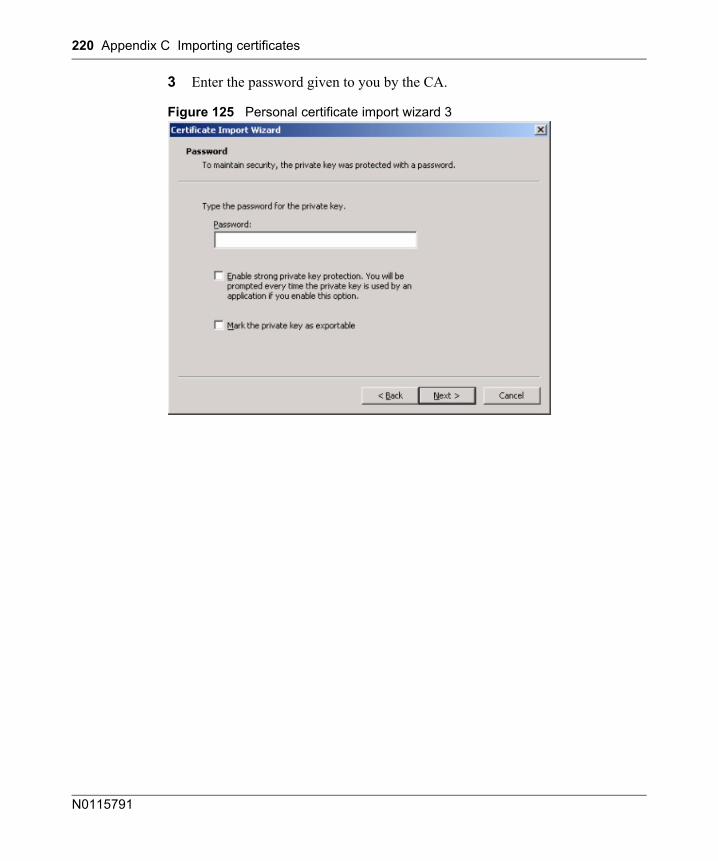
220 Appendix C Importing certificates
N0115791
3 Enter the password given to you by the CA.
Figure 125 Personal certificate import wizard 3
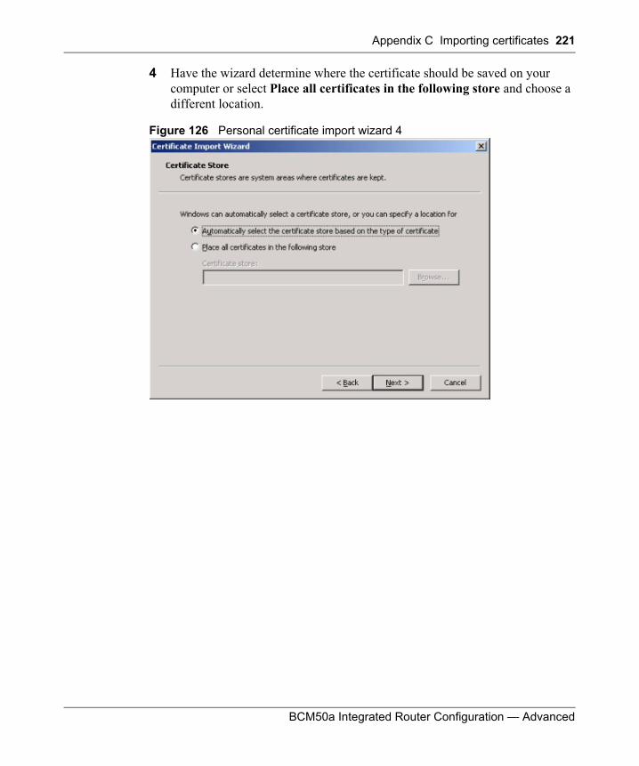
Appendix C Importing certificates 221
BCM50a Integrated Router Configuration — Advanced
4 Have the wizard determine where the certificate should be saved on your computer or select Place all certificates in the following store and choose a different location.
Figure 126 Personal certificate import wizard 4
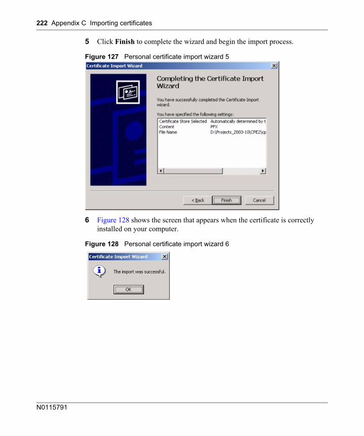
222 Appendix C Importing certificates
N0115791
5 Click Finish to complete the wizard and begin the import process.
Figure 127 Personal certificate import wizard 5
6 Figure 128 shows the screen that appears when the certificate is correctly installed on your computer.
Figure 128 Personal certificate import wizard 6
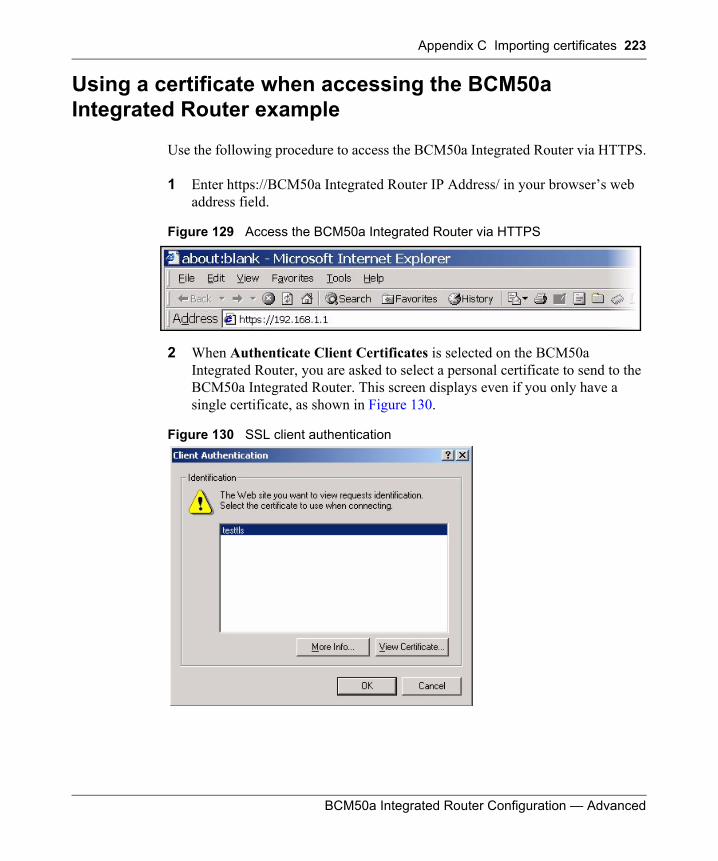
Appendix C Importing certificates 223
BCM50a Integrated Router Configuration — Advanced
Using a certificate when accessing the BCM50a Integrated Router example
Use the following procedure to access the BCM50a Integrated Router via HTTPS.
1 Enter https://BCM50a Integrated Router IP Address/ in your browser’s web address field.
Figure 129 Access the BCM50a Integrated Router via HTTPS
2 When Authenticate Client Certificates is selected on the BCM50a Integrated Router, you are asked to select a personal certificate to send to the BCM50a Integrated Router. This screen displays even if you only have a single certificate, as shown in Figure 130.
Figure 130 SSL client authentication
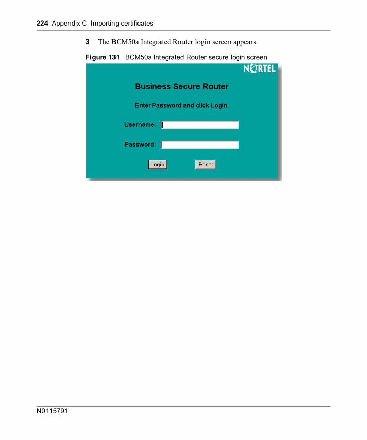
224 Appendix C Importing certificates
N0115791
3 The BCM50a Integrated Router login screen appears.
Figure 131 BCM50a Integrated Router secure login screen
225
BCM50a Integrated Router Configuration — Advanced
Appendix DPPPoE
PPPoE in action
An ADSL modem bridges a PPP session over Ethernet (PPP over Ethernet, RFC 2516) from your PC to an ATM PVC (Permanent Virtual Circuit), which connects to a DSL Access Concentrator where the PPP session terminates (see Figure 132). One PVC can support any number of PPP sessions from your LAN. PPPoE provides access control and billing functionality in a manner similar to dial-up services using PPP.
Benefits of PPPoE
PPPoE offers the following benefits:
• It provides you with a familiar dial-up networking (DUN) user interface.• It lessens the burden on the carriers of provisioning virtual circuits all the way
to the ISP on multiple switches for thousands of users. For GSTN (PSTN and ISDN), the switching fabric is already in place.
• It allows the ISP to use the existing dial-up model to authenticate and (optionally) to provide differentiated services.
Traditional dial-up scenario
Figure 132 depicts a typical hardware configuration in which the PCs use traditional dial-up networking.
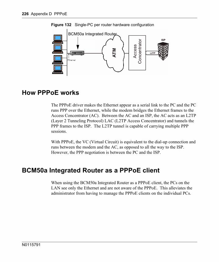
226 Appendix D PPPoE
N0115791
Figure 132 Single-PC per router hardware configuration
How PPPoE works
The PPPoE driver makes the Ethernet appear as a serial link to the PC and the PC runs PPP over the Ethernet, while the modem bridges the Ethernet frames to the Access Concentrator (AC). Between the AC and an ISP, the AC acts as an L2TP (Layer 2 Tunneling Protocol) LAC (L2TP Access Concentrator) and tunnels the PPP frames to the ISP. The L2TP tunnel is capable of carrying multiple PPP sessions.
With PPPoE, the VC (Virtual Circuit) is equivalent to the dial-up connection and runs between the modem and the AC, as opposed to all the way to the ISP. However, the PPP negotiation is between the PC and the ISP.
BCM50a Integrated Router as a PPPoE client
When using the BCM50a Integrated Router as a PPPoE client, the PCs on the LAN see only the Ethernet and are not aware of the PPPoE. This alleviates the administrator from having to manage the PPPoE clients on the individual PCs.
BCM50a Integrated Router
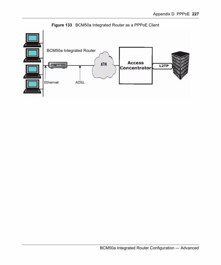
Appendix D PPPoE 227
BCM50a Integrated Router Configuration — Advanced
Figure 133 BCM50a Integrated Router as a PPPoE Client
BCM50a Integrated RouterBCM50a Integrated Router

228 Appendix D PPPoE
N0115791
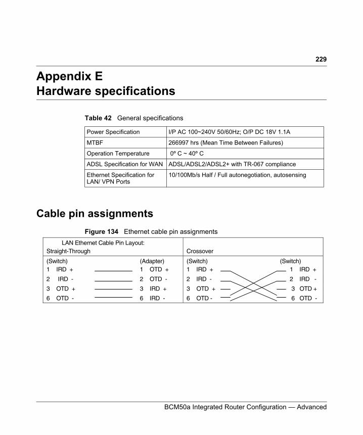
229
BCM50a Integrated Router Configuration — Advanced
Appendix EHardware specifications
Cable pin assignmentsFigure 134 Ethernet cable pin assignments
Table 42 General specifications
Power Specification I/P AC 100~240V 50/60Hz; O/P DC 18V 1.1A
MTBF 266997 hrs (Mean Time Between Failures)
Operation Temperature 0º C ~ 40º C
ADSL Specification for WAN ADSL/ADSL2/ADSL2+ with TR-067 compliance
Ethernet Specification for LAN/ VPN Ports
10/100Mb/s Half / Full autonegotiation, autosensing
WAN/LAN Ethernet Cable Pin Layout: Straight-Through
Crossover
(Switch) 1 IRD +
(Adapter) 1 OTD +
(Switch) 1 IRD +
(Switch) 1 IRD +
2 IRD - 2 OTD - 2 IRD - 2 IRD -
3 OTD + 3 IRD + 3 OTD + 3 OTD +
6 OTD - 6 IRD - 6 OTD - 6 OTD -

230 Appendix E Hardware specifications
N0115791
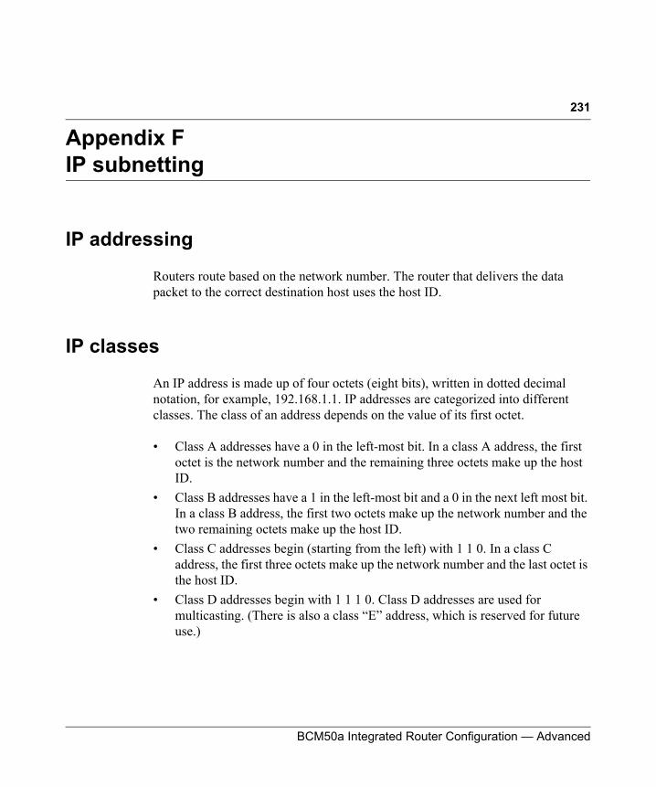
231
BCM50a Integrated Router Configuration — Advanced
Appendix FIP subnetting
IP addressing
Routers route based on the network number. The router that delivers the data packet to the correct destination host uses the host ID.
IP classes
An IP address is made up of four octets (eight bits), written in dotted decimal notation, for example, 192.168.1.1. IP addresses are categorized into different classes. The class of an address depends on the value of its first octet.
• Class A addresses have a 0 in the left-most bit. In a class A address, the first octet is the network number and the remaining three octets make up the host ID.
• Class B addresses have a 1 in the left-most bit and a 0 in the next left most bit. In a class B address, the first two octets make up the network number and the two remaining octets make up the host ID.
• Class C addresses begin (starting from the left) with 1 1 0. In a class C address, the first three octets make up the network number and the last octet is the host ID.
• Class D addresses begin with 1 1 1 0. Class D addresses are used for multicasting. (There is also a class “E” address, which is reserved for future use.)
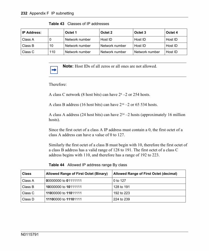
232 Appendix F IP subnetting
N0115791
Therefore:
A class C network (8 host bits) can have 28 –2 or 254 hosts.
A class B address (16 host bits) can have 216 –2 or 65 534 hosts.
A class A address (24 host bits) can have 224 –2 hosts (approximately 16 million hosts).
Since the first octet of a class A IP address must contain a 0, the first octet of a class A address can have a value of 0 to 127.
Similarly the first octet of a class B must begin with 10, therefore the first octet of a class B address has a valid range of 128 to 191. The first octet of a class C address begins with 110, and therefore has a range of 192 to 223.
Table 43 Classes of IP addresses
IP Address: Octet 1 Octet 2 Octet 3 Octet 4
Class A 0 Network number Host ID Host ID Host ID
Class B 10 Network number Network number Host ID Host ID
Class C 110 Network number Network number Network number Host ID
Note: Host IDs of all zeros or all ones are not allowed.
Table 44 Allowed IP address range By class
Class Allowed Range of First Octet (Binary) Allowed Range of First Octet (decimal)
Class A 00000000 to 01111111 0 to 127
Class B 10000000 to 10111111 128 to 191
Class C 11000000 to 11011111 192 to 223
Class D 11100000 to 11101111 224 to 239
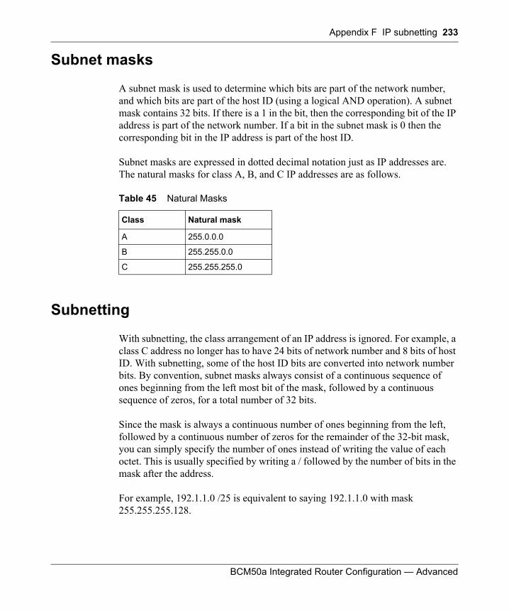
Appendix F IP subnetting 233
BCM50a Integrated Router Configuration — Advanced
Subnet masks
A subnet mask is used to determine which bits are part of the network number, and which bits are part of the host ID (using a logical AND operation). A subnet mask contains 32 bits. If there is a 1 in the bit, then the corresponding bit of the IP address is part of the network number. If a bit in the subnet mask is 0 then the corresponding bit in the IP address is part of the host ID.
Subnet masks are expressed in dotted decimal notation just as IP addresses are. The natural masks for class A, B, and C IP addresses are as follows.
Subnetting
With subnetting, the class arrangement of an IP address is ignored. For example, a class C address no longer has to have 24 bits of network number and 8 bits of host ID. With subnetting, some of the host ID bits are converted into network number bits. By convention, subnet masks always consist of a continuous sequence of ones beginning from the left most bit of the mask, followed by a continuous sequence of zeros, for a total number of 32 bits.
Since the mask is always a continuous number of ones beginning from the left, followed by a continuous number of zeros for the remainder of the 32-bit mask, you can simply specify the number of ones instead of writing the value of each octet. This is usually specified by writing a / followed by the number of bits in the mask after the address.
For example, 192.1.1.0 /25 is equivalent to saying 192.1.1.0 with mask 255.255.255.128.
Table 45 Natural Masks
Class Natural mask
A 255.0.0.0
B 255.255.0.0
C 255.255.255.0
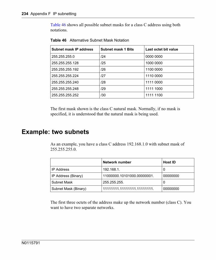
234 Appendix F IP subnetting
N0115791
Table 46 shows all possible subnet masks for a class C address using both notations.
The first mask shown is the class C natural mask. Normally, if no mask is specified, it is understood that the natural mask is being used.
Example: two subnets
As an example, you have a class C address 192.168.1.0 with subnet mask of 255.255.255.0.
The first three octets of the address make up the network number (class C). You want to have two separate networks.
Table 46 Alternative Subnet Mask Notation
Subnet mask IP address Subnet mask 1 Bits Last octet bit value
255.255.255.0 /24 0000 0000
255.255.255.128 /25 1000 0000
255.255.255.192 /26 1100 0000
255.255.255.224 /27 1110 0000
255.255.255.240 /28 1111 0000
255.255.255.248 /29 1111 1000
255.255.255.252 /30 1111 1100
Network number Host ID
IP Address 192.168.1. 0
IP Address (Binary) 11000000.10101000.00000001. 00000000
Subnet Mask 255.255.255. 0
Subnet Mask (Binary) 11111111.11111111.11111111. 00000000
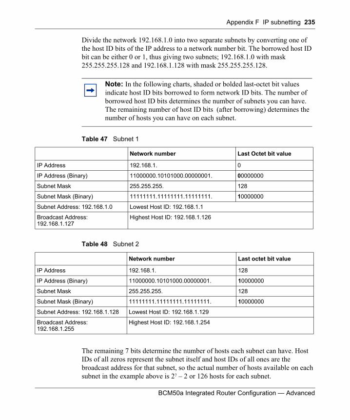
Appendix F IP subnetting 235
BCM50a Integrated Router Configuration — Advanced
Divide the network 192.168.1.0 into two separate subnets by converting one of the host ID bits of the IP address to a network number bit. The borrowed host ID bit can be either 0 or 1, thus giving two subnets; 192.168.1.0 with mask 255.255.255.128 and 192.168.1.128 with mask 255.255.255.128.
The remaining 7 bits determine the number of hosts each subnet can have. Host IDs of all zeros represent the subnet itself and host IDs of all ones are the broadcast address for that subnet, so the actual number of hosts available on each subnet in the example above is 27 – 2 or 126 hosts for each subnet.
Note: In the following charts, shaded or bolded last-octet bit values indicate host ID bits borrowed to form network ID bits. The number of borrowed host ID bits determines the number of subnets you can have. The remaining number of host ID bits (after borrowing) determines the number of hosts you can have on each subnet.
Table 47 Subnet 1
Network number Last Octet bit value
IP Address 192.168.1. 0
IP Address (Binary) 11000000.10101000.00000001. 00000000
Subnet Mask 255.255.255. 128
Subnet Mask (Binary) 11111111.11111111.11111111. 10000000
Subnet Address: 192.168.1.0 Lowest Host ID: 192.168.1.1
Broadcast Address: 192.168.1.127
Highest Host ID: 192.168.1.126
Table 48 Subnet 2
Network number Last octet bit value
IP Address 192.168.1. 128
IP Address (Binary) 11000000.10101000.00000001. 10000000
Subnet Mask 255.255.255. 128
Subnet Mask (Binary) 11111111.11111111.11111111. 10000000
Subnet Address: 192.168.1.128 Lowest Host ID: 192.168.1.129
Broadcast Address: 192.168.1.255
Highest Host ID: 192.168.1.254
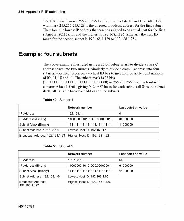
236 Appendix F IP subnetting
N0115791
192.168.1.0 with mask 255.255.255.128 is the subnet itself, and 192.168.1.127 with mask 255.255.255.128 is the directed broadcast address for the first subnet. Therefore, the lowest IP address that can be assigned to an actual host for the first subnet is 192.168.1.1 and the highest is 192.168.1.126. Similarly the host ID range for the second subnet is 192.168.1.129 to 192.168.1.254.
Example: four subnets
The above example illustrated using a 25-bit subnet mask to divide a class C address space into two subnets. Similarly to divide a class C address into four subnets, you need to borrow two host ID bits to give four possible combinations of 00, 01, 10 and 11. The subnet mask is 26 bits (11111111.11111111.11111111.11000000) or 255.255.255.192. Each subnet contains 6 host ID bits, giving 26-2 or 62 hosts for each subnet (all 0s is the subnet itself, all 1s is the broadcast address on the subnet).
Table 49 Subnet 1
Network number Last octet bit value
IP Address 192.168.1. 0
IP Address (Binary) 11000000.10101000.00000001. 00000000
Subnet Mask (Binary) 11111111.11111111.11111111. 11000000
Subnet Address: 192.168.1.0 Lowest Host ID: 192.168.1.1
Broadcast Address: 192.168.1.63 Highest Host ID: 192.168.1.62
Table 50 Subnet 2
Network number Last octet bit value
IP Address 192.168.1. 64
IP Address (Binary) 11000000.10101000.00000001. 01000000
Subnet Mask (Binary) 11111111.11111111.11111111. 11000000
Subnet Address: 192.168.1.64 Lowest Host ID: 192.168.1.65
Broadcast Address: 192.168.1.127
Highest Host ID: 192.168.1.126
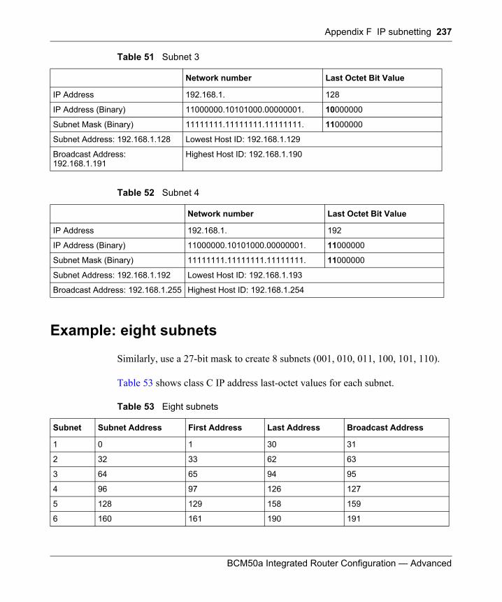
Appendix F IP subnetting 237
BCM50a Integrated Router Configuration — Advanced
Example: eight subnets
Similarly, use a 27-bit mask to create 8 subnets (001, 010, 011, 100, 101, 110).
Table 53 shows class C IP address last-octet values for each subnet.
Table 51 Subnet 3
Network number Last Octet Bit Value
IP Address 192.168.1. 128
IP Address (Binary) 11000000.10101000.00000001. 10000000
Subnet Mask (Binary) 11111111.11111111.11111111. 11000000
Subnet Address: 192.168.1.128 Lowest Host ID: 192.168.1.129
Broadcast Address: 192.168.1.191
Highest Host ID: 192.168.1.190
Table 52 Subnet 4
Network number Last Octet Bit Value
IP Address 192.168.1. 192
IP Address (Binary) 11000000.10101000.00000001. 11000000
Subnet Mask (Binary) 11111111.11111111.11111111. 11000000
Subnet Address: 192.168.1.192 Lowest Host ID: 192.168.1.193
Broadcast Address: 192.168.1.255 Highest Host ID: 192.168.1.254
Table 53 Eight subnets
Subnet Subnet Address First Address Last Address Broadcast Address
1 0 1 30 31
2 32 33 62 63
3 64 65 94 95
4 96 97 126 127
5 128 129 158 159
6 160 161 190 191
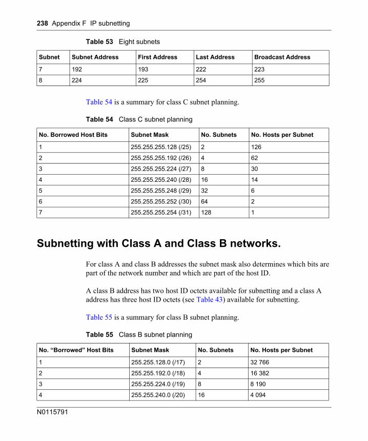
238 Appendix F IP subnetting
N0115791
Table 54 is a summary for class C subnet planning.
Subnetting with Class A and Class B networks.
For class A and class B addresses the subnet mask also determines which bits are part of the network number and which are part of the host ID.
A class B address has two host ID octets available for subnetting and a class A address has three host ID octets (see Table 43) available for subnetting.
Table 55 is a summary for class B subnet planning.
7 192 193 222 223
8 224 225 254 255
Table 54 Class C subnet planning
No. Borrowed Host Bits Subnet Mask No. Subnets No. Hosts per Subnet
1 255.255.255.128 (/25) 2 126
2 255.255.255.192 (/26) 4 62
3 255.255.255.224 (/27) 8 30
4 255.255.255.240 (/28) 16 14
5 255.255.255.248 (/29) 32 6
6 255.255.255.252 (/30) 64 2
7 255.255.255.254 (/31) 128 1
Table 55 Class B subnet planning
No. “Borrowed” Host Bits Subnet Mask No. Subnets No. Hosts per Subnet
1 255.255.128.0 (/17) 2 32 766
2 255.255.192.0 (/18) 4 16 382
3 255.255.224.0 (/19) 8 8 190
4 255.255.240.0 (/20) 16 4 094
Table 53 Eight subnets
Subnet Subnet Address First Address Last Address Broadcast Address
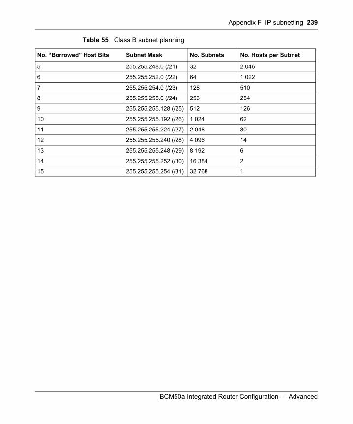
Appendix F IP subnetting 239
BCM50a Integrated Router Configuration — Advanced
5 255.255.248.0 (/21) 32 2 046
6 255.255.252.0 (/22) 64 1 022
7 255.255.254.0 (/23) 128 510
8 255.255.255.0 (/24) 256 254
9 255.255.255.128 (/25) 512 126
10 255.255.255.192 (/26) 1 024 62
11 255.255.255.224 (/27) 2 048 30
12 255.255.255.240 (/28) 4 096 14
13 255.255.255.248 (/29) 8 192 6
14 255.255.255.252 (/30) 16 384 2
15 255.255.255.254 (/31) 32 768 1
Table 55 Class B subnet planning
No. “Borrowed” Host Bits Subnet Mask No. Subnets No. Hosts per Subnet

240 Appendix F IP subnetting
N0115791
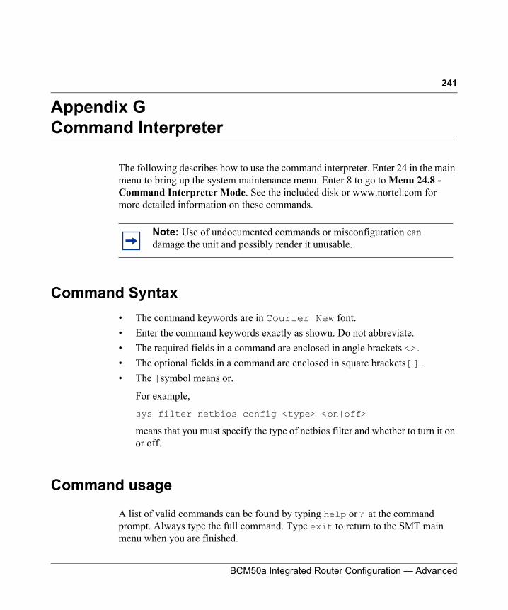
241
BCM50a Integrated Router Configuration — Advanced
Appendix GCommand Interpreter
The following describes how to use the command interpreter. Enter 24 in the main menu to bring up the system maintenance menu. Enter 8 to go to Menu 24.8 - Command Interpreter Mode. See the included disk or www.nortel.com for more detailed information on these commands.
Command Syntax• The command keywords are in Courier New font.• Enter the command keywords exactly as shown. Do not abbreviate.• The required fields in a command are enclosed in angle brackets <>. • The optional fields in a command are enclosed in square brackets [].• The |symbol means or.
For example,
sys filter netbios config <type> <on|off>
means that you must specify the type of netbios filter and whether to turn it on or off.
Command usage
A list of valid commands can be found by typing help or ? at the command prompt. Always type the full command. Type exit to return to the SMT main menu when you are finished.
Note: Use of undocumented commands or misconfiguration can damage the unit and possibly render it unusable.
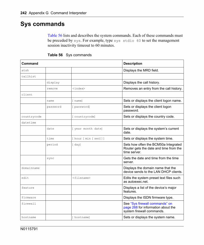
242 Appendix G Command Interpreter
N0115791
Sys commands
Table 56 lists and describes the system commands. Each of these commands must be preceded by sys. For example, type sys stdio 60 to set the management session inactivity timeout to 60 minutes.
Table 56 Sys commands
Command Description
atsh Displays the MRD field.
callhist
display Displays the call history.
remove <index> Removes an entry from the call history.
client
name [name] Sets or displays the client logon name.
password [password] Sets or displays the client logon password.
countrycode [countrycode] Sets or displays the country code.
datetime
date [year month date] Sets or displays the system’s current date.
time [hour [min [sec]]] Sets or displays the system time.
period [day] Sets how often the BCM50a Integrated Router gets the date and time from the time server.
sync Gets the date and time from the time server.
domainname Displays the domain name that the device sends to the LAN DHCP clients.
edit <filename> Edits the system preset text files such as autoexec.net.
feature Displays a list of the device’s major features.
firmware Displays the ISDN firmware type.
firewall See “Sys firewall commands” on page 268 for information about the system firewall commands.
hostname [hostname] Sets or displays the system name.
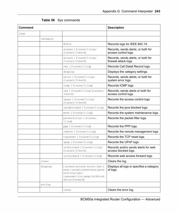
Appendix G Command Interpreter 243
BCM50a Integrated Router Configuration — Advanced
logs
category
8021x Records logs for IEEE 802.1X.
access [0:none/1:log/2:alert/3:both]
Records, sends alerts, or both for access control logs.
attack [0:none/1:log/2:alert/3:both]
Records, sends alerts, or both for firewall attack logs.
cdr [0:none/1:log] Records Call Detail Record logs.
display Displays the category settings.
error [0:none/1:log/2:alert/3:both]
Records, sends alerts, or both for system error logs.
icmp [0:none/1:log] Records ICMP logs.
ike [0:none/1:log/2:alert/3:both]
Records, sends alerts or both for access control logs.
ipsec [0:none/1:log/2:alert/3:both]
Records the access control logs
javablocked [0:none/1:log] Records the java blocked logs.
mten [0:none/1:log] Records the system maintenance logs.
packetfilter [0:none/1:log]
Records the packet filter logs.
ppp [0:none/1:log] Records the PPP logs.
remote [0:none/1:log] Records the remote management logs.
tcpreset [0:none/1:log] Records the TCP reset logs.
upnp [0:none/1:log] Records the UPnP logs.
urlblocked [0:none/1:log/2:alert/3:both]
Records and/or sends alerts for web access blocked logs.
urlforward [0:none/1:log] Records web access forward logs.
clear Clears the log.
display [access|attack|error|ike|ipsec|javablocked|mten|packetfilter|pki|tcpreset|tls|upnp|urlblocked|urlforward]
Displays all logs or specifies a category of logs.
errlog
clear Clears the error log.
Table 56 Sys commands
Command Description
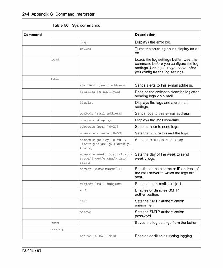
244 Appendix G Command Interpreter
N0115791
disp Displays the error log.
online Turns the error log online display on or off.
load Loads the log settings buffer. Use this command before you configure the log settings. Use sys logs save after you configure the log settings.
alertAddr [mail address] Sends alerts to this e-mail address.
clearLog [0:no/1:yes] Enables the switch to clear the log after sending logs via e-mail.
display Displays the logs and alerts mail settings.
logAddr [mail address] Sends logs to this e-mail address.
schedule display Displays the mail schedule.
schedule hour [0-23] Sets the hour to send logs.
schedule minute [0-59] Sets the minute to send the logs.
schedule policy [0:full/1:hourly/2:daily/3:weekly/4:none]
Sets the mail schedule policy.
schedule week [0:sun/1:mon/2:tue/3:wed/4:thu/5:fri/6:sat]
Sets the day of the week to send weekly logs.
server [domainName/IP] Sets the domain name or IP address of the mail server to which the logs are sent.
subject [mail subject] Sets the log e-mail’s subject.
auth Enables or disables SMTP authentication.
user Sets the SMTP authentication username.
passwd Sets the SMTP authentication password.
save Saves the log settings from the buffer.
syslog
active [0:no/1:yes] Enables or disables syslog logging.
Table 56 Sys commands
Command Description
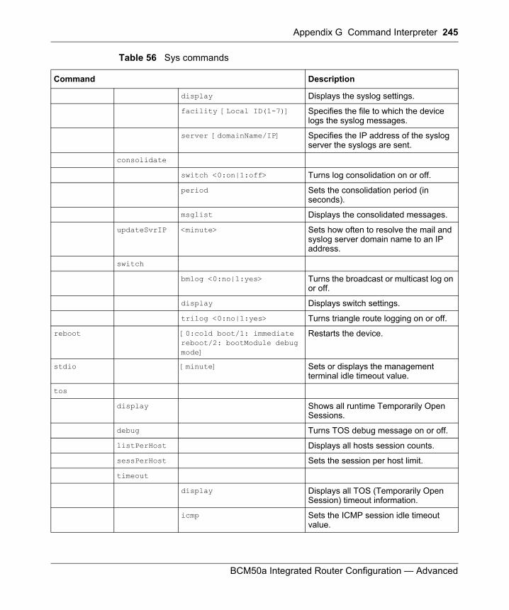
Appendix G Command Interpreter 245
BCM50a Integrated Router Configuration — Advanced
display Displays the syslog settings.
facility [Local ID(1-7)] Specifies the file to which the device logs the syslog messages.
server [domainName/IP] Specifies the IP address of the syslog server the syslogs are sent.
consolidate
switch <0:on|1:off> Turns log consolidation on or off.
period Sets the consolidation period (in seconds).
msglist Displays the consolidated messages.
updateSvrIP <minute> Sets how often to resolve the mail and syslog server domain name to an IP address.
switch
bmlog <0:no|1:yes> Turns the broadcast or multicast log on or off.
display Displays switch settings.
trilog <0:no|1:yes> Turns triangle route logging on or off.
reboot [0:cold boot/1: immediate reboot/2: bootModule debug mode]
Restarts the device.
stdio [minute] Sets or displays the management terminal idle timeout value.
tos
display Shows all runtime Temporarily Open Sessions.
debug Turns TOS debug message on or off.
listPerHost Displays all hosts session counts.
sessPerHost Sets the session per host limit.
timeout
display Displays all TOS (Temporarily Open Session) timeout information.
icmp Sets the ICMP session idle timeout value.
Table 56 Sys commands
Command Description
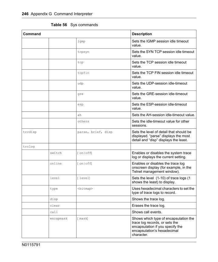
246 Appendix G Command Interpreter
N0115791
igmp Sets the IGMP session idle timeout value.
tcpsyn Sets the SYN TCP session idle timeout value.
tcp Sets the TCP session idle timeout value.
tcpfin Sets the TCP FIN session idle timeout value.
udp Sets the UDP-session idle-timeout value.
gre Sets the GRE-session idle-timeout value.
esp Sets the ESP-session idle-timeout value.
ah Sets the AH-session idle-timeout value.
others Sets the idle-timeout value for other sessions.
trcdisp parse, brief, disp Sets the level of detail that should be displayed. “parse” displays the most detail and “disp” displays the least.
trclog
switch [on|off] Enables or disables the system trace log or displays the current setting.
online [on|off] Enables or disables the trace log onscreen display (for example, in the Telnet management window).
level [level] Sets the level (1-10) of trace logs (1 shows the least) to display.
type <bitmap> Uses hexadecimal characters to set the type of trace logs to record.
disp Shows the trace log.
clear Erases the trace log.
call Shows call events.
encapmask [mask] Shows which type of encapsulation the trace log records, or sets the encapsulation if you specify the encapsulation’s hexadecimal character.
Table 56 Sys commands
Command Description
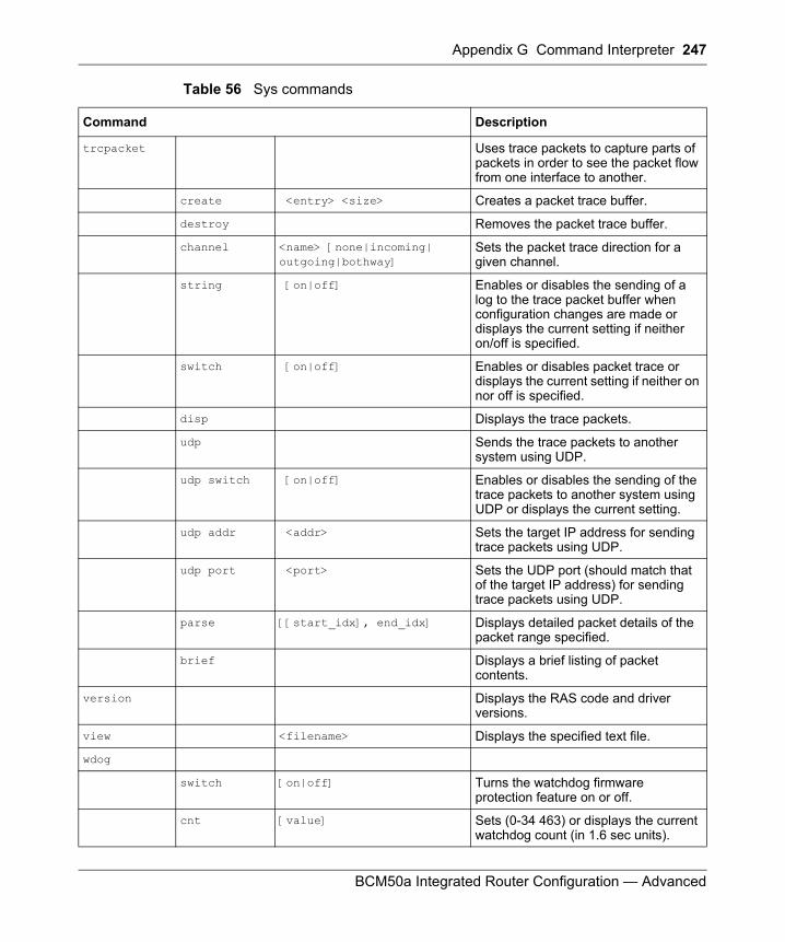
Appendix G Command Interpreter 247
BCM50a Integrated Router Configuration — Advanced
trcpacket Uses trace packets to capture parts of packets in order to see the packet flow from one interface to another.
create <entry> <size> Creates a packet trace buffer.
destroy Removes the packet trace buffer.
channel <name> [none|incoming| outgoing|bothway]
Sets the packet trace direction for a given channel.
string [on|off] Enables or disables the sending of a log to the trace packet buffer when configuration changes are made or displays the current setting if neither on/off is specified.
switch [on|off] Enables or disables packet trace or displays the current setting if neither on nor off is specified.
disp Displays the trace packets.
udp Sends the trace packets to another system using UDP.
udp switch [on|off] Enables or disables the sending of the trace packets to another system using UDP or displays the current setting.
udp addr <addr> Sets the target IP address for sending trace packets using UDP.
udp port <port> Sets the UDP port (should match that of the target IP address) for sending trace packets using UDP.
parse [[start_idx], end_idx] Displays detailed packet details of the packet range specified.
brief Displays a brief listing of packet contents.
version Displays the RAS code and driver versions.
view <filename> Displays the specified text file.
wdog
switch [on|off] Turns the watchdog firmware protection feature on or off.
cnt [value] Sets (0-34 463) or displays the current watchdog count (in 1.6 sec units).
Table 56 Sys commands
Command Description
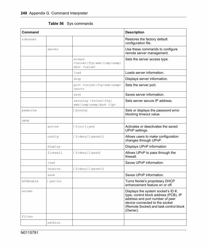
248 Appendix G Command Interpreter
N0115791
romreset Restores the factory default configuration file.
server Use these commands to configure remote server management.
access <telnet|ftp|web|icmp|snmp|dns> <value>
Sets the server access type.
load Loads server information.
disp Displays server information.
port <telnet|ftp|web|snmp> <port>
Sets the server port.
save Saves server information.
secureip <telnet|ftp| web|icmp|snmp|dns> <ip>
Sets server secure IP address.
pwderrtm [minute] Sets or displays the password error blocking timeout value.
upnp
active [0:no/1:yes] Activates or deactivates the saved UPnP settings.
config [0:deny/1:permit] Allows users to make configuration changes through UPnP.
display Displays UPnP information
firewall [0:deny/1:pass] Allows UPnP to pass through the firewall.
load Saves UPnP information.
reserve [0:deny/1:permit]
save Saves UPnP information.
m50Enable [yes|no] Turns Nortel’s proprietary DHCP enhancement feature on or off.
socket Displays the system socket’s ID #, type, control block address (PCB), IP address and port number of peer device connected to the socket (Remote Socket) and task control block (Owner).
filter
netbios
Table 56 Sys commands
Command Description
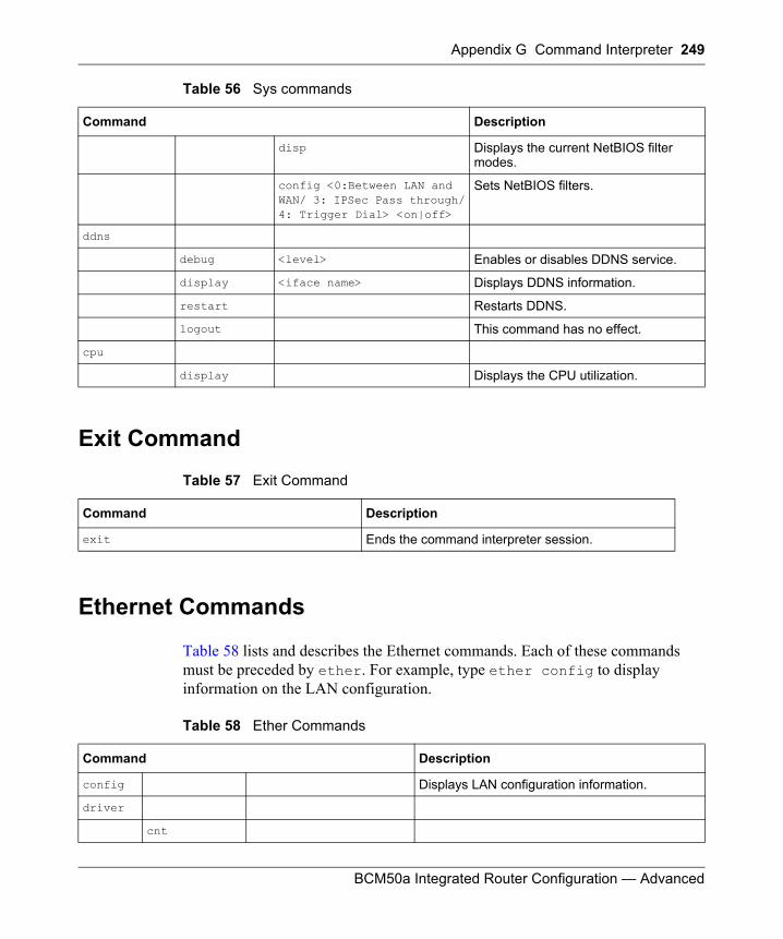
Appendix G Command Interpreter 249
BCM50a Integrated Router Configuration — Advanced
Exit Command
Ethernet Commands
Table 58 lists and describes the Ethernet commands. Each of these commands must be preceded by ether. For example, type ether config to display information on the LAN configuration.
disp Displays the current NetBIOS filter modes.
config <0:Between LAN and WAN/ 3: IPSec Pass through/4: Trigger Dial> <on|off>
Sets NetBIOS filters.
ddns
debug <level> Enables or disables DDNS service.
display <iface name> Displays DDNS information.
restart Restarts DDNS.
logout This command has no effect.
cpu
display Displays the CPU utilization.
Table 57 Exit Command
Command Description
exit Ends the command interpreter session.
Table 58 Ether Commands
Command Description
config Displays LAN configuration information.
driver
cnt
Table 56 Sys commands
Command Description
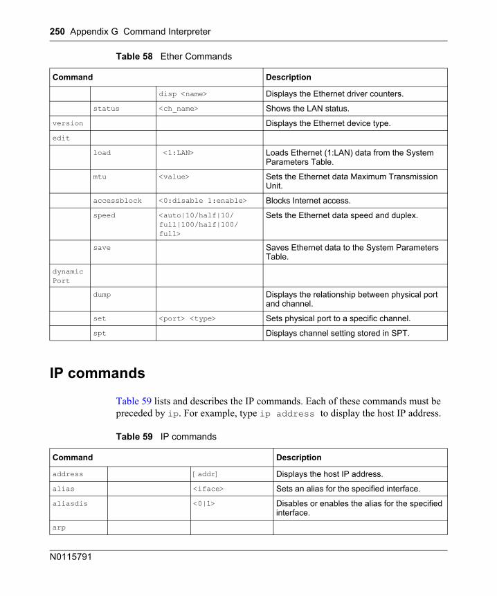
250 Appendix G Command Interpreter
N0115791
IP commands
Table 59 lists and describes the IP commands. Each of these commands must be preceded by ip. For example, type ip address to display the host IP address.
disp <name> Displays the Ethernet driver counters.
status <ch_name> Shows the LAN status.
version Displays the Ethernet device type.
edit
load <1:LAN> Loads Ethernet (1:LAN) data from the System Parameters Table.
mtu <value> Sets the Ethernet data Maximum Transmission Unit.
accessblock <0:disable 1:enable> Blocks Internet access.
speed <auto|10/half|10/full|100/half|100/full>
Sets the Ethernet data speed and duplex.
save Saves Ethernet data to the System Parameters Table.
dynamicPort
dump Displays the relationship between physical port and channel.
set <port> <type> Sets physical port to a specific channel.
spt Displays channel setting stored in SPT.
Table 59 IP commands
Command Description
address [addr] Displays the host IP address.
alias <iface> Sets an alias for the specified interface.
aliasdis <0|1> Disables or enables the alias for the specified interface.
arp
Table 58 Ether Commands
Command Description
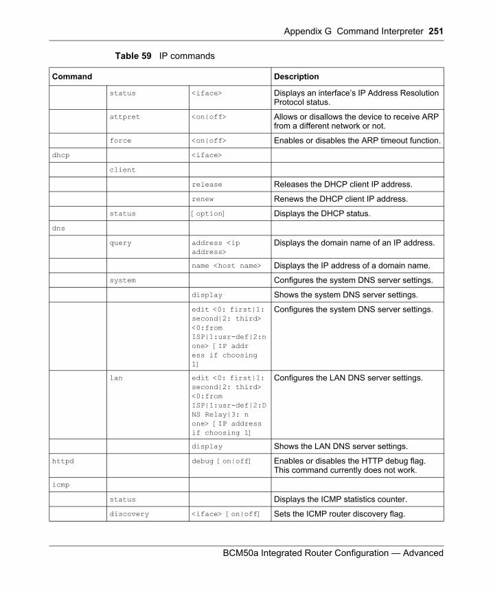
Appendix G Command Interpreter 251
BCM50a Integrated Router Configuration — Advanced
status <iface> Displays an interface’s IP Address Resolution Protocol status.
attpret <on|off> Allows or disallows the device to receive ARP from a different network or not.
force <on|off> Enables or disables the ARP timeout function.
dhcp <iface>
client
release Releases the DHCP client IP address.
renew Renews the DHCP client IP address.
status [option] Displays the DHCP status.
dns
query address <ip address>
Displays the domain name of an IP address.
name <host name> Displays the IP address of a domain name.
system Configures the system DNS server settings.
display Shows the system DNS server settings.
edit <0: first|1: second|2: third> <0:from ISP|1:usr-def|2:none> [IP address if choosing 1]
Configures the system DNS server settings.
lan edit <0: first|1: second|2: third> <0:from ISP|1:usr-def|2:DNS Relay|3: none> [IP address if choosing 1]
Configures the LAN DNS server settings.
display Shows the LAN DNS server settings.
httpd debug [on|off] Enables or disables the HTTP debug flag. This command currently does not work.
icmp
status Displays the ICMP statistics counter.
discovery <iface> [on|off] Sets the ICMP router discovery flag.
Table 59 IP commands
Command Description
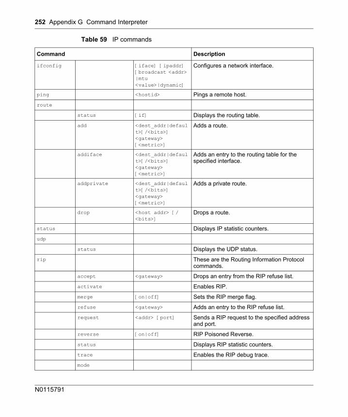
252 Appendix G Command Interpreter
N0115791
ifconfig [iface] [ipaddr] [broadcast <addr> |mtu <value>|dynamic]
Configures a network interface.
ping <hostid> Pings a remote host.
route
status [if] Displays the routing table.
add <dest_addr|default>[/<bits>] <gateway> [<metric>]
Adds a route.
addiface <dest_addr|default>[/<bits>] <gateway> [<metric>]
Adds an entry to the routing table for the specified interface.
addprivate <dest_addr|default>[/<bits>] <gateway> [<metric>]
Adds a private route.
drop <host addr> [/<bits>]
Drops a route.
status Displays IP statistic counters.
udp
status Displays the UDP status.
rip These are the Routing Information Protocol commands.
accept <gateway> Drops an entry from the RIP refuse list.
activate Enables RIP.
merge [on|off] Sets the RIP merge flag.
refuse <gateway> Adds an entry to the RIP refuse list.
request <addr> [port] Sends a RIP request to the specified address and port.
reverse [on|off] RIP Poisoned Reverse.
status Displays RIP statistic counters.
trace Enables the RIP debug trace.
mode
Table 59 IP commands
Command Description
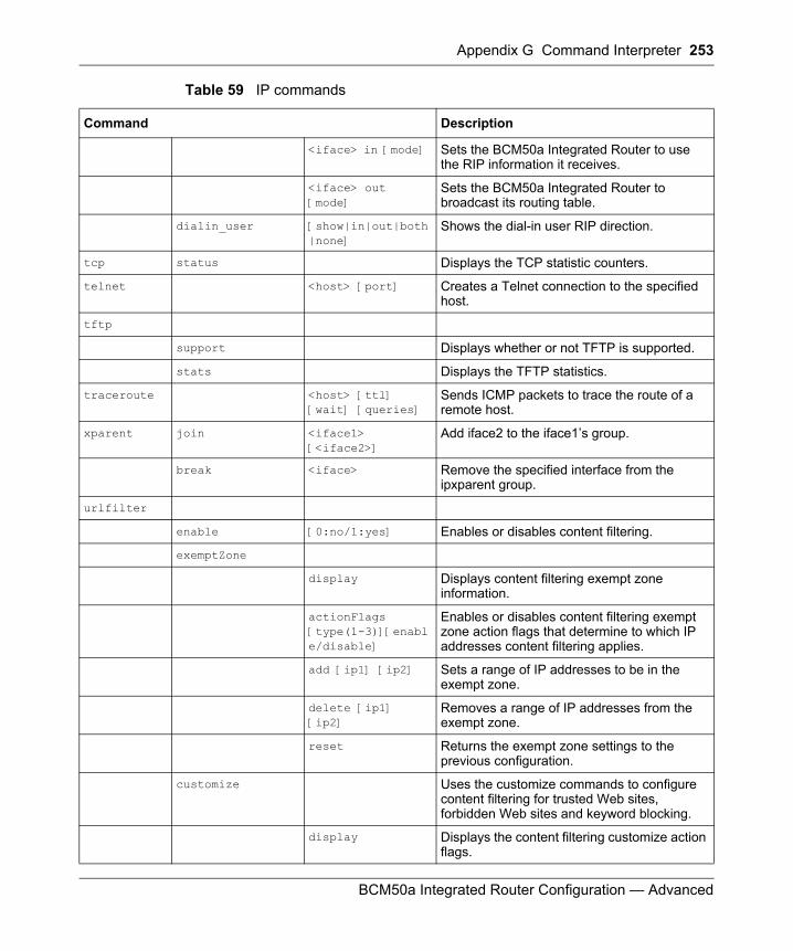
Appendix G Command Interpreter 253
BCM50a Integrated Router Configuration — Advanced
<iface> in [mode] Sets the BCM50a Integrated Router to use the RIP information it receives.
<iface> out [mode]
Sets the BCM50a Integrated Router to broadcast its routing table.
dialin_user [show|in|out|both|none]
Shows the dial-in user RIP direction.
tcp status Displays the TCP statistic counters.
telnet <host> [port] Creates a Telnet connection to the specified host.
tftp
support Displays whether or not TFTP is supported.
stats Displays the TFTP statistics.
traceroute <host> [ttl] [wait] [queries]
Sends ICMP packets to trace the route of a remote host.
xparent join <iface1> [<iface2>]
Add iface2 to the iface1’s group.
break <iface> Remove the specified interface from the ipxparent group.
urlfilter
enable [0:no/1:yes] Enables or disables content filtering.
exemptZone
display Displays content filtering exempt zone information.
actionFlags [type(1-3)][enable/disable]
Enables or disables content filtering exempt zone action flags that determine to which IP addresses content filtering applies.
add [ip1] [ip2] Sets a range of IP addresses to be in the exempt zone.
delete [ip1] [ip2]
Removes a range of IP addresses from the exempt zone.
reset Returns the exempt zone settings to the previous configuration.
customize Uses the customize commands to configure content filtering for trusted Web sites, forbidden Web sites and keyword blocking.
display Displays the content filtering customize action flags.
Table 59 IP commands
Command Description
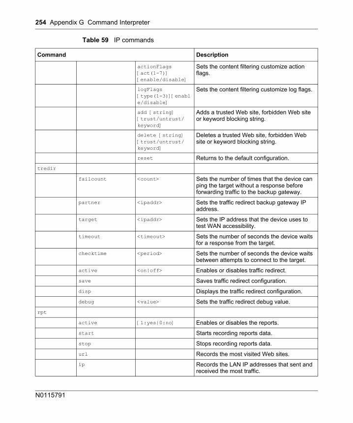
254 Appendix G Command Interpreter
N0115791
actionFlags [act(1-7)] [enable/disable]
Sets the content filtering customize action flags.
logFlags [type(1-3)][enable/disable]
Sets the content filtering customize log flags.
add [string] [trust/untrust/keyword]
Adds a trusted Web site, forbidden Web site or keyword blocking string.
delete [string] [trust/untrust/keyword]
Deletes a trusted Web site, forbidden Web site or keyword blocking string.
reset Returns to the default configuration.
tredir
failcount <count> Sets the number of times that the device can ping the target without a response before forwarding traffic to the backup gateway.
partner <ipaddr> Sets the traffic redirect backup gateway IP address.
target <ipaddr> Sets the IP address that the device uses to test WAN accessibility.
timeout <timeout> Sets the number of seconds the device waits for a response from the target.
checktime <period> Sets the number of seconds the device waits between attempts to connect to the target.
active <on|off> Enables or disables traffic redirect.
save Saves traffic redirect configuration.
disp Displays the traffic redirect configuration.
debug <value> Sets the traffic redirect debug value.
rpt
active [1:yes|0:no] Enables or disables the reports.
start Starts recording reports data.
stop Stops recording reports data.
url Records the most visited Web sites.
ip Records the LAN IP addresses that sent and received the most traffic.
Table 59 IP commands
Command Description
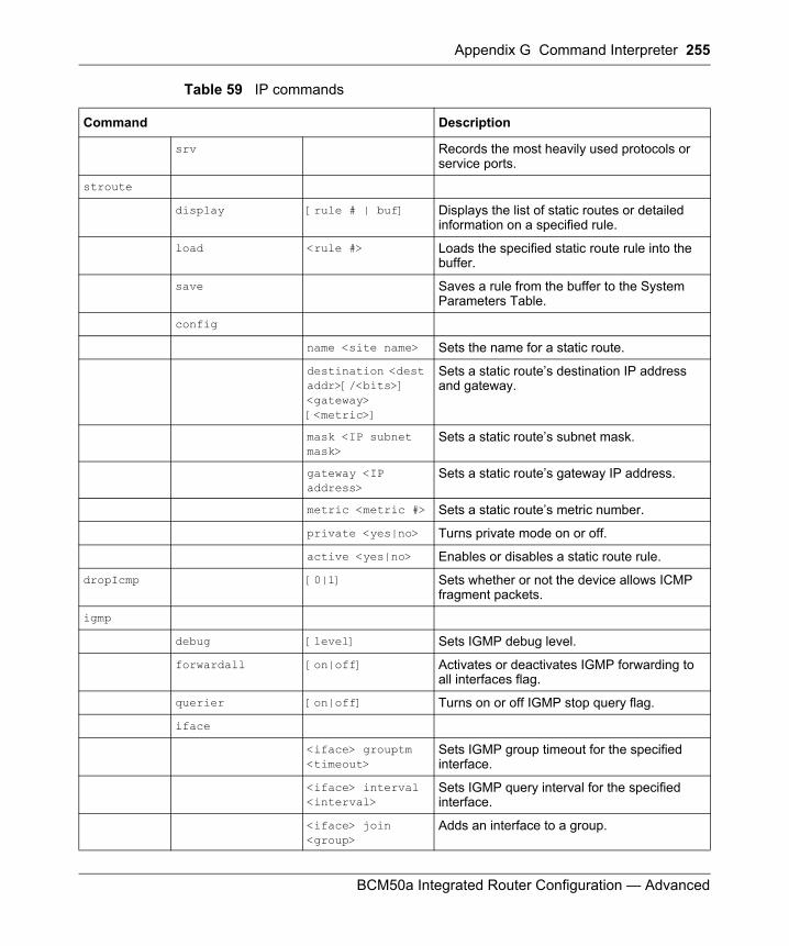
Appendix G Command Interpreter 255
BCM50a Integrated Router Configuration — Advanced
srv Records the most heavily used protocols or service ports.
stroute
display [rule # | buf] Displays the list of static routes or detailed information on a specified rule.
load <rule #> Loads the specified static route rule into the buffer.
save Saves a rule from the buffer to the System Parameters Table.
config
name <site name> Sets the name for a static route.
destination <dest addr>[/<bits>] <gateway> [<metric>]
Sets a static route’s destination IP address and gateway.
mask <IP subnet mask>
Sets a static route’s subnet mask.
gateway <IP address>
Sets a static route’s gateway IP address.
metric <metric #> Sets a static route’s metric number.
private <yes|no> Turns private mode on or off.
active <yes|no> Enables or disables a static route rule.
dropIcmp [0|1] Sets whether or not the device allows ICMP fragment packets.
igmp
debug [level] Sets IGMP debug level.
forwardall [on|off] Activates or deactivates IGMP forwarding to all interfaces flag.
querier [on|off] Turns on or off IGMP stop query flag.
iface
<iface> grouptm <timeout>
Sets IGMP group timeout for the specified interface.
<iface> interval <interval>
Sets IGMP query interval for the specified interface.
<iface> join <group>
Adds an interface to a group.
Table 59 IP commands
Command Description
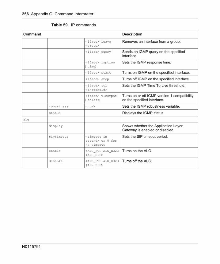
256 Appendix G Command Interpreter
N0115791
<iface> leave <group>
Removes an interface from a group.
<iface> query Sends an IGMP query on the specified interface.
<iface> rsptime [time]
Sets the IGMP response time.
<iface> start Turns on IGMP on the specified interface.
<iface> stop Turns off IGMP on the specified interface.
<iface> ttl <threshold>
Sets the IGMP Time To Live threshold.
<iface> v1compat [on|off]
Turns on or off IGMP version 1 compatibility on the specified interface.
robustness <num> Sets the IGMP robustness variable.
status Displays the IGMP status.
alg
display Shows whether the Application Layer Gateway is enabled or disabled.
siptimeout <timeout in second> or 0 for no timeout
Sets the SIP timeout period.
enable <ALG_FTP|ALG_H323|ALG_SIP>
Turns on the ALG.
disable <ALG_FTP|ALG_H323|ALG_SIP>
Turns off the ALG.
Table 59 IP commands
Command Description
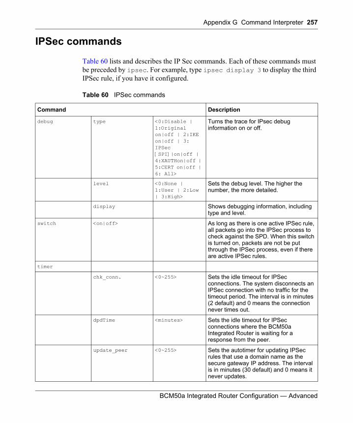
Appendix G Command Interpreter 257
BCM50a Integrated Router Configuration — Advanced
IPSec commands
Table 60 lists and describes the IP Sec commands. Each of these commands must be preceded by ipsec. For example, type ipsec display 3 to display the third IPSec rule, if you have it configured.
Table 60 IPSec commands
Command Description
debug type <0:Disable | 1:Original on|off | 2:IKE on|off | 3: IPSec [SPI]|on|off | 4:XAUTHon|off | 5:CERT on|off | 6: All>
Turns the trace for IPsec debug information on or off.
level <0:None | 1:User | 2:Low | 3:High>
Sets the debug level. The higher the number, the more detailed.
display Shows debugging information, including type and level.
switch <on|off> As long as there is one active IPSec rule, all packets go into the IPSec process to check against the SPD. When this switch is turned on, packets are not be put through the IPSec process, even if there are active IPSec rules.
timer
chk_conn. <0~255> Sets the idle timeout for IPSec connections. The system disconnects an IPSec connection with no traffic for the timeout period. The interval is in minutes (2 default) and 0 means the connection never times out.
dpdTime <minutes> Sets the idle timeout for IPSec connections where the BCM50a Integrated Router is waiting for a response from the peer.
update_peer <0~255> Sets the autotimer for updating IPSec rules that use a domain name as the secure gateway IP address. The interval is in minutes (30 default) and 0 means it never updates.
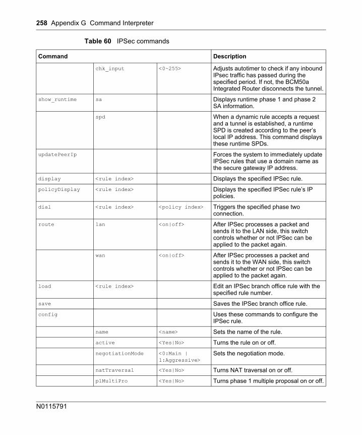
258 Appendix G Command Interpreter
N0115791
chk_input <0~255> Adjusts autotimer to check if any inbound IPsec traffic has passed during the specified period. If not, the BCM50a Integrated Router disconnects the tunnel.
show_runtime sa Displays runtime phase 1 and phase 2 SA information.
spd When a dynamic rule accepts a request and a tunnel is established, a runtime SPD is created according to the peer’s local IP address. This command displays these runtime SPDs.
updatePeerIp Forces the system to immediately update IPSec rules that use a domain name as the secure gateway IP address.
display <rule index> Displays the specified IPSec rule.
policyDisplay <rule index> Displays the specified IPSec rule’s IP policies.
dial <rule index> <policy index> Triggers the specified phase two connection.
route lan <on|off> After IPSec processes a packet and sends it to the LAN side, this switch controls whether or not IPSec can be applied to the packet again.
wan <on|off> After IPSec processes a packet and sends it to the WAN side, this switch controls whether or not IPSec can be applied to the packet again.
load <rule index> Edit an IPSec branch office rule with the specified rule number.
save Saves the IPSec branch office rule.
config Uses these commands to configure the IPSec rule.
name <name> Sets the name of the rule.
active <Yes|No> Turns the rule on or off.
negotiationMode <0:Main | 1:Aggressive>
Sets the negotiation mode.
natTraversal <Yes|No> Turns NAT traversal on or off.
p1MultiPro <Yes|No> Turns phase 1 multiple proposal on or off.
Table 60 IPSec commands
Command Description
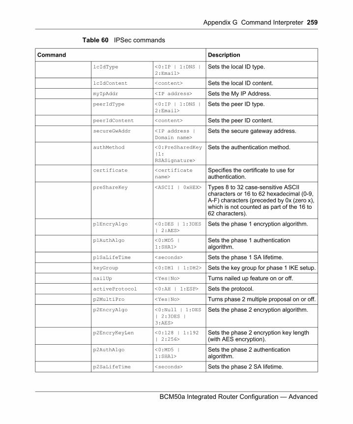
Appendix G Command Interpreter 259
BCM50a Integrated Router Configuration — Advanced
lcIdType <0:IP | 1:DNS | 2:Email>
Sets the local ID type.
lcIdContent <content> Sets the local ID content.
myIpAddr <IP address> Sets the My IP Address.
peerIdType <0:IP | 1:DNS | 2:Email>
Sets the peer ID type.
peerIdContent <content> Sets the peer ID content.
secureGwAddr <IP address | Domain name>
Sets the secure gateway address.
authMethod <0:PreSharedKey |1: RSASignature>
Sets the authentication method.
certificate <certificate name>
Specifies the certificate to use for authentication.
preShareKey <ASCII | 0xHEX> Types 8 to 32 case-sensitive ASCII characters or 16 to 62 hexadecimal (0-9, A-F) characters (preceded by 0x (zero x), which is not counted as part of the 16 to 62 characters).
p1EncryAlgo <0:DES | 1:3DES | 2:AES>
Sets the phase 1 encryption algorithm.
p1AuthAlgo <0:MD5 | 1:SHA1>
Sets the phase 1 authentication algorithm.
p1SaLifeTime <seconds> Sets the phase 1 SA lifetime.
keyGroup <0:DH1 | 1:DH2> Sets the key group for phase 1 IKE setup.
nailUp <Yes|No> Turns nailed up feature on or off.
activeProtocol <0:AH | 1:ESP> Sets the protocol.
p2MultiPro <Yes|No> Turns phase 2 multiple proposal on or off.
p2EncryAlgo <0:Null | 1:DES | 2:3DES | 3:AES>
Sets the phase 2 encryption algorithm.
p2EncryKeyLen <0:128 | 1:192 | 2:256>
Sets the phase 2 encryption key length (with AES encryption).
p2AuthAlgo <0:MD5 | 1:SHA1>
Sets the phase 2 authentication algorithm.
p2SaLifeTime <seconds> Sets the phase 2 SA lifetime.
Table 60 IPSec commands
Command Description
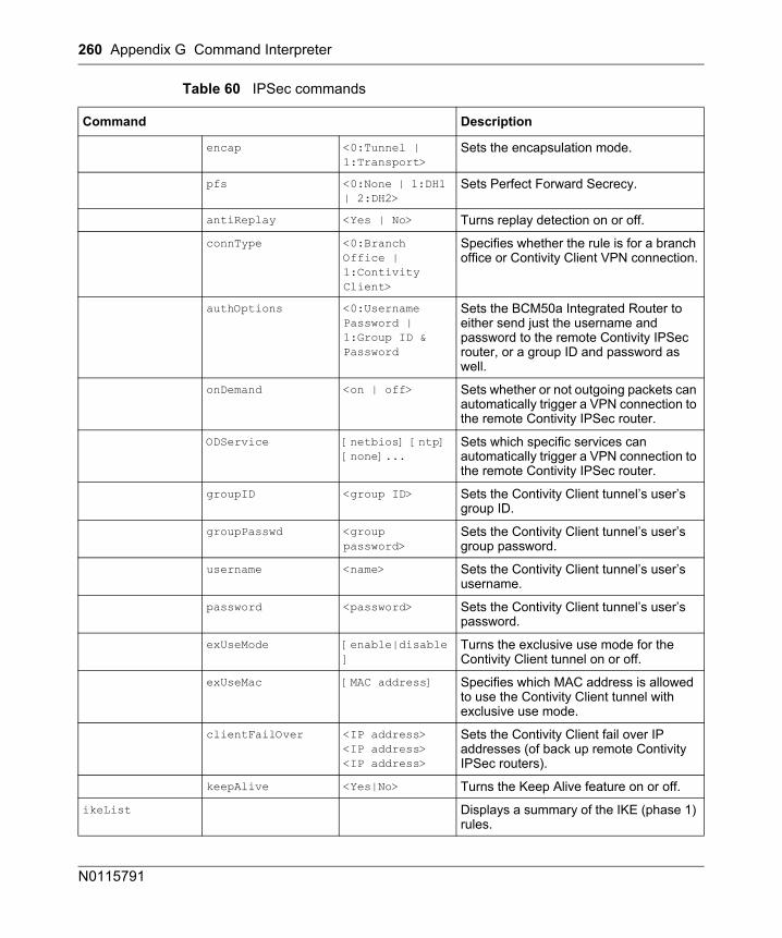
260 Appendix G Command Interpreter
N0115791
encap <0:Tunnel | 1:Transport>
Sets the encapsulation mode.
pfs <0:None | 1:DH1 | 2:DH2>
Sets Perfect Forward Secrecy.
antiReplay <Yes | No> Turns replay detection on or off.
connType <0:Branch Office | 1:Contivity Client>
Specifies whether the rule is for a branch office or Contivity Client VPN connection.
authOptions <0:Username Password | 1:Group ID & Password
Sets the BCM50a Integrated Router to either send just the username and password to the remote Contivity IPSec router, or a group ID and password as well.
onDemand <on | off> Sets whether or not outgoing packets can automatically trigger a VPN connection to the remote Contivity IPSec router.
ODService [netbios] [ntp] [none]...
Sets which specific services can automatically trigger a VPN connection to the remote Contivity IPSec router.
groupID <group ID> Sets the Contivity Client tunnel’s user’s group ID.
groupPasswd <group password>
Sets the Contivity Client tunnel’s user’s group password.
username <name> Sets the Contivity Client tunnel’s user’s username.
password <password> Sets the Contivity Client tunnel’s user’s password.
exUseMode [enable|disable]
Turns the exclusive use mode for the Contivity Client tunnel on or off.
exUseMac [MAC address] Specifies which MAC address is allowed to use the Contivity Client tunnel with exclusive use mode.
clientFailOver <IP address> <IP address> <IP address>
Sets the Contivity Client fail over IP addresses (of back up remote Contivity IPSec routers).
keepAlive <Yes|No> Turns the Keep Alive feature on or off.
ikeList Displays a summary of the IKE (phase 1) rules.
Table 60 IPSec commands
Command Description
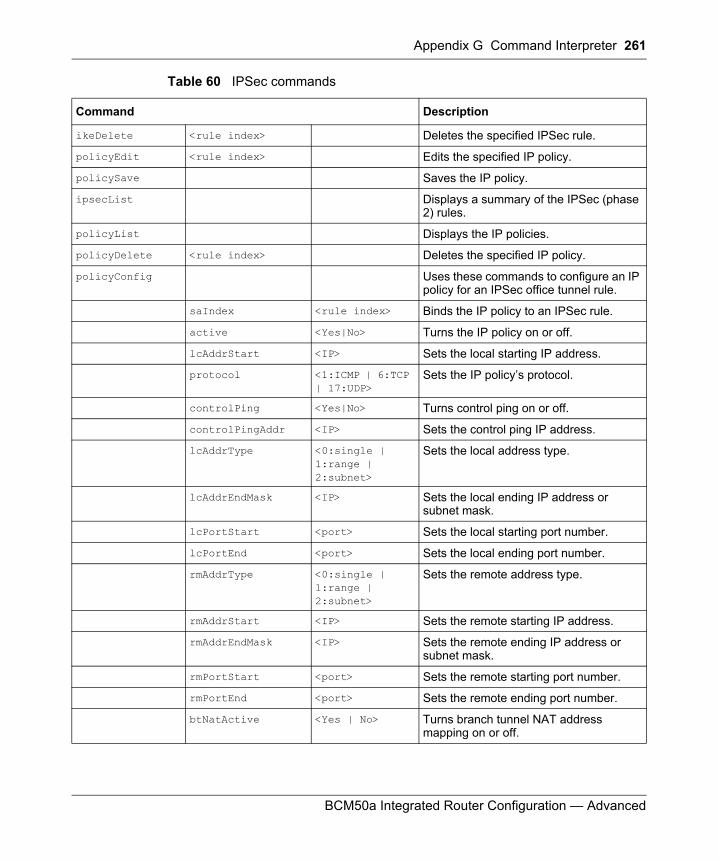
Appendix G Command Interpreter 261
BCM50a Integrated Router Configuration — Advanced
ikeDelete <rule index> Deletes the specified IPSec rule.
policyEdit <rule index> Edits the specified IP policy.
policySave Saves the IP policy.
ipsecList Displays a summary of the IPSec (phase 2) rules.
policyList Displays the IP policies.
policyDelete <rule index> Deletes the specified IP policy.
policyConfig Uses these commands to configure an IP policy for an IPSec office tunnel rule.
saIndex <rule index> Binds the IP policy to an IPSec rule.
active <Yes|No> Turns the IP policy on or off.
lcAddrStart <IP> Sets the local starting IP address.
protocol <1:ICMP | 6:TCP | 17:UDP>
Sets the IP policy’s protocol.
controlPing <Yes|No> Turns control ping on or off.
controlPingAddr <IP> Sets the control ping IP address.
lcAddrType <0:single | 1:range | 2:subnet>
Sets the local address type.
lcAddrEndMask <IP> Sets the local ending IP address or subnet mask.
lcPortStart <port> Sets the local starting port number.
lcPortEnd <port> Sets the local ending port number.
rmAddrType <0:single | 1:range | 2:subnet>
Sets the remote address type.
rmAddrStart <IP> Sets the remote starting IP address.
rmAddrEndMask <IP> Sets the remote ending IP address or subnet mask.
rmPortStart <port> Sets the remote starting port number.
rmPortEnd <port> Sets the remote ending port number.
btNatActive <Yes | No> Turns branch tunnel NAT address mapping on or off.
Table 60 IPSec commands
Command Description
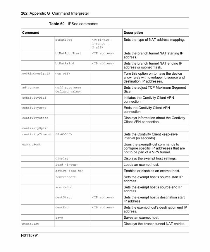
262 Appendix G Command Interpreter
N0115791
btNatType <0:single | 1:range | 2:all>
Sets the type of NAT address mapping.
btNatAddrStart <IP address> Sets the branch tunnel NAT starting IP address.
btNatArEnd <IP address> Sets the branch tunnel NAT ending IP address or subnet mask.
swSkipOverlapIP <on|off> Turn this option on to have the device allow rules with overlapping source and destination IP addresses.
adjTcpMss <off|auto|user defined value>
Sets the adjust TCP Maximum Segment Size.
contivityDial Initiates the Contivity Client VPN connection.
contivityDrop Ends the Contivity Client VPN connection.
contivityState Displays information about the Contivity Client VPN connection.
contivitySplit
contivityTimecnt <0~65535> Sets the Contivity Client keep-alive interval (in seconds).
exemptHost Uses the exemptHost commands to configure specific IP addresses that are not to be part of a VPN tunnel.
display Displays the exempt host settings.
load <index> Loads an exempt host.
active <Yes|No> Enables or disables an exempt host.
sourceStart Sets the exempt host’s source start IP address.
sourceEnd Sets the exempt host’s source end IP address.
destStart <IP address> Sets the exempt host’s destination start IP address.
destEnd <IP address> Sets the exempt host’s destination end IP address.
save Saves an exempt host.
btNatList Displays the branch tunnel NAT entries.
Table 60 IPSec commands
Command Description
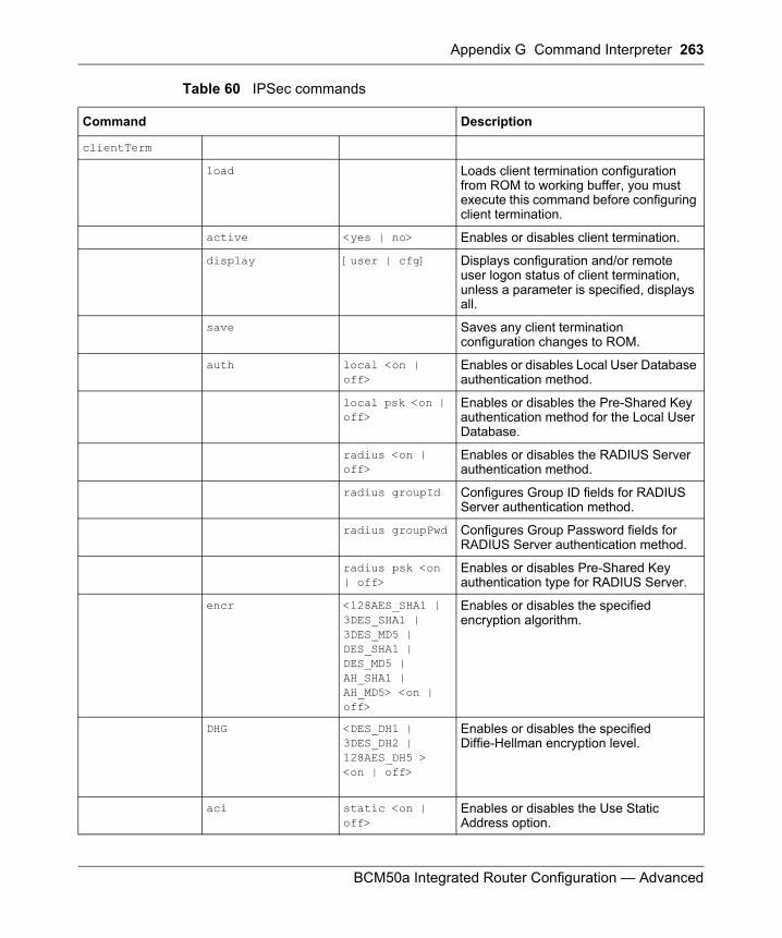
Appendix G Command Interpreter 263
BCM50a Integrated Router Configuration — Advanced
clientTerm
load Loads client termination configuration from ROM to working buffer, you must execute this command before configuring client termination.
active <yes | no> Enables or disables client termination.
display [user | cfg] Displays configuration and/or remote user logon status of client termination, unless a parameter is specified, displays all.
save Saves any client termination configuration changes to ROM.
auth local <on | off>
Enables or disables Local User Database authentication method.
local psk <on | off>
Enables or disables the Pre-Shared Key authentication method for the Local User Database.
radius <on | off>
Enables or disables the RADIUS Server authentication method.
radius groupId Configures Group ID fields for RADIUS Server authentication method.
radius groupPwd Configures Group Password fields for RADIUS Server authentication method.
radius psk <on | off>
Enables or disables Pre-Shared Key authentication type for RADIUS Server.
encr <128AES_SHA1 | 3DES_SHA1 | 3DES_MD5 | DES_SHA1 | DES_MD5 | AH_SHA1 | AH_MD5> <on | off>
Enables or disables the specified encryption algorithm.
DHG <DES_DH1 | 3DES_DH2 | 128AES_DH5 > <on | off>
Enables or disables the specified Diffie-Hellman encryption level.
aci static <on | off>
Enables or disables the Use Static Address option.
Table 60 IPSec commands
Command Description
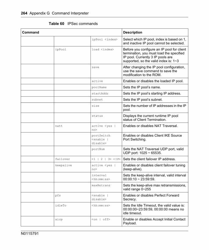
264 Appendix G Command Interpreter
N0115791
ipPool <index> Select which IP pool, index is based on 1, and inactive IP pool cannot be selected.
ipPool load <index> Before you configure an IP pool for client termination, you must load the specified IP pool. Currently 3 IP pools are supported, so the valid index is: 1~3
save After changing the IP pool configuration, use the save command to save the modification to the ROM.
active Enables or disables the loaded IP pool.
poolName Sets the IP pool’s name.
startAddr Sets the IP pool’s starting IP address.
subnet Sets the IP pool’s subnet.
size Sets the number of IP addresses in the IP pool.
status Displays the current runtime IP pool status of Client Termination.
natt active <yes | no>
Enables or disables NAT Traversal.
portSwitch <enable | disable>
Enables or disables Client IKE Source Port Switching.
portNum Sets the NAT Traversal UDP port, valid UDP port: 1025 ~ 65535.
failover <1 | 2 | 3> <IP> Sets the client failover IP address.
keepalive active <yes | no>
Enables or disables client failover tuning (keep-alive).
interval <hh:mm:ss>
Sets the keep-alive interval, valid interval 00:00:10 ~ 23:59:59.
maxRetrans Sets the keep-alive max retransmissions, valid range 0~255
pfs <enable | disable>
Enables or disables Perfect Forward Secrecy.
idleTo <hh:mm:ss> Sets the Idle Timeout, the valid value is: 00:00:00~23:59:59, 00:00:00 means no idle timeout.
aicp <on | off> Enable or disables Accept Initial Contact Payload.
Table 60 IPSec commands
Command Description
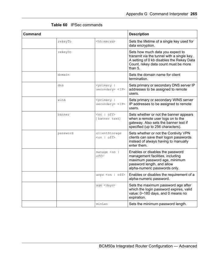
Appendix G Command Interpreter 265
BCM50a Integrated Router Configuration — Advanced
rekeyTo <hh:mm:ss> Sets the lifetime of a single key used for data encryption.
rekeyDc Sets how much data you expect to transmit via the tunnel with a single key. A setting of 0 kb disables the Rekey Data Count, rekey data count must be more than 5.
domain Sets the domain name for client termination.
dns <primary | secondary> <IP>
Sets primary or secondary DNS server IP addresses to be assigned to remote users.
wins <primary | secondary> <IP>
Sets primary or secondary WINS server IP addresses to be assigned to remote users.
banner <on | off> [banner text]
Sets whether or not the banner appears when a remote user logs on to the gateway. Also sets the banner text if specified (up to 256 characters).
password clientStorage <on | off>
Sets whether or not the Contivity VPN clients can save their logon passwords instead of always having to manually enter them.
manage <on | off>
Enables or disables the password management facilities, including maximum password age, minimum password length, and allow alpha-numeric passwords only.
anpr <on | off> Enables or disables the requirement of a alpha-numeric password.
age <days> Sets the maximum password age after which the login password expires, valid value: 0~180 days, and 0 means no expiration.
minLen Sets the minimum password length.
Table 60 IPSec commands
Command Description
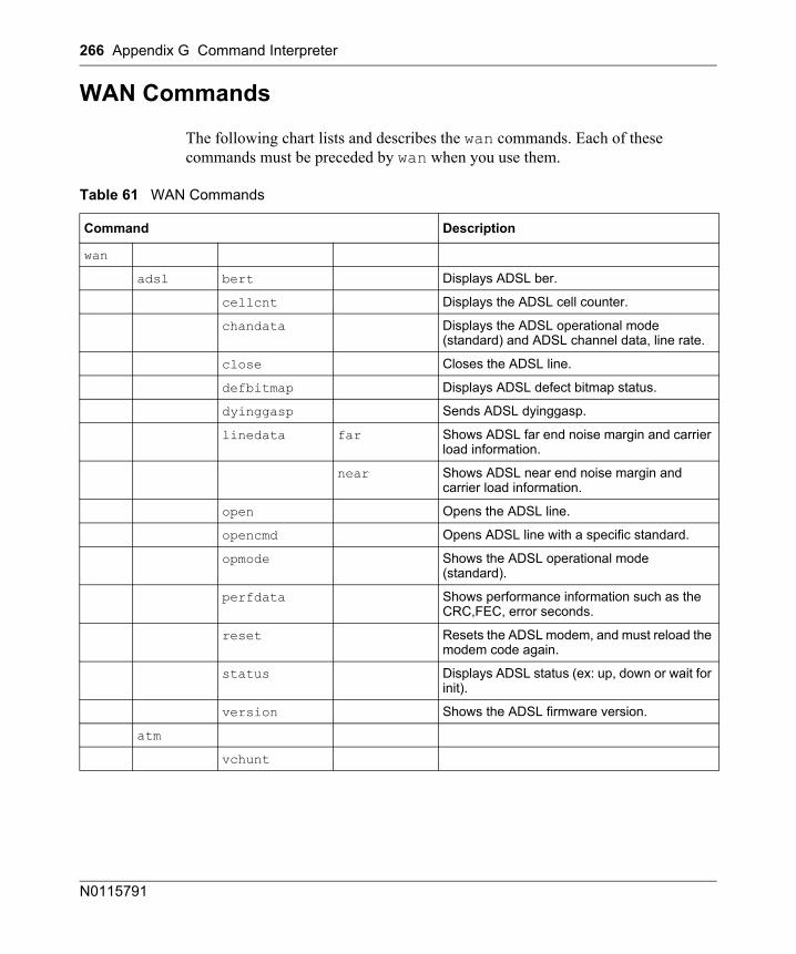
266 Appendix G Command Interpreter
N0115791
WAN Commands
The following chart lists and describes the wan commands. Each of these commands must be preceded by wan when you use them.
Table 61 WAN Commands
Command Description
wan
adsl bert Displays ADSL ber.
cellcnt Displays the ADSL cell counter.
chandata Displays the ADSL operational mode (standard) and ADSL channel data, line rate.
close Closes the ADSL line.
defbitmap Displays ADSL defect bitmap status.
dyinggasp Sends ADSL dyinggasp.
linedata far Shows ADSL far end noise margin and carrier load information.
near Shows ADSL near end noise margin and carrier load information.
open Opens the ADSL line.
opencmd Opens ADSL line with a specific standard.
opmode Shows the ADSL operational mode (standard).
perfdata Shows performance information such as the CRC,FEC, error seconds.
reset Resets the ADSL modem, and must reload the modem code again.
status Displays ADSL status (ex: up, down or wait for init).
version Shows the ADSL firmware version.
atm
vchunt
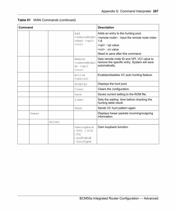
Appendix G Command Interpreter 267
BCM50a Integrated Router Configuration — Advanced
Add <remoteNodeIndex> <vpi> <vci>
Adds an entry to the hunting pool. <remote node> : input the remote node index 1-8<vpi> : vpi value <vci> : vci valueNeed to save after this command.
Remove <removeNodeId> <vpi> <vci>
Sets remote node ID and VPI, VCI value to remove the specific entry. System will save automatically.
Active <yes|no>
Enables/disables VC auto hunting feature.
display Displays the hunt pool.
Clear Clears the configuration.
Save Saves current setting to the ROM file.
timer Sets the waiting time before checking the hunting table result.
Send Sends VC hunt pattern again.
hwsar Displays hwsar packets incoming/outgoing information.
driver
Oamloopback [VPI] [VCI] [F5] [endToEnd] [funcType]
Oam loopback function.
Table 61 WAN Commands (continued)
Command Description
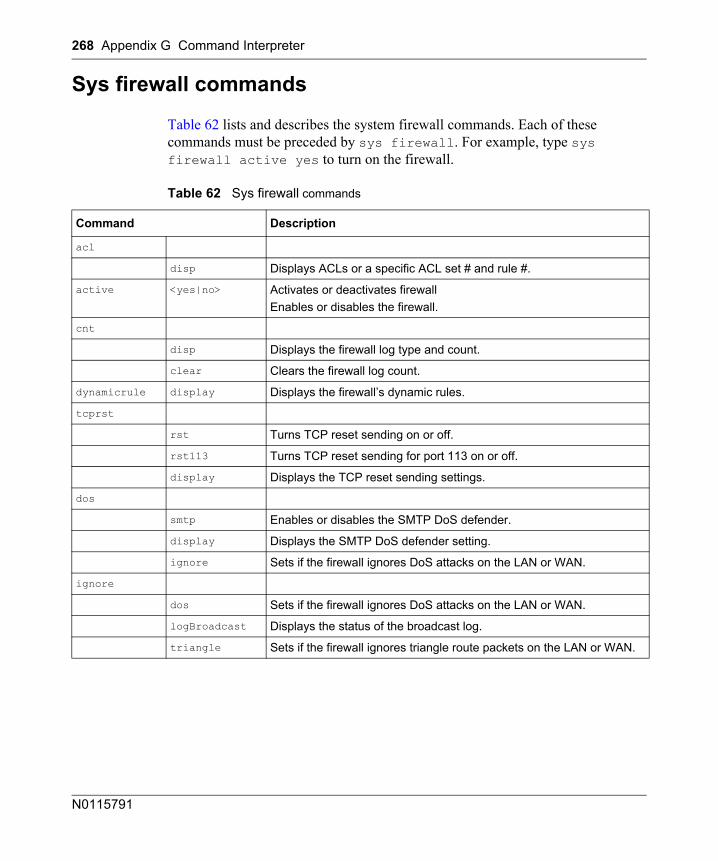
268 Appendix G Command Interpreter
N0115791
Sys firewall commands
Table 62 lists and describes the system firewall commands. Each of these commands must be preceded by sys firewall. For example, type sys firewall active yes to turn on the firewall.
Table 62 Sys firewall commands
Command Description
acl
disp Displays ACLs or a specific ACL set # and rule #.
active <yes|no> Activates or deactivates firewallEnables or disables the firewall.
cnt
disp Displays the firewall log type and count.
clear Clears the firewall log count.
dynamicrule display Displays the firewall’s dynamic rules.
tcprst
rst Turns TCP reset sending on or off.
rst113 Turns TCP reset sending for port 113 on or off.
display Displays the TCP reset sending settings.
dos
smtp Enables or disables the SMTP DoS defender.
display Displays the SMTP DoS defender setting.
ignore Sets if the firewall ignores DoS attacks on the LAN or WAN.
ignore
dos Sets if the firewall ignores DoS attacks on the LAN or WAN.
logBroadcast Displays the status of the broadcast log.
triangle Sets if the firewall ignores triangle route packets on the LAN or WAN.
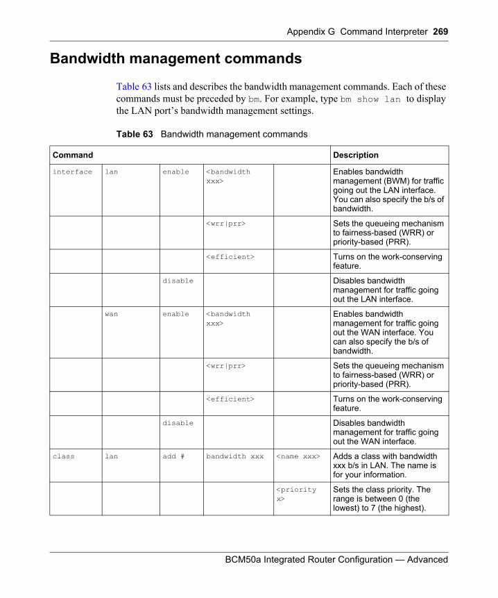
Appendix G Command Interpreter 269
BCM50a Integrated Router Configuration — Advanced
Bandwidth management commands
Table 63 lists and describes the bandwidth management commands. Each of these commands must be preceded by bm. For example, type bm show lan to display the LAN port’s bandwidth management settings.
Table 63 Bandwidth management commands
Command Description
interface lan enable <bandwidth xxx>
Enables bandwidth management (BWM) for traffic going out the LAN interface. You can also specify the b/s of bandwidth.
<wrr|prr> Sets the queueing mechanism to fairness-based (WRR) or priority-based (PRR).
<efficient> Turns on the work-conserving feature.
disable Disables bandwidth management for traffic going out the LAN interface.
wan enable <bandwidth xxx>
Enables bandwidth management for traffic going out the WAN interface. You can also specify the b/s of bandwidth.
<wrr|prr> Sets the queueing mechanism to fairness-based (WRR) or priority-based (PRR).
<efficient> Turns on the work-conserving feature.
disable Disables bandwidth management for traffic going out the WAN interface.
class lan add # bandwidth xxx <name xxx> Adds a class with bandwidth xxx b/s in LAN. The name is for your information.
<priority x>
Sets the class priority. The range is between 0 (the lowest) to 7 (the highest).
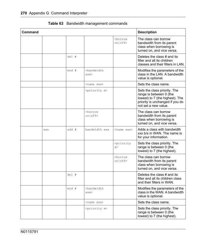
270 Appendix G Command Interpreter
N0115791
<borrow on|off>
The class can borrow bandwidth from its parent class when borrowing is turned on, and vice versa.
del # Deletes the class # and its filter and all its children classes and their filters in LAN.
mod # <bandwidth xxx>
Modifies the parameters of the class in the LAN. A bandwidth value is optional.
<name xxx> Sets the class name.
<priority x> Sets the class priority. The range is between 0 (the lowest) to 7 (the highest). The priority is unchanged if you do not set a new value.
<borrow on|off>
The class can borrow bandwidth from its parent class when borrowing is turned on, and vice versa.
wan add # bandwidth xxx <name xxx> Adds a class with bandwidth xxx b/s in WAN. The name is for your information.
<priority x>
Sets the class priority. The range is between 0 (the lowest) to 7 (the highest).
<borrow on|off>
The class can borrow bandwidth from its parent class when borrowing is turned on, and vice versa.
del # Deletes the class # and its filter and all its children class and their filters in WAN.
mod # <bandwidth xxx>
Modifies the parameters of the class in the WAN. A bandwidth value is optional.
<name xxx> Sets the class name.
<priority x> Sets the class priority. The range is between 0 (the lowest) to 7 (the highest).
Table 63 Bandwidth management commands
Command Description
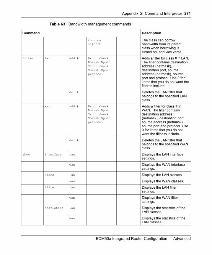
Appendix G Command Interpreter 271
BCM50a Integrated Router Configuration — Advanced
<borrow on|off>
The class can borrow bandwidth from its parent class when borrowing is turned on, and vice versa.
filter lan add # Daddr <mask Dmask> Dport Saddr <mask Smask> Sport protocol
Adds a filter for class # in LAN. The filter contains destination address (netmask), destination port, source address (netmask), source port and protocol. Use 0 for items that you do not want the filter to include.
del # Deletes the LAN filter that belongs to the specified LAN class.
wan add # Daddr <mask Dmask> Dport Saddr <mask Smask> Sport protocol
Adds a filter for class # in WAN. The filter contains destination address (netmask), destination port, source address (netmask), source port and protocol. Use 0 for items that you do not want the filter to include.
del # Deletes the LAN filter that belongs to the specified WAN class.
show interface lan Displays the LAN interface settings.
wan Displays the WAN interface settings.
class lan Displays the LAN classes.
wan Displays the WAN classes.
filter lan Displays the LAN filter settings.
wan Displays the WAN filter settings.
statistics lan Displays the statistics of the LAN classes.
wan Displays the statistics of the LAN classes.
Table 63 Bandwidth management commands
Command Description
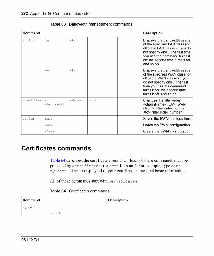
272 Appendix G Command Interpreter
N0115791
Certificates commands
Table 64 describes the certificate commands. Each of these commands must be preceded by certificates (or cert for short). For example, type cert my_cert list to display all of your certificate names and basic information.
All of these commands start with certificates.
monitor lan <#> Displays the bandwidth usage of the specified LAN class (or all of the LAN classes if you do not specify one). The first time you use the command turns it on; the second time turns it off, and so on.
wan <#> Displays the bandwidth usage of the specified WAN class (or all of the WAN classes if you do not specify one). The first time you use the command turns it on; the second time turns it off, and so on.
moveFilter < channName>
<from> <to> Changes the filter order. <channName>: LAN, WAN <from>: filter index number <to>: filter index number
config save Saves the BWM configuration.
load Loads the BWM configuration.
clear Clears the BWM configuration.
Table 64 Certificates commands
Command Description
my_cert
create
Table 63 Bandwidth management commands
Command Description
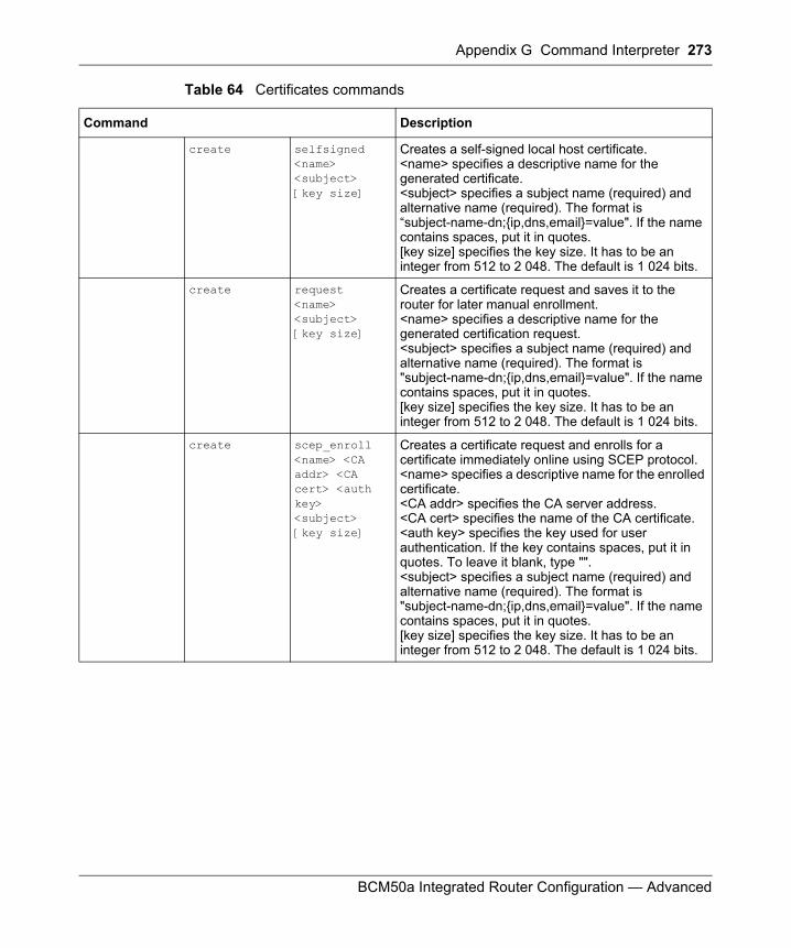
Appendix G Command Interpreter 273
BCM50a Integrated Router Configuration — Advanced
create selfsigned <name> <subject> [key size]
Creates a self-signed local host certificate. <name> specifies a descriptive name for the generated certificate. <subject> specifies a subject name (required) and alternative name (required). The format is “subject-name-dn;{ip,dns,email}=value". If the name contains spaces, put it in quotes. [key size] specifies the key size. It has to be an integer from 512 to 2 048. The default is 1 024 bits.
create request <name> <subject> [key size]
Creates a certificate request and saves it to the router for later manual enrollment. <name> specifies a descriptive name for the generated certification request. <subject> specifies a subject name (required) and alternative name (required). The format is "subject-name-dn;{ip,dns,email}=value". If the name contains spaces, put it in quotes. [key size] specifies the key size. It has to be an integer from 512 to 2 048. The default is 1 024 bits.
create scep_enroll <name> <CA addr> <CA cert> <auth key> <subject> [key size]
Creates a certificate request and enrolls for a certificate immediately online using SCEP protocol. <name> specifies a descriptive name for the enrolled certificate. <CA addr> specifies the CA server address. <CA cert> specifies the name of the CA certificate. <auth key> specifies the key used for user authentication. If the key contains spaces, put it in quotes. To leave it blank, type "". <subject> specifies a subject name (required) and alternative name (required). The format is "subject-name-dn;{ip,dns,email}=value". If the name contains spaces, put it in quotes. [key size] specifies the key size. It has to be an integer from 512 to 2 048. The default is 1 024 bits.
Table 64 Certificates commands
Command Description
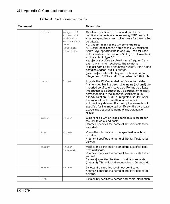
274 Appendix G Command Interpreter
N0115791
create cmp_enroll <name> <CA addr> <CA cert> <auth key> <subject> [key size]
Creates a certificate request and enrolls for a certificate immediately online using CMP protocol. <name> specifies a descriptive name for the enrolled certificate. <CA addr> specifies the CA server address. <CA cert> specifies the name of the CA certificate. <auth key> specifies the id and key used for user authentication. The format is "id:key". To leave the id and key blank, type ":". <subject> specifies a subject name (required) and alternative name (required). The format is "subject-name-dn;{ip,dns,email}=value". If the name contains spaces, put it in quotes. [key size] specifies the key size. It has to be an integer from 512 to 2 048. The default is 1 024 bits.
import [name] Imports the PEM-encoded certificate from stdin. [name] specifies the descriptive name (optional) the imported certificate is saved as. For my certificate importation to be successful, a certification request corresponding to the imported certificate must already exist on BCM50a Integrated Router. After the importation, the certification request is automatically deleted. If a descriptive name is not specified for the imported certificate, the certificate adopts the descriptive name of the certification request.
export <name> Exports the PEM-encoded certificate to stdout for theuser to copy and paste. <name> specifies the name of the certificate to be exported.
view <name> Views the information of the specified local host certificate. <name> specifies the name of the certificate to be viewed.
verify <name> [timeout]
Verifies the certification path of the specified local host certificate. <name> specifies the name of the certificate to be verified.[timeout] specifies the timeout value in seconds (optional). The default timeout value is 20 seconds.
delete <name> Deletes the specified local host certificate.<name> specifies the name of the certificate to be deleted.
list Lists all my certificate names and basic information.
Table 64 Certificates commands
Command Description
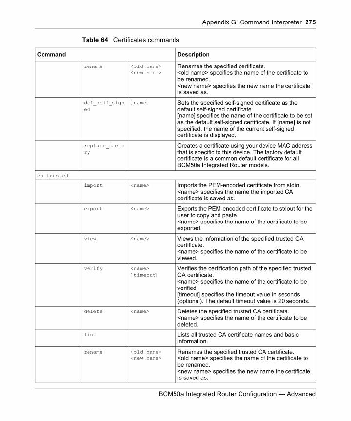
Appendix G Command Interpreter 275
BCM50a Integrated Router Configuration — Advanced
rename <old name> <new name>
Renames the specified certificate. <old name> specifies the name of the certificate to be renamed. <new name> specifies the new name the certificate is saved as.
def_self_signed
[name] Sets the specified self-signed certificate as the default self-signed certificate. [name] specifies the name of the certificate to be set as the default self-signed certificate. If [name] is not specified, the name of the current self-signed certificate is displayed.
replace_factory
Creates a certificate using your device MAC address that is specific to this device. The factory default certificate is a common default certificate for all BCM50a Integrated Router models.
ca_trusted
import <name> Imports the PEM-encoded certificate from stdin. <name> specifies the name the imported CA certificate is saved as.
export <name> Exports the PEM-encoded certificate to stdout for the user to copy and paste.<name> specifies the name of the certificate to be exported.
view <name> Views the information of the specified trusted CA certificate. <name> specifies the name of the certificate to be viewed.
verify <name> [timeout]
Verifies the certification path of the specified trusted CA certificate. <name> specifies the name of the certificate to be verified. [timeout] specifies the timeout value in seconds (optional). The default timeout value is 20 seconds.
delete <name> Deletes the specified trusted CA certificate. <name> specifies the name of the certificate to be deleted.
list Lists all trusted CA certificate names and basic information.
rename <old name> <new name>
Renames the specified trusted CA certificate. <old name> specifies the name of the certificate to be renamed. <new name> specifies the new name the certificate is saved as.
Table 64 Certificates commands
Command Description
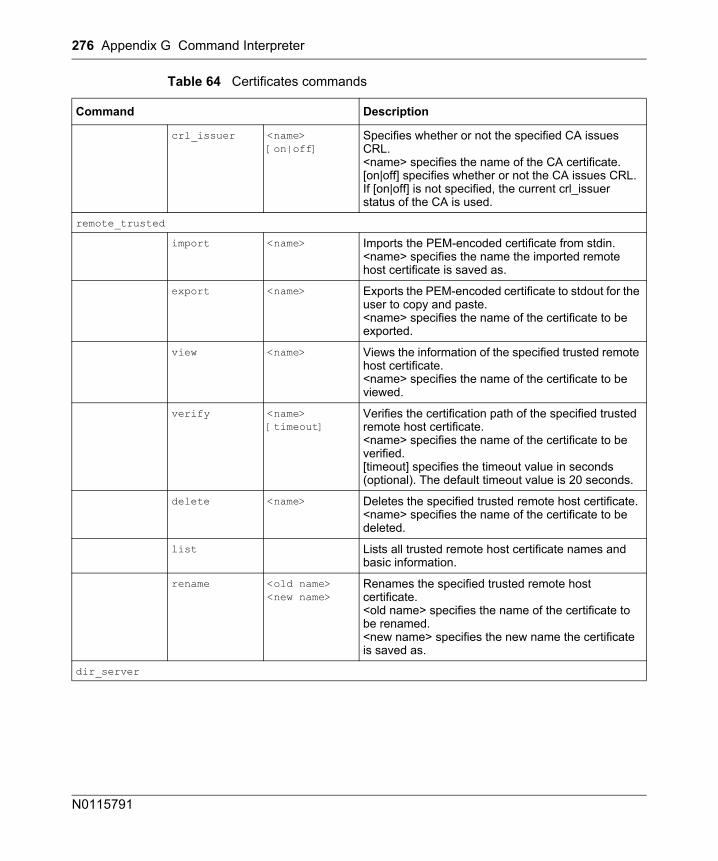
276 Appendix G Command Interpreter
N0115791
crl_issuer <name> [on|off]
Specifies whether or not the specified CA issues CRL. <name> specifies the name of the CA certificate. [on|off] specifies whether or not the CA issues CRL. If [on|off] is not specified, the current crl_issuer status of the CA is used.
remote_trusted
import <name> Imports the PEM-encoded certificate from stdin. <name> specifies the name the imported remote host certificate is saved as.
export <name> Exports the PEM-encoded certificate to stdout for the user to copy and paste. <name> specifies the name of the certificate to be exported.
view <name> Views the information of the specified trusted remote host certificate. <name> specifies the name of the certificate to be viewed.
verify <name> [timeout]
Verifies the certification path of the specified trusted remote host certificate. <name> specifies the name of the certificate to be verified. [timeout] specifies the timeout value in seconds (optional). The default timeout value is 20 seconds.
delete <name> Deletes the specified trusted remote host certificate. <name> specifies the name of the certificate to be deleted.
list Lists all trusted remote host certificate names and basic information.
rename <old name> <new name>
Renames the specified trusted remote host certificate. <old name> specifies the name of the certificate to be renamed. <new name> specifies the new name the certificate is saved as.
dir_server
Table 64 Certificates commands
Command Description
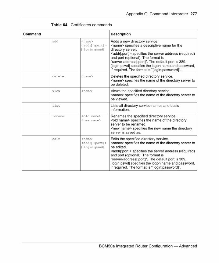
Appendix G Command Interpreter 277
BCM50a Integrated Router Configuration — Advanced
add <name> <addr[:port]> [login:pswd]
Adds a new directory service. <name> specifies a descriptive name for the directory server. <addr[:port]> specifies the server address (required) and port (optional). The format is "server-address[:port]". The default port is 389. [login:pswd] specifies the logon name and password, if required. The format is "[login:password]".
delete <name> Deletes the specified directory service. <name> specifies the name of the directory server to be deleted.
view <name> Views the specified directory service. <name> specifies the name of the directory server to be viewed.
list Lists all directory service names and basic information.
rename <old name> <new name>
Renames the specified directory service. <old name> specifies the name of the directory server to be renamed. <new name> specifies the new name the directory server is saved as.
edit <name> <addr[:port]> [login:pswd]
Edits the specified directory service. <name> specifies the name of the directory server to be edited. <addr[:port]> specifies the server address (required) and port (optional). The format is "server-address[:port]". The default port is 389. [login:pswd] specifies the logon name and password, if required. The format is "[login:password]".
Table 64 Certificates commands
Command Description

278 Appendix G Command Interpreter
N0115791
279
BCM50a Integrated Router Configuration — Advanced
Appendix HNetBIOS filter commands
The following describes the NetBIOS packet filter commands.
Introduction
NetBIOS (Network Basic Input/Output System) are TCP or UDP packets that enable a computer to connect to and communicate with a LAN.
For some dial-up services, such as PPPoE or PPPoA, NetBIOS packets cause unwanted calls.
You can configure NetBIOS filters to do the following:
• Allow or disallow the sending of NetBIOS packets from the LAN to the WAN and from the WAN to the LAN.
• Allow or disallow the sending of NetBIOS packets through VPN connections.• Allow or disallow NetBIOS packets to initiate calls.
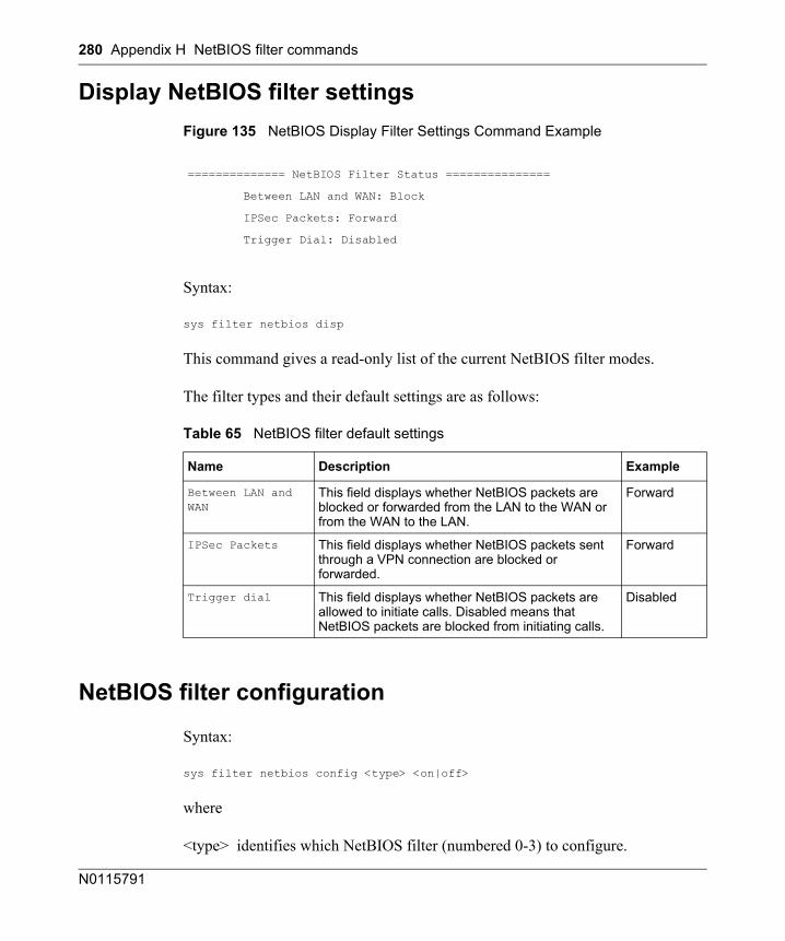
280 Appendix H NetBIOS filter commands
N0115791
Display NetBIOS filter settingsFigure 135 NetBIOS Display Filter Settings Command Example
Syntax:
sys filter netbios disp
This command gives a read-only list of the current NetBIOS filter modes.
The filter types and their default settings are as follows:
NetBIOS filter configuration
Syntax:
sys filter netbios config <type> <on|off>
where
<type> identifies which NetBIOS filter (numbered 0-3) to configure.
============== NetBIOS Filter Status ===============
Between LAN and WAN: Block
IPSec Packets: Forward
Trigger Dial: Disabled
Table 65 NetBIOS filter default settings
Name Description Example
Between LAN and WAN
This field displays whether NetBIOS packets are blocked or forwarded from the LAN to the WAN or from the WAN to the LAN.
Forward
IPSec Packets This field displays whether NetBIOS packets sent through a VPN connection are blocked or forwarded.
Forward
Trigger dial This field displays whether NetBIOS packets are allowed to initiate calls. Disabled means that NetBIOS packets are blocked from initiating calls.
Disabled
Appendix H NetBIOS filter commands 281
BCM50a Integrated Router Configuration — Advanced
• 0 = LAN to WAN and WAN to LAN• 3 = IPSec packet pass through
<on|off> is a switch to enable or disable the filter.
• For type 0, use on to enable the filter and block NetBIOS packets. Use off to disable the filter and forward NetBIOS packets.
• For type 3, use on to block NetBIOS packets from being sent through a VPN connection. Use off to allow NetBIOS packets to be sent through a VPN connection.
Example commands
Command:
sys filter netbios config 0 on
This command blocks LAN to WAN and WAN to LAN NetBIOS packets
Command:
sys filter netbios config 1 off
This command forwards WAN to LAN and WAN to LAN NetBIOS packets
Command:
sys filter netbios config 3 on
This command blocks IPSec NetBIOS packets
Command:
sys filter netbios config 4 off
This command stops NetBIOS commands from initiating calls.
282
BCM50a Integrated Router Configuration — Advanced
Appendix IEnhanced DHCP option commands
The following describes the DHCP option commands.
Enhanced DHCP option commands introduction The enhanced DHCP feature allows you to use DHCP option commands to add site-specific options to the DHCP server’s offer messages.
Specifying the Nortel BCM50 IP address
Syntax:ip dhcp <interface> server m50ipreserve [ [ip <IP address>] | [index <index of pool>] ]
where:
Use this command to specify the IP address that the BCM50a Integrated Router is to assign to the BCM50.
<interface> Specify an interface on the device. Currently you can use this command with the LAN interface (enif0).
[ip <IP address>] This is the IP address that you want to assign to the Nortel BCM50.
[index <index of pool>]
This is the number of an IP address in the BCM50a Integrated Router’s DHCP server address pool (like one or five) that you want to assign to the Nortel BCM50.
For example, you would type “2” to assign the second IP address of the DHCP server pool to the Nortel BCM50.
Appendix I Enhanced DHCP option commands 283
BCM50a Integrated Router Configuration — Advanced
The following example sets the BCM50a Integrated Router to assign an IP address of 11.12.13.10 to the Nortel BCM50.
ip dhcp <interface> server m50ipreserve ip 11.12.13.10
Nortel BCM50 DHCP server optionsUse these commands to add site-specific options to the DHCP server’s offer messages that it sends to the BCM50.
BCM50 DHCP server settings
Syntax:
ip dhcp <interface> server m50dhcpmode [0:disable | 1:IP phones only | 2:All devices | 3:automatic] [<range start>-<range end>]
where:
<interface> Specify an interface on the device. Currently you can use this command with the LAN interface (enif0).
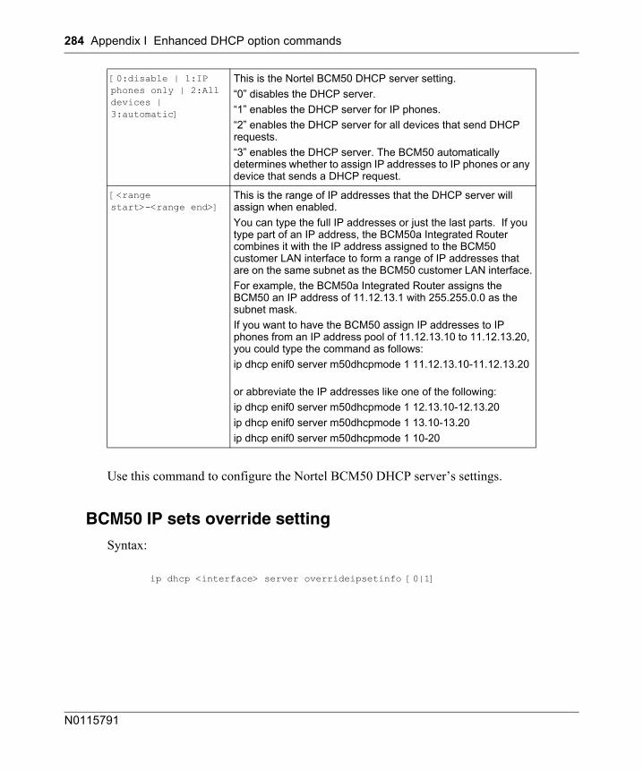
284 Appendix I Enhanced DHCP option commands
N0115791
Use this command to configure the Nortel BCM50 DHCP server’s settings.
BCM50 IP sets override setting
Syntax:
ip dhcp <interface> server overrideipsetinfo [0|1]
[0:disable | 1:IP phones only | 2:All devices | 3:automatic]
This is the Nortel BCM50 DHCP server setting.“0” disables the DHCP server.“1” enables the DHCP server for IP phones.“2” enables the DHCP server for all devices that send DHCP requests.“3” enables the DHCP server. The BCM50 automatically determines whether to assign IP addresses to IP phones or any device that sends a DHCP request.
[<range start>-<range end>]
This is the range of IP addresses that the DHCP server will assign when enabled.You can type the full IP addresses or just the last parts. If you type part of an IP address, the BCM50a Integrated Router combines it with the IP address assigned to the BCM50 customer LAN interface to form a range of IP addresses that are on the same subnet as the BCM50 customer LAN interface.For example, the BCM50a Integrated Router assigns the BCM50 an IP address of 11.12.13.1 with 255.255.0.0 as the subnet mask.If you want to have the BCM50 assign IP addresses to IP phones from an IP address pool of 11.12.13.10 to 11.12.13.20, you could type the command as follows:ip dhcp enif0 server m50dhcpmode 1 11.12.13.10-11.12.13.20
or abbreviate the IP addresses like one of the following:ip dhcp enif0 server m50dhcpmode 1 12.13.10-12.13.20ip dhcp enif0 server m50dhcpmode 1 13.10-13.20ip dhcp enif0 server m50dhcpmode 1 10-20
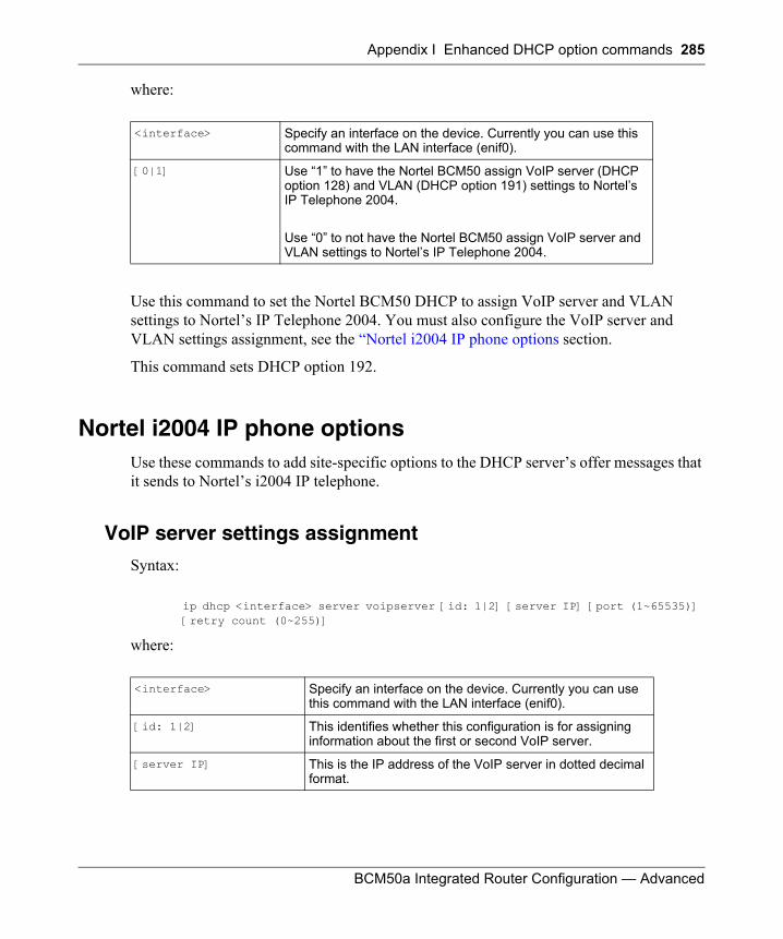
Appendix I Enhanced DHCP option commands 285
BCM50a Integrated Router Configuration — Advanced
where:
Use this command to set the Nortel BCM50 DHCP to assign VoIP server and VLAN settings to Nortel’s IP Telephone 2004. You must also configure the VoIP server and VLAN settings assignment, see the “Nortel i2004 IP phone options section.
This command sets DHCP option 192.
Nortel i2004 IP phone optionsUse these commands to add site-specific options to the DHCP server’s offer messages that it sends to Nortel’s i2004 IP telephone.
VoIP server settings assignment
Syntax:
ip dhcp <interface> server voipserver [id: 1|2] [server IP] [port (1~65535)] [retry count (0~255)]
where:
<interface> Specify an interface on the device. Currently you can use this command with the LAN interface (enif0).
[0|1] Use “1” to have the Nortel BCM50 assign VoIP server (DHCP option 128) and VLAN (DHCP option 191) settings to Nortel’s IP Telephone 2004.
Use “0” to not have the Nortel BCM50 assign VoIP server and VLAN settings to Nortel’s IP Telephone 2004.
<interface> Specify an interface on the device. Currently you can use this command with the LAN interface (enif0).
[id: 1|2] This identifies whether this configuration is for assigning information about the first or second VoIP server.
[server IP] This is the IP address of the VoIP server in dotted decimal format.
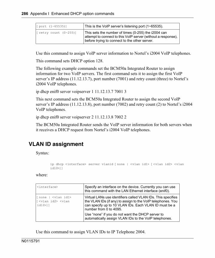
286 Appendix I Enhanced DHCP option commands
N0115791
Use this command to assign VoIP server information to Nortel’s i2004 VoIP telephones.
This command sets DHCP option 128.
The following example commands set the BCM50a Integrated Router to assign information for two VoIP servers. The first command sets it to assign the first VoIP server’s IP address (11.12.13.7), port number (7001) and retry count (three) to Nortel’s i2004 VoIP telephones.
ip dhcp enif0 server voipserver 1 11.12.13.7 7001 3
This next command sets the BCM50a Integrated Router to assign the second VoIP server’s IP address (11.12.13.8), port number (7002) and retry count (2) to Nortel’s i2004 VoIP telephones.
ip dhcp enif0 server voipserver 2 11.12.13.8 7002 2
The BCM50a Integrated Router sends the VoIP server information for both servers when it receives a DHCP request from Nortel’s i2004 VoIP telephones.
VLAN ID assignment
Syntax:
ip dhcp <interface> server vlanid [none | <vlan id1> [<vlan id2> <vlan id10>]]
where:
Use this command to assign VLAN IDs to IP Telephone 2004.
[port (1~65535)] This is the VoIP server’s listening port (1~65535).
[retry count (0~255)] This sets the number of times (0-255) the i2004 can attempt to connect to this VoIP server (without a response), before trying to connect to the other server.
<interface> Specify an interface on the device. Currently you can use this command with the LAN Ethernet interface (enif0).
[none | <vlan id1> [<vlan id2> <vlan id10>]]
Virtual LANs use identifiers called VLAN IDs. This specifies the VLAN IDs (if any) to assign to the VoIP telephones. You can specify up to 10 VLAN IDs. Each VLAN ID must be a number from 0 to 4095. Use “none” if you do not want the DHCP server to automatically assign VLAN IDs to the VoIP telephones.
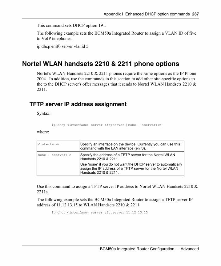
Appendix I Enhanced DHCP option commands 287
BCM50a Integrated Router Configuration — Advanced
This command sets DHCP option 191.
The following example sets the BCM50a Integrated Router to assign a VLAN ID of five to VoIP telephones.
ip dhcp enif0 server vlanid 5
Nortel WLAN handsets 2210 & 2211 phone optionsNortel's WLAN Handsets 2210 & 2211 phones require the same options as the IP Phone 2004. In addition, use the commands in this section to add other site-specific options to the to the DHCP server's offer messages that it sends to Nortel WLAN Handsets 2210 & 2211.
TFTP server IP address assignment
Syntax:
ip dhcp <interface> server tftpserver [none | <serverIP>]
where:
Use this command to assign a TFTP server IP address to Nortel WLAN Handsets 2210 & 2211s.
The following example sets the BCM50a Integrated Router to assign a TFTP server IP address of 11.12.13.15 to WLAN Handsets 2210 & 2211.
ip dhcp <interface> server tftpserver 11.12.13.15
<interface> Specify an interface on the device. Currently you can use this command with the LAN interface (enif0).
none | <serverIP> Specify the address of a TFTP server for the Nortel WLAN Handsets 2210 & 2211. Use “none” if you do not want the DHCP server to automatically assign the IP address of a TFTP server for the Nortel WLAN Handsets 2210 & 2211.
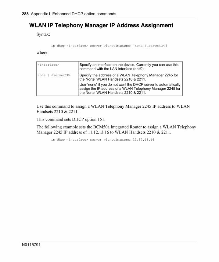
288 Appendix I Enhanced DHCP option commands
N0115791
WLAN IP Telephony Manager IP Address Assignment
Syntax:
ip dhcp <interface> server wlantelmanager [none |<serverIP>]
where:
Use this command to assign a WLAN Telephony Manager 2245 IP address to WLAN Handsets 2210 & 2211.
This command sets DHCP option 151.
The following example sets the BCM50a Integrated Router to assign a WLAN Telephony Manager 2245 IP address of 11.12.13.16 to WLAN Handsets 2210 & 2211.
ip dhcp <interface> server wlantelmanager 11.12.13.16
<interface> Specify an interface on the device. Currently you can use this command with the LAN interface (enif0).
none | <serverIP> Specify the address of a WLAN Telephony Manager 2245 for the Nortel WLAN Handsets 2210 & 2211. Use “none” if you do not want the DHCP server to automatically assign the IP address of a WLAN Telephony Manager 2245 for the Nortel WLAN Handsets 2210 & 2211.
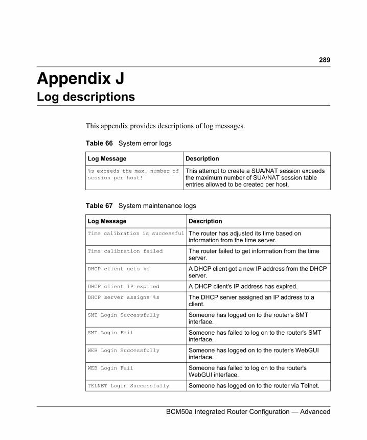
289
BCM50a Integrated Router Configuration — Advanced
Appendix JLog descriptions
This appendix provides descriptions of log messages.
Table 66 System error logs
Log Message Description
%s exceeds the max. number of session per host!
This attempt to create a SUA/NAT session exceeds the maximum number of SUA/NAT session table entries allowed to be created per host.
Table 67 System maintenance logs
Log Message Description
Time calibration is successful The router has adjusted its time based on information from the time server.
Time calibration failed The router failed to get information from the time server.
DHCP client gets %s A DHCP client got a new IP address from the DHCP server.
DHCP client IP expired A DHCP client's IP address has expired.
DHCP server assigns %s The DHCP server assigned an IP address to a client.
SMT Login Successfully Someone has logged on to the router's SMT interface.
SMT Login Fail Someone has failed to log on to the router's SMT interface.
WEB Login Successfully Someone has logged on to the router's WebGUI interface.
WEB Login Fail Someone has failed to log on to the router's WebGUI interface.
TELNET Login Successfully Someone has logged on to the router via Telnet.
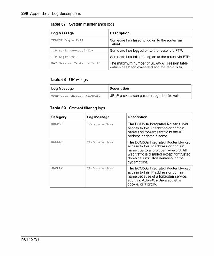
290 Appendix J Log descriptions
N0115791
TELNET Login Fail Someone has failed to log on to the router via Telnet.
FTP Login Successfully Someone has logged on to the router via FTP.
FTP Login Fail Someone has failed to log on to the router via FTP.
NAT Session Table is Full! The maximum number of SUA/NAT session table entries has been exceeded and the table is full.
Table 68 UPnP logs
Log Message Description
UPnP pass through Firewall UPnP packets can pass through the firewall.
Table 69 Content filtering logs
Category Log Message Description
URLFOR IP/Domain Name The BCM50a Integrated Router allows access to this IP address or domain name and forwards traffic to the IP address or domain name.
URLBLK IP/Domain Name The BCM50a Integrated Router blocked access to this IP address or domain name due to a forbidden keyword. All web traffic is disabled except for trusted domains, untrusted domains, or the cybernot list.
JAVBLK IP/Domain Name The BCM50a Integrated Router blocked access to this IP address or domain name because of a forbidden service, such as: ActiveX, a Java applet, a cookie, or a proxy.
Table 67 System maintenance logs
Log Message Description
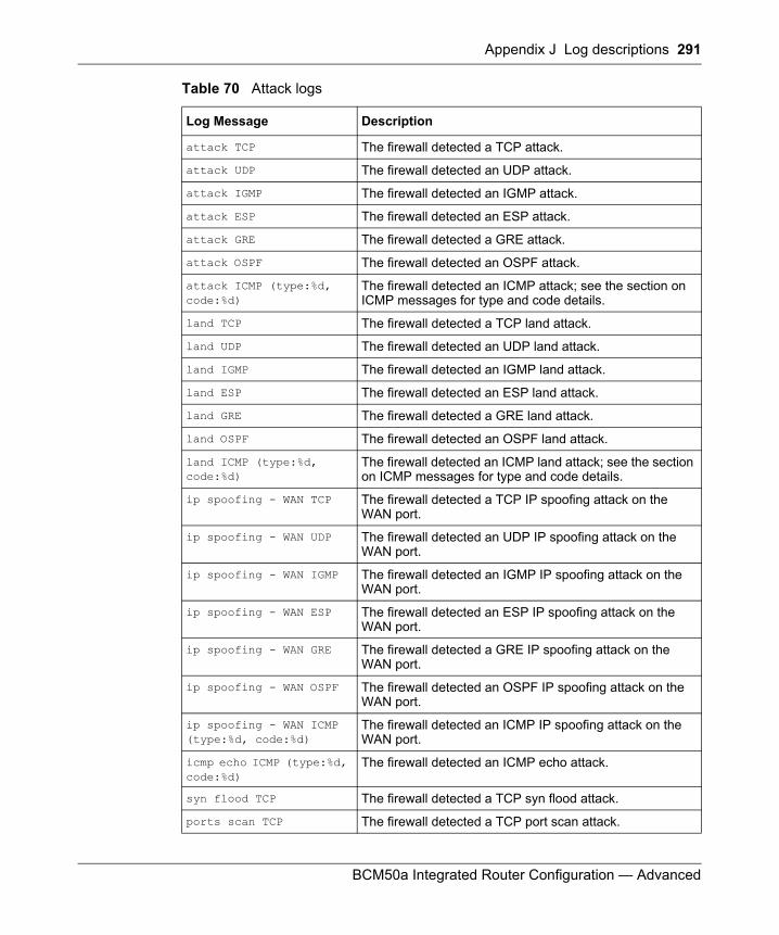
Appendix J Log descriptions 291
BCM50a Integrated Router Configuration — Advanced
Table 70 Attack logs
Log Message Description
attack TCP The firewall detected a TCP attack.
attack UDP The firewall detected an UDP attack.
attack IGMP The firewall detected an IGMP attack.
attack ESP The firewall detected an ESP attack.
attack GRE The firewall detected a GRE attack.
attack OSPF The firewall detected an OSPF attack.
attack ICMP (type:%d, code:%d)
The firewall detected an ICMP attack; see the section on ICMP messages for type and code details.
land TCP The firewall detected a TCP land attack.
land UDP The firewall detected an UDP land attack.
land IGMP The firewall detected an IGMP land attack.
land ESP The firewall detected an ESP land attack.
land GRE The firewall detected a GRE land attack.
land OSPF The firewall detected an OSPF land attack.
land ICMP (type:%d, code:%d)
The firewall detected an ICMP land attack; see the section on ICMP messages for type and code details.
ip spoofing - WAN TCP The firewall detected a TCP IP spoofing attack on the WAN port.
ip spoofing - WAN UDP The firewall detected an UDP IP spoofing attack on the WAN port.
ip spoofing - WAN IGMP The firewall detected an IGMP IP spoofing attack on the WAN port.
ip spoofing - WAN ESP The firewall detected an ESP IP spoofing attack on the WAN port.
ip spoofing - WAN GRE The firewall detected a GRE IP spoofing attack on the WAN port.
ip spoofing - WAN OSPF The firewall detected an OSPF IP spoofing attack on the WAN port.
ip spoofing - WAN ICMP (type:%d, code:%d)
The firewall detected an ICMP IP spoofing attack on the WAN port.
icmp echo ICMP (type:%d, code:%d)
The firewall detected an ICMP echo attack.
syn flood TCP The firewall detected a TCP syn flood attack.
ports scan TCP The firewall detected a TCP port scan attack.
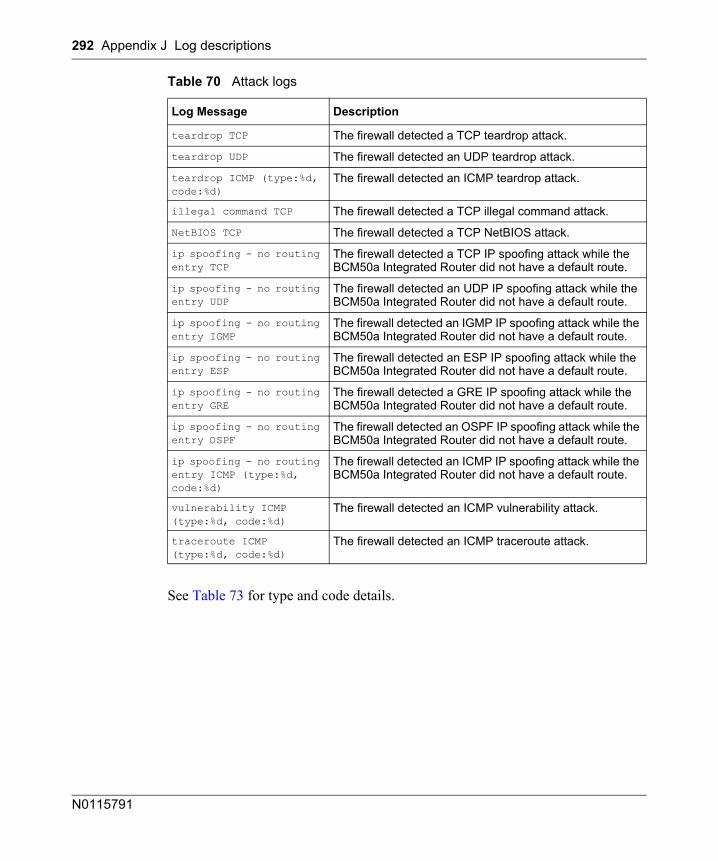
292 Appendix J Log descriptions
N0115791
See Table 73 for type and code details.
teardrop TCP The firewall detected a TCP teardrop attack.
teardrop UDP The firewall detected an UDP teardrop attack.
teardrop ICMP (type:%d, code:%d)
The firewall detected an ICMP teardrop attack.
illegal command TCP The firewall detected a TCP illegal command attack.
NetBIOS TCP The firewall detected a TCP NetBIOS attack.
ip spoofing - no routing entry TCP
The firewall detected a TCP IP spoofing attack while the BCM50a Integrated Router did not have a default route.
ip spoofing - no routing entry UDP
The firewall detected an UDP IP spoofing attack while the BCM50a Integrated Router did not have a default route.
ip spoofing - no routing entry IGMP
The firewall detected an IGMP IP spoofing attack while the BCM50a Integrated Router did not have a default route.
ip spoofing - no routing entry ESP
The firewall detected an ESP IP spoofing attack while the BCM50a Integrated Router did not have a default route.
ip spoofing - no routing entry GRE
The firewall detected a GRE IP spoofing attack while the BCM50a Integrated Router did not have a default route.
ip spoofing - no routing entry OSPF
The firewall detected an OSPF IP spoofing attack while the BCM50a Integrated Router did not have a default route.
ip spoofing - no routing entry ICMP (type:%d, code:%d)
The firewall detected an ICMP IP spoofing attack while the BCM50a Integrated Router did not have a default route.
vulnerability ICMP (type:%d, code:%d)
The firewall detected an ICMP vulnerability attack.
traceroute ICMP (type:%d, code:%d)
The firewall detected an ICMP traceroute attack.
Table 70 Attack logs
Log Message Description
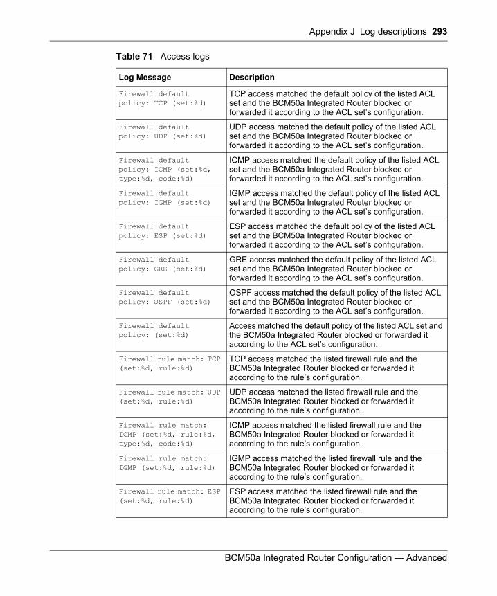
Appendix J Log descriptions 293
BCM50a Integrated Router Configuration — Advanced
Table 71 Access logs
Log Message Description
Firewall default policy: TCP (set:%d)
TCP access matched the default policy of the listed ACL set and the BCM50a Integrated Router blocked or forwarded it according to the ACL set’s configuration.
Firewall default policy: UDP (set:%d)
UDP access matched the default policy of the listed ACL set and the BCM50a Integrated Router blocked or forwarded it according to the ACL set’s configuration.
Firewall default policy: ICMP (set:%d, type:%d, code:%d)
ICMP access matched the default policy of the listed ACL set and the BCM50a Integrated Router blocked or forwarded it according to the ACL set’s configuration.
Firewall default policy: IGMP (set:%d)
IGMP access matched the default policy of the listed ACL set and the BCM50a Integrated Router blocked or forwarded it according to the ACL set’s configuration.
Firewall default policy: ESP (set:%d)
ESP access matched the default policy of the listed ACL set and the BCM50a Integrated Router blocked or forwarded it according to the ACL set’s configuration.
Firewall default policy: GRE (set:%d)
GRE access matched the default policy of the listed ACL set and the BCM50a Integrated Router blocked or forwarded it according to the ACL set’s configuration.
Firewall default policy: OSPF (set:%d)
OSPF access matched the default policy of the listed ACL set and the BCM50a Integrated Router blocked or forwarded it according to the ACL set’s configuration.
Firewall default policy: (set:%d)
Access matched the default policy of the listed ACL set and the BCM50a Integrated Router blocked or forwarded it according to the ACL set’s configuration.
Firewall rule match: TCP (set:%d, rule:%d)
TCP access matched the listed firewall rule and the BCM50a Integrated Router blocked or forwarded it according to the rule’s configuration.
Firewall rule match: UDP (set:%d, rule:%d)
UDP access matched the listed firewall rule and the BCM50a Integrated Router blocked or forwarded it according to the rule’s configuration.
Firewall rule match: ICMP (set:%d, rule:%d, type:%d, code:%d)
ICMP access matched the listed firewall rule and the BCM50a Integrated Router blocked or forwarded it according to the rule’s configuration.
Firewall rule match: IGMP (set:%d, rule:%d)
IGMP access matched the listed firewall rule and the BCM50a Integrated Router blocked or forwarded it according to the rule’s configuration.
Firewall rule match: ESP (set:%d, rule:%d)
ESP access matched the listed firewall rule and the BCM50a Integrated Router blocked or forwarded it according to the rule’s configuration.
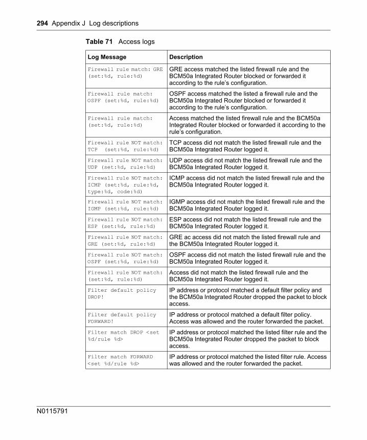
294 Appendix J Log descriptions
N0115791
Firewall rule match: GRE (set:%d, rule:%d)
GRE access matched the listed firewall rule and the BCM50a Integrated Router blocked or forwarded it according to the rule’s configuration.
Firewall rule match: OSPF (set:%d, rule:%d)
OSPF access matched the listed a firewall rule and the BCM50a Integrated Router blocked or forwarded it according to the rule’s configuration.
Firewall rule match: (set:%d, rule:%d)
Access matched the listed firewall rule and the BCM50a Integrated Router blocked or forwarded it according to the rule’s configuration.
Firewall rule NOT match: TCP (set:%d, rule:%d)
TCP access did not match the listed firewall rule and the BCM50a Integrated Router logged it.
Firewall rule NOT match: UDP (set:%d, rule:%d)
UDP access did not match the listed firewall rule and the BCM50a Integrated Router logged it.
Firewall rule NOT match: ICMP (set:%d, rule:%d, type:%d, code:%d)
ICMP access did not match the listed firewall rule and the BCM50a Integrated Router logged it.
Firewall rule NOT match: IGMP (set:%d, rule:%d)
IGMP access did not match the listed firewall rule and the BCM50a Integrated Router logged it.
Firewall rule NOT match: ESP (set:%d, rule:%d)
ESP access did not match the listed firewall rule and the BCM50a Integrated Router logged it.
Firewall rule NOT match: GRE (set:%d, rule:%d)
GRE ac access did not match the listed firewall rule and the BCM50a Integrated Router logged it.
Firewall rule NOT match: OSPF (set:%d, rule:%d)
OSPF access did not match the listed firewall rule and the BCM50a Integrated Router logged it.
Firewall rule NOT match: (set:%d, rule:%d)
Access did not match the listed firewall rule and the BCM50a Integrated Router logged it.
Filter default policy DROP!
IP address or protocol matched a default filter policy and the BCM50a Integrated Router dropped the packet to block access.
Filter default policy FORWARD!
IP address or protocol matched a default filter policy. Access was allowed and the router forwarded the packet.
Filter match DROP <set %d/rule %d>
IP address or protocol matched the listed filter rule and the BCM50a Integrated Router dropped the packet to block access.
Filter match FORWARD <set %d/rule %d>
IP address or protocol matched the listed filter rule. Access was allowed and the router forwarded the packet.
Table 71 Access logs
Log Message Description
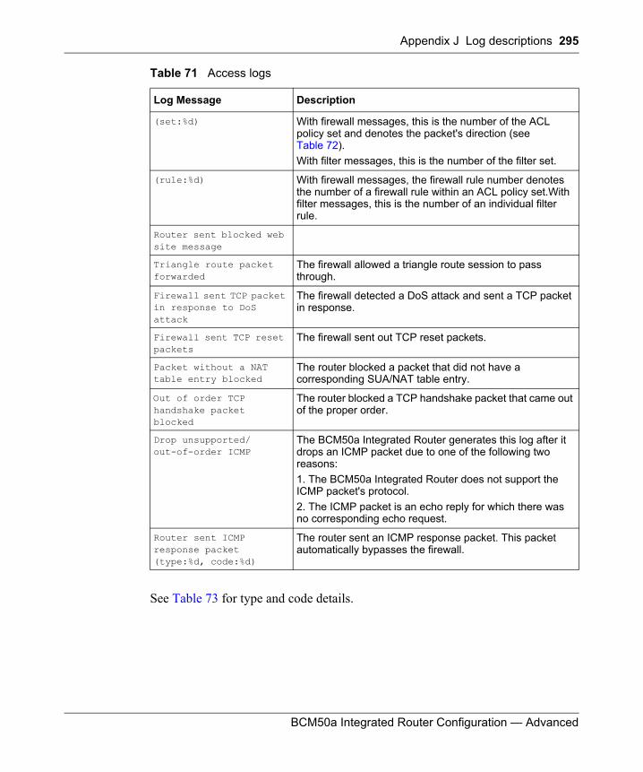
Appendix J Log descriptions 295
BCM50a Integrated Router Configuration — Advanced
See Table 73 for type and code details.
(set:%d) With firewall messages, this is the number of the ACL policy set and denotes the packet's direction (see Table 72).With filter messages, this is the number of the filter set.
(rule:%d) With firewall messages, the firewall rule number denotes the number of a firewall rule within an ACL policy set.With filter messages, this is the number of an individual filter rule.
Router sent blocked web site message
Triangle route packet forwarded
The firewall allowed a triangle route session to pass through.
Firewall sent TCP packet in response to DoS attack
The firewall detected a DoS attack and sent a TCP packet in response.
Firewall sent TCP reset packets
The firewall sent out TCP reset packets.
Packet without a NAT table entry blocked
The router blocked a packet that did not have a corresponding SUA/NAT table entry.
Out of order TCP handshake packet blocked
The router blocked a TCP handshake packet that came out of the proper order.
Drop unsupported/out-of-order ICMP
The BCM50a Integrated Router generates this log after it drops an ICMP packet due to one of the following two reasons: 1. The BCM50a Integrated Router does not support the ICMP packet's protocol.2. The ICMP packet is an echo reply for which there was no corresponding echo request.
Router sent ICMP response packet (type:%d, code:%d)
The router sent an ICMP response packet. This packet automatically bypasses the firewall.
Table 71 Access logs
Log Message Description
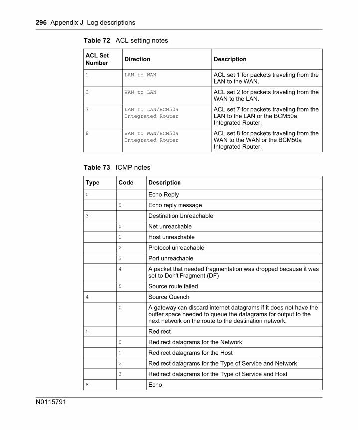
296 Appendix J Log descriptions
N0115791
Table 72 ACL setting notes
ACL Set Number Direction Description
1 LAN to WAN ACL set 1 for packets traveling from the LAN to the WAN.
2 WAN to LAN ACL set 2 for packets traveling from the WAN to the LAN.
7 LAN to LAN/BCM50a Integrated Router
ACL set 7 for packets traveling from the LAN to the LAN or the BCM50a Integrated Router.
8 WAN to WAN/BCM50a Integrated Router
ACL set 8 for packets traveling from the WAN to the WAN or the BCM50a Integrated Router.
Table 73 ICMP notes
Type Code Description
0 Echo Reply
0 Echo reply message
3 Destination Unreachable
0 Net unreachable
1 Host unreachable
2 Protocol unreachable
3 Port unreachable
4 A packet that needed fragmentation was dropped because it was set to Don't Fragment (DF)
5 Source route failed
4 Source Quench
0 A gateway can discard internet datagrams if it does not have the buffer space needed to queue the datagrams for output to the next network on the route to the destination network.
5 Redirect
0 Redirect datagrams for the Network
1 Redirect datagrams for the Host
2 Redirect datagrams for the Type of Service and Network
3 Redirect datagrams for the Type of Service and Host
8 Echo
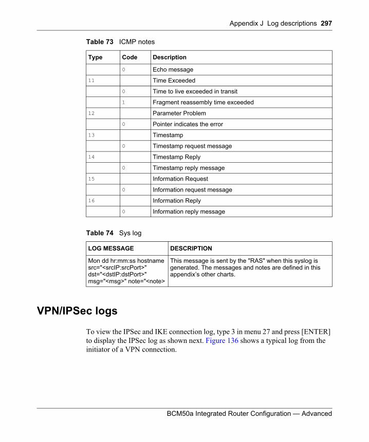
Appendix J Log descriptions 297
BCM50a Integrated Router Configuration — Advanced
VPN/IPSec logs
To view the IPSec and IKE connection log, type 3 in menu 27 and press [ENTER] to display the IPSec log as shown next. Figure 136 shows a typical log from the initiator of a VPN connection.
0 Echo message
11 Time Exceeded
0 Time to live exceeded in transit
1 Fragment reassembly time exceeded
12 Parameter Problem
0 Pointer indicates the error
13 Timestamp
0 Timestamp request message
14 Timestamp Reply
0 Timestamp reply message
15 Information Request
0 Information request message
16 Information Reply
0 Information reply message
Table 74 Sys log
LOG MESSAGE DESCRIPTION
Mon dd hr:mm:ss hostname src="<srcIP:srcPort>" dst="<dstIP:dstPort>" msg="<msg>" note="<note>
This message is sent by the "RAS" when this syslog is generated. The messages and notes are defined in this appendix’s other charts.
Table 73 ICMP notes
Type Code Description
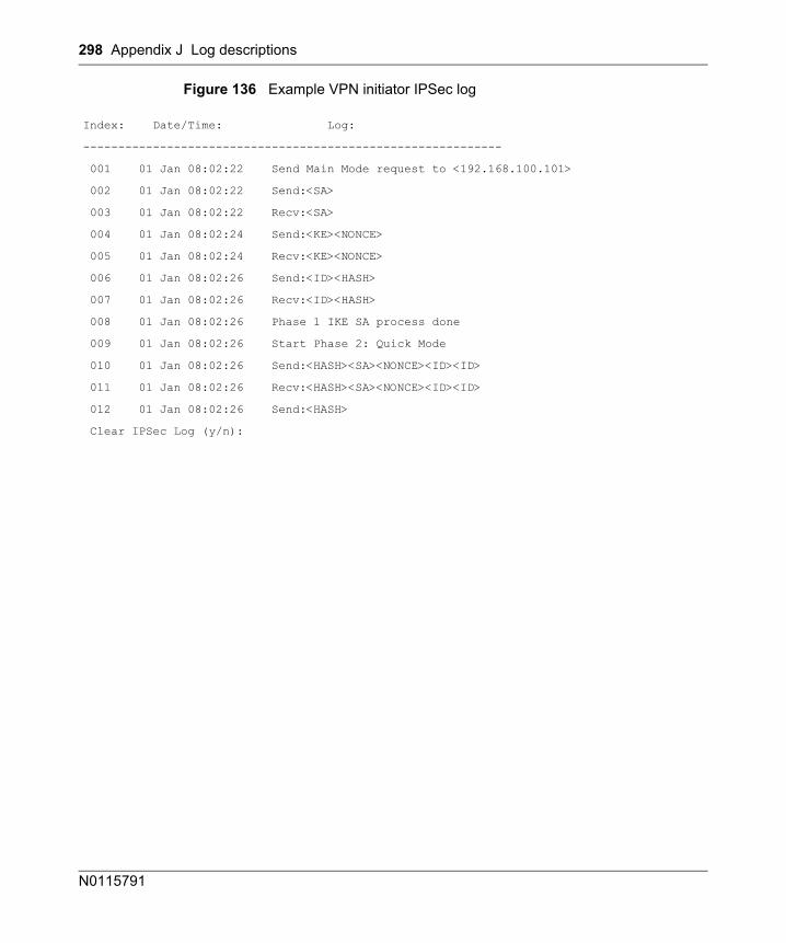
298 Appendix J Log descriptions
N0115791
Figure 136 Example VPN initiator IPSec log
Index: Date/Time: Log:
------------------------------------------------------------
001 01 Jan 08:02:22 Send Main Mode request to <192.168.100.101>
002 01 Jan 08:02:22 Send:<SA>
003 01 Jan 08:02:22 Recv:<SA>
004 01 Jan 08:02:24 Send:<KE><NONCE>
005 01 Jan 08:02:24 Recv:<KE><NONCE>
006 01 Jan 08:02:26 Send:<ID><HASH>
007 01 Jan 08:02:26 Recv:<ID><HASH>
008 01 Jan 08:02:26 Phase 1 IKE SA process done
009 01 Jan 08:02:26 Start Phase 2: Quick Mode
010 01 Jan 08:02:26 Send:<HASH><SA><NONCE><ID><ID>
011 01 Jan 08:02:26 Recv:<HASH><SA><NONCE><ID><ID>
012 01 Jan 08:02:26 Send:<HASH>
Clear IPSec Log (y/n):
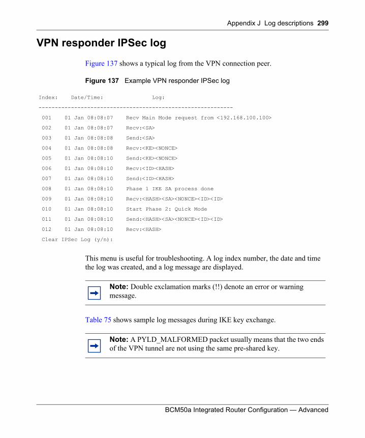
Appendix J Log descriptions 299
BCM50a Integrated Router Configuration — Advanced
VPN responder IPSec log
Figure 137 shows a typical log from the VPN connection peer.
Figure 137 Example VPN responder IPSec log
This menu is useful for troubleshooting. A log index number, the date and time the log was created, and a log message are displayed.
Table 75 shows sample log messages during IKE key exchange.
Index: Date/Time: Log:
------------------------------------------------------------
001 01 Jan 08:08:07 Recv Main Mode request from <192.168.100.100>
002 01 Jan 08:08:07 Recv:<SA>
003 01 Jan 08:08:08 Send:<SA>
004 01 Jan 08:08:08 Recv:<KE><NONCE>
005 01 Jan 08:08:10 Send:<KE><NONCE>
006 01 Jan 08:08:10 Recv:<ID><HASH>
007 01 Jan 08:08:10 Send:<ID><HASH>
008 01 Jan 08:08:10 Phase 1 IKE SA process done
009 01 Jan 08:08:10 Recv:<HASH><SA><NONCE><ID><ID>
010 01 Jan 08:08:10 Start Phase 2: Quick Mode
011 01 Jan 08:08:10 Send:<HASH><SA><NONCE><ID><ID>
012 01 Jan 08:08:10 Recv:<HASH>
Clear IPSec Log (y/n):
Note: Double exclamation marks (!!) denote an error or warning message.
Note: A PYLD_MALFORMED packet usually means that the two ends of the VPN tunnel are not using the same pre-shared key.
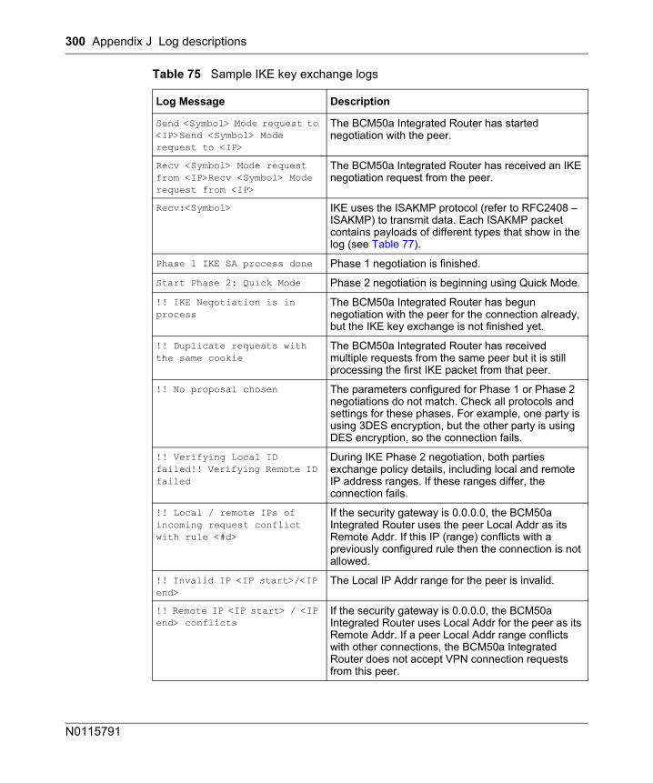
300 Appendix J Log descriptions
N0115791
Table 75 Sample IKE key exchange logs
Log Message Description
Send <Symbol> Mode request to <IP>Send <Symbol> Mode request to <IP>
The BCM50a Integrated Router has started negotiation with the peer.
Recv <Symbol> Mode request from <IP>Recv <Symbol> Mode request from <IP>
The BCM50a Integrated Router has received an IKE negotiation request from the peer.
Recv:<Symbol> IKE uses the ISAKMP protocol (refer to RFC2408 – ISAKMP) to transmit data. Each ISAKMP packet contains payloads of different types that show in the log (see Table 77).
Phase 1 IKE SA process done Phase 1 negotiation is finished.
Start Phase 2: Quick Mode Phase 2 negotiation is beginning using Quick Mode.
!! IKE Negotiation is in process
The BCM50a Integrated Router has begun negotiation with the peer for the connection already, but the IKE key exchange is not finished yet.
!! Duplicate requests with the same cookie
The BCM50a Integrated Router has received multiple requests from the same peer but it is still processing the first IKE packet from that peer.
!! No proposal chosen The parameters configured for Phase 1 or Phase 2 negotiations do not match. Check all protocols and settings for these phases. For example, one party is using 3DES encryption, but the other party is using DES encryption, so the connection fails.
!! Verifying Local ID failed!! Verifying Remote ID failed
During IKE Phase 2 negotiation, both parties exchange policy details, including local and remote IP address ranges. If these ranges differ, the connection fails.
!! Local / remote IPs of incoming request conflict with rule <#d>
If the security gateway is 0.0.0.0, the BCM50a Integrated Router uses the peer Local Addr as its Remote Addr. If this IP (range) conflicts with a previously configured rule then the connection is not allowed.
!! Invalid IP <IP start>/<IP end>
The Local IP Addr range for the peer is invalid.
!! Remote IP <IP start> / <IP end> conflicts
If the security gateway is 0.0.0.0, the BCM50a Integrated Router uses Local Addr for the peer as its Remote Addr. If a peer Local Addr range conflicts with other connections, the BCM50a Integrated Router does not accept VPN connection requests from this peer.
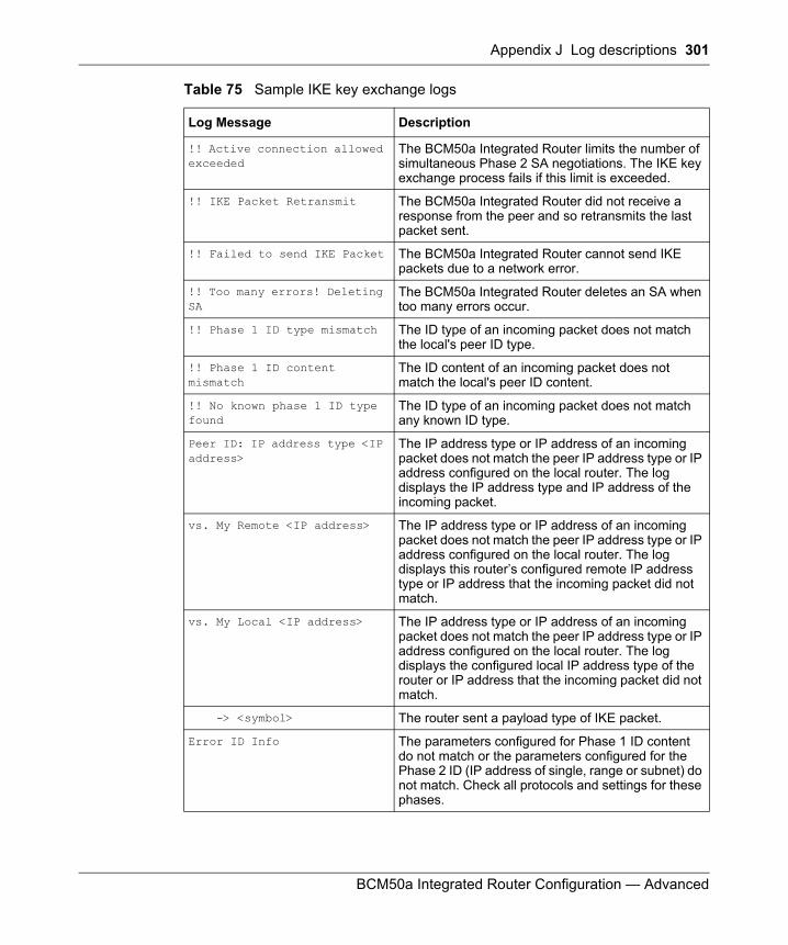
Appendix J Log descriptions 301
BCM50a Integrated Router Configuration — Advanced
!! Active connection allowed exceeded
The BCM50a Integrated Router limits the number of simultaneous Phase 2 SA negotiations. The IKE key exchange process fails if this limit is exceeded.
!! IKE Packet Retransmit The BCM50a Integrated Router did not receive a response from the peer and so retransmits the last packet sent.
!! Failed to send IKE Packet The BCM50a Integrated Router cannot send IKE packets due to a network error.
!! Too many errors! Deleting SA
The BCM50a Integrated Router deletes an SA when too many errors occur.
!! Phase 1 ID type mismatch The ID type of an incoming packet does not match the local's peer ID type.
!! Phase 1 ID content mismatch
The ID content of an incoming packet does not match the local's peer ID content.
!! No known phase 1 ID type found
The ID type of an incoming packet does not match any known ID type.
Peer ID: IP address type <IP address>
The IP address type or IP address of an incoming packet does not match the peer IP address type or IP address configured on the local router. The log displays the IP address type and IP address of the incoming packet.
vs. My Remote <IP address> The IP address type or IP address of an incoming packet does not match the peer IP address type or IP address configured on the local router. The log displays this router’s configured remote IP address type or IP address that the incoming packet did not match.
vs. My Local <IP address> The IP address type or IP address of an incoming packet does not match the peer IP address type or IP address configured on the local router. The log displays the configured local IP address type of the router or IP address that the incoming packet did not match.
-> <symbol> The router sent a payload type of IKE packet.
Error ID Info The parameters configured for Phase 1 ID content do not match or the parameters configured for the Phase 2 ID (IP address of single, range or subnet) do not match. Check all protocols and settings for these phases.
Table 75 Sample IKE key exchange logs
Log Message Description
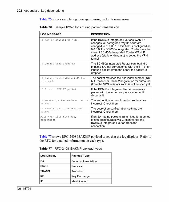
302 Appendix J Log descriptions
N0115791
Table 76 shows sample log messages during packet transmission.
Table 77 shows RFC-2408 ISAKMP payload types that the log displays. Refer to the RFC for detailed information on each type.
Table 76 Sample IPSec logs during packet transmission
LOG MESSAGE DESCRIPTION
!! WAN IP changed to <IP> If the BCM50a Integrated Router’s WAN IP changes, all configured “My IP Addr” are changed to “0.0.0.0”. If this field is configured as 0.0.0.0, the BCM50a Integrated Router uses the current BCM50a Integrated Router WAN IP address (static or dynamic) to set up the VPN tunnel.
!! Cannot find IPSec SA The BCM50a Integrated Router cannot find a phase 2 SA that corresponds with the SPI of an inbound packet (from the peer); the packet is dropped.
!! Cannot find outbound SA for rule <%d>
The packet matches the rule index number (#d), but Phase 1 or Phase 2 negotiation for outbound (from the VPN initiator) traffic is not finished yet.
!! Discard REPLAY packet If the BCM50a Integrated Router receives a packet with the wrong sequence number it discards it.
!! Inbound packet authentication failed
The authentication configuration settings are incorrect. Check them.
!! Inbound packet decryption failed
The decryption configuration settings are incorrect. Check them.
Rule <#d> idle time out, disconnect
If an SA has no packets transmitted for a period of time (configurable via CI command), the BCM50a Integrated Router drops the connection.
Table 77 RFC-2408 ISAKMP payload types
Log Display Payload Type
SA Security Association
PROP Proposal
TRANS Transform
KE Key Exchange
ID Identification
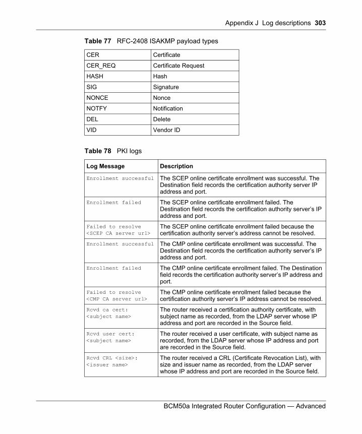
Appendix J Log descriptions 303
BCM50a Integrated Router Configuration — Advanced
CER Certificate
CER_REQ Certificate Request
HASH Hash
SIG Signature
NONCE Nonce
NOTFY Notification
DEL Delete
VID Vendor ID
Table 78 PKI logs
Log Message Description
Enrollment successful The SCEP online certificate enrollment was successful. The Destination field records the certification authority server IP address and port.
Enrollment failed The SCEP online certificate enrollment failed. The Destination field records the certification authority server’s IP address and port.
Failed to resolve <SCEP CA server url>
The SCEP online certificate enrollment failed because the certification authority server’s address cannot be resolved.
Enrollment successful The CMP online certificate enrollment was successful. The Destination field records the certification authority server’s IP address and port.
Enrollment failed The CMP online certificate enrollment failed. The Destination field records the certification authority server’s IP address and port.
Failed to resolve <CMP CA server url>
The CMP online certificate enrollment failed because the certification authority server’s IP address cannot be resolved.
Rcvd ca cert: <subject name>
The router received a certification authority certificate, with subject name as recorded, from the LDAP server whose IP address and port are recorded in the Source field.
Rcvd user cert: <subject name>
The router received a user certificate, with subject name as recorded, from the LDAP server whose IP address and port are recorded in the Source field.
Rcvd CRL <size>: <issuer name>
The router received a CRL (Certificate Revocation List), with size and issuer name as recorded, from the LDAP server whose IP address and port are recorded in the Source field.
Table 77 RFC-2408 ISAKMP payload types
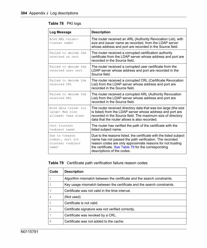
304 Appendix J Log descriptions
N0115791
Rcvd ARL <size>: <issuer name>
The router received an ARL (Authority Revocation List), with size and issuer name as recorded, from the LDAP server whose address and port are recorded in the Source field.
Failed to decode the received ca cert
The router received a corrupted certification authority certificate from the LDAP server whose address and port are recorded in the Source field.
Failed to decode the received user cert
The router received a corrupted user certificate from the LDAP server whose address and port are recorded in the Source field.
Failed to decode the received CRL
The router received a corrupted CRL (Certificate Revocation List) from the LDAP server whose address and port are recorded in the Source field.
Failed to decode the received ARL
The router received a corrupted ARL (Authority Revocation List) from the LDAP server whose address and port are recorded in the Source field.
Rcvd data <size> too large! Max size allowed: <max size>
The router received directory data that was too large (the size is listed) from the LDAP server whose address and port are recorded in the Source field. The maximum size of directory data that the router allows is also recorded.
Cert trusted: <subject name>
The router has verified the path of the certificate with the listed subject name.
Due to <reason codes>, cert not trusted: <subject name>
Due to the reasons listed, the certificate with the listed subject name has not passed the path verification. The recorded reason codes are only approximate reasons for not trusting the certificate. See Table 79 for the corresponding descriptions of the codes.
Table 79 Certificate path verification failure reason codes
Code Description
1 Algorithm mismatch between the certificate and the search constraints.
2 Key usage mismatch between the certificate and the search constraints.
3 Certificate was not valid in the time interval.
4 (Not used)
5 Certificate is not valid.
6 Certificate signature was not verified correctly.
7 Certificate was revoked by a CRL.
8 Certificate was not added to the cache.
Table 78 PKI logs
Log Message Description
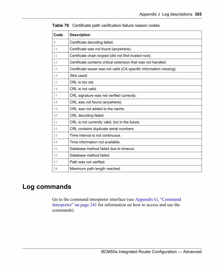
Appendix J Log descriptions 305
BCM50a Integrated Router Configuration — Advanced
Log commands
Go to the command interpreter interface (see Appendix G, “Command Interpreter” on page 241 for information on how to access and use the commands).
9 Certificate decoding failed.
10 Certificate was not found (anywhere).
11 Certificate chain looped (did not find trusted root).
12 Certificate contains critical extension that was not handled.
13 Certificate issuer was not valid (CA specific information missing).
14 (Not used)
15 CRL is too old.
16 CRL is not valid.
17 CRL signature was not verified correctly.
18 CRL was not found (anywhere).
19 CRL was not added to the cache.
20 CRL decoding failed.
21 CRL is not currently valid, but in the future.
22 CRL contains duplicate serial numbers.
23 Time interval is not continuous.
24 Time information not available.
25 Database method failed due to timeout.
26 Database method failed.
27 Path was not verified.
28 Maximum path length reached.
Table 79 Certificate path verification failure reason codes
Code Description
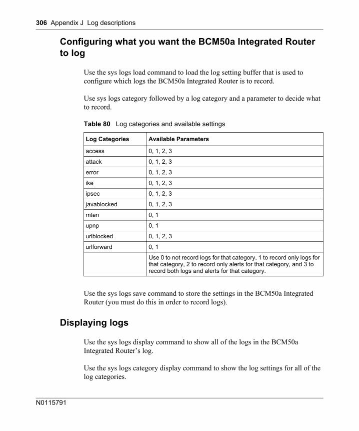
306 Appendix J Log descriptions
N0115791
Configuring what you want the BCM50a Integrated Router to log
Use the sys logs load command to load the log setting buffer that is used to configure which logs the BCM50a Integrated Router is to record.
Use sys logs category followed by a log category and a parameter to decide what to record.
Use the sys logs save command to store the settings in the BCM50a Integrated Router (you must do this in order to record logs).
Displaying logs
Use the sys logs display command to show all of the logs in the BCM50a Integrated Router’s log.
Use the sys logs category display command to show the log settings for all of the log categories.
Table 80 Log categories and available settings
Log Categories Available Parameters
access 0, 1, 2, 3
attack 0, 1, 2, 3
error 0, 1, 2, 3
ike 0, 1, 2, 3
ipsec 0, 1, 2, 3
javablocked 0, 1, 2, 3
mten 0, 1
upnp 0, 1
urlblocked 0, 1, 2, 3
urlforward 0, 1
Use 0 to not record logs for that category, 1 to record only logs for that category, 2 to record only alerts for that category, and 3 to record both logs and alerts for that category.
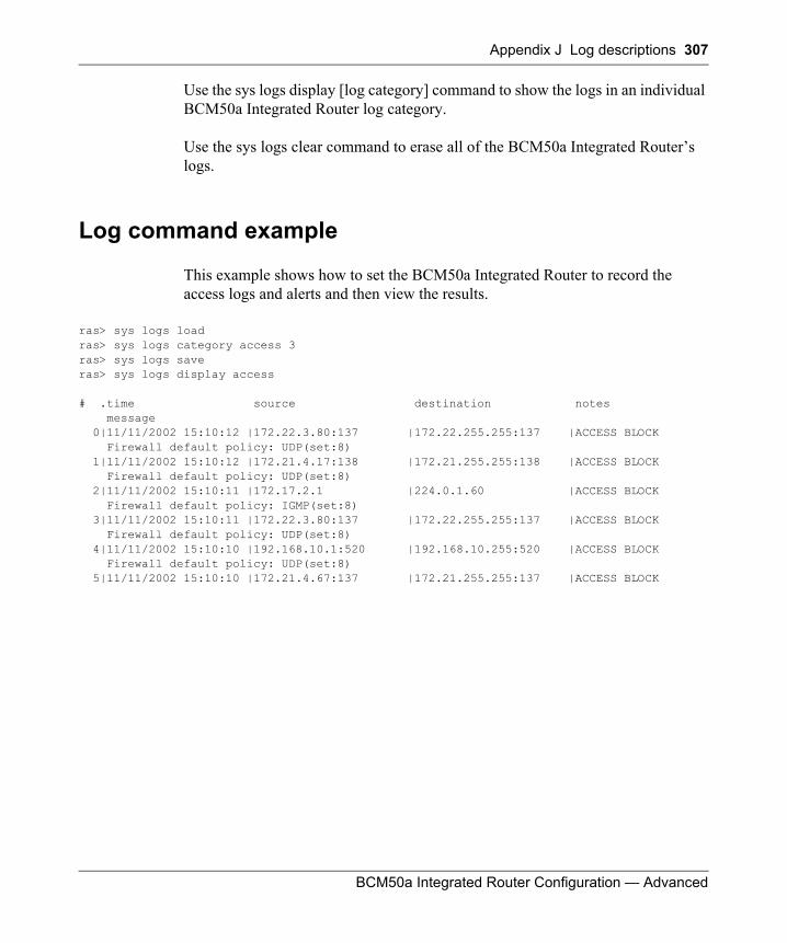
Appendix J Log descriptions 307
BCM50a Integrated Router Configuration — Advanced
Use the sys logs display [log category] command to show the logs in an individual BCM50a Integrated Router log category.
Use the sys logs clear command to erase all of the BCM50a Integrated Router’s logs.
Log command example
This example shows how to set the BCM50a Integrated Router to record the access logs and alerts and then view the results.
ras> sys logs loadras> sys logs category access 3ras> sys logs saveras> sys logs display access
# .time source destination notes message 0|11/11/2002 15:10:12 |172.22.3.80:137 |172.22.255.255:137 |ACCESS BLOCK Firewall default policy: UDP(set:8) 1|11/11/2002 15:10:12 |172.21.4.17:138 |172.21.255.255:138 |ACCESS BLOCK Firewall default policy: UDP(set:8) 2|11/11/2002 15:10:11 |172.17.2.1 |224.0.1.60 |ACCESS BLOCK Firewall default policy: IGMP(set:8) 3|11/11/2002 15:10:11 |172.22.3.80:137 |172.22.255.255:137 |ACCESS BLOCK Firewall default policy: UDP(set:8) 4|11/11/2002 15:10:10 |192.168.10.1:520 |192.168.10.255:520 |ACCESS BLOCK Firewall default policy: UDP(set:8) 5|11/11/2002 15:10:10 |172.21.4.67:137 |172.21.255.255:137 |ACCESS BLOCK

308 Appendix J Log descriptions
N0115791
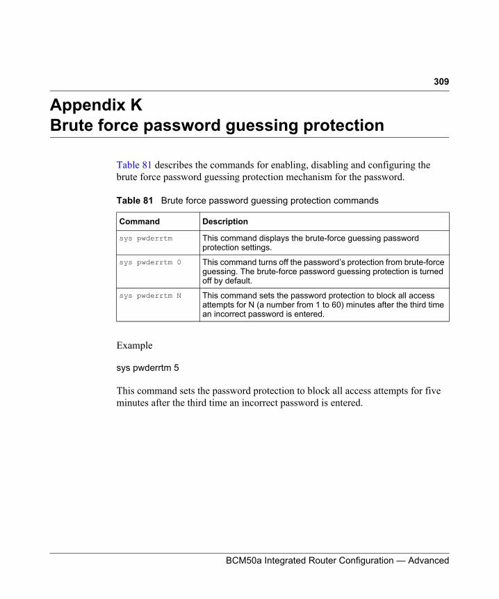
309
BCM50a Integrated Router Configuration — Advanced
Appendix KBrute force password guessing protection
Table 81 describes the commands for enabling, disabling and configuring the brute force password guessing protection mechanism for the password.
Example
sys pwderrtm 5
This command sets the password protection to block all access attempts for five minutes after the third time an incorrect password is entered.
Table 81 Brute force password guessing protection commands
Command Description
sys pwderrtm This command displays the brute-force guessing password protection settings.
sys pwderrtm 0 This command turns off the password’s protection from brute-force guessing. The brute-force password guessing protection is turned off by default.
sys pwderrtm N This command sets the password protection to block all access attempts for N (a number from 1 to 60) minutes after the third time an incorrect password is entered.

310 Appendix K Brute force password guessing protection
N0115791
BCM50a Integrated Router Configuration — Advanced
311
Index
Numbers4-Port Switch 31
AADSL standards 30Alternative Subnet Mask Notation 234Applications 37AT command 55, 162ATM Options 79Authentication 69, 73Authentication Protocol 69Autonegotiating 10/100 Mb/s Ethernet LAN 32Autosensing 10/100 Mb/s Ethernet LAN 32
BBackup 162Brute Force Password Guessing Protection 33Budget Management 178
CCall Control 177Call History 180Call Scheduling 34, 189
Maximum Number of Schedule Sets 189PPPoE 192Precedence 190Precedence Example 190
Call-Triggering Packet 156Central Network Management 35
CHAP 73CHAP/PAP 73Collision 148Command Interpreter Mode 175Community 137Conditions that prevent TFTP and FTP from
working over WAN 164Console Port 148, 149, 151Content Filtering 34Contivity VPN Client Software 32conventions, text 23copyright 2Cost Of Transmission 76CPU Load 148
DDDNS
Configuration 48DDNS Type 49Denial of Service 115DHCP 59DHCP (Dynamic Host Configuration Protocol) 36DHCP Ethernet Setup 58Diagnostic 157DoS (Denial of Service) 33Dynamic DNS Support 34
EEMAIL 49
312 Index
N0115791
E-mail Address 49Enable Wildcard 50Encapsulation 66, 71encapsulation 31Entering Information 41Ethernet Encapsulation 78
FF/W Version 162Features 29Filename Conventions 161Filter 77
Applying 134Configuration 117Configuring 120Example 130Generic Filter Rule 128Generic Rule 129NAT 133Remote Node 135Structure 118TCP/IP Rule 124
FiltersExecuting a Filter Rule 118IP Filter Logic Flow 126
Firewall 33Activating 115SMT Menus 115
FTP 187FTP File Transfer 169FTP Restrictions 164, 187FTP Server 37, 107Full Network Management 36
GGateway IP Address 85General Setup 45
HHidden Menus 40Hop Count 76Host 49Host IDs 232HTTPS 33
IIdle Timeout 70IGMP support 77Incoming Protocol Filters 63Initial Screen 39Internet Access 65, 66Internet access 30Internet Access Configuration 65Internet Access information 65Internet Access Setup 90Introduction to Filters 117IP Address 61, 62, 150IP Addressing 231IP Alias 35, 62IP Alias Setup 61, 62IP Classes 231IP Multicast 35
Internet Group Management Protocol (IGMP) 35
IP Pool 59, 60IP Static Route 83, 84, 85
Active 85Destination IP Address 85IP Subnet Mask 85Name 85Route Number 85
IP Subnet Mask 62IPSec VPN Capability 32, 33
Index 313
BCM50a Integrated Router Configuration — Advanced
LLAN 148LAN Port Filter Setup 57LAN Setup 57, 58LAN-to-LAN application 71Link type 147LLC 79LLC-based Multiplexing 79Log 151Log Facility 153Logging 36Logging In to the SMT 39Login Screen 39, 40
MMain Menu 41Mean Time Between Failures 229Metric 76, 85MTBF 229Multicast 61, 77Multiplexing 31, 66, 71multiplexing 79My WAN Address 76
NNailed-up Connection 70NAT 133
Applying NAT in the SMT Menus 89Configuring 92Examples 103Ordering Rules 96
Network Address Translation 67Network Address Translation (NAT) 35, 89
OOffline 50
Operation Temperature 229Outgoing Protocol Filters 63
PPacket
Error 147Received 148Transmitted 148
Packet Filtering 34Packets 147PAP 73Password 40, 43, 137Ping 159Port Forwarding 36PPP Encapsulation 79PPPoA 71PPPoE 34, 225PPPoE Encapsulation 70, 78Private 76, 86Protocol Filters 63
Incoming 63Outgoing 63
publicationshard copy 24related 24
RRate
Receiving 147Transmission 147
regulatory information 2Remote Management 185Remote Management Limitations 187Remote Node 69, 148
Remote Node Setup 70Remote Node Filter 77Remote Node Index Number 147
314 Index
N0115791
Required fields 41Reset Button 32Resetting the Time 184Restore Configuration 167RFC-1483 72RFC-2364 71RIP 61, 63, 76
Direction 63Version 63
SSchedule Sets
Duration 191Server 92, 95, 98, 99, 105, 106, 182setup a schedule 190SMT 40SNMP 35
Community 138Configuration 137Trusted Host 138
SNMP (Simple Network Management Protocol) 35
SSH 33Stateful Inspection 33SUA (Single User Account) 89Subnet Mask 61, 75, 85, 150Subnet Masks 233Subnetting 233Syslog 152Syslog IP Address 153System Information 145, 148, 149System Maintenance 145, 146, 147, 148, 150, 151,
152, 158, 159, 162, 165, 172, 175, 177, 178, 180, 182
System Management Terminal 40System Name 46System Status 146
TTCP/IP 58, 61, 123, 124, 126, 129, 133
Setup 61TCP/IP and DHCP Setup 58TCP/IP filter rule 123technical publications 24text conventions 23TFTP File Transfer 172TFTP Restrictions 164, 187Time and Date 32Time and Date Setting 181, 182Time Zone 183Trace 151Tracing 36trademarks 2Traffic Redirect 36
Setup 55Triangle 205Triangle Route Solutions 206Trigger Port Forwarding 111
UUniversal Plug and Play 34Upgradeable Firmware 37Upload Firmware 169UPnP 34User Name 49User Profiles 87Username 40
VVC 79VC-based Multiplexing 71Virtual Channel Identifier (VCI) 66Virtual Path Identifier (VPI) 66

Index 315
BCM50a Integrated Router Configuration — Advanced
WWAN DHCP 158, 159WAN Setup 53, 54WebGUI 116www.dyndns.org 50