bda section 11 - california department of · pdf file8/10/2004 · calculations for...
TRANSCRIPT

BRIDGE DESIGN AIDS • MARCH 2005
ESTIMATING
Introduction In accordance with the requirements of the State Contract Act, the State Highway Engineer must prepare full, complete, and accurate plans, specifications and estimates of cost before entering into any contract. The estimate, known as the “Engineers Estimate”, lists the total quantity and estimated price for each item, and is used as a basis for requesting authority to advertise a project. After bids are received, the Engineer’s Estimate is used as a basis for determining if the bid estimates are reasonable.
The Bridge Cost Estimates Branch provides the item costs for the Engineers Estimate for all bridge and highway related structures. This cost estimate data, along with the special provisions and contract plans, make up the Structure’s portion of the PS&E package.
General
BEES (Basic Engineering Estimate System) The bridge portion of the Engineers Estimate is entered into Basic Engineering Estimate System or BEES by SOE, Bridge Cost Estimates Branch. BEES is a computer program used for storing estimated quantities and prices for each item of the project. The bridge portion of the estimate is placed in the B (bridge) file and the Districts enter their portion of the estimate in the H (highway) file. The BEES computer program then generates the C (combined) estimate for the entire project.
BEES has the capability of segregating estimates by structure, alternative designs, etc. BEES segregation is performed by the District. BEES is a sub-system of the Project Information System and Analysis (PISA) and utilizes the information contained in the Project Management Control System (PMCS) and the Standardized Item List. The estimate data is available for bid opening purposes and for contract progress payments.
Revised Estimates When any changes such as quantity, cost, or scope of work are made it is the responsibility of the Design Branch Leader and Project Engineer to advise all interested parties as successive estimates are made during the development of a project.
ESTIMATING 11-1

BRIDGE DESIGN AIDS • MARCH 2005
Quantity Calculations Quantity calculations are to be submitted to the Bridge Cost Estimates Branch along with the Estimate Summary sheets. Calculations for Marginal “Blue Sheet” Estimates are retained in Cost Estimates Branch until the contract is awarded, at which time they are forwarded to the Resident Engineer’s Pending File for the Structure Representative’s use during the course of construction.
Escalation Factor Structure estimates are prepared on the basis of prices which are valid on the day the estimate is made. As part of their procedure in developing their planning program, the Districts periodically apply an escalation factor according to the cost index to these estimates as necessary to cover inflation.
Mobilization Factor Structure estimates generally include an item for mobilization. The value of this item is estimated at 10% of the total cost of bid items. If a particular kind or size of a project does not require a separate item for mobilization, the unit price for one or more of the major items of work will be inflated to cover the contractors cost for mobilization.
Contingency Factors A contingency factor is added to all estimates to cover the costs of unforeseen design changes and the uncertainty of early quantity estimates. Contingency factors are shown below:
Planning Estimates 25% Contingency
General Plan Estimates 20% Contingency
Marginal Estimate – Final PS&E 5% Contingency
Stage Construction It is sometimes necessary to build a bridge in stages. The most common case is replacing a bridge on existing alignment. This will increase the cost about 25% and the construction time about 75%. The plans must show the width of each stage and indicate how traffic is to be handled during each stage of construction.
11-2 ESTIMATING

BRIDGE DESIGN AIDS • MARCH 2005
Traffic Control This item of work is defined and estimated by the Districts. However, it is important that the bridge designer understands how traffic will affect the work and relay this information to Cost Estimates either verbally or by notes on the plans or estimate. At the Plans and Quanties (P&Q) stage of project delivery, all traffic considerations shall be included in the memo to specifications engineer/estimator. Usual situations are “Work 9 AM – 3 PM only” or “All work at night or on weekends.” This and other items concerning work in traffic should be discussed with the District Project Engineer at an early stage. More expensive types of work that can be done quickly without traffic control may be justified by the savings in traffic control costs. Design shall submit lane closure charts when available to cost estimates.
Working Days The Cost Estimates Branch determines the number of working days necessary to construct the bridge portion of the contract work for PS&E. Design shall submit information regarding restrictions and constraints to cost estimates. At the District’s request, working days will be provided for Advanced Planning and General Plan stages.
Historical Cost Record This form is to be used by the Project Engineer to maintain a cost record for all structures in the design phase. It is designed for multi-structure projects, but can also be used for individual structures. The Project Engineer is usually the only one familiar with the reason for revisions and related cost changes. Explain these on the back of the form. A copy of the Historical Cost Record form (DS-D-0001) available on the Cost Estimates Branch website:
http://www.dot.ca.gov/hq/esc/estimates/
Design Branch Leaders are responsible for assuring that the cost record and the Status agree.
Cost changes that are a result of price changes made by Cost Estimates are also to be recorded.
ESTIMATING 11-3

BRIDGE DESIGN AIDS • MARCH 2005
Planning Estimates (Advance Planning Studies) These preliminary estimates are usually based on District geometrics and are used to determine the overall project cost for budgeting purposes. Design prepares a drawing of the structure, called an “Advanced Planning Study”, which shows all significant details that would affect the cost (See Memo to Designers 1-8). Design shall then submit a completed advance planning study and general plan estimate checklist for each planning estimate.
For usual or normal types of new bridge structures, the Cost Estimates Branch will determine the quantities using their file of square meter factors.
For unusual structures such as retaining walls, seismic retrofits, barrier replacements, sliver widenings of less than five meters in width, deck rehabilitations, or in cases where a close comparison of costs of several different types of structures are required, the designer computes preliminary quantities using any of the aids found in this chapter and submits them along with a completed Bridge Planning Estimate form (DS - D - 0016) and Structure plan sheet to the Cost Estimate.
Current Planning Estimate forms may be downloaded from the Cost Estimates Branch website:
http://www.dot.ca.gov/hq/esc/estimates/
General Plan Estimates The District develops the precise alignment and submits the bridge site data to Preliminary Investigations. The bridge site data is incorporated into the Preliminary Report which is ultimately forwarded to Bridge Design. Bridge Design chooses the most feasible and usually the most economical type of structure to fit the conditions described in the Preliminary Report and then develops a General Plan. The structure depicted in the General Plan may be different from the structure used for the Planning Estimate.
From the General Plan an estimate of cost is determined by the Cost Estimates Branch from quantities calculated by Bridge Design.
The preparation of quantities for General Plan Estimates requires a rapid but close approximation of the final quantities for the job. All items which are a part of the cost of the bridge should be included in the estimate.
In preparing the quantities, the quantity estimator utilizes the graphs and tables prepared for this purpose, similar jobs, or computations based on dimensions from the preliminary design.
Current General Plan Estimate forms may be downloaded from the Cost Estimates Branch website:
http://www.dot.ca.gov/hq/esc/estimates/
11-4 ESTIMATING

BRIDGE DESIGN AIDS • MARCH 2005
Bar Reinforcement /m3 of Concrete for Various Bridge Parts The following are approximate quantities of Bar Reinforcement per cubic meter of concrete. Use for Planning and General Plan Estimates only. Deck slab on prestressed or steel girders ................................................................... 134 kg/m³ Bent Caps ...................................................................................................................... 90 kg/m³ Single column bents ..................................................................... 268 kg/m³ (170-324 variation) Multiple column bents .................................................................... 134 kg/m³ (57-208 variation) Piers and walls of simulated closed end abutments ...................................................... 48 kg/m³ Footings ...................................................................................................................90-119 kg/m³ End diaphragm abutments ............................................................................................. 48 kg/m³ Cantilever and strutted abutments ........................................................................ Design Charts Retaining walls .........................................................................................................Page 11- 49 Seat Type Abutments Skews < 15° ........................................................................ 54 kg/m³ Skews 15° to 45° ............................................................................................. 60 - 83 kg/m³ Bar Reinforcement/m² of Deck Area Cast-In-Place Reinforced Slab ...................................................................................... 64 kg/m2
Note: See “Sources of Quantities for Standard Details” shown in SECTION 11.
ESTIMATING 11-5

BRIDGE DESIGN AIDS • MARCH 2005
Type 1 Retaining Wall Excavation and Backfill Quantities Per linear meter in m³
Use for Planning and General Plan Estimates only
H Level 1 1 /2 : 1 2 : 1
Height at Face Excav Backfill Height
at Face Excav Backfill Height at Face Excav Backfill
mm mm m3/m m3/m mm m3/m m3/m mm m3/m m3/m
1200 1000 1.60 0.84 1500 2.43 1.17 1200 2.05 1.09
1800 1000 1.90 1.56 1500 2.98 2.04 1200 2.50 1.92
2400 1000 2.20 2.51 1500 3.55 3.16 1300 3.11 3.00
3000 1000 2.50 3.68 1600 4.31 4.53 140 3.78 4.32
3600 1000 2.80 4.98 1700 5.14 6.06 1500 4.51 5.79
4200 1100 3.30 6.34 1800 5.93 7.61 1600 5.23 7.29
4800 1100 3.63 8.15 1900 6.89 9.69 1700 6.07 9.31
5500 1200 4.19 10.37 2000 7.91 12.21 1800 6.98 11.75
6100 1200 4.53 12.65 2100 8.99 14.82 1900 7.94 14.28
6700 1300 5.29 15.36 2200 10.42 17.97 2000 9.21 17.32
7300 1400 6.10 17.73 2300 11.80 20.73 2100 10.45 19.98
7900 1500 6.99 20.05 2400 13.28 23.46 2200 11.79 22.61
8500 1600 7.94 22.84 2500 14.85 26.69 2300 13.21 25.73
9100 1700 9.20 26.60 2600 17.27 31.29 2400 15.34 30.12
9700 1800 10.74 30.43 2700 20.03 36.03 2500 17.81 34.63
10300 1900 11.91 33.77 2900 22.37 39.93 2600 19.54 38.39
10900 2000 13.14 37.28 3000 24.39 44.03 2700 21.35 42.34
300300
600
300
600
300 300
600
300
1 1 / 2:1 or 2:1
1 1 / 2:1 or 2:1
Height at face of wall
Height at face of wall
Level
Level
Excavation Backfill Excavation Backfill
11-6 ESTIMATING

BRIDGE DESIGN AIDS • MARCH 2005
0.30
0.35
0.40
0.45
0.50
0.55
0.60
0.65
0.25
m3 per m2 of Deck
2.25
m
2.00
m
1.75
m
1.50
m
1.25
m
1.00
m D
epth
No
te:
Ben
t ca
ps
and
Hin
ges
are
no
tin
clu
ded
in t
hes
e q
uan
titi
esSt
em w
idth
= 3
55 m
mG
ird
er S
pac
ing
= 2
.0 m
to 2
.5 m
DW
D=
Bri
dg
eW
= "
Dec
k w
idth
Use
for P
lan
nin
g a
nd
Gen
eral
Pla
n E
stim
ates
on
ly
10
1520
25
30
3540
Span
Len
gth
– m
eter
s
Cont
inuo
us Te
e-Be
am S
uper
stru
ctur
e Co
ncre
te
ESTIMATING 11-7
Prel
imin
ary
Qu
anti
ty S
urv
ey
Gir
der
s, D
eck
and
Dis
ph
rag
ms
On
ly
( Cal
cula
te c
ap q
uan
tity
sep
arat
ely
)
BRIDGE DESIGN AIDS • MARCH 2005
Prel
imin
ary
Qu
anti
ty S
urv
eyG
ird
ers,
Dec
k an
d D
iap
hra
gm
s O
nly
( Cal
cula
te c
ap q
uan
tity
sep
arat
ely
)
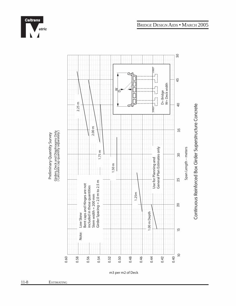
0.60
0.42
0.44
0.46
0.48
0.50
0.52
0.54
0.56
0.40
m3 per m2 of Deck
2.00
m
1.75
m
1.50
m
1.25
m
1.00
m D
epth
No
te:
Low
Ske
wB
ent
cap
s an
d H
ing
es a
re n
ot
incl
ud
ed in
th
ese
qu
anti
ties
Stem
wid
th =
200
mm
Gir
der
Sp
acin
g =
2.0
m to
2.5
m
DW
D=
Bri
dg
eW
= D
eck
wid
th
Use
for P
lan
nin
g a
nd
Gen
eral
Pla
n E
stim
ates
on
ly
0.58
2.
25 m
45
50
10
1520
2530
3540
Span
Len
gth
– m
eter
s
Cont
inuo
us R
einf
orce
d Bo
x G
irder
Sup
erst
ruct
ure
Conc
rete
11-8 ESTIMATING

BRIDGE DESIGN AIDS • MARCH 2005
0.85
0.80
No
te:
0.75
Use
for L
ow
Ske
w S
tru
ctu
res,
d
/s =
0.0
35-0
.045
0.
70
0.65
0.60
Si
mp
le S
pan
0.55
Use
for P
lan
nin
g a
nd
Gen
eral
Pla
n E
stim
ates
on
ly
Co
nti
nu
ou
s
0.50
0.45
0.40
m3 per m2 of Deck
10
1520
2530
3540
4550
55
6065
7075
80
Span
Len
gth
– m
eter
s
CIP
/ PS
Box
Gird
er S
uper
stru
ctur
e Co
ncre
te
ESTIMATING 11-9

BRIDGE DESIGN AIDS • MARCH 2005
140
150
160
170
180
190
200
130
Kgs of Bar Reinforcing /m3 of Concrete
No
te:
S
tem
wid
th =
355
mm
G
ird
er s
pac
ing
= 2
.0 to
2.5
m
1.00
m D
epth
1.25
m D
epth
1.50
m D
epth
1.75
m D
epth
2.00
m D
epth
Use
for P
lan
nin
g a
nd
Gen
eral
Pla
n E
stim
ates
on
ly
D/S
= 0
.067
D/S
= 0
.080
D/S
= 0.0
71D
/S=
0.07
4
10
12.5
15
17
.5
20
22.5
25
27
.5
30
32.5
35
Span
Len
gth
– m
eter
s
Tee
Beam
Sup
erst
ruct
ure
Bar R
einf
orci
ng
Prel
imin
ary
Qu
anti
ty S
urv
ey
Gir
der
s, D
eck
and
Dia
ph
rag
ms
On
ly
( Cal
cula
te c
ap q
uan
tity
sep
arat
ely
)
11-10 ESTIMATING

BRIDGE DESIGN AIDS • MARCH 2005
190
200
210
220
230
240
180
Kgs of Bar Reinforcing /m3 of Concrete
1.00
m D
epth
1.25
m D
epth
1.
50 m
Dep
th
1.75
m D
epth
2.00
m D
epth
Use
for P
lann
ing
and
Gen
eral
Pla
n Es
timat
es o
nly
Not
e:
Ste
m w
idth
= 3
55 m
m
Gird
er s
paci
ng =
2.0
to 2
.5 m
D/S
= 0
.059
D/S
= 0
.050
D/S
= 0
.053
D/S
= 0
.055
D/S
= 0
.057
42.5
15
17.5
20
22
.5
25
27.5
30
32
.5
35
37.5
40
Span
Len
gth
– m
eter
s
Co
nve
nti
on
ally
Rei
nfo
rced
Box
Gir
der
Su
per
stru
ctu
re B
ar R
ein
forc
ing
ESTIMATING 11-11
Prel
imin
ary
Qu
anti
ty S
urv
ey

BRIDGE DESIGN AIDS • MARCH 2005
Prel
imin
ary
Qu
anti
ty S
urv
ey
140
No
te:
A
pp
ly to
No
rmal
an
d L
ow s
kew
str
uct
ure
130
Bar
rier
Rai
ling
qu
anti
ties
no
t in
clu
ded
120
D/S
= 0
.035
- 0.
045
110
100
Use
for P
lan
nin
g a
nd
Gen
eral
Pla
n E
stim
ates
on
ly
90
Kgs Of Bar Reinforcing /m3 Of Concrete
20
30
40
50
60
7080
90
100
Span
Len
gth
– m
eter
s
CIP
/ P
S Bo
x G
ird
er S
up
erst
ruct
ure
Bar
Rei
nfo
rcin
g
11-12 ESTIMATING

BRIDGE DESIGN AIDS • MARCH 2005
Pres
tres
sin
g S
teel
- K
ilog
ram
s p
er s
qu
are
met
er (d
eck
area
)
40
CIP Prestressed Box Girder Prestressing Steel
35
30
25
20
15
10
5
0
0 10 20
Span Length – meters
30 40 50 60 70 80 90
f'c =
42MPa
d/s = 0.035
d/s = 0.040
d/s = 0.050
f'c = 28MPa f'c =
35MPa
L
Simple Span Box Girder
d/s= .035 to .050
f 's = 1860 MPa
Note: Use for planning and general plan estimates only.
ESTIMATING 11-13

BRIDGE DESIGN AIDS • MARCH 2005
CIP Prestressed Box Girder Prestressing Steel
Pres
tres
sin
g S
teel
- K
ilog
ram
s p
er s
qu
are
met
er (d
eck
area
)
0
5
10
15
20
25
30
35
40
d/s = 0.035
d/s = 0.040
d/s = 0.050
f'c = 28MPa
45
50
L L'
2 Span Box Girder w/ equal spans
d/s= .030 to .050 u= 0.15 f 's= 1860 MPa
d/s = 0.030
f'c =35MPa
f'c =42MPa
d/s = 0.045
Note: Use for planning and general plan estimates only.
0 20 40 60 80 100 120
Span Length – meters
11-14 ESTIMATING

BRIDGE DESIGN AIDS • MARCH 2005
CIP Prestressed Box Girder Prestressing Steel
Pres
tres
sin
g S
teel
- K
ilog
ram
s p
er s
qu
are
met
er (d
eck
area
)
0
5
10
15
20
25
30
35
40
d/s = 0.035
d/s = 0.040
d/s = 0.050
45
d/s = 0.030
f'c =35MPa
f'c =42MPa
3 /4 L 3 /4 LL
3 Span Box Girder w/ 3 /4 L end spans
d/s= .030 to .050 u= 0.15 f 's =1860 MPa
Note: Use for planning and general plan estimates only.
0 20 40 60 80 100 120
Span Length – meters
ESTIMATING 11-15

BRIDGE DESIGN AIDS • MARCH 2005
CIP Prestressed Box Girder Prestressing Steel
40
45
50
L L
3 Span Box Girder w/ equal spans
d/s= .030 to .050 u= 0.15 f ' s =1860 MPa
L
ea)
35
(dec
k ar
f'c = 42MPa
30
re m
eter
f'c = 35MPa
25
per
sq
ua
20
ilog
ram
s
d/s = 0.030 f'c = 28MPa
15
Ste
el -
K
d/s = 0.035
Pres
tres
sin
g
10 d/s = 0.040
d/s = 0.050
0
5
0
d/s = 0.045
20
Note: Use for planning and general plan estimates only.
Span Length – meters
40 60 80 100 120
11-16 ESTIMATING

BRIDGE DESIGN AIDS • MARCH 2005
CIP Prestressed Box Girder Prestressing Steel
50
40
45
3/4 L L
4 Span Box Girder w/ 3 /4 L end spans d/s= .030 to .050
u= 0.15 f's =1860 MPa
L 3/4 L
rea)
35
(dec
k a
f'c = 35MPa
30
re m
eter
f'c = 28MPa
25
per
sq
ua
20
ilog
ram
s
d/s =
0.0
30
15
Ste
el -
KPr
estr
essi
ng
10 d/s = 0.035
d/s = 0.040
0
5
d/s = 0.045
0 20
d/s = 0.050
Note: Use for planning and general plan estimates only.
Span Length – meters
40 60 80 100 120
ESTIMATING 11-17

BRIDGE DESIGN AIDS • MARCH 2005
CIP Prestressed Box Girder Prestressing Steel
40
45
50
L
4 Span Box Girder w/ equal spans
d/s= .030 to .050 u= 0.15 f's =1860 MPa
L L L
ea)
35
(dec
k ar
30
re m
eter f'c = 35MPa
25
per
sq
ua
20
ilog
ram
s
d/s =
0.0
30
f'c = 28MPa
15
d/s = 0.035
Ste
el -
KPr
estr
essi
ng
10 d/s = 0.040
d/s = 0.050
5 d/s = 0.045
Note: Use for planning and general plan estimates only.
0
0 20
Span Length – meters
40 60 80 100 120
11-18 ESTIMATING

BRIDGE DESIGN AIDS • MARCH 2005
Kilo
gra
ms
of S
tru
ctu
ral S
teel
per
Sq
uar
e Fo
ot
(Dec
k A
rea)
Simple Span Composite Welded Steel Girder
300
275
250
225
200
175
150
125
100
75
50
Loading: HS 20-44 + 35 psf allowance for future wearing surface.
Working stress design Structural steel: f = 252 MPa Reinf Steel: fs = 140 MPa Concrete: fc = 9 MPa
Use for Planning and
General Plan Estimate only
2.3 M Girder spacing
Optimum D/S ratio
.07
.07
.06.06
.05
.05
W
D= Total Depth
D/S = 0.05 to 0.07 Girder Spacing = 2.3M to 3.2M
Wts. of diaphragms, stiffeners, shear connectors and wind bracing approximated. Add 15% if Steel Bent Caps are used.
Note:
3.2 M Girder spacing
10 15 20 25 30 35 40 45 50
S = Span Length in Meters
ESTIMATING 11-19

BRIDGE DESIGN AIDS • MARCH 2005
Concrete Slab Thickness
Slab Reinforcement Lbs./C.Y. Concrete
6"
300
220
Deck P Thickness
L
Thru Type
Deck Type
Note: Quantities are for all structural steel including bearings but excluding deck plates. Use for all deck types (steel, wood or concrete)
fs = 20,000 psi Loading (Deck Type) E-50 thru E-72
Use for Planning and
General Plan Estimates only.
1/2"
3/8"
Deck PGird
ers - p
er track
LL
E60 - 1 tr
ack
E72 - 1 tr
ack
Thru Girders
E60
- 2 tr
acks
E72
- 2 tr
acks
D olled beams-per treck reck rolled beams - per trackD ack
12
10
8
6
4
2
0 25 50 75 100 125 150 175
Span Length – Feet
Railroad Bridge Superstructure (Structural Steel)
Stru
ctu
ral S
teel
In 1
00,0
00 lb
s. (T
ota
l)
11-20 ESTIMATING

BRIDGE DESIGN AIDS • MARCH 2005
Marginal Estimates The Marginal Estimate differs from the Advanced Planning and General Plan Estimates in that it is based on quantity calculations prepared from checked design plans. This marginal estimate is done at P&Q stage. Marginal Estimates for bridge items are segregated as follows:
Superstructure Substructure Other Elements
Concrete Concrete Bridge Removal Items Bar Reinforcing Bar Reinforcing Retaining Wall Items Structural Steel Excavation Slope Paving Joint Seals/Assemblies Backfill Approach Slab Items Deck Seals Seal Course Drill and Bond Dowel Prestressing Steel Piling Misc. Metal (Restrainer) Architectural Treatment Railings and Barriers Closure Wall Architectural Treatment Drill and Bond Dowel PC Girders/Slabs PTFE Bearings Asphalt Concrete Deck Drainage Systems Drill and Bond Dowel
A Marginal Estimate Form should be filled out for each structure, retaining wall, or sound wall with separate bridge number. Whenever there are identical parallel structures or where more than one structure is shown on a General Plan, only one Marginal Estimate Form should be filled out.
Quantity Take-Off Procedures First, determine the limits of each concrete type and the division between superstructure and substructure.
Divide the work into logical units such as footings, columns, etc. Be liberal with descriptions which will identify each unit. Use sketches where necessary for clarity.
If there is doubt whether or not to list an item, list it with a brief explanation. The Specifications Engineer will decide how it should be handled.
Two persons, or groups, will be assigned to independantly calculate quantities for the same structure. They should collaborate to the extent of setting up the same division of units for each
ESTIMATING 11-21

BRIDGE DESIGN AIDS • MARCH 2005
item. When calculations are complete, the two shall compare results and make necessary corrections according to the following percent error allowance:
Barrier, piles, precast units, or any item paid as EACH ............. Zero % (Exact)
Concrete, bar reinforcing steel, and structural steel quantities ....................... 3%
All others ........................................................................................................ 5%
The close review of the plans required in the process of quantity take-off frequently results in the discovery of errors or omissions. These must be brought to the designer's attention.
Bar Reinforcing Steel Example
Use form DS-D-0110, “Reinforcing Steel Quantities,” for tabulating reinforcing steel.
Note: For bar reinforcing steel, each individual bar size subtotal must be within 3% agreement between estimator and checker’s quantity calculations.
STATE OF CALIFORNIA • DEPARTMENT OF TRANSPORTATION
REINFORCING STEEL QUANTITIES DS-D-00110 (REV. 5/93) Page ______ of ______
PROJECT BRIDGE NAME DATE
ITEM SIZE NO. LENGTH TOTAL LENGTH - EACH SIZE
#13 #16 #19 #22 #25 #29 #32 #36 #43 #57
A 100 1.77 177
B 2 45.0 90
C 100 0.79 7.9
Tot. lengths
Weight per meter 0.994 1.552 2.235 3.042 3.973 5.06 6.404 7.907 11.38 20.24
Tot. weight per size
11-22 ESTIMATING

BRIDGE DESIGN AIDS • MARCH 2005
For the more complicated structures or portions of structures, it is suggested that the estimator and checker code (by number or letter) the reinforcing bars on the estimating prints prior to quantity take-off. This will facilitate final checking of quantities and reduce the possibility of omissions. An example is as follows:
Girder reinf
Slab reinf Slab reinf
#13 @ 460mm
#13 @ 460mm
#16 cont tot 2
C
B
A
Lump Sum Items Backup quantities are to be submitted for items paid for as “Lump Sum.” Quantities for the item “Bridge Removal” should be calculated either in cubic meters or square meter of bridge deck area. Other Lump Sum items should include a breakdown of quantity of all work involved in the item.
Fully Compensated Items A fully compensated item, or fully compensated labor and materials, indicates that payment is included in another item of work, and will be defined in the pay clause for that particular item. Fully compensated work is agreed upon by the Specification Engineer and the Structures Estimator, and does not preclude the quantitites for the fully compensated work from being provided in the quantity calculations.
Example:
The item Minor Concrete (Minor Structure) might include payment for Structure Excavation, Structure Backfill, and Drill and Bond Dowel. In which case, the quantities for each item should be calculated and provided on the Marginal Estimate, as to facilitate the sum of all costs into one “fully compensated” unit price.
ESTIMATING 11-23

BRIDGE DESIGN AIDS • MARCH 2005
Structure Type Coding The following coding is to be entered in the “Type” block on the Marginal Estimate summary forms. (See Appendix)
The first character in the field identifies the major material used or the construction method:
C – Concrete S – Steel T – Timber M – Masonry P – P/S, P/C I – P/S, CIP
The second and third characters describe the physical configuration of the main span:
BG – Box Girder IG – “I” girder SL – Slab IU – Inverted U SS – Seal Slab UG – “U” girder DU – Deck Units WG – Welded girder TG – “T” girder RB – Rolled beam DT – Double T TD – Truss deck IT – Inverted T TC – Truss Cantilever BU – Bulb T TB – Truss Bascule BW – Bin wall TL – Truss lift PA – Pipe, arch SU – Suspension P1 – Single pipe AR – Arch P2 – Double pipe LS – Log stringer B1 – Single box The second and third characters (continued)
T1 – Type 1 wall B2 – Double box T2 – Type 2 wall B3 – Triple box T3 – Type 3 wall B4 – Quadruple box T4 – Type 4 wall B5 – Quintuple box T5 – Type 5 wall XX – None of the above
11-24 ESTIMATING

BRIDGE DESIGN AIDS • MARCH 2005
The fourth character indicates the function of the structure: A – Undercrossing M – Equestrian undercrossing B – Overcrossing N – Cattle pass undercrossing C – Separation O – Culvert undercrossing D – Underpass P – Pedestrian bridge E – Overhead Q – Pedestrian overcrossing F – Bridge R – Equestrian overcrossing G – Bridge and Overhead S – Pipeline overcrossing H – Viaduct T – Pump house I – Sidehill Viaduct U – Culvert J – Double deck viaduct W – Retaining wall K – Tunnel X – Sound wall L – Pedestrian undercrossing Z – None of the above
The fifth character identifies the nature of construction:
N – New Q – Earthquake Retrofit W – Widening R – Raising Bridge E – Extension U – Rail Replacement (Upgrade Rail) M – Modification F – Repair/Rehab
ESTIMATING 11-25

BRIDGE DESIGN AIDS • MARCH 2005
Concrete Type Limits and Division betweenSuperstructure and Substructure
Cantilever Retaining wall type wingwall type wingwall
Bottom of girder
Wingwalls and Diaphragm Type Abutments
Cantilever Abutment
Strutted Abutment
Rigid Frame Abutment
Bent or Pier Bin Type Abutment Seat Type Abutment
Notes: 1. For retaining walls that are not classified as
wingwalls see sheet_ _. Bent Caps, Top Slabs, and Diaphragms for Precast Girder Bridges are paid as Structural Concrete, Bridge.
2. For pile extensions see sheets_ _.
Superstructure
Substructure
Structural Concrete, Bridge
Structural Concrete, Bridge Footing
11-26 ESTIMATING

BRIDGE DESIGN AIDS • MARCH 2005
Quantity Calculations and Summary Sheets Quantity calculations are to be clearly legible and easy to follow, including sketches and location references. They should be titled properly, identifying the estimator and the checker, the structure name and bridge number, and the date the calculations were performed.
Calculated quantities are to be summarized on Official State forms. The following is a list of forms available.
Form Number Form Name
DS-D-0015 Pile Summary
DS-D-0016 Bridge General Plan Estimate or Planning Estimate
DS-D-0017 Miscellaneous General Plan Estimate or Planning Estimate
DS-D-0019 Structural Quantity and Marginal Estimate
DS-D-0019A Marginal Estimate - Miscellaneous Structure Other Than Bridge
DS-D-0019B Marginal Estimate - Miscellaneous Structure Other Than Bridge (EQ Retrofit)
DS-D-0019SUP Marginal Estimate - Miscellaneous Structure Other Than Bridge
DS-D-0022 Summary - Structure Excavation and Structure Backfill
DS-D-0050 Concrete Summary
DS-D-0067 Bar Reinforcing Summary
DS-D-0100 Pile Quantity Calculations
DS-D-0110 Reinforcing Steel Quantities
DS-D-0153 Sound Wall Summary
DS-D-0154 Summary – Miscellaneous Metal – Bridge and Restrainer
DS-D-0000 Advance Planning Study & General Plan Estimate Checklist
Notes:
1. Obtain a current copy from the Cost Estimates website.
2. Do not fill out the “USE” column on the Marginal Estimate Sheet. This is for the cost estimator to determine. The cost estimator does any necessary rounding to the quantities per the Ready-to-List and Contract Award Guide (RTL Guide).
ESTIMATING 11-27

BRIDGE DESIGN AIDS • MARCH 2005
Quantity Summaries Transmitted to Resident Engineer’s Pending File, After Bid Acceptance The following forms are available for summarizing certain items for each structure, which are used in making progress pay estimates. Therefore, the breakdown should be subtotals as they would be constructed, and are submitted with the Marginal Estimate to the Cost Estimates Branch, who will forward them to the R.E. Pending File.
• SUMMARY-STRUCTURE EXCAVATION AND STRUCTURE BACKFILL
DS - D0022
• PILE SUMMARY
DS - D0015
• CONCRETE SUMMARY
DS - D0050
• BAR REINFORCING SUMMARY
DS - D0067
• SUMMARY - MISCELLANEOUS METAL - BRIDGE AND RESTRAINER
DS - D0154
11-28 ESTIMATING

BRIDGE DESIGN AIDS • MARCH 2005
Type 5 Retaining Wall Quantities
TYPE 5 RETAINING WALL - QUANTITIES ON SPREAD FOOTING
DESIGN H CRETE CON (m3/m)
REBAR (kg/m)
1200 1.02 40
1800 1.31 50
2400 1.77 74
3000 2.31 100
3600 3.37 127
TYPE 5 RETAINING WALL - QUANTITIES ON PILE FOOTING
DESIGN H CONCRETE
(m3/m) REBAR (kg/m)
1200 1.17 63
1800 1.35 73
2400 1.84 103
3000 2.41 126
3600 3.41 151
Note: Use for Advanced Plan and General Plan studies only.
ESTIMATING 11-29

BRIDGE DESIGN AIDS • MARCH 2005
Type 1 Retaining Wall Quantities
CONCRETE AND REBAR QUANTITIES PER LENGTH OF WALL FOR TYPE 1 RETAINING WALL ON 400 kN FOOTING
HDESIGN (m)
CONCRETE (m3/m)
REBAR (kg/m)
1.2 0.96 61
1.8 1.32 74
2.4 1.69 86
3.0 2.08 132
3.6 2.49 166
4.2 3.01 212
4.8 3.44 257
5.5 3.97 329
6.1 4.45 404
6.7 5.15 527
7.3 6.19 598
7.9 7.57 731
8.5 8.73 890
9.1 10.56 984
9.7 12.94 1109
10.3 14.52 1181
10.9 16.19 1374
Note: Use for Advanced Plan and General Plan studies only.
11-30 ESTIMATING

BRIDGE DESIGN AIDS • MARCH 2005
CONCRETE AND REBAR QUANTITIES PER LENGTH OF WALL FOR TYPE 1 RETAINING WALL ON SPREAD FOOTING
HDESIGN (m)
CONCRETE (m3/m)
REBAR (kg/m)
1.2 0.96 39
1.8 1.30 51
2.4 1.65 61
3.0 2.02 79
3.6 2.50 113
4.2 3.00 157
4.8 3.43 201
5.5 3.92 281
6.1 4.38 355
6.7 5.05 477
7.3 6.07 558
7.9 7.42 690
8.5 8.56 848
9.1 10.35 940
9.7 12.70 1062
10.3 14.26 1132
10.9 15.91 1326
Note: Use for Advanced Plan and General Plan studies only.
ESTIMATING 11-31

BRIDGE DESIGN AIDS • MARCH 2005
WINGWALL FOR DIAPHRAGM ABUTMENT
4.5
4
3.5
3
2.5
2
1.5
1
0.5
s = 3
.7m
s = 4
.3m
s = 4.9m
s = 5.5m
s = 6.1m
0.00 1.00 2.00 3.00 4.00 5.00
CL Abut.“S”
"Y" [
M]
1m
“Y”
M ³ OF CONCRETE
WINGWALL FOR DIAPHRAGM ABUTMENT (REBAR)
3.6
3.4
s =
3.7
m
s =
4.3
m
s =
4.9
m
s =
5.5
m
s =
6.1m
#16
@ 2
25
#19
@ 2
25
#22
@ 2
25
#25@
225
#29
@ 2
25
“S”
“Y”
CL Abut.
"Y" [
M]
3.2
1m3
2.8
2.6
2.4
0.00 100.00 200.00 300.00 400.00 500.00 600.00
Kg of Reinforcement
Note: See Standard Plan B0-1
11-32 ESTIMATING

BRIDGE DESIGN AIDS • MARCH 2005
Prec
ast P
rest
ress
ed C
oncr
ete
Slab
Qua
ntiti
es
915
mm
Wid
thTy
pica
lSe
ctio
ns
Gird
erLe
ngth
mm
Pf Kn
No.
13m
mSt
rand
s
Mas
s 13
Stra
ndKg
Mas
s of
Bar R
einf
Kg
Vol o
f Co
ncm
3
1220
mm
Wid
thTy
pica
l Se
ctio
ns
Gird
erLe
ngth
mm
Pf Kn
No.
13m
mSt
rand
s
Mas
s 13
Stra
ndKg
Mas
s of
Bar R
einf
Kg
Vol o
f Co
ncm
3
.91m
.3m
SI .9
1
6096
91
7 64
01
1006
33
5336
58
52.16
59.8
8 19
6.86
204.
57
1.60
1.68
SI 1.
22
1.22m
.3m
60
9664
01
1224
1339
42
6745
72
66.2
374
.84
265.
3627
5.34
2.
162.
27
SII .
91
7"
.91m
.38m
6706
65
9 70
10
721
7315
78
3 76
20
846
7925
91
2 82
30
975
8534
10
41
8839
11
13
9144
11
75
9449
12
50
9754
13
17
2438
2743
2743
3048
3353
3353
3658
3962
4267
4572
4572
41.7
348
.99
51.2
659
.42
67.5
970
.31
79.3
889
.36
99.3
411
0.22
113.
40
185.
5219
0.97
196.
4120
1.85
207.
3021
2.74
218.
1822
3.62
229.
0723
4.51
239.
95
1.90
1.98
2.06
2.16
2.24
2.32
2.41
2.49
2.58
2.67
2.75
SII 1
.22
7" 1.2
2m
.38m
6706
7010
7315
7620
7925
8230
8534
8839
9144
9449
9754
863
935
1032
1117
1202
1286
1375
1464
1553
1647
1740
3048
3353
3658
3658
3962
4267
4572
4877
5182
5486
6096
52.16
59.8
868
.04
71.2
279
.83
89.3
699
.34
109.
7712
0.66
132.
0015
1.50
249.
4825
6.74
264.
0027
1.71
278.
9628
6.22
293.
4830
1.19
308.
4531
4.34
322.
96
2.52
2.64
2.75
2.87
2.98
3.10
3.21
3.33
3.44
3.55
3.66
SII .
91
9"
.91m
.46m
1005
8 10
10
1036
3 10
68
1066
8 11
21
1097
3 11
88
1127
8 12
50
1158
2 13
08
1188
7 13
84
1219
2 14
6412
497
1544
3353
3658
3658
3962
4267
4267
4572
4877
5182
86.18
96.6
299
.34
110.
6812
2.47
126.
1013
8.35
151.5
016
5.11
258.
1026
4.00
269.
4427
5.34
281.2
328
6.68
292.
5729
8.02
303.
91
3.20
3.30
3.39
3.49
3.59
3.69
3.78
3.88
3.98
SII 1
.22
9" 1.2
2m
.46m
1005
810
363
1066
810
973
1127
811
582
1188
712
192
1249
7
1335
1397
1473
1553
1633
1713
1811
1918
2020
4572
4877
4877
5182
5486
5791
6096
6401
6706
117.
0312
8.82
132.
4514
4.70
157.
4017
1.01
184.
6219
8.68
213.
19
347.
9135
5.62
363.
3337
1.04
378.
7638
6.47
394.
1840
1.89
409.
60
4.23
4.36
4.48
4.61
4.73
4.86
4.99
5.12
5.24
SIV
.91
12" .9
1m
.46m
1280
2 12
15
1310
6 12
82
1341
1 13
44
1371
6 14
15
1402
1 14
7714
326
1540
14
630
1606
3962
4267
4572
4877
4877
5182
5483
129.
2814
2.43
156.
0417
0.55
174.
1818
9.15
204.
57
319.
7932
5.68
332.
0433
7.93
343.
8334
9.73
355.
62
4.14
4.24
4.34
4.43
4.53
4.63
4.73
SIV
1.22
12"
9"
1.22m
.53m
1280
213
106
1341
113
716
1402
114
326
1463
0
1633
1718
1807
1896
1985
2069
2172
5486
5791
6096
6401
6706
7010
7315
178.
7219
3.23
208.
2022
3.62
239.
5025
5.83
272.
61
430.
9243
9.08
447.
2545
5.41
463.
1347
1.29
479.
46
5.70
5.83
5.97
6.10
6.24
6.38
6.51
ESTIMATING 11-33

BRIDGE DESIGN AIDS • MARCH 2005 Pr
ecas
t Pre
stre
ssed
Con
cret
e Sl
ab Q
uant
ities
(con
t.)
915
mm
Wid
thTy
pica
lSe
ctio
ns
Gird
erLe
ngth
mm
Pf Kn
No.
13m
mSt
rand
s
Mas
s 13
Stra
ndKg
Mas
s of
Bar R
einf
Kg
Vol o
f Co
ncm
3
1220
mm
Wid
thTy
pica
l Se
ctio
ns
Gird
erLe
ngth
mm
Pf Kn
No.
13m
mSt
rand
s
Mas
s 13
Stra
ndKg
Mas
s of
Bar R
einf
Kg
Vol o
f Co
ncm
3
Gird
er D
epth
2.44
m
D
D =
.46m
9144
9449
9754
1005
810
363
1066
810
973
1127
8
1291
1357
1428
1504
1575
1647
1638
1789
4267
4267
4267
4267
4877
4877
4877
5486
100.
2510
3.42
106.
6011
0.22
129.
7313
3.36
136.
9915
8.76
193.
2319
8.68
204.
1220
9.56
215.
0122
0.45
225.
8923
1.34
2.51
2.59
2.68
2.76
2.84
2.93
3.01
3.10
Gird
er D
epth
2.44
m
D
D =
.46m
9144
9449
9754
1005
810
363
1066
810
973
1127
8
1335
1415
1495
1571
1651
1727
1807
1882
4267
4267
4267
4877
4877
4877
5486
5486
99.7
910
3.42
106.
6012
5.65
129.
7313
3.36
154.
2215
8.76
196.
8620
2.31
207.
7521
3.19
218.
6422
4.08
229.
5223
4.96
2.85
2.94
3.04
3.13
3.23
3.33
3.43
3.52
D =
.61m
1066
810
973
1127
811
582
1188
712
192
1249
712
802
1310
613
411
1371
6
1117
1193
1268
1348
1424
1504
1580
1660
1736
1816
1891
3658
3658
3658
4267
4267
4267
4877
4877
5486
5486
5486
99.7
910
2.51
105.
6912
6.55
129.
7313
3.36
156.
0416
0.12
184.
1618
824
192.
78
238.
5924
4.49
250.
3925
6.28
262.
1826
8.08
273.
9727
9.87
285.
7729
1.66
297.
56
3.36
3.46
3.56
3.66
3.75
3.85
3.95
4.04
4.14
4.24
4.34
D =
.61m
1066
810
973
1127
811
582
1188
712
192
1249
712
802
1310
613
4.11
1371
6
1193
1273
1353
1415
1495
1580
1664
1749
1833
1918
2003
3658
3658
4267
4267
4267
4877
4877
5486
5486
5486
6096
100.
2510
2.97
123.
3812
6.55
130.
1815
2.41
156.
0418
0.08
184.
1618
8.70
214.
55
241.3
224
7.21
253.
1125
9.01
264.
9027
0.80
276.
7028
2.59
288.
4929
4.39
300.
28
3.95
4.06
4.17
4.29
4.40
4.52
4.63
4.75
4.86
4.98
5.09
D =
.81m
1341
113
716
1402
114
326
1463
014
935
1524
015
545
1585
016
154
1645
916
764
1706
917
374
1767
817
983
1828
818
593
1889
819
202
1313
1380
1566
1513
1580
1647
1713
1780
1847
1914
1980
2047
2114
2181
2247
2314
2381
2448
2514
2581
4267
4267
4267
4267
4877
4877
4877
5486
5486
5486
6096
60.9
660
9667
0667
0667
0673
1573
1573
1579
25
146.
5114
9.69
153.
3215
6.49
182.
8018
6.43
190.
5121
8.64
222.
7222
7.25
257.
1926
1.73
266.
7229
8.47
303.
9130
8.90
342.
9234
8.82
354.
2639
0.10
317.
5232
3.87
330.
2233
6.57
342.
9234
9.27
355.
6236
1.97
368.
3237
4.67
381.0
238
7.37
393.
7240
0.08
406.
4341
2.78
419.
1342
5.48
431.8
343
8.18
5.04
5.15
5.27
5.38
5.50
5.62
5.73
5.85
5.96
6.08
6.19
6.32
6.44
6.54
6.66
6.77
6.89
7.00
7.12
7.23
D =
.81m
1341
113
716
140.
2114
326
1463
014
9.35
1524
015
545
1585
016
154
1645
916
764
1706
917
374
1767
817
983
1828
818
593
1889
819
202
1375
1446
1517
1589
1660
1731
1802
1873
1945
2016
2087
2158
2229
2301
2372
2443
2514
2585
2657
2728
4267
4267
4877
4877
4877
5486
5486
5486
6096
6096
6096
6706
6706
6706
7315
7315
7315
7925
7925
7925
146.
9715
0.14
166.
9217
9.17
182.
8021
0.02
214.
5521
8.64
247.
6725
2.66
257.
1928
8.04
293.
4829
8.47
331.5
833
7.02
342.
9237
7.85
383.
7539
0.10
320.
2432
6.59
332.
9433
9.29
345.
6435
1.99
358.
3436
4.69
371.0
437
7.40
383.
7539
0.10
396.
4540
2.80
409.
1541
5.50
421.8
542
8.20
434.
5544
0.90
5.87
6.01
6.15
6.29
6.42
6.55
6.69
6.82
6.96
7.09
7.23
7.36
7.50
7.62
7.77
7.89
8.04
8.16
8.30
8.43
11-34 ESTIMATING

BRIDGE DESIGN AIDS • MARCH 2005
Sources of Quantities for Standard Details SP = Standard Plans BDD = Bridge Design Details BDA = Bridge Design Aids
Concrete and Reinforcing: Retaining Wall. Type 1 SP B3-1 and B3-2
Cantilever Abutments BDD Section 6
Strutted Abutments BDD Section 20
Cantilever Wingwalls BDD Section 20
Standard Slab Bridges BDA Section 4
Steel: Reinforcing Bar Weights BDA 11-37
Piling Patterns – Retaining Walls BDD Section 6
Piling Patterns – Cantilever Abutment BDD Section 6
Railroad Track, Ballast, etc. BDD Section 12
Commonly Used Quantities and Factors Access Door to Cellular Abutment 0.6M × varies,, Standard Plan B0-13
Area Drain, Standard Plan B7, 5.5 kg
Asphalt Concrete 2,385 kg per M³
Batter Factors:
1:3 = 1.0541 1:5 = 1.0198
1:4 = 1.0308 1:6 = 1.0138
Deck Drain Type C, 141 kg., Frame and Grate only
Deck Drain Type D-1, 66 kg.
Deck Drain Type D-2, 56 kg.
Deck Drain Type D-3, 59 kg.
ESTIMATING 11-35

BRIDGE DESIGN AIDS • MARCH 2005
Deck Drain Type A, 8 kg., Grate only
Drain Pipe, 150 mm (3.4mm), 12.77 kg/M.
Epoxy Adhesive Bond Coat, 2L. per 1 M²
Equalizing Bolt @ Hinge – 20 kg., Miscellaneous Metal (Bridge) (1.2 M Hinge Width)
Galvanizing, add 3% to mass of metal
Hinge Assembly, Standard Slab 0.3 M Depth, 280 kg. per M
Ladder Rung, 3 kg. each (For MHs, catch basins, etc.)
Manhole Frame and Cover-Deck (Detail B7-11) 200 kg.
Manhole Frame and Cover Sidewalk (Detail B7-11) 110 kg.
Prestressing Steel – See Item Description
Reinforcing Steel Weights – See Appendix
Rock Base Material, RR Ballast, 1,940 kg. per M³
Slurry Leveling Course, 1 L. per 2.5 M²
Steel: 7,792 kg per M³
Aluminum: 2,730 Kg/M3
Earthquake Restrainers – Commonly Used Masses for Miscellaneous Metal
Swage fitting w/stud, nut, and jam nut 2.8 KG each
PL 250 mm × 250 mm. 26 KG each
Cable Drum – Type C-1 17.7 KG each
25 mm. Nut 0.14 KG each
19 mm. Galvanized Strand 1.54 KG/M (1.49 Ungalvanized)
32 mm in. H.S. Rod 6.48 KG/M
25 mm. Stud 4.00 KG/M
PL 25 mm × 125 mm. 25.09 KG/M
Galvanizing and welds Add 3%
11-36 ESTIMATING

BRIDGE DESIGN AIDS • MARCH 2005
Reinforcing Bar Data - Grade 420 (ACI 318-89)
Physical Properties Hook Dimensions
Bar Size
Weight (kg/m)
Nominal Diameter
(mm)
Area (mm2)
Standard Stirrups and Ties
"D" 90O 180O
"D" 90O 135O
"A" "J" "A" "A" "A"
10 0.560 9.5 71 60 150 80 125 40 105 105
13 0.994 12.7 129 80 200 105 150 50 115 115
16 1.552 15.9 199 95 250 130 175 65 155 140
19 2.235 19.1 284 115 300 155 200 115 305 205
22 3.042 22.2 387 135 375 180 250 135 355 230
25 3.973 25.4 510 155 425 205 275 155 410 270
29 5.060 28.7 645 240 475 300 375 - - -
32 6.404 32.3 819 275 550 335 425 - - -
36 7.907 35.8 1006 305 600 375 475 - - -
43 11.38 43.0 1452 465 775 550 675 - - -
57 20.24 57.3 2581 610 1050 725 925 - - -
"D"
Estimate "A"
90 Standard /90 Stirrup and Tie
"D""J"
Estimate
"A"
"D"
Estimate "A"
180 Standard 135 Tie Hook
ESTIMATING 11-37

BRIDGE DESIGN AIDS • MARCH 2005
This page has been left blank intentionally
11-38 ESTIMATING

BRIDGE DESIGN AIDS • MARCH 2005
Item Descriptions and Limits and Methods of Payment
Listed by Section
Bar Reinforcing Steel .................................................................................................... 11-44 Bar Reinforcing Steel (Epoxy Coated) .............................................................................. 11-45 Bar Reinforcing Steel (Retaining Wall) ............................................................................. 11-46 Headed Bar Reinforcement ............................................................................................... 11-46
Concrete .......................................................................................................................... 11-46 Seal Course Concrete ........................................................................................................ 11-46 Structural Concrete, Approach Slab (Type N) .................................................................. 11-47 Structural Concrete, Approach Slab (Type EQ) ................................................................ 11-47 Structural Concrete, Approach Slab (Type R) ................................................................... 11-47 Structural Concrete, Bridge ................................................................................................ 11-48 Structural Concrete, Bridge Footing ................................................................................... 11-48 Minor Concrete .................................................................................................................. 11-48 Structural Concrete, Lightweight ........................................................................................ 11-48 Structural Concrete, Pier Column ...................................................................................... 11-48 Structural Concrete, Retaining Wall (Not Bridge Wingwall) ............................................. 11-49 Slope Paving ....................................................................................................................... 11-49
Deck Rehabilitation Items ............................................................................................ 11-49
Earthquake Restrainers, Retrofit and Repair ........................................................... 11-50 Drill and Bond Dowel ......................................................................................................... 11-51 Drill and Bond Dowel (Epoxy Cartridges) ......................................................................... 11-51 Hinge Hold Down (Temporary) ......................................................................................... 11-51 Temporary Support (Existing Superstructure) ................................................................... 11-52
Earthwork ........................................................................................................................ 11-52 Structure Backfill or Structure Backfill (Bridge) ............................................................... 11-52 Structure Backfill (Retaining Wall) .................................................................................... 11-52 Structure Excavation or Structure Excavation (Bridge) .................................................... 11-52 Structure Excavation (Type A) .......................................................................................... 11-53 Structure Excavation (Type D) .......................................................................................... 11-53 Structure Excavation (Retaining Wall) ............................................................................... 11-53 Structure Excavation (Pier Column) .................................................................................. 11-54 Pervious or Permeable Backfill Material ........................................................................... 11-54 Excavation and Backfill in Waterways .............................................................................. 11-55
ESTIMATING 11-39

BRIDGE DESIGN AIDS • MARCH 2005
Joint Seals ........................................................................................................................ 11-56 Joint Seal (All Types) ......................................................................................................... 11-56 Joint Seal (Movement Rating 50 mm or Less) ................................................................... 11-56 Joint Seal Assembly (Movement Rating More than 50 mm) ............................................. 11-56
Metal ................................................................................................................................ 11-56 Miscellaneous Metal (Bridge) ............................................................................................ 11-56
Piling (Excluding CISS) ................................................................................................. 11-57 Furnish Piling ...................................................................................................................... 11-57 Drive Piles .......................................................................................................................... 11-57 Cast-in-Drilled-Hole (CIDH) Concrete Piling ................................................................... 11-57 Permanent Steel Casing ..................................................................................................... 11-57 Cast-in-Drilled-Hole Concrete Piling (Rock Socket) ......................................................... 11-58
Cast-in-Steel-Shell (CISS) Concrete Piling ............................................................... 11-58 Furnish Cast-in-Steel-Shell Concrete Piling ....................................................................... 11-58 Drive Cast-in-Steel-Shell Concrete Pile ............................................................................. 11-59
Non-Standard Piling ....................................................................................................... 11-59 Micropiles ........................................................................................................................... 11-59
Piling Illustrations .......................................................................................................... 11-60 Pile Extensions and Columns for Driven Piles ................................................................... 11-60 Pile Extensions and Columns for CIDH Concrete Piles .................................................... 11-61 CIDH Concrete Piling witn Permanent Steel Casing (or Shell) ........................................ 11-62 CIDH Concrete Piling with Permanent Steel Casing into Rock........................................ 11-63 CISS Concrete Piling .......................................................................................................... 11-64
Pipes, Conduits, Drains ................................................................................................. 11-65 Bridge Deck Drainage System........................................................................................... 11-65 Miscellaneous Pipes ........................................................................................................... 11-65 Sprinkler Control Conduit and Communications Conduit ................................................... 11-65 Supply Line Bridge ............................................................................................................. 11-65
Precast Girders ............................................................................................................... 11-66 Furnish Precast Concrete Girders ...................................................................................... 11-66 Erect Precast Concrete Girder ........................................................................................... 11-66
Prestressing Steel .......................................................................................................... 11-66 Prestressing Cast-in-Place Concrete ................................................................................. 11-66
11-40 ESTIMATING

BRIDGE DESIGN AIDS • MARCH 2005
Railings and Barriers ..................................................................................................... 11-67 Concrete Barriers ............................................................................................................... 11-67 Metal Railings ..................................................................................................................... 11-67 Temporary Railing .............................................................................................................. 11-67
Structural Steel ............................................................................................................... 11-67 Furnish and Erect Structural Steel (Bridge) ....................................................................... 11-67 Clean and Paint (Structural Steel, Steel Piling, Sign Structure, etc...) ............................... 11-68
Walls ................................................................................................................................. 11-68 Closure Walls ..................................................................................................................... 11-68 Mechanically Stabilized Earth Walls – MSE. .................................................................... 11-68 Sound Walls ........................................................................................................................ 11-69
Miscellaneous ................................................................................................................. 11-70 Architectural Treatment ..................................................................................................... 11-70 Asphalt Concrete ................................................................................................................ 11-70 Asphalt Membrane Waterproofing ..................................................................................... 11-70 Bridge Removal and Bridge Removal (Portion) ................................................................ 11-70 Column Casing – Steel ....................................................................................................... 11-71 Core Concrete .................................................................................................................... 11-71 Deck Seal ........................................................................................................................... 11-71 PTFE Bearings ................................................................................................................... 11-71 Remove Concrete .............................................................................................................. 11-71 Rock Slope Protection ........................................................................................................ 11-72 Soil Nail ............................................................................................................................... 11-72 Tieback Anchors ................................................................................................................ 11-72 Timber ................................................................................................................................ 11-72
ESTIMATING 11-41

BRIDGE DESIGN AIDS • MARCH 2005
Alphabetical Listing of Items Architectural Treatment ..................................................................................................... 11-70 Asphalt Concrete ................................................................................................................ 11-70 Asphalt Membrane Waterproofing ..................................................................................... 11-70 Bar Reinforcing Steel (Epoxy Coated) .............................................................................. 11-45 Bar Reinforcing Steel (Retaining Wall) ............................................................................. 11-46 Bridge Deck Drainage System........................................................................................... 11-65 Bridge Removal and Bridge Removal (Portion) ................................................................ 11-70 Cast-in-Drilled Hole (CIDH) Concrete Piling .................................................................... 11-57 Cast-in-Drilled Hole (CIDH) Concrete Piling (Rock Socket) ........................................... 11-58 CIDH Concrete Piling with Permanent Steel Casing into Rock........................................ 11-63 CIDH Concrete Piling with Permanent Steel Casing (or Shell) ........................................ 11-62 CISS Concrete Piling .......................................................................................................... 11-64 Clean and Paint (Structure Steel, Steel Piling, Sign Structure, etc...) ................................ 11-68 Closure Walls ..................................................................................................................... 11-68 Column Casing-Steel .......................................................................................................... 11-71 Concrete Barriers ............................................................................................................... 11-67 Core Concrete .................................................................................................................... 11-71 Deck Rehabiliatation Items ................................................................................................ 11-49 Deck Seal ........................................................................................................................... 11-71 Drill and Bond Dowel ......................................................................................................... 11-51 Drill and Bond Dowel (Epoxy Cartridges) ......................................................................... 11-51 Drive Cast-in-Steel-Shell Concrete Pile ............................................................................. 11-59 Drive Piles .......................................................................................................................... 11-57 Earthquake Restrainers, Retrofit and Repair ..................................................................... 11-50 Erect Precast Concrete Girder ........................................................................................... 11-66 Excavation and Backfill in Waterways .............................................................................. 11-55 Furnish and Erect Structural Steel (Bridge) ....................................................................... 11-67 Furnish Cast-in-Steel-Shell Concrete Piling ....................................................................... 11-58 Furnish Piling ...................................................................................................................... 11-57 Furnish Precast Concrete Girders ...................................................................................... 11-66 Headed Bar Reinforcing .................................................................................................... 11-46 Hinge Hold Down (Temporary) ......................................................................................... 11-51 Joint Seal (All Types) ......................................................................................................... 11-56 Joint Seal (Movement Rating 50mm or Less) .................................................................... 11-56 Joint Seal Assembly (Movement Rating More Than 50mm) ............................................. 11-56 Mechanically Stabilized Earth Walls-MSE......................................................................... 11-68 Metal Railings ..................................................................................................................... 11-67 Micropiles ........................................................................................................................... 11-59 Minor Concrete .................................................................................................................. 11-48
11-42 ESTIMATING

BRIDGE DESIGN AIDS • MARCH 2005
Miscellaneous Metal (Bridge) ............................................................................................ 11-56 Miscellaneous Pipes ........................................................................................................... 11-65 Permanent Steel Casing ..................................................................................................... 11-57 Pervious or Permeable Backfill Material ........................................................................... 11-54 Pile Extensions and Columns for CIDH Concrete Piles .................................................... 11-61 Pile Extensions and Columns for Driven Piles ................................................................... 11-60 Prestressing Cast-in-Place Concrete ................................................................................. 11-66 PTFE Bearings ................................................................................................................... 11-71 Remove Concrete .............................................................................................................. 11-71 Rock Slope Protection ........................................................................................................ 11-72 Seal Course Concrete ........................................................................................................ 11-46 Slope Paving ....................................................................................................................... 11-49 Soil Nail ............................................................................................................................... 11-72 Sound Walls ........................................................................................................................ 11-69 Sprinkler Control Conduit and Communication Conduit ..................................................... 11-65 Structural Concrete, Approach Slab (Type EQ) ................................................................ 11-47 Structural Concrete, Approach Slab (Type N) .................................................................. 11-47 Structural Concrete, Approach Slab (Type R) ................................................................... 11-47 Structural Concrete, Bridge ................................................................................................ 11-48 Structural Concrete, Bridge Footing ................................................................................... 11-48 Structural Concrete, Lightweight ........................................................................................ 11-48 Structural Concrete, Pier Column ...................................................................................... 11-48 Structural Concrete, Retaining Wall (Not Bridge Wingwall) ............................................. 11-49 Structure Backfill (Retaining Wall) .................................................................................... 11-52 Structure Backfill or Structure Backfill (Bridge) ............................................................... 11-52 Structure Excavation (Pier Column) .................................................................................. 11-54 Structure Excavation (Retaining Wall) ............................................................................... 11-53 Structure Excavation (Type A) .......................................................................................... 11-53 Structure Excavation (Type D) .......................................................................................... 11-53 Structure Excavation or Structure Excavation (Bridge) .................................................... 11-52 Supply Line Bridge ............................................................................................................. 11-65 Temporary Railing .............................................................................................................. 11-67 Temporary Support (Existing Superstructure) ................................................................... 11-52 Tieback Anchors ................................................................................................................ 11-72 Timber ................................................................................................................................ 11-72
ESTIMATING 11-43

BRIDGE DESIGN AIDS • MARCH 2005
Description of Contract Items
Bar Reinforcing Steel
• Quantity caluculated in kilograms.
• Two sets of quanity calculations should agree within 3% for each bar size.
Include:
1. Splices shown on the plans either graphically or in tabular form. See Appendix for lengths. Where lapped bars are of two sizes, use splice length based on the smaller bar.
2. An additional 2% for lap splices not shown on plans, as shown at bottom of Bar Reinforcing Summary Sheet.
3. Bond and anchorage lengths, see Bridge Design Details, Section 13, or consult designer.
4. Bar hooks, use “standard” unless dimensioned otherwise.
5. Dowels, grouted or bonded in drilled holes, except those for concrete barrier railings, and diaphragm bolsters.
6. Reinforcement for Cast-In-Place Concrete piling 600 mm and larger.
7. Reinforcement in anchorages for CIP prestress girders.
8. Longitudinal reinforcement in stirrup hooks of precast girders, see Bridge Design Details, Section 14.
9. Reinforcement around utility openings. See Standard Plans.
10. Bar chairs shown on plans.
11. Longitudinal bars at edge of deck and under railings.
12. Stirrup reinforcement at abutments, see Bridge Design Details 6-24.
Note:
• When calculating final quantities for standard slab bridges, do not use the approximate tabular data in BDA Section 4.
11-44 ESTIMATING

BRIDGE DESIGN AIDS • MARCH 2005
Do not include reinforcement or Epoxy coated reinforcement in:
1. Precast members (girders, walls, piling, panels,etc.)
Reinforcing for precast girders is shown on the marginal (final) estimate for use in pricing for nonstandard girders only. For nonstandard girders use 75 kg per m3.
2. Cast-In-Place Concrete Piling less than 600 mm
3. Concrete barriers
4. Bridge approach slabs
5. Bridge slope paving
6. Diaphragm bolsters for hinge restrainers
7. Hairpins in steel pile anchorages
8. Closure walls
9. Sound walls – precast or masonry block
10. Deck access closure (usually for EQ restrainers)
11. Ripped texture (reinforcement used to create ripped texture)
12. Concrete crib walls
13. Cable anchorages for railings
14. Concrete panels for reinforced earth walls
15. Supply line cradles
16. Concrete classified as “Minor” (Gutters, etc.)
17. Soil Nails
18. Expansion dams
Bar Reinforcing Steel (Epoxy Coated) 1. Estimate in kilograms(Add 2% for splices not shown on the plans)
2. The Specifications Engineer must be advised of all locations where epoxy-coated bar reinforcing steel is used.
3. Tabulate the quantity of Bar Reinforcing Steel (Epoxy-Coated) separately, except for reinforcing in concrete barrier railings, pilings less than 600 mm and precast members.
4. Use bar masses the same as for uncoated bars. (No allowance is made for the mass of epoxy.)
5. If any portion of a bar requires epoxy-coating, the entire bar will be coated.
ESTIMATING 11-45

BRIDGE DESIGN AIDS • MARCH 2005
6. Decks and Approach Slabs: In Environmental Area III, and some other corrosive environments, the deck and approach slab reinforcing steel is to be epoxy-coated.
Decks 300 mm thick and less:
Epoxy-coat the entire deck reinforcing.
Decks greater than 300 mm thick:
Refer to Memo to Designers , Section 8.
In all cases, the reinforcing in abutment, bent and girder diaphragms is to be coated to the same depth as the adjacent deck.
Bar Reinforcing Steel (Retaining Wall) 1. Estimate in kilograms. Tabular values do not include reinforcement in haunch when concrete
barrier is attached at top; therefore, this must be added to the tabular values.
2. The specifications engineer must be advised of all locations where epoxy-coated bar reinforcing steel is used.
Headed Bar Reinforcement 1. Estimate in EACH units (each head).
Concrete
Seal Course Concrete 1. Estimate in cubic meters per limits shown on plans.
2. This item is for concrete placed under water and is designated on the plans as Seal Course Concrete.
3. See Bridge Design Details, Section 7.
11-46 ESTIMATING

BRIDGE DESIGN AIDS • MARCH 2005
Structural Concrete, Approach Slab (Type N) 1. Estimate in cubic meters.
2. Included in the item price per cubic meter is everything shown on the approach slab sheets, including structure approach drainage system, geocomposite drain, plastic pipe, drainage pads, treated permeable base, filter fabric, woven tape fabric, miscellaneous metal, pourable seals, epoxy-coated bar reinforcement and epoxy-coated miscellaneous bridge metal, transverse joint seals at sleeper slabs, water stops, and sliding joints.
Structural Concrete, Approach Slab (Type EQ) 1. Estimate in cubic meters.
2. Included in the item price per cubic meter is everything shown on the approach slab sheets, such as miscellaneous bridge metal, pourable seals, epoxy-coated bar reinforcement, and epoxy-coated miscellaneous bridge metal.
Structural Concrete, Approach Slab (Type R) 1. Estimate in cubic meters.
2. For use where new approach slabs are desired at exisitng bridges; replacing PCC slabs or AC paving.
3. Curing time for Type R approach slabs may require as little as 4 hours with use of chemical admixtures, depending on lane closure restrictions. Otherwise, 5 days is standard cure time.
4. Separate quantities for Aggregate Base (Approach Slab) will be required, and it is assumed to be 10% of the volume of the Structural Concrete, Approach Slab (Type R).
5. At PS&E, the designer should indicate in the “Memos to Specifications Engineer” whether mudjacking was used under the existing approach slabs. Check bridge maintenance records for this condition.
6. Included in the item price per cubic meter are removing and disposing of portions of the existing structure and pavement materials, furnishing and placing miscellaneous metal, epoxy-coated bar reinforcement, drilling and bonding of bar reinforcement or abutment tie rods, and Type AL joint seals.
ESTIMATING 11-47

BRIDGE DESIGN AIDS • MARCH 2005
Structural Concrete, Bridge 1. Compute in cubic meters from plan dimensions.
2. Do not deduct for volumes occupied by reinforcing steel, prestressing steel, miscellaneous metal, structural steel, piling, drain pipes or joint filler.
3. Deduct for utility openings.
4. Do not deduct for access openings in soffit.
5. Include bent caps, slab, and diaphragms for precast girder superstructures.
Structural Concrete, Bridge Footing 1. Compute in cubic meters from plan dimensions.
2. Includes all concrete designated on the plans as bridge footing concrete.
3. Do not deduct for volumes occupied by reinforcing steel or piling.
Minor Concrete 1. Estimate in cubic meters.
2. This pay item will include necessary earthwork and reinforcing steel.
Structural Concrete, Lightweight 1. Estimate in cubic meters to limits shown on the plans, and report separately on Marginal
Estimate and Concrete Summary form.
2. Do not deduct for volumes occupied by reinforcing steel.
Structural Concrete, Pier Column 1. Estimate in cubic meters to limits shown on the plans.
2. This item is for concrete placed in excavated (mined) shafts.
3. Do not deduct for volumes occupied by reinforcing steel.
11-48 ESTIMATING

BRIDGE DESIGN AIDS • MARCH 2005
Structural Concrete, Retaining Wall (Not Bridge Wingwall) 1. Estimate in cubic meters.
2. Retaining Walls that have a retaining wall number are not classified as wingwalls and are paid for as Structural Concrete, Retaining Wall.
3. Wingwalls for abutments, even though they consist of lengths of standard retaining walls, will normally be considered as Structural Concrete, Bridge, unless the wingwall is part of a retaining wall that has a retaining wall number assigned or the retaining wall is greater than 15 meters in length.
4. Do not deduct for volumes occupied by reinforcing steel.
Slope Paving 1. Estimate the cubic meters of concrete. This pay item will include necessary earthwork and
reinforcing steel.
2. Estimate permeable material in cubic meters.
3. Estimate drainage inlets by each.
4. Estimate drain pipes in linear meters for each size and type.
5. Do not deduct for volumes occupied by reinforcing steel.
Deck Rehabilitation Items
Remove Unsound Concrete CM Use M² from chain survey
Remove Deck Surfacing M² Assumed to be AC
Asphalt Concrete (Type B) TONNE M³ × 2.28 = TONNE
Epoxy Adhesive (Bond Coat) L 2L per 1 M² use with PCC patch and PCC exp. dam.
Portland Cement Concrete M³ Usually same quantity as (Patch) Remove Unsound Concrete
Expansion Dam M³ Includes reinf. and dowels
Deck Seal M² Lx(W + .5) includes primer
ESTIMATING 11-49

BRIDGE DESIGN AIDS • MARCH 2005
Slurry Leveling Course L 2.5 L per 1 M².Use on rough decks only
Joint Seal M Indicate MR
Rapid Setting Concrete(Patch) M³
Clean Bridge Deck M²
Furnish Bridge Deck Treatment L
Treat Bridge Deck M²
Asphalt Concrete (Type B) TONNE For shoulders
Remove Unsound Concrete M³
Scarify Concrete Surface M² Include approaches
Deck Overlay (Concrete) M³
Saw Concrete Joint M
Furnish Polyester Concrete Overlay M³
Place Polyester Concrete Overlay M²
Rapid Setting Concrete (Deck Overlay) M³
Prepare Concrete Bridge Deck Surface M²
Earthquake Restrainers, Retrofit, and Repair
Access Opening, Deck .......................................................................................................... EA This includes the concrete removal work.
Access Opening, Soffit (For existing structures only) .......................................................... EA This includes the concrete removal work and the closing steel plate pour assembly.
Minor Concrete (Minor Structure) ......................................................................................... M³ This item will cover a variety of abutment blocks, shear blocks, bent blocks, pedestal supports, etc. It includes concrete, bar reinforcing, drill and bond dowels and excavation and backfill if needed, if the total quantity is small.
Diaphragm Bolster ................................................................................................................ EA These are used to reinforce concrete girders. The item includes concrete, bar reinforcing, and drill and bond dowels.
11-50 ESTIMATING

BRIDGE DESIGN AIDS • MARCH 2005
Close Access, Deck .............................................................................................................. EA This includes concrete (any type), bar reinforcing and the temporary steel cover plate.
Core Concrete (each size) ...................................................................................................... M
Miscellaneous Metal (Restrainer) ......................................................................................... KG Include all metal involved in the restrainers. Provide separate estimates for cable type, pipe type, and rod type. Deduct for holes. Ignore small non-repetitive copes and cuts. Add 3% for galvanizing and welds.
Tiedown Anchor .................................................................................................................... EA Includes core concrete through footing.
Asphalt Membrane Waterproofing ......................................................................................... M²
Column Casing (Steel) ........................................................................................................... KG Includes casing, grout and seal, expanded polyethylene, welding, backup plates, drain extension, and cleaning and painting structural steel. Earthwork separate.
See “Column Casing - Steel” under “Miscellaneous” in this section for masses for Square meters.
Drill and Bond Dowel 1. Calculate length in the unit meters of drilled hole.
2. Reinforcement will be paid for as bar reinforcing steel.
Drill and Bond Dowel (Epoxy Cartridges) 1. Paid by the unit EACH.
2. Reinforcement will be paid as bar reinforcing steel.
3. Installation per manufacturers specifications . DO NOT indicate hole depth on plans.
Hinge Hold Down (Temporary) 1. Paid by the unit EACH.
2. Specify by type – prestressed or dead load.
ESTIMATING 11-51

BRIDGE DESIGN AIDS • MARCH 2005
Temporary Support (Existing Superstructure) 1. Paid by the unit EACH.
(Provide square meter of supported area.)
Earthwork
Structure Backfill or Structure Backfill (Bridge) 1. Paid by the unit cubic meters.
2. See Standard Plans for limits of payment.
3. Deduct volume of concrete within the excavation limits, except for crib walls.
4. Deduct pervious and/or permeable material, if any.
5. Compute quantity only at those locations where backfill must be compacted.
Compaction of backfill is not required in waterways or channel areas which are not beneath embankments, pavements, or slope protection.
6. Do not calculate quantity for structure excavation or backfill directly related to bridge removal.
Structure Backfill (Retaining Wall) 1. Paid by the unit cubic meters.
2. Use when Structural Concrete (Ret. Wall) is required.
3. See Standard Plans for limits of payment.
Structure Excavation or Structure Excavation (Bridge) 1. Paid by the unit cubic meters.
2. See Standard Plans for limits of payment.
3. When plans require concrete to be placed against undisturbed material, the quantity shall still be calculated with widths 300 mm outside the concrete dimensions.
4. Where bridge approach embankments are to be surcharged, the placing and removal of excess material will be paid as a separate district item.
11-52 ESTIMATING

BRIDGE DESIGN AIDS • MARCH 2005
5. The grading plane may be assumed to be 450 mm below finished pavement.
6. Where the volumes of Structure Excavation and Remove Concrete overlap:
Case 1. If there is no item of work (on the entire contract) for removing concrete and the amount is minor and lies within the limits of payment for structure excavation, it can be included and paid for as structure excavation. Inform Specifications Engineer.
Case 2. If there is an item for Remove Concrete, either by M³ or LS, deduct the volume
of concrete only from the structure excavation volume.
Case 3. If there is an item for Bridge Removal, deduct the volume of concrete and related excavation from the structure excavation volume.
If it would clarify the situation in either Case 2 or Case 3, draw a separate pay limit diagram on the plans.
Structure Excavation (Type A) 1. Paid by the unit cubic meters.
2. Use where excavation will be below water level.
3. Use only when seal course is shown.
Structure Excavation (Type D) 1. Paid by the unit cubic meters.
2. Use where ground water is anticipated, but a seal course is not shown.
3. Note or details should be shown on the plans.
Structure Excavation (Retaining Wall) 1. Paid by the unit cubic meters.
2. Use when Structural Concrete (Retaining Wall) is required.
3. See Standard Plans for limits.
ESTIMATING 11-53

BRIDGE DESIGN AIDS • MARCH 2005
Structure Excavation (Pier Column) 1. Paid by the unit cubic meters.
2. Use for excavated (Mined) shafts.
3. Use with Structural Concrete (Pier Column)
4. Calculate quantity to 150 mm outside concrete dimensions, see Bridge Design Details, Section 7-20.
Pervious or Permeable Backfill Material 1. Paid by the unit cubic meters.
2. See Standard Plans for limits.
11-54 ESTIMATING

BRIDGE DESIGN AIDS • MARCH 2005
Excavation and Backfill in Waterways
A
Roadway excavation
Grading plane
Structure excavation
300 mm
Stripping
A
600 mm min below girder
Specify desired slope
Structure Excavation (Bridge) if water is not a problem Structure Excavation (Type A) if a seal course is shown Structure Excavation (Type D) if ground water is anticipated, but a seal course is not shown
View A–A
Grading plane
Structure backfill
Do not compute a volume for Structure Backfill (Bridge) in a waterway unless the channel is paved or the area supports slope protection. Uncompacted backfill is included in the cost of excavation
300mm
Grading plane
Structure excavation Improved channel
Seal Course Concrete
Seal Course
300 mm
300 mm300 mm
300 mm300 mm
300mm
ESTIMATING 11-55

BRIDGE DESIGN AIDS • MARCH 2005
Joint Seals
Joint Seal (All Types) 1. Paid by the unit meters.
Joint Seal (Movement Rating 50 mm or Less) 1. Paid by the unit meters for each MR.
2. See Standard Plan B6-21 for pay limit extension at low side of the deck.
Joint Seal Assembly (Movement Rating More than 50 mm) 1. Paid by the unit meters for each MR.
2. See Bridge Standard Detail Sheet XS-12-59, for pay limit extension at the low side of the deck.
Metal
Miscellaneous Metal (Bridge) 1. Paid by the unit kilograms, add 3% if galvanized.
2. The Standard Specifications (75-1.03) lists the items to be paid as Miscellaneous Metal (Bridge).
3. Miscellaneous metal in connection with prestressing, such as anchorages, saddles, ducts, etc., are not paid as miscellaneous metal (Bridge). These are included in payment for Prestressing CIP Concrete.
4. Estimate the mass of manhole frame and covers when they are to be paid for by the State. Sometimes they are furnished to the contractor by the utility company.
5. Bridge Deck Drainage System paid separately.
6. Do not calculate mass for access opening plates. They are included in the cost of concrete for new construction and in the cost of Soffit Access Openings for existing structures.
11-56 ESTIMATING

BRIDGE DESIGN AIDS • MARCH 2005
Piling (Excluding CISS)
Furnish Piling 1. Paid by the unit meters from specified tip to cut-off elevation. Battered piles are measured
as the total length of pile along the pile centerline.
2. A separate pay item is required for each type or class of piling.
Drive Piles 1. Paid by the unit each, for each type or class of pile.
Cast-In-Drilled-Hole (CIDH) Concrete Piling 1. Paid by the unit meters from specified tip to cut-off elevation.
2. For piles less than 600 mm in diameter, the price of the pile includes all bar reinforcing steel, including reinforcement which extends into a footing, cap, or deck.
3. For piles 600 mm in diameter and larger, compute the weight of bar reinforcing steel and include with Bar Reinforcing Steel (Bridge). Add pile reinforcement, including reinforcement which extends into a footing, cap, or deck, and any spirals or hoops used to confine this pile reinforcement, to the "other" column on the Bar Reinforcing summary sheet.
4. Use only the standard size diameters as shown in Attachment 3 of Memo to Designers 3-1. For diameters less than 1.0 meter, the item name shall include the diameter in millimeters. For diameters greater than or equal to 1.0 meter, the item name shall include the diameter in meters. This does not apply to CIDH concrete piles with permanent steel casings.
Permanent Steel Casing 1. Paid by the unit meter from cut-off elevation to specified tip of the permanent steel casing.
If there is any geotechnical capacity required along the length of the steel, it is not a “casing”. This item covers furnishing and installing the permanent steel casing; no separate “drive” item is necessary. For the rare case where a CIDH concrete pile requires geotechnical capacity along the length of the steel casing, and a CISS concrete pile is not appropriate, the item “Driven Steel Shell” will be used and will be measured and paid for in the same manner as a permanent steel casing.
ESTIMATING 11-57

BRIDGE DESIGN AIDS • MARCH 2005
Cast-In-Drilled-Hole Concrete Piling (Rock Socket) 1. Paid in the unit meter from the specified tip of the rock socket to the specified tip of the
permanent steel casing (or to the specified tip of the larger diameter CIDH concrete pile if no casing is shown on the plans).
2. For piles less than 600 mm in diameter, the price of the pile includes all bar reinforcing steel, including reinforcement which extends above the rock socket.
3. For piles 600 mm in diameter and larger, compute the quantity of bar reinforcing steel and include it in the Bar Reinforcing Steel (Bridge) item. This pile reinforcement, including reinforcement which extends above the rock socket, and any spirals or hoops used to confine this pile reinforcement, should be added to the "other" column on the Bar Reinforcing summary sheet.
4. Use only the standard size diameters as shown in Attachment 3 of Memo to Designers 3-1.
Cast-In-Steel-Shell (CISS) Concrete Piling
Furnish Cast-In-Steel-Shell Concrete Piling 1. Paid by the unit meter from specified tip to cut-off elevation.
2. Use standard Nominal Pipe Size (NPS) sizes for pile diameters less than or equal to 1500 mm.
3. Use outside pile diameter in meters for pile diameters greater than 1500 mm.
4. For pile sizes less than 600 mm in diameter, the price of the pile includes all bar reinforcing steel, including reinforcement which extends into a footing, cap, or deck.
5. For pile sizes 600 mm in diameter and larger, compute the weight of bar reinforcing steel and include with Bar Reinforcing Steel (Bridge). This pile reinforcement, including reinforcement which extends into a footing, cap, or deck, and any spirals or hoops used to confine this pile reinforcement, should be added to the "other" column on the Bar Reinforcing summary sheet.
6. This item includes furnishing of both steel shell and concrete filling.
7. A separate item is required for each diameter of piling.
11-58 ESTIMATING

BRIDGE DESIGN AIDS • MARCH 2005
Drive Cast-In-Steel-Shell Concrete Pile 1. Estimate by each, for each diameter of piling.
2. Includes driving the shell, clean-out of the shell, and placement of the concrete filling.
Non-Standard Piling
Micropiles 1. Paid by the unit each.
2. Includes furnishing and installing the micropile (including casings, grout, reinforcement, and anchorages).
ESTIMATING 11-59

BRIDGE DESIGN AIDS • MARCH 2005
Pile Extensions and Columns for Driven Piles*
Case 1 Case 2 Case 3
Bar R
einf
orci
ng
Stee
l (Br
idg
e)
Stru
ctu
ral C
oncr
ete
(Bri
dg
e)Li
mit
s o
f pay
men
t fo
r fu
rnis
h p
ilin
g
Dri
ven
Con
cret
e Pi
ling
or fu
ll le
ngt
h C
ISS
Con
cret
e Pi
ling
Lim
its
of p
aym
ent f
or fu
rnis
h p
ilin
g
Lim
its
of p
aym
ent f
or fu
rnis
h p
ilin
g
Bar R
einf
orci
ng
Stee
l (Br
idg
e)
Stru
ctu
ral C
oncr
ete
(Bri
dg
e)
Driven Piling or CISS Concrete Piling
Steel Piling
cut-off elevation
CIP Column
cut-off elevation
cut-off elevation
cut-off elevation
cut-off elevation
Soffit (Typ) See note 4
CIP Column
Notes 1. The extension may or may not have the same reinforcing as the pile. 2. Pay limits shown here should also be included on the plans. 3. Calculate pile length to specified tip elevation. 4. Limits of embedment into soffit to be determined by the designer and shown on the plans. 5. CISS Pile Extensions may need to be cleaned and painted. * Includes CISS concrete piles
11-60 ESTIMATING

BRIDGE DESIGN AIDS • MARCH 2005
Pile Extensions and Columns for CIDH Concrete Piles
Case 1 Case 2
Lim
its
of p
aym
ent f
or C
IDH
co
ncr
ete
pili
ng
Bar
Rei
nfor
cin
g St
eel (
Brid
ge)
Stru
ctu
ral C
oncr
ete
(Bri
dg
e)
CIP Column
cut-off elevation
Soffit (Typ) See note 4
Lim
its
of p
aym
ent f
or C
IDH
co
ncr
ete
pili
ng
Bar
Rei
nfor
cin
g St
eel (
Brid
ge)
Stru
ctu
ral C
oncr
ete
(Bri
dg
e)
cut-off elevation
CIDH Concrete Piling (600 mm φ or larger)
CIDH Concrete Piling
Dissimilar CIP Concrete Column
Notes 1. The extension may or may not have the same reinforcing as the pile. 2. Pay limits shown here should also be included on the plans. 3. Estimate pile length from cut-off elevation to specified tip elevation. 4. Limits of embedment into soffit to be determined by the designer and shown on the plans.
ESTIMATING 11-61

BRIDGE DESIGN AIDS • MARCH 2005
CIDH Concrete Piling with Permanent Steel Casing (or Shell)
Pile cut-off elevation
X mm
SOIL W mm*
Lim
its
of p
aym
ent f
or X
mm
Per
man
ent S
teel
Cas
ing
Specified Tip Elevation for Permanent Steel Casing
Y mm**
Lim
its
of p
aym
ent f
or W
mm
Cas
t-In
-Dri
lled
-Ho
le C
on
cret
e Pi
ling
Pile specified tip elevation
* Thickness of casing must be shown on the plans. * For diameters 1500 mm or less, the diameter of the CIDH concrete piling will be called the same as the outside casing (W=X). For diameters greater than 1500 mm, the CIDH
concrete piling diameter controls and should be a standard size. * CIDH sizes must be a standard size.
11-62 ESTIMATING

BRIDGE DESIGN AIDS • MARCH 2005
CIDH Concrete Piling with Permanent Steel Casing into Rock
CIDH cut-off elevation
SOIL W mm*
X mm
See Note 1
ROCK
Lim
its
of p
aym
ent f
or W
mm
CID
H C
on
cret
e Pi
ling
an
d L
imit
sLi
mit
s o
f pay
men
t fo
r Y m
m C
IDH
of p
aym
ent f
or X
mm
Per
man
ent S
teel
Cas
ing
C
on
cret
e Pi
ling
(Ro
ck S
ock
et)
Y mm**
CIDH (rock socket) specified tip elevation
Notes 1. Specified Tip Elevation for Permanent Steel Casing and W mm CIDH concrete piling, and cut-off elevation for Y mm CIDH concrete piling (Rock Socket). * For diameters 1500 mm or less, the diameter of the CIDH concrete piling will be called the same as the outside diameter of the casing (W=X). For diameter greater than 1500 mm,
the CIDH concrete piling diameter is equal to the inside diameter of the casting. * CIDH Concrete Piling (Rock Socket) must be a standard diameter.
ESTIMATING 11-63

BRIDGE DESIGN AIDS • MARCH 2005
CISS Concrete Piling
cut-off elevation
Z mm*
SOIL
Lim
its
of p
aym
ent
for F
urn
ish
Z m
m C
ISS
Co
ncr
ete
Pilin
g
specified tip elevation
* Thickness and outside diameter should be shown in pile data table (see Memo to Designers 3-1).
11-64 ESTIMATING

BRIDGE DESIGN AIDS • MARCH 2005
Pipes, Conduits, Drains
Bridge Deck Drainage System 1. Paid by the unit kilogram.
2. Include inlets, pipes, supports, etc.
3. Add 3% to mass for galvanized portions.
Miscellaneous Pipes 1. Paid by the unit meter, for each size and type. Indicate thickness for steel pipes, and class for
pressure rating for asbestos and PVC pipes.
Sprinkler Control Conduit and Communication Conduit 1. Usually a District Item. Design may be asked to calculate length through structure for
transmittal to District.
2. See Standard Plan B14-3.
Supply Line Bridge 1. Estimate by meters for each size. Estimate to 1.5 meters beyond wingwall, see Standard Plan
B14-4. The payment per meter of pipe includes hangers, supports, brackets, and expansion details.
2. Do not calculate mass for Access Opening Plates for supply lines, as payment is included in the concrete item.
3. Plan Sheet from the Mechanical Design Branch must be included with Bridge Plans for sizes greater than 100 mm.
4. Estimate casing separately by meter. For limits see Standard Plans (B7-10).
ESTIMATING 11-65

BRmDGEADEsmGNA mDsA•AMARcHA2005
PrecastAGirders
Furnish Precast Concrete Girders
1. Paid by the unit EACH and separate by nominal lengths and types.
2. List conventionally reinforced and prestressed girders separately.
3. Indicate concrete, bar reinforcing steel, and prestressing quantities for each non-standard girder. Show this information at the bottom of the Marginal Estimate form.
4. For spliced post tensioned girders, calculate prestressing separately in kilograms of steel.
Erect Precast Concrete Girder
1. Paid by the unit EACH for each length.
PrestressingASteel
Prestressing Cast-in-Place Concrete
1. The contract item Prestressing Cast-in-Place Concrete includes placing ducts, prestressing steel, stressing, anchorages, and grouting.
2. Estimate prestressing steel in kilograms, do not include anchorages, ducts, etc. Paid by Lump Sum.
3. Estimate epoxy coated prestressing steel separately. Use strand masses the same for uncoated strands.
4. Mass
Pf× Length × 7,840 = kg1,074,000
P × Length × 7,840 Jack = kg1,396,000
Pf or Pjack in KN Length in meters
For RR loading add 7.5%
11-66 EsTIMATING

BRIDGE DESIGN AIDS • MARCH 2005
Railings and Barriers
Concrete Barriers 1. Calculate quantities of each type separately. Paid by meters. Payment includes the bar
reinforcing steel and all bar reinforcing that extends into the barrier. For Types such as 25B, 26A, 732B, 736B earthwork is included.
2. Drill and bond dowels for Type R rail replacement is included in the price per meter of barrier.
Metal Railing 1. These are usually steel railings such as tubular hand railing, chain link railing, or cable railing.
2. Calculate quantities for each type separately in meters. This includes anchor bolts or post pockets.
Temporary Railing 1. Estimate by meters for locations shown on the plans or required for falsework openings. Type
K should be in 6.1 meters increments.
2. The total length for payment includes the lengths each time it is used at (or moved to) a new location.
3. Include pay quantity for K-Rail in “Advanced Planning Estimates” only. District will include quantities with District Items at PS&E.
Structural Steel
Furnish Structural Steel (Bridge) and Erect Structural Steel (Bridge) 1. Segregate by type of steel and estimate in kilograms.
2. Include bearings (except PTFE Spherical Bearings), anchor bolts, shear connectors, and expansion dams (except where expansion dams are galvanized or embedded in concrete).
3. Ignore small, non-repetitive cuts, copes, and bolt holes.
4. Add 3% for welds and bolts.
ESTIMATING 11-67

BRIDGE DESIGN AIDS • MARCH 2005
Clean and Paint (Structural Steel, Steel Piling, Sign Structure, etc...) 1. Estimate by kilograms of steel sections to be painted.
2. Paid by Lump Sum.
Walls
Closure Walls 1. Estimate by square meter.
2. Specify alternative(s) if all three are not allowed.
3. Architectural treatment for closure wall is included in the cost per square meter of wall.
Mechanically Stabilized Earth Walls – MSE 1. Paid by the square meter.
2. Includes excavation, backfill, drainage, and architectural treatment.
11-68 ESTIMATING

BRIDGE DESIGN AIDS • MARCH 2005
Sound Walls ESTIMATING QUANTITIES
A. M² of wall, indicate each type.** A A
B. M³ of Minor Concrete ( Minor Structure), includes excavation, backfill & reinforcing
B* B* C. M of Concrete Barrier (indicate type).
SpreadTrench D. Usual retaining wall quantities.
E. M of CIDH concrete piling, indicate size.
1.2
m
max
A F. M of special wall cap if used. A
C C
B
Cont footing Over 1.2 m
Case 1 Case 2
If wall is both Case 1 and 2, use Case 2
Over 1.2 m
A
C
D
A
C
Retaining Wall Bridge
A
E*
A
C
E
A
C
B
E
A
B*
E*
Case 3 Case 4
If wall is both Case 3 and 4, use Case 4
Pile Cap
1.2 m max
A
C
B
E
* These are separate items ** Usual types
TYPICAL SOUND WALL ITEMS
. 400 mm CIDH concrete piling
. Sound wall (Masonry block)
. Minor concrete (Sound wall)
. Concrete barrier (TYPE)
If the sound wall is sitting on a retaining wall or concrete barrier, all the support items are typically paid for separately. If a sound wall is sitting on anything else, everything is included in the square meter price of the sound wall. However, all
quantities are needed for cost estimating.
ESTIMATING 11-69

BRIDGE DESIGN AIDS • MARCH 2005
Miscellaneous
Architectural Treatment 1. Estimate by square meter of area for each type to be treated.
2. Architectural treatment for Mechanically Stabilized Earth walls (MSE walls) and closure walls is included in square meter cost of wall.
Asphalt Concrete 1. Estimate by tonne. (2,250 kg per m³)
2. Use Type B for overlays on concrete bridge decks.
3. If the roadwork also has AC (Type B), contact the District Designer to see if they will include the quantity in their estimate. If so, note this on the Marginal Estimate Form.
Asphalt Membrane Waterproofing 1. Estimate by square meter for area delineated on plans.
2. This is for underground use, not for use as a deck seal.
Bridge Removal and Bridge Removal (Portion) 1. Usually paid as a lump sum.
2. Calculate square meter area of deck, and type of bridge, for complete bridge removal.
3. For Bridge Removal (Portion) calculate in cubic meters of concrete to be removed (except for concrete barriers).
4. Unless noted otherwise, removal will be to 0.91 meters below finished grade.
5. Includes excavation and backfill directly associated with removal.
6. Provide As-Built GP sheets for bridge removal.
7. If concrete barrier is to be removed, provide length to be removed.
11-70 ESTIMATING

BRIDGE DESIGN AIDS • MARCH 2005
Column Casing – Steel 1. Calculate quantities in kilograms.
2. Mass (kilograms) per square meter of various thicknesses
9.5 mm = 75.3 kg per m2 of column casing
12 mm = 100.1 kg per m2 of column casing
16 mm = 125.7 kg per m2 of column casing
19 mm = 148.3 kg per m2 of column casing
25 mm = 199.5 kg per m2 of column casing
Core Concrete 1. Calculate length of hole to be cored in meters for each diameter size core.
Deck Seal 1. Estimate by square meter. Use distance between rails plus 127 mm above finished surface
at each rail face. This is for a membrane seal.
2. See also Quantity Take Off for Deck Rehabilitation.
3. Also need item for clean deck, in square meters, on deck rehabilitation projects.
PTFE Bearings 1. Paid by the unit EACH, for concrete structures.
2. Paid by the unit kilograms of structural steel, for steel structures.
3. Multiple discs in a bearing assembly count as a single unit.
Remove Concrete 1. Estimate in cubic meters. Concrete will be removed to a depth of one meter below finished
grade unless shown otherwise.
2. See also Structure Excavation.
ESTIMATING 11-71

BRIDGE DESIGN AIDS • MARCH 2005
Rock Slope Protection 1. Usually a District item – check with District Project Engineer.
2. Estimate in cubic meters. Specify size of rock (1/4T, 1/2T, etc), and placement method.
3. Item includes necessary excavation, etc.
4. Does not include fabric required (separate items).
Soil Nails 1. Paid by length in the unit meter.
Tieback Anchors 1. Paid by the unit EACH.
Timber 1. Paid by cubic meter. Use nominal sizes and do not deduct for bevels or daps.
2. Do not estimate hardware such as nails, lag bolts, washers, etc.
3. Estimate structural metal, such as shapes, castings, eyebars, etc., by the kilogram and report separately.
4. Estimate treated and untreated separately.
5. Estimate timber catwalks by meters.
11-72 ESTIMATING

Cost Estimates Home
California Home
Caltrans > Division of Engineering Services > SDS & EE > Structure Office Engineer > Cost Estimates
Cost Estimates Branch
Services provided: - The ES Cost Estimates Branch provides project cost estimates and construction working day schedules for all phases of project development for highway bridges and transportation related structures. Additionally, the Branch collects, organizes, analyzes and disseminates statistical cost data for bridge construction work.
Documents & Spreadsheets:
Forms
Construction Statistics, 2003
Comparative Bridge Cost 2004 (English Units)
Comparative Bridge Cost 2004 (Metric Units)
Last updated 08-10-2004
Back to Top of Page
© 2004 State of California. Conditions of Use Privacy Policy
http://www.dot.ca.gov/hq/esc/estimates/ [4/7/2005 11:13:40 AM]