beams: deformation by superposition deflection by superposition
TRANSCRIPT
1
• A. J. Clark School of Engineering •Department of Civil and Environmental Engineering• A. J. Clark School of Engineering •Department of Civil and Environmental Engineering• A. J. Clark School of Engineering •Department of Civil and Environmental Engineering• A. J. Clark School of Engineering •Department of Civil and Environmental Engineering• A. J. Clark School of Engineering •Department of Civil and Environmental Engineering
Third EditionLECTURE
199.7 – 9.8
Chapter
BEAMS: DEFORMATION BY SUPERPOSITION
byDr. Ibrahim A. Assakkaf
SPRING 2003ENES 220 – Mechanics of Materials
Department of Civil and Environmental EngineeringUniversity of Maryland, College Park
LECTURE 19. BEAMS: DEFORMATION BY SUPERPOSITION (9.7 – 9.8) Slide No. 1ENES 220 ©Assakkaf
Deflection by Superposition
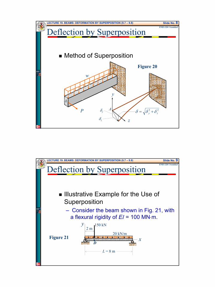
Method of Superposition– When a beam is subjected to several loads
(see Fig. 18) at various positions along the beam, the problem of determining the slope and the deflection usually becomes quite involved and tedious.
– This is true regardless of the method used.– However, many complex loading
conditions are merely combinations of
2
LECTURE 19. BEAMS: DEFORMATION BY SUPERPOSITION (9.7 – 9.8) Slide No. 2ENES 220 ©Assakkaf
Deflection by Superposition
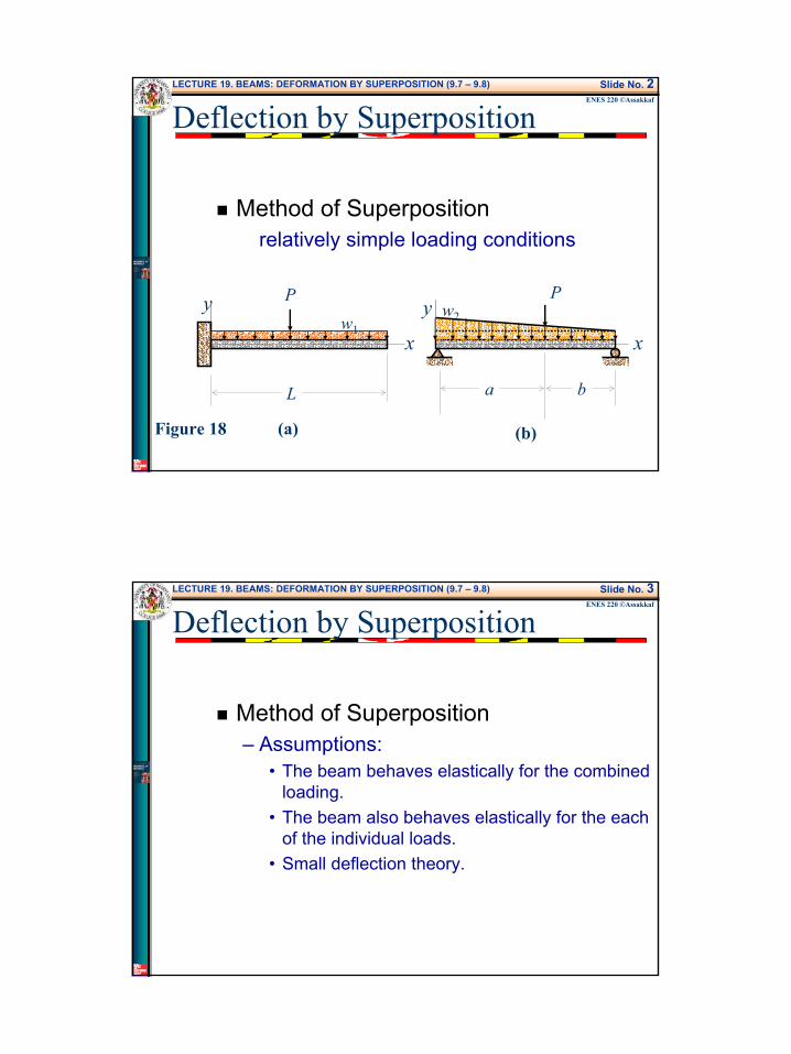
Method of Superpositionrelatively simple loading conditions
x
y
x
yP P
L a b
Figure 18 (a) (b)
w1w2
LECTURE 19. BEAMS: DEFORMATION BY SUPERPOSITION (9.7 – 9.8) Slide No. 3ENES 220 ©Assakkaf
Deflection by Superposition
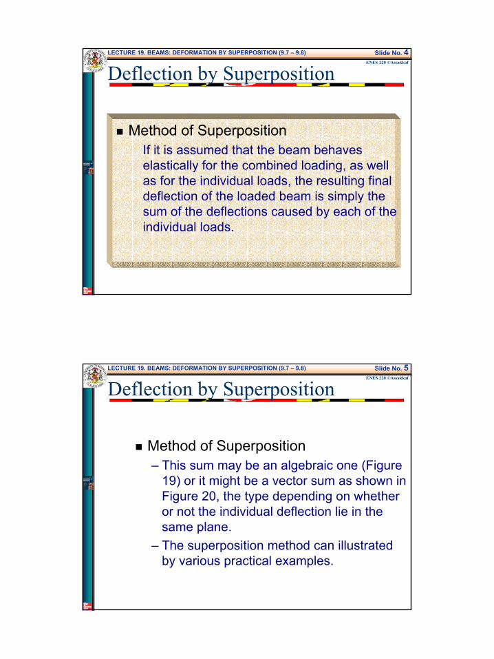
Method of Superposition– Assumptions:
• The beam behaves elastically for the combined loading.
• The beam also behaves elastically for the each of the individual loads.
• Small deflection theory.
3
LECTURE 19. BEAMS: DEFORMATION BY SUPERPOSITION (9.7 – 9.8) Slide No. 4ENES 220 ©Assakkaf
Deflection by Superposition
Method of SuperpositionIf it is assumed that the beam behaves elastically for the combined loading, as well as for the individual loads, the resulting final deflection of the loaded beam is simply the sum of the deflections caused by each of the individual loads.
LECTURE 19. BEAMS: DEFORMATION BY SUPERPOSITION (9.7 – 9.8) Slide No. 5ENES 220 ©Assakkaf
Deflection by Superposition
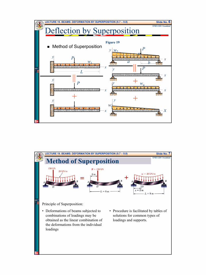
Method of Superposition– This sum may be an algebraic one (Figure
19) or it might be a vector sum as shown in Figure 20, the type depending on whether or not the individual deflection lie in the same plane.
– The superposition method can illustrated by various practical examples.
4
LECTURE 19. BEAMS: DEFORMATION BY SUPERPOSITION (9.7 – 9.8) Slide No. 6ENES 220 ©Assakkaf
Deflection by Superposition
Method of Superposition
x
y PP
L
w1
y
xa b
w2
x
y
x
y
x
x
xy
P
P
P
y
y
||
+
wu
wt
||+
+
Figure 19
LECTURE 19. BEAMS: DEFORMATION BY SUPERPOSITION (9.7 – 9.8) Slide No. 7ENES 220 ©Assakkaf
Method of Superposition
Principle of Superposition:
• Deformations of beams subjected to combinations of loadings may be obtained as the linear combination of the deformations from the individual loadings
• Procedure is facilitated by tables of solutions for common types of loadings and supports.
5
LECTURE 19. BEAMS: DEFORMATION BY SUPERPOSITION (9.7 – 9.8) Slide No. 8ENES 220 ©Assakkaf
Deflection by Superposition
Method of Superposition
w
P
y
z
A
Aδy
δz
22zy δδδ +=
Figure 20
LECTURE 19. BEAMS: DEFORMATION BY SUPERPOSITION (9.7 – 9.8) Slide No. 9ENES 220 ©Assakkaf
Deflection by Superposition
Illustrative Example for the Use of Superposition– Consider the beam shown in Fig. 21, with
a flexural rigidity of EI = 100 MN⋅m.
x
y 150 kN
20 kN/m
L = 8 m
2 m
Figure 21D•
6
LECTURE 19. BEAMS: DEFORMATION BY SUPERPOSITION (9.7 – 9.8) Slide No. 10ENES 220 ©Assakkaf
Deflection by Superposition
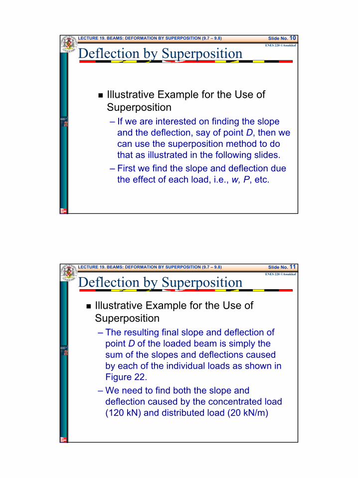
Illustrative Example for the Use of Superposition– If we are interested on finding the slope
and the deflection, say of point D, then we can use the superposition method to do that as illustrated in the following slides.
– First we find the slope and deflection due the effect of each load, i.e., w, P, etc.
LECTURE 19. BEAMS: DEFORMATION BY SUPERPOSITION (9.7 – 9.8) Slide No. 11ENES 220 ©Assakkaf
Deflection by SuperpositionIllustrative Example for the Use of Superposition– The resulting final slope and deflection of
point D of the loaded beam is simply the sum of the slopes and deflections caused by each of the individual loads as shown in Figure 22.
– We need to find both the slope and deflection caused by the concentrated load (120 kN) and distributed load (20 kN/m)
7
LECTURE 19. BEAMS: DEFORMATION BY SUPERPOSITION (9.7 – 9.8) Slide No. 12ENES 220 ©Assakkaf
Deflection by Superposition
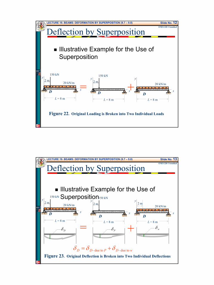
Illustrative Example for the Use of Superposition
x
y150 kN
20 kN/m
L = 8 m
2 m
x
y150 kN
L = 8 m
2 m
x
y
20 kN/m
L = 8 m
= +
Figure 22. Original Loading is Broken into Two Individual Loads
D D D
LECTURE 19. BEAMS: DEFORMATION BY SUPERPOSITION (9.7 – 9.8) Slide No. 13ENES 220 ©Assakkaf
Illustrative Example for the Use of Superposition
x
y150 kN
20 kN/m
L = 8 m
2 m
x
y150 kN
L = 8 m
2 m
x
y
20 kN/m
L = 8 m
= +
Figure 23. Original Deflection is Broken into Two Individual Deflections
D D D
2 m
Dδ Pδ wδ
wDPDD todue todue −− += δδδ
Deflection by Superposition
8
LECTURE 19. BEAMS: DEFORMATION BY SUPERPOSITION (9.7 – 9.8) Slide No. 14ENES 220 ©Assakkaf
Deflection by Superposition
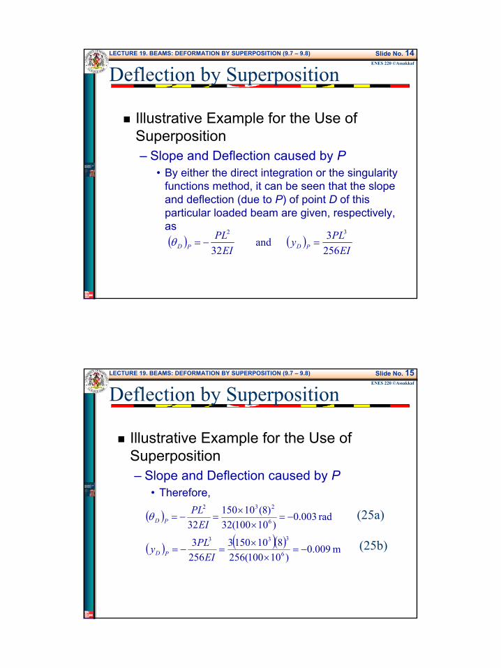
Illustrative Example for the Use of Superposition– Slope and Deflection caused by P
• By either the direct integration or the singularity functions method, it can be seen that the slope and deflection (due to P) of point D of this particular loaded beam are given, respectively, as( ) ( )
EIPLy
EIPL
PDPD 2563 and
32
32
=−=θ
LECTURE 19. BEAMS: DEFORMATION BY SUPERPOSITION (9.7 – 9.8) Slide No. 15ENES 220 ©Assakkaf
Deflection by Superposition
Illustrative Example for the Use of Superposition– Slope and Deflection caused by P
• Therefore,
( )
( ) ( )( ) m 009.0)10100(256
81015032563
rad 003.0)10100(32
)8(1015032
6
333
6
232
−=×
×=−=
−=×
×=−=
EIPLy
EIPL
PD
PDθ (25a)
(25b)
9
LECTURE 19. BEAMS: DEFORMATION BY SUPERPOSITION (9.7 – 9.8) Slide No. 16ENES 220 ©Assakkaf
Deflection by Superposition
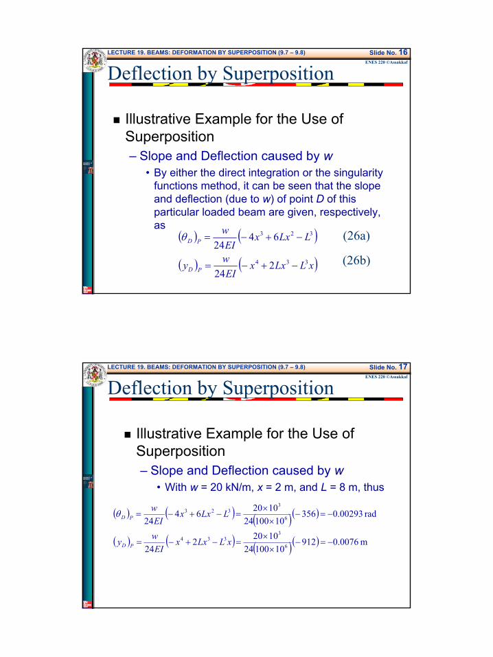
Illustrative Example for the Use of Superposition– Slope and Deflection caused by w
• By either the direct integration or the singularity functions method, it can be seen that the slope and deflection (due to w) of point D of this particular loaded beam are given, respectively, as
( ) ( )
( ) ( )xLLxxEI
wy
LLxxEI
w
PD
PD
334
323
224
6424
−+−=
−+−=θ (26a)
(26b)
LECTURE 19. BEAMS: DEFORMATION BY SUPERPOSITION (9.7 – 9.8) Slide No. 17ENES 220 ©Assakkaf
Deflection by Superposition
Illustrative Example for the Use of Superposition– Slope and Deflection caused by w
• With w = 20 kN/m, x = 2 m, and L = 8 m, thus
( ) ( ) ( )( )
( ) ( ) ( )( ) m 0076.09121010024
1020224
rad 00293.03561010024
10206424
6
3334
6
3323
−=−×
×=−+−=
−=−×
×=−+−=
xLLxxEI
wy
LLxxEI
w
PD
PDθ
10
LECTURE 19. BEAMS: DEFORMATION BY SUPERPOSITION (9.7 – 9.8) Slide No. 18ENES 220 ©Assakkaf
Deflection by Superposition
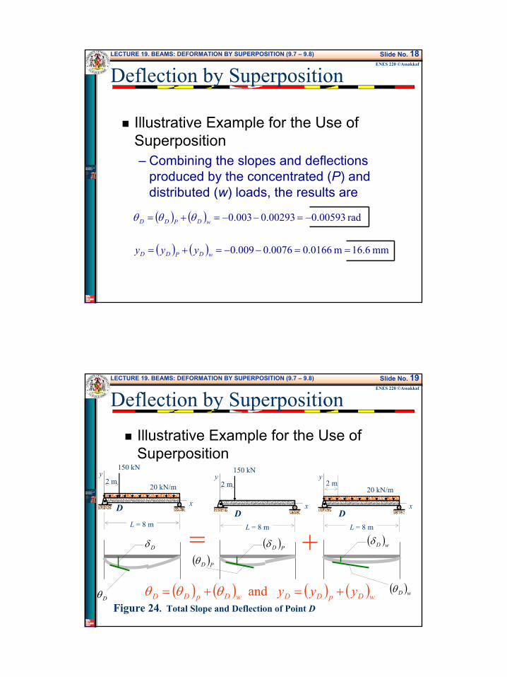
Illustrative Example for the Use of Superposition– Combining the slopes and deflections
produced by the concentrated (P) and distributed (w) loads, the results are
( ) ( )
( ) ( ) mm 6.16m 0166.00076.0009.0
rad 00593.000293.0003.0
==−−=+=
−=−−=+=
wDPDD
wDPDD
yyy
θθθ
LECTURE 19. BEAMS: DEFORMATION BY SUPERPOSITION (9.7 – 9.8) Slide No. 19ENES 220 ©Assakkaf
Illustrative Example for the Use of Superposition
x
y150 kN
20 kN/m
L = 8 m
2 m
x
y150 kN
L = 8 m
2 m
x
y
20 kN/m
L = 8 m
= +
Figure 24. Total Slope and Deflection of Point D
D D D
2 m
Dδ ( )PDδ ( )wDδ
( ) ( ) ( ) ( )wDpDDwDpDD yyy +=+= and θθθDθ
( )wDθ
( )PDθ
Deflection by Superposition
11
LECTURE 19. BEAMS: DEFORMATION BY SUPERPOSITION (9.7 – 9.8) Slide No. 20ENES 220 ©Assakkaf
Deflection by Superposition
General Procedure of Superposition– It is evident from the last results that the
slope or deflection of a beam is the sum of the slopes or deflections produced by the individual loads.
– Once the slopes or deflections produced by a few typical individual loads have been determined by one of the methods already
LECTURE 19. BEAMS: DEFORMATION BY SUPERPOSITION (9.7 – 9.8) Slide No. 21ENES 220 ©Assakkaf
Deflection by Superposition
General Procedure of Superposition– Presented, the superposition method
provides a means of quickly solving a wide range of more complicated problems by various combinations of known results.
– As more data become available, yet a wider range of problems can be solved by the method of superposition.
12
LECTURE 19. BEAMS: DEFORMATION BY SUPERPOSITION (9.7 – 9.8) Slide No. 22ENES 220 ©Assakkaf
Deflection by Superposition
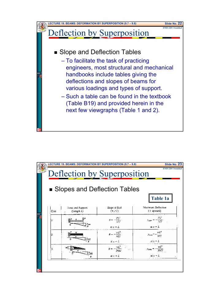
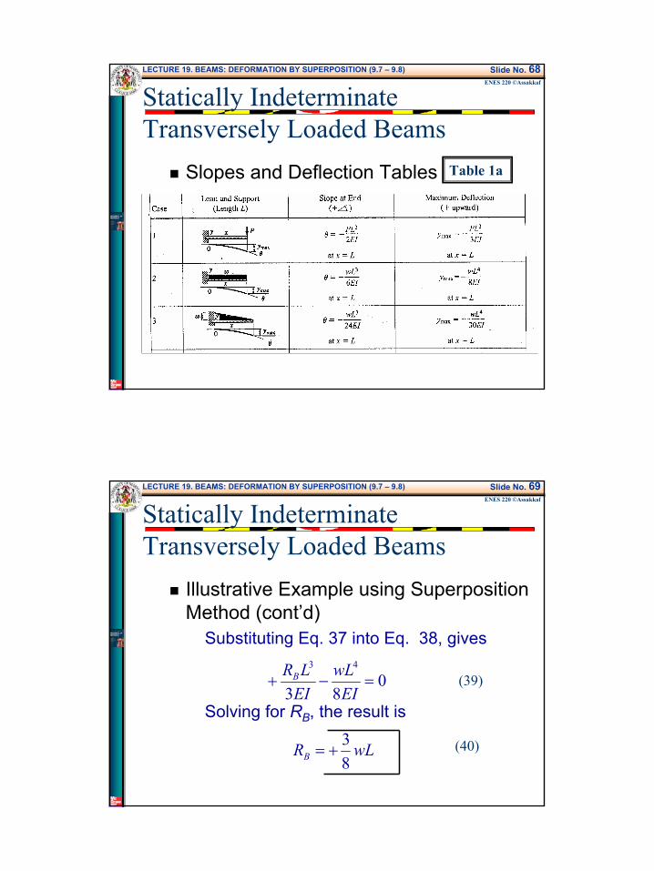
Slope and Deflection Tables– To facilitate the task of practicing
engineers, most structural and mechanical handbooks include tables giving the deflections and slopes of beams for various loadings and types of support.
– Such a table can be found in the textbook (Table B19) and provided herein in the next few viewgraphs (Table 1 and 2).
LECTURE 19. BEAMS: DEFORMATION BY SUPERPOSITION (9.7 – 9.8) Slide No. 23ENES 220 ©Assakkaf
Deflection by Superposition
Slopes and Deflection TablesTable 1a
13
LECTURE 19. BEAMS: DEFORMATION BY SUPERPOSITION (9.7 – 9.8) Slide No. 24ENES 220 ©Assakkaf
Deflection by Superposition
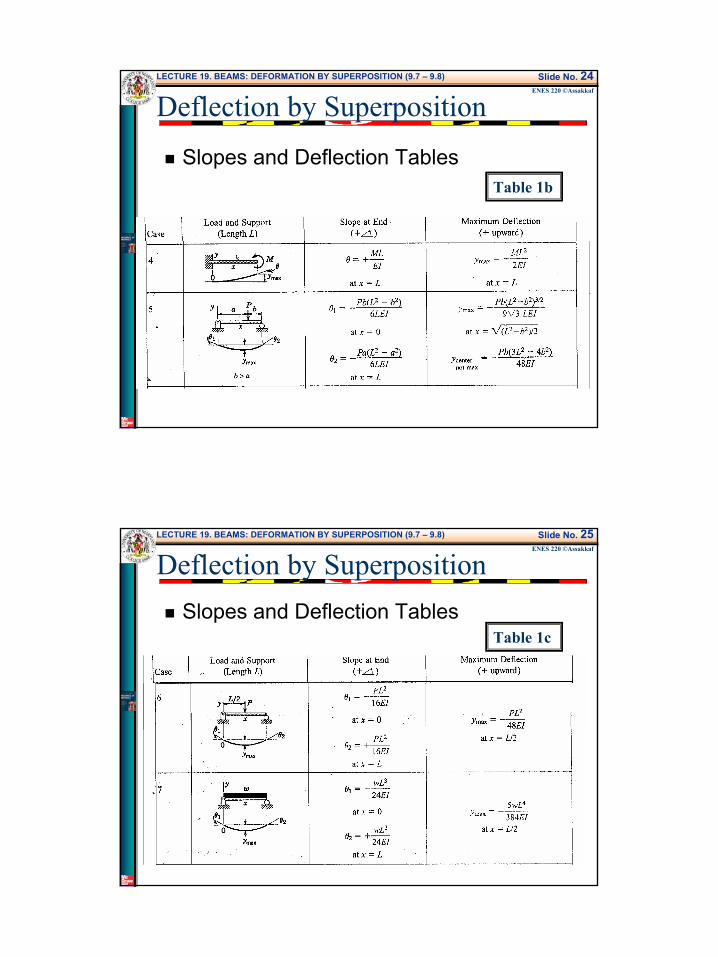
Slopes and Deflection TablesTable 1b
LECTURE 19. BEAMS: DEFORMATION BY SUPERPOSITION (9.7 – 9.8) Slide No. 25ENES 220 ©Assakkaf
Deflection by SuperpositionSlopes and Deflection Tables
Table 1c
14
LECTURE 19. BEAMS: DEFORMATION BY SUPERPOSITION (9.7 – 9.8) Slide No. 26ENES 220 ©Assakkaf
Deflection by Superposition
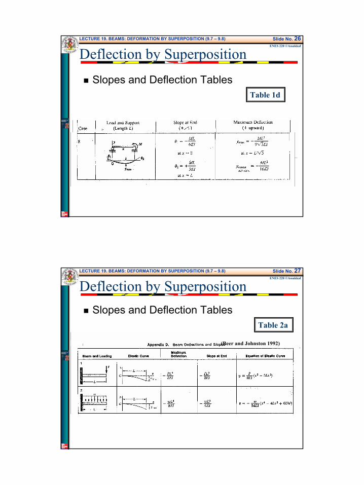
Slopes and Deflection TablesTable 1d
LECTURE 19. BEAMS: DEFORMATION BY SUPERPOSITION (9.7 – 9.8) Slide No. 27ENES 220 ©Assakkaf
Deflection by SuperpositionSlopes and Deflection Tables
Table 2a
(Beer and Johnston 1992)
15
LECTURE 19. BEAMS: DEFORMATION BY SUPERPOSITION (9.7 – 9.8) Slide No. 28ENES 220 ©Assakkaf
Deflection by Superposition
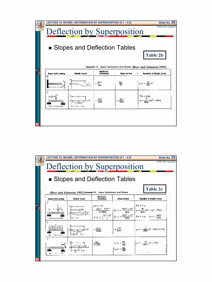
Slopes and Deflection TablesTable 2b
(Beer and Johnston 1992)
LECTURE 19. BEAMS: DEFORMATION BY SUPERPOSITION (9.7 – 9.8) Slide No. 29ENES 220 ©Assakkaf
Deflection by SuperpositionSlopes and Deflection Tables
Table 2c(Beer and Johnston 1992)
16
LECTURE 19. BEAMS: DEFORMATION BY SUPERPOSITION (9.7 – 9.8) Slide No. 30ENES 220 ©Assakkaf
Deflection by Superposition
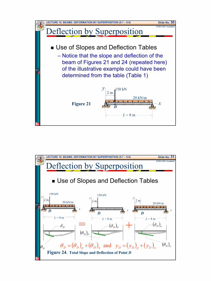
Use of Slopes and Deflection Tables– Notice that the slope and deflection of the
beam of Figures 21 and 24 (repeated here) of the illustrative example could have been determined from the table (Table 1)
x
y 150 kN
20 kN/m
L = 8 m
2 m
D•Figure 21
LECTURE 19. BEAMS: DEFORMATION BY SUPERPOSITION (9.7 – 9.8) Slide No. 31ENES 220 ©Assakkaf
Use of Slopes and Deflection Tables
x
y150 kN
20 kN/m
L = 8 m
2 m
x
y150 kN
L = 8 m
2 m
x
y
20 kN/m
L = 8 m
= +
Figure 24. Total Slope and Deflection of Point D
D D D
2 m
Dδ ( )PDδ ( )wDδ
( ) ( ) ( ) ( )wDpDDwDpDD yyy +=+= and θθθDθ
( )wDθ
( )PDθ
Deflection by Superposition
17
LECTURE 19. BEAMS: DEFORMATION BY SUPERPOSITION (9.7 – 9.8) Slide No. 32ENES 220 ©Assakkaf
Deflection by Superposition
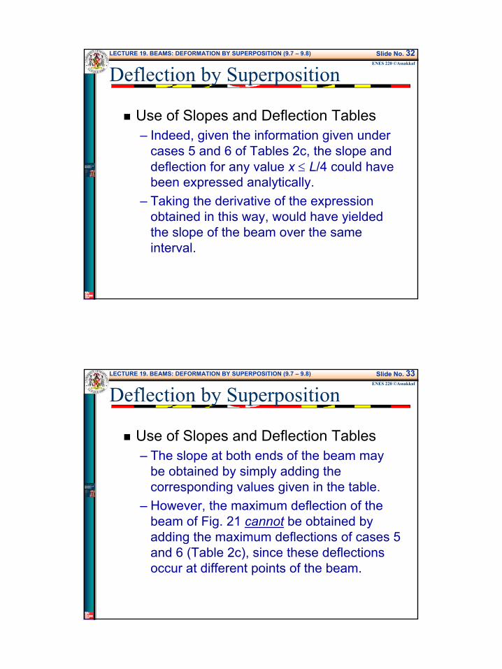
Use of Slopes and Deflection Tables– Indeed, given the information given under
cases 5 and 6 of Tables 2c, the slope and deflection for any value x ≤ L/4 could have been expressed analytically.
– Taking the derivative of the expression obtained in this way, would have yielded the slope of the beam over the same interval.
LECTURE 19. BEAMS: DEFORMATION BY SUPERPOSITION (9.7 – 9.8) Slide No. 33ENES 220 ©Assakkaf
Deflection by Superposition
Use of Slopes and Deflection Tables– The slope at both ends of the beam may
be obtained by simply adding the corresponding values given in the table.
– However, the maximum deflection of the beam of Fig. 21 cannot be obtained by adding the maximum deflections of cases 5 and 6 (Table 2c), since these deflections occur at different points of the beam.

18
LECTURE 19. BEAMS: DEFORMATION BY SUPERPOSITION (9.7 – 9.8) Slide No. 34ENES 220 ©Assakkaf
Deflection by Superposition
Use of Slopes and Deflection Tables– Applying case 5 on the illustrative example
to find both the slope and deflection of point D of the beam (Fig. 21), yields
– These values confirm the results obtained using Eq. 25 of the integration method.
( ) ( )[ ] ( )( ) ( )( )[ ]
( ) ( )[ ] ( )( ) ( )[ ] rad 003.068)2(38101006)6(101503
6
m 009.026828101006)6(10150
6
2226
3222
2236
3223
−=−−××
=−−==
−=−−××
=−−=
bLxEILPb
dxdy
xbLxEILPby
PD
PD
θ
LECTURE 19. BEAMS: DEFORMATION BY SUPERPOSITION (9.7 – 9.8) Slide No. 35ENES 220 ©Assakkaf
Deflection by Superposition
Example 6Use the method of superposition to find the slope and deflection at point B of the beam.
x
y
wA C B
2L
2L
19
LECTURE 19. BEAMS: DEFORMATION BY SUPERPOSITION (9.7 – 9.8) Slide No. 36ENES 220 ©Assakkaf
Deflection by Superposition
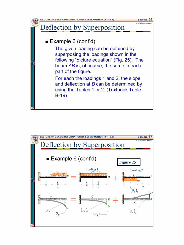
Example 6 (cont’d)The given loading can be obtained by superposing the loadings shown in the following “picture equation” (Fig. 25). The beam AB is, of course, the same in each part of the figure.For each the loadings 1 and 2, the slope and deflection at B can be determined by using the Tables 1 or 2. (Textbook Table B-19)
LECTURE 19. BEAMS: DEFORMATION BY SUPERPOSITION (9.7 – 9.8) Slide No. 37ENES 220 ©Assakkaf
Deflection by Superposition
Example 6 (cont’d)Figure 25
wA C B
2L
2L
= wA C B
2L
2L
= +
+
A C
ByBθ
AC
B
( )1By( )1Bθ
AC
B
( )2By
( )2Bθ
wA
CB
2L
2L
Loading 1 Loading 2
20
LECTURE 19. BEAMS: DEFORMATION BY SUPERPOSITION (9.7 – 9.8) Slide No. 38ENES 220 ©AssakkafProblem 6 (cont’d)
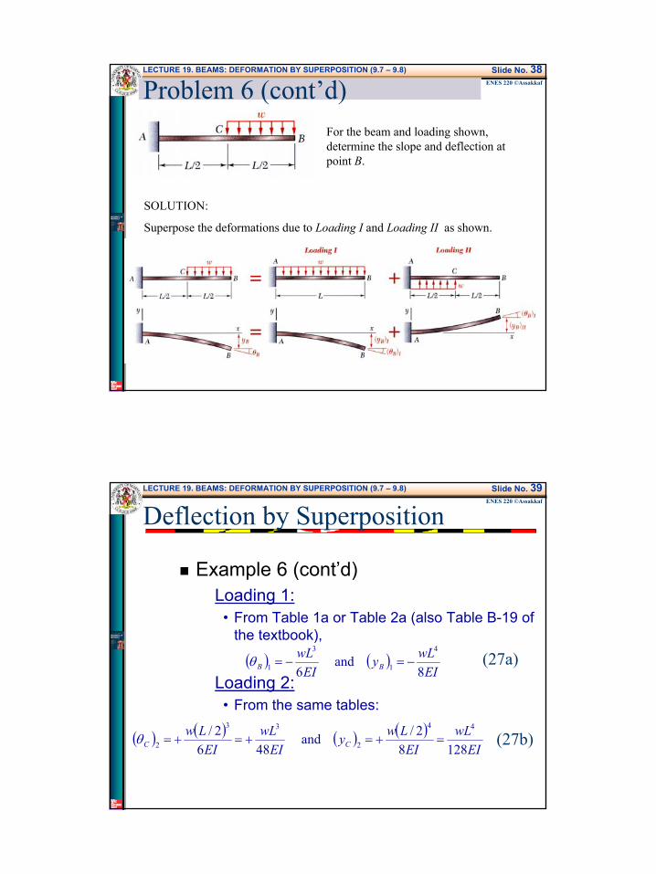
For the beam and loading shown, determine the slope and deflection at point B.
SOLUTION:
Superpose the deformations due to Loading I and Loading II as shown.
LECTURE 19. BEAMS: DEFORMATION BY SUPERPOSITION (9.7 – 9.8) Slide No. 39ENES 220 ©Assakkaf
Deflection by Superposition
Example 6 (cont’d)Loading 1:
• From Table 1a or Table 2a (also Table B-19 of the textbook),
Loading 2:• From the same tables:
( ) ( )EI
wLyEI
wLBB 8
and 6
4
1
3
1 −=−=θ (27a)
( ) ( ) ( ) ( )EI
wLEI
LwyEI
wLEI
LwCC 1288
2/ and 486
2/ 44
2
33
2 =+=+=+=θ (27b)
21
LECTURE 19. BEAMS: DEFORMATION BY SUPERPOSITION (9.7 – 9.8) Slide No. 40ENES 220 ©Assakkaf
Deflection by Superposition
Example 6 (cont’d)
wA
C B
2L
2L
AC
B
( )2By
( )2Bθ( )2Cθ
( )2Cy
( )2Cy
2L
( )2BySlope = ( )2Cθ
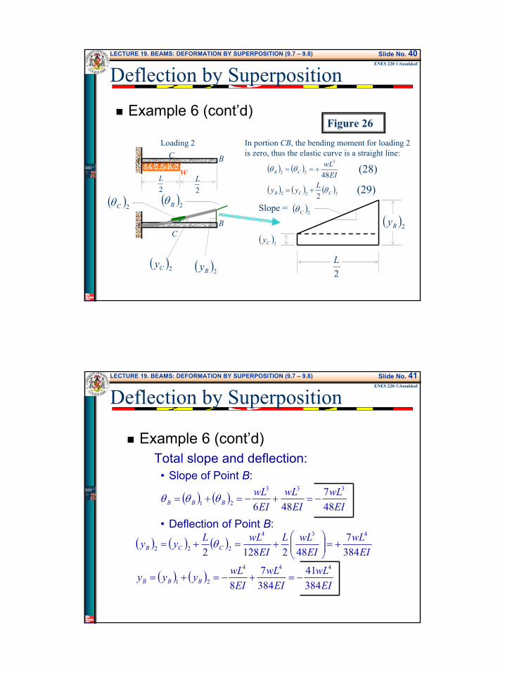
In portion CB, the bending moment for loading 2is zero, thus the elastic curve is a straight line:
( ) ( )
( ) ( ) ( )222
3
22
2
48
CCB
CB
Lyy
EIwL
θ
θθ
+=
+== (28)
(29)
Loading 2
Figure 26
LECTURE 19. BEAMS: DEFORMATION BY SUPERPOSITION (9.7 – 9.8) Slide No. 41ENES 220 ©Assakkaf
Deflection by Superposition
Example 6 (cont’d)Total slope and deflection:
• Slope of Point B:
• Deflection of Point B:
( ) ( )EI
wLEI
wLEI
wLBBB 48
7486
333
21 −=+−=+= θθθ
( ) ( ) ( )
( ) ( )EI
wLEI
wLEI
wLyyy
EIwL
EIwLL
EIwLLyy
BBB
CCB
38441
3847
8
3847
4821282444
21
434
222
−=+−=+=
+=
+=+= θ
22
LECTURE 19. BEAMS: DEFORMATION BY SUPERPOSITION (9.7 – 9.8) Slide No. 42ENES 220 ©Assakkaf
Deflection by Superposition
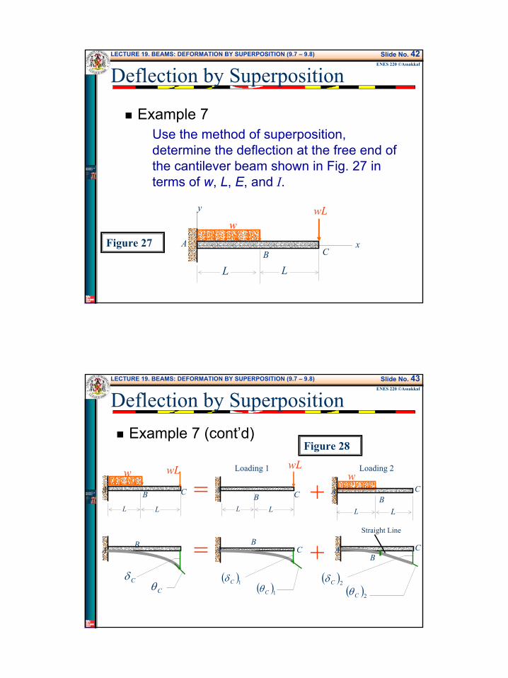
Example 7Use the method of superposition, determine the deflection at the free end of the cantilever beam shown in Fig. 27 in terms of w, L, E, and I.
x
y
wA
CB
LL
wL
Figure 27
LECTURE 19. BEAMS: DEFORMATION BY SUPERPOSITION (9.7 – 9.8) Slide No. 43ENES 220 ©Assakkaf
Deflection by SuperpositionExample 7 (cont’d)
wA
BC
L
Figure 28
L
=
= +
+
A B
CδCθ
AB
C
( )1Cδ( )1Cθ
Loading 1 Loading 2wL
AB C
LL
wA CB
LL
wL
AB
C
( )2Cδ( )2Cθ
Straight Line

23
LECTURE 19. BEAMS: DEFORMATION BY SUPERPOSITION (9.7 – 9.8) Slide No. 44ENES 220 ©Assakkaf
Deflection by Superposition
Example 7 (cont’d)Using the solutions listed in Table 1a. Cases 1 and 2 (Textbook Table B-19) with P = wL
( ) ( ) ( ) ( ) ( )
( )EI
wLEI
wLLEI
wLEI
LwL
EIwLL
EIwL
EILP
L BBCCCC
2471
6832
683)2(
4343
343
22121
−=
−−+−=
−−+−=
++=+= θδδδδδ
LECTURE 19. BEAMS: DEFORMATION BY SUPERPOSITION (9.7 – 9.8) Slide No. 45ENES 220 ©Assakkaf
Deflection by Superposition
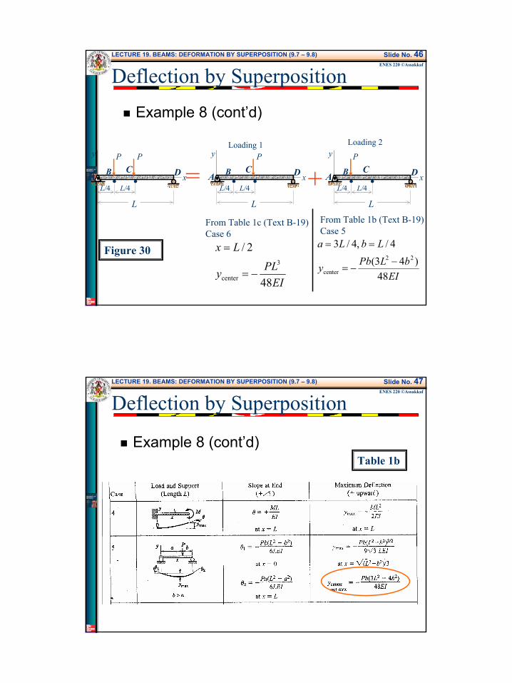
Example 8For the simply supported beam of Fig. 29, use the method of superposition to determine the total deflection at point C in terms of P, L, E, and I.
x
y P
L
L/4B• •C
L/4
P
A DFigure 29
24
LECTURE 19. BEAMS: DEFORMATION BY SUPERPOSITION (9.7 – 9.8) Slide No. 46ENES 220 ©Assakkaf
Deflection by Superposition
Example 8 (cont’d)
x
y P
L
L/4
B• •C
L/4
P
A D x
y P
L
L/4
B• •C
L/4A D x
y
L
L/4
B• •C
L/4
P
A D= +
Figure 30
From Table 1c (Text B-19)Case 6
EIPLy
Lx
48
2/3
center −=
=
From Table 1b (Text B-19)Case 5
EIbLPby
LbLa
48)43(
4/ ,4/322
center−
−=
==
Loading 1 Loading 2
LECTURE 19. BEAMS: DEFORMATION BY SUPERPOSITION (9.7 – 9.8) Slide No. 47ENES 220 ©Assakkaf
Example 8 (cont’d)Table 1b
Deflection by Superposition
25
LECTURE 19. BEAMS: DEFORMATION BY SUPERPOSITION (9.7 – 9.8) Slide No. 48ENES 220 ©Assakkaf
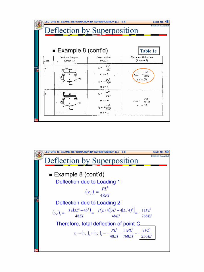
Example 8 (cont’d) Table 1c
Deflection by Superposition
LECTURE 19. BEAMS: DEFORMATION BY SUPERPOSITION (9.7 – 9.8) Slide No. 49ENES 220 ©Assakkaf
Deflection by SuperpositionExample 8 (cont’d)Deflection due to Loading 1:
Deflection due to Loading 2:
Therefore, total deflection of point C
( )EI
PLyC 48
3
1 =
( ) ( ) ( ) ( )[ ]EI
PLEI
LLLPEI
bLPbyC 76811
484/434/
4843 32222
2 −=−
−=−
−=
( ) ( )EI
PLEI
PLEI
PLyyy CCC 2569
76811
48
333
21 −=−−=+=

26
LECTURE 19. BEAMS: DEFORMATION BY SUPERPOSITION (9.7 – 9.8) Slide No. 50ENES 220 ©Assakkaf
Deflection by Superposition
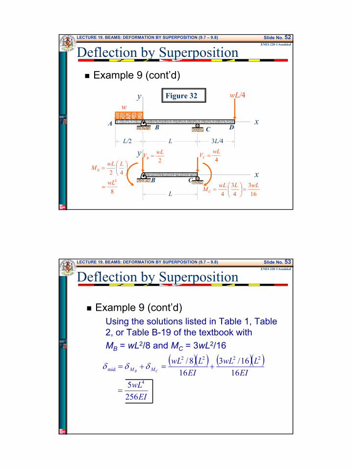
Example 9Using the method of superposition, find the deflection at a point midway between the supports of the beam shown in the figure in terms of w, L, E, and I.
x
y wL/4
L
B CA D
3L/4L/2
w
Figure 31
LECTURE 19. BEAMS: DEFORMATION BY SUPERPOSITION (9.7 – 9.8) Slide No. 51ENES 220 ©Assakkaf
Deflection by Superposition
Example 9 (cont’d)The deflection at a point midway between the supports can be determined by considering the beam shown in Fig. 32.Note that since the shear forces VB and VCdo not contribute to the deflection at any point in span BC, the mid-span deflection can be expressed as
CB MM δδδ +=mid (28)
27
LECTURE 19. BEAMS: DEFORMATION BY SUPERPOSITION (9.7 – 9.8) Slide No. 52ENES 220 ©Assakkaf
Deflection by SuperpositionExample 9 (cont’d)
x
y wL/4
L
B CA D
3L/4L/2
w
x
y
L
B C
4wLVC =
163
43
4wLLwLM C =
=
2wLVB =
8
422wL
LwLM B
=
=
Figure 32
LECTURE 19. BEAMS: DEFORMATION BY SUPERPOSITION (9.7 – 9.8) Slide No. 53ENES 220 ©Assakkaf
Deflection by Superposition
Example 9 (cont’d)Using the solutions listed in Table 1, Table 2, or Table B-19 of the textbook withMB = wL2/8 and MC = 3wL2/16
( )( ) ( )( )
EIwL
EILwL
EILwL
CB MM
2565
1616/3
168/
4
2222
mid
=
+=+= δδδ
28
LECTURE 19. BEAMS: DEFORMATION BY SUPERPOSITION (9.7 – 9.8) Slide No. 54ENES 220 ©Assakkaf
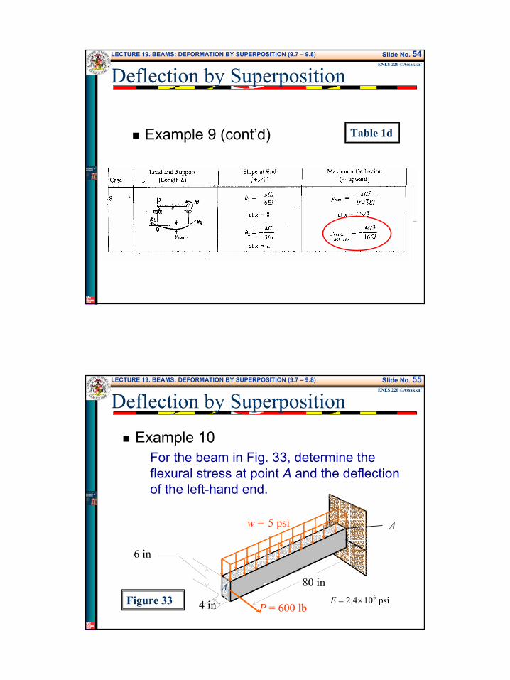
Example 9 (cont’d) Table 1d
Deflection by Superposition
LECTURE 19. BEAMS: DEFORMATION BY SUPERPOSITION (9.7 – 9.8) Slide No. 55ENES 220 ©Assakkaf
Deflection by Superposition
Example 10For the beam in Fig. 33, determine the flexural stress at point A and the deflection of the left-hand end.
Figure 33
w = 5 psi
P = 600 lb
Apsi 104.2 6×=E
80 in
6 in
4 in
A
29
LECTURE 19. BEAMS: DEFORMATION BY SUPERPOSITION (9.7 – 9.8) Slide No. 56ENES 220 ©Assakkaf
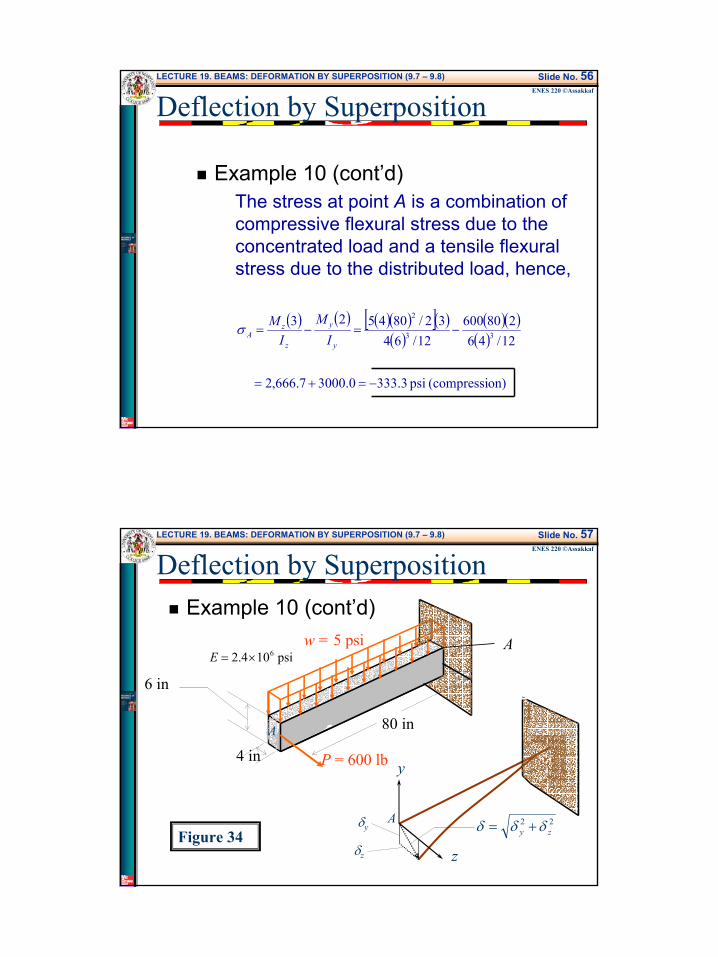
Deflection by Superposition
Example 10 (cont’d)The stress at point A is a combination of compressive flexural stress due to the concentrated load and a tensile flexural stress due to the distributed load, hence,
( ) ( ) ( )( )[ ]( )( )
( )( )( )
on)(compressi psi 3.3330.30007.666,2
12/46
28060012/64
32/80452333
2
−=+=
−=−=y
y
z
zA I
MI
Mσ
LECTURE 19. BEAMS: DEFORMATION BY SUPERPOSITION (9.7 – 9.8) Slide No. 57ENES 220 ©Assakkaf
Deflection by SuperpositionExample 10 (cont’d)
w = 5 psi
P = 600 lb
A
psi 104.2 6×=E
80 in
6 in
4 in
A
y
z
Aδy
δz
22zy δδδ +=
Figure 34
30
LECTURE 19. BEAMS: DEFORMATION BY SUPERPOSITION (9.7 – 9.8) Slide No. 58ENES 220 ©Assakkaf
Deflection by Superposition
Example 10 (cont’d)The deflection at the end of a cantilever beam with uniformly distributed load is given by (see Table 1a, case 2)
and with concentrated load at the end is given by (see Table 1a, case 1)
( )( )( ) ( )[ ] in 5926.0
12/64 104.288045
8 36
44
0 =×
==zEI
wLy
( )( ) ( )[ ] in 3333.1
12/46 104.2380600
3 36
33
0 =×
==EI
PLz
LECTURE 19. BEAMS: DEFORMATION BY SUPERPOSITION (9.7 – 9.8) Slide No. 59ENES 220 ©Assakkaf
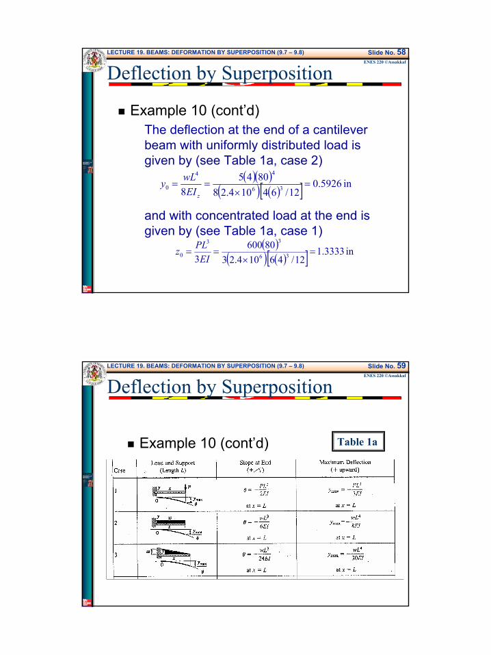
Example 10 (cont’d) Table 1a
Deflection by Superposition
31
LECTURE 19. BEAMS: DEFORMATION BY SUPERPOSITION (9.7 – 9.8) Slide No. 60ENES 220 ©Assakkaf
Deflection by Superposition
Example 10 (cont’d)Superimposing the results for the deflections due to the concentrated and distributed loads, the deflection at the free end is the vector sum:
( ) ( )
in 447.1
3333.15626.0 2220
20
=
+=+= zyδ
LECTURE 19. BEAMS: DEFORMATION BY SUPERPOSITION (9.7 – 9.8) Slide No. 61ENES 220 ©Assakkaf
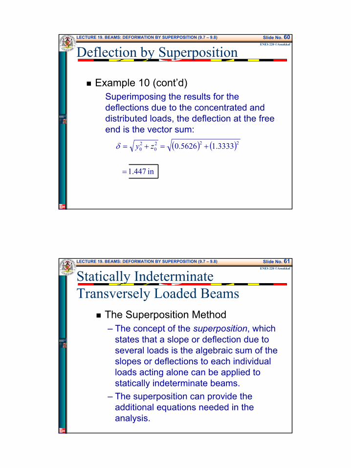
Statically Indeterminate Transversely Loaded Beams
The Superposition Method– The concept of the superposition, which
states that a slope or deflection due to several loads is the algebraic sum of the slopes or deflections to each individual loads acting alone can be applied to statically indeterminate beams.
– The superposition can provide the additional equations needed in the analysis.
32
LECTURE 19. BEAMS: DEFORMATION BY SUPERPOSITION (9.7 – 9.8) Slide No. 62ENES 220 ©Assakkaf
Statically Indeterminate Transversely Loaded Beams
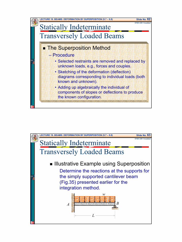
The Superposition Method– Procedure
• Selected restraints are removed and replaced by unknown loads, e.g., forces and couples.
• Sketching of the deformation (deflection) diagrams corresponding to individual loads (both known and unknown).
• Adding up algebraically the individual of components of slopes or deflections to produce the known configuration.
LECTURE 19. BEAMS: DEFORMATION BY SUPERPOSITION (9.7 – 9.8) Slide No. 63ENES 220 ©Assakkaf
Statically Indeterminate Transversely Loaded Beams
Illustrative Example using SuperpositionDetermine the reactions at the supports for the simply supported cantilever beam (Fig.35) presented earlier for the integration method.
w
A B
L
33
LECTURE 19. BEAMS: DEFORMATION BY SUPERPOSITION (9.7 – 9.8) Slide No. 64ENES 220 ©Assakkaf
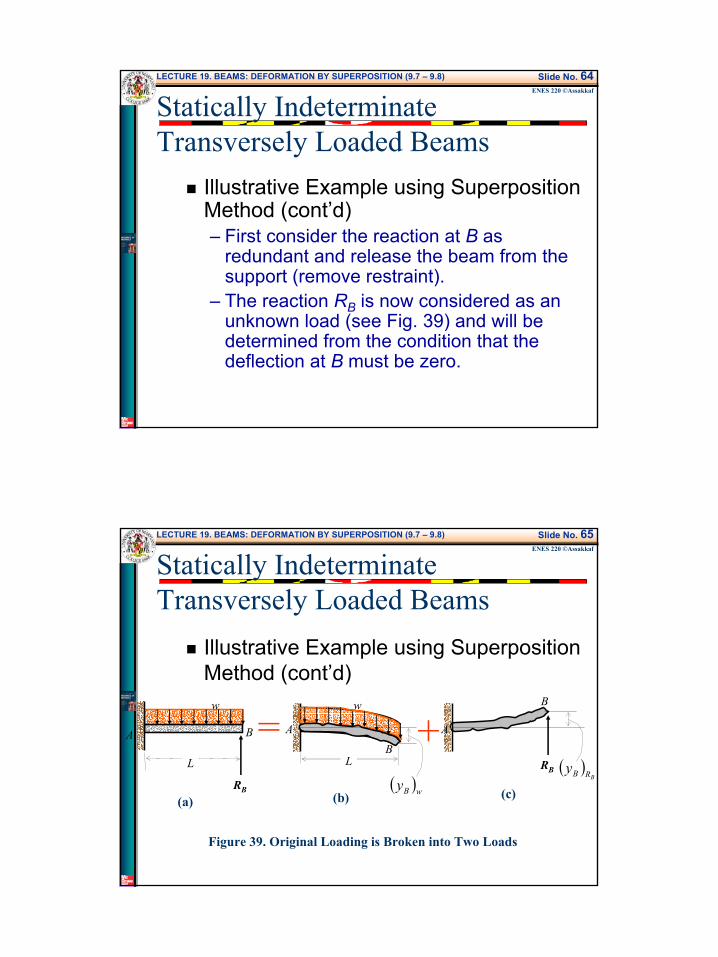
Illustrative Example using Superposition Method (cont’d)– First consider the reaction at B as
redundant and release the beam from the support (remove restraint).
– The reaction RB is now considered as an unknown load (see Fig. 39) and will be determined from the condition that the deflection at B must be zero.
Statically Indeterminate Transversely Loaded Beams
LECTURE 19. BEAMS: DEFORMATION BY SUPERPOSITION (9.7 – 9.8) Slide No. 65ENES 220 ©Assakkaf
Illustrative Example using Superposition Method (cont’d)
Figure 39. Original Loading is Broken into Two Loads
w
A B
L
RB
w
A
BL
( )wByRB
A
B
( )BRBy
= +(a) (b) (c)
Statically Indeterminate Transversely Loaded Beams
34
LECTURE 19. BEAMS: DEFORMATION BY SUPERPOSITION (9.7 – 9.8) Slide No. 66ENES 220 ©AssakkafApplication of Superposition to Statically
Indeterminate Beams
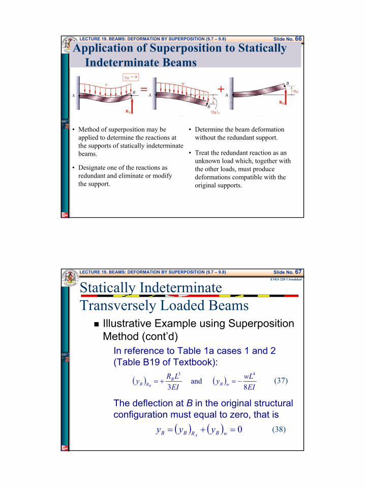
• Method of superposition may be applied to determine the reactions at the supports of statically indeterminate beams.
• Designate one of the reactions as redundant and eliminate or modify the support.
• Determine the beam deformation without the redundant support.
• Treat the redundant reaction as an unknown load which, together with the other loads, must produce deformations compatible with the original supports.
LECTURE 19. BEAMS: DEFORMATION BY SUPERPOSITION (9.7 – 9.8) Slide No. 67ENES 220 ©Assakkaf
Illustrative Example using Superposition Method (cont’d)
In reference to Table 1a cases 1 and 2 (Table B19 of Textbook):
The deflection at B in the original structural configuration must equal to zero, that is
( ) ( )EI
wLyEILRy wB
BRB B 8
and 3
43
−=+=
( ) ( ) 0=+= wBRBB yyyA
(37)
(38)
Statically Indeterminate Transversely Loaded Beams
35
LECTURE 19. BEAMS: DEFORMATION BY SUPERPOSITION (9.7 – 9.8) Slide No. 68ENES 220 ©Assakkaf
Slopes and Deflection Tables Table 1a
Statically Indeterminate Transversely Loaded Beams
LECTURE 19. BEAMS: DEFORMATION BY SUPERPOSITION (9.7 – 9.8) Slide No. 69ENES 220 ©Assakkaf
Illustrative Example using Superposition Method (cont’d)
Substituting Eq. 37 into Eq. 38, gives
Solving for RB, the result is
083
43
=−+EI
wLEILRB (39)
wLRB 83
+= (40)
Statically Indeterminate Transversely Loaded Beams
36
LECTURE 19. BEAMS: DEFORMATION BY SUPERPOSITION (9.7 – 9.8) Slide No. 70ENES 220 ©Assakkaf
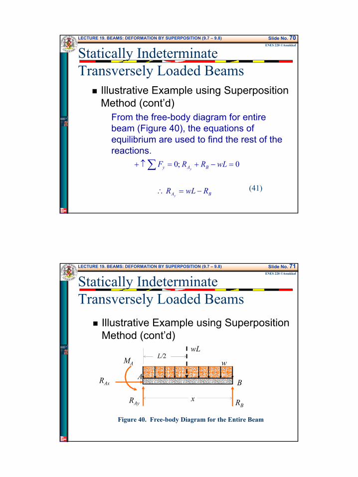
Illustrative Example using Superposition Method (cont’d)
From the free-body diagram for entire beam (Figure 40), the equations of equilibrium are used to find the rest of the reactions.
BA
BAy
RwLR
wLRRF
y
y
−=∴
=−+=↑+ ∑
0 ;0
(41)
Statically Indeterminate Transversely Loaded Beams
LECTURE 19. BEAMS: DEFORMATION BY SUPERPOSITION (9.7 – 9.8) Slide No. 71ENES 220 ©Assakkaf
Illustrative Example using Superposition Method (cont’d)
w
AB
wL
RBRAy
RAx
MAL/2
x
Figure 40. Free-body Diagram for the Entire Beam
Statically Indeterminate Transversely Loaded Beams
37
LECTURE 19. BEAMS: DEFORMATION BY SUPERPOSITION (9.7 – 9.8) Slide No. 72ENES 220 ©Assakkaf
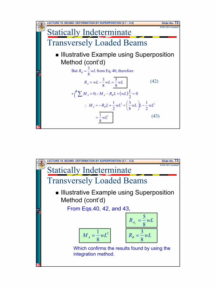
Illustrative Example using Superposition Method (cont’d)
( )
2
22
81
21
83
21
02
- ;0
85
83
therefore40, Eq. from 83But
wL
wLLwLwLLRM
LwLLRMM
wLwLwLR
wLR
BA
BAA
A
B
=
−
=+−=∴
=+−=+
=−=
=
∑
(42)
(43)
Statically Indeterminate Transversely Loaded Beams
LECTURE 19. BEAMS: DEFORMATION BY SUPERPOSITION (9.7 – 9.8) Slide No. 73ENES 220 ©Assakkaf
Illustrative Example using Superposition Method (cont’d)
From Eqs.40, 42, and 43,
Which confirms the results found by using the integration method.
wLRwLM
wLRR
BA
AA yx
83
81
85 0
2 ==
==
Statically Indeterminate Transversely Loaded Beams
38
LECTURE 19. BEAMS: DEFORMATION BY SUPERPOSITION (9.7 – 9.8) Slide No. 74ENES 220 ©Assakkaf
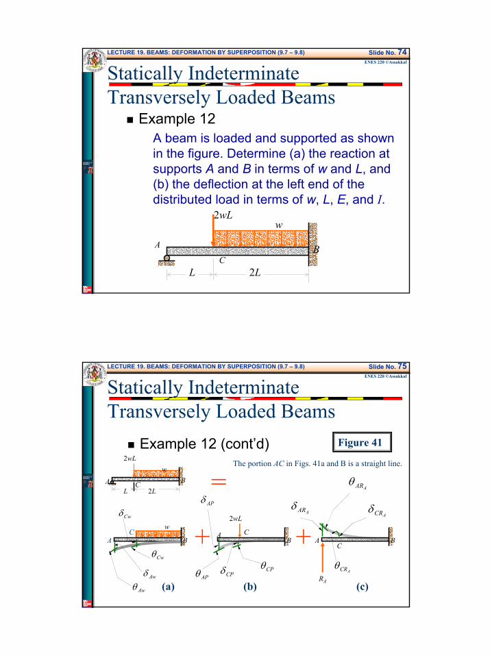
Example 12A beam is loaded and supported as shown in the figure. Determine (a) the reaction at supports A and B in terms of w and L, and (b) the deflection at the left end of the distributed load in terms of w, L, E, and I.
w
A B
2LC
L
2wL
Statically Indeterminate Transversely Loaded Beams
LECTURE 19. BEAMS: DEFORMATION BY SUPERPOSITION (9.7 – 9.8) Slide No. 75ENES 220 ©Assakkaf
Example 12 (cont’d)w
A B2L
CL
2wL
=
+ + A BC
AARδACRδ
AARθ
ACRθRA
BC
2wL
APδ
CPδ CPθ
A
APθ
w
B
Awδ
Cwδ
Awθ
CwθA
C
Figure 41
(a) (b) (c)
The portion AC in Figs. 41a and B is a straight line.
Statically Indeterminate Transversely Loaded Beams
39
LECTURE 19. BEAMS: DEFORMATION BY SUPERPOSITION (9.7 – 9.8) Slide No. 76ENES 220 ©Assakkaf
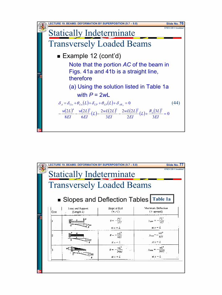
Example 12 (cont’d)Note that the portion AC of the beam in Figs. 41a and 41b is a straight line, therefore(a) Using the solution listed in Table 1a
with P = 2wL( ) ( )
( ) ( ) ( ) ( ) ( ) ( ) ( ) 03
32
223
2262
82
032334
=+−−−−
=++++=
EILRL
EILwL
EILwLL
EILw
EILw
LL
A
ARCPCPCwCwA Aδθδθδδ (44)
Statically Indeterminate Transversely Loaded Beams
LECTURE 19. BEAMS: DEFORMATION BY SUPERPOSITION (9.7 – 9.8) Slide No. 77ENES 220 ©Assakkaf
Slopes and Deflection Tables Table 1a
Statically Indeterminate Transversely Loaded Beams
40
LECTURE 19. BEAMS: DEFORMATION BY SUPERPOSITION (9.7 – 9.8) Slide No. 78ENES 220 ©Assakkaf
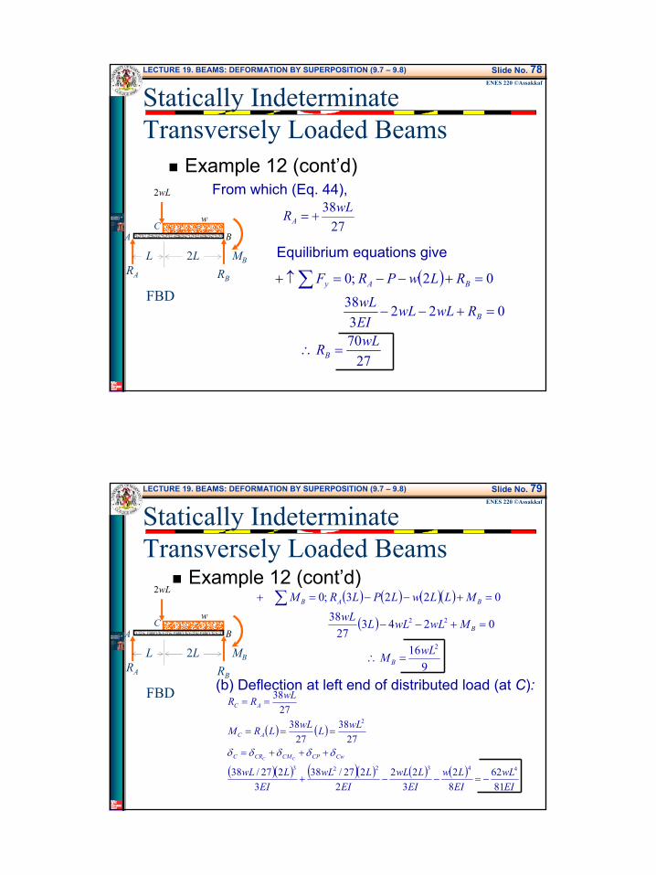
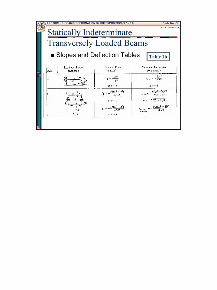
Example 12 (cont’d)From which (Eq. 44),
Equilibrium equations give
2738wLRA +=
( )
2770
0223
38
02 ;0
wLR
RwLwLEIwL
RLwPRF
B
B
BAy
=∴
=+−−
=+−−=↑+ ∑
w
BAC
RA RB
MB
2wL
FBD
2LL
Statically Indeterminate Transversely Loaded Beams
LECTURE 19. BEAMS: DEFORMATION BY SUPERPOSITION (9.7 – 9.8) Slide No. 79ENES 220 ©Assakkaf
Example 12 (cont’d)
(b) Deflection at left end of distributed load (at C):
( ) ( ) ( )( )
( )
916
024327
38
0223 ;0
2
22
wLM
MwLwLLwLMLLwLPLRM
B
B
BAB
=∴
=+−−
=+−−=+ ∑w
BAC
RA RB
MB
2wL
FBD
2LL
( ) ( )
( )( ) ( )( ) ( ) ( )EIwL
EILw
EILwL
EILwL
EILwL
wLLwLLRM
wLRR
CwCPCMCRC
AC
AC
CC
8162
82
322
2227/38
3227/38
2738
2738
2738
443223
2
−=−−+
+++=
===
==
δδδδδ
Statically Indeterminate Transversely Loaded Beams
41
LECTURE 19. BEAMS: DEFORMATION BY SUPERPOSITION (9.7 – 9.8) Slide No. 80ENES 220 ©Assakkaf
Slopes and Deflection Tables Table 1b
Statically Indeterminate Transversely Loaded Beams