behavior of massive earth retaining walls …se.sze.hu/images/ngb_se005_4/2_massive earth retaining...
TRANSCRIPT

BEHAVIOR OF MASSIVE EARTH RETAINING WALLS UNDER EARTHQUAKE SHAKING Comparisons to EC-8 Provisions
U N I V E R S I T Y O F P A T R A SD E P A R T M E N T O F C I V I L E N G I N E E R I N G
L a b o r a t o r y o f G e o t e c h n i c a l E n g i n e e r i n g
Győr, October 2015
Prof. G. AthanasopoulosV. Kitsis, MSc
V. Vlachakis, MScProf. A. Athanasopoulos – Zekkos
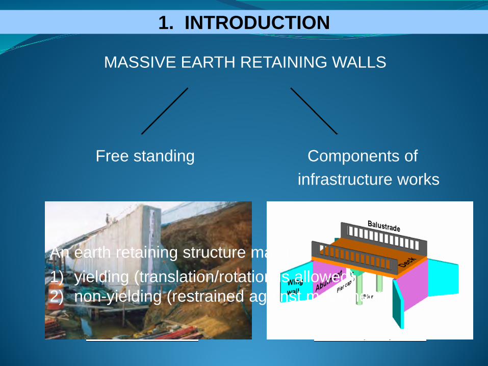
MASSIVE EARTH RETAINING WALLS
Free standing Components ofinfrastructure works
1. INTRODUCTION
An earth retaining structure may be:1) yielding (translation/rotation is allowed)2) non-yielding (restrained against movement)
1. INTRODUCTION
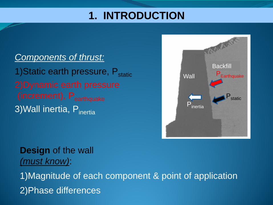
BackfillWall
Pstatic
PEarthquake
Pinertia
Components of thrust:1)Static earth pressure, Pstatic
2)Dynamic earth pressure(increment), Pearthquake
3)Wall inertia, Pinertia
Design of the wall(must know):1)Magnitude of each component & point of application2)Phase differences

2. YIELDING RETAINING WALLS
Harmonic excitationf = 3Hz, ag= 0.05g, 0.10g, 0.15g, 0.20g, 0.30g, 0.40g, 0.70g
Two cases were analyzed

Time histories of recorded earthquakes: a) Erzincan, Turkey, earthquake,(1992) & b) Loma Prieta, USA, earthquake (1989)
2. YIELDING RETAINING WALLS
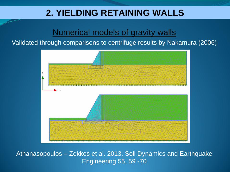
Numerical models of gravity wallsValidated through comparisons to centrifuge results by Nakamura (2006)
Athanasopoulos – Zekkos et al. 2013, Soil Dynamics and Earthquake Engineering 55, 59 -70
2. YIELDING RETAINING WALLS
2. YIELDING RETAINING WALLS
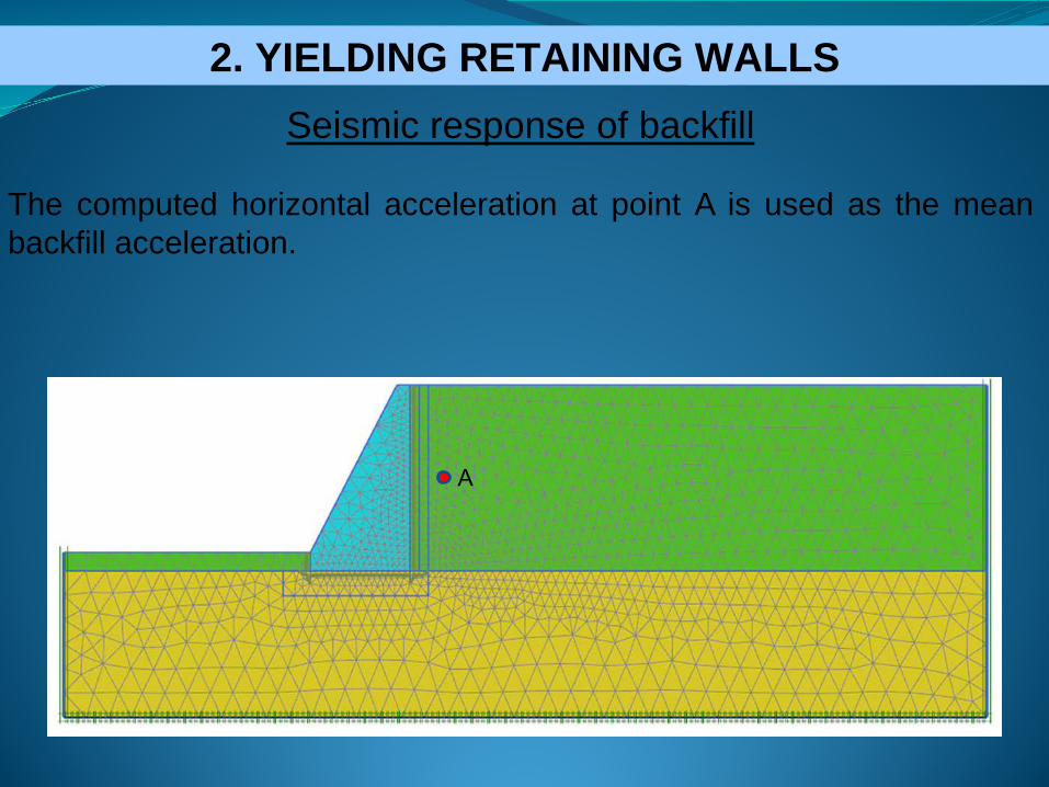
Seismic response of backfill
The computed horizontal acceleration at point A is used as the meanbackfill acceleration.
Α
2. YIELDING RETAINING WALLS

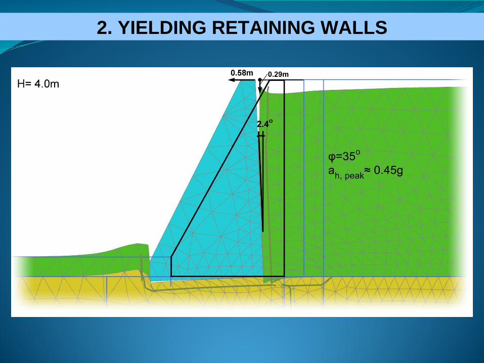
Seismic response of backfill for H = 4m
2. YIELDING RETAINING WALLS

2. YIELDING RETAINING WALLS
Seismic response of backfill for H = 7.5m

Distribution of computed peak active earth pressures along theheight of retaining walls and comparison with the M-O method.
2. YIELDING RETAINING WALLS
≈1/2≈1/2
Dyn. Increm. EC-8, Part 5,§ 7.3.2.3
Dyn. Increm. EC-8, Part 5,§ 7.3.2.3PNum ≈ PM-O
EC-8, Part 5, Annex E.4
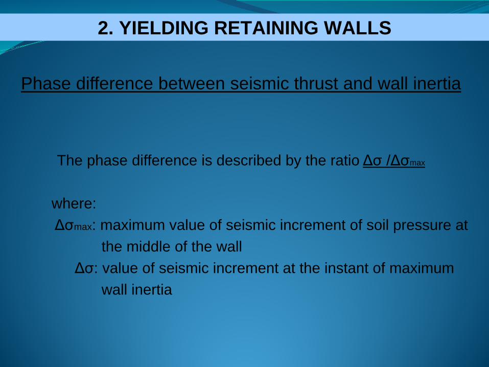
Phase difference between seismic thrust and wall inertia
The phase difference is described by the ratio Δσ /Δσmax
where:Δσmax: maximum value of seismic increment of soil pressure at
the middle of the wallΔσ: value of seismic increment at the instant of maximum
wall inertia
2. YIELDING RETAINING WALLS
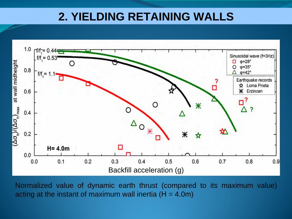
Normalized value of dynamic earth thrust (compared to its maximum value)acting at the instant of maximum wall inertia (Η = 4.0m)
Backfill acceleration (g)
2. YIELDING RETAINING WALLS

Backfill acceleration (g)
2. YIELDING RETAINING WALLS
Normalized value of dynamic earth thrust (compared to its maximum value)acting at the instant of maximum wall inertia (Η = 7.5m)

EC-8 Provisions
The numerical analyses indicate that the wall design could be based on a much reduced (r = 1.67 to 5) seismic increment, especially for
strong ground motions.
2. YIELDING RETAINING WALLS
Type of retaining structure r 1/r
Free gravity walls that can accept a displacement up to dr = 300aS (mm) 2 0.5
Free gravity walls that can accept a displacement up to dr = 200aS (mm) 1.5 0.67
Flexural reinforced concrete walls, anchored or braced walls, reinforced concrete walls founded on vertical
piles, restrained basement walls and bridge abutments1 1
3. ΑΡΙΘΜΗΤΙΚΗ ΠΡΟΣΟΜΟΙΩΣΗ
Υλικό επίχωσης E, v, γ, φ Tοίχος αντιστήριξης
Ε, ν, γ Η
ag
Συνθήκες πάκτωσης
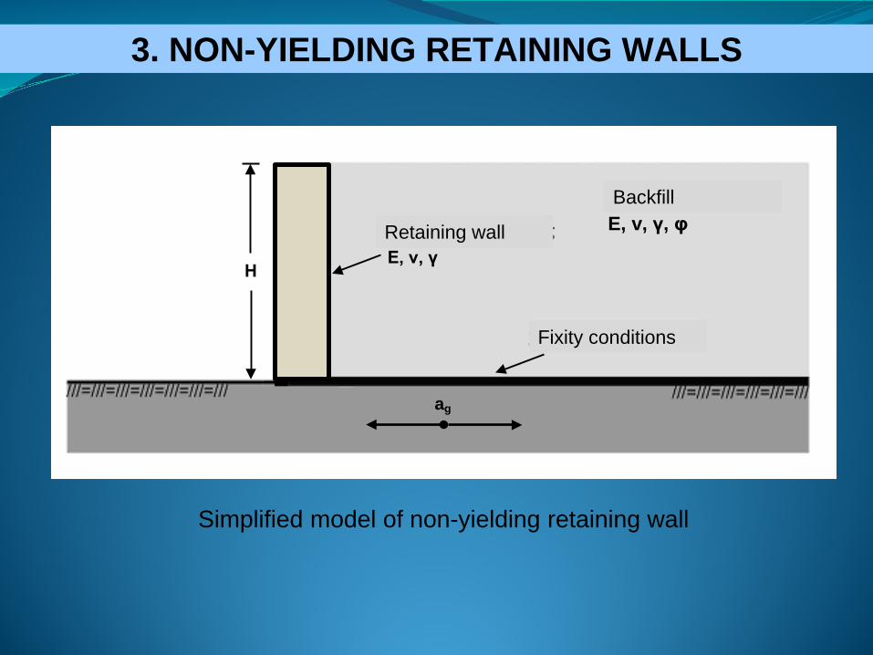
Simplified model of non-yielding retaining wall
3. ΑΝΕΝΔΟΤΟΙ ΤΟΙΧΟΙ ΕΔΑΦΙΚΗΣ ΑΝΤΙΣΤΗΡΙΞΗΣ3. NON-YIELDING RETAINING WALLS
Retaining wall
Backfill
Fixity conditions

Numerical model of non-yielding massive wall3. ΑΡΙΘΜΗΤΙΚΗ ΠΡΟΣΟΜΟΙΩΣΗ
Finite element mesh for wall height Η=4.0m
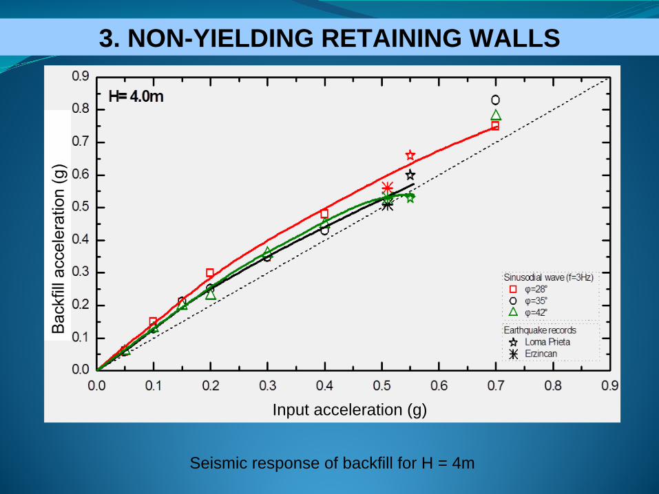
3. ΑΝΕΝΔΟΤΟΙ ΤΟΙΧΟΙ ΕΔΑΦΙΚΗΣ ΑΝΤΙΣΤΗΡΙΞΗΣ3. NON-YIELDING RETAINING WALLS
(v.2012.01)
4. ΑΠΟΤΕΛΕΣΜΑΤΑ ΠΑΡΑΜΕΤΡΙΚΩΝ ΑΝΑΛΥΣΕΩΝ3. ΑΝΕΝΔΟΤΟΙ ΤΟΙΧΟΙ ΕΔΑΦΙΚΗΣ ΑΝΤΙΣΤΗΡΙΞΗΣ3. NON-YIELDING RETAINING WALLS
Seismic response of backfill for H = 4m
Input acceleration (g)

4. ΑΠΟΤΕΛΕΣΜΑΤΑ ΠΑΡΑΜΕΤΡΙΚΩΝ ΑΝΑΛΥΣΕΩΝ3. ΑΝΕΝΔΟΤΟΙ ΤΟΙΧΟΙ ΕΔΑΦΙΚΗΣ ΑΝΤΙΣΤΗΡΙΞΗΣ3. NON-YIELDING RETAINING WALLS
Input acceleration (g)
Seismic response of backfill for H = 7.5m
4. ΑΠΟΤΕΛΕΣΜΑΤΑ ΠΑΡΑΜΕΤΡΙΚΩΝ ΑΝΑΛΥΣΕΩΝ
115.2kN/m199kN/m
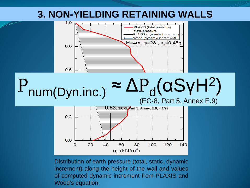
3. ΑΝΕΝΔΟΤΟΙ ΤΟΙΧΟΙ ΕΔΑΦΙΚΗΣ ΑΝΤΙΣΤΗΡΙΞΗΣ3. NON-YIELDING RETAINING WALLS
Distribution of earth pressure (total, static, dynamicincrement) along the height of the wall and valuesof computed dynamic increment from PLAXIS andWood’s equation.
0.53, (EC-8, Part 5, Annex E.9, = 1/2)
Pnum(Dyn.inc.) ≈ ΔPd(αSγH2)(EC-8, Part 5, Annex E.9)

4. ΑΠΟΤΕΛΕΣΜΑΤΑ ΠΑΡΑΜΕΤΡΙΚΩΝ ΑΝΑΛΥΣΕΩΝ
0.0
0.2
0.4
0.6
0.8
1.0
0 50 100 150 200 250 300
H=7.5m, φ=35ο, ah=0.5g
PLAXIS (total pressure) static pressure
PLAXIS (dynamic increment) Wood (dynamic increment)
σh (kN/m2)
h/H 773kN/m 708.75kN/m
Distribution of earth pressure (total, static, dynamicincrement) along the height of the wall and valuesof computed dynamic increment from PLAXIS andWood’s equation.
3. ΑΝΕΝΔΟΤΟΙ ΤΟΙΧΟΙ ΕΔΑΦΙΚΗΣ ΑΝΤΙΣΤΗΡΙΞΗΣ3. NON-YIELDING RETAINING WALLS
0.52, (EC-8, Part 5, Annex E.9, = 1/2)
Pnum(Dyn.inc.) ≈ ΔPd(αSγH2)(EC-8, Part 5, Annex E.9)

4. ΑΠΟΤΕΛΕΣΜΑΤΑ ΠΑΡΑΜΕΤΡΙΚΩΝ ΑΝΑΛΥΣΕΩΝ3. ΑΝΕΝΔΟΤΟΙ ΤΟΙΧΟΙ ΕΔΑΦΙΚΗΣ ΑΝΤΙΣΤΗΡΙΞΗΣ3. NON-YIELDING RETAINING WALLS
Normalized value of dynamic earth thrust (compared to its maximumvalue) acting at the instant of maximum wall inertia (Η = 4.0m)
4. ΑΠΟΤΕΛΕΣΜΑΤΑ ΠΑΡΑΜΕΤΡΙΚΩΝ ΑΝΑΛΥΣΕΩΝ3. ΑΝΕΝΔΟΤΟΙ ΤΟΙΧΟΙ ΕΔΑΦΙΚΗΣ ΑΝΤΙΣΤΗΡΙΞΗΣ3. NON-YIELDING RETAINING WALLS
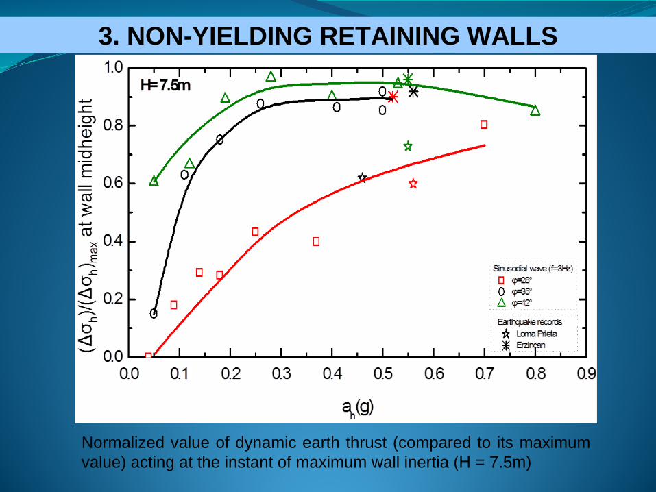
Normalized value of dynamic earth thrust (compared to its maximumvalue) acting at the instant of maximum wall inertia (Η = 7.5m)

EC-8 Provisions3. NON-YIELDING RETAINING WALLS
The numerical analyses indicate that the wall design could be based on the maximum value (r ≈ 1) of seismic increment,
especially for strong ground motions.
Type of retaining structure r 1/r
Free gravity walls that can accept a displacement up to dr = 300aS (mm) 2 0.5
Free gravity walls that can accept a displacement up to dr = 200aS (mm) 1.5 0.67
Flexural reinforced concrete walls, anchored or braced walls, reinforced concrete walls founded on vertical
piles, restrained basement walls and bridge abutments1 1

Comparison of the behavior of non-yielding and yielding retaining walls
4. ΑΠΟΤΕΛΕΣΜΑΤΑ ΠΑΡΑΜΕΤΡΙΚΩΝ ΑΝΑΛΥΣΕΩΝ
Non-yielding retaining walls
3. ΑΝΕΝΔΟΤΟΙ ΤΟΙΧΟΙ ΕΔΑΦΙΚΗΣ ΑΝΤΙΣΤΗΡΙΞΗΣ
Yielding retaining walls
3. NON-YIELDING RETAINING WALLS

4. CEPHALONIA EARTHQUAKES 2014

4. CEPHALONIA EARTHQUAKES 2014
Mw6.003/02/2014
Mw6.126/01/2014
0.76g (2nd)
(ARG2)PGA=0.43g (1st)PGA=0.27g (2nd)
(LXRB)PGA=0.54g (1st)PGA=0.68g (2nd)
(1st)
(2nd )

4. CEPHALONIA EARTHQUAKES 2014

4. CEPHALONIA EARTHQUAKES 2014
Cemeteries

4. ΑΝΤΙΚΕΙΜΕΝΟ ΠΕΡΑΙΤΕΡΩ ΕΡΕΥΝΑΣ4. CEPHALONIA EARTHQUAKES 2014
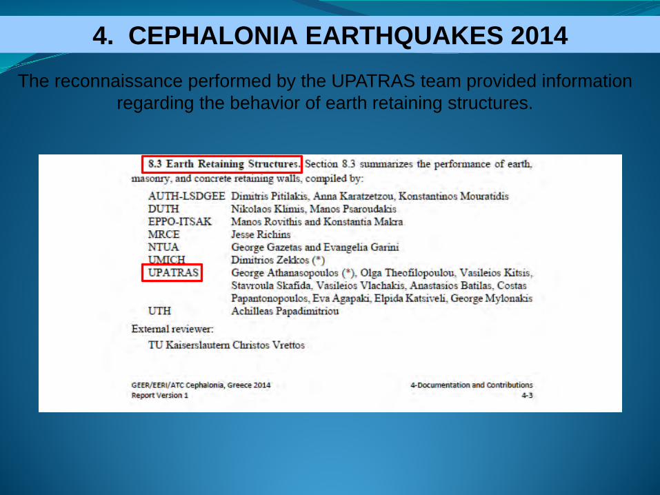
The reconnaissance performed by the UPATRAS team provided information regarding the behavior of earth retaining structures.
4. ΑΝΤΙΚΕΙΜΕΝΟ ΠΕΡΑΙΤΕΡΩ ΕΡΕΥΝΑΣ4. CEPHALONIA EARTHQUAKES 2014

1st Case study
• CONCRETE CANTILEVER RETAINING WALL
• Height: (varies from 0.6m to 2.5m)
• Measured horizontal displacement: 12cm
• Stem tilt: 2.5°
4. ΑΝΤΙΚΕΙΜΕΝΟ ΠΕΡΑΙΤΕΡΩ ΕΡΕΥΝΑΣ4. CEPHALONIA EARTHQUAKES 2014
4. ΑΝΤΙΚΕΙΜΕΝΟ ΠΕΡΑΙΤΕΡΩ ΕΡΕΥΝΑΣ4. CEPHALONIA EARTHQUAKES 2014

4. ΑΝΤΙΚΕΙΜΕΝΟ ΠΕΡΑΙΤΕΡΩ ΕΡΕΥΝΑΣ4. CEPHALONIA EARTHQUAKES 2014

4. ΑΝΤΙΚΕΙΜΕΝΟ ΠΕΡΑΙΤΕΡΩ ΕΡΕΥΝΑΣ
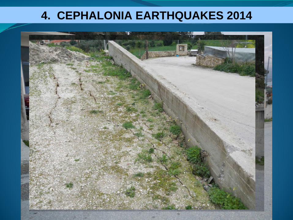
2nd Case study
• CONCRETE GRAVITY RETAINING WALL
• Height: (varies from 3.2m to 3.9m)
• Measured horizontal displacement: 4cm
• Measured vertical displacement: 7cm
• Crack opening in the retained roadway (extending to a length of 150m)
4. CEPHALONIA EARTHQUAKES 2014

4. ΑΝΤΙΚΕΙΜΕΝΟ ΠΕΡΑΙΤΕΡΩ ΕΡΕΥΝΑΣ4. CEPHALONIA EARTHQUAKES 2014

4. ΑΝΤΙΚΕΙΜΕΝΟ ΠΕΡΑΙΤΕΡΩ ΕΡΕΥΝΑΣ
3rd Case study
• MASONRY GRAVITY RETAINING WALL (flanked by concrete walls)
• Height: 3.3m
• Horizontal displacement: 21cm
• Vertical displacement: 20cm
• Cracks opening in the church’s front yard supported by the wall (extendingto a length of about 24m).
4. CEPHALONIA EARTHQUAKES 2014

4. ΑΝΤΙΚΕΙΜΕΝΟ ΠΕΡΑΙΤΕΡΩ ΕΡΕΥΝΑΣ4. CEPHALONIA EARTHQUAKES 2014

4. ΑΝΤΙΚΕΙΜΕΝΟ ΠΕΡΑΙΤΕΡΩ ΕΡΕΥΝΑΣ4. CEPHALONIA EARTHQUAKES 2014

Thank you !!Köszönöm !!