behavioral specification of a circuit using synccharts: a ......
TRANSCRIPT
Behavioral Specification of a Circuit Using SyncCharts:
a Case Study
C. ANDRÉ – M-A. PERALDI-FRATI
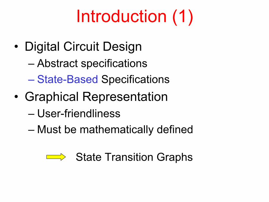
Introduction (1)• Digital Circuit Design
– Abstract specifications– State-Based Specifications
• Graphical Representation– User-friendliness– Must be mathematically defined
State Transition Graphs

Introduction (2)State Transition Graphs
• well-founded• but a flat model
Concurrency + preemptionSyncCharts
Expression of the
expected behavior
Validation:Test
Model-checking
Circuitoptimization

Plan• Introduction• Illustrative Example• Modular Specification with SyncCharts• Validation• Circuit Optimizations• Conclusion

Encoding/Decoding
BinTransmitter Receiv er
Bout
t
010000010 010000010
+U
-U0
encoding decoding
0+-00-0+0

Specification
encoding: {0,1} * → {-U, 0, +U} *decoding: {-U, 0, +U} * → {0,1} *
Requirement 1
11:
k n
kk
Un u=
=
∀ ≥ ≤∑Requirement 2
( ) ( ) ( ) ( )( )1 2 304 : 0 0 0n n n nn u u u u− − −∀ ≥ ¬ = ∧ = ∧ = ∧ =

Specification (Cnt’d)
encoding: {0,1} * → {n,z,p} *
decoding: {n,z,p} * → {0,1} *
In what follows: -U ↔ n; 0 ↔ z; +U ↔ p

Parity Violation
Encoding
Standard encoding:
4 successive 0:
0 → z 1 → {n,p} alternately
0 0 0 0 → P z z V

Example
Instant 1 2 3 4 5 6 7 8 9 10 11
x
u
Even
0
z
1
This system is not causal (depends on the future)
1
p
0
A
0
n
1
0
z
1
0
z
1
0
n
0
A V
0
z
1
0
z
1
0
z
1
0
p
0
A V
1
p
1
A

Making it causal
D D D
FourZeros
u’
x[k] x[k-3]x[k-1] x[k-2]
u’[k] = u[k-3]Delayed output:
Detection of 4 « 0 » in a rowStandard
Mealymachine

Classical Design
1
3
2
Legend:d f / u’
10/n
10/p
01/z
4
0-/z
5
0-/z
01/n
Violation
67
8
9
10
0-/p0-/p
0-/n
0-/z
0-/z
01/z 10/n
10/p
01/p
00/z 00/z
00/z00/z
(even) Parity (odd)
[Zahnd 1987]
• Try to find it!• d and f are not independent• Implicit shift register
•Well-structured•Easy to interpret
But …
A bright design …

SyncCharts-based Design• Decompose into interacting agents
– Detector (4 consecutive 0’s)– Parity manager– Sequence generator– Output manager
• Test on scenarios (Esterel Studio)• Prove safety properties• Circuit optimization (if HW controller)

Transmitter
@DETECTOR[..] @
EMITTER
@PARITY @
@NONZERO @
signal B3, Alternance, Violation, FourZeros, PlusOrMinus
ENCODER
where @DETECTOR[signal Bin/Bit0,B3/Bit3]

Detector
D0@DELAY[..] @ D1@DELAY[..] @ D2@DELAY[..] @
loop present Bit0 or Bit1 or Bit2 or Bit3 else emit FourZeros end presenteack tick
signal Bit1, Bit2
@DETECTOR[signal Bin/Bit0,B3/Bit3]
where D0@DELAY[signal Bit0/Ev, Bit1/DEv] D1@DELAY[signal Bit1/Ev, Bit2/DEv] D2@DELAY[signal Bit2/Ev, Bit3/DEv]

Emitter
present Even then emit Zeroelse emit Alternanceend present; pause;emit Zero; pause;emit Zero; pause;emit Violation; pause
EXCEPTION
loop present B3 then emit Alternance else emit Zero end presenteach tick
NORMAL
#FourZeros
EMITTER

Safety properties (1)
Observer: An esterel module
Property:At each instant : one and only one signalout of {n,z,p} is emitted
looppresent (n and not z and not p)
or (not n and z and not p)or (not n and not z and p)
elseemit non_exclusive
end presenteach tick

Safety properties (2)
Requirement 1:1
1:k n
kk
Un u=
=
∀ ≥ ≤∑
Observer: A flat syncChart = a FSM
TooNegative
n n n
p p p
-U 0 +U
TooPositive
OBSERVER_R1

Safety properties (3)
Observer: A syncChart with preemption
Requirement 2:
( ) ( ) ( ) ( )( )1 2 34 : n n n nn z z z zu u u u− − −
∀ ≥ ¬ = ∧ = ∧ = ∧ =
# z z
p or n
OBSERVER_R2
z
TooManyZ
z

Safety properties (4)
Beyond the sixth instant:Bout is identical to Bin, upto a 6 instant delay.
Encoder/Decoder:
Observer:
Encoder Decoderzp
n
6_stage_shift_register
Bin Bout
Violation
OBSERVER

PerformanceHigh-level behavioral description (e.g., encoder)
syncChart
esterel programStructural translation
blifEsterel’s compiler
optimized circuitSIS
105 states
35 states
As efficient as the hand-coded solution

Conclusion (1)• State-transition graphs
– Understandable even by non-specialists– Flat model → in-the-small
• SyncCharts =– State-transition graphs +
• Concurrency• Hierarchy• Preemption
– Can include Esterel code
higher level expression of behavior

Conclusion (2)« SyncCharts » is a Synchronous Formalism
• mathematical semantics
• safe code generation (ESTEREL)
• interactive simulation (XES)
• model-checking (XEVE)
• link to SIS
validation
efficient circuit
formal