bell system practices section 512-210-101 6017-, 6026
TRANSCRIPT

BELL SYSTEM PRACTICES AT& TCo Standard
SECTION 512-210-101 Issue 4 , April 1979
6017-, 6026-, KS-21254, AND KS-21776 TYPE SEPARATELY MOUNTED KEYS
IDENTIFICATION, INSTALLATION, AND CONNECTIONS
1. GENERAL
1.01 This section contains information on 6017, 6026, KS-21254 (MD), a nd • KS-21776t lever
type separately mounted keys.
1.02 This section is reissued to:
• Add information on KS-21776, Lists 1 through 9 keys
• Include schematic drawings of KS-21254, Lists 1 through 4 keys.
• Show KS-21254 type keys MD, replaced by certain KS-21776 type keys, Table n
• Show 6017A, B, C, D, TT, and ,J keys rated (A&M Only) Table A.
2. IDENTIFICATION
2 .01 These keys are refer red to as lever type and are used to perform general switching
functions in station equipment and systems.
A. Ordering Guide
2.02 Refer to Tables A a nd B for order ing information.
B. Design Features
2.03 6017-Type K ey (Fig. 1 ):
• Consists of a key unit and terminal strip mounted in a gray plastic housing
• Not equipped with a designation card holder. A 98A designation strip is available but must be ordered separate ly. Usc a 804768828 (P-476882) designation card or make from good grade of paper approximately 9/16-inch hy 5/16-inch.
Fig. 1- 6017-Type Keys
2.04 6026-Typc Key (Fig. 2):
• Consists of a key unit, jacks for a 52- or 53-type head telephone set, and a terminal strip mounted in a black metal housing
• This type key is supplied with a designation card holder. Use a E-1164 or E-1165 designation card (cut to size).
2.05 KS-212/H 'I'ype Key (MD) (Fig. S, 4, 5, or 6).
• Consists of a toggle switch (two or four pole), flexible wiring strip with 6 or 12 screw terminals for making electrical connections, and molded plastic cover held to base by serrated locking or hex nut at front (Fig. 3) and snap fit at the rear. Cover has a simplified schematic molded inside.
• Contacts are gold l)iated, suitable for voice a nd data transmission paths. Contacts a lso
NOTICE Not for use or disclosure out..•icle the
Bell System except under written agr<.'emrnt
Printed in U.S.A. Page 1

SECTION 512-210-101
Fig. 2 - 6026-Type Keys
satisfactory for low energy level circuits associated with solid state devices.
• Electrical cord channel is provided with four teeth- like protrusions which act as a cord stay to prevent cord from being dislodged (Fig. 4)
• Will mount on 77A moun ti n~ bracket (ordered separately) so key can be attached to baseplate of telephone set (Fig. 5 and 6)
• Key can he fastened to desk, wall, ete. by appropriate hardware not furnished with key.
2.06 •KS-21776 1'y p e Key (Fig. 7, 8, or 9).
• All list number keys (Table R) are available in two different types (A ann 13).
Page 2
(a) The1·e are two types of keys, one type (Fig. 8) consists of:
(1) Toggle switch (two or four pole).
SERRATED LOCKING NUT
H/41NCH APPROX.
Fig. 3 - KS-21254 Type Key (MD)
nA MOUNTING BRACKET AND SCREWS
CORD HOLD IN<; PROTRUSIONS (4)
"~
COVER (SIMPliFI ED SCHEMATIC INSIDE)
COVER LOC KING NUT
Fig. 4-KS-21254, list 4 Key (MD) Cover Removed and 77A Mounting Bracket

Fig. 5-KS-21254 Type Key (MD) Insta lled With 2500-Type Te lephone Set
Fig. 6 - lnterior View of KS-21254, List 4 Ke y (MD) Showing leads Terminate d
(2) Flexible wiring sLrip (six or twelve terminal.
(3) Electr ical cord channel is provided with four teeth-like proLrusions which act as a cord stay to prevent cord from being dis lodged.
Note: These keys can be mounted on 77 A mounLin~ bracket or can be fastcncfl to desk, wall, etc. by appropriaLe hardware. The bracket and hardware must be ordered separately or furnished locall~·.
ISS 4, SECTION 512-210-101
(b) The other type (Fig. 9) consists of.
(1) Toggle switch (two or four pole).
(2) Screw terminals (6 or 12).
(3) Auxiliary mounting bracket.
(1) Pan head mounting screws (2).
(5) Double-s ided adhesive tape (fastened to auxiliary mounting bracket).
Note: These keys are not intended to be mounted with the 77A mounting bracket.
All key oovel$ must be ordered separately (Ta ble B). A simplified schematic is provided on a stick-on decal which is furnished with each key and should be placed inside cover.
• Contacts of toggle switch on both type keys ar e gold plated and suitable for voice and data Lransmission paths. Contacts also satisfactory for low energy level ci rcuits associated wiLh solid state devices
• Replaces cerLain 6017- a nd KS-21254 type keys, refer to Table B .•
3. INSTALLATION
3 .01 601 7- or 6026-Type K eys.
(a) Loeatc key where readily accessible to user and designation strip can be seen.
(b) Face of key should be flush with edge of desk or table. Discourage knee well installations
because of space limitaLions and possible accident hazards.
(c) To limit number of holes in customer's fu rniture, key and associated equipment may
be mounted on a common backboarrl.
(d) Keys are furni shed for right-hand mounting on desk or k"lble. To mount 6017-type key
Page 3

SECTION 512-210-101
on left side, remove screws holding key to box and invert key. For 6026-type key, reverse cover and back.
(e) A 14A guard (ordered separately) is available to prevent accidental operation of 6017-type
keys in special service applications. Mounting screws furnished with guard. To mount 14A guard.
(1) Unscrew key lever handle and remove.
(2) Remove four screws securing key to housing.
(3) Place guard over lever.
(4) Secure guard and key to housing with screws provided with guard.
(5) Replace key lever handle.
(f) The lOA guard is another type designed to hold a 6017-type key in the operated or
nonoperated position. The guard fits over the key lever and is held in either position by the lever handle being tightened against it. The lever handle must be unscrewed to change the lever position and then retightened. The lOA guard is used in special service applications and must be ordered separately.
3.02 tKS-21254 Keys MD .•
(a) Locate key where readily accessible by attaching to telephone set using 77 A mounting
bracket or fasten key to desk, wall, etc. using appropriate hardware not furnished with key.
(b) Terminate electrical connections as required. A simplified schematic of the key is shown
inside the key cover (Fig. 4).
Page 4
Place leads between screwhead and washer. Do not place leads between flexible wiring strip and washer. For KS-21254, Lists 1, 2, and 3 keys, use only terminals 2A, B, C and 4A,
B, C. The other terminals are not connected for these keys. For List 4 key, all terminals are connected.
3.03 tKS-21776 Key.
(a) Locate the key with flexible wmng strip where readily accessible by attaching to the
telephone set using 77A mounting bracket or fasten key to desk, wall, etc. by using the appropriate hardware not furnished with key.
(b) Locate the key with screw terminals where readily accessible by attaching to the
telephone set using the auxiliary mounting bracket furnished with each key and the double-sided adhesive tape attached to the mounting bracket. May be fastened to desk, wall etc. by pan head mounting screws furnished with key.
Caution: The double-sided adhesive tape should not be used to fasten the key to surfaces other than the auxiliary mounting bracket.
(c) Terminate electrical connections as required. The stick-on schematic decal furnished with
all keys should be placed inside the key cover as shown in Fig. 8 .•
4. CONNECTION INDEX
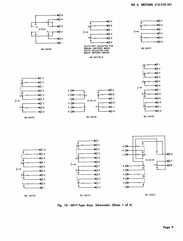
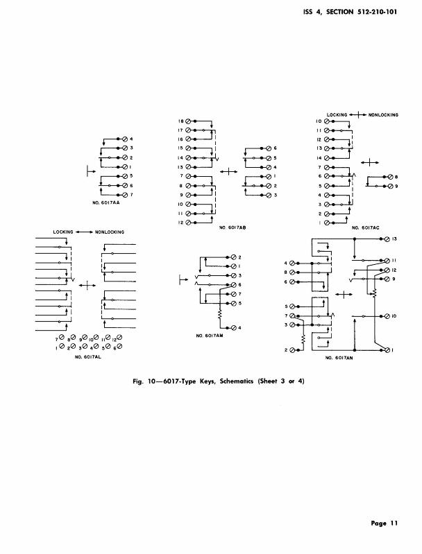
Fig. 10-6017-Type Lever Keys, Schematics
Fig. 11-6026-Type Lever Keys, Schematics
Fig. 12-KS-21254 Type Keys, Schematics
Fig. 13-KS-21776 Type Keys, Schematics

ISS 4, SECTION S12-210-101
ORDERING GUIDE 6011-AND 6026-TYPE KEYS
KEY (SEE NOTE) PRINCIPLE USE KEY (SEE NOTE) PRINCIPLE USE
6017At Station Switching 6017Y 1A Key Private Line Circu it
6017Bt 2-Line Pickup 6017AA Station Signal - Key Equip-
6017Ct Station Ringing Key ment 102A
6017Dt 4-Wire Private Line Systems 6017AB
6017E 3-Line Pickup 6017AC General
6017AK 6017G Switching Key Used in No. 6017AL*
750A or 755A PBX
6017Ht Signal Control- 2-Wire 6017AM 5A Key Equipment Line- Station and Control
6017AN 5B Key Equipment Circuit
601 7Jt Line Cutoff in 1A and 1A1 Data Applicatio n - 4-Wire
Key Telephone Systems 6017AP Line - Equipped with 14A 6017AR guard-stamped LINE and
6017K 5A Key Equipment With 100- TEST at front and rear lever Type Loudspeaker positions, respectively.
6017L 5B Key Equipment With 100- 602GB 4A Key Equipment with Hold Type Loudspeaker
6026C 4-Wire Private Line Termination
6017M Loudspeaker and Paging Systems 6026D 4A Key Equipment (without 6017P hold , may be used w ith l A, ! AI ,
6017R 750A or 755A PBX Control or 1 A2 Key Telephone System)
6017S 6017T 2A Key Telephone Systems 6017U
• Contacts must be wired to terminal as required. See Fig. 3.
t (A&M Only).
Note: Early 6017- and current 6026-type keys are furnished in a black metal housing with a black handle but are available with red or white handle when specified on order. Current 6017-type key are furnished with a gray plastic cover and gray handle.
Page 5

SE<:TION 5 12-210-101
HABLE B .
ORDERING GUIDE KS-21776 TYPE KEYS
KEY LEVER POSITION
KEY CODE FUNCTION UP CENTER DOWN
REPLACES REPLACES !NOTES 1 AND 2) 16017-TYPE} I KS-21254 TYPE)
KS·21 776Ll 2PDT On None On 60178 • List 2 KS·21776L2 2PTT On Off On 6017A* List 1 K& 21776L3 2PDT On None Ont 6017C* List 3 K&21 776L4 4PTT On On On - -KS·21776L5 4PDT On None On 60170*,
List 4 H,• & J• KS·21776L6 4PTT On Off On - -K&21776L7 4PDT On None Ont - -KS·21776L8 4PTT Ont Off Ont - -KS·21776L9 4PTT On orr Ont - -
• (A&M Only).
t Indicates a momentary or non locking position.
Note 1. Key cov.,rs must be ordered separately as follows: Cover, K&21776L101 with color suffix added. Black (·03), 1vory (·50 ), Green (·51), Red (·53), Yellow (·56), White (·58), Light Beige (·60), or Light Gray (·61).
Note 2. The base o f all KS-21 776 type may be black or the same color ns the key cover.
Fig. 7 - KS-21776 Type Key
Page 6

ISS 4, SECTION 512-210-101
Fig. 8 - KS-21776 Type Key With Flexible Wiring Strip
Page 7

SECTION 5 12-210-101
Page 8
COVER
MOUNTING SCREWS
I<EY BASE
0 ---- COVER LOCKING NUT
Fig. 9 - KS-2 1776 Type Key With Screw Terminals
. AUXILIA RY MOUNTING BRACKET
d-+- fi:: 9 ~;
NO. 6017A
.--- --o0 3
''------<o09
NO. 60170
,-------<o(2)10
r1 -------<o0 9
I 1 ,r---~o0e
..) t.__' __ ~:: I-- LI___ __ oe> ~4 J _ o0
:' , '--- ----<-03
'--~---o02
'-----o0 •
NO . 60 17H
: t I I I '
"t f-
,J : t I I
: l t
' o03
Vf :~ f-
,J :: ' t 1106
6017B KEY ADJUSTED FOR BREAK · BEFORE - MAKE 6017K ADJUS TED FOR MAKE · BEFORE · BREAK
NO. 6017B,K
NO. 6017E
o0 1
' :: 10
o04 II
' :: :: 6
~0o
o0 9 4 0o
: :~ 3 0o
' 2 Q)o
o0 12 I 0o
NO. 6017J
Fig. 10- 6017-Type Keys, Schematics (Sheet 1 of 4)
ISS 4, SECTION 512-210-10 1
' 1103
t ' =~ f-1 :: t o06
NO. 6017C
NO . 6017G
12
t I I I
f I I
NO. 6 0 17L
Page 9

SECTION 512-210-101
(2)9
08
l o07
La: r- ' IQ)3
t 1 =~ NO. 6017M
,.-----1(2) 1
t :: f- .----oe>:
1 ' oe>~ '-----1(2)6
N0. 6017P
4 n.. ~
n.. ~
13 n..
: 15
16
: 17
18
Page 10
NO. 60175
I l ;J ~
--.: I ~
: ' "' I I -~
': ~ ' "' _,.,.
J T -+- ~
l l _,.,. ' t: : t
I I
_11 ~ I
~ I t -~
"'
NO. 6017R
7
14
12
II
10
9
6
5
9
LOCKING -+-- NONLOCK ING
KS-8108 BUZZER FOR 6017T KS-8109 BUZZER FOR 6017U
NO . 6017T , U, W (MOl
NO. 6017Y
LOCKING ~ NONLOCKING
·~ ~1 7
5~· 5 16 10 I 15
11(2Jo I
~I 14
12~y-l--13 ::
I
~= ' l ii ' :7
I 6
3 cZ----t t e018
NO. &OITAK
Fig. 10-6017-Type Keys, Schematics (Sheet 2 of 4)
NO. 6017AA
LOCKING +-+ NONLOCKING
70 a0 901o0 110 120
1 0 20 30 40 s0 s0
NO. 6017AL
ISS 4, SECTION 512-210-101
18~ 17~ 16 e-.---J I
I 15~1 14~
13 e.---J -+-:~ 9 0-.--J1
I I 0 e-.--, 1
I I e---o---i.J 120----J
NO. 6017AB
NO. 6017AM
Fig. 10-6017-Type Keys, Schematics (Sheet 3 or 4)
LOCKING -+-- NONLOCKING
10~ I I 0+--o---'-,
12~: 13 0+--<>---T 14 co----l -+-:~ r---+0& 5 ~: .i....-..-0 9
:~ 2~ 10--J
NO. 6017AC
NO. 6017AN
Page 11

SECTION 512-2 10-101
6
13
14
15
10
II
12
~ 1 R4
:::: ~
:~R2
'<.J
,.,.
""'~RI
l
R3
~
r: I
~ : t
f t --i
1 l t: t
I ll Rl, R2 ·600ll
t R3, R4 - 5 to n R5-120ll
NO. 6017AP R5
:::: ~
0
~
17
18
16
4
9
13
14
15
16
10
II
12
n.
n. ~
~ "" ,.,. ~
R2 J '<.J
~
T I I
+ I t
T-i l
1 l t : l
I I I
j_l Rl - 130 0
t R2 -1 300 R3 - 1260ll
110. 6017 AR
Fig . 10- 6017-Type Keys, Schematics (Sheet 4 of 4 )
Page 12
"n. ,.,.
/>. ~
~
"n.
R3
17
18

+
: t I
~ I 2 15A ~ ~
JACK u
361C r ~ "" lJ I
I I I
237A JACK
v ~
t
I I
~
6026A
~ 6
J'>.
f>o
0
'"" ... C' ~
3B VAR ISTOR
0
n.
n.
10
n. ~
~:: 60 26C
ISS 4, SECTION 512-210-101
OFF
TALK t POSIT ION
HOLD
r L
il__
Jr-lc-I 215A ~ l::
JACK u
361C r ~ "" lJ I
I I I
2 15A JACK
60268
0
n. ~
10
n. ~
~
A c: 38
VARIS TOR
0
0 2
L-------~----------~~--~ 10
60 260
38 VARISTOR
Fig . 11 - 6026-Type Keys, Schematic
Page 13/ 14


ISS 4, SECTION 512-210-101
2A:J 2At 2At 2A:J 2At 2C 2C o-- 2C:J 2C 2C:J 28 o--1 28 o--1 28 28 o--1 28
4A:J 4At 4At 4A:J 4At 4C 4Co-- 4C:J 4C 4C:J 48 o--1 48o--1 48 48 o--1 48
UP CENTER DOWN UP DOWNt
t LIST 3, NONLOCKING POSITION LIST 1 LIST 2 AND 3
1A:J 1At 1C 1C:J 18 o--1 18
2A:J 2At 2C 2C:J 28 o--1 28
3A:J 3At 3C 3C:J 38 o--1 38
4A:J 4At 4C 4C:J 48 o--1 48
UP DOWN
LIST 4
Fig. 12-KS-21254 Type Keys (MD). Schematic
Page 15

SECTION S 12-210-101
1. ~:J 1. 1. ~:J ::J ::J 2<>-3,_1 3,_1 3,_1
4. ::J 4. 4. ::J ::J ::J 5<>-
so--1 so--1 so--1 UP OOWNt UP CENTER DOWN
t LIST 3, NONLOCKING POSITION LIST 1 AND 3 LIST 2
1. ~:J 1. 1t ~:J ::J ::J 2<>-3,_1 3,_1 3,_1 4. ::J 4. 4t ::J ::J ::J
5o--so--1 so--1 so--1
7t ::J 7. 7. ::J ::J ::J 8<>-
so--1 so--1 so--1 10t 10:1 10t 10. 10:J 11 :J 11 11:J 11 o-- 11 12 12,__1 12 12,__1 12J
UP DOWN t UP t CENTER DOWN t,
t LIST 5, NONLOCKING POSITION t LIST 8, NONLOCKING POSITION LIST 5 AND 7 t LIST 9, NONLOCKING POSITION LIST 6, 8, AND 9
Fig. 13-KS-21776 Type Keys, Schematics (Sheet 1 of 2)
Page 16

ISS 4 , SECTION 512-210-101
0 0 0 @) STRAPS
OUTPUT 1
OUTPUT 2
CENTER
~- -~ ® ® 12 OUTPUT 2
-~ ~- INPUT 2
® ® ®
OUTPUT 3
DOWN INPUT 1--t---"
LIST 4 (SEE NOTE 2)
NOTES :
1. LIST 4 ~AY BE CONVERTED TO A TWO POLE SWITCH WITH EACH POLE HAVING ONE INPUT ANO THREE OUTPUTS BY ADDING TWO STRAPS AS SHOWN .
2. LIST 4 ~AY BE CONVERTED TO A TWO POLE DOUBL E THROW "AKE-BEFORE-BREAK SWITCH BY THE ADDITION OF TWO STRAPS AS SHOWN . TERMINALS 6 & 9 ARE NOT USED .
Fig . 13 - KS-21776 Type Keys, Schematics (Sheet 2 of 2)
Page 17 17 Pages