bench work in wood
TRANSCRIPT
BENCH WORK IN WOOD
A COURSE OF
STUDY AND PRACTICE
FOR THE USE OF SCHOOLS AND COLLEGES,
W. F. M. GOSS,PROFESSOR OF PRACTICAL MECHANICS, PURDUE UNIVERSITY,
LAFAYETTE, INDIANA.
BOSTON:PUBLISHED BY GINN & COMPANY.
1888.

Entered according to Act of Congress, in the year 1887, by
W. F. M. GOSS,
in the Office of the Librarian of Congress, at Washington.
TYPOGRAPHY BY J. S. GUSHING & Co., BOSTON.
PRESSWORK BY GINN & Co., BOSTON.

rr
PREF
STATE NORMAL SCH90L
MANUAL AT A*D HUME 6CNiMICS
LCE:SANTA BAH&AIIA, CALIFORNIA
avoid confusion, the subject herein treated is con-
sidered in three divisions. Part I. contains the essen-
tial facts concerning common bench tools for wood;
it
describes their action, explains their adjustments, and shows
how they may be kept in order. Part II. presents a course
of practice by which ability to use the tools may be ac-
quired ;and Part III. discusses such forms and adaptations
of joints as will meet the requirements of ordinary construc-
tion. It is not expected that the student will complete Part
I. before entering upon Part II., or that he will finish Part
II. before commencing Part III. He will find greater profit
in using them together. For example, a shop exercise involv-
ing the chisel (Part II.) should be accompanied or preceded
by a study of the chisel (Part I.) ; again, the various forms
of mortise and tenon joints (Part III.) will be better under-
stood and more easily remembered, if considered during the
time when types of such joints are under construction in the
shops (Part II.). In the writer's experience with classes of
^students, one hour has been given to class-room work for every
^'
five hours given to shop work. By this apportionment, Parts
I. and III. can be mastered in the class-room while Part II.
is in progress in the shops.
The equipment necessary for carrying out the course of

IV PREFACE.
practice given in Part II. is much less expensive than may at
first appear. Besides a bench, a pair of trestles, and a bench-
hook, the following-named tools are needed :
2-ft. Rule.
Framing-Square .
7-inch Try-Square.
8-inch Bevel.
8-inch Marking-Gauges.
Chalk-Line, with Chalk.
Lead-Pencil.
Scriber.
Firmer-Chisels, i each, \", \",
I", i", |, f", i", and i".
Gouges, i each, f", j, |", and
i".
i 22-inch Cross-cutting-Saw, 8
teeth.
pair 8-inch Dividers.
pair jj-mch Matching-Planes.
T\-inch Beading-Plane.
\-inch Beading-Plane.
Plow.
i 24-inch Ripping-Saw, 6 teeth.
i lo-inch Back-Saw.
i 8-inch Drawing-Knife.i Fore-Plane.
i Jack- Plane.
i Smooth-Plane.
i Set Auger-Bits, J" to i" byi6ths.
i Bit-Brace,
i Brad-Awl,
i Carpenter's Hammer,i Mallet,
i Nail-Set,
i Oilstone.
i Hand-Scraper.- doz. Quill Bits, assorted from \"
down.
i Miter-Box.
i Grindstone.
if provision is to be made for more than one student, the
items printed in small type need not be duplicated. One set
of these will suffice for any number less than thirty.
The writer is indebted to Mr. M. Golden, of the School
of Mechanics and Engineering, Purdue University, for the exe-
cution of many of the drawings and for valuable suggestions.
W. F. M. G.
PURDUE UNIVERSITY,
Lafayette, Ind.
CONTENTS.
INTRODUCTION. INTERPRETATION OFMECHANICAL DRAWINGS.
PAGES
I . Mechanical Drawings Defined. 2. Plans. 3. Elevations.
4. Method of showing Parts Obscured from Sight. 5. Sections.
Section Lines. Cross-hatching. Incomplete Sections. 6. Bro-
ken Drawings. 7. Scale. 8. Dimensions. Dimension Lines, 1-6
PART I. BENCH TOOLS.
9. Bench. 10. Bench-Stop. 1 1. Vise. 12. Bench-Hook.
13. Trestles . . .;. -9
MEASURING AND LINING APPLIANCES.
14. Early Standards of Length. 15. English Standard Yard. 16.
United States Standard of Length. 17. The Troughton Scale.
18. Rules. 19. Framing-Square. 20. Board-measure Table.
21. Brace-measure Table. 22. Try-Square. 23. Bevel.
24. "Miter-Square." 25. Try-and-" Miter "Square. 26. Di-
viders. 27. Scribing with Dividers. 28. Combining Squareand Rule. 29. Combining Square and Bevel. 30. Setting
the Bevel at an Angle of 60 Degrees. 31. Setting the Bevel at
any Given Angle. 32. Marking-Gauge. 33. Mortise-Gauge.
34. Panel-Gauge. 35. Cutting-Gauge. 36. Chalk-Line.
37. Scriber. 38. Pencil 9-20
v- CONTENTS.
PAGES
CHISELS AND CHISEL-LIKE TOOLS.
39 . Firmer.Chisels.-40. Framing-Chisels. -41- Corner-Chisels.-A 2 Gouges -43. Chisel Handles. 44- Drawmg-Kmfe. 45-
Action o* Cu,i Wedges. -46. Ang.e of Cutting Wedge in
ChM and Gouge. -47- Grinding. -48. Whettmg ...*-.
SAWS.
49. Efficiency. -50- Form.- 5 i. Set. - 52. Size of Teeth. -53-
Ripping-Saw and Cross-Cutting-Saw Defined.- 54- Teeth of
Ripping-Saws.-
55. Teeth of Cross-Cutting-Saws.-
56. Back-
Saw. 57. Compass-Saw2 3
APPLIANCES FOR FILING AND SETTING SAWS.
58.Files. 59. Sets for Bending the Tooth. 60. Sets for Swedging
the Tooth. 61. Clamps 36-38
SAW FILING AND SETTING.
62 Top-Jointing. 63. Setting. 64. Filing. 65. Side-Jointing, 39~4i
PLANES AND PLANE-LIKE TOOLS.
66. Description of Planes. 67. Length of Stock. 68. Plane-Iron.
Angle of Cutting Wedge. 69. Outline of Cutting Edge. 70.
Use of Different Bench Planes. 71. Action of Smooth-Plane
and Fore-Plane Compared. 72. The Cap. 73. Narrowness of
Mouth. 74. Adjusting the Iron. 75. Jointing a Plane. 76.
Iron Planes. 77. Planes of Wood and Iron Combined. 78.
Circular-Planes. 79. Block-Planes. 80. Spokeshaves. 8l.
Rabbeting-Planes. 82. Matching-Planes. 83. Hollows and
Rounds. 84. Beading-Planes. 85. Plows. 86. Combina-
tion Planes. 87. Scrapers 4 l~S 2
BORING TOOLS.
88. Augers. 89. Auger-Bits. 90. Sharpening Augers and Auger-
Bits. 91. Center-Bits. 92. Expansive Bits. 93. Small Bits.
94. Bit-Braces. 95. Angular Bit-Stock. 96. Automatic
Boring Tool 53-59

CONTENTS.
MISCELLANEOUS TOOLS.
97. Winding-Sticks. 98. Hand Screw-Driver. 99. Brace Screw-
Driver. 100. Hammer. 101. Hatchet. 102. Mallet.
103. Sand-Paper. 104. Wooden Miter-Box. 105. Iron
Miter-Box. 106. Clamps. 107. Grindstone. 108. Use of
Water on a Grindstone. 109. Truing a Grindstone. no.
Truing Devices for Grindstones. in. Oilstones. 112. Oil
for Oilstones. 113. Form of Oilstones. 114. Oilstone Slips.
115. Truing an Oilstone 59-^9
PART II. BENCH WORK.
1 1 6. Good Lines a Necessity. 1 1 7. Location of Points. 118.
Jointed Face. 119. Working-Face 7i~73
EXERCISE No. i. MEASURING AND LINING.
I2O. Material. 121. Spacing: Pencil and Rule. 122. Lining:
Pencil, and Framing-Square. 123. Chalk-Lining. 124. Lin-
ing: Pencil, and Try-Square. 125. Lining: Pencil and Bevel.
126. "Gauging" Lines: Pencil and Rule. 127. Spacing:
Scriber and Rule. 128. Lining: Scriber, and Try-Square.
129. Lining: Scriber and Bevel. 130. Gauge-Lining. 131.
Lining for Exercise No. 3 73~79
EXERCISE No. 2. CHISELING AND GOUGING.
132. Chiseling by Hand. 133. Chiseling by Use of Mallet. 134.
Gouging 80-83
EXERCISE No. 3. SAWING.
135. Handling the Saw. 136. Guiding the Saw. 137. Correct-
ing the Angle of the Cut. 138. Rip-Sawing. 139. Cross-
cutting 83-86
EXERCISE No. 4. PLANING.
140. Handling the Plane. 141. Why a Plane Clogs. 142. Joint-
ing. 143. Planing to a Square. 144. Method of Performing

vjiiCONTENTS.
PAGES
Similar Operations. 145. Smooth Surfaces. 146. Sand-
Papering86-S<
EXERCISE No. 5. Box.
147. Jointing to Width. 148. Sawing to Length. 149. Nailing.
150. Hammer Marks. 151. Setting Nails. 152. With-
drawing Nails. 153. Fastening the Box Bottom. Finishing
the Box. 154. Planing End Grain 91-96
EXERCISE No. 6. BENCH-HOOK.
155. Lining and Sawing. 156. Using the Auger-Bit .... 96-98
EXERCISE No. 7. HALVED SPLICE.
157. Lining. 158. Value of Working-Face Illustrated. 159. Cut-
ting the Joint. 160. Sawing a Fit. 161. Toeing Nails . 99-102
EXERCISE No. 8. SPLAYED SPLICE.
162. Lining. 163. Cutting and Finishing the Joint .... 103, 104
EXERCISE No. 9 SIMPLE MORTISE-AND-TENON JOINT.
164. Lining. 165. Cutting the Mortise. 166. Cutting the Tenon.
167. Making a Pin. 1 68. Drawhoring 104-110
EXERCISE No. 10. KEYED MORTISE-AND-TENON JOINT.
169. Lining and Cutting. 170. Key . . . .- no, in
EXERCISE No. n. PLAIN DOVETAIL.
171. Lining and Cutting. 1 72. Gluing. 173. Short Method of
Lining and Cutting the Joint 112,113
EXERCISE No. 12. LAP DOVETAIL.
174. Lining and Cutting 114,115

CONTENTS. IX
PAGES
EXERCISE No. 13. BLIND DOVETAIL.
175. Lining and Cutting. 176. A Modified Form of the Joint . 115-117
EXERCISE No. 14. FRAME AND PANEL.
177. Panel Door Described. 178. Making the Joint between Stile
and Rail. 179. Cutting Chamfers. 180. Keying the Joint.
181. Finishing the Panel. Fastening Panel to Frame.
182. Inserting Screws. 183. Using the Brad-Awl . . . 117-121
EXERCISE No. 15. FRAME AND PANEL
184. Making Joint between Stile and Rail. 185. Plowing. 186.
Beading. 187. Forming the Panel 121-124
PART III. ELEMENTS OF WOOD CON-
STRUCTION.
TIMBER.
188. Timber Defined. 189. Felling. 190. Seasoning. 191.
Shrinkage. 192. Swelling. 193. Warping. 194. Effect of
Shrinkage on Cross-section. 195. Effect of Shrinkage on
Length 124-129
CARPENTRY.
196. Work of Carpenter and Joiner Compared. 197. Compres-
sional, Tensional, and Cross-Strain Defined. 198. Effect of
Cross-Strain. Neutral Axis. Relation between the Depth of a
Timber nnri its Resistance to Cross-Strain. 109. Rankine's
Principles concerning Joints and Fastenings .... 130-132
X CONTENTS.
PAGES
JOINTS CONNECTING TIMBERS IN THE DIRECTION OF THEIR LENGTH.
200. Lapped Joint. 201. Fished Joint. 202. Scarfed Joints.
203. Scarfed Joint for Resisting Compression. 204. Scarfed
Joint for Resisting Tension. 205. Scarfed Joint for Resisting
Cross-Strain. 206. Scarfed Joint for Resisting Tension and
Compression. 207. Scarfed Joint for Resisting Tension and
Cross-Strain '33-135
JOINTS CONNECTING TIMBERS AT RIGHT ANGLES.
208. Halving. 209. Notching. 210. Cogging. 211. Mortise-
and-Tenon Joints. 212. Mortise and Tenon Joining a Vertical
to a Horizontal Timber. 213. Mortise and Tenon Joininga Horizontal to a Vertical Timber. 214. Mortise and Tenon
Joining One Horizontal Timber to Another. Tusk Tenon 136-139
MISCELLANEOUS JOINTS.
215. Oblique Mortise and Tenon. 216. Bridle-Joint. 217. Tie-
Joint. 218. Chase-Mortise 139-141
JOINERY.
219. Joinery Described141, 142
BEADS AND MOLDINGS.
220. Beads. 221. Use of Beads. 222. Chamfer. 223. StopChamfer. 224. Moldings Described. 225. Round Nose.226. Some Typical Forms of Moldings. Fillet. 227. Jointsin Joinery Defined
142-145
HEADING-JOINTS, OR JOINTS UNITING PIECES IN THE DIRECTION OFTHEIR LENGTH.
228. Square Heading-Joint. Splayed Heading-Joint 145
CONTENTS. XI
PAGES
JOINTS UNITING PIECES IN THE DIRECTION OF THEIR WIDTH.
229. Their Office. 230. Butt-joint. Filleted Joint. Rabbeted
Joint. Matched Joint. 231. Glued Butt-joint. 232. Cleat-
ing. 233. Side Cleats. 234. End Cleats. 235. Relieving
Cleats from Strain .............. 145-148
JOINTS UNITING PIECES AT RIGHT ANGLES.
236. Butt-joint. 237. Miter-Joint. 238. Strengthening of Miter-
Joints. 239. Dovetail-Joints. 240. Proportions of Mortise-
and-Tenon Joints. 241. Single and Double Tenons. 242.
Haunching. 243. Four Tenons. 244. Mortises and Tenons
at an Angle in the Work. 245. Modifications of Mortise-and-
Tenon Joints ............... 148-152
PANELING.
246. Panel. 247. Frame. 248. Joints between Panel and
Frame .................. 152-155
FASTENINGS.
249. Pins. 250. Wedges. 251. Blind-Wedging. 252. Keys.
253. Dowels. 254. Nails. 255. Size of Nails. 256.
Brads. 257. Tacks. 258. Screws. 259. Glue . . . 15


INTRODUCTION.
EMS.
INTERPRETATION OF MECHANICAL DRAWINGS.
i. Most of the illustrations presented with the following
chapters are in the form of Mechanical Drawings. To the
novice, these may appear confusing ;but careful attention to
some of the principles underlying their con-
struction will enable him readily to interpret
their meaning.A mechanical drawing, as distinguished from
a perspective drawing, or picture, instead of
giving all the characteristics of an object at a
glance, presents them in detail, giving in one
view one set of elements, in another view another set of
elements, and so on, until the form of the ob-
ject is accurately defined.
For example, Fig. i is a perspective view
of an object which is represented mechanically
by Fig. 2. By Fig. i it will at once be seen
that the object represented is a cylinder. In
Fig. 2 there is first presented a plan, showingthat the object is cylindrical ; and, secondly,
an elevation, showing the height of the cylinder.
From the combination of these two views, the
solid may be as easily imagined as from Fig. i,
and the knowledge obtained of it is much more
definite.
A perspective view of an object is that whichELEVATION.
is had by looking from some one point, as A, Fig. 3, while a
view represented by a mechanical drawing supposes the ob-

BENCH WORK IN WOOD.
server to be looking from an infinite number of points, and
always in parallel lines, as indicated by A, Fig. 4.
2. A Plan of any object
represents it as it would
appear if, standing on its
natural base, it were looked
down upon vertically, as
indicated by the arrows A,
Fig. 5. If the object, as a rectangular block, has no fixed
base, any one of its faces may be taken as such.
3. An Elevation of any object represents it as it would
appear if, standing on its natural base, it were looked upon in a
p,.^ Q horizontal direction, as indicated byarrows B, Fig. 5.
The elevation is always at right
angles to the plan. There may be
several elevations of the same object,
each differing from the others as the
point of observation changes. For
example, the plan and elevation of the object rep-
resented by Fig. 6, are usually made as shown by
Fig. 7, but they may be made as shown by Fig. 8 or
Fig. 9.
ELEVATION.
FACE B.
INTRODUCTION.
Fig. 8 Fig. 9
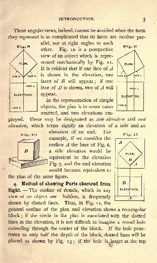
These angular views, indeed, cannot be avoided when the form
they represent is so complicated that its faces are neither par-
allel, nor at right angles to each
other. Fig. 10 is a perspective
view of an object which is repre-
sented mechanically by Fig. u.
It is evident that if one face ofAis shown in the elevation, two
faces of B will appear ;if one
face of B is shown, two of A will
appear.
In the representation of simple
objects, the plan is in some cases
omitted, and two elevations em-
ployed. These may be designated as side elevation and end
elevation, which terms signify an elevation of a side and an
elevation of an end. For
example, if we consider the
surface A the base of Fig. 6,
a side elevation would be
equivalent to the elevation
Fig. 7, and the end elevation
would become equivalent to
the plan of the same figure.
4. Method of showing Parts obscured from
Sight. The outline of details, which in anyview of an object are hidden, is frequently
shown by dotted lines. Thus, in Fig. 12, the
general outline of the plan and elevation shows a rectangular
block;
if the circle in the plan is associated with the dotted
lines in the elevation, it is not difficult to imagine a round hole
extending through the center of the block. If the hole pene-trates to only half the depth of the block, dotted lines will be
placed as shown by Fig. 13; if the hole is larger at the top
BENCH WORK IN WOOD.
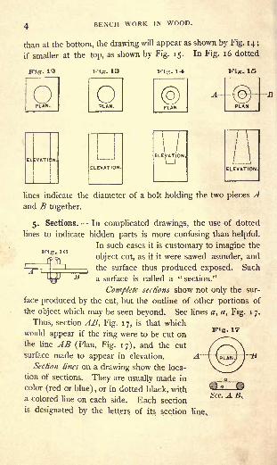
than at the bottom, the drawing will appear as shown by Fig. 14 ;
if smaller at the top, as shown by Fig. 15. In Fig. 16 dotted
Fig- Fig. 13 Kig. 14 Kig. 15
Kig. 10
lines indicate the diameter of a bolt holding the two pieces Aand B together.
5. Sections. In complicated drawings, the use of dotted
lines to indicate hidden parts is more confusing than helpful.
In such cases it is customary to imagine the
object cut, as if it were sawed asunder, and
"A i K'
^tne SUI ace tnus produced exposed. Such
^J ^ a surface is called a " section."
Complete sections show not only the sur-
face produced by the cut, but the outline of other portions of
the object which may be seen beyond. See lines #, a, Fig. 17.
Thus, section AB, Fig. 17, is that which
would appear if the ring were to be cut onthe line AB (Plan, Fig. 17), and the cut
surface made to appear in elevation.
Section lines on a drawing show the loca-
tion of sections. They are usually made in
color (red or blue), or in dotted black, with
a colored line on each side. Each section
is designated by the letters of its section line,
FUg. 17
Sec. A B,
INTRODUCTION.
Fig. 10
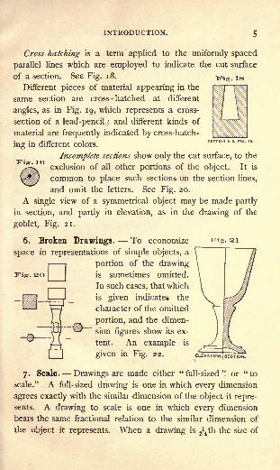
Cross-hatching is a term applied to the uniformly spaced
parallel lines which are employed to indicate the cut surface
of a section. See Fig. 18.
Different pieces of material appearing in the
same section are cross-hatched at different
angles, as in Fig. 19, which represents a cross-
section of a lead-pencil ;and different kinds of
material are frequently indicated by cross-hatch-
ing in different colors.
Incomplete sections show only the cut surface, to the
exclusion of all other portions of the object. It is
common to place such sections on the section lines,
and omit the letters. See Fig. 20.
A single view of a symmetrical object may be made partly
in section, and partly in elevation, as in the drawing of the
goblet, Fig. 21.
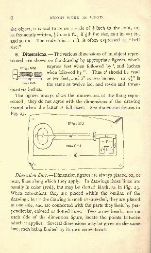
6. Broken Drawings. To economize
space in representations of simple objects, a
portion of the drawingis sometimes omitted.
In such cases, that which
is given indicates the
character of the omitted
portion, and the dimen-
sion figures show its ex-
tent. An example is
given in Fig. 22.
7. Scale. Drawings are made either "full-sized" or "to
scale." A full-sized drawing is one in which every dimension
agrees exactly with the similar dimension of the object it repre-
sents. A drawing to scale is one in which every dimension
bears the same fractional relation to the similar dimension of
the object it represents. When a drawing is ^th the size of
Fig. 21
Fig. SO
BENCH WORK IN WOOD.
the object, it is said to be on a scale of \ inch to the foot, or,
as frequently written, | in, = i ft.;
if th the size, as 2 in. = i tt.,
and so on. The scale 6 in. = i ft. is often expressed as " half
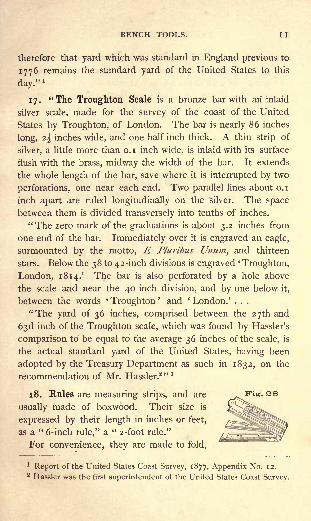
8. Dimensions. The various dimensions of an object repre-
sented are shown on the drawing by appropriate figures, which
33 express feet when followed by ',and inches
when followed by ". Thus 2' should be read
as two feet, and 2" as two inches. 12' 7f" is
HALF SIZE.tne same as twelve feet and seven and three-
quarters inches.
The figures always show the dimensions of the thing repre-
sented; they do not agree with the dimensions of the drawing
except when the latter is full-sized. See dimension figures in
Fig. 23. ^__ __r
Fig. 23
Dimension lines. Dimension figures are always placed on, or
near, lines along which they apply. In drawings these lines are
usually in color (red), but may be dotted black, as in Fig. 23.
When convenient, they are placed within the outline of the
drawing ; but if the drawing is small or crowded, they are placedat one side, and are connected with the parts they limit by per-
pendicular, colored or dotted lines. Two arrow-heads, one oneach side of the dimension figure, locate the points between
which it applies. Several dimensions may be given on the same
line, each being limited by its own arrow-heads.

PART I.
BENCH TOOLS.
g. Bench. A simple form of bench is shown by Fig. 24.
Its length A may vary from 6' upwards, according to the length
of work to be done. Its height B should also be regulated by
the character of the work high for light work, and low for
heavy as well as by the height of the person who is to use it.
Carpenters' benches are usually about 33" high, while those of
cabinet and pattern makers are from 2" to 4" higher.
- cEND ELEVATION. SIDE ELEVATION.
The surface of the bench, particularly of the thick plank that
forms the outer edge of it, should be perfectly flat a true
plane. When in use, care must be taken to protect it from
injury. It should never be scarred by the chisel or cut by the
saw. If oiled and shellaced, it is likely to be better kept.
10. The Bench-Stop a is intended to hold the work while
it is being planed. It may be simply a piece of wood about
2r'x 2", projecting through a mortise in the top of the bench
;

g BENCH WORK IN WOOD.
but it is far better to have some form of iron fitting, many of
which are supplied by the trade. The char-
acteristics of all of them are well illustrated
by the one shown in Fig. 25. The frame
A is let into the bench even with its sur-
face. The hook C is held in position at
any height above the bench by the action
of the screw B. C may be fastened even
with the surface of the bench, or removed
entirely.
ii. The Vise d, Fig. 24, is of a form that, for general pur-
poses, has long been in use. To hold the work well, the jaw d
should be as nearly as possible parallel to the face g, against
which it acts. If it is not parallel, the space between should
be less at the top than at the bot-
tom an arrangement which in-
sures a much better grip upon the
work than the opposite conditions.
Adjustments for parallelism are
made by changing the pin c from
one hole to another. There are
various mechanical appliances for
preserving automatically the paral-
lelism of this vise, but none are in common use. Iron vises can
be had which are adapted to the same uses as the one just
described; they maintain their parallelism, and are easier and
more perfect in action.
An iron bench vise, such as is shown by Fig. 26, is extremelyuseful for small work, and, if expense is not to be considered,
should supplement the vise d, in which case it may be located
on the bench at H.
The holes, e, in the bench are for the reception of a plug,which may be used to support one end of a long piece of workwhile the other end is held by the vise.

BENCH TOOLS. 9
12. A Bench-Hook, Fig. 178, applied to the bench as
shown by Fig. 167, provides a stop to prevent work from
sliding across the bench. The flat faces which rest on the
bench and receive the work, should be true planes and par-
allel. A length of from 14" to 16" is convenient, though
bench-workers frequently have several of different lengths.
13. Trestles, or "horses," are used in various ways to sup-
port material, and also Fi<r 27to take the place of the ' - *'
bench when large pieces
of material are to be
operated upon. A con-
venient form is shown
by Fig. 27.
MEASURING AND LINING APPLIANCES.
14. Early Standards of Length. To meet the earliest
need of units of measure, it was natural to adopt the means
nearest at hand, and common consent, no doubt, brought into
use the pace, the forearm, or cubit, the foot, the hand, the nail,
etc. These were certainly convenient enough, for wherever he
might go, every individual carried his units of measure with him.
Variations in their length, however, were inevitable, and manyattempts were made to reduce them to a standard. An old
English statute, the substance of which has descended to
American arithmetics of modern date, enacts " that three
barleycorns, round and dry, make an inch, twelve inches make
a foot, three feet a yard, etc.;and there seems to be no doubt
that this mode of obtaining a standard was actually resorted to.
But setting aside the objection due to the varying size of the
individual grains, unless the average of a large number be
taken, it is so difficult to know how much of the sharp end
of a grain of barley must be removed to make it'
round,' that

IO BENCH WORK IN WOOD.
the definition is not of much value. Nevertheless, in spite
of numerous attempts at legislation on the subject, this, down
to the year 1824, was the only process by which the standard
yard of this country [England] could, if lost, be legally re-
covered."1
Previous to the institution of a national standard of length
in Great Britain, influential men and prominent societies pro-
vided themselves with so-called standards, which were accepted
and used in different localities. By comparison with many of
these, the present standard of length was made, and its length
defined by law as the British standard yard. From this, about
fifty copies have been made. Two of these copies were in 1855
sent to the United States, and have since been in the keeping
of the Coast Survey. They are described as follows :
15." Each standard of length is a solid bar 38 inches long
and i inch square, in transverse section. One inch from each
extremity a cylindrical well, one-half inch in diameter, is sunk
one-half inch below the surface. At the bottom of the wells,
in each bar, is a gold pin about o.i inch in diameter, uponwhich are drawn three transversal and two longitudinal lines.
The wells are protected by metal caps. The length of one
English yard at a specified temperature is defined by the dis-
tance from the middle transversal line in one well to the middle
transversal line in the other, using the parts of those lines which
are midway between the longitudinal lines."2
16. The United States Standard of Length." The stand-
ard yard of Great Britain was lawful in the colonies before
1776. By the Constitution of the United States the Congressis charged with fixing the standard of weights and measures,but no such enactment has ever been made by Congress, and
1
Shelley's"Workshop Appliances."
2Report of the United States Coast Survey, 1877, Appendix No. 12.
BENCH TOOLS. -
1 1
therefore that yard which was standard in England previous to
1776 remains the standard yard of the United States to this
day."1
17. "The Troughton Scale is a bronze bar with an inlaid
silver scale, made for the survey of the coast of the United
States by Troughton, of London. The bar is nearly 86 inches
long, 2^- inches wide, and one- half inch thick. A thin strip of
silver, a little more than o.i inch wide, is inlaid with its surface
flush with the brass, midway the width of the bar. It extends
the whole length of the bar, save where it is interrupted by two
perforations, one near each end. Two parallel lines about o.i
inch apart are ruled longitudinally on the silver. The space
between them is divided transversely into tenths of inches.
"The zero mark of the graduations is about 3.2 inches from
one end of the bar. Immediately over it is engraved an eagle,
surmounted by the motto, E Pluribus Unum, and thirteen
stars. Below the 38 to 42-inch divisions is engraved'
Troughton,
London, 1814.' The bar is also perforated by a hole above
the scale and near the 4O-inch division, and by one below it,
between the words '
Troughton' and ' London.' . . .
"The yard of 36 inches, comprised between the 27th and
63d inch of the Troughton scale, which was found by Hassler's
comparison to' be equal to the average 36 inches of the scale, is
the actual standard yard of the United States, having been
adopted by the Treasury Department as such in 1832, on the
recommendation of Mr. Hassler. 2 " 1
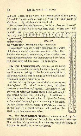
18. Rules are measuring strips, and are
usually made of boxwood. Their size is
expressed by their length in inches or feet,
as a " 6-inch rule," a " 2-foot rule."
For convenience, they are made to fold,
1Report of the United States Coast Survey, 1877, Appendix No. 12.
2 Hassler was the first superintendent of the United States Coast Survey.
12 BENCH WORK IN WOOD.
and one is said to be " two-fold" when made of two pieces,
" four-fold" when made of four, and "six-fold
" when made of
six pieces. Fig. 28 shows a four-fold rule.
To preserve the rule from wear, the better class are "bound "
by a strip of brass which covers each edge ;others are "half-
bound," hav-' A ! iV > '*
' '* ' W '
Vo ''
Idf '
Ig'
'
I7 ^I6 i
'-Id I
'
liM-Ma (2"IF:
in* only one to::^^edge covered ;
and still othersEIS . so
are "unbound," having no edge protection.
Carpenters' rules are usually graduated to eighths
of inches on one side, and to sixteenths on the other.
Besides the regular graduations, other numbers are
frequently represented ;but their purpose is so varied
that their interpretation cannot be given here.
19. The Framing-Square, Fig. 29, as its name
implies, is intended primarily for use in framing, and
would seem to belong to the builder rather than to
the bench-worker;but its range of usefulness makes
it valuable to any worker in wood.
All but the very cheapest are of steel, and many are
nickel-plated. The nickel prevents rust, and gives
clearness to the lines and figures. The figures of the
graduations along the several edges, begin at the angleand extend to the ends of the legs. In addition to
these, there is on one side a line of figures beginningat the end of the long leg and extending to the angle.
On the reverse side, represented by Fig. 29, there is
on the long leg a board-measure table, and on the
short leg a brace-measure table.
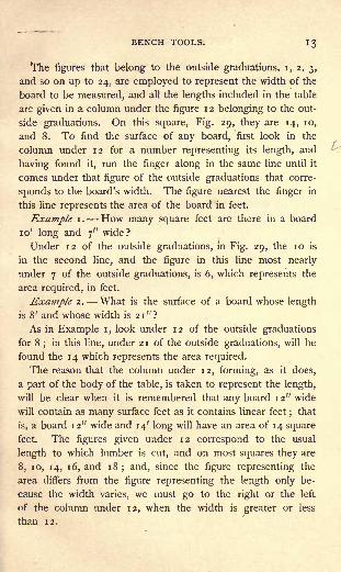
20. The Board-measure Table. Lumber is . sold by the
square foot, and the value of the table lies in its giving the areaof a board, or of any surface, in square feet, when its length in
feet and its breadth in inches are known.
BENCH TOOLS. 13
The figures that belong to the outside graduations, i, 2, 3,
and so on up to 24, are employed to represent the width of the
board to be measured, and all the lengths included in the table
are given in a column under the figure 1 2 belonging to the out-
side graduations. On this square, Fig. 29, they are 14, 10,
and 8. To find the surface of any board, first look in the
column under 12 for a number representing its length, and
having found it, run the finger along in the same line until it
comes under that figure of the outside graduations that corre-
sponds to the board's width. The figure nearest the finger in
this line represents the area of the board in feet.
Example i . How many square feet are there in a board
10' long and 7" wide?
Under 12 of the outside graduations, in Fig. 29, the 10 is
in the second line, and the figure in this line most nearly
under 7 of the outside graduations, is 6, which represents the
area required, in feet.
Example 2. What is the surface of a board whose length
is 8' and whose width is 21"?
As in Example i, look under 12 of the outside graduations
for 8;
in this line, under 2 1 of the outside graduations, will be
found the 14 which represents the area required.
The reason that the column under 12, forming, as it does,
a part of the body of the table, is taken to represent the length,
will be clear when it is remembered that any board 12" wide
will contain as many surface feet as it contains linear feet ;that
is, a board 12" wide and 14' long will have an area of 14 square
feet. The figures given under 12 correspond to the usual
length to which lumber is cut, and on most squares they are
8, 10, 14, 16, and 18; and, since the figure representing the
area differs from the figure representing the length only be-
cause the width varies, we must go to the right or the left
of the column under 12, when the width is greater or less
than 12.
BENCH WORK IN WOOD.
Fig. 30
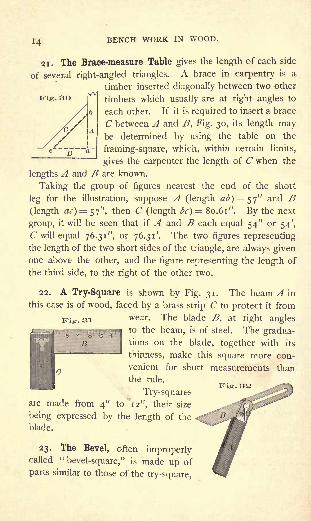
21. The Brace-measure Table gives the length of each side
of several right-angled triangles. A brace in carpentry is a
timber inserted diagonally between two other
timbers which usually are at right angles to
each other. If it is required to insert a brace
C between A and B, Fig. 30, its length maybe determined by using the table on the
framing-square, which, within certain limits,
gives the carpenter the length of C when the
lengths A and B are known.
Taking the group of figures nearest the end of the short
leg for the illustration, suppose A (length at>)=$'j" and B(length ac) = 57", then C (length bc} = 80.61". By the next
group, it will be seen that if A and B each equal 54" or 54',
C will equal 76.31", or 76.31'. The two figures representing
the length of the two short sides of the triangle, are always givenone above the other, and the figure representing the length of
the third side, to the right of the other two.
22. A Try-Square is shown by Fig. 31. The beam A in
this case is of wood, faced by a brass strip C to protect it from
Vie. si wear - Tne Wade>
at right anglesto the beam, is of steel. The gradua-tions on the blade, together with its
thinness, make this square more con-
venient for short measurements than
the rule.
Try-squaresare made from 4" to 12", their size
being expressed by the length of the <
blade.
23. The Bevel, often improperlycalled "bevel-square," is made up of
parts similar to those of the try-square, 1

BENCH TOOLS.
Fig. 33
as will be seen by Fig. 32. The blade is adjustable to any
angle with the beam;
the thumb-screw C fastens it when
set.
The size of a bevel is expressed by the length of its beam in
inches.
24. ''Miter-Squares" derive their
name from the purpose they are in-
tended to serve. A "miter" in con-
struction is one-half of a right angle,
or an angle of 45 degrees. In the"miter-square
"the blade, as in the
try-square, is permanently set, but
at an angle of 45 degrees, as shown
by Fig. 33.
The bevel, while neither so con-
venient nor so accurate, is often
made to answer the purpose of the "miter-square."
25. A Combination Try-and-" Miter"
Square is shown by Fig. 34. This, while
KiS . 34 Rperfect as a try-
_ :r .___ }* square, is trans-
formed into a "mi-
ter-square" when
the face of the
beam AB is placed
against the work-
ing-face (119) of the material.
26. Dividers are much used in spacing
and in laying off circles and arcs of circles.
The form shown by Fig. 35 is known as "arc and set-screw
dividers." The two points are held at any desired distance
from each other by the action of the set-screw A upon the
arc B. In setting, the final adjustment may be made more

i6 BENCH WORK IN WOOD.
Fig. 36
delicate by use of the thumb-nut C, which, acting in opposi-
tion to the spring D, shortens the arc B or allows the spring to
lengthen it, as may be required.
27. Scribing with Dividers: Example i. The four legs
of a table are of unequal length, and prevent it from standing
even. Scribe the legs to length.
First, by means of blocks or wedges under the shorter legs,
make the top of the table to stand parallel to some plane sur-
face, as a bench top, or even the floor if
it is in good condition, either of which
may be designated as F, Fig. 36. Set
the dividers equal to or greater than the
height of the thickest blocking, so that
while one point, a, touches the leg, the
other, b, will rest upon F in the same vertical line. Move the
dividers, keeping b on F, and producing by a a line on the leg, as
ca, which, if the dividers are properly handled, will be parallel
to the surface F. Without changing the dividers, mark at least
two adjoining faces on each leg, and cut the legs to line.
It is evident that lines thus scribed will all be at an equal
distance from the surfa.ce F; .and the table top, having been
. 37 made parallel to F, it
follows that the lines
scribed are parallel to
the top, or that the
length of the four legs,
as defined by the lines,
is the same.
Example 2. It is required to fit the end of a board B to
the outline abed of A, Fig. 37. Place the board in the position
shown, and set the dividers at a distance equal to x. Withone point at a and the other at e, let them be moved together,one following the outline abed which the other produces on B,
BENCH TOOLS. I?
as shown. Cut to line, and the board will fit. When sharp
angles, as at /, enter into the outline, greater accuracy will
be attained if the point / is located by measuring from the
base line hi.
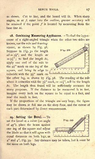
28. Combining Measuring Appliances. To find the hypot-
enuse of a right-angled triangle when the other two sides are
known, use the rule and framing-
square, as shown by Fig. 38.
Suppose in Fig. 30 the length
ab = 5^", and the length ac
= 9^" ;to find the length be,
apply one end of the rule to .^^^ E-3
the 9^" mark on one leg of the
square, and bring its edge to /"ot 6 s * 9 s *
-J , V 1 If SS. f,tl. l'.'l,ft'l.lfl,l?l.l,
tl, , ?!,,?!, 1*1, I ?!.,'.*l. l.'l.l'-
comcide with the 5^ mark on
the other leg, as shown by Fig. 38. The reading of the rule
where it coincides with the 5^" mark, or 10^", will be the length
be. The length thus found will be sufficiently accurate for
many purposes. If the distance to be measured is in feet,
imagine every inch on the square to be equal to a foot, and
read the result in feet.
If the proportions of the triangle are very large, the figure
may be drawn at full size on the shop floor, and the extent of
each part determined by direct measurement.
29. Setting the Bevel. Toset the bevel at a miter (an angle
of 45), place the beam against
one leg of the square and adjust
the blade so that it will agree with
equal distances on both legs, as
4" and 4", Fig. 39. Any distance may be taken, but it must be
the same on both legs.

BENCH WORK IN WOOD.
Fig. 40
The carpenter frequently describes an angle to which the
bevel may be set, as"
i in 2"or "
i in 4," by which is meant
that while the beam is applied, as shown by Fig. 39, the blade
corresponds to the i" mark on one leg, and the 2" mark on
the other; or to the i" mark on one leg, and the 4" mark on
the other.
30. To set the Bevel at an Angle of 60 Degrees. In
Fig. 40 the board A has a jointed edge a;from this, square the
line be. With any radius,
use the dividers to strike
the arc be;
with the same
radius, strike from b the arc
Place the beam of the
bevel against the working-
face a, move the blade till
it coincides with the points
b and /, and the bevel is set at an angle of 60 degrees with one
side of the beam, and 120 degrees with the other.
31. To set the Bevel at any given Angle. If an attemptis made to set the bevel di-
rectly from lines on paper, it
will be found difficult to de-
termine when the tool agrees
with the parts of the drawing.It is better, therefore, to
transfer such an angle to a
board, from the working-edgeof which the bevel may be
set. Thus, if it is required to
set the bevel at the angle
abc, Fig. 41, a board as A,should be lined as follows :
from the working-edge gauge the line a'V with the dividers,
Fig. 41

BENCH TOOLS. 19
at any convenient radius, describe from b' the arc e'd';with the
same radius describe from b the arc ed;set the dividers so that
with one point on e the other will fall on/, and lay off this dis-
tance on e'J', locating /' ;connect b' and /' ;
the angle a'b'c'
will be equal to abc. As a'b' is by construction parallel to the
working-edge of the board, the angle between the working- \/edge and b'c' is equal to the angle abc. If, then, with the beam
of the bevel on the working-edge, the blade is made to coin-
cide with b'c', the bevel will be set at the angle abc.
32. Marking-Gauges. Fig. 42 shows the usual form of a
marking-gauge. The steel point, or "spur," <?,should be filed
to a narrow edge, so that it
will make a sharp line.
The graduations along the m^ r
length of the beam B, are
not to be depended on un-
less it is known that the
zero line is exactly opposite
the spur. When the zero mark and the spur do not agree, as
is frequently the case, it is necessary in setting the gauge to
measure from the head A to the spur e. A when set, is pre-
vented from moving on B, by the screw C.
33. A Mortise-Gauge, shown by Fig. 43, has two spurs, a
being fastened to the beam, and b to a brass slide which works
in a groove in the beam. The
spur b may be set at any dis-
tance from a by the action of
the screw c. The gauge may,
therefore, be set to line both
sides of a mortise at the same time.
34. Panel-Gauges, Fig. 44, are for use in making lines at a
considerable distance from the working-edge.
20 BENCH WORK IN WOOD.
The length of the head A is sufficiently increased to receive
good support from the working-edge, which guides it.
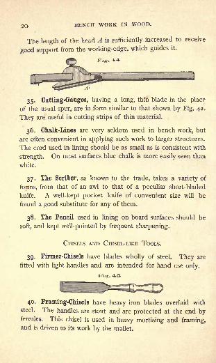
35. Cutting-Gauges, having a long, thin blade in the place
of the usual spur, are in form similar to that shown by Fig. 42.
They are useful in cutting strips of thin material.
36. Chalk-Lines are very seldom used in bench work, but
are often convenient in applying such work to larger structures.
The cord used in lining should be as small as is consistent with
strength. On most surfaces blue chalk is more easily seen than
white.
37. The Scriber, as known to the trade, takes a variety of
forms, from that of an awl to that of a peculiar short-bladed
knife. A well-kept pocket knife of convenient size will be
found a good substitute for any of them.
38. The Pencil used in lining on board surfaces should be
soft, and kept well-pointed by frequent sharpening.
CHISELS AND CHISEL-LIKE TOOLS.
39. Firmer-Chisels have blades wholly of steel. They are
fitted with light handles and are intended for hand use only.
Kig.45
40. Framing-Chisels have heavy iron blades overlaid with
steel. The handles are stout and are protected at the end byferrules. This chisel is used in heavy mortising and framing,and is driven to its work by the mallet.

BENCH TOOLS. 21
Compare Fig. 45, which shows a firmer-chisel, with Fig. 46,
which shows a framing-chisel.
Fig. 4=0
The size of chisels is indicated by the width of the cutting
edge, and varies frojn"
to i" by sixteenths, and from i" to
2" by fourths.
41. A Corner-Chisel is shown by Fig. 47. Its two cutting
edges are at right angles to each other, and this form renders
it useful in making inside angles, as, for example, the corners of
a mortise. Its handle is like that of a framing-chisel. The lize
of a corner-chisel is indicated by the length of one cutting edge.
42. Gouges have blades that, throughout their length, are
curved in section, as shown by Fig. 48. When the bevel forming
Fig. 48
the cutting edge is on the concave side, they are called "inside
gouges"
;when on the convex side,
" outside gouges." For
general purposes the outside gouge is most convenient, and the
carpenter, with his limited facilities for the care of tools, can
more easily keep it in order. The size of a gouge is indicated
by the length of a straight line extending from one extremity of
the cutting edge to the other.
22 BENCH WORK IN WOOD.
43. Handles for chisels, gouges, and similar tools, are of two
general classes, light and heavy ;the former are intended prin-
cipally for hand use, and are shown in connection with the firmer-
chisel and gouge ;the latter, which are re-enforced at the end
by a ferrule that they may withstand blows from the mallet, are
illustrated in connection with the framing-chisel and the corner-
chisel.
Handles may be shank-fitted, like the one shown oy Fig. 48,
or socket-fitted, as shown by Fig. 47. The better class of tools
have socket-fitted handles.
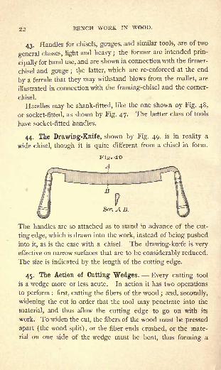
44. The Drawing-Knife, shown by Fig. 49, is in reality a
wide chisel, though it is quite different from a chisel in form.
The handles are so attached as to stand in advance of the cut-
ting edge, which is drawn into the work, instead of being pushedinto it, as is the case with a chisel. The drawing-knife is very
effective on narrow surfaces that are to be considerably reduced.
The size is indicated by the length of the cutting edge.
45. The Action of Cutting Wedges. Every cutting tool
is a wedge more or less acute. In action it has two operations
to perform : first, cutting the fibers of the wood; and, secondly,
widening the cut in order that the tool may penetrate into the
material, and thus allow the cutting edge to go on with its
work. To widen the cut, the fibers of the wood must be pressed
apart (the wood split), or the fiber ends crushed, or the mate-
rial on one side of the wedge must be bent, thus forming a

BENCH TOOLS. 23
shaving. It is evident that a unit of force tending to drive the
edge forward will, under like conditions of material, always
result in the same amount of incision. But much less force is
required to carry the tool forward when the cutting edge is just
entering the material, than when it has advanced to a consider-
able depth, and, hence, it is fair to assume that this difference is
due solely to the resistance that the material offers in opening
to make way for the tool, this resistance increasing as the tool
goes deeper. The resistance offered to a tool by a bending
shaving, therefore, may be many times greater than that offered
to the cutting edge by the wood fibers.
An obtuse-angled wedge will cut as easily as a more acute-
angled one, but the more obtuse the angle is, the more abrupt
must be the turning of the shaving ;and since the latter factor
is the more important, as regards the absorption of force, it
follows that the more acute the cutting edge is, the more easily
it will accomplish its work.
46. Angle of Cutting Wedge in Chisel and Gouge. The
acuteness of the angle cannot be defined in degrees since,
being limited only by the strength of the steel, it must vary as
the duty required of it varies. For example, a more acute
angle may be used in soft than in hard wood; again, a chisel
handled as shown by Figs. 147 and 148, is not so severely
strained as when used in the manner illustrated by Fig. 149.
If the maximum degree of delicacy were insisted on under
every condition of use, the cutting edge would need to vary
with every turn of the chisel, and almost with every shaving it
cuts. This would be impracticable, and wood workers reduce
all these requirements to a single principle which may be
expressed as follows : let the cutting edge be as acute as the
metal will allow without breaking, when fairly used. A little
experience with a given tool is the readiest means of finding
the angle suited to a given class of work. Carriage makers,

24 BENCH WORK IN WOOD.
who work almost wholly in hard woods, are in the habit of
using what pattern makers, who work principally in soft woods,
would style blunt chisels.
47. Grinding. A new chisel, or one that has become con-
siderably dull, must be ground. With the handle of the chisel
in the right hand, and the fingers of the left hand resting on
the blade near its cutting edge, apply the chisel to the stone,
Fig. 50, as shown by the dotted outline a, and then raise the
right hand until the proper angle is reached, a position indi-
cated by the full outline b. See that there is a good supply of
water, and, as the grinding progresses, move the tool gradually
from one side of the stone to the other.
Assuming that the stone is in fairly good order, the tool
should be applied relative to its motion, in the manner shown
by a and b, Fig. 50, the motion being in the direction of the
arrow d. If the stone is not round or does not run true, there
is danger that the cutting edge may dig into it, to the injury of
both stone and tool. Under such conditions, it will be best for
the operator to move round to the other side, and hold the tool
in the position indicated by c. The first position is preferable,
chiefly because of two reasons : first, the tool may be held
more steadily ; and, secondly, there is less tendency toward the
production of a " wire edge." As the extreme edge becomesthin by grinding, it springs slightly away from the stone, andallows the chisel at points still farther from the edge to become
thin, thus resulting in an extremely delicate edge which must be
removed before the tool can be made sharp. In the effort to
remove thij wire edge, itfrequently breaks off farther back than
BENCH TOOLS. 25
is desired, and the process of whetting is prolonged. With the
chisel held at c (instead of b, the proper position) the direc-
tion of the motion relative to the tool aggravates this tendencyof the light edge to spring away from the stone.
The grinding process is complete when the ground surface
reaches the cutting edge a condition readily determined by
holding the tool to the light. If it is still dull, there will be a
bright line along the cutting edge. When this line has disap-
peared, the tool is as sharp as it can be made by grinding,
which, if persisted in, will only result in a wire edge. The
action of the grindstone, however, is too severe to produce a
good cutting edge, and the chisel, after being ground, must be
whetted (107-110).
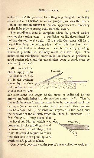
48. To whet the
chisel, apply it to
the oilstone A, Fig.
51, in the position
shown by the dot-
ted outline b, and
as it is moved back
and forth along the length of the stone, as indicated by the
arrows, gradually bring it to the position shown by l>'. That is,
the angle between it and the stone is to be increased until the
cutting edge c comes in contact with the stone;
this position
can be recognized by the sensation imparted to the hand, and
the behavior of the oil with which the stone is lubricated. At
first thought, it may seem that
the bevel ab, Fig. 52, which was Cvx mg . oa
produced by the grinding, should ^"S^!
^be maintained in whetting; but ^^_^ :
- fto do this would require so much N
\T>i
time that one corresponding very
nearly to ab, as cd, is taken.
Great care is necessary on the part of one unskilled to avoid giv-
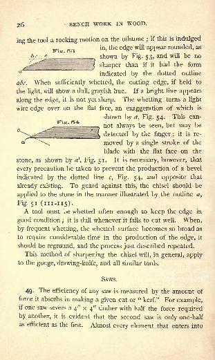
26 BENCH WORK IN WOOD.
ing the tool a rocking motion on the oilstone ;if this is indulged
^.^ ^ in, the edge will appear rounded, as
l>/ c shown by Fig. 53, and will be no
^-^ j sharper than if it had the form
indicated by the dotted outline
abc. When sufficiently whetted, the cutting edge, if held to
the light, will show a dull, grayish hue. If a bright line appears
along the edge, it is not yet sharp. The whetting turns a light
wire edge over on the flat face, an exaggeration of which is
shown by a, Fig. 54. This can-
not always be seen, but may be
_^ detected by the finger ;it is re-
ft moved by a single stroke of the
blade with the flat face on the
stone, as shown by a', Fig. 51. It is necessary, however, that
every precaution be taken to prevent the production of a bevel
indicated by the dotted line c, Fig. 54, and opposite that
already existing. To guard against this, the chisel should be
applied to the stone in the manner illustrated by the outline a,
Fig. 51 (111-115).A tool must be whetted often enough to keep the edge in
good condition;
it is dull whenever it fails to cut well. When,
by frequent whetting, the whetted surface becomes so broad as
to require considerable time in the production of the edge, it
should be reground, and the process just described repeated.
This method of sharpening the chisel will, in general, applyto the gouge, drawing-knife, and all similar tools.
SAWS.
49. The efficiency of any saw is measured by the amount of
force it absorbs in making a given cut or " kerf." For example,if one saw severs a 4" x 4" timber with half the force required
by another, it is evident that the second saw is only one-half
as efficient as the first. Almost every element that enters into

BENCH TOOLS. 2/
saw construction has its effect on the efficiency of the tool.
Chief among them is the thickness of the blade, which, of
course, determines the width of the kerf; for a wide kerf will
require the removal of more material than a narrow one, and
the force absorbed in each case must bear some relation to the
amount* of material removed. In recognition of this fact, the
people of some eastern countries use saws designed to cut
when drawn towards the operator, a method of handling that
allows great thinness of blade too great to stand the thrust bywhich our saws are driven into the work. But the result is
that the Chinese saw, for example, Fig . 55which is represented by Fig. 55,
accomplishes its work with re-
markable ease. The shape of such a saw, however, and the
awkward manner of applying force to it, probably more than
neutralize the advantage gained from its delicacy, although in
the abstract, the thinner the blade the better the saw.
50. The form of our own saws is not the result of chance,
but, on the contrary, has been developed after a careful study
of the conditions under which they are required to work.
Other things being equal, pushing a saw gives better results
than pulling it. Under a thrusting force, it is found necessary
to make the blade sufficiently thick and strong to resist bend-
ing tendencies, but with no surplus material to add unneces-
sary weight. In view of these facts the outline of the blade is
tapered, as shown by Fig. 56. The blade is thicker also at the
handle than at the point. To assist in giving it clearance in
the kerf, it is tapered from the teeth to the back. This differ-
ence in thickness is accomplished .in the process of manufacture,
28 BENCH WORK IN WOOD.
by grinding the rough blade after it has been hardened. Im-
perfections left by the hardening or the grinding process, maybe detected in the finished saw by bending the blade, as shown
by Fig. 57. If it is uniformly ground and hardened, the curve
will be regular as shown;
if it is thick in spots, or if it varies in
hardness, the curve will be uneven, as indicated by the dotted
line.
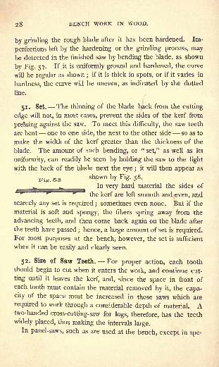
51. Set. The thinning of the blade back from the cutting
edge will not, in most cases, prevent the sides of the kerf from
pressing against the saw. To meet this difficulty, the saw teeth
are bent one to one side, the next to the other side so as to
make the width of the kerf greater than the thickness of the
blade. The amount of such bending, or "set," as well as its
uniformity, can readily be seen by holding the saw to the light
with the back of the blade next the eye ;it will then appear as
shown by Fig. 58.
In very hard material the sides of
the kerf are left smooth and even, and
scarcely any set is required ;sometimes even none. But if the
material is soft and spongy, the fibers spring away from the
advancing teeth, and then come back again on the blade after
the teeth have passed ; hence, a large amount of set is required.For most purposes at the bench, however, the set is sufficient
when it can be easily and clearly seen.
52. Size of Saw Teeth. For proper action, each tooth
should begin to cut when it enters the work, and continue cut-
ting until it leaves the kerf, and, since the space in front of
each tooth must contain the material removed by it, the capa-
city of the space must be increased in those saws which are
required to work through a considerable depth of material. Atwo-handed cross-cutting-saw for logs, therefore, has the teeth
widely placed, thus making the intervals large.In panel-saws, such as are used at the bench, except in spe-

BENCH TOOLS. 29
cial cases, the space is of the same size and form with the
tooth. When the spaces are large, the teeth must be large,
and, since the size of the spaces has a direct relation to the
amount of material removed, it may be said that the size of
the teeth depends on the size of the material in which the saw
is to work.
The size of saw teeth is expressed by the number contained
in an inch. Thus " 6 teeth" means that the distance from
one point to another is ".
53. Ripping-Saws and Cross-cutting-Saws. A ripping-saw
is one that is used in cutting with the grain of the wood, as on the
line ab, Fig. 59. Across-cutting-saw
is intended for use at right angles to
the grain, as indicated by cd, Fig.
59. An oblique kerf, such as is
shown by ef, Fig. 59, may in soft
wood be cut with the ripping-saw, which will work faster than
the cross-cutting, but the work will be more smoothly done
by the latter. A large knot in the course of the ripping-saw
may make it best to substitute the cross-cutting-saw until the
knot is passed through, after which the ripping-saw may be
used again. A cross-cutting-saw for the bench should have
Kij... GO
4.,
"-.
"Sec. A B.
ELEVATION.
a 22" or 24" blade with 7^ or 8 teeth to the inch; a rip-
ping-saw should have a 24" or 26 "
blade, with 6 or 6^ teeth.
30 BENCH WORK IN WOOD.
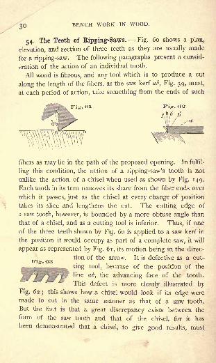
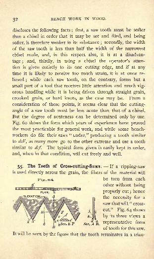
54. The Teeth of Ripping-Saws. Fig. 60 shows a plan,
elevation, and section of three teeth as they are usually made
for a ripping-saw. The following paragraphs present a consid-
eration of the action of an individual tooth.
All wood is fibrous, and any tool which is to produce a cut
along the length of the fibers, as the saw kerf ab, Fig. 59, must,
at each period of action, take something from the ends of such
Kiy. Gl Fig. OS
fibers as may lie in the path of the proposed opening. In fulfil-
ling this condition, the action of a ripping-saw's tooth is not
unlike the action of a chisel when used as shown by Fig. 149.
Each tooth in its turn removes its share from the fiber ends over
which it passes, just as the chisel at every change of position
takes its slice and lengthens the cut. The cutting edge of
a saw tooth, however, is bounded by a more obtuse angle than
that of a chisel, and as a cutting tool is inferior. Thus, if one
of the three teeth shown by Fig. 60 is applied to a saw kerf in
the position it would occupy as part of a complete saw, it will
appear as represented by Fig. 61, its motion being in the direc-
K-IO. OR ^on ^ tne arrow - It ig defective as a cut-
ting tool, because of the position of the
line ab, the advancing face of the tooth.
This defect is more clearly illustrated by
Fig. 62; this shows how a chisel would look if its edge were
made to cut in the same manner as that of a saw tooth.
But the fact is that a great discrepancy exists between the
form of the saw tooth and that of the chisel, for it has
been demonstrated that a chisel, to give good results, must

BENCH TOOLS. 31
be at least as acute as is indicated by the dotted line a;
and it would seem that the former might be improved by
bringing it more nearly to the outline of the latter. Sup-
pose this be attempted, and that the face of the tooth in-
dicated by the line cb, Fig. 60, be changed to cl>'. Such
a change must result either in removing material from the
tooth, and thereby weakening it, or in changing the line cd
to a position cd'. In other words, if the tooth is not weak-
ened, the space between it and the next will be reduced.
Again, if to make the advancing face still more acute, the line
cl>" is accepted, and the tooth is not made smaller (that is,
weakened), there will be no space between it and the next
tooth. Having no spaces, there can be no teeth, and conse-
quently the attempted change is impossible. It will thus be
seen that the angle of the advancing face of the ripping-saw
tooth cannot, unless it is weakened, be much more acute than
is shown by Fig. 60 and Fig. 61.
The form of the tooth may be wholly changed, however, to
the outline shown by Fig. 63, and some advantage may thus
be gained in respect of the cutting angle ;but such a tooth,
while suitable for machine-saws of considerable size, is too
complicated for small saws.
Nothing remains, then, as a possible means of improving the
cutting edge of the saw tooth, except a modification of the
angle bed, Fig. 60. If it could be shown that there is an excess
of strength in the tooth, above what is needed to perform its
work, the angle might be changed to b'cd, or even to b"cd, and
the value of the tooth as a cutting tool be increased. More-
over, it does not at first seem unreasonable to attempt such a
change, for it is evident that the cutting wedge of the chisel
(which we have regarded as the typical cutting tool), while
much more acute than the angle bed, is yet strong enough to
be entirely satisfactory.
A more careful comparison of the saw and chisel, however,
BENCH WORK IN WOOD.
discloses the following facts : first, a saw tooth must be softer
than a chisel in order that it may be set and filed, and being
softer, is therefore weaker in its substance; secondly, the width
of the saw tooth is less than half the width of the narrowest
chisel made, and, in this respect also, it is at a disadvan-
tage ; and, thirdly, in using a chisel the operator's atten-
tion is given entirely to its one cutting edge, and if at any
time it is likely to receive too much strain, it is at once re-
lieved;
while each saw tooth, on the contrary, forms but a
small part of a tool that receives little attention and much vig-
orous handling while it is being driven through straight grain,
crooked grain, or hard knots, as the case may be. From a
consideration of these points, it seems clear that the cutting-
angle of a saw tooth must be less acute than that of a chisel.
But the degree of acuteness can be determined only by use.
Fig. 60 shows the form which years of experience have provedthe most practicable for general work, and while some bench-
workers do file their saws "under," producing a tooth similar
to dcb\ as many more go to the other extreme and use a tooth
similar to dcf. The typical form given is easily kept in order,
and, when in that condition, will cut freely and well.
55. The Teeth of Cross-cutting-Saws. If a ripping-sawis used directly across the grain, the fibers of the material will
be torn from each
other without being
properly cut;hence
^e necessity f r a
saw that will"cross-
cut." Fig. 64 shows
by its three views a
rePresentative form
of tooth for this saw.
It will be seen by the figure that the tooth terminates in a trian-
Fis.64

BENCH TOOLS. 33
gular point ;and also, that while the point a is formed on one
side of the blade, the next, a', is formed on the opposite side;
thus throughout its length, the points of any two adjacent teeth
being on opposite sides of the blade. This arrangement makes
the end view of the blade show two parallel lines of points, and
between them a triangular depression, which, when exaggerated
by the "set," will appear as shown bysection AB, Fig. 64.
3ris '
In action, the points a and a', Fig. 65,
score the work, and the friction between
the teeth and the cut fibers breaks upthe latter, and they are carried off bythe saw.
Assuming that it is a matter of convenience to have these
teeth, as well as those of the ripping-saw, equal to the space
between any two of them, there are three questions which maybe considered concerning their proportions. First, what shall
be the inclination of the advancing edge or " face"
of the
tooth, as represented by the line ab compared with the line bd,
Fig. 64 ? Holly, in his little work on " The Art of Saw-Filing,"
shows the similarity of action between the advancing edge ab
and the edge of a pocket knife when made to cut across the
grain, and asserts that a knife with its cutting edge perpen-
dicular to the surface upon which it acts (a position equiva-
lent to bd} will make a rougher cut, and require more force
to carry it forward at a given depth, than when it is inclined
in a position similar to that of the line ab. The result obtained
from such an experiment cannot be regarded as conclusive,
because of the great difference in the character of the cutting
edges compared. But, if it is found that the knife with its
keen cutting edge behaves more satisfactorily at an inclination
to the work, it seems reasonable to conclude that the rougher
edge of a saw tooth will give the best results when much more
inclined. A consideration of these points justifies the belief

34 BENCH WORK IN WOOD.
that an angle of 60 degrees with the work, that is, with a line
passing through the points a ' and a, is none too great, and all
practice goes to show that teeth so formed not only do very
smooth work, but cut with ease and rapidity.
Secondly, what shall be the angle of the advancing face of
the tooth, as represented by lines e'e and ef, Sec. EF, Fig. 64 ?
Since this angle forms the cutting wedge of the tooth, it should
be as acute as is consistent with strength. Greater strength
being required for action in hard wood than in soft, it follows
that this angle should be varied with the material in which it is
used. For general work it may correspond to the angle e'ef.
Thirdly, what shall be the acuteness of the point as indicated
by the angle iaj, Sec. AB, Fig. 64 ? This, also, is determined
by the character of the material to be cut. It should be more
obtuse, as iak, for hard wood than for soft wood, not only be-
cause additional strength is required, but also because, if too
acute, the scoring will be done so easily that the fibers be-
tween the scores will not break out, and the saw, being unable
to pass down into new work, will slide along on the old.
Under such conditions, the bottom of the kerf will appearas shown by Fig. 66. A more obtuse angle will not pene-trate the work so readily, but it will break up the fibers better,and thus leave the kerf in proper form as shown by Fig. 67.The softer woods break out more easily than the harder ones,
and, consequently, a keener point may be used in working in
them.
56. The Back-Saw is used only where accurate cuts are
required. Its teeth, in form, are similar to those of the cross-
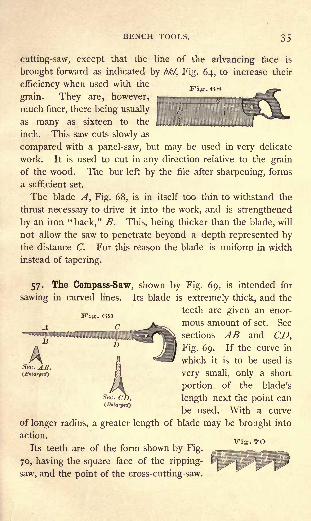
BENCH TOOLS. 35
Fig. G8
cutting-saw, except that die line of the advancing face is
brought forward as indicated by bkl, Fig. 64, to increase their
efficiency when used with the
grain. They are, however,
much finer, there being usually
as many as sixteen to the
inch. This saw cuts slowly as
compared with a panel-saw, but may be used in very delicate
work. It is used to cut in any direction relative to the grain
of the wood. The bur left by the file after sharpening, forms
a sufficient set.
The blade A, Fig. 68, is in itself too thin to withstand the
thrust necessary to drive it into the work, and is strengthened
by an iron "back," B. This, being thicker than the blade, will
not allow the saw to penetrate beyond a depth represented bythe distance C. For this reason the blade is uniform in width
instead of tapering.
57. The Compass-Saw, shown by Fig. 69, is intended for
sawing in curved lines. Its blade is extremely thick, and the
teeth are given an enor-
mous amount of set. See
sections AB and CD,
Fig. 69. If the curve in
which it is to be used is
very small, only a short
portion of the blade's
length next the point can
be used. With a curve
of longer radius, a greater length of blade may be brought into
action.
Its teeth are of the form shown by Fig.
70, having the square face of the ripping-
saw, and the point of the cross-cutting-saw.
Vis- GO
Sec. AR.(.Enlarged)
Fig. 70

, BENCH WORK IN WOOD.
They are thus adapted for use in any direction relative to the
grain of the wood.
APPLIANCES FOR SAW FILING AND SETTING.
58. A "Triangular Saw File
" l
is of the form shown by
Fig. 71. A "slim" saw file is represented by Fig. 72; it is
REGULAR.
two inches longer than a "regular" saw file of the
same cross-section. A " double ender "is shown by
Fig. 73, and a cross-section of all saw files, on an en-
larged scale, by Fig. 74.
59. Saw Sets. Fig. 75 shows a simple form of set.
The tooth to be bent is placed on the surface A, with
JFrequently called
"three-square saw file."

BENCH TOOLS. 37
Thus placed, the
Fig. 75
the adjacent teeth in contact with B, B.
blade is allowed to rest
on the screw C. A blow
from a hammer on Dbends or "sets" the tooth,
and a spring returns D to
the position shown. 1 The
amount of set is regulated
by the position of the
screw C, and is greater,
the lower C is fixed. If Cis raised to coincide with
the dotted line AE, the
tooth will not be set. B, B can be adjusted to the depth on
the tooth to which the set is to take effect.
60. Swedge Sets for Ripping-Saws, illustrated by Fig. 76,
are in general use on large
saws and, occasionally, on
small ones; generally speak-
ing, they do not concern the
bench-worker. The set
1 D is not well shown in the engraving. Since it must act on only one
tooth at a time, the end X is wedge-shaped.
38 BENCH WORK IN WOOD.
driven against the edge of the tooth, as shown by Fig. 77 ; by
using one opening the center of the tooth is forced back, as
at H; and by use of the other opening the points are spread,
completing the work, as at G. A tooth thus set is more
perfect in its action than when bent, since it cuts the full width
of the kerf.
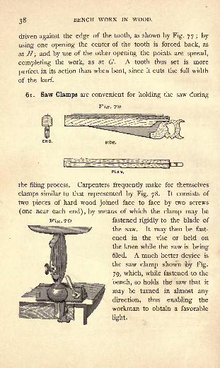
61. Saw Clamps are convenient for holding the saw during
Fig. 78
the filing process. Carpenters frequently make for themselves
clamps similar to that represented by Fig. 78. It consists of
two pieces of hard wood joined face to face by two screws
(one near each end), by means of which the clamp may be
. TO fastened rigidly to the blade of
the saw. It may then be fast-
ened in the vise or held on
the knee while the saw is being
filed. A much better device is
the saw clamp shown by Fig.
79, which, while fastened to the
bench, so holds the saw that it
may be turned in almost any
direction, thus enabling the
workman to obtain a favorable
light.
BENCH TOOLS. 39
To FILE AND SET A SAW.
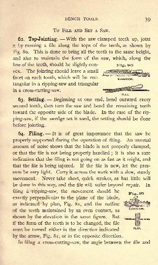
62. Top-Jointing. With the saw clamped teeth up, joint
it by running a file along the tops of the teeth, as shown by
Fig. 80. This is done to bring all the teeth to the same height,
and also to maintain the form of the saw, which, along the
line of the teeth, should be slightly con- yig. so
vex. The jointing should leave a small
facet on each tooth, which will be rec-
tangular in a ripping-saw and triangular
in a cross-cutting-saw.
63. Setting. Beginning at one end, bend outward every
second tooth, then turn the saw and bend the remaining teeth
toward the opposite side of the blade. In the case of the rip-
ping-saw, if the swedge set is used, the setting should be done
before jointing.
64. Filing. It is of great importance that the saw be
properly supported during the operation of filing. An unusual
amount of noise shows that the blade is not properly clamped,
or that the file is not being properly handled;
it is also a sure
indication that the filing is not going on as fast as it might, and
that the file is being injured. If the file is new, let the pres-
sure be very light. Carry it across the work with a slow, steady
movement. Never take short, quick strokes, as but little will
be done in this way, and the file will suffer beyond repair. In
filing a ripping-saw, the movement should be
exactly perpendicular to the plane of the blade,
as indicated by plan, Fig. 81, and the outline
of the teeth maintained by an even contact, as
shown by the elevation in the same figure. But
if the form of the teeth is to be changed, the file
must be turned either in the direction indicated PLAN>
by the arrow, Fig. 81, or in the opposite direction.
In filing a cross-cutting-saw, the angle between the file and

40 BENCH WORK IN WOOD.
the blade must be varied in accordance with the following con-
siderations : first, the outline of the teeth may be preserved
or changed in the manner just described in connection with
the ripping-saw; secondly, the angle of the advancing face
(e'ef, Fig. 64) is determined by the inclination of the file
to the blade, as shown
by the plan, Fig. 82;
thirdly, the angle of the
point (taj, Fig. 64) is
PLANT
. Fig. sa determined by the incli-
r~jnation of the file to the
AAA^^y^AA ^^\z^^^ blade, as shown by the
\ f/- ^3-^ii en<^ elevation, Fig. 82.
SIDE ELEVATION.END ELEVATION.
upon from principles already given, it may be produced without
difficulty by attending to the foregoing directions.
In filing any of the teeth herein discussed, the file should
always be in gentle contact with the face of one tooth, as b,
Fig. 8 1, while most of the cutting is done on the back of the
next one a, which, as usually considered, is the tooth that is
being filed. This tooth should be one which, by its set, bends
away from the operator. Beginning at one end of the blade,
he files every second tooth until the opposite end is reached,
when the blade is turned, and the remaining teeth filed from
the other side.
No saw, even though the teeth are not bent, should be filed
wholly from one side, for the file turns a slight edge, or bur;
and, since this increases the set, it should be evenly distributed
on both sides of the blade.
The filing on each tooth should continue until the facet
produced by the jointing disappears. After this is accom-
plished, a single stroke will make the tooth receiving it lower
than the others. To avoid this, it will be found best to leave
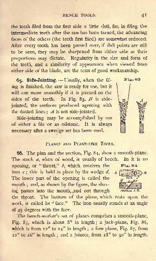
BENCH TOOLS. 4!
the teeth filed from the first side a little dull, for, in filing the
intermediate teeth after the saw has been turned, the advancing
faces of the others (the teeth first filed) are somewhat reduced.
After every tooth has been passed over, if dull points are still
to be seen, they may be sharpened from either side as their
proportions may dictate. Regularity in the size and form of
the teeth, and a similarity of appearance when viewed from
either side of the blade, are the tests of good workmanship.
65. Side-Jointing. Usually, when the fil- vig.&a
ing is finished, the saw is ready for use, but it 1/
will cut more smoothly if it is jointed on the '
sides of the teeth. In Fig. 83, B is side-
jointed, the surfaces produced agreeing with
the dotted lines;A is not side-jointed.
Side-jointing may be accomplished by use
of either a file or an oilstone. It is always
necessary after a swedge set has been used.
PLANES AND PLANE-LIKE TOOLS.
66. The plan and the section, Fig. 84, show a smooth-plane.
The stock a, when of wood, is usually of beech. In it is an
opening, or "throat," b, which receives the
iron c;
this is held in place by the wedge d.
The lower part of the opening is called the
mouth; and, as shown by the figure, the shav-
ing passes into the mouth, ^and out through section A B.
the throat. The bottom of the plane, which rests upon the
work, is called its" face." The iron usually stands at an angle
of 45 degrees with the face.
The bench-worker's set of planes comprises a smooth-plane,
Fig. 85, which is about 8" in length ;a jack-plane, Fig. 86,
which is from 12" to 14" in length ;a fore-plane, Fig. 87, from
22" to 26" in length ;and a jointer, from 28" to 30" in length.

BENCH WORK IN WOOD.
Similar purposes are served by the jointer and the fore-plane,
the former being unnecessary except for large surfaces that are
to be planed with accuracy.
Fig. 85
67. The Length of the Plane-Stock determines, in a measure,
the straightness of the work. Thus, a smooth-plane, if used on
Fig. ss an uneven surface, will,
as shown by Fig. 88, rise
over elevated portions and
settle in hollows, taking its shaving without interruption, and
producing no great change in the outline of the surface, while
a fore-plane or jointer
similarly applied will, as
shown by Fig. 89, cut
only on the higher parts,
and by so doing, produce an even surface.
The stock of a smooth-plane is made short so that, by its use,
a surface may be smoothed without incurring the necessity of
straightening it.
The fore-plane will smooth as well as the smooth-plane, but
not until it has first straightened the surface.
The jack-plane is used for cutting heavy shavings, and its
length bears no relation to the character of the work expectedof it, but is such as will enable the workman to grasp it easily
and firmly.
68. A "Plane-Iron" 1for a wooden plane is of iron overlaid
in part with steel. Ite cutting edge is maintained in precisely
the same way as that of a chisel. See 47 and 48. The angle
1 Known also as "plane-bit."
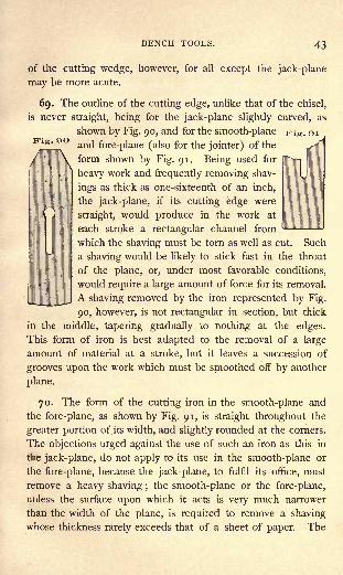
BENCH TOOLS. 43
of the cutting wedge, however, for all except the jack-plane
may be more acute.
69. The outline of the cutting edge, unlike that of the chisel,
is never straight, being for the jack-plane slightly curved, as
shown by Fig. 90, and for the smooth-plane prig. 91
and fore-plane (also for the jointer) of the
form shown by Fig. 91. Being used for
heavy work and frequently removing shav-
ings as thick as one-sixteenth of an inch,
the jack-plane, if its cutting edge were
straight, would produce in the work at
each stroke a rectangular channel from
which the shaving must be torn as well as cut. Such
a shaving would be likely to stick fast in the throat
of the plane, or, under most favorable conditions,
would require a large amount of force for its removal.
A shaving removed by the iron represented by Fig.
90, however, is not rectangular in section, but thick
in the middle, tapering gradually to nothing at the edges.
This form of iron is best adapted to the removal of a large
amount of material at a stroke, but it leaves a succession of
grooves upon the work which must be smoothed off by another
plane.
70. The form of the cutting iron in the smooth-plane and
the fore-plane, as shown by Fig. 91, is straight throughout the
greater portion of its width, and slightly rounded at the corners.
The objections urged against the use of such an iron as this in
tbe jack-plane, do not apply to its use in the smooth-plane or
the fore-plane, because the jack-plane, to fulfil its office, must
remove a heavy shaving ;the smooth-plane or the fore-plane,
unless the surface upon which it acts is very much narrower
than the width of the plane, is required to remove a shaving
whose thickness rarely exceeds that of a sheet of paper. The

44 BENCH WORK IN WOOD.
groove caused by the removal of so delicate a shaving, is suf-
ficiently blended with the general surface of the work, by the
rounded corners of the iron.
71. If a rough board is to be made smooth, or if a consider-
able amount of material is to be removed to bring a piece of
wood to size, most of the surplus stock should be taken off bythe jack-plane, after which the smooth-plane should be used to
give the surface desired. If the finished surface is to be straight
as well as smooth, the fore-plane should follow the jack-plane.
It is never necessary to follow the jack-plane with both the
smooth-plane and the fore-plane.
72. The Cap. A supplementary iron, or "cap," shown by
c, Fig. 92, is fastened to
most plane-irons. Its use
is well illustrated by the
two sections, Figs. 93 and
94. The single iron will
do smooth work as long as
the grain of the wood is favorable, as shown at a. When the
Kig. 02
grain becomes obstinate, as at b, the shaving, by running up on
the iron, acquires a leverage which causes it to split in advance
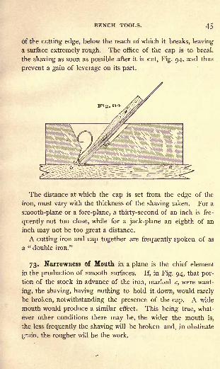
BENCH TOOLS. 45
of the cutting edge, below the reach of which it breaks, leaving
a surface extremely rough. The office of the cap is to break
the shaving as soon as possible after it is cut, Fig. 94, and thus
prevent a gain of leverage on its part.
The distance at which the cap is set from the edge of the
iron, must vary with the thickness of the shaving taken. For a
smooth-plane or a fore-plane, a thirty-second of an inch is fre-
quently not too close, while for a jack-plane an eighth of an
inch may not be too great a distance.
A cutting iron and cap together are frequently spoken of as
a " double iron."
73. Narrowness of Mouth in a plane is the chief element
in the production of smooth surfaces. If, in Fig. 94, that por-
tion of the stock in advance of the iron, marked c, were want-
ing, the shaving, having nothing to hold it down, would rarely
be broken, notwithstanding the presence of the cap. A wide
mouth would produce a similar effect. This being true, what-
ever other conditions there may be, the wider the mouth is,
the less frequently the shaving will be broken and, in obstinate
grain, the rougher will be the work.
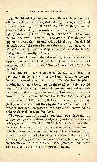
46 BENCH WORK IN WOOD.
74. To Adjust the Iron. To set the iron deeper, so that
a heavier cut may be taken, strike it a light blow, as indicated
by the arrow e, Fig. 84. If a lighter cut is required, strike the
stock as indicated by the arrow /. When the iron is in the
right position, a light blow will tighten the wedge. To remove
the iron and wedge, turn the plane over so that the face is
uppermost, grasp the iron and wedge with the right hand, hold
the back end of the plane between the thumb and finger of the
left, and strike the stock at / upon the surface of the bench.
A single blow is usually sufficient.
Never strike the plane while it is resting on the bench or any
support that is firm. It should be held in the hand clear of
everything ; but, if this is not convenient, one end may rest on
the knee.
To set the iron in a wooden plane, hold the stock in such a
way that, while the face rests on the hand, the end of the fore-
finger may extend across the mouth. Put the iron in place,
allowing its cutting edge to rest on the forefinger, which should
keep it from projecting. Insert the wedge, push it down with
the thumb, and by a light blow with the hammer drive the iron
down until its projection beyond the level of the face is equal
to the thickness of the shaving that the plane is to take;a sin-
gle tap on the wedge will then tighten the iron in place. The
distance that the iron projects, can easily be determined by
sighting along the face of the plane.
The wedge must not be driven too hard, for a plane may be
so distorted by a hard-driven wedge as to make it incapable of
doing good work. The iron will be held in place even when
the wedge is so loose that it may be drawn out with the fingers.
Notwithstanding the fact that wooden plane-stocks are made
from material little affected by atmospheric influences, they
will warp enough, especially when nearly new, to bring the face
considerably out of a true plane. When, from this cause, the
plane fails to do good work, it must be jointed.

BENCH TOOLS. 47
Fig. OS
75. To Joint a Plane, fasten it in a vise with the face upand the front end to the right. The iron should be in place, the
cutting edge well back within the mouth,
and the wedge driven as for work. It is now
necessary to determine whether the plane
to be jointed is twisted or not (97). Ap-
ply two parallel strips, or "winding-sticks,"
(the longer legs of two framing-squares will
answer), one across each end of the plane,
as indicated by Fig. 95. After makingsure that they are parallel, sight across one
to the other. As the eye is lowered, if the
one farther away is lost sight of all at the
same time, the plane is "out of wind," and
needs only to be straightened ; but, if one
end of the straight-edge that is farther
from the eye, disappears before its other
end, as in the elevation, Fig. 95, it is evident that the two
corners a and b, diagonally opposite, are high, and more must
be taken from them than from the other corners. With this
understanding, the fore-plane or the jointer may be applied
until the plane is jointed, that is, until the face is a true
plane.
During the planing process, frequent tests must be madewith the parallel strips, to make sure that the high corners
are being brought down properly. In the early stages of
the work, the try-square may be used occasionally to keepthe face as nearly as may be at right angles to one side,
and the straightness of the face may be determined either
by sighting or by use of the framing-square as a straight-
edge. A true face having been produced, the sharp angles
between it and the two sides should be changed to slight
chamfers, inasmuch as the sharp edges, if not removed, are
likely to splinter off.
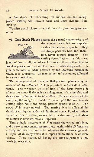
48 BENCH WORK IN WOOD.
A few drops of lubricating oil rubbed on the newly-
planed surface, will prevent wear and keep shavings from
sticking.
Wooden bench planes have had their day, and are going out
of use.
Iron Bench Planes possess the general characteristics of
the wooden ones, but are superior
to them in several respects. TheyE^"%X$\\. are alwavs perfectly true and, there-
fore, never require jointing. The
cutting"iron," which, in this case,
is not of iron at all, but of steel, is much thinner than that in
wooden planes, and is, therefore, more readily sharpened. Its
greater thinness is made possible by the thorough manner in
which it is supported. It may be set and accurately adjusted
in a very short time.
The arrangement of parts in Bailey's iron planes may be
understood by reference to Fig. 96, which represents a jack-
plane. The "wedge
" A is of iron of the form shown;
it
admits the screw E through an enlargement of a short slot, and
drops down, allowing E to take effect. By a movement of the
clamp S, the wedge A is made to press upon the iron near its
cutting edge, while the clamp presses against it at F, The
screw E is never moved. The cutting iron is adjusted for
depth of cut by the action of the thumb-screw D, which, when
turned in one direction, moves the iron downward, and when
its motion is reversed moves it upward.Thus a single movement of B releases the wedge and iron,
and a reverse movement secures them again, while D furnishes
a ready and positive means for adjusting the cutting edge with
a degree of delicacy which it is impossible to attain in wooden
planes. These planes, all having the same adjustments, are
made in every size.
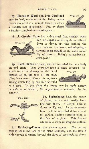
BENCH TOOLS. 49
77. Planes of Wood and Iron Combined
may be had, made up of the Bailey move-
ments mounted in a suitable frame, to which
a wooden face is fastened. Fig. 97 shows
a Stanley combination smooth-plane.
78. A Circular-Plane has a thin steel face, straight when
free, but capable of having its ends thrust
down or drawn up, thus making the
face concave or convex, and adapting it
to work on an outside or an inside curve.
Fig. 98 shows a Bailey's adjustable cir-
cular-plane.
79. Block-Planes are small, and are intended for use chiefly
on end grain. They generally have a single inverted iron,
which turns the shaving on the bevel irig . 90instead of on the face of the iron.
They have many different forms, from
among which Fig. 99 has been selected
as a type. In this plane the throat may be made narrow
or wide as is desired;
the adjustment is controlled by the
screw A.
80. Spokeshaves have the action
of planes, but are not usually classi-
fied with them. A simple form is
shown by Fig. 100. By the cross-sec-
tion it will be seen that it has almost
no guiding surface corresponding to
the face of a plane. This feature
adapts it to work of irregular outline.
81. Rabbeting-Planes have narrow stocks. The cutting
edge is set in the face of the plane obliquely, and the iron is
wide enough to extend beyond the sides of the stock, as shown

BENCH WORK IN WOOD.
Fig. 101
by Fig. 101. Rabbeting.-planes are designed for use in intenoi
angles, as Imk, Fig. 146. The oblique position of the iron
produces a shearing cut which pro-
motes smoothness in action.
The shaving of the rabbeting-plane
instead of passing through the stock is
turned in such a way as to be dis-
charged from one side;an arrange-
ment common to matching-planes, beading-planes, molding-
planes, and plows (2, 83, 84, and 85).
82. Matching-Planes are used to form a tongue and a
groove, as shown respectively by a and b, Fig. 102.
Wooden matching-planes, Fig. 102, are Vi ^ 102sold in pairs, one plane being fitted with a A
single cutting edge, to form the groove, the
other with a double cutting edge, to form the
tongue. Both are guided by the " fence"
j
C, which moves in contact with the working
face of the piece operated upon. Thec *-nj
groove and the tongue should both be car-
ried to as great a depth as the plane will
cut.
An iron matching-plane, designed to serve
the purpose of the two wooden ones, is now in general use.
Its fence is pivoted to the face in such a way that it can be
turned end for end; in one position two cutters are exposed
Fig. IDS and the plane is adjusted to form the tongue ;
Uwhen its position is reversed, the fence covers one
of the cutting edges, and puts the plane in shape*
for making the groove.
The size of matching-planes is indicated by the
thickness of the material they are intended to
V-v VJ match.
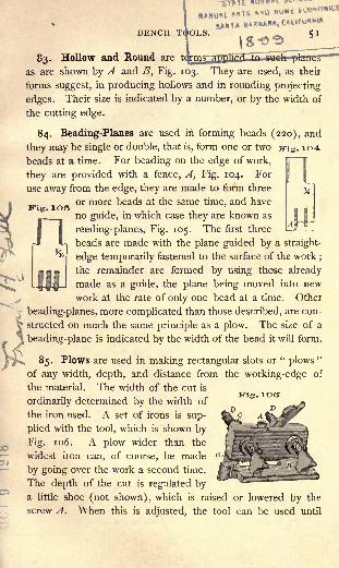
ftNUl
BENCH 51
\a-e>*
83. Hollow and Round are te
as are shown by A and B, Fig. 103. They are used, as their
forms suggest, in producing hollows and in rounding projecting
edges. Their size is indicated by a number, or by the width of
the cutting edge.
84. Beading-Planes are used in forming beads (220), and
they may be single or double, that is, form one or two iris . 104
beads at a time. For beading on the edge of work,
they are provided with a fence, A, Fig. 104. For
use away from the edge, they are made to form three
or more beads at the same time, and have*
no guide, in which case they are known as
reeding-planes, Fig. 105. The first three
r* U beads are made with the plane guided by a straight-
edge temporarily fastened to the surface of the work;
the remainder are formed by using those already
made as a guide, the plane being moved into new
work at the rate of only one bead at a time. Other
beading-planes, more complicated than those described, are con-
structed on much the same principle as a plow. The size of a
beading-plane is indicated by the width of the bead it will form.
85. Plows are used in making rectangular slots or "plows
"
of any width, depth, and distance from the working-edge of
the material. The width of the cut is
ordinarily determined by the width of
the iron used. A set of irons is sup-
plied with the tool, which is shown by
Fig. 1 06. A plow wider than the
widest iron can, of course, be made
by going over the work a second time.
The depth of the cut is regulated bya little shoe (not shown), which is raised or lowered by the
screw A. When this is adjusted, the tool can be used until
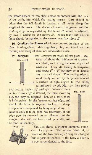
52 BENCH WORK IN WOOD.
the lower surface of the shoe comes in contact with the face
of the work, after which the cutting ceases. Care should be
taken that the full depth is reached at all points along the
length of the work. The distance between the groove and the
working-edge is regulated by the fence B, which is adjusted
by nuts C acting on the screws D. When ready for use, the
fence should be parallel to the narrow iron face-piece E.
86. Combination Planes which may be used in place of the
plow, beading-plane, rabbeting-plane, etc., are found on the
market, and many of them are serviceable tools.
87. Scrapers. Hand-scrapers are made of saw-plate ma-
-. IOT terial of about the thickness of a panel-
saw blade, and having the same degree of
hardness. They are usually rectangular,
and about 4" X 5", but may be of almost
any size and shape. The cutting edge is
most easily formed by the production of
a surface at right angles to the sides,
as indicated by af>, Fig. 107, thus giving
two cutting angles, cef and dfe. When a more
acute cutting edge is desired, the form shown by
Fig. 108 may be adopted ; but, as a rule, there
is little gained by the keener cutting edge, and
double the labor is required to keep it sharp.
Scrapers are sharpened by filing or grinding. If
smooth work is to be done, the roughness of the
edge may be removed on an oilstone, but the
rougher edge will cut faster and, generally, will
be more satisfactory.
j. 100 Fig. 109 shows a scraper mounted some-
what like a plane. The scraper blade A, bymeans of the two nuts B, B, may be changedfrom a position inclined to the face, as shown,
to one perpendicular to the face.
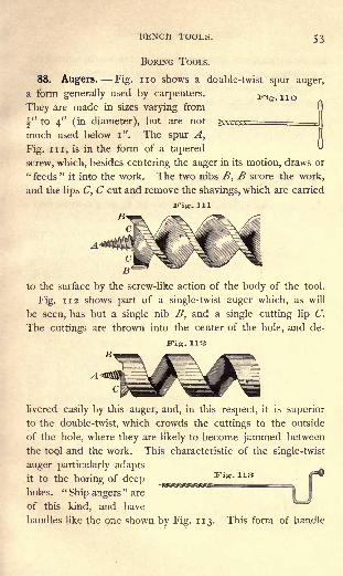
BENCH TOOLS. 53
BORING TOOLS.
88. Augers. Fig. no shows a double-twist spur auger,
a form generally used by carpenters. Fig llo
They are made in sizes varying from
^" to 4" (in diameter), but are not yyv^y- ,
H
much used below i". The spur A,
Fig. in, is in the form of a tapered
screw, which, besides centering the auger in its motion, draws or
"feeds" it into the work. The two nibs B, B score the work,
and the lips C, C cut and remove the shavings, which are carried
Fig. Ill
B*
to the surface by the screw-like action of the body of the tool.
Fig. 112 shows part of a single-twist auger which, as will
be seen, has but a single nib B, and a single cutting lip C.
The cuttings are thrown into the center of the hole, and de-
JFig. 112
livered easily by this auger, and, in this respect, it is superior
to the double-twist, which crowds the cuttings to the outside
of the hole, where they are likely to become jammed between
the tool and the work. This characteristic of the single-twist
auger particularly adapts
it to the boring of deep ^^^.^ Vifs ' 11B
holes."Ship augers
"are
of this kind, and have
handles like the one shown by Fig. 113. This form of handle
if
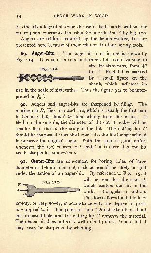
54 BENCH WORK IN WOOD.
has the advantage of allowing the use of both hands, without the
interruption experienced in using the one illustrated by Fig. no.
Augers are seldom required by the bench-worker, but are
presented here because of their relation to other boring tools.
89. Auger-Bits. The auger-bit most in use is shown by
Fig. 114. It is sold in sets of thirteen bits each, varying in
size by sixteenths, from \"to i". Each bit is marked
by a small figure on the
shank, which indicates its
size in the scale of sixteenths. Thus the figure 9 is to be inter-
preted as -fa".
90. Augers and auger-bits are sharpened by filing. The
scoring nib B, Figs, in and 112, which is usually the first part
to become dull, should be filed wholly from the inside. If
filed on the outside, the diameter of the cut it makes will be
smaller than that of the body of the bit. The cutting lip Cshould be sharpened from the lower side, the file being inclined
to preserve the original angle. With the spur in good order,
whenever the tool refuses to "feed," it is clear that the bit
needs sharpening somewhere.
91. Center-Bits are convenient for boring holes of large
diameter in delicate material, such as would be likely to split
under the action of an auger-bit. By reference to Fig. 115, it
will be seen that the spur A,B "_____ _ which centers the bit in the
\vork, is triangular in section.
This form allows the bit to feed
rapidly, or very slowly, in accordance with the degree of pres-
sure applied to it. The point, or "nib," B cuts the fibers about
the proposed hole, and the cutting lip C removes the material.
The center-bit does not work well in end grain. When dull it
may easily be sharpened by whetting.

BENCH TOOLS. 55
92. Expansive Bits are so constructed as to be adjust-
able for holes of any size, within certain limits. There are
several forms in use, one of which is shown by Fig. 116.
This, without the FiSm 11G
movable cutter C,
will bore a hole
f"in diameter, the
screw A centering
and feeding it into the work, B scoring, and a cutting lip in
advance of B (not shown) removing the shavings. When C is
inserted as shown in the figure, in addition to the action just
described, there is a supplementary action on the part of C, its
nib, B', scoring, and its cutting edge removing the chips. The
cutter C is held in place by the screw Z>. By loosening D, C
may be moved from or towards the center of the bit, or taken
out altogether, and replaced by a cutter of different length. By
using a short cutter in the place of C, a hole of any diameter
from f"
to 2" may be bored, and with the cutter shown, any
hole from 2" to 3" may be bored. The range of the bit, there-
fore, is from f"to 3".
93. Small Bits. Bits for boring holes less than \" in diam-
eter are of many forms, but by far the most satisfactory is the
"quill"
bit shown by Fig.Fis - 11T
117. It has no delicate
parts ;if carefully handled
it will not split the mate-
rial; it enters the work rapidly, makes a round, smooth hole,
and when dull can easily be sharpened by whetting or grind-
ing. It will not, however, work with the grain. Quill bits as
small as Ty in diameter are in common use.
Gimlet-bits are illustrated by Fig. 118, which represents one
of the best forms. Most
bits of this class are too
weak to render the ser-
Fig. 118
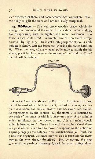
56 BENCH WORK IN WOOD.
vice expected of them, and soon become bent or broken. Theyare likely to split the work and are not easily sharpened.
94. Bit-Braces. The well-made wooden brace, which for
a long time ornamented the walls of the cabinet-maker's shop,
has disappeared, and the lighter and more convenient iron
brace is used in its stead. A simple form of iron brace is rep-
resented by Fig. 119. To insert a bit, grasp the sleeve A and,
holding it firmly, turn the brace out by using the other hand on
B. When the jaws, C, are opened sufficiently to admit the bit
shank, put it in place, reverse the motion of the hand on B, and
the bit will be fastened.
Fig. 118
A ratchet brace is shown by Fig. 120. Its office is to turn
the bit forward while the brace itself, instead of making a com-
plete revolution, has only a forward and backward movement.
As represented by the section AB, the frame c is fastened to
the body of the brace of which it becomes a part, d is a spindle
which terminates in the socket e, and f is a ratchet-wheel,
which is fastened to d. On each side of the ratchet-wheel there
is a pawl which, when free to move in response to the action of
a spring, engages the notches in the ratchet-wheel /. With the
pawls thus engaged, the brace may be used in precisely the same
way as the one already described. But, by turning the ring
^, one of the pawls is disengaged, and the other acting alone

BENCH TOOLS. 57
will move the spindle d only when the brace is moving in one
direction, the pawl simply slipping over the notches of the
ratchet-wheel when the motion is reversed. In this way, a
bit may be driven to any depth although each movement of
the brace may be less than half of a complete turn. By a
proper movement of the ring g, the motion of the bit may be
reversed. ,
Fig. 130
The ratchet-brace is useful in boring holes near walls, or in
corners where it is impossible to turn a common brace.
The size of any brace is indicated by its"swing," that is,
by the diameter of the circle described by , Fig. 119. The
better class are nickel-plated, and are thereby prevented from
rusting.
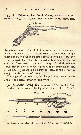
BENCH WORK IN WOOD.
95. A "Universal, Angular, Bit-Stock," such as is repre-
sented by Fig. 121, is, for many purposes, more useful than
Fig. 121
the ratchet-brace. The bit is inserted at A, and a commonbrace is applied at C. The mechanical arrangement of the
parts is such, that, when the brace turns the spindle C, the part
A which holds the bit is also turned, notwithstanding the in-
clination of one part to the other.1
Compared with the ratchet-
brace, this has the advantage of producing a continuous motion
of the bit. By its use a hole may be bored in the corner as
easily as in the middle of a room.
The angle of the joint may be changed from that shown to
one of 1 80 degrees, by an adjustment at D.
96. Automatic Boring Tool. A convenient substitute for
a brad-awl is represented by Fig. 122. The drill, or bit, A is
1 Considered as a mechanical movement, this is known as Hooke's joint.
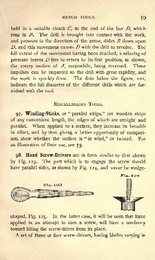
BENCH TOOLS. 59
held in a suitable chuck C, at the end of the bar D, which
runs in B, The drill is brought into contact with the work,
and pressure in the direction of the arrow, slides B down upon
D, and this movement causes D with the drill to revolve. Thefull extent of the movement having been reached, a relaxing of
pressure leaves D free to return to its first position, as shown,
the rotary motion of A, meanwhile, being reversed. These
impulses can be imparted to the drill with great rapidity, and
the work is quickly done. The dots below the figure, 122,
indicate the full diameter of the different drills which are fur-
nished with the tool.
MISCELLANEOUS TOOLS.
97. Winding-Sticks, or "parallel strips," are wooden strips
of any convenient length, the edges of which are straight and
parallel. When applied to a surface, they increase its breadth
in effect, and by thus giving a better opportunity of compari-
son, show whether the surface is"in wind," or twisted. For
an illustration of their use, see 75.
98. Hand Screw-Drivers are in form similar to that shown
by Fig. 123. The part which is to engage the screw should
have parallel sides, as shown by Fig. 1 24, and never be wedge-
K'ig. 1S4I
Fig. 133
shaped, Fig. 125. In the latter case, it will be seen that force
applied in an attempt to turn a screw, will have a tendency
toward lifting the screw-driver from its place.
A set of three or four screw-drivers, having blades varying in

6O BENCH WORK IN WOOD.
size to suit different-sized screws, so that a fairly good fit may
always be made, are indispensable to good work where screws
are much used.Fig. 125
99. Brace Screw-Drivers, instead of having
wooden handles, are provided with shanks for
use in a brace. A good form is shown by
Fig. 126. The brace gives a continuous mo-
tion, andFig. 136
the screw
may be
set much more rapidly byits use than with the hand screw-driver. There are many cases,
however, in which a brace is useless.
100. Hammers. Fig. 127 shows a carpenter's hammer. The
head A is wholly of steel. The face B is hardened so as not
to be injured by repeated blows upon the nail, which is com-
paratively soft, but the idea prevailing among inexperienced
workmen, that the hammer is indestructible, is a false one.
When two bodies are brought together forcibly, as a hammer
Fig. isr
and a nail, the softer body yields, and a change takes place in
its form. If the nail were harder than the hammer, it would not
be injured, but the hammer would show an impression of the
nail head. Careless or ignorant workmen sometimes take an

BENCH TOOLS. 6 1
old file for a punch or a nail-set, and use a hammer upon it.
The file is harder than the hammer, and the result is that the
face of the latter is badly scarred.
The claw C makes the hammer a very effective tool for
withdrawing nails.
Hammers vary in size from seven to twenty ounces ;the
bench-worker usually employs one weighing from fourteen to
sixteen ounces.
101. The Hatchet is a useful tool for bringing large pieces
of material to size roughly, and in skillful hands it may be
used with accuracy as well as effect. When it is comparedwith the hammer, it will be seen that a blade C, Fig. 128, takes
BI
Pig. 128
the place of the claw C, Fig. 127. As an instrument for driv-
ing nails it is clumsy, and the opening d, for withdrawing nails,
amounts to but little. In sharpening, the hatchet is ground on
both sides of the blade, and whetted on an oilstone.
102. Mallets. The difference in effect between a blow
given by a hammer and one given by a mallet is so great that,
although similar in many respects, the two tools are adapted to
widely different uses. A blow from a hard, elastic hammer is
sharp and decisive, and its force is absorbed almost as soon as
it is received. Comparatively speaking, therefore, its effect
must be local. If such a blow is received on a chisel handle,
for example, a large part of its force is wasted in affecting the

62 BENCH WORK IN WOOD.
handle, a part only being transmitted through the handle to
the cutting edge, the only place where it can be of use. Ablow from a soft, less elastic mallet, on the contrary, is more
general in its effect. Much of the force remains for an instant
stored in the mallet, by which it is given out somewhat grad-
ually, allowing time for the impulse to pass beyond the point
where it is received. The effect of two different explosive
agents will serve as an illustration. As compared with nitro-
glycerine, powder burns slowly, and, when put into a rifle barrel,
gradually develops its force upon the bullet until, when the lat-
ter reaches the end of the barrel, it has gained velocity enoughto carry it a mile or more. But if a charge of nitro-glycerine,
Fig. 130
having a total explosive force no greater than that of the pow-
der, be substituted, the result will be very different. The rapid-
ity with which nitro-glycerine burns the suddenness of the
impulse is such that, before the bullet can respond to its influ-
ence, the breach of the barrel is destroyed.
The blow of a mallet on a chisel resembles the action of
powder on a bullet. It is a pushing action, and, in this respect,
is unlike that of the hammer. A chisel, therefore, will be
driven deeper into the work by a blow from a mallet than byone of the same force from a hammer, while a chisel handle
which has withstood blows from a mallet for years, may be
shattered in a single hour by use under a hammer.
An excellent form of mallet is shown by Fig. 129.

BENCH TOOLS. 63
103. Sand-Paper is neither a tool nor an appliance, strictly
speaking, but, on account of its tool-like action, it should be
mentioned with them. The "sand" used in making sand-paper
is crushed quartz, and is very hard, angular, and sharp. It is
graded as to degree of coarseness, by precipitation, and then
glued to paper. The finest sand-paper is marked oo, from which
the gradations run o, , i, i, 2, 2^, and 3, which is the coarsest.
104. Miter-Boxes are useful in cutting the ends of light
strips of wood at an angle of 45 degrees ; they are frequently
adapted to cutting at other angles. When of wood, like the
one represented by Fig. 219, they are usually made by the
workman himself.
A wooden miter-box is composed of three pieces a bot-
tom and two sides. It is necessary that the bottom piece
be uniform in width and thickness, and have jointed edges, and
it is well to prepare the other pieces in the same way. After
the box is nailed, the sides should be square with the outside
face of the bottom piece ; this surface may now be used as
a working-face. Lay off across the working-face two lines at a
distance apart equal to the width of the face, thus forming with
the outside edges of the box, a square. The diagonals of this
square will represent the two oblique cuts, one marked c, and
the one taken by the saw, Fig. 219. Project up the sides such
lines from the points thus fixed, as will be useful in making the
cuts;the sawing is then done with the back-saw. No special
directions are required for laying off the cut d.
105. Iron Miter-Boxes are ,^_ B Fig. iso
now in general use. The ac-
curacy with which work maybe done by the use of one
will more than compensate anybench-worker for the moneyinvested in it. Fig. 130 may be taken as a type ;
the work A

64 BENCH WORK IN WOOD.
is supported by the frame as shown, while the proper position of
the saw is maintained by the uprights B, which, in the sawing
process, slide down into the standards C. The saw may be set
at any angle with the back of the box D, by swinging the frame
E, which supports the standards C ;E is held in position by a
suitable fastening operated by F.
1 06. Bench Clamps are useful in holding two or more pieces
of material together temporarily. They are particularly valu-
able for keeping pieces that have been glued, in place until they
are dry.
Wooden clamps, or hand-screws, are of the form shown by
Fig. 131. The whole length of the jaws, AB and A'B', maybe made to bear evenly upon the work, or to bear harder at
certain points, as AA' or BB'.
Iron clamps are illustrated by Fig. 132, but the mechanical
arrangement differs in different makes. Such clamps are very
Fig. 13S
useful in many kinds of work, but, all things considered, it is
doubtful whether they are as serviceable to the bench-worker
as the wooden ones just described.
107. Grindstones are selected with reference to their"grit."
A coarse, soft-grit stone will remove material much more rap-
idly than one of finer grit, but the surface produced will be
very rough compared with that produced by the other. Thus,
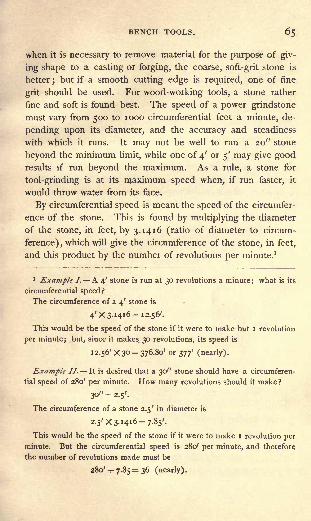
BENCH TOOLS. 65
when it is necessary to remove material for the purpose of giv-
ing shape to a casting or forging, the coarse, soft-grit stone is
better ; but if a smooth cutting edge is required, one of fine
grit should be used. For wood-working tools, a stone rather
fine and soft is found best. The speed of a power grindstone
must vary from 500 to 1000 circumferential feet a minute, de-
pending upon its diameter, and the accuracy and steadiness
with which it runs. It may not be well to run a 20" stone
beyond the minimum limit, while one of 4' or 5' may give goodresults if run beyond the maximum. As a rule, a stone for
tool-grinding is at its maximum speed when, if run faster, it
would throw water from its face.
By circumferential speed is meant the speed of the circumfer-
ence of the stone. This is found by multiplying the diameter
of the stone, in feet, by 3.1416 (ratio of diameter to circum-
ference) ,which will give the circumference of the stone, in feet,
and this product by the number of revolutions per minute. 1
1 Example /. A 4' stone is run at 30 revolutions a minute; what is its
circumferential speed?
The circumference of a 4' stone is
4' X 3-1416= 12.56'.
This would be the speed of the stone if it were to make but I revolution
per minute; but, since it makes 30 revolutions, its speed is
12.56' X 30= 376.80' or 377' (nearly).
Example II. It is desired that a 30" stone should have a circumferen-
tial speed of 280' per minute. How many revolutions should it make?
30" = 2.5'.
The circumference of a stone 2.5' in diameter is
2.5' x 3-1416 =7.85'.
This would be the speed of the stone if it were to make I revolution per
minute. But the circumferential speed is 280' per minute, and therefore
the number of revolutions made must be
280' -T- 7.85= 36 (nearly).

66 BENCH WORK IN WOOD.
1 08. Water is used on a stone as a means of carrying off
the heat resulting from friction between stone and tool;
it also
washes away the particles of stone and steel that come from
the grinding, and which, without the water, would fill the inter-
stices between the cutting points of the stone, and make the
surface so smooth as to be useless.
A grindstone, when not in use, should not stand in or over
water. Water softens a stone, and one unequally exposed to
moisture will be found softest in such places as are most
exposed. When brought into use, the softer parts wear awaymore rapidly than the others, causing the stone to become " out
of round." Water is best supplied from a tank, or from service
pipes, so arranged that it may be shut off when the stone is not
running, the drip-pan under the stone being at all times per-
fectly drained. After every precaution has been taken, the
stone will in time become untrue and need attention.
109. To True a Grindstone. When a stone becomes
untrue, or the outline of the face, which should be slightly con-
vex, becomes concave, it may be corrected by using a piece of
soft iron as a turning tool, the stone being run dry. The action
of the tool may be explained as follows : the soft iron allows
small particles of the stone to imbed themselves in its surface,
from which position they act against the revolving stone, and
the cutting is done by these imbedded particles and not by the
iron. The latter is worn in the process, however, and, as its
cutting surface becomes enlarged, it should be turned to bring
a new angle or face into action. This operation is easily per-
formed by using a piece of gas pipe (about i") for a turning tool.
no. Truing Devices are now generally attached to power
grindstones. They are of several forms, of which that shown
by Fig. 133 may be taken as an example. The base of this at-
tachment is secured to the grindstone frame as near the stone as
may be convenient. A is a hardened steel screw which revolves
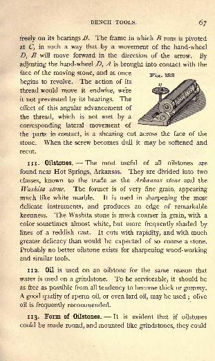
BENCH TOOLS. 6/
freely on its bearings B. The frame in which B runs is pivoted
at C, in such a way that by a movement of the hand-wheel
D, B will move forward in the direction of the arrow. Byadjusting the hand-wheel D, A is brought into contact with the
face of the moving stone, and at once Fio. 133
begins to revolve. The action of its
thread would move it endwise, were
it not prevented by its bearings. The
effect of this angular advancement of
the thread, which is not met by a
corresponding lateral movement of
the parts in contact, is a shearing cut across the face of the
stone. When the screw becomes dull it may be softened and
recut.
in. Oilstones. The most useful of all oilstones are
found near Hot Springs, Arkansas. They are divided into two
classes, known to the trade as the Arkansas stone and the
Washita stone. The former is of very fine grain, appearing
much like white marble. It is used in sharpening the most
delicate instruments, and produces an edge of remarkable
keenness. The Washita stone is much coarser in grain, with a
color sometimes almost white, but more frequently shaded bylines of a reddish cast. It cuts with rapidity, and with much
greater delicacy than would be expected of so coarse a stone.
Probably no better oilstone exists for sharpening wood-workingand similar tools.
112. Oil is used on an oilstone for the same reason that
water is used on a grindstone. To be serviceable, it should be
as free as possible from all tendency to become thick or gummy.A good quality of sperin oil, or even lard oil, may be used
;olive
oil is frequently recommended.
113. Form of Oilstones. It is evident that if oilstones
could be made round, and mounted like grindstones, they could

68 BENCH WORK IN WOOD.
be used more effectively than when only a small block is avail-
able. The reason they are not so mounted is that, in their
native bed, the whetstone layers are traversed in every direction
by veins of hard quartz, which, if allowed to enter into a finished
stone, would destroy the- cutting edge of any tool that might
be applied to it. It is so uncommon to find large pieces of
whetstone free from the quartz, that disks above 4" or 5" in
diameter can be afforded only by those to whose work they are
indispensable.
For bench purposes, Washita stones are about i" x 2" x 7" ;
but no attempt is made to have them
of any uniform size. Such a stone, when
set into a block and provided with a
cover to keep out the dust, is ready
for use. See Fig. 134. Its surface
should be kept as nearly as possible straight, in the direction of
its length, and should never be hollowed across its breadth.
When out of shape it must be trued.
114. Slips of Washita stone whose cross-sections are round,
square, triangular, etc., are suppliedFig. 135 by the trade. A wedge-shaped slip
is represented by Fig. 135 ;it is a
form extremely useful to the bench-
worker.
115. To True an Oilstone, mix water with sharp sand until
the mixture is thin enough to run. Apply a quantity of this
to the surface of a flat board or plank, and, with the face that
is to be trued in contact with the sand-covered board, move
the stone about, frequently changing the direction of its motion.
Under this treatment, the surface of the stone will be evened
up rapidly. If the sand that is first applied becomes dull, it
may be replaced by new.
BENCH TOOLS. 69
Another, and usually a more convenient way, consists in sub-
stituting for the sand a sheet of sand-paper tacked over the
edge of the board. Coarse paper may be used at first, and
afterwards a finer grade selected for finishing the work.


PART II.
BENCH WORK.1
116. No work at the bench (9-13) is more important than
that relating to the location and production of lines. Careless-
ness or want of skill in this will always be manifest in the fin-
ished work. To the beginner it may seem monotonous, and
even hard, to stand at the bench several hours before turning
a shaving ;but he must understand that a scratch cannot be
called a line, and that patience and accuracy are the chief
requisites in skillful manipulation.
117. Location of Points (14-17). All measurements must
begin somewhere. The greater the number of points from which
to begin, the more chances there are for mistakes. Thus in
1 NOTE. The material, or "stock," needed for the exercises of the
course should be straight-grained, free from knots, well-seasoned, and
machine-dressed. A good quality of either white pine or yellow poplar is
to be preferred. Good work cannot be done in poor material.
By easy steps the operations to be performed become more and more
difficult. The student should not advance to a new exercise until the pre-
ceding one has been completed in a good, workman-like manner. A fail-
ure, unless the result of accident, should invariably be followed by another
trial of the exercise. Otherwise, a careless habit is encouraged.
The course may appear brief, but experience has demonstrated its com-
pleteness as a preparation for constructive work in any of the lines to
which it leads. After the fifteen exercises have been finished, if time
remains, any ordinary piece of bench work may be undertaken.
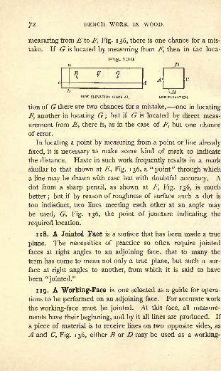
BENCH WORK IN WOOD.
measuring from E to F, Fig. 136, there is one chance for a mis-
take. If G is located by measuring from F, then in the loca-
tion of G there are two chances for a mistake, one in locating
F, another in locating G ;but if G is located by direct meas-
urement from E, there is, as in the case of F, but one chance
of error.
In locating a point by measuring from a point or line already
fixed, it is necessary to make some kind of mark to indicate
the distance. Haste in such work frequently results in a mark
similar to that shown at E, Fig. 136, a "point" through which
a line may be drawn with ease but with doubtful accuracy. Adot from a sharp pencil, as shown at F, Fig. 136, is much
better;but if by reason of roughness of surface such a dot is
too indistinct, two lines meeting each other at an angle maybe used, G, Fig. 136, the point of juncture indicating the
required location.
118. A Jointed Face is a surface that has been made a true
plane. The necessities of practice so often require jointed
faces at right angles to an adjoining face, that to many the
term has come to mean not only a true plane, but such a sur-
face at right angles to another, from which it is said to have
been "jointed."
119. A Working-Face is one selected as a guide for opera-
tions to be performed on an adjoining face. For accurate work
the working-face must be jointed. At this face, all measure-
ments have their beginning, and by it all lines are produced. If
a piece of material is to receive lines on two opposite sides, as
A and C, Fig. 136, either B or D may be used as a working-
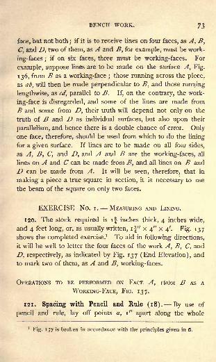
BENCH WORK. 73
face, but not both;
if it is to receive lines on four faces, as A, B,
C, and D, two of them, as A and B, for example, must be work
ing-faces ;if on six faces, three must be working- faces. For
example, suppose lines are to be made on the surface A, Fig.
136, from B as a working-face ;those running across the piece,
as ab, will then be made perpendicular to B, and those running
lengthwise, as cd, parallel to B. If, on the contrary, the work-
ing-face is disregarded, and some of the lines are made from
B and some from D, their truth will depend not only on the
truth of B and D as individual surfaces, but also upon their
parallelism, and hence there is a double chance of error. Onlyone face, therefore, should be used from which to do the lining
for a given surface. If lines are to be made on all four sides,
as A, B, C, and D, and A and B are the working-faces, all
lines on A and C can be made from B, and all lines on B and
D can be made from A. It will be seen, therefore, that in
making a piece a true square in section, it is necessary to use
the beam of the square on only two faces.
EXERCISE No. i. MEASURING AND LINING.
1 20. The stock required is if inches thick, 4 inches wide,
and 4 feet long, or, as usually written, if" x 4" X 4'. Fig. 137
shows the completed exercise.1 To aid in following directions,
it will be well to letter the four faces of the work A, B, C, and
D, respectively, as indicated by Fig. 137 (End Elevation), and
to mark two of them, as A and B, working-faces.
OPERATIONS TO BE PERFORMED ON FACE A, FROM B AS A
WORKING-FACE, FIG. 137.
121. Spacing with Pencil and Rule (18). By use of
pencil and rule, lay off points a, i" apart along the whole
1Fig. 137 is broken in accordance with the principles given in 6.

74 BENCH WORK IN WOOD.
length of the piece, the line of points being kept straight by
preserving a uniform distance between them and the working-
face B. This distance may be anything that is convenient,
and will be sufficiently accurate if determined by the eye.
Fig. 13^Scale, 2l'
aaaaaaaaa \a a a a a
gd
Face A.Working Face B.
rking Face A.
Face B.
END ELEVATIC
Face D.\ Working Face A.
Working Face B. .
EFace C.
122. Cross-lining with Pencil and Framing-Square (19-
21 ). The points having been located, draw through each a
line, as ab (Face A), using the framing-square and pencil.
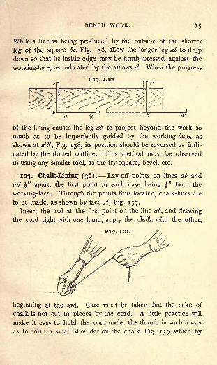
BENCH WORK. 75
While a line is being produced by the outside of the shorter
leg of the square be, Fig. 138, allow the longer leg ab to drop
down so that its inside edge may be firmly pressed against the
working-face, as indicated by the arrows d. When the progress
Fig. 138
of the lining causes the leg ab to project beyond the work so
much as to be imperfectly guided by the working- face, as
shown at a'b 1
, Fig. 138, its position should be reversed as indi-
cated by the dotted outline. This method must be observed
in using any similar tool, as the try-square, bevel, etc.
123. Chalk-Lining (36). Lay off points on lines ab and
ad "apart, the first point in each case being ^" from the
working-face. Through the points thus located, chalk-lines are
to be made, as shown by face A, Fig. 137.
Insert the awl at the first point on the line ab, and drawingthe cord tight with one hand, apply the chalk with the other,
K"ig. 130
beginning at the awl. Care must be taken that the cake of
chalk is not cut to pieces by the cord. A little practice will
make it easy to hold the cord under the thumb in such a wayas to form a small shoulder on the chalk, Fig. 139, which by
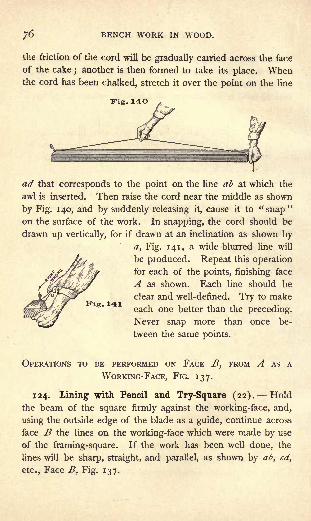
;6 BENCH WORK IN WOOD.
the friction of the cord will be gradually carried across the face
of the cake; another is then formed to take its place. When
the cord has been chalked, stretch it over the point on the line
!Fig. 140
ad that corresponds to the point on the line ab at which the
awl is inserted. Then raise the cord near the middle as shown
by Fig. 140, and by suddenly releasing it, cause it to "snap
"
on the surface of the work. In snapping, the cord should be
drawn up vertically, for if drawn at an inclination as shown by
a, Fig. 141, a wide blurred line will
be produced. Repeat this operation
for each of the points, finishing face
A as shown. Each line should be
clear and well-defined. Try to make
each one better than the preceding.
Never snap more than once be-
tween the same points.
Fig. 141
OPERATIONS TO BE PERFORMED ON FACE B, FROM A AS A
WORKING-FACE, FIG. 137.
124. Lining with Pencil and Try-Square (22). Hold
the beam of the square firmly against the working-face, and,
using the outside edge of the blade as a guide, continue across
face B the lines on the working-face which were made by use
of the framing-square. If the work has been well done, the
lines will be sharp, straight, and parallel, as shown by ab, cd,
etc., Face B, Fig. 137.
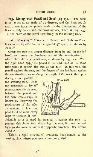
BENCH WORK. 77
125. Lining with Pencil and Bevel (23-25). The bevel
is to be set at an angle of 45 degrees, and the lines ag, fg,
etc., drawn from the points made by the intersection of the
lines already drawn and the working-face, Face B, Fig. 137.
Let the beam of the bevel bear firmly on the working-face.
126. "Gauging" Lines with Pencil and Rule. These
lines, as ik, hi, etc., are to be spaced \" apart, as shown byFace B.
Grasp the rule at a proper distance from its end, in the left
hand, and press the forefinger against the working-face, to
which the rule is perpendicular, as shown by Fig. 142. With
the right hand apply the pencil to the work, and at the same
time press it against the end of the rule. In this way, the
pencil against the rule, and the fingers of the left hand against
the working-face, move along the length of the work, thus pro-
ducing a line parallel to
the working-face. It is
not necessary to lay off
points, since the distance
between the pencil and
the edge can always be
known by observing the
graduations of the rule.
In making a line, the
pencil will be more easily
kept in position if con-
siderable force is used in pressing it against the rule;
to
prevent this force from displacing the rule, it must be met
by a greater force acting in the opposite direction. See arrows
c and d.
This is a rapid method of producing lines parallel to the
working-face, where exactness is not demanded.
Fig. 143
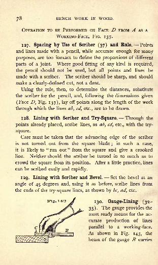
/8 BENCH WORK IN WOOD.
OPERATION TO BE PERFORMED ON FACE D FROM A AS A
WORKING-FACE, FIG. 137.
127. Spacing by Use of Scriber (37) and Rule. Points
and lines made with a pencil, while accurate enough for manypurposes, are too inexact to define the proportions of different
parts of a joint. Where good fitting of any kind is required,
the pencil should not be used, but all points and lines be
made with a scriber. The scriber should be sharp, and should
make a clearly-defined cut, not a dent.
Using the rule, then, to determine the distances, substitute
the scriber for the pencil, and, following the dimensions given
(Face D, Fig. 137), lay off points along the length of the work
through which the lines ab, cd, etc., are to be drawn.
128. Lining with Scriber and Try-Square. Through the
points already placed, scribe lines, as ab, cd, etc., with the try-
square.
Care must be taken that the advancing edge of the scriber
is not turned out from the square blade;
in such a case,
it is likely to " run out" from the square and give a crooked
line. Neither should the scriber be turned in so much as to
crowd the square from its position. After a little practice, lines
can be scribed easily and rapidly.
129. Lining with Scriber and Bevel. Set the bevel at an
angle of 45 degrees and, using it as before, scribe lines from
the ends of the try-square lines, as shown by be, ad, etc.
Fig. 143 jj 130. Gauge-Lining (32-
35). The gauge provides the
most ready means for the ac-
curate production of lines
parallel to a working-face.
As shown in Fig. 143, the
beam of the gauge B carries
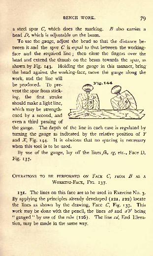
BENCH WORK. 79
a steel spur C, which does the marking. B also carries a
head D, which is adjustable on the beam.
To use the gauge, adjust the head so that the distance be-
tween it and the spur C is equal to that between the working-
face and the required line;
then close the fingers over the
head and extend the thumb on the beam towards the spur, as
shown by Fig. 143. Holding the gauge in this manner, bring
the head against the working- face, move the gauge along the
work, and the line will
be produced. To pre-
vent the spur from stick-
ing, the first stroke
should make a light line,
which may be strength-
ened by a second, and
even a third passing of
the gauge. The depth of the line in each case is regulated by
turning the gauge as indicated by the relative position of Yand X, Fig. 144. It is obvious that no spacing is necessary
when this tool is to be used.
By use of the gauge, lay off the lines fh, eg, etc., Face D,
Fig. 137-
OPERATIONS TO BE PERFORMED ON FACE C, FROM B AS A
WORKING-FACE, FIG. 137.
131. The lines on this face are to be used in Exercise No. 3.
By applying the principles already developed (121, 122) locate
the lines as shown by the drawing, Face C, Fig. 137. This
work may be done with the pencil, the lines ab and a't>' being"gauged
"by use of the rule (126). The line cd, End Eleva-
tion, may be made in the same way.
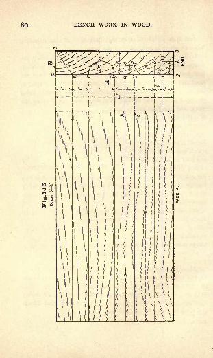
So BENCH WORK IN WOOD.

BENCH WORK. 8l
EXERCISE No. 2.
PRACTICE WITH CHISEL AND GOUGE (39, 40, and 42).
The stock required is |" X 4?" X 8 "-
Fig. 145 shows the lines that are needed, all of which are
produced as explained in the foregoing exercise, except the
arcs of circles, which must be put in with the dividers (26) ;
A and B are working-faces. An end elevation of the finished
piece is represented by Fig. 146.
Fig. 14:7
132. To remove the Portion abc, Fig. 145. It is always
best, in removing surplus wood with the chisel, to cut across
the grain, as any attempt to carry the cutting edge along
the grain is quite sure to result in a splitting action, the
chisel following the grain of the wood,
which splits ahead of it, and pre-
vents the operator from controlling its
course. In removing the portion abc,
the work should be held in the vise with
the working-face A toward the operator.
A i" chisel will be found of convenient
size. Beginning at one end, make suc-
cessive cuts with the chisel, as shown
by Fig. 147. Each stroke of the chisel
should cut almost to the full depth re-
quired (i.e. remove a shaving from the
face of nearly the whole triangle abc},
the thickness of the cutting varying with
the character of the material and the
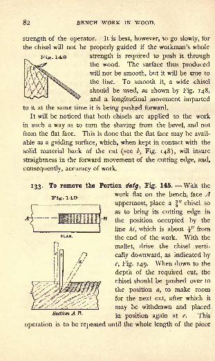
82 BENCH WORK IN WOOD.
strength of the operator. It is best, however, to go slowly, for
the chisel will not be properly guided if the workman's whole
148 strength is required to push it through
the wood. The surface thus producedwill not be smooth, but it will be true to
the line. To smooth it, a wide chisel
should be used, as shown by Fig. 148,
and a longitudinal movement imparted
to it at the same time it is being pushed forward.
It will be noticed that both chisels are applied to the work
in such a way as to turn the shaving from the bevel, and not
from the flat face. This is done that the flat face may be avail-
able as a guiding surface, which, when kept in contact with the
solid material back of the cut (see b, Fig. 148), will insure
straightness in the forward movement of the cutting edge, and,
consequently, accuracy of work.
133. To remove the Portion defg, Fig. 145. With the
Fig. 140
-n
work flat on the bench, face Auppermost, place a f
"chisel so
as to bring its cutting edge in
the position occupied by the
line hi, which is about " from
the end of the work. With the
mallet, drive the chisel verti-
cally downward, as indicated by
c, Fig. 149. When down to the
depth of the required cut, the
chisel should be pushed over to
the position a, to make room
for the next cut, after which it
may be withdrawn and placedSection A B.
jn pOS{tjon agam at gt This
operation is to be repeated until the whole length of the piece
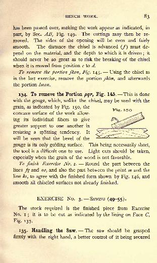
BENCH WORK. 83
has been passed over, making the work appear as indicated, in
part, by Sec. AB, Fig. 149. The cuttings may then be re-
moved. The sides of the opening will be even and fairly
smooth. The distance the chisel is advanced (/) must de-
pend on the material, and the depth to which it is driven;
it
should never be so great as to risk the breaking of the chisel
when it is moved from position c to d.
To remove the portion jkon, Fig. 145. Using the chisel as
in the last exercise, remove the portion jklm, and afterwards
the portion Imon.
134. To remove the Portion pqr, Fig. 145. This is done
with the gouge, which, unlike the chisel, may be used with the
grain, as indicated by Fig. 1150, thec , , ,, Fig. 150
concave surface of the work allow-
ing its individual fibers to give
greater support to one another in
resisting a splitting tendency. It
will be seen that the bevel of the
gouge is its only guiding surface. This being necessarily short,
the tool is a difficult one to use. Light cuts should be taken,
especially when the grain of the wood is not favorable.
To finish Exercise No. 2. Round the part between the
lines fg and no, and also the part between the point m and the
line ks, to agree with the finished form shown by Fig. 146, and
smooth all chiseled surfaces not already finished.
EXERCISE No. 3. SAWING (49-55).
The stock required is the finished piece from Exercise
No. i; it is to be cut as indicated by the lining on Face C,
Fig- 137-
135. Handling the Saw. The saw should be grasped
firmly with the right hand, a better control of it being secured
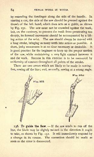
84 BENCH WORK IN WOOD.
by extending the forefinger along the side of the handle. In
starting a cut, the side of the saw should be pressed against the
thumb of the left hand, which then acts as a guide, as shown
by Fig. 151. The saw must not be crowded against the work,
but, on the contrary, to prevent the teeth from penetrating too
deeply, its forward movement should be accompanied by a lift-
ing action of the wrist. The saw should always be moved with
a long stroke, bringing as many teeth into action as possible. A
short, jerky movement is at no time necessary or desirable. It
is good practice for the beginner to keep up the proper motion
of the saw, while maintaining a very light contact between it
and the work. Success in this exercise is to be measured by
uniformity of contact throughout all points of the stroke.
There are two errors which are likely to be made in sawing :
first, sawing off the line; and, secondly, sawing at a wrong angle.
Kig. 151
136. To guide the Saw. If the saw tends to run off the
line, the blade may be slightly twisted in the direction it ought
to take, as shown by Fig. 152. It will immediately respond bya change in its course. The correction should be made as
soon as the error is discovered.
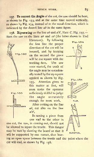
BENCH WORK.
Kig. 153
Fig.
137. To correct the Angle of the cut, the saw should be bent,
as shown by Fig. 153, and at the same time moved vertically,
as shown by Fig. 154, instead of in the usual direction, which is
indicated by the dotted line ab in the same figure.
138. Rip-sawing on the line ab and a'P, Face C, Fig. 137.
Start the saw on the lines ab and cd (the latter shown in End
Elevation). By following
the first line the proper
direction of the cut will be
insured, and by keeping
on the second the piece
will be cut square with the
working -face. The saw
once started, the truth of
the angle may be occasion-
ally tested by the try-square
applied as shown by Fig.
155. Attention given to
this matter at first, will
soon make the operator
sufficiently skillful to judgethe angle accurately
enough for most work.
After cutting on the line
ab, cut also on the line
of**.
In sawing a piece from
one end to the other in
one cut, the saw, in coming out, should not
be allowed to injure the trestle. This danger
may be met by slanting the board so that itC.I.C.VM i tun.
will be supported by one corner, thus leav-
ing an open space between the trestle and the point where the
cut will end, as shown by Fig. 156.
Fig. 15o

86 BENCH WORK IN WOOD.
139- Cross-cutting on the lines ef and^, Face C, Fig. 137.
Observe the general directions that have already been given.
When the piece that is being cut is almost divided, there
is danger that the uncut portion may break and splinter. This
tendency must be guarded against by properly supporting the
work, either by the hand or by a suitable arrangement of the
trestles.
EXERCISE No. 4. PLANING (66-74).
The stock required is the pieces resulting from Exercise
No. 3.
140. In grasping a plane, there is always shown a disposition
to place the thumb of the left hand on the right side of the
plane. This should not be done; for, as will be seen by Fig. 157,
when the plane is drawn back, the arm, by contact with the
body, becomes stiffened, and the motion of the plane restricted.
The hand, therefore, should be so turned as to bring the thumb
on the left side, as shown by Fig. 158. Held in this manner,
the plane may be easily carried well forward and well back.
Fig. 157 TFig.lOS
When the surface of the work is large, begin to plane at its
right-hand end. With a series of easy strokes pass across the
face of the work, then step forward and take a second series of

BENCH WORK. 8/
strokes, and so on until the whole surface has been passed over.
In the first series of strokes it is necessary to draw the plane off
the work, as shown by Fig. 159. In doing this, sufficient
pressure must be exerted in the direc-ITig.150
tion of the arrow to overcome any
tendency to tip, as indicated by the J
dotted outline ;in the last series of jS^^r^^
strokes the wrist may, for the same
reason, be rested easily on the back of the plane. To make
the strokes between the ends properly, the plane should be
lifted so that the shaving may be finished before the forward
movement of the plane ceases. The plane need not be lifted
bodily from the work. The natural, slightly-upward move-
ment of the arm when stretched out, as shown by Fig. 160,
will accomplish all that is necessary.
Fig. 160
If the plane is allowed full contact with the work on the
backward stroke, a dulling effect on the cutting edge is pro-
duced, especially if the work is rough and gritty. Under
such circumstances, it is better to raise the plane from the
work entirely, or turn it on its edge, or draw it back in the
position shown by Fig. 160. On small, clean surfaces, how-
ever, it is best to disregard this caution, since sharpening
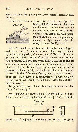
88 BENCH WORK IN WOOD.
takes less time than placing the plane before beginning each
stroke.
In planing a narrow surface, for example, the edge of a
ITig. 161 board, difficulty in keeping the planeon the work may be overcome by
grasping it in such a way that the
fingers of the left hand, while press-
ing against the face of the plane, maymaintain a light contact with the
work, as shown by Fig. 161.
141. The mouth of a plane sometimes becomes clogged,
and, as a result, the cutting ceases. This may be caused
by a dull cutting edge, which scrapes off fibers which it can-
not cut;
or by the low set of the cap on the iron;or by a
bad fit between cap and iron, which allows a shaving to find its
way between them, thus forming an obstruction to the passage
of other cuttings. In new planes, the stoppage may be due to
narrowness of the mouth, which will not allow a thick shaving
to pass. It should be remembered, however, that narrowness
of mouth is an element in the production of smooth work, and
for this reason the opening should be no wider than is abso-
lutely necessary.
To preserve the face of the plane, apply occasionally a few
drops of lubricating oil.
142. Jointing the sawed edge of the if" X3" X 16" piece
from Exercise No. 3, to finish at if" X 2f" X 16". Set the
Fig. 163
gauge at 2|" and from the working-face B, Fig. 162, gauge
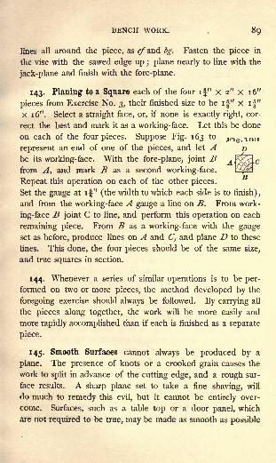
BENCH WORK. 89
lines all around the piece, as e/a.nd bg. Fasten the piece in
the vise with the sawed edge up ; plane nearly to line with the
jack-plane and finish with the fore-plane.
143. Planing to a Square each of the four if" x 2" x 16"
pieces from Exercise No. 3, their finished size to be if" x if"
X 1 6". Select a straight face, or, if none is exactly right, cor-
rect the best and mark it as a working-face. Let this be done
on each of the four pieces. Suppose Fig. 163 to jrig.iea
represent an end of one of the pieces, and let Abe its working-face. With the fore-plane, joint Bfrom A, and mark B as a second working-face.
Repeat this operation on each of the other pieces.
Set the gauge at if" (the width to which each side is to finish),
and from the working-face A gauge a line on B. From work-
ing-face B joint C to line, and perform this operation on each
remaining piece. From B as a working-face with the gaugeset as before, produce lines on A and C, and plane D to these
lines. This done, the four pieces should be of the same size,
and true squares in section.
144. Whenever a series of similar operations is to be per-
formed on two or more pieces, the method developed by the
foregoing exercise should always be followed. By carrying all
the pieces along together, the work will be more easily and
more rapidly accomplished than if each is finished as a separate
piece.
145. Smooth Surfaces cannot always be produced by a
plane. The presence of knots or a crooked grain causes the
work to split in advance of the cutting edge, and a rough sur-
face results. A sharp plane set to take a fine shaving, will
do much to remedy this evil, but it cannot be entirely over-
come. Surfaces, such as a table top or a door panel, which
are not required to be true, may be made as smooth as possible
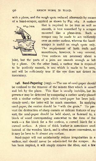
9O .BENCH WORK IN WOOD.
with a plane, and the rough spots reduced afterwards by means
of a hand-scraper, applied as shown by Fig. 164. A surface
tnat *s re(luired to be true as well as
smooth, is best smoothed by a scraper
mounted like a plane-iron. Such a
scraper may be made to act uniformlyover an entire surface, whereas the hand-
scraper is useful on rough spots only.
The requirement of both truth and
smoothness, however, is very unusual.
True surfaces are necessary about a
joint, but the parts of a joint are smooth enough as left
by a plane. On the other hand, a surface that is required
to be perfectly smooth, is one which is made to be seen,
and will be sufficiently true if the eye does not detect its
inaccuracy.
146. Sand-Papering (103). The use of sand-paper should
be confined to the removal of the minute fiber which is raised
and left by the plane. This fiber is usually invisible, but its
presence may be detected by comparing a surface newly-planedwith a similar surface upon which sand-paper has been judi-
ciously used ; the latter will be much smoother. In applying
sand-paper, the motion should be " with the grain." To pre-
vent the destruction of sharp corners or delicate features of any
sort, the sand-paper should be held about, or fastened to, a
block of wood corresponding somewhat to the form of the
work a flat block for a flat surface, a curved block for a
curved surface. A piece of thick leather is sometimes used
instead of the wooden block, and is often more convenient, as
it may be bent to fit almost any surface.
Sand-paper will not satisfactorily reduce irregularities in a
surface, and should never be substituted for the scraper. As
has been implied, it will simply remove the fiber, and a few

BENCH WORK.
strokes arc generally found to be sufficient;more are likely to
result in injury.
EXERCISE No. 5. Box.
The stock required is f" X 6" x 24^" ;
it must be lined as
shown by Fig. 165, and cut into five pieces. The finished box
is shown by Fig. 166.
Fig. 165
Scale. i!*l'
147. If on each of the five pieces there is a surface suffi-
ciently true for a working-face, it should be marked as such ;
otherwise, a working-face should
be made. From the working-
face joint one edge on each
piece and mark it as the work-
ing-edge. Set the gauge at 2|"
(the inside depth of the box)and gauge the side and end
pieces to this depth, after which
joint them to line. From the
working edge, with the try-
square, scribe on the working-
face of all the pieces, including
the bottom, a line about " from
one end. With the back-saw
(56) cut these ends, being care-ELEVATION
ful to keep on the outside of the line (148). The work
may be held on the bench-hook, as shown by Fig. 167.

92 BENCH WORK IN WOOD.
In starting the cut, the saw may be made to act across the
angle of the work in the direction of the line ab, but should
gradually be brought to the position shown, its motion being
parallel to the face of the work, and its stroke long enough to
bring every tooth into action. The position of the saw in Fig.
167, together with the dotted outline, shows a proper range of
movement.
The ends, when sawed, should be square with the work-
ing-face and working-edge. If the cut is a poor one, a
second may be taken by removing just enough material to
hold the saw;
if it is only a little"out," it will be best, in
this case, to pass the error for a time. One end of each hav-
ing been squared, the pieces may now be brought to length.
On one of the two pieces which are to form the ends of the
box, lay off and scribe a line 4" from the squared end. Meas-
ure the second end piece by the first to insure the same length
for both, whether the measurement is just 4" or not. Next, on
one of the two side pieces, 9^" from the squared end, scribe a
line for sawing and, using the first piece as a measure, lay off a
similar line on the second side piece and also on the bottom
piece. All the pieces having been thus lined, they may be cut
with the back-saw, after which all but the bottom piece will be
of the dimensions required.
148. Sawing "outside of the line" may be illustrated as fol-
lows : if two lines are made on a piece of work just 12" apart,
and the portion between cut out by sawing exactly on the lines,

BENCH WORK. 93
it is obvious that the piece will be less than 12" long by half
the width of the saw kerf at each end, or, adding the two de-
ficiencies, by the width of one kerf, Ty or more.
The appearance of an end when cut outside of a
line will be that shown by Fig. 168. The smooth
line along the upper surface, represents the cut
made by the scriber in lining the material;the rest shows the
work of the saw.
149. Nailing (254-256). The side and end pieces are to
be nailed, as shown by Fig. 169, three 6-penny casing nails
being used at each angle. When brought together, the pieces
must be flush pretty nearly right will not do.
Nails, when seen in a certain position, appear equal in width
throughout their length, A, Fig. 1 70 ;while a view at right
angles to the first, shows them wedge-shaped, B, Fig. 1 70. In
. 1GO
Fig. 170A B
starting a nail, the line represented by a must be placed across
the grain of the wood, so that the point will cut the fibers
which are displaced. If the line b is placed across the grain,
a few only of the fibers will be severed, and the others will be
simply pressed apart by the inclined sides of the nail, an action
which is quite likely to split the work.
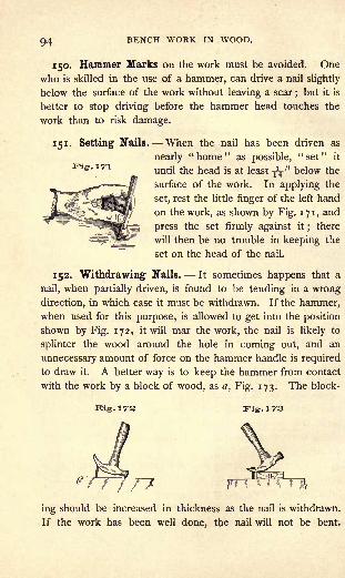
94 BENCH WORK IN WOOD.
150. Hammer Marks on the work must be avoided. One
who is skilled in the use of a hammer, can drive a nail slightly
below the surface of the work without leaving a scar ; but it is
better to stop driving before the hammer head touches the
work than to risk damage.
151. Setting Nails. When the nail has been driven as
nearly "home" as possible, "set" it
until the head is at least ^" below the
surface of the work. In applying the
set, rest the little finger of the left hand
on the work, as shown by Fig. 171, and
press the set firmly against it;
there
will then be no trouble in keeping the
set on the head of the nail.
152. Withdrawing Nails. It sometimes happens that a
nail, when partially driven, is found to be tending in a wrong
direction, in which case it must be withdrawn. If the hammer,when used for this purpose, is allowed to get into the position
shown by Fig. 172, it will mar the work, the nail is likely to
splinter the wood around the hole in coming out, and an
unnecessary amount of force on the hammer handle is required
to draw it. A better way is to keep the hammer from contact
with the work by a block of wood, as a, Fig. 173. The block-
ing, irs
ing should be increased in thickness as the nail is withdrawn.
If the work has been well done, the nail will not be bent.

BENCH WORK. 95
Never attempt to start a nail in a hole from which one has
been withdrawn. The second nail will either follow the first
or, prevented from doing this, will take an opposite course no
nearer right.
153. Fastening the Box Bottom. The side and end pieces
of a box, when nailed together, may not be exactly rectangular,
although each piece has the required length, and the fastening
cannot be depended on to retain them with certainty in any
given form. But when the bottom piece is added, all parts be-
come fixed. It is, therefore, important that the rest of the box
be in proper form when the bottom is nailed.
The bottom piece has been cut the same length as the side
pieces, and it has a working-edge with which both ends are
square ;it is a little wider than is necessary, but this can be
made right in finishing the box.
Place the bottom piece
with the working-face inside,
and the working-edge even
with the outside edge of one
of the side pieces, as shown
by Fig. 174, and drive the
nails a. Now since the angles
b are right angles, the end pieces of the box, in order to be
square with the side, to which the bottom is already nailed,
must agree with the ends of the bottom piece. If they do not
agree, but slip past, as shown by Fig. 1 74, slight pressure will
spring them to place, after which nails may be driven at the
points c.
The nails in the bottom of a box must be so placed as to
avoid those which hold the sides to the ends. No nail can be
driven at the corners d.
Finishing the box. With the smooth-plane take a light cut
all over the outside, keeping the sides and ends square with the
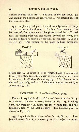
QO BENCH WORK IN WOOD.
bottom and with each other. The ends of the box, where the
end grain of the bottom and side pieces is encountered, present
the most difficulty.
154. In planing end grain, the cutting edge must be sharp
and set to take a fine shaving. If only a little material is to
be taken off, the movement of the plane should be so limited
that the cutting edge will not extend beyond the work, two
cuts being taken in opposite directions, as indicated by A and
B, Fig. 175. The motion of the plane in both directions,
Fig. IT'S "Kig.aT'G
ceases near C. If much is to be removed, and it seems best
to carry the plane the entire length of the surface, a bevel maybe made which will allow the cutting edge of the plane to leave
the work gradually, and at a little distance from the edge, as
shown by Fig. 176.
EXERCISE No. 6. BENCH-HOOK (12).
The stock required is if" X 2f" X 16" from Exercise No. 4.
It is shown with the necessary lining by Fig. 177, in which
figure the Plan, face A, represents the working-face, and the
Elevation, face B, the working-edge. The finished piece is
shown by Fig. 178.
155. Lay off the lines ab and cd <y& face B, Fig. 177. Pro-
ject ab across face A, as shown by ae, and project cd across

BENCH WORK. 97
face C (not shown), and from these, project on face D lines
similar to ab and cd, which are already located on B. Lo-
cate the point / on lines ab and cd, and also on the similar lines
of the opposite face D, measuring in each case from the work-
Scale l>/~l'
PLAN (FACE A.)
ELEVATION (FACE B.)
ing-face A, as indicated by the dimensions given. By use of a
straight-edge, draw ij and ik, and similar lines on the opposite
face.
Cut along the lines ij and ik with the rip-saw. There are
two ways of starting the saw when the material, as at k, is not
sufficient to hold the blade. First, a saw cut may be made
along the line cq, and the triangle cqk chiseled out, giving a flat
surface, cq, on which to begin ; secondly, a block of wood of
the same breadth with the work may be fastened in the vise
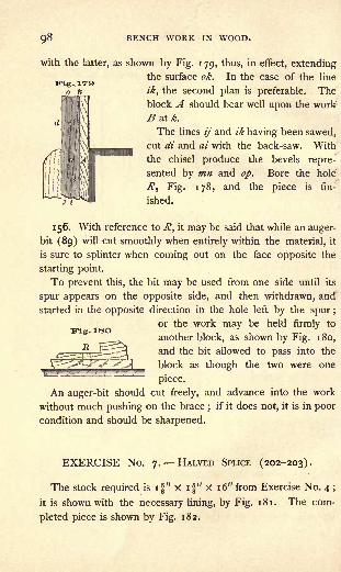
98 BENCH WORK IN WOOD.
with the latter, as shown by Fig. 1 79, thus, in effect, extendingthe surface ok. In the case of the line
ik, the second plan is preferable. Theblock A should bear well upon the work
B at*.
The lines ij and ik having been sawed,
cut di and ai with the back-saw. With
the chisel produce the bevels repre-
sented by mn and op. Bore the hole
R, Fig. 178, and the piece is fin-
ished.
156. With reference to R, it may be said that while an auger-
bit (89) will cut smoothly when entirely within the material, it
is sure to splinter when coming out on the face opposite the
starting point.
To prevent this, the bit may be used from one side until its
spur appears on the opposite side, and then withdrawn, and
started in the opposite direction in the hole left by the spur ;
or the work may be held firmly to
another block, as shown by Fig. 180,
and the bit allowed to pass into the
block as though the two were one
piece.
An auger-bit should cut freely, and advance into the work
without much pushing on the brace;
if it does not, it is in poor
condition and should be sharpened.
EXERCISE No. 7. HALVED SPLICE (202-203).
The stock required is if" X if" X 16" from Exercise No. 4 ;
it is shown with the necessary lining, by Fig. 181. The com-
pleted piece is shown by Fig. 182.

BENCH WORK. 99
157- A and B, Fig. 181, were marked as working-faces
when the piece was planed, and may be used as such in this
exercise. Midway be-
tween the two ends on
face A, locate the line
a, and from a locate b,
c, d, and e. Produce
each of these lines
across all four faces of
the piece. Set the
gauge at if" (half of
if" the width of the
piece), and from the
working-face A, gaugea line from b on face
B around the end, and
back to b on face D ;
also from line d on face
B around the opposite
end to line d on face
D. These lines are
shown on face B by
fg and ij. The joint
is made by cutting out
the rectangular pieces
bhgf and ij'lk.
158. In cutting a
splice, both pieces are
not taken from the same
face, for the reason that the gauged line maynot be exactly in the middle, and in that case m
each of the remaining parts would be more -D
than half or less than half the thickness of
Tr

100 BENCH WORK IN WOOD.
the material, and their united thickness, when put together,
as in Fig. 182, would be greater or less than the material else-
ELEVATION. FllCC R,
where. The pieces cut out, therefore, are from opposite faces.
Then if the gauge line is not in the center of the piece, that is,
if bhgf is thicker than ijlk, the smaller piece will be taken out on
one side, and the larger piece on the other;and the sum of
the two remaining parts when put together, as in Fig. 182, will
be equal to the full size of the material.
159. To cut the pieces, first run the rip-saw down the lines
gf and ij'; next, with the back-saw, cut the lines bf and Ij
'
;
next the lines c and e, being care-
ful in all of these cuts to keep the
proper side of the line (148). Finally,
cut on the line a, and try the pieces
together as in Fig. 182. If the work
has been well done, the joint will be
good. If it is not good, the faults
may be corrected. The cuts gf and
ij, if not quite to line, may be brought
to it by using the chisel as shown by Fig. 147. To facili-
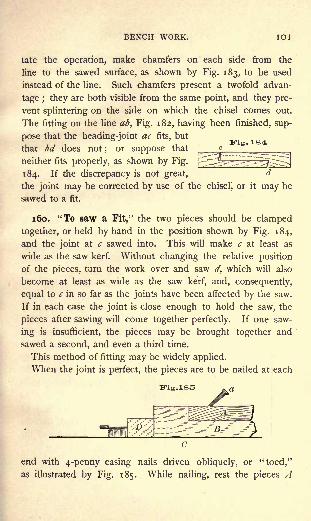
BENCH WORK. IOI
tate the operation, make chamfers on each side from the
line to the sawed surface, as shown by Fig. 183, to be used
instead of the line. Such chamfers present a twofold advan-
tage ; they are both visible from the same point, and they pre-
vent splintering on the side on which the chisel comes out.
The fitting on the line ab, Fig. 182, having been finished, sup-
pose that the heading-joint ac fits, butJ
ITig. 184that bd does not
;or suppose that c
neither fits properly, as shown by Fig.[ S^^^J
184. If the discrepancy is not great,d
the joint may be corrected by use of the chisel, or it may be
sawed to a fit.
160. "To saw a Fit," the two pieces should be clamped
together, or held by hand in the position shown by Fig. 184,
and the joint at c sawed into. This will make c at least as
wide as the saw kerf. Without changing the relative position
of the pieces, turn the work over and saw d, which will also
become at least as wide as the saw kerf, and, consequently,
equal to c in so far as the joints have been affected by the saw.
If in each case the joint is close enough to hold the saw, the
pieces after sawing will come together perfectly. If one saw-
ing is insufficient, the pieces may be brought together and
sawed a second, and even a third time.
This method of fitting may be widely applied.
When the joint is perfect, the pieces are to be nailed at each
Fig.185
end with 4-penny casing nails driven obliquely, or "toed,"
as illustrated by Fig. 185. While nailing, rest the pieces A

102 BENCH WORK IN WOOD.
B on the bench C, and, to retain them in position,
allow one to bear on
the block D, which
in turn is held by the
bench-stop. The block
protects the ends of the
work, which would be
mutilated by the bench-
stop if they were placed
in direct contact with
it.
161. Toeing Nails.
The advantage to be
derived from toeing a
nail lies in the fact that
it always" draws "
in
the direction in which
it is driven. If driven
k* as shown by a, Fig. 185,
H- it will draw A upon
p B both in a horizontal
> and in a vertical direc-
w tion, and will thus in-
sure good contact be-
tween the parts of the
joint.
The nails having been
driven and set, each of
the four sides may be
given a final smooth-
ing by a stroke of the
plane.

BENCH WORK. 103
EXERCISE No. 8. SPLAYED SPLICE.
The stock required is if'x i|"x 16", from Exercise No. 4 ;
the necessary lines are shown by Fig. 186. The finished piece
is represented by Fig. 187.
162. Let the faces A and B be the working-faces. Layoff on face A line a, and from a, the lines b, c, d, f, f, g, h, and
/, and project these lines on all four faces of the work. Set the
bevel at an angle of 45 degrees ;with its beam on A, as indi-
cated by the dotted outline, lay off on B lines dj, bk, gj, and
ik, and repeat these lines on face D. Connect points on both
B and D, forming lines which on B appear as bj and ij.The
portions marked r are to be removed.
163. To cut the joint, first use the
rip-saw on the lines bj and ij, and
afterwards the back-saw on the short
oblique lines gj and bk. The back-
saw can easily be started if, while the
piece is held in the vise, a stroke is
given in the direction a, Fig. 188,
to carry the saw into the work a distance equal to the depth

IO4 BENCH WORK IN WOOD.
of its teeth, after which it may be turned into the desired di-
rection b.
The splayed ends dj and ik may be cut with the work on
the bench-hook, Fig. 189. By following the directions given in
the previous exercise the joint may be finished, as shown by
Fig. 187.
EXERCISE No. 9. MORTISE-AND-TENON JOINT (211-215).
The stock required is if" x if" X 16", from Exercise No. 4 \
it is shown with the necessary lines by Fig. 190. The finished
piece is shown by Fig. 191.
164. Let A and B represent the two working-faces. From
one end of the piece, on face A, lay off line a, and from a, lay ofl
lines b, c, and d. Measure carefully the width of the piece on
line d, face A, and lay off one-half of the same on each side ol
the line b, and through the points thus fixed make lines e and/Project the lines a, c, and d on all four faces of the piece, and th:
lines e and / on B and D, the two faces adjoining A. Set the
gauge at ", and from face A, gauge on B the line gh and a
similar line on the opposite face D. Gauge the line if and
carry it around the end of the work to the line d on face D,
Set another gauge at i^" (" + f", the width of the mortise and
of the tenon), and gauge between the same lines as before, pro-
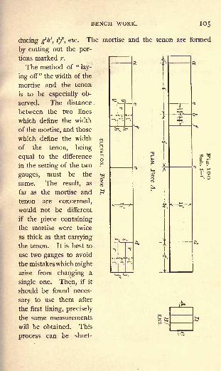
BENCH WORK. 105
ducing g>h', i'f, etc. The mortise and the
by cutting out the por-
tions marked r.
The method of "lay-
ing off" the width of the
mortise and the tenon
is to be especially ob-
served. The distance
between the two lines
which define the width
of the mortise, and those
which define the width f
|
of the tenon, being'
equal to the difference\
in the setting of the two'
gauges, must be the i
same. The result, asj
far as the mortise and !
tenon are concerned,
would not be different
if the piece containing
the mortise were twice
as thick as that carrying
the tenon. It is best to
use two gauges to avoid
the mistakes which might
arise from changing a
single one. Then, if it
should be found neces-
sary to use them after
the first lining, precisely
the same measurements
will be obtained. This
process can be short-
tenon are formed
o
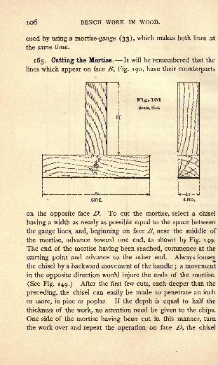
io6 BENCH WORK IN WOOD.
ened by using a mortise-gauge (33), which makes both lines at
the same time.
165. Cutting the Mortise. It will be remembered that the
lines which appear on face B, Fig. 190, have their counterparts
on the opposite face D. To cut the mortise, select a chisel
having a width as nearly as possible equal to the space between
the gauge lines, and, beginning on face B, near the middle of
the mortise, advance toward one end, as shown by Fig. 149.
The end of the mortise having been reached, commence at the
starting point and advance to the other end. Always loosen
the chisel by a backward movement of the handle;a movement
in the opposite direction would injure the ends of the mortise.
(See Fig. 149.) After the first few cuts, each deeper than the
preceding, the chisel can easily be made to penetrate an inch
or more, in pine or poplar. If the depth is equal to half the
thickness of the work, no attention need be given to the chips.
One side of the mortise having been cut in this manner, turn
the work over and repeat the operation on face D, the chisel

BENCH WORK. 107
Fig. 102
being driven down to meet the opening made from the first side.
After the cutting is finished, the chips may be dug out with a
chisel or driven through by use of a wooden plug. Never try
to drive them through by using the chisel with its cutting edge
parallel to the grain, as such use
is very likely to split the work.
The chips having been re-
moved, the truth of the mortise
may be tested by using the flat
side of the chisel as a straight-
edge, as shown by Fig. 192.
The sides of the finished mortise
should agree with the chisel, as
at a. Compare a with b. Remember that at least one-half the
thickness of the line should remain on the work.
Fig. 103
1 66. The Tenon may next be cut by using the back-saw,
both across the grain and with it. The sawing, if to line, leaves
nothing to be done except the pointing of the tenon ; this is
accomplished by a stroke of
the chisel on each side, which
makes it appear as shown by
Fig. 193. The pointing is
necessary, because a square-
ended, tight-fitting tenon, if
.driven to place, will splinter
the sides of the mortise. The
length of the tenon is suffi-
cient to make it project be-
yond the mortise a distance
more than equal to the part
pointed. After the fitting has been done, the projecting part is
cut off.
When both the mortise and tenon are finished, cut the piece
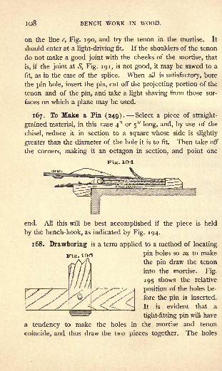
lo8 BENCH WORK IN WOOD.
on the line c, Fig. 190, and try the tenon in the mortise. It
should enter at a light-driving fit. If the shoulders of the tenon
do not make a good joint with the cheeks of the mortise, that
is, if the joint at S, Fig. 191, is not good, it may be sawed to a
fit, as in the case of the splice. When all is satisfactory, bore
the pin hole, insert the pin, cut off the projecting portion of the
tenon and of the pin, and take a light shaving from those sur-
faces on which a plane may be used.
167. To Make a Pin (249). Select a piece of straight-
grained material, in this case 4" or 5" long, and, by use of the
chisel, reduce it in section to a square whose side is slightly
greater than the diameter of the hole it is to fit. Then take off
the corners, making it an octagon in section, and point one
JTig. 1O4
Kig.
end. All this will be best accomplished if the piece is held
by the bench-hook, as indicated by Fig. 194.
1 68. Drawboring is a term applied to a method of locating
pin holes so as to make
the pin draw the tenon
into the mortise. Fig.
195 shows the relative
position of the holes be-
fore the pin is inserted.
It is evident that a
tight-fitting pin will have
a tendency to make the holes in the mortise and tenon
coincide, and thus draw the two pieces together. The holes
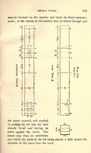
WORK. 109
tnay be located on the mortise and tenon by direct measure-
ment ;or the cheeks of the mortise may be bored through and
the tenon inserted, and marked
by putting the bit into the hole
already bored and forcing its
point against the tenon. The
tenon may then be withdrawn
and bored, the point of the bit being placed a little nearer the
shoulder of the tenon than the mark.

no BENCH WORK IN WOOD.
The practice of drawboring is not to be commended, and,
if indulged in at all, great care and discretion must be exer-
cised. In many cases, it puts a strain on the joint which is
nearly equal to its maximum resistance, and but little strength
is left to do the work for which the joint is made. Frequently,
the mortise or tenon is split and rendered practically useless.
EXERCISE No. 10.
KEYED MORTISE-AND-TENON 7011^(240-245).
The stock required is if" X if" X 16", from Exercise No. 4 ;
it is shown with the ne-
cessary lining by Fig.
196. The finished piece
is represented by Fig.
197.
T
ELEVATION.
as indicated by the dotted line/',
face A.
169. The lining dif-
fers from that of the
preceding exercise in
the following respects :
the position of the line
b is changed as indi-
cated by the dimension
figures, and the position
of lines e and f, which
extend around the piece,
is changed to corre-
spond ; the mortise is
made longer on face Bthan on face D, giv-
ing one oblique end,

BENCH WORK. Ill
As regards the tenon, the line g is added at -a distance from
d equal to the thickness of the piece on the line b, face A;
the point h is located on face A, and on the opposite face C,
and the line gh drawn on both faces. The mortise r1is to be
cut as in the preceding exercise, and one end made oblique as
indicated by the figure.
To form the tenon the portions marked r are to be removed.
First, beginning at g, cut along the oblique line gh ; then, be-
ginning at k, the two lines kj and, finally, define the shoulders
of the tenon by cutting on the line d. This order will save all
the lines as long as they are needed.
170. A study of the finished piece will show that the tenon
is inserted from the face Z>, and pushed over so that the splayed
edge of the tenon, gh, bears on the splayed end of the mortise,
;', leaving an open space at the other end of the mortise to be
filled by the key. See Fig. 197.
The key should be planed from a piece 5" or 6" long. It
should be uniform in width and nearly so in thickness, there
being but a slight taper near the end which is to be driven in
advance;
this end should be pointed like a tenon. It is best
to drive the key from the inside in the direction indicated bythe arrow, Fig. 197.
The piece is to be finished in accordance with the appear-
ance and dimensions shown by Fig. 197.
EXERCISE No. n. PLAIN DOVETAIL.
The stock required is two pieces, each-J" X 3f
" X 4",
edges jointed parallel, and one end squared. (The material
may be worked up as one piece" x 3!" X 8", which, after
being planed to width, may be cut in two with the back-saw,
thus giving the squared ends required.) The working-faces
used in preparing the material may also be used in laying off
the lines. To avoid confusion one piece will be called X and

BENCH WORK IN WOOD.
the other Y. Fig. 198 shows the lining necessary for Jf and Y
respectively. The finished joint is shown by Fig. 199.
171.
ELEVATION (FACE A.)
DEND
Lay off on all four faces of each piece," from the
squared end, the line ab, Fig. 198.
Fasten X in the vise, and on its
squared end lay off lines as gh,
Fig. 198. Remove the piece from
the vise, and with the bevel set
"i to 4" (29), project on the
faces A and C oblique lines as
ef. The portions which are to be
removed to form the mortises, are
marked r. Put the piece in the
vise again, and with the back-saw
cut down the oblique lines as ef.
With a chisel, used as in cutting
an ordinary mortise, remove the
material between the lines. If
preferred, part of it can be re-
moved by boring a hole as indi-
cated by the dotted outline. TheE.LEVATIC ,E c.)
koie ^.^ ma^e fae chiseling easier,
but in so small a piece of work it is doubtful whether there is
anything gained. The piece X having been finished, fasten Yin the vise, working-end up and working-face outward. Place
the working-face of X on the working-end of Y, as shown by
Fig. 200, taking care that the line ab on X is in the same line
with the working-face of K Holding the work in this position,
and guided by the mortises in X, scribe on the end of Y the
oblique lines as gh, Fig. 198. Remove Y from the vise, and
with the beam of the square on the working-end, project to ab
lines as ef from the extremities of the oblique lines just made.
The portions marked r and r1
are to be removed to form the

BENCH WORK.
ELEVATION (B.)
"pins." Those on the outside marked r' may be removed
entirely with the saw; those on the inside (r), partly with the
chisel, as in the case of the mortises in the piece X.
172. The joint ought to go together by light driving, and
be perfectly square on
the inside between
the working-faces. If
it is found to be satis-
factory, take it apart,
apply a light coating
of glue, and drive to-
gether again. Whenthe glue is hard, the
joint may be smoothed and squared, and
the ends of the pieces cut to the dimen-
sions shown in Fig. 199.
173. It will be seen that one part of
the joint is made, and the second part is
then made to fit the first; hence, the
proportions of the first part need not be
determined with great exactness. The skilled
bench-worker usually proceeds as follows : on
the piece X (if there are several pieces, X, he
treats them all at the same time) he lays off
the lines ab and cross-lines as gh, the latter
without measuring, and then saws obliquely
without the use of lines as ef; on Y he lays off
the lines ab and oblique lines as gh, and saws without makinglines as ef. In this way the joint is soon made, and, al-
though not perfectly symmetrical, it may be well-formed and
well-fitted.
ELEVATION (A.)

BENCH WORK IN WOOD.
ELEVATION (FACE B.)
EXERCISE No. 12. LAP, OR DRAWER, DOVETAIL.
The stock required is one piece |-" x 3f" X 4" and one
piecei'' X 3f
" X 4",
edges jointed parallel
and one end of each
squared. The finished
piece is shown by Fig.
201. It will be seen
that the piece Y does
not extend across the
full thickness of the
piece X, and, consequently, the end grain
does not ap-
pear in Eleva-
tion J3, Fig.
ELEVA-HON (FACE A.. 174. Ott Y,
Fig. 202, scribe the line ab,"
(the thickness of X) from the
working-end, and continue it
across the working-edges. Set a
gauge at f", and from the work-
ing-face A gauge the line cd on
the working-end, and extend it on
the edges until it meets the ex-
tended line ab, as shown by face
D, Fig. 202. From the working-
end of X, with the same gauge,
make the line ab on the two faces
A and C. Produce the remaining
lines on X, cut the mortises, and
lay off Y by X, as in the last
exercise.
ELEVATION (FACE A.)

BENCH WORK.
In cutting out around the pins (F), the delicacy of the work
does not demand the most delicate chisel, but one as large as
is convenient should be used. Finish the joint to the dimen-
sions given by Fig. 201.
EXERCISE No. 13. BLIND DOVETAIL.
The stock required
is two pieces, each
f' X 3f
" X 4" edges
jointed parallel and
one end squared. The
finished joint is shown
by Fig. 203. TheELEVATION (FACE B.) dovetail iswholly with-
in the square abcd> and, consequently, no
end grain shows on any face.
175. With the square, lay off on the
working-faces and two edges of each piece
of material, Fig. 204, the lines ba, at, and
ELEVATION (FACE A.I cd, dk, and from the working-face A gaugeon the ends of each piece the line ef.
Trig. 204c 6
rtt
Kig. 205Scale, S-l'
c t) JS
PLAN (FACE D.)
aPel
ELEVATION (FACE A.)

n6 BENCH WORK IN WOOD.
iri gs. 2 0(3
Scale, 3-1'
Cut both pieces as shown by Fig. 205. Taking one of the
pieces, which will be called X, space1 and lay off on the reduced
end surface lines as op, Fig. 206, using the try-square blade
as indicated by the dotted outline. Next, produce oblique
lines as gh, shown in the same
figure, and cut the mortises
marked r.
With Y in the vise apply X,
in which the mortises have al-
ready been cut, as shown by
Fig. 207, so that points may be
located along the exterior angle
e' of Y, corresponding to the
openings in X. Project these
points (shown on line e'f, Fig.
208) from the exterior angle e',
to the interior angle b {
', Fig.
207. Next apply X to Y, as
shown by Fig. 209 ;from this
position the points shown on
the line'
a'i', Fig. 208, can be
secured along the angle a'.
These points, when connected,
will give lines as gh, Y, Fig. 206.
From these lines, project on the
working-face lines as ij, down
to the line <fk'. Cut out the
portions marked r, and the dovetail is finished. It now re-
mains to make a miter-joint between the two rectangular pro-
jections on X and K Set the bevel at a miter (an angle of 45
ELEVATION (FACE Aj
1 No dimensions are given for locating the lines similar to op, X, Fig.
206. They can he found by measuring the drawing, which, as indicated bythe scale, is one-fourth the size of the piece it represents.

BENCH WORK. 117
degrees) and scribe the dotted line <?, Fig. 205, on each piece ;
then cut to line with a chisel. When the joint has been fitted,
glue, and finish to dimensions.
"Fig. 300
r
'Vvl
176. If, instead of cutting out the first and last space of Y,
one-half only is cut out, as shown by Fig. 210,
the dividing line being on a miter, and, if the
outside portions of X, m, m, Fig. 206, are cut /away to a miter to correspond, the joint will
appear as a plain miter-joint, instead of that shown by
Fig. 203.
EXERCISE No. 14. FRAME AND PANEL (246-248).
177. Fig. 211 shows a small panel door. The frame is made
up of stiles and rails, which are fastened together by mortise-and-
tenon joints ;the spaces within the frame are filled by panels.
The lower panel is simply a thin board screwed to the back of
the frame. The upper panel is composed of narrow strips, which
are inserted in a groove made in the frame for their reception.
The front of the frame, around the lower panel, is chamfered,
and around the upper panel is beaded. It is the purpose of
this exercise to construct that portion of the door included
within the rectangle abdc.
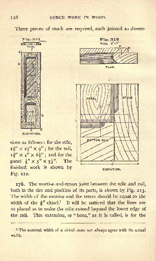
I 18 BENCH WORK IN WOOD.
Three pieces of stock are required, each jointed to dimen-
sions as follows : for the stile,
i" x 2^" x 9" ;for the rail,
11" X 4" X 6" ;and for the
panel" X 5" X si". The
finished work is shown by ELEVATION.
Fig. 212.
178. The mortise-and-tenon joint between the stile and rail,
both in the size and position of its parts, is shown by Fig. 213.
The width of the mortise and the tenon should be equal to the
width of the f" chisel.1
It will be noticed that the lines are
so placed as to make the stile extend beyond the lower edge of
the rail. This extension, or "horn," as it is called, is for the
1 The nominal width of a chisel does not always agree with its actual
width.
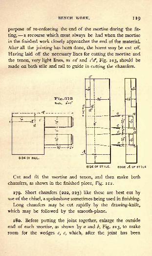
BENCH WORK. IK)
purpose of re-enforcing the end of the mortise during the fit-
ting, a recourse which must always be had when the mortise
in the finished work closely approaches the end of the material.
After all the jointing has been done, the horns may be cut off.
Having laid off the necessary lines for cutting the mortise and
the tenon, very light lines, as cd and c'd*, Fig. 213, should be
made on both stile and rail to guide in cutting the chamfers.
Scle, S-1
i- *H
SIDE OF RAIL.
SIDE OF STILE. EDGE A OF ST I LE
Cut and fit the mortise and tenon, and then make both
chamfers, as shown in the finished piece, Fig. 212.
179. Short chamfers (222, 223) like these are best cut byuse of the chisel, a spokeshave sometimes being used in finishing.
Long chamfers may be cut rapidly by the drawing-knife,
which may be followed by the smooth-plane.
180. Before putting the joint together, enlarge the outside
end of each mortise, as shown by a and b, Fig. 213, to make
room for the wedges c, c, which, after the joint has been

I2O BENCH WORK IN WOOD.
driven together, are to be dipped in glue and driven as
indicated. This method of wedging forms a very strong
joint (250, 251).
181. Round the edge of the panel on the bottom and side,
as shown by a, Fig. 212, and fasten it to the back of the
frame by two i" No. 8 screws one in the rail, and one, b,
in the stile (258).
182. In inserting screws, the outside piece (in this case the
panel) must be bored for each screw. The hole should be
sufficiently large to allow the screw to pass through easily ; and,
if the wood is hard, it must be enlarged at the top, or " coun-
terbored," to receive the head of the screw. The piece in
which the screw holds (in this case the frame), if of soft wood,need not be bored unless there is danger that it may split, in
which case a hole should be made, in diameter about two-thirds
that of the screw. The necessity for a hole in hard wood
depends largely on the proportions of the screw. A short,
large-wired screw will stand almost any service, while a long
slender one will frequently be twisted or broken under the
strain necessary to drive it into wood which is only moder-
ately hard.
Judgment must determine when the screw is driven suf-
ficiently. The head must bed well into the wood;
but
there is danger that it may be forced so far as to "strip
"
the thread, and that, as a consequence, the screw will not
hold (96, 98).
Never allow the screw-driver to slip from the slot of the
screw while the latter is being driven.
183. Brad-awls are useful in preparing the way for small
screws. The cutting edge should always be placed across the
grain so that the fibers will be cut, and not simply pressed apart
to close up again when the tool is withdrawn. The difference
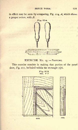
BENCH WORK. 121
in effect may be seen by comparing, Fig. 214, A, which shows
a proper action, with B.
Wig. 214.
EXERCISE No. 15. PANELING.
This exercise consists in making that portion of the panel
door, Fig. 211, included within the rectangle efgh.

122 BENCH WORK IN WOOD.
Three pieces of stock are required, each jointed to dimen-
sions as follows : stile if x 2^" x 9"; rail if X 2f x 6f ;
panel strip f X if" X 18". The completed exercise is shown
by Fig. 215.
184. In considering the joint between the stile and rail as
shown by Fig. 216, three new features will be observed; the
groove, or "plow," which is to receive the panel, as shown at
"a, Fig. 215 ;the beads f,f-, and the mitered corner cd, which
allows the parts to be plowed and beaded as shown, without
affecting the mortise-and-tenon joint.
Follow the dimensions, and line for the mortise and tenon as
in the preceding exercises, supposing the rail to be of the form
indicated by the dotted outline (?jc', Fig. 216, and the stile to
be of the form indicated by efd. This done, add the lines ec,
Fig. SIOScale, 8*-f
tj d
ELEVATION.
cd, and c'd*, by means of gauge and bevel. Cut the mortise
and the tenon, after which plow the groove a.

BENCH WORK. 123
185. No special direction can be given for using the plow
(85), except that it is to be used from the working-edge ; but
it will be safe to practice with it on a piece of waste material
before applying it to the work.
ITiS.217Scale, 3 l'
Fig. 218Scale, 3'- \
f
1 86. Next, the beads /,/, Fig. 215, are to be formed on the
inside edge of both rail and stile, that is, along the edgesmarked l>, Fig. 216. What has already been said regarding
the use of the plow, may also be said of the beading-plane
(84).
The mitered corners are now to be formed by cutting with
the back-saw to lines already made, and then the joint between
stile and rail, fitted and wedged as
in Exercise No. 14.
The frame having been made
ready, attention may be given to
the panel. The panel strip, al-
ready jointed, must be "matched"
by forming the tongue b and the
groove a, Fig. 217. This opera-
tion brings into use the \" match-
ing-planes (82), which should first
be tried on a piece of waste ma-
terial. The bead c, Fig. 217, is
to be made with a ^-" beading- "SIDE" END.
plane.
Cut the panel strip into lengths suitable for forming the
complete panel, Fig. 218, using either the bevel or the miter-
L
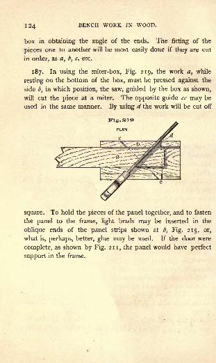
124 BENCH WORK IN WOOD.
box in obtaining the angle of the ends. The fitting of the
pieces one to another will be most easily done if they are cut
in order, as a, b, c, etc.
187. In using the miter-box, Fig. 219, the work a, while
resting on the bottom of the box, must be pressed against the
side b, in which position, the saw, guided by the box as shown,
will cut the piece at a miter. The opposite guide cc may be
used in the same manner. By using d the work will be cut off
square. To hold the pieces of the panel together, and to fasten
the panel to the frame, light brads may be inserted in the
oblique ends of the panel strips shown at b, Fig. 215, or,
what is, perhaps, better, glue may be used. If the door were
complete, as shown by Fig. 211, the panel would have perfect
support in the frame.

PART III.
ELEMENTS OF WOOD CONSTRUCTION.
TIMBER.1
188. " Timber is that portion of the woody material of trees
which is used in carpentry and joinery."" If the trunks of
timber-bearing trees are cut, they are found to be composedof concentric cylindrical layers, whose cross-
sections form rings, separated from each
other, and evidently quite distinct. These
layers [Fig. 220] are formed, one each year,
during the period of growth of the tree.
They vary in^ thickness, in density, and in
color, according to the rapidity of growth,
the length of the season, and other cir-
cumstances which may change from year to year.
"The outer portion of the trunk is called the 'sap-wood? and
it is usually lighter in color, and less strong and dense than the
interior portions, or heart-wood." The circulation of sap through the sap-wood occurs during
favorable weather. In winter it is supposed to cease, and this
period of checked circulation causes the lines of demarkation
between successive annual rings."
1Quotation marks under this heading refer to Thurston's " Materials of
Engineering," Part I.

126 BENCH WORK IN WOOD.
"The heart-wood is nearly or quite impervious to sap, its
vessels being closed up, and the wood is dense and hard." It
is usually far more durable than sap-wood." Different kinds of trees, and different individuals of the
same species, have different proportions of sap-wood. The
slower-growing trees usually contain the least."
189. "'Felling' Timber should always, if possible, be prac-
ticed at the period of maturity; if earlier, the wood will not
have acquired it greatest strength and density, and will con-
tain too great a proportion of sap-wood ;if later, the wood
will have become weakened by incipient decay.
"The oak is said to reach maturity when about TOO years of
age, and it should not be felled at less than 60." Pine timber should be cut at from 70 to 100 years of age,
and ash and elm, at from 50 to 100." The season of the year best adapted to felling timber is
either midwinter or midsummer. The months of July and
August are often selected, as at those seasons the sound trees
remain green, while the unsound trees are then turning yellow.
Healthy trees then have tops in full foliage, and the bark is
uniform in color, while unsound trees are irregularly covered
with leaves of varying color, having a rougher, and often a
loosened, bark, and decaying limbs."
After felling," the trunk should be immediately stripped of its
bark, and, when heart-wood only is wanted, the sap-wood re-
moved as soon as possible. The bark is often removed from
trees in spring, and the felling deferred till autumn or winter.
This is probably the best course to pursue, usually."
190. "Seasoning Timber is simply driving out the sap from
its pores by either natural or artificial means. This should
always be done as gradually as possible, otherwise the timber
is liable to crack or '
check,' from irregular drying." Natural or air seasoning gives the best results. The timber
WOOD CONSTRUCTION. I2/
should in all cases be squared as soon as cut, and all large logs
should be halved, or even quartered. It is then piled in the
seasoning yard in such a manner as to be protected as far as
possible from the sun and rain. It should be placed where the
air may circulate freely on all sides, not only of the pile, but of
each log ;bad ventilation is sure to cause rot. After remain-
ing thus for some months, the logs may be cut into smaller
joists, if needed in such form, or into planks and boards, and
again piled for further seasoning." For heavy work two years, and for lighter work, four years,
is sufficient time for seasoning boards;
but timber is rarely
overseasoned."
Artificial methods of seasoning by means of high tempera-
ture, are much more rapid in operation than the natural method
just described. It is not impossible, in this manner, to season
one-inch material in two days.
191. Shrinkage in timber occurs whenever it loses moisture.
In the process of seasoning, shrinkage may reduce the width
and thickness of a timber fully "eight per cent," but it has little
effect on its length. Wood cannot be so well seasoned as not
to shrink whenever the surrounding dryness is increased. It
also has a tendency to shrink after having its surface removed,
by a plane, for example. This is due to the reopening of the
pores, which in the fibers of the old surface had become closed
by contraction;in this way new passages are afforded for the
escape of moisture.
192. Swelling occurs whenever the timber absorbs moisture.
Most woods give up moisture more readily than they receive
it, and, therefore, a timber will not swell so much when trans-
ferred from a dry atmosphere to a moist one, as a similar timber
will shrink when transferred from a moist atmosphere to a dry
one, the difference in the atmospheric conditions being the
same. A slight change, however, in the amount of surrounding

128 BENCH WORK IN WOOD.
moisture is sufficient to produce a perceptible change in the
dimensions of a piece of wood. As a rule, the softer a wood is,
the more readily it shrinks and swells.
193. Warping in wood is a change of form resulting from
unequal shrinkage or swelling.
Suppose Fig. 220 to represent the end of a log. It will be
seen that, besides the lines defining the annual ring layers, there
are others extending from the center in all directions;these
are known to the botanist as medullary rays, and sometimes
to the carpenter as silver rays. In some woods, they are ver)
clearly defined;
in others, they are hardly discernible. The
medullary rays serve to bind together the annual ring layers
and are not very much shortened by shrinkage. In seasoning
the outer ends draw together, as at A and B, Fig. 221, anc
Fig. 233
produce ragged cracks, which sometimes extend from the ex-
terior to the heart-wood, as shown.
194. If a log is cut longitudinally into five pieces, the mid-
dle piece will, in shrinking (by the drawing together of the
medullary rays), become thinner at the edges than at the
center, as shown by Fig. 222. The other four pieces wil
warp as shown, the surface of each piece, which in the log was
nearest the center, becoming the convex side after shrinking.
The shrinkage of a square joist will vary according to its
position in the log relative to the heart. (See Fig. 223.) Thus,
it will be seen that, in the cross-section of a timber, changes
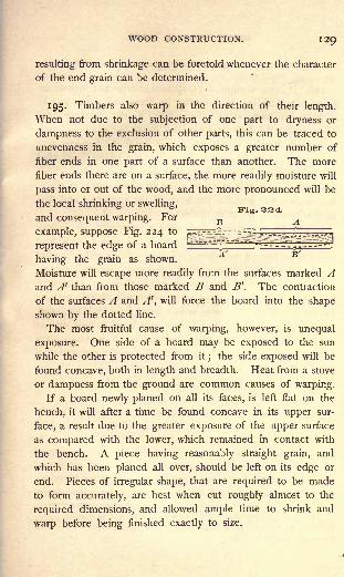
WOOD CONSTRUCTION. I2Q
resulting from shrinkage can be foretold whenever the character
of the end grain can be determined.
195. Timbers also warp in the direction of their length.
When not due to the subjection of one part to dryness or
dampness to the exclusion of other parts, this can be traced to
unevenness in the grain, which exposes a greater number of
fiber ends in one part of a surface than another. The more
fiber ends there are on a surface, the more readily moisture will
pass into or out of the wood, and the more pronounced will be
the local shrinking or swelling,
and consequent warping. For
example, suppose Fig. 224 to
represent the edge of a board
having the grain as shown.
Moisture will escape more readily from the surfaces marked Aand A' than from those marked B and B '. The contraction
of the surfaces A and A', will force the board into the shape
shown by the dotted line.
The most fruitful cause of warping, however, is unequal
exposure. One side of a board may be exposed to the sun
while the other is protected from it;
the side exposed will be
found concave, both in length and breadth. Heat from a stove
or dampness from the ground are common causes of warping.
If a board newly planed on all its faces, is left flat on the
bench, it will after a time be found concave in its upper sur-
face, a result due to the greater exposure of the upper surface
as compared with the lower, which remained in contact with
the bench. A piece having reasonably straight grain, and
which has been planed all over, should be left on its edge or
end. Pieces of irregular shape, that are required to be made
to form accurately, are best when cut roughly almost to the
required dimensions, and allowed ample time to shrink and
warp before being finished exactly to size.
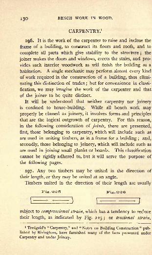
130 BENCH WORK IN WOOD.
CARPENTRY.1
196. It is the work of the carpenter to raise and inclose the
frame of a building, to construct its floors and roofs, and to
complete all parts which give stability to the structure ; the
joiner makes the doors and windows, erects the stairs, and pro-
vides such interior woodwork as will finish the building as a
habitation. A single mechanic may perform almost every kind
of work required in the construction of a building, thus elimi-
nating this distinction of trades;but for convenience in classi-
fication, we may imagine the work of the carpenter and that
of the joiner to be quite distinct.
It will be understood that neither carpentry nor joinery
is confined to house-building. While all bench work may
properly be classed as joinery, it involves forms and principles
that are the logical outgrowth of carpentry. For this reason,
in the following consideration of joints, there are presented,
first, those belonging to carpentry, which will include such as
are used in uniting timbers, as in a frame for a building ; and,
secondly, those belonging to joinery, which will include such as
are used in joining small planks or boards. This classification
cannot be rigidly adhered to, but it will serve the purpose of
the following pages.
197. Any two timbers may be united in the direction of
their length, or they may be united at an angle.
Timbers united in the direction of their length are usually
Kig.325 Fig. 22G
subject to compressional strain, which has a tendency to reduce
their length, as indicated by Fig. 225 ;or tensional strain,
1Tredgold's
"Carpentry," and " Notes on Building Construction "
pub-lished by Rivingtons, have furnished many of the facts presented under
Carpentry and under Joinery.

WOOD CONSTRUCTION.
which has a tendency to increase their length, Fig. 226;
or
cross-strain, which has a tendency to bend them, Fig. 227 ;
or to two of these strains at the same time.
198. A Timber subjected to cross-strain must always bend.
The fibers forming that surface which is convex or has a
tendency to become so (as the lower surface, A, Fig. 227)
will be subject to tensional strain, while the fibers formingthe opposite surface will be brought under compressional
strain. This is shown by Fig. 228, A representing a straight
Fig.SST Fig. 338
timber, and B the same timber bent. It follows, then, that
somewhere between the compressed surface and the ex-
tended surface there will be a line which is subject to neither
compressional nor tensional strain;such a line is called the
neutral axis of a timber, and will be located with sufficient
accuracy for the purposes of this work, if drawn midway be-
tween the upper and lower surfaces, as shown by the dotted
line CD, Fig. 228.
In the timber that has been forced into a curved form, Fig.
228, the fibers within the neutral axis are under no strain ex-
cepting that required to hold the compressed portion to the
extended portion ;but the conditions are found to change
rapidly as the examination extends to fibers more and more
remote from this axis. In other words, the strength of such
a timber increases rapidly as its depth increases. For example,if Fig. 227 represents a 2" x 4" timber (2" wide and 4" deep)
supported at B, B, and capable of sustaining 200 pounds at C,
132 BENCH WORK IN WOOD.
it can be shown that, if the depth is doubled, leaving the width
the same, by substituting a 2" X 8" timber, it will sustain four
times the original load, or 800 pounds ;while if the width is
doubled, leaving the depth the same, by substituting a 4" x 4"
timber, it will sustain only twice the original load, or 400
pounds. The law is that the strength of timbers subject to
cross-strain, varies as the width, and as the square of the
depth.1
199. Rankine has given five principles to be observed in
designing joints and fastenings. They are as follows :
1. "To cut the joints and arrange the fastenings so as to
weaken the pieces of timber that they connect as little as pos-
sible."
2. "To place each abutting surface in a joint as nearly as
possible perpendicular to the pressure which it has to transmit."
3. "To proportion the area of each surface to the pressure
which it has to bear, so that the timber may be safe against
injury under the heaviest load which occurs in practice, and
to form and fit every pair of such surfaces accurately, in order
to distribute the stress uniformly."
4. "To proportion the fastenings so that they may be of
equal strength with the pieces which they connect."
5. "To place the fastenings in each piece of timber, so that
there shall be sufficient resistance to the giving way of the joint
by the fastenings shearing or crushing their way through the
timber."
Complicated forms of joints are likely to violate Rule 3.
1 By what has been given, it will be seen that in any body of material
the portions most affected in resisting cross-strain are those lying near the
upper and lower surfaces, Fig. 227. In view of this fact, parts that are to
receive a cross-strain, especially if of iron, are, in important structures,
formed to present a large amount of material near these surfaces. A rail-
road rail or an I-beam are simple illustrations; a bridge truss is an elabo-
ration of this principle.

WOOD CONSTRUCTION. 133
JOINTS CONNECTING TIMBERS IN THE DIRECTION OF THEIR
LENGTH.
200. A Lapped Joint, shown by Fig. 229, fastened either by
straps A or bolts B, is clumsy, but very strong.
201. A Fished Joint in its simplest form is shown by Fig.
230, and is so called because of the two pieces marked A called
"fish-pieces"or "fish-plates"
fig. 23Q Fig. 23O
g
Fish-pieces may be of either wood or iron, and may be
employed to form the fished joint shown in Fig. 230, or applied
to more complicated joints to increase their strength.
When subject to compressional strain, a fished joint should
have four plates, one on each face. When subject to tensional
strain, the plates, if of iron, may be indented, A, Fig. 231 ; or,
if of hard wood, the ends may be tabled, B, Fig. 231, or keys
inserted as shown by A and B, Fig. 232. Other things being
equal, if the number of keys is doubled, the thickness of each
may be diminished one-half without reducing the strength of
the joint, since the total amount of abutting surface will remain
the same.
NOTE. The student should observe carefully the position of the lines
in the following representations of joints, so that he may clearly see the
reasons for the different methods of construction. He should first look for
the abutting surfaces, and then note their relation to the rest of the joint.
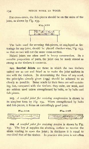
134 BENCH WORK IN WOOD.
For cross-strain, the fish-pieces should be on the sides of the
joint, as shown by Fig. 233.
3Tig. 333
The bolts used for securing fish-pieces, or employed as fas-
tenings for any joint, should be placed checker-wise, Fig. 233,
so that no two will cut the same cross-section.
Fished joints are often used in heavy construction. By a
suitable proportion of parts, the joint can be made almost as
strong as the timbers it connects.
202. Scarfed Joints are those in which the two timbers
united are so cut and fitted as to make the joint uniform in
size with the timbers. In determining the form of any scarf,
the principles already given (199) should be adhered to as
closely as possible. Some scarfs by their form are self-sustain-
ing, but, compared with the timbers they unite, are weak, and
are seldom used unless strengthened by bolts, or by bolts and
fish-pieces.
203. A scarfed joint for resisting compression is shown in
its simplest form by Fig. 234. When strengthened by bolts
and fish-pieces, it forms an exceedingly good joint.
Fig. 235
204. A scarfed joint for resisting tension is shown by Fig.
235. The key A supplies the abutting surface to receive the
strain tending to open the joint ;in thickness it is equal to
one-third that of the timber. In practice this joint is not often

WOOD CONSTRUCTION. 135
employed without fish-pieces. Fig. 236 shows a modification
of 235, which will serve excellently for tensional strain.
205. A scarfed joint for resisting cross-strain is subject
to compressional strain in its upper portion, and to tensional
strain in its lower portion (198), and must, therefore, embodyforms adapted to resisting both, as shown by Fig. 237. A
single fish-piece is usually added to the lower side of the joint.
Fig.,237
206. A scarfed joint for resisting tension and compression
may be made, as shown by Fig. 238 ; or, less complicated, as
shown by Fig. 239 ; or, more secure, as shown by Fig. 240.
Fig. S38 lTig.230
207. A scarfed joint for resisting tension and cross-strain
is sometimes made as illustrated by Fig. 241, but this form is
Fig. 240
not so good as the one shown by Fig. 233, if in the latter case
the fish-pieces are indented.

!^6 BENCH WORK IN WOOD.
JOINTS CONNECTING TIMBERS AT RIGHT ANGLES.
208. Halving, Fig. 242, forms a very simple joint, and when
well fastened, a strong one. It is frequently employed.
Beveled-halving, Fig. 243, is sometimes resorted to with the
view of allowing the load imposed upon A in the direction of
the arrow, to hold the joint together. Under ordinary circum-
stances, this joint is likely to prove weak, because of a lack of
material at the shoulder near the letter A.
3Tig. 244
Fig. 343
iris.243
1J
209. Notching. In placing several timbers upon another
which is to support them, in the manner represented by Fig.
244, it is usually desired that the tops of the supported timbers
be uniform in height. This would not be accomplished by
simply placing them in a row, because timbers of the same
nominal size vary in their breadth and depth. The ends of
the deeper ones must therefore be cut or "notched," as shown
by Fig. 244, to make them agree in depth with the lightest
timber of all. Properly speaking, this is a preparation for the
bearing of one timber on another, and not a joint ;but if the
end of the supported timber is allowed to project, as repre-
sented by Fig. 245, a true joint is made.
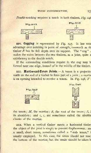
WOOD CONSTRUCTION. 13
Double-notching requires a notch in both timbers, Fig. 24^
210. Cogging is represented by Fig. 247. It has som
advantage over notching in point of strength, inasmuch as th
timber B has its full depth over its support. The "cog
"^
makes the union between the two timbers, as a joint, quite a
satisfactory as the double notch.
If the surrounding conditions require it, the cog may b
formed near one edge, instead of in the middle of the timber.
211. Mortise-and-Tenon Joints. A tenon is a projectio
made on the end of a timber to form part of a joint ;a mortis
is an opening intended to receive a tenon. In Fig. 248, T \
. 248
Fig. 347
the tenon; M, the mortise
; R, the root of the tenon; S, *!
its shoulders;
and c, c, are sometimes called the abuttin
cheeks of the mortise.
212. When a vertical timber meets a horizontal timbei
the object of the joint is simply to prevent displacement ;am
a small, short tenon, sometimes called a "stub tenon," i
usually employed. In this case, the tenon should not reac
the bottom of the mortise, but the strain should be taken b
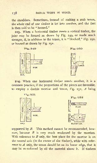
138 BENCH WORK IN WOOD.
the shoulders. Sometimes, instead of making a stub tenon,
the whole end of one timber is let into another, and the first
is then said to be " housed."
213. When a horizontal timber meets a vertical timber, the
joint may be formed as shown by Fig. 249, or made much
stronger, if, in addition to the tenon, it is"blocked," Fig. 250,
or housed as shown by Fig. 251.
Fig. 24O
214. When one horizontal timber meets another, it is a
common practice, if the proportions of the pieces are favorable,
to employ a double mortise and -tenon, Fig. 252, A being
Fig. 251
1IT-IS.
END.
supported by B. This method cannot be recommended, how-
ever, because B is very much weakened by the mortises.
With reference to B only, the best place for the mortise is on
the neutral axis (in the center of the timber), while with refer-
ence to A only, the tenon should be on its lower edge, that it
may be re-enforced by all the material above it. If timbers
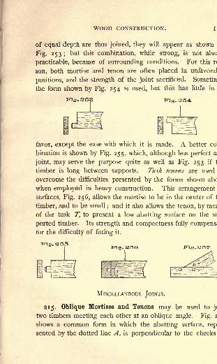
WOOD CONSTRUCTION.
of equal depth are thus joined, they will appear as shown
Fig- 253 '>but this combination, while strong, is not alw;
practicable, because of surrounding conditions. For this r<
son, both mortise and tenon are often placed in unfavoral
positions, and the strength of the joint sacrificed. Sometin
the form shown by Fig. 254 is used, but this has little in
Fig.SSf
favor, except the ease with which it is made. A better co
bination is shown by Fig. 255, which, although less perfect a
joint, may serve the purpose quite as well as Fig. 253 if 1
timber is long between supports. Tusk tenons are used
overcome the difficulties presented by the forms shown abc
when employed in heavy construction. This arrangement
surfaces, Fig. 256, allows the mortise to be in the center of 1
timber, and to be small;and it also allows the tenon, by me;
of the tusk T, to present a low abutting surface on the si
ported timber. Its strength and compactness fully compens;
for the difficulty of fitting it.
Fig.SSG
MlSCELLANEOUS JOINTS.
215. Oblique Mortises and Tenons may be used toj<
two timbers meeting each other at an oblique angle. Fig. 2
shows a common form in which the abutting surface, rep
sented by the dotted line A, is perpendicular to the cheeks

140 BENCH WORK IN WOOD.
the mortise, and the strain transmitted in the direction of the
arrow, is divided between the surfaces represented by the
dotted line A and the full line B. A bearing along the latter
line becomes unreliable when the timbers shrink, or when, bythe settling of connected parts, the surfaces change their rela-
tive position. For this reason it is better to depend mainly on
the line A, which is less affected by the causes mentioned. To
take the strain wholly, A should be at right angles to the length
of the tenon-bearing timber, Fig. 258. This, however, while
apparently a well-formed joint, is not a strong one, for the
tenon, which is usually equal to but one-third the width of
the timber, must alone receive the thrust. To relieve the tenon
by increasing the area of the abutting surface, the end of Amay be housed as shown by Fig. 259, or the joint may be
strengthened by bolts or straps.
The mortise for the joint shown by Fig. 258 is usually madeof the outline abc, and the triangle a!be is not filled. This is
done because it is easier to cut down the line be than the line
a'c. There seems to be no objection to this practice.
Fig. 260
216. A Bridle-Joint is represented by Fig. 260. It pos-sesses the advantage of having its parts so exposed that anyinaccuracy in the fit is always apparent. An oblique form of

WOOD CONSTRUCTION. 14!
bridle-joint, Fig. 261, is certainly worthy of study. The widtf
of the bridle, B, Fig. 260, should not exceed one-fifth th<
width of the timber.
217. A Tie-Joint is shown by Fig. 262. The timber A ii
prevented from falling away in the direction indicated by th<
arrow, by the insertion of the tie B. The joint illustrated b]
Fig. 197 may be made to serve the same purpose.
END. SIDE.
Fig. 263
1
218. A Chase-Mortise is a mortise elongated as shown b;
Fig. 263. Its purpose is to admit a cross-timber betweei
two timbers already fixed. When the cross-timber is in place
that portion of the mortise which is unoccupied may be filled
and the joint thus made secure.
JOINERY.
219. The work of the joiner, unlike that of the carpenter, ii
usually where it must bear the test of close examination. It is
therefore, necessary that the several pieces of which a whol<
work is formed, be united by joints that are neat in appearanceor so made as to be hidden from sight. Such joints must b<
strong even where there is apparently but little strain uporthem. Otherwise, the parts are likely to become loose frorr
shrinking and swelling, and to expose unsightly seams.
Some of the joints already described, while particularly adaptec
to uniting timbers in carpentry, may under given conditions b<
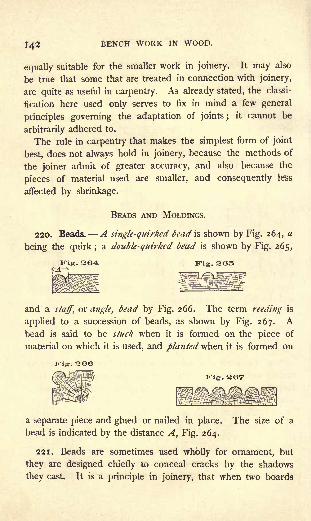
142 BENCH WORK IN WOOD.
equally suitable for the smaller work in joinery. It may also
be true that some that are treated in connection with joinery,
are quite as useful in carpentry. As already stated, the classi-
fication here used only serves to fix in mind a few general
principles governing the adaptation of joints ;it cannot be
arbitrarily adhered to.
The rule in carpentry that makes the simplest form of joint
best, does not always hold in joinery, because the methods of
the joiner admit of greater accuracy, and also because the
pieces of material used are smaller, and consequently le'ss
affected by shrinkage.
BEADS AND MOLDINGS.
220. Beads. A single-quirked bead is shown by Fig. 264, a
being the quirk; a double-quirked bead is shown by Fig. 265,
Fig. 265
and a staff, or angle, bead by Fig. 266. The term reeding is
applied to a succession of beads, as shown by Fig. 267. Abead is said to be stuck when it is formed on the piece of
material on which it is used, and planted when it is formed on
Trig. 366
a separate piece and glued or nailed in place. The size of a
bead is indicated by the distance A, Fig. 264.
221. Beads are sometimes used wholly for ornament, but
they are designed chiefly to conceal cracks by the shadows
they cast. It is a principle in joinery, that when two boards

WOOD CONSTRUCTION.
are to be joined they must be made as one complete board,
with the joint so concealed that no crack is left, either when
first made or after shrinkage ;or there should be a very decided
crack, which will appear to have been made intentionally. The
first kind of joint is made by means of glue ; but, as the boards
forming a surface of considerable width must have some free-
dom of movement on account of shrinking and swelling tenden-
cies, it follows that when large surfaces are to be covered, glued
joints cannot be used. Under such circumstances, it is found
best to make no attempt at a close joint, but to allow the
F-ig. 368 P'ig. 2O9
pieces to shrink and swell as they may, and depend uponbeads to conceal the cracks. Thus the joint shown by Fig. 268
would seem to have been intended for a close fit;but since it
is not, the opening is allowed to remain, and a bead applied,
as shown by Fig. 269. The crack is thus converted into a quirk
of a bead, and is not noticeable except on close inspection.
222. A chamfer is a narrow surface produced, usually, at
an angle of forty-five degrees with two other surfaces. Like
the bead, it may be used for ornament, or for disguising cracks
as shown by Fig. 270.
223. A stop chamfer is one which does not extend the full
length of the piece on which it is formed. See A, Fig. 212.

144 BENCH WORK IN WOOD.
224. Moldings, while of the same character with beads, are
larger and often much more complex in form. They may be
stuck or planted. Among the most simple forms is the ogee,
Fig. 271, which is frequently used as a finish for the edge of a
projecting board a table top, for example.
225. A round nose, Fig. 272, is, perhaps, the simplest of
all, and is especially useful where a projecting board is subject
to usage severe enough to destroy sharp angles or small details,
as is the " tread"of a stair.
226. From a few simple forms, of which the two shown are
types, have sprung the variety of styles, which, for the most
part, have no designation but the number given them by the
manufacturer. While most of them may be stuck, as is the
ogee, Fig. 271, and the common forms shown by Fig. 273,
they are generally planted. Fig. 274 shows a molding at A,
planted on a plain surface;
at B, one planted in an angle, and
at C, a rabbeted (bolection) molding which overlaps one of
the pieces forming the angle.
A fillet^ is a light strip of material used in a joint as a
fastening, or, in connection with beads and moldings, as a
means of ornamentation.
227. In joining boards, use is frequently made of some outside
support, which, though not considered a part of the joint, is
1Fillet, or thread.
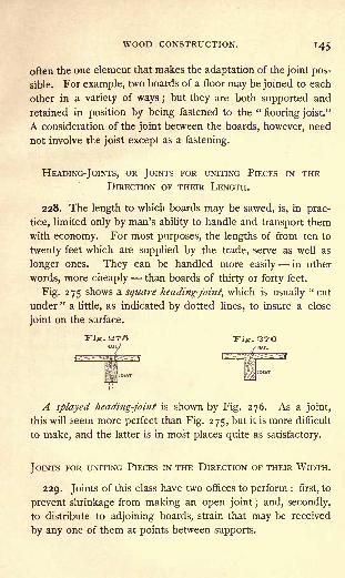
WOOD CONSTRUCTION. 145
often the one element that makes the adaptation of the joint pos-
sible. For example, two boards of a floor may be joined to each
other in a variety of ways ;but they are both supported and
retained in position by being fastened to the "flooring joist."
A consideration of the joint between the boards, however, need
not involve the joist except as a fastening.
HEADING-JOINTS, OR JOINTS FOR UNITING PIECES IN THE
DIRECTION OF THEIR LENGTH.
228. The length to which boards may be sawed, is, in prac-
tice, limited only by man's ability to handle and transport them
with economy. For most purposes, the lengths of from ten to
twenty feet which are supplied by the trade, serve as well as
longer ones. They can be handled more easily in other
words, more cheaply than boards of thirty or forty feet.
Fig. 275 shows a square heading-joint, which is usually "cut
under " a little, as indicated by dotted lines, to insure a close
joint on the surface.
ITig. 275 wig, z>7&
A splayed heading-joint is shown by Fig. 276. As a joint,
this will seem more perfect than Fig. 275, but it is more difficult
to make, and the latter is in most places quite as satisfactory.
JOINTS FOR UNITING PIECES IN THE DIRECTION OF THEIR WIDTH.
229. Joints of this class have two offices to perform : first, to
prevent shrinkage from making an open joint ; and, secondly,
to distribute to adjoining boards, strain that may be received
by any one of them at points between supports.

1^6 BENCH WORK IN WOOD.
230. Fig. 277 shows at A a plain butt-joint, which has no
provision against opening, and in which the boards do not sup-
port each other ;it is, really, no joint at all. The same figure
shows at B, C, and D, respectively, a filleted joint, a rabbeted
joint, and a matched joint. Any of these may be beaded as
shown by Fig. 269. The marring of the surface by nail heads
may be prevented by "secret nailing," which is shown in
Fig. 277.Fig. 37TB C
', .'
JOIST
Joints of this class which have no support outside of them-
selves, must be held by glue.
231. A Glued Butt-joint, shown by Fig. 278, if well made,
will be quite as strong in the softer woods as a glued matched
or a glued filleted joint. It is difficult, however, especially if the
boards are long, to keep the two pieces forming the plain joint
in proper position while the glue is setting. Even if they are
clamped, they are almost sure to slip, so that when the joint has
finally become firm, the boards may have assumed a position
similar to that shown, Fig. 278. The fillet, and the tongue and
j Fig. 3T9
groove (B and D, Fig. 277) are useful in keeping the parts in
place until the glue has hardened. Dowels may be used for
the same purpose, Fig. 279. If they are placed at short inter-
vals, and are well fitted, they will add strength to the joint.
232. Cleating. A cleat is a piece of material fastened
across the width of a board to prevent its warping ;if the sur-
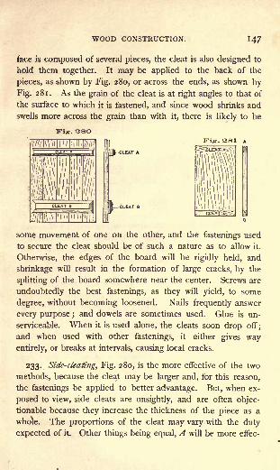
WOOD CONSTRUCTION.
face is composed of several pieces, the cleat is also designed to
hold them together. It may be applied to the back of the
pieces, as shown by Fig. 280, or across the ends, as shown by
Fig. 281. As the grain of the cleat is at right angles to that of
the surface to which it is fastened, and since wood shrinks and
swells more across the grain than with it, there is likely to be
Fig. 28OFig. 381
some movement of one on the other, and the fastenings used
to secure the cleat should be of such a nature as to allow it.
Otherwise, the edges of the board will be rigidly held, and
shrinkage will result in the formation of large cracks, by the
splitting of the board somewhere near the center. Screws are
undoubtedly the best fastenings, as they will yield, to some
degree, without becoming loosened. Nails frequently answer
every purpose ;and dowels are sometimes used. Glue is un-
serviceable. When it is used alone, the cleats soon drop off;
and when used with other fastenings, it either gives way
entirely, or breaks at intervals, causing local cracks.
233. Side-cleating, Fig. 280, is the more effective of the two
methods, because the cleat may be larger and, for this reason,
the fastenings be applied to better advantage. But, when ex-
posed to view, side cleats are unsightly, and are often objec-
tionable because they increase the thickness of the piece as a
whole. The proportions of the cleat may vary with the duty
expected of it. Other things being equal, A will be more effec-

148 BENCH WORK IN WOOD.
tive than B. It is more difficult, however, to put screws or
other fastenings through A than through B'
; either may be
fastened by screws inserted from the face of the board.
234. End cleats are neat in appearance, and, when decided
warping tendencies are not to be overcome, do good service.
To supplement the fastenings, a narrow tongue may be formedon the board to fit a corresponding groove in the cleat, as
shown in connection with B, Fig. 281.
235. If only one surface of a cleated board is to be madeuse of, a drawing board, for example,
the strain on the cleat may be les-
sened by a succession of saw cuts on the
lower side, extending the length of the
board, as shown by Fig. 282. By this
means, the warping tendency of a seven-
SecttonA.B.eigntns -inch board may be reduced to
that of a quarter-inch, or even a one-
eighth-inch board.
JOINTS FOR UNITING PIECES AT RIGHT ANGLES.
236. Butt-Joints. A plain joint of this kind is representedby Fig. 283. The joint may be concealed by a bead as indicated by dotted lines
; and, when the material is thick and it isdesirable to prevent an exposure of end grain as much as possi-ble, the joint may be modified, as shown by Fig. 284 Thistorm also may be beaded. When great strength is demanded,
285
a housed joint may be made, Fig. 285. The sides and end's oftroughs which are required to be
water-tight, are frequently

WOOD CONSTRUCTION. 149
made in this way. If there can be no projection, as A, Fig.
285, this joint may be modified as shown by Fig. 286, but it
will lose in strength.
237. Miter-Joint. Fig. 287 shows a plain miter-joint. Its
sole recommendation lies in the fact that it exposes no end
grain, for, from a mechanical point of view, it is weak and
faulty : weak, because difficult to fasten, and faulty, because, as
the two pieces forming the joint shrink, each will become
narrower on the lines A, A, and produce the change of form
shown by the dotted lines B and B'. As a result of this change,
either the angle C between the two pieces must become smaller,
or the joint must open, forming a wide crack on the inside,
which is represented by the triangle BDB'.
'Miter-joints between two pieces of different thickness are
Fig. 287 Fig. 288 Fig. 289
made in the form illustrated by Fig. 288. Occasionally this is
used when the pieces are of the same thickness, Fig. 289 ;for
while it has the advantages of the plain miter-joint, it is stronger
and less affected by shrinkage.
Fig. QOO Fig. 201
238. Glue, and brads or nails, the usual fastenings for miter-
joints, may be supplemented by a fillet inserted as shown by
A, Fig. 290, or by small pieces inserted in saw cuts which are
made across the angle of the joint,as shown by A, Fig. 291.
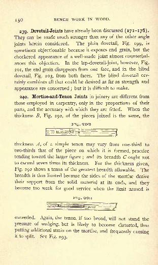
j^O BENCH WORK IN WOOD.
239. Dovetail-Joints have already been discussed (171-176).
They can be made much stronger than any of the other angle
joints herein considered. The plain dovetail, Fig. 199, is
sometimes objectionable because it exposes end grain, but the
checkered appearance of a well-made joint almost counterbal-
ances this objection. In the lap-dovetail-joint, however, Fig.
201, the end grain disappears from one face, and in the blind
dovetail, Fig. 203, from both faces. The blind dovetail cer-
tainly combines all that could be desired as far as strength and
appearance are concerned ; but it is difficult to make.
240. Mortise-and-Tenon Joints in joinery are different from
those employed in carpentry, only in the proportions of their
parts, and the accuracy with which they are fitted. When the
thickness B, Fig. 292, of the pieces joined is the same, the
Fig. 203
thickness A, of a simple tenon may vary from one-third to
two-thirds that of the piece on which it is formed, practice
tending toward the larger figure ;and its breadth C ought not
to exceed seven times its thickness. For the thickness given,
Fig. 292 shows a tenon of the greatest breadth allowable. Thebreadth is thus limited because the sides of the mortise derive
their support from the solid material at its ends, and theybecome too weak for good service when the limit named is
Fig. 2O3
exceeded. Again, the tenon, if too broad, will not stand the
pressure of wedging, but is likely to become distorted, thus
putting additional strain on the mortise, and frequently causingit to split. See Fig. 293.

WOOD CONSTRUCTION.
241. When the piece on which the tenon is to be formed is
very broad, a single tenon, if employed, leaves wide shoulders,
AB, Fig. 294. These are open to objection, because of the
tendency of the tenon piece to warp so that its surface at
D will not agree with the surface of the piece it joins, at C.
Under such circumstances a double tenon, Fig. 295, may be
used. This will give the support that is needed, and will not
violate the principle laid down in 240. Double tenons, how-
ever, while they obviate one difficulty introduce another. The
tenons are unyielding, and, if the piece is very wide, its shrink-
age is likely to produce a crack between them, as denoted bythe dotted lines A, Fig. 295.
Fig. 394 Fig. 295
242. Haunching is a device by which the tenon proper is
supplemented by very short tenons, or "haunches," as indicated
by the dotted outline, Fig. 296. The entire end of the tenon
piece is thus inserted in the mortise piece, and prevented from
warping ;the danger of its splitting from shrinkage is not in-
creased. If the piece shown by Fig. 294 were haunched, the
imperfection it illustrates would be removed.
Fig. 396
243. Four tenons may be used in a single joint when the
pieces to be united are very thick and wide, Fig. 297. Bytheir use the parts are made small enough to prevent shrinkage
from producing a bad joint.

J52 BENCH WORK IN WOOD.
244. In forming a joint at the extremity of the mortise piece,
a single tenon, if employed, must be cut away at one side, as
shown by Fig. 298. Such a joint may be haunched, Fig. 299,
or if the pieces are sufficiently wide, two tenons may be used,
Fig. 213.
. 308 Fig. 2QQ
245. Mortise-and-tenon joints in joinery are capable of all
the modifications of form which they are made to assume in
carpentry. They may be housed, for example, or made in any
of the oblique forms.
PANELING.
246. A Panel is a board, or a combination of boards, em-
ployed to fill an opening within a frame. Thus, in Fig. 300 the
pieces F constitute the frame, and the pieces A, B, C, and Dare panels. The primary purpose of this arrangement is to
give an extended surface of wood so constructed that the
pieces of which it is made shall be well and neatly fastened,
and, at the same time, the dimensions and the general appear-
ance of the whole, be unaffected by shrinking or swelling. Toenhance the attractiveness of the surface, both frame and panel
are frequently embellished, sometimes so richly that we lose
sight of the mechanical necessity of the panel, and come to
regard it as a means of decoration.
247. The Frame taken by itself is, in general, made up of
vertical and horizontal pieces united by mortise-and-tenon
joints. Vertical pieces extending the full length of any frame

WOOD CONSTRUCTION.
Kig. 300
153

154 BENCH WORK IN WOOD.
are called "stiles," and horizontal pieces, "rails." Each of
these parts should be as narrow as is consistent with the degree
of strength required. The width of a rail should never be more
than twice that of the stile, which, as a rule, should not exceed
four and a half inches. A consideration of Fig. 300 will show
that, although the door is three or more feet wide, the only sur-
faces whose shrinkage can affect the width are the two 4^-inch
stiles. Large surfaces are covered, not by increasing the size
of the parts, but by increasing their number.
The fillet e is inserted to cover the end of the tenons, which
would otherwise show on the edge of the door.
248. The panel may be either fastened to the back of the
frame, or inserted in a groove, or "plow," made in the frame
to receive it. In either case, provision must be made for
shrinking and swelling. When fastened to the back, screws
are usually found to make a sufficiently yielding joint. Whenfitted into the frame, no fastening is needed beyond that de-
rived from its position. It must fit loosely enough to draw out
on shrinking, but not so loosely as to rattle.
In Fig. 300, A is a plain panel screwed to the back of the
frame, and the frame about it is stop-chamfered. This is, prob-
ably, the simplest combination of frame and panel. In com-mon with all panels fastened in this way, it is best adapted to
work that is to be seen from one side only, as a closet door,or the permanent lining of a room.
B shows a plain panel fastened to the back of a frame whichis ornamented by a molding.C differs from B only in being let into the frame instead of
being screwed to the back. The reverse face c may be orna-mented by a molding in the same manner as C, or by achamfer.
D shows a raised panel embellished by a rabbeted molding.The reverse face d is a plain raised panel.

WOOD CONSTRUCTION. 155
A panel and frame may be plain on one side and orna-
mented on the other, the ornamentation on one side may differ
from that on the other, or the sides may be similar;and any
form of embellishment that may properly be applied to board
surfaces, may be used in connection with this work.
FASTENINGS.
249. Pins are employed principally as a means of holding
tenons in mortises. In carpentry one pin, generally, is used in
each joint, its diameter varying from one-sixth to one-fourth the
width of the tenon. It is commonly placed at a distance from
the abutting cheeks of the mortise, equal to one-third the
length of the tenon. But to secure the maximum strength of
the joint, its exact location in any particular case must be fixed
with reference to the character of the material, and also to the
relative thickness of the tenon and the cheeks of the mortise.
In joinery, it is found best to use two or more pins, and, what-
ever the proportions of the joint may be, these rarely exceed
three-eighths of an inch in diameter. They are inserted very
near the abutting cheeks of the mortise, so that that part of
the mortise between them and the shoulder of the tenon, will
not shrink enough to make an open joint.
Square pins are better than round ones, but the latter are
more easily fitted and, therefore, more used.
Drawboring has already been described (168).
250. Wedges. The most common use of wedges is illus-
trated by Fig. 213 in connection with Exercise No. 14, which
requires wedges to be dipped in glue, and driven between the
tenon and the ends of the mortise. Wedges are also driven
in saw cuts made in the end of the tenon for the purpose of
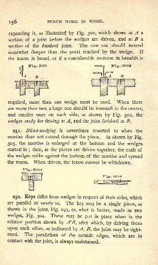
56 BENCH WORK IN WOOD.
expanding it, as illustrated by Fig. 301, which shows at A a
section of a joint before the wedges are driven, and at B a
section of the finished joint. The saw cut should extend
somewhat deeper than the point reached by the wedge. If
the tenon is broad, or if a considerable increase in breadth is
Fig. 301 Kig. 302
required, more than one wedge must be used. When there
are more than two, a large one should be inserted in the center,
and smaller ones on each side, as shown by Fig. 302, the
wedges ready for driving at A, and the joint finished at B.
251. Blind-wedging is sometimes resorted to when the
mortise does not extend through the piece. As shown by Fig.
303, the mortise is enlarged at the bottom and the wedgesstarted in
; then, as the pieces are driven together, the ends of
the wedges strike against the bottom of the mortise and spreadthe tenon. When driven, the tenon cannot be withdrawn.
252. Keys differ from wedges in respect of their sides, whichare parallel or nearly so. The key may be a single piece, as
shown in the joint, Fig. 197, or, what is better, made as two
wedges, Fig. 304. These may be put in place when in the
relative position shown by A'B, after which, by driving them
upon each other, as indicated by A, B, the joint may be tight-ened. The parallelism of the outside edges, which are in
contact with the joint, is always maintained.
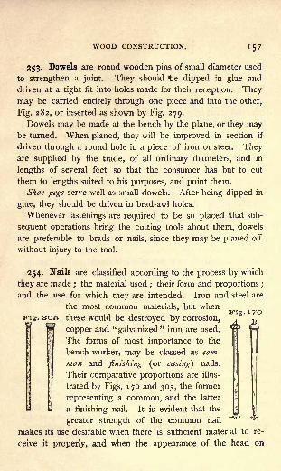
WOOD CONSTRUCTION. 157
253. Dowels are round wooden pins of small diameter used
to strengthen a joint. They should ^>e dipped in glue and
driven at a tight fit into holes made for their reception. They
may be carried entirely through one piece and into the other,
Fig. 282, or inserted as shown by Fig. 279.
Dowels may be made at the bench by the plane, or they maybe turned. When planed, they will be improved in section if
driven through a round hole in a piece of iron or steei. Theyare supplied by the trade, of all ordinary diameters, and in
lengths of several feet, so that the consumer has but to cut
them to lengths suited to his purposes, and point them.
Shoe pegs serve well as small dowels. After being dipped in
glue, they should be driven in brad-awl holes.
Whenever fastenings are required to be so placed that sub-
sequent operations bring the cutting tools about them, dowels
are preferable to brads or nails, since they may be planed off
without injury to the tool.
254. Nails are classified according to the process by which
they are made; the material used
;their form and proportions ;
and the use for which they are intended. Iron and steel are
the most common materials, but whenJTig. 17O305 these would be destroyed by corrosion, A B
copper and "galvanized"
iron are used.
The forms of most importance to the
bench-worker, may be classed as com-
mon and finishing (or casing) nails.
Their comparative proportions are illus-
trated by Figs. 170 and 305, the former
representing a common, and the latter
a finishing nail. It is evident that the
greater strength of the common nail
makes its use desirable when there is sufficient material to re-
ceive it properly, and when the appearance of the head on

158 BENCH WORK IN WOOD.
the surface is not objectionable. The finishing nail may be
used in more delicate material, and makes a smaller scar on
the work.
Cut nails are so called because, in the process of manufacture,
each nail is cut from a plate of metal. The plate has a width
equal to the length of the nail, and a thickness equal to its
breadth. Generally speaking, all nails of the form shown by
Figs. 1 70 and 305 are cut.
Wrought, as distinguished from cut nails, are those which
without breaking will bend sufficiently for clinching. As the
term suggests, such nails were formerly wrought under the
hammer, it being impossible to obtain the requisite quality by
machinery ;and they were so made long after common nails
had ceased to be made by hand. In later years, however,
wrought nails have in reality been cut, but from better material
and by more perfect processes than those which have been
technically called cut nails.
Steel cut nails are now generally introduced in this country,
and will in time take the place not only of the iron cut, but also
. ace of the s -called wrought nails; for, while less ex-
pensive than the former, they are equal in quality
to the latter.
Wire nails, Fig. 306, are at this time cominginto general use. Their strength and tenacity are
unequaled. They are made from drawn wire in
sizes varying from that of the smallest brad to
that of the largest spike.
255. The length of nails is indicated by numbers prefixedto the word "
penny," as 6-penny, 8-penny, terms 1 which are
1 It has been suggested that they once indicated the value or price of agiven number of nails, 6-penny nails being sold at six pence per hundred,and 8-penny nails for eight pence per hundred. Another explanation is
that penny, as here used, is a corruption of pound, 6-penny meaning that
WOOD CONSTRUCTION. 159
now used arbitrarily, though, originally, they were doubtless
significant.
The length of nails of ordinary sizes is given as follows :
256. Brads are small finishing nails, in form similar to the
nail shown by Fig. 305, the smaller ones being thicker, and the
larger ones more slender. Their size is expressed in inches
and fractions of an inch, and ranges from one-fourth of an inch
to two inches.
257. Tacks are useless for fastening pieces of wood to each
other, but are indispensable when lighter material, like cloth or
leather, is to be fastened to wood. They vary in form and size
with the particular use for which they are intended. Their size
is expressed by a number prefixed to the word "ounce." 1 The
length of the more common sizes varies as follows :
A i-ounce tack is three-sixteenths of nn inch long.
a thousand nails weighed six pounds; 8-penny, that a thousand weighed
eight pounds, and so on.
J This expression may have once represented the weight of 1000 tacks;
for example, 1000 tacks T3S"
long, weighed one ounce, and were, therefore,
called " one-ounce "tacks.

I6O BENCH WORK IN WOOD.
258. Common Screws are either bright or blued, steel or
brass, round-headed or flat-headed.
Bright screws are finished by polishing. When blued, the
luster of the polish has been taken off by heat or an acid, and
a deep blue finish produced. Blued screws will not rust so
easily as bright screws, and in most work they look better
considerations which apply with still greater force to the use of
brass as a material instead of steel.
Flat-headed screws, shown by Fig. 124, are the most com-
mon. When used on finished surfaces, the heads should be
sunk below the general level and the hole above them filled.
When this is not convenient, round heads, which in the finished
work will appear above the surface, are frequently employed.The size of screws is indicated by their length in inches or
fractions of an inch, and by the diameter of the wire forming
the body ;this diameter is expressed by a number which refers
to a " standard screw gauge." The sizes of the screw gauge
range from No. o, which represents a diameter of a little less
than a sixteenth of an inch, to No. 30, which represents a
diameter somewhat greater than seven-sixteenths of an inch.
The size of a screw two inches long and a quarter of an inch
in diameter would be written 2" X No. 15.
259. Glue is chiefly of two kinds, which are known as animal,and fish glue. Animal glue is a product obtained from the
refuse of tanneries (bone, horn, hoofs, and bits of hide), which
gives up the glutinous matter it contains when boiled under
pressure. Fish glue is extracted from the spawn and entrails of
fish. As prepared for the market, both are generally in the
form of cakes, varying in thickness from an eighth of an inchto very thin chips, according to the quality and character of the
glue. For bench work, these are dissolved in water, and the
mixture applied hot. For convenience in dissolving the glue, a
glue-pot is used, which is an arrangement of two vessels, one

WOOD CONSTRUCTION. l6l
within another, the inner being for glue, the outer for water.
Heat is communicated in any convenient way to the water, and
the water in turn heats the glue. The use of the vessel of
water is to prevent the glue from burning.
Gluing. When ready for use, the glue should be hot and
of the consistency of thin sirup. It must be applied with a
brush, in a thin, uniform coating to both surfaces that are to
be joined. Too much glue will prevent the pieces from coming
together in the joint. The application should be made as
quickly as possible because the glue begins to cool and set as
soon as it is taken from the pot; it will set less quickly if
the pieces to be glued are warmed. After the pieces have
been put together, they should be rubbed to squeeze out the
surplus glue, and finally clamped in place and allowed to remain
until dry at least twelve hours.
Liquid glues are supplied by the trade. They require no
heating and are, therefore, always ready for use.
When end grain is to be glued, it must first be sized, that is,
coated with thin glue, in order to fill the pores of the wood,
and allowed to dry before the joint is made. Otherwise, the
glue that is put into the joint is drawn off into the grain and
becomes useless as a fastening.

CORRIGENDA.
PAGE 18, Article 30, second line; instead of "square" read gauge ;
and in the same article, instead of Fig. 40, use Fig. 40 A, which is pre-
sented herewith.
-1- _____U
PAGE 50, second line ; omit " as Imk, Fig. 146."
PAGE 83, last line of first paragraph; instead of " c to d" read c to a.
PAGE 114, Fig. 201; instead of letters "X" read Y, and instead of
the letters "Y" read X; also in the text, eighth line, instead of " F"
read X, and in the eleventh line, instead of " X" read Y.
PAGE 150, Article 240, sixth line; instead of " two-thirds " read one-
half.

BOOKS ON ENGLISH LITERATURE.
Allen. .
Arnold .
BancroftBrowne
Reader's Guide to English History .
English Literature .... . .$-25. . 1.50A Method of English Composition 50
Shakespere Versification 25Fulton & Trueblood: Choice Readings ... ... 1.50
Chart Illustrating Principles of Vocal Expression, 2.00
Genung . . Practical Elements of Rhetoric 1.25Gilmore . . Outlines of the Art of Expression 60Ginn .... Scott's Lady of the Lake . . . Bds., .35 ; Cloth, ,50
Scott's Tales of a Grandfather . Bds., .40 ; Cloth, .50Gummere . Handbook of Poetics i.oo
Hudson . . Harvard Edition of Shakespeare :
20 Vol. Edition. Cloth, retail 25.0010 Vol. Edition. Cloth, retail 20.00
Life, Art, and Character of Shakespeare. 2 vols.
Cloth, retail 4.00New School Shakespeare. Cloth, Each Play . .45Old School Shakespeare, per play 20
Expurgated Family Shakespeare 10.00
Essays on Education, English Studies, etc. . . .25Three Volume Shakespeare, per vol 1.25Text-Book of Poetry 1.25Text-Book of Prose 1.25
Pamphlet Selections, Prose and Poetry . . . .15Classical English Reader i.oo
Johnson . Rasselas Bds., .30 ; Cloth, .40Lee .... Graphic Chart of English Literature 25Martineau The Peasant and the Prince . . Bds., .35 ; Cloth, .50Minto . . Manual of English Prose Literature .... 1.50
Characteristics of English Poets 2.00
Rolfe . . . Craik's English of Shakespeare 90Scott . . . Guy Mannering Bds., .60
; Cloth, .75
Ivanhoe Bds., .60; Cloth, .75
Talisman Bds., .50 ; Cloth, .60
Rob Roy Bds., .60; Cloth, .75
Sprague . . Milton's Paradise Lost, and Lycidas 45Six Selections from Irving's Sketch-Book
Bds., .25 ; Cloth, .35
Swift .... Gulliver's Travels Bds., .30 ; Cloth, .40Thorn .... Shakespeare and Chaucer Examinations ... .00
Copies sent to Teachers for Examination, with a view to Introduction,
on receipt of the Introduction Price given above.
GINN & COMPANY, Publishers,Boston, New York, and Chicago.

SCIENCE AND HISTORY.
NATURAL SCIENCE.INTROD. PRICK
Everett : Vibratory Motion and Sound $ 2.00
Gage : Elements of Physics 1.12
Introduction to Physical Science. .... 1.00
Hale : Little Flower-People .40
Hill : Questions on Stewart's Physics 35Journal of Morphology (per vol.) 6.00
Knight: Primer of Botany 30Williams : Introduction to Chemical Science 80
PHILOSOPHICAL SCIENCE.Davidson: Rosmini's Philosophical System 2.50
Hickok Philosophical Works .00
Ladd : Lotze's Outlines of Metaphysic 80Lotze's Outlines of Philosophy of Religion . . .80
Lotze's Outlines of Practical Philosophy ... .80
Lotze's Ontlines of Psychology 80Lotze's Outlines of ^Esthetics 80Lotze's Outlines of Logic 80
Seelye : Hickok's Mental Science (Empirical Psychology) . 1.12
Hickok's Moral Science 1.12
POLITICAL SCIENCE.Clark: Philosophy of Wealth 1.00
Clark & Giddings : The Modern Distributive Process . (retail) .75
Macy : Our Government 70Political Science Quarterly (per vol.) 3.00
Seligman : Railway Tariffs and the Interstate Law . (retail) .75
HISTORY.Allen : Readers' Guide to English History . ... .25
Andrade : Historia do Brazil 75Fiske-Irviiig : Washington and His Country 1.00
Halsey : Genealogical and Chronological Chart ... .25
Journal of Archeeology (per vol.) 5.00Judson : Caesar's Army 1.00
Montgomery: Leading Facts of English History .... 1.00
English History Reader .60
Moore : Pilgrims and Puritans 60Myers : Mediaeval and Modern History 1.50
Ancient History 1.40
Copies sent to Teachers for Examination, with a view to Introduction,
on receipt of Introduction Price.
GINN & COMPANY, Publishers.
BOSTON. NEW YORK. CHICAGO.