benefits of high-resolution x-ray ct imaging
TRANSCRIPT
Benefits of High-Resolution X-ray CT Imaging
Increasingly, manufacturers are using X-ray computed tomography (CT) for industrial metrology. Its popularity stems partly from an ability to see clearly inside components such as castings or additively manufactured parts to check non-destructively for porosity and other defects. The technique is also able to determine internal and external measurements, or capture a freeform profile. The latter can be overlaid on a CAD (computer-aided design) model to display and interrogate a color-coded deviation map to test how accurately a component has been made.
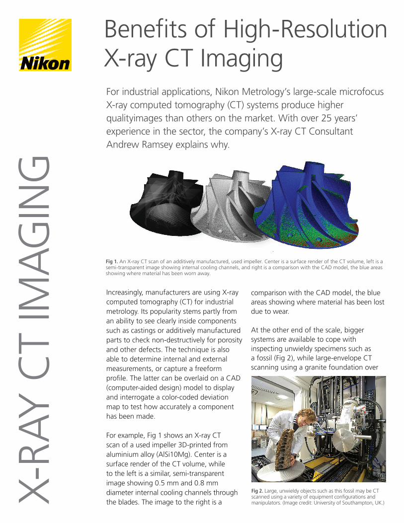
For example, Fig 1 shows an X-ray CT scan of a used impeller 3D-printed from aluminium alloy (AlSi10Mg). Center is a surface render of the CT volume, while to the left is a similar, semi-transparent image showing 0.5 mm and 0.8 mm diameter internal cooling channels through the blades. The image to the right is a
comparison with the CAD model, the blue areas showing where material has been lost due to wear.
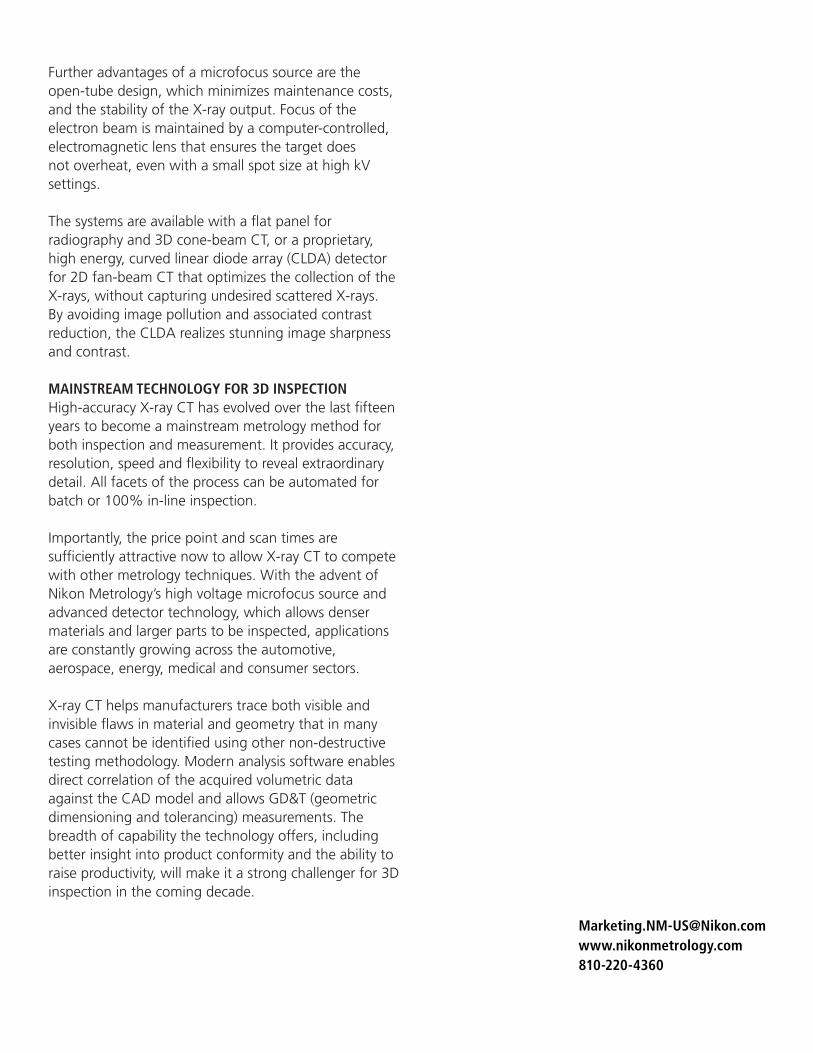
At the other end of the scale, bigger systems are available to cope with inspecting unwieldy specimens such as a fossil (Fig 2), while large-envelope CT scanning using a granite foundation over
For industrial applications, Nikon Metrology’s large-scale microfocus X-ray computed tomography (CT) systems produce higher qualityimages than others on the market. With over 25 years’ experience in the sector, the company’s X-ray CT Consultant Andrew Ramsey explains why.
X-RA
Y C
T IM
AG
ING
Fig 2. Large, unwieldy objects such as this fossil may be CT scanned using a variety of equipment configurations and manipulators. (Image credit: University of Southampton, UK.)
Fig 1. An X-ray CT scan of an additively manufactured, used impeller. Center is a surface render of the CT volume, left is a semi-transparent image showing internal cooling channels, and right is a comparison with the CAD model, the blue areas showing where material has been worn away.

four metres in length can measure objects weighing up to 150 kg, for example an engine block. Such systems can be configured as a walk-in room if desired, with various alternative manipulators, multiple sources and detectors, and panels that can be shifted sideways to simulate wider detectors. In all cases, clarity is the watchword. If images are blurry, the metrology will be compromised.
In this article, Andrew Ramsey examines the importance of ensuring that an X-ray CT system has minimum unsharpness (loss of spatial resolution in the radiographic image) for industrial applications. He argues that Nikon Metrology’s series of high power, 225, 320 and 450kV microfocus X-ray sources, which are designed and
manufactured in-house, are preferable to traditional minifocus technology used by other manufacturers. It is because the smaller microfocus spot size allows geometric magnification of the images onto a larger, more efficient detector, allowing more X-rays to be captured. The more X-rays that are imaged, the greater the signal-to-noise ratio, giving rise to better quality images.
Having a cleaner representation of the hundreds or even thousands of 2D X-rays as they pass through the specimen at all angles facilitates precise calculation of the linear attenuation coefficients at every point within a 3D
volume containing the sample. A computer algorithm is then able to construct more faithfully the object’s internal structure from the intensity values in the projected images to produce an accurate digital reconstruction.
UNSHARPNESS IS THE ENEMYA CT scan with four times the resolution of a typical medical scan requires 256 times the X-ray dose, which would be harmful to a patient, but in industrial CT it is not a problem. The X-rays can also be much more powerful to see inside dense, thick metals.
The other difference with industrial scanning is that the specimen under test is rotated so it can be imaged
from all directions, which is much more convenient than having to rotate the equipment around a person, who would not appreciate being spun through 360 degrees. Otherwise the two applications are comparable and both are subject to unsharpness, which comes in two forms - motion and geometric.
Motion is a problem in medical scanning because the patient is breathing and liable to move relative to the X-ray source during the process. This difficulty can be discounted in industry, as the workpiece is securely clamped. Geometric unsharpness is caused by aspects of the X-ray beam. To minimize it, a fine beam and a short
Fig 3. Graphical representation of the difference between the principles of minifocus and microfocus X-ray CT
Fig 4. An Inconel test part scanned using both minifocus and microfocus X-ray CT. (Image credits: design - National Institute of Standards and Technology; manufacture - Delta Airlines.)
Fig 5. Part of the scan resulting from minifocus X-ray CT. Fig 6. The same area scanned using microfocus X-ray CT, resulting in a much sharper image.

focal spot to object distance are needed.
HIGH SOURCE VOLTAGE COMBINED WITH SMALL FOCAL SPOT SIZE IS OPTIMALAccording to Ramsey, it is the small size of the X-ray focal spot inside the source used in Nikon Metrology’s CT systems that sets them apart from the competition. It enables images to be magnified onto a thicker scintillator in the detector and hence allows larger pixels to be used without losing sharpness.
Nikon Metrology is the only company that produces a source above 300kV with a small focal spot. Its 450kV source was recently measured to be around 55μm in diameter up to 100W, rising to only 85μm at the full power of 450W. In contrast, high-voltage minifocus sources have much larger spot sizes measuring around 400μm and upwards. Based on experimental data, at these high energies the best geometric unsharpness is obtained with a Nikon Metrology XT H 450kV microfocus system.
The manufacturer’s lower voltage sources go down to a 3μm spot size and there is a special, high-resolution 1μm version, allowing incredible detail to be seen.
Attempting to obtain such performance by lowering the size of the target’s pixels would reduce the efficiency of detection by a factor equivalent to the cube of the pixel size reduction. By reducing the source size instead, the number of available X-rays reduces only linearly. Lower voltage high-resolution sources are available, but for denser objects a high voltage is needed to penetrate them.
In summary, minifocus sources rely on thin detectors with a small-pixel scintillator to obtain high resolution images. Smaller pixel detectors need thinner scintillators to avoid blurring the images over several pixels, but these are less efficient at detecting X-rays so more pass straight through without being seen, making the images more noisy.
Using a microfocus source, on the other hand, the image can be magnified onto a larger-pixel detector with a thicker scintillator, which more than makes up for the lower power. In any case, the flux can be increased by up to six-fold using a rotating rather than a static target. Fig 3 shows a graphical representation of the difference between the principles of microfocus and minifocus X-ray CT. For resolutions less than about 0.5mm, it is always more efficient to use a microfocus source.
COMPARATIVE TEST RESULTSAll this is fairly technical, but what does it mean in practice? Fig 4 shows an Inconel test part scanned using both minifocus (Fig 5) and microfocus (Fig 6) X-ray CT. The slots and holes are much clearer and better defined on the microfocus CT image and are easier to measure. Comparative CT scans of an actual component, a motorcycle engine casting, are shown in Figs 7 (minifocus) and 8 (microfocus). Again, the improvement in the latter image is apparent.
If inspecting for porosity and inclusions, Fig 9 of minifocus (left) and microfocus (right) CT imaging respectively tells a similar story. The right hand image is much clearer, providing better identification of larger voids (green) and revealing smaller inclusions (red) that are invisible in the left hand image.
The microfocus source that powers Nikon Metrology X-ray CT scanners allows data to be collected significantly faster for a given power. Alternatively for a given measurement time, the available resolution will be higher, so data quality is improved.
Fig 9. Minifocus (left) and microfocus (right) X-ray CT of the same component. The right hand image is clearer, providing better identification of larger voids (green) and revealing smaller inclusions (red) that are invisible in the left hand image.
Fig 7. A motorcycle engine casting scanned using a minifocus X-ray CT system.
Fig 8. The same motorcycle engine casting scanned using a Nikon Metrology microfocus X-ray CT system, showing considerably sharper detail.
Further advantages of a microfocus source are the open-tube design, which minimizes maintenance costs, and the stability of the X-ray output. Focus of the electron beam is maintained by a computer-controlled, electromagnetic lens that ensures the target does not overheat, even with a small spot size at high kV settings.
The systems are available with a flat panel for radiography and 3D cone-beam CT, or a proprietary, high energy, curved linear diode array (CLDA) detector for 2D fan-beam CT that optimizes the collection of the X-rays, without capturing undesired scattered X-rays. By avoiding image pollution and associated contrast reduction, the CLDA realizes stunning image sharpness and contrast.
MAINSTREAM TECHNOLOGY FOR 3D INSPECTIONHigh-accuracy X-ray CT has evolved over the last fifteen years to become a mainstream metrology method for both inspection and measurement. It provides accuracy, resolution, speed and flexibility to reveal extraordinary detail. All facets of the process can be automated for batch or 100% in-line inspection. Importantly, the price point and scan times are sufficiently attractive now to allow X-ray CT to compete with other metrology techniques. With the advent of Nikon Metrology’s high voltage microfocus source and advanced detector technology, which allows denser materials and larger parts to be inspected, applications are constantly growing across the automotive, aerospace, energy, medical and consumer sectors.
X-ray CT helps manufacturers trace both visible and invisible flaws in material and geometry that in many cases cannot be identified using other non-destructive testing methodology. Modern analysis software enables direct correlation of the acquired volumetric data against the CAD model and allows GD&T (geometric dimensioning and tolerancing) measurements. The breadth of capability the technology offers, including better insight into product conformity and the ability to raise productivity, will make it a strong challenger for 3D inspection in the coming decade.