bentonite hdpe composite waterproofing systems; … hdpe composite... · • soil nailing • other...
TRANSCRIPT

7/8/2010
1
Architectural Engineering firm established in 1987
Karim P. Allana, PE, RRC, RWC
104 employees in in California, Nevada and Hawaii, Washington with Expertise in:
Construction Forensics; Exterior walls systems; Remedial design and engineering; Roofing; Waterproofing; Structural engineering; Mechanical engineering; Construction
Introduction
Case History, Downtown Sunnyvale Garage, Below Grade Waterproofing F ilFailure
• 2nd Largest Below Grade Structure in Northern California
• 4 stories underground• 12 to 14 feet in the water table• Started Leaking as soon as dewatering pumps were
turned off
7/8/2010
2
Introduction cont.
Focus of the presentation:• Case Study of a failed blindside y
waterproofing system• Soil retention systems and their impact
on waterproofing Failure• Sodium bentonite based waterproofing
systems used in blind-side constructionsystems used in blind side construction• DeNeef Hydroactive Grout Injection
Repair. One of the largest injection repair projects in the country
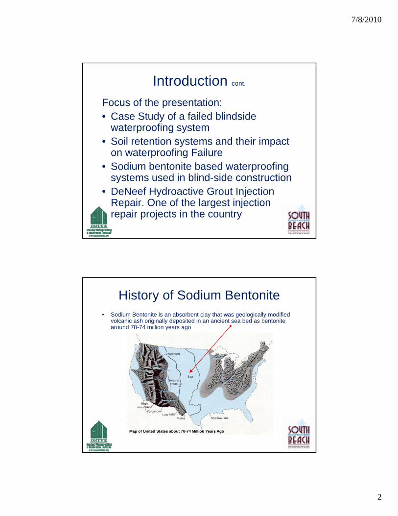
History of Sodium Bentonite• Sodium Bentonite is an absorbent clay that was geologically modified
volcanic ash originally deposited in an ancient sea bed as bentonite around 70-74 million years ago
Map of United States about 70-74 Million Years Ago

7/8/2010
3
History of Sodium Bentonite Cont.
Properties of Bentonite• An absorbent aluminum
phyllosilicate generally composed of impure claycomposed of impure clay
• Two types of Bentonite –swelling (sodium bentonite) and non-swelling (calcium bentonite)
• Sodium bentonite absorbs up to 8x’s it’s dry mass in water
• Contains exchangeable di tisodium cations
• Calcium Bentonite can be converted to Sodium Bentonite through “ion exchange”
Sodium Bentonite Granules Transform into a seamless, monolithic membrane to provide an excellent barrier to water
Bentonite Seals When Wetted Cont.
water
Time Sequence Photography
1. Bentonite Installed Dry
2. Granules quickly transform when wet
3. Seamless Bentonite
Membrane

7/8/2010
4
Upon hydration, bentonite extrudes out and seals the overlap seams
Upon hydration, bentonite extrudes out and seals the overlap seams
Bentonite Requires Confinement
When hydrated, bentonite expands pand conforms to irregular surfaces, penetrations, and infiltrates cracks and voids in theand voids in the concrete

7/8/2010
5
Soil Retention Systems
• Common soil retention systems include:
• Wood Lagging & Soldier Piles
• Shotcrete Lagging
• Soil Nailing
• Other systems
Original Bentonite Waterproofing System
7/8/2010
6
Positive & Negative Side Waterproofing
Defined – Positive-side waterproofing is Defined – Positive-side waterproofing is applied to the outside (wet) face of the subsurface building components in contrast to Negative-side waterproofing, which is applied to the inside (dry) face f th b f ll d l bof the subsurface walls and slabs.
Blind-side Waterproofing
• Defined – Blind-side is positive-side
• Blind-side waterproofing systems are p g yrequired where the exterior faces of foundation walls are not accessible, which requires application of the waterproofing system to the formwork surface facing the excavation.
• This results in the waterproofing’s final location to be on the outside of the foundation wall.

7/8/2010
7
Property Line Applications
Earth Retention Systems
• Review different types of Lagging systems used for blind sidesystems used for blind side waterproofing
• Review issues associated with lagging that impact sodium bentonite waterproofing systems

7/8/2010
8
Wood Lagging - Earth Retention System
Conventional Wood Lagging

7/8/2010
9
Shotcrete Lagging
• Soldier piles are predrilled at intervals along the wall's baseline The piles arealong the wall s baseline. The piles are placed in the hole and backfilled with lean-mix concrete. As the excavation in front of the wall proceeds, shotcrete lagging is installed between the soldier il i lift Ti b k h bpiles in lifts. Tieback anchors may be
installed and stressed to provide lateral restraint.
Shotcrete Lagging

7/8/2010
10
Shotcrete Lagging
Shotcrete Lagging

7/8/2010
11
Included in This Presentation
• Review 2 of the most widely used bentonite systems on the markety
• Different makeup of the systems and specific uses
• Benefits and Limitations
• Author not endorsing any product or system
Sodium Bentonite Limitations.
Inherent limitations of Bentonite HDPE• Requires compaction/confinement to be q p
effective – a minimum of 24 psf is required
• Application in brackish or slightly salt groundwater
• Standing water during construction –Standing water during construction premature hydration
7/8/2010
12
Commercial Bentonite/HDPE Products
Product Reviewed :
• Tremco - Paraseal LG– Multi-layer sheet membrane waterproofing system
• CETCO – Volclay Voltex DS– Interlocking Geotextile waterproofing panel system
Tremco – Paraseal LG
• Multi-layer (3-layer) sheet membrane waterproofing systemg y
1. Consists of self-sealing, expandable layer of granular bentonite
2. Bentonite layer is laminated to HDPE sheet3. Covered with a protective layer of spun
polypropylene
• Controlled thicknesses of 170 mils to 200 mils
• Designed for blind-side installations

7/8/2010
13
Tremco – Paraseal LG Cont.
Blindside application
• Applied before walls are poured• Applied before walls are poured
• Designed to resist damage from:– Some exposure to inclement weather
– Normal concrete pours
– Direct installation of shotcrete
• Can be used in hydrostatic head conditions
Prehydration Due to Rain can Lead to Failure
Hydration during Hydration during construction can construction can
be a problembe a problem
7/8/2010
14
Tremco – Paraseal LG Cont.
Additional Specifications• HDPE Laps can be sealed with butylHDPE Laps can be sealed with butyl
tape for gas membrane and additional level of waterproofing
• Penetrations need to be detailed properly
• Puncture resistant HDPE liner of 169 lb• Puncture resistant HDPE liner of 169 lb point load
• Protect from moisture during storage. Do not double stack
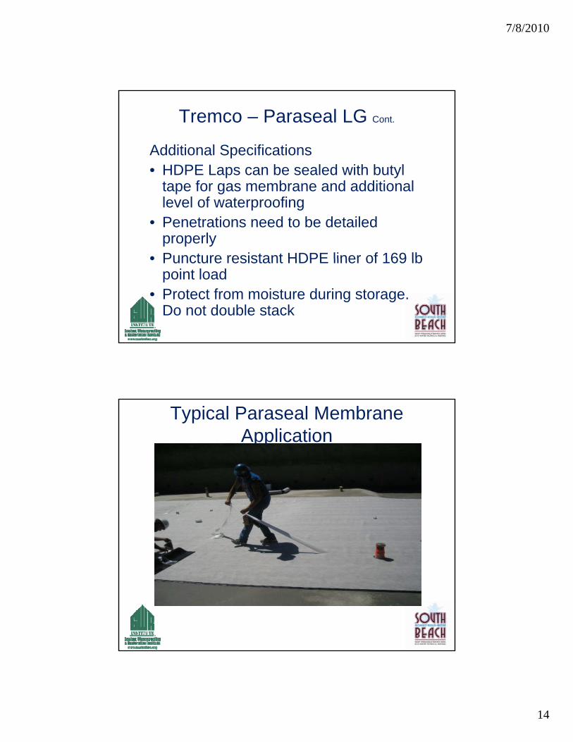
Typical Paraseal Membrane Application

7/8/2010
15
Seam Tape Being Applied
7/8/2010
16
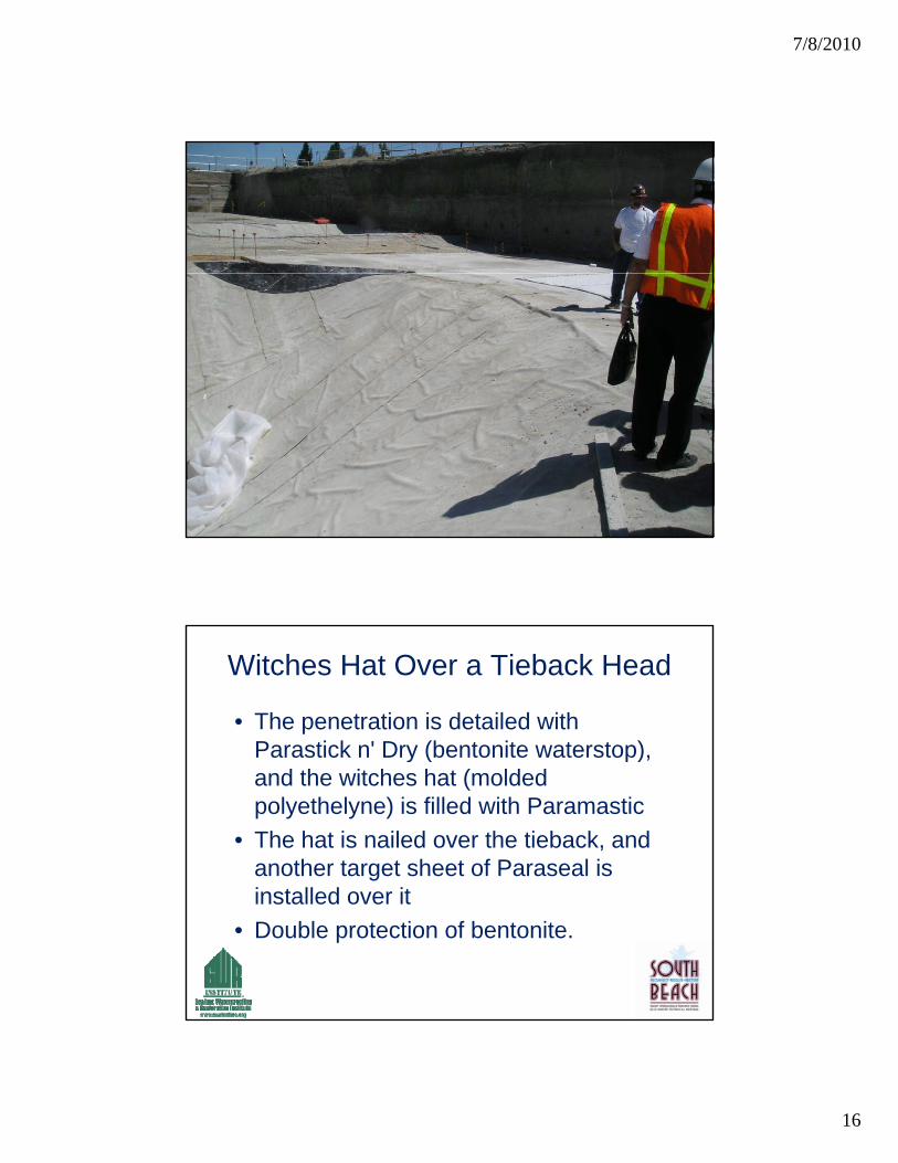
Witches Hat Over a Tieback Head
• The penetration is detailed with Parastick n' Dry (bentonite waterstop),Parastick n Dry (bentonite waterstop), and the witches hat (molded polyethelyne) is filled with Paramastic
• The hat is nailed over the tieback, and another target sheet of Paraseal is i t ll d itinstalled over it
• Double protection of bentonite.

7/8/2010
17
….…and nailed
CETCO – Volclay Voltex DS
• Interlocking Geotextile Waterproofing System
1 Comprised of two high strength geotextiles1. Comprised of two high-strength geotextiles sandwiching bentonite, which are interlocked through a needle punching process
2. Includes a integrated polyethylene liner for added protection and vapor barrier
• Sandwiches 1.10lbs of bentonite per square footfoot
• Designed for waterproofing under slabs and blind-side applications

7/8/2010
18
CETCO – Volclay Voltex DS Cont.
• Unique Design Feature
• Concrete/shotcrete clings to geotextileConcrete/shotcrete clings to geotextile fibers
• Allows waterproofing panels to stay in place, against concrete and shotcrete walls
• Designed only for below-grade waterproofing applications
VOLTEX DSCROSS-SECTION ILLUSTRATION
HDPE LINERNON-WOVEN FABRIC
GRANULAR BENTONITE1.1-LBS./SFWOVEN FABRIC

7/8/2010
19
VOLTEX DS ®
BENTONITE GEOTEXTILE WATERPROOFING WITH INTEGRATED HDPE LINER
VOLCLAY VOLTEXVOLCLAY VOLTEX SOLDIER PILE & LAGGING APPLICATION

7/8/2010
20
Paraseal / Voltex ComparisonTECHNICAL DATA
Physical Properties Method Paraseal LG Value Voltex Volclay Value
Tensile Strength: Membrane (PSI) 4,000 PSI (27.6MPa) N/A
Resistance to microorganisms (bacteria, fungi, mold, yeast) unaffected unaffected
Elongation-ultimate failure of membrane 700% N/A
Puncture Resistance 169 lbs (76.6kg) 140 lbs (63.5kg)
Hydrostatic Pressure Resistance 150 Ft (45.6m) 231 ft. (70 m)
Resistance to water migration under membrane: zero leakage 150 Ft (45.6m)/Head 150 Ft (45.6m)/Head
Grab Tensile Strength N/A 95 lbs. (422 N)
Permeance 2.7x10⁻¹³cm/sec 1 x 10⁻¹⁰ cm/sec.
Installation Temperatures -25°F to 130°F (-31.7°C to 54.4°C)
Low Temperature FlexibilityNo effect before or after
installation Unaffected at -25°F (-32°C)
Source, Manufacturer’s published data
Project Case Study• Forensic Case Study Sunnyvale, California• Waterproofing failure of Downtown Sunnyvale
GarageGarage• Work performed for a construction defect
litigation case• Bentonite/HDPE composite system was
installed and had failed• 2nd largest below-grade structure in Northern
CaliforniaCalifornia• Largest below-grade waterproofing repair of
it’s kind in California

7/8/2010
21
Project Case Study Cont.
• Structure experience extensive leaking throughout below-grade perimeter wallsg g p
• Built on zero lot line with shotcrete foundation walls against wood lagging and soldier pile retention walls
Project Case Study Cont.
• Core samples taken from 18” thick shotcrete walls
• Partial excavation behind lagging
• Reviewed original construction drawings
• Reviewed lagging installation photos
• Reviewed soil consolidation
• Visual observations of leaks and water testing

7/8/2010
22
Garage Structure is 2 stories Below the Water Table
Downtown Sunnyvale Garage Leaked From Day 1
7/8/2010
23
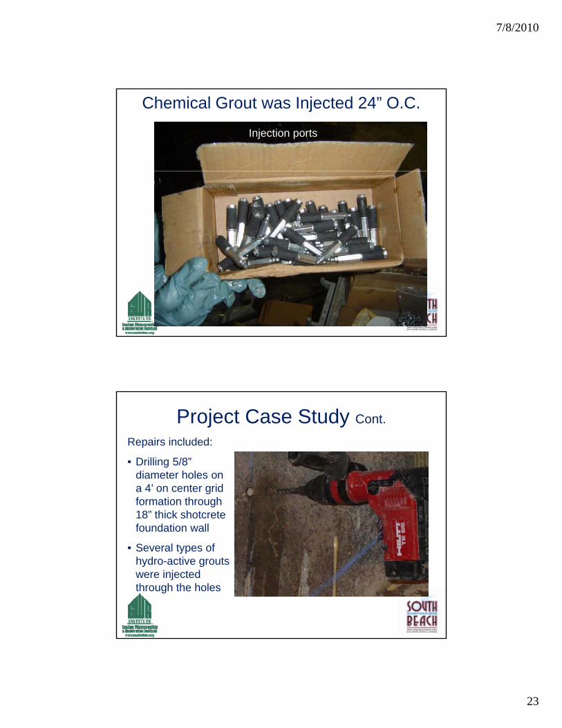
Chemical Grout was Injected 24” O.C.
Injection ports
Project Case Study Cont.
Repairs included:
• Drilling 5/8” diameter holes ondiameter holes on a 4’ on center grid formation through 18” thick shotcrete foundation wall
• Several types of hydro-active grouts were injected through the holes

7/8/2010
24
Repair work in progress
Typical Injection Equipment

7/8/2010
25
Grout Creates a “Curtain” Behind Concrete
Foam Sometimes Leaves a Mess

7/8/2010
26
Concrete Cores Were Taken To Asses Performance
Cores Showed Large Voids Behind Shotcrete
Foam Grout 5” VoidFoam Grout 5 Void behind Concrete
7/8/2010
27
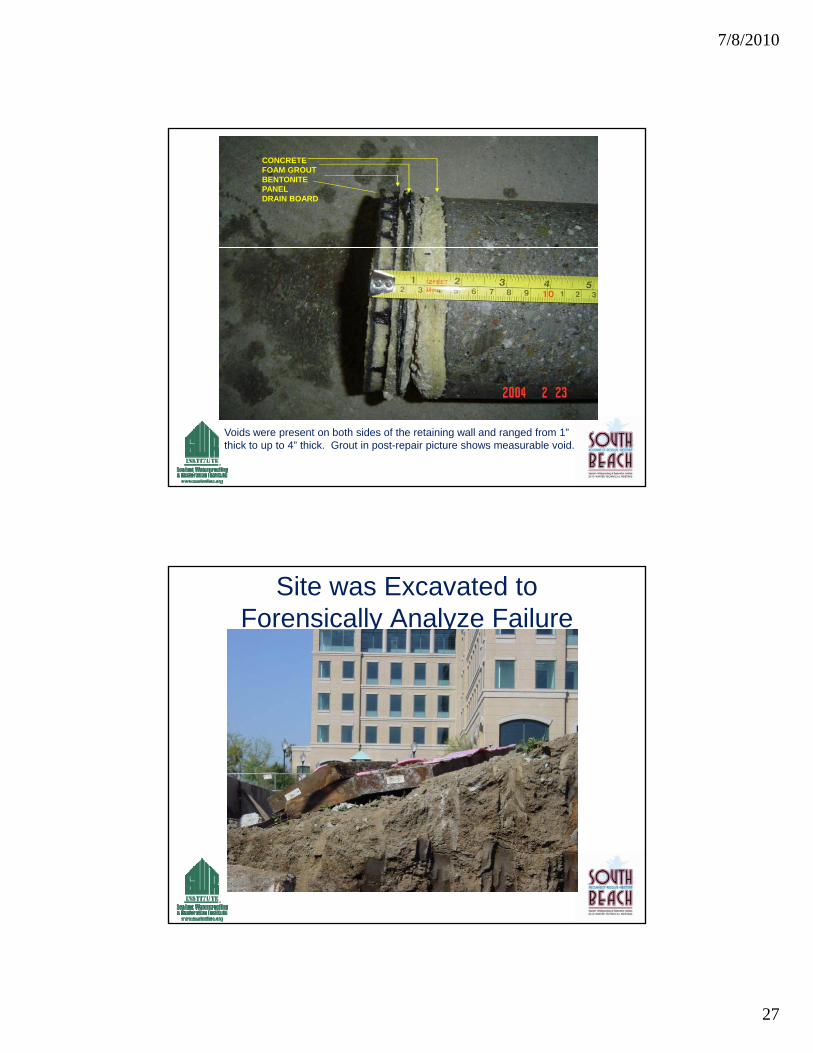
CONCRETEFOAM GROUTBENTONITE PANELDRAIN BOARD
Voids were present on both sides of the retaining wall and ranged from 1” thick to up to 4” thick. Grout in post-repair picture shows measurable void.
Site was Excavated to Forensically Analyze Failure

7/8/2010
28
Site was Excavated to Forensically Analyze Failure
Gap Between Lagging and Shotcrete
7/8/2010
29
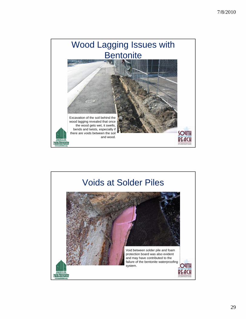
Wood Lagging Issues with Bentonite
Excavation of the soil behind the wood lagging revealed that once
the wood gets wet, it swells, bends and twists, especially if
there are voids between the soil and wood.
Voids at Solder Piles
Void between solder pile and foam protection board was also evident and may have contributed to the failure of the bentonite waterproofing system.

7/8/2010
30
Void behind foam protection board
Void Behind Protection Board
7/8/2010
31
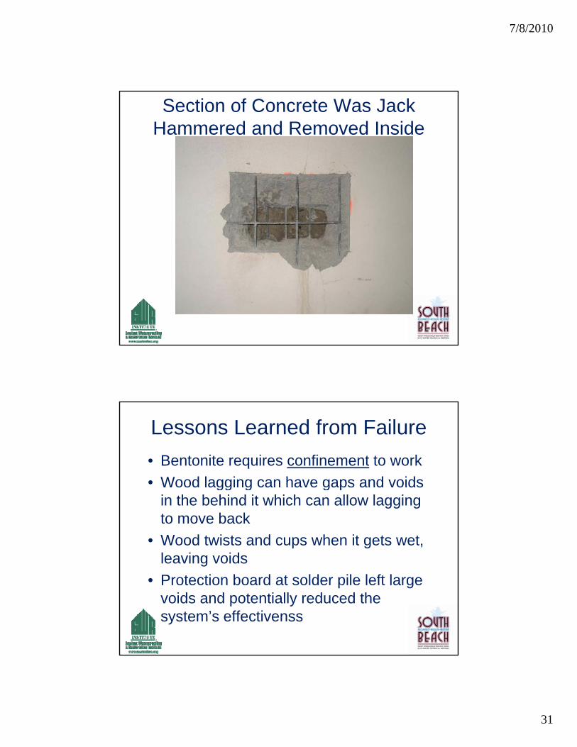
Section of Concrete Was Jack Hammered and Removed Inside
Lessons Learned from Failure
• Bentonite requires confinement to work
• Wood lagging can have gaps and voidsWood lagging can have gaps and voids in the behind it which can allow lagging to move back
• Wood twists and cups when it gets wet, leaving voids
• Protection board at solder pile left large voids and potentially reduced the system’s effectivenss

7/8/2010
32
Project Case Study Cont.
• Grout Characteristics
• Quickly expands and cures upon contact with water to form a water barrier behind the surface of the wall and under portions of the slab
• Designed to fill an voids behind foundation wall
• Upon reaching maximum confinement, grout continues to internally expand thus increasing in density
Project Case Study Cont.
• Case Study Conclusion
• Potential factors in failure– Cast-in-place concrete
– Lagging
– Soil consolidation
• Voids can be large and require a lot more grout. Don’t under-estimate grout requirement
• Lessons learned – led to change in manufacturers specifications
7/8/2010
33
Karim P. Allana, PE, RRC, RWC
Senior Principal
California – Hawaii – Nevada - Washington
Thank You
Questions?