beverly jones heydinger nancy lange dan lipschultz john tuma
TRANSCRIPT
STATE OF MINNESOTA
BEFORE THE MINNESOTA PUBLIC UTILITIES COMMISSION
Beverly Jones Heydinger Nancy Lange Dan Lipschultz John Tuma Betsy Wergin
Chair Commissioner Commissioner Commissioner Commissioner
IN THE MATTER OF THE 2015 MINNESOTA BIENNIAL TRANSMISSION & DISTRIBUTION PROJECTS REPORT
Docket No. E999/M-15-439
GRID MODERNIZATION REPORT
INTRODUCTION
Northern States Power Company, doing business as Xcel Energy, submits this Grid Modernization Report in the above-referenced docket in compliance with Minn. Stat. § 216B.2425, subd. 2(e) and 8. This provision, which was approved in the 2015 Legislative Special Session, requires a utility operating under an approved multiyear rate plan to identify in its Biennial Transmission and Distribution Plan:
investments that it considers necessary to modernize the transmission and distribution system by enhancing reliability, improving security against cyber and physical threats, and by increasing energy conservation opportunities by facilitating communication between the utility and its customers through the use of two-way meters, control technologies, energy storage and microgrids, technologies to enable demand response, and other innovative technologies.
This new statutory language reflects the growing interest in ensuring the distribution system is well-positioned to meet future system and customer needs while maintaining reliability, safety and security. The Commission is advancing this discussion through its Investigation into Grid Modernization in Docket No. E999/CI-15-556. The Company is actively participating in this effort and looks forward to continued dialogue on bringing new capabilities, functions and technologies to the distribution grid. Because these discussions are just beginning in Minnesota, we view this report as preliminary and a precursor to future planning efforts. Our goals for this report are to: (1) highlight the foundational investments we are making and planning to make in the grid, (2) identify future grid applications, and (3) describe in greater detail two projects for which we are seeking certification prior to requesting cost recovery, as allowed under
1
Minn. Stat. § 216B.16, Subd. 7b(b)(5). These two projects are: (1) Advanced Distribution Management System (ADMS) and (2) a solar plus battery storage demonstration project. We understand the statute requires a certification process and look forward to working with stakeholders to defining and understanding this process. In addition, we also discuss a variety of other projects that are currently under evaluation that we may seek certification of in future reports. These include a Fault Location, Isolation, and Service Restoration (FLISR) system, Advanced Metering Infrastructure (AMI), and Integrated Voltage and VAr Optimization (IVVO), as discussed further below. As we have done in years past, we filed a joint Biennial Transmission Projects Report in this docket with the other utilities that own or operate electric transmission lines in Minnesota. However, since we are the only utility currently required to file the distribution portion of the report, we are submitting this report separately from the joint transmission report. Finally, Minn. R. 7848.1900 provides that utilities must submit to the Commission by June 1 of the year the biennial report is due a proposed notice plan to landowners and areas surrounding proposed transmission lines for which certification will be sought as part of the biennial reporting process. Since the June 1 deadline to file this notification plan was before the legislation authorizing us to file this distribution report was finalized on June 13, 2015 and it is unclear whether this Minnesota Rule applies to certification for distribution projects, we did not file a proposed notice plan. However, to the extent the Commission believes Minnesota Rule 7848.1900 applies to distribution project certification requests, we respectfully request the Commission grant a variance.
This report is organized as follows: • Expected Benefits of the Modern Grid; • Foundational Elements of Grid Modernization; • Planned Future Applications; • Grid Modernization Projects for Certification; • Distribution Study; and • Potential Variance Request.
We support the evolution of the grid and anticipate meeting our customers’ expanding energy needs at the “speed of value.” We look forward to continued discussions and learning opportunities surrounding grid modernization with stakeholders.
2
REPORT
Enabled in large part by technological advancement, the country’s distribution grids are beginning to evolve from a predominantly one-way system to an integrated network of centralized and decentralized energy resources that are connected and optimized through communication systems that share information across the grid. This future grid is expected to leverage automation and real-time monitoring to improve system efficiency and performance, prevent disruptions, and reduce the duration and impact of outages. Expanded sensors and controls will manage power flows and support new generation, load, and storage technologies. Security protocols will protect against, detect and remedy cyber and physical threats. These new system capabilities will expand the options available to customers, who will increasingly expect a more customized, convenient and clean energy experience that preserves the high reliability they have come to depend upon. Here in Minnesota, the Company has also begun this transition. We are taking a “building block” approach, focusing first on the foundational elements needed to support fundamental applications. With those fundamental applications in place, more advanced applications are enabled. For example, in order to enable the full system functionality and benefits of ADMS, a secure, two-way communications network is required. This two-way communications system, a Field Area Network (FAN), is an end-to-end communications network that will provide connectivity to the Company’s field devices, allowing the devices to be remotely operated and maintained. The FAN will also enable communication and interoperability across the system, including meters, distributed generation systems, energy storage, microgrids, and other technologies. Then, with both the foundational ADMS and FAN in place, a FLISR system can be deployed to secure substantial reliability improvements. The timeline for actual implementation of these building blocks is fluid to allow for the pace of technological maturity, evolving system needs and customer interests, and Commission and stakeholder input regarding the desired scope and pace of implementation. Many of the grid modernization technologies and devices discussed within this report are relatively new within the industry. We are working with the industry and vendor partners to identify and implement solutions which leverage open architecture and interoperability. Solutions are maturing and we are implementing them, however, we need to balance the need for new solutions with the needs of our current grid without negatively impacting our customers. We believe it is important to take a measured, incremental approach to ensure that we balance cost and customer value with other policy objectives.
3
A. Expected Benefits of the Modern Grid A modern grid will function as an enabler—it will allow for higher integration of renewable resources, greater system efficiency and optimization, and a broader range of energy services. Below are a sample of the key benefits we expect to see from the modern electric grid and are forefront in our minds as we evaluate, strategize, and plan for our upcoming investments and next steps. Reliability & Resiliency. The modern grid will be more reliable and disturbances will be shorter and impact fewer customers. We will have heightened awareness about the current behaviors and health of the grid due to the intelligent devices in the field that are able to sense and adjust power flow, as well as provide intelligence on the current status at local points on the grid. Automation of certain parts of the system will allow the grid to dynamically respond to adverse conditions and restore portions of the system without human intervention. Additionally, when we do have outages, the grid will provide a more accurate understanding of exactly who is out of power and possible fault locations enabling quicker and more efficient outage response. Safety. The new grid will be safer as a result of greater awareness of the grid condition due to more measurement points, real time data, and predictive capabilities that will allow us to understand the behavior of the grid when we switch or modify the distribution system. Improved information will allow us to be more proactive in our maintenance and service work, making a safer environment for our workers and customers. The automation of the system will allow for remote switching, which is then accomplished without the employee in close proximity to the switching action. Outage isolation and fault location prediction will limit drive time to find the source of the outage. We do note that the introduction of distributed generation presents safety concerns, but believe these concerns will be met through adherence to good standards, processes, and safety codes. Efficiency. Enhanced monitoring will enable us to know, rather than estimate, how elements of the system are loaded. This knowledge will help us make more informed decisions about when and where to improve or modify the grid ensuring we use financial and labor resources most efficiently. The modern grid will also operate more efficiently by minimizing energy losses through optimal power factor correction and potentially through optimized switching. Customer Choice. The modern grid will serve as a platform that facilitates customer adoption of new products, services and technologies, including greater data sharing. With this platform, utilities will become more consumer-centric than ever before. Utilities can 4
create “storefronts” that offer a suite of energy solutions and connect customers with the resources and tools they need to meet their energy goals. This may include energy information and advice, innovative utility-provided products, and services through valued third party partners. These new offerings will enhance the ability of customers to manage their bills and to personalize their energy experience. B. Foundational Elements of Grid Modernization In order to fully realize the benefits of the modern grid, we must prepare our current grid. Our upcoming rate case (Docket No. E002/GR-15-826) discusses the investments we are making today and in the near term that will support the longer term grid modernization efforts. For example, we are leveraging equipment replacement opportunities to consider whether the functionality of a particular asset can be enhanced to promote grid modernization. One example of this is our plan to replace electro-mechanical relays with solid-state relays that are not only communication-enabled, but are also capable of providing fault data that an ADMS system can use to calculate probable fault location. This enables us to more quickly identify faults on our system and improve our response time. Additionally, voltage regulators purchased for replacements will have controls that identify reverse-power flow and react accordingly, which will facilitate integration of distributed generation onto the system.
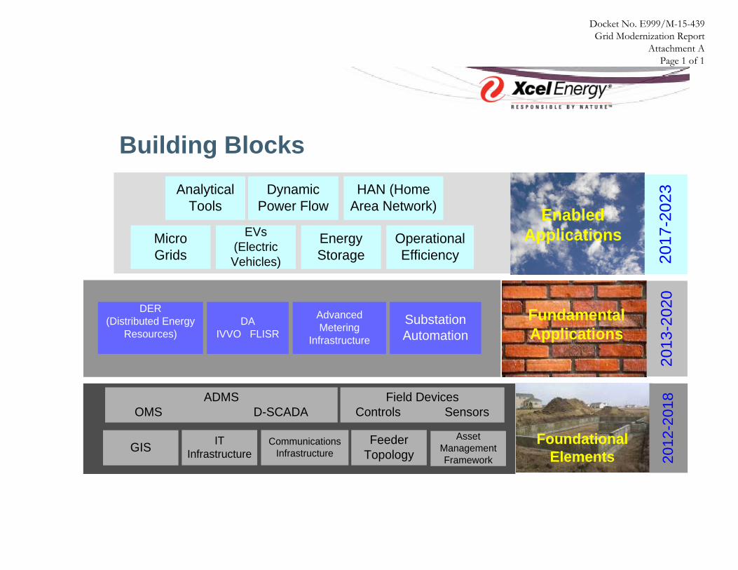
While these asset replacement plans are being thoughtfully considered and planned with grid modernization in mind, we also have a necessary layer of new foundational elements to implement as we fulfill our vision of building an integrated grid. We have provided a “Building Block” slide in previous stakeholder discussions which lays out our framework for building this integrated grid. We have provided this building block slide as Attachment A and describe these foundational elements below. As noted on Attachment A, prior stakeholder presentations, and previous Smart Grid reports,1 our rollout of these foundational elements is planned to occur between the years of 2012-2018.
• Advanced Distribution Management System (ADMS) – An ADMS provides an integrated operating and decision support system to assist control room, field personnel, and engineers with the monitoring, control and optimization of the distribution system. We note that the Outage Management System (OMS) functionality is planned to be enabled in the ADMS system at some point in the future, allowing EMS, DMS, and OMS functions to be managed through one
1 Docket No. E999/CI-08-948 5
system. ADMS is one of the projects we are requesting certification of and is discussed further below.
• Energy Management System (EMS) – We use an EMS to monitor and manage the automated devices on our distribution and transmission systems. As discussed in our upcoming rate case by Mr. David Harkness, our new Dynamic EMS (DEMS) was designed with security in mind and will address all NERC Critical Infrastructure Protection V5 requirements. DEMS will also contain many enhanced functional improvements in the basic Supervisory Control and Data Acquisition (SCADA) function, will improve support for advanced application functions that standardize operator capabilities, and will add functionality regarding circuit management.
• Distribution Supervisory Control and Data Acquisition (SCADA) – Our SCADA system
provides information to control center operators regarding the state of the system and alerts when system disturbances occur, including outages. Our use of SCADA technology improves outage restoration, system performance, and planning engineering. Every few seconds it provides system status information, such as operating parameters for our generation and substation facilities. It also immediately notifies an operator of disturbance types (sustained or momentary event), so that system impacts can be assessed and operations can take appropriate action to restore service to our customers. Our SCADA system also monitors and collects system performance information for feeders and substations. This information is used by transmission and distribution operations to ensure the system is safely and efficiently operating within its capabilities. The performance information is also used by planning engineers to perform load and operating analyses to establish system improvement programs that ensure we adequately meet load additions and continue to provide our customers with strong reliability. As discussed by Ms. Kelly A. Bloch in our upcoming rate case, we currently have SCADA in 120 of our Minnesota distribution substations (which serve 92% of our MN customers), leaving 98 substations without remote visibility or control. Given the importance of this technology, we have outlined a long-term capital investment plan starting in 2016 to install SCADA at three to four distribution substations each year.
• Field devices – A large deployment of distribution power line sensors is planned in Minnesota in 2015 and early 2016. These sensors will provide power quality data, fault information and other critical information for operating the distribution grid. These sensors are planned for substations that are without SCADA as referenced above. The installation of SCADA at all distribution substations is costly and at current funding rates, will take many years to complete. This new technology
6
provides much of the benefit from SCADA and is an interim solution until SCADA has been installed. 30 substations are planned to have this technology installed and available in the DEMS system. In addition to the power line sensors, several other modern field device technologies are used on the distribution system in Minnesota, including the following:
o Capacitor controls – these have two-way cellular modems which are used to manage power factor and reduce system losses through the SmartVAR system.
o Automated Switch controls – these are used with a FLISR system and automatically isolate faulted feeder sections and restore power to customers.
o Remote Fault Indicators – these are an inexpensive way to alert operations of a fault on the system and also minimize patrol time.
o Step-Down monitors, which monitor the temperature and loading of large transformers primarily used to step voltages from 34.5 kV to 13.8 or 12.5 kV.
• Geographic Information System (GIS) – This system contains location-specific
information about assets. GIS allows us to view, understand, question, interpret, and visualize data in many ways that reveal relationships, patterns, and trends in the form of maps. As discussed by Mr. Harkness in our upcoming rate case, we are planning an upgrade for this system in 2016. This upgrade will help maintain system reliability and provide additional capabilities and enhanced system performance. GIS is a foundational tool and data repository for the grid modernization effort, but it is not a complete solution for the system data needs of the future. Enhanced data structures and future system upgrades will be required.
• IT infrastructure – Our corporate IT infrastructure requires attention and investment on an ongoing basis. An up-to-date infrastructure is necessary for us to continue to meet increasingly demanding cyber security, data traffic, reliability, and compliance requirements, as well as the service expectations of our customers. Many of the investments and projects discussed within this report involve additional data and communication needs and a current IT infrastructure will be critical to supporting those efforts.
• Communications Network – A comprehensive communications network will improve
efficiency through increased standardization, monitoring and remote control of the system in a secure manner. For example, as mentioned above, we are deploying a Field Area Network (FAN), which will provide for two-way communication with devices in the field. As discussed by Mr. Harkness in our upcoming rate case, the FAN will be constructed with substations serving as communications hubs that
7
can aggregate data from the field devices before it is passed to various backend systems. This approach will allow for the data to be available at very low latencies in these substations if in the future we need to add increased intelligence to these locations. Currently, our internal communications networks serving field devices and all external network providers bypass the substations which add delays that can make the data unusable for real time automated operations. Further, by bringing more of the communications network in-house, the Company is able to improve security against cyber threats by reducing third party networks, reducing the use of public networks (i.e., cellular) and reducing the reliance on external entities for communications support. Interoperability from two communications network standards, Wi-MAX2 and Wi-SUN3 in the FAN will make it easier for new technologies, systems and solutions to utilize the network. This will greatly reduce the complexity of establishing SCADA communications to these end-points as well as greatly reduce the cost to implement. The FAN will also enable the use of Quality of Service (QoS) to separate communication channels that might be more important in an emergency situation. QoS is not widely available today with many public communications options.
• Feeder Topology – This element addresses the importance of our planning and design guidelines. This would include decisions around feeder segmentation, the number of closed and open switches, reserve capacity, and protection design.
• System Management Framework – Grid modernization requires expanded standards, strategies, and guidelines for planning, engineering, and design activities. This includes, but is not limited to, new asset strategies for new technologies; asset data attributes, lifecycle evaluations, maintenance strategies, resource planning and new benefits frameworks.
C. Planned Future Applications Once we have the foundational elements in place, we will leverage the capabilities of these foundational elements to enable new grid functionalities and features as discussed below. We expect to expand on this discussion in future reports.
• Distribution Automation (DA) – Our distribution automation efforts will be comprised of two main components:
2 Wi-MAX is Wireless Interoperability for Microwave Access, it is a broadband technology that is high bandwidth and requires line of site for communications. This is intended to be the wireless backbone of the FAN with connections to aggregator nodes as well as critical distribution automation devices. 3 Wi-SUN is Wireless Interoperability for Smart Utility Networks. It is a standard for mesh-networking devices that are lower bandwidth, but do not require line of site, ideal for meters and other sensing devices on the distribution system. 8
1. Integrated Volt Var Optimization (IVVO) – A major piece of IVVO is largely in place in Minnesota due to our SmartVAR Management pilot program , where we replaced existing capacitor bank controls with modern, two-way controls.4 A head-end system was installed to manage capacitor banks across the distribution system to improve power factor on feeders and reduce system losses. The controls communicate with the central control system via commercial cellular transmission. We plan to replace the cellular with FAN radios to reduce operating costs. The system, as well as the capacitor controls also ensures that distribution feeder voltage remain within ANSI C84.1 standards for improved power quality. IVVO takes this control methodology a step further, as it will be capable of integration with voltage regulation equipment, which can then be enabled to reduce system voltage. Reducing voltage is a tool which can be used to reduce load during system peak demand and emergency load situations. In order to safely reduce voltages and stay within ANSI limits, multiple voltage sensing points will need to be installed on each feeder in which IVVO is run on. These sensing points can be from AMI or other discrete voltage sensing options. IVVO is an application of the ADMS system, which leverages many data points from sensing devices across each feeder to run a sophisticated power flow model of the distribution system. This model helps the IVVO application determine which capacitors to turn on and how much to lower the voltage for optimal grid performance. As noted above, we will likely seek certification for cost recovery in a future report for the additional capabilities needed for this system.
2. Fault Location Isolation and Service Restoration (FLISR) – The FLISR system will play an integral role in reducing outage durations and improving overall system reliability. The system consists of intelligent field switches that work to detect feeder mainline faults, isolate the fault by opening section switches, and restore power to unfaulted sections by closing tie switches to adjacent feeders as necessary. This process can be controlled remotely by the Distribution Control Center, and will ultimately be controlled by optimal switching plans generated by ADMS and will be executed automatically. This will reduce the outage duration for the majority of customers on faulted feeders, as this process is completed within seconds or minutes. As discussed by Ms. Kelly Bloch in our upcoming rate case, we have already deployed FLISR on our 34.5 kV system and this has proven to be very effective at improving reliability by saving nearly 15 million customer outage minutes in
4 We filed updates on our SmartVAR Management pilot program with the Commission in Docket No. E002/M-09-1488. 9
Minnesota between 2013 and 2014. Though we do not have any immediate plans, in the future we intend to deploy this program on our interconnected 12.5 kV and 13.8 kV systems and anticipate this may be one of the projects for which we seek certification and cost recovery of in the future.
• Substation Automation –Substation Automation involves upgrading protection relays and schemes, expanding SCADA capabilities, and installing high speed communications inside and outside the substation. Most of our substations with SCADA are well automated; so much of the automation we propose to add will be done in conjunction with SCADA additions that meet specific substation business needs.
• Advanced Metering Infrastructure (AMI) – AMI can be defined as advanced metering systems comprised of state-of-the-art electronic/digital hardware and software, which combine data measurements with continuously available remote communications. These systems enable measurement of detailed, time-based information and frequent collection and transmittal of such information to various parties. AMI typically refers to advanced field devices such as meters, communication networks between field devices and service providers or utilities and data collection and management systems. AMI networks have traditionally been dedicated to solely providing communication to field metering devices with limited support for other applications. Xcel Energy’s FAN strategy seeks to provide a communication network that serves multiple users that include but is not limited to AMI, ADMS, streetlight monitoring and control, and potential for smart inverter monitoring and control (though development in this area is not yet mature). AMI, leveraging the FAN, creates a network between advanced meters, utility business systems, distribution automation field devices and control centers, and allows collection and distribution of information to customers, utilities, and other parties. AMI systems can perform remote service disconnects and reconnects, transmit demand response and load management messages, and the data collected can help the ADMS system control distribution-automation equipment. The advanced meters used in an AMI system can also act as a communications hub to support other applications such as Two Way Demand Response and Home Area Networks should the need arise in the future. In contrast to Automatic Meter Reading (AMR), AMI technologies facilitate real-time, on-demand meter reads and other communication with the meters, provided the required complementary technologies (i.e., communication, IT, and data storage systems) are in place.
10
Xcel Energy currently has an AMR system in its Minnesota territory. The AMR system is owned and operated by Landis+Gyr, who provide meter reading services. The Company is in the early stages of determining future metering requirements following the expiration of the AMR services agreement in 2021. In the meantime, the Company has established an AMI testing environment that will be used to test communications and functionality features of various AMI devices and systems. The primary testing approaches include laboratory tests and limited field deployment to provide real-world settings for testing communication and meter functionality. As noted above, AMI is another area we will likely seek to get certified for cost recovery in a future report.
• Demand Response (DR) Technologies – The processes to manage DR programs have
grown organically over time, with various legacy systems being used to track, manage, and dispatch DR resources. These aging DR systems and processes pose increasing operational and business risk and can no longer accommodate growth in either customer participation or use of the DR resources for reliability purposes. The Company is currently scoping and evaluating the installation of a new Demand Response Management System (DRMS) to address the Company’s existing compliance and financial risks as well as position the Company to grow DR in the future to increase customer choice and align with changing ISO requirements.
D. Grid Modernization Projects for Certification As noted above, we are requesting certification of two projects for purposes of a future application for cost recovery through the Transmission Cost rider, which was expanded to allow costs associated with certified grid modernization investments. We understand the statute requires a certification process and look forward to working with stakeholders to defining and understanding this process. Below we provide a detailed discussion of both projects and note that these projects are also discussed in our upcoming rate case by Mr. David Harkness, Ms. Kelly Bloch and Ms. Anne Heuer.
1. Advanced Distribution Management System (ADMS)
ADMS is a collection of core functions and applications designed to monitor and control the entire electric distribution network efficiently and reliably.
ADMS will provide an integrated operating and decision support system to assist control center, field personnel, and engineers with the monitoring, control, and optimization of the electric distribution system. When implemented, it will enable the management of the 11
complex interaction of outage events, distribution switching operations, and advanced applications such as FLISR and IVVO.
a. ADMS Applications We anticipate the core ADMS software to offer three main functions.
a. Distribution Network Modeling – all distribution substations, primary feeders, and devices will be connected and represented in the model. This provides a single, static network model that represents the entire distribution network from the high-side of substation transformers down to the secondary side of service transformers, including Distribution Energy Resource (DER).
b. Distribution SCADA – all distribution substations, feeders and DA devices. This
will provides monitoring and control capabilities for all devices providing telemetry and capable of being controlled remotely. This includes but is not limited to substation devices, intelligent field devices, DER, and future, emerging devices that will integrate with the distribution grid.
c. Unbalanced Load Flow and Network Topology Processor – all distribution substations
feeders and DA devices. The network topology processor adjusts the model to reflect changes in the distribution grid due to switching activity. This allows the advanced application to continue to be accurate as the distribution grid changes and will provide near-real time load flow calculations for all segments of the distribution network.
b. ADMS Benefits
ADMS will give access to real-time and near-real-time data to provide all information on operator consoles at the control center in an integrated manner. ADMS will also be specified to provide engineering access to settings, maintenance, and event data. This allows control centers, engineers, field personnel and managers to work as a team, accessing the same as-operated representation of network information for efficient and reliable management of grid operations. With ADMS, we will be able to:
• Visualize the current state of the network based on SCADA telemetry combined with state estimation for all non-telemetered equipment to provide system operators with greater network awareness.
• Provide improved awareness of DER influences on the grid. • Manage the complex interaction of outage events, switching operations and
advanced applications such as Fault Location Prediction (FLP), FLISR and IVVO, 12
and improving power quality and reliability in associated parts of the distribution network.
• Provide access to real-time and near real-time data on operator console(s) in the control center in an integrated manner.
• Accurately model all elements in the network for better load forecasting, fault location prediction, energy loss reduction and equipment failure prevention.
• Support near, short, medium, and long-term load forecasting for network planning and an extensive training simulator.
Having a SCADA infrastructure, network model visibility, and advanced analysis functions all in one comprehensive ADMS solution, we will be able to turn data into actionable business intelligence to increase efficiencies and support decisions across the entire enterprise. ADMS will allow Xcel Energy to operate the distribution network with confidence in a rapidly changing environment, and to improve the safety and security of field operations for both planned and unplanned network events through what-if simulations of switching and restoration activities before operating devices and dispatching field personnel. ADMS not only contributes to operational efficiencies, it significantly aids in managing demand.
c. Implementation Plans We have reviewed the system and application requirements for ADMS implementation and are currently working with the vendor on data analysis, test imports of model data, and other preparatory efforts prior to starting the detail design phase of the project in early 2016. We will continue with significant development work through 2016 and 2017 and currently plan to implement ADMS in the NSP service territory in 2018. As we work to implement ADMS, we currently plan to deploy the short-term applications at each of our operating companies starting with Public Service Company of Colorado (PSCo) in 2017, NSP-MN and NSP-WI in 2018, and Southwestern Public Service Company (SPS) in 2019. Our initial roll out will encompass the following installations, analysis, and training:
• Unbalanced State Estimation – we will install on 10+ feeders which will use telemetry on feeders to improve load flow result accuracy. As telemetered devices are added to the grid, State Estimation applies the new telemetry to the load flow calculations to improve load flow results on grid segments where no telemetry exists.
• Fault Location Prediction (FLP) – we will install on 10+ feeders which will predict/provide a probability where a fault is located on a feeder.
• Fault Location, Isolation and Service Restoration (FLISR) – we will install on 10+ feeders which will intelligently control automated devices in response to a
13
feeder or substation level outage to isolate and restore customers in an automated manner. This will also provide various switching sequences (where relevant automation is not present) to control center operators in response to a substation or feeder level outages to optimize the outage response using awareness of the current state of the grid.
• Integrated Voltage & VAr Optimization (IVVO) – we plan to implement on feeders where the system model is complete and able to maintain the same operational functionality as the SmartVAR system. This operational functionality maintains its efficacy as feeder topologies change with network model changes. We have no plans to implement the voltage reduction feature of IVVO at this time.
• Distributed Energy Resource Monitoring (DERM) – this will provide improved awareness of DER impacts to power-flow on the grid.
• Study Mode & Engineering Analysis – we will perform an analysis on all distribution substations and all feeders which will provide an opportunity to analyze grid performance relative to real-time and historic grid operating conditions.
• Operator Training Simulator – we will install on all distribution substations and all feeders which will provide a system that enables Distribution Operators to be trained in a simulated, but realistic environment that reflects and simulates normal and emergency operating conditions using a representation of the existing distribution grid.
Once these initial capabilities are in place, further expansion in the grid will be done on a feeder by feeder basis and will proceed at a measured pace based on business and system need. To apply the advanced functionality required for grid modernization, data remediation efforts, associated field device installations, and field area network deployments will be implemented together to provide grid modernization system solutions where deemed appropriate. New ADMS application functionality will be added in future years, on an as needed basis and as software functionality improves with future software versions. Potential new functions to be added in the future include but are not limited to: Switch Order Management, OMS, forecasting applications, DER management, integration to demand response, and mobility applications.
d. Cost Recovery We currently estimate spending $9 million per year in 2016, 2017, and 2018 to implement the initial roll out of ADMS with additional funding necessary for added functionality after these years. These initial cost estimates are based on preliminary vendor cost
14
estimates and industry partner experience. We will submit more thorough documentation along with our cost recovery request next fall upon certification of this project. Company witness Mr. David Harkness discusses a small portion of ADMS in his testimony in our upcoming rate case as part of the business systems budget. The portion discussed in the business systems testimony is incremental to the dollars above and is a small subset of our plans but is necessary to take full advantage of information technology (IT) and operational technology (OT) to make system data available real time to the Trouble Dispatch, Field Operations Construction and Engineering business functions. The anticipated outcomes of the business systems project in 2018 include reduction of multiple handoffs of data for entry into various applications, which will minimize data errors and inconsistencies, and supporting increased deployment of smart assets and automated switching devices across the distribution grid.
e. Necessary System Integrations Due to the integrated operating and decision support system that ADMS offers, it will need to be integrated and interact with several of our existing systems to enable full functionality. Accordingly, these implementations will need to be coordinated and tested before ADMS will be functional. The following systems will need to be integrated with ADMS:
• Oracle Network Management System (NMS) • GE Energy Management System (DEMS) • ArcGIS Mapping Service • GE SmallWorld GIS • Schneider Weather (used by Transmission) • Common Format Database (CFD) • Teradata Data Warehouse • Customer Resource System (CRS) • SailPoint (Identity and Access Management) • WAMS (SAP or Passport)
The ADMS system will require significant integrations with existing Xcel Energy systems. The majority of these systems provide the source data necessary to build the complex network model needed to accurately run the advanced applications needed for improved business results and network management capability.
15

2. Belle Plaine Battery Project
The second project for which we seek certification is our Belle Plaine Battery project. This proposal is a distribution demonstration project proposed to explore the benefits of energy storage and to defer a distribution capacity project. As discussed below, we anticipate other benefits from this project including distribution voltage regulation, photovoltaic (PV) integration, Midcontinent Independent System Operator (MISO) Regulation participation, and loss impact analysis.
a. Project Description
The City of Belle Plaine is scheduled for a new substation installation within the next five years due to the fact that the existing substation is nearing capacity. We are pursuing a new parcel of land for the new substation because the existing site is too small for full distribution build out and for the eventual conversion of the transmission source from 69 kV to 115 kV. We are also exploring plans to add a large battery (we have investigated batteries sized at 6 MWH, 2 MW output to meet the forecasted 2017 feeder peak) to reduce the load on a Belle Plaine feeder and transformer. We are also pursuing a 1 MW solar array to service in combination with the substation property to explore the benefits and complexities of storage working in conjunction with a variable generation resource. Our expectation is that if we go forward with the solar portion of the project, the solar contribution may shift the load curve so that the feeder has a smaller overload for a shorter length of time.
b. Expected Benefits The primary benefit to be explored is the ability to defer distribution capital investments associated with overloads. However, we also expect there will be additional benefits and learnings that we can apply to our overall service territory. These benefits include the following:
• Volt/Var Control – The battery system would have the ability to assist in optimizing feeder voltage and reactive power flow either as a standalone system or in conjunction with the IVVO module of the ADMS system.
• Loss Impact Analysis – Transmission and Distribution system loss impacts would be studied for the various individual and stacked operational modes of the battery system (i.e. peak demand reduction, Volt/Var, and DER smoothing, etc.).
• Regulation – Data collected from the site could be used to explore the battery energy storage system’s potential capability to participate in MISO regulation markets.
16
• Power Quality – The battery system could have the ability to mitigate short duration events, such as voltage sags, to demonstrate capabilities to protect sensitive customer loads.
• DER Smoothing – Using the battery system to smooth the output of DER, specifically PV in this case, would demonstrate capabilities to reduce voltage fluctuations in order to increase feeder DER hosting capacity and minimize maintenance costs for voltage regulation equipment.
Recent studies on energy storage have supported the importance of capturing more than one value stream for projects to be economically feasible. We intend to learn about complex interactions and limitations involved with stacking multiple battery systems. For example, while we view the primary objectives as renewable integration and a battery energy storage system deferring a distribution substation. Other objectives include answering questions such as the following (1) what battery capability remains to participate in MISO regulation markets, (2) what is the total value and (3) how can the overall benefit be optimized? Reaching conclusions on these types of research questions, with field data specific to conditions in Minnesota, will aid in our ability to integrate energy storage into the grid in a way that is most cost-effective and beneficial to our customers.
c. Implementation Plans We are currently evaluating proposed parcels for suitability. We are looking to purchase about 10-16 acres of property since the potential future substation will require about 5 acres, the solar installation will occupy about 5-7 acres, and the battery size and accompanying necessary land is unknown. While we will not be installing the substation until we see how the solar/battery works, we still need to leave space on site for this future build. We are concurrently issuing a Request for Proposals (RFP) to battery vendors. Our project schedule is partially based on Commission certification in this docket. Once the project has been certified, we estimate a construction timeline of one and half years. This timeline could vary depending on a variety of factors including the local permitting process, vendor and supply availability, and the land acquisition timeline.
d. Alternative Options Considered
In exploring options for a battery demonstration project, we explored three scenarios at three different locations within our service territory, all of which would seek to have batteries defer a distribution capacity project.
17

1. Batteries to Reduce Feeder Load
The first option we considered was using several batteries to reduce feeder load that was at risk. Our alternative proposal for this situation would be a new feeder from a nearby substation (estimated cost $1.6 million). After exploring a battery for this option, we decided this was not recommended because the battery size required would be 49 MWH to solve 7.1 MW of peak output at risk and at a cost of $50 million.
2. Battery to Reduce Substation Overload
The second alternative we explored (and ultimately chose) was reducing overload at a smaller substation with one large battery. Through this process, we identified the Belle Plaine transformer and feeder which were overloaded and due for replacement in the near-term. Our alternative solution here would have been to build a new substation 1.5 miles away to allow for full distribution build out as well as an eventual transmission conversion (estimated cost $6.0 million). We found that a battery installation that could provide peak output capability of 1.3 MW and approximately 4-6 MWH at this location would reduce the overload from 113% down to 100% and thus defer the distribution project up until the transmission conversion is required. We also found that an addition of 1 MW of solar on the feeder could theoretically reduce the battery size down from 4 MWH to 2.25 MWH (with peak output of 1 MW). From these conclusions, we recommended the battery and solar solution for this project.
3. Large Centralized Battery The final option we considered was using a large centralized battery location at a substation to address multiple feeder risks in one area. We found an area in our metro service territory where there is no distribution source in the immediate vicinity, so the area is fed by the tail ends of eleven feeders from five different substations. In this scenario, all feeder risks are on the tail sections of each feeder and the feeders all tie to each other. Because of this, it is possible to analyze the potential mutual benefit of having a battery in a centralized location, used to mitigate several different feeder risks. An alternative solution to address this would be to install a new substation which would require 6 miles of new 115 kV (estimated cost $28 million). A battery installation that could provide peak output of 4 MW and 36 MWH of stored energy would eliminate all of the eight feeder risks in the area; however, the substation transformer issues would remain unsolved. Our conclusion for this project was that
18
batteries were not recommended as a trial project since it would not solve all the issues and this would require a very complex substation configuration. However, if further cost analysis on the batteries shows that this project could be done at a cost comparable to the original proposed project, this could be a viable solution to load risks in this area in the future.
e. Cost Recovery We currently estimate spending $12.5 million in 2016 and putting the demonstration project into service in 2017. Though we recognize the cost of the demonstration project is more expensive than the alternative solutions may be, we think the benefits and potential learnings are critical to learning how batteries can participate in the integrated grid of the future. Specifically, these learnings give us direct experience from a demonstration project where a battery energy storage system defers a traditional ‘poles and wires solution.’ We believe knowledge such as this would assist in the transformation towards modern grid assets. Battery system technology is evolving quickly and the market prices for both these systems and solar technology are declining. We expect to see additional opportunities for battery storage with lower prices and anticipate that we will see additional solar adoption. It is important that we take steps to further our understanding of the cost and capabilities of large-scale energy storage and its integration with PV. This proposed demonstration project will play a key role in understanding the challenges and opportunities of integrating battery systems into the Distribution system. These preliminary cost estimates are based on a combination of known unit costs (such as SCADA installation, feeder extension to site, breaker upgrade), previous scoping estimates for similar projects (such as land, grading, engineering), and rough estimates from various venders for battery and solar costs. Though these are our initial cost estimates, we plan to submit more thorough documentation along with our cost recovery request next fall upon Commission certification of this project. E. Distribution Study
Minn. Stat. § 216B.2425, Subd. 8 states:
Each entity subject to this section that is operating under a multiyear rate plan approved under section 216B.16, subdivision 19, shall conduct a distribution study to identify interconnection points on its distribution system for small-scale distributed generation resources and shall identify necessary distribution upgrades to support the continued development of distributed generation resources, and shall include the study in its report required under subdivision 2.
19
Since this legislation was only passed this summer, we have not yet had time to complete a distribution study as it relates to upgrades necessary for DG resources. However, we note at the outset that our distribution system is ready to accept small-scale (less than 50 kVA) distributed generation in nearly all locations throughout our system. Further, we are currently evaluating the most efficient and productive manner to comply with this statutory requirement. Below we outline the current challenges to fulfilling this requirement, potential solutions to those challenges, and finally a discussion surrounding our annual distribution planning process which inherently addresses necessary upgrades and reliability issues.
1. Current Challenges and Potential Solutions Due to the unique nature of each system and the changes brought about through existing and planned interconnections – where size and location vary – it is impossible to identify specific capacity-related upgrades for each location. It is clear that communication and control capability, as discussed above in this report, will be necessary to increase hosting capacity for small-scale distributed generation, especially on feeders for which large-scale developments will absorb such capacity. To that end, we believe that ADMS and FAN are two important upgrades to facilitate this. While small-scale DG rarely will result in backflow into the transmission system, knowledge of minimum load is a critical data point for the interconnection analysis. We have that data at substations which have SCADA, however, the remaining substations have metering designed to capture peak load data and thus we must estimate the minimum load. We are investing in SCADA to provide not only this capability, but the many additional capabilities described above as well. While the above long-term tools will help our efforts in this area, we are also working now to secure software which will integrate with our planning tools and provide capability to more readily identify portions of the system where hosting capacity exits and also enable periodic information updates. We expect to have this capability operational in 18-24 months and expect that this work will satisfy the statutory requirement for a study. We will continue to explore and secure these tools and will report on our efforts in this area in our next biennial report in 2017. In the meantime, we believe our current annual distribution planning process provides insight into how we address this requirement currently and provides assurance that we do consider upcoming DG installations and how our system will handle those and plan accordingly. We provide a discussion of our planning process below.
20
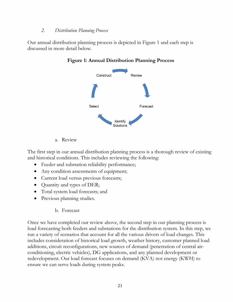
2. Distribution Planning Process
Our annual distribution planning process is depicted in Figure 1 and each step is discussed in more detail below.
Figure 1: Annual Distribution Planning Process
a. Review
The first step in our annual distribution planning process is a thorough review of existing and historical conditions. This includes reviewing the following:
• Feeder and substation reliability performance; • Any condition assessments of equipment; • Current load versus previous forecasts; • Quantity and types of DER; • Total system load forecasts; and • Previous planning studies.
b. Forecast
Once we have completed our review above, the second step in our planning process is load forecasting both feeders and substations for the distribution system. In this step, we run a variety of scenarios that account for all the various drivers of load changes. This includes consideration of historical load growth, weather history, customer planned load additions, circuit reconfigurations, new sources of demand (penetration of central air-conditioning, electric vehicles), DG applications, and any planned development or redevelopment. Our load forecast focuses on demand (KVA) not energy (KWH) to ensure we can serve loads during system peaks.
21
Then we generate a five-year forecast, aggregate the results, and compare this analysis with system projections. We then provide our distribution forecast to our transmission planning staff who incorporate the load forecast into their planning efforts. In addition to this load forecast hand off, we also communicate with internal and external transmission regularly throughout the year. Specifically, any time we become aware of larger loads or significant DG at any time of the year, we share that info with transmission. We also meet twice a year as a large group to further ensure we are each aware of plans and projects which may impact either system.
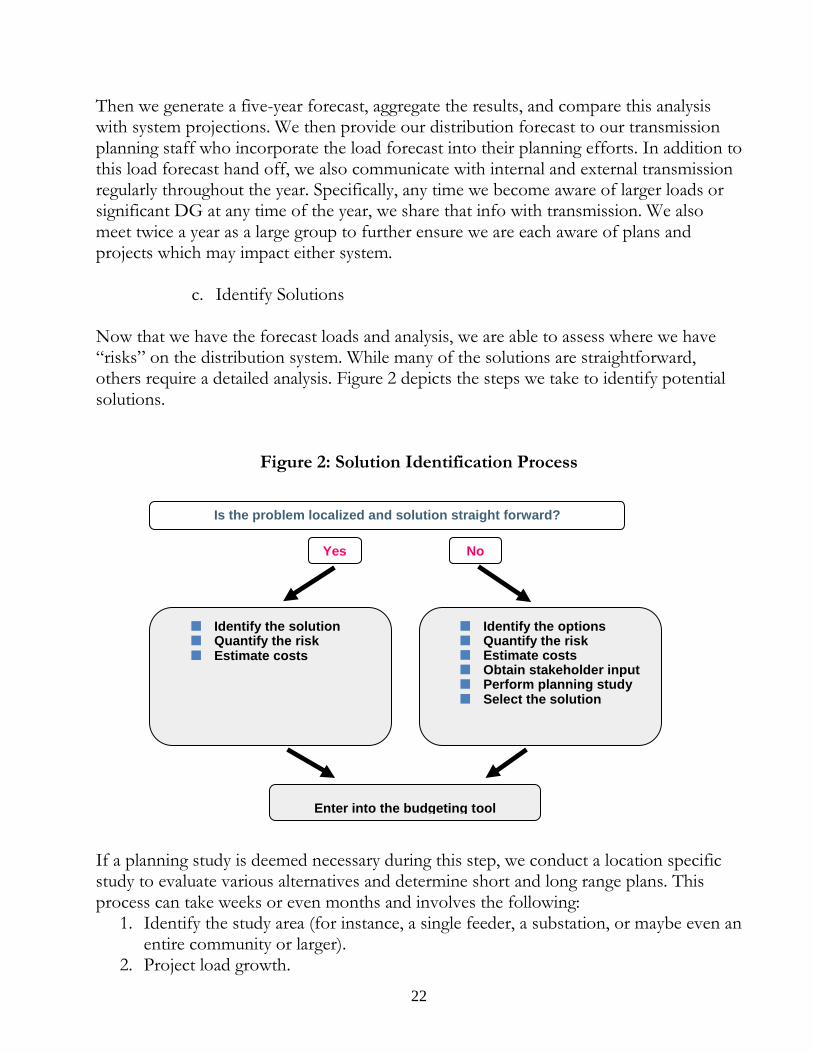
c. Identify Solutions Now that we have the forecast loads and analysis, we are able to assess where we have “risks” on the distribution system. While many of the solutions are straightforward, others require a detailed analysis. Figure 2 depicts the steps we take to identify potential solutions.
Figure 2: Solution Identification Process If a planning study is deemed necessary during this step, we conduct a location specific study to evaluate various alternatives and determine short and long range plans. This process can take weeks or even months and involves the following:
1. Identify the study area (for instance, a single feeder, a substation, or maybe even an entire community or larger).
2. Project load growth.
Identify the solution Quantify the risk Estimate costs
Identify the options Quantify the risk Estimate costs Obtain stakeholder input Perform planning study Select the solution
Yes No
Enter into the budgeting tool
Is the problem localized and solution straight forward?
22
3. Estimate the saturation of area (limits of development, zoning, etc. on load growth).
4. Coordinate with transmission planning to advise them of our work and learn if they have area concerns or projects.
5. Generate options. 6. Study and compare the economics and reliability of the alternatives.
The result of this entire step, including any necessary planning studies, is a whole slate of projects for consideration and review.
d. Select and Prioritize Solutions
Once we have all the projects identified, we weigh each investment using a risk/reward model to determine which solutions should be selected and prioritized. While we recognize that risk cannot be eliminated and funding is limited, we want to provide our customers with smart, cost-effective solutions. Accordingly, we evaluate operational risk dependent on:
• The probability of an event occurring (fault frequency, failure history of device, etc.) causing an outage; and
• The consequence of the event (amount of load unserved, number of customers, restoration time, etc.)
From this evaluation, projects are assigned a risk score, similar to a cost-benefit ratio. This is useful for comparing the merits of disparate projects. From this risk score, we select and prioritize the actual solutions we are going to move forward with.
e. Construct The final step in our annual distribution planning process is constructing the projects that have been selected from the prioritized list. The projects are organized into a five-year budget, commensurate with targeted funding levels, and then are sent to substation and distribution engineers who bring the projects to life. In summary, we will continue our efforts to identify interconnection points on our distribution system for small-scale DG resources and will provide a more comprehensive discussion in our next report. However, we do believe our current annual distribution planning process provides insight into how we address this requirement currently and assures that our planning considers factors such as necessary upgrades and reliability issues. F. Potential Variance Request As mentioned above, Minn. R. 7848.1900 provides that utilities must submit to the 23
Commission by June 1 of the year the biennial report is due a proposed notice plan to landowners and areas surrounding proposed transmission lines for which certification will be sought as part of the biennial reporting process. On June 1, 2015 there was a letter filed in this docket stating that the Minnesota Transmission Owners did not anticipate that there will be any transmission line certification requests included with the 2015 Biennial Report. While this statement is still true for the transmission projects, we do seek to certify two distribution projects but note that the June 1 deadline to file this letter was before the legislation authorizing us to file this distribution report was finalized on June 13, 2015. In addition, it is unclear whether this Minnesota Rule applies to certification for distribution projects or not. Accordingly, to the extent the Commission believes this rule may apply to distribution projects, the Company hereby requests a variance to Minnesota Rule 7848.1900. Minn. R. 7829.3200 states that the Commission shall grant a variance to its rules when it determines:
• Enforcement of the rule would impose an excessive burden upon the applicant or others affected by the rule;
• Granting the variance would not adversely affect the public interest; and • Granting the variance would not conflict with standards imposed by law.
As indicated above, we are unsure whether this Minnesota Rule applies to distribution projects or not in light of the recently amended statute. However, if the Commission determines a variance is necessary in this case, we request the Commission grant a variance, and we submit that the requirements for a variance are met here. Enforcement of Minnesota Rule 7848.1900 would impose an excessive burden on the Company as the statute authorizing a distribution certification request was not yet finalized at the time of the June 1 deadline. In addition, we do not believe granting the variance would adversely affect the public interest or conflict with any laws as distribution projects do not traditionally require a notice requirement and interested parties will have an opportunity to partake in the current docket.
CONCLUSION We appreciate the opportunity to provide this first Grid Modernization Report under the new legislation. As stated above, we view this report as preliminary and laying a framework for future planning efforts. We respectfully request certification of the following two projects: (1) Advanced Distribution Management System (ADMS) and (2) a solar plus battery storage demonstration project. In addition, if the Commission determines a variance to the notice requirements in Minnesota Rule 7848.1900 is necessary, we respectfully request the Commission grant a variance. We look forward to
24

continued dialogue with stakeholders on bringing new capabilities, functions, and technologies to the distribution grid.
October 30, 2015
25
Building Blocks
Fundamental Applications
GIS IT
InfrastructureAsset
Management Framework
Communications Infrastructure
Feeder Topology
ADMSOMS D-SCADA
Field DevicesControls Sensors
Foundational Elements 20
12-2
018
DAIVVO FLISR
Substation Automation
Advanced Metering
Infrastructure
DER (Distributed Energy
Resources)Fundamental Applications
2013
-202
0
Micro Grids
EVs(Electric Vehicles)
Energy Storage
Operational Efficiency
Dynamic Power Flow
Analytical Tools
HAN (Home Area Network) Enabled
Applications
2017
-202
3
Docket No. E999/M-15-439 Grid Modernization Report
Attachment A Page 1 of 1