bhart sanchar nigam limited
TRANSCRIPT
1
BHART SANCHAR NIGAM LIMITED
A GOVERNMENT OF ENTERPRISE
REPORT OF INDUSTRIAL TRAINING
In Partial Fulfillment of the Requirements for the Degree of
BACHELOR OF TECHNOLOGY
in
Electronics & Communication Engineering
Submitted by
Gunjan Kumar
Enrollment no. :- BT11/243
ELECTRONICS AND COMMUNICATION ENGINEERING
NIMS INSTITUTE OF ENGINEERING AND TECHNOLOGY
NIMS UNIVERSITY, SHOBHA NAGAR, JAIPUR – 303121
July-201
2
ACKNOWLEDGEMENT
IT’S A PREVILADGE TO BE ASSOCIATED WITH THE BHARAT SANCHAR NIGAM
LIMITED, BEGUSARAI (BIHAR) GOVERNMENT OF INDIA ENTERPRISE.
THIS ACKNOWLEDGEMENT IS NOT ONLY THE MEANS OF FORMALITY,BUT TO ME
IT’S A WAY BY WHICH I AM GETTING OPPOURTUNITY TO SHOW THE SENSE OF
DEEP GRATITUTE AND OBLIGATION TO ALL THE PEOPLE WHO PROVIDES ME
WITH INSPIRATION ,GUIDANCE AND HELPING DURING THIS VOCATIONAL
TRAINING AND THE PREPARATION OF THIS REPORT.
THIS TRAINING HAS BEEN SUCCESSFULLY ACCOMPLISHED DUE TO THE
CONTINUOUS OF MINE AND A VALUEABLE GUIDANCE OF THESE OF THESE
MENTIONED BELOW RENOWNED PERSONALITIES.
NAME DESIGNATION SIGNATURE
ANIL KUMAR VERMA TTA
S.C.PANDA SDE
MUKESH KUMAR SDE, EWSD
ANJANI KUMAR SDE (MS) BGS
IT IS A WONDERFULL EXPERIENCE IN WORKING WITH THIS
ORGANISATION.THANK YOU FOR BEING A VALUEABLE GUIDANCE DURING THE
ENTIRE TRAINING SESSION.
WITH SINCERE THANKS
GUNJAN KUMAR
BRANCH-ECE SIGN.OF TRAINEE
COLLEGE:-NIMS
ROLL NO- SIGN.OF TRAINER
3
PREFACE
Organizations are made up of people and function through people. Without people, organizations
cannot exist. The resources of men, money, material, machinery, and mechanism are connected,
coordinated and utilized through people. Engineers need to concentrate more on mechanism and
the way in which things have been made. The need of training arises for doing things yourself,
understanding its way.
Practical exposure for doing things makes a person conversant to the technicalities involved in
any job. In view of such benefits, imparting of vocational training has been made an integral part
of any academic structure.
In B.S.N.L., training is given to Engineering Aspirants to secure future in the dynamic world of
telecommunications. Today telecommunication industry is one of the very fastest growing
industries in the world.
In this order I have taken 28 days BSNL training. In my report I try to introduce Leased line
concepts, WIMAX, Wi-Fi, optical fiber concepts and overview of Intranet.
4
TABLE OF CONTENTS
CHAPTER
NO.
CONTENTS PAGE NO.
Cover Page 1
Acknowledgement 2
Preface 3
Contents 4-6
List of Figures 6
List of Tables 6
Chapter-1 Introduction to BSNL 7-10
1.1 Overview of BSNL 7
1.2 History 7-9
1.3 How BSNL Came to Telecom Network 9
1.4 Institutional Framework 9
1.5 BSNL Contribution to DOT 10
Chapter-2 Working of Basic Telecom network 11-14
2.1 Call Setup 11-12
2.2 Electronic Exchange 12
2.3 Carrier Room 12
2.3.1 CLLS 12
2.3.2 MLLN 12
2.4 Main Distribution Frame 13
2.4.1 Functions of MDF 14
2.5 Power Plant 14
Chapter-3 Leased Lines 15-16
3.1 Introduction 15
3.2 Drawbacks of LL 15
3.3 MLLN 15
3.3.1 MLLN Features 15-16
3.3.2 MLLN Advantages 16
3.3.3 Applications Of MLLN 16
Chapter-4 Intranet 17-19
4.1 Introduction 17
4.2 Features of Intranet 17
4.3 Why Intranet for an Organization? 17
4.4 Application of Intranet 18
4.5 Overview of Intranet 18
4.6 Intranet Application in a Circle 19
Chapter-5 Corporate Network 20-21
5.1 Introduction 20
5.2 Why do Organization have CN? 20-21
5.3 Features of CN Security 21
Chapter-6 WI-FI 22-23
6.1 WI-FI Network 22
5
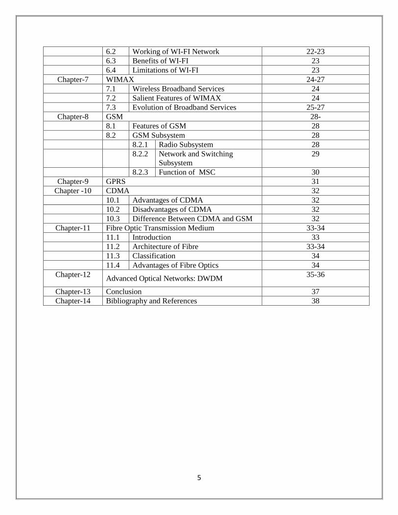
6.2 Working of WI-FI Network 22-23
6.3 Benefits of WI-FI 23
6.4 Limitations of WI-FI 23
Chapter-7 WIMAX 24-27
7.1 Wireless Broadband Services 24
7.2 Salient Features of WIMAX 24
7.3 Evolution of Broadband Services 25-27
Chapter-8 GSM 28-
8.1 Features of GSM 28
8.2 GSM Subsystem 28
8.2.1 Radio Subsystem 28
8.2.2 Network and Switching
Subsystem
29
8.2.3 Function of MSC 30
Chapter-9 GPRS 31
Chapter -10 CDMA 32
10.1 Advantages of CDMA 32
10.2 Disadvantages of CDMA 32
10.3 Difference Between CDMA and GSM 32
Chapter-11 Fibre Optic Transmission Medium 33-34
11.1 Introduction 33
11.2 Architecture of Fibre 33-34
11.3 Classification 34
11.4 Advantages of Fibre Optics 34
Chapter-12 Advanced Optical Networks: DWDM
35-36
Chapter-13 Conclusion 37
Chapter-14 Bibliography and References 38
6
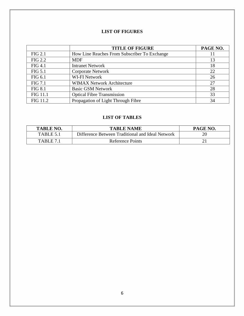
LIST OF FIGURES
TITLE OF FIGURE PAGE NO.
FIG 2.1 How Line Reaches From Subscriber To Exchange 11
FIG 2.2 MDF 13
FIG 4.1 Intranet Network 18
FIG 5.1 Corporate Network 22
FIG 6.1 WI-FI Network 26
FIG 7.1 WIMAX Network Architecture 27
FIG 8.1 Basic GSM Network 28
FIG 11.1 Optical Fibre Transmission 33
FIG 11.2 Propagation of Light Through Fibre 34
LIST OF TABLES
TABLE NO. TABLE NAME PAGE NO.
TABLE 5.1 Difference Between Traditional and Ideal Network 20
TABLE 7.1 Reference Points 21
7
CHAPTER-1
INTRODUCTION TO BSNL
India is the fourth largest telecom market in Asia after China, Japan and South Korea. The Indian
telecom network is the eighth largest in the world.
TYPE: COMMUNICATION SERVICE PROVIDER
COUNTRY: INDIA
AVAILABLITY: NATIONAL EXCEPT DELHI & MUMBAI
OWNER: THE GOVERNMENT OF INDIA
WEBSITE: www.bsnl.co.in
1.1 OVERVIEW OF THE BSNL BSNL is India’s oldest and largest Communication Service Provider (CSP).Currently BSNL has
a customer base of 64.8 million (Basic & Mobile telephony). It has footprints throughout India
except for the metropolitan cities of Mumbai and New Delhi which are managed by MTNL. As
on March 31, 2010 BSNL commanded a customer base of 33.7 million Wire line, 3.6 million
CDMA-WLL and 27.5 million GSM Mobile subscribers. BSNLs earnings for the Financial Year
ending March 31, 2010 stood at INR 401.8b (US$ 9.09 b) with net profit of INR 89.4b (US$
2.02 billion). Today, BSNL is India’s largest Telco and one of the largest Public Sector
Undertaking of the country with authorized share capital of US$ 3.95 billion (INR 17,500
Crores) and net worth of US$14.32 billion.
1.2 HISTORY
BSNL, then known as the Department of Telecommunications, had been a near monopoly during
the socialist period of the Indian economy. During this period, BSNL was the only telecom
service provider in the country. MTNL was present only in Mumbai and New Delhi. During this
period BSNL operated as a typical state-run organization, inefficient, slow, bureaucratic, and
heavily unionized. As a result subscribers had to wait for as long as five years to get a telephone
connection. The corporation tasted competition for the first time after the liberalization of Indian
economy in 1991. Faced with stiff competition from the private telecom service providers,
BSNL has subsequently tried to increase efficiencies itself. DOT veterans, however, put the onus
for the sorry state of affairs on the Government policies, where in all state-owned service
providers were required to function as mediums for achieving egalitarian growth across all
segments of the society. The corporation (then DOT), however, failed to achieve this and India
languished among the most poorly connected countries in the world. BSNL was born in 2000
after the corporatization of DOT. The corporatization of BSNL was undertaken by an external
international consulting team consisting of a consortium of A.F.Ferguson & Co, JB Dadachanji
and NM Rothschild - and was probably the most complex corporatization exercise of its kind
ever attempted anywhere because of the quantum of assets (said to be worth USD 50 Billion in
terms of breakup value) and over half a million directly and indirectly employed staff. Satish
8
Mehta, who led the team later confessed that one big mistake made by the consortium was to
recommend the continuation of the state and circle based geographical units which may have
killed the synergies across regions and may have actually made the organization less efficient
than had it been a seamless national organization. Vinod Vaish, then Chairman of the Telecom
Commission made a very bold decision to promote younger talent from within the organization
to take up a leadership role and promoted the older leaders to a role in licensing rather than in
managing the operations of BSNL. The efficiency of the company has since improved,however,
the performance level is nowhere near the private players.
The corporation remains heavily unionised and is comparatively slow in decision making and its
implementation, which largely acts at the instances of unions without bothering about outcome.
Management has been reactive to the schemes of private telecom players. Though it offers
services at lowest tariffs, the private players continue to notch up better numbers in all areas,
years after year. BSNL has been providing connections in both urban and rural areas. Pre-
activated Mobile connections are available at many places across India. BSNL has also unveiled
cost-effective broadband internet access plans (Data One) targeted at homes and small
businesses. At present BSNL enjoys around 60% of market share of ISP services.
Year of Broadband 2007
2007 was declared as "Year of Broadband" in India and BSNL announced plans for providing 5
million broadband connectivity by the end of 2007. BSNL upgraded Dataone connections for a
speed of up to 2 Mbit/s without any extra cost. This 2 Mbit/s broadband service was provided by
BSNL at a cost of just US$ 11.7 per month (as of 21 July 2008 and at a limit of 2.5GB monthly
limit with 0200-0800 hrs as no charge period). Further, BSNL is rolling out new broadband
services such as triple play.BSNL planned to increase its customer base to 108 million customers
by 2010. With the frantic activity in the communication sector in India, the target appears
achievable.
BSNL is a pioneer of rural telephony in India. BSNL has recently bagged 80% of US$ 580 m
(INR 25 billion) Rural Telephony project of Government of India.
On 20 March 2009 BSNL advertised the launch of BlackBerry services across its Telecom
circles in India. The corporation has also launched 3G services in select cities across the country.
Presently, BSNL and MTNL are the only players to provide 3G services, as the Government of
India has completed auction of 3G services for private players. BSNL shall get 3G bandwidth at
lowest bidder prices of Rs 185 billion, which includes Rs 101.86 billion for 3G and Rs
83.13 billion for BWA.
As of December 2011, many other private operators have started rolling out their 3rd Generation
(aka 3G) services alongside and are enjoying some success in their campaigns to get market
share. While BSNL still maintains its connectivity standard and expands to many more areas
including rural areas with their 3G services. Also the network infrastructure has been upgraded
9
from to provide 3.6 Mbit/s to 7.2 MBits/sec. It is enjoying a slow but somewhat steady success in
gaining market share in this regard.
The introduction of MNP(Mobile Number Portability) which is an service that lets the consumer
change wireless service providers while retaining their actual mobile number, BSNL has seen
many customers opting for this service to move away from the services to other operators.
Despite this as the Indian Wireless market grows BSNL still has a loyal base of subscribers and
many more subscribers being added to it every day. This provides customer services for 95
million as of June 2011.
BSNL announced the discontinuation of its telegram services from 15 July 2013, after 160 years
in service. It was opened to the public in February 1855; in 2010 it was upgraded to a web-based
messaging system in 2010, through 182 telegraph offices across India.
1.3 HOW BSNL CAME IN TELECOM MARKET:
The initial phase of telecom reforms began in 1984 with the creation of Center for Department of
Telematics (C-DOT) for developing indigenous technologies and private manufacturing of
customer premise equipment. Soon after, the Mahanagar Telephone Nigam Limited (MTNL) and
Videsh Sanchar Nigam Limited (VSNL) were set up in 1986.The Telecom Commission was
established in 1989. A crucial aspect of the institutional reform of the Indian telecom sector was
setting up of an independent regulatory body in 1997 – the Telecom Regulatory Authority of
India (TRAI), to assure investors that the sector would be regulated in a balanced and fair
manner. In 2000, DoT corporatized its services wing and created Bharat Sanchar Nigam Limited.
1.4 INSTITUTIONAL FRAMEWORK:
It is defined as the system of formal laws, regulations, and procedures, and informal conventions,
customs, and norms, that broaden, mold, and restrain socio-economic activity and behavior. The
country has been divided into units called Circles, Metro Districts, Secondary Switching Areas
(SSA), Long Distance Charging Area (LDCA) and Short Distance Charging Area (SDCA).
In India, DoT is the nodal agency for taking care of telecom sector on behalf of government.
Its basic functions are:
Policy Formulation
Review of performance
Licensing
Wireless spectrum management
Administrative monitoring of PSUs
Research & Development
Standardization/Validation of Equipment
10
1.5 BSNL CONTRIBUTION TO DEVELOPMENT OF TELECOM:
Bharat Sanchar Nigam Limited was formed in year 2000 and took over the service
providers role from DOT. BSNL’s roadmap for providing customer with access to the latest
telecommunications services without losing sight of universal service access has been by way of
utilizing optimally the existing infrastructure and accelerating advances in technological
component by innovative absorption.
ACHIEVEMENTS OF BSNL:
BSNL has a customer base of over 9 crore and is the fourth largest integrated telecom
operator in the country.
BSNL is the market leader in Broadband, landline and national transmission network.
BSNL is also the only operator covering over 5 lakh village with telecom connectivity.
Area of operation of BSNL is all India except Delhi & Mumbai.
11
CHAPTER-2
WORKING OF BASIC TELECOMMUNICATION NETWORK
This section includes brief introduction of how a call is processed when we dial a call from basic
telephone to another basic telephone or from basic to mobile or vice versa.
2.1 CALL SETUP:
When a subscriber calls to another subscriber first its request goes to the nearest switching
centre that is PSTN (Public Switching Telecommunication Network). Then it processes the
caller and subscriber’s number if it exists in the same BSC then call setup is completed.
If subscriber is not in the same BSC (Base Switching Centre) then call transfer to MSC
(Main Switching Centre) then it transfers the call to prior BSC then call setup is completed.
If Caller calls to a mobile subscriber then call transfer is done by MTSO now call transfer is
done on BTSs (Base Transceiver Station) and call setup is completed.
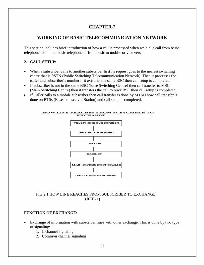
FIG 2.1 HOW LINE REACHES FROM SUBSCRIBER TO EXCHANGE
(REF- 1)
FUNCTION OF EXCHANGE:
Exchange of information with subscriber lines with other exchange. This is done by two type
of signaling:
1. Inchannel signaling
2. Common channel signaling
12
Processing of signaling information and controlling the operation of signaling network.
Charging and billing.
2.2 ELECTRONIC EXCHANGE:
All control functions by series of instructions are stored in memory.
Memories are modifiable and control program can always be rewritten. For each call
processing step decision is taken according to class of service.
2.3 CARRIER ROOM:
Leased line connectivity is provided in carrier room. This room has two parts:
1. Conventional leased line system
2. MLLN
2.3.1 CONVENTIONAL LEASED LINE SYSTEM:
It consists of modems and routers that are provided by the company requesting for that
network.
Connectivity of different ATM, banks etc. is provided by BSNL here.
For this, we have 4 modems (2 in Exchange, 1 at sender and 1 at receiver)
Modems are used for short distances i.e. trans and receive part are received here and local
lead connection is given to the subscriber.
Local lead faults can be handled here but the trans and receive faults can be handled by the
department meant for it.
Accept 64Kbps or 2 Mbps.
For long distance communication we have MUXS and data is sent through optical fibers.
MUXS are present at both the ends.
2.3.2 MANAGED LEASED LINE NETWORK:
No open wiring.
Route can be changed by the computer software
In Agra Gate Exchange, we have 3 VMUX of type II.
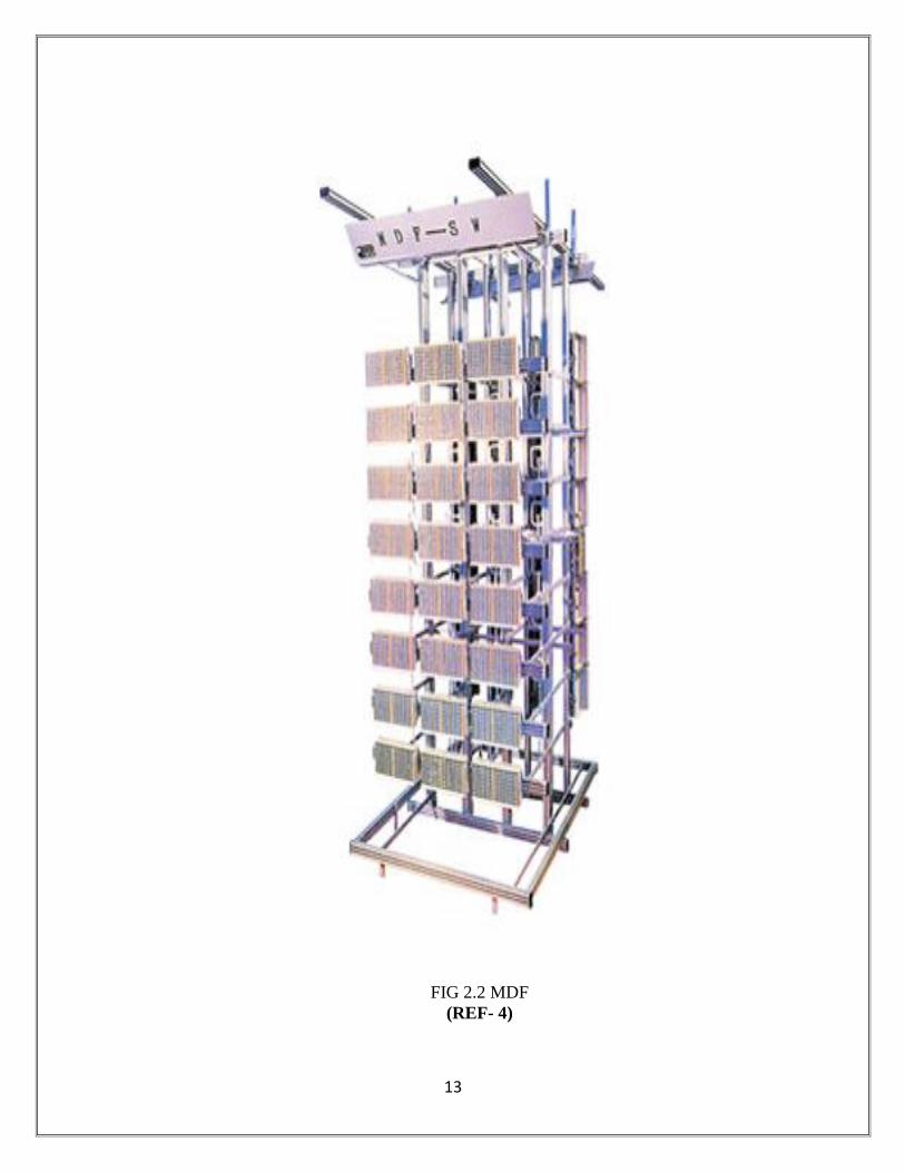
2.4 MDF(MAIN DISTRIBUTION FRAME):
M.D.F. is a media between switching network and subscriber’s line. It is a termination point
within the local telephone exchange where exchange equipment and terminations of local loops
are connected by jumper wires.
13
FIG 2.2 MDF
(REF- 4)

14
2.4.1 FUNCTIONS OF MDF:
All cable copper wires supplying services through user telephone lines are terminated and
distributed through MDF.
The most common kind of large MDF is a long steel rack accessible from both sides. Each
jumper is a twisted wire.
It consists of local connection and broadband connection frames for the main Exchange area.
The MDF usually holds central office protective devices including heat coils and functions as
a test point between a line and the office.
It provides testing of calls.
It checks whether fault is indoor or external.
All lines terminate individually.
2.5 POWER PLANT:
It provides -48V to the switch rooms and 48V to the connections.
Batteries are artificially discharged once in a year for their maintenance.
Cooling is provided through fans & AC.
There is earth region too for protection.
15
CHAPTER-3
LEASED LINES
3.1 INTRODUCTION:
A leased line (dedicated line) is a permanent fiber optic or telephone connection between two
points set up by a telecommunications carrier. They can be used for telephone, data, or Internet
services. Businesses use a leased line to connect to geographically distant offices because it
guarantees bandwidth for network traffic. For example, a bank may use a leased line in order to
easily transfer financial information from one office to another. Customers generally pay a flat
monthly rate for the service depending on the distance between the two points. Leased lines do
not have telephone numbers. The information sent through the leased line travels along dedicated
secure channels, eliminating the congestion that occurs in shared networks.
3.2 DRAWBACKS OF TRADITIONAL LEASED LINE CIRCUITS:
1. Limited range of services - Only Plain Leased Line Service, Data cards support only up
to 64 kbps, no support for N x 64 Kbps.
2. From Operator point of view in case of Leased Line Circuit different boxes from different
vendors so difficult to manage & control.
3. No Centralized Monitoring or alarm or performance monitoring.
The solution to this is MLLN.
3.3 MLLN ( MANAGED LEASED LINE NETWORK ):
The MLLN service is specially designed mainly for having effective control and monitoring on
the leased line so that the down time is minimized and the circuit efficiency is increased. This
mainly deals with data circuits ranging from 64 Kbps to 2048 Kbps.
3.3.1 MLLN FEATURES:
1. MLLN is an integrated, fully managed, multi service digital network platform through
which service provider can offer a wide range of service at an optimal cost to business
subscriber.
2. Using NMS, MLLN can provide high speed Leased Line with improved QoS, high
availability & reliability.
3. Except for connecting the local lead to the MODEM all operations & maintenance is
carried out through ROT (Remote Operating Terminal).
16
4. NMS supports service provisioning, Network optimization, planning & service monitering.
5. System offers end to end circuit creation and modification, circuit loop testing & fault
isolation, automatic rerouting of traffic in case of trunk failure, software programmability
of NTU etc.
6. Banking, Financial institution, Stock market, paper industry, broadcasting & Internet
service Provider are the main customers for MLLN.
3.3.2 MLLN ADVANTAGES:
1. 24 hrs Performance Monitoring of the circuit.
2. Circuit fault reports generated proactively.
3. On Demand the Bandwidth can be increased.
4. Low lead time for new circuit provisioning.
5. Protection against the failure of the circuit through recovery Management process either
automatic or manually.
6. Long drive on single copper pair.( for 64 kbps – 7 kms & for 2mbps – 3.5 kms)
7. Centrally managed from ROT connected to the NMS.
3.3.3 APPLICATION OF MLLN:
1. Corporate high speed internet access through Broadband.
2. LAN interconnection.
3. Hotline connectivity for voice.
4. Point to point connection for data circuit.
5. Point to multipoint connection.
17
CHAPTER-4
INTRANET
4.1 INTRANET:
Smaller private version of Internet. It uses Internet protocols to create enterprise-wide
network which may consists of interconnected LANs.
It may or may not include connection to Internet.
Intranet is an internal information system based on Internet technology and web protocols
for implementation within a corporate organization.
This implementation is performed in such a way as to transparently deliver the immense
informational resources of an organization to each individual’s desktop with minimal cost,
time and effort.
The Intranet defines your organization and displays it for everyone to see.
4.2 FEATURES OF INTRANET:
1. It is scalable.
2. It is Interchangeable.
3. It is platform independent
4. It is Hardware independent.
5. It is vendor independent.
4.3 WHY INTRANET FOR AN ORGANIZATION:
Quick access to voice, video, data and other resources needed by users.
Variety of valuable Intranet applications improves communication and productivity across
all areas of an enterprise.
A 21st Century Telephone.
An ISO Tool.
A Target Marketing Tool.
A Decision Making Tool.
A Complete Communication Tool.
18
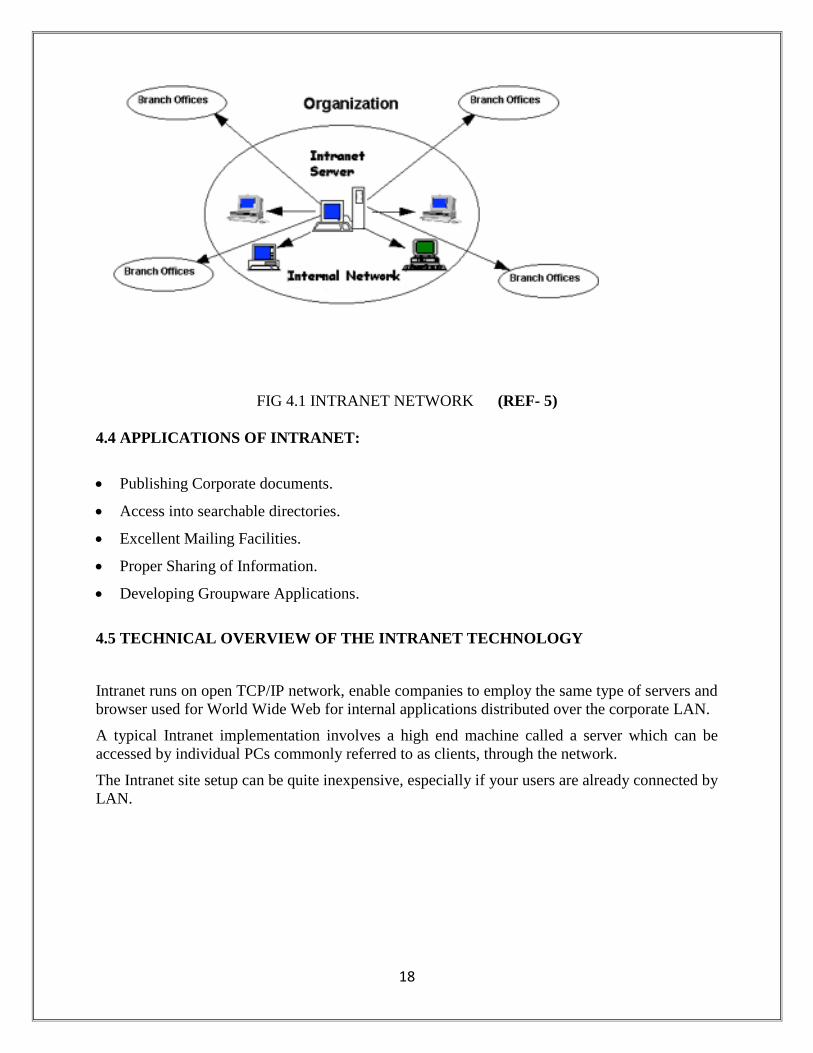
FIG 4.1 INTRANET NETWORK (REF- 5)
4.4 APPLICATIONS OF INTRANET:
Publishing Corporate documents.
Access into searchable directories.
Excellent Mailing Facilities.
Proper Sharing of Information.
Developing Groupware Applications.
4.5 TECHNICAL OVERVIEW OF THE INTRANET TECHNOLOGY
Intranet runs on open TCP/IP network, enable companies to employ the same type of servers and
browser used for World Wide Web for internal applications distributed over the corporate LAN.
A typical Intranet implementation involves a high end machine called a server which can be
accessed by individual PCs commonly referred to as clients, through the network.
The Intranet site setup can be quite inexpensive, especially if your users are already connected by
LAN.
19
4.6 INTRANET APPLICATIONS IN A CIRCLE:
Every circle must have an intranet server which should have the following:
All posting/transfer/relieving orders issued within circle to be hosted on the intranet.
All letters circulars/letters issued from different sections of the circle office to be hosted on
the server for immediate access by SSAs. Each section in circle office Administration,
Operations, Marketing, Finance, Planning, Computers etc can have web pages hosted on the
server.
A database can be maintained for MIS reports and all other reports to be sent periodically by
SSAs to circle office. The database can have front end forms designed in ASP or PHP for
the SSAs to input the data. Separate programs can be developed to consolidate the data fed
by SSAs.
All data prepared and /or distributed during SSA heads meetings can be hosted on the
Intranet.
The implementation of the above will reduce the usage of paper and also reduce the usage of
FAX.
20
CHAPTER-5
CORPORATE NETWORK
5.1 INTRODUCTION:
A corporate network (CN) is a closed and private computer network that affords secure
communications between geographically dispersed LANs of an enterprise.
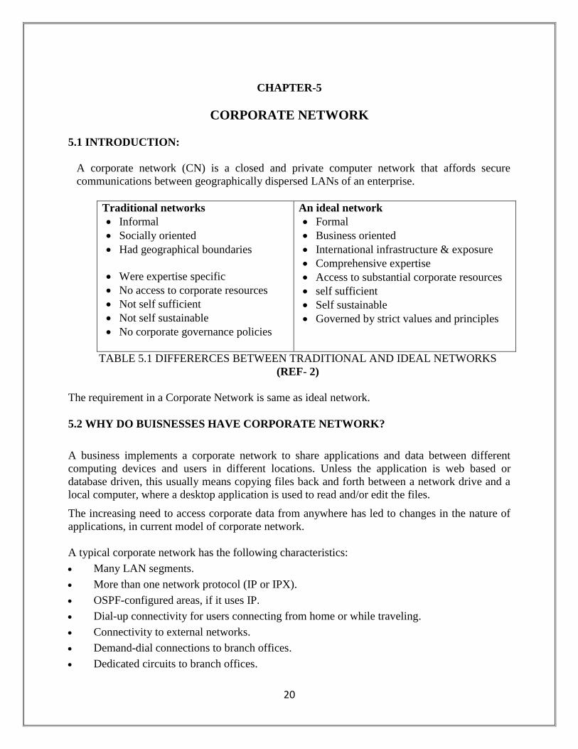
Traditional networks
Informal
Socially oriented
Had geographical boundaries
Were expertise specific
No access to corporate resources
Not self sufficient
Not self sustainable
No corporate governance policies
An ideal network
Formal
Business oriented
International infrastructure & exposure
Comprehensive expertise
Access to substantial corporate resources
self sufficient
Self sustainable
Governed by strict values and principles
TABLE 5.1 DIFFERERCES BETWEEN TRADITIONAL AND IDEAL NETWORKS
(REF- 2)
The requirement in a Corporate Network is same as ideal network.
5.2 WHY DO BUISNESSES HAVE CORPORATE NETWORK?
A business implements a corporate network to share applications and data between different
computing devices and users in different locations. Unless the application is web based or
database driven, this usually means copying files back and forth between a network drive and a
local computer, where a desktop application is used to read and/or edit the files.
The increasing need to access corporate data from anywhere has led to changes in the nature of
applications, in current model of corporate network.
A typical corporate network has the following characteristics:
Many LAN segments.
More than one network protocol (IP or IPX).
OSPF-configured areas, if it uses IP.
Dial-up connectivity for users connecting from home or while traveling.
Connectivity to external networks.
Demand-dial connections to branch offices.
Dedicated circuits to branch offices.
21
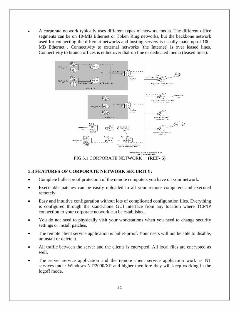
A corporate network typically uses different types of network media. The different office
segments can be on 10-MB Ethernet or Token Ring networks, but the backbone network
used for connecting the different networks and hosting servers is usually made up of 100-
MB Ethernet . Connectivity to external networks (the Internet) is over leased lines.
Connectivity to branch offices is either over dial-up line or dedicated media (leased lines).
FIG 5.1 CORPORATE NETWORK (REF- 5)
5.3 FEATURES OF CORPORATE NETWORK SECURITY:
Complete bullet-proof protection of the remote computers you have on your network.
Executable patches can be easily uploaded to all your remote computers and executed
remotely.
Easy and intuitive configuration without lots of complicated configuration files. Everything
is configured through the stand-alone GUI interface from any location where TCP/IP
connection to your corporate network can be established.
You do not need to physically visit your workstations when you need to change security
settings or install patches.
The remote client service application is bullet-proof. Your users will not be able to disable,
uninstall or delete it.
All traffic between the server and the clients is encrypted. All local files are encrypted as
well.
The server service application and the remote client service application work as NT
services under Windows NT/2000/XP and higher therefore they will keep working in the
logoff mode.
22
CHAPTER-6
WI-FI (WIRELESS FIDELITY)
6.1 WI-FI NETWORK:
A Wi-Fi network provides the features and benefits of traditional LAN technologies such as
Ethernet and Token Ring without the limitations of wires or cables. It provides the final few
meters of connectivity between a wired network and the mobile user. WIFI is a wireless LAN
Technology to deliver wireless broad band speeds up to 54 Mbps to Laptops, PCs, PDAs, dual
mode Wi-Fi enabled phones etc.
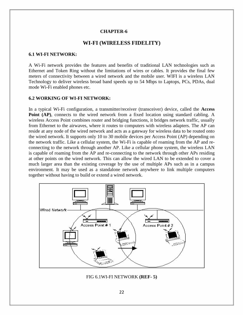
6.2 WORKING OF WI-FI NETWORK:
In a typical Wi-Fi configuration, a transmitter/receiver (transceiver) device, called the Access
Point (AP), connects to the wired network from a fixed location using standard cabling. A
wireless Access Point combines router and bridging functions, it bridges network traffic, usually
from Ethernet to the airwaves, where it routes to computers with wireless adapters. The AP can
reside at any node of the wired network and acts as a gateway for wireless data to be routed onto
the wired network. It supports only 10 to 30 mobile devices per Access Point (AP) depending on
the network traffic. Like a cellular system, the Wi-Fi is capable of roaming from the AP and re-
connecting to the network through another AP. Like a cellular phone system, the wireless LAN
is capable of roaming from the AP and re-connecting to the network through other APs residing
at other points on the wired network. This can allow the wired LAN to be extended to cover a
much larger area than the existing coverage by the use of multiple APs such as in a campus
environment. It may be used as a standalone network anywhere to link multiple computers
together without having to build or extend a wired network.
FIG 6.1WI-FI NETWORK (REF- 5)
23
End users access the Wi-Fi network through Wi-Fi adapters, which are implemented as cards in
desktop computers, or integrated within hand-held computers. Wi-Fi wireless LAN adapters
provide an interface between the client Network Operating System (NOS) and the airwaves via
an antenna.
6.3 BENEFITS OF WI-FI:
Wi-Fi offers the following productivity, conveniences, and cost advantages over traditional
wired networks:
Mobility: Wi-Fi systems can provide LAN users with access to real-time information
anywhere in their organization.
Installation Speed and Simplicity: Installing a Wi-Fi system can be fast and easy and can
eliminate the need to pull cable through walls and ceilings.
Installation Flexibility: Wireless technology allows the network to go where wire cannot
go.
Reduced Cost-of-Ownership: While the initial investment required for Wi-Fi hardware can
be higher than the cost of wired LAN hardware, overall installation expenses and life-cycle
costs can be significantly lower.
Scalability: Wi-Fi systems can be configured in a variety of topologies to meet the needs of
specific applications and installations. Configurations are easily changed and range from
peer-to-peer networks suitable for a small number of users to full infrastructure networks of
thousands of users that allows roaming over a broad area.
It offers much high speed up to 54 Mbps which is very much greater than other wireless
access technologies like CORDECT, GSM and CDMA.
6.4 LIMITATIONS OF WI-FI:
Coverage: A single Access Point can cover, at best, a radius of only about 60 meters. For
10 square kms area roughly 650 Access Points are required, where as CDMA 2000 1xEV-
DO requires just 09 sites.
Roaming: It lacks roaming between different networks hence wide spread coverage by one
service provider is not possible, which is the key to success of wireless technology.
Backhaul: Backhaul directly affects data rate service. Wi-Fi real world data rates are at
least half of the their theoretical peak rates due to factors such as signal strength,
interference and radio overhead .Backhaul reduces the remaining throughput further.
Interference: Wi-Fi uses unlicensed spectrum, which mean no regulator recourse against
interference. The most popular type of Wi-Fi, ‘802.11’b uses.
24
CHAPTER-7
WIMAX
7.1 WIRELESS BROADBAND SERVICES:
There are two fundamentally different types of broadband wireless services. The first type
attempts to provide a set of services similar to that of the traditional fixed-line broadband but
using wireless as the medium of transmission. This type, called fixed wireless broadband, can be
thought of as a competitive alternative to DSL or cable modem. The second type of broadband
wireless, called mobile broadband, offers the additional functionality of portability, nomadicity
and mobility.
WI-MAX is an acronym that stands for World-wide Interoperability for Microwave Access
and this technology is designed to accommodate both fixed and mobile broadband applications.
7.2 SALIENT FEATURES OF WIMAX:
OFDM-based physical layer.
Very high peak data rates.
Scalable bandwidth and data rate support.
Adaptive modulation and coding (AMC).
Link-layer retransmissions.
Support for TDD and FDD OFDMA.
Flexible and dynamic per user resource allocation.
Support for advanced antenna techniques.
Quality-of-service support.
Robust security.
Support for mobility.
IP-based architecture.
25
7.3 EVOLUTION OF BROADBAND WIRELESS:
1. NARROWBAND WIRELESS LOCAL-LOOP SYSTEMS: The first application for which a
wireless alternative was developed and deployed was voice telephony. These systems, called
wireless local-loop (WLL). WLL systems based on the digital-enhanced cordless telephony
(DECT) and code division multiple access (CDMA) standards continue to be deployed in these
markets. During the same time, several small start-up companies focused solely on providing
Internet-access services using wireless, antennas to be installed at the customer premises. These
early systems typically offered speeds up to a few hundred kilobits per second. Later evolutions
of license-exempt systems were able to provide higher speeds.
2. FIRST-GENERATION BROADBAND SYSTEMS: As DSL and cable modems began to be
deployed, wireless systems had to evolve to support much higher speeds to be competitive. Very
high speed systems, called local multipoint distribution systems (LMDS), supporting up to
several hundreds of megabits per second, were developed.
In the late 1990s, one of the more important deployments of wireless broadband happened in the
so-called multi channel multipoint distribution services (MMDS) band at 2.5GHz. The MMDS
band was historically used to provide wireless cable broadcast video services, especially in rural
areas where cable TV services were not available. The first generations of these fixed broadband
wireless solutions were deployed using the same towers that served wireless cable subscribers.
These towers were typically several hundred feet tall and enabled LOS coverage to distances up
to 35 miles, using high-power transmitter.
The advent of satellite TV ruined the wireless cable business, and operators were looking for
alternative ways to use this spectrum. A few operators began to offer one-way wireless Internet-
access service, using telephone line as the return path.
3. SECOND - GENERATION BROADBAND SYSTEMS: Second-generation broadband
wireless systems were able to overcome the LOS issue and to provide more capacity. This was
done through the use of a cellular architecture and implementation of advanced-signal processing
techniques to improve the link and system performance under multi path conditions. Many
solved the NLOS problem by using such techniques as orthogonal frequency division
multiplexing (OFDM), code division multiple access (CDMA), and multi antenna processing.
4. WIMAX AND OTHER BROADBAND WIRELESS TECHNOLOGIES:
WIMAX is not the only solution for delivering broadband wireless services. WiMAX occupies a
somewhat middle ground between Wi-Fi and 3G technologies when compared in the key
dimensions of data rate, coverage, QoS, mobility, and price.
WIMAX NETWORK ARCHITECTURE:
The overall network may be logically divided into three parts:
1. Mobile Stations (MS) used by the end user to access the network.
26
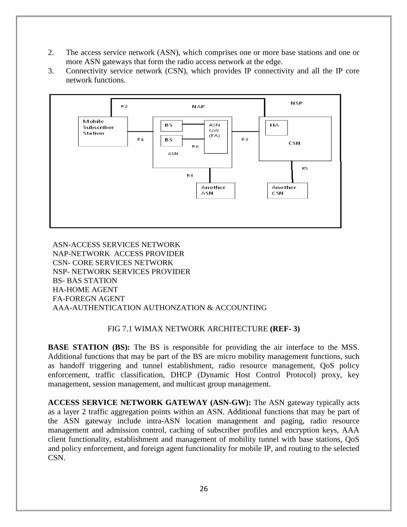
2. The access service network (ASN), which comprises one or more base stations and one or
more ASN gateways that form the radio access network at the edge.
3. Connectivity service network (CSN), which provides IP connectivity and all the IP core
network functions.
FIG 7.1 WIMAX NETWORK ARCHITECTURE (REF- 3)
BASE STATION (BS): The BS is responsible for providing the air interface to the MSS.
Additional functions that may be part of the BS are micro mobility management functions, such
as handoff triggering and tunnel establishment, radio resource management, QoS policy
enforcement, traffic classification, DHCP (Dynamic Host Control Protocol) proxy, key
management, session management, and multicast group management.
ACCESS SERVICE NETWORK GATEWAY (ASN-GW): The ASN gateway typically acts
as a layer 2 traffic aggregation points within an ASN. Additional functions that may be part of
the ASN gateway include intra-ASN location management and paging, radio resource
management and admission control, caching of subscriber profiles and encryption keys, AAA
client functionality, establishment and management of mobility tunnel with base stations, QoS
and policy enforcement, and foreign agent functionality for mobile IP, and routing to the selected
CSN.
ASN-ACCESS SERVICES NETWORK
NAP-NETWORK ACCESS PROVIDER
CSN- CORE SERVICES NETWORK
NSP- NETWORK SERVICES PROVIDER
BS- BAS STATION
HA-HOME AGENT
FA-FOREGN AGENT
AAA-AUTHENTICATION AUTHONZATION & ACCOUNTING
27
CONNECTIVITY SERVICE NETWORK (CSN): The CSN provides connectivity to the
Internet, ASP, other public networks, and corporate networks. The CSN is owned by the NSP
and includes AAA servers that support authentication for the devices, users, and specific
services. The CSN also provides per user policy management of QoS and security. The CSN is
also responsible for IP address management, support for roaming between different NSPs,
location management between ASNs, and mobility and roaming between ASNs, subscriber
billing and inter operator settlement, inter-CSN tunneling to support roaming between different
NSPs.
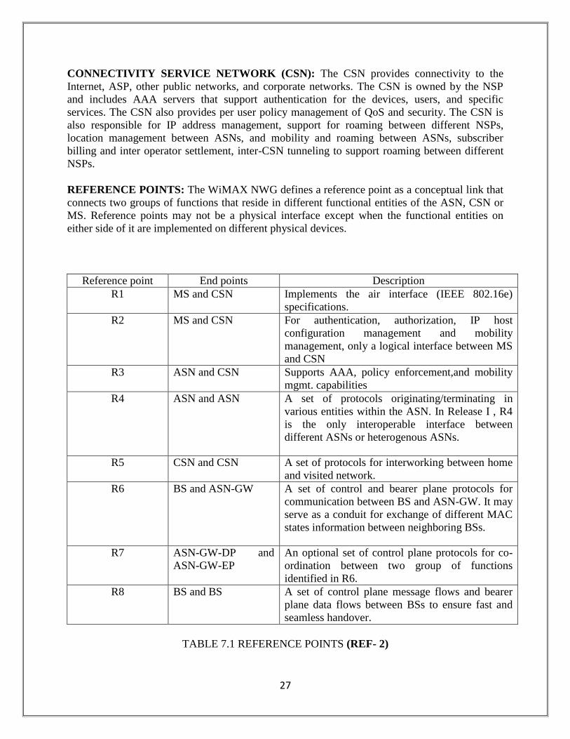
REFERENCE POINTS: The WiMAX NWG defines a reference point as a conceptual link that
connects two groups of functions that reside in different functional entities of the ASN, CSN or
MS. Reference points may not be a physical interface except when the functional entities on
either side of it are implemented on different physical devices.
Reference point End points Description
R1 MS and CSN Implements the air interface (IEEE 802.16e)
specifications.
R2 MS and CSN For authentication, authorization, IP host
configuration management and mobility
management, only a logical interface between MS
and CSN
R3 ASN and CSN Supports AAA, policy enforcement,and mobility
mgmt. capabilities
R4 ASN and ASN A set of protocols originating/terminating in
various entities within the ASN. In Release I , R4
is the only interoperable interface between
different ASNs or heterogenous ASNs.
R5 CSN and CSN A set of protocols for interworking between home
and visited network.
R6 BS and ASN-GW A set of control and bearer plane protocols for
communication between BS and ASN-GW. It may
serve as a conduit for exchange of different MAC
states information between neighboring BSs.
R7 ASN-GW-DP and
ASN-GW-EP
An optional set of control plane protocols for co-
ordination between two group of functions
identified in R6.
R8 BS and BS A set of control plane message flows and bearer
plane data flows between BSs to ensure fast and
seamless handover.
TABLE 7.1 REFERENCE POINTS (REF- 2)
28
CHAPTER-8
GLOBAL SYSTEM FOR MOBILE COMMUNICATION (GSM)
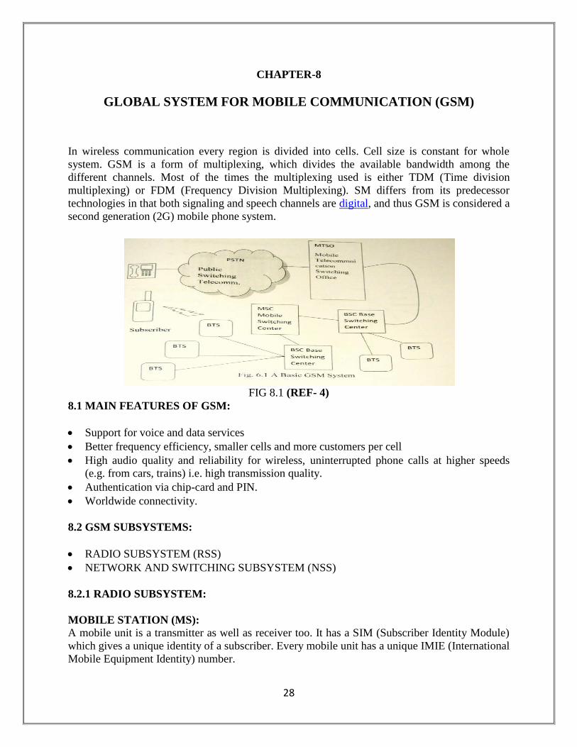
In wireless communication every region is divided into cells. Cell size is constant for whole
system. GSM is a form of multiplexing, which divides the available bandwidth among the
different channels. Most of the times the multiplexing used is either TDM (Time division
multiplexing) or FDM (Frequency Division Multiplexing). SM differs from its predecessor
technologies in that both signaling and speech channels are digital, and thus GSM is considered a
second generation (2G) mobile phone system.
FIG 8.1 (REF- 4)
8.1 MAIN FEATURES OF GSM:
Support for voice and data services
Better frequency efficiency, smaller cells and more customers per cell
High audio quality and reliability for wireless, uninterrupted phone calls at higher speeds
(e.g. from cars, trains) i.e. high transmission quality.
Authentication via chip-card and PIN.
Worldwide connectivity.
8.2 GSM SUBSYSTEMS:
RADIO SUBSYSTEM (RSS)
NETWORK AND SWITCHING SUBSYSTEM (NSS)
8.2.1 RADIO SUBSYSTEM:
MOBILE STATION (MS):
A mobile unit is a transmitter as well as receiver too. It has a SIM (Subscriber Identity Module)
which gives a unique identity of a subscriber. Every mobile unit has a unique IMIE (International
Mobile Equipment Identity) number.
29
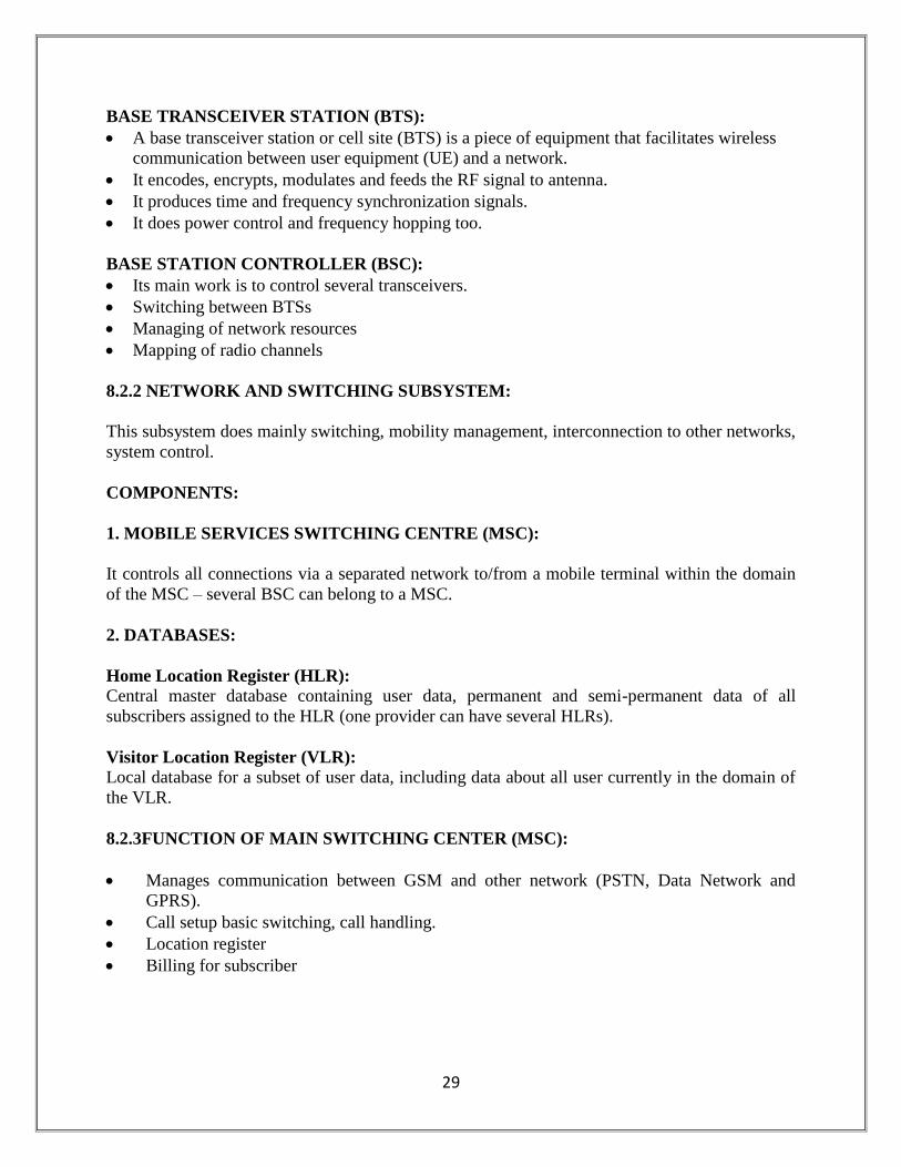
BASE TRANSCEIVER STATION (BTS):
A base transceiver station or cell site (BTS) is a piece of equipment that facilitates wireless
communication between user equipment (UE) and a network.
It encodes, encrypts, modulates and feeds the RF signal to antenna.
It produces time and frequency synchronization signals.
It does power control and frequency hopping too.
BASE STATION CONTROLLER (BSC):
Its main work is to control several transceivers.
Switching between BTSs
Managing of network resources
Mapping of radio channels
8.2.2 NETWORK AND SWITCHING SUBSYSTEM:
This subsystem does mainly switching, mobility management, interconnection to other networks,
system control.
COMPONENTS:
1. MOBILE SERVICES SWITCHING CENTRE (MSC):
It controls all connections via a separated network to/from a mobile terminal within the domain
of the MSC – several BSC can belong to a MSC.
2. DATABASES:
Home Location Register (HLR):
Central master database containing user data, permanent and semi-permanent data of all
subscribers assigned to the HLR (one provider can have several HLRs).
Visitor Location Register (VLR):
Local database for a subset of user data, including data about all user currently in the domain of
the VLR.
8.2.3FUNCTION OF MAIN SWITCHING CENTER (MSC):
Manages communication between GSM and other network (PSTN, Data Network and
GPRS).
Call setup basic switching, call handling.
Location register
Billing for subscriber
30
8.3 FEATURES OF GSM:
GSM is already used worldwide with over 450 million subscribers.
International roaming permits subscribers to use one phone throughout Western Europe.
CDMA will work in Asia, but not France, Germany, the U.K. and other popular European
destinations.
GSM is mature, having started in the mid-80s. This maturity means a more stable network
with robust features. CDMA is still building its network.
The availability of Subscriber Identity Modules, which are smart cards that provide secure
data encryption give GSM m-commerce advantages.
31
CHAPTER – 9
GENERAL PACKET RADIO SERVICE (GPRS)
General packet radio service (GPRS) is a packet oriented mobile data service available to users
of the 2G cellular communication systems, global system for mobile communications (GSM), as
well as in the 3G systems. In 2G systems, GPRS provides data rates of 56-114 kbps. It provides
moderate speed data transfer, by using unused time division multiple access (TDMA) channels.
Its supported protocols are Internet Protocol (IP), Point to Point Protocol (PPP) and X.25.
GPRS data transfer is typically charged per megabyte of traffic transferred, while data
communication via traditional circuit switching is billed per minute of connection time,
independent of whether the user actually is using the capacity or is in an idle state. GPRS is a
best effort packet switched service, as opposed to circuit switching, where a certain Quality of
service (QoS) is guaranteed during the connection for non-mobile users.
GPRS extends the GSM circuit switched data capabilities and makes the following services
possible:
“ Always on” Internet access
Multimedia messaging service (MMS)
Push to talk over cellular (PoC/PTT)
Instant messaging and presence – wireless village
Internet applications for smart devices through wireless application protocol (WAP)
Point to Point (P2P) service: inter-networking with the internet (IP).
Increase message sending speed 30 messages per minute approximately.
32
CHAPTER- 10
CODE DIVISION MULTIPLE ACCESS (CDMA)
Code Division Multiple Access (CDMA) consistently provides better capacity for voice and data
communications that other commercial mobile technologies, allowing more subscribers to
connect at any given time, and it is the common platform on which 3G technologies are built.
CDMA is a spread spectrum technology, allowing many users to occupy the same time and
frequency allocations in a given band/space. As it name implies, CDMA assigns unique codes to
each communication to differentiate it from others in the same spectrum resources, CDMA
enables many more people to share the airwaves at the same time than do alternative
technologies.
10.1 ADVANTAGES OF CDMA:
Increased cellular communications security.
Simultaneous conversations
Increased efficiency, meaning that the carrier can serve more subscribers.
Smaller phones
Low power requirements and little cell-to-cell coordination needed by operators.
Extended reach-beneficial to rural users situated far from cells.
10.2 DISADVANTAGES OF CDMA:
Due to its proprietary nature, all of CDMA’s flaws are not known to the engineering
community.
CDMA is relatively new, and the network is not as mature as GSM.
CDMA cannot offer international roaming, a large GSM advantage.
10.3 DIFFERENCE BETWEEN CDMA AND GSM:
The GSM stands for global system for mobile communication and CDMA for code
division multiple accesses.
GSM is a form of multiplexing, which divides the available bandwidth among the
different channels. Most of the times the multiplexing used are either TDM (Time
Division Multiplexing) or FDM (Frequency Division Multiplexing). On the other hand
CDMA is a type of multiple access scheme (which means allotting the given bandwidth
to multiple users) and makes use of spread spectrum technique which is essentially
increasing the size of spectrum.
In CDMA each user is provided a unique code and all the conversations between 2 users
are coded. This provides a greater level of security to CDMA users than the GSM ones.
33
CHAPTER- 11
FIBER OPTIC TRANSMISSION SYSTEM
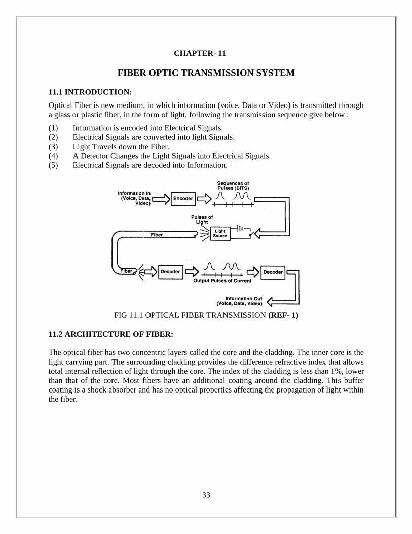
11.1 INTRODUCTION:
Optical Fiber is new medium, in which information (voice, Data or Video) is transmitted through
a glass or plastic fiber, in the form of light, following the transmission sequence give below :
(1) Information is encoded into Electrical Signals.
(2) Electrical Signals are converted into light Signals.
(3) Light Travels down the Fiber.
(4) A Detector Changes the Light Signals into Electrical Signals.
(5) Electrical Signals are decoded into Information.
FIG 11.1 OPTICAL FIBER TRANSMISSION (REF- 1)
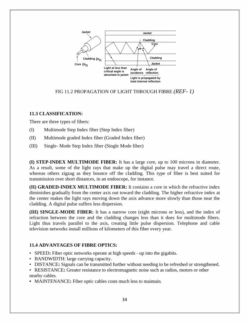
11.2 ARCHITECTURE OF FIBER:
The optical fiber has two concentric layers called the core and the cladding. The inner core is the
light carrying part. The surrounding cladding provides the difference refractive index that allows
total internal reflection of light through the core. The index of the cladding is less than 1%, lower
than that of the core. Most fibers have an additional coating around the cladding. This buffer
coating is a shock absorber and has no optical properties affecting the propagation of light within
the fiber.
34
FIG 11.2 PROPAGATION OF LIGHT THROUGH FIBRE (REF- 1)
11.3 CLASSIFICATION:
There are three types of fibers:
(I) Multimode Step Index fiber (Step Index fiber)
(II) Multimode graded Index fiber (Graded Index fiber)
(III) Single- Mode Step Index fiber (Single Mode fiber)
(I) STEP-INDEX MULTIMODE FIBER: It has a large core, up to 100 microns in diameter.
As a result, some of the light rays that make up the digital pulse may travel a direct route,
whereas others zigzag as they bounce off the cladding. This type of fiber is best suited for
transmission over short distances, in an endoscope, for instance.
(II) GRADED-INDEX MULTIMODE FIBER: It contains a core in which the refractive index
diminishes gradually from the center axis out toward the cladding. The higher refractive index at
the center makes the light rays moving down the axis advance more slowly than those near the
cladding. A digital pulse suffers less dispersion.
(III) SINGLE-MODE FIBER: It has a narrow core (eight microns or less), and the index of
refraction between the core and the cladding changes less than it does for multimode fibers.
Light thus travels parallel to the axis, creating little pulse dispersion. Telephone and cable
television networks install millions of kilometers of this fiber every year.
11.4 ADVANTAGES OF FIBRE OPTICS:
• SPEED: Fiber optic networks operate at high speeds - up into the gigabits.
• BANDWIDTH: large carrying capacity.
• DISTANCE: Signals can be transmitted further without needing to be refreshed or strengthened.
• RESISTANCE: Greater resistance to electromagnetic noise such as radios, motors or other
nearby cables.
• MAINTENANCE: Fiber optic cables costs much less to maintain.
Jacket
Cladding
Core
Cladding
Angle of
reflection
Angle of
incidence
Light at less than
critical angle is
absorbed in jacket
Jacket
Light is propagated by
total internal reflection
Jacket
Cladding
Core
(n2)
(n2)
Fig. Total Internal Reflection in an optical Fibre
35
CHAPTER- 12
Advanced Optical Networks: DWDM
(DENSE WAVELENGTH DIVISION MULTIPLEXING)
INTRODUCTION The revolution in high bandwidth applications and the explosive growth of the Internet,
however, have created capacity demands that exceed traditional TDM limits. To meet growing
demands for bandwidth, a technology called Dense Wavelength Division Multiplexing (DWDM) has
been developed that multiplies the capacity of a single fiber. DWDM systems being deployed today
can increase a single fiber’s capacity sixteen fold, to a throughput of 40 Gb/s. The emergence of
DWDM is one of the most recent and important phenomena in the development of fiber optic
transmission technology. Dense wavelength-division multiplexing (DWDM) revolutionized
transmission technology by increasing the capacity signal of embedded fiber.
One of the major issues in the networking industry today is tremendous demand for
more and more bandwidth. Before the introduction of optical networks, the reduced availability of
fibers became a big problem for the network providers. However, with the development of optical
networks and the use of Dense Wavelength Division Multiplexing (DWDM) technology, a new and
probably, a very crucial milestone is being reached in network evolution. The existing SONET/SDH
network architecture is best suited for voice traffic rather than today’s high-speed data traffic. To
upgrade the system to handle this kind of traffic is very expensive and hence the need for the
development of an intelligent all-optical network. Such a network will bring intelligence and
scalability to the optical domain by combining the intelligence and functional capability of
SONET/SDH, the tremendous bandwidth of DWDM and innovative networking software to spawn a
variety of optical transport, switching and management related products.In traditional optical fiber
networks, information is transmitted through optical fiber by a single light beam. In a wavelength
division multiplexing (WDM) network, the vast optical bandwidth of a fiber (approximately 30 THz
corresponding to the low-loss region in a single mode optical fiber) is carved up into wavelength
channels, each of which carries a data stream individually.
The multiple channels of information (each having a different carrier wavelength)
are transmitted simultaneously over a single fiber. The reason why this can be done is that optical
beams with different wavelengths propagate without interfering with one another. When the number
of wavelength channels is above 20 in a WDM system, it is generally referred to as Dense WDM or
DWDM.
DWDM technology can be applied to different areas in the telecommunication
networks, which includes the backbone networks, the residential access networks, and also the Local
Area Networks (LANs). Among these three areas, developments in the DWDM-based backbone
network are leading the way, followed by the DWDM-based LANs.
36
DEVELOPMENT OF DWDM TECHNOLOGY
Early WDM began in the late 1980s using the two widely spaced wavelengths in the 1310
nm and 1550 nm (or 850 nm and 1310 nm) regions, sometimes called wideband WDM. The early
1990s saw a second generation of WDM, sometimes called narrowband WDM, in which two to eight
channels were used. These channels interval of about 400 GHz in the 1550-nm window. By the mid-
1990s, dense WDM (DWDM) systems were
emerging with 16 to 40 channels and spacing from 100 to 200 GHz. By the late 1990s DWDM
systems had evolved to the point where they were capable of 64 to 160 parallel channels,
densely packed at 50 or even 25 GHz intervals. As fig. 1 shows, the progression of the technology
can be seen as an increase in the number of wavelengths accompanied by a decrease in the spacing of
the wavelengths. Along with increased density of wavelengths, systems also advanced in their
flexibility of configuration, through add-drop functions, and management capabilities.
37
CONCLUSION
Engineering student will have to serve in the public and private sector industries and workshop
based training and teaching in classroom has its own limitation. The lack of expo sure to real life,
material express and functioning of industrial organization is the measure hindrance in the
student employment.
In the open economy era of fast modernization and tough competition, technical industries
should procedure pass out as near to job function as possible.
Practical training is one of the major steps in this direction. I did my training from BSNL,
Bharatpur which is one of the best known communication service provider companies of India.
The training helps me in gaining in depth knowledge of the working of telephone exchange,
various technologies of BSNL –GSM, GPRS, WIMAX, Wi-Fi, MLLN and optical fiber
transmission.
In the end, I hereby conclude that I have successfully completed my industrial training on the
above topics.

38
BIBLIOGRAPHY AND REFERENCES
(I) BIBLIOGRAPHY:
1. Data Communication And Networking- Behrouz A. Foruzan
2. Wireless Communication and Networks-William Stallings
3. Computer Networking – Kurose & Ross
(II) REFERENCES:
4. www.bsnl.co.in
5. www.newbsnl.co.in