bifunctional nanocomposites: surface ... - uab barcelona · doctoral thesis doctoral studies in...
TRANSCRIPT
Bifunctional Nanocomposites:Surface Modification of Reactive Matrices
with Functional Metal Nanoparticlesby Intermatrix Synthesis Technique
Julio Bastos Arrieta Doctoral Thesis
Doctoral Studies in Chemistry
Supervisors:
Maria Muñoz Tapia &Dmitri Muraviev
Department of Chemistry
Faculty of Science
2014


Report submitted to aspire for the Doctor Degree
Julio Bastos Arrieta
Supervisors’ Approval;
Dra. Maria Muñoz Tapia Dr. Dmitri Muraviev
Bellaterra (Cerdanyola del Vallès), September 16th, 2014

Con, por y para mi familia

This work presented here has been possible thanks to the personal grand awarded from
Universitat A utònoma de B arcelona i n t he Personal Investigador en Formació
Fellowship P rogram. F inancial support was obt ained f rom the project Nuevo material
nanocomposite para el tratamiento combinado de aguas. (ACC1Ó, Departament
d’Innovació, Universitats i Empresa de la Generalitat de Catalunya, Spain) (VALTEC-
09-2-0056), de veloped u nder t he s upervision of Dr. D mitri M uraviev and D r. M aria
Muñoz Tapia executed within Grup de Tècniques de Separació and Grup de Sensors i
Biosensors from t he Departament de Química (Universitat A utònoma de B arcelona,
Barcelona, S pain) t o w hom I ha ve m ore t han gr atitude, s ince t hey bot h gui ded m e
through all these years.
I acknowledge t he s cientific a nd pe rsonal s upport of fered b y Dr. Yurii Gun’ko, D r.
Valerie Gerard and Ms. Raquel Serrano (Trinity College Dublin, Ireland) and Dr. Prof.
Larisa T sarkova a nd Ms. A nja S tenbock ( DWI Leibniz-Institut f ür Interaktive
Materialien Aachen, Germany) during the both three-month research stays which helped
me t o en hance m y s cientific ex pertise an d r esearch i ncluded i n t his P hD T hesis.

Table of Contents

Table of Contents
Table of Contents ............................................................................................................. II
Figure Index ...................................................................................................................... V
Table Index ....................................................................................................................... X
Acronym List .................................................................................................................. XI
Graphical Abstract ........................................................................................................ XIII
Summary ...................................................................................................................... XIV
Resum ............................................................................................................................ XV
Resumen ...................................................................................................................... XVI
1. Introduction ............................................................................................................... 1
1.1. General Introduction .......................................................................................... 1
1.2. Nanotechnology, Nanomaterials and Nanocomposites: historical background, properties and applications. .......................................................................................... 2
1.2.1. Nanoparticle Stabilization .......................................................................... 6
1.3. Stabilization of NPs with Polymers: Preparation and Synthesis of Polymer – Metal Nanocomposites by Intermatrix Synthesis Technique (IMS)............................. 7
1.3.1 The role of ion exchange in IMS .............................................................. 11
1.3.2 IMS of BFNCs with favourable distribution due to Donnan Exclusion Effect 15
1.3.3 IMS – precipitation stages for the preparation of BFNCs. ....................... 20
1.3.4 IMS – galvanic displacement stages for preparation of BFNCs. ............. 21
1.4. Characterization techniques for metal – polymer nanocomposites (PMNCs) . 22
1.4.1 Scanning electron microscopy(SEM) and Transmission electron Microscopy (TEM) .................................................................................................. 23
1.4.2 Scanning Transmission Microscopy ((S)-TEM) ...................................... 24
1.4.3 Laser Confocal Scanning Microscopy (LCSM) ....................................... 24
1.4.4 Spectroscopic Ellipsometry ...................................................................... 25
1.4.5 Brunauer – Emmet – Teller (BET) surface analysis: gas adsorption – desorption technique. .............................................................................................. 25
1.4.6 Inductively Coupled Plasma (ICP-MS) .................................................... 25
1.4.7 Thermogravimetric analysis (TGA) ......................................................... 26
1.5. Current and future applications of BFNCs prepared by IMS. ......................... 26
1.5.1 Heterogeneous Catalysis........................................................................... 28
1.5.2 Electrochemical Sensors: .......................................................................... 30
II

1.5.3 Bactericide Activity .................................................................................. 33
1.5.4 BFNCs for energy storage systems: ......................................................... 34
1.6. Concluding Remarks: ...................................................................................... 35
References ................................................................................................................... 36
2. Motivation, Aims and Publication Compendium .................................................... 45
2.1 Motivation, perspectives and research innovation ........................................... 45
2.2 General Aims ................................................................................................... 45
2.3 Specific Aims ................................................................................................... 46
2.4 Publication compendium ................................................................................. 46
3. Donnan Exclusion Effect Intermatrix Synthesis Technique: distribution and shape control technique for the environmentally friendly preparation of bifunctional nanocomposites. ............................................................................................................. 53
3.1 Preparation of CdS-QDs on cationic gel type polymeric matrix by DEEIMS-precipitation technique. ............................................................................................... 55
3.2 DEEIMS of Ag-FMNPs on gel-type cationic polymeric matrix with formaldehyde as neutral reducing agent. .................................................................... 57
3.3 DEEIMS of Au and Ag-FMNPs on gel-type anionic polymer using ascorbic acid (AA) and sodium borohydride (NaBH4) as ionic reducing agents. .................... 59
3.3.1 Symmetrical version of classical DEEIMS applied for anionic matrices. 59
3.3.2 DEEIMS of Au-FMNPs using anionic NPs-precursor. ............................... 61
3.4 DEEIMS of Ag-FMNPs on gel-type cationic polymer using AA and NaBH4 as reducing agents. .......................................................................................................... 64
3.4.1 Enhanced DEEIMS of Ag nano- and microstructures on cationic gel type polymers. ................................................................................................................. 68
3.4.2 Preparation of AgAu microstructures by DEEIMS-galvanic replacement technique. ................................................................................................................ 73
3.5 Concluding Remarks: ...................................................................................... 77
References: .................................................................................................................. 77
4. Evaluation of ion exchange properties and morphology changes due to IMS of Ag-FMNPs on gel –type polymeric matrices. ...................................................................... 84
4.1 Morphological changes on gel-type cationic polymer due to IMS of Ag-FMNPs: ....................................................................................................................... 84
4.2 Evaluation of ion exchange properties of cationic and anionic gel – type polymers before and after modification with Ag-FMNPs. ......................................... 92
4.3 Concluding Remarks ........................................................................................ 97
References ................................................................................................................... 97
III
5. Applications of Bifunctional Nanocomposites prepared by Intermatrix Synthesis Technique. .................................................................................................................... 102
5.1 Heterogeneous Catalysis: ............................................................................... 102
5.1.1 Synthesis and Characterization of Pd-MCNPs ....................................... 103
5.1.2 Evaluation of Catalytic Activity for Catalysis of Suzuki Cross Coupling Reaction(SCCR) .................................................................................................... 108
5.1.3 Concluding Remarks .............................................................................. 110
5.2 Further feasible approaches of IMS for novel reactive surfaces: .................. 110
5.2.1 Intermatrix Synthesis of FMNPs on multiwall CNTs (MWCNTs) ........ 111
5.2.2 Intermatrix Synthesis of CdS-QDs on SPEEK/PTFs (CdS-QDs@SPEEK/PTFs) ............................................................................................. 119
5.2.3 Intermatrix Synthesis of CdS-QDs on Nanodiamonds (CdS-QDs@NDs) 123
5.2.4 Concluding Remarks: ............................................................................. 125
References: ................................................................................................................ 125
6. Conclusions ........................................................................................................... 130
ANNEX 1 ..................................................................................................................... 137
ANNEX 2 ..................................................................................................................... 143
ANNEX 3 ..................................................................................................................... 148
ANNEX 4 ..................................................................................................................... 160
IV
Figure Index
Figure 1.1. examples of relevant discoveries and inventions dealing with development of materials technology. ................................................................................................... 1
Figure 1.2. Basic principles for the design of Nanomaterials ......................................... 2
Figure 1.3: Range of plasmonic resonance for gold nanoparticles in function of their morphology 25 ................................................................................................................... 4
Figure 1.4: Green principles scheme for the preparation of NMs. ................................... 5
Figure 1.5 Ostwald ripening mechanism for the uncontrollable growth of NPs in solution. ............................................................................................................................ 6
Figure 1.6 Different routes for the incorporation of FMNPs in a composite material a) In situ: using synthesis of FMNPs. b) Ex situ: FMNPs synthesis in solution and incorporation by impregnation to the matrix support ....................................................... 7
Figure 1.7 A) In read the number of publication per year introducing the term “nano” and in blue the publications per year introducing the term “Nanocomposite”. . B) Shows the trending topics of the overall publications related to “nano” in 2013. ....................... 8
Figure 1.8 FMNPs stabilized in polymeric matrix (A) by IMS that offers mechanical resistance(B) to reduce the risk of NMs release. .............................................................. 9
Figure 1.9 breakthrough profile scheme for ion exchange. ........................................... 13
Figure 1.10 different breakthrough profiles in function of polymer selectivity kinetics. Reversible process (black), non-favourable process (red dash curve) and favourable process (blue dash curve). .............................................................................................. 14
Figure 1.11: Scheme of ion exchange processes during stage 1 IMS in A) cationic exchanger, B) anionic exchanger and the final FMNPs favourable distribution on the surface of the BFNCs C) proved by cross section SEM images in which white zone show FMNPs layer. ........................................................................................................ 16
Figure 1.12: Increase of FMNPs layer thickness due to consecutive IMS cycles. ......... 17
Figure 1.13 Different FMNPs structures achievable by different IMS alternative routes: a) monometallic b,c) bi-metallic Core-Shell structure in function of the order of IMS stages and d) Alloy FMNP. ............................................................................................ 19
Figure 1.14: Confocal Laser microscopy of smooth gel –type cationic a) smooth surface and b) surface roughness increase due to IMS of Ag-FMNPs. ...................................... 19
Figure 1.15: A) Ag micro cube obtained by IMS on gel type cation exchanger and B) EDS spectra identifying the silver content in micro cube structure. .............................. 21
V
Figure 1.16: Galvanic displacement of Ag to Au to prepare a) AgAu micro cubes on gel type cationic exchange and b) EDS spectra identifying the presence of silver and gold with profile distribution (Au over Ag). .......................................................................... 22
Figure 1.17: Advantages of heterogeneous nanocatalysis. ............................................. 28
Figure 1.18: Scheme of feasible separation methods for BFNCs materials for catalytic applications. .................................................................................................................... 29
Figure 1.19: Scheme of the enhanced electronic transfer of modified electrodes with FMNPs. ........................................................................................................................... 32
Figure 1.20: Calibration curves of electrochemical detection of H2O2 concentration with Pt@Cu, Pt- and Cu-FMNP composite SPEEK membranes Experimentalconditions: potential: –250 mV; 0.1 M acetate buffer(Adapted from Muraviev et.al98) .................. 33
Figure 1.21: Bactericide activity of hybrid AgAu –cubic microstructures containing NCs ................................................................................................................................. 34
Figure 3.1: Schematic representation of the DEE during ion exchange showing repulsion, attachment and diffusion through DEE layer depending on the charge of species and layer. ............................................................................................................ 54
Figure 3.2: Schematic represtnatio of FMNPs distribution due to IMS A) Raw ion exchanger surface B) FMNPs with favourable distribution mianly on the ion exchanger surface because of DEE interaction with metal precursors and reducing agents and C) FMNPs distribution ........................................................................................................ 55
Figure 3.3: A) Cross section SEM image of CdS-QDs containing nanocomposite. B) EDS – LineScan Analaysis of cross section showing the distribution of CdS-QDs ..... 56
Figure 3.4: A) Cross section of Ag-FMNPs containing nanocomposite with B) Element Mapping and C) EDS -LineScan analysis showing the interior distribution of Ag-FMNPs due to IMS with formaldehyde as reducing agent ............................................ 58
Figure 3.5 Schematic representation of chemical structures AA and [AA]ox ................ 60
Figure 3.6: Ag-FMNPs distribution mainly on the surface on gel-type anionic exchanger due to IMS. A, B) Cross section and LineScan using NaBH4 as reducing agent. C,D) Cross section and EDS LineScan using AA as reducing agent. ..................................... 61
Figure 3.7: HR-SEM image and size distribution histogram of Au FMNPs on anionic gel – type polymer A, B) IMS using NaBH4 as reducing agent. C,D) IMS using AA as reducing agent. Non evidence of agglomeration is observed in neither case. ................ 63
Figure 3.8: Ag-FMNPs distribution mainly on surface on gel-type cation-exchanger due to IMS. A,B) Cross section and LineScan using NaBH4 as reducing agent C,D) Cross section and EDS LineScan using AA as reducing agent ................................................ 65
Figure 3.9: HR-SEM image and size distribution histogram of Au FMNPs on cationic gel – type polymer A, B) IMS using NaBH4 as reducing agent. C, D) IMS using AA as reducing agent. No agglomeration is observed in both cases. ........................................ 66
VI
Figure 3.10: HR-SEM images of surface morphology changes on cationic gel-type ion-exchanger due to IMS of IMS of Ag-FMNPs. Magnification of D>>C>>B>>A. ......... 67
Figure 3.11: HR-SEM images of Ag-FMNPs on gel-type cationic polymer showing appearance of micro-cubic structures. Magnification of B>>A. .................................... 67
Figure 3.12: Schematic representation of formation of Ag –cubic structures on surface of gel-type cationic polymer by DEEIMS. ..................................................................... 69
Figure 3.13: HR-SEM images of different stages of the formation of Ag-cubic structures on gel-type cationic polymer using 0.01M NaBH4 as reducing agent during DEEIMS:70
Figure 3.14: HR-SEM images showing favourable distribution and homogenous size of optimized IMS of Ag-cubic structures with 0.05M NaBH4 as reducing agent. Magnification C>>B>>A. .............................................................................................. 70
Figure 3.15: HR-SEM images of different stages of the formation of Ag-cubic structures on gel-type cationic polymer using AA as reducing agent during DEEIMS: ................ 71
Figure 3.16: HR-SEM images and size distribution histograms of Ag-cub structures synthesized by optimized IMS A, B) with NaBH4 as reducing agent. C, D) with AA as reducing agent. No agglomeration evidence is observed in neither case. ...................... 72
Figure 3.17: A) HR-SEM image and B) EDS-LineScan of Ag-cubic structure showing distribution profile for Ag. ............................................................................................. 72
Figure 3.18: Schematic representation of galvanic replacement of Ag to Au for DEEIMS of AgAu-cubic structures. ............................................................................... 74
Figure 3.19: HR-SEM images of Ag-cubic structures (A, B) and consequent evidence of hollowed AgAu structures due to galvanic replacement of Ag to Au (C, D). ............... 75
Figure 3.20: Schematic representation of consecutive stages of Kirkendall Effect during the galvanic effect of Ag (grey colour) to Au (gold colour) for the preparation of hollowed NPs. ................................................................................................................. 75
Figure 3.21: HR-SEM images (A, B, C) and EDS-LineScan (D) for AgAu-cubic structures synthesized by DEEIMS. ............................................................................... 76
Figure 4.1: (A) High resolution SEM image of NC bead cross section and (B, C) Line Scan EDS spectra showing distribution of Ag-FMNPs (red) in sulfonic gel type cation-exchange resin modified with Ag-FMNPs. .................................................................... 85
Figure 4.2: Schematic diagram of interaction of FMNPs synthesized inside polymer matrix (B) and SEM images of cationic gel type polymer surface before (A) and after (C) IMS of Ag-FMNPs ................................................................................................... 86
Figure 4.3: High-resolution SEM images of: a) NPs free granulated polymer. b, c, d, e, f): Ag-FMNPs containing polymer with clearly seen as worm-like structure of NC surface and nanopores. Magnification a = b < c < d< e < f ............................................ 87
VII
Figure 4.4: High–Resolution SEM images of Ag-FMNPs with an average diameter of 33±1nm on gel type polymer, show distribution of the FMNPs with non-evident agglomerates after surface modification Magnification of b>>>a. ................................ 89
Figure 4.5: SEM images of cross sections of Ag-FMNPs-gel-type sulfonic polymer PMNC granules at different times of metal loading stage and thicknesses (Δl) of final FMNPs layer (time of a<b). ............................................................................................ 90
Figure 4.6: Thickness of FMNPs layer versus metal loading time. ............................... 90
Figure 4.7: Breakthrough curves of displacement of Na+ with Ca2+ from FMNPs-free sulfonic cation-exchange resin and NCs obtained after different times of metal loading stage. Area marked by dotted lines corresponds to ion exchange capacity of resin and NC samples. .................................................................................................................... 94
Figure 4.8: Breakthrough curves of displacement of OH- with Cl- ions from FMNPs-free quaternary amine anion-exchange resin (grey) and NC (dark grey) obtained by DEEIMS technique with metal loading time of 1 minute. ............................................................. 95
Figure 5.1: SEM images of granule cross-sections and respective LineScan EDS spectra showing distribution of Pd-MNPs inside nanocomposites obtained by (A) classic and (B,C) novel version of IMS technique by using cation (A) and anion exchange resins (B,C) ............................................................................................................................. 106
Figure 5.2: SEM images of Purolite A520E resin (sample MNCP E in Table 5.1) before (A) and after (B and C) DEDIMS of Pd-PSMNCs. ..................................................... 107
Figure 5.3: TEM images (A, B) and size distribution histogram (C) of MCNP A (sample MNCP 3, see Table 5.1) ............................................................................................... 108
Figure 5.4: SCCR yield per catalytic run due to the application of the Pd-MCNPs .... 109
Figure 5.5: Lineal increase of SCCR yield as function of palladium content in Pd-PSMNCs containing nanocomposite. ........................................................................... 109
Figure 5.6: Schematic representation of catalytic performance of Pd-PSMNCs containing nanocomposite for SCCR. .......................................................................... 110
Figure 5.7: HR-TEM images of A) raw MWCNTs; B) Ag-; C) Au-; D) Cu-; E) Pd- and F) Pt-FMNPs@MWCNTs ............................................................................................ 113
Figure 5.8: HR-TEM images of A) raw MWCNTs; B) Pd-FMNPs@MWCNTs C) Pd-FMNPs@MWCNTs amplification and D) the corresponding EDS spectra from C. ... 114
Figure 5.9: A) HR-TEM raw MWCNT B) HR-(S)TEM CdS-QDs on MWCNTs after one IMS cycle. C) and d) HR-(S)TEM images of CdS-QDs on MWCNTs after two sequential IMS cycles. Magnification of D>>C. .......................................................... 115
Figure 5.10: A) (S)TEM image and B) size distribution histogram for CdS-QDs on MWCNTs with an average diameter of 2.3 ± 0.4nm. .................................................. 116
Figure 5.11: EDS spectra of A) MWNCTs Catalyst showing high Ni content. B) CdS-QDs showing the presence of Cd and S. ...................................................................... 116
VIII
Figure 5.12: Scheme of analytical procedure for determination of MWCNTs in water. A) addition of Cd(NO3)2 aqueous solution to blank and water sample under analysis, B) precipitation of CdS(s) and formation of CdS-QDs on MWCNTs surface, C) centrifugation and D) aliquot from liquid phases of blank and analyte is analysed on spectrophotometer for detection of MWCNTs due to presence of CdS-QDs. ............. 118
Figure 5.13: Dependence of intensity of fluorescence emission at wavelength of λ= 405nm on relative concentration of MWCNTs decorated with CdS-QDs. Zero point corresponds to emission of blank (see text). ................................................................ 119
Figure 5.14: Schematic representation of SC of SPEEK over silicon wafers: dropping of SPEEK (A) followed by spin – up of SPEEK (B). Actual picture of SPEEK dissolved polymer in DMF interacting with Silicon wafer as product of spin-off stage (C, D). PTsF formation after evaporation stage (E, F). ............................................................ 121
Figure 5.15: A) Schematic representation of IMS of CdS-QDs on SPEEK PTFs. B) (S)TEM picture of CdS-QDs with their corresponding EDS on C. D) HR-TEM image and size distribution histogram of QDs (E). ................................................................. 122
Figure 5.16: HR-TEM images of NDs (A,B magnification B>>>A) and raw NDs size distribution histogram(C). ............................................................................................ 123
Figure 5.17: A) Schematic representation of IMS CdS-QDS on NDs. B) HR-TEM image of raw NDs and EDS spectra on D. C) (S)TEM image of CdS-QDs modified NDs and corresponding EDS spectra on E. .................................................................. 124
IX
Table Index
Table 1.1: Atoms exposed in Au-NPs surface as function of NP diameter.14................. 3
Table 1.2: Reactive matrices used for IMS of FMNPs................................................... 18
Table 1.3: main characterization techniques commonly used for BFNCs. .................... 23
Table 4.1: Increase of pore diameters in Ag-MNPs-containing Purolite C100E resin samples ........................................................................................................................... 87
Table 4.2: Thickness values of Ag-FMNPs layer at low metal loading times determined from cross section measurements ................................................................................... 91
Table 5.1: Metal content in Pd-PSMNCs nanocomposites synthesized by applying different metal loading-reduction cycles. ..................................................................... 105
Table 5.2: TGA analysis of FMNPs@ MWCNTs/expoxy composites ........................ 114
X
Acronym List
Acronym Meaning
AA Ascorbic Acid BET Brunauer – Emmet – Teller BFNCs Bifunctional Nanocomposites CNTs Carbon Nanotubes DEE Donnan Exclussion Effect
DEEIMS Intermatrix Synthesis coupled with Donnan Exclussion Effect
DMF Dimethylformamide EDS Energy dispersive X-Ray Spectroscopy FMNPs Functional Metal Nanoparticles FNMs Functional Nanomaterials ICP Inductively Coupled Plasma IEC Ion Exchange Capacity IMS Intermatrix Synthesis LCSM Laser Confocal Scanning Microscopy MNPs Metal Nanoparticles MWCNTs Multiwall Carbon Nanotubes NCs Nanocomposites NDs Nanodiamonds NMs Nanomaterials NPs Nanoparticles PMNCs Polymer Metal Nanocomposites PTFs Polymeric Thin Films QDs Quantum Dots SEM Scanning Electron Microscopy SPEEK Sulfonated Poly(etherether)ketone STEM Scanning Transmission Electron Microscopy TEM Transmission Electron Microscopy TGA Thermogravimetric Analysis
XI

“Ama no lo que eres; sino aquello en lo que te puedes llegar a convertir”
-DQ-

Summary
Graphical Abstract
XIII
Summary
In this Doctoral Thesis, the Intermatrix Synthesis (IMS) technique has been described as a f easible me thodology for th e mo dification o f reactive m atrices w ith Nanoparticles (NPs), w hich i s ba sed o n t he i on e xchange pr operties of t he N Ps s upporting s urface, such as ion exchange resins and the innovation of the application of IMS on pol ymeric nanofilms, carbon nanotubes (CNTs) and nanodiamonds(NDs).
The ef fects o f n anostructured materials on t he e nvironment are one of t he m ost important issues of technology in recent years. Given their high level of development, production, di ssemination a nd a pplication, t he m ain c oncerns associated w ith nanomaterials ( NMs) i nclude: a ) t he hi gh r eactivity a nd t oxicity of m any NMs compared t o t heir m acroscopic a nalogues, b) t he l ack of a ppropriate a nalytical techniques f or t heir de termination in environment a nd c) t he ab sence o f ef fective legislation to r egularize th e convenient levels of va rious N Ms i n s oil, w ater a nd air. Therefore, i t is a m ust t o e nsure the s ecurity a nd s tability of N Ms t hrough i ts incorporation into the Bifunctional Nanocomposites (BFNCs)
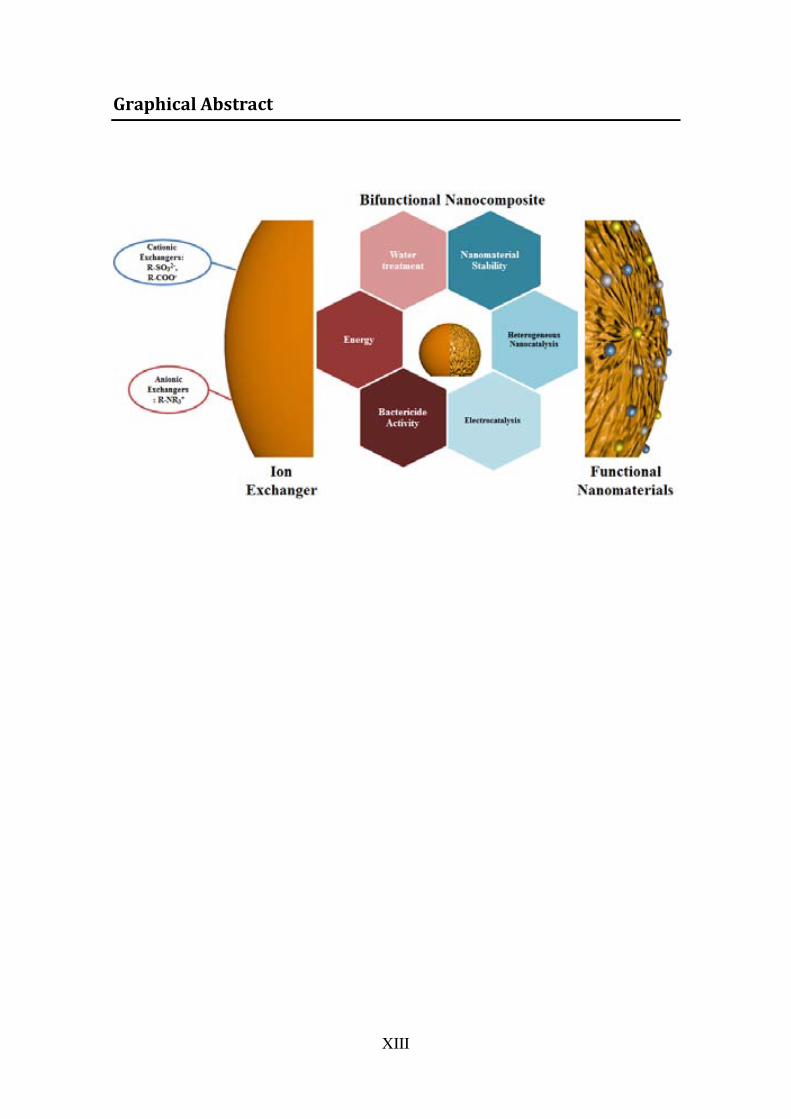
The bifunctionality of BFNCs is determined by the specific properties of the matrix in which the metal NPs (MNPs) are synthesized (for example by ion exchange polymers) and b y t he r espective pr operties of t he M NPs ( magnetism, b actericidal, nanocatlizadores). S urface m odification of reactive matrices w ith M NPs is c onducted through t he IMS c oupled t o D onnan e xclusion effect ( DEE). T hus, t he added value BFNCs prepared are characterized, their p roperties are evaluated and s tability and the favourable distribution of the MNPs mainly on the surface of BFNCs is verified.
The IMS includes different possibilities for the preparation of MNPs on BFNCs. In the first s tage i on e xchange i s pe rformed on t he m atrix t o a ttach t he NPs p recursors. Subsequently, the IMS includes: a) Reduction of ions by using a reducing agent such as NaBH4 or b) precipitation of NMs as quantum dots (QDs) or metal oxides by adding the respective counterion. Whichever route is followed, the ion exchange functional groups of the matrix are regenerated; so IMS cycles can be repeated to increase the thickness of the MNPs or to produce bimetallic core-shell type MNPs. An extended version of the IMS is presented as using galvanic replacement for the preparation of Au- MNPs and AgAu-MNPs in cationic matrices using MNPs in itially s ynthesized as n ano-templates for crystallization of new mono or bimetallic MNPs.
An important advantage provided by the IMS technique is i ts versatility, allowing the synthesis of BFNCs with t he desired p roperties for d ifferent applications: bactericidal activity, magnetism, electrochemistry and heterogeneous catalysis, among others.
XIV
Resum
En aquesta Tesi Doctoral s 'ha desenvolupat l a t ècnica de S íntesi intermatricial ( IMS), com a una m etodologia factible p er l a m odificació d e m atrius r eactives amb nanopartícules (NPs) basada en les propietats d 'intercanvi iònic de la superfície que es vol m odificar; c om a ra: r esines i ntercanviadores i òniques i l a i nnovació e n l a modificació d e n anofilms p olimèrics f uncionalitzats, na notubs de c arboni ( CNTs) i nanodiamantes (NDs).
L’efecte d els m aterials n anoestructutrats s obre el m edi am bient és u n d els t emes m és importants a l a t ecnologia en el s d arrers anys. A cau sa d el s eu al t g rau d e desenvolupament, pr oducció, d ifusió i ap licació, l es m ajors p reocupacions as sociades als Nanomaterials (NMs) inclouen: a) l'elevada reactivitat i to xicitat de molts NMs en comparació d els s eus a nàlegs m acroscòpics, b ) l 'absència d e t ècniques an alítiques òptimes per a l a seva determinació en e l medi ambient i c ) l'absència d 'una legislació efectiva que regularitzi el s n ivells permesos de diversos NMs en sòl, aigua i ai re. Per això és primordial la seguretat i estabilitat dels NMs a través de la seva incorporació en els Nanocomposites bifuncionals (BFNCs)
La bifuncionalitat dels BFNCs és determinada per les propietats pròpies de la matriu en la q ual le s N Ps me tàl·liques ( MNPs) s ón s intetitzades ( per e xemple p olímers d'intercanvi iònic) i p er les p ropietats respectives de les MNPs (magnetisme, activitat bactericida, nanocatlizadores). La modificació superficial de les matrius reactives amb MNPs es p orta a t erme a t ravés d e l a IMS a coblada a l 'Efecte d 'exclusió d e D onnan (DEE). D'aquesta manera, els BFNCs preparats amb valor afegit són caracteritzats, les seves propietats són avaluades i es comprova l'estabilitat i la distribució favorable de les MNPs principalment en la superfície dels BFNCs.
La IMS i nclou di ferents pos sibilitats pe r a l a pr eparació de M NPs i BFNCs. E n una primera etapa es realitza un intercanvi iònic sobre la matriu per fixar els precursors de les NPs. Posteriorment la IMS pot incloure: a) Reducció dels ions a l 'utilitzar un a gent reductor co m N aBH4 o b) pr ecipitació de N Ms c om qua ntum dot s ( QDs) o òxi ds metàl·lics a l'afegir el contraió respectiu. Sigui quina sigui la ruta que s'empri, els grups funcionals d'intercanvi iònic propis de la matriu són regenerats; de manera que els cicles de IMS poden repetir-se per augmentar e l gruix de les MNPs o bé per produir MNPs bimetàl·liques tipus core-shell. Una versió estesa de la IMS és presentada a l'utilitzar el desplaçament g alvànic co m a p recursor p er A u- MNPs i Ag Au-MNPs a ma trius catiòniques, u tilitzant MNPs s intetitzades in icialment c om n anoplantilles p er a la cristal·lització de les noves MNPs mono- o bi- metàl·liques.
Un av antatge m olt i mportant q ue ap orta l a t ècnica IMS és l a s eva g ran v ersatilitat, possibilitant la s íntesi d e BFNCs amb le s p ropietats d esitjades p er a le s d iferents aplicacions: a ctivitat b actericida, m agnetisme, catàlisi h eterogènia i el ectroquímica, entre d'altres.
XV
Resumen
En esta Tesis D octoral s e h a d esarrollado l a t écnica d e S íntesis Intermatricial ( IMS), como una m etodología f actible p ara l a modificación de m atrices r eactivas con Nanoparticulas(NPs) basada en l as propiedades de intercambio iónico de la superficie que s e d esea m odificar; t ales co mo: co mo r esinas i ntercambiadoras iónicas y l a innovación en la modificación de nanofilms poliméricos funcionalizados, nanotubos de carbono (CNTs) y nanodiamantes (NDs).
El ef ecto d e l os m ateriales n anoestructurados s obre e l m edio a mbiente e s uno de l os temas m ás i mportantes de l a t ecnología e n l os últimos a ños. D ado s u alto gr ado de desarrollo, producción, di fusión y aplicación, l as mayores preocupaciones asociadas a los Nanomateriales (NMs) incluyen: a) l a el evada reactividad y toxicidad de muchos NMs e n c omparación c on s us a nálogos m acroscópicos, b) l a a usencia de t écnicas analíticas adecuadas para su determinación en el medio ambiente y c) la ausencia de una legislación efectiva que regularice los niveles permitidos de varios NMs en suelo, agua y aire. P or e llo e s pr imordial l a s eguridad y e stabilidad de l os N Ms a t ravés de s u incorporación en los Nanocomposites Bifuncionales (BFNCs)
La bi funcionalidad de l os BFNCs es de terminada por l as pr opiedades propias de l a matriz en la que las NPs metálicas (MNPs) son sintetizadas (por ejemplo polímeros de intercambio i ónicos) y por l as pr opiedades r espectivas de l as M NPs (magnetismo, actividad ba ctericida, na nocatlizadores). La m odificación s uperficial d e las m atrices reactivas co n l as M NPs s e l leva a c abo a t ravés d e l a IMS aco plada al E fecto d e Exclusión de Donnan (DEE). De esta manera, los BFNCs preparados con valor añadido son c aracterizados, s us propiedades son ev aluadas y s e comprueba l a es tabilidad y l a distribución favorable de las MNPs principalmente en la superficie de los BFNCs.
La IMS i ncluye d iferentes posibilidades para l a preparación d e MNPs en BFNCs. En una p rimera et apa s e r ealiza u n i ntercambio i ónico s obre l a m atriz p ara f ijar l os precursores de las NPs. Posteriormente la IMS puede incluir: a) Reducción de los iones al u tilizar un agente reductor como NaBH4 o b) precipitación de NMs como quantum dots (QDs) u óxidos metálicos al agregar el contraión respectivo. S ea cual sea la ruta que s e s iga, l os gr upos f uncionales de i ntercambio i ónico pr opios de l a m atriz s on regenerados; por lo que los ciclos de IMS pueden repetirse para aumentar el grosor de las MNPs o bien para producir MNPs bimetálicas tipo core-shell. Una versión extendida de l a IMS es p resentada al u tilizar el d esplazamiento g alvánico co mo p recursor p ara Au- MNPs y Ag Au-MNPs e n ma trices c atiónicas, u tilizando M NPs s intetizadas inicialmente como na noplantillas pa ra l a c ristalización de l as nue vas M NPs m ono o bimetálicas.
Una v entaja m uy i mportante q ue ap orta l a t écnica IMS es s u g ran v ersatilidad, posibilitando la s íntesis d e BFNCs con l as p ropiedades d eseadas p ara l as d iferentes aplicaciones: actividad bactericida, magnetismo, catálisis heterogénea y electroquímica, entre otras.
XVI

“There is nothing to be scared of, just everything to be explained”
-Marie Curie-

Introduction
1. Introduction
1.1. General Introduction
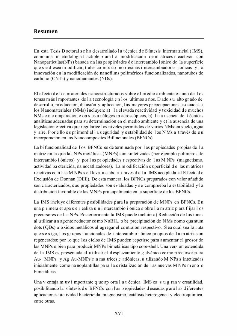
Everyday humans interact with a great amount of different materials and with
the imminent need to control matter. Since the very beginning of their existence,
humans have design materials to change and take advantage of the surrounding
elements to improve their life quality. Figure 1.1 presents some relevant
inventions through the history of humanity.
Figure 1.1. Examples of relevant discoveries and inventions dealing with development of materials technology.
Life in the twenty-first century is ever dependent on an unlimited variety of
advanced materials. The term material may be broadly defined as any solid-state
component or device that may be used to address a current or future societal
need. For instance, simple building materials such as nails, wood, coatings, etc.
address our need of shelter.
Material Science is focused on the understanding of the order of atoms, ions or
molecules, that all joint turn out as a material1. Bulk materials usually present
different physical and chemical properties different from their nano-sized
components.
The broad field of study of Material Science includes structures/properties of
existing materials, synthesizing and characterizing novel, efficient and greener
1
materials. Furthermore, in perspective, material science pursues to estimate
feasible properties of materials that has not yet been realized or invented.2–7
The design of materials depends on the current necessities of the society, the
availability of resources and the investment required for an appropriate scale up
production.
1.2. Nanotechnology, Nanomaterials and Nanocomposites: historical background, properties and applications.
The main aim of material scientist is to overcome with new efficient and low
cost methodologies for the preparation of novel materials. Taking that into
account, the incorporation of Nanomaterials (NMs) into bulk components has
become a priority. 8–11
NMs represent an alternative to conventional materials and have repercussion
in fields like electronics, biochemical sensors, catalysis and energy. The
nanoscale particles (from 1-10 0nm) increase the exposed surface area of the
active component of the nanoparticles (NPs), enhancing properties as charge
transfer and catalytic activity.12,13 Table 1.1 presents the data related to the ratio
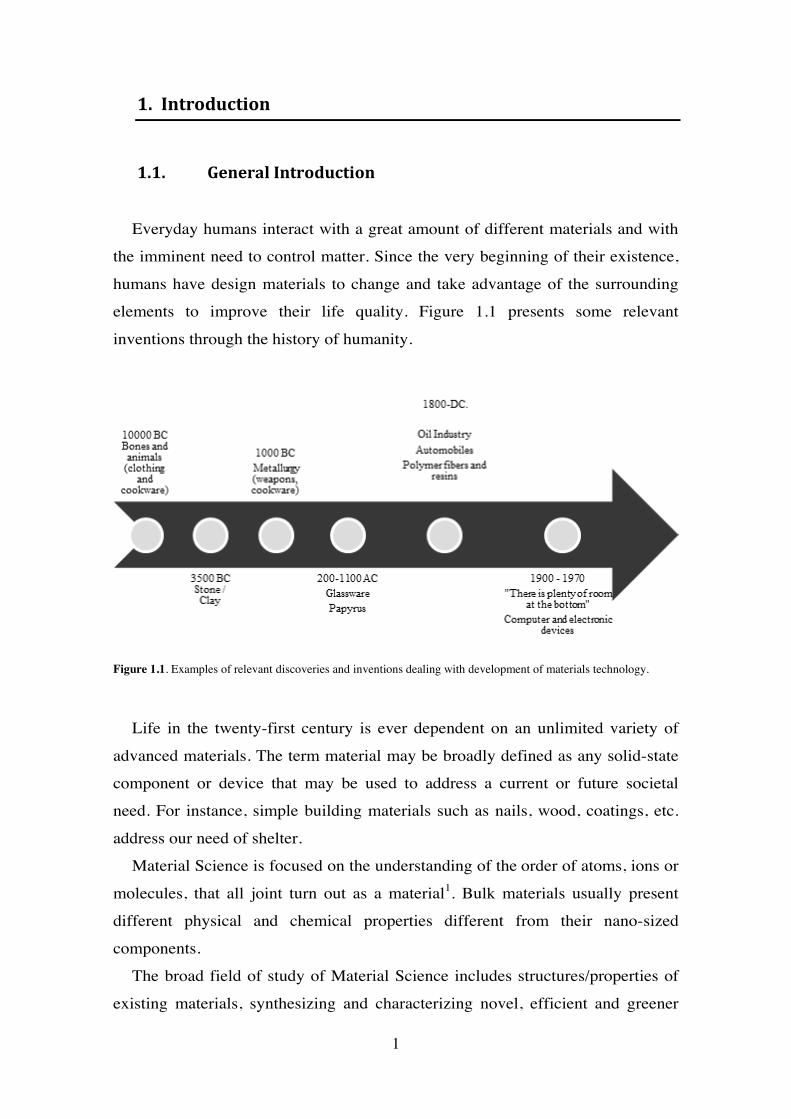
Figure 1.2. Basic principles for the design of Nanomaterials
2
Target Application
State of the art
Properties: Desired or to
enhance
2. Basic principles for the design of
enhance
Development Methodlogy
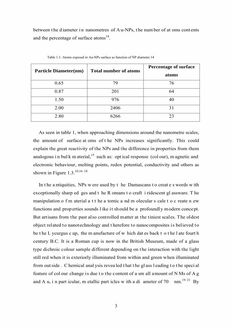
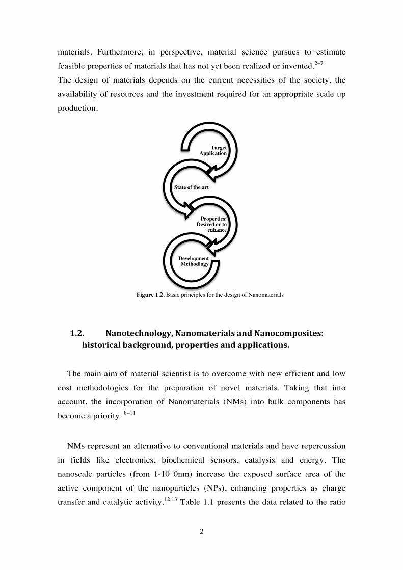
between t he d iameter i n nanometres of A u-NPs, t he num ber of at oms cont ents
and the percentage of surface atoms14.
Table 1.1: Atoms exposed in Au-NPs surface as function of NP diameter.14
Particle Diameter(nm) Total number of atoms Percentage of surface
atoms
0.65 79 76
0.87 201 64
1.50 976 40
2.00 2406 31
2.80 6266 23
As seen in table 1, when approaching dimensions around the nanometre scales,
the amount of surface at oms of t he NPs increases significantly. This could
explain the great reactivity of the NPs and the difference in properties from them
analogous i n bul k m aterial,15 such as: opt ical response (col our), m agnetic and
electronic behaviour, melting points, redox potential, conductivity and others as
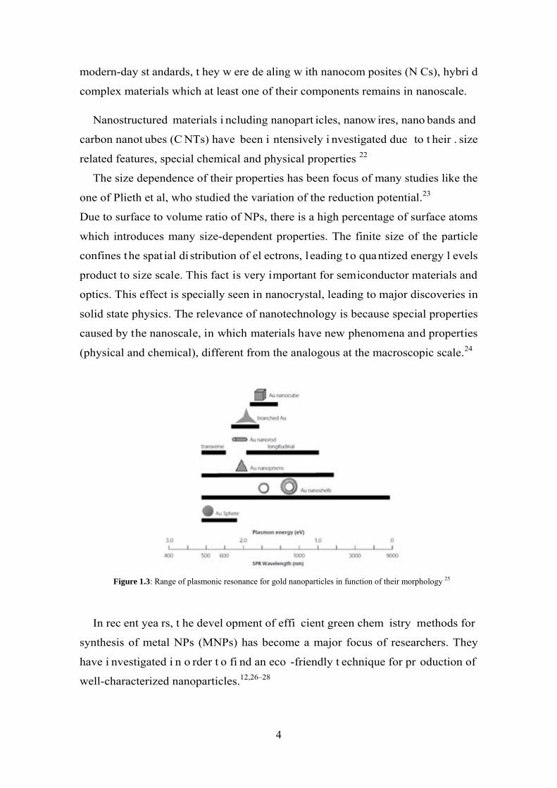
shown in Figure 1.3.10,16–18
In t he a ntiquities, NPs w ere used by t he Damascans t o creat e s words w ith
exceptionally sharp ed ges and t he R omans t o craft i ridescent gl assware. T he
manipulation o f m aterial a t t he a tomic a nd m olecular s cale t o c reate n ew
functions and properties sounds l ike i t should be a profoundly modern concept.
But artisans from the past also controlled matter at the tiniest scales. The oldest
object related to nanotechnology and t herefore to nanocomposites is believed to
be t he L ycurgus c up, the m anufacture of w hich dat es back t o t he l ate fourt h
century B.C. It is a Roman cup is now in the British Museum, made of a glass
type dichroic colour sample different depending on t he interaction with the light
still red when it is exteriorly illuminated from within and green when illuminated
from out side . C hemical anal ysis revea led t hat t he gl ass l eading t o t he speci al
feature of col our change is due t o the content of a sm all amount of N Ms of A g
and A u, i n part icular, m etallic part icles w ith a di ameter of 70 nm.19–21 By
3
modern-day st andards, t hey w ere de aling w ith nanocom posites (N Cs), hybri d
complex materials which at least one of their components remains in nanoscale.
Nanostructured materials i ncluding nanopart icles, nanow ires, nano bands and
carbon nanot ubes (C NTs) have been i ntensively i nvestigated due to t heir . size
related features, special chemical and physical properties 22
The size dependence of their properties has been focus of many studies like the
one of Plieth et al, who studied the variation of the reduction potential.23
Due to surface to volume ratio of NPs, there is a high percentage of surface atoms
which introduces many size-dependent properties. The finite size of the particle
confines the spat ial di stribution of el ectrons, l eading to quantized energy l evels
product to size scale. This fact is very important for semiconductor materials and
optics. This effect is specially seen in nanocrystal, leading to major discoveries in
solid state physics. The relevance of nanotechnology is because special properties
caused by the nanoscale, in which materials have new phenomena and properties
(physical and chemical), different from the analogous at the macroscopic scale.24
Figure 1.3: Range of plasmonic resonance for gold nanoparticles in function of their morphology 25
In rec ent yea rs, t he devel opment of effi cient green chem istry methods for
synthesis of metal NPs (MNPs) has become a major focus of researchers. They
have i nvestigated i n o rder t o fi nd an eco -friendly t echnique for pr oduction of
well-characterized nanoparticles.12,26–28
4
The use of engineered NPs as a consequence of the emerging field of materials
science a nd m ainly of nanot echnology i s a conc ern of envi ronmental sci entists
worldwide. However, a few studies have al ready demonstrated the toxic effects
of NPs on various organisms. In despite of the extensive publications and studies
involving Nanotechnology, it is still in discovery phase in which novel materials
are first synthesized in small scale in order to identify new properties and further
applications29–31.
Some aspects can be taken into account referring to NPs release and effects:
1. NPs effe cts are scale depe ndent and not the sam e in l arger scale or
agglomerates. T his m eans t hat ef fects m ay be qui et di fferent t o adopt
specific and more appropriate regulations.
2. These differences are based on size, surface chemistry and other specific
interactions dependi ng on t he sc ale. T hus, t he sa me m aterial may hav e
different regulations through the different sizes presented.
3. Effects must be conclusive to those products which commercialization is
imminent. So, t he N Ps present ed i n t he fi nal produc t m ay be t he ones,
which the studies should focus on.
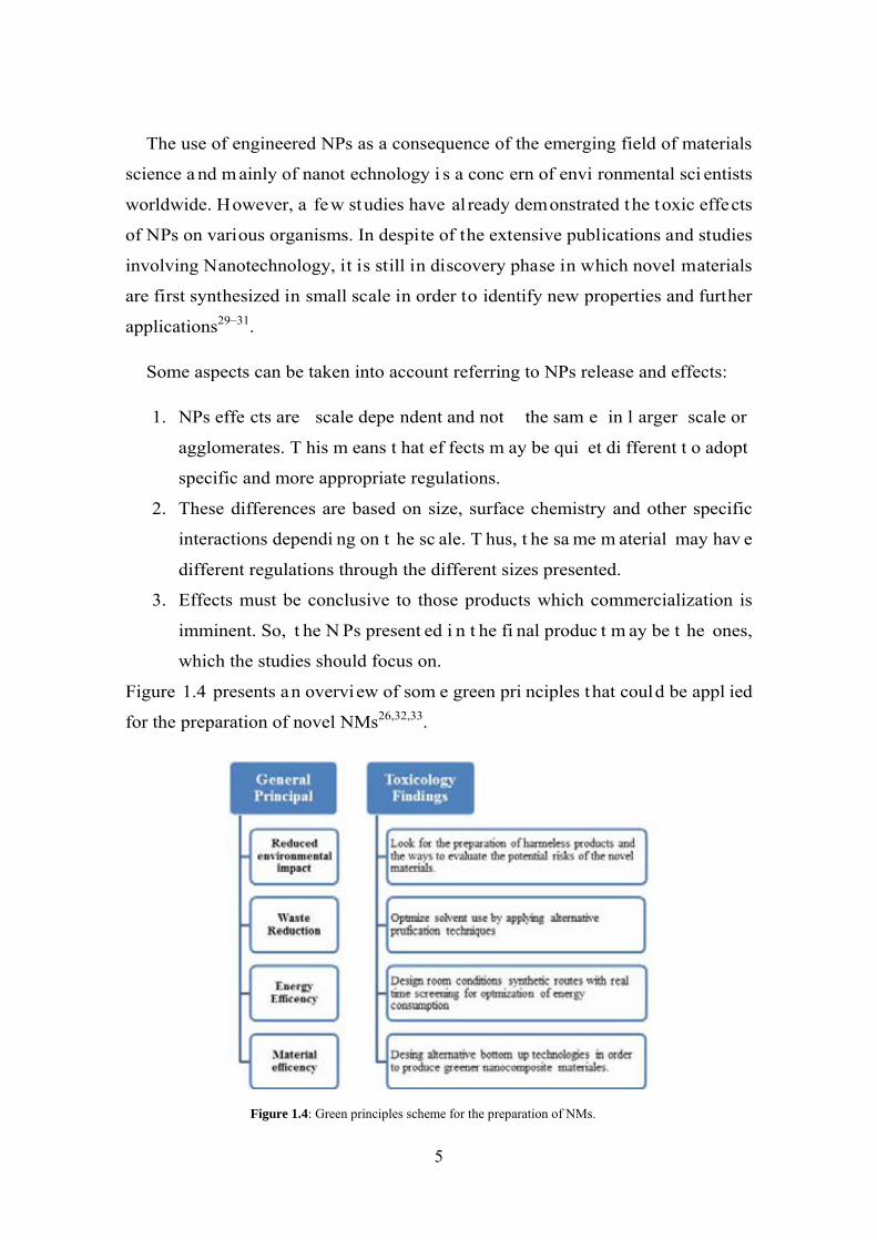
Figure 1.4 presents an overview of som e green pri nciples that could be appl ied
for the preparation of novel NMs26,32,33.
Figure 1.4: Green principles scheme for the preparation of NMs.
5
The environmental safety of nanocomposites, which consist of or contain
nanoscale components, is one of the most important emerging topics of the
Material Science and Nanotechnology fields. The main concerns dealing with the
rapid development and commercialization of various nanomaterials are associated
with:34–36
1. the approved higher toxicity of many NMs in comparison with their larger
counterparts.
2. the absence of the adequate analytical techniques for detection of NMs in
the environment
3. the absence of the legislation normative for permitted levels of various
NMs in water and air.
1.2.1. Nanoparticle Stabilization
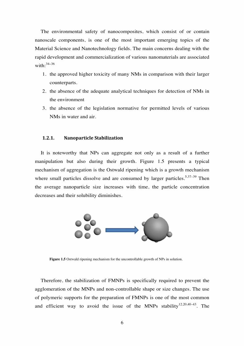
It is noteworthy that NPs can aggregate not only as a result of a further
manipulation but also during their growth. Figure 1.5 presents a typical
mechanism of aggregation is the Ostwald ripening which is a growth mechanism
where small particles dissolve and are consumed by larger particles.5,37–39 Then
the average nanoparticle size increases with time, the particle concentration
decreases and their solubility diminishes.
Therefore, the stabilization of FMNPs is specifically required to prevent the
agglomeration of the MNPs and non-controllable shape or size changes. The use
of polymeric supports for the preparation of FMNPs is one of the most common
and efficient way to avoid the issue of the MNPs stability12,20,40–43. The
Figure 1.5 Ostwald ripening mechanism for the uncontrollable growth of NPs in solution.
6
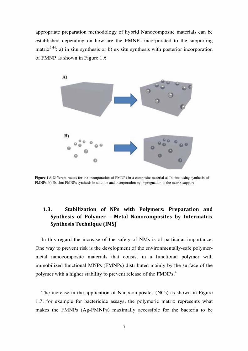
appropriate preparation methodology of hybrid Nanocomposite materials can be
established depending on how are the FMNPs incorporated to the supporting
matrix5,44: a) in situ synthesis or b) ex situ synthesis with posterior incorporation
of FMNP as shown in Figure 1.6
1.3. Stabilization of NPs with Polymers: Preparation and Synthesis of Polymer – Metal Nanocomposites by Intermatrix Synthesis Technique (IMS)
In this regard the increase of the safety of NMs is of particular importance.
One way to prevent risk is the development of the environmentally-safe polymer-
metal nanocomposite materials that consist in a functional polymer with
immobilized functional MNPs (FMNPs) distributed mainly by the surface of the
polymer with a higher stability to prevent release of the FMNPs.45
The increase in the application of Nanocomposites (NCs) as shown in Figure
1.7; for example for bactericide assays, the polymeric matrix represents what
makes the FMNPs (Ag-FMNPs) maximally accessible for the bacteria to be
Figure 1.6 Different routes for the incorporation of FMNPs in a composite material a) In situ: using synthesis of FMNPs. b) Ex situ: FMNPs synthesis in solution and incorporation by impregnation to the matrix support
7

eliminated. Another possibility of FMNPs synthesis is the Core-shell structure,
which contains a superparamagnetic core coated with the functional metal shell,
which provides, for example, the maximal bactericide activity51,52. The MNPs are
strongly captured in‐ side the polymer matrix that prevents their escape into the
medium under treatment. The superparamagnetic nature of FMNPs provides an
additional level of the material safety as FMNPs leached from the polymer matrix
can be easily captured by the magnetic traps to completely prevent any post-
contamination of the treated medium.
MNPs can be obtained by various synthetic routes5, such as electrochemical
methods, decomposition of organometallic precursors, reduction of metal salts in
the presence of suitable (monomeric or polymeric) stabilizers, or vapour
deposition methods. Sometimes, the presence of stabilizers is required to prevent
the agglomeration of nanoclusters by providing a steric or electrostatic barrier
between particles and, in addition, the stabilizers play a crucial role in controlling
both the size and shape of nanoparticles.53–55
FMNPs synthesized by in situ approaches; as IMS; exhibit long time stability
against aggregation and oxidation. In addition, another advantage offered by IMS
is the most favourable distribution of the FMNPs on the surface of the support. In
the ex-situ synthesis approach, MNPS are dispersed after their synthesis in a solid
or liquid medium by using different methodologies. .The stabilization is limited
by the re-aggregation of the MNPs along the time by the Oswald ripening
mechanism. Moreover; the final distribution of the MNPs in the support is not
0
20000
40000
60000
80000
100000
120000
140000
160000
2005 2006 2007 2008 2009 2010 2011 2012 2013
NU
MBE
R O
F PU
BLIC
ATI
ON
S
YEAR
Figure 1.7 A) In read the number of publication per year introducing the term “nano” and in blue the publications per year introducing the term “Nanocomposite”. . B) Shows the trending topics of the overall publications related to “nano” in 2013.
A B
8
entirely controlled and homogenous. In terms of feasible applications such as
catalysis, the presence of the FMNPs in a more accessible location to interact
with the reagents is an important fact to consider.42,45,46,51,56
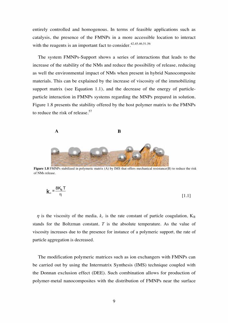
The system FMNPs-Support shows a series of interactions that leads to the
increase of the stability of the NMs and reduce the possibility of release, reducing
as well the environmental impact of NMs when present in hybrid Nanocomposite
materials. This can be explained by the increase of viscosity of the immobilizing
support matrix (see Equation 1.1), and the decrease of the energy of particle-
particle interaction in FMNPs systems regarding the MNPs prepared in solution.
Figure 1.8 presents the stability offered by the host polymer matrix to the FMNPs
to reduce the risk of release.57
ηB
c
8 K T=k[1.1]
η is the viscosity of the media, kc is the rate constant of particle coagulation, KB
stands for the Boltzman constant, T is the absolute temperature. As the value of
viscosity increases due to the presence for instance of a polymeric support, the rate of
particle aggregation is decreased.
The modification polymeric matrices such as ion exchangers with FMNPs can
be carried out by using the Intermatrix Synthesis (IMS) technique coupled with
the Donnan exclusion effect (DEE). Such combination allows for production of
polymer-metal nanocomposites with the distribution of FMNPs near the surface
Figure 1.8 FMNPs stabilized in polymeric matrix (A) by IMS that offers mechanical resistance(B) to reduce the risk of NMs release.
A B
9
of t he pol ymer what appe ars t o be t he m ost favourabl e i n t heir pract ical
applications.45–50
The fi rst c ommunication about IM S of FM NPs i n i on exc hange polymeric
materials dat es back to 1949, i n which Mills and Dickinson descri bed t he
preparation of a w eakly basi c a nion exchan ge resi n cont aining C opper M etal
Nanoparticles (C u-MNPs or “col loidal copp er”) and t he use of t his pol ymer-
metal nanocomposite to remove oxygen from water based on its interaction with
Cu-MNPs.58 Since then, many studies of the modification of ion exchange resins
with MNPs (mainly Cu-MNPs) resulted in the development of a new class of bi-
functional i on excha nge m aterials com bining bot h t he i on ex change properties
determined by t he pre sence of func tional g roups i n t he m atrix, and t he redox
properties due t o the presence of “col loidal metal” or MNPs in the matrix. They
are also known as redoxites and el ectron exchangers.59 Redoxites have found
wide application in the complex water treatment processes at power stations for
the rem oval of hardne ss i ons by i on exchan ge a nd di ssolved oxyg en by red ox
reactions w ith M NPs. H owever, essent ially n o i nformation about t he si zes and
the structures of MNPs in redoxite matrices and the features of t heir distribution
inside polymers can be found in the literature
As described before, IMS technique is an efficient and simple methodology for
the “in-situ” preparation of metal-polymer bi functional nanocomposites
(BFNCs). The general principles of IMS apply to all types of matrices (polymeric
or not) with ion exchange functionality and for different types of FMNPs.
The main requirements for an i on exchange matrix to be used as a su pport for
the IMS technique include:42,45
- The matrix must be chemically compatible with the FMNPs surface.
- It bears a charge due to t he presence of w ell-dissociated funct ional i on
exchange groups. This requires a preconditioning acid –base and NaCl
treatment of t he supp orting m atrix before I MS t echnique t hat us ually
results i n t he N a+-form for cat ionic excha ngers and t he C l--form for
anionic
- The functional groups act as nanoreactors.
10

- Appropriate di stances bet ween t he funct ional groups, i n order t o avoi d
agglomeration of FMNPs due to steric effects on the surface.
- Sufficient fl exibility of t he pol ymer chai n segm ents t o fa cilitate
movements of ionic carriers.
- Appropriate swelling ratio of the matrix.
- Adequate hydrophi licity: as IM S i s an envi ronmentally fri endly
methodology that is carried out in aqueous media.
Regarding t hese po ints, the m atrix act s as n anoreactors for t he F MNPs and
provide a confi ned medium for t he synt hesis cont rolling part icle si ze and
distribution. Moreover stabilizes and i solates t he generat ed FM NPs, prevent ing
their aggregation
1.3.1 The role of ion exchange in IMS
The Ion exchange functional groups of a matrix can immobilize metal ions and
metal ion complexes can be considered as the key points for IMS because they
are hom ogeneously d istributed i n t he i on excha nge m atrix an d be have as
combinations of si ngle i solated nanore actors ge nerating h omogeneous
nanocomposites.60,61 Ion Exchange polymeric matrices can be cl assified in four
main groups:35
• Cation exchangers (with anionic functionalities)
a) strong acid exchangers (e.g., containing sulfonic acid groups)
b) weak acid exchangers (e.g., containing carboxylic acid groups)
• Anion exchangers (with cationic functionalities)
a) strong base exchangers (e.g., containing quaternary ammonium groups)
b) weak base exchangers (e.g., containing amine groups)
The Ion exchange ca pacity (IE C) i s t he main feat ures of i on exchange
materials., i t i s expresse d as count erion cont ent i n a gi ven a mount of material
(e.g. grams of exchang er) i s defined essentially by t he amount of fi xed charges
that must be compensated through the exchange process to maintain the
11
electrostatic neutrality. All this taking into account that an i on exchanger can be
considered as a “reservoir” containing certain amount exchangeable counterions
Research focused on polymeric m atrices cont aining nega tive c harged
functional groups (i .e. c ationic excha ngers a s sul fonic and carb oxylic groups).
Then the stages of IMS are as follows42,45,47,52,62:
a) Loading of t he m atrix w ith t he desi red FM NPs prec ursor cat ions and
achieve their immobilization (sorption) onto the functional groups.
b) Chemical r eduction t o z ero-valent FMNPs with t he appropri ate reducing
agent.
Ion e xchange p rocess i s s imilar t o a dsorption pr ocess. E ven t hough d uring i on
exchange the species are ions that are not removed from the solution but are replaced by
ions bound b y the solid phase via electrostatic interactions to achieve electroneutrality.
Accordingly, t here a re t wo i onic f luxes, one i nto t he i on e xchange pa rticles a nd t he
other in the opposite direction out of the polymeric matrix.
In f act, upon t he exchange of i onic compounds, a dsorption also oc curs ont o t he
polymeric m atrix du e t o h ydrophobic i nteractions, m aking t he e valuation of i on-
exchange da ta m uch m ore c omplex. A ccordingly, di fferentiation be tween a pur e i on
exchange process and a sorption process results to be almost impossible, without further
analytical investigations, such as the quantification of ions released during the exchange
or b y t he e laboration of br eakthrough e xperiments t o de termine t he i on e xchange
capacity of the host matrix.
Considering an ion exchange matrix in form RA and placed in a column. Then an
electrolyte solution BY is passed through such that ion exchange takes place as shown
in Equation 1.2.
RA + BY ←→ RB + AY [1.2]
The concentration of BY decreases meanwhile the concentration of AY increases.
Moreover, the ionic form of the ion exchange matrix change from a decreasing amount
of initial for RA for an increasing amount of RB form.
12
The overall process has its own kinetics, in which in the top of the column the top of the
column the matrix becomes progressively totally converted to the B ionic form owing to
the continual displacement of AY.
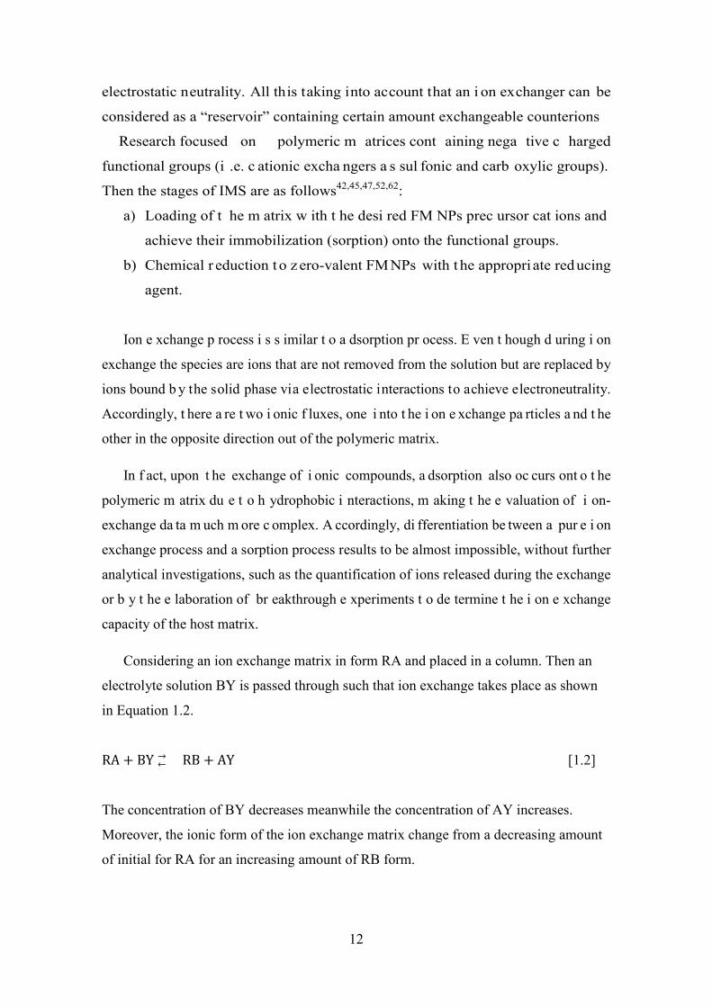
The end result is that at the top layers of Matrix are exhausted followed by an exchange
zone across which the initial equivalent concentration C, of ion B is reduced to zero
whilst the concentration of ion A increases to C,. Below the exchange zone
(breakthrough) ideally, the ion exchange matrix is entirely in the A form and in
equilibrium with the effluent AY (no exchange takes place) as shown in Figure 1.9.
The area above the breakthrough curve up to the breakthrough point VBC0 is the
matrix loading of the absorbed ion B. Thus, taking into account the total amount of B
ions exchanged can be calculated and the IEC in miliequivalents per gram (meq/g) of
the matrix can be calculated as the weight of matrix placed in the column and the
concentrations are known values.
The breakthrough curve is little affected by the equilibrium and, all other
considerations. Under conditions of constant column geometry and on presentation rate,
the profile of the exchange zone and therefore the breakthrough curve remains
unchanged with time or column length and is said to show a constant pattern as show in
Figure 1.10.
VB
𝑪𝑪𝑩𝑩𝑪𝑪𝟎𝟎
Breakthrough
Zona B
Zone A
Figure 1.9 breakthrough profile scheme for ion exchange.
13
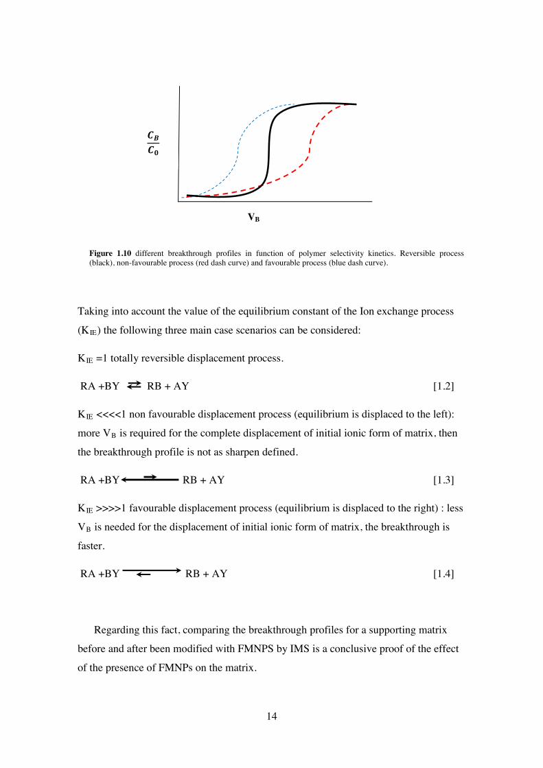
Taking into account the value of the equilibrium constant of the Ion exchange process
(KIE) the following three main case scenarios can be considered:
KIE =1 totally reversible displacement process.
RA +BY RB + AY [1.2]
KIE <<<<1 non favourable displacement process (equilibrium is displaced to the left):
more VB is required for the complete displacement of initial ionic form of matrix, then
the breakthrough profile is not as sharpen defined.
RA +BY RB + AY [1.3]
KIE >>>>1 favourable displacement process (equilibrium is displaced to the right) : less
VB is needed for the displacement of initial ionic form of matrix, the breakthrough is
faster.
RA +BY RB + AY [1.4]
Regarding this fact, comparing the breakthrough profiles for a supporting matrix
before and after been modified with FMNPS by IMS is a conclusive proof of the effect
of the presence of FMNPs on the matrix.
VB
𝑪𝑪𝑩𝑩𝑪𝑪𝟎𝟎
Figure 1.10 different breakthrough profiles in function of polymer selectivity kinetics. Reversible process (black), non-favourable process (red dash curve) and favourable process (blue dash curve).
14
1.3.2 IMS of BFNCs with favourable distribution due to Donnan Exclusion Effect
DEE refers to the impossibility to penetrate deeply in a matrix when there is a
coincidence between the charge of the outside ions (e.g. from the reducing agent)
and t he ones of t he funct ional gr oups o n t he pol ymer surfac e. T hus, a n
equilibrium between ion concentration (either functional groups or from metal or
reducing agent solution) and electrostatic repulsion takes place.
When I MS i s coupl ed w ith Donnan E xclusion E ffect (DEE)39,63,64 predicts t hat
the use of negat ively charged reduc ing ag ents such as N aBH4, l eads t o t he
location of the FMNPs mainly on the surface of the supporting matrix due to the
electrostatic repulsion between the BH4- and the functional groups o f the matrix
(negatively charged as well).
Equations 1.5 and 1. 6 show the example of I MS stages for t he synthesis of A g-
FMNPs on a sulfonic cationic exchanger.
Metal loading stage:
R-SO3−Na+ + Ag+ → R-SO3
−Ag+ + Na+ [1.5]
Metal reduction stage
R-SO3−Ag+ + NaBH4 + 3H2O → R-SO3
−Na+ + 7/2H2 + B(OH)3 + Ag0 [1.6]
Considering the case of a nion exchange matrices and t he IMS of Ag-FMNPs,
the first stage of IMS coupled with DEE is the sorption of the reducer anions on
the positively charged functional groups40,51,62 of the matrix (Equation 1.7). The
second st age ( Equation 1.8) i s t he t reatment of t he pol ymer w ith sol ution of
positively charged metal ions. Their rejection by the matrix bearing the charge of
the same sign does not allow them to deeply penetrate into the polymer and their
interaction with reducing agent proceeds (as in the previous case) near the surface
of the support.
R-(R4-N)+Cl- + NaBH4 → R-(R4-N)+BH4- + NaCl [1.7]
R-(R4-N)+BH4 + AgNO3 + 3H2O → R-(R4-N)+NO3-Ag0 + 7/2 H2 + B(OH)3
[1.8]
15

It seems important to emphasize that both versions of IMS technique lead to
the most favourable distribution of FMNPs near the surface of BFNCs as seen in
Figure 1.11, what is particularly important in practical application of such
materials for complex water treatment. Note that similar procedure has been also
applied for the synthesis of metal oxide nanoparticles inside ion exchange resins
for removal of arsenic from water65 and for the preparation of heterogeneous
catalysts.62
Figure 1.11: Scheme of ion exchange processes during stage 1 IMS in A) cationic exchanger, B) anionic exchanger and the final FMNPs favourable distribution on the surface of the BFNCs C) proved by cross section SEM images in which white zone show FMNPs layer.
After finishing the metal reduction the functional groups of the supporting
matrix appear to be converted back into the initial ionic form (Na-form in the first
and NO3-form and further treatment to obtain Cl-form for the anionic exchanger).
This means that in both cases IMS reactions can be repeated without any
additional pretreatment of the ion exchanger52,56,62. This could result in the
accumulation of a higher amount or increase of the thickness of the FMNPs when
the same metal precursor is used as indicated in Figure 1.12.
16

Figure 1.12: Increase of FMNPs layer thickness due to consecutive IMS cycles.
The main difference between these two versions of IMS method consists in the
type of the matrix-immobilized reagent, which is the desired metal ion (FMNPs
precursor) in on or other version.
The IMS technique is characterized by the following important features:
1) The formation of FMNPs on stabilizing matrix does not influence the IEC,
what is confirmed by the results of determination of this value before and
after IMS of FMNPs. This means that the functional groups are not
blocked by the formed nanoparticles and can participate in the ion-
exchange reactions(offering bifunctionality to the novel added value
material)
2) After carrying out the IMS of FMNPs the functional groups of the matrix
in both versions of IMS technique appear to be simultaneously regenerated
(i.e., converted back into the initial ionic form). This means that metal-
loading-reduction cycles can be repeated to accumulate the desired amount
of FMNPs in the supporting polymer.
All above features can be considered as definite advantages of the developed
in our studies IMS coupled with DEE. Technique as it appears to be applicable
for the synthesis of FMNPs supported on any type of functional ion exchange
reactive matrices. The reactive matrices presented in this PhD Thesis are listed in
Table 1.2:
Consecutive IMS cycles
17
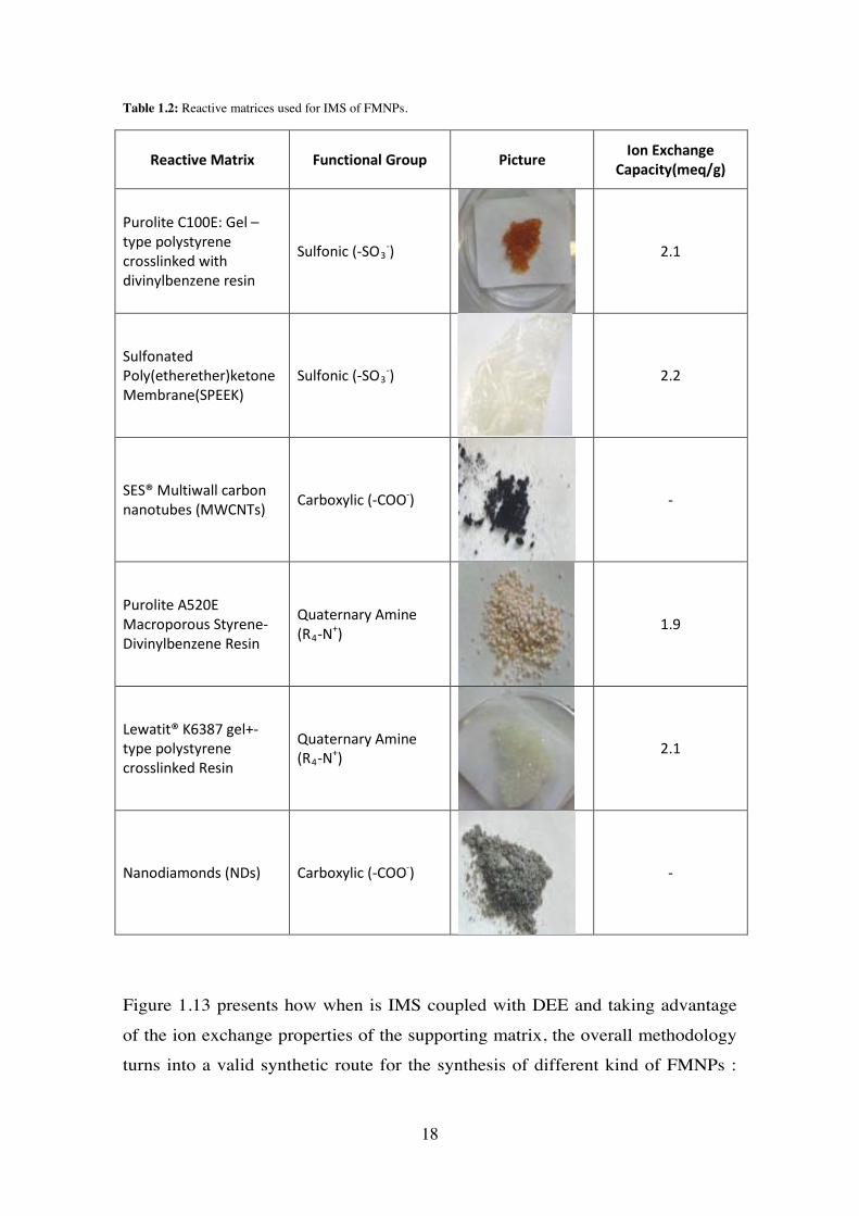
Table 1.2: Reactive matrices used for IMS of FMNPs.
Reactive Matrix Functional Group Picture Ion Exchange Capacity(meq/g)
Purolite C100E: Gel – type polystyrene crosslinked with divinylbenzene resin
Sulfonic (-SO3-)
2.1
Sulfonated Poly(etherether)ketone Membrane(SPEEK)
Sulfonic (-SO3-)
2.2
SES® Multiwall carbon nanotubes (MWCNTs) Carboxylic (-COO-)
-
Purolite A520E Macroporous Styrene-Divinylbenzene Resin
Quaternary Amine (R4-N+)
1.9
Lewatit® K6387 gel+-type polystyrene crosslinked Resin
Quaternary Amine (R4-N+)
2.1
Nanodiamonds (NDs) Carboxylic (-COO-)
-
Figure 1.13 presents how when is IMS coupled with DEE and taking advantage
of the ion exchange properties of the supporting matrix, the overall methodology
turns into a valid synthetic route for the synthesis of different kind of FMNPs :
18
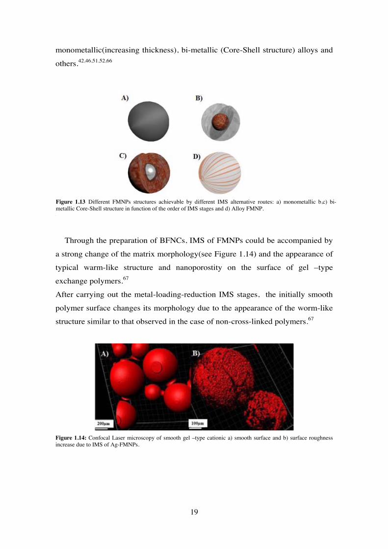
monometallic(increasing thickness), bi-metallic (Core-Shell structure) alloys and
others.42,46,51,52,66
Figure 13:
Through the preparation of BFNCs, IMS of FMNPs could be accompanied by
a strong change of the matrix morphology(see Figure 1.14) and the appearance of
typical warm-like structure and nanoporostity on the surface of gel –type
exchange polymers.67
After carrying out the metal-loading-reduction IMS stages, the initially smooth
polymer surface changes its morphology due to the appearance of the worm-like
structure similar to that observed in the case of non-cross-linked polymers.67
Figure 1.14: Confocal Laser microscopy of smooth gel –type cationic a) smooth surface and b) surface roughness increase due to IMS of Ag-FMNPs.
Figure 1.13 Different FMNPs structures achievable by different IMS alternative routes: a) monometallic b,c) bi-metallic Core-Shell structure in function of the order of IMS stages and d) Alloy FMNP.
19
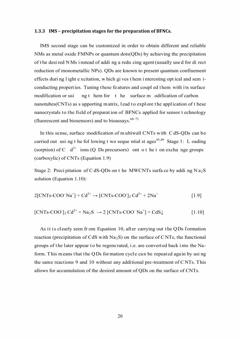
1.3.3 IMS – precipitation stages for the preparation of BFNCs.
IMS second stage can be customized in order to obtain different and reliable
NMs as metal oxide FMNPs or quantum dots(QDs) by achieving the precipitation
of t he desi red N Ms i nstead of addi ng a redu cing agent (usually use d for di rect
reduction of monometallic NPs). QDs are known to present quantum confinement
effects duri ng l ight e xcitation, w hich gi ves t hem i nteresting opt ical and sem i-
conducting propert ies. Tuning t hese fe atures and coupl ed t hem with i ts surface
modification or usi ng t hem for t he surface m odification of carbon
nanotubes(CNTs) as s upporting matrix, l ead t o expl ore t he appl ication of t hese
nanocrystals to the field of preparat ion of BFNCs applied for sensor t echnology
(fluorescent and biosensors) and to bioassays.68–71
In this sense, surface modification of m ultiwall CNTs with C dS-QDs can be
carried out usi ng t he fol lowing t wo seque ntial st ages45,49 Stage 1: L oading
(sorption) of C d2+ ions (Q Ds precursors) ont o t he i on excha nge groups
(carboxylic) of CNTs (Equation 1.9)
Stage 2: Preci pitation of C dS-QDs on t he MWCNTs surfa ce by addi ng N a2S
solution (Equation 1.10):
2[CNTs-COO- Na+] + Cd2+ → [CNTs-COO-]2 Cd2+ + 2Na+ [1.9]
[CNTs-COO-]2 Cd2+ + Na2S → 2 [CNTs-COO- Na+] + CdS↓ [1.10]
As i t i s clearly seen fr om Equation 10, after carrying out the QDs formation
reaction (precipitation of CdS with Na2S) on the surface of C NTs, the functional
groups of t he later appear t o be regene rated, i.e. are convert ed back i nto the Na-
form. This means that the QDs formation cycle can be repeated again by usi ng
the same reactions 9 and 10 without any additional pre-treatment of C NTs. This
allows for accumulation of the desired amount of QDs on the surface of CNTs.
20
1.3.4 IMS – galvanic displacement stages for preparation of BFNCs.
Au FMNPs have made them focus of interested in the recent years due to their
optical features. Their feasible applications are in fields as: biological
microscopy, medicine and (bio) sensors. Therefore is a fact the importance to
develop an efficient approach for their synthesis for their different possible
morphologies (nanoprisms, nanocubes). Regarding this, IMS coupled with DEE
and posterior galvanic displacement reaction, allows the preparation of BFNCs
with such FMNPs (eg. AgAu-FMNPs). 19,37,72–76
The driving force for the galvanic displacement reaction arises from the
difference in half-cell potentials between the metal ions to be reduced and the
substrate to be oxidized.76,77 To ahieve the deposition of metal nanoparticles, the
half-cell potential of the reduced species must be higher than the one of the
oxidized substrate. This is the case for Ag and Au. Then, the synthesis of AgAu-
FMNPs is possible by IMS-galvanic displacement route, bringing the possibility
an easy way to synthesize Au-FMNPs on cationic exchangers using Ag-FMNPs
as “sacrifice” NPs. Considering the tuned IMS of Ag-FMNPs to obtain certain
defined nano and microstructures78–80 as nano-micro cubes, as shown in Figure
1.15
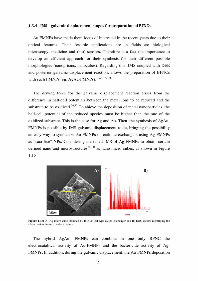
Figure 1.15: A) Ag micro cube obtained by IMS on gel type cation exchanger and B) EDS spectra identifying the silver content in micro cube structure.
The hybrid AgAu- FMNPs can combine in one only BFNC the
electrocatalitcal activity of Au-FMNPs and the bactericide activity of Ag-
FMNPs. In addition, during the galvanic displacement, the Au-FMNPs deposition
200nmSilver
A) B)
0 2 4 µm
21
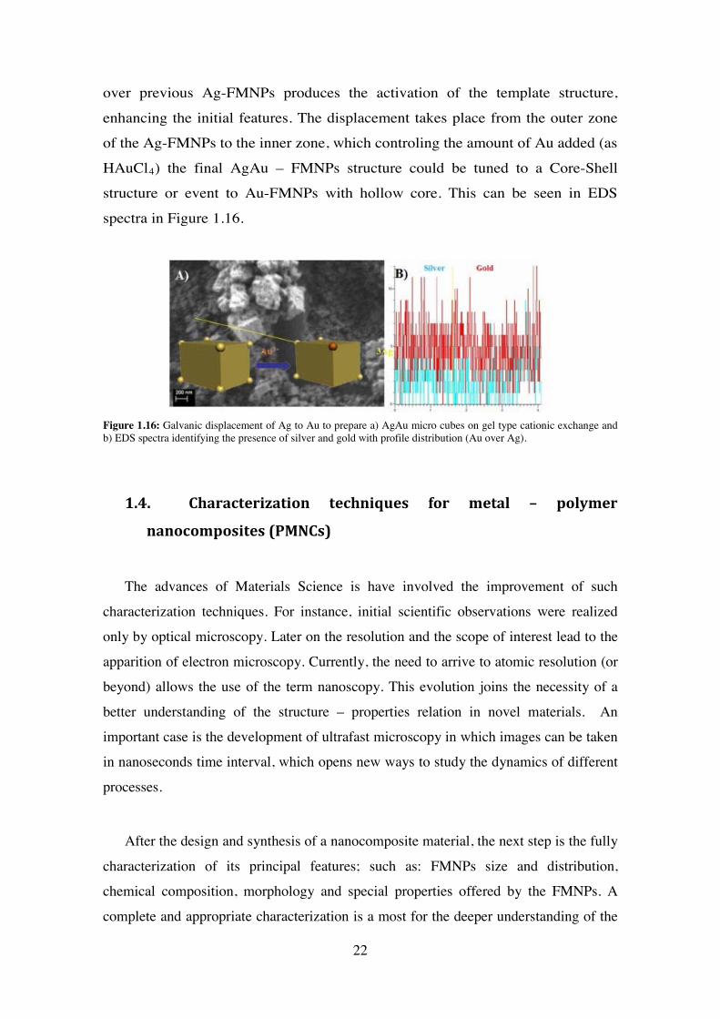
over previous Ag-FMNPs produces the activation of the template structure,
enhancing the initial features. The displacement takes place from the outer zone
of the Ag-FMNPs to the inner zone, which controling the amount of Au added (as
HAuCl4) the final AgAu – FMNPs structure could be tuned to a Core-Shell
structure or event to Au-FMNPs with hollow core. This can be seen in EDS
spectra in Figure 1.16.
Figure 1.16: Galvanic displacement of Ag to Au to prepare a) AgAu micro cubes on gel type cationic exchange and b) EDS spectra identifying the presence of silver and gold with profile distribution (Au over Ag).
1.4. Characterization techniques for metal – polymer
nanocomposites (PMNCs)
The advances of Materials Science is have involved the improvement of such
characterization techniques. For instance, initial scientific observations were realized
only by optical microscopy. Later on the resolution and the scope of interest lead to the
apparition of electron microscopy. Currently, the need to arrive to atomic resolution (or
beyond) allows the use of the term nanoscopy. This evolution joins the necessity of a
better understanding of the structure – properties relation in novel materials. An
important case is the development of ultrafast microscopy in which images can be taken
in nanoseconds time interval, which opens new ways to study the dynamics of different
processes.
After the design and synthesis of a nanocomposite material, the next step is the fully
characterization of its principal features; such as: FMNPs size and distribution,
chemical composition, morphology and special properties offered by the FMNPs. A
complete and appropriate characterization is a most for the deeper understanding of the
22
behaviour of t he N anocomposite m aterial; a nd t herefore i ts f urther s ynthesis
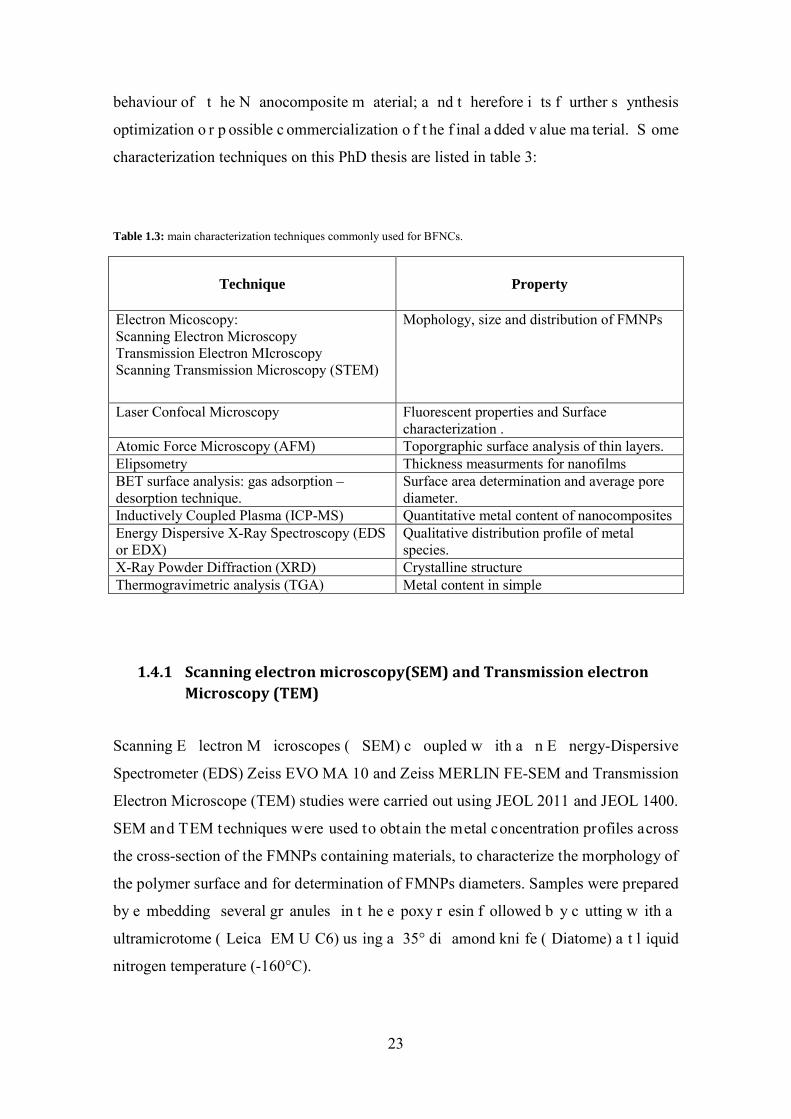
optimization o r p ossible c ommercialization o f t he f inal a dded v alue ma terial. S ome
characterization techniques on this PhD thesis are listed in table 3:
Table 1.3: main characterization techniques commonly used for BFNCs.
Technique Property
Electron Micoscopy: Scanning Electron Microscopy Transmission Electron MIcroscopy Scanning Transmission Microscopy (STEM)
Mophology, size and distribution of FMNPs
Laser Confocal Microscopy Fluorescent properties and Surface characterization .
Atomic Force Microscopy (AFM) Toporgraphic surface analysis of thin layers. Elipsometry Thickness measurments for nanofilms BET surface analysis: gas adsorption – desorption technique.
Surface area determination and average pore diameter.
Inductively Coupled Plasma (ICP-MS) Quantitative metal content of nanocomposites Energy Dispersive X-Ray Spectroscopy (EDS or EDX)
Qualitative distribution profile of metal species.
X-Ray Powder Diffraction (XRD) Crystalline structure Thermogravimetric analysis (TGA) Metal content in simple
1.4.1 Scanning electron microscopy(SEM) and Transmission electron Microscopy (TEM)
Scanning E lectron M icroscopes ( SEM) c oupled w ith a n E nergy-Dispersive
Spectrometer (EDS) Zeiss EVO MA 10 and Zeiss MERLIN FE-SEM and Transmission
Electron Microscope (TEM) studies were carried out using JEOL 2011 and JEOL 1400.
SEM and TEM techniques were used to obtain the metal concentration profiles across
the cross-section of the FMNPs containing materials, to characterize the morphology of
the polymer surface and for determination of FMNPs diameters. Samples were prepared
by e mbedding several gr anules in t he e poxy r esin f ollowed b y c utting w ith a
ultramicrotome ( Leica EM U C6) us ing a 35° di amond kni fe ( Diatome) a t l iquid
nitrogen temperature (-160°C).
23
1.4.2 Scanning Transmission Microscopy ((S)-TEM)
(S)-TEM i mages w ere obtained us ing F EI T ecnai F 20 S /TEM f rom th e E lectron
Microscopy Facilities of Institut Català de Nanociència I Nanotecnologia (ICN2). This
device of fers hi gh-resolution i maging, dow n t o a tomic s cale, of t he s tructure a nd
morphology of s amples i n T EM a nd S TEM m odes up t o 200kV ope rating vol tage.
Moreover the chemical analysis at nanometer level and chemical mapping via Energy
Dispersive X-ray Spectroscopy can be achieved.
1.4.3 Laser Confocal Scanning Microscopy (LCSM)
Real time Intermatrix Synthesis ( IMS) o f Ag f unctional me tal n anoparticles
(FMNPs): surface modification of gel-type polymer: 4-D time-lapse imaging showing
the IMS of A g-FMNPs on a ge l-type cationic exchange r esin. N ote a n i ncrease o f
FMNPs l ayer t hickness i n t he t ime a nd t he di fferent roughness of t he s urface of
polymer. A t t = 0 m in, there i s a f ree A g-FMNPs w ith a hom ogeneous a nd s mooth
surface. A t t = 7 m in, t he m odified A g-FMNPs g el-type pol ymer s howed a
heterogeneous surface area as worm-like structures.
Confocal m easurements for m orphology c hanges i n a ge l-type pol ymer. S amples
were m ounted on bot tom-glass c ulture di shes (MatTek C orp., A shland) a nd w ere
examined using a TCS-SP5 (Leica Microsystems, Heidelberg, Germany) confocal laser
scanning microscope. Images were t aken us ing a 10x/0.4 P lan Apochromat obj ective.
Both free Ag-FMNPs and modified Ag-FMNPs gel-type polymer were excited with an
Argon laser (488 nm). To determine the 3D structure, stacks of 50 to 100 sections were
collected every 3 μm along the material’s thickness. Three-dimensional m odels w ere
generated from the xyz series using the Imaris X64 v. 6.2.0 s oftware (Bitplane; Zürich,
Switzerland).
The i ncrease o f F MNPs m etal l ayer t hickness w ith t ime w as ev aluated u sing 4 D
time-lapse. P rojections were obt ained f rom 40 s ections ( z-step = 4 μm). The stack of
images was acquired every 7 s for 8 m in. To determine the FMNPs layer localization
different projections were generated f rom the x yz series vs . t ime us ing Imaris X64 v.
6.2.0 software (Bitplane, Zürich, Switzerland).
24
1.4.4 Spectroscopic Ellipsometry
It is an optical technique used for the determination of dielectric properties (complex
refractive i ndex or di electric f unction), r oughness a nd t hickness of t hin f ilms. T his i s
achieved by detecting the variation of angle of an incident known radiation source on
the s ample. T he m ain dr awback of t his t echnique i s t he ne ed of m odelling t he da ta
obtained to fully understand the change of polarization of the incident beam of light to
the sample and consequently to explain the influence in sample features involved in this
process.
1.4.5 Brunauer – Emmet – Teller (BET) surface analysis: gas adsorption – desorption technique.
This technique is widely used for the characterization of porous materials because of
the di rect pr oportion of t he a dsorbed g as a nd t he s urface area of t he material. B ET
theory predicts the amount of gas adsorbed in certain surface. The specific surface area
and t he por osity m easurements w ere carried out b y us ing B ET t echnique on
Micromeritics A SAP-2000 e quipment f rom Institut de C iències de ls Materials de
Barcelona (ICMAB). N anocomposite s amples were h eated and de gassed w ith N 2 t o
remove previous absorbed gas molecules. After that, samples were introduced to a N2
flow to detect the adsorption and desorption isotherms at 293K.
1.4.6 Inductively Coupled Plasma (ICP-MS)
A sample of about 10mg of FMNPs-containing material was immersed in aqua regia
(1 m L) t o c ompletely di ssolve t he pa lladium b y oxi dation. T he s olution w as f iltered
through a 0.22 μm Millipore f ilter a nd d iluted f or me tal c ontent q uantification b y
Induced C oupled P lasma O ptical E mission Spectrometry, ICP–OES (Iris I ntrepid I I
XSP s pectrometer Thermo E lectron C o) and ICP-MS ( Agilent 7500) . T he a verage
uncertainty of metal ions determination was less than 2% in all cases.
25
1.4.7 Thermogravimetric analysis (TGA)
In T GA t he w eight of a s ample i s m easured as f unction of s ample
termperature(scanning mode) or as function of t ime(isothermal mode). It i s based on
the decomposition and thermal stability of a m aterial under different temperatures. The
mass change is detected and leads the identification of components of the sample.
Thermogravimetric analysis were p erformed on a N etzsch i nstrument, m odel
STA 449 F1 Jupiter®, with a flow of air. A ~20 mg sample was heated to 1000 ºC at 10
ºC/min, us ing f low of a ir. T he m ass of t he s ample w as c ontinuously m easured as a
function of temperature and the rate of weight loss (d.t.g.) was automatically recorded
1.5. Current and future applications of BFNCs prepared by IMS.
Recently, nanocom posite m aterials have been w idely used fo r opt ical,
electrical and m agnetic a pplications. T he p reparation of nove l and effi cient
nancomposites is a bi g challenge, and so i t is the central aspect for research for
scientists. On one hand the preparation methodology is essential to obtain FMNPs
with a favourable distribution over a polymeric support. This supports offer the
stability for t he FMNPs t o avoi d probl ems as aggl omeration and rel ease t o t he
media. 45–48,52,62,67,81,82The feasi ble appl ications of B ifunctional nanocomposites,
such as the ones composed by FMNPs and an ion exchange matrix (resins, fibres,
membranes) cover a br oad range beca use of t he dual features of t he final hybrid
material; co mbining i on e xchange propert ies w ith t he ones of the FM NPs
synthesized on the polymer matrix
The t ime has co me to the application of t hese materials on i nnovative fi elds
and industrial processes. Some new applications gaining interest in recent years
are in terms of biomedical, catalytic, separation, sensor, microfabrication and fuel
technologies.
The suitability of the BFNCs for a certain use depends on t he FMNPs and the
capability of t he re agents t o a ccess t hem. T hen, t he physi cal chem istry
26
parameters of t he support must allow the mass transfer and diffusion of rea gents
through it. This fact is particularly important in sensor and biosensor field, the
preparation of novel materials for com plex w ater t reatments and bac tericide
assays, as well for heterogeneous Nanocatalysis.
For bactericide assays, the bacteria interact mainly with the FMNPs located at
or near the BFNCs surface. In t he case of cat alytic processes, the kinetics of t he
catalytic react ion st rongly depends on t he ac cessibility of cat alyst FMNPs for
reactants. For this reason the surface distribution of catalytically active MNPs has
to substantially enhance their properties.51,52
One more aspect to be considered besi des t he FMNPs distribution w hen
designing t he m odification of i on exc hange m aterials for t he preparat ion of
BFNCs is that although MNPs in the final nanocomposite are st rongly captured
by t he pol ymer, som e of t hem coul d escape i nto t he m edium und er t reatment
(water or reaction mixture).
IMS of FMNPs with a core-shell structure consisting of a superparam agnetic
core coat ed w ith t he functional m etal she ll of t he minimal t hickness, w hich
provides t he m aximal bact ericide or cat alytic act ivity. T he super paramagnetic
nature of FM NPs provi des an addi tional l evel of t he m aterial saf ety as M NPs
leached from the polymer matrix can be easi ly captured by the magnetic traps to
completely prevent any post -contamination of t he t reated w ater. In t he c ase o f
catalytic appl ications of pol ymer-metal nan ocomposites t his fea ture of M NPs
allows for their easy recovery for reuse or recycling what is particularly important
in case of nobl e M NPs. T he presence of M NPs does not bl ock t he func tional
groups of t he so t hat t he BFNCs can be a lso used for t he rem oval of som e
undesired i ons (e. g. , hardness i ons, i ron, n itrates, et c.) from t he water w hat i s
particularly important in the case of complex water treatment.62,83
27

1.5.1 Heterogeneous Catalysis
BFNCs have e merged as sust ainable al ternatives t o convent ional cat alysts.
Their nano -sized c omponents i ncrease t he e xposed surface area o f t he act ive
component of the catalyst, thereby enhancing the contact between reactants and
catalyst.
Some key point to consider are the capability to separate the catalyst from the
reaction media once t he ca talytic process i s over and t he efficient selectivity of
the cat alyst for t he desired re action. T hese feat ures c an be t uned up by
customizing t he che mical com position and m orphology of FM NPS i n hybri d
BFNCs materials.
Some rel evant aspect s and chal lenges of het erogeneous N anocatalysis a re
presented in Figure 1.17.
Regarding the fact that t he fi nal N anocomposite material presents both
properties of t he NMs a nd t he pol ymeric matrix, i ts appl ication for cat alysis i s
favoured by t he feasi bility t o separat e t he catalyst fro m re action m edia by a
simple physical filtration step. In addition; the synthesis of FMNPs with magnetic
core and a cat alytic s hell, m akes possi ble a s w ell t o se parate t he BFNCs by
applying a magnetic trap; as indicated in Figure 1.18.
Heterogeneous Nanocatalysis
High surface area
pseudo homogeneous Catalysis
Tune up featurs of
nanocatalysts
Easy separation methodos
Figure 1.17: Advantages of heterogeneous nanocatalysis.
28
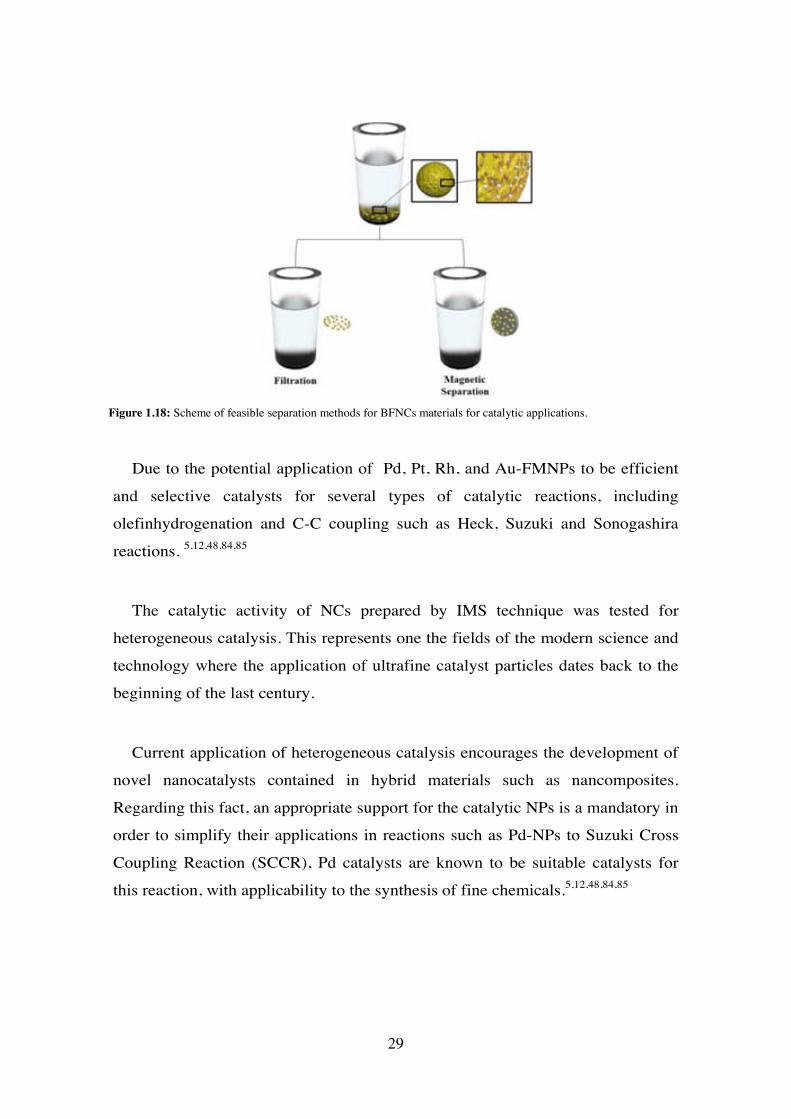
Due to the potential application of Pd, Pt, Rh, and Au-FMNPs to be efficient
and selective catalysts for several types of catalytic reactions, including
olefinhydrogenation and C-C coupling such as Heck, Suzuki and Sonogashira
reactions. 5,12,48,84,85
The catalytic activity of NCs prepared by IMS technique was tested for
heterogeneous catalysis. This represents one the fields of the modern science and
technology where the application of ultrafine catalyst particles dates back to the
beginning of the last century.
Current application of heterogeneous catalysis encourages the development of
novel nanocatalysts contained in hybrid materials such as nancomposites.
Regarding this fact, an appropriate support for the catalytic NPs is a mandatory in
order to simplify their applications in reactions such as Pd-NPs to Suzuki Cross
Coupling Reaction (SCCR), Pd catalysts are known to be suitable catalysts for
this reaction, with applicability to the synthesis of fine chemicals.5,12,48,84,85
Figure 1.18: Scheme of feasible separation methods for BFNCs materials for catalytic applications.
29
1.5.2 Electrochemical Sensors:
A chemical sensor is an analytical device used to obtain chemical information
from a sample. These are widely used for the detection and quantification of
organic and i norganic com pounds for cl inical, bi omedical and e nvironmental
purposes.86–90
Some basic requi rements for a sensor i nclude st ability, sel ectivity, and hi gh
response rat e for t he analyte signal, l ong l ife cycl e, l ow energy and anal yte
consumption.
Specifically, amperometric sensors are based on the application of and extern
potential t hat cause s an el ectronic t ransference bet ween t he w orking el ectrode
and t he speci es i n t he sol ution und er st udy. T he current i s pro portional t o t he
concentration of the analyte, it goes through an electrochemical cell that contains
electroactive species. Thus, the quantitative detection of the analyte is achievable
even at l ow concentrations l ike part s per billion (ppb). A sui table analyte for a
certain electrode is the one t hat can be electrochemically oxidized or reduced on
the electrode surface.
One drawback of amperometric sensors i s their selectivity and their relatively
long t ime response. T he depend ence be tween current i ntensity and anal yte
concentration is described by the following Equation 1.11: 91–93
𝑖 = 𝑛𝐹𝐴𝐷𝑎𝐶𝑎𝛿
= 𝑘𝐴𝐶𝐴 [11]
i represent s t he i ntensity, A re presents t he surfa ce area, n i s t he num ber of
electron m oles per an alyte mole i nvolved i n t he redox proc ess, F is Faraday’s
constant, D a i s t he di ffusion coeffi cient, C a i s concent ration of e lectroactive
species,, δ is the thickness of diffusion layer and kA is the equivalent of
nFADa/δ.
30
The use of FM NPs for t he modification of amperometric sensors offers great
advantages as t he e nhancement of mass t ransference rat e t hrough t he pol ymer
matrix and the increase in the surface area of the nanoelectrocatalyst. 91
One simple way for the electrode modification using BFNCs i s the
incorporation of FMNPs nanocomposites containing noble metal NPs such as Pd,
Au or Pt . Despite of the precursor reagent price, the great stability and oxidation
resistance of t hese m etals m ake them m ore t han a good alternative for t he
preparation of amperometric sensors. and their electroactive features and catalytic
behaviour for some chemical reactions.92–94
In addition to these advantages, the modification of sensors w ith nanocrystals
as FM NPs coul d i mply t hermal evaporat ion, e lectroless de position by gal vanic
replacement, MNPs hydrosol absorption or electrochemical deposition. 95–97
The possi ble aggregat ion of t he FM NPs l imits t heir appl ication i n
electrochemical syst ems. Due t o this fact , t he preparat ion of F MNPs must
provide an ext ra l evel of st ability and a favourabl e di stribution in t he fi nal NC
electrode material45. Regarding this, the IMS technique becomes a v alid FMNPs
preparation methodology. IMS takes advantage of the ion exchange properties of
the support m atrix (e. g. sul fonic resi ns or membranes, carbon na notubes) for
consecutive loading and reduction processes during the synthesis of FMNPs with
a favourable distribution in the final composite material..
For instance, taking advantage of the solubility of some polymeric membranes
in organi c sol vents, the electrode modification can be carri ed out by t he
preparation of NPs ink. The ink is dropped on the surface of the sensor and let
dry due to the volatility of the solvent, where the FMNPs stay attached on sensor
surface.
By i ncorporating FM NPs, t he el ectrochemical syst em subst antially i mproves
its the electron transfer47. Among transfer mechanisms involved in sensors, some
others)
31

Moreover, the, the insertion of FMNPs within a matrix containing immobilized
enzymes, allows increasing substantially the conductivity of the matrix and
therefore the transfer between the enzyme molecules to the surface of the
electrode. The same effect takes place by decreasing the distance electrons
hop(see Figure 1.19)
Furthermore, it should be noted that the incorporation of enzymes into the
biosensors makes them a highly selective devices, which is owned one of the
main drawbacks of amperometric sensors.
Figure 1.19: Scheme of the enhanced electronic transfer of modified electrodes with FMNPs.
An example of the feasibility of IMS prepared NCs for sensor applications is a
glucose biosensor prepared by using the layer-by-layer deposition technique.
The modification of Graphite-epoxy composite electrodes (GECEs) with Core-
Shell Pt@Cu-MNPs on Sulfonated polyetheretherketone (SPEEK) membrane
which was sequentially treated with polyethylenimne (PEI) and Glucose oxidase
(GOx) solutions.98,99
The sensitivity of biosensor at the same enzyme content (PEI-GOx layers)
appears to strongly depend on the thickness of Pt-shell. This means that the
32

thickness of the catalytically active shell of MNPs can be used as an additional
parameter for enha ncing t he bi osensor perform ance. T his concl usion fol lows
from a high sensitivity of Pt@Cu toward hydrogen peroxide, which is one of t he
by-products of t he e nzymatic reac tion proce eding i n t he course of gl ucose
detection. The amperometric sensors prepared by modification of GECE with
FMNPs demonstrate a high sensitivity toward hydrogen peroxide as can be seen
in Figure 1.20.
Figure 17
1.5.3 Bactericide Activity
There are about 800 m illion people in the world which do not have access to
clean and potable water. Therefore, the importance of potable water for people in
some countries dictates the need for t he development of innovative technologies
and materials for t he p roduction of safe pot able water. This type of appl ication
can be a perfect for the NCs for water treatment and bactericide assays.
Furthermore, t he use of NCs can al so h elp t o sol ve one of the m ajor
operational problems associated with water treatment technology: the biofouling.
With the coating of polymeric membranes w ith A g-NPs, the accumulation of
microorganism and t heir furt her m ultiplication i n t he m aterial i s i mpeded, t hus
the operat ional propert ies of t he NCs are kep t. Thus, t he bactericide act ivity o f
AgAu-cubic m icrostructure c ontaining com posite m aterials is t ested as a nove l
bactericidal NC. An increasing amount of A gAu-NCs (102 m gAg x g -1 BFNC
Figure 1.20: Calibration curves of electrochemical detection of H2O2 concentration with Pt@Cu, Pt- and Cu-FMNP composite S PEEK m embranes Experimentalconditions: p otential: –250 m V; 0. 1 M a cetate buf fer(Adapted from Muraviev et.al98)
33
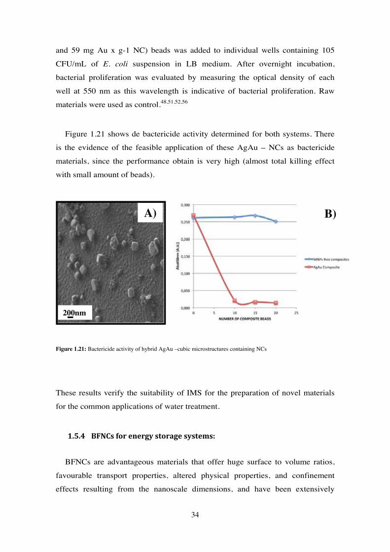
and 59 mg Au x g-1 NC) beads was added to individual wells containing 105
CFU/mL of E. coli suspension in LB medium. After overnight incubation,
bacterial proliferation was evaluated by measuring the optical density of each
well at 550 nm as this wavelength is indicative of bacterial proliferation. Raw
materials were used as control.48,51,52,56
Figure 1.21 shows de bactericide activity determined for both systems. There
is the evidence of the feasible application of these AgAu – NCs as bactericide
materials, since the performance obtain is very high (almost total killing effect
with small amount of beads).
Figure 1.21: Bactericide activity of hybrid AgAu –cubic microstructures containing NCs
These results verify the suitability of IMS for the preparation of novel materials
for the common applications of water treatment.
1.5.4 BFNCs for energy storage systems:
BFNCs are advantageous materials that offer huge surface to volume ratios,
favourable transport properties, altered physical properties, and confinement
effects resulting from the nanoscale dimensions, and have been extensively
200nm
A) B)
34

studied for ene rgy-related a pplications such as sol ar cel ls, cat alysts,
thermoelectrics, l ithium i on bat teries, supe rcapacitors, and hydrogen st orage
systems with high solar energy conversion efficiencies at low fabrication cost.
These materials can be tailored to harvest sun light over a b road range of t he
spectrum, while plasmonic structures offer effective ways to reduce the thickness
of l ight-absorbing l ayers. M ultiple exci ton generation, si nglet ex citon fi ssion,
photon dow n-conversion, and photon u p-conversion real ized in n anostructures,
create si gnificant i nterest for harvest ing underut ilized ul traviolet and c urrently
unutilized infrared photons. 100 101
1.6. Concluding Remarks:
BFNCs demonstrate t o have i nteresting fe atures consi sting i n t he m utual
influence of com ponents (support ing m atrix and NPs) on each ot her. For
example, the m atrix provides stabilization of FMNPs, preventing their
aggregation and uncontrollable growth. On the other hand, FMNPs can react with
polymer chai ns se rving as a sort of cross -linking agent s, w hat re sults i n t he
appearance of nanoporosity in gel type polymers. Their bifunctionality represents
another i nteresting fea ture of t hese materials.. On one hand i t i s det ermined by
the functionality of the hosting polymer (e.g., ion exchanger), while on the other
it is also determined by the properties of FM NPs (e.g., bactericide or cat alytical
activity). From this viewpoint the structural features of t he BFNCs material start
to pl ay t he key rol e i n t he fi eld of funct ional m aterials for c urrent and fut ure
applications. T herefore, t he m ost favourabl e spat ial a nd si ze di stribution of
FMNPs in NCs should be near the surface is one of the advantages of IMS as a
green preparation methodology of NPs and BFNCs. Consequently, studying how
IMS provides the most favourable distribution of the NPs in the BFNCs, the role
of DEE, the possible effects on the initial ion exchange properties of the support
matrix and furt her ap proaches of I MS; are descri bed and di scussed i n t he
following sections.
35
References
(1) Fhalman, B. Materials Chemistry; Second Edi.; Springer: New York, 2011.
(2) Zang, J.; Wang, Y.; Bian, L.; Zhang, J.; Meng, F.; Zhao, Y.; Ren, S.; Qu, X. Surface Modification and Electrochemical Behaviour of Undoped Nanodiamonds. Electrochim. Acta 2012, 72, 68–73.
(3) Saha, K.; Agasti, S. S.; Kim, C.; Li, X.; Rotello, V. M. Gold Nanoparticles in Chemical and Biological Sensing. Chem. Rev. 2012, 112, 2739–2779.
(4) Binder, W. H.; Sachsenhofer, R. “Click” Chemistry in Polymer and Materials Science. Macromol. Rapid Commun. 2007, 28, 15–54.
(5) Domènech, B.; Bastos-Arrieta, J.; Alonso, A. Bifunctional Polymer-Metal Nanocomposite Ion Exchange Materials. In Ion Exchange Technologies; Kilislioglu, A., Ed.; InTech, 2012; pp. 35–72.
(6) Plieth, W. Electrochemistry for Materials Science; First Edit.; Elsevier: The Netherlands, 2008.
(7) Sanchez, C.; Shea, K. J.; Kitagawa, S. Applications of Advanced Hybrid Organic–inorganic Nanomaterials: From Laboratory to Market. Chem. Soc. Rev. 2011, 40, 696–753.
(8) Van Hove, M. a. From Surface Science to Nanotechnology. Catal. Today 2006, 113, 133–140.
(9) Serrano, E.; Rus, G.; García-Martínez, J. Nanotechnology for Sustainable Energy. Renew. Sustain. Energy Rev. 2009, 13, 2373–2384.
(10) Sanchez, F.; Sobolev, K. Nanotechnology in Concrete – A Review. Constr. Build. Mater. 2010, 24, 2060–2071.
(11) Misra, P. Metallic Nanoparticles; Blackman, J. A., Ed.; First Edit.; Elsevier: Amsterdam, The Netherlands, 2009.
(12) Campelo, J. M.; Luna, D.; Luque, R.; Marinas, J. M.; Romero, A. a. Sustainable Preparation of Supported Metal Nanoparticles and Their Applications in Catalysis. ChemSusChem 2009, 2, 18–45.
(13) Savage, N.; Diallo, M. S.; Duncan, J.; Street, A.; Sustich, R. Nanotechnology Applications for Clean Water; First.; William Andrew Inc: Nueva York, 2009.
(14) Hostetler, M. J.; Wingate, J. E.; Zhong, C.; Harris, J. E.; Vachet, R. W.; Clark, M. R.; Londono, J. D.; Green, S. J.; Stokes, J. J.; Wignall, G. D.; et al. Alkanethiolate Gold Cluster Molecules with Core Diameters from 1 . 5 to 5 . 2 Nm : Core and Monolayer Properties as a Function of Core Size. 2008, 7463, 17–30.
36
(15) Zhang, Q.; Huang, J.-Q.; Qian, W.-Z.; Zhang, Y.-Y.; Wei, F. The Road for Nanomaterials Industry: A Review of Carbon Nanotube Production, Post-Treatment, and Bulk Applications for Composites and Energy Storage. Small 2013, 9, 1237–1265.
(16) Akamatsu, K.; Adachi, S.; Tsuruoka, T.; Ikeda, S.; Tomita, S.; Nawafune, H. Nanoparticles with Controlled Microstructures. 2008, 3042–3047.
(17) Murray, R. W. Nanoelectrochemistry: Metal Nanoparticles, Nanoelectrodes, and Nanopores. Chem. Rev. 2008, 108, 2688–2720.
(18) Luo, X.; Morrin, A.; Killard, A. J.; Smyth, M. R. Application of Nanoparticles in Electrochemical Sensors and Biosensors. Electroanalysis 2006, 18, 319–326.
(19) Cortie, M. B.; McDonagh, A. M. Synthesis and Optical Properties of Hybrid and Alloy Plasmonic Nanoparticles. Chem. Rev. 2011.
(20) Ramesh, G. V; Porel, S.; Radhakrishnan, T. P. Polymer Thin Films Embedded with in Situ Grown Metal Nanoparticles. Chem. Soc. Rev. 2009, 38, 2646–2656.
(21) Ghosh, S. K.; Pal, T. Interparticle Coupling Effect on the Surface Plasmon Resonance of Gold Nanoparticles: From Theory to Applications. Chem. Rev. 2007, 107, 4797–4862.
(22) Xiao, Y.; Li, C. M. Nanocomposites: From Fabrications to Electrochemical Bioapplications. Electroanalysis 2008, 20, 648–662.
(23) Role, T.; Scattering, E. R. Electrochemical Properties of Small Clusters of Metal Atoms and Their Role in Surface Enhanced Raman Scattering. 1982, 460, 3166–3170.
(24) Wang, Z. L. 1 Nanomaterials for Nanoscience and Nanotechnology. 2000, 1.
(25) Tréguer-Delapierre, M.; Majimel, J.; Mornet, S.; Duguet, E.; Ravaine, S. Synthesis of Non-Spherical Gold Nanoparticles. Gold Bulletin, 2008, 41, 195–207.
(26) Polshettiwar, V.; Varma, R. S. Green Chemistry by Nano-Catalysis. Green Chem. 2010, 12, 743.
(27) Elizondo, N.; Segovia, P.; Coello, V. Green Synthesis and Characterizations of Silver and Gold Nanoparticles. In Green Chemistry - Environmentally Benign Approaches; Kidwai, M., Ed.; InTech, 2012.
(28) Iravani, S. Green Synthesis of Metal Nanoparticles Using Plants. Green Chem. 2011, 13, 2638.
(29) Sharifi, S.; Behzadi, S.; Laurent, S.; Forrest, M. L.; Stroeve, P.; Mahmoudi, M. Toxicity of Nanomaterials. Chem. Soc. Rev. 2012, 41, 2323–2343.
37
(30) Chan, V. S. W. Nanomedicine: An Unresolved Regulatory Issue. Regul. Toxicol. Pharmacol. 2006, 46, 218–224.
(31) Franco, A.; Hansen, S. F.; Olsen, S. I.; Butti, L. Limits and Prospects of the “Incremental Approach” and the European Legislation on the Management of Risks Related to Nanomaterials. Regul. Toxicol. Pharmacol. 2007, 48, 171–183.
(32) Fahmy, T. Y. a; Mobarak, F. Green Nanotechnology: A Short Cut to Beneficiation of Natural Fibers. Int. J. Biol. Macromol. 2011, 48, 134–136.
(33) Wong, S.; Karn, B. Ensuring Sustainability with Green Nanotechnology. Nanotechnology 2012, 23, 290201.
(34) Devadasu, V. R.; Bhardwaj, V.; Kumar, M. N. V. R. Can Controversial Nanotechnology Promise Drug Delivery? Chem. Rev. 2013, 113, 1686–1735.
(35) Alonso, A.; Bastos-Arrieta, J.; Davies, G. Ecologically Friendly Polymer-Metal and Polymer-Metal Oxide Nanocomposites for Complex Water Treatment. In Nanocomposites - New Trends and Developments; Ebrahimi, F., Ed.; InTech, 2012; pp. 187–213.
(36) Dahl, J. a; Maddux, B. L. S.; Hutchison, J. E. Toward Greener Nanosynthesis. Chem. Rev. 2007, 107, 2228–2269.
(37) Tiano, A. L.; Koenigsmann, C.; Santulli, A. C.; Wong, S. S. Solution-Based Synthetic Strategies for One-Dimensional Metal-Containing Nanostructures. Chem. Commun. (Camb). 2010, 46, 8093–8130.
(38) Muñoz-Rojas, D.; Oró-Solé, J.; Ayyad, O.; Gómez-Romero, P. Facile One-Pot Synthesis of Self-Assembled Silver@polypyrrole Core/shell Nanosnakes. Small 2008, 4, 1301–1306.
(39) Donnan, F. G. Theory of Membrane Equilibria and Membrane Potentials in the Presence of Non-Dialysing Electrolytes. A Contribution to Physical-Chemical Physiology. J. Memb. Sci. 1995, 100, 45–55.
(40) Cumbal, L.; Sengupta, A. K. Arsenic Removal Using Polymer-Supported Hydrated iron(III) Oxide Nanoparticles: Role of Donnan Membrane Effect. Environ. Sci. Technol. 2005, 39, 6508–6515.
(41) Burato, C.; Centomo, P.; Pace, G.; Favaro, M.; Prati, L.; Corain, B. Generation of Size-Controlled palladium(0) and gold(0) Nanoclusters inside the Nanoporous Domains of Gel-Type Functional Resins. J. Mol. Catal. A Chem. 2005, 238, 26–34.
(42) Ruiz, P.; Muñoz, M.; Macanás, J.; Muraviev, D. N. Intermatrix Synthesis of Polymer−Copper Nanocomposites with Tunable Parameters by Using Copper Comproportionation Reaction. Chem. Mater. 2010, 22, 6616–6623.
38
(43) Ruckenstein, E.; Park, J. S. Preparation of Polymer Composites. A Colloidal Pathway. Chem. Mater. 1989, 1, 343–348.
(44) Sarkar, S.; Guibal, E.; Quignard, F.; SenGupta, a. K. Polymer-Supported Metals and Metal Oxide Nanoparticles: Synthesis, Characterization, and Applications. J. Nanoparticle Res. 2012, 14, 715.
(45) Muraviev, D. N. Inter-Matrix Synthesis of Polymer Stabilised Metal Nanoparticles for Sensor Applications. Contrib. to Sci. 2005, 3, 19–32.
(46) Bastos-Arrieta, J.; Muñoz, M.; Ruiz, P.; Muraviev, D. N. Morphological Changes of Gel-Type Functional Polymers after Intermatrix Synthesis of Polymer Stabilized Silver Nanoparticles. Nanoscale Res. Lett. 2013, 8, 255.
(47) Ruiz, P.; Muñoz, M.; Macanás, J.; Turta, C.; Prodius, D.; Muraviev, D. N. Intermatrix Synthesis of Polymer Stabilized Inorganic Nanocatalyst with Maximum Accessibility for Reactants. Dalton Trans. 2010, 39, 1751–1757.
(48) Alonso, A.; Macanás, J.; Shafir, A.; Muñoz, M.; Vallribera, A.; Prodius, D.; Melnic, S.; Turta, C.; Muraviev, D. N. Donnan-Exclusion-Driven Distribution of Catalytic Ferromagnetic Nanoparticles Synthesized in Polymeric Fibers. Dalton Trans. 2010, 39, 2579–2586.
(49) Ruiz, P.; Macanás, J.; Muñoz, M.; Muraviev, D. N. Intermatrix Synthesis: Easy Technique Permitting Preparation of Polymer-Stabilized Nanoparticles with Desired Composition and Structure. Nanoscale Res. Lett. 2011, 6, 343.
(50) Konev, D. V.; Fertikov, V. V.; Kravchenko, T. a.; Kalinichev, a. I. The Inverse Problem of the Kinetics of Redox Sorption Taking into Account the Size of Ultradisperse Metal Particles in an Electron-Ion Exchanger. Russ. J. Phys. Chem. A 2008, 82, 1363–1367.
(51) Alonso, A.; Muñoz-Berbel, X.; Vigués, N.; Rodríguez-Rodríguez, R.; Macanás, J.; Mas, J.; Muñoz, M.; Muraviev, D. N. Intermatrix Synthesis of Monometallic and Magnetic Metal/metal Oxide Nanoparticles with Bactericidal Activity on Anionic Exchange Polymers. RSC Adv. 2012, 2, 4596–4599.
(52) Alonso, A.; Vigués, N.; Muñoz-Berbel, X.; Macanás, J.; Muñoz, M.; Mas, J.; Muraviev, D. N. Environmentally-Safe Bimetallic Ag@Co Magnetic Nanocomposites with Antimicrobial Activity. Chem. Commun. (Camb). 2011, 47, 10464–10466.
(53) Nagarajan, R.; Hatton, T. Nanoparticles: Synthesis, Stabilization, Passivation, and Functionalization; Nagarajan, R.; Alan Hatton, T., Eds.; First Edit.; ACS Publications: United States of America, 2008.
(54) Yang, M.; Yang, Y.; Liu, Y.; Shen, G.; Yu, R. Platinum Nanoparticles-Doped Sol-Gel/carbon Nanotubes Composite Electrochemical Sensors and Biosensors. Biosens. Bioelectron. 2006, 21, 1125–1131.
39
(55) Reddy, L. H.; Arias, J. L.; Nicolas, J.; Couvreur, P. Magnetic Nanoparticles: Design and Characterization, Toxicity and Biocompatibility, Pharmaceutical and Biomedical Applications. Chem. Rev. 2012, 112, 5818–5878.
(56) Alonso, A.; Muñoz-Berbel, X.; Vigués, N.; Macanás, J.; Muñoz, M.; Mas, J.; Muraviev, D. N. Characterization of Fibrous Polymer Silver/cobalt Nanocomposite with Enhanced Bactericide Activity. Langmuir 2012, 28, 783–790.
(57) Domènech, B.; Muñoz, M.; Muraviev, D. N.; Macanás, J. Uncommon Patterns in Nafion Films Loaded with Silver Nanoparticles. Chem. Commun. (Camb). 2014, 50, 4693–4695.
(58) Xu, P.; Han, X.; Zhang, B.; Du, Y.; Wang, H.-L. Multifunctional Polymer-Metal Nanocomposites via Direct Chemical Reduction by Conjugated Polymers. Chem. Soc. Rev. 2014, 43, 1349–1360.
(59) Zolotukhina, E. V.; Kravchenko, T. a. Synthesis and Kinetics of Growth of Metal Nanoparticles inside Ion-Exchange Polymers. Electrochim. Acta 2011, 56, 3597–3604.
(60) Barbaro, P.; Liguori, F. Ion Exchange Resins: Catalyst Recovery and Recycle. Chem. Rev. 2009, 109, 515–529.
(61) Alexandratos, S. D. Ion-Exchange Resins: A Retrospective from Industrial and Engineering Chemistry Research. Ind. Eng. Chem. Res. 2009, 48, 388–398.
(62) Bastos-Arrieta, J.; Shafir, A.; Alonso, A.; Muñoz, M.; Macanás, J.; Muraviev, D. N. Donnan Exclusion Driven Intermatrix Synthesis of Reusable Polymer Stabilized Palladium Nanocatalysts. Catal. Today 2012, 193, 207–212.
(63) Levenstein, R.; Hasson, D.; Semiat, R. Utilization of the Donnan Effect for Improving Electrolyte Separation with Nanofiltration Membranes. 1996, 116, 77–92.
(64) Mijangos, F.; Tikhonov, N.; Ortueta, M.; Dautov, A. Modeling Ion-Exchange Kinetics in Bimetallic Systems. Ind. Eng. Chem. Res. 2002, 41, 1357–1363.
(65) Greenleaf, J. E.; Lin, J.; Sengupta, A. K. Two Novel Applications of Ion Exchange Fibers: Arsenic Removal and Chemical-Free Softening of Hard Water. Environ. Prog. 2006, 25, 300–311.
(66) Domènech, B.; Muñoz, M.; Muraviev, D. N.; Macanás, J. Polymer-Stabilized Palladium Nanoparticles for Catalytic Membranes: Ad Hoc Polymer Fabrication. Nanoscale Res. Lett. 2011, 6, 406.
(67) Muraviev, D.; Macanas, J.; Farre, M.; Munoz, M.; Alegret, S. Novel Routes for Inter-Matrix Synthesis and Characterization of Polymer Stabilized Metal Nanoparticles for Molecular Recognition Devices. Sensors Actuators B Chem. 2006, 118, 408–417.
40
(68) Elliott, S. D.; Moloney, M. P.; Gun’ko, Y. K. Chiral Shells and Achiral Cores in CdS Quantum Dots. Nano Lett. 2008, 8, 2452–2457.
(69) Petryayeva, E.; Algar, W. R.; Medintz, I. L. Quantum Dots in Bioanalysis: A Review of Applications across Various Platforms for Fluorescence Spectroscopy and Imaging. Appl. Spectrosc. 2013, 67, 215–252.
(70) Moloney, M. P.; Gun’ko, Y. K.; Kelly, J. M. Chiral Highly Luminescent CdS Quantum Dots. Chem. Commun. (Camb). 2007, 7345, 3900–3902.
(71) Bera, D.; Qian, L.; Tseng, T.-K.; Holloway, P. H. Quantum Dots and Their Multimodal Applications: A Review. Materials (Basel). 2010, 3, 2260–2345.
(72) Yang, J.; Yang, J.; Ying, J.; Way, B.; Nanos, T.; Engineering, P.; Academy, C. Morphology and Lateral Strain Control of Pt Nanoparticles via Core À Shell Toward Oxygen Reduction Reaction. 2012, 9373–9382.
(73) Astruc, D. Nanoparticles and Catalysis; Astruc, D., Ed.; Fist Editi.; Wiley-VCH: Weinheim, Germany, 2008.
(74) Kao, J.; Thorkelsson, K.; Bai, P.; Rancatore, B. J.; Xu, T. Toward Functional Nanocomposites: Taking the Best of Nanoparticles, Polymers, and Small Molecules. Chem. Soc. Rev. 2013, 42, 2654–2678.
(75) Njoki, P. N.; Wu, W.; Lutz, P.; Maye, M. M. Growth Characteristics and Optical Properties of Core/Alloy Nanoparticles Fabricated via the Layer-by-Layer Hydrothermal Route. Chem. Mater. 2013, 25, 3105–3113.
(76) Sieb, N. R.; Wu, N.; Majidi, E.; Kukreja, R.; Branda, N. R.; Gates, B. D. Hollow Metal Nanorods with Tunable. 2009, 3, 1365–1372.
(77) Sau, T. K.; Rogach, A. L. Nonspherical Noble Metal Nanoparticles: Colloid-Chemical Synthesis and Morphology Control. Adv. Mater. 2010, 22, 1781–1804.
(78) Zhou, Y.; Zhou, X.; Park, D. J.; Torabi, K.; Brown, K. a; Jones, M. R.; Zhang, C.; Schatz, G. C.; Mirkin, C. a. Shape-Selective Deposition and Assembly of Anisotropic Nanoparticles. Nano Lett. 2014, 14, 2157–2161.
(79) Personick, M. L.; Langille, M. R.; Zhang, J.; Mirkin, C. a. Shape Control of Gold Nanoparticles by Silver Underpotential Deposition. Nano Lett. 2011, 11, 3394–3398.
(80) Burda, C.; Chen, X.; Narayanan, R.; El-Sayed, M. a. Chemistry and Properties of Nanocrystals of Different Shapes. Chem. Rev. 2005, 105, 1025–1102.
(81) Ruiz, P.; Muñoz, M.; Macanás, J.; Muraviev, D. N. Reactive & Functional Polymers Intermatrix Synthesis of Polymer-Stabilized PGM @ Cu Core – Shell Nanoparticles with Enhanced Electrocatalytic Properties. React. Funct. Polym. 2011, 71, 916–924.
41
(82) Alonso, A.; Bastos-arrieta, J.; Davies, G. L.; Gun, Y. K.; Vigués, N.; Muñoz-berbel, X.; Macanás, J.; Mas, J.; Muñoz, M.; Muraviev, D. N. Ecologically Friendly Polymer-Metal and Polymer- Metal Oxide Nanocomposites for Complex Water Treatment.
(83) Alonso, a.; Shafir, a.; Macanás, J.; Vallribera, a.; Muñoz, M.; Muraviev, D. N. Recyclable Polymer-Stabilized Nanocatalysts with Enhanced Accessibility for Reactants. Catal. Today 2012.
(84) Zhang, Y.; Cui, X.; Shi, F.; Deng, Y. Nano-Gold Catalysis in Fine Chemical Synthesis. Chem. Rev. 2012, 112, 2467–2505.
(85) Wu, Y.; Wang, D.; Li, Y. Nanocrystals from Solutions: Catalysts. Chem. Soc. Rev. 2013.
(86) Sarkar, S.; Chatterjee, P. K.; Cumbal, L. H.; Sengupta, A. K. Hybrid Ion Exchanger Supported Nanocomposites : Sorption and Sensing for Environmental Applications. Chem. Eng. J. 2011, 166, 923–931.
(87) Shipway, a N.; Katz, E.; Willner, I. Nanoparticle Arrays on Surfaces for Electronic, Optical, and Sensor Applications. Chemphyschem 2000, 1, 18–52.
(88) Redel, E.; Mirtchev, P.; Huai, C.; Petrov, S.; Ozin, G. a. Nanoparticle Films and Photonic Crystal Multilayers from Colloidally Stable, Size-Controllable Zinc and Iron Oxide Nanoparticles. ACS Nano 2011, 5, 2861–2869.
(89) Personick, M. L.; Mirkin, C. a. Making Sense of the Mayhem behind Shape Control in the Synthesis of Gold Nanoparticles. J. Am. Chem. Soc. 2013, 135, 18238–18247.
(90) Moon, J. H.; Yang, S. Chemical Aspects of Three-Dimensional Photonic Crystals. Chem. Rev. 2010, 110, 547–574.
(91) Shenhar, R.; Norsten, T. B.; Rotello, V. M. Polymer-Mediated Nanoparticle Assembly: Structural Control and Applications. Adv. Mater. 2005, 17, 657–669.
(92) Campbell, F. W.; Compton, R. G. The Use of Nanoparticles in Electroanalysis: An Updated Review. Anal. Bioanal. Chem. 2010, 396, 241–259.
(93) Welch, C. M.; Compton, R. G. The Use of Nanoparticles in Electroanalysis: A Review. Anal. Bioanal. Chem. 2006, 384, 601–619.
(94) Hrapovic, S.; Liu, Y.; Male, K. B.; Luong, J. H. T. Platinum Nanoparticles and Carbon Nanotubes Interactions with Pt Nanoparticles to Form a Network That Connected Pt Nanoparticles to the Electrode Surface . TEM Nanoparticles on Carbon Nanotubes Whereas Cyclic Volta-. 2004, 76, 1083–1088.
(95) Lee, K. Y.; Kim, M.; Hahn, J.; Suh, J. S.; Lee, I.; Kim, K.; Han, S. W. Assembly of Metal Nanoparticle-Carbon Nanotube Composite Materials at the Liquid/liquid Interface. Langmuir 2006, 22, 1817–1821.
42
(96) Choi, H. C.; Shim, M.; Bangsaruntip, S.; Dai, H. Spontaneous Reduction of Metal Ions on the Sidewalls of Carbon Nanotubes. J. Am. Chem. Soc. 2002, 124, 9058–9059.
(97) Qu, L.; Dai, L.; Osawa, E. Shape/size-Controlled Syntheses of Metal Nanoparticles for Site-Selective Modification of Carbon Nanotubes. J. Am. Chem. Soc. 2006, 128, 5523–5532.
(98) Muraviev, D. N.; Ruiz, P.; Muñoz, M.; Macanás, J. Novel Strategies for Preparation and Characterization of Functional Polymer-Metal Nanocomposites for Electrochemical Applications. Pure Appl. Chem. 2008, 80, 2425–2437.
(99) Muraviev, D. N.; Macanás, J.; Ruiz, P.; Muñoz, M. Synthesis, Stability and Electrocatalytic Activity of Polymer-Stabilized Monometallic Pt and Bimetallic Pt/Cu Core-Shell Nanoparticles. Phys. Status Solidi 2008, 205, 1460–1464.
(100) Chen, G.; Seo, J.; Yang, C.; Prasad, P. N. Nanochemistry and Nanomaterials for Photovoltaics. Chem. Soc. Rev. 2013, 42, 8304–8338.
(101) Zhang, Q.; Uchaker, E.; Candelaria, S. L.; Cao, G. Nanomaterials for Energy Conversion and Storage. Chem. Soc. Rev. 2013, 42, 3127–3171.
(102) Mochalin, V. N.; Shenderova, O.; Ho, D.; Gogotsi, Y. The Properties and Applications of Nanodiamonds. Nat. Nanotechnol. 2012, 7, 11–23.
43

Motivation, Aims &Publication Compendium
2. Motivation, Aims and Publication Compendium
2.1 Motivation, perspectives and research innovation
Being pa rt of a reseach gr oup w ith s uch a s the one s upervised b y Dr.Dmitri Muraviev and Dr. Maria Muñoz has of fered me the oppor tunity ge t i nvolved into t he “Nano World” in an innovative and di fferent way. In addition to the large number of publications related to nanometarials, the great results obtained by former companions as D r. R uiz, D r. A lonso a nd D r. D omènech; increase t he c hallenge t o c ontribute significantly within the group itself.
By t he t ime I e nrolled t he gr oup, i ts s cientific ba ckground i ncludes i n my gr oup research includes the use of ion exchange polymeric supports (membranes and resins) to for t he a pplication of IMS t echnique f or t he a pplication of t he f inal bi funcational nanocomposite m aterials i ncluding h eterogeneous cat alysis, b actericide as says and electrochemical analysis.
Therefore, part of the contributions obtained through the development of this PhD thesis is the optimization and application of three IMS routes for the preparation of the nanocomposites; based on: a) ion exchange properties of matrix support and reduction stage. b) Precipitation of nanomaterial of interest c) galvanic replacement between nano templates and nanomaterials of interest. All of them offer the advantages of: s tability, favourable distribution in final nanocomposite and they are not expensive.45,46,102
Consequently, ne w t ypes of na nomaterials w ere s ynthesized ( quantum dot s, bimetallic a lloys) on novel r eactive s urfaces ( carbon na notubes, n anodiamonds, nanotilms) a nd t herefore goi ng be yond t he t radition IMS s cope. R egarding t his, ne w characterization techniques were added as well to the overall expertise of the group.
2.2 General Aims
The general aim of this research work was focused on t he design and optimization of the environmentally friendly surface modification of reactive matrices with FMNPs by different IMS routes; depending on the initial features of the chosen support for the NPs and the feasible application of the final novel nanocomposite material.
45
2.3 Specific Aims
In order to accomplish the general aim presented above, some specific aims and studies were carried out:
1) Development a nd e nhancement of t he IMS t echnique f or bot h c ationic a nd anionic ion exchangers
2) Synthesis, c haracterization a nd a pplications a s he terogeneous na nocatalysts of Pd-FMNPs by the reflection version of IMS for anionic exchangers.
3) Analysis of the morphological changes on ge l-type polymer due to the IMS of Ag-FMNPs.
4) Study of the role of the reducing agent used in IMS technique coupled with DEE on the
5) Synthesis and evaluation of Ag nano and microstructures on g el-type pol ymer matrices by classical IMS technique.
6) Synthesis, c haracterization a nd f eature e valuation of A gAu m icrostructures on gel-type polymer matrix prepared by the extension method of IMS coupled with galvanic replacement.
7) Evaluation of the ion exchange properties of polymeric matrices before and after IMS of FMNPs by breakthrough curve profile.
8) Expanding t he a pplication of t he di fferent ve rsion of IMS t echnique t o nove l surfaces as nanofilms, CNTs and NDs.
9) Synthesis and evaluation of CdS- QDs on CNTs by extension method of IMS – precipitation technique.
10) Preparation, c haracterization a nd m odification w ith F MNPs of S PEEK nanolayers by IMS technique coupled with DEE.
2.4 Publication compendium
The m ain r esults c ontent i n t his t hesis ha ve be en pr esented i n s everal i nternational conferences and events:
a) 10th International Conference on Catalysis in Membrane Reactors (ICCMR 10), Moscow, Russia, June 2011
b) 13th Trends in Nanotechnology 2012 (TNT’12) Madrid, Spain. September, 2012
46
c) Society of C hemical Industry S CI Ion E xchange C onference 2012( IEX’12) Cambridge, UK. September 2012. First place Award)
d) Institut C atalà de Nanotecnologia: R ethinking N ano C onference 2012. Barcelona, Spain. November, 2012. (First place Award)
e) 3er. J ornades D octorals d el D epartament d e Q uímica d e l a U AB. Barcelona, Spain. May, 2013. (First place Award)
f) 3rd Frontiers i n Polymer S cience C onference 20 13. S itges, S pain. M ay, 2013. (First place Award)
g) 11th International Conference on Catalysis in Membrane Reactors (ICCMR 11), Oporto, Portugal. July 2013. (First place Award)
h) 14th T rends i n N anotechnology 2013 ( TNT’13) S eville, S pain. S eptember, 2013. (First place Award)
i) 6th International W orkshop on P olymer / M etal N anocomposites. T oulouse, France. September, 2013
The research done was completed with two research stays abroad of three months each, indicated as follows:
a) School of Chemistry of Trinity College Dublin, Ireland: under the supervision of Dr. Yurii Gun’ko. Dates: December 27th, 2012 to March 27th, 2013.
b) Interactive M aterial Institute D WI a t A achen U niversity, G ermany. ( Currently Leibniz Institute) unde r the s upervision of P rof. D r. Larisa T sarkova. Dates: November 15th, 2013 to February 15th, 2014.
The content of “Results and Discussion” section includes a compilation of the following publications as first author.
a) Bastos-Arrieta, J.; Shafir, A.; Alonso, A.; Muñoz, M.; Macanás, J.; Muraviev, D. N. D onnan E xclusion Driven Intermatrix S ynthesis of R eusable P olymer Stabilized Palladium Nanocatalysts. Catal. Today 2012, 10–13.
b) Bastos-Arrieta, J .; M uñoz, M .; R uiz, P .; M uraviev, D . N . M orphological Changes of G el-Type Functional P olymers a fter Intermatrix S ynthesis o f Polymer Stabilized Silver Nanoparticles. Nanoscale Res. Lett. 2013, 8, 255.
c) Bastos-Arrieta, J.; Muñoz, M. and Muraviev, D. N. Surface modification of gel-type ion exchange polymers by the Intermatrix Synthesis of silver Nanoparticles. Reactive and Functional Polymers; May, 2014. (Submitted).
d) Bastos-Arrieta, J ., M uñoz, J., B aeza, M ., C éspedes, F ., M uñoz, M . a nd Muraviev, D. N: Simple synthesis of CdS Quantum Dots on m ultiwall carbon nanotubes: to make CNTs visible. RSC Advances; June, 2014. (Submitted)
47
Currently, s ome n ew manuscripts a re und er preparation a nd a re go ing t o be submitted in the near future, dealing with the role of reducing agents during IMS for the preparation of microstructures.
Moreover, t he a uthor o f t his t hesis ha s pa rticipated a s c o-author i n t he following publications:
a) Alonso, A.; Bastos-Arrieta, J.; Davies, G. Ecologically Friendly Polymer-Metaland P olymer-Metal O xide N anocomposites f or Complex W ater T reatment. InNanocomposites - New Trends and Developments; E brahimi, F., E d.; I nTech,2012; pp. 187–213.
b) Domènech, B .; Bastos-Arrieta, J .; A lonso, A . B ifunctional P olymer-MetalNanocomposite Ion E xchange M aterials. In Ion Exchange Technologies;Kilislioglu, A., Ed.; InTech, 2012; pp. 35–72.
c) Muñoz, J ., B astos-Arrieta, J ., M uñoz, M , C éspedes, F ., M uraviev, D . N. a ndBaeza, M. Simple gr een r outes f or t he c ustomized pr eparation of s ensitivecarbon n anotubes/epoxy nanocomposite e lectrodes w ith F unctional M etalNanoparticles. RSC Advances, (Accepted Article). doi:10.1039/C4RA07294D
48

“Ever tried, ever failed. No Matter Try again, fail again. Fail better…”
-Samuel Beckett-

Results & Discussion
Chapter 3
Intermatrix Synthesis technique (IMS) has proven to be an environmentally friendly methodology for the preparation of functional nanomaterials (FNMs) on different reactive matrices. The distribution of these FMNs is an important feature to control depending on the final application of the hybrid Nanocomposite;: bactericide assays, electroanalytical analysis, water treatment, heterogeneous catalysis and others. IMS coupled with the Donnan Exclusion Effect (DEE), offers the feasibility to control the FMNs distribution, taking into account the adequacy of the ion exchange form of the reactive matrix and the chemical nature of the reducing agent used during the synthesis. In addition, slightly modified IMS stages (precipitation, galvanic replacement) coupled with DEE are shape control synthetic routes on solid phase for the preparation of Ag and AgAu nano- and microstructures with favourable distribution.
52
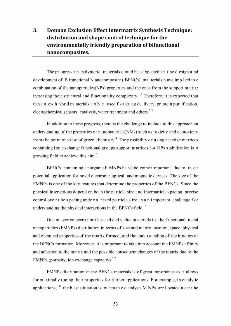
3. Donnan Exclusion Effect Intermatrix Synthesis Technique:distribution and shape control technique for theenvironmentally friendly preparation of bifunctionalnanocomposites.
The pr ogress i n polymeric materials c ould be e xpected i n t he d esign a nd
development of B ifunctional N anocomposite ( BFNCs) ma terials h ave imp lied th e
combination of the nanoparticles(NPs) properties and the ones from the support matrix;
increasing their structural and functionality complexity.1,2 Therefore, it is expected that
these n ew h ybrid m aterials t o b e used f or dr ug de livery, pr otein pur ification,
electrochemical sensors, catalysis, water treatment and others.2,3
In addition to these progress, there is the challenge to include to this approach an
understanding of the properties of nanomaterials(NMs) such as toxicity and ecotoxicity
from the point of view of green chemistry.4 The possibility of using reactive matrices
containing i on e xchange f unctional gr oups s upport m atrices f or N Ps s tabilization is a
growing field to achieve this aim.5
BFNCs containing i norganic F MNPs ha ve be come i mportant due to th eir
potential application for novel electronic, optical, and magnetic devices. The size of the
FMNPs is one of the key features that determine the properties of the BFNCs. Since the
physical interactions depend on bot h the particle size and interparticle spacing, precise
control ove r t he s pacing unde r a f ixed pa rticle s ize i s a n i mportant challenge f or
understanding the physical interactions in the BFNCs field. 6
One m ayor co ncern f or t hese ad ded v alue m aterials i s t he f unctional metal
nanoparticles (FMNPs) distribution in terms of size and matrix location, space, physical
and chemical properties of the matrix formed, and the understanding of the kinetics of
the BFNCs formation. Moreover, it is important to take into account the FMNPs affinity
and adhesion to the matrix and the possible consequent changes of the matrix due to the
FMNPs (porosity, ion exchange capacity) 2,7
FMNPs distribution in the BFNCs materials is of great importance as it allows
for maximally tuning their properties for further applications. For example, in catalytic
applications, 8 the b est s ituation is w hen th e c atalysts M NPs are l ocated n ear t he
53
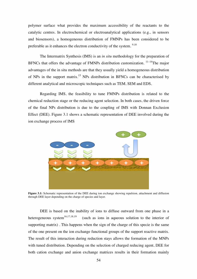
polymer surface what provides the maximum accessibility of the reactants to the
catalytic centres. In electrochemical or electroanalytical applications (e.g., in sensors
and biosensors), a homogeneous distribution of FMNPs has been considered to be
preferable as it enhances the electron conductivity of the system. 9,10
The Intermatrix Synthesis (IMS) is an in situ methodology for the preparation of
BFNCs that offers the advantage of FMNPs distribution customization. 11–14The major
advantages of the in situ methods are that they usually yield a homogeneous distribution
of NPs in the support matrix.15 NPs distribution in BFNCs can be characterised by
different analytical and microscopic techniques such as TEM, SEM and EDS,
Regarding IMS, the feasibility to tune FMNPs distribution is related to the
chemical reduction stage or the reducing agent selection. In both cases, the driven force
of the final NPs distribution is due to the coupling of IMS with Donnan Exclusion
Effect (DEE). Figure 3.1 shows a schematic representation of DEE involved during the
ion exchange process of IMS
Figure 3.1: Schematic representation of the DEE during ion exchange showing repulsion, attachment and diffusion through DEE layer depending on the charge of species and layer.
DEE is based on the inability of ions to diffuse outward from one phase in a
heterogeneous system16,17,18,19 (such as ions in aqueous solution to the interior of
supporting matrix) . This happens when the sign of the charge of this specie is the same
of the one present on the ion exchange functional groups of the support reactive matrix.
The result of this interaction during reduction stays allows the formation of the MNPs
with tuned distribution. Depending on the selection of charged reducing agent, DEE for
both cation exchange and anion exchange matrices results in their formation mainly
+ ++++ ++
-- -
++
54
near the surface of the polymer. If a neutral reducing agent is chosen, the NPs
distribution in the BFNCs is distributed in the interior and exterior zone of the matrix;
as shown in Figure 3.2.
Figure 3.2: Schematic representation of FMNPs distribution due to IMS A) Raw ion exchanger surface B) FMNPs with favourable distribution mainly on the ion exchanger surface because of DEE interaction with metal precursors and reducing agents and C) FMNPs distribution
This chapter evaluates and proves the DEE coupled with the IMS (DEEIMS) on
the FMNPs distribution and the role of reducing agent on the preparation of different
NMs.
3.1 Preparation of CdS-QDs on cationic gel type polymeric matrix
by DEEIMS-precipitation technique.
QDs are special kind of nanomaterials because of optical and semi-conducting
properties.20–23 Specifically, CdS-QDs are feasible NMs to be prepared by DEEIMS-
precipitation technique. This method is inexpensive, versatile, and technologically
simple to produce different kind of NPs as well as BFNCs of a wide range of materials
such as metal oxide NPs and QDs.24,25,26 The synthetic procedure requires the control
over reaction conditions: pH, temperature and NPs - precursors.
As every NPs synthetic route, it lies in control of the particle size and thus
achieving a narrow particle size and special distribution. Regarding this fact, DEEIMS
becomes a valid methodology for the preparation, for example, of CdS-QDs containing
BFNCs with favourable distribution on a gel-type cationic polymeric matrix. In
addition, the in situ preparation gives an extra level of stability to of these QDs –
BFNCs.
A B C
55
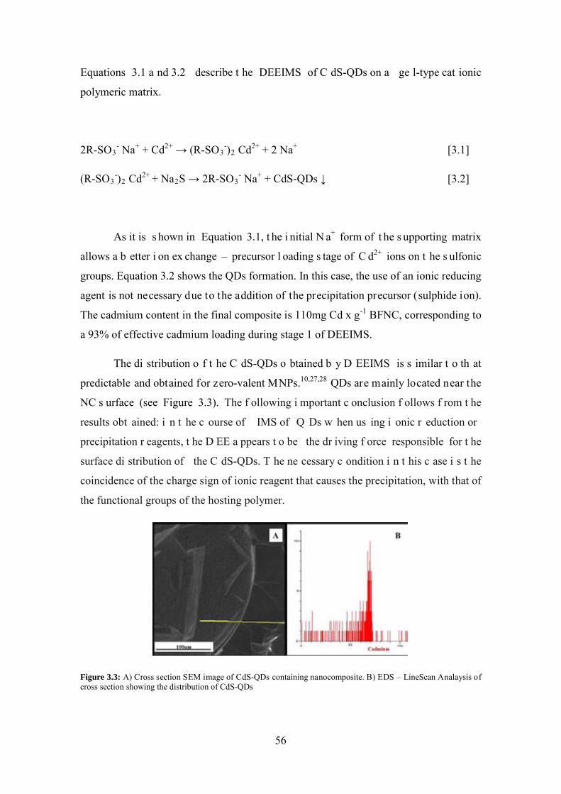
Equations 3.1 a nd 3.2 describe t he DEEIMS of C dS-QDs on a ge l-type cat ionic
polymeric matrix.
2R-SO3- Na+ + Cd2+ → (R-SO3
-)2 Cd2+ + 2 Na+ [3.1]
(R-SO3-)2 Cd2+ + Na2S → 2R-SO3
- Na+ + CdS-QDs ↓ [3.2]
As it is s hown in Equation 3.1, t he i nitial N a+ form of t he s upporting matrix
allows a b etter i on ex change – precursor l oading s tage of C d2+ ions on t he s ulfonic
groups. Equation 3.2 shows the QDs formation. In this case, the use of an ionic reducing
agent is not necessary due to the addition of the precipitation precursor (sulphide ion).
The cadmium content in the final composite is 110mg Cd x g-1 BFNC, corresponding to
a 93% of effective cadmium loading during stage 1 of DEEIMS.
The di stribution o f t he C dS-QDs o btained b y D EEIMS is s imilar t o th at
predictable and obtained for zero-valent MNPs.10,27,28 QDs are mainly located near the
NC s urface (see Figure 3.3). The f ollowing i mportant c onclusion f ollows f rom t he
results obt ained: i n t he c ourse of IMS of Q Ds w hen us ing i onic r eduction or
precipitation r eagents, t he D EE a ppears t o be the dr iving f orce responsible for t he
surface di stribution of the C dS-QDs. T he ne cessary c ondition i n t his c ase i s t he
coincidence of the charge sign of ionic reagent that causes the precipitation, with that of
the functional groups of the hosting polymer.
Figure 3.3: A) Cross section SEM image of CdS-QDs containing nanocomposite. B) EDS – LineScan Analaysis of cross section showing the distribution of CdS-QDs
56
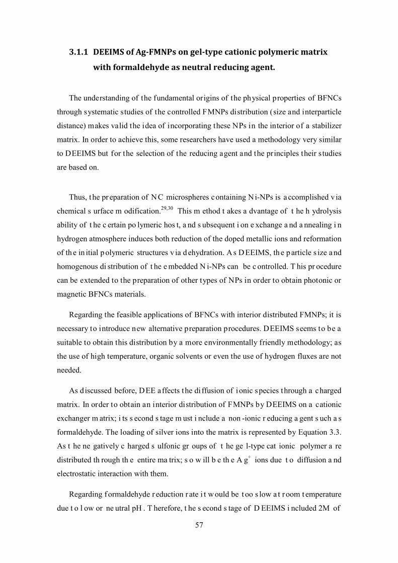
3.1.1 DEEIMS of Ag-FMNPs on gel-type cationic polymeric matrix
with formaldehyde as neutral reducing agent.
The understanding of the fundamental origins of the physical properties of BFNCs
through systematic studies of the controlled FMNPs distribution (size and interparticle
distance) makes valid the idea of incorporating these NPs in the interior of a stabilizer
matrix. In order to achieve this, some researchers have used a methodology very similar
to DEEIMS but for the selection of the reducing agent and the principles their studies
are based on.
Thus, t he pr eparation of NC microspheres containing Ni-NPs is a ccomplished v ia
chemical s urface m odification.29,30 This m ethod t akes a dvantage of t he h ydrolysis
ability of t he c ertain po lymeric hos t, a nd s ubsequent i on e xchange a nd a nnealing i n
hydrogen atmosphere induces both reduction of the doped metallic ions and reformation
of th e in itial p olymeric structures v ia d ehydration. A s D EEIMS, th e p article s ize and
homogenous di stribution of t he e mbedded N i-NPs can be c ontrolled. T his pr ocedure
can be extended to the preparation of other types of NPs in order to obtain photonic or
magnetic BFNCs materials.
Regarding the feasible applications of BFNCs with interior distributed FMNPs; it is
necessary to introduce new alternative preparation procedures. DEEIMS seems to be a
suitable to obtain this distribution by a more environmentally friendly methodology; as
the use of high temperature, organic solvents or even the use of hydrogen fluxes are not
needed.
As d iscussed before, DEE affects the di ffusion of ionic species through a charged
matrix. In order to obtain an interior distribution of FMNPs by DEEIMS on a cationic
exchanger m atrix; i ts s econd s tage m ust i nclude a non -ionic r educing a gent s uch a s
formaldehyde. The loading of silver ions into the matrix is represented by Equation 3.3.
As t he ne gatively c harged s ulfonic gr oups of t he ge l-type cat ionic polymer a re
distributed th rough th e entire ma trix; s o w ill b e th e A g+ ions due t o diffusion a nd
electrostatic interaction with them.
Regarding f ormaldehyde r eduction r ate i t w ould be t oo s low a t r oom t emperature
due t o l ow or ne utral pH . T herefore, t he s econd s tage of D EEIMS i ncluded 2M of
57
formaldehyde i n a queous a lkaline s olution. T hese c onditions m ake f ormaldehyde a
suitable reducing agent for silver.31,32
DEEIMS o f Ag -FMNPs on a gel-type c ationic polymeric r esin us ing
formaldehyde as neutral reducing agent is presented in equiations 3.3 and 3.4
R-SO3- Na+ + Ag+ → R-SO3
- Ag+ + Na+ [3.3]
2R-SO3- Ag+ + CH2O + H2O → 2R-SO3
- Na+ HCOO- +3 H+ + 2Ag0 [3.4]
Equation 3.3 shows the typical DEEIMS NPs – precursor loading stage, in this
case of s ilver i ons due to t he e xchange of N a+ to Ag +. C onsequently, Equation 3.4
presents the formation of Ag-FMNPs. The silver content in the final BFNCs was around
159mg Ag x g -1 BFNC, which corresponds to 70% efficiency of silver loading during
DEEIMS stage 1.
In order to confirm the Ag-NPs intern distribution in the gel-type polymer, SEM
characterization and EDS analysis were performed to the samples. As it can be seen in
Figure 3.4, the element mapping and the LineScan EDS analysis verify this. Moreover,
distribution is consistent and conclusive of DEE influence during the appearance of the
FMNPs in the second stage of DEEIMS.
Figure 3.4: A) C ross s ection o f Ag -FMNPs c ontaining na nocomposite with B ) E lement M apping a nd C ) E DS -LineScan analysis showing the interior distribution of Ag-FMNPs due to IMS with formaldehyde as reducing agent
58
3.2 DEEIMS of Au and Ag-FMNPs on gel-type anionic polymer using ascorbic acid (AA) and sodium borohydride (NaBH4) as ionic reducing agents.
The de volopment of D EEIMS i n our r esearch gr oup ha s be en done mostly on
catiionic p olymeric ex changers.11,12,25,33–35 Nevertheless, a s one o f t he principles of
DEEIMS is the feasibility to load the FMNPs precursors by an ion exchange stage to a
suitable f orm of t he e xchanger s upport; t his t echnique i s a s uitable f or t he s urface
modfication of anionic exchanger matrices with FMNPs.10,25
As it has been shown in reactions 3.1 a nd 3.3; usually the initail stage of DEEIMS
involves the loading of the metal ion (NPs precursor) to the cationic exchanger matrix.
As for anionic exchangers, DEE disables the di ffusion of cations through this t ype of
matrices. Therefore; two DEEIMS alternative procedures could be carried out. The first
one consists in a symmetrical version of DEEIMS for cationic exchangers, in which the
first s tage i s t he l oading of t he i onic r educing a gent ( usually anions) a nd c onsequent
loading of t he m etal c ation ( NPs pr ecursor) a t t he r eductions s tage. T he s econd
procedure consists in the use of an anionic NPs – precursor (such as HAuCl4) followed
by the reducing stage.
3.2.1 Symmetrical version of classical DEEIMS applied for anionic matrices.
Thus, r egarding t he s ymmetrical D EEIMS pr ocedure for a nionic exchangers; t he
first stage would consist in the loading of an anionic reducing agent as NaBH4. Then,
from a m ore f avourable i onic form f or a nionic e xchange ( Cl--form), t he s tages f or
DEEIMS of Ag-FMNPs are presented as follows in Equations 3.5 and 3.6
R-(R4-N)+Cl- + NaBH4 → R-(R4-N)+BH4- + NaCl [3.5]
R-(R4-N)+BH4- + AgNO3 + 3H2O → R-(R4-N)+NO3
- +Ag0 + 7/2 H2 + B(OH)3 [3.6]
59

The negative charge present in BH4- makes i t to get at tached to the quaternary
amine groups of the support matrix due to DEE. The opposite effect occurs to the silver
ions which bear positive charge and it results that the reduction process appears to be
“localized” mainly near t he s urface o f t his p olymer. The A g-NPs di stribution c an be
observed in Figures 3.6A and 3.6B. Moreover the Ag content for the BFNCs prepared
by t his m ethodology c orresponds t o a n a verage 180m g A g x g -1 BFNC for a m etal
loading efficiency of 77%.
As it can be seen in Equation 3.6, the oxidation of BH4- ion leads to the release
of hydrogen. As discussed before, hydrogen has been used as neutral reducing agent for
the pr eparation of BFNCs with in ternal d istribution o f N i mic rostructures.29,30 Thus,
ascorbic acid (C6H8O6 = AA) was used as neutral reducing agent for DEEIMS of Ag-
FMNPs.to ve rify t hat the r eduction of Ag ions, a nd c onsequently t he A g-NPs
distribution in this NC, is due to the DEE for BH4- and not because of the release of H.
Considering [AA]ox= C6H6O6, the oxidation of AA is presented in Equation 3.7 and the
reduction of Ag+ ions with AA is presented in Equation 3.8. Chemical structures of AA
and [AA]ox are presented in Figure 3.5.
C6H8O6 → C6H6O6 + 2e- + 2H+ [3.7]
[R-(R4-N)+Cl-]2 AA + 2AgNO3 → 2R-(R4-N)+NO3- +Ag0 - +2Cl- + [AA]ox [3.8]
AA is u sed as t he r educing ag ent b ecause i t i s weaker t han N aBH4, a nd a lso
because the reducing ability of ascorbic acid can be easily tuned through adjustment of
the solution pH.36 For our purposes, it is a suitable redox agent for silver ions with no
associated release of H2 (see Equation 3.7). The Ag-NPs distribution can be observed in
Figure 3.5 Schematic representation of chemical structures AA and [AA]ox
60
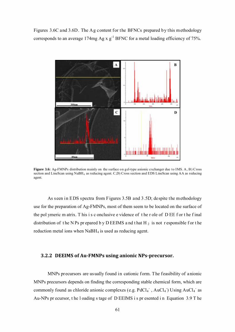
Figures 3.6C and 3.6D. The Ag content for the BFNCs prepared by this methodology
corresponds to an average 174mg Ag x g-1 BFNC for a metal loading efficiency of 75%.
Figure 3.6: Ag-FMNPs distribution mainly on the surface on gel-type anionic exchanger due to IMS. A, B) Cross section and LineScan using NaBH4 as reducing agent. C,D) Cross section and EDS LineScan using AA as reducing agent.
As seen in EDS spectra from Figures 3.5B and 3 .5D; despite the methodology
use for the preparation of Ag-FMNPs, most of them seem to be located on the surface of
the pol ymeric m atrix. T his i s c onclusive e vidence of t he r ole of D EE f or t he f inal
distribution of t he N Ps pr epared b y D EEIMS a nd t hat H 2 is not r esponsible f or t he
reduction metal ions when NaBH4 is used as reducing agent.
3.2.2 DEEIMS of Au-FMNPs using anionic NPs-precursor.
MNPs precursors are usually found in cationic form. The feasibility of anionic
MNPs precursors depends on finding the corresponding stable chemical form, which are
commonly found as chloride anionic complexes (e.g. PdCl4- , AuCl4
-) Using AuCl4- as
Au-NPs pr ecursor, t he l oading s tage of D EEIMS i s pr esented i n Equation 3.9 T he
61
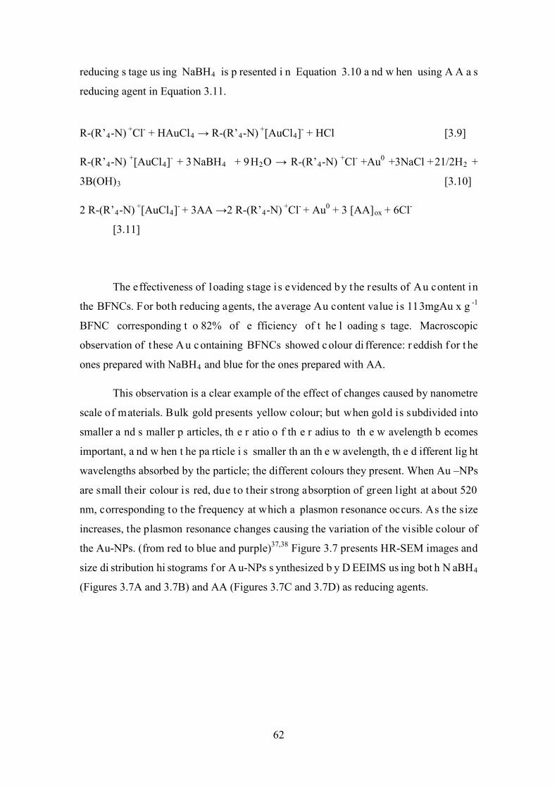
reducing s tage us ing NaBH4 is p resented i n Equation 3.10 a nd w hen using A A a s
reducing agent in Equation 3.11.
R-(R’4-N) +Cl- + HAuCl4 → R-(R’4-N) +[AuCl4]- + HCl [3.9]
R-(R’4-N) +[AuCl4]- + 3NaBH4 + 9H2O → R-(R’4-N) +Cl- +Au0 +3NaCl +21/2H2 +
3B(OH)3 [3.10]
2 R-(R’4-N) +[AuCl4]- + 3AA →2 R-(R’4-N) +Cl- + Au0 + 3 [AA]ox + 6Cl-
[3.11]
The effectiveness of loading s tage is evidenced by the results of Au content in
the BFNCs. For both reducing agents, the average Au content value is 113mgAu x g -1
BFNC corresponding t o 82% of e fficiency of t he l oading s tage. Macroscopic
observation of t hese A u c ontaining BFNCs showed c olour di fference: r eddish f or t he
ones prepared with NaBH4 and blue for the ones prepared with AA.
This observation is a clear example of the effect of changes caused by nanometre
scale of materials. Bulk gold presents yellow colour; but when gold is subdivided into
smaller a nd s maller p articles, th e r atio o f th e r adius to th e w avelength b ecomes
important, a nd w hen t he pa rticle i s smaller th an th e w avelength, th e d ifferent lig ht
wavelengths absorbed by the particle; the different colours they present. When Au –NPs
are small their colour is red, due to their strong absorption of green light at about 520
nm, corresponding to the frequency at which a plasmon resonance occurs. As the size
increases, the plasmon resonance changes causing the variation of the visible colour of
the Au-NPs. (from red to blue and purple)37,38 Figure 3.7 presents HR-SEM images and
size di stribution hi stograms f or A u-NPs s ynthesized b y D EEIMS us ing bot h N aBH4
(Figures 3.7A and 3.7B) and AA (Figures 3.7C and 3.7D) as reducing agents.
62
Figure 3.7: HR-SEM image and size distribution histogram of Au FMNPs on anionic gel – type polymer A, B) IMS using NaBH4 as reducing agent. C,D) IMS using AA as reducing agent. Non evidence of agglomeration is observed in neither case.
The s ize di stribution hi stograms s how t hat A u-NPs s ynthesized w ith N aBH4
have an av erage d iameter o f 12.0 ± 0.8 nm ; meanwhile t he Au-NPs s ynthesized with
AA h ave an av erage d iameter o f 79 ± 3nm. This s izes ex plain t he difference o f
macroscopic colour of the Au-NPs containing BFNCs.
The s ize d ifference b etween al ternative r outes o f D EEIMS d epends o n t he
strength of t he reducing a gent used i n t he N Ps f ormation s tage, s ummed t o t he
stabilization offered by the supporting matrix. A strong reducing agent ensures that the
particles obtained are s maller and monodisperse t han the ones obt ained when us ing a
weaker reducing agent.36 The reduction rate of NaBH4 is so much faster than the one
from AA. That faster rate produces a large number of NPs and may inhibit aggregation
mechanisms ( this a dded to th e s tability o ffered b y p olymeric ma trix). In o rder t o
produce larger particles, the number of NPs nuclei should be low; thus the NPs grow is
related at the expense of the remaining metal ions in solutions that could be reduced.39,40
63
3.3 DEEIMS of Ag-FMNPs on gel-type cationic polymer using AA and NaBH4 as reducing agents.
As discused before, DEEIMS for cationic exchangers is based on the initial loading
stage o f cat ionic MNPs pecursors (Equation 3.3), followed by the use of a negatively
charged r educing a gent during t he s econd s tage. T hus, t he r educing a gent be ars t he
same charge of the functional groups of the cationic exchanger (e.g. sulfonic).
The bor ohydride a nions a lso be ar ne gative c harges a nd t herefore, c annot de eply
penetrate inside the matrix due to the action of electrostatic repulsion (DEE). The depth
of their penetration inside the matrix is balanced by the sum of two driving forces acting
in t he oppos ite d irections: 1) t he gr adient of borohydride c oncentration a nd 2) t he
DEE 19 The a ction of t he s econd f orce l imits de ep pe netration of bor ohydride a nions
into the matrix so that Equation 3.12 proceeds in the surface zone of the polymer what
results in the formation of MNPs mainly near th e surface o f the matrix. The Ag-NPs
distribution obtained by this synthetic route is shown in Figures 3.8A and 3.8B. The Ag
content obtained by this procedure is 200mg Ag x g -1 BFNC corresponding to 88% of
effective loading stage.
R-SO3−Ag+ + NaBH4 + 3H2O → R-SO3
−Na+ + 7/2H2 + B(OH)3 + Ag0 [3.12]
Consequently with the results obtained for anionic DEEIMS with NaBH4 ; the
effective role of the reduction due to BH4- and not because of the released H2 should be
proved. Therefore t he second stage of DEEIMS was carried out using AA as reducing
agent a s s hown i n Equation 3.13. F igures 3. 8C a nd 3.8D pr esent t he A g-NPs
distribution obtained by this methodology. Moreover, the Ag content obtained by this
route is 190 mg Ag x g-1 BFNC for 84% of effective loading stage.
2[R-SO3−Ag+ ] + AA +H3O+ → 2[R-SO3
−H+] + [AA]ox + Ag0 + H2O [3.13]
64
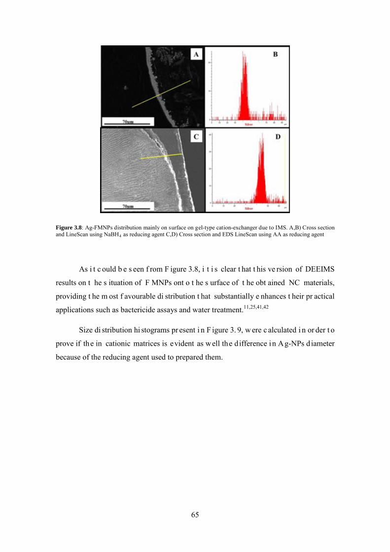
Figure 3.8: Ag-FMNPs distribution mainly on surface on gel-type cation-exchanger due to IMS. A,B) Cross section and LineScan using NaBH4 as reducing agent C,D) Cross section and EDS LineScan using AA as reducing agent
As i t c ould b e s een f rom F igure 3.8, i t i s clear t hat t his ve rsion of DEEIMS
results on t he s ituation of F MNPs ont o t he s urface of t he obt ained NC materials,
providing t he m ost f avourable di stribution t hat substantially e nhances t heir pr actical
applications such as bactericide assays and water treatment.11,25,41,42
Size di stribution hi stograms pr esent i n F igure 3. 9, w ere c alculated i n or der t o
prove if the in cationic matrices is evident as well the d ifference in Ag-NPs d iameter
because of the reducing agent used to prepared them.
65
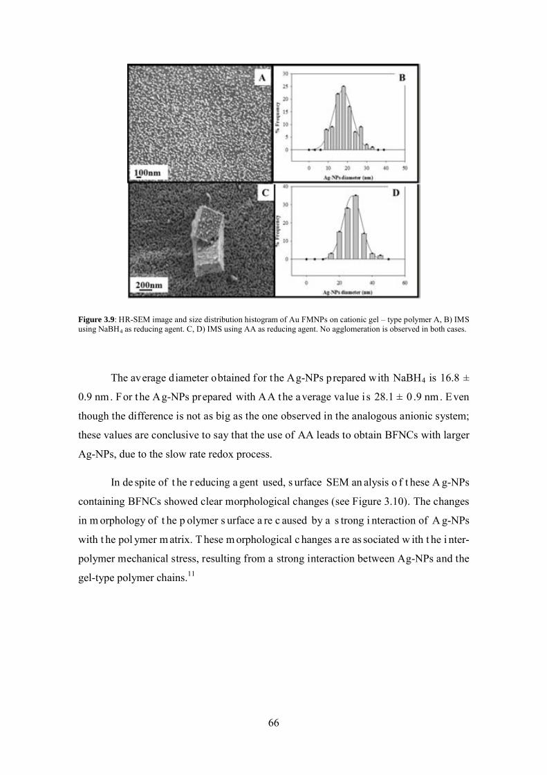
Figure 3.9: HR-SEM image and size distribution histogram of Au FMNPs on cationic gel – type polymer A, B) IMS using NaBH4 as reducing agent. C, D) IMS using AA as reducing agent. No agglomeration is observed in both cases.
The average diameter obtained for the Ag-NPs prepared with NaBH4 is 16.8 ±
0.9 nm. For the Ag-NPs prepared with AA the average value i s 28.1 ± 0 .9 nm. Even
though the difference is not as big as the one observed in the analogous anionic system;
these values are conclusive to say that the use of AA leads to obtain BFNCs with larger
Ag-NPs, due to the slow rate redox process.
In de spite of t he r educing a gent used, s urface SEM an alysis o f t hese A g-NPs
containing BFNCs showed clear morphological changes (see Figure 3.10). The changes
in m orphology of t he p olymer s urface a re c aused by a s trong i nteraction of A g-NPs
with t he pol ymer m atrix. T hese m orphological c hanges a re as sociated w ith t he i nter-
polymer mechanical stress, resulting from a strong interaction between Ag-NPs and the
gel-type polymer chains.11
66
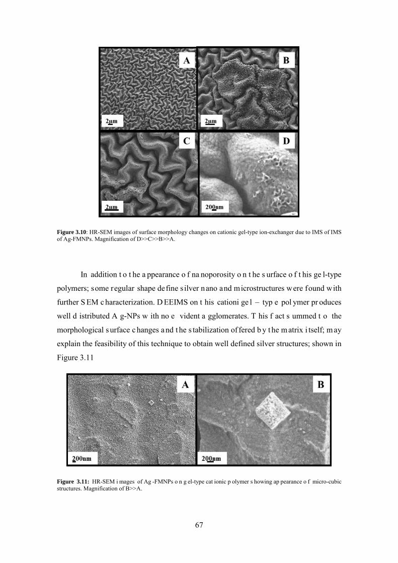
Figure 3.10: HR-SEM images of surface morphology changes on cationic gel-type ion-exchanger due to IMS of IMS of Ag-FMNPs. Magnification of D>>C>>B>>A.
In addition t o t he a ppearance o f na noporosity o n t he s urface o f t his ge l-type
polymers; some regular shape define s ilver nano and microstructures were found with
further S EM c haracterization. D EEIMS on t his cationi ge l – typ e pol ymer pr oduces
well d istributed A g-NPs w ith no e vident a gglomerates. T his f act s ummed t o the
morphological s urface c hanges a nd t he s tabilization of fered b y t he m atrix i tself; m ay
explain the feasibility of this technique to obtain well defined silver structures; shown in
Figure 3.11
Figure 3.11: HR-SEM i mages of Ag -FMNPs o n g el-type cat ionic p olymer s howing ap pearance o f micro-cubic structures. Magnification of B>>A.
67
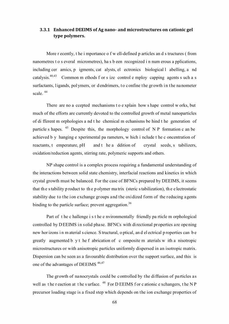
3.3.1 Enhanced DEEIMS of Ag nano- and microstructures on cationic gel type polymers.
More r ecently, t he i mportance o f w ell-defined p articles an d s tructures ( from
nanometres t o s everal micrometres), ha s b een recognized i n num erous a pplications,
including cer amics, p igments, cat alysts, el ectronics biological l abelling, a nd
catalysis.40,43 Common m ethods f or s ize control e mploy capping agents s uch a s
surfactants, l igands, pol ymers, or d endrimers, t o confine t he growth in t he nanometer
scale. 44
There are no a ccepted mechanisms t o e xplain how s hape control w orks, but
much of the efforts are currently devoted to the controlled growth of metal nanoparticles
of di fferent m orphologies a nd t he chemical m echanisms be hind t he generation of
particle s hapes. 45 Despite this, the morphology control of N P formation c an be
achieved b y hanging e xperimental pa rameters, w hich i nclude t he c oncentration of
reactants, t emperature, pH and t he a ddition of crystal seeds, s tabilizers,
oxidation/reduction agents, stirring rate, polymeric supports and others.
NP shape control is a complex process requiring a fundamental understanding of
the interactions between solid state chemistry, interfacial reactions and kinetics in which
crystal growth must be balanced. For the case of BFNCs prepared by DEEIMS, it seems
that th e s tability p roduct to th e p olymer ma trix (steric s tabilization), th e e lectrostatic
stability due to the ion exchange groups and the oxidized form of the reducing agents
binding to the particle surface; prevent aggregation.36
Part of t he c hallenge i s t he e nvironmentally friendly pa rticle m orphological
controlled by D EEIMS in solid phase. BFNCs with di rectional properties are opening
new hor izons i n m aterial s cience. S tructural, o ptical, an d el ectrical p roperties can b e
greatly augmented b y t he f abrication of c omposite m aterials w ith a nisotropic
microstructures or with anisotropic particles uniformly dispersed in an isotropic matrix.
Dispersion can be seen as a favourable distribution over the support surface, and this is
one of the advantages of DEEIMS 46,47
The growth of nanocrystals could be controlled by the diffusion of particles as
well as t he r eaction at t he s urface. 48 For D EEIMS f or c ationic e xchangers, t he N P
precursor loading stage is a fixed step which depends on the ion exchange properties of
68
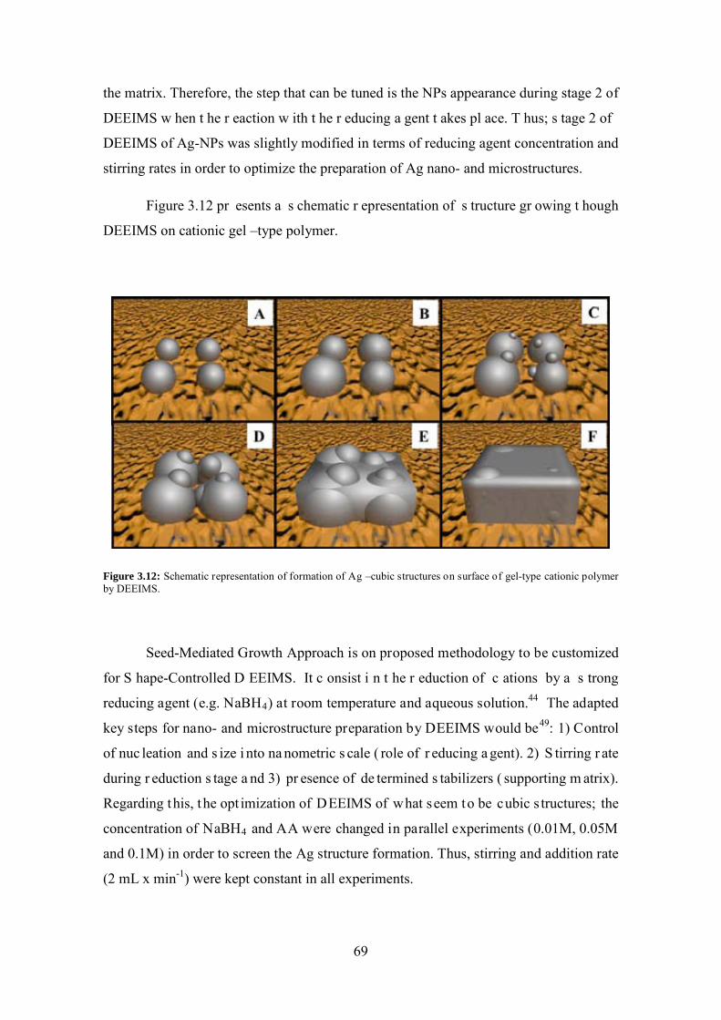
the matrix. Therefore, the step that can be tuned is the NPs appearance during stage 2 of
DEEIMS w hen t he r eaction w ith t he r educing a gent t akes pl ace. T hus; s tage 2 of
DEEIMS of Ag-NPs was slightly modified in terms of reducing agent concentration and
stirring rates in order to optimize the preparation of Ag nano- and microstructures.
Figure 3.12 pr esents a s chematic r epresentation of s tructure gr owing t hough
DEEIMS on cationic gel –type polymer.
Figure 3.12: Schematic representation of formation of Ag –cubic structures on surface of gel-type cationic polymer by DEEIMS.
Seed-Mediated Growth Approach is on proposed methodology to be customized
for S hape-Controlled D EEIMS. It c onsist i n t he r eduction of c ations by a s trong
reducing agent (e.g. NaBH4) at room temperature and aqueous solution.44 The adapted
key steps for nano- and microstructure preparation by DEEIMS would be49: 1) Control
of nuc leation and s ize i nto na nometric s cale ( role of r educing a gent). 2) S tirring r ate
during r eduction s tage a nd 3) pr esence of de termined s tabilizers ( supporting m atrix).
Regarding this, the opt imization of DEEIMS of what seem to be cubic s tructures; the
concentration of NaBH4 and AA were changed in parallel experiments (0.01M, 0.05M
and 0.1M) in order to screen the Ag structure formation. Thus, stirring and addition rate
(2 mL x min-1) were kept constant in all experiments.
69
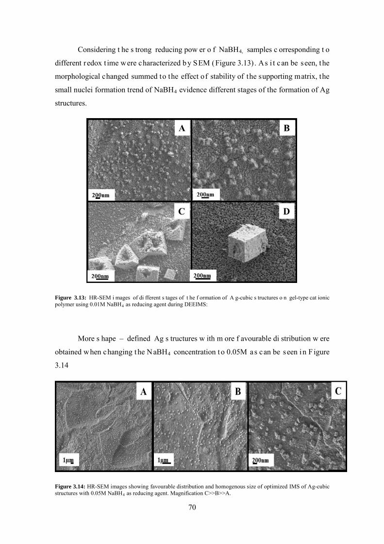
Considering t he s trong reducing pow er o f NaBH4, samples c orresponding t o
different redox t ime were characterized b y SEM (Figure 3.13) . As i t can be seen, the
morphological changed summed to the effect of stability of the supporting matrix, the
small nuclei formation trend of NaBH4 evidence different stages of the formation of Ag
structures.
Figure 3.13: HR-SEM i mages of di fferent s tages of t he f ormation of A g-cubic s tructures o n gel-type cat ionic polymer using 0.01M NaBH4 as reducing agent during DEEIMS:
More s hape – defined Ag s tructures w ith m ore f avourable di stribution w ere
obtained when changing the NaBH4 concentration to 0.05M as can be seen in F igure
3.14
Figure 3.14: HR-SEM images showing favourable distribution and homogenous size of optimized IMS of Ag-cubic structures with 0.05M NaBH4 as reducing agent. Magnification C>>B>>A.
70
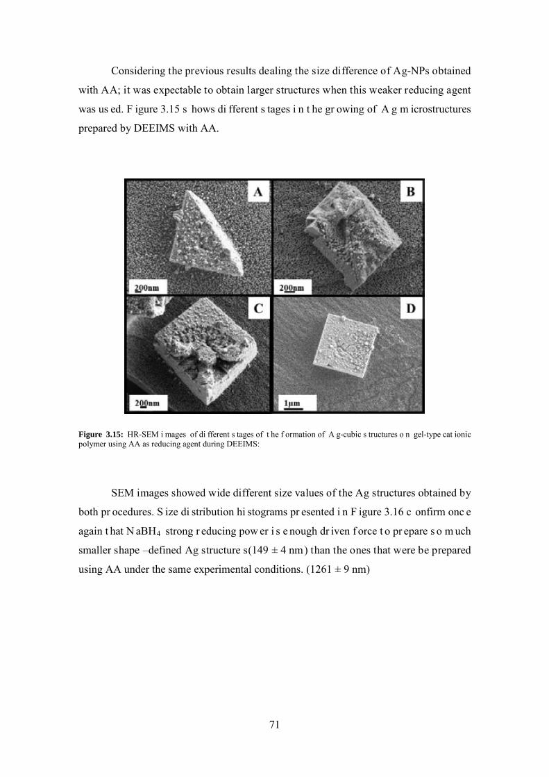
Considering the previous results dealing the size difference of Ag-NPs obtained
with AA; it was expectable to obtain larger structures when this weaker reducing agent
was us ed. F igure 3.15 s hows di fferent s tages i n t he gr owing of A g m icrostructures
prepared by DEEIMS with AA.
Figure 3.15: HR-SEM i mages of di fferent s tages of t he f ormation of A g-cubic s tructures o n gel-type cat ionic polymer using AA as reducing agent during DEEIMS:
SEM images showed wide different size values of the Ag structures obtained by
both pr ocedures. S ize di stribution hi stograms pr esented i n F igure 3.16 c onfirm onc e
again t hat N aBH4 strong r educing pow er i s e nough dr iven f orce t o pr epare s o m uch
smaller shape –defined Ag structure s(149 ± 4 nm) than the ones that were be prepared
using AA under the same experimental conditions. (1261 ± 9 nm)
71
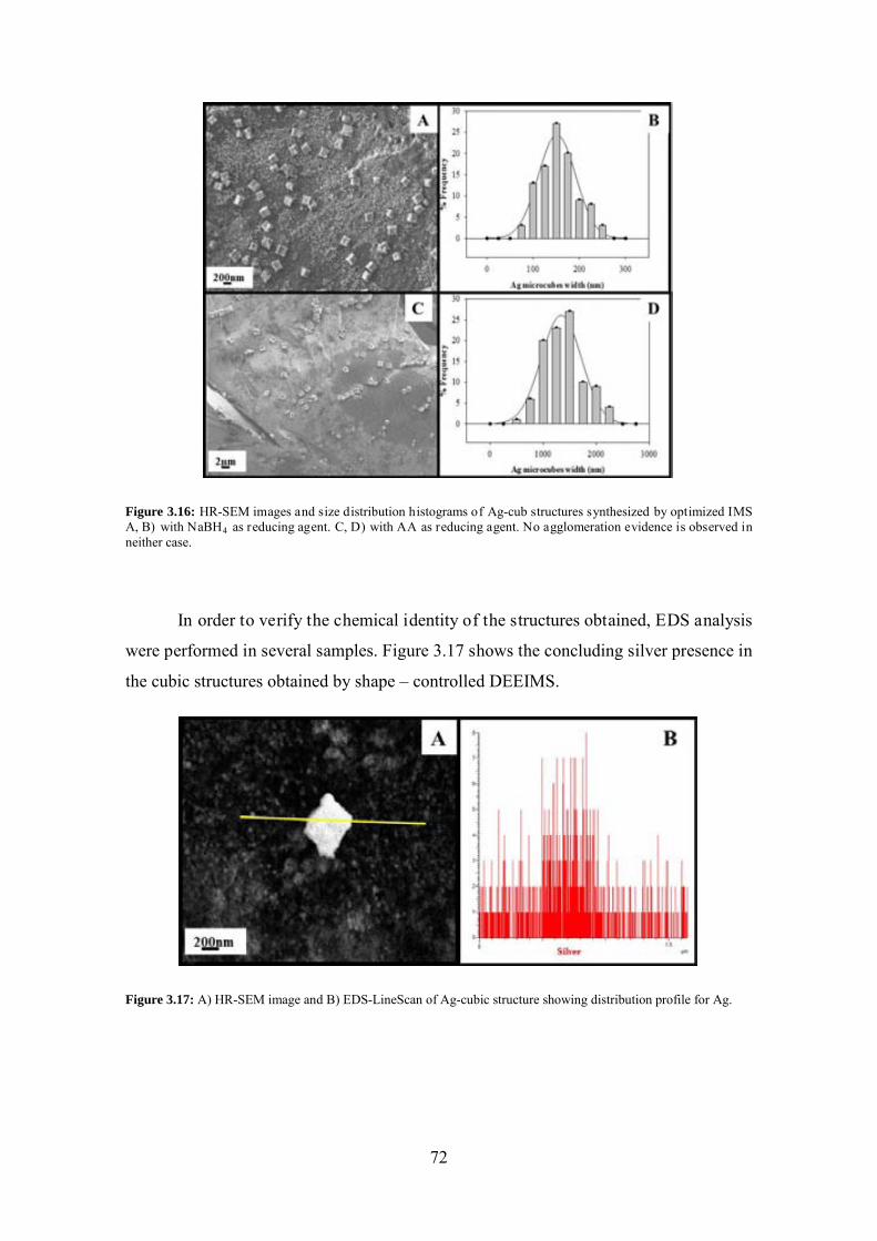
Figure 3.16: HR-SEM images and size distribution histograms of Ag-cub structures synthesized by optimized IMS A, B) with NaBH4 as reducing agent. C, D) with AA as reducing agent. No agglomeration evidence is observed in neither case.
In order to verify the chemical identity of the structures obtained, EDS analysis
were performed in several samples. Figure 3.17 shows the concluding silver presence in
the cubic structures obtained by shape – controlled DEEIMS.
Figure 3.17: A) HR-SEM image and B) EDS-LineScan of Ag-cubic structure showing distribution profile for Ag.
72
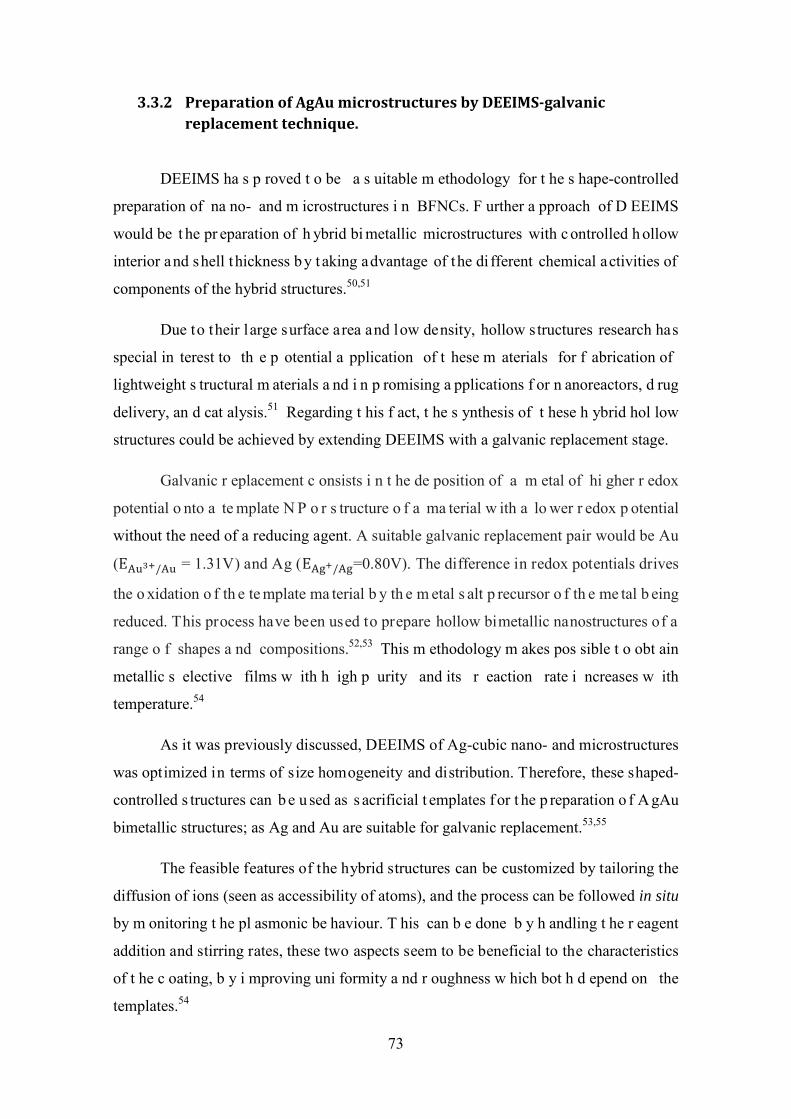
3.3.2 Preparation of AgAu microstructures by DEEIMS-galvanic replacement technique.
DEEIMS ha s p roved t o be a s uitable m ethodology for t he s hape-controlled
preparation of na no- and m icrostructures i n BFNCs. F urther a pproach of D EEIMS
would be t he pr eparation of h ybrid bi metallic microstructures with c ontrolled h ollow
interior and shell thickness by t aking advantage of the di fferent chemical activities of
components of the hybrid structures.50,51
Due to their large surface area and low density, hollow structures research has
special in terest to th e p otential a pplication of t hese m aterials for f abrication of
lightweight s tructural m aterials a nd i n p romising a pplications f or n anoreactors, d rug
delivery, an d cat alysis.51 Regarding t his f act, t he s ynthesis of t hese h ybrid hol low
structures could be achieved by extending DEEIMS with a galvanic replacement stage.
Galvanic r eplacement c onsists i n t he de position of a m etal of hi gher r edox
potential o nto a te mplate N P o r s tructure o f a ma terial w ith a lo wer r edox p otential
without the need of a reducing agent. A suitable galvanic replacement pair would be Au
(EAu3+/Au = 1.31V) and Ag (EAg+/Ag=0.80V). The difference in redox potentials drives
the o xidation o f th e te mplate ma terial b y th e m etal s alt p recursor o f th e me tal b eing
reduced. This process have been used to prepare hollow bimetallic nanostructures of a
range o f shapes a nd compositions.52,53 This m ethodology m akes pos sible t o obt ain
metallic s elective films w ith h igh p urity and its r eaction rate i ncreases w ith
temperature.54
As it was previously discussed, DEEIMS of Ag-cubic nano- and microstructures
was optimized in terms of size homogeneity and distribution. Therefore, these shaped-
controlled s tructures can b e u sed as s acrificial t emplates f or t he p reparation o f A gAu
bimetallic structures; as Ag and Au are suitable for galvanic replacement.53,55
The feasible features of the hybrid structures can be customized by tailoring the
diffusion of ions (seen as accessibility of atoms), and the process can be followed in situ
by m onitoring t he pl asmonic be haviour. T his can b e done b y h andling t he r eagent
addition and stirring rates, these two aspects seem to be beneficial to the characteristics
of t he c oating, b y i mproving uni formity a nd r oughness w hich bot h d epend on the
templates.54
73
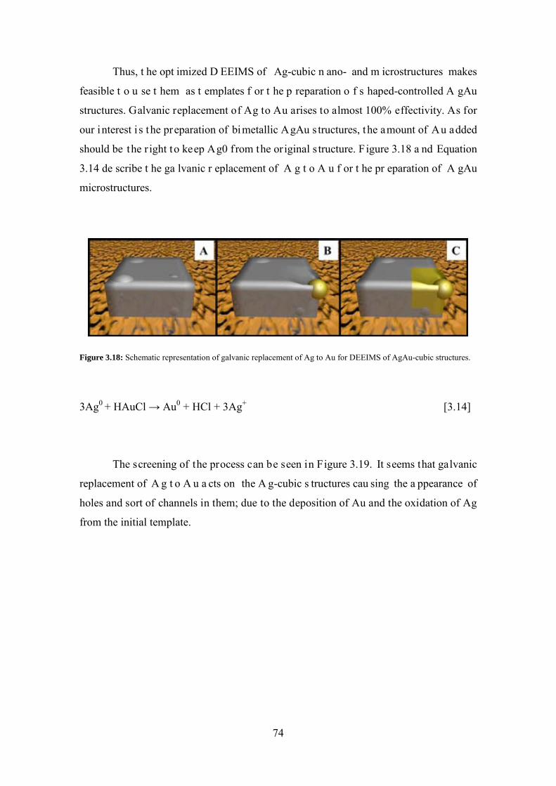
Thus, t he opt imized D EEIMS of Ag-cubic n ano- and m icrostructures makes
feasible t o u se t hem as t emplates f or t he p reparation o f s haped-controlled A gAu
structures. Galvanic replacement of Ag to Au arises to almost 100% effectivity. As for
our interest i s the preparation of bimetallic AgAu s tructures, the amount of Au added
should be the r ight to keep Ag0 from the original s tructure. Figure 3.18 a nd Equation
3.14 de scribe t he ga lvanic r eplacement of A g t o A u f or t he pr eparation of A gAu
microstructures.
Figure 3.18: Schematic representation of galvanic replacement of Ag to Au for DEEIMS of AgAu-cubic structures.
3Ag0 + HAuCl → Au0 + HCl + 3Ag+ [3.14]
The screening of the process can be seen in Figure 3.19. It seems that galvanic
replacement of A g t o A u a cts on the A g-cubic s tructures cau sing the a ppearance of
holes and sort of channels in them; due to the deposition of Au and the oxidation of Ag
from the initial template.
74
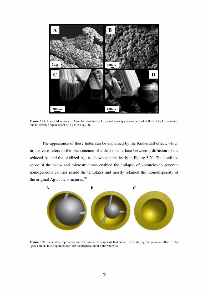
Figure 3.19: HR-SEM images of Ag-cubic structures (A, B) and consequent evidence of hollowed AgAu structures due to galvanic replacement of Ag to Au (C, D).
The appearance of these holes can be explained by the Kinkerdall effect, which
in this case refers to the phenomenon of a drift of interface between a diffusion of the
reduced Au and the oxidized Ag; as shown schematically in Figure 3.20. The confined
space of the nano- and microstructures enabled the collapse of vacancies to generate
homogeneous cavities inside the templates and mostly retained the monodispersity of
the original Ag-cubic structures.50
Figure 3.20: Schematic representation of consecutive stages of Kirkendall Effect during the galvanic effect of Ag (grey colour) to Au (gold colour) for the preparation of hollowed NPs.
A B C
75
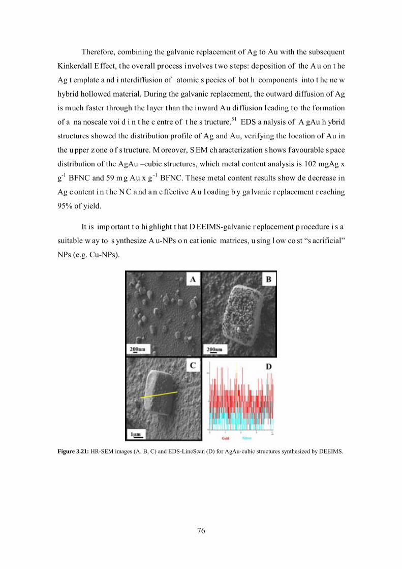
Therefore, combining the galvanic replacement of Ag to Au with the subsequent
Kinkerdall Effect, the overall process involves two s teps: deposition of the Au on t he
Ag t emplate a nd i nterdiffusion of atomic s pecies of bot h components into t he ne w
hybrid hollowed material. During the galvanic replacement, the outward diffusion of Ag
is much faster through the layer than the inward Au diffusion leading to the formation
of a na noscale voi d i n t he c entre of t he s tructure.51 EDS a nalysis of A gAu h ybrid
structures showed the distribution profile of Ag and Au, verifying the location of Au in
the u pper z one o f s tructure. M oreover, S EM ch aracterization s hows f avourable s pace
distribution of the AgAu –cubic structures, which metal content analysis is 102 mgAg x
g-1 BFNC and 59 mg Au x g -1 BFNC. These metal content results show de decrease in
Ag c ontent i n t he N C a nd a n e ffective A u l oading b y ga lvanic r eplacement r eaching
95% of yield.
It is imp ortant t o hi ghlight t hat D EEIMS-galvanic r eplacement p rocedure i s a
suitable w ay to s ynthesize A u-NPs o n cat ionic matrices, u sing l ow co st “s acrificial”
NPs (e.g. Cu-NPs).
Figure 3.21: HR-SEM images (A, B, C) and EDS-LineScan (D) for AgAu-cubic structures synthesized by DEEIMS.
76
3.4 Concluding Remarks:
DEEIMS has proved to be a suitable synthetic methodology for the preparation of
BFNCs with tuned NPs distribution depending on the reducing agent used; proving that
DEE has a determinant role during the NPs appearance. Moreover, controlling the rate
of r eduction s tage, s haped – controlled D EEIMS of A g – cubic na no- and
microstructures i s achieved. T hese A g-cubic s tructures a re u sed as t emplates f or t he
preparation of A gAu – cubic m icrostructures by t he extension of D EEIMS w ith a
galvanic replacement stage.
References:
(1) Yao, J .; Yang, M.; Duan, Y . Chemistry, B iology, and Medicine of F luorescent Nanomaterials and Related Systems: New Insights into Biosensing, Bioimaging, Genomics, Diagnostics, and Therapy. Chem. Rev. 2014.
(2) Savage, N .; D iallo, M . S.; D uncan, J .; S treet, A .; S ustich, R . Nanotechnology Applications for Clean Water; First.; William Andrew Inc: Nueva York, 2009.
(3) Morose, G . T he 5 P rinciples of “ Design for S afer N anotechnology.”J. Clean. Prod. 2010, 18, 285–289.
(4) Dahl, J . a ; Maddux, B . L. S .; Hutchison, J . E . Toward Greener N anosynthesis. Chem. Rev. 2007, 107, 2228–2269.
(5) Gubin, S. P. Magnetic Nanoparticles. 2009.
(6) Akamatsu, K .; S hinkai, H .; Ikeda, S .; A dachi, S .; N awafune, H .; T omita, S . Controlling Interparticle S pacing a mong M etal N anoparticles t hrough M etal-Catalyzed Decomposition of S urrounding P olymer M atrix. J. Am. Chem. Soc. 2005, 127, 7980–7981.
(7) Nicolais, L.; Carotenuto, G . Metal-Polymer Nanocomposites; A J OHN WILEY & SONS, INC: New Jersey, 2005.
(8) Ozkan, U. Design of Heterogeneous Catalysts; Wiley-VCH Verlag GmbH & Co. KGaA, 2009.
(9) Ruiz, P .; M uñoz, M .; Macanás, J .; M uraviev, D . N . Intermatrix S ynthesis of Polymer−Copper Nanocomposites with Tunable Parameters by Using Copper Comproportionation Reaction. Chem. Mater. 2010, 22, 6616–6623.
77

(10) Bastos-Arrieta, J.; Shafir, A.; Alonso, A.; Muñoz, M.; Macanás, J.; Muraviev, D. N. D onnan E xclusion D riven Intermatrix S ynthesis o f R eusable Polymer Stabilized Palladium Nanocatalysts. Catal. Today 2012, 193, 207–212.
(11) Bastos-Arrieta, J.; Muñoz, M.; Ruiz, P.; Muraviev, D. N. Morphological Changes of G el-Type F unctional P olymers after Intermatrix S ynthesis of P olymer Stabilized Silver Nanoparticles. Nanoscale Res. Lett. 2013, 8, 255.
(12) Ruiz, P.; Macanás, J .; Muñoz, M.; Muraviev, D. N. Intermatrix Synthesis: Easy Technique P ermitting P reparation of P olymer-Stabilized N anoparticles w ith Desired Composition and Structure. Nanoscale Res. Lett. 2011, 6, 343.
(13) Ruiz, P .; M uñoz, M .; M acanás, J .; T urta, C .; P rodius, D .; Muraviev, D . N . Intermatrix S ynthesis o f P olymer S tabilized Inorganic N anocatalyst w ith Maximum Accessibility for Reactants. Dalton Trans. 2010, 39, 1751–1757.
(14) Domènech, B .; M uñoz, M .; M uraviev, D . N .; Macanás, J . P olymer-Stabilized Palladium Nanoparticles for Catalytic Membranes: Ad Hoc Polymer Fabrication. Nanoscale Res. Lett. 2011, 6, 406.
(15) Kao, J .; T horkelsson, K .; B ai, P .; R ancatore, B . J .; X u, T . T oward F unctional Nanocomposites: T aking t he B est of N anoparticles, P olymers, a nd S mall Molecules. Chem. Soc. Rev. 2013, 42, 2654–2678.
(16) Puttamraju, P.; SenGupta, A. K. Evidence of Tunable On−Off Sorption Behaviors of Metal Oxide Nanoparticles: Role of Ion Exchanger Support. Ind. Eng. Chem. Res. 2006, 45, 7737–7742.
(17) Levenstein, R .; H asson, D .; S emiat, R . Utilization of t he D onnan E ffect f or Improving E lectrolyte S eparation w ith N anofiltration M embranes. 1996, 116, 77–92.
(18) Cumbal, L.; S engupta, A . K . A rsenic R emoval U sing P olymer-Supported Hydrated i ron(III) Oxide N anoparticles: R ole of D onnan M embrane Effect. Environ. Sci. Technol. 2005, 39, 6508–6515.
(19) Donnan, F . G. Theory of Membrane Equilibria and Membrane Potentials in the Presence o f Non-Dialysing E lectrolytes. A C ontribution t o P hysical-Chemical Physiology. J. Memb. Sci. 1995, 100, 45–55.
(20) Elliott, S. D.; Moloney, M. P.; Gun’ko, Y. K. Chiral Shells and Achiral Cores in CdS Quantum Dots. Nano Lett. 2008, 8, 2452–2457.
(21) Petryayeva, E.; A lgar, W. R .; M edintz, I. L. Quantum D ots i n B ioanalysis: A Review of Applications across Various Platforms for Fluorescence Spectroscopy and Imaging. Appl. Spectrosc. 2013, 67, 215–252.
(22) Moloney, M . P .; G un’ko, Y . K .; K elly, J . M . Chiral H ighly Luminescent C dS Quantum Dots. Chem. Commun. (Camb). 2007, 7345, 3900–3902.
78

(23) Bera, D .; Q ian, L.; T seng, T .-K.; H olloway, P . H . Q uantum D ots a nd T heir Multimodal Applications: A Review. Materials (Basel). 2010, 3, 2260–2345.
(24) Lu, A .-H.; S alabas, E. L.; S chüth, F . M agnetic N anoparticles: S ynthesis, Protection, F unctionalization, a nd A pplication. Angew. Chem. Int. Ed. Engl. 2007, 46, 1222–1244.
(25) Alonso, A.; Muñoz-Berbel, X.; Vigués, N.; Rodríguez-Rodríguez, R.; Macanás, J.; Mas, J.; Muñoz, M.; Muraviev, D. N. Intermatrix Synthesis of Monometallic and M agnetic M etal/metal O xide N anoparticles w ith B actericidal A ctivity o n Anionic Exchange Polymers. RSC Adv. 2012, 2, 4596–4599.
(26) Sau, T . K .; R ogach, A . L. N onspherical N oble M etal N anoparticles: C olloid-Chemical Synthesis and Morphology Control. Adv. Mater. 2010, 22, 1781–1804.
(27) Alonso, A .; M acanás, J .; S hafir, A .; M uñoz, M .; V allribera, A .; P rodius, D .; Melnic, S.; Turta, C.; Muraviev, D. N. Donnan-Exclusion-Driven Distribution of Catalytic Ferromagnetic Nanoparticles S ynthesized in Polymeric F ibers. Dalton Trans. 2010, 39, 2579–2586.
(28) Alonso, A .; M uñoz-Berbel, X .; V igués, N .; M acanás, J .; M uñoz, M .; Mas, J .; Muraviev, D . N . C haracterization of F ibrous P olymer S ilver/cobalt Nanocomposite w ith E nhanced B actericide A ctivity. Langmuir 2012, 28, 783 –790.
(29) Akamatsu, K .; A dachi, S.; T suruoka, T .; Ikeda, S .; T omita, S .; N awafune, H . Nanoparticles with Controlled Microstructures. 2008, 3042–3047.
(30) Akamatsu, K.; Fujii, M.; Tsuruoka, T.; Nakano, S.; Murashima, T.; Nawafune, H. Mechanistic S tudy on Microstructural T uning of M etal N anoparticle/Polymer Composite T hin Layers: H ydrogenation a nd D ecomposition of P olyimide Matrices Catalyzed by Embedded Nickel Nanoparticles. J. Phys. Chem. C 2012, 116, 17947–17954.
(31) Chou, K.-S.; Lu, Y.-C.; Lee, H.-H. Effect of Alkaline Ion on the Mechanism and Kinetics o f C hemical R eduction o f S ilver. Mater. Chem. Phys. 2005, 94, 429 –433.
(32) Songping, W .; S huyuan, M . P reparation of Ultrafine S ilver P owder U sing Ascorbic A cid a s R educing A gent a nd Its A pplication i n M LCI. Mater. Chem. Phys. 2005, 89, 423–427.
(33) Domènech, B.; Muñoz, M.; Muraviev, D. N.; Macanás, J. Uncommon Patterns in Nafion Films Loaded with Silver Nanoparticles. Chem. Commun. (Camb). 2014, 50, 4693–4695.
(34) Muraviev, D.; Macanas, J.; Farre, M.; Munoz, M.; Alegret, S. Novel Routes for Inter-Matrix S ynthesis an d C haracterization o f P olymer S tabilized M etal Nanoparticles f or M olecular R ecognition D evices. Sensors Actuators B Chem. 2006, 118, 408–417.
79
(35) Domènech, B.; Muñoz, M.; Muraviev, D. N.; Macanás, J . Catalytic Membranes with Palladium Nanoparticles: From Tailored Polymer to Catalytic Applications. Catal. Today 2012, 193, 158–164.
(36) Personick, M . L.; M irkin, C . a . M aking S ense of t he M ayhem be hind S hape Control i n t he S ynthesis of G old N anoparticles. J. Am. Chem. Soc. 2013, 135, 18238–18247.
(37) Ghosh, S . K .; P al, T . Interparticle C oupling E ffect on t he S urface P lasmon Resonance o f G old N anoparticles: F rom T heory to A pplications. Chem. Rev. 2007, 107, 4797–4862.
(38) An, C. J.; Yoo, H.-W.; Cho, C.; Park, J .-M.; Choi, J. K.; Jin, M. L.; Lee, J .-Y.; Jung, H .-T. S urface P lasmon A ssisted H igh P erformance T op-Illuminated Polymer Solar Cells with Nanostructured Ag Rear Electrodes. J. Mater. Chem. A 2014, 2, 2915.
(39) Suber, L.; Sondi, I.; Matijević, E.; Goia, D. V. Preparation and the Mechanisms of F ormation of S ilver Particles of Different Morphologies i n H omogeneous Solutions. J. Colloid Interface Sci. 2005, 288, 489–495.
(40) Goia, D . V ; M atijevic, E . P reparation of M onodispersed M etal P articles. 1998, 1203–1215.
(41) Alonso, A .; V igués, N .; M uñoz-Berbel, X .; M acanás, J .; M uñoz, M .; Mas, J .; Muraviev, D . N . E nvironmentally-Safe B imetallic A g@Co M agnetic Nanocomposites w ith A ntimicrobial A ctivity. Chem. Commun. (Camb). 2011, 47, 10464–10466.
(42) Alonso, a .; Shafir, a .; Macanás, J .; Vallribera, a .; Muñoz, M.; Muraviev, D . N . Recyclable P olymer-Stabilized N anocatalysts w ith E nhanced A ccessibility f or Reactants. Catal. Today 2012.
(43) Personick, M. L.; Langille, M. R.; Zhang, J.; Mirkin, C. a. Shape Control of Gold Nanoparticles b y S ilver Underpotential Deposition. Nano Lett. 2011, 11, 3394–3398.
(44) Jana, N. R .; Gearheart, L.; Murphy, C . J . Seed-Mediated Growth Approach for Shape-Controlled S ynthesis of S pheroidal and R od-like G old N anoparticles Using a Surfactant Template. Adv. Mater. 2001, 13, 1389–1393.
(45) Luque, R .; Balu, A. M.; Campelo, J . M.; Gonzalez-Arellano, C .; Gracia, M. J .; Luna, D .; M arinas, J . M.; R omero, A . A . T unable S hapes i n Supported M etal Nanoparticles: From Nanoflowers to Nanocubes. Mater. Chem. Phys. 2009, 117, 408–413.
(46) Adair, J. H.; Suvaci, E. Morphological Control of Particles. Curr. Opin. Colloid Interface Sci. 2000, 5, 160–167.
80
(47) Anastas, P .; E ghbali, N . G reen C hemistry: P rinciples a nd P ractice. Chem. Soc. Rev. 2010, 39, 301–312.
(48) Biswas, K.; Varghese, N.; Rao, C. N. R. Growth Kinetics of Gold Nanocrystals: A Combined Small-Angle X-Ray Scattering and Calorimetric Study. Small 2008, 4, 649–655.
(49) Jana, N. R. Gram-Scale Synthesis of Soluble, near-Monodisperse Gold Nanorods and Other Anisotropic Nanoparticles. Small 2005, 1, 875–882.
(50) Liu, Y .; G oebl, J .; Y in, Y . T emplated S ynthesis of N anostructured M aterials. Chem. Soc. Rev. 2013, 42, 2610–2653.
(51) Wang, W .; D ahl, M .; Yin, Y . H ollow N anocrystals t hrough t he N anoscale Kirkendall E Ff Ect. 2013.
(52) Odom, T. W.; Schatz, G. C. Introduction to Plasmonics. Chem. Rev. 2011, 111, 3667–3668.
(53) Aherne, D .; G ara, M .; K elly, J . M .; G un’ko, Y. K . F rom A g N anoprisms t o Triangular AuAg Nanoboxes. Adv. Funct. Mater. 2010, 20, 1329–1338.
(54) Carraro, C.; Maboudian, R.; Magagnin, L. Metallization and Nanostructuring of Semiconductor S urfaces b y G alvanic D isplacement P rocesses. Surf. Sci. Rep. 2007, 62, 499–525.
(55) Njoki, P. N.; Wu, W.; Lutz, P.; Maye, M. M. Growth Characteristics and Optical Properties o f C ore/Alloy N anoparticles F abricated v ia t he Layer-by-Layer Hydrothermal Route. Chem. Mater. 2013, 25, 3105–3113.
81
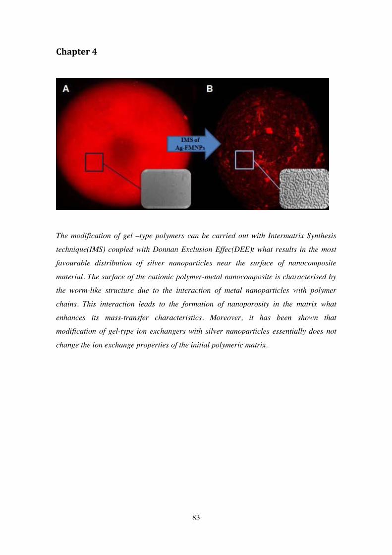
Chapter 4
The modification of gel –type polymers can be carried out with Intermatrix Synthesis
technique(IMS) coupled with Donnan Exclusion Effec(DEE)t what results in the most
favourable distribution of silver nanoparticles near the surface of nanocomposite
material. The surface of the cationic polymer-metal nanocomposite is characterised by
the worm-like structure due to the interaction of metal nanoparticles with polymer
chains. This interaction leads to the formation of nanoporosity in the matrix what
enhances its mass-transfer characteristics. Moreover, it has been shown that
modification of gel-type ion exchangers with silver nanoparticles essentially does not
change the ion exchange properties of the initial polymeric matrix.
83

4. Evaluation of ion exchange properties and morphology
changes due to IMS of Ag-FMNPs on gel –type polymeric
matrices.
Intermatrix S ynthesis ( IMS) technique c oupled with t he D onnan E xlusion Effect
(DEE) pr ovides a n e nvironmentally f riendly r oute f or t he m odification of r eactive
polymer s urfaces w ith f unctional m etal n anoparticles ( FMNPs).1 P revious r eports on
the a pplication of IMS f or t he pr eparation of p olymer-metal Nanocomposites (NCs)
proof t he m ost f avourable di stribution of t he F MNPs ne ar t he s urface of t he hos t
polymeric matrix with no evident agglomerates. The results of the modification of gel-
type i on ex change p olymeric m atrices ( cationic a nd a nionic) w ith A g-FMNPs ar e
presented in t his s ection. As the a im of t he application of IMS i s obt aining an added
value N C m aterial; t he i nitial i on e xchange f eatures of t he pol ymeric s upport a re
evaluated to proof the bifunctionality of these novel polymer-metal NCs (PMNCs).
4.1 Morphological changes on gel-type cationic polymer due to
IMS of Ag-FMNPs:
Depending on t he f inal a pplication of i nterest f or t hese NCs catalytic o r
bactericide activity, and with the goal to obtain the most favourable distribution of NPs
in t he pol ymer, IMS m ethodology ha s b een c oupled w ith t he D EE ( DEEIMS). T he
distribution of FMNPs near the surface of the NC material may be considered as really
the m ost f avourable f or pr actical a pplication of NCs of t his t ype a s i t pr ovides a n
enhanced acc ess o f t he s ubstrates ( in cat alytic ap plications) o r b acteria ( in w ater
disinfection) to the FMNPs layer of the NC.
The general DEEIMS of Ag-FMNPs was carried out by loading of the functional
groups of 400mg the gel-type sulfonic polymer with Ag+ by using 0.1 mol×L-1 aqueous
AgNO3 solution ( 20mL) f ollowed b y reduction w ith 0.1 m ol×L-1 aqueous N aBH4.
Some kinetic studies were developed by changing metal loading time at stage 1 of IMS.
Figure 4.1 shows distribution of Ag–FMNPs in the NC where a desirable metal content
84
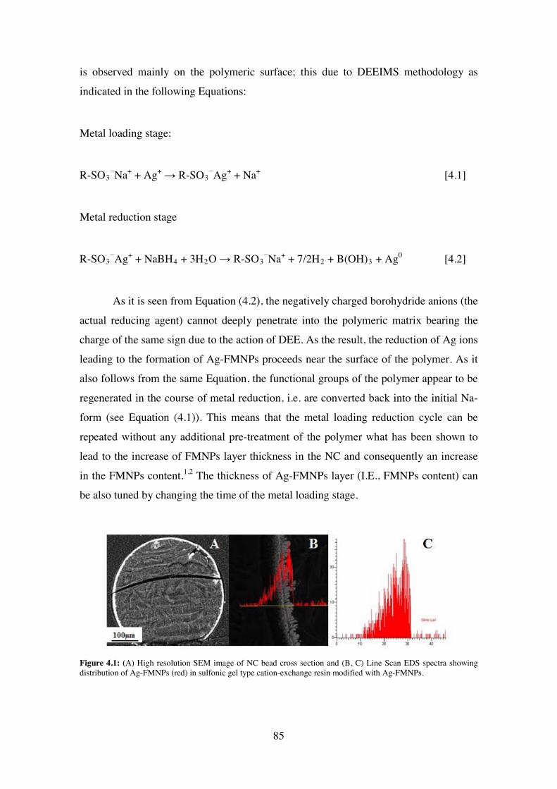
is observed mainly on the polymeric surface; this due to DEEIMS methodology as
indicated in the following Equations:
Metal loading stage:
R-SO3−Na+ + Ag+ → R-SO3
−Ag+ + Na+ [4.1]
Metal reduction stage
R-SO3−Ag+ + NaBH4 + 3H2O → R-SO3
−Na+ + 7/2H2 + B(OH)3 + Ag0 [4.2]
As it is seen from Equation (4.2), the negatively charged borohydride anions (the
actual reducing agent) cannot deeply penetrate into the polymeric matrix bearing the
charge of the same sign due to the action of DEE. As the result, the reduction of Ag ions
leading to the formation of Ag-FMNPs proceeds near the surface of the polymer. As it
also follows from the same Equation, the functional groups of the polymer appear to be
regenerated in the course of metal reduction, i.e. are converted back into the initial Na-
form (see Equation (4.1)). This means that the metal loading reduction cycle can be
repeated without any additional pre-treatment of the polymer what has been shown to
lead to the increase of FMNPs layer thickness in the NC and consequently an increase
in the FMNPs content.1,2 The thickness of Ag-FMNPs layer (I.E., FMNPs content) can
be also tuned by changing the time of the metal loading stage.
Figure 4.1: (A) High resolution SEM image of NC bead cross section and (B, C) Line Scan EDS spectra showing distribution of Ag-FMNPs (red) in sulfonic gel type cation-exchange resin modified with Ag-FMNPs.
85
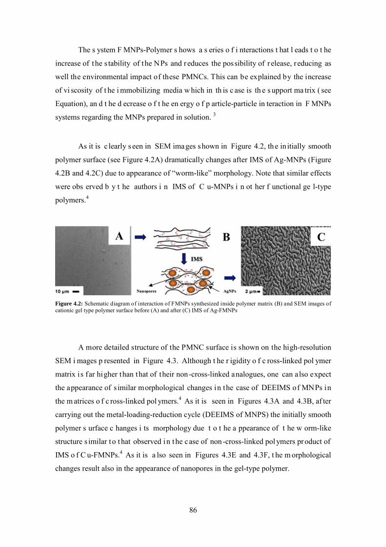
The s ystem F MNPs-Polymer s hows a s eries o f i nteractions t hat l eads t o t he
increase of the s tability of the NPs and reduces the possibility of r elease, reducing as
well the environmental impact of these PMNCs. This can be explained by the increase
of vi scosity of t he i mmobilizing media w hich in th is c ase is th e s upport ma trix ( see
Equation), an d t he d ecrease o f t he en ergy o f p article-particle in teraction in F MNPs
systems regarding the MNPs prepared in solution. 3
As it is c learly s een in SEM images shown in Figure 4.2, the in itially smooth
polymer surface (see Figure 4.2A) dramatically changes after IMS of Ag-MNPs (Figure
4.2B and 4.2C) due to appearance of “worm-like” morphology. Note that similar effects
were obs erved b y t he authors i n IMS of C u-MNPs i n ot her f unctional ge l-type
polymers.4
Figure 4.2: Schematic diagram of interaction of FMNPs synthesized inside polymer matrix (B) and SEM images of cationic gel type polymer surface before (A) and after (C) IMS of Ag-FMNPs
A more detailed structure of the PMNC surface is shown on the high-resolution
SEM i mages p resented in Figure 4.3. Although t he r igidity o f c ross-linked pol ymer
matrix is far higher than that of their non-cross-linked analogues, one can also expect
the appearance of s imilar morphological changes in the case of DEEIMS of MNPs in
the m atrices o f c ross-linked pol ymers.4 As it is seen in Figures 4.3A and 4.3B, af ter
carrying out the metal-loading-reduction cycle (DEEIMS of MNPS) the initially smooth
polymer s urface c hanges i ts morphology due t o t he a ppearance of t he w orm-like
structure s imilar t o t hat observed in t he case of non-cross-linked pol ymers product of
IMS o f C u-FMNPs.4 As it is a lso seen in Figures 4.3E and 4.3F, t he m orphological
changes result also in the appearance of nanopores in the gel-type polymer.
86
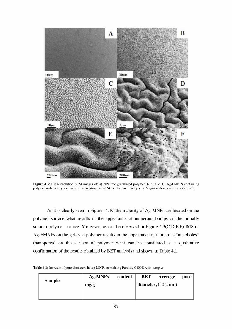
Figure 4.3: High-resolution SEM images of: a) NPs free granulated polymer. b, c, d, e, f): Ag-FMNPs containing polymer with clearly seen as worm-like structure of NC surface and nanopores. Magnification a = b < c < d< e < f
As it is clearly seen in Figures 4.1C the majority of Ag-MNPs are located on the
polymer surface what results in the appearance of numerous bumps on the initially
smooth polymer surface. Moreover, as can be observed in Figure 4.3(C,D,E,F) IMS of
Ag-FMNPs on the gel-type polymer results in the appearance of numerous “nanoholes”
(nanopores) on the surface of polymer what can be considered as a qualitative
confirmation of the results obtained by BET analysis and shown in Table 4.1.
Table 4.1: Increase of pore diameters in Ag-MNPs-containing Purolite C100E resin samples
SampleAg-MNPs content,
mg/g
BET Average pore
diameter, (±0.2 nm)
87
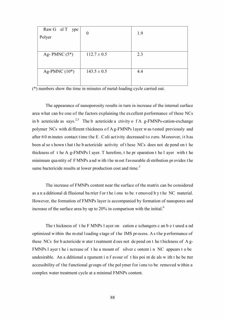
Raw G el T ype
Polyer 0 1.9
Ag- PMNC (5*) 112.7 ± 0.5 2.3
Ag-PMNC (10*) 143.5 ± 0.5 4.4
(*) numbers show the time in minutes of metal-loading cycle carried out.
The appearance of nanoporosity results in turn in increase of the internal surface
area what can be one of the factors explaining the excellent performance of these NCs
in b actericide as says.2,5 The b actericide a ctivity o f A g-FMNPs-cation-exchange
polymer NCs with di fferent t hickness o f A g-FMNPs l ayer w as t ested previously and
after 60 m inutes contact t ime t he E . C oli act ivity decreased t o z ero. Moreover, i t h as
been al so s hown t hat t he b actericide activity of t hese NCs does not de pend on t he
thickness of t he A g-FMNPs l ayer. T herefore, t he pr eparation t he l ayer with t he
minimum qua ntity of F MNPs a nd w ith t he m ost f avourable di stribution pr ovides t he
same bactericide results at lower production cost and time.5
The increase of FMNPs content near the surface of the matrix can be considered
as a n a dditional di ffusional ba rrier f or t he i ons to be r emoved b y t he NC material.
However, the formation of FMNPs layer is accompanied by formation of nanopores and
increase of the surface area by up to 20% in comparison with the initial.6
The t hickness of t he F MNPs l ayer on cation e xchangers c an b e t uned a nd
optimized w ithin the m etal l oading s tage of t he IMS pr ocess. A s t he p erformance of
these NCs for b actericide w ater t reatment d oes not de pend on t he t hickness of A g-
FMNPs l ayer t he i ncrease of t he a mount of silver c ontent i n NC appears t o be
undesirable. An a dditional a rgument i n f avour of t his poi nt de als w ith t he be tter
accessibility of t he functional groups of t he pol ymer for i ons t o be removed within a
complex water treatment cycle at a minimal FMNPs content.
88
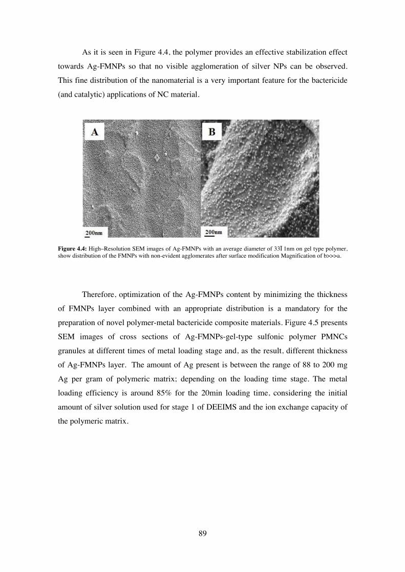
As it is seen in Figure 4.4, the polymer provides an effective stabilization effect
towards Ag-FMNPs so that no visible agglomeration of silver NPs can be observed.
This fine distribution of the nanomaterial is a very important feature for the bactericide
(and catalytic) applications of NC material.
Figure 4.4: High–Resolution SEM images of Ag-FMNPs with an average diameter of 33±1nm on gel type polymer, show distribution of the FMNPs with non-evident agglomerates after surface modification Magnification of b>>>a.
Therefore, optimization of the Ag-FMNPs content by minimizing the thickness
of FMNPs layer combined with an appropriate distribution is a mandatory for the
preparation of novel polymer-metal bactericide composite materials. Figure 4.5 presents
SEM images of cross sections of Ag-FMNPs-gel-type sulfonic polymer PMNCs
granules at different times of metal loading stage and, as the result, different thickness
of Ag-FMNPs layer. The amount of Ag present is between the range of 88 to 200 mg
Ag per gram of polymeric matrix; depending on the loading time stage. The metal
loading efficiency is around 85% for the 20min loading time, considering the initial
amount of silver solution used for stage 1 of DEEIMS and the ion exchange capacity of
the polymeric matrix.
89
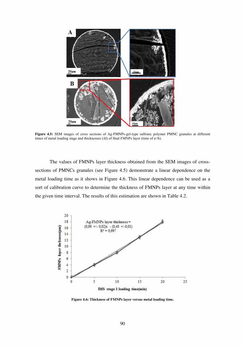
Figure 4.5: SEM images of cross sections of Ag-FMNPs-gel-type sulfonic polymer PMNC granules at different times of metal loading stage and thicknesses (Δl) of final FMNPs layer (time of a<b).
The values of FMNPs layer thickness obtained from the SEM images of cross-
sections of PMNCs granules (see Figure 4.5) demonstrate a linear dependence on the
metal loading time as it shows in Figure 4.6. This linear dependence can be used as a
sort of calibration curve to determine the thickness of FMNPs layer at any time within
the given time interval. The results of this estimation are shown in Table 4.2.
Figure 4.6: Thickness of FMNPs layer versus metal loading time.
90
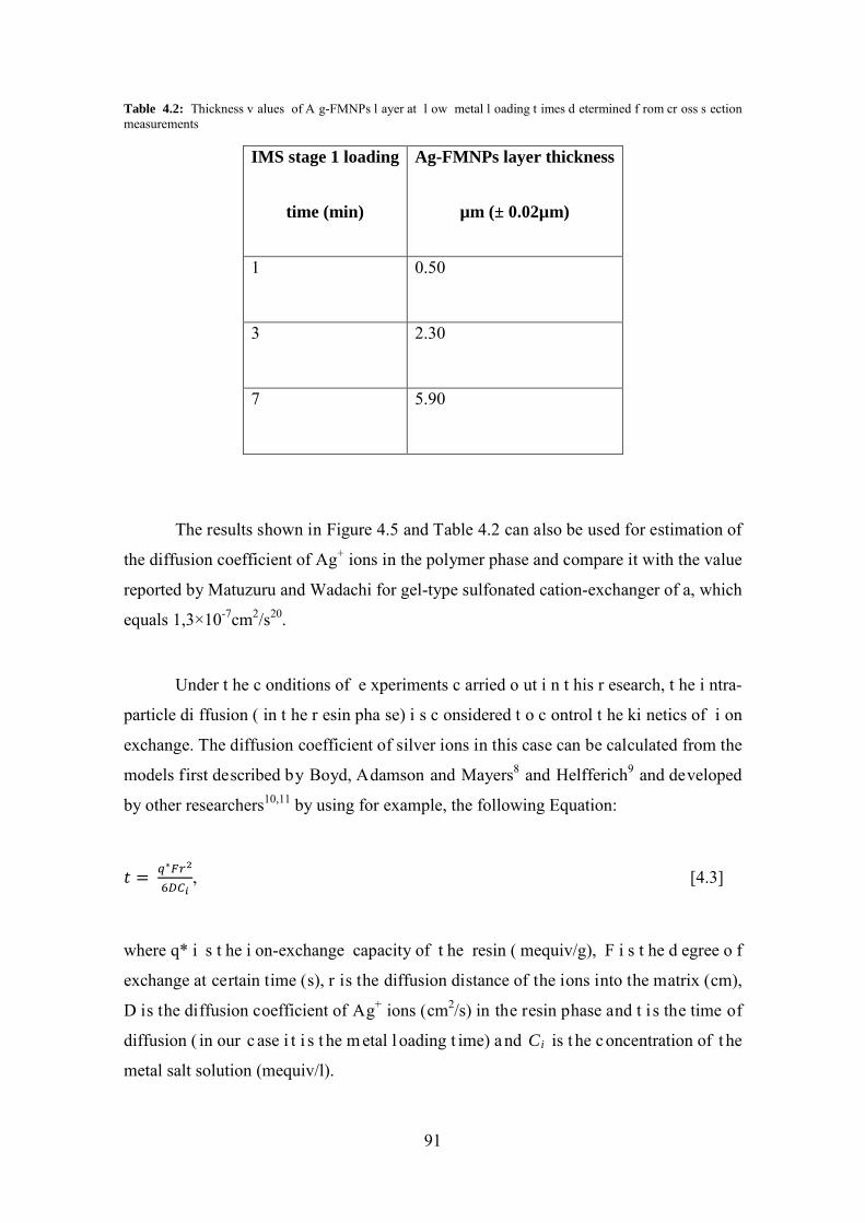
Table 4.2: Thickness v alues of A g-FMNPs l ayer at l ow metal l oading t imes d etermined f rom cr oss s ection measurements
IMS stage 1 loading
time (min)
Ag-FMNPs layer thickness
µm (± 0.02µm)
1 0.50
3 2.30
7 5.90
The results shown in Figure 4.5 and Table 4.2 can also be used for estimation of
the diffusion coefficient of Ag+ ions in the polymer phase and compare it with the value
reported by Matuzuru and Wadachi for gel-type sulfonated cation-exchanger of a, which
equals 1,3×10⁻⁷cm2/s20.
Under t he c onditions of e xperiments c arried o ut i n t his r esearch, t he i ntra-
particle di ffusion ( in t he r esin pha se) i s c onsidered t o c ontrol t he ki netics of i on
exchange. The diffusion coefficient of silver ions in this case can be calculated from the
models first described by Boyd, Adamson and Mayers8 and Helfferich9 and developed
by other researchers10,11 by using for example, the following Equation:
𝑡 = 𝑞∗𝐹𝑟2
6𝐷𝐶𝑖, [4.3]
where q* i s t he i on-exchange capacity of t he resin ( mequiv/g), F i s t he d egree o f
exchange at certain time (s), r is the diffusion distance of the ions into the matrix (cm),
D is the diffusion coefficient of Ag+ ions (cm2/s) in the resin phase and t i s the time of
diffusion ( in our c ase i t i s t he m etal l oading t ime) a nd Ci is t he c oncentration of t he
metal salt solution (mequiv/l).
91

The F value standing in Equation (4.3) can be calculated by taking into account
the thickness of the Ag-FMNPs layer (Δl, see Figure 4.5 b, right) as follows:
F = 𝑟3− (𝑟−𝛥𝑙)3
𝑟3 [4.4]
The DAg+ value calculated by using Equations (4.3) and (4.4) equals to 3.5x10-
7cm2/s, what is sufficiently close to that reported by Matuzuru and Wadachi (see above).
The d ifference b etween t he cal culated and t he r eported D v alues c an b e m ainly
attributed to the appearance of Ag-FMNPs layer near the surface of the resin beads (see
Figure 4.5) and also by possible differences in the cross linking degree of the polymer
matrices and in the other experimental conditions. In other words the resistance of the
PMNC material towards mass-transfer does not change dramatically in comparison with
the initial FMNPs-free polymer.
4.2 Evaluation of ion exchange properties of cationic and anionic gel – type polymers before and after modification with Ag-FMNPs.
The i on ex change c apacity f or t he an ionic ex changer g el–typo pol ymer
(quaternary ammine) and for the cationic exchanger gel–type (sulfonic) were calculated
by volumetric titration were 2.1 meq×g-1 in both cases.
For both anionic and cationic breakthrough experiments a column with internal
diameter of 0.025m was used for an average bed particle diameter of 500µm. F or the
breakthrough c urve pr ofile f or cationic g el –type p olymer m odified a nd unm odified
with Ag-FMNPs a fixed bed of the resin was placed in the column. A Ca2+ solution was
introduced with a pump and made go through the fixed bed particles with a flux rate of
1mL/min. T hen, each 2mL o f ef fluent w ere collected s eparated s amples f or t he
determination of displacement of Na+ to Ca2+ as described in Equation (3).
2[R-SO3−Na+]+ Ca2+ → [R-SO3
−]2Ca2+ + 2Na+ [4.5]
92
Similar pr ocedure w as f ollowed f or a nionic br eakthrough c urve profile.
Modified and unmodified with Ag-FMNPs quaternary gel-type amine anion exchanger
were used as fixed bed in the column. Cl- solution was introduced with pump and made
go t hrough t he f ixed be d pa rticles w ith a f lux rate of 1m L/min. T hen, each 2m L of
effluent were collected separated samples for the determination of displacement of OH-
to Cl- as described in Equation (4).
R-(R4-N)+OH- + Na+Cl- → R-(R4-N)+Cl- + Na+OH- [4.6]
On F igure 4.7 a re s hown t he breakthrough c urves obt ained w ithin a s eries of
experiments on displacement Na+ with Ca2+ ions from the initial polymer (FMNPs-free)
and NC samples containing different amounts of FMNPs are presented. The slope of the
curves s hown i n Figure 4.7 qualitatively reflects th e k inetic p roperties o f th e
corresponding material so that the closer it to 90o the faster is the mass transfer process
inside t he pol ymer m atrix. T his m eans t hat after D EDIMS of F MNPs t he f unctional
groups of t he i on exchanger r emain a lmost equally accessible for i ons t o be removed
from the water under treatment. At the same time what it a lso follows from the results
shown i n Figure 6, t he s lowing dow n of t he ions diffusion can b e decreased b y
minimizing the thickness of FMNPs layer moreover the negative impact of this layer is
partially compensated by the appearance of nanoporosity in NC material (see above).
93
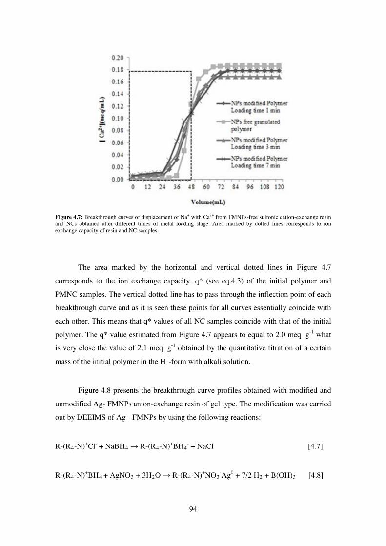
Figure 4.7: Breakthrough curves of displacement of Na+ with Ca2+ from FMNPs-free sulfonic cation-exchange resin and NCs obtained after different times of metal loading stage. Area marked by dotted lines corresponds to ion exchange capacity of resin and NC samples.
The area marked by the horizontal and vertical dotted lines in Figure 4.7
corresponds to the ion exchange capacity, q* (see eq.4.3) of the initial polymer and
PMNC samples. The vertical dotted line has to pass through the inflection point of each
breakthrough curve and as it is seen these points for all curves essentially coincide with
each other. This means that q* values of all NC samples coincide with that of the initial
polymer. The q* value estimated from Figure 4.7 appears to equal to 2.0 meq×g-1 what
is very close the value of 2.1 meq×g-1 obtained by the quantitative titration of a certain
mass of the initial polymer in the H+-form with alkali solution.
Figure 4.8 presents the breakthrough curve profiles obtained with modified and
unmodified Ag- FMNPs anion-exchange resin of gel type. The modification was carried
out by DEEIMS of Ag - FMNPs by using the following reactions:
R-(R4-N)+Cl- + NaBH4 → R-(R4-N)+BH4- + NaCl [4.7]
R-(R4-N)+BH4 + AgNO3 + 3H2O → R-(R4-N)+NO3-Ag0 + 7/2 H2 + B(OH)3 [4.8]
94
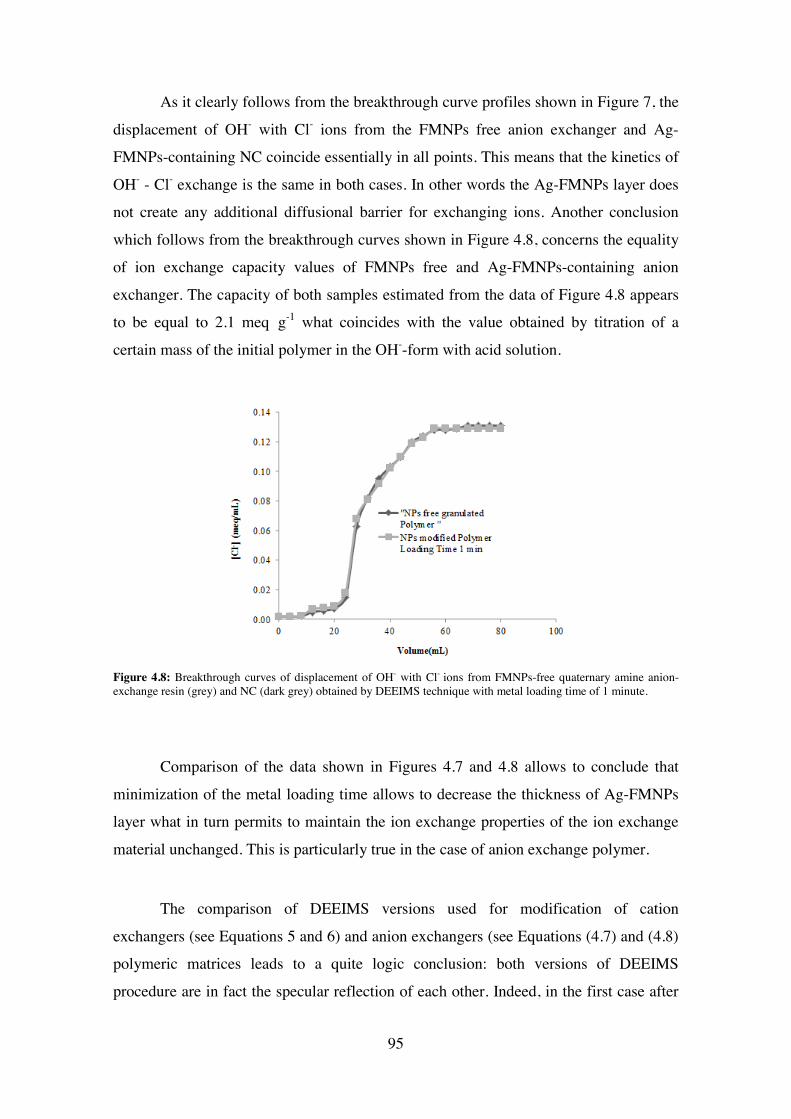
As it clearly follows from the breakthrough curve profiles shown in Figure 7, the
displacement of OH- with Cl- ions from the FMNPs free anion exchanger and Ag-
FMNPs-containing NC coincide essentially in all points. This means that the kinetics of
OH- - Cl- exchange is the same in both cases. In other words the Ag-FMNPs layer does
not create any additional diffusional barrier for exchanging ions. Another conclusion
which follows from the breakthrough curves shown in Figure 4.8, concerns the equality
of ion exchange capacity values of FMNPs free and Ag-FMNPs-containing anion
exchanger. The capacity of both samples estimated from the data of Figure 4.8 appears
to be equal to 2.1 meq×g-1 what coincides with the value obtained by titration of a
certain mass of the initial polymer in the OH--form with acid solution.
Figure 4.8: Breakthrough curves of displacement of OH- with Cl- ions from FMNPs-free quaternary amine anion-exchange resin (grey) and NC (dark grey) obtained by DEEIMS technique with metal loading time of 1 minute.
Comparison of the data shown in Figures 4.7 and 4.8 allows to conclude that
minimization of the metal loading time allows to decrease the thickness of Ag-FMNPs
layer what in turn permits to maintain the ion exchange properties of the ion exchange
material unchanged. This is particularly true in the case of anion exchange polymer.
The comparison of DEEIMS versions used for modification of cation
exchangers (see Equations 5 and 6) and anion exchangers (see Equations (4.7) and (4.8)
polymeric matrices leads to a quite logic conclusion: both versions of DEEIMS
procedure are in fact the specular reflection of each other. Indeed, in the first case after
95
the l oading of t he f unctional gr oups w ith m etal i ons ( Equation (4.1)) t he p olymer i s
treated with reducing agent (Equation (4.2)), anions of which (the actual reducer) bear
the same charge (negative) as the functional groups of the polymer. Due to the action of
DEE t hey cannot de eply penetrate i nside t he m atrix a nd t he reduction of m etal ions
leading to formation of FMNPs proceeds near the polymer surface (see Figure 4.1C).
In the case of anion exchange polymer, the first stage of DEEIMS is the sorption
of t he r educer anions on t he pos itively charged f unctional g roups of t he pol ymer
(Equation (4.7)). The second stage (Equation (4.8)) is the treatment of the polymer with
solution of pos itively charged m etal i ons. T heir r ejection b y t he m atrix be aring t he
charge of the same sign does not allow them to deeply penetrate into the polymer and
their interaction with reducing agent proceeds (as in the previous case) near the surface
of t he pol ymer. It s eems i mportant t o e mphasize t hat bot h ve rsions of D EEIMS
technique lead to the most favourable distribution of FMNPs near the surface of PMNC
material, w hat is p articularly imp ortant in p ractical a pplication o f s uch materials f or
complex w ater t reatment. N ote t hat s imilar p rocedure h as b een al so ap plied f or t he
synthesis of metal oxide nanoparticles inside ion exchange resins for removal of arsenic
from water12 and for the preparation of heterogeneous catalysts.13
96
4.3 Concluding Remarks
The surface m odification o f i on ex change m aterials w ith F MNPs b y DEEIMS
technique has shown to provide the most favourable distribution of FMNPs in the final
NC materials enhancing their feasible applications such as complex water treatment and
heterogeneous catalysis. T his t echnique ha s de monstrated t o be a n e fficient synthetic
methodology applicable f or t he pr eparation of bi functional pol ymer-metal NCs from
polymers of either functionality, i .e. bearing either negatively (e.g., cation exchangers)
or positively (e.g., anion exchangers) charged functional groups. Regarding this fact, the
modification of pol ymers w ith ne gatively c harged f unctional gr oups w ith F MNPs b y
using D EEIMS t echnique s howed t o be a ccompanied b y t he r egeneration of t he
functional groups, i .e. their conversion into the initial Na+-form. This permit to easily
increase the thickness of FMNPs layer (if required) by carrying out consecutive metal-
loading-reduction DEEIMS cycles.
In addition, t he i on e xchange c apacity of t he F MNPs m odified pol ymers i s not
essentially changed after D EEIMS a s i t c an be d educed f rom t he br eakthrough c urve
profiles obt ained on t he unm odified a nd m odified m atrices w ith F MNPs. A s i t a lso
follows f rom t hese da ta, t he r esistance of t he matrix t owards i ons di ffusion c an b e
minimized by varying the thickness o f FMNPs layer and can reach the same value as
that of the unmodified polymer.
Particularly, the modification of cation-exchange gel-type cation exchange polymer
of with Ag-FMNPs has shown to cause strong modification of the polymer morphology
due t o t he appearance of t he w orm-like s tructure on t he pol ymer s urface a nd t he
nanoporosity, which enhances the rate of mass transfer in the final NC material.
References:
(1) Muraviev, D . N . Inter-Matrix S ynthesis o f P olymer S tabilised M etal
Nanoparticles for Sensor Applications. Contrib. to Sci. 2005, 3, 19–32.
97
(2) Alonso, A .; V igués, N .; M uñoz-Berbel, X .; M acanás, J .; M uñoz, M .; Mas, J .;
Muraviev, D . N . E nvironmentally-Safe B imetallic A g@Co M agnetic
Nanocomposites w ith A ntimicrobial A ctivity. Chem. Commun. (Camb). 2011,
47, 10464–10466.
(3) Domènech, B.; Muñoz, M.; Muraviev, D. N.; Macanás, J. Uncommon Patterns in
Nafion Films Loaded with Silver Nanoparticles. Chem. Commun. (Camb). 2014,
50, 4693–4695.
(4) Muraviev, D.; Macanas, J.; Farre, M.; Munoz, M.; Alegret, S. Novel Routes for
Inter-Matrix S ynthesis an d C haracterization o f P olymer S tabilized M etal
Nanoparticles for M olecular R ecognition D evices. Sensors Actuators B Chem.
2006, 118, 408–417.
(5) Alonso, A .; M uñoz-Berbel, X .; V igués, N .; M acanás, J .; M uñoz, M .; Mas, J .;
Muraviev, D . N . C haracterization of F ibrous P olymer S ilver/cobalt
Nanocomposite w ith E nhanced Bactericide A ctivity. Langmuir 2012, 28, 783 –
790.
(6) Bastos-Arrieta, J.; Muñoz, M.; Ruiz, P.; Muraviev, D. N. Morphological Changes
of G el-Type F unctional P olymers after Intermatrix S ynthesis of P olymer
Stabilized Silver Nanoparticles. Nanoscale Res. Lett. 2013, 8, 255.
(7) Taylor, P.; Matsuzuru, H.; Wadachi, Y. Journal of Nuclear Science and Influence
of Differences in Resin-Matrix S tructure on Ion-Exchange Adsorption of Trace
Amounts of Ag ( I ), Co ( II ) and Cr ( III ) Influence of Differences in Resin-
Matrix S tructure on Ion-Exchange A dsorption of T race A mou. J. Nucl. Sci.
Technol. 1975, 12, 344–349.
(8) Boyd, G.; Adamson, A. W.; Myers, L. S. The Exchange Adsorption of Ions from
Aqueous Solutions by Organic Zeolites. II. Kinetics. J. Am. Chem. Soc. 1947, 69,
2836–2848.
(9) Helfferich, F . Ion Exchange; McGraw-Hill Book Co. Inc.: New York, 1962; p.
Chapter 6.
98
(10) Helfferich, F . Ion-Exchange K inetics. V. Ion E xchange A ccompanied b y
reactionsIon Exchange Kinetics. J. Phys. Chem. 1965, 69, 1178–1187.
(11) Helfferich, F. ION-EXCHANGE KINETICS. 1 III. EXPERIMENTAL TEST OF
THE T HEORY OF P ARTICLE-DIFFUSION C ONTROLLED ION
EXCHANGE. J. Phys. Chem. 1962, 66, 39–44.
(12) Greenleaf, J . E .; Lin, J.; S engupta, A . K . T wo N ovel A pplications of Ion
Exchange Fibers: Arsenic Removal and Chemical-Free Softening of Hard Water.
Environ. Prog. 2006, 25, 300–311.
(13) Bastos-Arrieta, J.; Shafir, A.; Alonso, A.; Muñoz, M.; Macanás, J.; Muraviev, D.
N. D onnan E xclusion D riven Intermatrix S ynthesis o f R eusable Polymer
Stabilized Palladium Nanocatalysts. Catal. Today 2012.
99
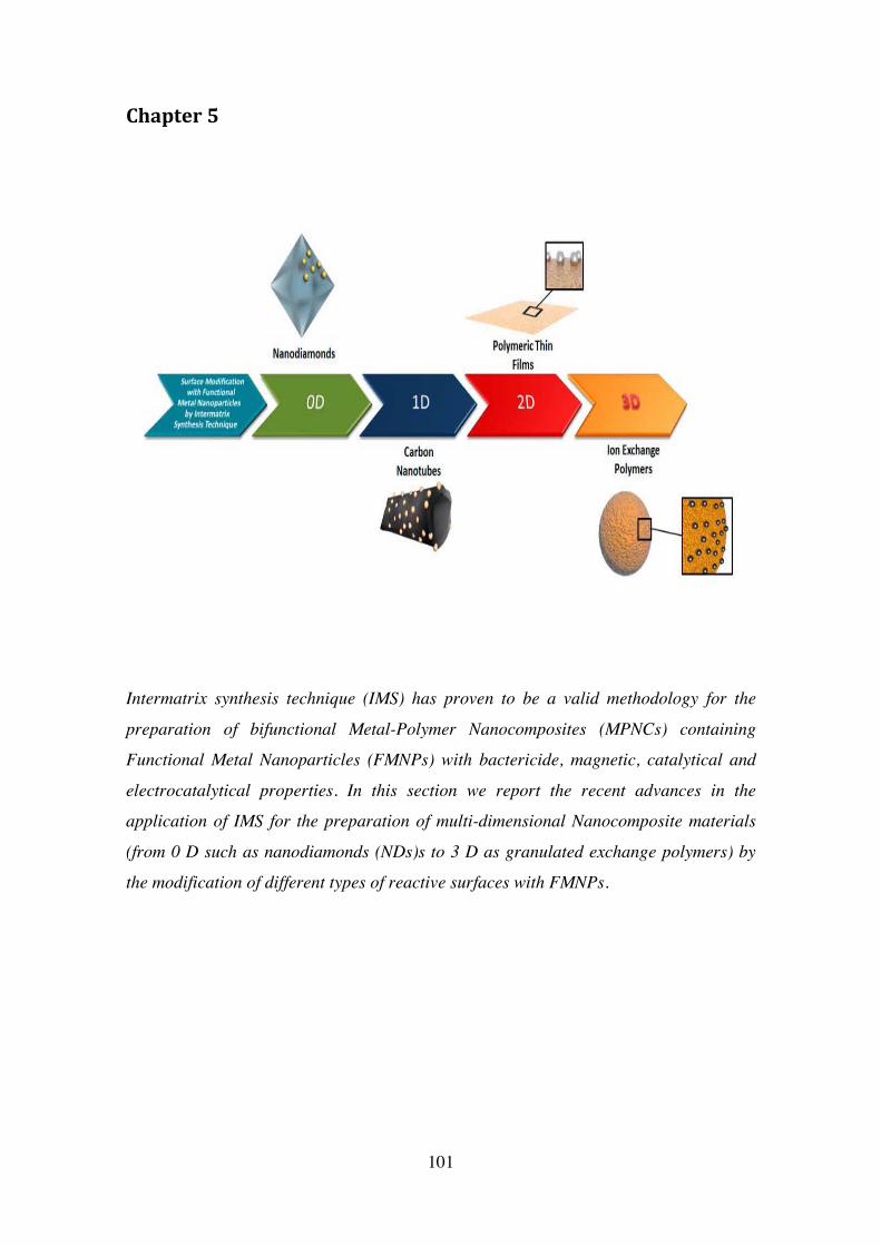
Chapter 5
Intermatrix synthesis technique (IMS) has proven to be a valid methodology for the
preparation of bifunctional Metal-Polymer Nanocomposites (MPNCs) containing
Functional Metal Nanoparticles (FMNPs) with bactericide, magnetic, catalytical and
electrocatalytical properties. In this section we report the recent advances in the
application of IMS for the preparation of multi-dimensional Nanocomposite materials
(from 0 D such as nanodiamonds (NDs)s to 3 D as granulated exchange polymers) by
the modification of different types of reactive surfaces with FMNPs.
101
5. Applications of Bifunctional Nanocomposites prepared by
Intermatrix Synthesis Technique.
5.1 Heterogeneous Catalysis:
Heterogeneous c atalysis r epresents o ne t he fields o f t he m odern s cience an d
technology where t he application o f u ltrafine cat alyst p articles d ates b ack t o t he
beginning of the last century 1,2. Application of the heterogeneous catalysis within the
last decades has been strongly stimulated by the development of the new generation of
catalysts w ith na nometer di mensions. T he de velopment of t he c atalysts of t his t ype
requires in many instances the search of appropriate supports to simplify their practical
applications.3,4
On t he ot her ha nd, t he de velopment of nove l s ynthesis a pproach r equires i n
many instances the catalysts with high quality active s ites, which are characterized by
good structure - performance relationships. This refers for example, to Carbon – Carbon
bond formation reactions, which represent a fundamental tool for organic synthesis, as it
can be used in the preparation of fine chemicals. Most frequently used reactions of this
type are palladium catalyzed C-C coupling reactions, such as for instance, Suzuki Cross
Coupling Reaction (SCCR), widely known for i ts applicability to the synthesis of fine
chemicals.5–7
Polymeric supports play in this regard a very important role for several reasons
such as, for example the ease of their preparation in the most appropriate physical form
(e.g., granulated, fibrous, membranes, etc.), the possibility to produce the macroporous
matrices w ith hi ghly developed s urface a rea a nd s ome ot hers. H owever, t he
immobilization of t he c atalyst na noparticles on t he a ppropriate pol ymeric s upport
represents a separate task, which in some instances is not so simple.8,9
The us e of t he f unctional pol ymers a s s upports f or t he he terogeneous
nanocatalysts ha s i n t his s ense, one m ore i mportant a dvantage d ealing w ith t he
possibility t o s ynthesize t he c atalyst na noparticles di rectly at t he “ point of us e”, i .e.
102
inside the supporting polymer. In the case of the metal catalyst nanoparticles (MCNPs)
this results in the formation of the catalytically-active polymer-metal nanocomposites.10
5.1.1 Synthesis and Characterization of Pd-MCNPs
The difference between the “classical” and the novel version of the IMS technique
developed i n t his s tudy be come c lear after c omparison of t he r espective r eaction
schemes, w hich c an b e written f or t he c ase o f f ormation o f P d-MCNPs in t he s trong
acid (a) and the strong base (b) functional polymers as follows:
a) IMS in cation exchange polymers (classical version):
1) Metal-loading stage
2R-COO—Na+ + [Pd(NH3)4]2+ → (R- COO-)2 [Pd (NH3)4]2+ + 2 Na+ [5.1]
2) Metal-reduction stage
(R- COO-)2 [Pd (NH3)4]2+ + 2 NaBH4 + 6H2O →
2R- SO3-Na+ + Pd0 + 7H2 + 2B(OH)3 + 4NH3. [5.2]
b) IMS in anion exchange polymers (novel version):
1) Reducer-loading stage
R-(R’4-N) +Cl- + NaBH4 → (R4-N)+BH4- + NaCl [5.3]
2) Metal-loading-reduction stage
R-(R‘4-N)+BH4- + [Pd(NH3)4]Cl2
+ 6H2O →
103
(R4-N)+Cl- Pd0 + 7H2 + 2B(OH)3 + 4NH3 [5.4]
As it is seen from the above reaction schemes, the main difference between (a)
and (b) versions of IMS consists in the f irst s tage of the process. In the first case the
functional groups of t he pol ymer a re l oaded with t he desired metal i ons, while i n t he
second case the loading is carried out with desired reducer ions. The second stage in the
first c ase c onsists i n t he r eduction of m etal i ons w ith i onic r educer, l ocated i n t he
external solution. As far as the charge sign of reducer anions coincide with that of the
polymer matrix, they cannot deeply penetrate inside the polymer due to the action of the
Donnan exclusion e ffect (DEE) and as t he r esult, t he r eduction process a ppears t o be
“localized” near the surface of the polymer.
Unlike version (a), version (b) of IMS starts with the loading of the functional
groups of the polymer with the reducer anions (see first stage, reaction 3). As the result,
the s econd s tage o f t his ve rsion pe rmits t o c ouple t he m etal-loading a nd t he m etal-
reduction pr ocesses i n one s tep. T he m etal l oading i s c arried out b y using e xternal
solution c ontaining m etal i ons be aring t he charge of t he s ame s igh as t hat of t he
functional groups of the polymer, what does not allow them to deeply diffuse inside the
polymer matrix (DEE). Again, the reduction of metal ions and therefore, the formation
of MCNPs have t o pr oceed ne ar t he s urface o f t he pol ymer. F or obvi ous r easons t he
second ve rsion of IMS t echnique (version b ) c an b e classified as a s ort of t he
symmetrical reflection of version (a).
In both versions of IMS technique DEE plays a very important role as it appears
to be r esponsible f or t he de sired nonhom ogeneous di stribution of MCNPs inside t he
polymer-metal nanocomposite. The action of this effect is observed in both cases within
the s econd s tage of IMS pr ocess (see Equations 5.2 a nd 5.4). T he following t wo
“driving f orces” a cting i n t he oppos ite di rections a re r esponsible f or t he DEE: 1) t he
electric f ield d etermined b y the charge o f t he p olymer m atrix 11–14 and 2 ) t he
concentration of the ionic component in the external solution (in fact the concentration
gradient of this component). The first force rejects the ions of the same charge as that of
the functional g roups of t he pol ymer while t he second one dr ives t hese ions t o move
into the polymer matrix. The first force can be hardly varied as it has a constant value
104
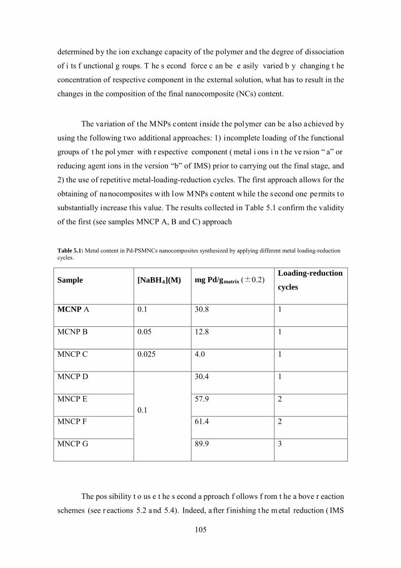
determined by the ion exchange capacity of the polymer and the degree of dissociation
of i ts f unctional g roups. T he s econd force c an be e asily varied b y changing t he
concentration of respective component in the external solution, what has to result in the
changes in the composition of the final nanocomposite (NCs) content.
The variation of the MNPs content inside the polymer can be also achieved by
using the following two additional approaches: 1) incomplete loading of the functional
groups of t he pol ymer with r espective component ( metal i ons i n t he ve rsion “ a” or
reducing agent ions in the version “b” of IMS) prior to carrying out the final stage, and
2) the use of repetitive metal-loading-reduction cycles. The first approach allows for the
obtaining of nanocomposites with low MNPs content while the second one permits to
substantially increase this value. The results collected in Table 5.1 confirm the validity
of the first (see samples MNCP A, B and C) approach
Table 5.1: Metal content in Pd-PSMNCs nanocomposites synthesized by applying different metal loading-reduction cycles.
Sample [NaBH4](M) mg Pd/gmatrix (±0.2) Loading-reduction
cycles
MCNP A 0.1 30.8 1
MCNP B 0.05 12.8 1
MNCP C 0.025 4.0 1
MNCP D
0.1
30.4 1
MNCP E 57.9 2
MNCP F 61.4 2
MNCP G 89.9 3
The pos sibility t o us e t he s econd a pproach f ollows f rom t he a bove r eaction
schemes (see r eactions 5.2 a nd 5.4). Indeed, a fter f inishing t he m etal reduction ( IMS
105
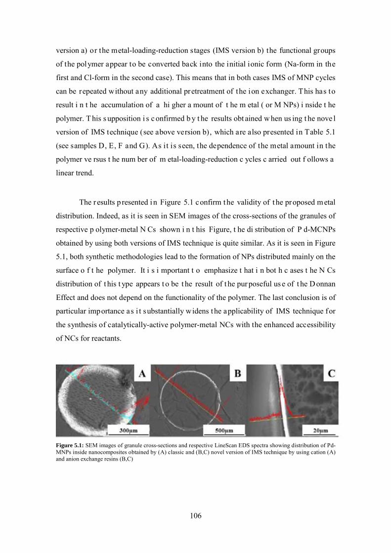
version a) or the metal-loading-reduction stages (IMS version b) the functional groups
of the polymer appear to be converted back into the initial ionic form (Na-form in the
first and Cl-form in the second case). This means that in both cases IMS of MNP cycles
can be repeated without any additional pretreatment of the ion exchanger. This has to
result i n t he accumulation of a hi gher a mount of t he m etal ( or M NPs) i nside t he
polymer. T his s upposition i s c onfirmed b y t he results obt ained w hen us ing t he nove l
version of IMS technique (see above version b), which are also presented in Table 5.1
(see samples D, E, F and G). As it is seen, the dependence of the metal amount in the
polymer ve rsus t he num ber of m etal-loading-reduction c ycles c arried out f ollows a
linear trend.
The r esults p resented i n Figure 5.1 confirm the validity of t he proposed metal
distribution. Indeed, as it is seen in SEM images of the cross-sections of the granules of
respective p olymer-metal N Cs shown i n t his Figure, t he di stribution of P d-MCNPs
obtained by using both versions of IMS technique is quite similar. As it is seen in Figure
5.1, both synthetic methodologies lead to the formation of NPs distributed mainly on the
surface o f t he polymer. It i s i mportant t o emphasize t hat i n bot h c ases t he N Cs
distribution of t his t ype appears t o be t he result of t he pur poseful us e of t he D onnan
Effect and does not depend on the functionality of the polymer. The last conclusion is of
particular importance as i t substantially widens t he applicability of IMS technique for
the synthesis of catalytically-active polymer-metal NCs with the enhanced accessibility
of NCs for reactants.
Figure 5.1: SEM images of granule cross-sections and respective LineScan EDS spectra showing distribution of Pd-MNPs inside nanocomposites obtained by (A) classic and (B,C) novel version of IMS technique by using cation (A) and anion exchange resins (B,C)
106
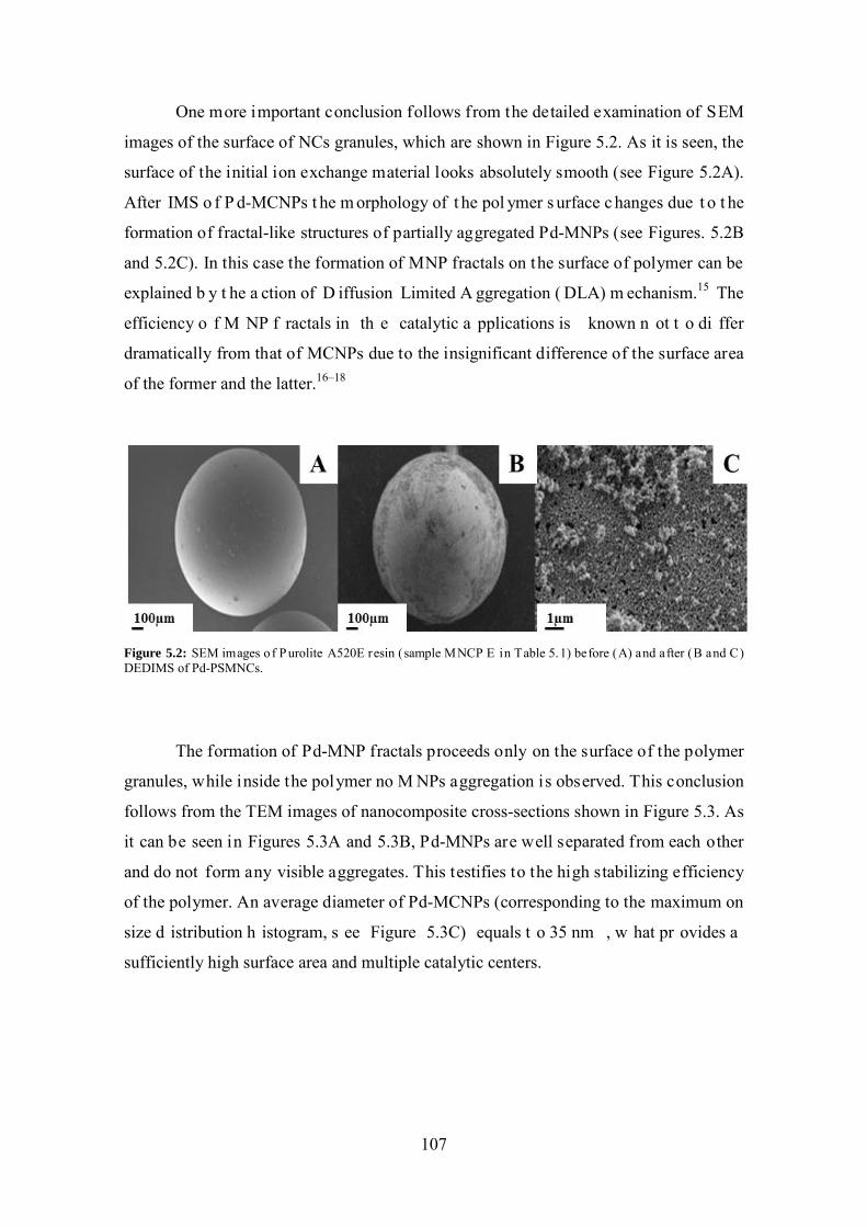
One more important conclusion follows from the detailed examination of SEM
images of the surface of NCs granules, which are shown in Figure 5.2. As it is seen, the
surface of the initial ion exchange material looks absolutely smooth (see Figure 5.2A).
After IMS o f P d-MCNPs t he m orphology of t he pol ymer s urface c hanges due t o t he
formation of fractal-like structures of partially aggregated Pd-MNPs (see Figures. 5.2B
and 5.2C). In this case the formation of MNP fractals on the surface of polymer can be
explained b y t he a ction of D iffusion Limited A ggregation ( DLA) m echanism.15 The
efficiency o f M NP f ractals in th e catalytic a pplications is known n ot t o di ffer
dramatically from that of MCNPs due to the insignificant difference of the surface area
of the former and the latter.16–18
Figure 5.2: SEM images o f Purolite A520E resin (sample MNCP E in Table 5.1) before (A) and after (B and C) DEDIMS of Pd-PSMNCs.
The formation of Pd-MNP fractals proceeds only on the surface of the polymer
granules, while inside the polymer no M NPs aggregation is observed. This conclusion
follows from the TEM images of nanocomposite cross-sections shown in Figure 5.3. As
it can be seen in Figures 5.3A and 5.3B, Pd-MNPs are well separated from each other
and do not form any visible aggregates. This testifies to the high stabilizing efficiency
of the polymer. An average diameter of Pd-MCNPs (corresponding to the maximum on
size d istribution h istogram, s ee Figure 5.3C) equals t o 35 nm , w hat pr ovides a
sufficiently high surface area and multiple catalytic centers.
107
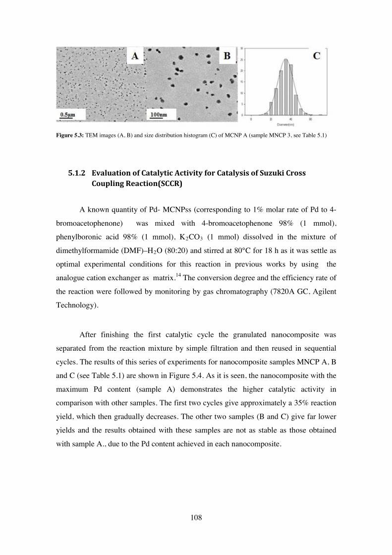
Figure 5.3: TEM images (A, B) and size distribution histogram (C) of MCNP A (sample MNCP 3, see Table 5.1)
5.1.2 Evaluation of Catalytic Activity for Catalysis of Suzuki Cross Coupling Reaction(SCCR)
A known quantity of Pd- MCNPss (corresponding to 1% molar rate of Pd to 4-
bromoacetophenone) was mixed with 4-bromoacetophenone 98% (1 mmol),
phenylboronic acid 98% (1 mmol), K2CO3 (1 mmol) dissolved in the mixture of
dimethylformamide (DMF)–H2O (80:20) and stirred at 80°C for 18 h as it was settle as
optimal experimental conditions for this reaction in previous works by using the
analogue cation exchanger as matrix.14 The conversion degree and the efficiency rate of
the reaction were followed by monitoring by gas chromatography (7820A GC, Agilent
Technology).
After finishing the first catalytic cycle the granulated nanocomposite was
separated from the reaction mixture by simple filtration and then reused in sequential
cycles. The results of this series of experiments for nanocomposite samples MNCP A, B
and C (see Table 5.1) are shown in Figure 5.4. As it is seen, the nanocomposite with the
maximum Pd content (sample A) demonstrates the higher catalytic activity in
comparison with other samples. The first two cycles give approximately a 35% reaction
yield, which then gradually decreases. The other two samples (B and C) give far lower
yields and the results obtained with these samples are not as stable as those obtained
with sample A., due to the Pd content achieved in each nanocomposite.
108
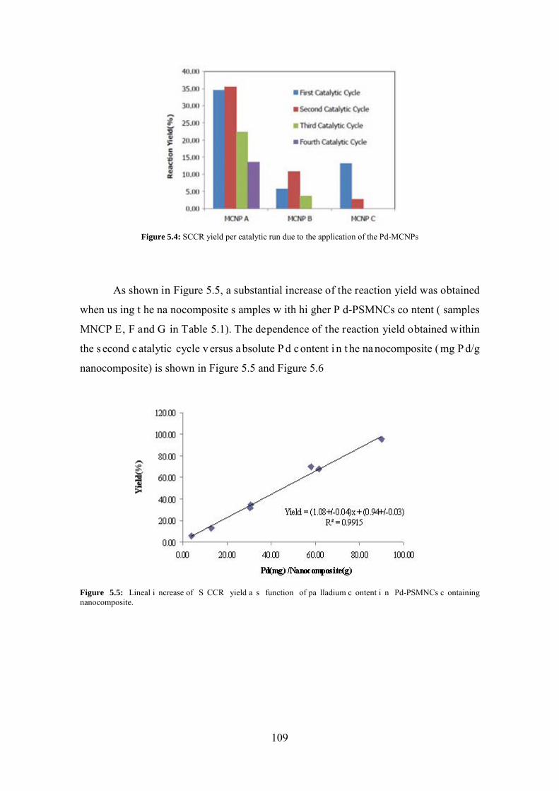
Figure 5.4: SCCR yield per catalytic run due to the application of the Pd-MCNPs
As shown in Figure 5.5, a substantial increase of the reaction yield was obtained
when us ing t he na nocomposite s amples w ith hi gher P d-PSMNCs co ntent ( samples
MNCP E, F and G in Table 5.1). The dependence of the reaction yield obtained within
the s econd c atalytic cycle v ersus a bsolute P d c ontent i n t he na nocomposite ( mg P d/g
nanocomposite) is shown in Figure 5.5 and Figure 5.6
Figure 5.5: Lineal i ncrease of S CCR yield a s function of pa lladium c ontent i n Pd-PSMNCs c ontaining nanocomposite.
109
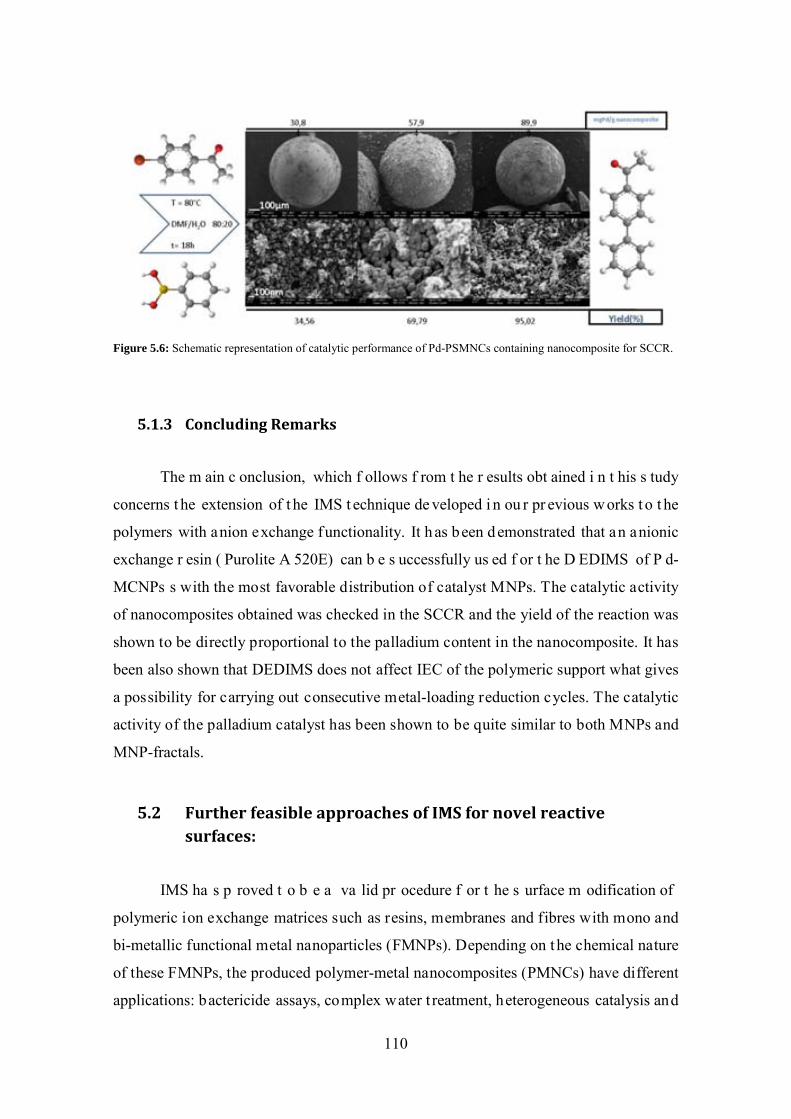
Figure 5.6: Schematic representation of catalytic performance of Pd-PSMNCs containing nanocomposite for SCCR.
5.1.3 Concluding Remarks
The m ain c onclusion, which f ollows f rom t he r esults obt ained i n t his s tudy
concerns t he extension of t he IMS t echnique de veloped i n ou r pr evious w orks t o t he
polymers with anion exchange functionality. It has been demonstrated that an anionic
exchange r esin ( Purolite A 520E) can b e s uccessfully us ed f or t he D EDIMS of P d-
MCNPs s with the most favorable distribution of catalyst MNPs. The catalytic activity
of nanocomposites obtained was checked in the SCCR and the yield of the reaction was
shown to be directly proportional to the palladium content in the nanocomposite. It has
been also shown that DEDIMS does not affect IEC of the polymeric support what gives
a possibility for carrying out consecutive metal-loading reduction cycles. The catalytic
activity of the palladium catalyst has been shown to be quite similar to both MNPs and
MNP-fractals.
5.2 Further feasible approaches of IMS for novel reactive surfaces:
IMS ha s p roved t o b e a va lid pr ocedure f or t he s urface m odification of
polymeric ion exchange matrices such as resins, membranes and fibres with mono and
bi-metallic functional metal nanoparticles (FMNPs). Depending on the chemical nature
of these FMNPs, the produced polymer-metal nanocomposites (PMNCs) have different
applications: bactericide assays, complex water t reatment, heterogeneous catalysis and
110
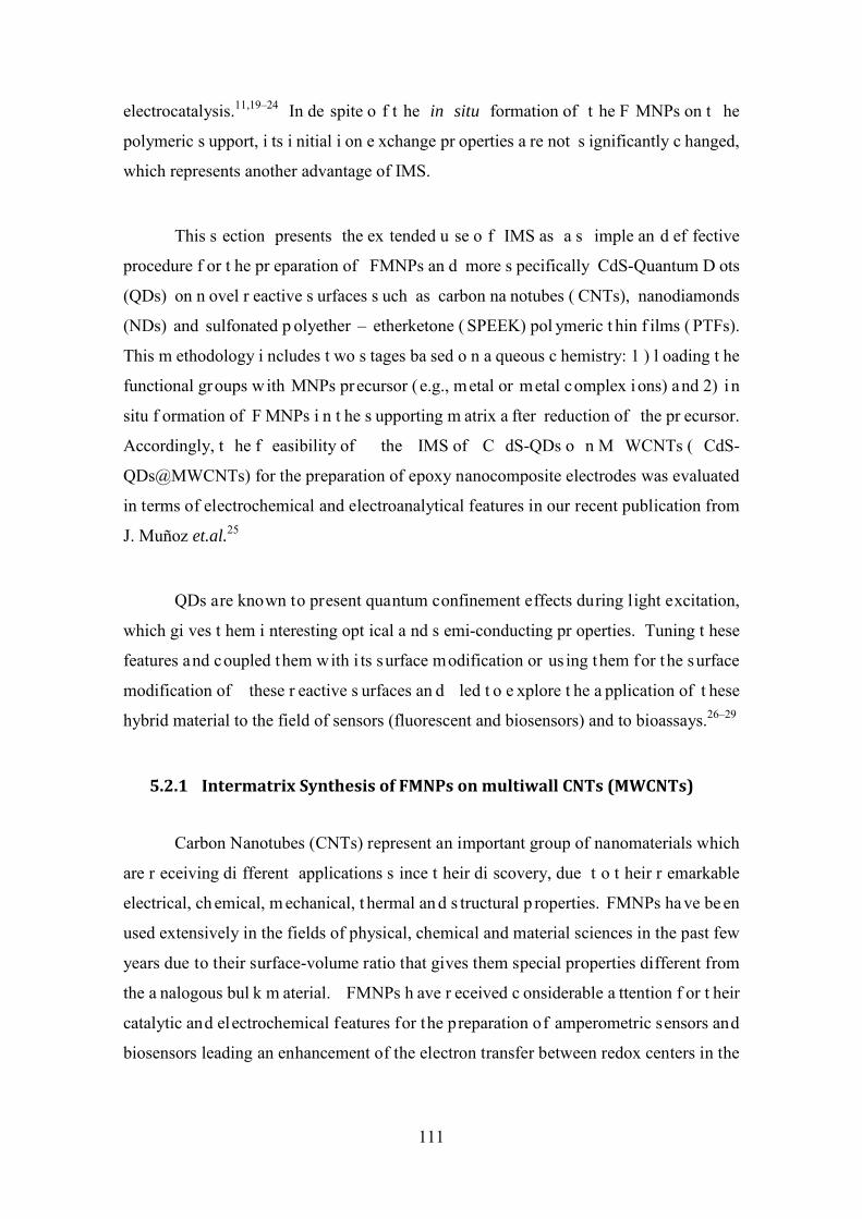
electrocatalysis.11,19–24 In de spite o f t he in situ formation of t he F MNPs on t he
polymeric s upport, i ts i nitial i on e xchange pr operties a re not s ignificantly c hanged,
which represents another advantage of IMS.
This s ection presents the ex tended u se o f IMS as a s imple an d ef fective
procedure f or t he pr eparation of FMNPs an d more s pecifically CdS-Quantum D ots
(QDs) on n ovel r eactive s urfaces s uch as carbon na notubes ( CNTs), nanodiamonds
(NDs) and sulfonated p olyether – etherketone ( SPEEK) pol ymeric t hin f ilms ( PTFs).
This m ethodology i ncludes t wo s tages ba sed o n a queous c hemistry: 1 ) l oading t he
functional groups with MNPs precursor ( e.g., metal or metal complex ions) and 2) i n
situ f ormation of F MNPs i n t he s upporting m atrix a fter reduction of the pr ecursor.
Accordingly, t he f easibility of the IMS of C dS-QDs o n M WCNTs ( CdS-
QDs@MWCNTs) for the preparation of epoxy nanocomposite electrodes was evaluated
in terms of electrochemical and electroanalytical features in our recent publication from
J. Muñoz et.al.25
QDs are known to present quantum confinement effects during light excitation,
which gi ves t hem i nteresting opt ical a nd s emi-conducting pr operties. Tuning t hese
features and coupled them with i ts surface modification or us ing them for the surface
modification of these r eactive s urfaces an d led t o e xplore t he a pplication of t hese
hybrid material to the field of sensors (fluorescent and biosensors) and to bioassays.26–29
5.2.1 Intermatrix Synthesis of FMNPs on multiwall CNTs (MWCNTs)
Carbon Nanotubes (CNTs) represent an important group of nanomaterials which
are r eceiving di fferent applications s ince t heir di scovery, due t o t heir r emarkable
electrical, ch emical, m echanical, t hermal an d s tructural p roperties. FMNPs ha ve be en
used extensively in the fields of physical, chemical and material sciences in the past few
years due to their surface-volume ratio that gives them special properties different from
the a nalogous bul k m aterial. FMNPs h ave r eceived c onsiderable a ttention f or t heir
catalytic and electrochemical features for the preparation of amperometric sensors and
biosensors leading an enhancement of the electron transfer between redox centers in the
111
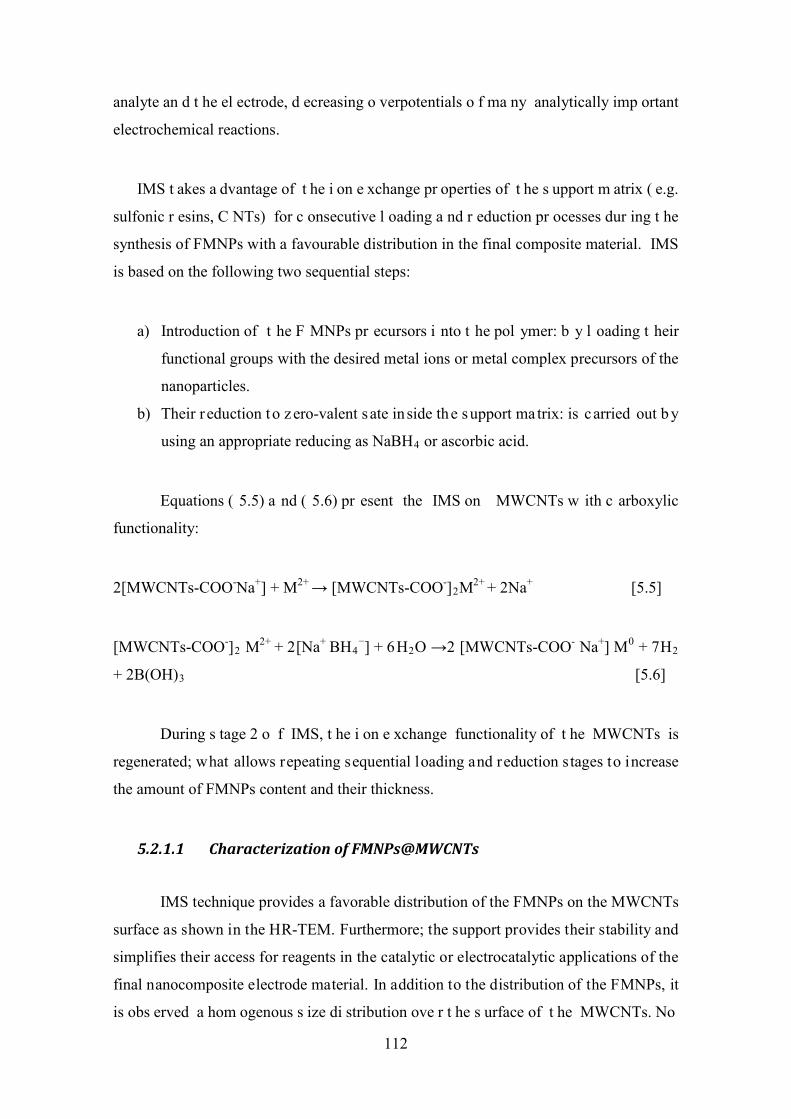
analyte an d t he el ectrode, d ecreasing o verpotentials o f ma ny analytically imp ortant
electrochemical reactions.
IMS t akes a dvantage of t he i on e xchange pr operties of t he s upport m atrix ( e.g.
sulfonic r esins, C NTs) for c onsecutive l oading a nd r eduction pr ocesses dur ing t he
synthesis of FMNPs with a favourable distribution in the final composite material. IMS
is based on the following two sequential steps:
a) Introduction of t he F MNPs pr ecursors i nto t he pol ymer: b y l oading t heir
functional groups with the desired metal ions or metal complex precursors of the
nanoparticles.
b) Their r eduction to z ero-valent s ate inside the support matrix: is carried out b y
using an appropriate reducing as NaBH4 or ascorbic acid.
Equations ( 5.5) a nd ( 5.6) pr esent the IMS on MWCNTs w ith c arboxylic
functionality:
2[MWCNTs-COO-Na+] + M2+ → [MWCNTs-COO-]2M2+ + 2Na+ [5.5]
[MWCNTs-COO-]2 M2+ + 2[Na+ BH4−] + 6H2O →2 [MWCNTs-COO- Na+] M0 + 7H2
+ 2B(OH)3 [5.6]
During s tage 2 o f IMS, t he i on e xchange functionality of t he MWCNTs is
regenerated; what allows repeating sequential loading and reduction stages to increase
the amount of FMNPs content and their thickness.
5.2.1.1 Characterization of FMNPs@MWCNTs
IMS technique provides a favorable distribution of the FMNPs on the MWCNTs
surface as shown in the HR-TEM. Furthermore; the support provides their stability and
simplifies their access for reagents in the catalytic or electrocatalytic applications of the
final nanocomposite electrode material. In addition to the distribution of the FMNPs, it
is obs erved a hom ogenous s ize di stribution ove r t he s urface of t he MWCNTs. No
112

agglomeration of different FMNPs@MWCNTs is detected by HR-TEM images shown
in Figure 5.7.
Figure 5.7: HR-TEM images of A) raw MWCNTs; B) Ag-; C) Au-; D) Cu-; E) Pd- and F) Pt-FMNPs@MWCNTs
The identification of the metal content for Ag-FMNPs@MWCNTs case is
accomplished by EDS spectra (see Figure 5.8D) and TGA analysis (in Table 5.2)
differentiating the FMNPs from the catalyst remaining from the industrial synthesis of
the MWCNTs. The fact that the FMNPs are well distributed over the surface of the
MWCNTs leads to the idea of increasing the electrochemical conductivity and an
overall enhancement of the electrochemical features as proven in the corresponding
electroanalytical characterization.25
113
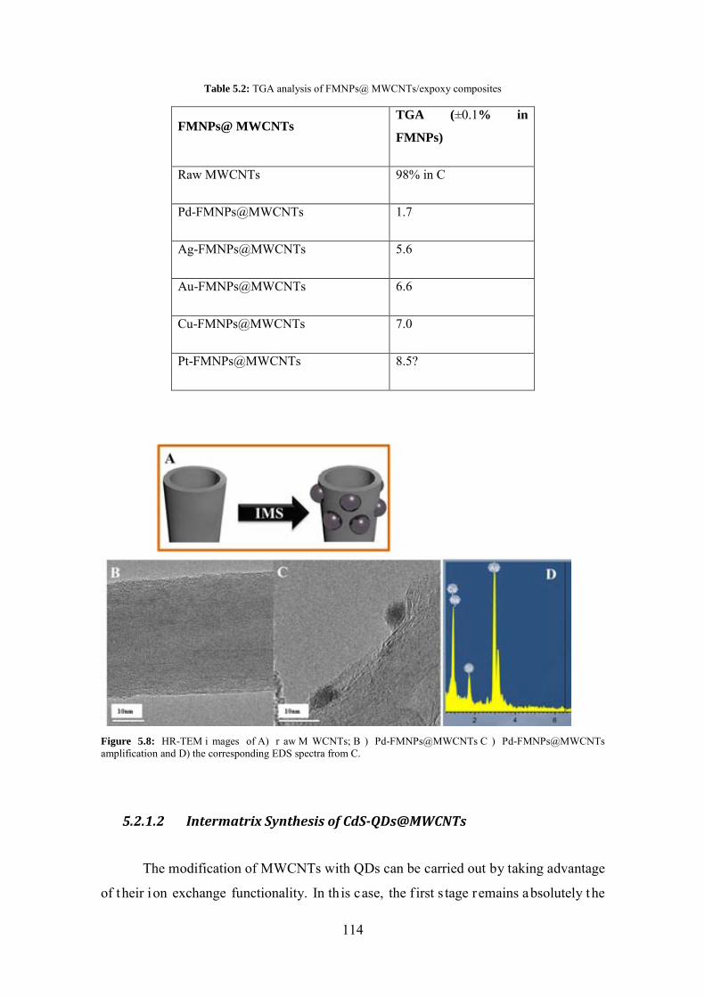
Table 5.2: TGA analysis of FMNPs@ MWCNTs/expoxy composites
FMNPs@ MWCNTs TGA (±0.1% in
FMNPs)
Raw MWCNTs 98% in C
Pd-FMNPs@MWCNTs 1.7
Ag-FMNPs@MWCNTs 5.6
Au-FMNPs@MWCNTs 6.6
Cu-FMNPs@MWCNTs 7.0
Pt-FMNPs@MWCNTs 8.5?
Figure 5.8: HR-TEM i mages of A) r aw M WCNTs; B ) Pd-FMNPs@MWCNTs C ) Pd-FMNPs@MWCNTs amplification and D) the corresponding EDS spectra from C.
5.2.1.2 Intermatrix Synthesis of CdS-QDs@MWCNTs
The modification of MWCNTs with QDs can be carried out by taking advantage
of their ion exchange functionality. In th is case, the f irst s tage remains absolutely the
114
same (loading the functional groups with NPs precursor), while the second one includes
the formation of NPs (QDs) by precipitation reaction (instead of reduction). IMS can be
described as follows: 12,30
Stage 1: Loading of Cd2+ ions ( QDs pr ecursors) ont o t he carboxylic gr oups of
MWCNTs, Equation (5.7), and
Stage 2: Precipitation of CdS-QDs on the MWCNTs surface by adding Na2S, Equation
(5.8):
2[MWCNTs-COO- Na+] + Cd2+ → [MWCNTs-COO-]2 Cd2+ + 2Na+ [5.7]
[MWCNTs-COO-]2 Cd2+ + Na2S → 2 [MWCNTs-COO- Na+] + CdS↓ [5.8]
Characterization of CdS-QDs@MWCNTs
As i t i s clearly seen f rom Equation (5.8), after carrying out the QDs formation
reaction on t he M WCNTs s urface, t he f unctional gr oups a ppear t o be r egenerated, a s
they are converted back into the Na+ form. This means that the QDs formation cycle can
be r epeated a gain b y u sing bot h Equations w ithout a ny additional pr e-treatment o f
MWCNTs. This allows for accumulation of the desired amount of QDs on the surface
of MWCNTs as seen in Figure 5.9.
Figure 5.9: A) HR-TEM raw MWCNT B) HR-(S)TEM CdS-QDs on MWCNTs after one IMS cycle. C) and d) HR-(S)TEM images of CdS-QDs on MWCNTs after two sequential IMS cycles. Magnification of D>>C.
115
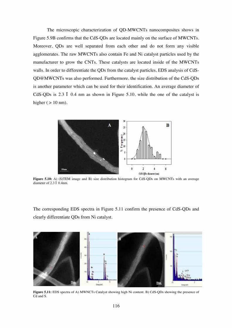
The microscopic characterization of QD-MWCNTs nanocomposites shows in
Figure 5.9B confirms that the CdS-QDs are located mainly on the surface of MWCNTs.
Moreover, QDs are well separated from each other and do not form any visible
agglomerates. The raw MWCNTs also contain Fe and Ni catalyst particles used by the
manufacturer to grow the CNTs. These catalysts are located inside of the MWCNTs
walls. In order to differentiate the QDs from the catalyst particles, EDS analysis of CdS-
QD@MWCNTs was also performed. Furthermore, the size distribution of the CdS-QDs
is another parameter which can be used for their identification. An average diameter of
CdS-QDs is 2.3 ± 0.4 nm as shown in Figure 5.10, while the one of the catalyst is
higher ( > 10 nm).
Figure 5.10: A) (S)TEM image and B) size distribution histogram for CdS-QDs on MWCNTs with an average diameter of 2.3 ± 0.4nm.
The corresponding EDS spectra in Figure 5.11 confirm the presence of CdS-QDs and
clearly differentiate QDs from Ni catalyst.
Figure 5.11: EDS spectra of A) MWNCTs Catalyst showing high Ni content. B) CdS-QDs showing the presence of Cd and S.
116
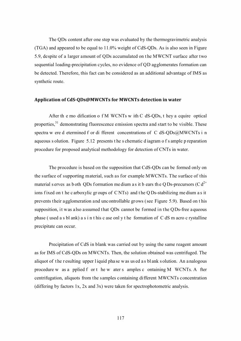
The QDs content after one step was evaluated by the thermogravimetric analysis
(TGA) and appeared to be equal to 11.0% weight of CdS-QDs. As is also seen in Figure
5.9, despite of a larger amount of QDs accumulated on t he MWCNT surface after two
sequential loading-precipitation cycles, no evidence of QD agglomerates formation can
be detected. Therefore, this fact can be considered as an additional advantage of IMS as
synthetic route.
Application of CdS-QDs@MWCNTs for MWCNTs detection in water
After th e mo dification o f M WCNTs w ith C dS-QDs, t hey a cquire optical
properties,31 demonstrating fluorescence emission spectra and start to be visible. These
spectra w ere d etermined f or di fferent concentrations of C dS-QDs@MWCNTs i n
aqueous s olution. Figure 5.12 presents t he s chematic d iagram o f s ample p reparation
procedure for proposed analytical methodology for detection of CNTs in water.
The procedure is based on the supposition that CdS-QDs can be formed only on
the surface of supporting material, such as for example MWCNTs. The surface of this
material s erves as b oth QDs f ormation me dium a s it b ears th e Q Ds-precursors (C d2+
ions f ixed on t he c arboxylic gr oups of C NTs) and t he Q Ds-stabilizing me dium a s it
prevents their agglomeration and uncontrollable grows (see Figure 5.9). Based on t his
supposition, i t was also assumed that QDs cannot be formed in the QDs-free aqueous
phase ( used a s bl ank) a s i n t his c ase onl y t he formation of C dS m acro c rystalline
precipitate can occur.
Precipitation of CdS in blank was carried out by using the same reagent amount
as for IMS of CdS-QDs on MWCNTs. Then, the solution obtained was centrifuged. The
aliquot of t he r esulting upper l iquid pha se w as us ed a s bl ank s olution. An a nalogous
procedure w as a pplied f or t he w ater s amples c ontaining M WCNTs. A fter
centrifugation, aliquots from the samples containing different MWCNTs concentration
(differing by factors 1x, 2x and 3x) were taken for spectrophotometric analysis.
117
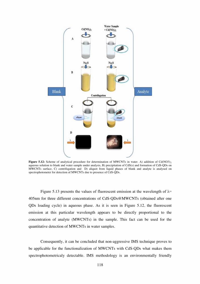
Figure 5.12: Scheme of analytical procedure for determination of MWCNTs in water. A) addition of Cd(NO3)2aqueous solution to blank and water sample under analysis, B) precipitation of CdS(s) and formation of CdS-QDs on MWCNTs surface, C) centrifugation and D) aliquot from liquid phases of blank and analyte is analysed on spectrophotometer for detection of MWCNTs due to presence of CdS-QDs.
Figure 5.13 presents the values of fluorescent emission at the wavelength of λ=
405nm for three different concentrations of CdS-QDs@MWCNTs (obtained after one
QDs loading cycle) in aqueous phase. As it is seen in Figure 5.12, the fluorescent
emission at this particular wavelength appears to be directly proportional to the
concentration of analyte (MWCNTs) in the sample. This fact can be used for the
quantitative detection of MWCNTs in water samples.
Consequently, it can be concluded that non-aggressive IMS technique proves to
be applicable for the functionalization of MWCNTs with CdS-QDs what makes them
spectrophotometricaly detectable. IMS methodology is an environmentally friendly
118
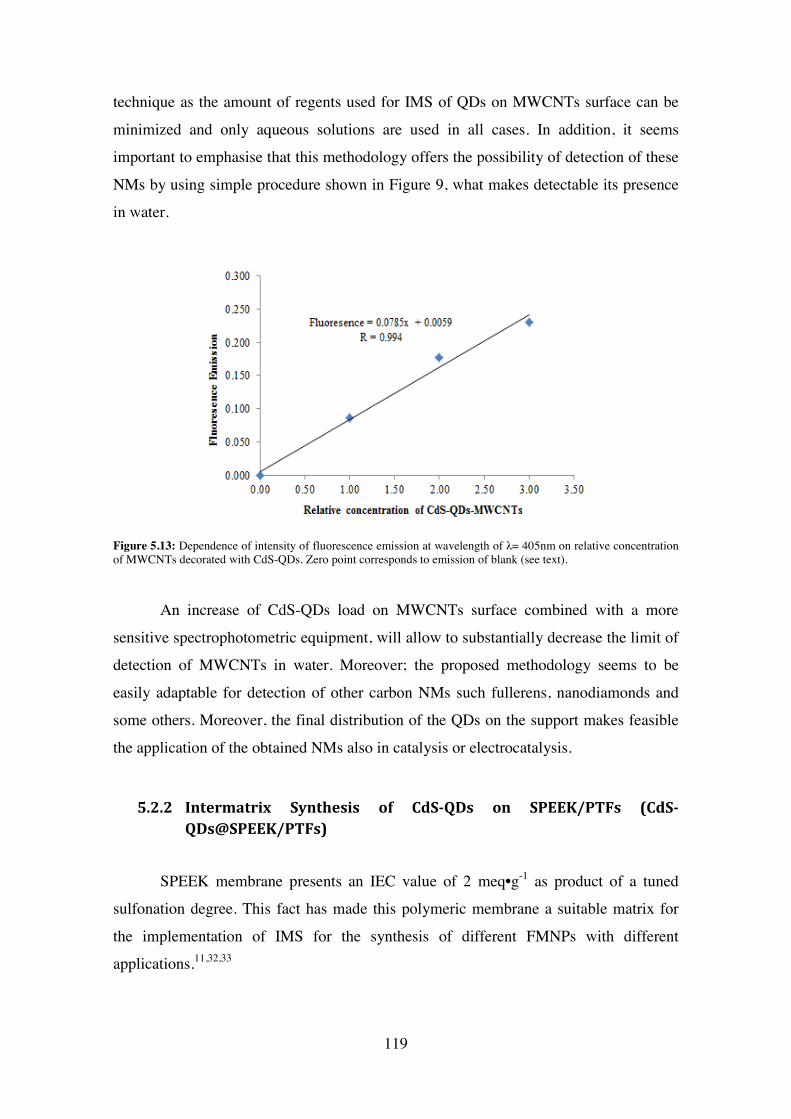
technique as the amount of regents used for IMS of QDs on MWCNTs surface can be
minimized and only aqueous solutions are used in all cases. In addition, it seems
important to emphasise that this methodology offers the possibility of detection of these
NMs by using simple procedure shown in Figure 9, what makes detectable its presence
in water.
Figure 5.13: Dependence of intensity of fluorescence emission at wavelength of λ= 405nm on relative concentrationof MWCNTs decorated with CdS-QDs. Zero point corresponds to emission of blank (see text).
An increase of CdS-QDs load on MWCNTs surface combined with a more
sensitive spectrophotometric equipment, will allow to substantially decrease the limit of
detection of MWCNTs in water. Moreover; the proposed methodology seems to be
easily adaptable for detection of other carbon NMs such fullerens, nanodiamonds and
some others. Moreover, the final distribution of the QDs on the support makes feasible
the application of the obtained NMs also in catalysis or electrocatalysis.
5.2.2 Intermatrix Synthesis of CdS-QDs on SPEEK/PTFs (CdS-QDs@SPEEK/PTFs)
SPEEK membrane presents an IEC value of 2 meq•g-1 as product of a tuned
sulfonation degree. This fact has made this polymeric membrane a suitable matrix for
the implementation of IMS for the synthesis of different FMNPs with different
applications.11,32,33
119

Preparing P TFs of S PEEK m embrane b y spin c oating ( SC) involves t he
production of a m aterial w ith opt imal pr operties, w hich c hemical pr operties a re not
changed. SC of fers a n ovel t ype of pol ymeric s upport f or IMS. S C i s c urrently a
predominant t echnique used t o pr oduce uni form t hin f ilms of or ganic m aterials with
customized t hicknesses of t he or der o f micrometres an d n anometers.34,35,36
Consequently, the re-assembly and disposition of the functionality of the initial material
for IMS of Cd-QDs.
The f ormation of S PEEK/PTFs i nvolves t he e quilibrium of s everal di fferent
species t o pr oduce t he homogenous pol ymeric l ayer. T he a pproach t o a chieve
homogeneity in the layer thickness and distribution required several optimization cycles
of SPEEK polymer dissolved and dropped on a silicon wafer. The viscosity and surface
tension of dissolved SPEEK, could cause non-homogenous film distribution, therefore a
plasma e dging37 procedure w as c arried out on t he s ilicon w afers t o i mprove a ffinity
between the wafer and the substrate as SPEEK flow on a flat spinning substrate is one
of the most important physical processes involved in SC.35,36
SC of S PEEK i nvolves di fferent s tages,36 as c an b e s een i n Figure 5.14: 1 )
deposition of SPEEK on silicon wafer, 2) spin-up due to centrifuge force in which the
substrate is accelerated up to is final desired rotation speed, 3) spin-off in which gradual
fluid t hinning occurs and 4) evaporation in which spin-off s tage ends t he f ilm dr ying
stage begins.
Stages 1 t o 3 are sequential. In addition, s tages 3 and 4 usually overlap, being
these two the more important for the final coating thickness
120
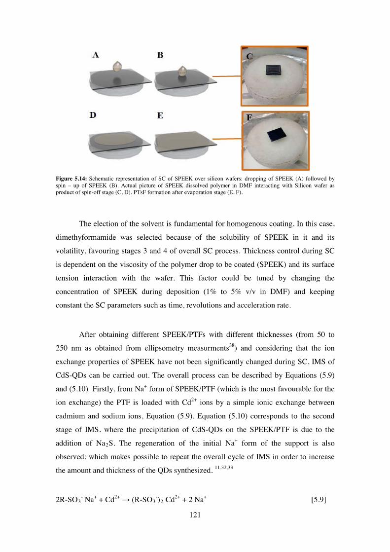
Figure 5.14: Schematic representation of SC of SPEEK over silicon wafers: dropping of SPEEK (A) followed by spin – up of SPEEK (B). Actual picture of SPEEK dissolved polymer in DMF interacting with Silicon wafer as product of spin-off stage (C, D). PTsF formation after evaporation stage (E, F).
The election of the solvent is fundamental for homogenous coating. In this case,
dimethyformamide was selected because of the solubility of SPEEK in it and its
volatility, favouring stages 3 and 4 of overall SC process. Thickness control during SC
is dependent on the viscosity of the polymer drop to be coated (SPEEK) and its surface
tension interaction with the wafer. This factor could be tuned by changing the
concentration of SPEEK during deposition (1% to 5% v/v in DMF) and keeping
constant the SC parameters such as time, revolutions and acceleration rate.
After obtaining different SPEEK/PTFs with different thicknesses (from 50 to
250 nm as obtained from ellipsometry measurments38) and considering that the ion
exchange properties of SPEEK have not been significantly changed during SC, IMS of
CdS-QDs can be carried out. The overall process can be described by Equations (5.9)
and (5.10) Firstly, from Na+ form of SPEEK/PTF (which is the most favourable for the
ion exchange) the PTF is loaded with Cd2+ ions by a simple ionic exchange between
cadmium and sodium ions, Equation (5.9). Equation (5.10) corresponds to the second
stage of IMS, where the precipitation of CdS-QDs on the SPEEK/PTF is due to the
addition of Na2S. The regeneration of the initial Na+ form of the support is also
observed; which makes possible to repeat the overall cycle of IMS in order to increase
the amount and thickness of the QDs synthesized. 11,32,33
2R-SO3- Na+ + Cd2+ → (R-SO3
-)2 Cd2+ + 2 Na+ [5.9]
121

(R-SO3-)2 Cd2+ + Na2S → 2R-SO3
- Na+ + CdS-QDs↓ [5.10]
The surface modification of SPEEK/PTF is shown in Figure 5.15. Figure 5.15B
shows a (S)TEM pi cture of C dS-QDs (white dot s) a nd t he E nergy D ispersive X -Ray
(EDS) o f Figure 5.15C is a qua litative pr oof of t he pr esence of t he C d a nd S i n the
sample. The s ize di stribution of t he Q Ds on t he SPEEK/PTF was de termined of HR-
TEM i mages ( 5.15D an d 5.15E) f rom w hich a size di stribution of ( 3.4 ± 0.3 nm ) i s
obtained.
Electron m icroscopy i mages an d E DS analysis evidence t hat IMS i s a v alid
technique for the synthesis of CdS-QDs in 2D polymeric supports such as SPEEK/PTFs
prepared b y S C. In a ddition, Q Ds size d istribution w as s imilar to o ther F MNPs
synthesized by IMS on SPEEK 3D films.23
Figure 5.15: A) Schematic representation of IMS of CdS-QDs on SPEEK PTFs. B) (S )TEM p icture o f CdS-QDs with their corresponding EDS on C. D) HR-TEM image and size distribution histogram of QDs (E).
122

5.2.3 Intermatrix Synthesis of CdS-QDs on Nanodiamonds (CdS-QDs@NDs)
NDs are less toxic nano carbon forms compared with MWCNTs. Their
feasibility of applications due to their biocompatibility and high temperature resistant,
make them an interesting matrix for the development of new low-dimensional carbon
nanomaterials.39–41
NDs usually present diameters from 4 to 5 nm and tend to agglomerate39
Experimental characterization of raw NDs showed a size distribution value of 3.5 ± 0.3
nm. Agglomerates can be avoided by ultrasonication of the sample before TEM analysis
(see Figure 5.16).
Figure 5.16: HR-TEM images of NDs (A,B magnification B>>>A) and raw NDs size distribution histogram(C).
The acidic treatment of the NDs leads to the appearance of carboxylic groups on
their surface. Consequently, the activated NDs represent an analogous form of
carboxylic polymers (eg. carboxylic resins and fibres) in which IMS was successfully
applied for the preparation of FMNPs.14,42
IMS has never been used before for the surface modification of 0 D supports as
NDs. Even though; as it is based on the ion exchange functionality of the support; the
IMS of CdS-QDs on NDs procedure proposed is described by Equations (5.11) and
(5.12).
123
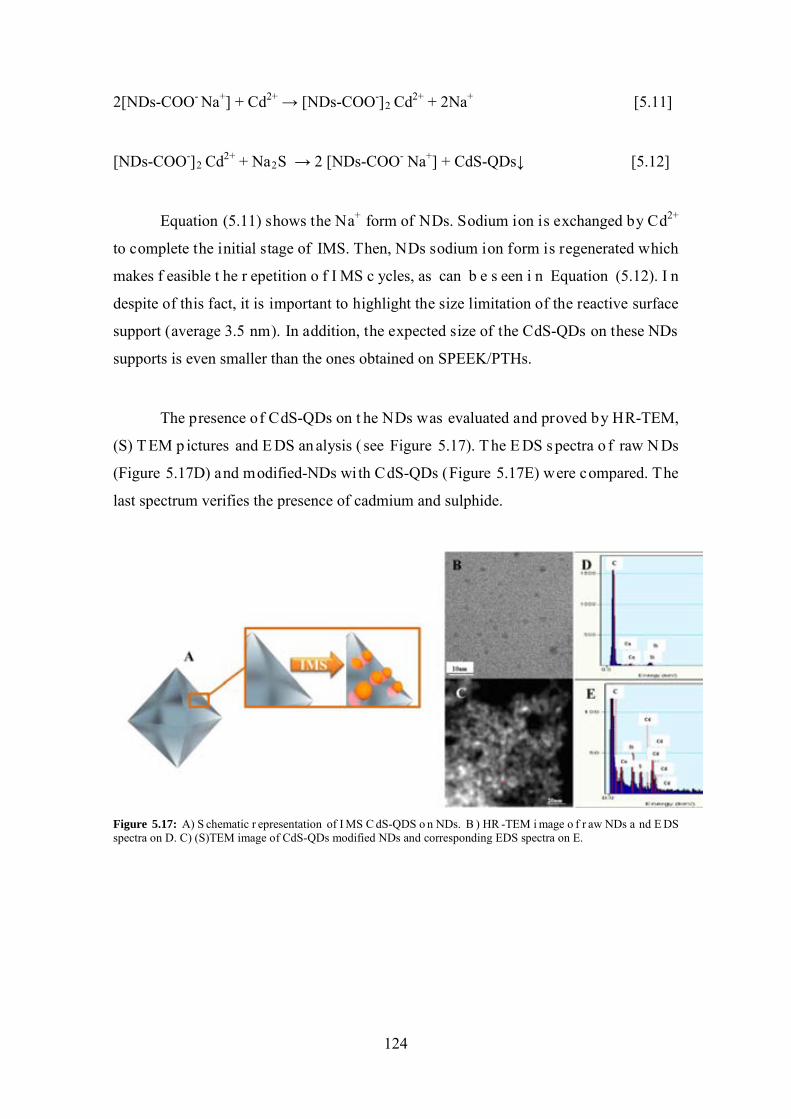
2[NDs-COO- Na+] + Cd2+ → [NDs-COO-]2 Cd2+ + 2Na+ [5.11]
[NDs-COO-]2 Cd2+ + Na2S → 2 [NDs-COO- Na+] + CdS-QDs↓ [5.12]
Equation (5.11) shows the Na+ form of NDs. Sodium ion is exchanged by Cd2+
to complete the initial stage of IMS. Then, NDs sodium ion form is regenerated which
makes f easible t he r epetition o f I MS c ycles, as can b e s een i n Equation (5.12). I n
despite of this fact, it is important to highlight the size limitation of the reactive surface
support (average 3.5 nm). In addition, the expected size of the CdS-QDs on these NDs
supports is even smaller than the ones obtained on SPEEK/PTHs.
The presence of CdS-QDs on t he NDs was evaluated and proved by HR-TEM,
(S) T EM p ictures and E DS an alysis ( see Figure 5.17). T he E DS s pectra o f raw N Ds
(Figure 5.17D) and modified-NDs wi th CdS-QDs (Figure 5.17E) were compared. The
last spectrum verifies the presence of cadmium and sulphide.
Figure 5.17: A) S chematic r epresentation of I MS C dS-QDS o n NDs. B ) HR -TEM i mage o f r aw NDs a nd E DS spectra on D. C) (S)TEM image of CdS-QDs modified NDs and corresponding EDS spectra on E.
124
5.2.4 Concluding Remarks:
IMS d emonstrates to b e a valid route for the p reparation o f multi-dimensional
Nanocomposite m aterials ( from 0 D s uch a s NDs t o 3 D as gr anulated e xchange
polymers) by the modification of di fferent t ypes of reactive surfaces with FMNPs. It
can be concluded that IMS is a non-aggressive and environmentally friendly technique,
applicable for t he functionalization of MWCNTs, NDs and PTFs with CdS-QDs wi th
favourable distribution as shown in electron microscopy characterization.
References:
(1) Adams, C. Applied Catalysis: A Predictive Socioeconomic History. Top. Catal. 2009, 52, 924–934.
(2) Van Hove, M. a. From Surface Science to Nanotechnology. Catal. Today 2006, 113, 133–140.
(3) Wang, Z.; Chen, G.; Ding, K. Self-Supported Catalysts. Chem. Rev. 2009, 109, 322–359.
(4) Centi, G.; Perathoner, S. Novel Catalyst Design for Multiphase Reactions. Catal. Today 2003, 79-80, 3–13.
(5) Biffis, A .; Z ecca, M .; Basato, M . P alladium Metal C atalysts in H eck C C Coupling Reactions. J. Mol. Catal. A Chem. 2001, 173, 249–274.
(6) Sullivan, J. a .; F lanagan, K . a .; H ain, H . S uzuki C oupling A ctivity of a n Aqueous P hase P d N anoparticle D ispersion a nd a C arbon na notube/Pd N anoparticle Composite. Catal. Today 2009, 145, 108–113.
(7) Batail, N.; Genelot, M.; Dufaud, V.; Joucla, L.; Djakovitch, L. Palladium-Based Innovative C atalytic P rocedures: D esigning N ew H omogeneous a nd H eterogeneous Catalysts f or t he S ynthesis a nd F unctionalisation of N -Containing H eteroaromatic Compounds. Catal. Today 2011.
(8) Najar, H.; Saïd Zina, M.; Ghorbel, a. Catalytic Activity of Palladium Supported on M esoporous M odified Y -Zeolite i n M ethane C ombustion. Kinet. Catal. 2010, 51, 602–608.
(9) Polshettiwar, V .; Luque, R .; F ihri, A .; Z hu, H .; Bouhrara, M .; B asset, J.-M. Magnetically Recoverable Nanocatalysts. Chem. Rev. 2011.
125

(10) Kung, H . H .; K ung, M . C . N anotechnology: A pplications a nd P otentials f or Heterogeneous Catalysis. Catal. Today 2004, 97, 219–224.
(11) Ruiz, P .; M uñoz, M .; Macanás, J.; T urta, C .; P rodius, D .; M uraviev, D . N . Intermatrix S ynthesis o f P olymer S tabilized Inorganic N anocatalyst w ith M aximum Accessibility for Reactants. Dalton Trans. 2010, 39, 1751–1757.
(12) Muraviev, D . N . Inter-Matrix S ynthesis o f P olymer S tabilised M etal Nanoparticles for Sensor Applications. Contrib. to Sci. 2005, 3, 19–32.
(13) Muraviev, D . N.; R uiz, P .; M uñoz, M .; M acanás, J . N ovel S trategies f or Preparation a nd C haracterization of F unctional P olymer-Metal N anocomposites f or Electrochemical Applications. Pure Appl. Chem. 2008, 80, 2425–2437.
(14) Alonso, A .; M acanás, J .; S hafir, A .; M uñoz, M .; V allribera, A .; P rodius, D .; Melnic, S .; T urta, C .; Muraviev, D . N . D onnan-Exclusion-Driven D istribution of Catalytic Ferromagnetic Nanoparticles Synthesized in Polymeric Fibers. Dalton Trans. 2010, 39, 2579–2586.
(15) Witten, T . A .; Sander, L . M . D iffussion-Limited A ggregation. Phys. Rev. B 1983, 27, 5686–5697.
(16) ROTHSCHILD, W . G . Fractals i n Heterogeneous C atalysis. Catal. Rev. Sci. Eng. 33, 71–107.
(17) Romeu, D.; Gómez, a; Ramírez, J.; Silva, R.; Pérez, O.; González, A.; Yacamán, M. S urface F ractal D imension o f S mall M etallic P articles. Phys. Rev. Lett. 1986, 57, 2552–2555.
(18) Sander, L.; Ghaisas, S. Fractals and Patterns in Catalysis. Phys. A Stat. Mech. its Appl. 1996, 233, 629–639.
(19) Alonso, A .; V igués, N .; M uñoz-Berbel, X .; M acanás, J .; M uñoz, M .; M as, J .; Muraviev, D . N. Environmentally-Safe B imetallic Ag@Co Magnetic Nanocomposites with Antimicrobial Activity. Chem. Commun. (Camb). 2011, 47, 10464–10466.
(20) Alonso, A .; B astos-arrieta, J .; D avies, G . L .; G un, Y . K .; V igués, N .; M uñoz-berbel, X .; M acanás, J .; M as, J .; M uñoz, M .; Muraviev, D . N . E cologically F riendly Polymer-Metal an d P olymer- Metal O xide N anocomposites f or C omplex W ater Treatment.
(21) Alonso, A.; Muñoz-Berbel, X.; Vigués, N.; Rodríguez-Rodríguez, R.; Macanás, J.; M as, J.; M uñoz, M .; M uraviev, D . N . Intermatrix S ynthesis of M onometallic an d Magnetic M etal/metal Oxide N anoparticles w ith B actericidal A ctivity o n A nionic Exchange Polymers. RSC Adv. 2012, 2, 4596–4599.
(22) Domènech, B .; M uñoz, M .; M uraviev, D . N .; M acanás, J . P olymer-Stabilized Palladium N anoparticles f or C atalytic M embranes: A d H oc P olymer F abrication. Nanoscale Res. Lett. 2011, 6, 406.
126

(23) Ruiz, P .; M uñoz, M .; Macanás, J .; M uraviev, D . N . Intermatrix S ynthesis of Polymer−Copper Nanocomposites with Tunable Parameters by Using Copper Comproportionation Reaction. Chem. Mater. 2010, 22, 6616–6623.
(24) Domènech, B.; Muñoz, M.; Muraviev, D. N.; Macanás, J . Uncommon Patterns in Nafion Films Loaded with Silver Nanoparticles. Chem. Commun. (Camb). 2014, 50, 4693–4695.
(25) Muñoz, J.; Bastos-Arrieta, J.; Munoz, M.; Muraviev, D. N.; Céspedes, F.; Baeza, M. S imple G reen R outes f or t he C ustomized P reparation of S ensitive C arbon Nanotubes/epoxy Nanocomposite Electrodes with Functional Metal Nanoparticles. RSC Adv. 2014.
(26) Elliott, S. D.; Moloney, M. P.; Gun’ko, Y. K. Chiral Shells and Achiral Cores in CdS Quantum Dots. Nano Lett. 2008, 8, 2452–2457.
(27) Petryayeva, E .; A lgar, W. R .; M edintz, I . L. Q uantum D ots i n B ioanalysis: A Review of A pplications a cross V arious P latforms f or F luorescence S pectroscopy and Imaging. Appl. Spectrosc. 2013, 67, 215–252.
(28) Moloney, M. P .; Gun’ko, Y . K .; Kelly, J . M. Chiral H ighly Luminescent CdS Quantum Dots. Chem. Commun. (Camb). 2007, 7345, 3900–3902.
(29) Bera, D .; Qian, L.; T seng, T .-K.; H olloway, P . H . Q uantum D ots and T heir Multimodal Applications: A Review. Materials (Basel). 2010, 3, 2260–2345.
(30) Ruiz, P.; Macanás, J.; Muñoz, M.; Muraviev, D. N. Intermatrix Synthesis: Easy Technique P ermitting P reparation of P olymer-Stabilized N anoparticles with D esired Composition and Structure. Nanoscale Res. Lett. 2011, 6, 343.
(31) Son, J. S.; Park, K.; Kwon, S. G.; Yang, J.; Choi, M. K.; Kim, J.; Yu, J. H.; Joo, J.; Hyeon, T. Dimension-Controlled Synthesis of CdS Nanocrystals: From 0D Quantum Dots to 2D Nanoplates. Small 2012, 8, 2394–2402.
(32) Muraviev, D . N .; M acanás, J .; Ruiz, P .; M uñoz, M . S ynthesis, S tability and Electrocatalytic A ctivity o f Polymer-Stabilized Monometallic P t and B imetallic P t/Cu Core-Shell Nanoparticles. Phys. Status Solidi 2008, 205, 1460–1464.
(33) Muraviev, D.; Macanas, J.; Farre, M.; Munoz, M.; Alegret, S. Novel Routes for Inter-Matrix Synthesis and Characterization of Polymer Stabilized Metal Nanoparticles for Molecular Recognition Devices. Sensors Actuators B Chem. 2006, 118, 408–417.
(34) Chou, K.-S.; Huang, K.-C.; Lee, H.-H. Fabrication and S intering Effect on the Morphologies a nd C onductivity of N ano-Ag Particle F ilms b y the Spin C oating Method. Nanotechnology 2005, 16, 779–784.
(35) Decher, G.; Schlenoff, J. B. Multilayer Thin Films. 2012.
(36) Sahu, N.; Parija, B.; Panigrahi, S. Fundamental Understanding and Modeling of Spin Coating Process: A Review. Indian J. Phys. 2009, 83, 493–502.
127
(37) Höcker, H. P lasma T reatment o f T extile F ibers. Pure Appl. Chem. 2002, 74, 423–427.
(38) Redel, E.; Mirtchev, P.; Huai, C.; Petrov, S.; Ozin, G. a. Nanoparticle Films and Photonic Crystal Multilayers f rom Colloidally Stable, Size-Controllable Zinc and Iron Oxide Nanoparticles. ACS Nano 2011, 5, 2861–2869.
(39) Mochalin, V . N .; S henderova, O .; H o, D .; G ogotsi, Y . T he P roperties a nd Applications of Nanodiamonds. Nat. Nanotechnol. 2012, 7, 11–23.
(40) Purtov, K . V ; P etunin, a I.; B urov, a E .; Puzyr, a P .; B ondar, V. S . Nanodiamonds a s C arriers f or A ddress D elivery of B iologically Active S ubstances. Nanoscale Res. Lett. 2010, 5, 631–636.
(41) Fu, C.-C.; Lee, H.-Y.; Chen, K.; Lim, T.-S.; Wu, H.-Y.; Lin, P.-K.; Wei, P.-K.; Tsao, P .-H.; C hang, H .-C.; F ann, W . Characterization a nd A pplication of S ingle Fluorescent N anodiamonds a s C ellular B iomarkers. Proc. Natl. Acad. Sci. U. S. A. 2007, 104, 727–732.
(42) Alonso, A .; M uñoz-Berbel, X .; V igués, N.; M acanás, J.; M uñoz, M .; M as, J .; Muraviev, D. N. Characterization of Fibrous Polymer Silver/cobalt Nanocomposite with Enhanced Bactericide Activity. Langmuir 2012, 28, 783–790.
128

“The journey is the reward”
-Steve Jobs-

Conclusions
6. Conclusions
This s ection s ummarizes t he pr incipal c onclusive r esults obt ained t hrough t he
development of this PhD Thesis, focused on the application of the Intermatrix Synthesis
Technique coupled with the Donnan Exclusion Effect (DEEIMS) as green methodology
for the preparation of different bifunctional nanocomposites (BFNCs). The main aim of
the P hD r esearch i ncluded s urface m odification o f reactive m atrices with f unctional
metal na noparticles (FMNPs) b y di fferent D EEIMS r outes, t he e valuation of t he
properties of the BFNCs and looking for feasible applications for them
For t he r esearch ba sed on B FNCs c ontaining FMNPs, pa rticular e mphasis ha s
been devoted to modifying nanoparticle surface chemistry, size, and shape to tailor the
thermodynamic driving forces in the assembly process. Fundamental understanding of
the r ole of t he i on e xchange, r educing agents, metal p recursors a nd th e ma trix its elf;
have be en t aken i nto a ccount a nd de scribed a s t he c haracterization of BFNCs allows
concluding information ,
In addition, r ecent de velopments i n D EEIMS e xposed i n t his t hesis l ead t he
preparation of different kind of nanocrystals such as quantum dots (QDs) and FMNPs;
with a wide range of compositions and geometries, with future feasible approaches and
applications, since is been proved that the main requirement for the application of this
environmentally f riendly t echnique, i s t o f ind a r eactive s urface i n terms o f i on
exchange functionality.
The generation of results presented in this Thesis, included some general stages through
the design of the optimized preparation of BFNCs:
a) Understanding and opt imizing D EEIMS f or c ustomized pr eparation of
BFNCs:
b) Understanding t he s urface changes a nd t he i mpact on i on e xchange
properties of the reactive surfaces due to DEEIMS.
c) Enhancing the performance of the BFNCs for specific applications.
d) Designing further approaches of DEEIMS: novel matrices.
130
Consequently, specific conclusions obtained are listed below
1) DEEIMS can be considered as a valid technique for modification of both anionic
and c ationic e xchangers. B oth pr imary i on e xchange s tages ( loading t he N Ps
precursors and r eduction) can b e ap plied i n t he “cl assical” o r “symmetrical”
version depending on the surface to be modified with NPS.
2) The loading stage of DEEIMS for both anionic and cationic exchangers proved
to be efficient due to the previous adequacy of the reactive matrix with a more
suitable io nic f orm: N a-form f or c ationic e xchangers a nd C l-form anionic
exchangers. This means that the ion exchange process and incorporation of the
FMNPs precursors is more favourable; obtaining loading exchange efficiencies
up to 85% in average.
3) The dr iven f orce o f t he customized di stribution of t he F MNPS i n t he BFNCs
was proved to be DEE. Depending of the charge of the functional groups of the
reactive matrix and the ionic charge of the reducing agent, DEEIMS leads to the
customized s patial d istribution o f FMNPs in t he BFNCs. T herefore, i onic
reducing ag ents ( NaBH4 and A scorbic A cid) allow obt aining BFNCs with
FMNPs mainly located on the surface of polymer for both anionic and cationic
exchangers. On the contrary; when using neutral reducing agents (such as, e.g.
formaldehyde) t he di stribution of F MNPs a ppears t o be hom ogeneous
throughout the volume of BFNC.
4) The s ize di stribution of FMNPs ha s be en s hown t o be t he r esult of r educing
reduction stage of DEEIMS, more specifically of the reduction agent strength. It
has be en v erified t hat t he us e of a s trong r educing a gent s uch as N aBH4 in
DEEIMS leads to formation of smaller NPs than when a “softer” reducing agent
such a s A A i s us ed, m ainly du e t o c hange o f the nuc leation r ate du ring t he
reduction stage for both ion-exchange systems.
5) The s econd s tage of D EEIMS ( NPs f ormation) can be m odified b y us ing t he
precipitation reaction instead of the reduction one by substituting the reduction
agent with the p recipitation one . B y us ing this version of DEEIMS technique
the synthesis of CdS-QDs on a gel-type cation-exchange polymer was achieved,
with a f avourable di stribution of t he Q Ds m ainly on t he s urface of t he m atrix
131
and w ith h igh efficiency of th e lo ading s tage. T his is th e f irst time in our
research gr oup t hat Q Ds w ere pr epared b y using D EEIMS. D ue t o t heir
interesting properties, simple green methodologies for the preparation of BFNCs
containing Q Ds, c an be c onsidered a s a n ew pr iority for t heir further
applications.
6) By controlling the concentration of the reducing agent, its reduction power and
the addition rate, DEEIMS becomes a suitable technique for the preparation of
controlled–shape na nostructures, s uch a s e.g. A g-cubic n ano- and
microstructures. E lectron m icroscopy ch aracterization a nd m etal c ontent
analysis verified the chemical identity of these structures. Accordingly with the
spatial distribution advantage offered by DEEIMS for NPs, it is conserved when
these Ag-cubic structures are prepared.
7) The g alvanic d isplacement s tage carried o ut af ter D EEIMS represents a n ew
approach applicable for preparation of BFNCs. It is important to emphasize that
by t his e xtended a pproach, t he D EEIMS of A u-NPs o n cat ionic ex changers i s
possible w hen a s uitable g alvanic r eplacement p air i s s elected. T his m eans, t o
use DEEIMS for the preparation of low cost “sacrificial” NPs (such as Cu) and
then to carry out a galvanic replacement stage with a more valuable metal as Au.
The efficiency of galvanic replacement coupled with DEEIMS has proved to be
almost 100%.
8) Regarding the extension of DEEIMS with galvanic replacement, the preparation
of A gAu bi metallic c ubic s tructures c an b e pr epared us ing pr eviously
synthesized Ag-cubic structures as templates. The spatial profile distribution of
AgAu in the hybrid structures and the electron microscopy characterization have
shown that t hese s tructures t end t o be hol low. This can b e ex plained by the
Kirkendall Effect during the galvanic replacement stage; in which the diffusion
of A u i s s lower t han the A g. The t uned pr eparation of t hese hol low h ybrid
structures opens a brand new research field due to this extension of DEEIMS.
9) iDEEIMS of Ag-MNPs on cationic gel-type polymers induces the appearance of
nanoporosity i n t he BFNCs. This improves t he mass-transfer characteristics o f
132

the m atrix w hat i s pa rticularly i mportant f or c arrying out t he i on e xchange
processes o n t hese m aterials. These changes c an b e ex plained d ue t o t he
localization o f th e A g-NPs m ainly i n t he s urface of t he m atrix i n w hich t he
interaction with the polymeric changes leads to the increase of the cross-linking
degree an d t herefore t he ap pearance o f t he “worm-like” s tructures on t he
polymer surface.
10) Evaluation of the ion exchange properties of BFNCs with surface morphological
changes before and after DEEIMS, shows that the ion exchange capacity of the
polymer i s not e ssentially changed a fter i ts m odification w ith F MNP a nd t he
morphological c hanges obs erved. It i s ve rified b y t he br eakthrough c urve
profiles obtained on the unmodified matrix and modified with Ag-FMNPs. As it
also follows from these data, the resistance of the matrix towards ions diffusion
can be minimized by varying the thickness of FMNPs layer and it can reach the
same value as that of the unmodified polymer.
11) It is d emonstrated th at DEEIMS i s a lso s uitable f or t he pr eparation of
heterogeneous nanocatalysts with the most favorable distribution of nanocatalyst
NPs, such as Pd-NPs containing BFNCs. The catalytic activity of these BFNCs
was checked in the Suzuki and proved to be effective and recyclable.
12) The a pplication of DEEIMS do es not d epend o n t he s cale o f t he s upporting
reactive surface but just on its ion exchange functionality. Considering this fact,
it ha s be en s hown t he f easibility of D EEIMS a pplication f or m odification of
other nove l r eactive matrices s uch as c arbon na notubes ( CNTs) a nd
nanodiamonds (NDs).
13) The c lassic ve rsion of D EEIMS w as c arried out on C NTs to obt ain d ifferent
noble metal NPs, due to the carboxylic functionality of this support. Moreover,
the extension of DEEIMS with ga lvanic r eplacement was used as w ell f or t he
preparation of Au-NPs on the CNTs. The final application of these BFNCs is for
the en hancement o f electrochemical s ensors r esponse t o s pecific analytes. In
addition, a DEEIMS-precipitation technique was carried out on C NTs to obtain
CdS-QDs.
133
14) DEEIMS de monstrates t o be a va lid r oute for t he pr eparation of m ulti-
dimensional (from 0 D to 3 D) BFNCs (by the modification of different types of
reactive s urfaces w ith F MNPs. It c an be c oncluded t hat D EEIMS i s a non -
aggressive a nd e nvironmentally f riendly t echnique, a pplicable f or t he
functionalization of C NTs, N anodiamonds ( NDs) w ith Q Ds w ith f avourable
distribution.
The main conclusion of these PhD thesis, is that DEEIMS demonstrated to be an
effective synthetic methodology suitable for the preparation BFNCs in reactive surfaces
of ei ther f unctionality, i .e. be aring e ither ne gatively ( e.g., c ation e xchangers) or
positively (e.g., anion exchangers) charged functional groups. It was proved the feasible
application of DEEIMS for the modification of novel matrices such as nanodiamodonds
with FMNPs. In further research, the modification of novel interesting reactive surfaces
such as graphene may be accomplished by the optimization of the process and adequacy
of the matrix.
134

Annexes

ANNEX 1
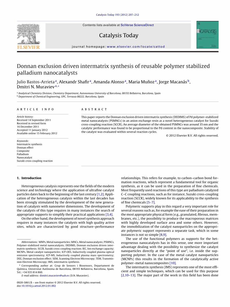
Dp
JDa
b
a
ARR1AA
KIDCPNS
1
spcbtta
rs
PmMeDs
QT
0d
Catalysis Today 193 (2012) 207– 212
Contents lists available at SciVerse ScienceDirect
Catalysis Today
jou rn al h om epage: www.elsev ier .com/ locate /ca t tod
onnan exclusion driven intermatrix synthesis of reusable polymer stabilizedalladium nanocatalysts
ulio Bastos-Arrietaa, Alexandr Shafira, Amanda Alonsoa, Maria Munoza, Jorge Macanásb,mitri N. Muravieva,∗
Analytical Chemistry Division, Chemistry Department, Autonomous University of Barcelona, 08193 Bellaterra, Barcelona, SpainDepartment of Chemical Engineering, UPC, Terrassa 08222, Barcelona, Spain
r t i c l e i n f o
rticle history:eceived 14 September 2011eceived in revised form6 December 2011ccepted 11 January 2012vailable online 15 February 2012
a b s t r a c t
This paper reports the Donnan exclusion driven intermatrix synthesis (DEDIMS) of Pd polymer-stabilizedmetal nanocatalysts (PSMNCs) in an anion exchange resin as a novel heterogeneous catalyst for Suzukicross-coupling reaction (SCCR). An average diameter of the obtained PSMNCs was around 35 nm and thecatalytic performance was found to be proportional to the Pd content in the nanocomposite. Stability ofthe catalyst was evaluated within several reaction cycles.
© 2012 Elsevier B.V. All rights reserved.
eywords:ntermatrix synthesisonnan effectompositealladiumanocatalyst
uzuki cross coupling reaction. Introduction
Heterogeneous catalysis represents one the fields of the moderncience and technology where the application of ultrafine catalystarticles dates back to the beginning of the last century [1,2]. Appli-ation of the heterogeneous catalysis within the last decades haseen strongly stimulated by the development of the new genera-ion of catalysts with nanometer dimensions. The development ofhe catalysts of this type requires in many instances the search ofppropriate supports to simplify their practical applications [3,4].
On the other hand, the development of novel synthesis approachequires in many instances the catalysts with high quality activeites, which are characterized by good structure–performance
Abbreviations: MNPs, Metal nanoparticles; MNCs, Metal nanocatalysts; PSMNCs,olymer-stabilized metal nanocatalysts; DEDIMS, Donnan exclusion driven inter-atrix synthesis; SCCR, Suzuki cross-coupling reaction; IEC, Ion exchange capacity;CNPs, Metal catalyst nanoparticles; ICP-OES, Inductively coupled plasma optical
mission spectrometry; ICP-MS, Inductively coupled plasma mass spectrometry;EE, Donnan exclusion effect; SEM, Scanning Electron Microscopy; TEM, Transmis-
ion Electron Microscopy; IMS, intermatrix synthesis.∗ Corresponding author at: Grup de Sensors i Biosensors, Departament deuímica, Universitat Autònoma de Barcelona, 08193 Bellaterra, Barcelona, Spain.el.: +34 935 814 860.
E-mail address: [email protected] (D.N. Muraviev).
920-5861/$ – see front matter © 2012 Elsevier B.V. All rights reserved.oi:10.1016/j.cattod.2012.01.002
relationships. This refers for example, to carbon–carbon bond for-mation reactions, which represent a fundamental tool for organicsynthesis, as it can be used in the preparation of fine chemicals.Most frequently used reactions of this type are palladium catalyzedC–C coupling reactions, such as for instance, Suzuki cross-couplingreaction (SCCR), widely known for its applicability to the synthesisof fine chemicals [5–7].
Polymeric supports play in this regard a very important role forseveral reasons such as, for example the ease of their preparation inthe most appropriate physical form (e.g., granulated, fibrous, mem-branes, etc.), the possibility to produce the macroporous matriceswith highly developed surface area and some others. However,the immobilization of the catalyst nanoparticles on the appropri-ate polymeric support represents a separate task, which in someinstances is not so simple [8,9].
The use of the functional polymers as supports for the het-erogeneous nanocatalysts has in this sense, one more importantadvantage dealing with the possibility to synthesize the catalystnanoparticles directly at the “point of use”, i.e. inside the sup-porting polymer. In the case of the metal catalyst nanoparticles(MCNPs) this results in the formation of the catalytically active
polymer–metal nanocomposites [10].The intermatrix synthesis (IMS) represents one of the most effi-cient and simple techniques, which can be used for this purpose[2,10–13]. The major part of the work in this field has been done

2 lysis Today 193 (2012) 207– 212
w(tlatdc“[
useirm
t(cpat
2
2
Gsr
awNt
2
fumliIdp
2
PoParw1
2
i
08 J. Bastos-Arrieta et al. / Cata
ith the polymers bearing negatively charged functional groupscation exchange membranes, resins or fibers), which first haveo be loaded with the desired metal ions (MCNPs precursors) fol-owed by their reduction to zero-valent state (MCNPs) by using anppropriate reducing agent [10–17]. Several recent publications byhe authors describe the IMS of MCNPs with the most favorableistribution near the surface of nanocomposite for catalytic appli-ations [3,10]. This version of IMS is based on the coupling of theclassic” version of IMS technique with the Donnan exclusion effect8–11].
In general, the desired distribution of MCNPs is achieved bysing the ionic reducing agents bearing the charge of the sameign as that of the polymeric matrix [18–26]. The action of Donnanxclusion does not allow for the deep penetration of the reducerons inside the polymer loaded with metal ions. As the result, theireduction proceeds mainly in the surface part of the polymericatrix [21].This communication reports the results obtained by the fur-
her development of the Donnan effect driven intermatrix synthesisDEDIMS) technique by its extension to the polymers, which matri-es bear the positively charged functional groups (anion exchangeolymers or resins). The version of DEDIMS technique, which ispplied in this case, can be considered as the “symmetrical reflec-ion” of the previously developed DEDIMS method.
. Materials and methods
.1. Reagents and materials
Metal salts as Pd(NH3)4Cl2·H2O, and NaBH4 (all from Aldrich,ermany), mineral acids and organic compounds for SCCR andolvents (all from Panreac, S.A. Spain) of p.a. grade were used aseceived. Bidistilled water was used in all experiments.
A portion of granulated Purolite A520E resin of known weightnd granule size (∼0.5 mm in diameter) was washed by bidistilledater and then dried at 80 C for 24 h. The resin was then stirred inaOH 1 M solution for 6 h to convert it from Cl- to OH-form. Finally
he polymer was dried at 80 C for 24 h.
.2. Intermatrix synthesis of Pd-PSMNCs
The IMS of Pd-PSMNCs was carried out by the loading of theunctional groups of the polymer with reducing agent anions bysing 20 mL of 0.1 M aqueous NaBH4 solution followed by the treat-ent of the resin with 10 mL of 0.01 M Pd(NH3)4Cl2 solution. The
ast stage resulted in the formation of polymer–metal nanocompos-te containing Pd-PSMNCs. Some of the working parameters of theMS procedure (such as Pd concentration and the experimental con-itions will be detailed in each experiment. This is the symmetricrocess of the usual performed in the group research.
.3. Determination of ion exchange capacity (IEC) of resin
The IEC of the polymer was checked before and after IMS ofd-PSMNCs by using the following procedure: several samplesf around 200 mg of Purolite A520E resin with or without Pd-SMNCs were immersed in aliquots of 25 mL of 0.0059 M Na2CO3nd stirred for 4 h. Then aliquots of 20 mL were taken from theesulting solution for titration with HCl 0.0477 M. The IEC valuesere calculated from the titration results and appeared to equal
.22 ± 0.04 meq/gresin before and after IMS of Pd-PSMNCs.
.4. Analysis of nanocomposite composition
A sample of around 10 mg of PSMNCs-containing material wasmmersed in 1 mL of aqua regia to completely dissolve palladium
Scheme 1. Schematic diagram of Suzuki cross-coupling reaction.
by oxidation. The obtained solution was filtrated through a 0.22 mMillipore filter and adequately diluted for metal content quantifica-tion by Inductively Coupled Plasma Optical Emission Spectrometry,ICP–OES (Iris Intrepid II XSP spectrometer from Thermo ElectronCo.) and Inductively Coupled Plasma Mass Spectroscopy, ICP-MS(Agilent 7500). An average uncertainty of metal ions determinationwas in all cases lower than 2%.
2.5. SEM and TEM characterization
Scanning Electron Microscopes (SEM) coupled with an Energy-Dispersive Spectrometer (EDS) Zeiss EVO MA 10 and Zeiss MERLINFE-SEM and Transmission Electron Microscope (TEM) studies werecarried out by using JEOL 2011 and JEOL 1400 microscopes (all fromServei de Microscòpia of Universitat Autònoma de Barcelona). SEMand TEM techniques were used to obtain the metal concentrationprofiles along the cross-section of the PSMNC-containing materi-als, morphology of the polymer surface and for determination ofMNPs diameter distribution histograms. The nanocomposite sam-ples were prepared by embedment of several granules in an epoxyresin followed by cutting and cross-sectioning with Leica EM UC6ultramicrotome using a 35 diamond knife (Diatome) at the tem-perature of liquid nitrogen (−196 C).
2.6. Catalysis of Suzuki cross-coupling reaction
A known quantity of Pd-PSMNCs (corresponding to 1%molar rate of Pd to 4-bromoacetophenone) was mixed with4-bromoacetophenone 98% (1 mmol), phenylboronic acid 98%(1 mmol), K2CO3 (1 mmol) dissolved in the mixture of DMF–H2O(80:20) and stirred at 80 C for 18 h as it was settle as optimal exper-imental conditions for this reaction in previous works by using theanalogue cation exchanger as a matrix [15]. The conversion degreeand the efficiency rate of the reaction were followed by moni-toring by gas chromatography (7820A GC, Agilent Technologies)(Scheme 1).
3. Results
3.1. Traditional (classic) and novel versions of IMS technique
The difference between the “classical” and the novel version ofthe IMS technique developed in this study become clear after com-parison of the respective reaction schemes, which can be writtenfor the case of formation of Pd-MCNPs in the strong acid (a) and thestrong base (b) functional polymers as follows:
(a) IMS in cation exchange polymers (classical version):(1) Metal-loading stage
2R-COO—Na+ + [Pd(NH3)4]2+ →(R-COO−)2[Pd(NH3)4]2+ + 2Na+ (1)
(2) Metal-reduction stage
(R-COO−)2[Pd(NH3)4]2+ + 2NaBH4 + 6H2O →2R-SO3-Na+ + Pd0 + 7H2 + 2B(OH)3 + 4NH3. (2)
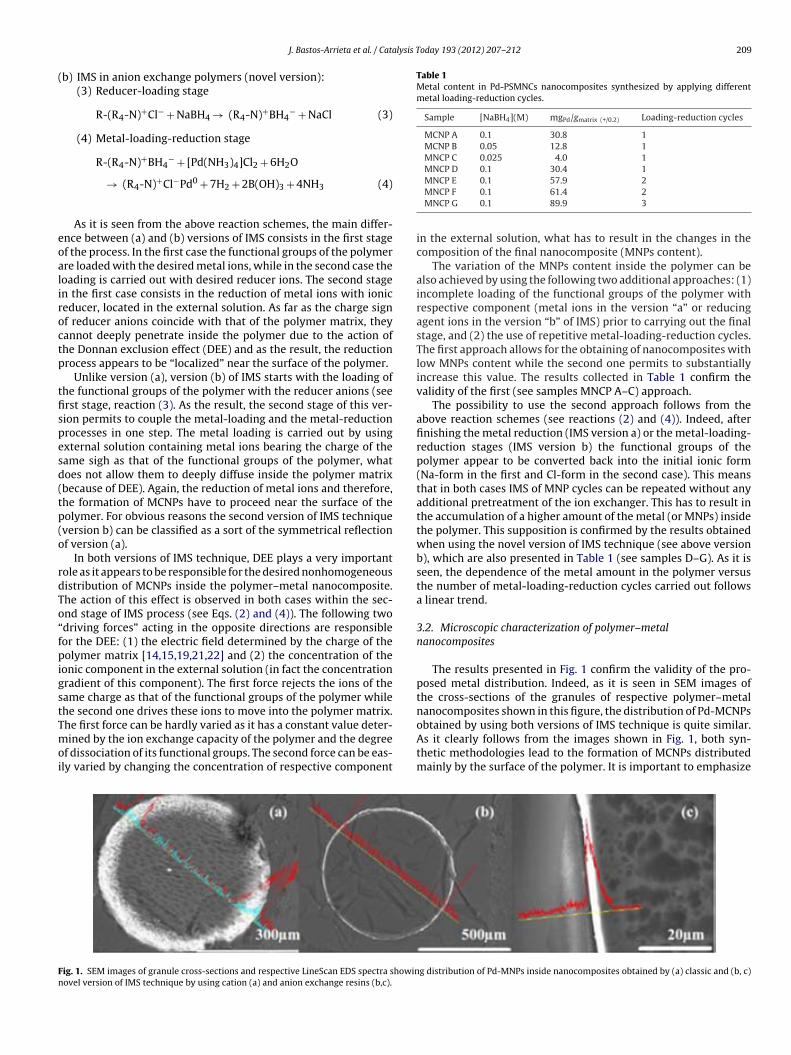
lysis Today 193 (2012) 207– 212 209
(
eoaliroctp
tfispesd(tp(o
rdTo“fpigstTmoi
Table 1Metal content in Pd-PSMNCs nanocomposites synthesized by applying differentmetal loading-reduction cycles.
Sample [NaBH4](M) mgPd/gmatrix (+/0.2) Loading-reduction cycles
MCNP A 0.1 30.8 1MCNP B 0.05 12.8 1MNCP C 0.025 4.0 1MNCP D 0.1 30.4 1
Fn
J. Bastos-Arrieta et al. / Cata
b) IMS in anion exchange polymers (novel version):(3) Reducer-loading stage
R-(R4-N)+Cl− + NaBH4 → (R4-N)+BH4− + NaCl (3)
(4) Metal-loading-reduction stage
R-(R4-N)+BH4− + [Pd(NH3)4]Cl2 + 6H2O
→ (R4-N)+Cl−Pd0 + 7H2 + 2B(OH)3 + 4NH3 (4)
As it is seen from the above reaction schemes, the main differ-nce between (a) and (b) versions of IMS consists in the first stagef the process. In the first case the functional groups of the polymerre loaded with the desired metal ions, while in the second case theoading is carried out with desired reducer ions. The second stagen the first case consists in the reduction of metal ions with ioniceducer, located in the external solution. As far as the charge signf reducer anions coincide with that of the polymer matrix, theyannot deeply penetrate inside the polymer due to the action ofhe Donnan exclusion effect (DEE) and as the result, the reductionrocess appears to be “localized” near the surface of the polymer.
Unlike version (a), version (b) of IMS starts with the loading ofhe functional groups of the polymer with the reducer anions (seerst stage, reaction (3). As the result, the second stage of this ver-ion permits to couple the metal-loading and the metal-reductionrocesses in one step. The metal loading is carried out by usingxternal solution containing metal ions bearing the charge of theame sigh as that of the functional groups of the polymer, whatoes not allow them to deeply diffuse inside the polymer matrixbecause of DEE). Again, the reduction of metal ions and therefore,he formation of MCNPs have to proceed near the surface of theolymer. For obvious reasons the second version of IMS techniqueversion b) can be classified as a sort of the symmetrical reflectionf version (a).
In both versions of IMS technique, DEE plays a very importantole as it appears to be responsible for the desired nonhomogeneousistribution of MCNPs inside the polymer–metal nanocomposite.he action of this effect is observed in both cases within the sec-nd stage of IMS process (see Eqs. (2) and (4)). The following twodriving forces” acting in the opposite directions are responsibleor the DEE: (1) the electric field determined by the charge of theolymer matrix [14,15,19,21,22] and (2) the concentration of the
onic component in the external solution (in fact the concentrationradient of this component). The first force rejects the ions of theame charge as that of the functional groups of the polymer whilehe second one drives these ions to move into the polymer matrix.
he first force can be hardly varied as it has a constant value deter-ined by the ion exchange capacity of the polymer and the degreef dissociation of its functional groups. The second force can be eas-ly varied by changing the concentration of respective component
ig. 1. SEM images of granule cross-sections and respective LineScan EDS spectra showinovel version of IMS technique by using cation (a) and anion exchange resins (b,c).
MNCP E 0.1 57.9 2MNCP F 0.1 61.4 2MNCP G 0.1 89.9 3
in the external solution, what has to result in the changes in thecomposition of the final nanocomposite (MNPs content).
The variation of the MNPs content inside the polymer can bealso achieved by using the following two additional approaches: (1)incomplete loading of the functional groups of the polymer withrespective component (metal ions in the version “a” or reducingagent ions in the version “b” of IMS) prior to carrying out the finalstage, and (2) the use of repetitive metal-loading-reduction cycles.The first approach allows for the obtaining of nanocomposites withlow MNPs content while the second one permits to substantiallyincrease this value. The results collected in Table 1 confirm thevalidity of the first (see samples MNCP A–C) approach.
The possibility to use the second approach follows from theabove reaction schemes (see reactions (2) and (4)). Indeed, afterfinishing the metal reduction (IMS version a) or the metal-loading-reduction stages (IMS version b) the functional groups of thepolymer appear to be converted back into the initial ionic form(Na-form in the first and Cl-form in the second case). This meansthat in both cases IMS of MNP cycles can be repeated without anyadditional pretreatment of the ion exchanger. This has to result inthe accumulation of a higher amount of the metal (or MNPs) insidethe polymer. This supposition is confirmed by the results obtainedwhen using the novel version of IMS technique (see above versionb), which are also presented in Table 1 (see samples D–G). As it isseen, the dependence of the metal amount in the polymer versusthe number of metal-loading-reduction cycles carried out followsa linear trend.
3.2. Microscopic characterization of polymer–metalnanocomposites
The results presented in Fig. 1 confirm the validity of the pro-posed metal distribution. Indeed, as it is seen in SEM images ofthe cross-sections of the granules of respective polymer–metalnanocomposites shown in this figure, the distribution of Pd-MCNPs
obtained by using both versions of IMS technique is quite similar.As it clearly follows from the images shown in Fig. 1, both syn-thetic methodologies lead to the formation of MCNPs distributedmainly by the surface of the polymer. It is important to emphasizeg distribution of Pd-MNPs inside nanocomposites obtained by (a) classic and (b, c)
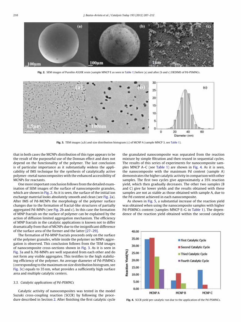
210 J. Bastos-Arrieta et al. / Catalysis Today 193 (2012) 207– 212
Fig. 2. SEM images of Purolite A520E resin (sample MNCP E as seen in Table 1) before (a) and after (b and c) DEDIMS of Pd-PSMNCs.
stogra
ttdicpM
iweAcaoaodo
ogoFni(Fa
3
Sd
Pd-PSMNCs content (samples MNCP E–G in Table 1). The depen-dence of the reaction yield obtained within the second catalytic
Fig. 3. TEM images (a,b) and size distribution hi
hat in both cases the MCNPs distribution of this type appears to behe result of the purposeful use of the Donnan effect and does notepend on the functionality of the polymer. The last conclusion
s of particular importance as it substantially widens the appli-ability of IMS technique for the synthesis of catalytically activeolymer–metal nanocomposites with the enhanced accessibility ofCNPs for reactants.One more important conclusion follows from the detailed exam-
nation of SEM images of the surface of nanocomposite granules,hich are shown in Fig. 2. As it is seen, the surface of the initial ion
xchange material looks absolutely smooth and clean (see Fig. 2a).fter IMS of Pd-MCNPs the morphology of the polymer surfacehanges due to the formation of fractal-like structures of partiallyggregated Pd-MNPs (see Fig. 2b and c). In this case the formationf MNP fractals on the surface of polymer can be explained by thection of diffusion limited aggregation mechanism. The efficiencyf MNP fractals in the catalytic applications is known not to differramatically from that of MCNPs due to the insignificant differencef the surface area of the former and the latter [27–29].
The formation of Pd-MNP fractals proceeds only on the surfacef the polymer granules, while inside the polymer no MNPs aggre-ation is observed. This conclusion follows from the TEM imagesf nanocomposite cross-sections shown in Fig. 3. As it is seen inig. 3a and b, Pd-MNPs are well separated from each other and doot form any visible aggregates. This testifies to the high stabiliz-
ng efficiency of the polymer. An average diameter of Pd-PSMNCscorresponding to the maximum on size distribution histogram, seeig. 3c) equals to 35 nm, what provides a sufficiently high surfacerea and multiple catalytic centers.
.3. Catalytic applications of Pd-PSMNCs
Catalytic activity of nanocomposites was tested in the modeluzuki cross-coupling reaction (SCCR) by following the proce-ure described in Section 2. After finishing the first catalytic cycle
m (c) of MCNP A (sample MNCP 3, see Table 1).
the granulated nanocomposite was separated from the reactionmixture by simple filtration and then reused in sequential cycles.The results of this series of experiments for nanocomposite sam-ples MNCP A–C (see Table 1) are shown in Fig. 4. As it is seen,the nanocomposite with the maximum Pd content (sample A)demonstrates the higher catalytic activity in comparison with othersamples. The first two cycles give approximately a 35% reactionyield, which then gradually decreases. The other two samples (Band C) give far lower yields and the results obtained with thesesamples are not as stable as those obtained with sample A, due tothe Pd content achieved in each nanocomposite.
As shown in Fig. 5, a substantial increase of the reaction yieldwas obtained when using the nanocomposite samples with higher
Fig. 4. SCCR yield per catalytic run due to the application of the Pd-PSMNCs.
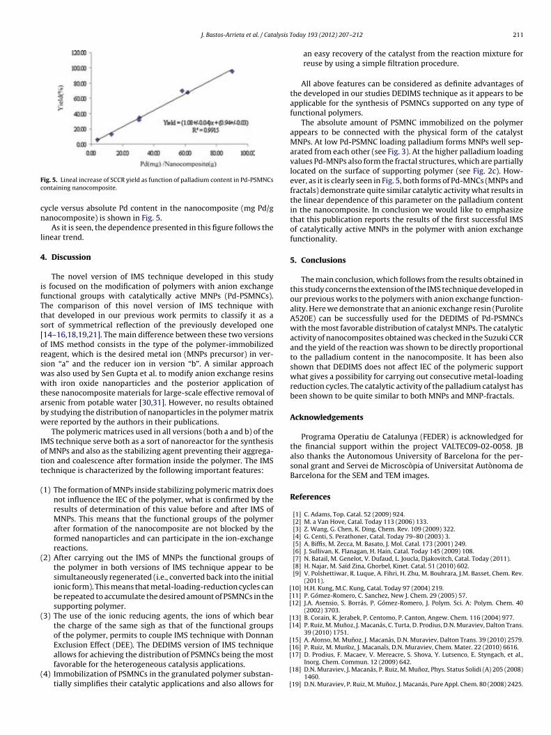
J. Bastos-Arrieta et al. / Catalysis T
Fc
cn
l
4
ifTts[orswwtabw
Iott
(
(
(
(
[[[
[[
[[
ig. 5. Lineal increase of SCCR yield as function of palladium content in Pd-PSMNCsontaining nanocomposite.
ycle versus absolute Pd content in the nanocomposite (mg Pd/ganocomposite) is shown in Fig. 5.
As it is seen, the dependence presented in this figure follows theinear trend.
. Discussion
The novel version of IMS technique developed in this studys focused on the modification of polymers with anion exchangeunctional groups with catalytically active MNPs (Pd-PSMNCs).he comparison of this novel version of IMS technique withhat developed in our previous work permits to classify it as aort of symmetrical reflection of the previously developed one14–16,18,19,21]. The main difference between these two versionsf IMS method consists in the type of the polymer-immobilizedeagent, which is the desired metal ion (MNPs precursor) in ver-ion “a” and the reducer ion in version “b”. A similar approachas also used by Sen Gupta et al. to modify anion exchange resinsith iron oxide nanoparticles and the posterior application of
hese nanocomposite materials for large-scale effective removal ofrsenic from potable water [30,31]. However, no results obtainedy studying the distribution of nanoparticles in the polymer matrixere reported by the authors in their publications.
The polymeric matrices used in all versions (both a and b) of theMS technique serve both as a sort of nanoreactor for the synthesisf MNPs and also as the stabilizing agent preventing their aggrega-ion and coalescence after formation inside the polymer. The IMSechnique is characterized by the following important features:
1) The formation of MNPs inside stabilizing polymeric matrix doesnot influence the IEC of the polymer, what is confirmed by theresults of determination of this value before and after IMS ofMNPs. This means that the functional groups of the polymerafter formation of the nanocomposite are not blocked by theformed nanoparticles and can participate in the ion-exchangereactions.
2) After carrying out the IMS of MNPs the functional groups ofthe polymer in both versions of IMS technique appear to besimultaneously regenerated (i.e., converted back into the initialionic form). This means that metal-loading-reduction cycles canbe repeated to accumulate the desired amount of PSMNCs in thesupporting polymer.
3) The use of the ionic reducing agents, the ions of which bearthe charge of the same sigh as that of the functional groupsof the polymer, permits to couple IMS technique with DonnanExclusion Effect (DEE). The DEDIMS version of IMS technique
allows for achieving the distribution of PSMNCs being the mostfavorable for the heterogeneous catalysis applications.4) Immobilization of PSMNCs in the granulated polymer substan-tially simplifies their catalytic applications and also allows for
[
[
[
oday 193 (2012) 207– 212 211
an easy recovery of the catalyst from the reaction mixture forreuse by using a simple filtration procedure.
All above features can be considered as definite advantages ofthe developed in our studies DEDIMS technique as it appears to beapplicable for the synthesis of PSMNCs supported on any type offunctional polymers.
The absolute amount of PSMNC immobilized on the polymerappears to be connected with the physical form of the catalystMNPs. At low Pd-PSMNC loading palladium forms MNPs well sep-arated from each other (see Fig. 3). At the higher palladium loadingvalues Pd-MNPs also form the fractal structures, which are partiallylocated on the surface of supporting polymer (see Fig. 2c). How-ever, as it is clearly seen in Fig. 5, both forms of Pd-MNCs (MNPs andfractals) demonstrate quite similar catalytic activity what results inthe linear dependence of this parameter on the palladium contentin the nanocomposite. In conclusion we would like to emphasizethat this publication reports the results of the first successful IMSof catalytically active MNPs in the polymer with anion exchangefunctionality.
5. Conclusions
The main conclusion, which follows from the results obtained inthis study concerns the extension of the IMS technique developed inour previous works to the polymers with anion exchange function-ality. Here we demonstrate that an anionic exchange resin (PuroliteA520E) can be successfully used for the DEDIMS of Pd-PSMNCswith the most favorable distribution of catalyst MNPs. The catalyticactivity of nanocomposites obtained was checked in the Suzuki CCRand the yield of the reaction was shown to be directly proportionalto the palladium content in the nanocomposite. It has been alsoshown that DEDIMS does not affect IEC of the polymeric supportwhat gives a possibility for carrying out consecutive metal-loadingreduction cycles. The catalytic activity of the palladium catalyst hasbeen shown to be quite similar to both MNPs and MNP-fractals.
Acknowledgements
Programa Operatiu de Catalunya (FEDER) is acknowledged forthe financial support within the project VALTEC09-02-0058. JBalso thanks the Autonomous University of Barcelona for the per-sonal grant and Servei de Microscòpia of Universitat Autònoma deBarcelona for the SEM and TEM images.
References
[1] C. Adams, Top. Catal. 52 (2009) 924.[2] M. a Van Hove, Catal. Today 113 (2006) 133.[3] Z. Wang, G. Chen, K. Ding, Chem. Rev. 109 (2009) 322.[4] G. Centi, S. Perathoner, Catal. Today 79–80 (2003) 3.[5] A. Biffis, M. Zecca, M. Basato, J. Mol. Catal. 173 (2001) 249.[6] J. Sullivan, K. Flanagan, H. Hain, Catal. Today 145 (2009) 108.[7] N. Batail, M. Genelot, V. Dufaud, L. Joucla, Djakovitch, Catal. Today (2011).[8] H. Najar, M. Saïd Zina, Ghorbel, Kinet. Catal. 51 (2010) 602.[9] V. Polshettiwar, R. Luque, A. Fihri, H. Zhu, M. Bouhrara, J.M. Basset, Chem. Rev.
(2011).10] H.H. Kung, M.C. Kung, Catal. Today 97 (2004) 219.11] P. Gómez-Romero, C. Sanchez, New J. Chem. 29 (2005) 57.12] J.A. Asensio, S. Borrás, P. Gómez-Romero, J. Polym. Sci. A: Polym. Chem. 40
(2002) 3703.13] B. Corain, K. Jerabek, P. Centomo, P. Canton, Angew. Chem. 116 (2004) 977.14] P. Ruiz, M. Munoz, J. Macanás, C. Turta, D. Prodius, D.N. Muraviev, Dalton Trans.
39 (2010) 1751.15] A. Alonso, M. Munoz, J. Macanás, D.N. Muraviev, Dalton Trans. 39 (2010) 2579.16] P. Ruiz, M. Munoz, J. Macanaıs, D.N. Muraviev, Chem. Mater. 22 (2010) 6616.
17] D. Prodius, F. Macaev, V. Mereacre, S. Shova, Y. Lutsenco, E. Styngach, et al.,Inorg. Chem. Commun. 12 (2009) 642.18] D.N. Muraviev, J. Macanás, P. Ruiz, M. Munoz, Phys. Status Solidi (A) 205 (2008)
1460.19] D.N. Muraviev, P. Ruiz, M. Munoz, J. Macanás, Pure Appl. Chem. 80 (2008) 2425.

2 lysis T
[[[[[[
[
[
[
12 J. Bastos-Arrieta et al. / Cata
20] P. Barbaro, F. Liguori, Chem. Rev. 109 (2009) 515.21] D.N. Muraviev, Contrib. Sci. 3 (2005) 19.22] F.G. Donnan, J. Membr. Sci. 100 (1995) 45.
23] J.D.S. Newman, G.J. Blanchard, Langmuir ACS J. Surf. Colloid 22 (2006) 5882.24] C. Yang, J. Xing, Y. Guan, J. Liu, H. Liu, J. Alloy Compds. 385 (2004) 283.25] C. Liu, X. Wu, T. Klemmer, N. Shukla, X. Yang, D. Weller, et al., J. Phys. Chem. B108 (2004) 6121.26] W.G. Rothschild, Catal. Rev. 33 (2007) 71–107.
[
[
[
oday 193 (2012) 207– 212
27] D. Romeu, J. Ramírez, R. Silva, O. Pérez, A. González, M. Yacamán, Phys. Rev.Lett. 57 (1986) 2552.
28] L. Sander, S. Ghaisas, Phys. Chem. A 233 (1996) 629.
29] S. Sarkar, P. Chatterjee, L.H. Cumbal1, A. Sen Gupta, Chem. Eng. J. 166 (2010)1923.30] S. Sarkar, L. Blaney, A. Gupta, D. Ghosh, A. Sen Gupta, React. Funct. Polym. 67
(2007) 1599.31] P. Puttamraju, A. Sen Gupta, Ind. Eng. Chem. Res. 45 (2006) 7737.

ANNEX 2
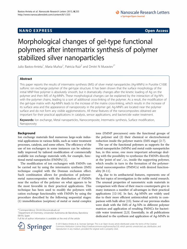
NANO EXPRESS Open Access
Morphological changes of gel-type functionalpolymers after intermatrix synthesis of polymerstabilized silver nanoparticlesJulio Bastos-Arrieta1, Maria Muñoz1, Patricia Ruiz2 and Dmitri N Muraviev1*
Abstract
This paper reports the results of intermatrix synthesis (IMS) of silver metal nanoparticles (Ag-MNPs) in Purolite C100Esulfonic ion exchange polymer of the gel-type structure. It has been shown that the surface morphology of theinitial MNP-free polymer is absolutely smooth, but it dramatically changes after the kinetic loading of Ag on thepolymer and then IMS of Ag-MNPs. These morphological changes can be explained by the interaction of Ag-NPswith the polymer chains, leading to a sort of additional cross-linking of the polymer. As a result, the modification ofthe gel-type matrix with Ag-MNPs leads to the increase of the matrix cross-linking, which results in the increase ofits surface area and the appearance of nanoporosity in the polymer gel. Ag-MNPs are located near the polymersurface and do not form any visible agglomerations. All these features of the nanocomposites obtained areimportant for their practical applications in catalysis, sensor applications, and bactericide water treatment.
Keywords: Ion exchange, Metal nanoparticles, Nanocomposite, Intermatrix synthesis, Surface modification,Nanoporosity
BackgroundIon exchange materials find numerous large-scale indus-trial applications in various fields, such as water treatmentprocesses, catalysis, and some others. The efficiency of theuse of ion exchangers in some instances can be substan-tially improved by tailored modification of commerciallyavailable ion exchange materials with, for example, func-tional metal nanoparticles (FMNPs) [1].The modification of ion exchangers with FMNPs can
be carried out by using the intermatrix synthesis (IMS)technique coupled with the Donnan exclusion effect.Such combination allows for production of polymer-metal nanocomposites with the distribution of FMNPsnear the surface of the polymer on what appears to bethe most favorable in their practical applications. Thistechnique has been used to modify the polymers withcation exchange functionality with FMNPs by using theprocedure described by the following sequential stages:(1) immobilization (sorption) of metal or metal complex
ions (FMNP precursors) onto the functional groups ofthe polymer and (2) their chemical or electrochemicalreduction inside the polymer matrix (IMS stage) [2-7].The use of the functional polymers as supports for the
metal nanoparticles (MNPs) and metal oxide nanoparticleshas, in this sense, one more important advantage deal-ing with the possibility to synthesize the FMNPs directlyat the ‘point of use’ , i.e., inside the supporting polymer,which results in turn in the formation of the polymer-metal nanocomposites (PMNCs) with desired function-ality [8-11].Ag, due to its antibacterial features, represents one of
the hot topics of investigation in the noble metal research.The unusual properties of nanometric scale materials incomparison with those of their macro counterparts give inmany instances a number of advantages in their practicalapplications [12-14]. In fact, Ag-MNPs are widely useddue to their more efficient antimicrobial activity in com-parison with bulk silver [15]. Some of our previous studieswere dealt with the IMS of Ag-NPs in different polymermatrices and application of resulting PMNCs for bacteri-cide water treatment [2,3]. Essentially, in all publicationsdedicated to the synthesis and application of Ag-MNPs in
* Correspondence: [email protected] of Chemistry, Universitat Autònoma de Barcelona, Barcelona08193, SpainFull list of author information is available at the end of the article
© 2013 Bastos-Arrieta et al.; licensee Springer. This is an Open Access article distributed under the terms of the CreativeCommons Attribution License (http://creativecommons.org/licenses/by/2.0), which permits unrestricted use, distribution, andreproduction in any medium, provided the original work is properly cited.
Bastos-Arrieta et al. Nanoscale Research Letters 2013, 8:255http://www.nanoscalereslett.com/content/8/1/255
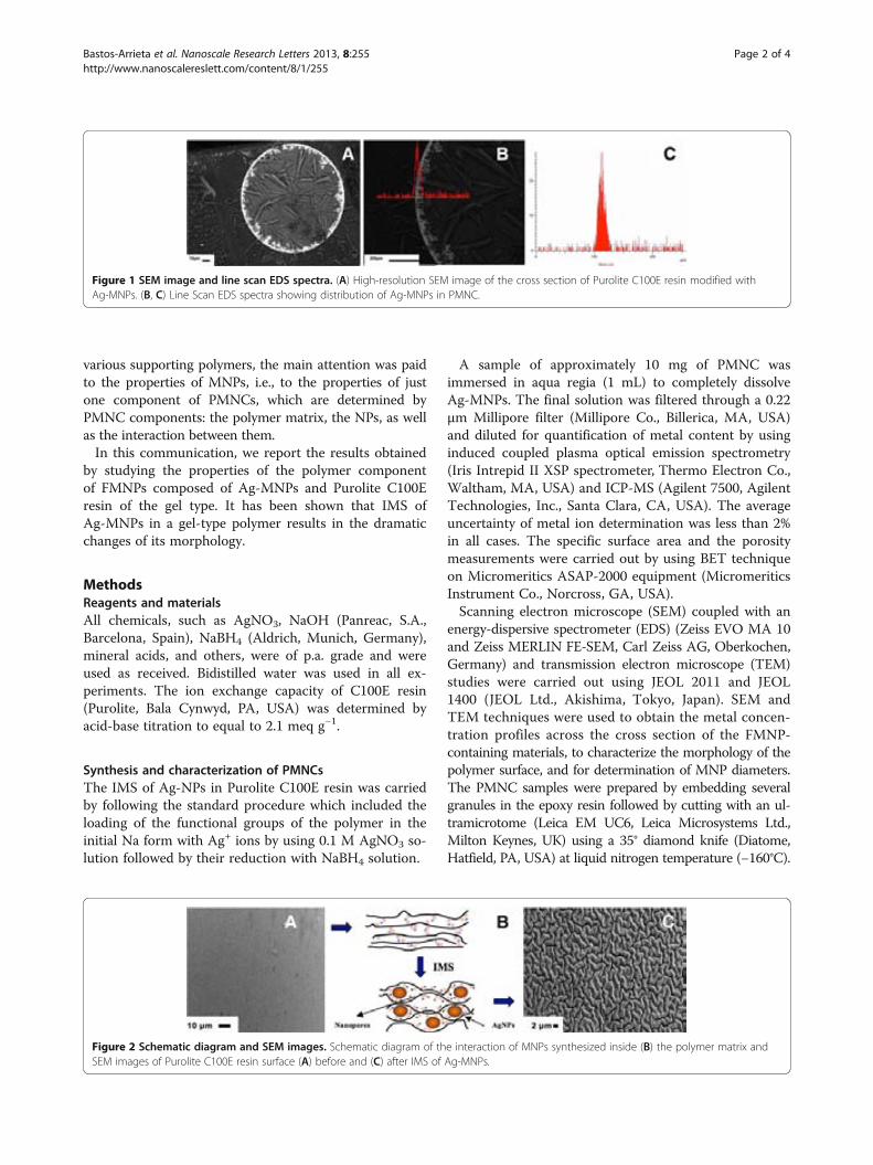
various supporting polymers, the main attention was paidto the properties of MNPs, i.e., to the properties of justone component of PMNCs, which are determined byPMNC components: the polymer matrix, the NPs, as wellas the interaction between them.In this communication, we report the results obtained
by studying the properties of the polymer componentof FMNPs composed of Ag-MNPs and Purolite C100Eresin of the gel type. It has been shown that IMS ofAg-MNPs in a gel-type polymer results in the dramaticchanges of its morphology.
MethodsReagents and materialsAll chemicals, such as AgNO3, NaOH (Panreac, S.A.,Barcelona, Spain), NaBH4 (Aldrich, Munich, Germany),mineral acids, and others, were of p.a. grade and wereused as received. Bidistilled water was used in all ex-periments. The ion exchange capacity of C100E resin(Purolite, Bala Cynwyd, PA, USA) was determined byacid-base titration to equal to 2.1 meq g−1.
Synthesis and characterization of PMNCsThe IMS of Ag-NPs in Purolite C100E resin was carriedby following the standard procedure which included theloading of the functional groups of the polymer in theinitial Na form with Ag+ ions by using 0.1 M AgNO3 so-lution followed by their reduction with NaBH4 solution.
A sample of approximately 10 mg of PMNC wasimmersed in aqua regia (1 mL) to completely dissolveAg-MNPs. The final solution was filtered through a 0.22μm Millipore filter (Millipore Co., Billerica, MA, USA)and diluted for quantification of metal content by usinginduced coupled plasma optical emission spectrometry(Iris Intrepid II XSP spectrometer, Thermo Electron Co.,Waltham, MA, USA) and ICP-MS (Agilent 7500, AgilentTechnologies, Inc., Santa Clara, CA, USA). The averageuncertainty of metal ion determination was less than 2%in all cases. The specific surface area and the porositymeasurements were carried out by using BET techniqueon Micromeritics ASAP-2000 equipment (MicromeriticsInstrument Co., Norcross, GA, USA).Scanning electron microscope (SEM) coupled with an
energy-dispersive spectrometer (EDS) (Zeiss EVO MA 10and Zeiss MERLIN FE-SEM, Carl Zeiss AG, Oberkochen,Germany) and transmission electron microscope (TEM)studies were carried out using JEOL 2011 and JEOL1400 (JEOL Ltd., Akishima, Tokyo, Japan). SEM andTEM techniques were used to obtain the metal concen-tration profiles across the cross section of the FMNP-containing materials, to characterize the morphology of thepolymer surface, and for determination of MNP diameters.The PMNC samples were prepared by embedding severalgranules in the epoxy resin followed by cutting with an ul-tramicrotome (Leica EM UC6, Leica Microsystems Ltd.,Milton Keynes, UK) using a 35° diamond knife (Diatome,Hatfield, PA, USA) at liquid nitrogen temperature (−160°C).
Figure 1 SEM image and line scan EDS spectra. (A) High-resolution SEM image of the cross section of Purolite C100E resin modified withAg-MNPs. (B, C) Line Scan EDS spectra showing distribution of Ag-MNPs in PMNC.
Figure 2 Schematic diagram and SEM images. Schematic diagram of the interaction of MNPs synthesized inside (B) the polymer matrix andSEM images of Purolite C100E resin surface (A) before and (C) after IMS of Ag-MNPs.
Bastos-Arrieta et al. Nanoscale Research Letters 2013, 8:255 Page 2 of 4http://www.nanoscalereslett.com/content/8/1/255
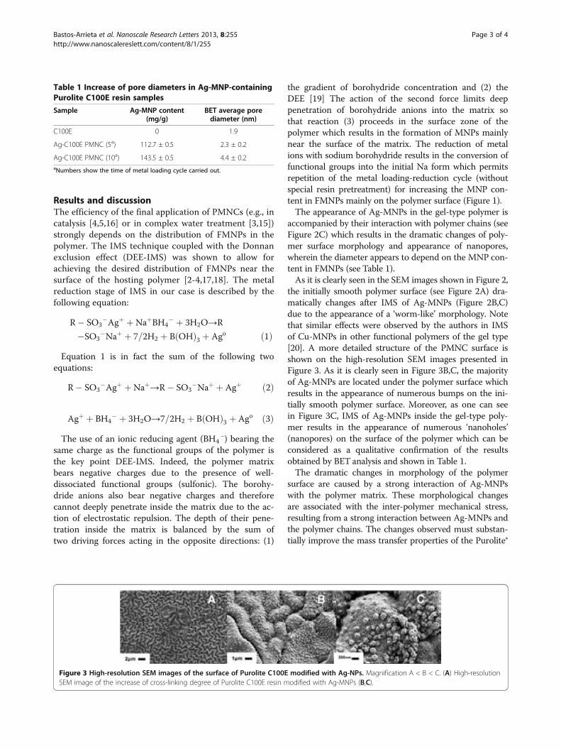
Results and discussionThe efficiency of the final application of PMNCs (e.g., incatalysis [4,5,16] or in complex water treatment [3,15])strongly depends on the distribution of FMNPs in thepolymer. The IMS technique coupled with the Donnanexclusion effect (DEE-IMS) was shown to allow forachieving the desired distribution of FMNPs near thesurface of the hosting polymer [2-4,17,18]. The metalreduction stage of IMS in our case is described by thefollowing equation:
R SO3Agþ þNaþBH4
þ 3H2O→R
SO3Naþ þ 7=2H2 þ B OHð Þ3 þ Ago ð1Þ
Equation 1 is in fact the sum of the following twoequations:
R SO3Agþ þNaþ→R SO3
Naþ þ Agþ ð2Þ
Agþ þ BH4 þ 3H2O→7=2H2 þ B OHð Þ3 þ Ago ð3Þ
The use of an ionic reducing agent (BH4−) bearing the
same charge as the functional groups of the polymer isthe key point DEE-IMS. Indeed, the polymer matrixbears negative charges due to the presence of well-dissociated functional groups (sulfonic). The borohy-dride anions also bear negative charges and thereforecannot deeply penetrate inside the matrix due to the ac-tion of electrostatic repulsion. The depth of their pene-tration inside the matrix is balanced by the sum oftwo driving forces acting in the opposite directions: (1)
the gradient of borohydride concentration and (2) theDEE [19] The action of the second force limits deeppenetration of borohydride anions into the matrix sothat reaction (3) proceeds in the surface zone of thepolymer which results in the formation of MNPs mainlynear the surface of the matrix. The reduction of metalions with sodium borohydride results in the conversion offunctional groups into the initial Na form which permitsrepetition of the metal loading-reduction cycle (withoutspecial resin pretreatment) for increasing the MNP con-tent in FMNPs mainly on the polymer surface (Figure 1).The appearance of Ag-MNPs in the gel-type polymer is
accompanied by their interaction with polymer chains (seeFigure 2C) which results in the dramatic changes of poly-mer surface morphology and appearance of nanopores,wherein the diameter appears to depend on the MNP con-tent in FMNPs (see Table 1).As it is clearly seen in the SEM images shown in Figure 2,
the initially smooth polymer surface (see Figure 2A) dra-matically changes after IMS of Ag-MNPs (Figure 2B,C)due to the appearance of a ‘worm-like’ morphology. Notethat similar effects were observed by the authors in IMSof Cu-MNPs in other functional polymers of the gel type[20]. A more detailed structure of the PMNC surface isshown on the high-resolution SEM images presented inFigure 3. As it is clearly seen in Figure 3B,C, the majorityof Ag-MNPs are located under the polymer surface whichresults in the appearance of numerous bumps on the ini-tially smooth polymer surface. Moreover, as one can seein Figure 3C, IMS of Ag-MNPs inside the gel-type poly-mer results in the appearance of numerous ‘nanoholes’(nanopores) on the surface of the polymer which can beconsidered as a qualitative confirmation of the resultsobtained by BET analysis and shown in Table 1.The dramatic changes in morphology of the polymer
surface are caused by a strong interaction of Ag-MNPswith the polymer matrix. These morphological changesare associated with the inter-polymer mechanical stress,resulting from a strong interaction between Ag-MNPs andthe polymer chains. The changes observed must substan-tially improve the mass transfer properties of the Purolite®
Table 1 Increase of pore diameters in Ag-MNP-containingPurolite C100E resin samples
Sample Ag-MNP content(mg/g)
BET average porediameter (nm)
C100E 0 1.9
Ag-C100E PMNC (5a) 112.7 ± 0.5 2.3 ± 0.2
Ag-C100E PMNC (10a) 143.5 ± 0.5 4.4 ± 0.2aNumbers show the time of metal loading cycle carried out.
Figure 3 High-resolution SEM images of the surface of Purolite C100E modified with Ag-NPs. Magnification A < B < C. (A) High-resolutionSEM image of the increase of cross-linking degree of Purolite C100E resin modified with Ag-MNPs (B,C).
Bastos-Arrieta et al. Nanoscale Research Letters 2013, 8:255 Page 3 of 4http://www.nanoscalereslett.com/content/8/1/255
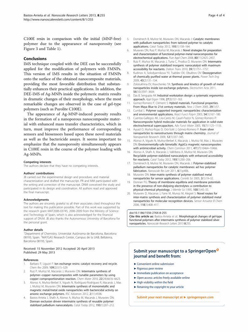
C100E resin in comparison with the initial (MNP-free)polymer due to the appearance of nanoporosity (seeFigure 3 and Table 1).
ConclusionsIMS technique coupled with the DEE can be successfullyapplied for the modification of polymers with FMNPs.This version of IMS results in the situation of FMNPsonto the surface of the obtained nanocomposite materials,providing the most favorable distribution that substan-tially enhances their practical applications. In addition, theDEE-IMS of Ag-MNPs inside the polymeric matrix resultsin dramatic changes of their morphology, where the mostremarkable changes are observed in the case of gel-typepolymers (such as Purolite C100E).The appearance of Ag-MNP-induced porosity results
in the formation of a nanoporous nanocomposite mater-ial with enhanced mass transfer characteristics, which inturn, must improve the performance of correspondingsensors and biosensors based upon these novel materialsas well as the bactericide assays. It seems important toemphasize that the nanoporosity simultaneously appearsin C100E resin in the course of the polymer loading withAg-MNPs.
Competing interestsThe authors declare that they have no competing interests.
Authors' contributionsJB carried out the experimental design and procedure, and materialcharacterization and drafted the manuscript. PR and MM participated withthe writing and correction of the manuscript. DNM conceived the study andparticipated in its design and coordination. All authors read and approvedthe final manuscript.
AcknowledgmentsThe authors are sincerely grateful to all their associates cited throughout thetext for making this publication possible. Part of this work was supported bythe research grant MAT2006-03745, 2006-2009 from the Ministry of Scienceand Technology of Spain, which is also acknowledged for the financialsupport of DN.M. JB also thanks the Autonomous University of Barcelona forthe personal grant.
Author details1Department of Chemistry, Universitat Autònoma de Barcelona, Barcelona08193, Spain. 2MATGAS Research Center, Campus de la UAB, Bellaterra,Barcelona 08193, Spain.
Received: 15 November 2012 Accepted: 20 April 2013Published: 29 May 2013
References1. Barbaro P, Liguori F: Ion exchange resins: catalyst recovery and recycle.
Chem Rev 2009, 109(2):515–529.2. Ruiz P, Muñoz M, Macanás J, Muraviev DN: Intermatrix synthesis of
polymer−copper nanocomposites with tunable parameters by usingcopper comproportionation reaction. Chem Mater 2010, 22(24):6616–6623.
3. Alonso A, Muñoz-Berbel X, Vigués N, Rodríguez-Rodríguez R, Macanás J, MasJ, Muñoz M, Muraviev DN: Intermatrix synthesis of monometallic andmagnetic metal/metal oxide nanoparticles with bactericidal activity onanionic exchange polymers. RSC Advances 2012, 2(11):4596.
4. Bastos-Arrieta J, Shafir A, Alonso A, Muñoz M, Macanás J, Muraviev DN:Donnan exclusion driven intermatrix synthesis of reusable polymerstabilized palladium nanocatalysts. Catal Today 2012, 193(1):207–212.
5. Domènech B, Muñoz M, Muraviev DN, Macanás J: Catalytic membraneswith palladium nanoparticles: from tailored polymer to catalyticapplications. Catal Today 2012, 193(1):158–164.
6. Muraviev DN, Ruiz P, Muñoz M, Macanás J: Novel strategies for preparationand characterization of functional polymer-metal nanocomposites forelectrochemical applications. Pure Appl Chem 2008, 80(11):2425–2437.
7. Ruiz P, Muñoz M, Macanás J, Turta C, Prodius D, Muraviev DN: Intermatrixsynthesis of polymer stabilized inorganic nanocatalyst with maximumaccessibility for reactants. Dalton Trans 2010, 39(7):1751–1757.
8. Kudinov A, Solodyannikova YV, Tsabilev OV, Obukhov DV: Deoxygenationof chemically purified water at thermal power plants. Power Tech Eng2009, 43(2):131–134.
9. Zolotukhina EV, Kravchenko TA: Synthesis and kinetics of growth of metalnanoparticles inside ion-exchange polymers. Electrochim Acta 2011,56(10):3597–3604.
10. Das B, Sengupta AK: Industrial workstation design: a systematic ergonomicsapproach. Appl Ergon 1996, 27(3):157–163.
11. Gomez-Romero P, Clément S: Hybrid materials. Functional properties.From Maya Blue to 21st century materials. New J Chem 2005, 29(1):57.
12. Cumbal L: Polymer supported inorganic nanoparticles: characterizationand environmental applications. React Funct Polym 2003, 54(1):167–180.
13. Cuentas-Gallegos AK, Lira-Cantú M, Casañ-Pastor N, Gómez-Romero P:Nanocomposite hybrid molecular materials for application in solid-stateelectrochemical supercapacitors. Adv Funct Mater 2005, 15(7):1125–1133.
14. Ayyad O, Muñoz-Rojas D, Oró-Solé J, Gómez-Romero P: From silvernanoparticles to nanostructures through matrix chemistry. Journal ofNanoparticle Research 2009, 12(1):337–345.
15. Alonso A, Vigués N, Muñoz-Berbel X, Macanás J, Muñoz M, Mas J, MuravievDN: Environmentally-safe bimetallic Ag@Co magnetic nanocompositeswith antimicrobial activity. Chem Commun 2011, 47(37):10464–10466.
16. Alonso A, Shafir A, Macanás J, Vallribera A, Muñoz M, Muraviev DN:Recyclable polymer-stabilized nanocatalysts with enhanced accessibilityfor reactants. Catal Today 2012, 193(1):200–206.
17. Domènech B, Muñoz M, Muraviev DN, Macanás J: Polymer-stabilizedpalladium nanoparticles for catalytic membranes: ad hoc polymerfabrication. Nanoscale Res Lett 2011, 6(1):p406.
18. Muraviev DN: Inter-matrix synthesis of polymer stabilised metalnanoparticles for sensor applications. Contrib Sci 2005, 3(1):19–32.
19. Donnan FG: Theory of membrane equilibria and membrane potentialsin the presence of non-dialysing electrolytes: a contribution tophysical-chemical physiology. J Membr Sci 1995, 100(1):45–55.
20. Muraviev D, Macanas J, Farre M, Munoz M, Alegret S: Novel routes forinter-matrix synthesis and characterization of polymer stabilized metalnanoparticles for molecular recognition devices. Sensor Actuator B Chem2006, 118(1):408–417.
doi:10.1186/1556-276X-8-255Cite this article as: Bastos-Arrieta et al.: Morphological changes of gel-typefunctional polymers after intermatrix synthesis of polymer stabilized silvernanoparticles. Nanoscale Research Letters 2013 8:255.
Submit your manuscript to a journal and benefi t from:
7 Convenient online submission
7 Rigorous peer review
7 Immediate publication on acceptance
7 Open access: articles freely available online
7 High visibility within the fi eld
7 Retaining the copyright to your article
Submit your next manuscript at 7 springeropen.com
Bastos-Arrieta et al. Nanoscale Research Letters 2013, 8:255 Page 4 of 4http://www.nanoscalereslett.com/content/8/1/255

ANNEX 3

Simple synthesis of CdS Quantum Dots on multiwall carbon
nanotubes: to make CNTs visible.
Journal: ChemComm
Manuscript ID: CC-COM-06-2014-004210
Article Type: Communication
Date Submitted by the Author: 02-Jun-2014
Complete List of Authors: Bastos Arrieta, Julio; Universitat Autònoma de Barcelona, Chemistry Muñoz, Jose Maria; Universitat Autònoma de Barcelona, Baeza, Mireia; Universitat Autònoma de Barcelona, Céspedes, Francisco; Universtitat Autònoma de Barcelona, Dept. of Chemistry Munoz, Maria; Universitat Autònoma de Barcelona, Muraviev, Dmitri N.; Universitat Autnoma de Barcelona, Departament de Qumica
ChemComm

Chemical Communications Guidelines for referees
ChemComm is a forum for urgent high quality communications from across the chemical sciences. Communications in ChemComm should be preliminary accounts of original and significant work in any area of chemistry that is likely to prove of wide general appeal or exceptional specialist interest. The 2012 impact factor for ChemComm is 6.37. Only a fraction of research warrants publication in ChemComm and strict refereeing standards should be applied. Our current rejection rate is around 70%. Acceptance should only be
recommended if the content is of such urgency or impact that rapid publication will be advantageous to the progress of chemical research. Routine and incremental work – however competently researched and reported – should not be recommended for publication. Thank you very much for your assistance in evaluating this manuscript. General Guidance Referees have the responsibility to treat the manuscript as confidential. Please be aware of our Ethical Guidelines, which contain full information on the responsibilities of referees and authors, and our Refereeing Procedure and Policy. Supporting information and characterisation of new compounds Experimental information must be provided to enable other researchers to reproduce the work accurately. It is the responsibility of authors to provide fully convincing evidence for the homogeneity, purity and identity of all compounds they claim as new. This evidence is required to establish that the properties and constants reported are those of the compound with the new structure claimed. Please assess the evidence presented in support of the claims made by the authors and comment on whether adequate supporting information has been provided to address the above. Further details on the requirements for characterisation criteria can be found here. When preparing your report, please: • comment on the originality, significance, impact and scientific reliability of the work; • state clearly whether you would like to see the article accepted or rejected and give detailed
comments (with references, as appropriate) that will both help the Editor to make a decision on the article and the authors to improve it.
Please inform the Editor if: • there is a conflict of interest; • there is a significant part of the work which you are not able to referee with confidence; • the work, or a significant part of the work, has previously been published; • you believe the work, or a significant part of the work, is currently submitted elsewhere; • the work represents part of an unduly fragmented investigation.
Submit your report at http://mc.manuscriptcentral.com/chemcomm
Page 1 of 11 ChemComm
Analytical Unit
Department of Chemistry
University Autonomous of Barcelona (UAB)
08193, Bellaterra, Barcelona, Spain.
February 10th, 2014
Tel: +34 935812119
e-mail : [email protected]
RSC Chemical Communications
Editorial Board
We are sending this original research Communication entitled: “Simple
synthesis of CdS Quantum Dots on multiwall carbon nanotubes: to make CNTs
visible” in order to be considered for publication in your journal.
In the present, work we present for the first time the results obtained from the
application of Intermatrix Synthesis technique as an effective method for the in situ
synthesis of CdS quantum dots (QDs) on the surface of multiwall carbon nanotubes
(MWCNTs), based on the ion exchange nature of this material and tested their
feasibility for electrochemical sensing purposes.
Moreover, taking into account the supposition of the preferential formation of CdS-QDs
on the MWCNTs surface, it was demonstrated that after modification with QDs the
intensity of fluorescent emission appears to be directly proportional to the CNTs
concentration in water. This can be used for the detection of CNTs in water samples.
Thus, a research path is open to develop and optimize a simple analytical procedure
based on the above supposition for the detection of MWCNTs in water, replying to the
current necessity of analytical methodologies for the determination and quantification of
nanomaterials in environmental samples.
We hope that this Communication would fit and be of interest for publication in
RSC Chemical Communications Journal.
With best wishes,
Dmitri N. Muraviev
Page 2 of 11ChemComm

Journal Name
Cite this: DOI: 10.1039/c0xx00000x
www.rsc.org/xxxxxx
Dynamic Article Links
ARTICLE TYPE
This journal is © The Royal Society of Chemistry [year] [journal], [year], [vol], 00–00 | 1
Simple synthesis of CdS Quantum Dots on multiwall carbon nanotubes: to make CNTs visible.
Julio Bastos-Arrietaa, Jose Muñoza, Maria Muñoza, Mireia Baezaa, Francisco Céspedesa and Dmitri N. Muraviev*a
Received (in XXX, XXX) Xth XXXXXXXXX 20XX, Accepted Xth XXXXXXXXX 20XX 5
DOI: 10.1039/b000000x
In this communication we report a simple and effective
method for the in situ synthesis of CdS quantum dots (QDs)
on the surface of multiwall carbon nanotubes (MWCNTs),
based on the ion exchange nature of this material. These QDs 10
have a favourable distribution over the surface of the
nanotubes and their fluorescent properties can be used for
detection of MWCNTs in water.
The progress in many fields of the modern technology within
the last decade is determined by the rapid development and wide 15
application of various nanomaterials (NMs) and nanocomposites
on their base.1–4 At the same time, insufficient safety of these
materials may result in the uncontrollable release of NMs into the
environment.5–9 Consequently it results in the serious concerns
dealing with10,11: 20
1) the approved higher toxicity of many NM in comparison with
their bulk counterparts,
2) the absence of the legislation normative for permitted levels of
various NMs in water and air
3) the absence of the adequate analytical techniques for detection 25
of NMs in the environment.
The last point seems to be the most important one as the solution
of this problem would provide the base for the quantitative
analytical detection of various NMs and elaboration of the
corresponding legislation normative for their permitted levels in 30
the environment. In this regard it is essential to develop the
analytical methodology to quantify NMs concentration, for
example in water samples. This procedure can be based on the
specific properties of the analyte under determination, such as for
example Carbon Nanotubes (CNTs), which are known to be the 35
most toxic carbon nanoform in comparison with, e.g. fullerenes
and nanodimonds.12,13,14 . In this regard the development of
analytical techniques permitting their detection in the
environment seems particularly important.
CNTs find various applications since their discovery due to their 40
structural properties (almost one-dimensional), stability and high
electrical and thermal conductivities. All these features make
CNTs a valuable component of different kind of composites,
which are used as a base for design of various devices such as,
for example electrochemical sensors.15, 16, 17 CNTs are known to 45
be partially oxidized and as the result, bear on their surface the
carboxylic functional groups. From this viewpoint they can be
considered as a “nanoanalog” of fibrous carboxylic ion exchange
materials such as, for example FIBAN K-4.18,19 The surface of
these materials can be easily modified with metal nanoparticles 50
(MNPs) as it has been shown in our recent publications.20,21
This modification is carried out by using the intermatrix
synthesis (IMS) technique22,23 representing a simple and effective
procedure, which includes two stages based on aquatic
chemistry: 1) loading the functional groups with MNPs precursor 55
(e.g., metal or metal complex ions), and 2) in situ formation of
MNPs in the polymer matrix after reduction of MNPs precursor.
Similar methodology can be used for modification of CNTs
surface with easily detectable species, such as, for example,
quantum dots (QDs). 60
QDs are known to present quantum confinement effects during
light excitation, which gives them interesting optical and semi-
conducting properties. Tuning these features and coupled them
with its surface modification or using them for the surface
modification of CNTs, led to explore the application of these 65
nanocrystals to the field of sensors (fluorescent and biosensors)
and to bioassays.24–27
Previous works related to decoration or modification of CNTs
with nanocrystals such as Metal NanoParticles (MNPs), usually
involve thermal evaporation28, electroless deposition by galvanic 70
replacement29, MNPs hydrosol absorption30, electrochemical
deposition31. These methods are mainly based on the use of high
temperatures or organic solvents, involving a significant
environmental impact of the process. There are greener
methodologies for the decoration of CNTs with MNPs such as 75
seed-mediated growth32,33 in which metal salts solutions can be
reduced by a strong reducing agent(e.g. NaBH4) at room
temperature and aqueous solution. However to the knowledge of
the authors no information regarding modification of CNTs with
QDs can be found in the literature. 80
Modification of reactive surfaces such as CNTs or multi-wall
CNTs (MWCNTs) with QDs can be carried out by taking
advantage of their ion exchange functionality and using a slightly
modified IMS procedure (see above). In this case the first stage
remains absolutely the same (loading the functional groups with 85
NPs precursor), while the second one includes the formation of
NPs (QDs) by precipitation reaction (instead of reduction).
Moreover, the synthesis of QDs on the surface of MWCNTs
provides the final nanocomposite material with additional
enhanced properties in terms of its electrocatalytic features (as 90
shown in supplementary information SI.1.1).
Page 3 of 11 ChemComm
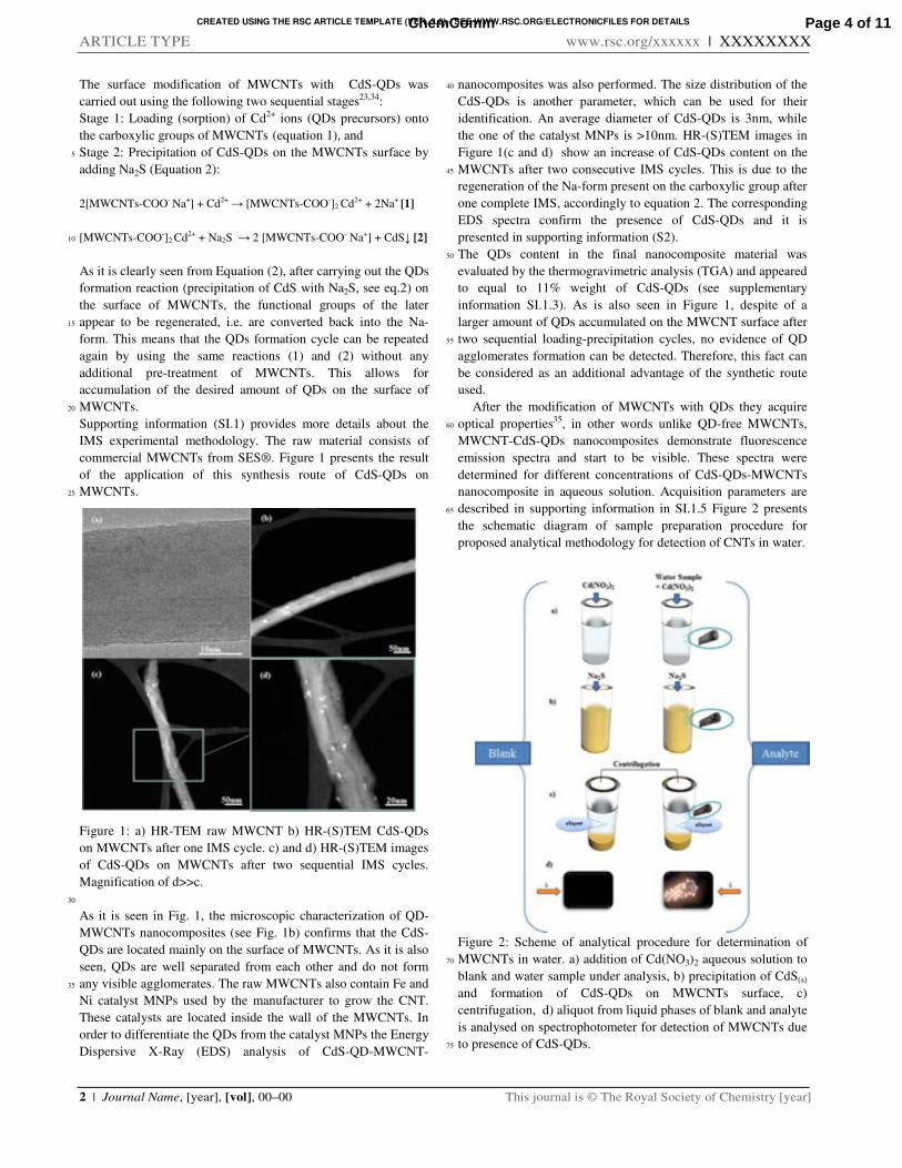
CREATED USING THE RSC ARTICLE TEMPLATE (VER. 3.0) - SEE WWW.RSC.ORG/ELECTRONICFILES FOR DETAILS
ARTICLE TYPE www.rsc.org/xxxxxx | XXXXXXXX
2 | Journal Name, [year], [vol], 00–00 This journal is © The Royal Society of Chemistry [year]
The surface modification of MWCNTs with CdS-QDs was
carried out using the following two sequential stages23,34:
Stage 1: Loading (sorption) of Cd2+ ions (QDs precursors) onto
the carboxylic groups of MWCNTs (equation 1), and
Stage 2: Precipitation of CdS-QDs on the MWCNTs surface by 5
adding Na2S (Equation 2):
2[MWCNTs-COO- Na+] + Cd2+ → [MWCNTs-COO-]2 Cd2+ + 2Na+ [1]
[MWCNTs-COO-]2 Cd2+ + Na2S → 2 [MWCNTs-COO- Na+] + CdS↓ [2] 10
As it is clearly seen from Equation (2), after carrying out the QDs
formation reaction (precipitation of CdS with Na2S, see eq.2) on
the surface of MWCNTs, the functional groups of the later
appear to be regenerated, i.e. are converted back into the Na-15
form. This means that the QDs formation cycle can be repeated
again by using the same reactions (1) and (2) without any
additional pre-treatment of MWCNTs. This allows for
accumulation of the desired amount of QDs on the surface of
MWCNTs. 20
Supporting information (SI.1) provides more details about the
IMS experimental methodology. The raw material consists of
commercial MWCNTs from SES®. Figure 1 presents the result
of the application of this synthesis route of CdS-QDs on
MWCNTs. 25
Figure 1: a) HR-TEM raw MWCNT b) HR-(S)TEM CdS-QDs
on MWCNTs after one IMS cycle. c) and d) HR-(S)TEM images
of CdS-QDs on MWCNTs after two sequential IMS cycles.
Magnification of d>>c.
30
As it is seen in Fig. 1, the microscopic characterization of QD-
MWCNTs nanocomposites (see Fig. 1b) confirms that the CdS-
QDs are located mainly on the surface of MWCNTs. As it is also
seen, QDs are well separated from each other and do not form
any visible agglomerates. The raw MWCNTs also contain Fe and 35
Ni catalyst MNPs used by the manufacturer to grow the CNT.
These catalysts are located inside the wall of the MWCNTs. In
order to differentiate the QDs from the catalyst MNPs the Energy
Dispersive X-Ray (EDS) analysis of CdS-QD-MWCNT-
nanocomposites was also performed. The size distribution of the 40
CdS-QDs is another parameter, which can be used for their
identification. An average diameter of CdS-QDs is 3nm, while
the one of the catalyst MNPs is >10nm. HR-(S)TEM images in
Figure 1(c and d) show an increase of CdS-QDs content on the
MWCNTs after two consecutive IMS cycles. This is due to the 45
regeneration of the Na-form present on the carboxylic group after
one complete IMS, accordingly to equation 2. The corresponding
EDS spectra confirm the presence of CdS-QDs and it is
presented in supporting information (S2).
The QDs content in the final nanocomposite material was 50
evaluated by the thermogravimetric analysis (TGA) and appeared
to equal to 11% weight of CdS-QDs (see supplementary
information SI.1.3). As is also seen in Figure 1, despite of a
larger amount of QDs accumulated on the MWCNT surface after
two sequential loading-precipitation cycles, no evidence of QD 55
agglomerates formation can be detected. Therefore, this fact can
be considered as an additional advantage of the synthetic route
used.
After the modification of MWCNTs with QDs they acquire
optical properties35, in other words unlike QD-free MWCNTs, 60
MWCNT-CdS-QDs nanocomposites demonstrate fluorescence
emission spectra and start to be visible. These spectra were
determined for different concentrations of CdS-QDs-MWCNTs
nanocomposite in aqueous solution. Acquisition parameters are
described in supporting information in SI.1.5 Figure 2 presents 65
the schematic diagram of sample preparation procedure for
proposed analytical methodology for detection of CNTs in water.
Figure 2: Scheme of analytical procedure for determination of
MWCNTs in water. a) addition of Cd(NO3)2 aqueous solution to 70
blank and water sample under analysis, b) precipitation of CdS(s)
and formation of CdS-QDs on MWCNTs surface, c)
centrifugation, d) aliquot from liquid phases of blank and analyte
is analysed on spectrophotometer for detection of MWCNTs due
to presence of CdS-QDs. 75
Page 4 of 11ChemComm
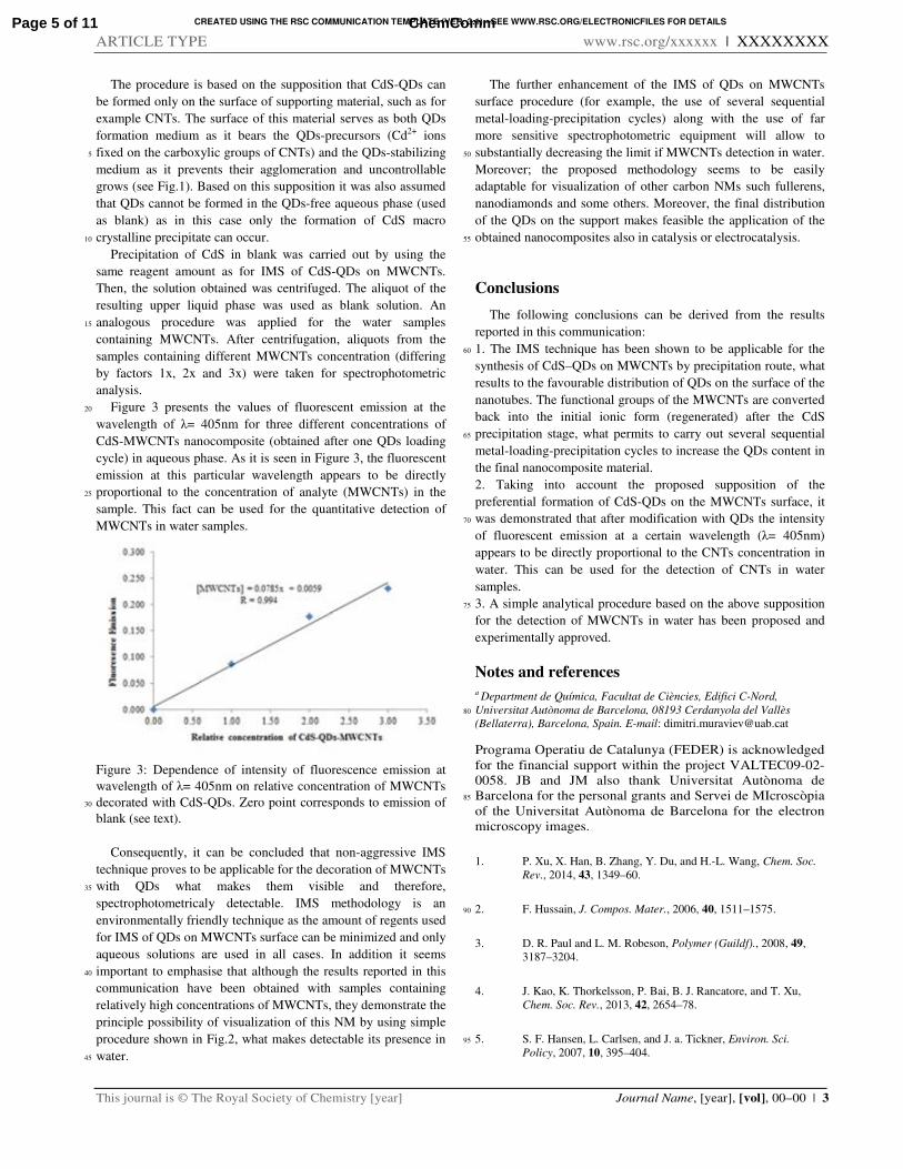
CREATED USING THE RSC COMMUNICATION TEMPLATE (VER. 3.1) - SEE WWW.RSC.ORG/ELECTRONICFILES FOR DETAILS
ARTICLE TYPE www.rsc.org/xxxxxx | XXXXXXXX
This journal is © The Royal Society of Chemistry [year] Journal Name, [year], [vol], 00–00 | 3
The procedure is based on the supposition that CdS-QDs can
be formed only on the surface of supporting material, such as for
example CNTs. The surface of this material serves as both QDs
formation medium as it bears the QDs-precursors (Cd2+ ions
fixed on the carboxylic groups of CNTs) and the QDs-stabilizing 5
medium as it prevents their agglomeration and uncontrollable
grows (see Fig.1). Based on this supposition it was also assumed
that QDs cannot be formed in the QDs-free aqueous phase (used
as blank) as in this case only the formation of CdS macro
crystalline precipitate can occur. 10
Precipitation of CdS in blank was carried out by using the
same reagent amount as for IMS of CdS-QDs on MWCNTs.
Then, the solution obtained was centrifuged. The aliquot of the
resulting upper liquid phase was used as blank solution. An
analogous procedure was applied for the water samples 15
containing MWCNTs. After centrifugation, aliquots from the
samples containing different MWCNTs concentration (differing
by factors 1x, 2x and 3x) were taken for spectrophotometric
analysis.
Figure 3 presents the values of fluorescent emission at the 20
wavelength of λ= 405nm for three different concentrations of
CdS-MWCNTs nanocomposite (obtained after one QDs loading
cycle) in aqueous phase. As it is seen in Figure 3, the fluorescent
emission at this particular wavelength appears to be directly
proportional to the concentration of analyte (MWCNTs) in the 25
sample. This fact can be used for the quantitative detection of
MWCNTs in water samples.
Figure 3: Dependence of intensity of fluorescence emission at
wavelength of λ= 405nm on relative concentration of MWCNTs
decorated with CdS-QDs. Zero point corresponds to emission of 30
blank (see text).
Consequently, it can be concluded that non-aggressive IMS
technique proves to be applicable for the decoration of MWCNTs
with QDs what makes them visible and therefore, 35
spectrophotometricaly detectable. IMS methodology is an
environmentally friendly technique as the amount of regents used
for IMS of QDs on MWCNTs surface can be minimized and only
aqueous solutions are used in all cases. In addition it seems
important to emphasise that although the results reported in this 40
communication have been obtained with samples containing
relatively high concentrations of MWCNTs, they demonstrate the
principle possibility of visualization of this NM by using simple
procedure shown in Fig.2, what makes detectable its presence in
water. 45
The further enhancement of the IMS of QDs on MWCNTs
surface procedure (for example, the use of several sequential
metal-loading-precipitation cycles) along with the use of far
more sensitive spectrophotometric equipment will allow to
substantially decreasing the limit if MWCNTs detection in water. 50
Moreover; the proposed methodology seems to be easily
adaptable for visualization of other carbon NMs such fullerens,
nanodiamonds and some others. Moreover, the final distribution
of the QDs on the support makes feasible the application of the
obtained nanocomposites also in catalysis or electrocatalysis. 55
Conclusions
The following conclusions can be derived from the results
reported in this communication:
1. The IMS technique has been shown to be applicable for the 60
synthesis of CdS–QDs on MWCNTs by precipitation route, what
results to the favourable distribution of QDs on the surface of the
nanotubes. The functional groups of the MWCNTs are converted
back into the initial ionic form (regenerated) after the CdS
precipitation stage, what permits to carry out several sequential 65
metal-loading-precipitation cycles to increase the QDs content in
the final nanocomposite material.
2. Taking into account the proposed supposition of the
preferential formation of CdS-QDs on the MWCNTs surface, it
was demonstrated that after modification with QDs the intensity 70
of fluorescent emission at a certain wavelength (λ= 405nm)
appears to be directly proportional to the CNTs concentration in
water. This can be used for the detection of CNTs in water
samples.
3. A simple analytical procedure based on the above supposition 75
for the detection of MWCNTs in water has been proposed and
experimentally approved.
Notes and references a Department de Química, Facultat de Ciències, Edifici C-Nord,
Universitat Autònoma de Barcelona, 08193 Cerdanyola del Vallès 80
(Bellaterra), Barcelona, Spain. E-mail: [email protected]
Programa Operatiu de Catalunya (FEDER) is acknowledged
for the financial support within the project VALTEC09-02-
0058. JB and JM also thank Universitat Autònoma de
Barcelona for the personal grants and Servei de MIcroscòpia 85
of the Universitat Autònoma de Barcelona for the electron
microscopy images.
1. P. Xu, X. Han, B. Zhang, Y. Du, and H.-L. Wang, Chem. Soc.
Rev., 2014, 43, 1349–60.
2. F. Hussain, J. Compos. Mater., 2006, 40, 1511–1575. 90
3. D. R. Paul and L. M. Robeson, Polymer (Guildf)., 2008, 49,
3187–3204.
4. J. Kao, K. Thorkelsson, P. Bai, B. J. Rancatore, and T. Xu,
Chem. Soc. Rev., 2013, 42, 2654–78.
5. S. F. Hansen, L. Carlsen, and J. a. Tickner, Environ. Sci. 95
Policy, 2007, 10, 395–404.
Page 5 of 11 ChemComm
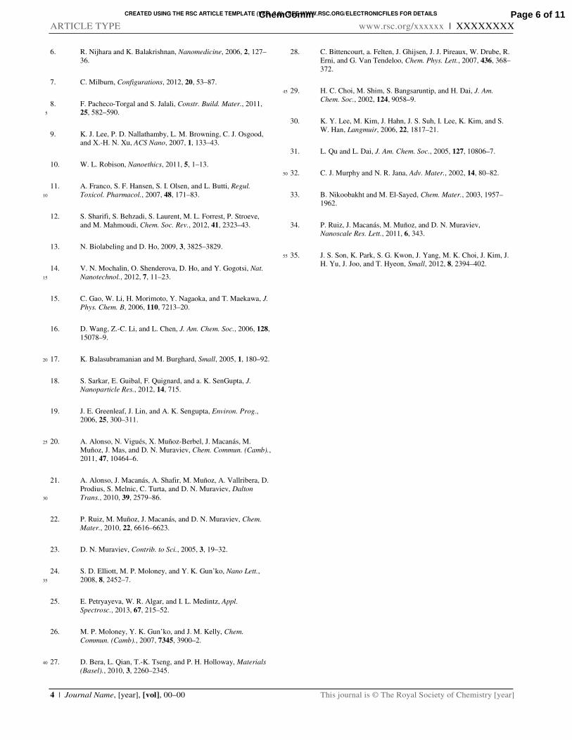
CREATED USING THE RSC ARTICLE TEMPLATE (VER. 3.0) - SEE WWW.RSC.ORG/ELECTRONICFILES FOR DETAILS
ARTICLE TYPE www.rsc.org/xxxxxx | XXXXXXXX
4 | Journal Name, [year], [vol], 00–00 This journal is © The Royal Society of Chemistry [year]
6. R. Nijhara and K. Balakrishnan, Nanomedicine, 2006, 2, 127–
36.
7. C. Milburn, Configurations, 2012, 20, 53–87.
8. F. Pacheco-Torgal and S. Jalali, Constr. Build. Mater., 2011,
25, 582–590. 5
9. K. J. Lee, P. D. Nallathamby, L. M. Browning, C. J. Osgood,
and X.-H. N. Xu, ACS Nano, 2007, 1, 133–43.
10. W. L. Robison, Nanoethics, 2011, 5, 1–13.
11. A. Franco, S. F. Hansen, S. I. Olsen, and L. Butti, Regul.
Toxicol. Pharmacol., 2007, 48, 171–83. 10
12. S. Sharifi, S. Behzadi, S. Laurent, M. L. Forrest, P. Stroeve,
and M. Mahmoudi, Chem. Soc. Rev., 2012, 41, 2323–43.
13. N. Biolabeling and D. Ho, 2009, 3, 3825–3829.
14. V. N. Mochalin, O. Shenderova, D. Ho, and Y. Gogotsi, Nat.
Nanotechnol., 2012, 7, 11–23. 15
15. C. Gao, W. Li, H. Morimoto, Y. Nagaoka, and T. Maekawa, J.
Phys. Chem. B, 2006, 110, 7213–20.
16. D. Wang, Z.-C. Li, and L. Chen, J. Am. Chem. Soc., 2006, 128,
15078–9.
17. K. Balasubramanian and M. Burghard, Small, 2005, 1, 180–92. 20
18. S. Sarkar, E. Guibal, F. Quignard, and a. K. SenGupta, J.
Nanoparticle Res., 2012, 14, 715.
19. J. E. Greenleaf, J. Lin, and A. K. Sengupta, Environ. Prog.,
2006, 25, 300–311.
20. A. Alonso, N. Vigués, X. Muñoz-Berbel, J. Macanás, M. 25
Muñoz, J. Mas, and D. N. Muraviev, Chem. Commun. (Camb).,
2011, 47, 10464–6.
21. A. Alonso, J. Macanás, A. Shafir, M. Muñoz, A. Vallribera, D.
Prodius, S. Melnic, C. Turta, and D. N. Muraviev, Dalton
Trans., 2010, 39, 2579–86. 30
22. P. Ruiz, M. Muñoz, J. Macanás, and D. N. Muraviev, Chem.
Mater., 2010, 22, 6616–6623.
23. D. N. Muraviev, Contrib. to Sci., 2005, 3, 19–32.
24. S. D. Elliott, M. P. Moloney, and Y. K. Gun’ko, Nano Lett.,
2008, 8, 2452–7. 35
25. E. Petryayeva, W. R. Algar, and I. L. Medintz, Appl.
Spectrosc., 2013, 67, 215–52.
26. M. P. Moloney, Y. K. Gun’ko, and J. M. Kelly, Chem.
Commun. (Camb)., 2007, 7345, 3900–2.
27. D. Bera, L. Qian, T.-K. Tseng, and P. H. Holloway, Materials 40
(Basel)., 2010, 3, 2260–2345.
28. C. Bittencourt, a. Felten, J. Ghijsen, J. J. Pireaux, W. Drube, R.
Erni, and G. Van Tendeloo, Chem. Phys. Lett., 2007, 436, 368–
372.
29. H. C. Choi, M. Shim, S. Bangsaruntip, and H. Dai, J. Am. 45
Chem. Soc., 2002, 124, 9058–9.
30. K. Y. Lee, M. Kim, J. Hahn, J. S. Suh, I. Lee, K. Kim, and S.
W. Han, Langmuir, 2006, 22, 1817–21.
31. L. Qu and L. Dai, J. Am. Chem. Soc., 2005, 127, 10806–7.
32. C. J. Murphy and N. R. Jana, Adv. Mater., 2002, 14, 80–82. 50
33. B. Nikoobakht and M. El-Sayed, Chem. Mater., 2003, 1957–
1962.
34. P. Ruiz, J. Macanás, M. Muñoz, and D. N. Muraviev,
Nanoscale Res. Lett., 2011, 6, 343.
35. J. S. Son, K. Park, S. G. Kwon, J. Yang, M. K. Choi, J. Kim, J. 55
H. Yu, J. Joo, and T. Hyeon, Small, 2012, 8, 2394–402.
Page 6 of 11ChemComm
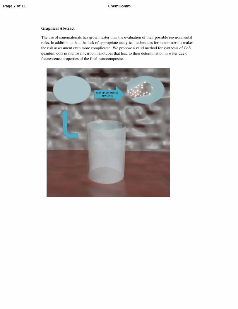
Graphical Abstract
The use of nanomaterials has grown faster than the evaluation of their possible environmental
risks. In addition to that, the lack of appropriate analytical techniques for nanomaterials makes
the risk assessment even more complicated. We propose a valid method for synthesis of CdS
quantum dots in multiwall carbon nanotubes that lead to their determination in water due o
fluorescence properties of the final nanocomposite.
Page 7 of 11 ChemComm
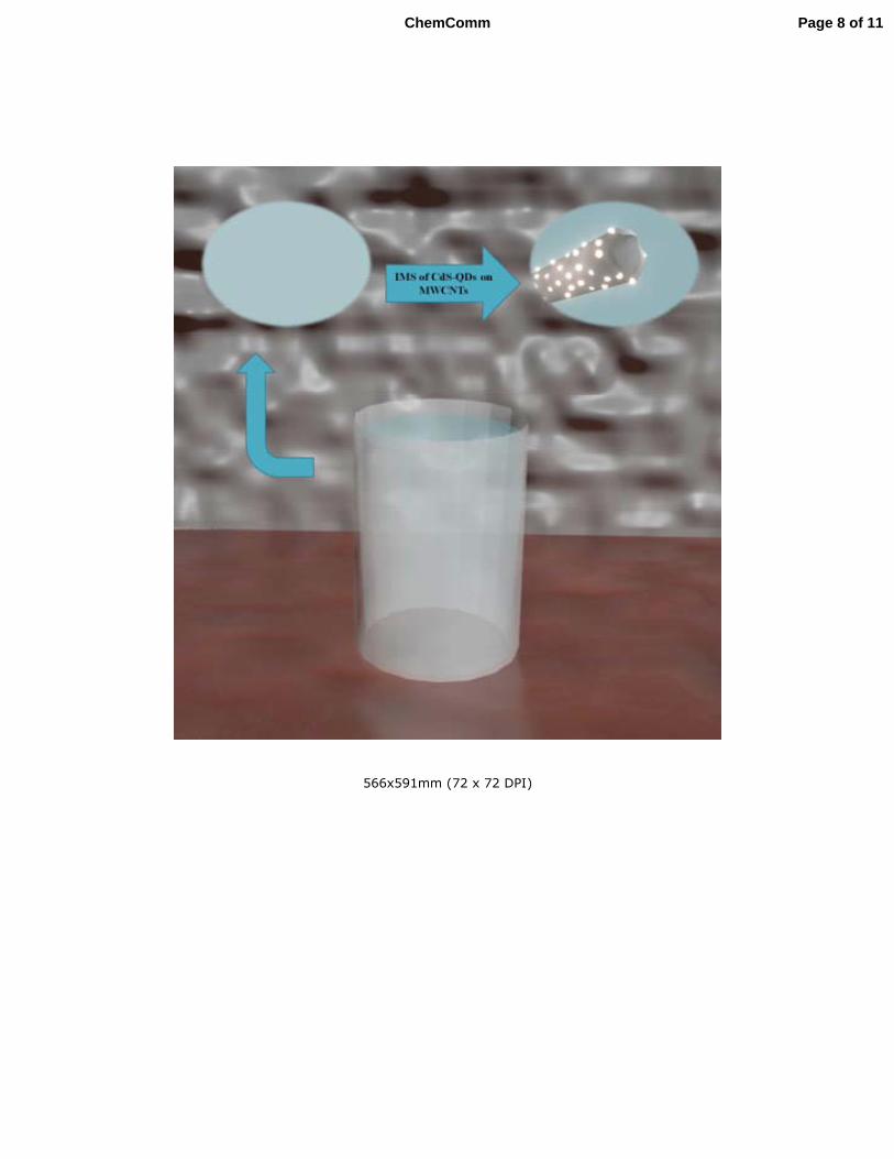
566x591mm (72 x 72 DPI)
Page 8 of 11ChemComm
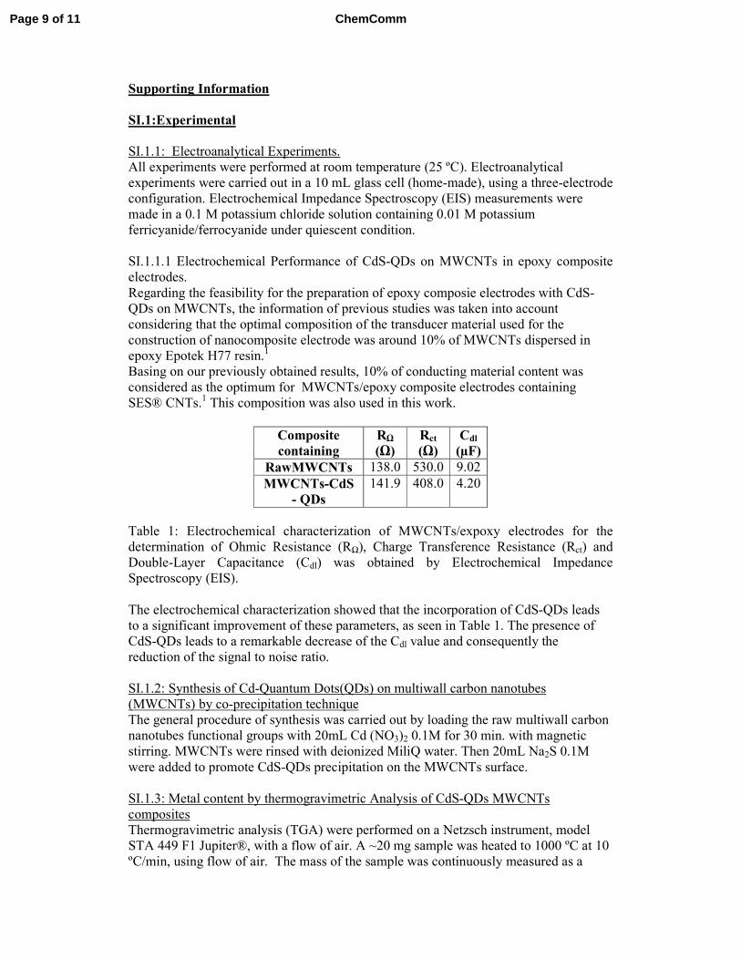
Supporting Information
SI.1:Experimental
SI.1.1: Electroanalytical Experiments.
All experiments were performed at room temperature (25 ºC). Electroanalytical
experiments were carried out in a 10 mL glass cell (home-made), using a three-electrode
configuration. Electrochemical Impedance Spectroscopy (EIS) measurements were
made in a 0.1 M potassium chloride solution containing 0.01 M potassium
ferricyanide/ferrocyanide under quiescent condition.
SI.1.1.1 Electrochemical Performance of CdS-QDs on MWCNTs in epoxy composite
electrodes. Regarding the feasibility for the preparation of epoxy composie electrodes with CdS-
QDs on MWCNTs, the information of previous studies was taken into account
considering that the optimal composition of the transducer material used for the
construction of nanocomposite electrode was around 10% of MWCNTs dispersed in
epoxy Epotek H77 resin.1
Basing on our previously obtained results, 10% of conducting material content was
considered as the optimum for MWCNTs/epoxy composite electrodes containing
SES® CNTs.1 This composition was also used in this work.
Composite containing
RΩ
(Ω) Rct (Ω)
Cdl (µF)
RawMWCNTs 138.0 530.0 9.02
MWCNTs-CdS - QDs
141.9 408.0 4.20
Table 1: Electrochemical characterization of MWCNTs/expoxy electrodes for the
determination of Ohmic Resistance (RΩ), Charge Transference Resistance (Rct) and
Double-Layer Capacitance (Cdl) was obtained by Electrochemical Impedance
Spectroscopy (EIS).
The electrochemical characterization showed that the incorporation of CdS-QDs leads
to a significant improvement of these parameters, as seen in Table 1. The presence of
CdS-QDs leads to a remarkable decrease of the Cdl value and consequently the
reduction of the signal to noise ratio.
SI.1.2: Synthesis of Cd-Quantum Dots(QDs) on multiwall carbon nanotubes
(MWCNTs) by co-precipitation technique
The general procedure of synthesis was carried out by loading the raw multiwall carbon
nanotubes functional groups with 20mL Cd (NO3)2 0.1M for 30 min. with magnetic
stirring. MWCNTs were rinsed with deionized MiliQ water. Then 20mL Na2S 0.1M
were added to promote CdS-QDs precipitation on the MWCNTs surface.
SI.1.3: Metal content by thermogravimetric Analysis of CdS-QDs MWCNTs
composites
Thermogravimetric analysis (TGA) were performed on a Netzsch instrument, model
STA 449 F1 Jupiter®, with a flow of air. A ~20 mg sample was heated to 1000 ºC at 10
ºC/min, using flow of air. The mass of the sample was continuously measured as a
Page 9 of 11 ChemComm
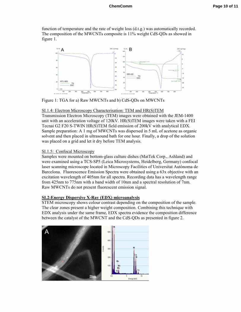
function of temperature and the rate of weight loss (d.t.g.) was automatically recorded.
The composition of the MWCNTs composite is 11% weight CdS-QDs as showed in
figure 1.
Figure 1: TGA for a) Raw MWCNTs and b) CdS-QDs on MWCNTs
SI.1.4: Electron Microscopy Characterisation: TEM and HR(S)TEM
Transmission Electron Microscopy (TEM) images were obtained with the JEM-1400
unit with an acceleration voltage of 120kV. HR(S)TEM images were taken with a FEI
Tecnai G2 F20 S-TWIN HR(S)TEM field emission of 200kV with analytical EDX.
Sample preparation: A 1 mg of MWCNTs was dispersed in 5 mL of acetone as organic
solvent and then placed in ultrasound bath for one hour. Finally, a drop of the solution
was placed on a grid and let it dry before TEM analysis.
SI.1.5: Confocal Microscopy
Samples were mounted on bottom-glass culture dishes (MatTek Corp., Ashland) and
were examined using a TCS-SP5 (Leica Microsystems, Heidelberg, Germany) confocal
laser scanning microscope located in Microscopy Facilities of Universitat Autònoma de
Barcelona. Fluorescence Emission Spectra were obtained using a 63x objective with an
excitation wavelength of 405nm for all spectra. Recording data has a wavelength range
from 425nm to 775nm with a band width of 10nm and a spectral resolution of 7nm.
Raw MWCNTs do not present fluorescent emission signal.
SI.2:Energy Dispersive X-Ray (EDX) microanalysis STEM microscopy shows colour contrast depending on the composition of the sample.
The clear zones present a higher weight composition. Combining this technique with
EDX analysis under the same frame, EDX spectra evidence the composition difference
between the catalyst of the MWCNT and the CdS-QDs as presented in figure 2.
Page 10 of 11ChemComm
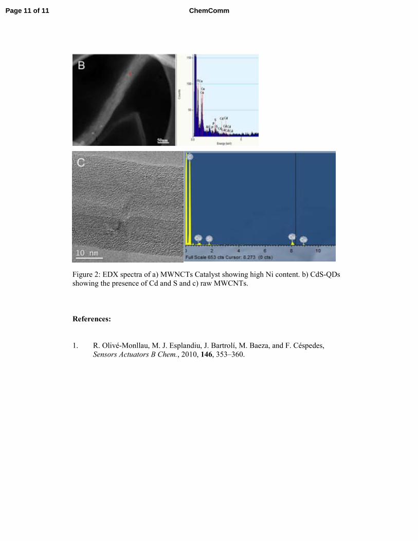
Figure 2: EDX spectra of a) MWNCTs Catalyst showing high Ni content. b) CdS-QDs
showing the presence of Cd and S and c) raw MWCNTs.
References:
1. R. Olivé-Monllau, M. J. Esplandiu, J. Bartrolí, M. Baeza, and F. Céspedes,
Sensors Actuators B Chem., 2010, 146, 353–360.
Page 11 of 11 ChemComm

ANNEX 4

Elsevier Editorial System(tm) for Reactive and Functional Polymers Manuscript Draft Manuscript Number: REACT-D-14-00317 Title: Surface modification of gel-type ion exchange polymers with silver nanoparticles by intermatrix synthesis technique Article Type: Research Paper Corresponding Author: Dr. Dmitri Muraviev, Corresponding Author's Institution: First Author: Dmitri Muraviev Order of Authors: Dmitri Muraviev; Maria Muñoz; Julio BASTOS ARRIETA Suggested Reviewers: Arup SenGupta [email protected] Samuel Sánchez [email protected] Yurii Gun’ko [email protected] Jean-François Lahitte [email protected] Opposed Reviewers:

Dr. Y. Tezuka Editor-in-Chief Reactive and Functional Polymers Tokyo Institute of Technology, Meguro-Ku, Japan
Barcelona, June 12th, 2014
Dear Prof. Tezuka, Attached you will find a file with our paper: “Surface modification of gel-type ion exchange polymers with
silver nanoparticles by intermatrix synthesis technique”, which we would like you to consider for publication
in the Reactive and Functional Polymers journal.
In the present work we report the results obtained in the study of the modification of gel-type polymeric ion
exchange matrices with silver nanoparticles. In previous studies, it was demonstrated the bactericide features of
these nanocomposite materials. In this article we present a deeper analysis of the data obtained from the
characterization of the morphology of the final added value material, demonstrating no significant changes of the
initial ion exchange properties of the supporting matrix after Intermatrix Synthesis of silver nanoparticles with a
favorable distribution, leading to the appearance of nanoporosity and wrinkle structures on the surface of the
polymeric support. In addition it is also demonstrated that the presence of this nanoparticles layer does not
essentially affect the mass transfer process of ions in the matrix as the obtained diffusion coefficient value for
silver ion for the studied system is very close to the value reported by other researchers in similar systems. In the
supplementary information we present a time lapse video of the surface morphology changes of a gel-type resin
due to its modification with Ag functional metal nanoparticles by InterMatrix Synthesis We state that none of the submission has been or will be done to another journal without proper acknowledgment
and permission.
We suggest the following experts as potential referees of our paper:
1. Dr. Jean-François Lahitte, Laboratoire de Génie Chimique, Génie des Interfaces et Milieux Divisés, Route de Narbonne, 118, 31062, Toulouse, France. Fax: 33 0 561556139, E-mail: [email protected] 2. Prof. Yurii Gun’ko, SNIAM Building, School of Chemistry, Trinity College Dublin, College Green, Dublin 2, Ireland. E-mail: [email protected] 3. Dr. Samuel Sanchez Ordóñez, Max Planck Institute for Intelligent Systems Heisenbergstr. 3; 70569 Stuttgart, Germany. E-mail: [email protected] 4. Prof. Arup K. SenGupta Department of Civil & Environmental Engineering, 13 E. Packer Av. Lehigh University Bethlehem, PA 18015 U.S.A. E-mail: [email protected] We keep looking forward to hearing from you on the acceptability of our paper for publication in your journal. Sincerely, Dr. Dmitri N. Muraveiv Dept. of Analytical Chemistry Autonomous University of Barcelona Campus UAB, Bellaterra E-08193 Barcelona, Spain Fax: 34-93-5812379; E-mail: [email protected]
Cover Letter
1
Surface modification of gel-type ion exchange polymers with silver nanoparticles by
intermatrix synthesis technique
J. Bastos-Arrieta, M. Muñoz and D. N. Muraviev.*
Department of Chemistry, Universitat Autònoma de Barcelona, 08193 Bellaterra, Barcelona,
*Corresponding autor: [email protected]
ABSTRACT: This communication reports the results obtained by the modification of gel-type
ion exchange materials with functional metal nanoparticles having biocide activity. The
modification is carried out by using Intermatrix Synthesis technique coupled with Donnan
Exclusion Effect what results in the most favourable distribution of silver nanoparticles near the
surface of nanocomposite material. The surface of polymer-metal nanocomposite is characterised
by the worm-like structure due to the interaction of metal nanoparticles with polymer chains.
This interaction leads to the appearance of nanoporosity in the matrix what enhances its mass-
transfer characteristics. Moreover, it has been shown that modification of gel-type ion
exchangers with silver nanoparticles essentially does not change the ion exchange properties of
the initial polymeric matrix.
Keywords: Ion Exchange, Intermatrix Synthesis, Nanoparticles, Nanocomposite, Surface
Modification.
1. Introduction
Ion exchange materials[18] find numerous large-scale industrial applications in various fields,
such as water treatment[9,23], catalysis[3], and many others. In some instances the efficient use
of ion exchangers can be substantially improved by tailored modification with functional metal
ManuscriptClick here to view linked References
2
nanoparticles (FMNPs) by using the Intermatrix Synthesis (IMS) technique[20]. The first
communication about IMS of FMNPs in ion exchange polymeric materials dates back to 1949, in
which Mills and Dickinson described the preparation of a weakly basic anion exchange resin
containing Copper Metal Nanoparticles (Cu-MNPs or “colloidal copper”) and the use of this
polymer-metal nanocomposite to remove oxygen from water based on its interaction with Cu-
MNPs.[26] Since then, many studies of the modification of ion exchange resins with MNPs
(mainly Cu-MNPs) resulted in the development of a new class of bi-functional ion exchange
materials combining both the ion exchange properties determined by the presence of functional
groups in the matrix, and the redox properties due to the presence of “colloidal metal” or MNPs
in the matrix. They are also known as redoxites and electron exchangers.[27] Redoxites have
found wide application in the complex water treatment processes at power stations for the
removal of hardness ions by ion exchange and dissolved oxygen by redox reactions with MNPs.
However, essentially no information about the sizes and the structures of MNPs in redoxite
matrices and the features of their distribution inside polymers can be found in the literature.
The preparation of such materials was based on the use of the IMS technique and involved in
the case of weakly basic anion exchange polymers the following two consecutive stages:
(a) metal loading:
4R-NH2 + Cu2SO4 → [(R-NH2)4Cu]SO4 [1]
(b) metal reduction:
[(R-NH2)4Cu]SO4 + Na2S2O4 + 2H2O → 2(R-NH3+)2(SO3
2-) + Na2SO4 + Cuo [2]
As clearly follows from equation (2), the functional groups of the polymer bearing Cu-MNPs
precursors (Cu2+ ions) are not protonated to provide the most favourable conditions for formation
of amino-complexes with copper ions. This means that they are not bearing any charges and
dithionite anions can diffuse deeply into the polymer without any restriction. Therefore, one can
quite logically suggest that this provides the conditions for the homogeneous distribution of the
Cu-MNPs throughout the polymer matrix.
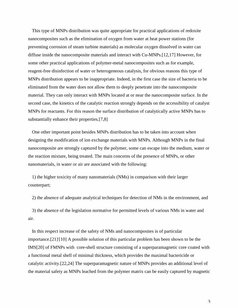
3
This type of MNPs distribution was quite appropriate for practical applications of redoxite
nanocomposites such as the elimination of oxygen from water at heat power stations (for
preventing corrosion of steam turbine materials) as molecular oxygen dissolved in water can
diffuse inside the nanocomposite materials and interact with Cu-MNPs.[12,17] However, for
some other practical applications of polymer-metal nanocomposites such as for example,
reagent-free disinfection of water or heterogeneous catalysis, for obvious reasons this type of
MNPs distribution appears to be inappropriate. Indeed, in the first case the size of bacteria to be
eliminated from the water does not allow them to deeply penetrate into the nanocomposite
material. They can only interact with MNPs located at or near the nanocomposite surface. In the
second case, the kinetics of the catalytic reaction strongly depends on the accessibility of catalyst
MNPs for reactants. For this reason the surface distribution of catalytically active MNPs has to
substantially enhance their properties.[7,8]
One other important point besides MNPs distribution has to be taken into account when
designing the modification of ion exchange materials with MNPs. Although MNPs in the final
nanocomposite are strongly captured by the polymer, some can escape into the medium, water or
the reaction mixture, being treated. The main concerns of the presence of MNPs, or other
nanomaterials, in water or air are associated with the following:
1) the higher toxicity of many nanomaterials (NMs) in comparison with their larger
counterpart;
2) the absence of adequate analytical techniques for detection of NMs in the environment, and
3) the absence of the legislation normative for permitted levels of various NMs in water and
air.
In this respect increase of the safety of NMs and nanocomposites is of particular
importance.[21],[10] A possible solution of this particular problem has been shown to be the
IMS[20] of FMNPs with core-shell structure consisting of a superparamagnetic core coated with
a functional metal shell of minimal thickness, which provides the maximal bactericide or
catalytic activity.[22,24] The superparamagnetic nature of MNPs provides an additional level of
the material safety as MNPs leached from the polymer matrix can be easily captured by magnetic
4
traps to completely prevent any post-contamination of the treated water. In the case of catalytic
applications of polymer-metal nanocomposites this feature of MNPs allows for their easy
recovery for reuse or recycling, particularly important in case of noble MNPs. The presence of
MNPs does not block the functional groups of the polymer so that the polymer-metal nano-
composite can be also used for the removal of some undesired ions (e.g. hardness ions, iron,
nitrates, etc.) from water, which is particularly important in the case of complex water treatment.
Consequently, IMS technique coupled with the Donnan Exlusion Effect (DEE) provides an
environmentally friendly route for the modification of reactive polymer surfaces with functional
metal nanoparticles (FMNPs).[20] Previous reports on the application of IMS for the preparation
of polymer-metal nanocomposites proof the most favourable distribution of the FMNPs near the
surface of the host polymeric matrix with no evident agglomerates. IMS main stages include: 1)
the immobilization (sorption) of metal or metal complex ions (FMNP precursors) onto the
functional groups of the polymer, and 2) their chemical or electrochemical reduction on the
polymer matrix.
In this communication we report the results obtained on the further development of IMS
technique coupled with DEE (DEEIMS ) to produce nanocomposites with desired FMNPs
content and also on the study of morphological changes of nanocomposite structure in
comparison with the initial (FMNPs-free) polymer.
2. Experimental
2.1 Reagents and materials: Metal salts as AgNO3, NaBH4 (Aldrich, Germany), acids and
bases were of p.a. grade were used as received. Bidistilled water was used in all experiments.
The ion exchange capacity for the anionic exchanger gel–typo polymer (quaternary ammine)
and for the cationic exchanger gel–type (sulfonic) were calculated by volumetric titration were
2.1 meq×g-1 in both cases.
For both anionic and cationic breakthrough experiments a column with internal diameter of
0.025m was used for an average bed particle diameter of 500µm. For the breakthrough curve
profile for cationic gel –type polymer modified and unmodified with Ag-FMNPs a fixed bed of
the resin was placed in the column. A Ca2+ solution was introduced with a pump and made go
5
through the fixed bed particles with a flux rate of 1mL/min. Then, each 2mL of effluent were
collected separated samples for the determination of displacement of Na+ to Ca2+ as described in
equation (3).
2[R-SO3−Na+]+ Ca2+ → [R-SO3
−]2Ca2+ + 2Na+ [3]
Similar procedure was followed for anionic breakthrough curve profile. Modified and
unmodified with Ag-FMNPs quaternary amine anionic gel-type exchanger were used as fixed
bed in the column. Cl- solution was introduced with pump and made go through the fixed bed
particles with a flux rate of 1mL/min. Then, each 2mL of effluent were collected separated
samples for the determination of displacement of OH- to Cl- as described in equation (4).
R-(R4-N)+OH- + Na+Cl- → R-(R4-N)+Cl- + Na+OH- [4]
2.2 Intermatrix Syntesis of FMNPs.
2.2.1. IMS of Ag-FMNPs on sulfonic gel–type cation exchanger: The general IMS of Ag-NPs
was carried out by loading of the functional groups of 400mg the sulfonic gel-type polymer with
Ag+ by using 0.1 mol×L-1 aqueous AgNO3 solution (20mL) followed by reduction with 0.1
mol×L-1 aqueous NaBH4. Some kinetic studies were developed by changing metal loading time
at stage 1 of IMS.
2.2.2. IMS of Ag-FMNPs on quaternary ammine gel – type anionic exchanger: IMS of Ag-
FMNPs was carried out by the loading the functional groups of the polymer with anions of the
reducing agent using 0.1 mol×L-1 aqueous NaBH4 solution (20 mL) followed by the treatment of
the resin with 0.1 mol×L-1 AgNO3 solution (20mL). The last stage resulted in the formation of
the Ag-FMNPs on the polymer matrix.
2.3. Analysis of nanocomposite metal composition: A sample of about 10mg of FMNPs-
containing material was immersed in aqua regia (1 mL) to completely dissolve the palladium by
oxidation. The solution was filtered through a 0.22 µm Millipore filter and diluted for metal
content quantification by Induced Coupled Plasma Optical Emission Spectrometry, ICP–OES
(Iris Intrepid II XSP spectrometer Thermo Electron Co) and ICP-MS (Agilent 7500). The
average uncertainty of metal ions determination was less than 2% in all cases.
6
2.4. Scanning Electron Microscopy (SEM) Characterization: Scanning Electron Microscopes
(SEM) coupled with an Energy-Dispersive Spectrometer (EDS) Zeiss EVO MA 10 and Zeiss
MERLIN FE-SEM (Servei de Microscòpia of Universitat Autònoma de Barcelona). SEM
technique was used to obtain the metal distribution profiles across the cross-section of the
FMNPs containing materials, morphology of the polymer surface. The nanocomposite samples
were prepared by embedding several granules in the epoxy resin followed by cutting and cross-
sectioning with a ultramicrotome (Leica EM UC6) using a 35° diamond knife (Diatome) at
liquid nitrogen temperature (-160°C).
3. Results and discussion
Depending on the final application of interest for these nanocomposites, catalytic or
bactericide activity, and with the goal to obtain the most favourable distribution of NPs in the
polymer, IMS methodology has been coupled with the DEE (DEEIMS). The distribution of
FMNPs near the surface of the nanocomposite material may be considered as really the most
favourable for practical application of nanocomposites of this type as it provides an enhanced
access of the substrates (in catalytic applications) or bacteria (in water disinfection) to the
FMNPs layer of the nanocomposite.
Figure 1 shows distribution of Ag–NPs in the nanocomposite where a desirable metal content
is observed mainly on the polymeric surface; this due to DEEIMS methodology as indicated in
the following equations:
Metal loading stage:
R-SO3−Na+ + Ag+ → R-SO3
−Ag+ + Na+ [5]
Metal reduction stage
R-SO3−Ag+ + NaBH4 + 3H2O → R-SO3
−Na+ + 7/2H2 + B(OH)3 + Ag0 [6]
As it is seen from equation (6), the negatively charged borohydride anions (the actual reducing
agent) cannot deeply penetrate into the polymeric matrix bearing the charge of the same sign due
to the action of DEE. As the result, the reduction of Ag ions leading to the formation of Ag-
7
FMNPs proceeds near the surface of the polymer. As it also follows from the same equation, the
functional groups of the polymer appear to be regenerated in the course of metal reduction, i.e.
are converted back into the initial Na-form (see equation (5)). This means that the metal loading
reduction cycle can be repeated without any additional pre-treatment of the polymer what has
been shown to lead to the increase of FMNPs layer thicness in the nanocomposite and
consequently an increase in the FMNPs content.[2,20] The thickness of Ag-FMNPs layer (I.E.,
FMNPs content) can be also tuned by changing the time of the metal loading stage.
The system FMNPs-Polymer shows a series of interactions that leads to the increase of the
stability of the NPs and reduces the possibility of release, reducing as well the environmental
impact of these nanocomposites. This can be explained by the increase of viscosity of the
immobilizing media (polymeric support), and the decrease of the energy of particle-particle
interaction in FMNPs systems regarding the MNPs prepared in solution.[11]
The IMS of MNPs in non-cross-linked polymers was shown to be accompanied by a strong
change of the polymer morphology and the appearance of typical warm-like structure on the
surface of the corresponding polymer-metal nanocomposite.[19] Although the rigidity of cross-
linked polymer matrix is far higher than that of their non-cross-linked analogues, one can also
expect the appearance of similar morphological changes in the case of IMS of MNPs in the
matrices of cross-linked polymers. The confirmation of this supposition is shown in Fig. 2. As it
is seen in Figs. 2a and 2b, after carrying out the metal-loading-reduction cycle (IMS of MNPS)
the initially smooth polymer surface changes its morphology due to the appearance of the worm-
like structure similar to that observed in the case of non-cross-linked polymers product of IMS of
Cu-FMNPs.[19] As it is also seen in Figs. 2e and 2f, the morphological changes result also in the
appearance of nanopores in the gel-type polymer. The appearance of nanoporosity results in turn
in increase of the internal surface area what can be one of the factors explaining the excellent
performance of these nanocomposites in bactericide assays.[1,2]
The bactericide activity of Ag-FMNPs-cation-exchange polymer nanocomposites with
different thickness of Ag-FMNPs layer was tested previously and after 60 minutes contact time
the E. Coli activity decreased to zero. Moreover, it has been also shown that the bactericide
activity of these nancomposites does not depend on the thickness of the Ag-FMNPs layer.
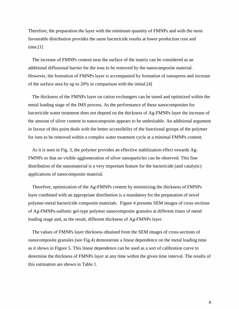
8
Therefore, the preparation the layer with the minimum quantity of FMNPs and with the most
favourable distribution provides the same bactericide results at lower production cost and
time.[1]
The increase of FMNPs content near the surface of the matrix can be considered as an
additional diffusional barrier for the ions to be removed by the nanocomposite material.
However, the formation of FMNPs layer is accompanied by formation of nanopores and increase
of the surface area by up to 20% in comparison with the initial.[4]
The thickness of the FMNPs layer on cation exchangers can be tuned and optimized within the
metal loading stage of the IMS process. As the performance of these nanocomposites for
bactericide water treatment does not depend on the thickness of Ag-FMNPs layer the increase of
the amount of silver content in nanocomposite appears to be undesirable. An additional argument
in favour of this point deals with the better accessibility of the functional groups of the polymer
for ions to be removed within a complex water treatment cycle at a minimal FMNPs content.
As it is seen in Fig. 3, the polymer provides an effective stabilization effect towards Ag-
FMNPs so that no visible agglomeration of silver nanoparticles can be observed. This fine
distribution of the nanomaterial is a very important feature for the bactericide (and catalytic)
applications of nanocomposite material.
Therefore, optimization of the Ag-FMNPs content by minimizing the thickness of FMNPs
layer combined with an appropriate distribution is a mandatory for the preparation of novel
polymer-metal bactericide composite materials. Figure 4 presents SEM images of cross sections
of Ag-FMNPs-sulfonic gel-type polymer nanocomposite granules at different times of metal
loading stage and, as the result, different thickness of Ag-FMNPs layer.
The values of FMNPs layer thickness obtained from the SEM images of cross-sections of
nanocomposite granules (see Fig.4) demonstrate a linear dependence on the metal loading time
as it shows in Figure 5. This linear dependence can be used as a sort of calibration curve to
determine the thickness of FMNPs layer at any time within the given time interval. The results of
this estimation are shown in Table 1.
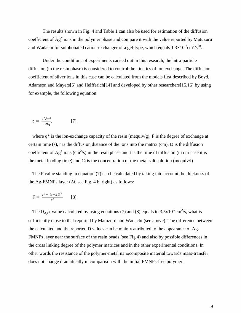
9
The results shown in Fig. 4 and Table 1 can also be used for estimation of the diffusion
coefficient of Ag+ ions in the polymer phase and compare it with the value reported by Matuzuru
and Wadachi for sulphonated cation-exchanger of a gel-type, which equals 1,3×10⁻⁷cm2/s20.
Under the conditions of experiments carried out in this research, the intra-particle
diffusion (in the resin phase) is considered to control the kinetics of ion exchange. The diffusion
coefficient of silver ions in this case can be calculated from the models first described by Boyd,
Adamson and Mayers[6] and Helfferich[14] and developed by other researchers[15,16] by using
for example, the following equation:
∗
, [7]
where q* is the ion-exchange capacity of the resin (mequiv/g), F is the degree of exchange at
certain time (s), r is the diffusion distance of the ions into the matrix (cm), D is the diffusion
coefficient of Ag+ ions (cm2/s) in the resin phase and t is the time of diffusion (in our case it is
the metal loading time) and Ci is the concentration of the metal salt solution (mequiv/l).
The F value standing in equation (7) can be calculated by taking into account the thickness of
the Ag-FMNPs layer (∆l, see Fig. 4 b, right) as follows:
F
[8]
The D value calculated by using equations (7) and (8) equals to 3.5x10⁻⁷cm2/s, what is
sufficiently close to that reported by Matuzuru and Wadachi (see above). The difference between
the calculated and the reported D values can be mainly attributed to the appearance of Ag-
FMNPs layer near the surface of the resin beads (see Fig.4) and also by possible differences in
the cross linking degree of the polymer matrices and in the other experimental conditions. In
other words the resistance of the polymer-metal nanocomposite material towards mass-transfer
does not change dramatically in comparison with the initial FMNPs-free polymer.

10
This conclusion also follows from the results shown in Fig. 6, where the breakthrough curves
obtained within a series of experiments on displacement Na+ with Ca2+ ions from the initial
polymer (FMNPs-free) and nanocomposite samples containing different amounts of FMNPs are
presented. The slope of the curves shown in Fig. 6 qualitatively reflects the kinetic properties of
the corresponding material so that the closer it to 90o the faster is the mass transfer process inside
the polymer matrix. This means that after DEDIMS of FMNPs the functional groups of the ion
exchanger remain almost equally accessible for ions to be removed from the water under
treatment. At the same time what it also follows from the results shown in Fig.6, the slowing
down of the ions diffusion can be decreased by minimizing the thickness of FMNPs layer
moreover the negative impact of this layer is partially compensated by the appearance of
nanoporosity in nanocomposite material (see above).
The area marked by the horizontal and vertical dotted lines in Fig. 6 corresponds to the ion
exchange capacity, q* (see eq.5) of the initial polymer and nanocomposite samples. The vertical
dotted line has to pass through the inflection point of each breakthrough curve and as it is seen
these points for all curves essentially coincide with each other. This means that q* values of all
nanocomposite samples coincide with that of the initial polymer. The q* value estimated from
Fig. 6 appears to equal to 2.0 meq×g-1 what is very close the value of 2.1 meq×g-1 obtained by
the quantitative titration of a certain mass of the initial polymer in the H+-form with alkali
solution.
Figure 7 presents the breakthrough curve profiles obtained with modified and unmodified Ag-
FMNPs anion-exchange resin of gel type. The modification was carried out by DEEIMS of Ag -
FMNPs by using the following reactions:
R-(R4-N)+Cl- + NaBH4 → R-(R4-N)+BH4- + NaCl [9]
R-(R4-N)+BH4 + AgNO3 + 3H2O → R-(R4-N)+NO3-Ag0 + 7/2 H2 + B(OH)3 [10]
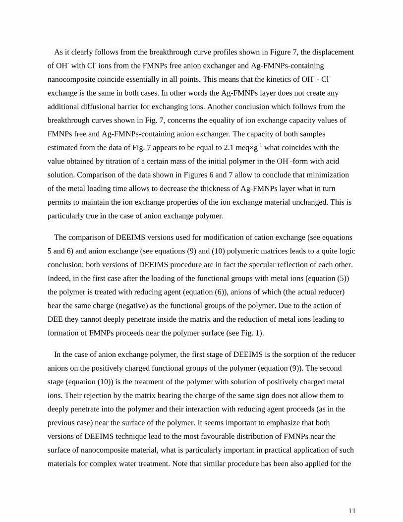
11
As it clearly follows from the breakthrough curve profiles shown in Figure 7, the displacement
of OH- with Cl- ions from the FMNPs free anion exchanger and Ag-FMNPs-containing
nanocomposite coincide essentially in all points. This means that the kinetics of OH- - Cl-
exchange is the same in both cases. In other words the Ag-FMNPs layer does not create any
additional diffusional barrier for exchanging ions. Another conclusion which follows from the
breakthrough curves shown in Fig. 7, concerns the equality of ion exchange capacity values of
FMNPs free and Ag-FMNPs-containing anion exchanger. The capacity of both samples
estimated from the data of Fig. 7 appears to be equal to 2.1 meq×g-1 what coincides with the
value obtained by titration of a certain mass of the initial polymer in the OH--form with acid
solution. Comparison of the data shown in Figures 6 and 7 allow to conclude that minimization
of the metal loading time allows to decrease the thickness of Ag-FMNPs layer what in turn
permits to maintain the ion exchange properties of the ion exchange material unchanged. This is
particularly true in the case of anion exchange polymer.
The comparison of DEEIMS versions used for modification of cation exchange (see equations
5 and 6) and anion exchange (see equations (9) and (10) polymeric matrices leads to a quite logic
conclusion: both versions of DEEIMS procedure are in fact the specular reflection of each other.
Indeed, in the first case after the loading of the functional groups with metal ions (equation (5))
the polymer is treated with reducing agent (equation (6)), anions of which (the actual reducer)
bear the same charge (negative) as the functional groups of the polymer. Due to the action of
DEE they cannot deeply penetrate inside the matrix and the reduction of metal ions leading to
formation of FMNPs proceeds near the polymer surface (see Fig. 1).
In the case of anion exchange polymer, the first stage of DEEIMS is the sorption of the reducer
anions on the positively charged functional groups of the polymer (equation (9)). The second
stage (equation (10)) is the treatment of the polymer with solution of positively charged metal
ions. Their rejection by the matrix bearing the charge of the same sign does not allow them to
deeply penetrate into the polymer and their interaction with reducing agent proceeds (as in the
previous case) near the surface of the polymer. It seems important to emphasize that both
versions of DEEIMS technique lead to the most favourable distribution of FMNPs near the
surface of nanocomposite material, what is particularly important in practical application of such
materials for complex water treatment. Note that similar procedure has been also applied for the
12
synthesis of metal oxide nanoparticles inside ion exchange resins for removal of arsenic from
water[13] and for the preparation of heterogeneous catalysts.[5]
Conclusions
The following conclusions can be derived from the results obtained in this study:
1. The surface modification of ion exchange materials with FMNPs by DEEIMS technique has
been shown to provide the most favourable distribution of FMNPs in the final nanocomposite
materials enhancing their feasible applications such as complex water treatment and
heterogeneous catalysis.
2. DEEIMS has been demonstrated to be a universal synthetic methodology applicable for the
preparation of bifunctional polymer-metal nanocomposites from polymers of either functionality,
i.e. bearing either negatively (e.g., cation exchangers) or positively (e.g., anion exchangers)
charged functional groups.
3. The ion exchange capacity of the polymer is not essentially changed after its modification
with FMNPs as it follows from the breakthrough curve profiles obtained on the unmodified
polymers and modified with FMNPs nanocomposites. As it also follows from these data, the
resistance of the matrix towards ions diffusion can be minimized by varying the thickness of
FMNPs layer and can reach the same value as that of the unmodified polymer.
4. The modification of polymers with negatively charged functional groups with FMNPs by
using DEEIMS technique has been shown to be accompanied by regeneration of the functional
groups, i.e. their conversion into the initial Na+-form. This permit to easily increase the thickness
of FMNPs layer (if required) by carrying out consecutive metal-loading-reduction cycles.
5. Modification of the cation-exchange polymer of gel-type with Ag-FMNPs has been shown to
lead to strong modification of the polymer morphology due to the appearance of the woam-like
structure on the polymer surface and the nanoporosity, which enhances the rate of mass transfer
in the nanocomposite
ASSOCIATED CONTENT
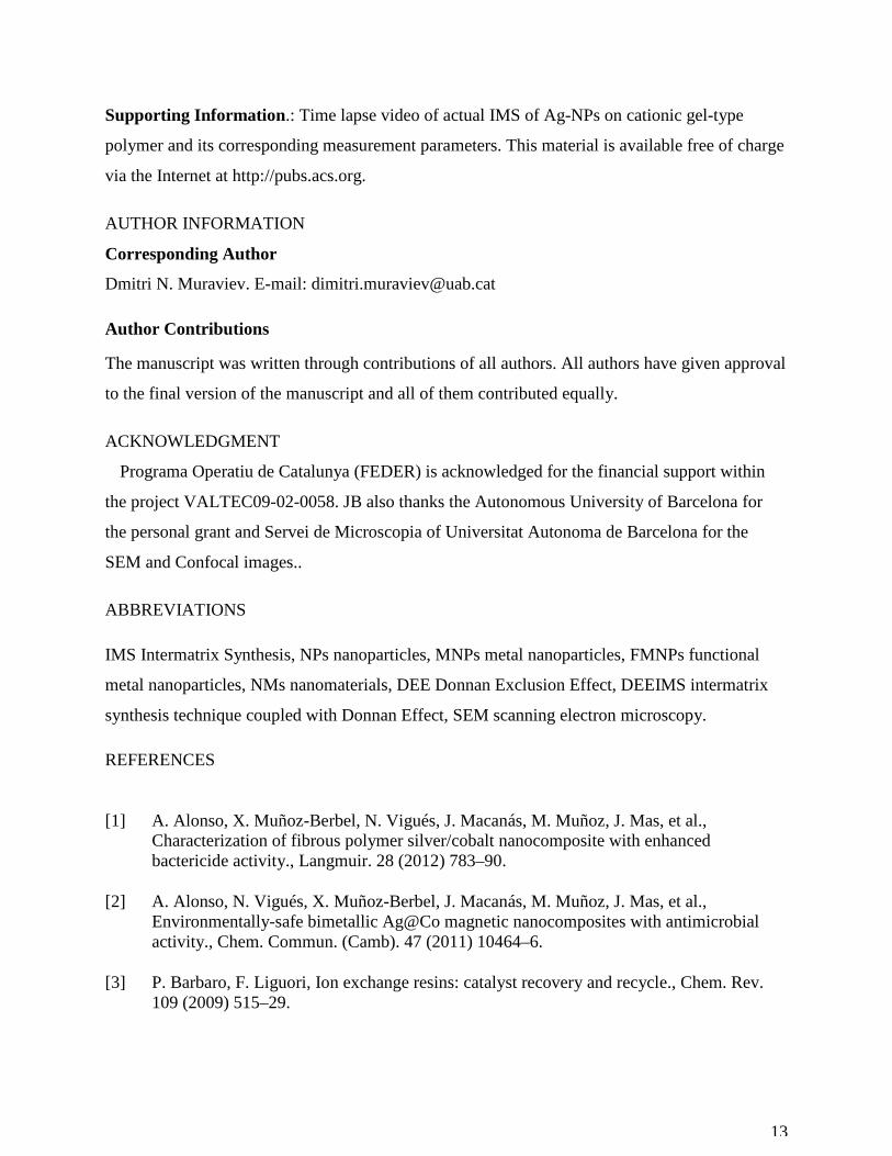
13
Supporting Information .: Time lapse video of actual IMS of Ag-NPs on cationic gel-type
polymer and its corresponding measurement parameters. This material is available free of charge
via the Internet at http://pubs.acs.org.
AUTHOR INFORMATION
Corresponding Author
Dmitri N. Muraviev. E-mail: [email protected]
Author Contributions
The manuscript was written through contributions of all authors. All authors have given approval
to the final version of the manuscript and all of them contributed equally.
ACKNOWLEDGMENT
Programa Operatiu de Catalunya (FEDER) is acknowledged for the financial support within
the project VALTEC09-02-0058. JB also thanks the Autonomous University of Barcelona for
the personal grant and Servei de Microscopia of Universitat Autonoma de Barcelona for the
SEM and Confocal images..
ABBREVIATIONS
IMS Intermatrix Synthesis, NPs nanoparticles, MNPs metal nanoparticles, FMNPs functional
metal nanoparticles, NMs nanomaterials, DEE Donnan Exclusion Effect, DEEIMS intermatrix
synthesis technique coupled with Donnan Effect, SEM scanning electron microscopy.
REFERENCES
[1] A. Alonso, X. Muñoz-Berbel, N. Vigués, J. Macanás, M. Muñoz, J. Mas, et al., Characterization of fibrous polymer silver/cobalt nanocomposite with enhanced bactericide activity., Langmuir. 28 (2012) 783–90.
[2] A. Alonso, N. Vigués, X. Muñoz-Berbel, J. Macanás, M. Muñoz, J. Mas, et al., Environmentally-safe bimetallic Ag@Co magnetic nanocomposites with antimicrobial activity., Chem. Commun. (Camb). 47 (2011) 10464–6.
[3] P. Barbaro, F. Liguori, Ion exchange resins: catalyst recovery and recycle., Chem. Rev. 109 (2009) 515–29.
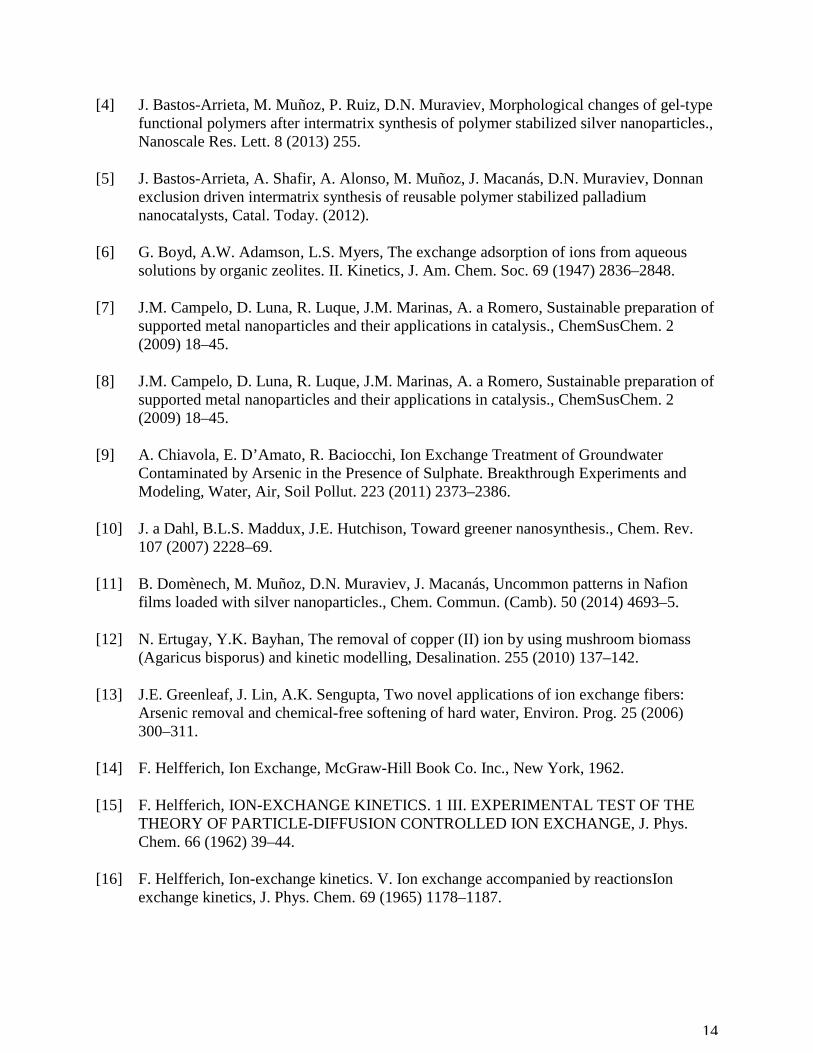
14
[4] J. Bastos-Arrieta, M. Muñoz, P. Ruiz, D.N. Muraviev, Morphological changes of gel-type functional polymers after intermatrix synthesis of polymer stabilized silver nanoparticles., Nanoscale Res. Lett. 8 (2013) 255.
[5] J. Bastos-Arrieta, A. Shafir, A. Alonso, M. Muñoz, J. Macanás, D.N. Muraviev, Donnan exclusion driven intermatrix synthesis of reusable polymer stabilized palladium nanocatalysts, Catal. Today. (2012).
[6] G. Boyd, A.W. Adamson, L.S. Myers, The exchange adsorption of ions from aqueous solutions by organic zeolites. II. Kinetics, J. Am. Chem. Soc. 69 (1947) 2836–2848.
[7] J.M. Campelo, D. Luna, R. Luque, J.M. Marinas, A. a Romero, Sustainable preparation of supported metal nanoparticles and their applications in catalysis., ChemSusChem. 2 (2009) 18–45.
[8] J.M. Campelo, D. Luna, R. Luque, J.M. Marinas, A. a Romero, Sustainable preparation of supported metal nanoparticles and their applications in catalysis., ChemSusChem. 2 (2009) 18–45.
[9] A. Chiavola, E. D’Amato, R. Baciocchi, Ion Exchange Treatment of Groundwater Contaminated by Arsenic in the Presence of Sulphate. Breakthrough Experiments and Modeling, Water, Air, Soil Pollut. 223 (2011) 2373–2386.
[10] J. a Dahl, B.L.S. Maddux, J.E. Hutchison, Toward greener nanosynthesis., Chem. Rev. 107 (2007) 2228–69.
[11] B. Domènech, M. Muñoz, D.N. Muraviev, J. Macanás, Uncommon patterns in Nafion films loaded with silver nanoparticles., Chem. Commun. (Camb). 50 (2014) 4693–5.
[12] N. Ertugay, Y.K. Bayhan, The removal of copper (II) ion by using mushroom biomass (Agaricus bisporus) and kinetic modelling, Desalination. 255 (2010) 137–142.
[13] J.E. Greenleaf, J. Lin, A.K. Sengupta, Two novel applications of ion exchange fibers: Arsenic removal and chemical-free softening of hard water, Environ. Prog. 25 (2006) 300–311.
[14] F. Helfferich, Ion Exchange, McGraw-Hill Book Co. Inc., New York, 1962.
[15] F. Helfferich, ION-EXCHANGE KINETICS. 1 III. EXPERIMENTAL TEST OF THE THEORY OF PARTICLE-DIFFUSION CONTROLLED ION EXCHANGE, J. Phys. Chem. 66 (1962) 39–44.
[16] F. Helfferich, Ion-exchange kinetics. V. Ion exchange accompanied by reactionsIon exchange kinetics, J. Phys. Chem. 69 (1965) 1178–1187.
15
[17] a. a. Kudinov, Y. V. Solodyannikova, O. V. Tsabilev, D. V. Obukhov, Deoxygenation of chemically purified water at thermal power plants, Power Technol. Eng. 43 (2009) 131–134.
[18] S. Kumar, S. Jain, History, Introduction, and Kinetics of Ion Exchange Materials, J. Chem. 2013 (2013) 1–13.
[19] D. Muraviev, J. Macanas, M. Farre, M. Munoz, S. Alegret, Novel routes for inter-matrix synthesis and characterization of polymer stabilized metal nanoparticles for molecular recognition devices, Sensors Actuators B Chem. 118 (2006) 408–417.
[20] D.N. Muraviev, Inter-matrix synthesis of polymer stabilised metal nanoparticles for sensor applications, Contrib. to Sci. 3 (2005) 19–32.
[21] B. Pan, B. Pan, W. Zhang, L. Lv, Q. Zhang, S. Zheng, Development of polymeric and polymer-based hybrid adsorbents for pollutants removal from waters, Chem. Eng. J. 151 (2009) 19–29.
[22] V. Polshettiwar, R. Luque, A. Fihri, H. Zhu, M. Bouhrara, J.-M. Basset, Magnetically Recoverable Nanocatalysts., Chem. Rev. (2011).
[23] N. Ramzan, N. Feroze, M. Kazmi, M. Ashraf, S. Hasan, Performance analysis of cation and anion exchangers in water treatment plant: an industrial case study, Polish J. Chem. Technol. 14 (2012) 35–41.
[24] J. Shi, On the synergetic catalytic effect in heterogeneous nanocomposite catalysts, Chem. Rev. 113 (2013) 2139–2181.
[25] P. Taylor, H. Matsuzuru, Y. Wadachi, Journal of Nuclear Science and Influence of Differences in Resin-Matrix Structure on Ion-Exchange Adsorption of Trace Amounts of Ag ( I ), Co ( II ) and Cr ( III ) Influence of Differences in Resin-Matrix Structure on Ion-Exchange Adsorption of Trace Amou, J. Nucl. Sci. Technol. 12 (1975) 344–349.
[26] P. Xu, X. Han, B. Zhang, Y. Du, H.-L. Wang, Multifunctional polymer-metal nanocomposites via direct chemical reduction by conjugated polymers., Chem. Soc. Rev. 43 (2014) 1349–60.
[27] E. V. Zolotukhina, T. a. Kravchenko, Synthesis and kinetics of growth of metal nanoparticles inside ion-exchange polymers, Electrochim. Acta. 56 (2011) 3597–3604.

16

17
Figure Captions
Figure 1: (a) High resolution SEM image of nanocomposite bead cross section and (b, c) Line
Scan EDS spectra showing distribution of Ag-MNPs (red) in sulfonic gel type cation-exchange
resin modified with Ag-FMNPs.
Figure 2: High-resolution SEM images of: a) NPs free granulated polymer. b, c, d, e, f): Ag-
FMNPs containing polymer with clearly seen as worm-like structure of nanocomposite surface
and nanopores. Magnification a = b < c < d< e < f
Figure 3: High–Resolution SEM images of Ag-FMNPs with an average diameter of 33±1nm.on
gel type polymer, show distribution of the FMNPs with non-evident agglomerates after surface
modification Magnification of b>>>a.
Figure 4: SEM images of cross sections of Ag-FMNPs-sulfonic gel-type polymer
nanocomposite granules at different times of metal loading stage and thicknesses (∆l) of final
FMNPs layer (time of a<b).
Figure 5: Thickness of FMNPs layer versus metal loading time.
Figure 6: Breakthrough curves of displacement of Na+ with Ca2+ from FMNPs-free sulfonic
cation-exchange resin and nanocomposites obtained after different times of metal loading stage.

18
Area marked by dotted lines corresponds to ion exchange capacity of resin and nanocomposite
samples.
Figure 7: Breakthrough curves of displacement of OH- with Cl- ions from FMNPs-free
quaternary amine anion-exchange resin (gray) and nanocomposite (dark gray) obtained by
DEEIMS technique with metal loading time of 1 minute.
19
Fiigures
Figure 1
Figure 2:
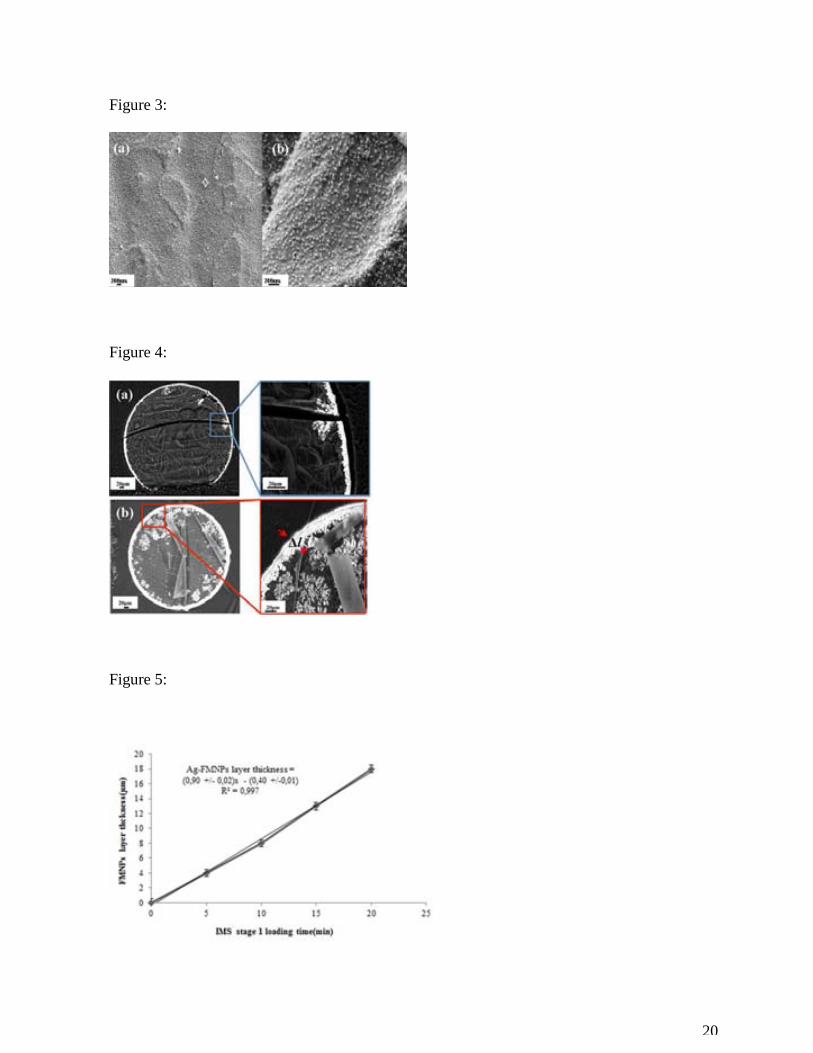
20
Figure 3:
Figure 4:
Figure 5:

21
Figure 6:
Figure 7:
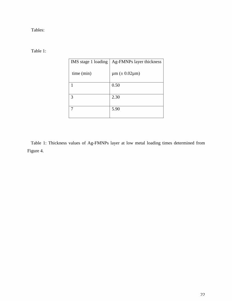
22
Tables:
Table 1:
IMS stage 1 loading
time (min)
Ag-FMNPs layer thickness
µm (± 0.02µm)
1 0.50
3 2.30
7 5.90
Table 1: Thickness values of Ag-FMNPs layer at low metal loading times determined from
Figure 4.
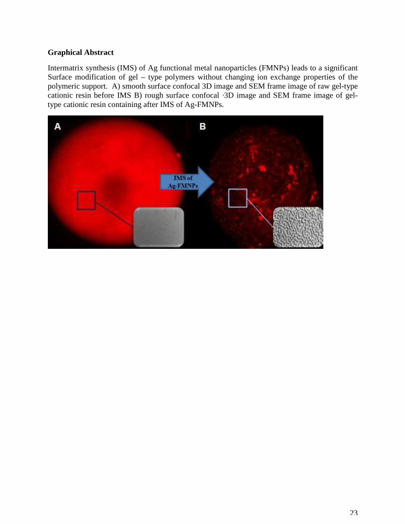
23
Graphical Abstract
Intermatrix synthesis (IMS) of Ag functional metal nanoparticles (FMNPs) leads to a significant Surface modification of gel – type polymers without changing ion exchange properties of the polymeric support. A) smooth surface confocal 3D image and SEM frame image of raw gel-type cationic resin before IMS B) rough surface confocal ·3D image and SEM frame image of gel-type cationic resin containing after IMS of Ag-FMNPs.