bilgin 145 new construction semi … · 2.2 material specifications 4 2.3 fuel tanks ... 3.6 chain...
TRANSCRIPT

BILGIN 145’ NEW CONSTRUCTION SEMI DISPLACEMENT YACHT SPECIFICATIONS
1. GENERAL 1
1.1 DEFINITIONS 1
1.2 INTENT 1
1.3 TYPE OF VESSEL 1
1.4 DIMENSIONS AND GENERAL SPECIFICATIONS 1
1.5 BRIEF DESCRIPTION 2
1.6 PERFORMANCE AND DESIGN 2
1.7 PLANS 2
1.8 ARTICLES SUPPLIED BY THE OWNER 2
1.9 MATERIALS AND WORKMANSHIP 2
1.10 INSPECTION 2
1.11 CARE OF VESSEL 3
1.12 TESTS 3
1.13 INCLINING EXPERIMENT 3
1.14 DOCK TRIAL 3
1.15 SEA TRIAL 3
1.16 ACCEPTANCE AND DELIVERY 3
1.17 CERTIFICATES, MANUALS AND REPORTS 4
1.18 SPARE PARTS 4
2 GENERAL FIBERGLASS CONSTRUCTION 4
2.1 GENERAL 4
2.2 MATERIAL SPECIFICATIONS 4
2.3 FUEL TANKS 5
2.4 GREY & BLACK WATER TANK 5
2.5 FRESH WATER TANK 5
2.6 LUBE OIL TANKS 5
2.7 BULWARK 5
2.8 RUBBING STRAKE 5
3. HULL AND SUPERSTRUCTURE FITTINGS 5
3.1 PORTLIGHTS 5
3.2 WINDOWS 5
3.3 HATCHES 5
3.4 SCUPPERS AND FREEING PORTS 6
3.5 EXTERNAL DOORS 6
3.6 CHAIN LOCKER 6
3.7 TENDER STORAGE 6
3.8 JET-SKI STORAGE 6
4. DECK FITTINGS AND EQUIPMENT 6
4.1 ANCHOR-WINCH AND CAPSTANS 7
4.2 ANCHOR AND CHAIN 7
4.3 DOORS IN BULWARK 7
4.4 LIFE RAFT AND SAFETY EQUIPMENT 7
4.5 CLEATS AND FAIRLEADS 7
4.6 FLAG POLES 7
4.7 MAST 7
4.8 COVERS 8
4.9 STORAGE FOR FIRE AND DECK-EQUIPMENT 8
4.10 DECK INVENTORY 8
4.11 STORAGE CHOCKS 8
5. MACHINERY 8
5.1 GENERAL 8
5.2 PROPULSION 8
5.2.1 MAIN ENGINES 8
5.2.2 GEARBOXES 8
5.2.3 PROPELLERS 8
5.2.4 STERN TUBE 9
5.2.5 SHAFT 9
5.2.6 RUDDERS 9
5.2.7 STEERING GEAR 9
5.3 FLEXIBLE MOUNTINGS 9
5.4 EXHAUST LINES 9
5.5 CONTROLS 9
5.6 INSTRUMENTATION 9
5.7 GENERATING SETS 9
5.8 STABILIZER & THRUSTERS 10
5.9 TRIM TABS 10
6. PIPING ARRANGEMENTS AND PUMPING SYSTEMS 10
6.1 COOLING WATER SYSTEM ENGINES 10
6.2 FUEL SYSTEM 10
6.3 BILGE AND DECK WASH SYSTEM 11
6.4 HYDRAULIC SYSTEM 11
6.5 FRESH WATER SYSTEM 11
6.6 TOILET SYSTEM 12
6.7 GREY WATER SYSTEM 12
7. VENTILATION 12
7.1 ENGINE ROOM 12
7.2 ACCOMMODATION 12
7.3 MAIN ENGINES 12
7.4 GENERATOR SETS 12
7.5 BATTERY SETS 12
8. AIR CONDITIONING 13
8.1 GENERAL AND CAPACITY 13
8.2 COOLING UNITS 13
8.3 PIPELINES 13
9. ENGINE ROOM VARIOUS 13
9.1 FIRE-FIGHTING SYSTEM 13
9.2 WORK BENCH 13
9.3 FLOORING 14
9.4 GUARDS 14
9.5 RAILING 14
9.6 MARKING 14
9.7 SINK 14
9.8 STORAGE TANKS 14

10. INSULATION AND SOUND PROOFING 14
11 ELECTRICAL INSTALLATION 15
11.1 GENERAL 15
11.2 ELECTRIC CABLE AND WIRING 15
11.3 MAIN ELECTRICAL SYSTEM 380 VOLT, 50 HZ 15
11.4 LOW VOLTAGE SYSTEM 24 VOLT DC 15
11.5 BATTERIES AND CHARGING 16
11.6 MAIN SWITCH BOARD 380 VOLT, 50 HZ, 3 PHASE 16
11.7 OUTGOING CIRCUITS 17
11.8 DISTRIBUTION PANEL 17
11.9 LIGHTING, ACCOMMODATION AND ENGINE ROOM 17
11.10 ALARMS 18
11.11 FIRE-DETECTION SYSTEM 18
11.12 EXTERIOR-LIGHTING 18
11.13 NAVIGATION LIGHTS 18
11.14 SHORE CONNECTIONS 18
12. NAVIGATION AND WHEELHOUSE EQUIPMENT 19
12.1 GENERAL 19
12.2 COMMUNICATION EQUIPMENT 19
12.2.1 SART (SRH Radar Transponder) 19
12.2.2 INTERCOM TELEPHONE SYSTEM 19
12.2.3 EPIRB 19
12.2.4 LOUDHAILER 19
12.3 NAVIGATION EQUIPMENT 19
12.3.1 MAGNETIC COMPASSES (MAIN HELM / FLYBRIDGE) 19
12.3.2 WIND SPEED DIRECTION METER 19
12.4 TELEPHONE SYSTEM 19
12.5 HORN 19
12.6 WINDSCREEN WIPERS AND WASHERS 19
12.7 SEARCH LIGHTS 19
13. ACCOMMODATION 20
13.1 INTERIOR 20
13.2 LAY-OUT 20
13.3 DETAILING AND QUALITY 20
13.4 EXTERIOR MAIN DECK 20
13.5 EXTERIOR FLYING BRIDGE 20
13.6 FRESH WATER MAKER 20
13.7 GANGWAY & CRANE 20
13.8 HYDRAULIC SYSTEMS FOR JETSKI LIFTING 20
13.9 CCTV SYSTEM 20
13.10 GALLEY APPLIANCES 20
13.11 OUTDOOR FLOORING 20
13.12 ENTERTAINMENT 20
Page 1
1. GENERAL
1.1 DEFINITIONS
"The Builder" refers to the company that is contracted to build the yacht as described in
this specification.
"The Owner" refers to the person or company who (which) contracted the Builder for the
construction of the yacht as described in this specification.
1.2 INTENT
It is the intent of this specification, plans, and addendum to the specification, and contract
so the Builder shall construct, equip and furnish a yacht complete and ready for service
according to the classification society and flag state of the yacht
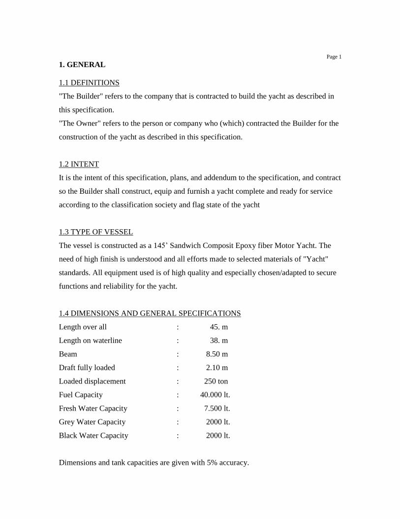
1.3 TYPE OF VESSEL
The vessel is constructed as a 145’ Sandwich Composit Epoxy fiber Motor Yacht. The
need of high finish is understood and all efforts made to selected materials of "Yacht"
standards. All equipment used is of high quality and especially chosen/adapted to secure
functions and reliability for the yacht.
1.4 DIMENSIONS AND GENERAL SPECIFICATIONS
Length over all : 45. m
Length on waterline : 38. m
Beam : 8.50 m
Draft fully loaded : 2.10 m
Loaded displacement : 250 ton
Fuel Capacity : 40.000 lt.
Fresh Water Capacity : 7.500 lt.
Grey Water Capacity : 2000 lt.
Black Water Capacity : 2000 lt.
Dimensions and tank capacities are given with 5% accuracy.
Page 2
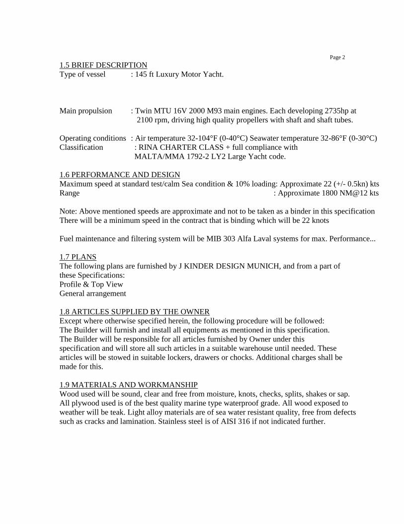
1.5 BRIEF DESCRIPTION
Type of vessel : 145 ft Luxury Motor Yacht.
Main propulsion : Twin MTU 16V 2000 M93 main engines. Each developing 2735hp at
2100 rpm, driving high quality propellers with shaft and shaft tubes.
Operating conditions : Air temperature 32-104°F (0-40°C) Seawater temperature 32-86°F (0-30°C)
Classification : RINA CHARTER CLASS + full compliance with
MALTA/MMA 1792-2 LY2 Large Yacht code.
1.6 PERFORMANCE AND DESIGN
Maximum speed at standard test/calm Sea condition & 10% loading: Approximate 22 (+/- 0.5kn) kts
Range : Approximate 1800 NM@12 kts
Note: Above mentioned speeds are approximate and not to be taken as a binder in this specification
There will be a minimum speed in the contract that is binding which will be 22 knots
Fuel maintenance and filtering system will be MIB 303 Alfa Laval systems for max. Performance...
1.7 PLANS
The following plans are furnished by J KINDER DESIGN MUNICH, and from a part of
these Specifications:
Profile & Top View
General arrangement
1.8 ARTICLES SUPPLIED BY THE OWNER
Except where otherwise specified herein, the following procedure will be followed:
The Builder will furnish and install all equipments as mentioned in this specification.
The Builder will be responsible for all articles furnished by Owner under this
specification and will store all such articles in a suitable warehouse until needed. These
articles will be stowed in suitable lockers, drawers or chocks. Additional charges shall be
made for this.
1.9 MATERIALS AND WORKMANSHIP
Wood used will be sound, clear and free from moisture, knots, checks, splits, shakes or sap.
All plywood used is of the best quality marine type waterproof grade. All wood exposed to
weather will be teak. Light alloy materials are of sea water resistant quality, free from defects
such as cracks and lamination. Stainless steel is of AISI 316 if not indicated further.
Page 3
1.10 INSPECTION
Unlimited access during normal working hours/Days with access to office facilities provided by
the builder. Visits outside normal working hours/Days only to by prior notice to the”builder”.
1.11 CARE OF VESSEL
The yacht will be built in a building suitable for Cold Molded constructions.
Vessel to be fully insured by the Builder up to acceptance and handover date.
1.12 TESTS
All work accomplished under this specification are thoroughly tested as specified or
directed to demonstrate satisfactory workmanship, suitability for the purpose intended
and that all requirements of the specifications have been satisfactorily fulfilled.
1.13 INCLINING EXPERIMENT
When the yacht has been practically completed and outfitted, the
Builder will make an inclining experiment. The Builder will provide the necessary personnel
and the equipment for the experiment to assist in doing so. Following inclining experiment,
stability book will be furnished and Approved by Class. Vessel is to meet, or exceed,
minimum stability values as required by Class and LY2 code for this type of vessel.
1.14 DOCK TRIAL
When the work specified herein has been sufficiently completed, the
Builder will conduct dock trials, during with all main and auxiliaries.
Machinery supplied and/or installed shall be thoroughly tested.
This includes main propulsion machinery to an acceptable level of power, taking into
consideration the facilities at the Builders Quay and the safety of the vessel.
1.15 SEA TRIAL
When all work specified herein has been practically completed, the Builder will conduct
sea trials under normal weather conditions, during with the operating of the vessel
including all machinery and equipment will be examined. All machinery and systems
usually operating under service conditions will be put into operation simultaneously and
continuously so far as practicable. This will involve the operation of deck machinery and
miscellaneous equipment. Speed trials will be held under fair weather conditions
(maximum Bf.2) and carried out with ca.10% filled tanks.
All navigation and communication equipments will be properly adjusted.
Tests will be according to the requirements of the Classification Society.

Page 4
1.16 ACCEPTANCE AND DELIVERY
When fully accepted by the Owner and all terms have been agreed by the Builder, the yacht
will be handed over to the Owner in ”showroom” condition. Which means vessel will be
delivered to the owner as it would be. Delivery will be at the ATAKOY Yacht Marina-
Istanbul. All Class & MMA interim certificates are to be issued prior to acceptance.
1.17 CERTIFICATES, MANUALS AND REPORTS
The following certificates will be supplied in duplicate upon delivery of the yacht. Where
not available a temporary certificate can be acceptable:
• Builder's certificate
• Classification certificate
• Certificate for lifesaving appliances.
*Certificate for Fire fighting appliances/installations
*IOPP Certificate + SOPEP
*Intl. Loadline Cert
*Intl Tonnage Cert
*Certificate of Registry
*Ships Radio Licence
*Certificate of compliance MMA-LY2 code.
*Stability booklet and Stability information (damaged condition)
In addition to the above, certificates required by the Classification Society will be supplied.
Registration of the vessel and duties are for account of the Owner.
Fuel consumption and speed report will be provided after measurement during trials by
the engine manufacturer.
All system drawings, wiring diagrams, piping plans, docking plan and tank capacity
tables and stability booklet will be provided as built.
All equipment handbooks relating to equipment installed aboard the vessel, electrical,
electronic, or mechanical, will be provided.
l. A list of all major equipment with model numbers, suppliers and other important
information will be supplied with the vessel
1.18 SPARE PARTS
Scope of supply according to Classification requirements.
Page 5
2 GENERAL CONSTRUCTIONS
2.1 GENERAL
Hull, decks, bulkheads, superstructure will be executed in Sandwich Composit Epoxy
fiber
2.2 MATERIAL SPECIFICATIONS
Hull and Superstructure construction
Hull material : Sandwich Composit Epoxy fiber
Superstructure : Sandwich Composit Epoxy fiber
Frames & Decks : Sandwich Composit Epoxy fiber
Outer skin & inner skins : AWLGRIP paint system
Superstructure outsideb : AWLGRIP paint system
Approved paint schedule, materials & application from AWLGRIP.
AWLGRIP representative to inspect and warranty on completion.
2.3 FUEL TANKS
Four (4) storage tanks and one (1) day tank with total capacity of 40.000 liters will be
placed in the engine room with isolation valves situated on the fuel manifold.
All tanks provided with swash plates, properly stiffened, manholes, fill pipes, ventilation
pipes, connection pipes to manifold, sounding system, etc.
The day tank will have Main Deck operated remote-controlled shut-off valve.
2.4 SEWAGE SYSTEM FOR GREY & BLACK WATER
Jets make or equivalent toilets and Hamann make sewage treatment system will be
installed to fully comply with MARPOL requirements.
2.5 FRESH WATER TANK
Two (2) integral stainless steel fresh water tanks provided with swash plate, manhole,
ventilation pipe, connection pipes to water pressure system and sounding system.
2.6 LUBE OIL TANKS
A fresh lube oil storage tank of 500lt. and a dirty lube oil tank of 500lt. will be installed.

Page 6
2.7 BULWARK
Filling stations for fuel and fresh water will be placed on main deck level outside the
superstructure. These stations will be executed in such a way that they are in compliance
with applicable MMA rules against pollution.
2.8 RUBBING STRAKE
Profile as indicated on the profile drawing. The profile will be protected by means of a
stainless steel strip.
3. HULL AND SUPERSTRUCTURE FITTINGS
3.1 PORTLIGHTS
Stainless steel portholes of rectangular and round shape with rounded corners, and clear
safety glass. All portholes will be equipped with mosquito screens, dead light covers and
opening sensors. Number of portholes as indicated on plans.
3.2 WINDOWS
The windows in the superstructure are glued into the Cold Molded construction. All
windows will be safety glass. Wheelhouse front windows will be clear; all other windows
will be tinted dark grey.
3.3 HATCHES
• One (1) flush inspection hatch to forepeak.
• Escape hatches as per escape routes plan
3.4 SCUPPERS AND FREEING PORTS
Scupper pipes will be installed to provide proper drainage of all outside decks, drainage
to the boot top. Freeing ports as indicated on profile plan.
3.5 EXTERNAL DOORS
• Two (2) nos. stainless steel framed sliding door in aft bulkhead of
• Four (4) nos. of stainless steel pantograph doors for side boarding on main deck and
upper deck
• All doors will be equipped with efficient locking system.
The aft saloon and owner’s deck aft door are to have hydraulic self opening system installed
Page 7
3.6 CHAIN LOCKER
A chain locker, located in the lower part of the forepeak with stainless steel chain pipe. A
durable rubber compound lining will be applied in internal hull structure in chain locker
to protect hull and bulkheads. The chain locker will be suitably drained.
3.7 TENDER STORAGE
On fly bridge deck a free space, suitable for a 17’ rigid inflatable tender is provided.
Launching by means of a hydraulic crane.
3.8 JET-SKI STORAGE
On fly bridge deck a free space, suitable for Jet Ski’s is provided.
Launching by means of the hydraulic crane as used for the Tender.
4. DECK FITTINGS AND EQUIPMENT
4.1 ANCHOR-WINCH AND CAPSTANS
Two (2) MUIR make hydraulic anchor-winch or equivalent, capacity & size as per calculation
of manufacturer & Naval Architect for the foredeck with deck foot switches.
The winch is of the vertical-shaft type and equipped with capstan head.
Two MUIR make hydraulic vertical capstan or equivalent as per calculation of manufacturer &
Naval Architect for the aft deck with deck foot switches to operate the capstans.
4.2 ANCHOR AND CHAIN
Two (2) BRILLMAR make Stainless Steel anchor with stainless steel lined anchor roller.
Two (2) sets of 150mtr. Galvanized short link chain-cable U2 grade of 18 mm diameter
will be supplied. Last link of chain will be fastened securely in the chain locker with an
emergency release.
4.3 DOORS IN BULWARK
Two (2) Stainless Steel doors provided with stainless steel hardware. A stainless steel
gate will protect the stairs leading to the swimming platform.
4.4 LIFE RAFT AND SAFETY EQUIPMENT
All safety equipment to meet MMA LY2 code requirements, and be MMA approved and
properly installed and stowed.
• Two (2) 16 person life raft in fiberglass container will be supplied and installed on fly-bridge deck,
Requirement is for sufficient liferaft capacity for the total crew and passengers to be carried on
EACH side of the boat, unless mounted in the middle of the vessel, and capable of being launched
easily from either side.
Page 8
12 guests and 9 crew on board.
• Two (2) 24” life saving rings in aluminum brackets to be supplied and installed, on each
deck. Two with MOB lights, two with ropes, and two located immediately outside bridge
on each wing equipped with smoke/float.
• SOLAS approved (22) adult life preservers and ten (10) for children to be supplied.
• Suitably approved offshore Medical kit.
• Fire blanket for galley, aft crew quarters and engine room.
• Dry chemical Fire Extinguishers to be installed in suitable locations;
4.5 CLEATS AND FAIRLEADS
Stainless Steel cleats, two (2) on foredeck, two (2) on aft deck and four (4) amidships.
Necessary cleats for fender lines will be fitted Oval fairleads at sides in bulwark as shown
on profile drawing. Fairleads will be finished with stainless steel.
4.6 FLAG POLES
• Flag pole on main deck aft, made of stainless steel, with halyard, cleat etc.
• Flag pole on bow.
4.7 MAST
Aluminum mast as shown on General Arrangement Plan and provided with:
• Platform for radar and aerials, combined with signal halyards, cleats and masthead-light platform.
• Flood Light
• Built-in deck lights in underside
• KAHLENBERG T2 air Signal Horn
• One anchor light
• One (1) Searchlight, remote controlled.
Page 9
4.8 COVERS
Dacron or equal covers will be supplied for anchor winch, wheelhouse windows, and
outside cushions, etc.
4.9 STORAGE FOR FIRE AND DECK-EQUIPMENT
Suitable places for storage of hoses will be provided on fore- and aft deck. Adequate
storage for fenders, lines, boat hooks and cleaning supplies in deck locker forward and in
deck benches on boat- and aft deck.
4.10 DECK INVENTORY
The following items will be supplied and installed and stowing arrangements are provided for:
• Four (4) mooring lines, braided black nylon, 1" diameter, 100 ft / 30m. each.
• Six (6) PVC inflatable fenders with Dacron covers, size 15" x 40" (208x1000 mm).
• Two (2) aluminum boat hooks, telescopic type.
4.11 STORAGE CHOCKS
Tender, wave runners and all types of toys are to be supplied by the Owner.
5. MACHINERY
5.1 GENERAL
All machinery will be installed to manufacturer’s requirements and according to
Classification Society and MMA requirements. Flexibility of all connecting pipes, cables,
hoses and shafts will be matching to the flexibility of the supports of the equipment.
Pumps and parts will be standardized wherever possible.
5.2 PROPULSION
Engines will be equipped with fresh water cooling, heat exchanger, seawater pump, oil
cooler and oil drain pump. Engine installation as per engine manufacturer.
5.2.1 MAIN ENGINES
Make : Twin MTU 12V 4000 M93
Max. Output : 2735hp at 2100 RPM.
5.2.2 GEARBOXES
Make : ZF Marine
Type : pleasure duty
Reduction Ratio : up on Naval Architect calculation
5.2.3 PROPELLERS
Two (2) Eliche & Radice Copper Nickel Aluminum propellers, diameter apprx. 48” (1220 mm)
Page 10
5.2.4 STERN TUBE.
Stern tube to be fitted with water-lubricated bearings, fitted with a self aligning inner
seal, make Tides Marine or similar
5.2.5 SHAFT
Eliche & Radice make 90mm Duplex S.St shaft made of Aquamet 22 or equiv.
5.2.6 RUDDERS
Twin spade rudders, made of Stainless Steel, with Aquamet 22 or equivalent rudderstock.
Dimensions and execution as indicated by the designer and classification society
5.2.7 STEERING GEAR
KOBELT make Equipment or equivalent, twin rudder full servo hydraulic powered steering
gear, providing torque over 2x 35 degrees rudder angle. In main steering station. An
emergency steering system is to be installed consisting of one (1) manual hydraulic helm
pump system and emergency tiller arm. Dimensions and execution in accordance with the
requirements of Classification Society.
5.3 FLEXIBLE MOUNTINGS
Generator sets will be resilient mounted. Engines will be mounted on flexible mountings.
All pipe connections to engines have flexible parts.
Torsional vibration will be minimized and choice of mounts will be in accordance with
the requirements of the Classification Society.
The main engine supplier will carry out Torsional Vibration Calculation for the
propulsion train.
Electrical motors will be resilient mounted.
5.4 EXHAUST LINES
Main engines to be equipped with water-injected exhaust pipes through sides near transom.
Generator sets are equipped with water-injected exhausts and mufflers.
All exhausts/discharges to meet MARPOL Annex VI requirements re emissions.
Discharge through ship's sides.
Materials: Stainless steel AISI 316L pipe and compensators.
5.5 CONTROLS
Propulsion engines will be controlled from wheelhouse & two wing stations on
wheelhouse deck.
5.6 INSTRUMENTATION
The yacht will be equipped with freetechnics make alarm & automation integrated
electronic monitoring system for propulsion units, generator sets, bilge alarm, fire alarm,
tank contents, etc. Monitored in Wheelhouse and aft crew cabin
Page 11
5.7 GENERATING SETS
Two synchronized marine diesel generator sets 380v 3 phase @ 50 Hz. Sizes per electric
load calculations Make ONAN or Koehler
5.8 STABILIZER & THRUSTERS
TRAC make Hydraulic Bow & Stern thrusters and stabilizer as per Naval Architect
Calculations be installed. A protective grid for thrusters will be fitted.
5.9 TRIM TABS
The yacht will be equipped with trim tabs with indicators on main & fly bridge stations. The trim
tabs’ setting is adjusted by hydraulic cylinders. Manual controls to be fitted in the wheelhouse.
6. PIPING ARRANGEMENTS AND PUMPING SYSTEMS
Piping will be internationally color-coded and indicate flow direction.
6.1 COOLING WATER SYSTEM ENGINES
• Main and auxiliary engines will have fresh water cooling systems with heat exchangers,
oil cooler and seawater pumps.
• Two (2) large seawater inlets with crossover facility.
• Valves and filters will be fitted.
• Pipelines will be CuNiFer or stainless steel for sea water lines.
• Flexible connections to engines through best quality rubber hoses with double stainless
steel clips on both ends.
• Seawater inlet strainers will have isolation valves, are easy accessible and quickly cleaned.
6.2 FUEL SYSTEM
• Fuel storage tanks with sounding system.
• Fuel day tank with sounding system and high and low level alarm.
• Tanks have a centralized filling station on main deck side. All tanks vented to main deck level.
• One (1) electric transfer pump 380V/3-phase will be installed. The fuel transfer pump
will be auto OFF but manual ON. The fuel transfer pump will be suitable for diesel
• One emergency hand pump.
• Fuel transfer from storage tanks to day tank will be monitored through a flow meter.
• Fuel lines will be made of stainless steel pipes, connections to engines and auxiliary by
flexible hoses.
• All valves will be ball-type.
• Racor filters with alarm will be installed for both engines and generators. Alfa Laval fuel purifier system to clean the fuel before being transferred to day tank.

Page 12 6.3 BILGE AND DECK WASH SYSTEM
Provisions will be made to ensure unobstructed flow of bilge water to suction outlets of
the bilge system.
• One (1) electric self-priming bilge/general service pump, 380V 3-phase.
• One (1) same electric self-priming bilge pump, 380V 3-phase as back up.
• One (1) emergency hand pump.
One of the bilge pumps so arranged that it can serve bilge system or fire fighting system
while second can serve bilge system only.
Pumps draw from a bilge valve chest and discharge overboard.
In the accommodation PVC suctions lines 1 1/4" (38 mm) will be fitted and in the engine
room Cunifer or Stainless Steel pipes to be fitted.
All bilge suctions provided with storm boxes.
Bilge alarm system will be installed.
6.4 HYDRAULIC SYSTEM
The general hydraulic system will be driven by main engine driven hydraulic pumps and
provides power for bow & stern thruster, anchor winch, aft capstan and stabilizer system
6.5 FRESH WATER SYSTEM
• One (1) electric air pressure tank for fresh water supply, 380V/3-phase pump, and an
emergency 24V DC pump will be fitted.
• Filters will be installed at suction side.
*Silver ION (Iodide) treatment system fitted in shorewater supply line.
• Fresh water tank in bilge with low-level alarm gauges.
• Filling and ventilation lines to side deck.
• For domestic hot water supply, three (3) isotherm make electric water heaters of 100 ltr. Capacity
each will be installed.
• Cold and hot water lines will be made of polypropylene
• Hot water lines will be well insulated. Hot water system to be recirculating type.
• Dock connection for shore water supply on aft swimming platform, with pressure reducer.
Page 13
• Fore, aft and on boat deck outlets for wash down plus wash down outlets on
Wheelhouse deck fore & aft. Aft Jet Ski locker
• One handheld shower with hot and cold water on swimming platform in a suitable place.
6.6 TOILET SYSTEM
Jests Toilet System and Hamann Sewage System with shore connection for pump out
from black water tank to fully comply with MARPOL requirements.
6.7 GREY WATER SYSTEM
The grey water will be connected to the Hamann Sewage treatment System.
7. VENTILATION
7.1 ENGINE ROOM
• One reversible axial-flow fan with suitable capacity and with suitable air ducts will be
installed to ensure evenly distributed air to the engine room. Engine room temperature to
be maximum 115°F (50°C) at 95°F (32°C) outside temperature.
• Fans can be stopped in an emergency with switches mounted above main deck level
near the engine-room entrance and in the wheelhouse.
• All ventilation openings are equipped with fire-flaps. Flap controls, fuel shut-offs,
ventilation shut-offs, CO2 release to be located in same emergency panel.
7.2 ACCOMMODATION
• Galley and bathrooms will have mechanical air exhaust, central system, providing air
change 1 in 6 minutes in galley and in bathrooms.
• The blowers are 220 Volt, 50Hz, 3 phase
7.3 MAIN ENGINES
The main engine combustion air is taken from the engine room. Filter arrangements
according to engine manufacturers' requirements.
7.4 GENERATOR SETS
The generator sets draw their combustion air from the engine room.
7.5 BATTERY SETS
Adequate ventilation will be ensured for the batteries.
Page 14 8. AIR CONDITIONING
8.1 GENERAL AND CAPACITY
Cruise-Air make Marine type chilled water Air conditioning system and fresh air make
up system will be installed according to manufacturers' requirements. All compressors,
fans etc. are 380V/3-phase @ 50Hz.
Suitable capacity will be calculated by manufacturer
8.2 COOLING UNITS
Sufficient and well balanced throughout accommodation.
Each space will be equipped with separate controls.
Control panels with frequency control, to ensure low-noise levels.
Condensation water will be discharged to waste water tank. Drains in aft side of
condensation collector pan.
8.3 PIPELINES
UPVC pipes will be used. To class rules
9. ENGINE ROOM VARIOUS
9.1 FIRE-FIGHTING SYSTEM
• A fire extinguishing system will be installed with the necessary nozzles and a trigger
outside the engine room (near the entrance).
• Manufacturer's instructions will be strictly observed.
• Life saving NOVEC 1230 fire fighting system will be installed
• A siren in the engine room is operating automatically when fire alarm is activated.
• Instruction plate near triggers.
9.2 WORK BENCH
• A light workbench will be installed in engine room with worktop of wood.
• Vice of forged steel.
• Near workbench outlets of 220V AC & 380V AC.
• Storage space for spare parts etc.
• Adequate storage lockers for tools and spare parts will be provided.
Page 15 9.3 FLOORING
• Flooring of FRP checkered plates, or mesh flooring on stairs and other areas.
• Plates will be fastened.
• Where necessary removable sections in way of valves, filters, batteries, etc.
• Flooring system will be rattling free.
9.4 GUARDS
Guard plates will be positioned in way of revolving machinery and current carrying parts,
especially regarding starting motors.
9.5 RAILING
A stainless steel railing will be fitted around the main engines.
Additional handrail locations to be provided where deemed necessary.
9.6 MARKING
All valves, cocks, filters, pumps, etc. will be marked
9.7 SINK
Sink with water faucet will be installed in engine room.
Rubber hose for filling of cooling water system of main and auxiliary engines.
9.8 STORAGE TANKS
A fresh lube oil storage tank of 150 gallon will be installed. A dirty lube oil tank of 150
gallon will be installed. Both tanks will be incorporated in the bottom structure.
A suitable discharge system with portable electric pumps and hose connections will be
provided. A discharge flange is mounted on main deck level.
Lube oil transfer pump will be fixed not removable
To fully comply with MARPOL, Class requirements
10. INSULATION AND SOUND PROOFING
Rockwell make rockwool for insulation and soundproofing conform to Insulation Plan
with Double of engine room insulation especially of the forward bulkhead where the
master room situated
Get sound measures
Target dBA levels
When the main engines are secured and one engine room exhaust fan, the air
conditioning system, galley exhaust fan and one generator are operating, the sound levels
shall not exceed:
Aft Deck 80 db
Main Saloon 60 db
Client's Cabin 55 db
Guest Quarters 60 db

Page 16
Cruising with main engines @1800rpm, one engine room exhaust fan, the air
conditioning system, galley exhaust fan and one generator are operating, the sound levels
shall not exceed:
Aft Deck 85 db
Main Saloon 65 db
Client's Cabin 60 db
Guest Quarters 65 db
11 ELECTRICAL INSTALLATION
11.1 GENERAL
The electrical installation over all, such as equipment, wiring and cables, fixtures,
labeling etc. is to be secured properly, and designed in such a manner, that maintenance
and repair can be carried out easily.
Nameplates in number, size, execution and text and execution of electrical panels to be of
good quality, clearly marked in English language.
All electrical equipment will be proven satisfactory for marine use.
During dock trials, after the yacht has been finished and launched, the installation and
generator sets are to be tested under full load conditions. In all living areas cables will be
concealed.
All outlets and switches to be laid-out with designer’s drawing
All outlets to be of 220V.
All electrical equipment shall be properly labeled and
11.2 ELECTRIC CABLE AND WIRING
All cables and wiring will be suitable for marine use.
All feeder cables for electronic equipment will be screened.
Special attention will be given to prevent radio-interference. For special systems (radar,
radio equipment, etc.), special cables as specified by the manufacturers of the system,
will be used.
Cables passing through watertight bulkheads and decks will be made watertight by means
of stuffing boxes and meet class requirements for penetrations.
Cables will be fixed to cable trays and fastened with metal clips and tierap bands, neatly
run, easily accessible and equipped with chafing gear where necessary.
The grounding circuit will be attached to electrical fixtures of fittings, to form a
continuous metallic system between all the electrical parts, switchboard and panels.
Page 17
11.3 MAIN ELECTRICAL SYSTEM 380 VOLT, 3 PHASE 50 HZ
The installation will be a 3-wire system, 3-phase, 380/220V, 50 Hz. Shore supply 1 x
380V/100 Amp, 3-phase Main power supplied by two (2) generator sets, each with a
capacity to be defined by Certified Electrical Engineer after load analyze calculation. One
power converter will allow operating the yacht in USA & Europe
11.4 LOW VOLTAGE SYSTEM 24 VOLT DC
The low voltage system to be 24 Volt DC, bipolar insulated with the necessary
Volt/Amp. meters and earth fault indication lamps. Panel in wheelhouse.
11.5 BATTERIES AND CHARGING
• One set of 24 Volt starting batteries, gel type, will be arranged for each main engine and
each generator set. Both banks for main engines inter connectable with switch.
• Capacity of starting batteries will be in accordance with the requirements of the
classification Society. A quick changeover system with two (2) battery switches and two
(2) keys with the general battery set to be arranged.
• These switches will be installed in a steel box as close as possible to the batteries. The
alternators on both main engines do the charging of the starting batteries.
• One emergency bank for electronics.
• One (1) general-service battery set 24 Volt, to be arranged for navigation lights,
auxiliary circuits, electronic/nautical equipment and 24 Volt DC lighting.
*Emergency battery supply to be provided for GMDSS equipment as per SOLAS
requirements, Class society, and MMA.
• Above-mentioned batteries will be charged by three battery chargers, capacity 75
Amps. The battery charger to be self-regulating and to be so arranged that the output
couldn’t exceed 27.6 Volt DC.
11.6 MAIN SWITCH BOARD 380 VOLT, 50 HZ, 3 PHASE
Main switchboard of the aluminum box type in the engine room. All devices will be
accessible from the front. Generally the main switchboard system will be equipped with
magnetic contactors, overload protections and short circuit protections.
Electrical panel with earth leakage indicator as well as alarm and ELCB
The 380/220 Volt system will be monitored from the main switchboard.

Page 18
The panel is equipped with the following apparatus for each generator:
• One (1 three positions switch (off-standby-running)
• One (1) Voltmeter with select switch
• One (1) frequency indicator.
• One (1) Ampere meter with current transformers.
• One (1) Watt meter
• One (1) signal light on.
• One (1) signal light alarm.
• One (1) signal light disconnect for the shore connection:
• One (1) Voltmeters with select switch.
• One (1) Ampere meters with current transformers.
• One (1) Phase sequence meter
• One (1) signal light connect
• One (1) signal light disconnect
• One (1) signal light shore energized for the bus bar system (to share the load) a transfer
switch system with signal lights with the following positions:
• Generator 1
• Generator 2
• Shore connection For the 24 Volt system:
• One (1) Voltmeter for the general service battery.
• One (1) Voltmeter with changeover switch for the startingbatteries.
• Two (2) Ampere meters (Charge/Discharge service batteries)
11.7 OUTGOING CIRCUITS
The outgoing circuits to be protected by circuit breakers, the starters for electric motors to be
of the magnetic type.
11.8 DISTRIBUTION PANEL
Secondary distribution panels are placed at:
• Main deck
• Galley
• Lower deck aft (crew)
• Lower deck
• Wheelhouse
Supply lines will be protected by automatic circuit breakers, suitable for short circuit and
overload protection.
Main panel in wheelhouse contain following:
• Navigation lights
• Deck lighting
• Navigation equipment

Page 19 11.9 LIGHTING, ACCOMMODATION AND ENGINE ROOM
The lighting systems will Cantalupi make. 2-pole installed partly 24 Volt DC and partly 220
Volt AC as will be directed by the Designers. Each cabin will be supplied with two (2)
circuits, lights on stairs and passages will be switched from two (2) positions, two (2) step
lights in each step.
Adequate number of 220V outlets to be provided.
Ample use of dimmers in interior lighting.
All lockers in State Rooms to have automatically switched lights.
Storage spaces below floors will have automatically switched lights.
Adequate lighting will be provided throughout the accommodation.
All lights with dimmer switches. The dimmer switches will be fitted one next to the bed and
the other next to the door entrance.
11.10 ALARMS
Alarm functions to be monitored:
• Bilge
• Day tank level high and low.
• Sewage tank level high and low
• Waste Water tank level high and low
• Fuel filter water
• Fresh water low level.
• Fuel oil storage tank low level
• Fire alarm with schematic position indication.
• Any other alarms, as required by the Classification Society
General alarm will be audible and visual indicated in Owner’s cabin and in crew's
quarters. FIRE, General Alarm and/or PA system to meet MMA requirements.
Navigation lights, Port holes, aft doors, Audile in Aft/forward crew quarters and
wheelhouse.
11.11 FIRE-DETECTION SYSTEM
In all accommodation spaces (Including galley) and in the engine room
smoke alarms and heat sensors will be fitted. Monitoring panel in wheelhouse.
All in compliance with the requirements of the classification society.
11.12 EXTERIOR-LIGHTING
Flood light forward on the centreline and on the arch, to illuminate
superstructure. Switches in the pilothouse. Exterior lighting will be
waterproof, good marine quality. Remaining exterior lighting will be
indicated by the Designers. In general a proper lighting of the deck plus
additional floodlights and decorative lighting will be fitted.
Underwater lights – OCEAN-LED, foredeck lights
Page 20 11.13 DHR NAVIGATION LIGHTS
Navigation lights according to international regulations:
• Navigation lights (red and green) with proper screens and chocks
• Stern light.
• Steaming light on mast
• Anchor light on mast
• NUC lights
11.14 SHORE CONNECTIONS
All shore connections to be weatherproof and for Marine use.
On aft ship shore connections for:
• 1x 380V, 50 Hz, 3 Phase
• Fresh Water input Following cables are supplied:
• (1) shore power cables of 100 amps. of approx. 30m length in Cable master.
12. NAVIGATION AND WHEELHOUSE EQUIPMENT
12.1 GENERAL
Pilothouse will be equipped and lighted for safe running at night.
One (1) seat with arm-, foot- and rests.
Adequate storage for charts, books and navigational instruments.
RED bridge lighting in addition to normal lighting. Chart light.
All Switchboards, monitoring panels to be overlit or backlit RED.
Communication area for SatCom, telefax, printer etc.
All lights incl. instrument lights are equipped with dimmers where possible.
As per G/A drawing, 3 seats sit down chart table
12.2 COMMUNICATION EQUIPMENT
12.2.1 SART (SRH Radar Transponder) x 2
12.2.2 KVH V7 High Speed Mobile Internet
12.2.3 406 EPIRB x1 in float free mount with HRU outside wheelhouse
12.2.4 Loudhailer
12.2.5 VHF radio DSC compatible
12.2.6 Emergency HH VHF radios, with spare battery packs x 2. Approved type.

Page 21
12.3 NAVIGATION EQUIPMENT
2 x radar at least one of which is X-band.
AIS
Chart plotter
Auto pilot
Depth sounder
Speed Log
12.3.1 Magnetic Compasses (Main Helm / Fly bridge)
12.3.2 Wind Speed Direction Meter
12.3.3 Navigation equipment total package Raymarine G series or Simrad GB 60 series
with back up system . Radars are of open array type.
RADAR to have ARPA capability.
.12.4 TELEPHONE SYSTEM
KVH Trackphone system through out the cabins, pilothouse, fly bridge and engine room
12.5 HORN
Kahlenberg T2 air Horn will be installed
Automatic FOG horn control panel
12.6 WINDSCREEN WIPERS AND WASHERS
High quality marine wipers on each forward facing window of the wheelhouse. Wash
system on fresh water system.
12.7 SEARCH LIGHTS
One electric operated search light with control panel, controlled from wheelhouse and fly
bridge station.
13. ACCOMMODATION
13.1 INTERIOR
The interior design and layout by BILGIN Yachts standards
13.2 LAY-OUT
The layout as indicated on general arrangement plan.
13.3 DETAILING AND QUALITY
The level of detailing and quality of the interior are as per existing yard practice to
produce a high class yacht finishing.
13.4 EXTERIOR MAIN DECK
Seating arrangement on aft deck executed as build in. Cushions are weatherproof.
Table as indicated on general arrangement drawings.

Page 22 13.5 EXTERIOR FLYING BRIDGE.
Fly-bridge deck is equipped with:
• seating arrangement, Tables.
• A bar with bar stools, barbecue area with sink, fridge, icemaker and grill.
13.6 FRESH WATER MAKER
Two (2) Sea Recovery make Water Makers of 320lt/hr. capacity
13.7 GANGWAY & CRANE
Besenzoni or Opacmare make passarela and Crane to be fitted as required
13.8 HYDRAULIC SYSTEMS FOR JETSKI LIFTING
Brillmar hydraulic systems will lift and launch the Jet Ski from the garage
13.9 CCTV SYSTEM
One (1) day & night optical zoom capable dome camera together with engine room and
exterior cameras will have monitoring in main wheel house and crew quarter
Two (2) in engine room, Two (2) on the outdoor sides, one (1) in the aft ceiling,
13.10 GALLEY APPLIANCES
Miele make commercial type galley appliances to be fitted accordingly to owners
needs/requests
1x cooker, 1x oven, 1x wine cooler, 1x double refrigerator with water and ice dispenser,
1x micro wave and additional deep freezers accordingly to needs. Double Set of
Commercial Type Washer/Dryer
Same appliances Bosch or Siemens make for crew quarter galley.
13.11 OUTDOOR FLOORING
12mm of 1st quality Birmania Teak will be in all outdoor aereas