loadline interpretion
TRANSCRIPT

8/12/2019 loadline interpretion
http://slidepdf.com/reader/full/loadline-interpretion 1/137
INTERNATIONAL ASSOCIATION OF CLASSIFICATION SOCIETIES
Interpretations of the
International Convention onLoad Lines, 1966

8/12/2019 loadline interpretion
http://slidepdf.com/reader/full/loadline-interpretion 2/137
Page 1 IACS Int. 2014
CONTENTS
LL1 Application(Article (4)) Rev.1 July 2008
LL2 Depth for freeboard(Regulation 3(6)) Rev.1 July 2008
LL3 Superstructure(Regulation 3(10)(b)) Rev.1 July 2008
LL4 Details of marking (Regulation 8) Rev.1 July 2008
LL5 Doors(Regulation 12) Rev.1 July 2008
LL6 Hatchways closed by weather tight covers of steel
or other equivalent material fitted with gaskets andclamping devices
(Regulations 16 and 27(7)(c)) Rev.3 July 2008
LL7 Machinery space openings
(Regulations 17(1), 26(1), 27(8) and 27(9)) Rev.2 July 2008
LL8 Miscellaneous openings in freeboard and superstructuredecks(Regulation 18(2) and 18(3)) Rev.1 July 2008
LL9 Deleted
LL10 Air pipes
(Regulation 20) Rev.1 July 2008
LL11 Scuppers, inlets and discharges(Regulation 22(1)) Rev.3 July 2008
LL12 Side scuttles(Regulation 23) Del July 2008
LL13 Freeing ports(Regulation 24(1) and 24(5)) Rev.1 July 2008
8/12/2019 loadline interpretion
http://slidepdf.com/reader/full/loadline-interpretion 3/137
Page 2 IACS Int. 2014
LL14 Protection of the crew(Regulation 25(2)) Rev.1 July 2008
LL15 Length of superstructure(Regulation 34(1) and (2)) Rev.3 July 2008
LL16 Sheer (Regulation 38) Rev.1 July 2008
LL17 Minimum bow height(Regulation 39(1) and (2)) Rev.1 July 2008
LL18 Freeboard tables
(Regulation 28) Rev.1 July 2008
LL19 Form of certificates
(Article 18) Rev.1 July 2008
LL20 Hatch beams and cover stiffeners of variable cross
section(Regulations 15(4), 15(5), 15(6), 15(7) and 16) Rev.1 July 2008
LL21 Cargo ports or similar openings below the uppermostload line
(Regulation 21(2)) Rev.1 July 2008
LL22 Position of the inboard end of discharges when timber freeboard is assigned(Regulation 22(1)) Rev.1 July 2008
LL23 Freeing arrangement
(Regulations 26(5), 27(7) and 36(1)(e)) Rev.1 July 2008
LL24 Negative depth correction
(Regulation 31(3)) Rev.1 July 2008
LL25 Effective length of raised quarterdeck
(Regulation 35(4)) Rev.1 July 2008
LL26 Continuous hatchways as trunks(Regulation 36) Rev.2 July 2008
8/12/2019 loadline interpretion
http://slidepdf.com/reader/full/loadline-interpretion 4/137
Page 3 IACS Int. 2014
LL27 Less than standard hatch coamings on trunks of lessthan standard height(Regulation 36(4)) Rev.1 July 2008
LL28 Deduction for superstructures and trunks(Regulations 37 and 38(12)) Rev.1 July 2008
LL29 Sheer credit for superimposed superstructures
(Regulation 38(5), 38(7) and 38(12)) Rev.2 July 2008
LL30 Sheer allowance for excess height of superstructure
(Regulations 38(7) and 38(12)) Rev.1 July 2008
LL31 Deduction for excess sheer (Regulation 38(15)) Rev.1 July 2008
LL32 Special requirements for vehicle ferries, ro-roships and other ships of similar type withdrawn Oct 2007
LL33 Timber freeboards for ships having reducedType B freeboards assigned
(Regulations 45(2) and 45(3)) Rev.1 July 2008
LL34 Freeboard for lighters and barges
(Regulation 27(11) of 1966 ILLC) Corr.1 July 2008
LL35 Stowage of timber deck cargo on ships having timber freeboards assigned(Regulations 44 and 45) Corr.1 July 2008
LL36 Minimum wall thickness of pipes
(Regulations 19, 20 and 22) Rev.2 July 2008
LL37 Superstructures with sloping end bulkheads
(Regulations 34, 35 and 38(12)) Rev.2 July 2008
LL38 Bow height
(Regulation 39(2)) Rev.2 July 2008
LL39 Structure of a lower freeboard deck(Regulation 3(9)) Rev.1 July 2008

8/12/2019 loadline interpretion
http://slidepdf.com/reader/full/loadline-interpretion 5/137
Page 4 IACS Int. 2014
LL40 Security of hatch covers(Regulation 15(13)) Rev.2 July 2008
LL41 Trunks(Regulations 29, 36 and 38) Rev.1 July 2008
LL42 Access openings on barges(Regulation 27(11)) Rev.1 July 2008
LL43 Minimum bow height(Regulation 39) Rev.1 July 2008
LL44 Freeing ports
(Regulation 24(3)) Rev.1 July 2008
LL45 Presentation of stability data
(Regulation 10(2)) Rev.2 Aug 2008
LL46 Protection of openings in raised quarterdecks
(Regulation 18(2) and Interpretation LL8) Rev.3 July 2008
LL47 Guard rails Rev.3 July 2008
LL48 Moulded depth (Regulation 3(5)(c) and 3(9))and freeboard calculation (Regulation 40(1)) Rev.2 July 2008
LL49 Air pipe closing devices(Regulation 20) Rev.1 July 2008
LL50 Protection of crew
(Load Line Convention Regulation
25(4), 26(2) and 27(7) and SOLAS II-1/3-3) Rev.5 July 2008
LL51 Freeboards greater than minimum(Regulation 2(5)) Rev.2 July 2008
LL52 Weathertight closing appliances for ventilators(Regulation 19(4)) Rev.1 July 2008
LL53 Treatment of moonpools Rev.1 July 2008

8/12/2019 loadline interpretion
http://slidepdf.com/reader/full/loadline-interpretion 6/137
Page 5 IACS Int. 2014
LL54 Effective length of superstructures(Regulation 35(3)) Rev.1 July 2008
LL55 Least moulded depth for a ship with a rake of keel(Regulation 3(1)) Rev.1 July 2008
LL56 Block coefficient of a pontoon(Regulation 3(7)) Rev.1 July 2008
LL57 Block coefficient of a multi-hull craft(Regulation 3(7)) Rev.1 July 2008
LL58 Machinery space and emergency generator room
ventilator coaming heights(Regulations 17(2), 19(3) and 19(4)) Rev.1 July 2008
LL59 Cargo manifold gutter bars - freeing arrangementsand intact stability
(ICLL Regulation 24(1)(g) and Regulation 26) Rev.1 Dec 2007
LL60 Freeing ports in way of wells in combination with
open superstructures(Regulation 24(1) and 24(4)) Rev.1 July 2008
LL61 Method of correction for the effect of free surfaceof liquids in tanks(Regulation 10(2), UR L3 and UI LL45) Rev.1 July 2008
LL62 Side scuttles, windows and skylights(Regulation 23) Corr.1 Aug 2010
LL63 Treatment of steps and recesses in transverse
subdivision bulkheads: IMO Res. A.320 (IX),paragraphs 12(d) and 12(e), and Regulation27(12)(d) and (e), Revised 1988 ICLL (MSC.143(77)) Rev.2 July 2008
LL64 Non-weathertight hatch covers above superstructuredeck
(Load Line Convention 1966 Regulations 2(5)and 14(2)) Rev.5 July 2008

8/12/2019 loadline interpretion
http://slidepdf.com/reader/full/loadline-interpretion 7/137
Page 6 IACS Int. 2014
LL65 Ships with assigned or reassigned reduced freeboardsand intended to carry deck cargo(SOLAS, Chapter II-1, Regulation 4, footnotes .6 and .7) Rev.2 July 2008
LL66 Hatch cover stress/deflection calculation(Res. MSC.143(77), 2005 LL Protocol Regulation16(5)(a) & (b)) Oct 2003
LL67 Endorsement of certificates with the dateof completion of the survey on which theyare based Rev.1 Nov 2005
LL68 Position of freeboard deck on float on/floatoff barge carriers
(Regulation 3(9)) Rev.1 July 2008
LL69 Interpretation to 1966 ICLL Reg. 27 Rev.1 July 2008
LL70 Corrosion margin for hatch cover designReg. 16 (5)(d), amendments to the Protocol of
1988 relating to the International Convention onLoad Lines, 1966 (Res. MSC. 143(77)) Jan 2005
LL71 Similar stage of construction(1966 ILLC, Article 2(6))
(amended LL Protocol 1988, Regulation 2, paragraphs(7) and (8)) Rev.1 July 2008
LL72 Interpretation to ICLL Regulation 27 Sept 2005
LL73
LL74 Measurement of distances Aug 2008
LL75 Permeability of store space in the damagestability calculation(Regulation 27(3) & (8.d)) Rev.1 Mar 2009
LL76 Initial statutory surveys at new construction Rev.1 Feb 2014

8/12/2019 loadline interpretion
http://slidepdf.com/reader/full/loadline-interpretion 8/137
Page 7 IACS Int. 2014
LL77 Application of load line requirements to conversionsof single-hull oil tankers to double-hull oil tankers or bulk carriers Dec 2011
LL78 Keel laying date for fibre-reinforced plastic (FRP)craft Corr.1 Jan 2014

8/12/2019 loadline interpretion
http://slidepdf.com/reader/full/loadline-interpretion 9/137
LL1
Page 1 of 1 IACS Int. 1968/Rev.1 2008
LL
(cont)
Application (Article (4))
Even where the increase in draught is only of the order of 1 in or 2 in there should be norelaxation from the condition that existing ships comply with all the requirements.
Footnote: This UI is also applicable to the revised Article 4 of the 1966 Convention asmodified by its 1988 Protocol.
LL1(1968)(Rev.1July 2008)
End of Document

8/12/2019 loadline interpretion
http://slidepdf.com/reader/full/loadline-interpretion 10/137
LL2
Page 1 of 1 IACS Int. 1968/Rev.1 2008
LL
(cont)
Depth for freeboard (Regulation 3(6))
The correction for thickness of sheathing on the exposed freeboard deck T(L-S)/L isapplicable only when deck is completely sheathed between superstructures. In other casesthe correction should be Tl/L, where l = length of sheathed area which extends from side toside. Only wood sheathing should be considered.
Footnote: This UI is also applicable to Regulation 3(6) of the 1988 Protocol.
LL2(1968)(Rev.1July 2008)
End of Document

8/12/2019 loadline interpretion
http://slidepdf.com/reader/full/loadline-interpretion 11/137
LL3
Page 1 of 1 IACS Int. 1968/Rev.1 2008
LL
(cont)
Superstructure (Regulation 3 (10)(b))
A bridge or poop shall not be regarded as enclosed unless access is provided for the crewstarting from any point on the uppermost complete exposed deck or higher to reachmachinery and other working spaces inside these superstructures by alternative means whichare available at all times when bulkhead openings are closed.
Footnote: This UI is also applicable to Regulation 3(10)(b) of the 1988 Protocol.
LL3(1968)(Rev.1July 2008)
End of Document

8/12/2019 loadline interpretion
http://slidepdf.com/reader/full/loadline-interpretion 12/137
LL4
Page 1 of 1 IACS Int. 1968/Rev.1 2008
LL
(cont)
Details of marking (Regulation 8)
'Permanently marked' is considered to include welding of the marks on the sides of the shipprovided the usual precautions as to material, electrodes, etc. are observed.
Footnote: This UI is also applicable to Regulation 8 of the 1988 Protocol and the revised
1988 Protocol.
LL4(1968)(Rev.1July 2008)
End of Document

8/12/2019 loadline interpretion
http://slidepdf.com/reader/full/loadline-interpretion 13/137
LL5
Page 1 of 1 IACS Int. 1968/Rev.1 2008
LL
(cont)
Doors (Regulation 12)
(a) Doors should generally open outwards to provide additional security against theimpact of the sea. Doors which open inwards are to be especially approved.
(b) Portable sills should be avoided. However, in order to facilitate the loading/unloading
of heavy spare parts or similar, portable sills may be fitted on the following conditions:
(i) They must be installed before the ship leaves port.(ii) Sills are to be gasketed and fastened by closely spaced through bolts.(iii) Whenever the sills are replaced after removal, the weathertightness of the sills
and the related doors must be verified by hose testing. The dates of removal,replacing and hose testing shall be recorded in the ship's log book.
Footnotes:
1. This UI is also applicable to Regulation 12 of 1988 Protocol.
2. Paragraph (b)(iii) of this UI is also applicable to Regulation 12 of the revised 1988
Protocol.
LL5(1968)(Rev.1July 2008)
End of Document
8/12/2019 loadline interpretion
http://slidepdf.com/reader/full/loadline-interpretion 14/137
LL6
Page 1 of 1 IACS Int. 1968/Rev.3 2008
LL
(cont)
Hatchways closed by weather tight covers of steel or other equivalent material fitted withgaskets and clamping devices (Regulations 16
and 27(7)(c))
Regulation 16:
Where hatchways are fitted with coamings of standard height, no extra strengthening (beyondwhat is required in the Load Line Convention) shall be required for covers loaded with cargo,even if dense cargo, provided the load does not exceed 1,75 ton/m2 (in position 1)*.
Regulation 27(7)(c):
No extra strengthening is recommended for hatchway covers on vessels* which are assignedfreeboards less than those based on Table B, except for flush hatchway covers which arefitted on the freeboard deck forward of the quarter length, in which case the section modulusand the moment of inertia shall be increased 15% over that required by Regulation 16.
*Bulk Carriers:
For the hatch covers on Bulk Carriers, as defined in UR Z11.2.2, contracted for constructionon or after 1 July 1998, the hatch cover load and strength requirements are to be inaccordance with IACS Unified Requirement S21, “Evaluation of Scantlings of Hatch Covers of Bulk Carrier Cargo Holds”.
Note:
1. The “contracted for construction” date means the date on which the contract to build the
vessel is signed between the prospective owner and the shipbuilder. For further detailsregarding the date of “contract for construction”, refer to IACS Procedural Requirement(PR) No. 29.
Footnote: This UI is also applicable to Regulations 16 and 27(8)(c) of the 1988 Protocol.
LL6(1968)(Rev.1May 1999)(Rev.2
July 2004)(Rev.3July 2008)
End of Document

8/12/2019 loadline interpretion
http://slidepdf.com/reader/full/loadline-interpretion 15/137
LL7
Page 1 of 1 IACS Int. 1968/Rev.2 2008
LL
(cont)
Machinery space openings(Regulations 17(1), 26(1), 27(8) and 27(9))
Where casings are not protected by other structures, double doors should be required for type A or type B ships assigned freeboards less than those based on Table B. An inner sill of 230 mm in conjunction with the outer sill of 600 mm is recommended.
Note: Changes introduced in Rev. 1 are to be uniformly implemented by IACS Members and Associates from 1 January 2003.
Footnotes:
1. This UI is also applicable to Regulations 17(1), 26(1), 27(9) and 27(10) of the 1988Protocol;
2 “Based on Table B” means without any reduction in accordance with Regulation 27(8) or (9) of the 1966 ICLL or Regulation 27(9) or (10) of the 1988 Protocol.
LL7(1968)(Rev.1June2002)
(Rev.2July 2008)
End of Document

8/12/2019 loadline interpretion
http://slidepdf.com/reader/full/loadline-interpretion 16/137
LL8
Page 1 of 1 IACS Int. 1968/Rev.1 2008
LL
(cont)
Miscellaneous openings in freeboard andsuperstructure decks(Regulation 18(2) & 18(3))
1. Regulation 18(2):
(a) Only those doorways in deckhouses leading to or giving access to companionwaysleading below, need to be fitted with doors in accordance with Regulation 12.
(b) Alternatively, if stairways within a deckhouse are enclosed within properly constructed
companionways fitted with doors complying with Regulation 12, the external door need not bewatertight.
(c) Where an opening in a superstructure deck or in the top of a deckhouse on the
freeboard deck which gives access to a space below the freeboard deck or to a space withinan enclosed superstructure is protected by a deckhouse, then it is considered that only those
side scuttles fitted in spaces which give direct access to an open stairway need be fitted withdeadlights in accordance with Regulation 23. A cabin is considered to provide adequate
protection against the minimal account of water which will enter through a broken side scuttleglass fitted on the second tier.
2. Regulation 18(3):
In the application of Regulation 18 it is understood that:
(i) where access is provided from the deck as an alternative to access from the freeboarddeck in accordance with Regulation 3(10)(b) then the height of sills into a bridge or poop
should be 380 mm. The same consideration should apply to deckhouses on thefreeboard deck.
(ii) where access is not provided from above, the height of the sills to doorways in a poop
bridge or deckhouse on the freeboard deck should be 600 mm.
(iii) where the closing appliances of access openings in superstructures and deckhouses arenot in accordance with Regulation 12, interior deck openings are to be consideredexposed, i.e. situated in the open deck.
Footnotes:
1. This UI is also applicable to Regulation 18(2) and 18(3) of the 1988 Protocol.
2. Paragraphs 1 (c) and 2 (ii) of this UI are also applicable to Regulation 18(2) and (6) of therevised 1988 Protocol respectively.
LL8(1968)(Rev.1July 2008)
End of Document
8/12/2019 loadline interpretion
http://slidepdf.com/reader/full/loadline-interpretion 17/137

8/12/2019 loadline interpretion
http://slidepdf.com/reader/full/loadline-interpretion 18/137
LL10
Page 1 of 1 IACS Int. 1968/Rev.1 2008
LL
(cont)
Air pipes (Regulation 20)
For ships assigned timber freeboards the air pipes should be provided with automatic closingappliances.
Footnote: This UI is also applicable to Regulation 20 of the 1988 Protocol.
LL10(1968)(Rev.1July 2008)
End of Document

8/12/2019 loadline interpretion
http://slidepdf.com/reader/full/loadline-interpretion 19/137
LL11
Page 1 of 3 IACS Int. 1968/Rev.3 2008
LL11(cont)
Scuppers, inlets and discharges(Regulation 22(1))
It is considered that an acceptable equivalent to one automatic non-return valve with apositive means of closing from a position above the freeboard deck would be one automaticnon-return valve and one sluice valve controlled from above the freeboard deck.
Where two automatic non-return valves are required, the inboard valve must always be
accessible under service condition, i.e., the inboard valve should be above the level of thetropical load water line. If this is not practicable, then, provided a locally controlled sluice
valve is interposed between the two automatic non-return valves, the inboard valve need notto be fitted above the LWL.
Where sanitary discharges and scuppers lead overboard through the shell in way of machinery spaces, the fitting to shell of a locally operated positive closing valve, together with
non-return valve inboard, is considered to provide protection equivalent to the requirementsof Regulation 22(1).
It is considered that the requirements of Regulation 22(1) for non-return valves are applicableonly to those discharges which remain open during the normal operation of a vessel. For discharges which must necessarily be closed at sea, such as gravity drains from topside
ballast tanks, a single screw down valve operated from the deck is considered to provideefficient protection.
The inboard end of a gravity discharge which leads overboard from an enclosed
superstructure or space is to be located above the water line formed by a 5 degree heel, to
port or starboard, at a draft corresponding to the assign summer freeboard.
It is considered that the position of the inboard end of discharges should be related to thetimber summer load waterline when timber freeboard is assigned.
Refer to the attached Table for the acceptable arrangements of scuppers, inlets, anddischarges.
For garbage chutes it is considered that an acceptable equivalent to the non-return valve witha positive means of closing from a position above the freeboard deck would be two gatevalves controlled from the working deck of the chute. The lowest gate valve should, inaddition, be controlled from a position above the freeboard deck. An interlock system
between the two valves should be arranged.
It is recommended that the inboard end be located above the waterline formed by an 8.5degree heel, to port or starboard, at a draft corresponding to the assigned summer freeboard,
but not less than 1000 mm above the summer waterline.
Where the inboard end of the garbage chute exceeds 0.01L above the summer waterline,valve control from the freeboard deck is not required, provided the inboard gate valve isalways accessible under service conditions.
Footnote: This UI is also applicable to Regulation 22(1) of the 1988 Protocol.
LL11(1968)(Rev.11990)(Rev.2
1994)(Rev.3July 2008)

8/12/2019 loadline interpretion
http://slidepdf.com/reader/full/loadline-interpretion 20/137
LL11
Page 2 of 3 IACS Int. 1968/Rev.3 2008
LL11(cont)
The distance between the two gate valves should be adequate to allow the smooth operationof the interlock system.
Alternatively, the upper gate valve may be replaced by a hinged weathertight cover at theinboard end of the chute together with a discharge flap which replaces the lower gate valve.
The cover and flap are to be arranged with an interlock so that the discharge flap cannot be
operated until the hopper cover is closed.
The chute is to be constructed of material of substantial thickness up to, and including, thecover.
The gate valve(s) controls and/or hinged cover are to be clearly marked: “Keep closed when
not in use”.
Where the inboard end of a garbage chute is below the margin line in a passenger ship, or
the critical (crucial) waterline of a cargo ship of more than 100 m in length then:
(i) the inboard end hinged cover/valve is to be watertight.
(ii) the valve is to be a screw-down non-return valve fitted in an easily accessible positionabove the deepest subdivision load line.
(iii) the screw-down non-return valve is to be controlled from a position above the bulkhead
deck and provided with open/shut indicators. The valve control is to be clearly marked:“Keep closed when not in use”.
Where plastic pipes are used for sanity discharges and scuppers, they are also subject to the
requirements of the Table, and the valve at the shell is to be operated from outside the spacein which the valve is located.
Where such plastic pipes are located below the summer waterline (timber summer loadwaterline), the valve is to be operated from a position above the freeboard deck.
The portion of discharge line from the shell to the first valve as well as shell fittings and valvesshall be of steel, bronze or other approved ductile material.
The approval of plastic piping in any location will be subject to the consideration of strengthand fire hazards involved with special reference to penetrations through bulkheads, decks or
other significant compartment boundaries.
Attention must also be paid to valid fire technical regulations.

8/12/2019 loadline interpretion
http://slidepdf.com/reader/full/loadline-interpretion 21/137
LL11
Page 3 of 3 IACS Int. 1968/Rev.3 2008
LL11(cont)
End of Document

8/12/2019 loadline interpretion
http://slidepdf.com/reader/full/loadline-interpretion 22/137
LL12
Page 1 of 1 IACS Int. 1968
LL
(cont)
Side scutters (Regulation 23)
Deleted (July 2008)
LL12(1968)
End of
Document

8/12/2019 loadline interpretion
http://slidepdf.com/reader/full/loadline-interpretion 23/137

8/12/2019 loadline interpretion
http://slidepdf.com/reader/full/loadline-interpretion 24/137
LL14
Page 1 of 1 IACS Int. 1968/Rev.1 2008
LL
(cont)
Protection of the crew (Regulation 25(2))
A guard rail should also be required for first tier deckhouses and for superstructures' ends.
Footnote: This UI is also applicable to Regulation 25(2) of the 1988 Protocol and the revised1988 Protocol.
LL14(1968)(Rev.1July 2008)
End of Document

8/12/2019 loadline interpretion
http://slidepdf.com/reader/full/loadline-interpretion 25/137
LL15
Page 1 of 1 IACS Int. 1968/Rev.3 2008
LL
(cont)
Length of superstructure(Regulation 34(1) and 34(2))
Regulation 34(1):
Where a superstructure bulkhead is recessed, the effective length of the superstructure shall
be reduced by an amount equivalent in area to the area of the recess related to the breadthof the ship at the mid-length of the recess.
Where the recess is unsymmetrical about the centre line, the largest portion of the recess
shall be considered as applying to both sides of the ship.
It is considered that such a recess need not be decked over.
Where a cargo hatchway, complying with the requirements of regulation 16 and having a
coaming height that extends above the level of the superstructure deck, is fitted in the recessand covering the whole area of the recess, the hatchway may be taken into account as
forming a part of the superstructure, and the effective length of the superstructure need notbe reduced by the amount equivalent in area to the area of the recess.
The hatchway coaming height shall be in accordance with Regulation 16(1), measured from
the superstructure deck level.
Regulation 34(2):
Where there is an extension to a superstructure, which extension has a breadth on each side
of the centre line at least 30% of the breadth of the ship, the effective length of thesuperstructure may be increased by considering an equivalent superstructure bulkhead in theform of a parabola. This parabola should extend from the extension at the centre line andpass through the junction of the actual superstructure bulkhead with the sides of theextension and extend to the sides of the ship. This parabola should be completely containedwithin the boundary of the superstructure and its extensions.
If the superstructure is set-in from the side, up to the limit allowed under Regulation 3(10), the
equivalent bulkhead should be calculated on the basis of the actual breadth of thesuperstructure (not the breadth of the ship).
Note: Changes introduced in Rev.2 (July 2003) are to be uniformly implemented by IACS
Members and Associates from 1 January 2004.
Footnotes:
1. This UI is also applicable to Regulation 34(1) and 34(2) of the 1988 Protocol.
2 Changes introduced in Rev.2 (July 2003) are also applicable to Regulation 34(1) of the
revised 1988 Protocol.
LL15(1968)(Rev.11993)(Rev.2
July 2003)(Rev.3July 2008)
End of Document

8/12/2019 loadline interpretion
http://slidepdf.com/reader/full/loadline-interpretion 26/137
8/12/2019 loadline interpretion
http://slidepdf.com/reader/full/loadline-interpretion 27/137
LL17(cont)
LL17
Page 1 of 4 IACS Int. 1968/Rev.1 2008
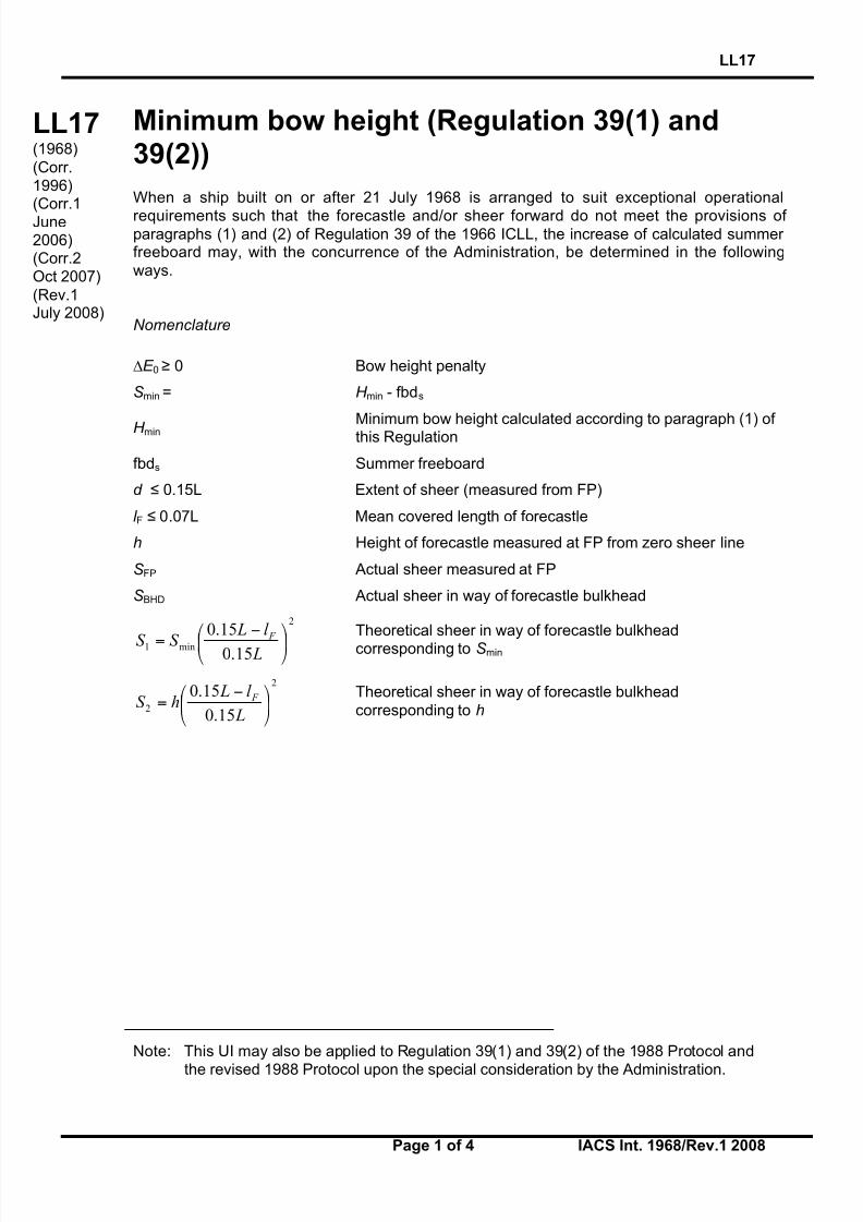
Minimum bow height (Regulation 39(1) and39(2))
When a ship built on or after 21 July 1968 is arranged to suit exceptional operational
requirements such that the forecastle and/or sheer forward do not meet the provisions of paragraphs (1) and (2) of Regulation 39 of the 1966 ICLL, the increase of calculated summer freeboard may, with the concurrence of the Administration, be determined in the following
ways.
Nomenclature
!E 0 " 0 Bow height penalty
S min = H min - fbds
H minMinimum bow height calculated according to paragraph (1) of this Regulation
fbds Summer freeboard
d # 0.15L Extent of sheer (measured from FP)
l F # 0.07L Mean covered length of forecastle
h Height of forecastle measured at FP from zero sheer line
S FP Actual sheer measured at FP
S BHD Actual sheer in way of forecastle bulkhead
2
min1
15.0
15.0
!"
#$%
& '=
L
l L
S S F
Theoretical sheer in way of forecastle bulkheadcorresponding to S min
2
2
15.0
15.0!"
#$%
& '=
L
l LhS
F Theoretical sheer in way of forecastle bulkhead
corresponding to h
Note: This UI may also be applied to Regulation 39(1) and 39(2) of the 1988 Protocol and
the revised 1988 Protocol upon the special consideration by the Administration.
LL17(1968)
(Corr.1996)(Corr.1June2006)(Corr.2Oct 2007)
(Rev.1July 2008)

8/12/2019 loadline interpretion
http://slidepdf.com/reader/full/loadline-interpretion 28/137
LL17(cont)
LL17
Page 2 of 4 IACS Int. 1968/Rev.1 2008
a) Where no forecastle is fitted and the sheer forward extends less than 0.15L from foreperpendicular (FP):
015.0
min0 !"=#
L
d S S E FP
0 ! S FP ! 1.5S min
(b) Where there is no sheer on the forward part of the freeboard deck, and the forecastlelength is less than 0.07L from FP:
007.0
min0 !"=#
L
l hS E
F
0 ! h ! 1.5S min
The height of the forecastle at the bulkhead position shall not be less than theordinate, at that point, of a parabolic sheer curve having an ordinate S min at the
Parabolic sheer line
Forecastle deck
l F
hBHD
S minH min
h
0.15L
0.07L
Deck
FP
Actual deck line
Parabolic sheer line Effective deck line
fbds0.15L
S min H min
S FP
d
FP

8/12/2019 loadline interpretion
http://slidepdf.com/reader/full/loadline-interpretion 29/137
LL17(cont)
LL17
Page 3 of 4 IACS Int. 1968/Rev.1 2008
forward perpendicular and extending aft for a distance of 0.15L from the forwardperpendicular.
(c) Where the sheer forward extends less than 0.15L and the length of forecastle is lessthan 0.07L from FP:
(i) S min ! h ! 1.5S min
0 ! S BHD ! 1.5S 1
015.0
107.0
1
1min
min0 !""
#
$%%&
'
(
((""
#
$%%&
'(=)
F
F BHD F
l L
l d
S
S
L
l
S
hS E
Conditions:
!!!
"
!!!
#
$
%%&
'(()
*
+
++
%%
&
'((
)
*+
F
F BHD
F
l L
l d
S
S
L
l
S
h
15.01
07.0
1
1
min
not to be taken negative (less than zero)
The height of the forecastle at bulkhead must satisfy the same conditions as insubparagraph (b) of this paragraph.
Actual deck line
Forecastle deck
l F
hBHD
0.07L
S minH min
h
FP
0.15L
Parabolic sheer line
S1
Effective deck line
SBHD
d

8/12/2019 loadline interpretion
http://slidepdf.com/reader/full/loadline-interpretion 30/137
LL17(cont)
LL17
Page 4 of 4 IACS Int. 1968/Rev.1 2008
(ii) h ! S min
0 ! S BHD ! 1.5S 2
( ) !!"
#
$$%
&
'
'
'!"
#
$%
&
'+'=( F
F BHD F
l L
l d
S
S
L
l hhS E
15.01
07.01
2min0
" 0
Conditions:
!!!
"
!!!
#
$
%%&
'(()
*
+
++
%&
'()
*+
F
F BHD
F
l L
l d
S
S
L
l
15.01
07.01
2
not to be taken negative (less than zero)
The height of the forecastle at the bulkhead position shall not be less than the
ordinate, at that point, or a parabolic sheer curve having an ordinate h at the forwardperpendicular and extending aft for a distance of 0.15L from the forward
perpendicular.
In general, this interpretation should be applied to existing ships only. However, to suitexceptional operational requirements, and upon the special consideration by the
Administration, the provision of this interpretation may also be applied to new ships.
End of Document
Parabolicsheer line
S 2
Actual deck line
FP
0.15L
S BHD
d
0.07L
Forecastle deck
l F
Effective deck line
hH
min
S min
hBHD

8/12/2019 loadline interpretion
http://slidepdf.com/reader/full/loadline-interpretion 31/137
LL18
Page 1 of 1 IACS Int. 1968/Rev.1 2008
LL
(cont)
Freeboard tables (Regulation 28)
(a) Type A ships
(i) Freeboards for Type A ships with lengths between 365 m and 400 m shall be determinedby the following formula:
f = 221 + 16,10L - 0,02L2
where f is the freeboard in mmL is the length as defined in Regulation 3(1).
(ii) Freeboards for Type A ships with lengths of 400 m and above shall be the constant
value, 3460 mm.
(b) Type B ships
(i) Freeboards for Type B ships with lengths between 365 m and 400 m shall be determinedby the following formula:
f = - 587 + 23L - 0,0188L2
where f is the freeboard in mm
L is the length as defined in Regulation 3(1).
(ii) Freeboards for Type B ships with lengths of 400 m and above shall be the constantvalue, 5605 mm.
Footnote: This UI is also applicable to Regulation 28 of the 1988 Protocol and the revised1988 Protocol.
LL18(1968)(Rev.1July 2008)
End of Document

8/12/2019 loadline interpretion
http://slidepdf.com/reader/full/loadline-interpretion 32/137
LL19
Page 1 of 1 IACS Int. 1972/Rev.1 2008
LL
(cont)
Form of certificates (Article 18)
It is recommended that the model form of certificates given in Annex III of the Load LineConvention should be strictly adhered to and any deviations from this pattern should beavoided.
Footnote: This UI is also applicable to Article 18 of the 1988 Protocol and the revised 1988Protocol.
LL19(1972)(Rev.1July 2008)
End of Document

8/12/2019 loadline interpretion
http://slidepdf.com/reader/full/loadline-interpretion 33/137
LL20
Page 1 of 1 IACS Int. 1972/Rev.1 2008
LL
(cont)
Hatch beams and cover stiffeners of variablecross section (Regulations 15(4), 15(5), 15(6),15(7) and 16)
To avoid stresses and deflections exceeding those given in the above Regulations alongconstruction elements of variable cross section, the required section modulus calculated asfor constriction elements of constant cross section is to be increased by a factor K expressedby:
4.07
8.02.31
+
!!
+=
" # K
where 0101 , W W ll == ! "
The value of factor K obtained by the formula is not to be less than unity.
l 1, l 0, W 1 and W 0 are indicated on the sketch below:
The moment of inertia is likewise to be increased by the factor C expressed by:
!
! "
32.0
181 3
+
#
+=C
where0101 , I I ll == ! "
The value factor of C obtained by the formula is not to be less than unity.
I 1 and I 0 are indicated on the sketch above.
The use of the above formulae is limited to the determination of the strength of hatch beamsand covers in which abrupt changes in the section of the face material do no occur along thelength of the beam or cover.
Footnote: This UI is also applicable to Regulations 15(4), 15(5), 15(6), 15(7) and 16 of the1988 Protocol.
l1
W 0 I 0
l0
I 1W 1
LL20(1972)(Rev.1July 2008)
End of Document

8/12/2019 loadline interpretion
http://slidepdf.com/reader/full/loadline-interpretion 34/137
LL21
Page 1 of 1 IACS Int. 1972/Rev.1 2008
LL
(cont)
Cargo ports or similar openings below theuppermost load line (Regulation 21(2))
It is recommended that cargo ports or similar openings may be accepted submerged providedthe safety of the ship is in no way impaired. It is considered that the fitting of a second door of equivalent strength and watertightness is one acceptable arrangement. In that case leakage
detection device should be provided in the compartment between the two doors. Further,drainage of this compartment to the bilges controlled by an easily accessible screw downvalve, should be arranged. The outer door should preferably open outwards.
Footnote: This UI is also applicable to Regulation 21(2) of the 1988 Protocol.
LL21(1972)(Rev.1July 2008)
End of Document

8/12/2019 loadline interpretion
http://slidepdf.com/reader/full/loadline-interpretion 35/137
LL22
Page 1 of 1 IACS Int. 1972/Rev.1 2008
LL
(cont)
Position of the inboard end of discharges whentimber freeboard is assigned (Regulation 22(1))
It is considered that the position of the inboard end of discharges should be related to thetimber summer load waterline when timber freeboard is assigned.
Footnotes:
1. This UI is also applicable to Regulation 22(1) of the 1988 Protocol.
2. This UI is also applicable to Regulation 22-1 of the revised 1988 Protocol.
LL22(1972)(Rev.1July 2008)
End of Document

8/12/2019 loadline interpretion
http://slidepdf.com/reader/full/loadline-interpretion 36/137
LL23
Page 1 of 1 IACS Int. 1972/Rev.1 2008
LL
(cont)
Freeing arrangement(Regulations 26(5), 27(7) and 36(1)(e))
1. Regulation 27(7): Freeing arrangements on ships having reduced B freeboardassigned and fitted with bulwarks on the freeboard deck
For Type B ships with freeboards reduced by not more than 60% of the difference between Band A tables there shall be freeing port area in the lower part of the bulwarks equal to at least25% of the total area of the bulkwarks. The upper edge of the sheer strake shall be kept aslow as possible.
2. Regulations 26(5) and 36(1)(e): Freeing arrangements for Type A ships and Type B
ships with trunks
It is considered that a freeing port area, in the lower part of the bulwarks, of 33% of the totalarea of the bulwarks provides the 'other effective freeing arrangements' mentioned in
Regulation 26(5), and may be considered equivalent to the 50% open rails in way of trunksrequired by Regulation 36(1)(e).
Footnotes:
1. This UI is also applicable to Regulations 26(5), 27(8) and 36(1)(e) of the 1988 Protocol.
2. Paragraph 1 of this UI is also applicable to Regulation 27(8) of the revised 1988 Protocol.
LL23(1972)(Rev.1July 2008)
End of Document

8/12/2019 loadline interpretion
http://slidepdf.com/reader/full/loadline-interpretion 37/137
LL24
Page 1 of 1 IACS Int. 1972/Rev.1 2008
LL
(cont)
Negative depth correction (Regulation 31(3))
When the height of a superstructure, raised quarterdeck or trunk is less than thecorresponding standard height, it is recommended that the calculated reduction be correctedin the ratio of the height of the actual superstructure, raised quarterdeck or trunk to theapplicable standard height as defined in Regulation 33.
Footnote: This UI is also applicable to Regulation 31(3) of the 1988 Protocol and the revised
1988 Protocol.
LL24(1972)(Rev.1July 2008)
End of Document

8/12/2019 loadline interpretion
http://slidepdf.com/reader/full/loadline-interpretion 38/137
LL25
Page 1 of 1 IACS Int. 1972/Rev.1 2008
LL
(cont)
Effective length of raised quarterdeck(Regulation 35(4))
It is recommended that the maximum effective length of 0.6L of a raised quarterdeck which isstipulated by Regulation 35(4), is to be measured from the after perpendicular even where apoop is fitted in conjunction with the raised quarterdeck.
Footnote: This UI is also applicable to Regulation 35(4) of the 1988 Protocol.
LL25(1972)(Rev.1July 2008)
End of Document

8/12/2019 loadline interpretion
http://slidepdf.com/reader/full/loadline-interpretion 39/137
LL26
Page 1 of 1 IACS Int. 1972/Rev.2 2008
LL
(cont)
Continuous hatchways as trunk (Regulation 36)
It is recommended that continuous hatchways may be treated as a trunk in the freeboardcomputation provided Regulation 36 is complied with in all respects.
The trunk deck stringer referred to in Regulation 36(1)(b) may be fitted outboard of the trunk
side bulkhead in association with the following:
(i) The stringer so formed is to provide a clear walkway of at least 450 mm in width on eachside of the ship.
(ii) The stringer is to be of solid plate efficiently supported and stiffened.(iii) The stringer is to be as high above the freeboard deck as practicable. In the freeboard
calculation, the trunk height is to be reduced by at least 600 mm or by the actual
difference between the top of the trunk and the stinger, whichever is greater.(iv) Hatch cover securing appliances are to be accessible from the stringer or walkway.
(v) The breadth of the trunk is to be measured between the trunk side bulkheads.(vi) Regulation 36 is to be complied with in all other respects.
Footnote: This UI is also applicable to Regulation 36 of the 1988 Protocol.
LL26(1972)Rev.11983)(Rev.2
July 2008)
End of Document

8/12/2019 loadline interpretion
http://slidepdf.com/reader/full/loadline-interpretion 40/137
LL27
Page 1 of 1 IACS Int. 1972/Rev.1 2008
LL
(cont)
Less than standard hatch coamings on trunksof less than standard height (Regulation 36(4))
In the case where the trunk height is less than standard and the trunk hatch coamings arealso of less than standard height, or omitted entirely, doubt may arise whether the trunkhatchways are located in position 1 or position 2 and, consequently, about the reduction to be
made in the actual trunk height. It is considered that in these cases the reduction from theactual height of trunk on account of insufficient hatch coaming height shall be taken as thedifference between 600 mm and the actual height of coaming, or 600 mm if no hatchcoamings are fitted. Reduction in the actual height of trunk shall not be required in cases
where only small hatches with less than standard height coamings are fitted in the trunk deckfor which dispensation from the requirement of standard coaming height may be given.
Footnote: This UI is applicable to Regulation 36(4) of the 1988 Protocol.
LL27(1972)(Rev.1July 2008)
End of Document

8/12/2019 loadline interpretion
http://slidepdf.com/reader/full/loadline-interpretion 41/137
LL28
Page 1 of 1 IACS Int. 1972/Rev.1 2008
LL
(cont)
Deduction for superstructures and trunks(Regulations 37 and 38(12))
For the purpose of applying the table ‘Percentage of Deduction for Type B ships’ inRegulation 37(2) it is considered that any detached superstructure abaft midship whose after bulkhead is located 0.05L or more forward of the after perpendicular may be treated as a
detached bridge.
A superstructure whose after bulkhead is located within 0.05L from the after perpendicular shall not qualify as a detached bridge.
Any excess in the height of such a superstructure, which does not extend to the after
perpendicular, cannot be regarded as contributing to the sheer allowance contemplated inRegulation 38(12).
Footnote: This UI is applicable to Regulations 37 and 38(12) of the 1988 Protocol.
LL28(1972)(Rev.1July 2008)
End of Document

8/12/2019 loadline interpretion
http://slidepdf.com/reader/full/loadline-interpretion 42/137
LL29
Page 1 of 2 IACS Req. 1972/Rev.2 2008
LL29(cont)
Sheer Credit for Superimposed Superstructures(Regulation 38(5), 38(7) and 38(12))
(a) Regulation 38(5): Superstructures superimposed on a complete superstructure.
In applying Regulation 38(5) (sheer on a complete superstructure ship) where there is an
enclosed poop or forecastle superimposed on a complete superstructure, sheer credit shallbe allowed for such a poop or forecastle, according to the method of Regulation 38(12) as
shown in Fig 1.Fig. 1
(b) Regulation 38(7): Superstructures superimposed on a forecastle or poop (i.e. a
stepped forecastle or poop).
In applying Regulation 38(7) and 38(12) where a poop or forecastle consists of two layers,the method shown in Fig 2 shall be used:
Fig. 2
Footnote: This UI is applicable to Regulations 38(5), 38(7) and 38(12) of the 1988 Protocol.
LL29(1972)
(Rev.11983)(Rev.2July 2008)

8/12/2019 loadline interpretion
http://slidepdf.com/reader/full/loadline-interpretion 43/137

8/12/2019 loadline interpretion
http://slidepdf.com/reader/full/loadline-interpretion 44/137
LL30
Page 1 of 1 IACS Req. 1972/Rev.1 2008
A2(cont)
Sheer allowance for excess height of superstructure (Regulations 38(7) and 38(12))
As Regulation 38(7) and (12) does not refer to a raised quarter deck it is recommended thatcredit under this paragraph be given for this type of superstructure only when the height of the raised quarterdeck is greater than the standard height of 'other superstructures' as
defined in Regulation 33, and only for the amount by which the actual height of the raisedquarterdeck exceeds that standard height.
Footnote: This UI is applicable to Regulations 38(7) and 38(12) of the 1988 Protocol.
LL30(1972)
(Rev.1July 2008)
End of
Document

8/12/2019 loadline interpretion
http://slidepdf.com/reader/full/loadline-interpretion 45/137

8/12/2019 loadline interpretion
http://slidepdf.com/reader/full/loadline-interpretion 46/137
LL32
Page 1 of 1 IACS Req. 1972
A2(cont)
Special requirements for vehicle ferries,ro-ro ships and other ships of similar type
Withdrawn Oct 2007, re-categorised as UI SC220 (NEW Oct 2007)
LL32(1972)
End of Document

8/12/2019 loadline interpretion
http://slidepdf.com/reader/full/loadline-interpretion 47/137
LL33
Page 1 of 1 IACS Int. 1972/Rev.1 2008
LL
(cont)
Timber freeboards for ships having reducedType B freeboards assigned (Regulations 45(2)and 45(3))
It is understood that some Administrations accept that timber freeboards may be assigned toships with reduced Type B freeboards, provided the timber freeboards are calculated on thebasis of the ordinary Type B freeboard.
It is recommended that Regulation 45(2) and (3) is interpreted or, if necessary, amended
such that the Timber Winter mark and/or the Timber Winter North Atlantic mark are placed atthe same level as the reduced Type B Winter mark when the computed Timber Winter markand/or the computed Timber Winter North Atlantic mark fall below the reduced Type B Winter mark.
Footnote: This UI is applicable to Regulations 45(2) and 45(3) of the 1988 Protocol.
LL33(1972)(Rev.1July 2008)
End of Document

8/12/2019 loadline interpretion
http://slidepdf.com/reader/full/loadline-interpretion 48/137
LL34
Page 1 of 1 IACS Int. 1972 / Corr.1 2008
LL
(cont)
Freeboard for lighters and barges (Regulation27(11) of 1966 ILLC)
In applying Regulation 27(11) to deck cargo barges it is recommended that only Type Bfreeboard can be assigned, even if the barges possess the same integrity of exposed decksand equivalent safety against flooding as normal tank barges.
This view is taken as a result of the consideration that Type A freeboard can only be assignedto liquid cargo barges.
It is further concluded that deck cargo can only be carried on barges to which Type Bfreeboard is assigned.
LL34(1972)(Corr.1July 2008)
End of Document

8/12/2019 loadline interpretion
http://slidepdf.com/reader/full/loadline-interpretion 49/137
LL35
Page 1 of 1 IACS Int. 1972/Corr.1 2008
LL
(cont)
Stowage of timber deck cargo on ships havingtimber freeboards assigned (Regulations 44and 45)
It is recommended that for the purpose of applying Regulation 45 the timber deck cargo shallextend as far outboard as possible due allowance being given for obstructions such as guardrails, stanchions, uprights, etc.
LL35(1972)(Corr.1July 2008)
End of Document
8/12/2019 loadline interpretion
http://slidepdf.com/reader/full/loadline-interpretion 50/137
LL36
Page 1 of 1 IACS Int. 1975/Rev.2 2008
LL
(cont)
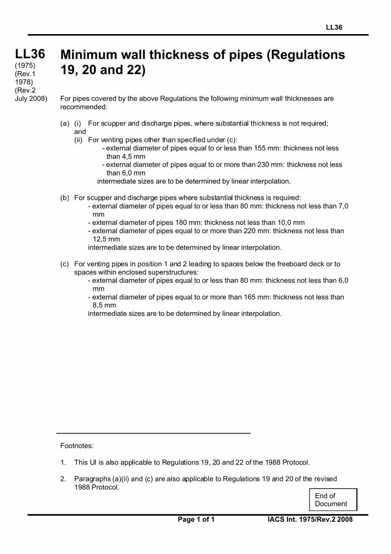
Minimum wall thickness of pipes (Regulations19, 20 and 22)
For pipes covered by the above Regulations the following minimum wall thicknesses arerecommended:
(a) (i) For scupper and discharge pipes, where substantial thickness is not required;and(ii) For venting pipes other than specified under (c):
- external diameter of pipes equal to or less than 155 mm: thickness not less
than 4,5 mm- external diameter of pipes equal to or more than 230 mm: thickness not less
than 6,0 mmintermediate sizes are to be determined by linear interpolation.
(b) For scupper and discharge pipes where substantial thickness is required:
- external diameter of pipes equal to or less than 80 mm: thickness not less than 7,0mm
- external diameter of pipes 180 mm: thickness not less than 10,0 mm- external diameter of pipes equal to or more than 220 mm: thickness not less than
12,5 mm
intermediate sizes are to be determined by linear interpolation.
(c) For venting pipes in position 1 and 2 leading to spaces below the freeboard deck or tospaces within enclosed superstructures:
- external diameter of pipes equal to or less than 80 mm: thickness not less than 6,0
mm- external diameter of pipes equal to or more than 165 mm: thickness not less than8,5 mm
intermediate sizes are to be determined by linear interpolation.
Footnotes:
1. This UI is also applicable to Regulations 19, 20 and 22 of the 1988 Protocol.
2. Paragraphs (a)(ii) and (c) are also applicable to Regulations 19 and 20 of the revised
1988 Protocol.
LL36(1975)(Rev.11978)(Rev.2
July 2008)
End of Document

8/12/2019 loadline interpretion
http://slidepdf.com/reader/full/loadline-interpretion 51/137
LL37
Page 1 of 2 IACS Int. 1975/Rev.2 2008
LL37(cont)
Superstructures with sloping end bulkheads(Regulations 34, 35 and 38(12))
When taking account of superstructures which have sloping end bulkheads in the calculationsof freeboards, such superstructures shall be dealt with in the following manner:
(a) Regulation 34
(i) When the height of the superstructure, clear of slope, is equal to or smaller than thestandard height, length S is to be obtained as shown in Fig. 1.
(ii) When the height is greater than the standard, length S is to be obtained as shown in Fig2.
(iii) The foregoing will apply only when the slope, related to the base line, is 15° or greater.Where the slope is less than 15°, the configuration will be treated as sheer.
(b) Regulation 35
When the height of the superstructure, clear of the slope, is less than the standard height, itseffective length E shall be its length S as obtained from (a)(i), reduced in the ratio of theactual height to the standard height.
Footnote: This UI is also applicable to Regulations 34, 35 and 38(12) of the 1988 Protocol.
LL37(1975)(Rev.11983)(Corr.
1996)(Rev.2July 2008)

8/12/2019 loadline interpretion
http://slidepdf.com/reader/full/loadline-interpretion 52/137
LL37
Page 2 of 2 IACS Int. 1975/Rev.2 2008
LL37(cont)
(c) Regulation 38(12)
When a poop or a forecastle has sloping end bulkheads, the sheer credit may be allowed on
account of excess height, the formula given in Regulation 38(12) shall be used, the values for y and L’ being as shown in Fig 3.
End of Document

8/12/2019 loadline interpretion
http://slidepdf.com/reader/full/loadline-interpretion 53/137
LL38
Page 1 of 2 IACS Int. 1976/Rev.2 2008
LL38(cont)
Bow Height (Regulation 39(2))
1. When calculating bow height, the sheer of the forecastle deck may be taken intoaccount, even if the length of the forecastle is less than 0.15L, but greater than 0.07L,provided that the forecastle height is not less than one half of standard height of superstructure as defined in Regulation 33 between 0.07L and the forward terminal.
2. Where the forecastle height is less than one half of standard height of superstructure,as defined in Regulation 33, the credited bow height may be determined as follows (Figs 1and 2 illustrate the intention of 2.1 and 2.2 respectively):
2.1 When the freeboard deck has sheer extending from abaft 0.15L, by a parabolic curvehaving its origin at 0.15L abaft the forward terminal at a height equal to the midship depth of
the ship, extended through the point of intersection of forecastle bulkhead and deck, and upto a point at the forward terminal not higher than the level of the forecastle deck. However, if
the value of the height denoted ht on Fig 1 is smaller than the value of the height denoted hb,then ht may be replaced in the available bow height.
2.2 When the freeboard deck has sheer extending for less than 0.15L or has no sheer, by
a line from the forecastle deck at side at 0.07L extended parallel to the base line to theforward terminal.
Fig.1
Footnote: This UI is applicable to Regulation 39(2) of the 1988 Protocol.
LL38(1976)(Rev.11983)(Corr.1
Jun 2006)(Rev.2July 2008)

8/12/2019 loadline interpretion
http://slidepdf.com/reader/full/loadline-interpretion 54/137
LL38
Page 2 of 2 IACS Int. 1976/Rev.2 2008
LL38(cont)
Fig. 2
hf = Half standard height of superstructure as defined in regulation 33.
t
b
bt Z x
LZ h !"
"#
$%%&
'=
2
15.0
End of Document

8/12/2019 loadline interpretion
http://slidepdf.com/reader/full/loadline-interpretion 55/137
LL39
Page 1 of 1 IACS Int. 1977/Rev.1 2008
LL
(cont)
Structure of a lower freeboard deck (Regulation3(9))
When a lower deck is designated as the freeboard deck, it shall be continuous in fore and aftdirection as well as athwartships. Such a freeboard deck as a minimum shall consist of suitable framed stringers at the ship sides and transversely at each watertight bulkhead which
extends to the upper deck, within cargo spaces. The width of these stringers shall not be lessthan can be conveniently fitted having regard to the structure and the operation of the ship.
Any arrangement of stringers shall be such that structural requirements can also be met.
NOTE
Member Societies formulated this Interpretation in order to have a guide when judging whether astructure below the uppermost complete deck can be designated as a freeboard deck in terms of
Regulation 3(9) for the application of tonnage regulations. This was done, although it is obvious thatsuch a structure has no significance with regard to the philosophy of the Load Line Convention.
Nevertheless it is felt that it would be preferable if tonnage and load line matters could be clearlyseparated by deleting from the Load Line Convention the reference to a lower deck being designatedas the freeboard deck.
Footnote: This UI is also applicable to to Regulation 3(9) of the 1988 Protocol.
LL39(1977)(Rev.1July 2008)
End of Document

8/12/2019 loadline interpretion
http://slidepdf.com/reader/full/loadline-interpretion 56/137
LL40
Page 1 of 1 IACS Int. 1977/Rev.2 2008
LL
(cont)
Security of hatch covers (Regulation 15(13))
Acceptable equivalent means to steel bars shall consist of devices and materials which willprovide strength equivalent to, and elasticity not greater than that of, steel.
Steel wire ropes cannot be regarded as satisfactory equivalent means.
Care is to be taken that tarpaulins are adequately protected from the possibility of damagearising from the use of securing devices which do not provide a flat bearing surface.
Footnotes:
1. This UI is also applicable to Regulation 15(13) of the 1988 Protocol.
2. This UI is also applicable to Regulation 15(12) of the revised 1988 Protocol.
LL40(1977)(Rev.11980)(Rev.2
July 2008)
End of Document
8/12/2019 loadline interpretion
http://slidepdf.com/reader/full/loadline-interpretion 57/137
LL41
Page 1 of 1 IACS Int. 1978/Rev.1 2008
LL
(cont)
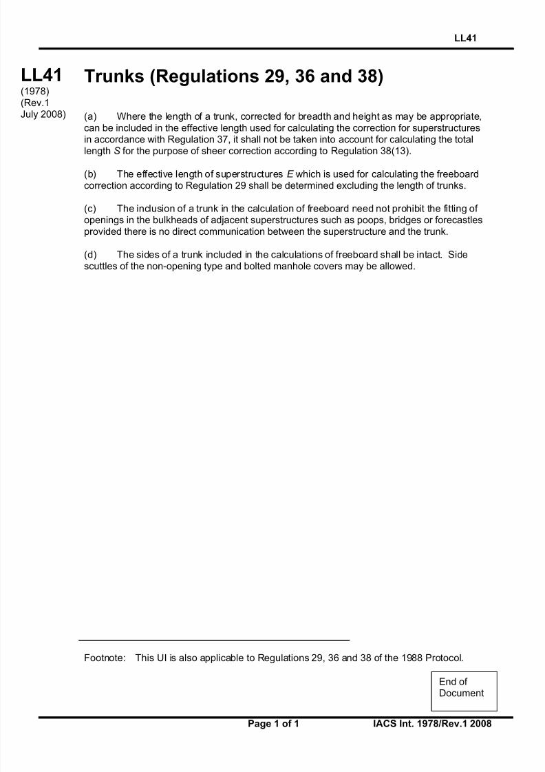
Trunks (Regulations 29, 36 and 38)
(a) Where the length of a trunk, corrected for breadth and height as may be appropriate,can be included in the effective length used for calculating the correction for superstructuresin accordance with Regulation 37, it shall not be taken into account for calculating the totallength S for the purpose of sheer correction according to Regulation 38(13).
(b) The effective length of superstructures E which is used for calculating the freeboardcorrection according to Regulation 29 shall be determined excluding the length of trunks.
(c) The inclusion of a trunk in the calculation of freeboard need not prohibit the fitting of openings in the bulkheads of adjacent superstructures such as poops, bridges or forecastlesprovided there is no direct communication between the superstructure and the trunk.
(d) The sides of a trunk included in the calculations of freeboard shall be intact. Side
scuttles of the non-opening type and bolted manhole covers may be allowed.
Footnote: This UI is also applicable to Regulations 29, 36 and 38 of the 1988 Protocol.
LL41(1978)(Rev.1July 2008)
End of Document

8/12/2019 loadline interpretion
http://slidepdf.com/reader/full/loadline-interpretion 58/137
LL42
Page 1 of 1 IACS Int. 1978/Rev.1 2008
LL
(cont)
Access openings on barges (Regulation 27(11))
(a) Since Regulation 27(11) does not contain any indication as to what size the term‘small access openings’ refers it is recommended that such openings should not be greater than 1,5 m2 where a freeboard reduction of 25% is granted.
(b) Access plates are considered as being equivalent to an intact deck for unmannedbarges, thereby allowing for a 25% reduction in freeboard, provided they are secured byclosely spaced bolts, their joining parts are properly gasketed and their arrangements, for allpractical purposes, have equivalent structural integrity and tightness as an intact deck.
Footnote: This UI is also applicable to Regulation 27(14)(c) of the 1988 Protocol and therevised 1988 Protocol.
LL42(1978)(Rev.1July 2008)
End of Document
8/12/2019 loadline interpretion
http://slidepdf.com/reader/full/loadline-interpretion 59/137
LL43
Page 1 of 1 IACS Int. 1978/Rev.1 2008
LL
(cont)
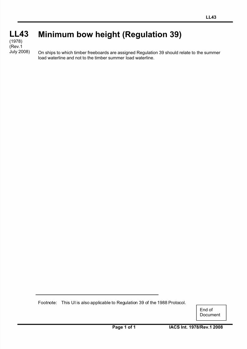
Minimum bow height (Regulation 39)
On ships to which timber freeboards are assigned Regulation 39 should relate to the summer load waterline and not to the timber summer load waterline.
Footnote: This UI is also applicable to Regulation 39 of the 1988 Protocol.
LL43(1978)(Rev.1July 2008)
End of Document

8/12/2019 loadline interpretion
http://slidepdf.com/reader/full/loadline-interpretion 60/137
LL44
Page 1 of 1 IACS Int. 1978/Rev.1 2008
LL
(cont)
Freeing ports (Regulation 24(3))
The effectiveness of the freeing area in bulwarks required by Regulation 24(1) and (2)depends on free flow across the deck of a ship. Where there is no free flow due to thepresence of a continuous trunk or hatchway coaming, the freeing area in bulwarks iscalculated in accordance with Regulation 24(3).
The free flow area on deck is the net area of gaps between hatchways, and betweenhatchways and superstructures and deck houses up to the actual height of the bulwark.
The freeing port area in bulwarks should be assessed in relation to the net flow area asfollows:
i. If the free flow area is not less that the freeing area calculated from Regulation 24(3) as if the hatchway coamings were continuous, then the minimum freeing port area calculated
from Regulation 24(1) and (2) should be deemed sufficient.
ii. If the free flow area is equal to, or less than the area calculated from Regulations 24(1)and (2), then the minimum freeing area in the bulwarks should be determined from
Regulation 24(3).
iii. If the free flow area is smaller than that calculated from Regulation 24(3), but greater than that calculated from Regulation 24(1) and (2), the minimum freeing area in the
bulwark should be determined from the following formula:
F = F 1 + F 2 – f p (m2)
where F 1 is the minimum freeing area calculated from Regulations 24(1) and (2),F 2 is the minimum freeing area calculated from Regulation 24(3),f p is the total net area of passages and gaps between hatch ends and
superstructures or deckhouses up to the actual height of bulwark.
Footnote: This UI is also applicable to Regulation 24(3) of the 1988 Protocol.
LL44(1978)(Rev.1July 2008)
End of Document

8/12/2019 loadline interpretion
http://slidepdf.com/reader/full/loadline-interpretion 61/137
LL45
Page 1 of 1 IACS Int. 1978/Rev.2 2008
LL45(cont)
Presentation of stability data (Regulation 10(2))
Regulation 10(2) of 1966 Convention and 1988 Protocol requires that:
"The master of every new ship which is not already provided with stability information under an international convention for the safety of life at sea in force shall be supplied with sufficient information in an approved form to give him guidance as to the stability of the ship under
varying conditions of service, and a copy shall be furnished to the Administration."
Regulation 10(2) of the revised 1988 Protocol requires that:
“Information shall be provided to the master in a form that is approved by the Administrationor a recognised organization. Stability information, and loading information also related toship strength when required under paragraph (1), shall be carried on board at all times
together with evidence that the information has been approved by the Administration.”
Interpretation
To ensure that ships are provided with meaningful information which accords with the senseof Regulation 10(2) a document containing such information is to be prepared on the basis of
MSC Circular 920.
Additionally full details of the stability criteria appropriate to the ship under all anticipatedconditions of service shall be clearly stated in text supplemented as necessary by diagrams
using the nomenclature adopted in the document.
Where requirements for wind and/or wave forces and ice accretion are specified by theadministration full details are to be given.
Footnotes:
1. Rev.2 of this Unified Interpretation is to be applied by all Members and Associates onship with a contract for construction on or after 1 September 2008.
2. The “contracted for construction” date means the date on which the contract to build the
vessel is signed between the prospective owner and the shipbuilder. For further detailsregarding the date of “contract for construction”, refer to IACS Procedural Requirement
(PR) No. 29.
LL45(1978)(Rev.11984)(Rev.2
Aug 2008)
End of Document

8/12/2019 loadline interpretion
http://slidepdf.com/reader/full/loadline-interpretion 62/137
LL46
Page 1 of 1 IACS Int. 1979/Rev.3 2008
LL
(cont)
Protection of openings in raised quarterdecks(Regulation 18(2) and Interpretation LL8)
Regarding the requirement to protect openings in superstructures (Regulation 18(2)) it isconsidered that openings in the top of a deckhouse on a raised quarterdeck, or on the deck of a superstructure or on the deck of a deckhouse of less than standard height, having a height
equal to or greater than the standard quarterdeck height are to be provided with anacceptable means of closing but need not be protected by an efficient deckhouse or companionway as defined in the regulation provided the height of the deckhouse is at leastthe height of superstructure.
Footnote: This UI is also applicable to Regulation 18(2) of the 1988 Protocol.
LL46(1979)(Rev.11980)(Rev.2
1997)(Rev.3July 2008)
End of Document

8/12/2019 loadline interpretion
http://slidepdf.com/reader/full/loadline-interpretion 63/137
LL47
Page 1 of 2 IACS Int. 1979/Rev.3 2008
LL47(cont’d)
Guard Rails
Content
A. Guard Rails (Regulation 25(2) and (3) of 1966 ICLL and the 1988 Protocol)
B. Guard Rails (Regulation 25(3)(b) of the 1988 Protocol to the ICLL 1966 as amended byresolution MSC.143(77))
****A. Guard Rails (Regulation 25(2) and (3) of 1966 ICLL and the 1988 Protocol)
Regulation 25(2) and (3) of 1966 ICLL read:
(2) Efficient guard rails or bulwarks shall be fitted to all exposed parts of the freeboard andsuperstructure decks. The height of the bulwarks or guard rails shall be at least 1 m (39_
inches) from the deck, provided that where this height would interfere with the normal operationof the ship, a lesser height may be approved if the Administration is satisfied that adequateprotection is provided.
(3) The opening below the lowest course of the guard rails shall not exceed 230 mm (9inches). The other courses shall be not more than 380 mm (15 inches) apart. In the case of ships with rounded gunwales the guard rail supports shall be placed on the flat of the deck.
Interpretation
(a) Fixed, removable or hinged stanchions shall be fitted about 1,5 m apart.
(b) At least every third stanchion shall be supported by a bracket or stay. In lieu of this, flat
steel stanchions shall be of increased breadth as given in Figure 1, and aligned withmember below deck unless the deck plating thickness exceeds 20 mm.
(c) Wire ropes may only be accepted in lieu of guard rails in special circumstances and
then only in limited lengths.
(d) Lengths of chain may only be accepted in lieu of guard rails if they are fitted betweentwo fixed stanchions and/or bulwarks.
(e) The openings between courses should be in accordance with Regulation 25(3) of the
Convention.
Note:
1. Rev.2 was withdrawn in Nov 2006, to remove ambiguity in referencing relevant regulations.
2. Rev.2.1 of this UI is to be uniformly applied by IACS Societies to ships contracted for construction on or after 1 April 2007. However, Societies are not precluded from applying this UIbefore such date.
3. The “contracted for construction” date means the date on which the contract to build the vesselis signed between the prospective owner and the shipbuilder. For further details regarding the
date of “contract for construction”, refer to IACS Procedural Requirement (PR) No. 29.
LL47(1979)(Rev.11980)(Rev.2
June2006)(Rev.2.1
Oct 2006)(Corr.1
Oct 2007)(Rev.3
July 2008)

8/12/2019 loadline interpretion
http://slidepdf.com/reader/full/loadline-interpretion 64/137
LL47
Page 2 of 2 IACS Int. 1979/Rev.3 2008
LL47(cont’d)
(f) Wires shall be made taut by means of turnbuckles.
(g) Removable or hinged stanchions shall be capable of being locked in the uprightposition.
****
B. Guard Rails (Regulation 25(3)(b) of the 1988 Protocol to the ICLL 1966 as amended by resolution MSC.143(77))
Regulation 25(3)(b) of the 1988 Protocol to the ICLL 1966 as amended by resolutionMSC.143(77) reads:
(b) At least every third stanchion shall be supported by a bracket or stay.
Interpretation
As alternate arrangements (required by Regulation 25(3)(b)), flat steel stanchions shall be of
increased breadth as given in Figure 1, and aligned with member below deck unless the deckplating thickness exceeds 20 mm.
In lieu of at least every third stanchion supported bystay, alternatively:
(a) at least every third stanchion shall be of
increased breadth: k!bs = 2.9!bs
(b) at least every second stanchion shall be of
increased breadth: k!bs = 2.4!bs
(c) Every stanchion shall be of increased breadth:k!bs = 1.9!bs
where
bs breadth of normal stanchion according to thedesign standard
o
o
500 (Min.)
bs
kbs
Stanchions with increased breadth to be aligned with member belowdeck, min. 100x12 flatbar welded to deck by double continuous filletweld. The stanchions with increased breadth need not be alignedwith under deck structure for deck plating exceeding 20 mm.
Fig. 1 Guardrail stanchion of increased breadth, welded to deck with double continuousfillet weld with leg size of min. 7 mm or as specified by the design standard.
End of
Document
8/12/2019 loadline interpretion
http://slidepdf.com/reader/full/loadline-interpretion 65/137
LL48
Page 1 of 2 IACS Int. 1980/Rev.2 2008
LL48(cont)
Moulded Depth (Regulation 3(5)(c) and 3(9) andFreeboard Calculation (Regulation 40(1))
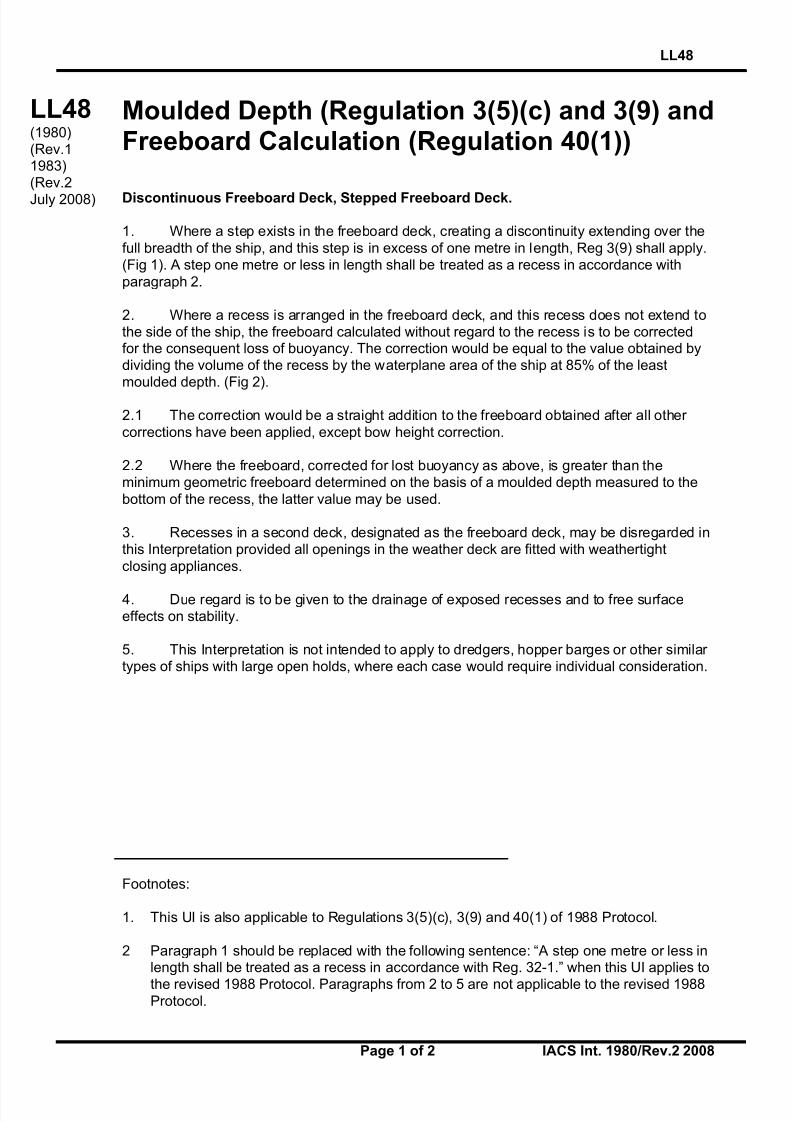
Discontinuous Freeboard Deck, Stepped Freeboard Deck.
1. Where a step exists in the freeboard deck, creating a discontinuity extending over the
full breadth of the ship, and this step is in excess of one metre in length, Reg 3(9) shall apply.(Fig 1). A step one metre or less in length shall be treated as a recess in accordance with
paragraph 2.
2. Where a recess is arranged in the freeboard deck, and this recess does not extend tothe side of the ship, the freeboard calculated without regard to the recess is to be correctedfor the consequent loss of buoyancy. The correction would be equal to the value obtained bydividing the volume of the recess by the waterplane area of the ship at 85% of the leastmoulded depth. (Fig 2).
2.1 The correction would be a straight addition to the freeboard obtained after all other
corrections have been applied, except bow height correction.
2.2 Where the freeboard, corrected for lost buoyancy as above, is greater than theminimum geometric freeboard determined on the basis of a moulded depth measured to the
bottom of the recess, the latter value may be used.
3. Recesses in a second deck, designated as the freeboard deck, may be disregarded inthis Interpretation provided all openings in the weather deck are fitted with weathertight
closing appliances.
4. Due regard is to be given to the drainage of exposed recesses and to free surfaceeffects on stability.
5. This Interpretation is not intended to apply to dredgers, hopper barges or other similar types of ships with large open holds, where each case would require individual consideration.
Footnotes:
1. This UI is also applicable to Regulations 3(5)(c), 3(9) and 40(1) of 1988 Protocol.
2 Paragraph 1 should be replaced with the following sentence: “A step one metre or less inlength shall be treated as a recess in accordance with Reg. 32-1.” when this UI applies to
the revised 1988 Protocol. Paragraphs from 2 to 5 are not applicable to the revised 1988Protocol.
LL48(1980)(Rev.11983)(Rev.2
July 2008)

8/12/2019 loadline interpretion
http://slidepdf.com/reader/full/loadline-interpretion 66/137
LL48
Page 2 of 2 IACS Int. 1980/Rev.2 2008
LL48(cont)
Fig. 1 (Para. 1)
Fig. 2 (Para. 2)
Correction is addition to freeboard equal to:
End of Document
8/12/2019 loadline interpretion
http://slidepdf.com/reader/full/loadline-interpretion 67/137
LL49
Page 1 of 1 IACS Int. 1980/Rev.1 2008
LL
(cont)
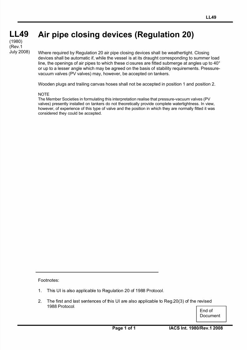
Air pipe closing devices (Regulation 20)
Where required by Regulation 20 air pipe closing devices shall be weathertight. Closingdevices shall be automatic if, while the vessel is at its draught corresponding to summer loadline, the openings of air pipes to which these closures are fitted submerge at angles up to 40°or up to a lesser angle which may be agreed on the basis of stability requirements. Pressure-
vacuum valves (PV valves) may, however, be accepted on tankers.
Wooden plugs and trailing canvas hoses shall not be accepted in position 1 and position 2.
NOTEThe Member Societies in formulating this interpretation realise that pressure-vacuum valves (PVvalves) presently installed on tankers do not theoretically provide complete watertightness. In view,however, of experience of this type of valve and the position in which they are normally fitted it wasconsidered they could be accepted.
Footnotes:
1. This UI is also applicable to Regulation 20 of 1988 Protocol.
2. The first and last sentences of this UI are also applicable to Reg.20(3) of the revised
1988 Protocol.
LL49(1980)(Rev.1July 2008)
End of Document

8/12/2019 loadline interpretion
http://slidepdf.com/reader/full/loadline-interpretion 68/137
LL50
Page 1 of 3 IACS Int. 1982/Rev.5 2008
LL50(cont)
Protection of Crew(Load Line Convention Regulation 25(4), 26(2)and 27(7) and SOLAS II-1/3-3)
When applying Regulation 25(4), 26(2) and 27(7) of the ICLL 1966, as well as Regulation II-1/3-3 of SOLAS the protection of crew should be provided at least one of the means denotedin the table given below:
Acceptable arrangements accordingto type of freeboard assigned:Type of
ShipLocations of access in Ship
AssignedSummer
Freeboard Type ATypeB-100
TypeB-60
TypeB&B+
! 3000 mm ab
e
ab
e
ab
c(1)
ef(1)
1.1. Access to Midship Quarters
1.1.1. Between poop and bridge, or
1.1.2. Between poop and deckhousecontaining living accommodationor navigating equipment, or both.
> 3000 mm abe
abe
abc(1)c(2)
ef(1)f(2)
! 3000 mm abc(1)ef(1)
abc(1)c(2)e
f(1)f(2)
abc(1)c(2)e
f(1)f(2)
All Shipsother than
OilTankers*,ChemicalTankers*
and GasCarriers*
1.2 Access to Ends
1.2.1. Between poop and bow( if thereis no bridge),
1.2.2. Between bridge and bow, or
1.2.3. Between a deckhousecontaining living accommodationor navigating equipment, or both, and bow, or
1.2.4. In the case of a flush deck
vessel, between crewaccommodation and the forwardand after ends of ship.
> 3000 mm abc(1)d(1)e
f(1)
abc(1)c(2)d(1)
d(2)ef(1)f(2)
abc(1)c(2)c(4)
d(1)d(2)d(3)ef(1)f(2)f(4)
ab
c(1)
c(2)c(4)d(1)d(2)d(3)ef(1)
f(2)f(4)
Footnotes:
1. This UI will be applied by all Members and Associates for ships that are subject to the
referenced ICLL and SOLAS Regulations.
2. This UI is also applicable to Regulations 25(4), 26(2) and 27(8) of 1988 Protocol.
LL50(1982)(Rev. 11986)(Rev. 2
1997)(Rev. 31998)
(Rev. 4.1October
1998)(Rev. 5
July 2008)

8/12/2019 loadline interpretion
http://slidepdf.com/reader/full/loadline-interpretion 69/137
LL50
Page 2 of 3 IACS Int. 1982/Rev.5 2008
LL50(cont)
! (Af + Hs)**
a
ef(1)f(5)
2.1 Access to Bow
2.1.1. Between poop and bow, or
2.1.2. Between a deckhousecontaining living accommodationor navigating equipment, or both, and bow, or
2.1.3. In the case of a flush deck
vessel, between crewaccommodation and the forwardends of ship.
> (Af + Hs)**
aef(1)f(2)
Oil
Tankers*,ChemicalTankers*and GasCarriers*
2.2 Access to After End
In the case of a flush deckvessel, between crew
accommodation and the after end of ship
as required in 1.2.4 for other types of ships
* Oil Tankers, Chemical Tanker and Gas Carrier as defined in SOLAS II-1/2.12, VII/8.2 and VII/11.2respectively
** Af : the minimum summer freeboard calculated as type A ship regardless of the type freeboard actuallyassigned.Hs: the standard height of superstructure as defined in ICLL Regulation 33.
Note: Deviations from some or all of these requirements or alternative arrangements for such cases as ships with
very high gangways (i.e. certain gas carriers) may be allowed subject to agreement case-by-case with the relevantflag Administration.
For oil tanker, as defined in SOLAS II-1/2.12, chemical tankers as defined in SOLAS VII/8.2
or gas carriers as defined in SOLAS VII/11.2, constructed before 1st July 1998, existing
arrangements which complied with (b) or (c) may be accepted in lieu of (e) or (f) providedsuch existing arrangements are fitted with shelters and means of access to and from the deckas required for the arrangements (e) or (f) as defined below.
For tankers less than 100 m in length, the minimum width of the gangway platform or decklevel walkway fitted in accordance with arrangement (e) or (f), respectively, may be reducedto 0.6 m.
Acceptable arrangements referred to in the table are defined as follows:
(a) A well lighted and ventilated under-deck passageway (clear opening 0.8 m wide, 2.0m high) as close as practicable to the freeboard deck, connecting and providing access to the
locations in question.
(b) A permanent and efficiently constructed gangway fitted at or above the level of thesuperstructure deck on or as near as practicable to the centre line of the ship, providing a
continuous platform at least 0.6 m in width and a non-slip surface, with guard rails extendingon each side throughout its length. Guard rails shall be at least 1 m high with courses as
required in Load Line Regulation 25(3), and supported by stanchions spaced not more than1.5 m; a foot-stop shall be provided.
(c) A permanent walkway at least 0.6 m in width fitted at freeboard deck level consistingof two rows of guard rails with stanchions spaced not more than 3 m. The number of coursesof rails and their spacing are to be as required by Regulation 25(3). On Type B ships,
hatchway coamings not less than 0.6 m in height may be regarded as forming one side of thewalkway, provided that between the hatchways two rows of guard rails are fitted.

8/12/2019 loadline interpretion
http://slidepdf.com/reader/full/loadline-interpretion 70/137
8/12/2019 loadline interpretion
http://slidepdf.com/reader/full/loadline-interpretion 71/137
LL51
Page 1 of 1 IACS Int. 1983/Rev.2 2008
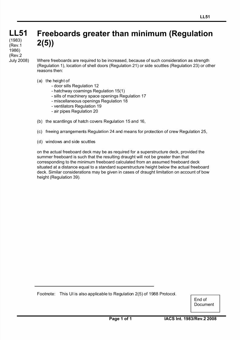
LL
(cont)
Freeboards greater than minimum (Regulation2(5))
Where freeboards are required to be increased, because of such consideration as strength(Regulation 1), location of shell doors (Regulation 21) or side scuttles (Regulation 23) or other reasons then:
(a) the height of - door sills Regulation 12- hatchway coamings Regulation 15(1)
- sills of machinery space openings Regulation 17- miscellaneous openings Regulation 18
- ventilators Regulation 19- air pipes Regulation 20
(b) the scantlings of hatch covers Regulation 15 and 16,
(c) freeing arrangements Regulation 24 and means for protection of crew Regulation 25,
(d) windows and side scuttles
on the actual freeboard deck may be as required for a superstructure deck, provided thesummer freeboard is such that the resulting draught will not be greater than that
corresponding to the minimum freeboard calculated from an assumed freeboard decksituated at a distance equal to a standard superstructure height below the actual freeboarddeck. Similar considerations may be given in cases of draught limitation on account of bow
height (Regulation 39).
Footnote: This UI is also applicable to Regulation 2(5) of 1988 Protocol.
LL51(1983)(Rev.11986)(Rev.2
July 2008)
End of Document

8/12/2019 loadline interpretion
http://slidepdf.com/reader/full/loadline-interpretion 72/137
LL52
Page 1 of 1 IACS Int. 1983/Rev.1 2008
LL
(cont)
Weathertight closing appliances for ventilators(Regulation 19(4))
Where required by Regulation 19, weathertight closing appliances for all ventilators inpositions 1 and 2 are to be of steel or other equivalent materials.
Wood plugs and canvas covers are not acceptable in these positions.
Footnote: This UI is also applicable to Regulation 19(4) of 1988 Protocol.
LL52(1983)(Rev.1July 2008)
End of Document
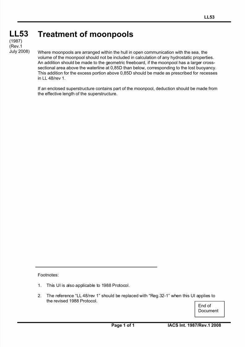
8/12/2019 loadline interpretion
http://slidepdf.com/reader/full/loadline-interpretion 73/137
LL53
Page 1 of 1 IACS Int. 1987/Rev.1 2008
LL
(cont)
Treatment of moonpools
Where moonpools are arranged within the hull in open communication with the sea, thevolume of the moonpool should not be included in calculation of any hydrostatic properties.
An addition should be made to the geometric freeboard, if the moonpool has a larger cross-sectional area above the waterline at 0,85D than below, corresponding to the lost buoyancy.
This addition for the excess portion above 0,85D should be made as prescribed for recessesin LL 48/rev 1.
If an enclosed superstructure contains part of the moonpool, deduction should be made fromthe effective length of the superstructure.
Footnotes:
1. This UI is also applicable to 1988 Protocol.
2. The reference “LL 48/rev 1” should be replaced with “Reg.32-1” when this UI applies tothe revised 1988 Protocol.
LL53(1987)(Rev.1July 2008)
End of Document

8/12/2019 loadline interpretion
http://slidepdf.com/reader/full/loadline-interpretion 74/137
LL54
Page 1 of 1 IACS Int. 1989/Rev.1 2008
LL
(cont)
Effective length of superstructures (Regulation35(3))
When calculating the freeboard for a ship with excessive sheer but without any superstructureat 0,2L amidships, the deduction for sheer per Regulation 38(15) is not to be granted.However, where a poop or forecastle of less than standard height is fitted, when applying
Regulation 35(3), credit may be given to the height of the poop or forecastle by increasing itby the difference between the actual and the standard sheer profiles.
When the height of the superstructure, clear of the slope, is less than the standard height, its
effective length E shall be its length S as obtained from (a)(i), reduced in the ratio of theactual height to the standard height.
Footnote: This UI is also applicable to Regulation 35(3) of the 1988 Protocol.
LL54(1989)(Rev.1July 2008)
End of Document

8/12/2019 loadline interpretion
http://slidepdf.com/reader/full/loadline-interpretion 75/137

8/12/2019 loadline interpretion
http://slidepdf.com/reader/full/loadline-interpretion 76/137
LL56
Page 1 of 1 IACS Int. 1993/Rev.1 2008
LL
(cont)
Block Coefficient of a Pontoon (Regulation 3(7))
When calculating the block coefficient of a pontoon, according to the definition of Regulation3(7), the 96%-length, if applicable, shall be used disregarding the fact that this might lead to acoefficient greater than 1,0.
Footnote: This UI is also applicable to Regulation 3(7) of the 1988 Protocol.
LL56(1993)(Rev.1July 2008)
End of Document

8/12/2019 loadline interpretion
http://slidepdf.com/reader/full/loadline-interpretion 77/137
LL57
Page 1 of 1 IACS Int. 1996/Rev.1 2008
LL
(cont)
Block Coefficient of a Multi-hull Craft(Regulation 3(7))
When calculating the block coefficient (Cb) of a multi-hull craft according to the definition of Regulation 3(7), the full breadth (B) as defined in regulation 3(4) is to be used and not thebreadth of a single hull.
Footnote: This UI is also applicable to Regulation 3(7) of the 1988 Protocol.
LL57(1996)(Rev.1July 2008)
End of Document
8/12/2019 loadline interpretion
http://slidepdf.com/reader/full/loadline-interpretion 78/137
LL58
Page 1 of 1 IACS Int. 1997/Rev.1 2008
LL
(cont)
Machinery space and emergency generator room ventilator coaming heights(Regulations 17(2), 19(3) and 19(4))
Regulation 17(2) requires that the coamings of machinery space ventilators situated inexposed positions on the freeboard and superstructure decks be as high above the deck as isreasonable and practicable.
In general, ventilators necessary to continuously supply the machinery space and, on
demand, immediately supply the emergency generator room should have coamings whichcomply with regulation 19(3), without having to fit weathertight closing appliances.
However, where due to vessel size and arrangement this is not practicable, lesser heights for machinery space and emergency generator room ventilator coamings may be accepted with
provision of weathertight closing appliances in accordance with regulation 19(4) incombination with other suitable arrangements to ensure an uninterrupted, adequate supply of
ventilation to these spaces.
Footnote: This UI is also applicable to Regulations 17(2), 19(3) and 19(4) of the 1988
Protocol.
LL58(1997)(Rev.1July 2008)
End of Document

8/12/2019 loadline interpretion
http://slidepdf.com/reader/full/loadline-interpretion 79/137
LL59
Page 1 of 3 IACS Int. 1997/Rev.1 2007
LL59(cont)
Cargo manifold gutter bars - freeingarrangements and intact stability
(ICLL Regulation 24(1)(g) and Regulation 26)
ICLL 1988, as amended by res. MSC.143(77), Regulation 24 Freeing Ports
(1)(g) Gutter bars greater than 300 mm in height fitted around the weather decks of tankersin way of cargo manifolds and cargo piping shall be treated as bulwarks. Freeing ports
shall be arranged in accordance with this regulation. Closures attached to the freeingports for use during loading and discharge operations are to be arranged in such a
way that jamming cannot occur while at sea.
ICLL 1966, Regulation 26 Special Conditions of Assignment for Type "A" Ships
Machinery Casings
(1) Machinery casings on Type "A" ships as defined in Regulation 27 shall be protected by an
enclosed poop or bridge of at least standard height, or by a deckhouse of equal height andequivalent strength, provided that machinery casings may be exposed if there are noopenings giving direct access from the freeboard deck to the machinery space. A door complying with the requirements of Regulation 12 may, however, be permitted in the
machinery casing, provided that it leads to a space or passageway which is as stronglyconstructed as the casing and is separated from the stairway to the engine room by a second
weathertight door of steel or other equivalent material.
Gangway and Access
(2) An efficiently constructed fore and aft permanent gangway of sufficient strength shall befitted on Type "A" ships at the level of the superstructure deck between the poop and themidship bridge or deckhouse where fitted, or equivalent means of access shall be provided tocarry out the purpose of the gangway, such as passages below deck. Elsewhere, and onType "A" ships without a midship bridge, arrangements to the satisfaction of the
Administration shall be provided to safeguard the crew in reaching all parts used in thenecessary work of the ship.
(3) Safe and satisfactory access from the gangway level shall be available between separatecrew accommodations and also between crew accommodations and the machinery space.
Hatchways
(4) Exposed hatchways on the freeboard and forecastle decks or on the tops of expansiontrunks on Type "A" ships shall be provided with efficient watertight covers of steel or other equivalent material.
Note:
1. Rev.1 of this Unified Interpretation is to be uniformly implemented by all Members and Associates from 1 July 2008, unless otherwise instructed by a Flag State.
LL59(1997)(Rev.1Dec 2007)

8/12/2019 loadline interpretion
http://slidepdf.com/reader/full/loadline-interpretion 80/137
LL59
Page 2 of 3 IACS Int. 1997/Rev.1 2007
LL59(cont)
Freeing Arrangements
(5) Type "A" ships with bulwarks shall have open rails fitted for at least half the length of theexposed parts of the weather deck or other effective freeing arrangements. The upper edge
of the sheer strake shall be kept as low as practicable.
(6) Where superstructures are connected by trunks, open rails shall be fitted for the wholelength of the exposed parts of the freeboard deck.
ICLL 1988, Regulation 26 Special conditions of assignment for type 'A' ships
Machinery casings
(1) Machinery casings on type 'A' ships, as defined in regulation 27, shall be protected by
one of the following arrangements:
(a) an enclosed poop or bridge of at least standard height; or
(b) a deckhouse of equal height and equivalent strength.
(2) Machinery casings may, however, be exposed if there are no openings giving direct
access from the freeboard deck to the machinery space. A door complying with therequirements of regulation 12 is acceptable in the machinery casing, provided that it
leads to a space or passageway which is as strongly constructed as the casing and isseparated from the stairway to the engine-room by a second weathertight door of
steel or other equivalent material.
Gangway and access
(3) A fore-and-aft permanent gangway, constructed in accordance with the provisions of regulation 25-1(2)(e), shall be fitted on type 'A' ships at the level of the superstructure
deck between the poop and the midship bridge or deckhouse where fitted. Thearrangement contained in regulation 25-1(2)(a) is considered an equivalent means of access to carry out the purpose of the gangway.
(4) Safe access from the gangway level shall be available between separate crewaccommodations and also between crew accommodations and the machinery space.
Hatchways
(5) Exposed hatchways on the freeboard and forecastle decks or on the tops of
expansion trunks on type 'A' ships shall be provided with efficient watertight covers of steel or other equivalent material.
Freeing arrangements
(6) Type 'A' ships with bulwarks shall have open rails fitted for at least half the length of the weather deck or other equivalent freeing arrangements. A freeing port area, in thelower part of the bulwarks, of 33% of the total area of the bulwarks, is an acceptableequivalent freeing arrangement. The upper edge of the sheer strake shall be kept as
low as practicable.
(7) Where superstructures are connected by trunks, open rails shall be fitted for the wholelength of the exposed parts of the freeboard deck.

8/12/2019 loadline interpretion
http://slidepdf.com/reader/full/loadline-interpretion 81/137
LL59
Page 3 of 3 IACS Int. 1997/Rev.1 2007
LL59(cont)
Interpretation
Where gutter bars are installed on the weather decks of tankers in way of cargo manifoldsand are extended aft as far as the after house front for the purpose of containing cargo spills
on deck during loading and discharge operations, the free surface effects caused bycontainment of a cargo spill during liquid transfer operations or of boarding seas whileunderway require consideration with respect to the vessel’s available margin of positive initialstability (GMo).
Where the gutter bars installed are greater than 300 mm in height, they are to be treated as
bulwarks according to the Load Line Convention with freeing ports arranged in accordancewith Regulation 24 and effective closures provided for use during loading and dischargeoperations. Attached closures are to be arranged in such a way that jamming cannot occur while at sea, ensuring that the freeing ports will remain fully effective.
On ships without deck camber, or where the height of the installed gutter bars exceeds thecamber, and for tankers having cargo tanks exceeding 60% of the vessel’s maximum beam
at midships regardless of gutter bar height, gutter bars should not be accepted without anassessment of the initial stability (GMo) for compliance with the relevant intact stabilityrequirement taking into account the free surface effect caused by liquids contained by thegutter bars.
End of Document

8/12/2019 loadline interpretion
http://slidepdf.com/reader/full/loadline-interpretion 82/137
LL60
Page 1 of 2 IACS Int. 1997/Rev.1 2008
LL60(cont)
Freeing ports in way of wells in combinationwith open superstructures(Regulation 24(1) and 24(4))
In the case of vessels having open superstructures on the freeboard or superstructure decks,which open to wells formed by bulwarks on the peripheries of the open decks, the conventionleaves to the satisfaction of the Administration how the freeing port areas for the open spaceswithin the superstructures are to be calculated.
Since water can enter only through the end bulkhead openings, the freeing port areas for the
open spaces within the superstructures should be a function of the breadth of the endopenings and the extent to which wells formed by the open decks and common spaces within
the open superstructures are covered by the open superstructures.
To determine the minimum freeing port area on each side of the ship for the opensuperstructure (AS) and for the open well (AW), the following procedure is recommended:
1. Determine the total well length (lt) equal to the sum of the length of the open deckenclosed by bulwarks (lW) and the length of the common space within the opensuperstructure (lS).
2. To determine (AS):
2.1 Calculate the freeing port area (A) required for an open well of length lt in accordancewith regulation 24(1) with standard height bulwark assumed.
2.2 Multiply by the factor of 1.5 to correct for the absence of sheer, if applicable, in
accordance with regulation 24(2).
2.3 Multiply by the factor (bO/lt) to adjust the freeing port area for the breadth (bO) of theopenings in the end bulkhead of the enclosed superstructure. (Note: this cancels the ltterms from the calculation.)
2.4 To adjust the freeing port area for that part of the entire length of the well which isenclosed by the open superstructure, multiply by the factor:
1-(lW/lt)2
where lW and lt are defined in 1 above.
2.5 To adjust the freeing port area for the distance of the well deck above the freeboarddeck, multiply by the factor:
0.5 (hS/hW )
where hW is the distance of the well deck above the freeboard deck and hs is onestandard superstructure height.
Footnote: This UI is also applicable to Regulation 24(1) and 24(4) of the 1988 Protocol.
LL60(1997)(Corr.1April1998)
(Rev.1July 2008)

8/12/2019 loadline interpretion
http://slidepdf.com/reader/full/loadline-interpretion 83/137
LL60
Page 2 of 2 IACS Int. 1997/Rev.1 2008
LL60(cont)
3. To determine (AW):
3.1 The freeing port area for the open well (AW) is to be calculated in accordance with step
2.1 above, using lW to calculate (A’), and then adjusted for the actual height of thebulwark (hb) by the application of one of the following area corrections, whichever isapplicable:
For bulwarks greater than 1.2 m in height:
AC = lW ((hb-1.2)/(0.10)) (0.004) m2
For bulwarks less than 0.9 m in height:
AC = lW ((hb-0.9)/(0.10)) (0.004) m2
For bulwarks between 1.2 m and 0.9 m in height:
AC = 0.00 m2
3.2 The corrected freeing port area, (AW = A’ + AC), is then adjusted for absence of sheer, if
applicable, and height above freeboard deck as in steps 2.2 and 2.5 above, using hS andhW.
4. The resulting freeing port areas for the open superstructure (AS) and for the open well
(AW) are to be provided along each side of the open space covered by the opensuperstructure and each side of the open well respectively.
5. The above relationships are summarised by the following equations, assuming lt, the sum
of lW and lS , is greater than 20 m*:
Freeing port area AW for the open well:
AW = (0.07 lW+ AC) (sheer correction) (0.5hS/hW)
Freeing port area AS for the open superstructure:
AS = (0.07lt) (sheer correction) (bO/lt) (1 - (lW/lt)2) (0.5hS/hW)
* Where lt is 20 m or less, the basic freeing port area is A = 0.7 + 0.035lt in accordance
with Regulation 24(1). Units are to be consistent with those in the Convention.
End of
Document

8/12/2019 loadline interpretion
http://slidepdf.com/reader/full/loadline-interpretion 84/137
LL61
Page 1 of 3 IACS Int. 1997/Rev.1 2008
LL61(cont)
Method of correction for the effect of freesurface of liquids in tanks (Regulation 10(2), URL3 and UI LL45)
1 For all loading conditions, the initial metacentric height and the righting lever curveshould be corrected for the effect of free surfaces of liquids in tanks.
2 Free surface effects will exist whenever the filling level in a tank is less than 100% and
greater than 0%. Where the total free surface effects of nominally full (i.e. 98% or above)tanks is small in relation to the metacentric height of the vessel, with the agreement of the
administration the effects for such tanks may be ignored. Free surface effects should beconsidered whenever the filling level in a tank is less than 98%.
3 Tanks which are taken into consideration when determining the free surfacecorrection may be in one of two categories:
3.1 Tanks with filling levels fixed (e.g. liquid cargo, water ballast). The free surface
correction should be determined for the actual filling level to be used in each tank.
3.2 Tanks with filling levels variable (e.g. consumable liquids such as fuel oil, diesel oil,and fresh water, and also liquid cargo and water ballast during liquid transfer operations).
Except as permitted in 5 and 6, the free surface correction should be the maximum valueattainable between the filling limits envisaged for each tank, consistent with any operatinginstructions.
4 In calculating the free surface effects in tanks containing consumable liquids, it shouldbe assumed that for each type of liquid at least one transverse pair or a single centreline tankhas a free surface and the tank or combination of tanks taken into account should be those
where the effect of free surfaces is the greatest.
5 Where water ballast tanks, including anti-rolling tanks and anti-heeling tanks, are to befilled or discharged during the course of a voyage, the free surface effects should be
calculated to take account of the most onerous transitory stage relating to such operations.
6 For vessels engaged in liquid transfer operations, the free surface corrections at anystage of the liquid transfer operations may be determined in accordance with the filling levelin each tank at that stage of the transfer operation.
7 The corrections to the initial metacentric height and to the righting lever curve shouldbe addressed separately as follows:
7.1 In determining the correction to initial metacentric height, the transverse moments of inertia of the tanks should be calculated at 0 degrees angle of heel according to thecategories indicated in 3.
Footnote: This UI is also applicable to Regulation 10(2) of the 1988 Protocol and the revised1988 Protocol.
LL61(1997)(Rev.1July 2008)

8/12/2019 loadline interpretion
http://slidepdf.com/reader/full/loadline-interpretion 85/137
LL61
Page 2 of 3 IACS Int. 1997/Rev.1 2008
LL61(cont)
7.2 The righting lever curve may be corrected by any of the following methods subject tothe agreement of the Administration:
.1 Correction based on the actual moment of fluid transfer for each angle of heelcalculated.
.2 Correction based on the moment of inertia, calculated at 0 degrees angle of heel,
modified at each angle of heel calculated, (i.e.: GG1sin!).
.3 Correction based on the summation of Mfs values for all tanks taken intoconsideration, see 8.
With the exception of item 7.2.3 above, corrections may be calculated according to the
categories indicated in 3.
Whichever method is selected for correcting the righting lever curve, only that method should
be presented in the vessel's stability booklet. However, where an alternative method isdescribed for use in manually calculating loading conditions, an explanation of the differenceswhich may be found in the results, as well as an example correction for each alternative,
should be included.
8 The values of Mfs for each tank may be derived from the formula:
! " k vbM fs =
where:
Mfs is the free surface moment at any inclination in metre-tonnesv is the tank total capacity in cubic metres
b is the tank maximum breadth in metres
" is the mass density of liquid in the tank in tonnes/cubic metre
# is equal to v/blh (the tank block coefficient)
h is the tank maximum height in metresl is the tank maximum length in metresk is the dimensionless coefficient to be determined from the following table according to
the ratio b/h. The intermediate values are determined by interpolation.
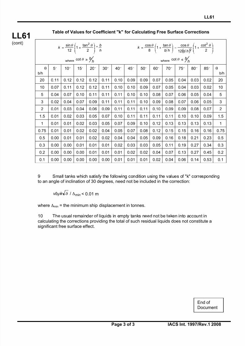
8/12/2019 loadline interpretion
http://slidepdf.com/reader/full/loadline-interpretion 86/137
LL61
Page 3 of 3 IACS Int. 1997/Rev.1 2008
LL61(cont)
Table of Values for Coefficient "k" for Calculating Free Surface Corrections
h
bk *
2
tan1
12
sin 2
!!
"
#
$$
%
&+=
' '
( ) !!
"
#
$$
%
&+'!!
"
#$$%
&+=
2
cot1
12
costan1
8
cos 2
2
( ( ( (
hbhbk
where h
b!" cot
where h
b!" cot
!b/h
5° 10° 15° 20° 30° 40° 45° 50° 60° 70° 75° 80° 85° !b/h
20 0.11 0.12 0.12 0.12 0.11 0.10 0.09 0.09 0.07 0.05 0.04 0.03 0.02 20
10 0.07 0.11 0.12 0.12 0.11 0.10 0.10 0.09 0.07 0.05 0.04 0.03 0.02 10
5 0.04 0.07 0.10 0.11 0.11 0.11 0.10 0.10 0.08 0.07 0.06 0.05 0.04 5
3 0.02 0.04 0.07 0.09 0.11 0.11 0.11 0.10 0.09 0.08 0.07 0.06 0.05 3
2 0.01 0.03 0.04 0.06 0.09 0.11 0.11 0.11 0.10 0.09 0.09 0.08 0.07 2
1.5 0.01 0.02 0.03 0.05 0.07 0.10 0.11 0.11 0.11 0.11 0.10 0.10 0.09 1.5
1 0.01 0.01 0.02 0.03 0.05 0.07 0.09 0.10 0.12 0.13 0.13 0.13 0.13 1
0.75 0.01 0.01 0.02 0.02 0.04 0.05 0.07 0.08 0.12 0.15 0.15 0.16 0.16 0.75
0.5 0.00 0.01 0.01 0.02 0.02 0.04 0.04 0.05 0.09 0.16 0.18 0.21 0.23 0.5
0.3 0.00 0.00 0.01 0.01 0.01 0.02 0.03 0.03 0.05 0.11 0.19 0.27 0.34 0.3
0.2 0.00 0.00 0.00 0.01 0.01 0.01 0.02 0.02 0.04 0.07 0.13 0.27 0.45 0.2
0.1 0.00 0.00 0.00 0.00 0.00 0.01 0.01 0.01 0.02 0.04 0.06 0.14 0.53 0.1
9 Small tanks which satisfy the following condition using the values of "k" corresponding
to an angle of inclination of 30 degrees, need not be included in the correction:
min/ !" # k vb < 0.01 m
where $min = the minimum ship displacement in tonnes.
10 The usual remainder of liquids in empty tanks need not be taken into account in
calculating the corrections providing the total of such residual liquids does not constitute asignificant free surface effect.
End of Document

8/12/2019 loadline interpretion
http://slidepdf.com/reader/full/loadline-interpretion 87/137
LL62
Page 1 of 2 IACS Int. 1997/Rev.1 2008
LL62(cont)
Side Scuttles, Windows and Skylights(Regulation 23)
(1) Side scuttles and windows together with their glasses, deadlights1 and storm covers, if
fitted, shall be of approved design and substantial construction in accordance with, orequivalent to, recognised national or international standards. Non-metallic frames are notacceptable.
(2) Side scuttles are defined as being round, or oval, openings with an area notexceeding 0.16 square metres. Round or oval openings having areas exceeding 0.16 squaremetres shall be treated as windows.
(3) Windows are defined as being rectangular openings generally, having a radius ateach corner relative to the window size in accordance with recognised national orinternational standards, and round, or oval, openings with an area exceeding 0.16 squaremetres.
(4) Side scuttles to the following spaces shall be fitted with efficient hinged insidedeadlights:
(a) spaces below freeboard deck(b) spaces within the first tier of enclosed superstructures(c) first tier deckhouses on the freeboard deck protecting openings leading below or
considered buoyant in stability calculations.
The deadlights shall be capable of being effectively closed and secured watertight if fittedbelow freeboard deck and weathertight if fitted above.
(5) Side scuttles shall not be fitted in such a position that their sills are below a line drawnparallel to the freeboard deck at side and having its lowest point 2.5 percent of the breadth B,or 500 mm, whichever is the greatest distance, above the summer load line (or timbersummer load line if assigned).
(6) Side scuttles shall be of the non-opening type in ships subject to damage stabilityregulations, if calculations indicate that they would become immersed by any intermediatestage of flooding or the final equilibrium waterplane in any required damage case.
(7) Windows shall not be fitted below the freeboard deck, in the first tier end bulkheads orsides of enclosed superstructures and in first tier deckhouses2 considered buoyant in the
stability calculations or protecting openings leading below. _____________________________1 ‘Deadlights’, in accordance with recognised standards, are fitted to the inside of windows and side scuttles
while ‘storm covers’, of comparable specifications to deadlights, are fitted to the outside of windows, whereaccessible, and may be hinged or portable. 2 Two members reserved their position for those cases where this first tier is not considered buoyant, provided
efficient deadlights are fitted.
Footnotes:
1. This UI is also applicable to Regulation 23 of the 1988 Protocol.
2. Paragraph 7 of this UI is applicable to Reg. 23(7)(c) of the revised 1988 Protocol.
3. Paragraph 11 of this UI is applicable to Reg. 23(11) of the revised 1988 Protocol.
LL62(1997)(Rev.1July 2008)(Corr.1
Aug 2010)
IACS Int. 1997/Corr.1 2010
8/12/2019 loadline interpretion
http://slidepdf.com/reader/full/loadline-interpretion 88/137

8/12/2019 loadline interpretion
http://slidepdf.com/reader/full/loadline-interpretion 89/137
LL63
Page 1 of 3 IACS Int. 1998/Rev.2 2008
LL63(cont)
Treatment of steps and recesses in transversesubdivision bulkheads: IMO Res. A.320 (IX),paragraphs 12(d) and 12(e), and Regulation
27(12)(d) and (e), Revised 1988 ICLL (MSC.143(77))
Regulation 27, paragraphs 12(d) of 1988 ICLL as amended by Res. MSC.143(77) reads:“Except where otherwise required by paragraph (10)(a), the flooding shall be confined to asingle compartment between adjacent transverse bulkheads, provided that the inner
longitudinal boundary of the compartment is not in a position within the transverse extent of assumed damage. Transverse boundary bulkheads of wing tanks, which do not extend over the full breadth of the ship shall be assumed not to be damaged, provided that they extend beyond the transverse extent of assumed damage prescribed in subparagraph (b). If in a
transverse bulkhead there are steps or recesses of not more than 3 m in length, located within the transverse extent of assumed damage as defined in subparagraph (b), such
transverse bulkhead may be considered intact and the adjacent compartment may befloodable singly. If, however, within the transverse extent of assumed damage there is a stepor recess of more than 3 m in length in a transverse bulkhead, the two compartmentsadjacent to this bulkhead shall be considered as flooded. The step formed by the afterpeak bulkhead and the afterpeak tank top shall not be regarded as a step for the purpose of this
regulation.”
Regulation 27, paragraphs 12(e) of 1988 ICLL as amended by Res. MSC.143(77) reads:“Where a main transverse bulkhead is located within the transverse extent of assumed damage and is stepped in way of a double bottom or side tank by more than 3 m, the doublebottom or side tanks adjacent to the stepped portion of the main transverse bulkhead shall be
considered as flooded simultaneously. If this side tank has openings into one or several holds, such as grain feeding holes, such hold or holds shall be considered as flooded simultaneously. Similarly, in a ship designed for the carriage of fluid cargoes, if a side tank has openings into adjacent compartments, such adjacent compartments shall be considered
as empty and as being flooded simultaneously. This provision is applicable even where suchopenings are fitted with closing appliances, except in the case of sluice valves fitted in
bulkheads between tanks and where the valves are controlled from the deck. Manhole coverswith closely spaced bolts are considered equivalent to the unpierced bulkhead, except in thecase of openings in topside tanks making the topside tanks common to the holds.”
Notes:
1. This UI shall be uniformly implemented by all IACS Members and Associates to shipscontracted for construction after 1 January 1999.
2. The “contracted for construction” date means the date on which the contract to build the
vessel is signed between the prospective owner and the shipbuilder. For further detailsregarding the date of “contract for construction”, refer to IACS Procedural Requirement(PR) No. 29.
3. Longitudinal distance of 3.0(m) referred in sub-item (a) and figures 1 to 4 should bereplaced with 3.05(m), when this interpretation applies to Res. A.320.
Footnote: This UI is also applicable to Regulation 27(12)(d) and (e) of the 1988 Protocol.
LL63(July1998)(Rev.1July 2004)
(Rev.2July 2008)

8/12/2019 loadline interpretion
http://slidepdf.com/reader/full/loadline-interpretion 90/137
LL63
Page 2 of 3 IACS Int. 1998/Rev.2 2008
LL63(cont) Interpretation
Where a transverse bulkhead forming the forward or aft limit of a wing tank or double bottomtank is not in line with the main transverse bulkhead of the adjacent in board compartment, itis considered to form a step or recess in the main transverse bulkhead.
Such a step or recess should be assumed not to be damaged provided that, either:
(a) the longitudinal extent of the step or recess, measured from the plane of the maintransverse bulkhead, is not more than 3.0 metres, or:
(b) any longitudinal surface forming the step or recess is located inboard of the assumed
damage.
Where, otherwise, the transverse and longitudinal bulkheads bounding a main inboard
compartment are entirely in board of the assumed damage position, damage is assumed tooccur between the transverse bulkheads of the adjacent wing compartment. Any step or recess in such wing tank shall be treated as indicated above.
Representative examples to clarify treatment of steps within the
transverse extent of damage

8/12/2019 loadline interpretion
http://slidepdf.com/reader/full/loadline-interpretion 91/137
LL63
Page 3 of 3 IACS Int. 1998/Rev.2 2008
LL63(cont)
End of Document

8/12/2019 loadline interpretion
http://slidepdf.com/reader/full/loadline-interpretion 92/137
LL64
Page 1 of 2 IACS Int. 1998/Rev.5 2008
LL64(cont)
Non-weathertight hatch covers abovesuperstructure deck(Load Line Convention 1966 Regulations 2(5)
and 14(2))
The requirements for coaming height and weathertightness of hatch covers located above thesuperstructure deck are left to the satisfaction of the flag Administration by Regulations 2(5)and 14(2) of the Load Line Convention. Exposed coamings and hatch covers situated above
the second tier of the superstructure, or equivalent, or above the third tier, or equivalent, inthe forward quarter of the ship's length, may be regarded to be above the superstructure deckin the application of 14(2). Non-weathertight covers in these locations may be acceptedsubject to the approval of the flag Administration and conditional upon the following:
1. Their acceptance should be limited to use on container ships.
2. They may be fitted to hatchways located on weatherdecks which are at least twostandard superstructure heights above an actual freeboard deck or an assumed freeboarddeck from which a freeboard can be calculated which will result in a draught not less than thatcorresponding to the freeboard actually assigned. Where any part of a hatchway is forward of
a point located one quarter of the ship's length (0.25L) from the forward perpendicular, thathatchway is to be located on a weatherdeck at least three standard superstructure heights
above the actual or assumed freeboard deck. It is to be noted that the assumed freeboarddeck is used only for the purpose of measuring the height of the deck on which thehatchways are situated and may be an imaginary, or virtual deck and in this case is not to beused for the actual assignment of freeboard. The vessels freeboard is to be assigned from an
actual deck, designated as the freeboard deck, which is to be determined in accordance withthe Convention and LL39.
3. The hatchway coamings should be not less than 600 mm in height.
4. The non-weathertight gaps between hatch cover panels should be considered as
unprotected openings with respect to the requirements of intact and damage stabilitycalculations. They should be as small as possible commensurate with the capacity of thebilge system and expected water ingress, and the capacity and operational effectiveness of the fire-fighting system and, generally, should not exceed 50 mm.
Notes:
1. This Unified Interpretation is to be uniformly implemented by all Members and Associatesfrom 1 July 1999, unless otherwise instructed by a Flag State.
2. Changes introduced in Rev.3 are to be uniformly implemented by IACS Members and Associates from 1 January 2002.
3. Changes introduced in Rev.4 are to be uniformly implemented by IACS Members and Associate from 1 January 2006.
Footnote: This UI is also applicable to
Regulations 2(5) and 14(2) of the 1988 Protocol andthe revised 1988 Protocol.
LL64(December 1998)(Rev.1,March
1999)(Rev.2June 2000)
(Rev.3 July2001)
(Rev.4 July2005)
(Rev.5 July2008)

8/12/2019 loadline interpretion
http://slidepdf.com/reader/full/loadline-interpretion 93/137
LL64
Page 2 of 2 IACS Int. 1998/Rev.5 2008
LL64(cont)
5. Labyrinths, gutter bars, or equivalents should be fitted proximate to the edges of eachpanel in way of the gaps to minimise the amount of water that can enter the container holdfrom the top surface of each panel.
6. Scantlings of the hatch cover panels are to be equivalent to those for weathertightcovers and in accordance with the applicable requirements of UR S21 and UI LL70. Thedetails on the securing arrangements to the vessel’s support structure and coamings are
provided in IACS Recommendation No. 14.
7. Bilge alarms should be provided in each hold fitted with non-weathertight covers.
End of Document

8/12/2019 loadline interpretion
http://slidepdf.com/reader/full/loadline-interpretion 94/137
LL65
Page 1 of 1 IACS Int. 2000/Rev.2 2008
LL65(cont)
Ships with assigned or reassigned reducedfreeboards and intended to carry deck cargo
(SOLAS, Chapter II-1, Regulation 4, footnotes .6 and .7)
“Cargo ships shown to comply with the following regulations may be excluded from theapplication of part B-1:
.6 Damage stability requirements of regulation 27 of the 1966 Load Lines Convention as
applied in compliance with resolutions A.320(IX) and A.514(13), provided that in the case of cargo ships to which regulation 27(9) applies, main transverse watertight bulkheads, to be
considered effective, are spaced according to paragraph (12)(f) of resolution A.320(IX),except ships intended for the carriage of deck cargo; and
.7 Damage stability requirements of regulation 27 of the 1988 Load Lines Protocol, except ships intended for the carriage of deck cargo”.
General:
1. This UI pertains to ships intended to carry deck cargo and assigned or reassignedreduced freeboards in accordance with Regulation 27 of the International Conventionon Load Lines, 1966 (ICLL 1966) or the ICLL 1966 as amended by the 1988 Protocol.
2. In .6 and .7 of the footnotes to SOLAS Chapter II-1, Regulation 4, ships shown to
comply with ICLL 1966 Regulation 27 as applied in compliance with IMO Res. A.320and A.514, may be excluded from the application of SOLAS Chapter II-1 Part B-1,except if they carry deck cargo.
3. Therefore ships identified in item 1), above, shall:
a) according to the assigned reduced freeboards, comply with damage stabilityrequirements of Regulation 27 of ICLL 1966 and the 1988 Protocol to the ICLL1966; and
b) according to the intended deck cargo capacity, be provided with the limiting
GM or KG curve required by SOLAS Chapter II-1, Regulation 5-1.4 incompliance with the probabilistic damage stability analysis of SOLAS Chapter
II-1 Part B-1.
4. The KG used for demonstrating compliance with the criteria in 3 a) shall be the sameas that used for the criteria in 3 b) at the deepest subdivision load line.
Notes:
1. This UI LL 65 is to be uniformly implemented by IACS Members and Associatesfrom 1 July 2001.
2. Revision 1 is to be uniformly implemented by IACS Members and Associates from1 January 2009.
Footnote: This UI is also applicable to the revised 1988 Protocol.
LL65(June2000)(Rev.1June
2007)(Rev.2July 2008)
End of Document

8/12/2019 loadline interpretion
http://slidepdf.com/reader/full/loadline-interpretion 95/137
Hatch Cover Stress/Deflection Calculation(Res. MSC.143(77), 2005 LL Protocol Regulation 16(5) (a) & (b))
Regulation 16 Hatchways closed by weathertight covers of steel or otherequivalent materials
Hatch cover minimum design loads
(5) All hatch covers shall be designed such that:
(a) the product of the maximum stress determined in accordance with theabove loads and the factor of 1.25 does not exceed the minimum upperyield point strength of the material in tension and the critical bucklingstrength in compression;
(b) the deflection is limited to not more than 0.0056 times the span,
Interpretation
In the calculation of stress and deflection from the prescribed mass per unit area, the
design pressure is to be determined by using a vertical acceleration equal to 1.0g.
Note: This UI LL 66 is to be uniformly implemented by IACS Members and Associates from 1 January 2005.
LL66(Oct2003)
LL66
IACS Interpretations 2003
66-1

8/12/2019 loadline interpretion
http://slidepdf.com/reader/full/loadline-interpretion 96/137
Endorsement of Certificates with the Dateof Completion of the Survey on which they
are Based
“Resolutions MSC.170(79), MSC.171(79), MSC.172(79), MSC.174(79) throughMSC.179(79) and MSC.181(79) through MSC.187(79) require that the identifiedcertificates include the statement:
"Completion date of the survey on which this certificate is based:dd/mm/yyyy".
Interpretation
For application of the above resolutions, the following IACS UnifiedInterpretation applies:
The “Completion date of the survey on which this certificate is based”, is the date of the last initial/renewal survey visit on which all statutory and class items, required tobe surveyed, have been surveyed (regardless if they were found satisfactory or withminor deficiency).
Note:
1. This UI is to be uniformly implemented by IACS Members and Associates from 1March 2004.
2. Revision 1 of this UI is to be uniformly implemented by IACS Members and Associates from 1 July 2006.
SC183(Nov 2003)(Rev.1, Nov.2005)
LL67(Nov 2003)(Rev.1, Nov.2005)
MPC10(Nov 2003)(Rev.1, Nov.2005)
LL67
IACS Interpretations 2003/Rev.1 200567-1
▼ ▼

8/12/2019 loadline interpretion
http://slidepdf.com/reader/full/loadline-interpretion 97/137
LL68
Page 1 of 1 IACS Int. 2004/Rev.1 2008
LL
(cont)
Position of Freeboard Deck on Float On/FloatOff Barge Carriers(Regulation 3(9))
Reg.3(9):“Freeboard Deck . The freeboard deck is normally the uppermost complete deck exposed to
weather and sea, which has permanent means of closing all openings in the weather partthereof, and below which all openings in the sides of the ship are fitted with permanentmeans of watertight closing. In a ship having a discontinuous freeboard deck, the lowest lineof the exposed deck and the continuation of that line parallel to the upper part of the deck istaken as the freeboard deck. At the option of the owner and subject to the approval of the
Administration, a lower deck may be designated as the freeboard deck provided it is acomplete and permanent deck continuous in fore and aft direction at least between the
machinery space and peak bulkheads and continuous athwartships. When this lower deck isstepped the lowest line of the deck and the continuation of that line parallel to the upper part
of the deck is taken as the freeboard deck. When a lower deck is designated as the freeboarddeck, that part of the hull which extends above the freeboard deck is treated as a
superstructure so far as concerns the application of the conditions of assignment and thecalculation of freeboard. It is from this deck that the freeboard is calculated.”
Interpretation:
1. Float On/Float Off Barge Carriers are designed to be ballasted such that the bottom of
their cargo space(s) (well deck) submerges below the waterline to allow barges beingfloated in and out.
2. If such a ship is fitted with weathertight closures for the cargo space(s) and a
watertight enclosure at the stern, the uppermost complete deck may be taken as thefreeboard deck.
3. If such a ship is not fitted with weathertight closures for the cargo space(s) or awatertight enclosure at the stern, the well deck shall be taken as the freeboard deck,
while buoyant spaces above may be considered as superstructures in accordancewith UI LL 15 or 88 Prot. Reg. 34(1).
4. If such a ship is not fitted with weathertight closures for the cargo space(s) but has a
watertight enclosure at the stern, the uppermost complete deck may be taken as thefreeboard deck provided that:
- the structure of the freeboard deck complies with the requirements of LL39;- the calculated freeboard is corrected for any missing buoyancy above the well
deck in accordance with LL48, and
- a satisfactory safety level at the resulting draught is demonstrated according toalternative concepts.
Note: This UI is to be uniformly implemented by IACS Members and Associates from 1 April2005.
Footnote: This UI is also applicable to to Regulation 3(9) of the 1988 Protocol and the
revised 1988 Protocol.
LL68(May2004)(Rev.1July 2008)
End of Document

8/12/2019 loadline interpretion
http://slidepdf.com/reader/full/loadline-interpretion 98/137
LL69
Page 1 of 2 IACS Int. 2004/Rev.1 2008
LL69 (cont)
Interpretation to 1966 ICLL Reg. 27
Reg.27 of ICLL 1966: IMO Res. A.320 paragraph 12:
“Damage Assumptions
(12) The following principles regarding the character of the assumed damage apply:
(a) The vertical extent of damage in all cases is assumed to be from the base line upwardswithout limit.
(b) The transverse extent of damage is equal to B/5 or 11.5 metres (37.7 feet), which ever isthe lesser, measured inboard from the side of the ship perpendicularly to the centre lineat the level of the summer load water line.
(c) If damage of a lesser extent than specified in sub paragraphs (a) and (b) of this
paragraph results in a more severe condition, such lesser extent shall be assumed.
(d) Except where otherwise required by paragraph (10)(a) the flooding shall be confined to asingle compartment between adjacent transverse bulkheads provided the inner
longitudinal boundary of the compartment is not in a position within the transverse extentof assumed damage. Transverse boundary bulkheads of wing tanks, which do not extendover the full breadth of the ship shall be assumed not to be damaged, provided theyextend beyond the transverse extent of assumed damage prescribed in sub paragraph
(b) of this paragraph.
If in a transverse bulkhead there are steps or recesses of not more than 3.05 metres (10feet) in length located within the transverse extent of assumed damage as defined in
sub-paragraph (b) of this paragraph, such transverse bulkhead may be considered intactand the adjacent compartment may be floodable singly. If, however, within the transverseextent of assumed damage there is a step or recess of more than 3.05 metres (10 feet)
in length in a transverse bulkhead, the two compartments adjacent to this bulkhead shallbe considered as flooded. The step formed by the after peak bulkhead and the after peak
tank top shall not be regarded as a step for the purpose of this Regulation.
Notes:
1. This UI is to be uniformly implemented by IACS Members and Associates from 1 April2005.
2. The distance of 3.05 m referred in this UI should be replaced with 3.00 m, when this
interpretation applies to the 1988 Protocol and the revised 1988 Protocol.
LL69(May2004)(Rev.1July 2008)
8/12/2019 loadline interpretion
http://slidepdf.com/reader/full/loadline-interpretion 99/137
LL69
Page 2 of 2 IACS Int. 2004/Rev.1 2008
LL69 (cont)
(e) Where a main transverse bulkhead is located within the transverse extent of assumeddamage and is stepped in way of a double bottom or side tank by more than 3.05 metres(10 feet), the double bottom or side tanks adjacent to the stepped portion of the main
transverse bulkhead shall be considered as flooded simultaneously. If this side tank hasopenings into one or several holds, such as grain feeding holes, such hold or holds shallbe considered as flooded simultaneously. Similarly in a ship designed for the carriage of fluid cargoes, if a side tank has openings into adjacent compartments, such adjacent
compartments shall be considered as empty and flooded simultaneously. This provisionis applicable even where such openings are fitted with closing appliances, except in the
case of sluice valves fitted in bulkheads between tanks and where the valves arecontrolled from the deck. Manhole covers with closely spaced belts are consideredequivalent to the unpierced bulkhead except in the case of openings in topside tanksmaking the topside tanks common to the holds.
(f) Where the flooding of any two adjacent fore and aft compartments is envisaged maintransverse watertight bulkheads shall be spaced at least 1/3L2/3 or 14.5 metres (0.495L2/3
or 47.6 feet), whichever is the lesser, in order to be considered effective. Wheretransverse bulkheads are spaced at a lesser distance, one or more of these bulkheadsshall be assumed as non-existent in order to achieve the minimum spacing betweenbulkheads.”
Interpretation:
Treatment of the volume of the forecastle, which is located over the foremost cargo hold for damage stability calculation in accordance with Reg.27 of ICLL 1966: IMO Res. A.320
paragraph 12.
In the case where the forecastle overlaps foremost cargo hold, provided the forecastlebulkhead is not more than 3.05 m aft of the forward bulkhead of the hold and the deck
forming the step in way is watertight, then the bulkhead will be considered as continuous andnot subject to damage.
End of Document
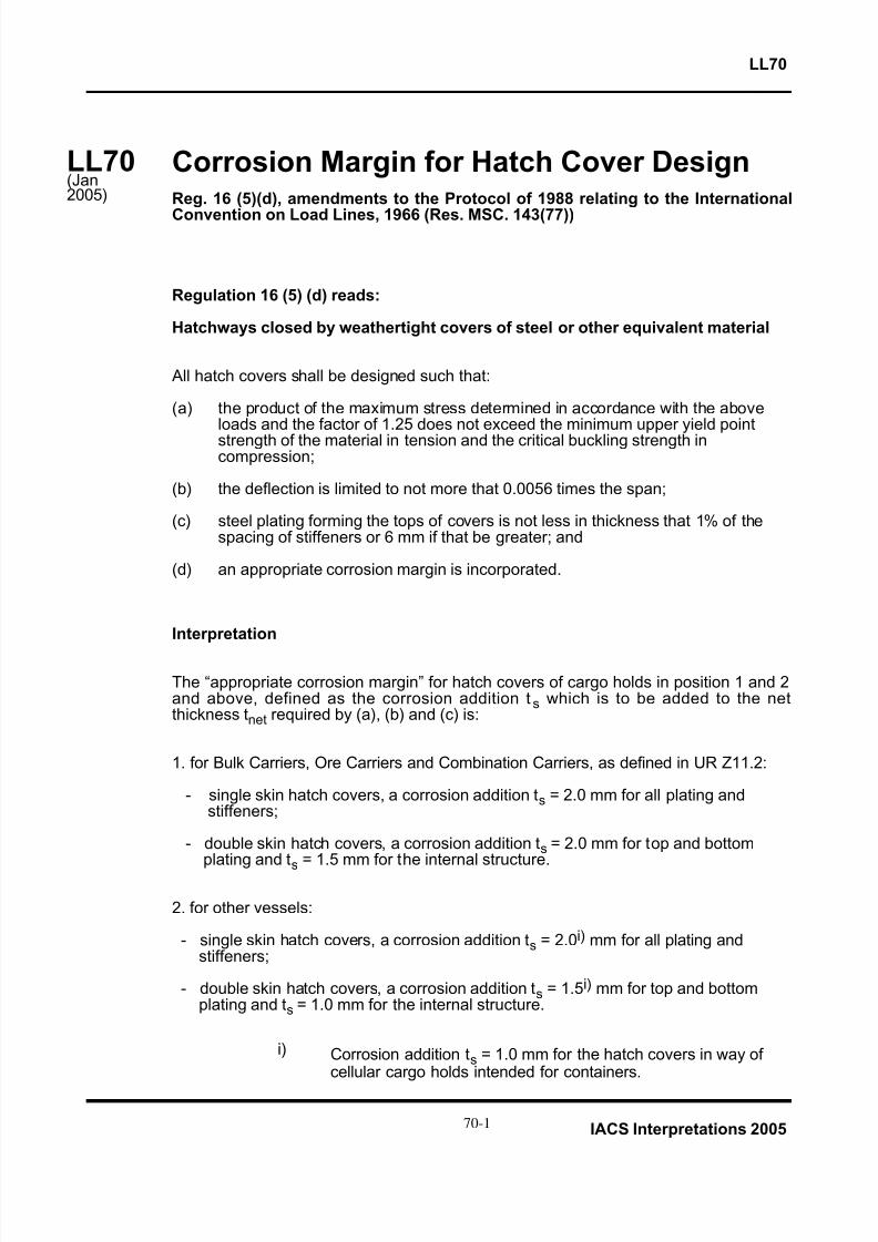
8/12/2019 loadline interpretion
http://slidepdf.com/reader/full/loadline-interpretion 100/137
Corrosion Margin for Hatch Cover DesignReg. 16 (5)(d), amendments to the Protocol of 1988 relating to the International
Convention on Load Lines, 1966 (Res. MSC. 143(77))
Regulation 16 (5) (d) reads:
Hatchways closed by weathertight covers of steel or other equivalent material
All hatch covers shall be designed such that:
(a) the product of the maximum stress determined in accordance with the aboveloads and the factor of 1.25 does not exceed the minimum upper yield pointstrength of the material in tension and the critical buckling strength incompression;
(b) the deflection is limited to not more that 0.0056 times the span;
(c) steel plating forming the tops of covers is not less in thickness that 1% of thespacing of stiffeners or 6 mm if that be greater; and
(d) an appropriate corrosion margin is incorporated.
Interpretation
The “appropriate corrosion margin” for hatch covers of cargo holds in position 1 and 2and above, defined as the corrosion addition ts which is to be added to the netthickness tnet required by (a), (b) and (c) is:
1. for Bulk Carriers, Ore Carriers and Combination Carriers, as defined in UR Z11.2:
- single skin hatch covers, a corrosion addition ts = 2.0 mm for all plating andstiffeners;
- double skin hatch covers, a corrosion addition ts = 2.0 mm for top and bottomplating and t
s= 1.5 mm for the internal structure.
2. for other vessels:
- single skin hatch covers, a corrosion addition ts = 2.0i) mm for all plating andstiffeners;
- double skin hatch covers, a corrosion addition ts = 1.5i) mm for top and bottomplating and ts = 1.0 mm for the internal structure.
i) Corrosion addition ts = 1.0 mm for the hatch covers in way ofcellular cargo holds intended for containers.
LL70(Jan2005)
LL70
IACS Interpretations 200570-1

8/12/2019 loadline interpretion
http://slidepdf.com/reader/full/loadline-interpretion 101/137
The above corrosion margins have been defined based on the assumption that
corrosion protection and renewals as given in UR S21.6.1 is complied with for all shiptypes subject to regulation 16 (5) (d) of the 1988 Load Line Protocol.
For corrosion addition ts = 1.0 mm it is assumed that the thickness for steel renewal istnet and the thickness for coating or annual gauging is tnet + 0,5 mm.
Note: This UI LL70 is to be uniformly implemented by IACS Members and Associateson ships constructed (i.e. keel laid) from 1st January 2005.
END
LL70(C’td)
LL70
70-2
IACS Interpretations 2005

8/12/2019 loadline interpretion
http://slidepdf.com/reader/full/loadline-interpretion 102/137
Page 1 of 3
“FAQ”
(Note: This paper is prepared by IACS for external use. 16 August 2005).
Hatch Cover Design for General Cargo Ships andContainer Ships
Question 1
Bulk Carriers
IACS S21 Rev.3 (April 2003) entered into force on 1 January 2004, andapplies to ships contracted for construction on or after 1 January 2004.
When the bulk carrier hatch covers are designed according to IACS S21Rev.3 (April 2003), do they also fulfil the MSC.143 (77) Annex 3 –Regulation 16 requirements?
Answer
It is confirmed that when bulk carrier hatch covers are designed according toIACS UR S21 Rev.3 (April 2003), they also fulfil the MSC.143 (77) Annex 3 -Regulation 16 requirements.
Question 2
Container Carriers and General Cargo Ships
In Resolution MSC.143 (77) Annex 3 (Adopted on 5 June 2003) –Regulation 16 (5)(d), it is stated that “an appropriate corrosion margin isincorporated’.
Can the same corrosion margin as for the conventional 1.75t/m2 weather

8/12/2019 loadline interpretion
http://slidepdf.com/reader/full/loadline-interpretion 103/137
Page 2 of 3
load (as per the current Classification Rules) be used for this purpose?
Answer
The current version of S21, applicable to bulk carriers, ore carriers andcombination carriers, considers only the sea pressures but a new version ispresently under development for application to all types of ships and at thispurpose also loads other than sea loads will be taken into account.
The unified requirements that will be developed by IACS for the design of hatchcovers will be based on a net scantling approach.
The corrosion additions in UR S21 to be used also for other types of ships will be
the same as the ones presently adopted for bulk carriers.
Until the new version of UR S21 is adopted by IACS, hatch covers for shipsdifferent from bulk carriers, ore carriers and combination carriers are to bedesigned in accordance with:
- the requirements of ILLC, as far as sea loads are concerned ;
- the current Classification Societies Rules.
Question 3
Container Carriers – special features
Interpretation of Resolution MSC.143 (77) Annex 3 (Adopted on 5 June2003) – Regulation 16 – Table 16.2 for Container Carriers withL>100m:
Can the following interpretation be applied?
Longitudinal positionFP 0.25L Aft of 0.25L
L>100m
Freeboard Deck Equation in 16 (2)(a) 3.5 t/m2 3.5 t/m2
1st superstructure deck 3.5 t/m2 3.5 t/m2 2.6 t/m2
2nd superstructure deck 2.6 t/m2 2.6 t/m2 2.1 t/m2
3rd superstructure deck 2.1 t/m2 2.1 t/m2 2.1 t/m2
8/12/2019 loadline interpretion
http://slidepdf.com/reader/full/loadline-interpretion 104/137
Page 3 of 3
Answer
The design loads can be reduced from 2,6 t/m2 to 2,1 t/m2, as proposed above,for locations other than positions 1 and 2, as defined in ILLC.
The following considerations have been given for accepting a load reduction:
- Position 2 is defined in the Amendments to the Protocol of 1988 withrespect to the exposed superstructure decks.
- The meaning of "located at least one (or two, when forward of 0,25L
from forward perpendicular) standard height of superstructure abovethe freeboard deck", relevant to the "position 2" definition, should beinterpreted as: decks of superstructures having height less than one(two) standard height(s) of superstructure are to be considered asbeing in "position 1".
In conclusion, locations more than two (or three, when forward of 0,25L fromforward perpendicular) standard height of superstructure above the freeboarddeck are not position 2 and the design loads in these locations may be reducedwith respect to those specified in ILLC.
Question 4
To determine the hatch cover location, can we use the “assumedfreeboard deck” as defined in IACS UI LL64?
Answer
It is confirmed that LL 64 is to be used to determine the hatch cover location.
END
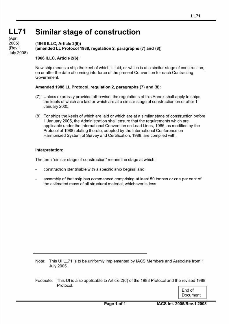
8/12/2019 loadline interpretion
http://slidepdf.com/reader/full/loadline-interpretion 105/137
LL71
Page 1 of 1 IACS Int. 2005/Rev.1 2008
LL
(cont)
Similar stage of construction
(1966 ILLC, Article 2(6))(amended LL Protocol 1988, regulation 2, paragraphs (7) and (8))
1966 ILLC, Article 2(6):
New ship means a ship the keel of which is laid, or which is at a similar stage of construction,on or after the date of coming into force of the present Convention for each ContractingGovernment.
Amended 1988 LL Protocol, regulation 2, paragraphs (7) and (8):
(7) Unless expressly provided otherwise, the regulations of this Annex shall apply to ships
the keels of which are laid or which are at a similar stage of construction on or after 1January 2005.
(8) For ships the keels of which are laid or which are at a similar stage of construction before
1 January 2005, the Administration shall ensure that the requirements which areapplicable under the International Convention on Load Lines, 1966, as modified by the
Protocol of 1988 relating thereto, adopted by the International Conference onHarmonized System of Survey and Certification, 1988, are complied with.
Interpretation:
The term “similar stage of construction” means the stage at which:
- construction identifiable with a specific ship begins; and
- assembly of that ship has commenced comprising at least 50 tonnes or one per cent of
the estimated mass of all structural material, whichever is less.
Note: This UI LL71 is to be uniformly implemented by IACS Members and Associate from 1
July 2005.
Footnote: This UI is also applicable to Article 2(6) of the 1988 Protocol and the revised 1988
Protocol.
LL71(April2005)(Rev.1July 2008)
End of Document

8/12/2019 loadline interpretion
http://slidepdf.com/reader/full/loadline-interpretion 106/137
Interpretation to ICLL Regulation 27
Regulation
Regulation 27(3) reads:
A type "A" ship, if over 150 m in length, and designed to have empty compartmentswhen loaded to her summer load water line, shall be able to withstand the flooding of any one of these empty compartments at an assumed permeability of 0.95, and remainafloat in a condition of equilibrium considered to be satisfactory by the Administration.In such a ship, if over 225 m in length, the machinery space shall be treated as afloodable compartment but with a permeability of 0,85.
Interpretation
Members apply resolution A.320(IX) when certifying ships of non 1988 Protocol Partiesunder regulations 27(3) of the 1966 ICCL.
Note:This UI is to be uniformly implemented by IACS Members and Associates to ships
constructed on or after 1 January 2006.
▼
LL72(Sept 2005)
▼
IACS Interpretations 2005 72-1
LL72
8/12/2019 loadline interpretion
http://slidepdf.com/reader/full/loadline-interpretion 107/137
LL74
Page 1 of 1 IACS Int. 2008
SC
(cont)
Measurement of Distances
Several IMO instruments (e.g., ICLL, SOLAS and MARPOL Conventions, the IBC Code andthe IGC Code, etc.) require distances to be measured such as tank length, height, width, ship(or subdivision or waterline) length, etc..
Interpretation
Unless explicitly stipulated otherwise in the text of the regulations in SOLAS, Load Line andMARPOL Conventions and any of their mandatory Codes, distances are to be measured byusing moulded dimensions.
Note:
This Unified Interpretation is to be uniformly implemented by IACS Societies from 1 April2009.
SC224(Aug 2008)
LL74(Aug 2008)
MPC95(Aug 2008)
End of Document

8/12/2019 loadline interpretion
http://slidepdf.com/reader/full/loadline-interpretion 108/137
LL75
Page 1 of 1 IACS Int. 2008/Rev.1 2009
SC
(cont)
Permeability of Store Space in the DamageStability Calculation(Regulation 27(3) & (8.d))
Regulation
1. Reg.27(3) of 1988 protocol of 1966 ICLL and its amendment MSC.143(77) reads:
“(3) A type ‘A’ ship, if over 150 m in length, to which a freeboard less than type ‘B’ has been assigned, when loaded in accordance with the requirements of paragraph(11), shall be able to withstand the flooding of any compartment or compartments,with an assumed permeability of 0.95, consequent upon the damage assumptionsspecified in paragraph (12), and shall remain afloat in a satisfactory condition of
equilibrium, as specified in paragraph (13). In such a ship, the machinery space shall be treated as a floodable compartment, but with a permeability of 0.85.”
2. Reg.27(8.d) of 1988 protocol of 1966 ICLL and its amendment MSC.143(77) reads:
“the ship, when loaded in accordance with the requirements of paragraph (11), shall
be able to withstand the flooding of any compartment or compartments, with anassumed permeability of 0.95, consequent upon the damage assumptions specified in
paragraph (12), and shall remain afloat in a satisfactory condition of equilibrium, asspecified in paragraph (13). In such a ship, if over 150 m in length, the machinery
space shall be treated as a floodable compartment, but with a permeability of 0.85.”
Interpretation
The permeability assumed in the damage stability calculation for the flooding of any storespace shall be 0.95 under 1988 Protocol of 1966 ICLL.
Note:
1. This Unified Interpretation is to be uniformly implemented by IACS Members and Associates for ships contracted for construction on or after 1 July 2009.
2. The “contracted for construction” date means the date on which the contract to buildthe vessel is signed between the prospective owner and the shipbuilder. For further details regarding the date of “contract for construction”, refer to IACS ProceduralRequirement (PR) No. 29.
LL75(Sept2008)(Rev.1Mar 2009)
End of
Document

8/12/2019 loadline interpretion
http://slidepdf.com/reader/full/loadline-interpretion 109/137
SC234, LL76 and MPC96
Page 1 of 3 IACS Int. 2009/Rev.1 2014
SC234(cont)
LL76(cont)
MPC96(cont)
SC234(Apr 2009)(Corr.1 Jul2010)(Rev.1
Feb 2014)
LL76(Apr 2009)(Corr.1 Jul2010)(Rev.1
Feb 2014)
MPC96(Apr 2009)(Corr.1 Jul2010)(Rev.1Feb 2014)
Initial Statutory Surveys at New Construction
1. Scope
The scope of this UI is to define the requirements for the initial statutory surveys at new
construction as detailed in IMO Resolution A.1053(27), which are not addressed in UR Z23for the following as applicable:-
(i) International Load Line Certificate (1966)
(ii) Cargo Ship Safety Equipment Certificate
(iii) International Oil Pollution Prevention Certificate
This UI only covers the survey activities required and does not cover the technicalinterpretations of the statutory requirements or approval of plans, designs and manualsrequired by the Regulations.
2. This UI does not cover the requirements for type approval or certification at vendor’sworks and for which evidence of acceptance is to be provided as indicated in the survey
tables.
Note:
1. This UI is to be uniformly implemented by IACS Societies on ships contracted for construction (as defined in IACS PR 29) from 1st July 2010.
2. Rev.1 of this UI is to be uniformly implemented by IACS Societies on ships contracted
for construction (as defined in IACS PR 29) from 1 July 2014.
3. The “contracted for construction” date means the date on which the contract to build thevessel is signed between the prospective owner and the shipbuilder. For further details
regarding the date of “contract for construction”, refer to IACS Procedural Requirement(PR) No. 29.

8/12/2019 loadline interpretion
http://slidepdf.com/reader/full/loadline-interpretion 110/137
SC234, LL76 and MPC96
Page 2 of 3 IACS Int. 2009/Rev.1 2014
SC234(cont)
LL76(cont)
MPC96(cont)
3. Definitions used in the survey tables
Survey Item A description of the survey item considered
Origin of the Requirement Applicable Statutory Regulation
Approved Drawings/Documentation
Indicates whether approved drawings/documentation is required
Conformity Verification This verification may consist of an examination of the certificate, acheck of the marks or, for products which require type approval, toverify conformity of the product with the approved prototype or certification with Flag Administration requirements
Survey during construction or installation
Indicates whether the witness by surveyor of construction andinstallation on board is required
Tightness Testing Indicates whether tightness testing is required to be witnessed bythe surveyor for survey item
Survey after construction or installation
Indicates whether the survey item is examined by the Surveyor after completion of its construction and installation on board
Function Test Indicates whether a survey item or system is to be subjected to afunctioning and/or performance test or trial in the presence of aSurveyor after installation on board
Onboard Verification of documentation
Indicates whether the required documentation is to be verified onboard by the surveyor
Series of Vessels As defined by IACS PR 29
4. Application
This UI applies to all vessels for which the statutory certificates listed in paragraph 1 are to beissued at new construction by IACS Societies.
5. Interpretation of the survey requirements are given in Appendix 1
Table 1 – Safety Equipment
Table 2 – Load Line
Table 3 – MARPOL Annex 1
6. Specific flag administration requirements, if any, supersede the requirementscontained in this UI.
7. Qualification and monitoring of personnel
The surveys required by this UI shall be carried out by exclusive surveyors of theclassification society, as defined in PR5. The surveyors are to be qualified to be able to carry
out the tasks and procedures are to be in place to ensure that their activities are monitored.Details are specified in PR6 and PR7.

8/12/2019 loadline interpretion
http://slidepdf.com/reader/full/loadline-interpretion 111/137

8/12/2019 loadline interpretion
http://slidepdf.com/reader/full/loadline-interpretion 112/137
Appendix 1 to UIs SC234, LL76 & MPC96
Page 1 of 23
Appendix 1 to UIs SC234, LL76 & MPC96
1. Description
1 A.1053(27) Requirements
2 Survey Item A description of the survey item considered
3 Origin of the Requirement Applicable Statutory Regulation
4Correspondence with ApprovedDrawings/Documentation
Indicates whether approved drawings/documentation isrequired
5 Conformity Verification
This verification may consist of an examination of thecertificate, a check of the marks or, for type approved products, to verify conformity of the product with the
approved prototype or certification with NationalRequirements
6 Survey during construction orinstallation
Indicates whether the witness by surveyor of fabrication andinstallation on board is required
7 Tightness TestingIndicates whether tightness testing is required to be witnessed by the surveyor for survey item
8Survey after construction orinstallation
Indicates whether the survey item is examined by theSurveyor after completion of its installation on board and/or
9 Function TestIndicates whether a system is to be subjected to a functioningand/or performance test or trial in the presence of a Surveyor
after installation on board
10Onboard Verification ofdocumentation
Indicates whether the required documentation is to be verifiedon board by the surveyor

8/12/2019 loadline interpretion
http://slidepdf.com/reader/full/loadline-interpretion 113/137
Appendix 1 to UIs SC234, LL76 & MPC96 / Table 1.
Page 2 of 23
Table 1. Safety Equipment
A.1053(27) REQUIREMENT SURVEY ITEMORIGIN OF THE
REQUIREMENT
C O
R R E S P O N D E N C E W I T H
A P
P R O V E D D R A W I N G S /
D O
C U M E N T A T I O N
C O
N F O R M I T Y
V E
R I F I C A T I O N
I N S P E C T I O N S D U R I N G
I N S T A L L A T I O N
I N S P E C T I O N A F T E R
I N S T A L L A T I O N
O N
B O A R D V E R I F I C A T I O N
O F
D O C U M E N T A T I O N
F U
N C T I O N T E S T
(EI)
1.1.3.1
examining the fire pumps and fire main and the disposition of the
hydrants, hoses and nozzles and the international shore connection
and checking that each fire pump, including the emergency fire
pump, can be operated separate ly so that two jets of water are
produced simultaneously from different hydrants at any part of the
ship whilst the required pressure is maintained in the fire main
Fire Pumps
(SOLAS 74/00 reg.II-
2/10.2 FSSC chs.2
and 12) (SOLAS
74/88 regs.II-2/4 and
19)
X X X X
Fire Mains X X
Hydrants X X
Hoses and Nozzles X X X
International Shore Connection X X
(EI)
1.1.3.2examining the provision and disposition of the fire extinguishers Fire Extinguishers
(SOLAS 74/00 reg.II-
2/10.3 FSSC ch.4)
(SOLAS 74/88 reg.II-
2/17)
X X X
(EI)
1.1.3.3
examining the fire fighters’ outfits and emergency escape breathing
devices - EEBDs -
Fire Fighters' Outfits (SOLAS 74/00
regs.II-2/10.10, 13.3.4
and 13.4.3 FSSC
ch.3) (SOLAS 74/88
reg.II-2/17) (BCH
Code ch.III Part E)
X X X
EEBDs - Emergency Escape
Breathing DevicesX X X
(EI)
1.1.3.4
checking the operational readiness and maintenance of fire-fighting
systems
Operational Readiness and
Maintenance of Fire-fighting
System
(SOLAS 74/00 reg.II-
2/14.1) (SOLAS
74/88 reg.II-2/21)
X
(EI)
1.1.3.5
examining the fixed fire-fighting system for the machinery, cargo,
vehicle, special category and ro-ro spaces, as appropriate, and
confirming that the installation tests have been satisfactorily
completed and that its means of operation are clearly marked
Fixed Fire fighting systems
(SOLAS 74/00/08
regs.II-2/10.4, 10.5,
10.7 and 20.6.1,
FSSC chs.5 to 7)
(SOLAS 74/88
regs.II-2/7 and 53)
X X X X X
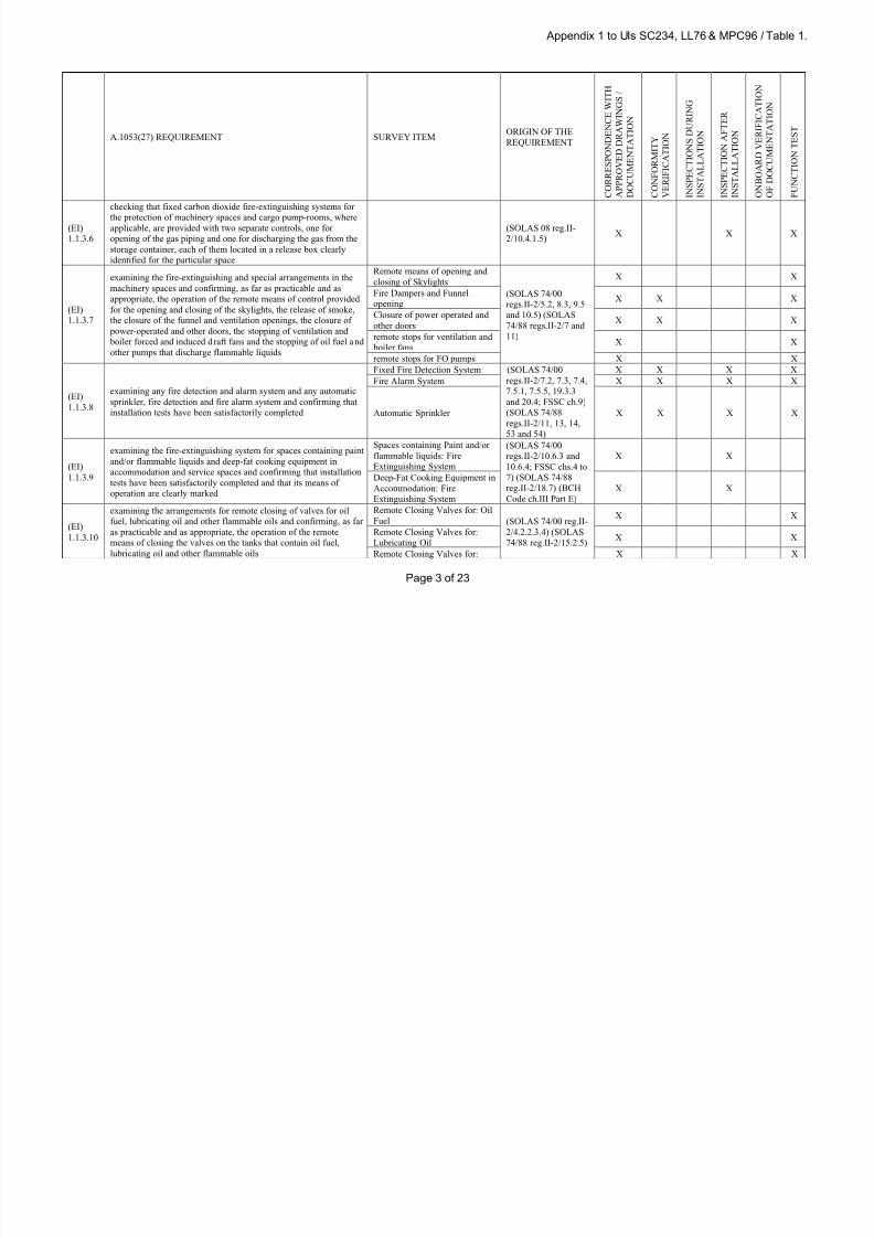
8/12/2019 loadline interpretion
http://slidepdf.com/reader/full/loadline-interpretion 114/137

8/12/2019 loadline interpretion
http://slidepdf.com/reader/full/loadline-interpretion 115/137
Appendix 1 to UIs SC234, LL76 & MPC96 / Table 1.
Page 4 of 23
A.1053(27) REQUIREMENT SURVEY ITEMORIGIN OF THE
REQUIREMENT
C O R R E S P O N D E N C E W I T H
A P P R O V E D D R A W I N G S /
D O C U M E N T A T I O N
C O N F O R M I T Y
V E R I F I C A T I O N
I N S P E C T I O N S D U R I N G
I N S T A L L A T I O N
I N S P E C T I O N A F T E R
I N S T A L L A T I O N
O N B O A R D V E R I F I C A T I O N
O F D O C U M E N T A T I O N
F U N C T I O N T E S T
Other Flammable Oils
(EI)
1.1.3.11
examining the fire protection arrangements in cargo, vehicle and
ro-ro spaces and confirming, as far as practicable and as
appropriate, the operation of the means for closing the various
openings
Fire Detection and Alarmsystem
(SOLAS 74/00
regs.II-2/10.7, 20.2.1,
20.3 and 20.6.2)
(SOLAS 74/88 reg.II-
2/53)
X X X X
Fixed Fire Extinguishing
SystemX X
Structural Fire Protection X X X
Precaution against ignition of
flammable vapours in closed
vehicle spaces, closed ro-ro
spaces and special category
spaces
X X X
(EI)
1.1.3.12
examining, when appropriate, the special arrangements for carrying
dangerous goods, including checking the electrical equipment and
wiring, the ventilation, the provision of protective clothing and
portable appliances and the testing of the water supply, bi lge
pumping and any water spray system
Water Supply
(SOLAS 74/00/08
reg.II-2/19 (except
19.3.8, 19.3.10 and
19.4) FSSC chs.9 and
10) (SOLAS 74/88
reg.II-2/54)
X X
Sources of Ignition X X X
Detection System X X X
Ventilation X X
Bilge system X X
Personnel Protection X X X
Fire Extinguishers X X X
Insulation of Machinery space
boundariesX X X
Water Spray System X X X X X
(EI)
1.1.3.13
checking that the life-saving appliances are of international or vivid
reddish orange, or a comparably highly visible colour on all parts
where this will assist detection at sea
(LSA Code section
1.2.2.6)X
(EI)
1.1.3.14
checking the provision and disposition of the survival craft, where
applicable, marine evacuation systems and rescue boats
Survival Craft Provision and
Disposition (SOLAS 74/88
regs.III/11 to 16 and
31; LSA Code section
6.2)
X X X
Rescue Boat Provision and
DispositionX X X
Marine Evacuation Systems
Provision and DispositionX X X
(EI)
1.1.3.15deployment of 50% of the MES after installation
Deployment of Marine
Evacuation Systems
(LSA Code paragraph
6.2.2.2)X

8/12/2019 loadline interpretion
http://slidepdf.com/reader/full/loadline-interpretion 116/137
Appendix 1 to UIs SC234, LL76 & MPC96 / Table 1.
Page 5 of 23
A.1053(27) REQUIREMENT SURVEY ITEMORIGIN OF THE
REQUIREMENT
C O R R E S P O N D E N C E W I T H
A P P R O V E D D R A W I N G S /
D O C U M E N T A T I O N
C O N F O R M I T Y
V E R I F I C A T I O N
I N S P E C T I O N S D U R I N G
I N S T A L L A T I O N
I N S P E C T I O N A F T E R
I N S T A L L A T I O N
O N B O A R D V E R I F I C A T I O N
O F D O C U M E N T A T I O N
F U N C T I O N T E S T
(EI)
1.1.3.16
examining each survival craft, including its equipment. For liferafts
provided for easy side to side t ransfer, verifying that they are l ess
than 185 kg
Survival Craft Design (SOLAS 74/88
reg.III/31 LSA Codesections 2.5, 3.1 to
3.3 and 4.1 to 4.9)
(SOLAS 74/00
reg.III/31.1);
X X
Survival Craft Engine X X
Survival Craft Equipment X X
(EI)
1.1.3.17
examining the embarkation arrangements for each survival craft
and the testing of each launching appliance, including overload
tests, tests to establish the lowering speed and the lowering of each
survival craft to the water with the ship at its lightest sea-going
draught, and, where applicable, launching underway at 5 knots,
checking the recovery of each lifeboat
Survival Craft Launching and
Recovery appliances (SOLAS 74/00
regs.III/11, 12, 13, 16,
31 and 33 LSA Code
section 6.1)
X X X
Survival Craft Embarkation
ArrangementsX X X
(EI)
1.1.3.18
examining the embarkation arrangements for each marine
evacuation device, where applicable, and the launching
arrangements, including inspection for lack of side shell opening
between the embarkation sta tion and waterline, review of di stance
to the propeller and other life-saving appliances and ensuring that
the stowed position is protected from heavy weather damage, as
much as practicable
MES Launching and Recovery
appliances
(SOLAS 74/00
reg.III/15; LSA Code
section 6.2)
X X X X
MES Embarkation
ArrangementsX X
(EI)
1.1.3.19
examining each rescue boat, including its equipment. For inflatable
rescue boats, confirming that they are stowed in a fully inflatedcondition
Rescue Boat Design (SOLAS 74/88
regs.III/14 and 31;
LSA Code sections2.5, 5.1 and 6.1)
X X
Rescue Boat Engine X X X
Rescue Boat Equipment X X
(EI)
1.1.3.20
examining the embarkation and recovery arrangements for each
rescue boat and testing each launching and recovery appliance,
including overload tests, tests to establish the lowering and
recovery speeds and ensuring that each rescue boat can be lowered
to the water and recovered with the ship at its lightest sea-going
draught, launching underway at 5 knots
Rescue Boat Launching and
Recovery appliances and
Arrangements
(SOLAS 74/88
regs.III/14, 17 and 31;
LSA Code section
6.1)
X X X
(EI)
1.1.3.21
testing that the engine of the rescue boat(s) and of each lifeboat,
when so fitted, start satisfactorily and operate both ahead and astern
Test of engines of lifeboat and
Rescue Boat
(SOLAS 74/00
reg.III/19)X

8/12/2019 loadline interpretion
http://slidepdf.com/reader/full/loadline-interpretion 117/137
Appendix 1 to UIs SC234, LL76 & MPC96 / Table 1.
Page 6 of 23
A.1053(27) REQUIREMENT SURVEY ITEMORIGIN OF THE
REQUIREMENT
C O R R E S P O N D E N C E W I T H
A P P R O V E D D R A W I N G S /
D O C U M E N T A T I O N
C O N F O R M I T Y
V E R I F I C A T I O N
I N S P E C T I O N S D U R I N G
I N S T A L L A T I O N
I N S P E C T I O N A F T E R
I N S T A L L A T I O N
O N B O A R D V E R I F I C A T I O N
O F D O C U M E N T A T I O N
F U N C T I O N T E S T
(EI)1.1.3.22
confirming that there are posters or signs in the vicinity of survival
craft and their launching stations and containers, brackets, racksand other similar stowage locations for life-saving equipment
Posters or Signs (SOLAS 74/88regs.III/9 and 20) X
(EI)
1.1.3.23
examining the provision and stowage and checking the operation of
portable onboard communications equipment, if provided, and two-
way VHF radiotelephone apparatus and search and rescue locating
devices
Two-way VHF radiotelephone
apparatus(SOLAS 74/88
regs.II-2/12.2 and
III/6)
X X X
Search and rescue locating
devicesX X X
(EI)
1.1.3.24
examining the provision and stowage of the distress flares and the
line-throwing appliance, checking the provision and operation of
fixed on board communications equipment, if provided, and testing
the means of operation of the general alarm system
Distress Flares and Line-
Throwing Appliances(SOLAS 74/00
regs.III/6 and 18;
LSA Code sections
3.1, 7.1 and 7.2)
X X
On board Communications
equipmentX X X
General Alarm System X X X
(EI)
1.1.3.25
examining the provision, disposition and stowage of the lifebuoys,
including those fitted with self-igniting lights, self-activating
smoke signals and buoyant lines, lifejackets, immersion suits and
anti-exposure suits
Lifebuoys
(SOLAS 74/00/06
regs.III/7 and 32 to
37; LSA Code
sections 2.1, 2.5 and
3.3)
X X X
Lifebuoys fitted with self-
igniting lightsX X X
Lifebuoys fitted with self-
activating smoke signalsX X X
Lifebuoys fitted with buoyant
linesX X X
Lifejackets X X X
Immersion suits X X X
Anti-exposure suits X X X

8/12/2019 loadline interpretion
http://slidepdf.com/reader/full/loadline-interpretion 118/137
Appendix 1 to UIs SC234, LL76 & MPC96 / Table 1.
Page 7 of 23
A.1053(27) REQUIREMENT SURVEY ITEMORIGIN OF THE
REQUIREMENT
C O R R E S P O N D E N C E W I T H
A P P R O V E D D R A W I N G S /
D O C U M E N T A T I O N
C O N F O R M I T Y
V E R I F I C A T I O N
I N S P E C T I O N S D U R I N G
I N S T A L L A T I O N
I N S P E C T I O N A F T E R
I N S T A L L A T I O N
O N B O A R D V E R I F I C A T I O N
O F D O C U M E N T A T I O N
F U N C T I O N T E S T
(EI)
1.1.3.26
checking the lighting of the muster and embarkation stations and
the alleyways, stairways and exits giving access to the muster and
embarkation stations, including when supplied from the emergency
source of power
Muster and Embarkation Station
Lighting
(SOLAS 74/88
regs.II-1/43 and
III/11)
X XAlleyways and Stairways
LightingX X
Exits giving Access to the
Muster and Embarkation
Stations Lighting
X X
Muster and Embarkation Station
Lighting from Emergency
Source of Power
X X
Alleyways and Stairways
Lighting from Emergency
Source of Power
X X
Exits giving Access to the
Muster and Embarkation
Stations Lighting from
Emergency Source of Power
X X
(EI)
1.1.3.27
examining the provision and positioning and checking the
operation of, as appropriate, the navigation lights, shapes and
sound signalling equipment
Navigation Lights (International
Regulations for
Preventing Collisions
at Sea (COLREG) in
force, regs.20 to 24,27 to 30 and 33)
X X X X
Shapes and Sounds signalling
equipment
X X X
(EI)
1.1.3.28
checking that the minimum safe distances from the steering and
standard magnetic compasses for all electrical equipment are
complied with
Bridge(SOLAS 74/00
regs.V/17 and 19)X
(EI)
1.1.3.29
checking the electromagnetic compatibility of electrical and
electronic equipment on or in the vicinity of the bridgeBridge
(SOLAS 74/00
reg.V/17)X X

8/12/2019 loadline interpretion
http://slidepdf.com/reader/full/loadline-interpretion 119/137
Appendix 1 to UIs SC234, LL76 & MPC96 / Table 1.
Page 8 of 23
A.1053(27) REQUIREMENT SURVEY ITEMORIGIN OF THE
REQUIREMENT
C O R R E S P O N D E N C E W I T H
A P P R O V E D D R A W I N G S /
D O C U M E N T A T I O N
C O N F O R M I T Y
V E R I F I C A T I O N
I N S P E C T I O N S D U R I N G
I N S T A L L A T I O N
I N S P E C T I O N A F T E R
I N S T A L L A T I O N
O N B O A R D V E R I F I C A T I O N
O F D O C U M E N T A T I O N
F U N C T I O N T E S T
(EI)
1.1.3.30
checking, as appropriate, the provision and operation of the
following ship borne navigational systems equipment
(EI)
1.1.3.30
.1
the magnetic compass, including examining the sighting,
movement, illumination and a pylorus or compass bearing device
Navigation Equipment:
Magnetic Compass (SOLAS 74/00
reg.V/19)
X X
Navigation Equipment: Pylorus
or Compass Bearing DeviceX X
(EI)
1.1.3.30
.2
nautical charts and nautical publications necessary for the intended
voyage are available and have been updated, and, where an
electronic chart display and information system (ECDIS) is used,
the electronic charts have been updated and the required back-up
system is provided and updated
Navigation Equipment: ECDIS
including back-up arrangements(SOLAS 74/00/09
reg.V/19)
X X
Nautical Charts and Nautical
PublicationsX
(EI)
1.1.3.30
.3
global navigation satellite system receiver or terrestrial radio
navigation system
Navigation Equipment: GNSS
receiverX X
(EI)
1.1.3.30
.4
sound reception system, when bridge is totally enclosed Navigation Equipment: Sound
Reception SystemX X
(EI)
1.1.3.30
.5
means of communication to emergency steering position, where
provided
Navigation Equipment: Means
of communication with
Emergency Steering Position
X X X
(EI)
1.1.3.30.6
spare magnetic compass Navigation Equipment: SpareMagnetic Compass
X X
(EI)
1.1.3.30
.7
daylight signalling lamp Navigation Equipment:
Daylight Signalling LampX X
(EI)
1.1.3.30
.8
echo sounding device Navigation Equipment: Echo-
sounding DeviceX X
(EI)
1.1.3.30
.9
radar(s), including examining the waveguide and cable runs for
routeing and protection and the display unit confirming lighting,
correct operation of all controls, and functions
Navigation Equipment: Radar
InstallationsX X X

8/12/2019 loadline interpretion
http://slidepdf.com/reader/full/loadline-interpretion 120/137
Appendix 1 to UIs SC234, LL76 & MPC96 / Table 1.
Page 9 of 23
A.1053(27) REQUIREMENT SURVEY ITEMORIGIN OF THE
REQUIREMENT
C O R R E S P O N D E N C E W I T H
A P P R O V E D D R A W I N G S /
D O C U M E N T A T I O N
C O N F O R M I T Y
V E R I F I C A T I O N
I N S P E C T I O N S D U R I N G
I N S T A L L A T I O N
I N S P E C T I O N A F T E R
I N S T A L L A T I O N
O N B O A R D V E R I F I C A T I O N
O F D O C U M E N T A T I O N
F U N C T I O N T E S T
(EI)1.1.3.30
.10
electronic plotting aid, automatic tracking aid or automatic radar
plotting aid as appropriate, using the appropriate test fac ilities
Navigation Equipment:
Electronic Plotting Aid X X Navigation Equipment:
Automatic Tracking aid(s) or
Automatic Radar Plotting Aid
X X
(EI)
1.1.3.30
.11
speed and distance measuring devices "through the water" and
"over the ground"
Navigation Equipment: Speed
and Distance measuring DeviceX X
(EI)
1.1.3.30
.12
transmitting heading device providing heading information to
radar, plotting aids and automatic identification system equipment
and voyage data recorder
Navigation Equipment:
Transmitting Heading DeviceX X
(EI)
1.1.3.30
.13
automatic identification system Navigation Equipment: AIS
Automatic Identification SystemX X
(EI)
1.1.3.30
.14
gyrocompass, including examining the alignment of the master and
all repeaters
Navigation Equipment: Gyro
CompassX X
Navigation Equipment: Gyro
Compass RepeatersX X
(EI)
1.1.3.30
.15
rudder angle indicator Navigation Equipment: Rudder
Angle IndicatorX X
(EI)1.1.3.30
.16
propeller rate of revolut ion indicator Navigation Equipment:Propeller rate of Revolution
Indicator
X X
(EI)
1.1.3.30
.17
propeller, operational mode , thrust, and pitch indicator
Navigation Equipment:
Variable-Pitch propeller pitch
and operational mode indicator
X X
(EI)
1.1.3.30
.18
rate-of-turn indicator Navigation Equipment: Rate of
Turn IndicatorX X
(EI)
1.1.3.30
.19
heading or track control system Navigation Equipment: Heading
or Track Control SystemX X
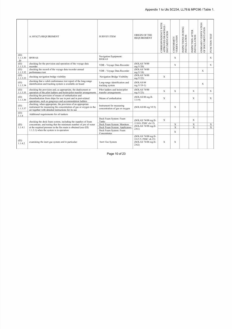
8/12/2019 loadline interpretion
http://slidepdf.com/reader/full/loadline-interpretion 121/137
Appendix 1 to UIs SC234, LL76 & MPC96 / Table 1.
Page 10 of 23
A.1053(27) REQUIREMENT SURVEY ITEMORIGIN OF THE
REQUIREMENT
C O R R E S P O N D E N C E W I T H
A P P R O V E D D R A W I N G S /
D O C U M E N T A T I O N
C O N F O R M I T Y
V E R I F I C A T I O N
I N S P E C T I O N S D U R I N G
I N S T A L L A T I O N
I N S P E C T I O N A F T E R
I N S T A L L A T I O N
O N B O A R D V E R I F I C A T I O N
O F D O C U M E N T A T I O N
F U N C T I O N T E S T
(EI)
1.1.3.30.20
BNWAS Navigation Equipment:BNWAS X X
(EI)
1.1.3.31
checking for the provision and operation of the voyage data
recorderVDR - Voyage Data Recorder
(SOLAS 74/00
reg.V/20)X X
(EI)
1.1.3.32
checking the record of the voyage data recorder annual
performance testVDR - Voyage Data Recorder
(SOLAS 74/00
reg.V/18)X
(EI)
1.1.3.33checking navigation bridge visibility Navigation Bridge Visibility
(SOLAS 74/00
reg.V/22)X
(EI)
1.1.3.34
checking that a valid conformance test report of the long-range
identification and tracking system is available on boardLong-range identification and
tracking system
(SOLAS 04
reg.V/19-1)X
(EI)
1.1.3.35
checking the provision and, as appropriate, the deployment or
operation of the pilot ladders and hoists/pilot transfer arrangements
Pilot ladders and hoists/pilot
transfer arrangements
(SOLAS 74/00
reg.V/23)X X X X
(EI)
1.1.3.36
checking the provision of means of embarkation and
disembarkation from ships for use in port and in port-related
operations, such as gangways and accommodation ladders
Means of embarkation(SOLAS 08 reg.II-
1/3-9)X X X
(EI)
1.1.3.37
checking, when appropriate, the provision of an appropriate
instrument for measuring the concentration of gas or oxygen in the
air together with detailed instructions for its use
Instrument for measuring
concentration of gas or oxygen(SOLAS 08 reg.VI/3) X
(EI)
1.1.4 Additional requirements for oil tankers
(EI)
1.1.4.1
checking the deck foam system, including the supplies of foam
concentrate, and testing that the minimum number of jets of water
at the required pressure in the fire main is obtained (see (EI)
1.1.3.1) when the system is in operation
Deck Foam System: Foam
Tanks(SOLAS 74/00 reg.II-
2/10.8; FSSC ch.15)
(SOLAS 74/88 reg.II-
2/61)
X X
Deck Foam System: Monitors X X X
Deck Foam System: Applicators X X X
Deck Foam System: Foam
ConcentratesX
(EI)
1.1.4.2examining the inert gas system and in particular: Inert Gas System
(SOLAS 74/00 reg.II-
2/4.5.5; FSSC ch.15)
(SOLAS 74/88 reg.II-
2/62)
X X

8/12/2019 loadline interpretion
http://slidepdf.com/reader/full/loadline-interpretion 122/137
Appendix 1 to UIs SC234, LL76 & MPC96 / Table 1.
Page 11 of 23
A.1053(27) REQUIREMENT SURVEY ITEMORIGIN OF THE
REQUIREMENT
C O R R E S P O N D E N C E W I T H
A P P R O V E D D R A W I N G S /
D O C U M E N T A T I O N
C O N F O R M I T Y
V E R I F I C A T I O N
I N S P E C T I O N S D U R I N G
I N S T A L L A T I O N
I N S P E C T I O N A F T E R
I N S T A L L A T I O N
O N B O A R D V E R I F I C A T I O N
O F D O C U M E N T A T I O N
F U N C T I O N T E S T
(EI)
1.1.4.2.1
examining externally for any sign of gas or effluent leakage Signs of Gas or effluentLeakage X X
(EI)
1.1.4.2.
2
confirming the proper operation of both inert gas blowers Inert Gas Blowers X
(EI)
1.1.4.2.
3
observing the operation of the scrubber-room ventilation system Scrubber Room Ventilation X
(EI)
1.1.4.2.
4
checking the deck water seal for automatic filling and draining Deck Water Seal X X
(EI)
1.1.4.2.
5
examining the operation of all remotely operated or automatically
controlled valves and, in particular, the flue gas isolating valves
Remote or Automatic Control
ValvesX
Flue Gas Isolating Valve X X
(EI)
1.1.4.2.
6
observing a test of the interlocking feature of soot blowers Interlocking of soot Blowers X
(EI)
1.1.4.2.
7
observing that the gas pressure-regulating valve automatically
closes when the inert gas blowers are securedGas Pressure-Regulating Valve X
(EI)1.1.4.2.
8
checking, as far as practicable, the following alarms and safetydevices of the inert gas system using simulated conditions where
necessary:
X
(EI)
1.1.4.2.
8.1
high oxygen content of gas in the inert gas mainTest for Alarms and Safety
Devices Inert Gas SystemX
(EI)
1.1.4.2.
8.2
low gas pressure in the inert gas mainTest for Alarms and Safety
Devices Inert Gas SystemX
(EI)
1.1.4.2.
8.3
low pressure in the supply to the deck water sealTest for Alarms and Safety
Devices Inert Gas SystemX
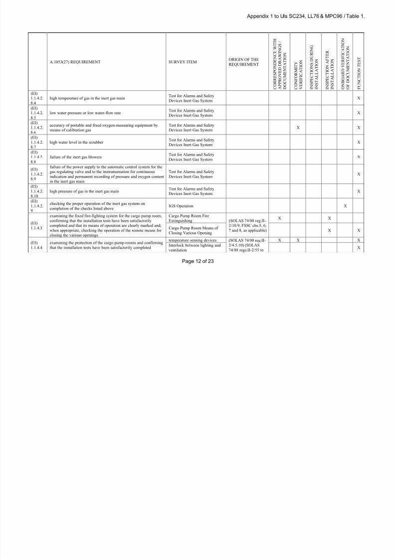
8/12/2019 loadline interpretion
http://slidepdf.com/reader/full/loadline-interpretion 123/137
Appendix 1 to UIs SC234, LL76 & MPC96 / Table 1.
Page 12 of 23
A.1053(27) REQUIREMENT SURVEY ITEMORIGIN OF THE
REQUIREMENT
C O R R E S P O N D E N C E W I T H
A P P R O V E D D R A W I N G S /
D O C U M E N T A T I O N
C O N F O R M I T Y
V E R I F I C A T I O N
I N S P E C T I O N S D U R I N G
I N S T A L L A T I O N
I N S P E C T I O N A F T E R
I N S T A L L A T I O N
O N B O A R D V E R I F I C A T I O N
O F D O C U M E N T A T I O N
F U N C T I O N T E S T
(EI)
1.1.4.2.8.4
high temperature of gas in the inert gas main Test for Alarms and SafetyDevices Inert Gas System X
(EI)
1.1.4.2.
8.5
low water pressure or low water-flow rateTest for Alarms and Safety
Devices Inert Gas SystemX
(EI)
1.1.4.2.
8.6
accuracy of portable and fixed oxygen-measuring equipment by
means of calibration gas
Test for Alarms and Safety
Devices Inert Gas SystemX X
(EI)
1.1.4.2.
8.7
high water level in the scrubberTest for Alarms and Safety
Devices Inert Gas SystemX
(EI)
1.1.4.2.
8.8
failure of the inert gas blowersTest for Alarms and Safety
Devices Inert Gas SystemX
(EI)
1.1.4.2.
8.9
failure of the power supply to the automatic control system for the
gas regulating valve and to the instrumentation for continuous
indication and permanent recording of pressure and oxygen content
in the inert gas main
Test for Alarms and Safety
Devices Inert Gas SystemX
(EI)
1.1.4.2.
8.10
high pressure of gas in the inert gas mainTest for Alarms and Safety
Devices Inert Gas System
X
(EI)
1.1.4.2.
9
checking the proper operation of the inert gas system on
completion of the checks listed aboveIGS Operation X
(EI)
1.1.4.3
examining the fixed fire-fighting system for the cargo pump room,
confirming that the installation tests have been satisfactorily
completed and that its means of operation are clearly marked and,
when appropriate, checking the operation of the remote means for
closing the various openings
Cargo Pump Room Fire
Extinguishing (SOLAS 74/00 reg.II-
2/10.9; FSSC chs.5, 6,
7 and 8, as applicable)
X X
Cargo Pump Room Means of
Closing Various OpeningX X
(EI)
1.1.4.4
examining the protection of the cargo pump-rooms and confirming
that the installation tests have been satisfactorily completed
temperature sensing devices (SOLAS 74/00 reg.II-
2/4.5.10) (SOLAS
74/88 regs.II-2/55 to
X X X
Interlock between lighting and
ventilationX

8/12/2019 loadline interpretion
http://slidepdf.com/reader/full/loadline-interpretion 124/137
Appendix 1 to UIs SC234, LL76 & MPC96 / Table 1.
Page 13 of 23
A.1053(27) REQUIREMENT SURVEY ITEMORIGIN OF THE
REQUIREMENT
C O R R E S P O N D E N C E W I T H
A P P R O V E D D R A W I N G S /
D O C U M E N T A T I O N
C O N F O R M I T Y
V E R I F I C A T I O N
I N S P E C T I O N S D U R I N G
I N S T A L L A T I O N
I N S P E C T I O N A F T E R
I N S T A L L A T I O N
O N B O A R D V E R I F I C A T I O N
O F D O C U M E N T A T I O N
F U N C T I O N T E S T
monitoring of hydrocarbon gas 58) X X
Bilge monitoring X
(EI)
1.1.5.1
confirming that the fire control plans are permanently exhibited or,
alternatively, emergency booklets have been provided and that a
duplicate of the plans or the emergency booklet are available in a
prominently marked enclosure exte rnal to the ship's deckhouse
Required Documentations
(SOLAS 74/00 reg.II-
2/15.2.4) (SOLAS
74/88 reg.II-2/20)
X
(EI)
1.1.5.2confirming that maintenance plans have been provided Required Documentations
(SOLAS 74/00
regs.II-2/14.2.2 and
14.4)
X
(EI)
1.1.5.3
confirming that the training manuals and the fire safety operational
booklets have been providedRequired Documentations
(SOLAS 74/00
regs.II-2/15.2.3, 16.2
and 16.3)
X
(EI)
1.1.5.4
confirming, where appropriate, that the ship is provided with a
document indicating compliance with the special requirement for
carrying dangerous goods
Required Documentations
(SOLAS 74/00 reg.II-
2/19.4) (SOLAS
74/88 reg.II-2/54(3))
X
(EI)
1.1.5.5
confirming that emergency instructions are available for each
person on board, that the muster list is posted in conspicuous places
and they are in a language understood by the persons on board
Required Documentations(SOLAS 74/00
regs.III/8 and 37)X
(EI)
1.1.5.6
confirming that the training manual and training aids for the life-
saving appliances have been provided and are available in the
working language of the ship
Required Documentations(SOLAS 74/00
reg.III/35)
X
(EI)
1.1.5.7
confirming that the instructions for on board maintenance of the
life-saving appliances have been providedRequired Documentations
(SOLAS 74/88
reg.III/36)X
(EI)
1.1.5.8
confirming that a table or curve of residual deviations for the
magnetic compass has been provided, and that a diagram of the
radar installations shadow sectors is displayed
Required Documentations(SOLAS 74/00
reg.V/19)X
(EI)
1.1.5.9
checking that operational and, where appropriate, maintenance
manuals for all navigational equipment are providedRequired Documentations
(SOLAS 74/00
reg.V/16)X
(EI)
1.1.5.10
checking that the charts and nautical publications necessary for the
intended voyage are available and have been updatedRequired Documentations
(SOLAS 74/88
reg.V/27)X
(EI)
1.1.5.11
checking that the International Code of Signals and a copy of
Volume III of the International Aeronautical and Maritime SearchRequired Document
(SOLAS 74/00/02,
reg.V/21)X
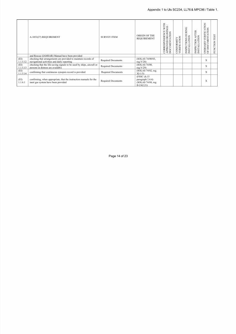
8/12/2019 loadline interpretion
http://slidepdf.com/reader/full/loadline-interpretion 125/137
Appendix 1 to UIs SC234, LL76 & MPC96 / Table 1.
Page 14 of 23
A.1053(27) REQUIREMENT SURVEY ITEMORIGIN OF THE
REQUIREMENT
C O R R E S P O N D E N C E W I T H
A P P R O V E D D R A W I N G S /
D O C U M E N T A T I O N
C O N F O R M I T Y
V E R I F I C A T I O N
I N S P E C T I O N S D U R I N G
I N S T A L L A T I O N
I N S P E C T I O N A F T E R
I N S T A L L A T I O N
O N B O A R D V E R I F I C A T I O N
O F D O C U M E N T A T I O N
F U N C T I O N T E S T
and Rescue (IAMSAR) Manual have been provided
(EI)1.1.5.12
checking that arrangements are provided to maintain records ofnavigational activities and daily reporting
Required Documents (SOLAS 74/00/03,reg.V/28)
X
(EI)
1.1.5.13
checking that the life-saving signals to be used by ships, aircraft or
persons in distress are availableRequired Documents
(SOLAS 74/00,
reg.V/29)X
(EI)
1.1.5.14confirming that continuous synopsis record is provided Required Documents
(SOLAS 74/02, reg.
XI-1/5)X
(EI)
1.1.6.1
confirming, when appropriate, that the instruction manuals for the
inert gas system have been providedRequired Documents
(FSSC ch.15
paragraph 2.4.4)
(SOLAS 74/88, reg.
II-2/62.21)
X

8/12/2019 loadline interpretion
http://slidepdf.com/reader/full/loadline-interpretion 126/137
Appendix 1 to UIs SC234, LL76& MPC96 / Table 2.
Page 15 of 23
Table 2. Load Line
A.1053(27) REQUIREMENT SURVEY ITEMORIGIN OF THE
REQUIREMENT
C O R
R E S P O N S E N C E W I T H
A P P R O V E D D R A W I N G S /
D O C U M E N T A T I O N
C O N F O R M I T Y V E R I F I C A T I O N
S U R V E Y D U R I N G
C
O N S T R U C T I O N O R
I N S T A L L A T I O N
T I G H T N E S S T E S T
S U R V E Y A F T E R
C
O N S T R U C T I O N O R
I N S T A L L A T I O N
F U N C T I O N T E S T
O N B O A R D V E R I F I A T I O N
O F
D O C U M E N T A T I O N
(LI)
1.1.1
For the load line the examination of plans and
designs should consist of:
(LI)
1.1.1.2
examining the intact stability, and, where
applicable, the damaged stability information and
the loading and ballasting information that is to be
supplied to the master, and, where not dispensed
by the Administration, inclining experimental data
intact stability, and, where applicable,
the damaged stability information and
the loading and ballasting information
(LLC 66/88/08 regs.1 and 10;
IS Code chs.1, 2 and 3)
X X
(LI)
1.1.2
For the load line the survey during construction
and after installation should consist of:
(LI)
1.1.2.2
confirming that the deck line and load line mark
are properly positioned
Positioning of Deck Line and Load
Line Mark(LLC 66/88 regs.4 to 9) X X
(LI)
1.1.2.3
witnessing the inclining experiment or lightweight
surveyInclining Experiment (LLC 66/88/03 reg.10) X X
(LI)
1.1.2.4
examining the superstructure end bulkheads and
the openings therein
Superstructure End Bulkheads(LLC 66/88 regs.11 and 12)
Superstructure Openings X X X X
(LI)
1.1.2.5
examining the means of securing the weather
tightness of cargo hatchways, other hatchways and
other openings on the freeboard and superstructure
decks
Freeboard Deck - Means of Securing
the weather tightness of Cargo
Hatchways
(LLC 66/88 regs. 13 to 18)
X X X X
Freeboard Deck - Means of Securing
the weather tightness of Other
Hatchways
X X X
Freeboard Deck - Means of Securing
the weather tightness of Other
Openings
X X X
Superstructure Deck - Means of
Securing the weather tightness of
Cargo Hatchways
X X X X
Superstructure Deck - Means of X X X
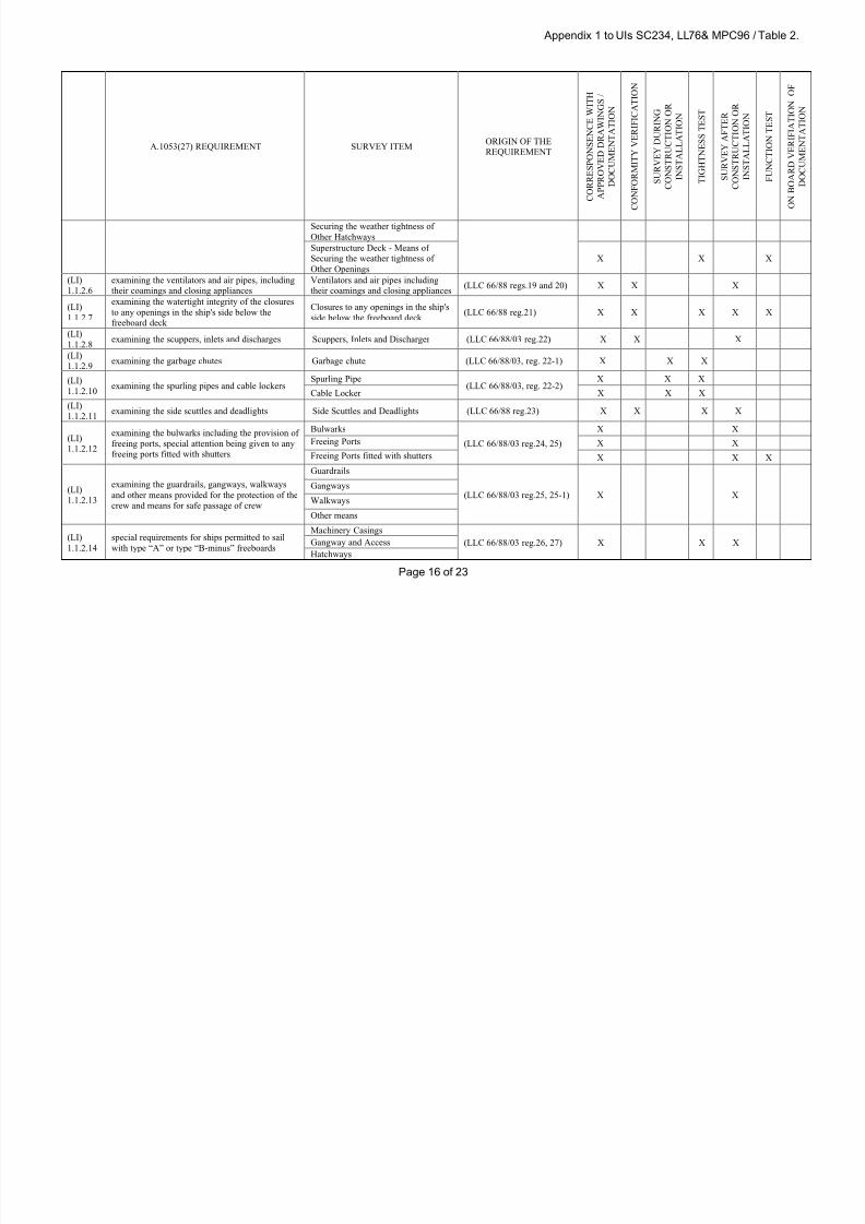
8/12/2019 loadline interpretion
http://slidepdf.com/reader/full/loadline-interpretion 127/137
Appendix 1 to UIs SC234, LL76& MPC96 / Table 2.
Page 16 of 23
A.1053(27) REQUIREMENT SURVEY ITEMORIGIN OF THE
REQUIREMENT
C O R R E S P O N S E N C E W I T H
A P P R O V E D D R A W I N G S /
D O C U M E N T A T I O N
C O N F O R M I T Y V E R I F I C A T I O N
S U R V E Y D U R I N G
C O N S T R U C T I O N O R
I N S T A L L A T I O N
T I G H T N E S S T E S T
S U R V E Y A F T E R
C O N S T R U C T I O N O R
I N S T A L L A T I O N
F U N C T I O N T E S T
O N B O A R D V E R I F I A T I O N
O F
D O C U M E N T A T I O N
Securing the weather tightness of
Other Hatchways
Superstructure Deck - Means of
Securing the weather tightness of
Other Openings
X X X
(LI)
1.1.2.6
examining the ventilators and air pipes, including
their coamings and closing appliances
Ventilators and air pipes including
their coamings and closing appliances(LLC 66/88 regs.19 and 20) X X X
(LI)
1.1.2.7
examining the watertight integrity of the closures
to any openings in the ship's side below the
freeboard deck
Closures to any openings in the ship's
side below the freeboard deck(LLC 66/88 reg.21) X X X X X
(LI)
1.1.2.8examining the scuppers, inlets and discharges Scuppers, Inlets and Discharger (LLC 66/88/03 reg.22) X X X
(LI)
1.1.2.9examining the garbage chutes Garbage chute (LLC 66/88/03, reg. 22-1) X X X
(LI)
1.1.2.10examining the spurling pipes and cable lockers
Spurling Pipe(LLC 66/88/03, reg. 22-2)
X X X
Cable Locker X X X
(LI)
1.1.2.11examining the side scuttles and deadlights Side Scuttles and Deadlights (LLC 66/88 reg.23) X X X X
(LI)
1.1.2.12
examining the bulwarks including the provision of
freeing ports, special attention being given to any
freeing ports fitted with shutters
Bulwarks
(LLC 66/88/03 reg.24, 25)
X X
Freeing Ports X X
Freeing Ports fitted with shutters X X X
(LI)
1.1.2.13
examining the guardrails, gangways, walkways
and other means provided for the protection of the
crew and means for safe passage of crew
Guardrails
(LLC 66/88/03 reg.25, 25-1) X XGangways
Walkways
Other means
(LI)
1.1.2.14
special requirements for ships permitted to sail
with type “A” or type “B-minus” freeboards
Machinery Casings
(LLC 66/88/03 reg.26, 27) X X XGangway and Access
Hatchways

8/12/2019 loadline interpretion
http://slidepdf.com/reader/full/loadline-interpretion 128/137
Appendix 1 to UIs SC234, LL76& MPC96 / Table 2.
Page 17 of 23
A.1053(27) REQUIREMENT SURVEY ITEMORIGIN OF THE
REQUIREMENT
C O R R E S P O N S E N C E W I T H
A P P R O V E D D R A W I N G S /
D O C U M E N T A T I O N
C O N F O R M I T Y V E R I F I C A T I O N
S U R V E Y D U R I N G
C O N S T R U C T I O N O R
I N S T A L L A T I O N
T I G H T N E S S T E S T
S U R V E Y A F T E R
C O N S T R U C T I O N O R
I N S T A L L A T I O N
F U N C T I O N T E S T
O N B O A R D V E R I F I A T I O N
O F
D O C U M E N T A T I O N
Freeing arrangements
(LI)
1.1.2.15
checking, when applicable, of the fittings and
appliances for timber deck cargoes
Uprights
(LLC 66/88 regs.42 to 45)
X X
Lashings X X
Stability X X
Protection of Crew X X
(LI)
1.1.3.1
checking that the loading and ballasting
information has been supplied to the masterLoading and Stability Manual (LLC 66/88 reg.10) X X
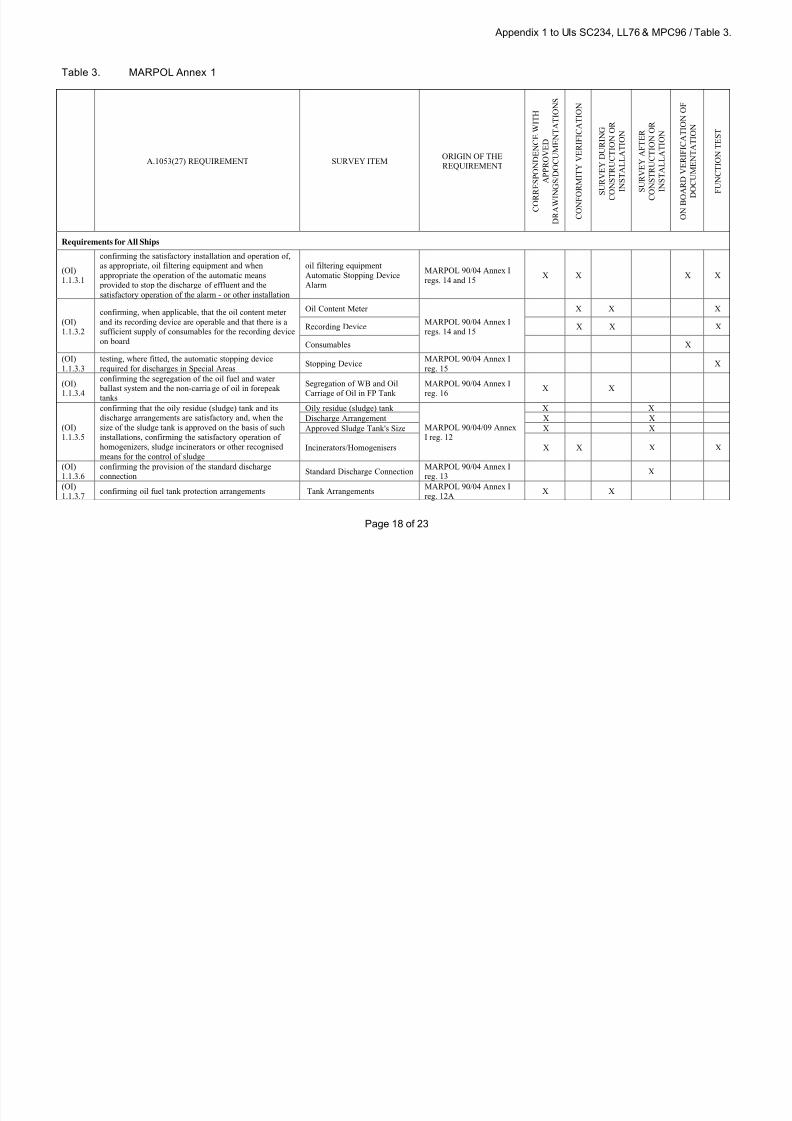
8/12/2019 loadline interpretion
http://slidepdf.com/reader/full/loadline-interpretion 129/137
Appendix 1 to UIs SC234, LL76 & MPC96 / Table 3.
Page 18 of 23
Table 3. MARPOL Annex 1
A.1053(27) REQUIREMENT SURVEY ITEMORIGIN OF THE
REQUIREMENT
C O R R E S P O N D E N C E W I T H
A P P R O V E D
D R A W I N
G S / D O C U M E N T A T I O N S
C O N F O
R M I T Y V E R I F I C A T I O N
S U R V E Y D U R I N G
C O N S T R U C T I O N O R
I N S T A L L A T I O N
S U R V E Y A F T E R
C O N S T R U C T I O N O R
I N S T A L L A T I O N
O N B O A R D V E R I F I C A T I O N O F
D
O C U M E N T A T I O N
F U N C T I O N T E S T
Requirements for All Ships
(OI)
1.1.3.1
confirming the satisfactory installation and operation of,
as appropriate, oil filtering equipment and when
appropriate the operation of the automatic means
provided to stop the discharge of effluent and the
satisfactory operation of the alarm - or other installation
oil filtering equipment
Automatic Stopping Device
Alarm
MARPOL 90/04 Annex I
regs. 14 and 15X X X X
(OI)
1.1.3.2
confirming, when applicable, that the oil content meter
and its recording device are operable and that there is a
sufficient supply of consumables for the recording device
on board
Oil Content Meter
MARPOL 90/04 Annex I
regs. 14 and 15
X X X
Recording Device X X X
Consumables X
(OI)
1.1.3.3
testing, where fitted, the automatic stopping device
required for discharges in Special AreasStopping Device
MARPOL 90/04 Annex I
reg. 15X
(OI)
1.1.3.4
confirming the segregation of the oil fuel and water
ballast system and the non-carriage of oil in forepeaktanks
Segregation of WB and Oil
Carriage of Oil in FP Tank
MARPOL 90/04 Annex I
reg. 16 X X
(OI)
1.1.3.5
confirming that the oily residue (sludge) tank and its
discharge arrangements are satisfactory and, when the
size of the sludge tank is approved on the basis of such
installations, confirming the satisfactory operation of
homogenizers, sludge incinerators or other recognised
means for the control of sludge
Oily residue (sludge) tank
MARPOL 90/04/09 Annex
I reg. 12
X X
Discharge Arrangement X X
Approved Sludge Tank's Size X X
Incinerators/Homogenisers X X X X
(OI)
1.1.3.6
confirming the provision of the standard discharge
connectionStandard Discharge Connection
MARPOL 90/04 Annex I
reg. 13X
(OI)
1.1.3.7confirming oil fuel tank protection arrangements Tank Arrangements
MARPOL 90/04 Annex I
reg. 12AX X
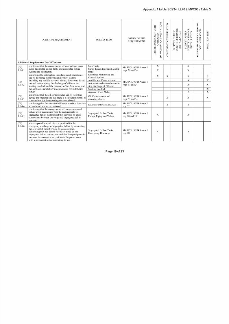
8/12/2019 loadline interpretion
http://slidepdf.com/reader/full/loadline-interpretion 130/137
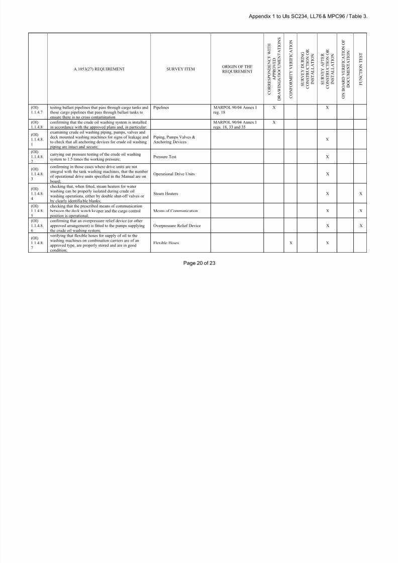
8/12/2019 loadline interpretion
http://slidepdf.com/reader/full/loadline-interpretion 131/137
Appendix 1 to UIs SC234, LL76 & MPC96 / Table 3.
Page 20 of 23
A.1053(27) REQUIREMENT SURVEY ITEMORIGIN OF THE
REQUIREMENT
C O R R E S P O N D E N C E W I T H
A P P R O V E D
D R A W I N G S / D O C U M E N T A T I O N S
C
O N F O R M I T Y V E R I F I C A T I O N
S U R V E Y D U R I N G
C O N S T R U C T I O N O R
I N S T A L L A T I O N
S U R V E Y A F T E R
C O N S T R U C T I O N O R
I N S T A L L A T I O N
O
N B O A R D V E R I F I C A T I O N O F
D O C U M E N T A T I O N
F U N C T I O N T E S T
(OI)
1.1.4.7
testing ballast pipelines that pass through cargo tanks and
those cargo pipelines that pass through ballast tanks to
ensure there is no cross contamination
Pipelines MARPOL 90/04 Annex I
reg. 18
X X
(OI)
1.1.4.8
confirming that the crude oil washing system is installed
in accordance with the approved plans and, in particular:
MARPOL 90/04 Annex I
regs. 18, 33 and 35
X
(OI)
1.1.4.8.
1
examining crude oil washing piping, pumps, valves and
deck mounted washing machines for signs of leakage and
to check that all anchoring devices for crude oil washing
piping are intact and secure;
Piping, Pumps Valves &
Anchoring DevicesX
(OI)
1.1.4.8.
2
carrying out pressure testing of the crude oil washing
system to 1.5 times the working pressure;Pressure Test X
(OI)
1.1.4.8.
3
confirming in those cases where drive units are not
integral with the tank washing machines, that the number
of operational drive units specified in the Manual are on
board;
Operational Drive Units X
(OI)
1.1.4.8.
4
checking that, when fitted, steam heaters for water
washing can be properly isolated during crude oil
washing operations, either by double shut-off valves or by clearly identifiable blanks;
Steam Heaters X X
(OI)
1.1.4.8.
5
checking that the prescribed means of communication
between the deck watch keeper and the cargo control
position is operational;
Means of Communication X X
(OI)
1.1.4.8.
6
confirming that an overpressure relief device (or other
approved arrangement) is fitted to the pumps supplying
the crude oil washing system;
Overpressure Relief Device X X
(OI)
1.1.4.8.
7
verifying that flexible hoses for supply of oil to the
washing machines on combination carriers are of an
approved type, are properly stored and are in good
condition;
Flexible Hoses X X

8/12/2019 loadline interpretion
http://slidepdf.com/reader/full/loadline-interpretion 132/137
Appendix 1 to UIs SC234, LL76 & MPC96 / Table 3.
Page 21 of 23
A.1053(27) REQUIREMENT SURVEY ITEMORIGIN OF THE
REQUIREMENT
C O R R E S P O N D E N C E W I T H
A P P R O V E D
D R A W I N G S / D O C U M E N T A T I O N S
C
O N F O R M I T Y V E R I F I C A T I O N
S U R V E Y D U R I N G
C O N S T R U C T I O N O R
I N S T A L L A T I O N
S U R V E Y A F T E R
C O N S T R U C T I O N O R
I N S T A L L A T I O N
O
N B O A R D V E R I F I C A T I O N O F
D O C U M E N T A T I O N
F U N C T I O N T E S T
(OI)
1.1.4.9
verifying the effectiveness of the crude oil washing
system and, in particular:
COW-Crude Oil Washing:
Effectiveness
MARPOL 90/04 Annex I
reg. 33
(OI)
1.1.4.9.
1
checking that the crude oil washing machines are
operable and to observe the proper operation of the
washing machines by means of the movement indicators
and/or sound patterns or other approved methods;
X X
(OI)
1.1.4.9.
2
checking the effectiveness of the stripping system in
appropriate cargo tanks by observing the monitoring
equipment and by hand-dipping or other approved means;
X
(OI)
1.1.4.9.
3
verifying by internal tank inspection after crude oil
washing that the installation and operational procedures
laid down in the Operations and Equipment Manual are
satisfactory;
X
(OI)
1.1.4.10
confirming that, where there is a crude oil washing
system, an inert gas system has been installed and tested
in accordance with the requirements of SOLAS
74/88/2000 (see (EI) 1.1.4.2 in Annex 1);
COW-Crude Oil Washing:
GeneralX X X
(OI)
1.1.4.11
confirming, as appropriate, that the arrangements for the
prevention of oil pollution in the event of collision orstranding are in accordance with the approved plans
Pollution due to Collision or
Stranding
MARPOL 90/04 Annex I
regs. 19 to 22 X X
(OI)
1.1.4.12
confirming that the piping systems associated with the
discharge of dirty ballast water or oil-contaminated water
are satisfactory
Pumping, Piping and DischargeMARPOL 90/04 Annex I
reg. 30X X
(OI)
1.1.4.13
confirming that the observation and discharge control
positions for visually observing the discharge of oil-
contaminated water, including the testing of the
communication system between the two positions are
satisfactory
Observation and Discharge
Control
MARPOL 90/04 Annex I
reg. 30X X

8/12/2019 loadline interpretion
http://slidepdf.com/reader/full/loadline-interpretion 133/137
Appendix 1 to UIs SC234, LL76 & MPC96 / Table 3.
Page 22 of 23
A.1053(27) REQUIREMENT SURVEY ITEMORIGIN OF THE
REQUIREMENT
C O R R E S P O N D E N C E W I T H
A P P R O V E D
D R A W I N G S / D O C U M E N T A T I O N S
C
O N F O R M I T Y V E R I F I C A T I O N
S U R V E Y D U R I N G
C O N S T R U C T I O N O R
I N S T A L L A T I O N
S U R V E Y A F T E R
C O N S T R U C T I O N O R
I N S T A L L A T I O N
O
N B O A R D V E R I F I C A T I O N O F
D O C U M E N T A T I O N
F U N C T I O N T E S T
(OI)
1.1.4.14
confirming that the means of draining cargo pumps and
cargo lines, including the provision of a stripping device
and the connections for pumping to the slop or cargo
tanks or ashore are satisfactory
Means of Draining and
Stripping MARPOL 90/04 Annex I
reg. 30
X X
means for pumping ashore /
slop / cargo tanksX X
(OI)
1.1.4.15
confirming that closing devices installed in the cargo
transfer system and cargo piping, as appropriate, are
satisfactory
Closing arrangementsMARPOL 90/04 Annex I
regs. 23 & 26X
(OI)
1.1.4.16
confirming that the subdivision and stability
arrangements, in addition to the provision of (OI)
1.1.4.15, to prevent progressive flooding are satisfactory
Stability Manual
Tank Arrangement
MARPOL 90/04 Annex I
regs. 23 & 26X X X
(OI)
1.1.4.17
confirming the arrangements for cargo pump-room
bottom protection (double bot tom where required)Tank Arrangements
MARPOL 90/04 Annex I
reg. 22X X
Requirements for All Ships
(OI)
1.1.5.1
confirming that certificates for type approval for the oil
filtering equipment and oil content meters are availableType Approval Certificates
MARPOL 90/04 Annex I
reg. 14X X
(OI)
1.1.5.2
confirming that the Oil Record Book (Part I) has been
providedOil Record Book
MARPOL 90/04 Annex I
reg. 17X
(OI)
1.1.5.3
confirming that the shipboard oil pollution emergency plan or, in the case of a chemical/product tanker, a
shipboard marine pollution emergency plan has been
provided
SOPEP/SMPEPMARPOL 90/04 Annex I
reg. 37X X
(OI)
1.1.5.4
confirming, as appropriate, that the Operating and
Maintenance manuals for the 15ppm bilge separator and
15ppm bilge alarm are available
Operations Manual X
Additional Requirements for Oil Tankers
(OI)
1.1.6.1
confirming that, if applicable, a Ship to Ship (STS)
operations Plan approved by the Administration has been
provided
STS operations plan
MARPOL Annex I
Reg.41X X
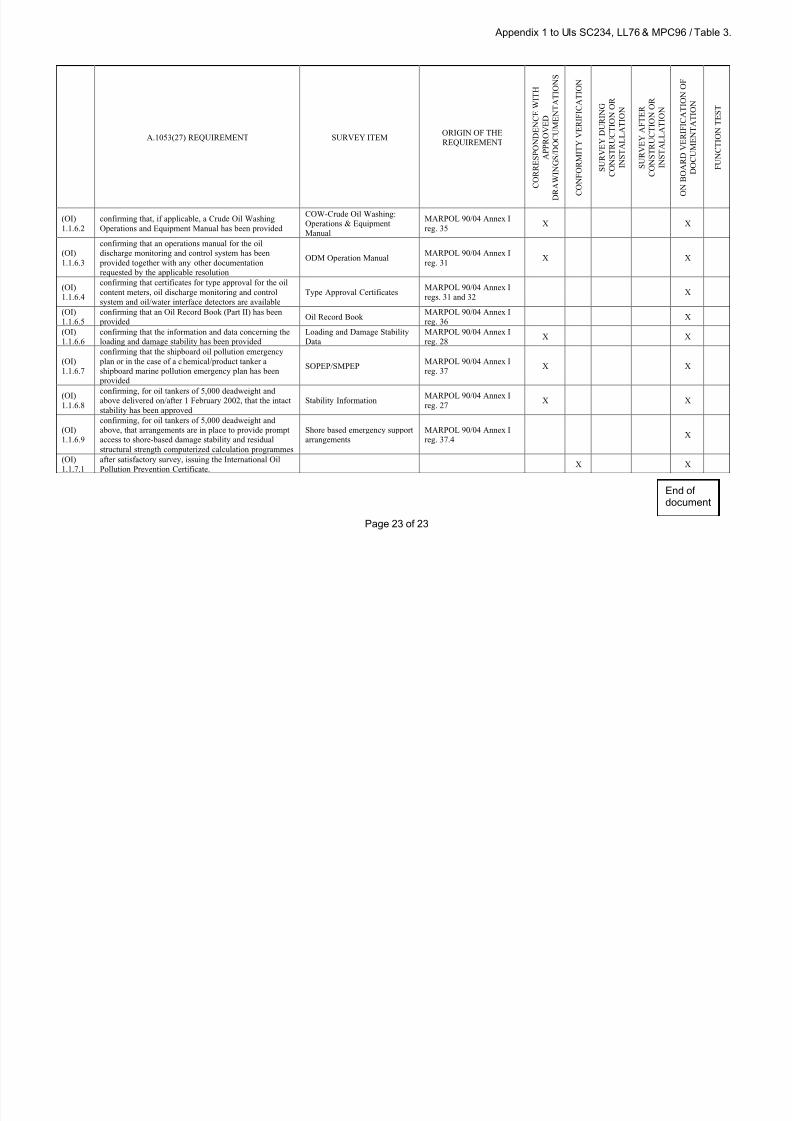
8/12/2019 loadline interpretion
http://slidepdf.com/reader/full/loadline-interpretion 134/137
Appendix 1 to UIs SC234, LL76 & MPC96 / Table 3.
Page 23 of 23
A.1053(27) REQUIREMENT SURVEY ITEMORIGIN OF THE
REQUIREMENT
C O R R E S P O N D E N C E W I T H
A P P R O V E D
D R A W I N G S / D O C U M E N T A T I O N S
C
O N F O R M I T Y V E R I F I C A T I O N
S U R V E Y D U R I N G
C O N S T R U C T I O N O R
I N S T A L L A T I O N
S U R V E Y A F T E R
C O N S T R U C T I O N O R
I N S T A L L A T I O N
O
N B O A R D V E R I F I C A T I O N O F
D O C U M E N T A T I O N
F U N C T I O N T E S T
(OI)
1.1.6.2
confirming that, if applicable, a Crude Oil Washing
Operations and Equipment Manual has been provided
COW-Crude Oil Washing:
Operations & Equipment
Manual
MARPOL 90/04 Annex I
reg. 35X X
(OI)
1.1.6.3
confirming that an operations manual for the oil
discharge monitoring and control system has been
provided together with any other documentation
requested by the applicable resolution
ODM Operation ManualMARPOL 90/04 Annex I
reg. 31X X
(OI)
1.1.6.4
confirming that certificates for type approval for the oil
content meters, oil discharge monitoring and control
system and oil/water interface detectors are available
Type Approval CertificatesMARPOL 90/04 Annex I
regs. 31 and 32X
(OI)
1.1.6.5
confirming that an Oil Record Book (Part II) has been
providedOil Record Book
MARPOL 90/04 Annex I
reg. 36X
(OI)
1.1.6.6
confirming that the information and data concerning the
loading and damage stability has been provided
Loading and Damage Stability
Data
MARPOL 90/04 Annex I
reg. 28X X
(OI)
1.1.6.7
confirming that the shipboard oil pollution emergency
plan or in the case of a chemical/product tanker a
shipboard marine pollution emergency plan has been
provided
SOPEP/SMPEPMARPOL 90/04 Annex I
reg. 37X X
(OI)
1.1.6.8
confirming, for oil tankers of 5,000 deadweight andabove delivered on/after 1 February 2002, that the intact
stability has been approved
Stability InformationMARPOL 90/04 Annex I
reg. 27X X
(OI)
1.1.6.9
confirming, for oil tankers of 5,000 deadweight and
above, that arrangements are in place to provide prompt
access to shore-based damage stability and residual
structural strength computerized calculation programmes
Shore based emergency support
arrangements
MARPOL 90/04 Annex I
reg. 37.4X
(OI)
1.1.7.1
after satisfactory survey, issuing the International Oil
Pollution Prevention Certificate.X X
End ofdocument

8/12/2019 loadline interpretion
http://slidepdf.com/reader/full/loadline-interpretion 135/137
LL77
Page 1 of 2 IACS Int. 2011
LL77(cont)
Application of Load Line Requirements toConversions of Single-hull Oil Tankers toDouble-hull Oil Tankers or Bulk Carriers
Article 10 - Repairs, alterations and modifications
(1) A ship which undergoes repairs, alterations, modifications and outfitting related theretoshall continue to comply with at least the requirements previously applicable to the ship. An
existing ship in such a case shall not, as a rule, comply to a lesser extent with therequirements for a new ship than it did before.
(2) Repairs, alterations and modifications of a major character and outfitting related theretoshould meet the requirements for a new ship in so far as the administration deems
reasonable and practicable.
Interpretation
1 For single-hull oil tankers converted to double-hull oil tankers:
1.1 The ship should meet the requirements of the regulations contained in chapter III(Freeboards) of Annex I of the Load Line Convention in effect at the date of conversion. Incases where there are no changes to the parameters which result in a change of theminimum freeboard*1, and where there is no decrease in magnitude of freeboard assigned
after conversion, using the Convention previously applicable to the ship in determining anychange or decrease as mentioned above, the converted ship should continue to comply with
at least the requirements previously applicable to the ship.
1.2 Any structure and/or equipment such as doors, hatches, and cable lockers, etc., whichis newly added, replaced, or modified is to comply with the requirements of the regulationscontained in chapter II (Conditions of assignment of freeboard) of Annex I of the Convention
in effect at the date of conversion.
2 For single-hull oil tankers converted to bulk carriers:
2.1 Any such conversion should be regarded as a modification of a major character and theship should meet all the requirements of the regulations annexed to the Convention (including
regulation 39) in effect at the date of conversion; and
2.2 Notwithstanding the above, the requirements of the regulations contained in chapter II(Conditions of assignment of freeboard) of Annex I of the Convention in effect at the date of
conversion, should be applied only to the structure and/or equipment, which is newly added,replaced, or modified.
Note
This UI is to be uniformly implemented by IACS Societies to conversions which occur (asdefined in paragraph 3) on or after 1 January 2013.
LL77(Nov2011)
LL77(Dec
2011)
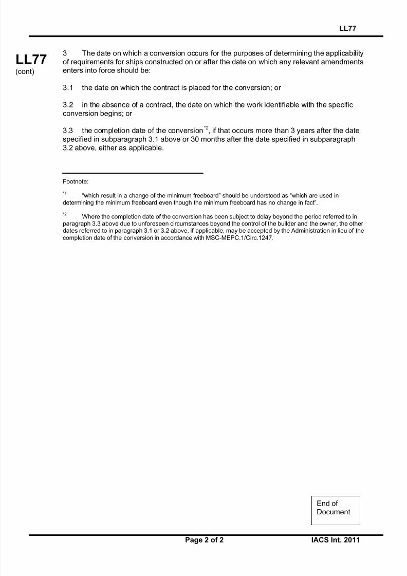
8/12/2019 loadline interpretion
http://slidepdf.com/reader/full/loadline-interpretion 136/137
LL77
Page 2 of 2 IACS Int. 2011
LL77(cont)
3 The date on which a conversion occurs for the purposes of determining the applicabilityof requirements for ships constructed on or after the date on which any relevant amendmentsenters into force should be:
3.1 the date on which the contract is placed for the conversion; or
3.2 in the absence of a contract, the date on which the work identifiable with the specificconversion begins; or
3.3 the completion date of the conversion*2, if that occurs more than 3 years after the date
specified in subparagraph 3.1 above or 30 months after the date specified in subparagraph3.2 above, either as applicable.
Footnote:
*1“which result in a change of the minimum freeboard” should be understood as “which are used in
determining the minimum freeboard even though the minimum freeboard has no change in fact”.
*2Where the completion date of the conversion has been subject to delay beyond the period referred to in
paragraph 3.3 above due to unforeseen circumstances beyond the control of the builder and the owner, the other dates referred to in paragraph 3.1 or 3.2 above, if applicable, may be accepted by the Administration in lieu of the
completion date of the conversion in accordance with MSC-MEPC.1/Circ.1247.
End of Document

8/12/2019 loadline interpretion
http://slidepdf.com/reader/full/loadline-interpretion 137/137
MPC104, LL78 and HSC9
SC260(cont)
MPC104(cont)
LL78(cont)
MLC
1(cont)
HSC9(cont)
Keel Laying Date for Fibre-Reinforced Plastic(FRP) Craft
Interpretation
For the purposes of the application of the IMO Conventions and Codes (PerformanceStandards, Technical Standards, Resolutions and Circulars) for Fibre-Reinforced Plastic(FRP) Craft, the term “the keels of which are laid or which are at a similar stage of construction” should be interpreted as the date that the first structural reinforcement of the
complete thickness of the approved hull laminate schedule is laid either in or on the mould.
MPC104(Mar 2013)
(Corr.1Jan 2014)
LL78(Mar 2013)(Corr.1Jan 2014)
HSC
9(Mar 2013)
(Corr.1Jan 2014)