biogas plant construction manualbuild-a-biogas-plant.com/pdf/skgconstrution manual2013.pdf · a...
TRANSCRIPT
1
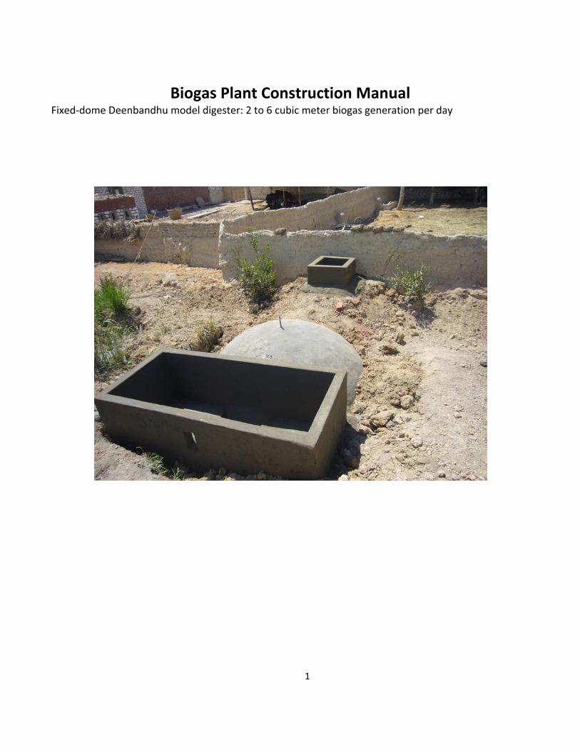
Biogas Plant Construction Manual Fixed‐dome Deenbandhu model digester: 2 to 6 cubic meter biogas generation per day

2
SKG Sangha, Egypt – January 2013
Forward
The Biomass for Sustainable Rural Development project is a joint programme between the
Egyptian Environmental Affairs Agency (EEAA), Ministry of State for Environmental Affairs,
Global Environmental Facility (GEF) and the United Nations Development Programme (UNDP)
The project is to facilitate and accelerate the market development for new bio‐energy
technologies in Egypt to remove certain technological and capacity barriers in development of
biogas project for Egypt. SKG Sangha (SKGS) has been selected to install 100 domestic biogas
plants in two governorates, Fayoum and Assiyut in the households selected by the Biomass
Project. SKGS will install, monitor and maintain units for a period of ten months. During the
course of plants installation train local masons, selected by the Biomass Project on
construction, train supervisory staff, again selected by the Biomass Project on design
parameters, monitoring and maintenance. The design of the plant will be a fixed dome on the
lines of Deenbandhu model specifically designed by SKGS suitable for Egyptian conditions. As
the mean temperature of the Egypt is about 21 degrees Celsius the plant has been designed
with 50 days hydraulic retention time (HRT). The project will be implemented by SKGS and
monitored by the Biomass Project. A primary list of probable beneficiaries will be made by the
local body of the governorate and will be scrutinized by the biomass project and will be sent to
SKGS for final selection of beneficiaries. The selected beneficiaries will be provided with a
suitable size biogas plant based on the cattle population and number of members in the
household.
Kiran Kumar K Secretary SKG Sangha [email protected] www.skgsangha.org
3
Table of Contents
1. Introduction .................................................................................................................. 5 2. Selection of Construction Materials.............................................................................. 6
2.1 Cement …………………………………………………………………………………………………. 6 2.2 Sand ……………………………………………………………………………………………………… 6
2.3 Stone Aggregates ………………………………………………………………………….. 7
2.4 A pipe to connect the digester and the inlet tank …………………………. 8
2.5 Brackets welded galvanized iron pipe …………………………………………….. 8
2.6 Valve to control the gas flow ………………………………………………………….. 8 2.7 Bricks ……………………………………………………………………………………….. 8 2.8 High Density Poly Ethylene Pipe (HDPE) pipe ……………………………………….. 9
2.9 Rubber Hose ………………………………………………………………………………. 9
2.10 Brass Nipple ……………………………………………….……………………. 9 2.11 Biogas Burner ……………………………………………………………………….………….. 9 2.12 Water ………………………………………………………………………………………………. 9
3. Determining Plant Size ……………………………………………………………………………………………. 10 4. Construction Site Selection.......................................................................................... 10 5. Plan layout for excavation of pit ................................................................................. 11 6. Excavation of pit for plant installation ........................................................................ 11 7. Casting the bed concrete ………………………………………………………………………………………… 13 8. Construction of centre pillar ……………………………………………………………………………………. 13 9. Guide pole ………………………………………………………………………………………………………………. 14 10. Fixing first layer of bricks ………………………………………………………………………………………. 14 11. Starting construction of the digester …………………………………………………………………….. 15 12. Placing of inlet pipe ………………………………………………………………………………………………. 15 13. Plastering the outside of the partly constructed digester ……………………………………… 16 14. Laying of brick layer as top of the digester slurry flow door ………………………………….. 16 15. Pouring of cement water to seal any pours in the constructed digester ……………….. 17 16. Excavation of earth for construction of displacement chamber …………………………….. 17 17. Laying of foundation for the displacement chamber ……………………………………………… 18
4
18. Fixing of GI nipple at the zenith of the digester …………………………………………………….. 18 19. Pouring of Cement water on top of the digester and plastering ……………………………. 19 20. Removal of “ARAVANA” fixed inside the digester …………………………………………………. 19 21. Plastering of digester inside portion …………………………………………………………………….. 19 22. Application of cement paste on the inside portion of the digester ……………………….. 19 23. Application of cement coat …………………………………………………………………………………… 19 24. Construction of displacement tank ………………………………………………………………………. 20 25. Casting of concrete slabs / plates meant for covering the displacement tank ………. 20 26. Construction of inlet tank …………………………………………………………………………………….. 20 27. Curing of civil works with water …………………………………………………………………………… 20 28. Compacting of the civil works with soil ………………………………………………………………… 21 29. Digging of pit to collect spent slurry …………………………………………………………………….. 21 30. Initial feeding of plant ………………………………………………………………………………………….. 21 31. Required physio‐ chemical conditions for optimum production of biogas ……………. 21 32. Construction measurements of the biogas plant ………………………………………………….. 22 33. Design of the biogas plant ……………………………………………………………………………………. 23 34. Material requirement for the biogas plant …………………………………………………………… 24 35. Deviations from the design ………………………………………………………………………………….. 25 Attachment: Operation and Maintenance of Biogas Plant
Tables Table: 31. Phsio – Chemical conditions for optimum production of biogas ……………….. 20 Table: 32. Construction Measurements of biogas plant …………………………………………….. 21 Table: 34. Required material for biogas plant installation ………………………………………….. 23 Figures Figure: 5.1 Pit Layouts ...………………………………………………………………………………………...... 10 Figure: 6.1 Excavation of a pit for plant installation using machine……………………………. 11 Figure: 6.2 A trimmed pit ready for bed concrete ……………………………………………………… Figure: 7.1 Maintain level of bed concrete all the round using plastic tube filled
with water ……………………………………………………………………………………………….. 12 Figure: 8.1 Construction of centre pillar …………………………………………………………………….. 12 Figure: 9.1 Guide poll …………………………………………………………………………………………………. 13 Figure: 9.2 Guide poll …………………………………………………………………………………………………. 13 Figure: 10.1 Placing first layer of bricks……………............................................................. 13 Figure: 10.2 Spacing first layer of bricks ……………………………………………………………………… 13 Figure: 11.1 Starting construction of the digester ………………………………………………………. 14 Figure: 12.1 Placing of inlet pipe …………………………………………………………………………………. 14 Figure: 12.2 Placing of inlet pipe …………………………………………………………………………………. 14 Figure: 12.4 Fixing of inlet pipe …………………………………………………………………………………… 15 Figure: 12.4 Fixing of inlet pipe lower than the slurry flow gate height ………………………. 15 Figure: 14.1 Support plank for box tank ceiling layer ………………………………………………….. 16
5
Figure: 16.1 Sand filling to raise the area to required height ..…………………………………….. 17 Figure: 17.1 First layer of bricks …………………………………………………………………………………… 17 Figure: 17.2 Bricks have to be fixed at required measurements ………………………………….. 17 Figure: 33.1 : Plan and sectional diagram of the biogas plant ………………………………………. 22
1. Introduction
Biogas plant is an anaerobic civil construction. All types of soft wastes can be fed into this plant. Different types of bacteria will decompose this feed material and generate biogas. Biogas is a combination of few gases like Methane, carbon dioxide and Hydrogen sulfide. Predominantly biogas contains about 65% methane and about 35% carbon dioxide with traces of other gases. The treated waste which comes out of biogas plant is rich with useful bacteria and also major and micro nutrients. Biogas plants are preferred throughout the world as an alternative source of energy supply and to create well fermented slurry to be used as liquid / solid manure in the agricultural soils and also to create sanitation. So far millions of biogas plants have been installed mainly to provide sustainable energy to rural households and overall improvement of human health and the environment. China and India are leaders in the line. The biogas plants are preferred as an alternative to burning dried animal dung cakes, fuel wood and in some cases LPG for daily cooking needs. Feed material for these biogas plants are human waste, meat and vegetable market wastes, food processing factories waste and almost all types of animal dung. Many factors like quantity of feedstock available on daily basis, type of waste, water availability, space availability, type of soil and ground water table level etc., have to be studied before installation of a biogas plant. Biogas plant especially the fixed dome model biogas plant installation requires well trained and experienced masons apart from quality material. Strict following of design measurements assures a long lasting biogas plant. Success or failure of biogas plants mainly depends upon how and by whom it has been installed and what type of quality material has been used apart from maintenance factors. There are many advantages of a fixed model biogas plant. It is under ground, saves space and somewhat immune to climatic conditions. There are no moving parts and hence lesser ware and tare. Almost no maintenance and it cost less than other designs.
6
The manual has been prepared by SKG Sangha ( www.skgsangha.org ) with its vast experience in construction of fixed model biogas plants (more than 105,000) for the use of managerial personnel trained on site and in project for further propagation of biogas plants in Egypt. This manual has been designed in such way that it can be used by a lay man, provided an experienced mason is available to construct a fixed model biogas plant. Step by step description along with figures and photos provides a clear understanding and methods for installation of the unit.
2. Selection of construction materials:
Material Availability: Almost all of the materials are available locally but finding them is a herculean
task. The following material is required for construction and use of fixed dome model biogas plant:
1. Cement 2. Sand
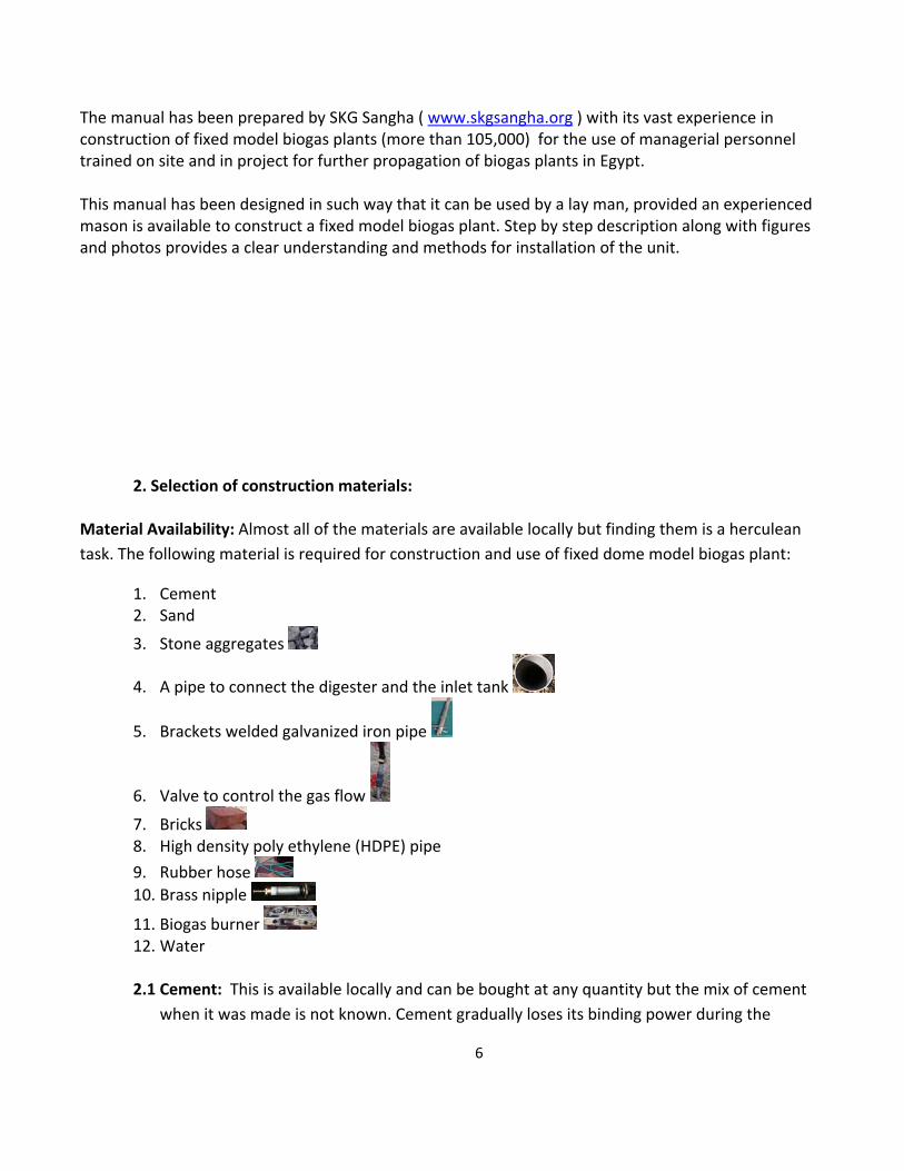
3. Stone aggregates
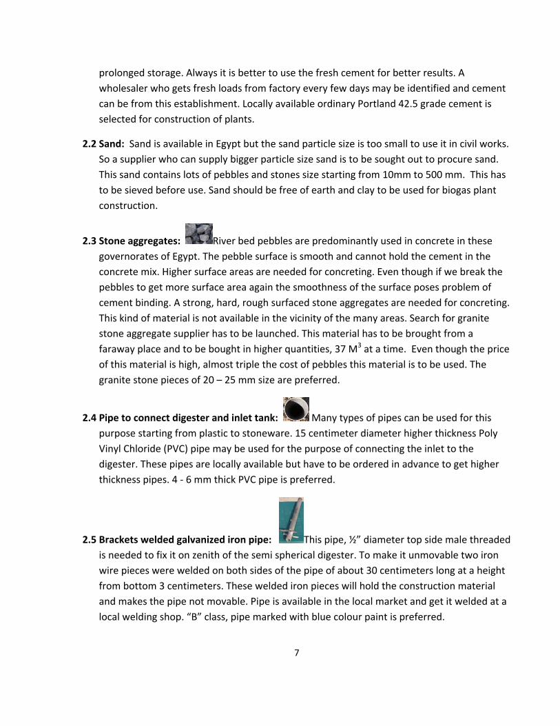
4. A pipe to connect the digester and the inlet tank
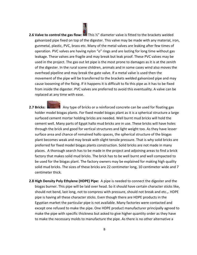
5. Brackets welded galvanized iron pipe
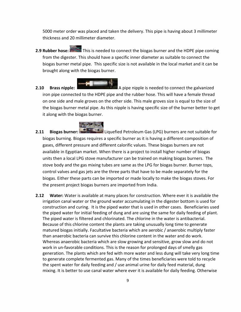
6. Valve to control the gas flow
7. Bricks 8. High density poly ethylene (HDPE) pipe
9. Rubber hose
10. Brass nipple
11. Biogas burner 12. Water
2.1 Cement: This is available locally and can be bought at any quantity but the mix of cement
when it was made is not known. Cement gradually loses its binding power during the
7
prolonged storage. Always it is better to use the fresh cement for better results. A
wholesaler who gets fresh loads from factory every few days may be identified and cement
can be from this establishment. Locally available ordinary Portland 42.5 grade cement is
selected for construction of plants.
2.2 Sand: Sand is available in Egypt but the sand particle size is too small to use it in civil works.
So a supplier who can supply bigger particle size sand is to be sought out to procure sand.
This sand contains lots of pebbles and stones size starting from 10mm to 500 mm. This has
to be sieved before use. Sand should be free of earth and clay to be used for biogas plant
construction.
2.3 Stone aggregates: River bed pebbles are predominantly used in concrete in these
governorates of Egypt. The pebble surface is smooth and cannot hold the cement in the
concrete mix. Higher surface areas are needed for concreting. Even though if we break the
pebbles to get more surface area again the smoothness of the surface poses problem of
cement binding. A strong, hard, rough surfaced stone aggregates are needed for concreting.
This kind of material is not available in the vicinity of the many areas. Search for granite
stone aggregate supplier has to be launched. This material has to be brought from a
faraway place and to be bought in higher quantities, 37 M3 at a time. Even though the price
of this material is high, almost triple the cost of pebbles this material is to be used. The
granite stone pieces of 20 – 25 mm size are preferred.
2.4 Pipe to connect digester and inlet tank: Many types of pipes can be used for this
purpose starting from plastic to stoneware. 15 centimeter diameter higher thickness Poly
Vinyl Chloride (PVC) pipe may be used for the purpose of connecting the inlet to the
digester. These pipes are locally available but have to be ordered in advance to get higher
thickness pipes. 4 ‐ 6 mm thick PVC pipe is preferred.
2.5 Brackets welded galvanized iron pipe: This pipe, ½” diameter top side male threaded
is needed to fix it on zenith of the semi spherical digester. To make it unmovable two iron
wire pieces were welded on both sides of the pipe of about 30 centimeters long at a height
from bottom 3 centimeters. These welded iron pieces will hold the construction material
and makes the pipe not movable. Pipe is available in the local market and get it welded at a
local welding shop. “B” class, pipe marked with blue colour paint is preferred.
8
2.6 Valve to control the gas flow: This ½” diameter valve is fitted to the brackets welded
galvanized pipe fixed on top of the digester. This valve may be made with any material, iron,
gunmetal, plastic, PVC, brass etc. Many of the metal valves are leaking after few times of
operation. PVC valves are having nylon “o” rings and are lasting for long time without gas
leakage. These valves are fragile and may break but leak proof. These PVC valves may be
used in the project. The gas out let pipe is the most prone to damages as it is at the zenith
of the digester. In the rural scene children, animals and in some cases wind also moves the
overhead pipeline and may break the gate valve. If a metal valve is used then the
movement of the pipe will be transferred to the brackets welded galvanized pipe and may
cause loosening of the fixing. If it happens it is difficult to fix this pipe as it has to be fixed
from inside the digester. PVC valves are preferred to avoid this eventuality. A valve can be
replaced at any time with ease.
2.7 Bricks: Any type of bricks or a reinforced concrete can be used for floating gas
holder model biogas plants. For fixed model biogas plant as it is a spherical structure a large
surfaced cement mortar holding bricks are needed. Well burnt mud bricks will hold the
cement well. Many parts of Egypt hallo mud bricks are in use. These bricks will have holes
through the brick and good for vertical structures and light weight too. As they have lesser
surface area and chance of remained hallo spaces, the spherical structure of the biogas
plant becomes weak and may break with slight tensile pressure. That is why solid bricks are
preferred for fixed model biogas plants construction. Solid bricks are not made in many
places. A thorough search has to be made in the project and adjoining areas to find a brick
factory that makes solid mud bricks. The brick has to be well burnt and well compacted to
be used for the biogas plant. The factory owners may be explained for making high quality
solid mud bricks. The sizes of these bricks are 22 centimeter long, 10 centimeter wide and 7
centimeter thick.
2.8 High Density Poly Ethylene (HDPE) Pipe: A pipe is needed to connect the digester and the
biogas burner. This pipe will be laid over head. So it should have certain character sticks like,
should not bend, last long, not to compress with pressure, should not break and etc.,. HDPE
pipe is having all these character sticks. Even though there are HDPE products in the
Egyptian market the particular pipe is not available. Many factories were contacted and
except one refused to make the pipe. One HDPE product manufacturer principally agreed to
make the pipe with specific thickness but asked to give higher quantity order as they have
to make the necessary molds to manufacture the pipe. As there is no other alternative a
9
5000 meter order was placed and taken the delivery. This pipe is having about 3 millimeter
thickness and 20 millimeter diameter.
2.9 Rubber hose: This is needed to connect the biogas burner and the HDPE pipe coming
from the digester. This should have a specific inner diameter as suitable to connect the
biogas burner metal pipe. This specific size is not available in the local market and it can be
brought along with the biogas burner.
2.10 Brass nipple: A pipe nipple is needed to connect the galvanized
iron pipe connected to the HDPE pipe and the rubber hose. This will have a female thread
on one side and male groves on the other side. This male groves size is equal to the size of
the biogas burner metal pipe. As this nipple is having specific size of the burner better to get
it along with the biogas burner.
2.11 Biogas burner: Liquefied Petroleum Gas (LPG) burners are not suitable for
biogas burning. Biogas requires a specific burner as it is having a different composition of
gases, different pressure and different calorific values. These biogas burners are not
available in Egyptian market. When there is a project to install higher number of biogas
units then a local LPG stove manufacturer can be trained on making biogas burners. The
stove body and the gas mixing tubes are same as the LPG for biogas burner. Burner tops,
control valves and gas jets are the three parts that have to be made separately for the
biogas. Either these parts can be imported or made locally to make the biogas stoves. For
the present project biogas burners are imported from India.
2.12 Water: Water is available at many places for construction. Where ever it is available the irrigation canal water or the ground water accumulating in the digester bottom is used for construction and curing. It is the piped water that is used in other cases. Beneficiaries used the piped water for initial feeding of dung and are using the same for daily feeding of plant. The piped water is filtered and chlorinated. The chlorine in the water is antibacterial. Because of this chlorine content the plants are taking unusually long time to generate matured biogas initially. Facultative bacteria which are aerobic / anaerobic multiply faster than anaerobic bacteria can survive this chlorine content in the water and do work. Whereas anaerobic bacteria which are slow growing and sensitive, grow slow and do not work in un‐favorable conditions. This is the reason for prolonged days of smelly gas generation. The plants which are fed with more water and less dung will take very long time to generate complete fermented gas. Many of the times beneficiaries were told to recycle the spent water for daily feeding and / use animal urine for daily feed material, dung mixing. It is better to use canal water where ever it is available for daily feeding. Otherwise
10
tap water can be stored in wide mouthed open containers at least for two days with occasional mixing for daily feeding. Aeration of water will lessen the chlorine effect because of evaporation. All the beneficiaries were told about this problem and have been advised to use only the canal water. Beneficiaries have to be educated on this issue further during the monitoring visits and training programmes.
3. Determining Plant Size This manual is meant for household fixed model 2‐6 cubic meter biogas generation capacity 50
days HRT biogas plants installation in rural households of Egypt. Other sizes of biogas plants with different parameters like 50% gas storage, lesser HRT and etc., are also available. A qualified person who is having experience in this line can design other types of plants. As all the trainees under this project are amateurs it is better to stick to the construction manual guidelines. Even if a family of 5 members owns more than 8 animals a 2 cubic meter biogas generation unit will be installed. If a family of 10 are having only 4 animals then also a 2 cubic meter biogas generation unit will be installed. Number of family members, number of animals they own and both inclusive will decide the plant size. 10 kg of dung per animal per day may be taken as a thumb rule to quantify the dung availability. 0.4 M3 per person per day may be taken to quantify the biogas demand.
4. Construction site selection
Construction site selection is an important aspect of biogas plant installation. If the plant is
away from source of feed material it is difficult to feed the plant on daily basis. If it is farther away from the gas utilization point the cost of pipeline will increase and pipeline lying without sagging becomes difficult. And the water availability at the site is also an important factor to be considered. The plant should not be nearer to a water source and big trees. Considering all these factors a compromising place has to be decided for the installation of the biogas plant. Fixed model biogas plants generate higher gas pressure hence it is not difficult to carry the gas to the utilization point. More over the cost of the pipeline is a onetime cost. It is always better to select the site nearer to the source of feed material, side of the animal confinement. In some cases plants installed inside the houses and under the roof are also functioning well. The beneficiary convenience and ease of daily feeding are the guiding rules for site selection.
5. Plan lay out for excavation of pit
Once the site is selected for the plant installation a lay out has to be made for the excavation of
the pit. Where to construct the inlet tank and where and how to place the displacement chamber are the important factors to be taken care at this stage. Arch tank and feeding/inlet tanks have to be constructed diagonally opposite to each other. Displacement chamber/outlet tank has to be constructed where transportation of spent slurry becomes easy. Accordingly the pit has to be excavated.
11
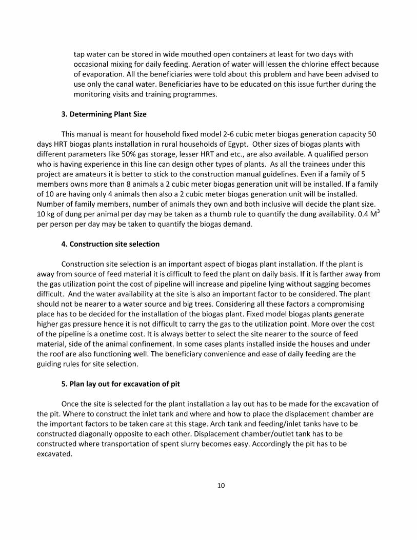
Figure: 5.1 Pit Layouts
A wooden or metal peg has to be inserted into the soil at the centre and a rope having equal
outside length of the digester basement concrete has to be tied to the peg to draw a circle for excavation. A rectangular portion for displacement chamber also has to be marked on the ground just touching the digester circle using rock dust or any other powder to be visible to the machine operator or the men who will dig the pit.
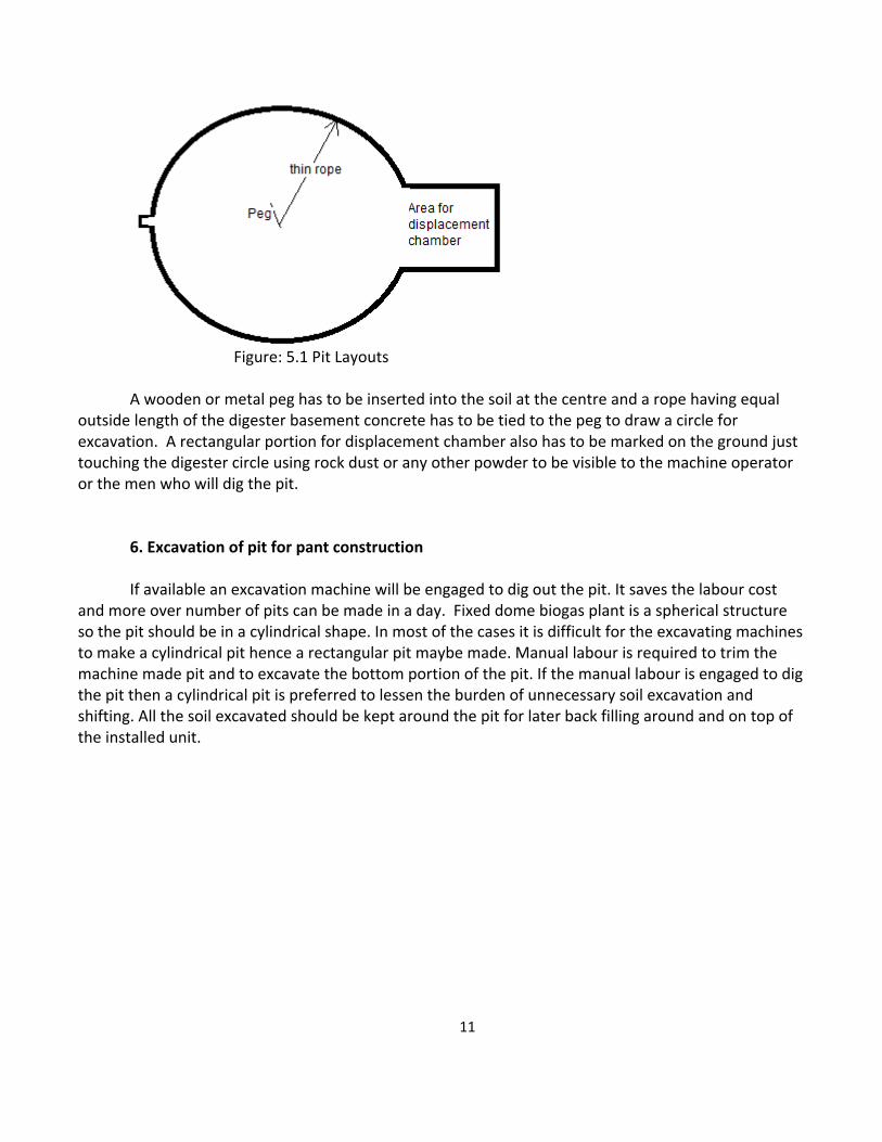
6. Excavation of pit for pant construction If available an excavation machine will be engaged to dig out the pit. It saves the labour cost
and more over number of pits can be made in a day. Fixed dome biogas plant is a spherical structure so the pit should be in a cylindrical shape. In most of the cases it is difficult for the excavating machines to make a cylindrical pit hence a rectangular pit maybe made. Manual labour is required to trim the machine made pit and to excavate the bottom portion of the pit. If the manual labour is engaged to dig the pit then a cylindrical pit is preferred to lessen the burden of unnecessary soil excavation and shifting. All the soil excavated should be kept around the pit for later back filling around and on top of the installed unit.
12
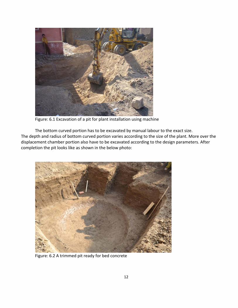
Figure: 6.1 Excavation of a pit for plant installation using machine The bottom curved portion has to be excavated by manual labour to the exact size.
The depth and radius of bottom curved portion varies according to the size of the plant. More over the displacement chamber portion also have to be excavated according to the design parameters. After completion the pit looks like as shown in the below photo:
Figure: 6.2 A trimmed pit ready for bed concrete
13
7. Casting the bed concrete
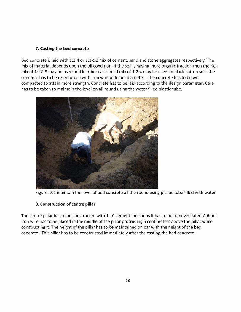
Bed concrete is laid with 1:2:4 or 1:1½:3 mix of cement, sand and stone aggregates respectively. The mix of material depends upon the oil condition. If the soil is having more organic fraction then the rich mix of 1:1½:3 may be used and in other cases mild mix of 1:2:4 may be used. In black cotton soils the concrete has to be re‐enforced with iron wire of 6 mm diameter. The concrete has to be well compacted to attain more strength. Concrete has to be laid according to the design parameter. Care has to be taken to maintain the level on all round using the water filled plastic tube.
Figure: 7.1 maintain the level of bed concrete all the round using plastic tube filled with water 8. Construction of centre pillar
The centre pillar has to be constructed with 1:10 cement mortar as it has to be removed later. A 6mm iron wire has to be placed in the middle of the pillar protruding 5 centimeters above the pillar while constructing it. The height of the pillar has to be maintained on par with the height of the bed concrete. This pillar has to be constructed immediately after the casting the bed concrete.
14
Figure: 8.1 Construction of centre pillar
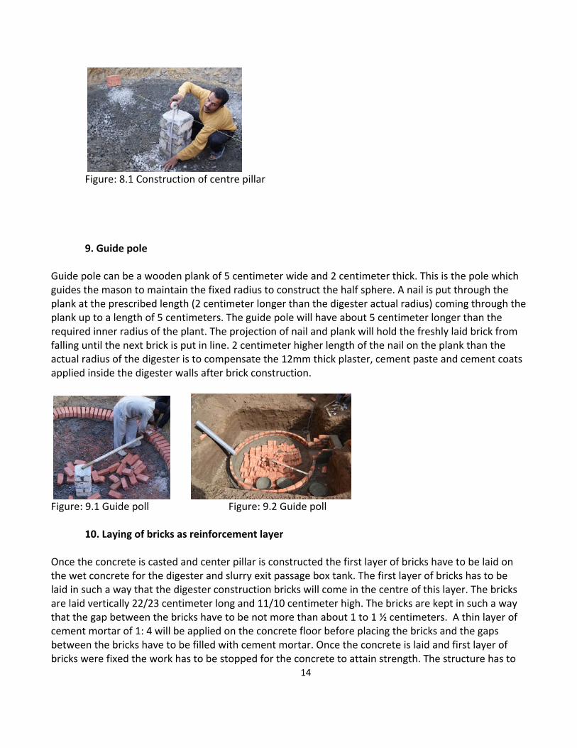
9. Guide pole Guide pole can be a wooden plank of 5 centimeter wide and 2 centimeter thick. This is the pole which guides the mason to maintain the fixed radius to construct the half sphere. A nail is put through the plank at the prescribed length (2 centimeter longer than the digester actual radius) coming through the plank up to a length of 5 centimeters. The guide pole will have about 5 centimeter longer than the required inner radius of the plant. The projection of nail and plank will hold the freshly laid brick from falling until the next brick is put in line. 2 centimeter higher length of the nail on the plank than the actual radius of the digester is to compensate the 12mm thick plaster, cement paste and cement coats applied inside the digester walls after brick construction.
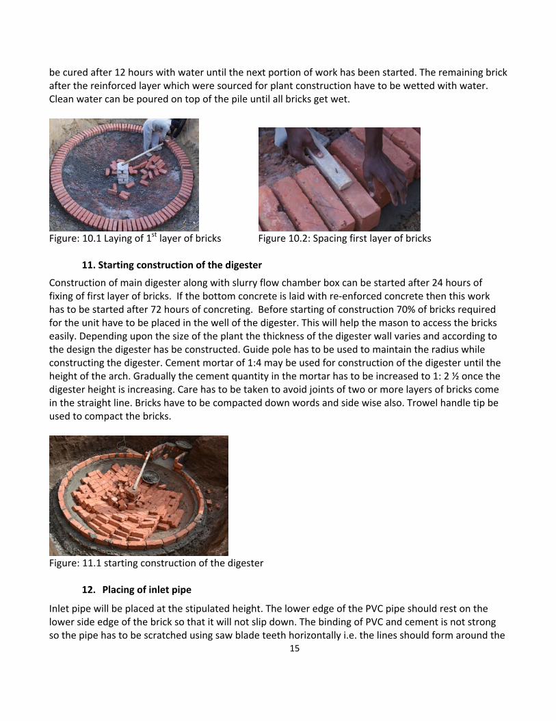
Figure: 9.1 Guide poll Figure: 9.2 Guide poll 10. Laying of bricks as reinforcement layer Once the concrete is casted and center pillar is constructed the first layer of bricks have to be laid on the wet concrete for the digester and slurry exit passage box tank. The first layer of bricks has to be laid in such a way that the digester construction bricks will come in the centre of this layer. The bricks are laid vertically 22/23 centimeter long and 11/10 centimeter high. The bricks are kept in such a way that the gap between the bricks have to be not more than about 1 to 1 ½ centimeters. A thin layer of cement mortar of 1: 4 will be applied on the concrete floor before placing the bricks and the gaps between the bricks have to be filled with cement mortar. Once the concrete is laid and first layer of bricks were fixed the work has to be stopped for the concrete to attain strength. The structure has to
15
be cured after 12 hours with water until the next portion of work has been started. The remaining brick after the reinforced layer which were sourced for plant construction have to be wetted with water. Clean water can be poured on top of the pile until all bricks get wet.
Figure: 10.1 Laying of 1st layer of bricks Figure 10.2: Spacing first layer of bricks
11. Starting construction of the digester
Construction of main digester along with slurry flow chamber box can be started after 24 hours of fixing of first layer of bricks. If the bottom concrete is laid with re‐enforced concrete then this work has to be started after 72 hours of concreting. Before starting of construction 70% of bricks required for the unit have to be placed in the well of the digester. This will help the mason to access the bricks easily. Depending upon the size of the plant the thickness of the digester wall varies and according to the design the digester has be constructed. Guide pole has to be used to maintain the radius while constructing the digester. Cement mortar of 1:4 may be used for construction of the digester until the height of the arch. Gradually the cement quantity in the mortar has to be increased to 1: 2 ½ once the digester height is increasing. Care has to be taken to avoid joints of two or more layers of bricks come in the straight line. Bricks have to be compacted down words and side wise also. Trowel handle tip be used to compact the bricks.
Figure: 11.1 starting construction of the digester
12. Placing of inlet pipe
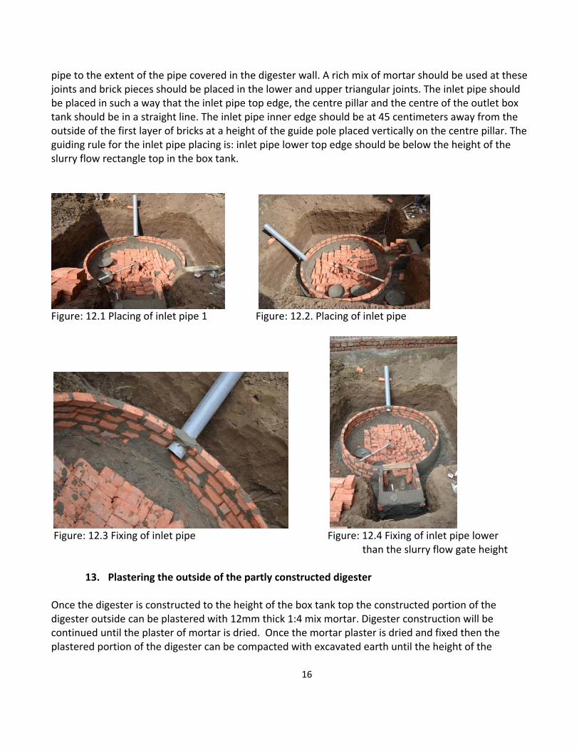
Inlet pipe will be placed at the stipulated height. The lower edge of the PVC pipe should rest on the lower side edge of the brick so that it will not slip down. The binding of PVC and cement is not strong so the pipe has to be scratched using saw blade teeth horizontally i.e. the lines should form around the
16
pipe to the extent of the pipe covered in the digester wall. A rich mix of mortar should be used at these joints and brick pieces should be placed in the lower and upper triangular joints. The inlet pipe should be placed in such a way that the inlet pipe top edge, the centre pillar and the centre of the outlet box tank should be in a straight line. The inlet pipe inner edge should be at 45 centimeters away from the outside of the first layer of bricks at a height of the guide pole placed vertically on the centre pillar. The guiding rule for the inlet pipe placing is: inlet pipe lower top edge should be below the height of the slurry flow rectangle top in the box tank.
Figure: 12.1 Placing of inlet pipe 1 Figure: 12.2. Placing of inlet pipe
Figure: 12.3 Fixing of inlet pipe Figure: 12.4 Fixing of inlet pipe lower
than the slurry flow gate height
13. Plastering the outside of the partly constructed digester Once the digester is constructed to the height of the box tank top the constructed portion of the digester outside can be plastered with 12mm thick 1:4 mix mortar. Digester construction will be continued until the plaster of mortar is dried. Once the mortar plaster is dried and fixed then the plastered portion of the digester can be compacted with excavated earth until the height of the
17
plastered area. Back filling of soil around the digester, apart from creating more working space for the workers to move but also compacts the soil around the digester.
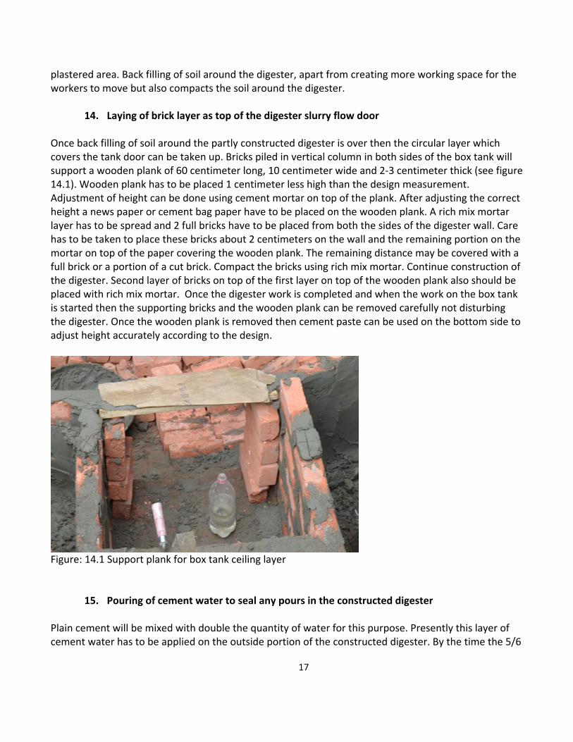
14. Laying of brick layer as top of the digester slurry flow door Once back filling of soil around the partly constructed digester is over then the circular layer which covers the tank door can be taken up. Bricks piled in vertical column in both sides of the box tank will support a wooden plank of 60 centimeter long, 10 centimeter wide and 2‐3 centimeter thick (see figure 14.1). Wooden plank has to be placed 1 centimeter less high than the design measurement. Adjustment of height can be done using cement mortar on top of the plank. After adjusting the correct height a news paper or cement bag paper have to be placed on the wooden plank. A rich mix mortar layer has to be spread and 2 full bricks have to be placed from both the sides of the digester wall. Care has to be taken to place these bricks about 2 centimeters on the wall and the remaining portion on the mortar on top of the paper covering the wooden plank. The remaining distance may be covered with a full brick or a portion of a cut brick. Compact the bricks using rich mix mortar. Continue construction of the digester. Second layer of bricks on top of the first layer on top of the wooden plank also should be placed with rich mix mortar. Once the digester work is completed and when the work on the box tank is started then the supporting bricks and the wooden plank can be removed carefully not disturbing the digester. Once the wooden plank is removed then cement paste can be used on the bottom side to adjust height accurately according to the design.
Figure: 14.1 Support plank for box tank ceiling layer
15. Pouring of cement water to seal any pours in the constructed digester Plain cement will be mixed with double the quantity of water for this purpose. Presently this layer of cement water has to be applied on the outside portion of the constructed digester. By the time the 5/6
18
layers of digester is constructed on top of the slurry flow door top this pouring of cement water activity can be taken up. This cement water should cover the entire newly constructed outside portion of the digester covering all the joints. If any holes appear after this water application the holes have to be covered with cement water or mortar if the holes are big. Plastering of this newly constructed portion can be taken up immediately when the cement water is still wet. Once this plastering is completed and the plaster is set the back filling of soil around the digester can be taken up.
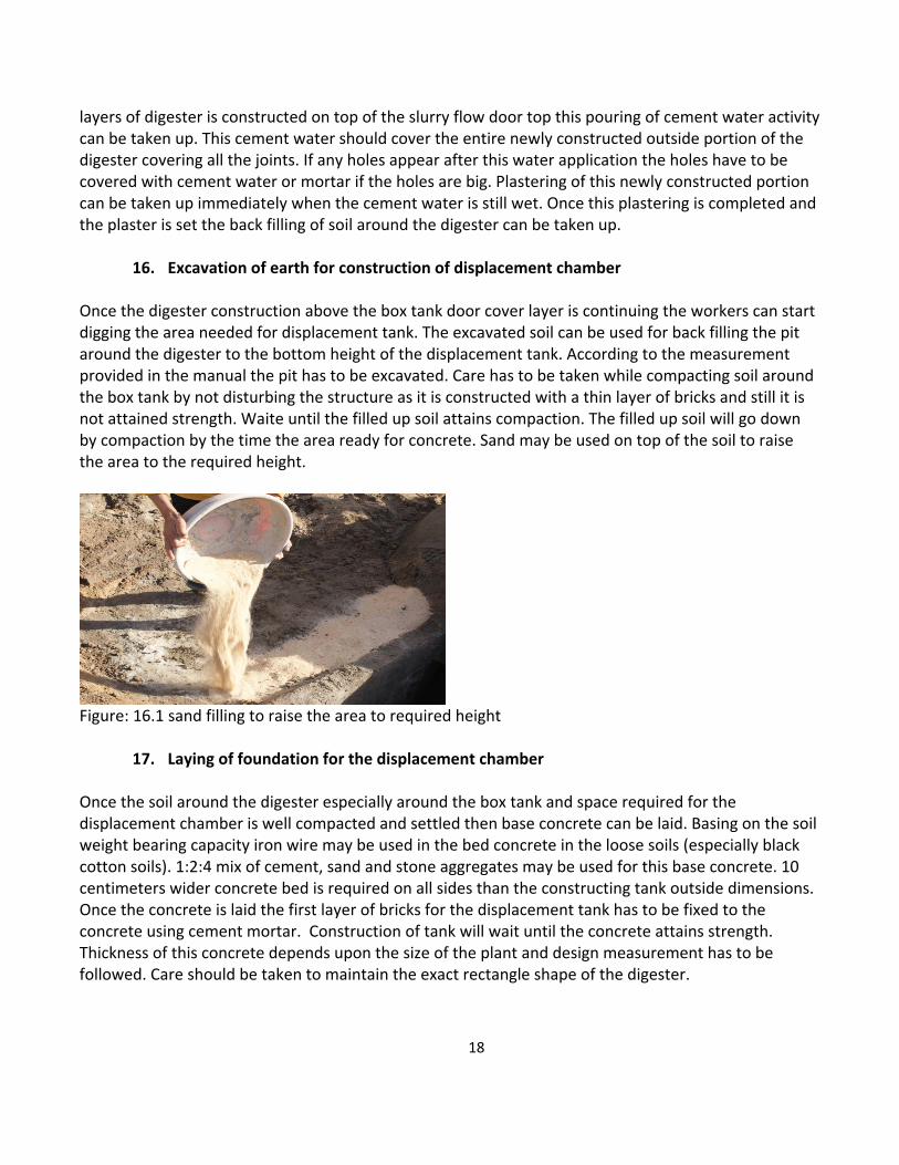
16. Excavation of earth for construction of displacement chamber Once the digester construction above the box tank door cover layer is continuing the workers can start digging the area needed for displacement tank. The excavated soil can be used for back filling the pit around the digester to the bottom height of the displacement tank. According to the measurement provided in the manual the pit has to be excavated. Care has to be taken while compacting soil around the box tank by not disturbing the structure as it is constructed with a thin layer of bricks and still it is not attained strength. Waite until the filled up soil attains compaction. The filled up soil will go down by compaction by the time the area ready for concrete. Sand may be used on top of the soil to raise the area to the required height.
Figure: 16.1 sand filling to raise the area to required height
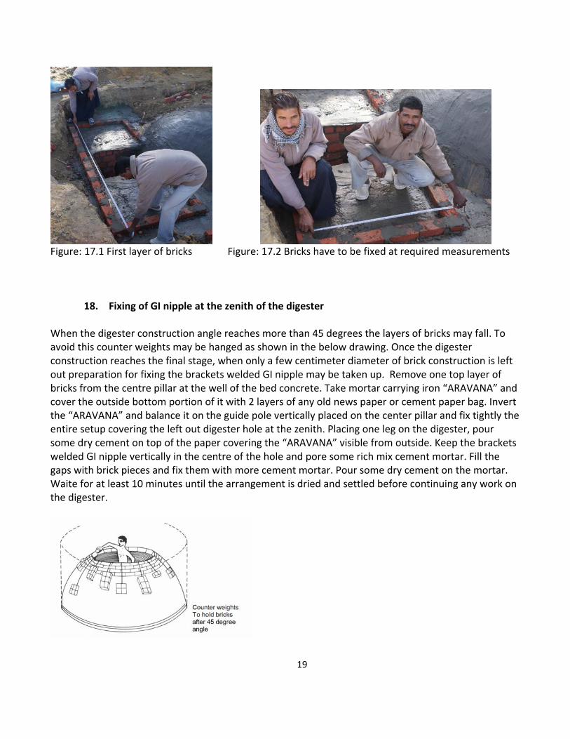
17. Laying of foundation for the displacement chamber Once the soil around the digester especially around the box tank and space required for the displacement chamber is well compacted and settled then base concrete can be laid. Basing on the soil weight bearing capacity iron wire may be used in the bed concrete in the loose soils (especially black cotton soils). 1:2:4 mix of cement, sand and stone aggregates may be used for this base concrete. 10 centimeters wider concrete bed is required on all sides than the constructing tank outside dimensions. Once the concrete is laid the first layer of bricks for the displacement tank has to be fixed to the concrete using cement mortar. Construction of tank will wait until the concrete attains strength. Thickness of this concrete depends upon the size of the plant and design measurement has to be followed. Care should be taken to maintain the exact rectangle shape of the digester.
19
Figure: 17.1 First layer of bricks Figure: 17.2 Bricks have to be fixed at required measurements
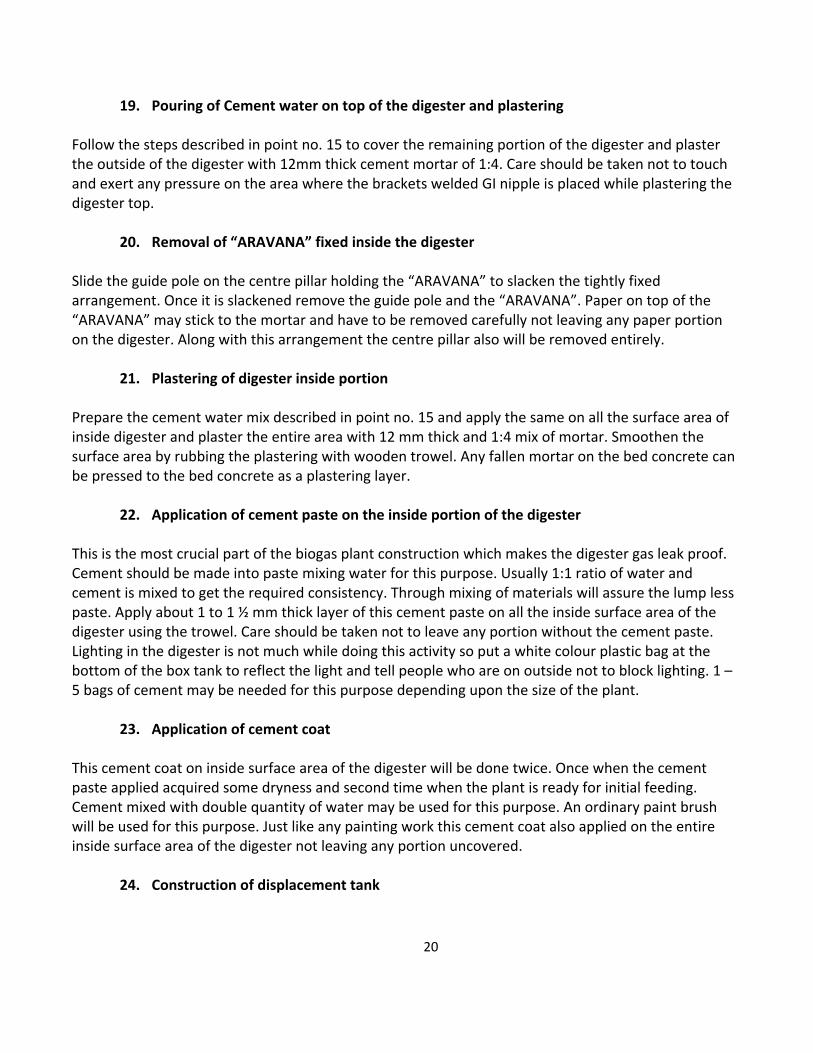
18. Fixing of GI nipple at the zenith of the digester When the digester construction angle reaches more than 45 degrees the layers of bricks may fall. To avoid this counter weights may be hanged as shown in the below drawing. Once the digester construction reaches the final stage, when only a few centimeter diameter of brick construction is left out preparation for fixing the brackets welded GI nipple may be taken up. Remove one top layer of bricks from the centre pillar at the well of the bed concrete. Take mortar carrying iron “ARAVANA” and cover the outside bottom portion of it with 2 layers of any old news paper or cement paper bag. Invert the “ARAVANA” and balance it on the guide pole vertically placed on the center pillar and fix tightly the entire setup covering the left out digester hole at the zenith. Placing one leg on the digester, pour some dry cement on top of the paper covering the “ARAVANA” visible from outside. Keep the brackets welded GI nipple vertically in the centre of the hole and pore some rich mix cement mortar. Fill the gaps with brick pieces and fix them with more cement mortar. Pour some dry cement on the mortar. Waite for at least 10 minutes until the arrangement is dried and settled before continuing any work on the digester.
20
19. Pouring of Cement water on top of the digester and plastering Follow the steps described in point no. 15 to cover the remaining portion of the digester and plaster the outside of the digester with 12mm thick cement mortar of 1:4. Care should be taken not to touch and exert any pressure on the area where the brackets welded GI nipple is placed while plastering the digester top.
20. Removal of “ARAVANA” fixed inside the digester Slide the guide pole on the centre pillar holding the “ARAVANA” to slacken the tightly fixed arrangement. Once it is slackened remove the guide pole and the “ARAVANA”. Paper on top of the “ARAVANA” may stick to the mortar and have to be removed carefully not leaving any paper portion on the digester. Along with this arrangement the centre pillar also will be removed entirely.
21. Plastering of digester inside portion Prepare the cement water mix described in point no. 15 and apply the same on all the surface area of inside digester and plaster the entire area with 12 mm thick and 1:4 mix of mortar. Smoothen the surface area by rubbing the plastering with wooden trowel. Any fallen mortar on the bed concrete can be pressed to the bed concrete as a plastering layer.
22. Application of cement paste on the inside portion of the digester This is the most crucial part of the biogas plant construction which makes the digester gas leak proof. Cement should be made into paste mixing water for this purpose. Usually 1:1 ratio of water and cement is mixed to get the required consistency. Through mixing of materials will assure the lump less paste. Apply about 1 to 1 ½ mm thick layer of this cement paste on all the inside surface area of the digester using the trowel. Care should be taken not to leave any portion without the cement paste. Lighting in the digester is not much while doing this activity so put a white colour plastic bag at the bottom of the box tank to reflect the light and tell people who are on outside not to block lighting. 1 – 5 bags of cement may be needed for this purpose depending upon the size of the plant.
23. Application of cement coat This cement coat on inside surface area of the digester will be done twice. Once when the cement paste applied acquired some dryness and second time when the plant is ready for initial feeding. Cement mixed with double quantity of water may be used for this purpose. An ordinary paint brush will be used for this purpose. Just like any painting work this cement coat also applied on the entire inside surface area of the digester not leaving any portion uncovered.
24. Construction of displacement tank
21
Once the base concrete attains strength the displacement tank construction can be taken up. A hole for slurry exit has to be left out while constructing the displacement tank. This exit hole can be kept on any side of the displacement tank depending upon the need of the household. Until the height of the slurry exit hole a rough plastering on outside portion and all remaining portion fine plastering has to be done.
25. Casting of concrete slabs / plates meant for covering the displacement tank This work can be taken up on the day of bed concrete laying or any other convenient day of plant installation. Each plate will have to be casted with 60 – 70 centimeter width, 120 – 140 centimeter length and with 6 – 8 thickness. 6 mm iron wire cut to the required measures will be used in these plates. Depending upon the size of the plant 3 – 6 plates are required. 1 : 1 ½ : 3 mix of cement, sand and stone aggregates may be used for these slabs. 4 vertical and 5 ‐ 6 horizontal iron wires are required for each plate. Clear an area to the extent of the plates’ requirement and level the ground using shawl. Cover the area with 1‐2 centimeter thick sand layer. Put empty paper cement bags or 2 layers of old news papers on leveled and sand covered area. Place bricks on outside of exact plate dimensions forming a rectangle. One layer of bricks can be use as one side for 2 plates. Cover the bricks with paper in such a way that the concrete do not stick to them. Pour concrete mix to the extent of 2 centimeter thickness and place the iron wires vertically and horizontally and bind all the joints with thin iron wire. Pour more concrete mix on top of the wires and compact the concrete with trowel initially and later with a wooden plank. All the required plates can be made at the same time.
26. Construction of inlet tank While the displacement tank is under construction the area required for inlet tank has to be raised for laying of bed concrete. Once this soil is compacted and well settled then bed concrete with 1:2:4 mix may be laid. At least 10 centimeter more lengthy area than the inlet tank outer area on all sides has to be covered with concrete. Once this concrete has attained sufficient strength then the inlet tank construction can be taken up according to the measurements mentioned in the manual.
27. Curing of civil works with water
This is another important factor for the longevity of the plants. All cement structures attain strength when they are cured with water. All the civil works including the concrete plates have to be cured with water for not less than 15 days. Curing has to be taken up in such a way that the civil works do not get dried completely. When all the civil works outsides are covered with soil it becomes easy to maintain moisture in the structures and lessen the burden of application of water number of times in a day.
28. Compacting of the civil works with soil The inlet tank, displacement tank and the digester should be compacted with soil on all outside portions. The digester top should be at least 10 centimeter under the soil and soil has to be covered
22
around the inlet tank at least 15 centimeters high on all sides. Except on the side where the slurry exit hole in the displacement chamber all other sides should be covered with soil to the height of the tank.
29. Digging of pit to collect spent slurry A hole in the ground has to be excavated just under the slurry exit hole in the displacement chamber to collect the slurry flowing out of the plant. The pit dimensions vary depending upon the size of the plant. The pit should be excavated in such a way that it should hold at least 10 days feed stock. A 2 cubic biogas generation per day capacity plant will be fed with 50 kg of dung and about 50 liters of water every day and hence the slurry collecting pit should have a capacity to hold 1000 liters of slurry.
30. Initial feeding of plant The plant requires big quantity of fresh animal dung and water to feed it initially. The plants were installed with 50 days hydraulic retention time and require 50 days feed stock as initial feed. A 2 cubic meter gas generation per day capacity plant requires 50 kg dung per day and hence 50 kg x 50 days i.e. 2500 kg of dung is required for initial feeding of the plant. Beneficiaries were advised to pile up the dung generated in their animal confinement on daily basis starting from the day of decision to install the plant in shaded area. The required dung for initial feeding will be accumulated on site by the time the plant is installed and completed curing. Initial feeding will be done using the irrigation water but not the tap water as it contains chorine, an anti bacterial material.
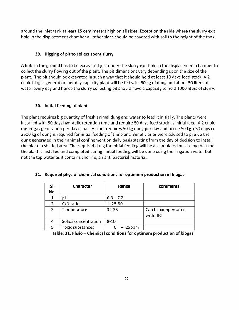
31. Required physio‐ chemical conditions for optimum production of biogas
Sl. No.
Character Range comments
1 pH 6.8 – 7.2
2 C/N ratio 1: 25‐30
3 Temperature 32‐35 Can be compensated with HRT
4 Solids concentration 8‐10
5 Toxic substances 0 – 25ppm
Table: 31. Phsio – Chemical conditions for optimum production of biogas
23
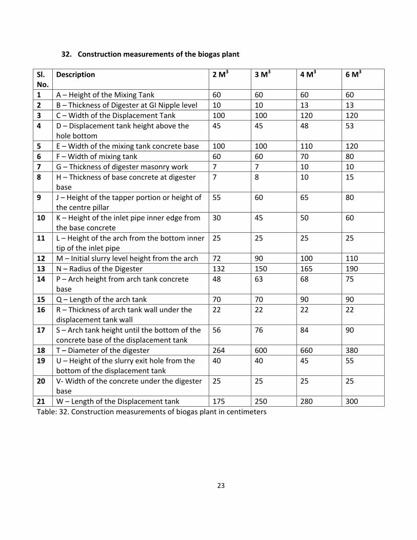
32. Construction measurements of the biogas plant
Sl. No.
Description 2 M3 3 M3 4 M3 6 M3
1 A – Height of the Mixing Tank 60 60 60 60
2 B – Thickness of Digester at GI Nipple level 10 10 13 13
3 C – Width of the Displacement Tank 100 100 120 120
4 D – Displacement tank height above the hole bottom
45 45 48 53
5 E – Width of the mixing tank concrete base 100 100 110 120
6 F – Width of mixing tank 60 60 70 80
7 G – Thickness of digester masonry work 7 7 10 10
8 H – Thickness of base concrete at digester base
7 8 10 15
9 J – Height of the tapper portion or height of the centre pillar
55 60 65 80
10 K – Height of the inlet pipe inner edge from the base concrete
30 45 50 60
11 L – Height of the arch from the bottom inner tip of the inlet pipe
25 25 25 25
12 M – Initial slurry level height from the arch 72 90 100 110
13 N – Radius of the Digester 132 150 165 190
14 P – Arch height from arch tank concrete base
48 63 68 75
15 Q – Length of the arch tank 70 70 90 90
16 R – Thickness of arch tank wall under the displacement tank wall
22 22 22 22
17 S – Arch tank height until the bottom of the concrete base of the displacement tank
56 76 84 90
18 T – Diameter of the digester 264 600 660 380
19 U – Height of the slurry exit hole from the bottom of the displacement tank
40 40 45 55
20 V‐ Width of the concrete under the digester base
25 25 25 25
21 W – Length of the Displacement tank 175 250 280 300
Table: 32. Construction measurements of biogas plant in centimeters
24
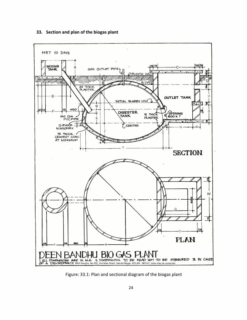
33. Section and plan of the biogas plant
Figure: 33.1: Plan and sectional diagram of the biogas plant
25
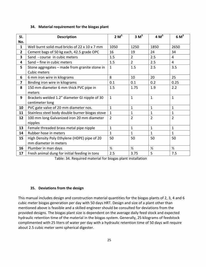
34. Material requirement for the biogas plant
Sl. No.
Description 2 M3 3 M3 4 M3 6 M3
1 Well burnt solid mud bricks of 22 x 10 x 7 mm 1050 1250 1850 2650
2 Cement bags of 50 kg each, 42.5 grade OPC 16 19 24 34
3 Sand ‐ course in cubic meters 1.5 2 2.5 4
4 Sand – fine in cubic meters 1.5 2 2.5 4
5 Stone aggregates – made from granite stone in Cubic meters
1 1.5 2.5 3.5
6 6 mm iron wire in kilograms 8 10 20 25
7 Binding iron wire in kilograms 0.1 0.1 0.2 0.25
8 150 mm diameter 6 mm thick PVC pipe in meters
1.5 1.75 1.9 2.2
9 Brackets welded 1.2” diameter GI nipple of 30 centimeter long
1 1 1 1
10 PVC gate valve of 20 mm diameter nos. 1 1 1 1
11 Stainless steel body double burner biogas stove 1 1 1 1
12 100 mm long Galvanized iron 20 mm diameter nipples
2 2 2 2
13 Female threaded brass metal pipe nipple 1 1 1 1
14 Rubber hose in meters 1 1 1 1
15 High Density Poly Ethylene (HDPE) pipe of 20 mm diameter in meters
50 50 50 50
16 Plumber in man days ½ ½ ½ ½
17 Fresh animal dung for initial feeding in tons 2.5 3.75 5 7.5
Table: 34. Required material for biogas plant installation
35. Deviations from the design This manual includes design and construction material quantities for the biogas plants of 2, 3, 4 and 6 cubic meter biogas generation per day with 50 days HRT. Design and size of a plant other than mentioned above is feasible and a skilled engineer should be consulted for deviations from the provided designs. The biogas plant size is dependent on the average daily feed stock and expected hydraulic retention time of the material in the biogas system. Generally, 25 kilograms of feedstock complimented with 25 liters of water per day with a hydraulic retention time of 50 days will require about 2.5 cubic meter semi spherical digester.