biologically inspired nanorovers: innovative and …epubs.surrey.ac.uk/725234/1/saaj_biologically...
TRANSCRIPT

BIOLOGICALLY INSPIRED NANOROVERS: INNOVATIVE AND LOW COST TECHNOLOGIES USING SHAPE MEMORY ALLOYS
Beatrice G. R. Smith, Dr. Chakravarthini M. SaajSurrey Space CentreUniversity of Surrey
Guildford, Surrey, GU2 7XH, [email protected], [email protected]
This paper details the design and construction of a biologically inspired nanorover prototype for exploring Mars. Although all Martian exploration vehicles to date have been wheeled, a six legged design was selected for this rover so as to improve its trafficability across rough terrains, since the main focus of this project was miniaturisation, with a goal of building a rover which weighed less than 1kg. To this end, shape memory alloy actuators were used instead of conventional rotary motors, due to their small size and mass, and carbon fibre was used as the main construction material. The rover was analysed using a combination of empirical results and computer simulation, in particular a simulation tool being developed at the University of Surrey called the Legged Performance and Traction Predicting Tool (LPTPT), with results suggesting that the design could be the basis of a successful planetary exploration vehicle.
I. INTRODUCTION:
One of the main limitations in planning a planetary exploration mission is that of mass; the greater the mass of the mission hardware, the more fuel is required to deliver it to it's final destination, and the more power it will require to move once it has arrived, and therefore the more expensive the mission will be. The solution proposed in this paper is a swarm of nanorovers, i.e. rovers with a mass less than 1kg. Each of these rovers will be biologically inspired legged vehicles, as it is believed that this will result in greater trafficability than if wheeled or tracked rovers. A prototype of one of these rovers was built, using shape memory alloy actuators rather than conventional motors to minimise mass, and the design and testing of this rover is described in the following paper.
II. STATE OF THE ART:
Nanorovers:
As yet, no missions utilising nanorovers have flown successfully, due to the difficulty of miniaturisation of components and payloads.
Fig. 1: Sojourner microrover [1]
Sojourner, a microrover flown as part of the Mars Pathfinder mission is the smallest rover which has successfully completed a mission. It was a six wheeled rover, 650mm long by 480mm wide by 300mm high, weighing 10.6 kg and carrying a solar panel capable of providing 16W peak power [2].
One of the main innovations of the Sojourner vehicle was its rocker bogie wheel arrangement; this meant that while its front two wheels were attached to its chassis, the other four were attached to a rocker; an strip of metal which pivoted about a point on the chassis. This meant that if Sojourner was moving over uneven ground its front wheels could lift while its back wheels would remain on the ground. This would improve traction and prevent the rover toppling. Sojourner's main instrument was an APXS (Alpha Proton X-ray Spectrometer) used to investigate the chemical position of rocks.
Further development of the Sojourner chassis came in 1996, with the start of the MUSES-C joint project between NASA and JAXA [3]. This mission was to investigate the Itokawa asteroid, and would carry a nanorover, based on Sojourner, but with further miniaturisation made possible by advances in electronics and materials technologies. Unlike the previous mission, this rover only had four wheels, weighed 1.1kg, and was 140mm x 140mm x 140mm. It carried no battery to reduce mass, with all its power being supplied by a solar panel which covered the top surface and three sides. IT carried a multispectral camera, and an APXS based on the Sojourner instrument. By 'scissoring' its wheel struts, the rover could lift its chassis up and down to improve the field of view with its camera, as well as hop to cover rough terrain faster. This hopping mechanism could also be used to self right. However, due to funding and time
1
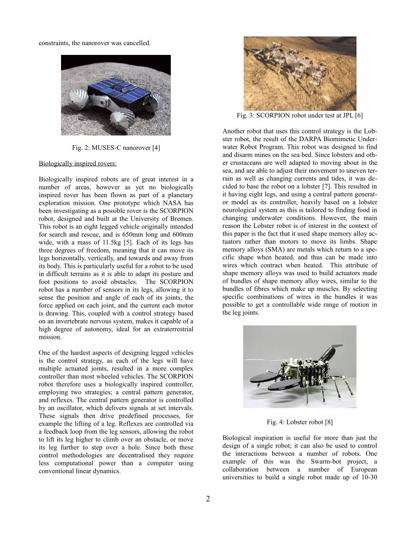
constraints, the nanorover was cancelled.
Fig. 2: MUSES-C nanorover [4]
Biologically inspired rovers:
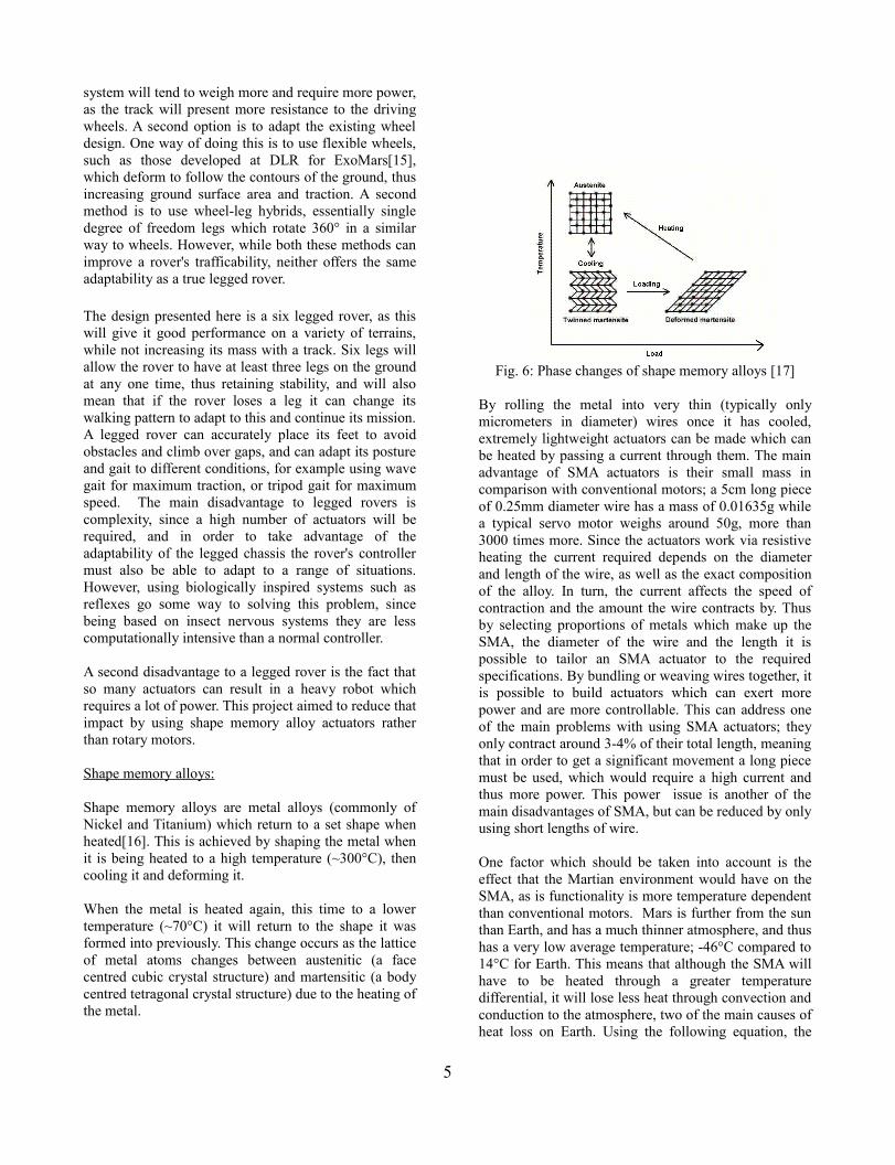
Biologically inspired robots are of great interest in a number of areas, however as yet no biologically inspired rover has been flown as part of a planetary exploration mission. One prototype which NASA has been investigating as a possible rover is the SCORPION robot, designed and built at the University of Bremen. This robot is an eight legged vehicle originally intended for search and rescue, and is 650mm long and 600mm wide, with a mass of 11.5kg [5]. Each of its legs has three degrees of freedom, meaning that it can move its legs horizontally, vertically, and towards and away from its body. This is particularly useful for a robot to be used in difficult terrains as it is able to adapt its posture and foot positions to avoid obstacles. The SCORPION robot has a number of sensors in its legs, allowing it to sense the position and angle of each of its joints, the force applied on each joint, and the current each motor is drawing. This, coupled with a control strategy based on an invertebrate nervous system, makes it capable of a high degree of autonomy, ideal for an extraterrestrial mission.
One of the hardest aspects of designing legged vehicles is the control strategy, as each of the legs will have multiple actuated joints, resulted in a more complex controller than most wheeled vehicles. The SCORPION robot therefore uses a biologically inspired controller, employing two strategies; a central pattern generator, and reflexes. The central pattern generator is controlled by an oscillator, which delivers signals at set intervals. These signals then drive predefined processes, for example the lifting of a leg. Reflexes are controlled via a feedback loop from the leg sensors, allowing the robot to lift its leg higher to climb over an obstacle, or move its leg further to step over a hole. Since both these control methodologies are decentralised they require less computational power than a computer using conventional linear dynamics.
Fig. 3: SCORPION robot under test at JPL [6]
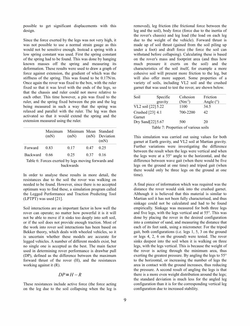
Another robot that uses this control strategy is the Lob-ster robot, the result of the DARPA Biomimetic Under-water Robot Program. This robot was designed to find and disarm mines on the sea bed. Since lobsters and oth-er crustaceans are well adapted to moving about in the sea, and are able to adjust their movement to uneven ter-rain as well as changing currents and tides, it was de-cided to base the robot on a lobster [7]. This resulted in it having eight legs, and using a central pattern generat-or model as its controller, heavily based on a lobster neurological system as this is tailored to finding food in changing underwater conditions. However, the main reason the Lobster robot is of interest in the context of this paper is the fact that it used shape memory alloy ac-tuators rather than motors to move its limbs. Shape memory alloys (SMA) are metals which return to a spe-cific shape when heated, and thus can be made into wires which contract when heated. This attribute of shape memory alloys was used to build actuators made of bundles of shape memory alloy wires, similar to the bundles of fibres which make up muscles. By selecting specific combinations of wires in the bundles it was possible to get a controllable wide range of motion in the leg joints.
Fig. 4: Lobster robot [8]
Biological inspiration is useful for more than just the design of a single robot; it can also be used to control the interactions between a number of robots. One example of this was the Swarm-bot project, a collaboration between a number of European universities to build a single robot made up of 10-30
2

smaller robots[9]. These small robots were called S-bots. Unlike many previous investigations into distributed intelligence, where there was only one controller whose processing was split over a number of robots, each S-bot could operate individually, as well in a group. This control strategy was inspired by swarming insects such as ants, which can form bridges to cross wide gaps, and help each other carry loads which would be too bulky and heavy for a single insect. Each S-bot has a circular chassis 116mm in diameter, with a rigid gripper and two flexible Velcro connectors, allowing it to join itself to other S-bots to make bridges, and pick objects up. There is also a ring of multicoloured LEDs around the edge of the chassis, which the S-bot can flash to communicate with the rest of the Swarm-bot. At first the S-bots were pre-programmed with specific behaviours, but a later experiment was to allow them to develop their own methods of communicating and solving problems.
Fig. 5: S-bots crossing an obstacle [10]
III. DESIGN PROCESS:
Sizing:
One commonly used method of characterising rover trafficability is to find its mean free path, i.e. the distance it can move in a straight line before it must turn to avoid an obstacle. However, this method was originally intended for wheeled rovers, and thus does not take into account the fact that a legged rover can adjust the angles of its legs to avoid rocks, or change the posture of its body to move over an obstacle. This means that any estimate of mean free path for a legged vehicle will be an underestimate. Nevertheless, the calculated value for mean free path will give some indication of the rover's performance, especially as no equivalent calculation exists for legged vehicles.
Mean free path can be calculated using the Golombek rock distribution law, taking variables of the turning circle of the rover, its rock clearance, and the rock size and distribution of the surrounding area [11].
∫ ∫
∫ ∫
+
−−
= x
D
x
D
x
D
x
D
dDDDdDDr
dDDDdDDDr
MFP
0 0
0 0
)()(
)(21)(
21 2
ρρ
ρρ
Where r = rover turning circle, and D = rock diameter.
This equation shows that the greater the turning circle of the rover (i.e. the larger the rover's chassis is), the lower its mean free path. This demonstrates one of the advantages of a nanorover over a micro rover because a smaller rover can fit into the gaps between rocks easier than a larger rover, even if it does not have as great a rock clearance. It was therefore decided to build the rover to be as small as possible, so as to take advantage of this, as well as the saving in mass.
Chassis Design:
The chassis of the rover must be small and light, while still being able to carry a payload and control hardware. Clearly one of the main limitations in reducing rover size and mass is the size of the payload; although advances are continuously being made in instrument technology and miniaturisation, there are still only a limited number of options. However, a number of possible payloads which would be suitable for a nanorover have been identified.
One of the most important instruments carried by planetary exploration vehicles is a spectrometer. These instruments work by bombarding an object with α particles and measuring the resulting backscattered radiation. The spectrum of this radiation can be used to determine the elements that make up the object. This is of particular use in planetary exploration as it can be used to measure concentrations of elements used to build biological systems such as carbon, oxygen and nitrogen, or useful materials such as iron. One option for a spectrometer for a nanorover would be the Hamamatsu optical spectrometer, which has dimensions of 25.4mm cubed [12]. A second option for detecting various chemical compounds might be an electronic nose. These are commonly used for detecting dangerous gasses in situations such as mining or on the International Space Station, or for detecting chemical and biological threats by anti-terrorist units. One miniaturised example of an electronic nose was designed and built by the University of Tennessee and the Technical University of Denmark [13]. This instrument was made using MEMS technology, resulting in an extremely small package. The electronic nose was made up of four cantilevers; one side of each
3

was coated in a layer of gold and a layer of titanium, and the other side was coated in an acid which would react with the substance the sensor was designed to detect. When the sensor came into contact with a chemical it would bend, the degree to which it bent could then be measured and a pattern matching neural network could be used to identify the compound based on this data. By using different coatings, different chemical substances can be found. The small size of the sensor would allow a number of different sensors to be carried in one package, and would allow the rover to search for a wide range of different compounds which would suggest life.
A second type of payload which is useful for rovers is a sampling tool. A variety of tools exist, including scoops, drills, raspers and coring tools. Regarding the design of the rover, if a sampling tool is required then the rover must not only be able to carry the tool, but must also be capable of either carrying the sample back to the lander for analysis, or analysing the sample in situ. Scoops are one of the simplest sampling tools, and have the advantage that the sample can often be stored in the scoop itself, negating the need for a separate container. However, this also means that the scoop itself must be fairly large so as to be able to hold a significant amount of sample. Scoops can also only pick up soft soil from near the surface, and thus cannot be used to investigate the lower soil. Drills and coring tools are much more useful for this, as they can be pushed through the top layer and into the lower soil. Drills work by cutting into the soil and lifting the shavings into a hopper, while coring tools do not rotate, they just push into the soil and when drawn out are full of a sample. They are most useful for investigating changes in layers of soil. One of the major issues for both these samplers is that the size of sampler which could be carried is not very large, meaning that sample collection would be slow, and could not be done to any great depth. Raspers are covered with serrations which are rubbed against on object of interest to remove a layer. This can then be collected and analysed, or the layer underneath can be investigated with a spectrometer as described above. This is particularly useful when trying to determine what the effect of the environment (e.g. weathering due to wind, precipitation) has been on the rock.
A final payload is a robotic arm. This is the most complex payload, and would result in significant increases in mass and power requirements, however it could lead to a great deal of versatility, for example the arm could have access to a variety of different samplers, and could switch between them to select the most appropriate one. An arm might also allow the rover to self right, or co-operate with other rovers in a similar way to the S-bots described above. As with the other
payloads the main issue is one of designing an arm small enough to be carried on a nanorover without it being too weak to carry any tools. A number of solutions to the problem of miniaturising robot arms have been investigated; a four degree of freedom arm with a total length of only 120mm was designed at the University of Washington [14]. The arm was actuated using motors from hard disk drives, which have the advantage of being small, as well as easily available and cheap.
The chassis itself is designed in two sections, similar to the thorax and abdomen in an insect. These two sections are connected by a passive joint, allowing them to move independently. This means that the front two legs can be lifted onto an obstacle while the back four legs remain on the lower ground, or that the rover can flex to get better traction when moving onto or off a slope. In this way it is similar to the rocker bogie system used by Sojourner and the MER vehicles. The middle legs are offset to further spread the load of the vehicle and improve stability.
Fig. 6: Rover chassis design
Locomotion:
Although research is being done into tracked systems (e.g. Nanokhod) and legged systems (e.g. SCORPION) all planetary rovers up to this point have been wheeled vehicles. This is due to the fact that it is much simpler to control a wheeled vehicle, and there is a wide body of research to draw from in designing these vehicles. However, wheeled vehicles have a number of disadvantages; they work best on hard flat terrain, which is uncommon in the environments where rover missions usually take place, and they have problems with traction due to the low contact area with the ground.
One option to improve traction is to use tracks. This results in a larger ground contact area, and thus higher traction, as well as spreading the rover's weight across a wider area, reducing sinkage. However, a tracked
4
system will tend to weigh more and require more power, as the track will present more resistance to the driving wheels. A second option is to adapt the existing wheel design. One way of doing this is to use flexible wheels, such as those developed at DLR for ExoMars[15], which deform to follow the contours of the ground, thus increasing ground surface area and traction. A second method is to use wheel-leg hybrids, essentially single degree of freedom legs which rotate 360° in a similar way to wheels. However, while both these methods can improve a rover's trafficability, neither offers the same adaptability as a true legged rover.
The design presented here is a six legged rover, as this will give it good performance on a variety of terrains, while not increasing its mass with a track. Six legs will allow the rover to have at least three legs on the ground at any one time, thus retaining stability, and will also mean that if the rover loses a leg it can change its walking pattern to adapt to this and continue its mission. A legged rover can accurately place its feet to avoid obstacles and climb over gaps, and can adapt its posture and gait to different conditions, for example using wave gait for maximum traction, or tripod gait for maximum speed. The main disadvantage to legged rovers is complexity, since a high number of actuators will be required, and in order to take advantage of the adaptability of the legged chassis the rover's controller must also be able to adapt to a range of situations. However, using biologically inspired systems such as reflexes go some way to solving this problem, since being based on insect nervous systems they are less computationally intensive than a normal controller.
A second disadvantage to a legged rover is the fact that so many actuators can result in a heavy robot which requires a lot of power. This project aimed to reduce that impact by using shape memory alloy actuators rather than rotary motors.
Shape memory alloys:
Shape memory alloys are metal alloys (commonly of Nickel and Titanium) which return to a set shape when heated[16]. This is achieved by shaping the metal when it is being heated to a high temperature (~300°C), then cooling it and deforming it.
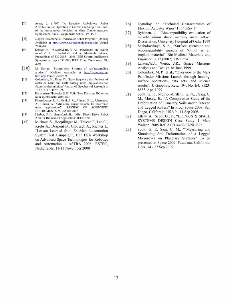
When the metal is heated again, this time to a lower temperature (~70°C) it will return to the shape it was formed into previously. This change occurs as the lattice of metal atoms changes between austenitic (a face centred cubic crystal structure) and martensitic (a body centred tetragonal crystal structure) due to the heating of the metal.
Fig. 6: Phase changes of shape memory alloys [17]
By rolling the metal into very thin (typically only micrometers in diameter) wires once it has cooled, extremely lightweight actuators can be made which can be heated by passing a current through them. The main advantage of SMA actuators is their small mass in comparison with conventional motors; a 5cm long piece of 0.25mm diameter wire has a mass of 0.01635g while a typical servo motor weighs around 50g, more than 3000 times more. Since the actuators work via resistive heating the current required depends on the diameter and length of the wire, as well as the exact composition of the alloy. In turn, the current affects the speed of contraction and the amount the wire contracts by. Thus by selecting proportions of metals which make up the SMA, the diameter of the wire and the length it is possible to tailor an SMA actuator to the required specifications. By bundling or weaving wires together, it is possible to build actuators which can exert more power and are more controllable. This can address one of the main problems with using SMA actuators; they only contract around 3-4% of their total length, meaning that in order to get a significant movement a long piece must be used, which would require a high current and thus more power. This power issue is another of the main disadvantages of SMA, but can be reduced by only using short lengths of wire.
One factor which should be taken into account is the effect that the Martian environment would have on the SMA, as is functionality is more temperature dependent than conventional motors. Mars is further from the sun than Earth, and has a much thinner atmosphere, and thus has a very low average temperature; -46°C compared to 14°C for Earth. This means that although the SMA will have to be heated through a greater temperature differential, it will lose less heat through convection and conduction to the atmosphere, two of the main causes of heat loss on Earth. Using the following equation, the
5

power required to heat 10mm of 150μm diameter wire, at both room temperature (20°C) and average Martian temperature (-46°C) and over a time period of 1 second, was calculated:
P = mcΔT
where: m = mass of wirec =specific heat capacity of Nitinol: 837.4 J (kgK)-1ΔT = change in temperature i.e. the increase in temperature required to heat the Nitinol to 70°C
Mass of wire (g)
Resistance (Ω)
Power required at 20°C (W)
Power required at -46°C(W)
0.0046 0.49 0.19 0.44Table 1: Power required to actuate Nitinol on Earth and
on Mars
This shows that a significant increase in power is required to heat the SMA on Mars.
The fact that the SMA will be insulated by the lack of atmosphere could cause problems when trying to cool the actuators to relax them. This can be illustrated by calculating the time taken for an SMA wire to cool down purely by radiation:
4TAtTmc
surfaceε σ=∂
∆
Where:
δt = time periodm = mass of wirec =specific heat capacity of Nitinol: 837.4 J (kgK)-1
ΔT = change in temperature (in this case 10K, as this is the temperature difference over the phase change)Asurface = Surface area of 10mm of 150μm diameter wireε = typical emissivity of unpolished metal (0.15)σ = Stefan-Boltzmann constant (5.67 x 10⁻⁸ Wm-2K-4)T = activation temperature (70°C or 351K)
The result for this calculation is that it would take 589 seconds to lose this heat using just radiation. Clearly this would mean that the rover would not be able to move very fast! The reason for this long time is because of the extremely small surface area of the wire. This means that some form of cooling is essential if the SMA is to be used repetitively within a short time period. A passive system could be used, for example a heat sink to increase the surface area, but this might also impact the heating time and power required. A second option
would be an active system, e.g. a Peltier cooler which transfers heat when a current is passed through it. A Peltier cooler has the advantage of being small and solid state, so no complex moving parts are required, as well as being easily controllable, by changing the current through the device, and could be used to transfer heat away from the SMA and to a heat sink with a high surface area which would allow the heat to be dissipated.
Two further aspects of the Martian environment are radiation and gravity; Mars is smaller than the Earth, and thus has lower gravity (3.69ms-2 compared to 9.81ms-2 on Earth). The low gravity is actually an advantage as the rover will sink into the ground less, and will require less power to lift its legs, however it also means that there is little to no convection in the atmosphere. Since Mars does not have a strong magnetic field it has a much more extreme radiation environment than Earth due to the solar wind. Little data is available for the effect that this radiation would have on the Nitinol, however it is commonly used in medical instruments, where is is sterilised via γ-radiation [18]. In this case it has been observed that, like other titanium alloys it forms an oxide layer, protecting the material beneath. The result of this would be that the effective diameter of the wire would be reduced, and thus less current required to actuate it. However, it may be necessary to use a thicker wire initially, to take the reduced effective diameter into account in case it prevents the wire conducting entirely.
Leg Design:
It was decided to have two degree of freedom legs, one joint for horizontal movement and one joint for vertical movement. This was to minimise the complexity of the legs, while still allowing them to lifted. The legs would be lifted using SMA, and would return to their position using a spring. Horizontal movement would be achieved using SMA. A number of different designs were considered, and were evaluated on the basis of estimated mass, estimated length of SMA required (and therefore power required), and range of movement of the leg.
Once a design had been selected a number of prototypes were built to investigate the best way to attach the SMA actuator. The best placement would be the one which would give the greatest range of movement while using as little SMA as possible. Simplicity and reliability were also important considerations. The three methods considered were; SMA connected directly to the lower leg segment (design 1), SMA connected to a gear train with a 2:1 ratio (design 2), and SMA connected to a spur protruding from the lower leg segment (design 3). In
6

each case a 70mm length of 150μm diameter SMA was used. The leg was fixed to a piece of paper, and the position of the bottom of the lower leg segment and the angle between the two leg segments was measured. 2.5V was then applied to the leg, so that the SMA would contract and move the leg. The position of the end of the leg and the angle between the two segments was then measured again. The results were as follows:
Design Displacement (mm) Angle (°)
1 3.25 19
2 14.06 41
3 8.65 32Table 2: Movement of leg with Nitinol attached in
various ways
Although design 2, i.e. the design using the gear train, resulted in the greatest displacement, it was decided to use a combination of designs 1 and 3, as these would be less susceptible to damage from dust than gears, which might become clogged and thus no longer move. The final design is shown below.
Figure 8: Leg design
Materials:
The materials, which the rover is made of, will have a significant impact on its mass, however the environment in which the rover will be operating is also an important factor. Not only do the materials have to be suitable for use on Mars, but they must also survive the journey from Earth and atmospheric entry and landing. Thus the rover will be exposed to both extremely high and extremely low temperatures, strong vibrations at launch and when landing, as well as the vacuum and harsh radiation environment of space. The characteristics of a number of commonly used materials are detailed below:
Material Density(g/cm3)
Tensile strength(MPa)
Youngs modulus (Msi)
Co-efficientofthermalexpansion
Aluminium 2.71 455 10.2 22.9
Titanium 4.51 900 110 8.8
Carbon composite
1.75 5650 34 0.8
Table 3: Properties of some commonly used materials [19]
From this table it is clear that carbon composite will offer the highest strength for the lowest mass, as well as having a low co-efficient of thermal expansion, which will limit how much it expands and contracts as it is heated and cooled, and thus limit the stresses on it. However, carbon composite is made up of carbon fibres held together by a resin, and thus cannot be worked as easily as metals to make complex shapes. For this reason the rover was made mostly of carbon composite, with part such as hinges which would be difficult to manufacture out of carbon composite made from aluminium.
Figure 9: Chassis undergoing testing
Controller Design:
Since the focus of this project was on the hardware design, the control of the rover is fairly simple. The controller is a PIC18f4221 microcontroller, selected due to its low power requirements, its high number of input and output pins and its compatibility with a number of C compilers.
The program itself was designed with adaptability as a high priority; functions were written for each leg, to move them backwards and forwards. By calling these functions in a specific order various gaits could be selected, and the robot could turn right or left. The various combinations were also programmed as functions, to make it easy to select the appropriate gait or turn. In the case of this prototype the controller was
7

connected to a computer via an RS232 connector, with a serial connection managed by a Maxim 232 chip on the controller end, and HyperTerminal on the computer end. By pressing keys on the keyboard the user could select which functions to call, for example if 'w' was pressed the robot would walk forwards using wave gait. However, a further development might be to give the robot the ability to select its own path, and its own gait.
IV. TESTING AND RESULTS:
The system was tested on three different types of criteria; physical characteristics (e.g. mass, dimensions) mechanical characteristics (e.g. force exerted by legs, sinkage) and electrical characteristics (e.g. current drawn)
Physical Characteristics:
The physical characteristics which were measured were length (measured from the front of the rover to the tip of the tail while standing normally), width (measured from the tips of the central legs when the rover's legs were both vertical, and at 55° to horizontal) and rock clearance (measured from the surface the rover is standing on to the bottom of its chassis when the rover's legs were both vertical, and at 55° to horizontal). Once these were known the turning circle and the mean free path of the rover could be calculated. These dimensions were measured using a ruler. The mass of the rover was also measured, using a set of digital scales. These values are shown below, with the corresponding values of the Sojourner rover and a Lynxmotion H3, a commercially available hexapod robot. Mean free path was calculated using rock distribution values for Viking landing site 2.
Nanorover (legs vertical)
Nanorover (legs at 55°)
Lynxmotion H3
Sojourner[20]
Length (mm)
214 214 230 630
Width (mm)
137 188 280 480
Turning circle (mm)
254.1 284.85 362.4
792
Rock clearance (mm)
45
37 45 130
Mean Free path (m)
27.0 25.3 23.3 21.1
Mass (kg) 0.17 0.17 1.2 10.6
Table 4: Comparison of various systems
As can be seen from the table, the nanorover is the smallest of the three systems, thus giving it the longest mean free path as it can fit through smaller gaps. Even though both the Lynxmotion H3 and nanorover have significantly smaller rock clearances than Sojourner, they still have long mean free paths, as VL2 is covered in many small rocks close together, rather than fewer larger rocks with greater distances between them.
Both the Lynxmotion robot and the nanorover are significantly lighter than Sojourner, due to their size and materials. Sojourner was made mostly of aluminium, while the Lynxmotion H3's chassis is plastic and the nanorover is carbon fibre and aluminium. Even though the difference in size between the H3 and the nanorover is only a few centimetres, the H3 weighs seven times as much. This illustrates the saving in mass due to using SMA actuators rather than motors; Each 80mm length of SMA weighs 0.009g, while each servo motor in the H3 weighs 62g.
Mechanical Characteristics
Two aspects of the rover were measured; the force and displacement of the legs due to the SMA moving them, and the interactions between the legs and the soil that the rover was walking on.
The displacement of the legs was measured by fixing the rover onto a box so that the legs were free to move but the chassis was stationary. Next a ruler was fixed below the chassis so that it was level with the ends of the legs. The initial position of a leg on the ruler was noted, then the SMA powered and the final position of the leg measured. This was done for each actuator of each leg separately.
Maximum (mm)
Minimum (mm)
Mean(mm)
Standard Deviation(mm)
Forward 7 2.5 4.42 1.88
Backward 9 3 5.25 2.04
Vertical 12 2 4.75 3.41Table 5: Displacement of the legs
In all cases there was significant standard deviation. This was due to the fact that the SMA was connected to the circuit using crimps, and thus would often come loose and slip out. This meant that the tension in the SMA would be lost, and thus the contraction of the wire would just result in the tension increasing in the wire, rather than moving the leg. However, since all the horizontal actuators were identical and all the vertical actuators were identical these results show that it is
8
possible to get significant displacements with this design.
Since the force exerted by the legs was not very high, it was not possible to use a normal strain gauge as this would not be sensitive enough. Instead a spring with a low spring constant was used. First the spring constant of the spring had to be found. This was done by hanging known masses off the spring and measuring its deformation. These results were used to draw a graph of force against extension, the gradient of which was the stiffness of the spring. This was found to be 0.17N/m. Once again the rover was fixed to the box, with the ruler fixed so that it was level with the ends of the legs, so that the chassis and ruler could not move relative to each other. This time however, a pin was fixed to the ruler, and the spring fixed between the pin and the leg being measured in such a way that the spring was relaxed and parallel with the ruler. The leg was then activated so that it would extend the spring and the extension measured using the ruler.
Maximum (mN)
Minimum (mN)
Mean (mN)
Standard Deviation (mN)
Forward 0.83 0.17 0.47 0.25
Backward 0.66 0.25 0.37 0.16Table 6: Forces exerted by legs moving forwards and
backwards
In order to analyse these results in more detail, the resistances due to the soil the rover was walking on needed to be found. However, since there is no accepted optimum way to find these, a simulation program called the Legged Performance and Traction Predicting Tool (LPTPT) was used [21].
Soil interactions are an important factor in how well the rover can operate; no matter how powerful it is it will not be able to move if it sinks too deeply into soft soil, or if the soil does not provide enough traction. Most of the work into rover soil interactions has been based on Bekker theory, which deals with wheeled vehicles, so it is uncertain whether these models are accurate for legged vehicles. A number of different models exist, but no single one is accepted as the best. The main factor used in determining rover performance is drawbar pull (DP), defined as the difference between the maximum forward thrust of the rover (H), and the resistances working against it (R).
These resistances include active force (the force acting on the leg due to the soil collapsing when the leg is
removed), leg friction (the frictional force between the leg and the soil), body force (force due to the inertia of the rover's chassis) and leg load (the load on each leg due to the weight of the vehicle). Forward thrust is made up of soil thrust (gained from the soil piling up under a foot) and draft force (the force the soil can withstand before collapsing). Calculating these is based on the rover's mass and footprint area (and thus how much pressure it exerts on the soil) and the characteristics of the soil itself, for example a more cohesive soil will present more friction to the leg, but will also offer more support. Some properties of a variety of soils, including VL2 soil and the crushed garnet that was used to test the rover, are shown below.
Soil Specific gravity
Cohesion (Nm-2)
Friction Angle (°)
VL2 soil [22] 5.22 1100 34.5Crushed [23] Garnet
4.1 700-2200 42
Dry Sand[22] 5.67 500 20Table 7: Properties of various soils
This simulation was carried out using values for both garnet at Earth gravity, and VL2 soil at Martian gravity. Further variations were investigating the difference between the result when the legs were vertical and when the legs were at a 55° angle to the horizontal, and the difference between wave gait (when there would be five legs on the ground at one time) and tripod gait (when there would only be three legs on the ground at one time).
A final piece of information which was required was the distance the rover would sink into the crushed garnet. Although it is believed that this material is similar to Martian soil it has not been fully characterised, and thus sinkage could not be calculated and had to be found empirically. Sinkage was measured for both three legs and five legs, with the legs vertical and at 55°. This was done by placing the rover in the desired configuration into a container of sand, and measuring the distance that each of its feet sank, using a micrometer. For the tripod gait, both configurations (i.e. legs 1, 5, 3 on the ground or legs 4, 2, 6 on the ground) were tested. The rover sinks deepest into the soil when it is walking on three legs, with the legs vertical. This is because the weight of the rover is acting through the minimum area, thus exerting the greatest pressure. By angling the legs to 55° to the horizontal, or increasing the number of legs the area in contact with the ground increases, thus reducing the pressure. A second result of angling the legs is that there is a more even weight distribution around the legs; the standard deviation is much less for the angled leg configuration than it is for the corresponding vertical leg configuration due to increased stability.
9
DP=H−R

5 legs vertical
5 legs 55°
3 legs vertical
3 legs 55°
Leg 1 6.91 6.30 11.90 9.29
Leg 2 7.60 5.86 12.45 8.30
Leg 3 x x 8.85 8.16
Leg 4 7.95 6.18 13.11 9.35
Leg 5 8.11 7.31 10.87 9.35
Leg 6 4.47 6.92 6.76 6.77
Average 7.01 6.52 10.66 8.54
Standard Deviation
1.49 0.59 2.43 1.02
Table 8: Sinkage results
Fig. 10: Forces on rover on Earth (crushed garnet)
Once the sinkage had been found it was possible to simulate the rover's thrust and resistances. Graphs of the results are shown below, it should be noted that it was assumed the rover legs were 5mm x 5mm square section, rather than 5mm diameter cylinders. This assumption would lead to increased values of resistance, as the surface area in contact with the soil would be larger. However, the footprint would be larger, thus the sinkage would be less. The maximum total force shown in these graphs can be approximated to drawbar pull, although it does not take into account the effects of slip. The graphs are drawn for increasing values of α, where α is the angle at which the foot of the rover enters the soil. In most cases the foot will be entering the soil at 90°. In all cases the maximum force is positive, meaning that the rover would be able to exert enough forward force to move forwards under both Earth and Martian conditions. Due to the rover's small size and mass the resistive forces are very low, as the contact area with the ground is very low so there is little friction.
Fig. 11: Forced on rover on Mars (VL2 soil)
The most significant of these is the body force (on Earth) but under the lower Martian gravity it is not much higher than the other forces. This change in gravity also leads to the curve of the graph being much steeper on Earth. This is because the rover sinks further into the ground, and thus has more soil to push against. Additionally, crushed garnet is more cohesive than VL2 soil, and can thus provide more support, although it also provides more resistance due to friction.
Electrical Characteristics
The other aspect of the rover to be characterised is the power consumed by its actuators. This will affect the design of the power system, for example whether just a solar panel can be used, or whether a battery will also be necessary, or whether multiple voltage levels will need to be supplied (for example 5V for the controller and 10V for the actuators). This was found by measuring the current consumed by each leg at a constant voltage of 5V using a current probe connected to a digital oscilloscope. This was used to plot current against time over the course of one leg movement.
Maximum (W)
Minimum (W)
Average (W)
Standard Deviation
Section A 0.51 0.25 0.35 0.06Section B 1.03 0.92 0.99 0.05Section C 0.53 0.45 0.5 0.04
Table 9: Power drawn by legs
10

Fig. 12: Average current vs time
A graph of the average output is shown above. The stepped shape of the graph agrees with the program on the PIC; i.e. the vertical actuator is powered, then the forward and vertical actuators together, and finally the backwards actuator. Although the actuators are all the same length, and should thus draw the same current, there are some variations, due to the fact that the resistance of the SMA changes as it contracts. One example of this is the fact that the maximum and minimum currents for the vertical actuation (section A) are lower than for the other two sections. One reason for this could be that the vertical actuator only has to move the lower segment of the leg, while the forwards and backwards actuators have to move both leg segments. The horizontal actuators must therefore exert more force, drawing more current.
These results can be used to find the maximum power required for the robot to walk; this is shown in the table below for wave, ripple and tripod gaits.
Gait Average power per leg for one step (W)
Number of legs moving per step
Number of steps per cycle
Power required per step (W)
Power required per cycle (W)
Wave 4.95 1 6 4.95 29.7Ripple 4.95 2 3 9.90 29.7Tripod 4.95 3 2 14.85 29.7
Table 10: Power required for various gaits
This shows that, unsurprisingly, tripod gait requires the most power at any given time, as in this case the most legs are moving at once. However, over the course of one cycle (that is once every leg has moved once) the various gaits use the same power. Since a solar panel capable of providing 14.85W on Mars would have to have an area of 936.9cm2, which is too large to fit onto a nanorover chassis. Therefore it would be better to have a smaller solar panel charging a battery that could
provide a high peak power when necessary. A second piece of data, which can be derived from the current measurements, is that of resistance, by using Ohm's law. A graph of these results is shown below.
Fig. 12: Average resistance versus time
The shape of the graphs is the inverse of the current graphs. By magnifying each section of the graph it is possible to see that each section curves slightly; increasing to a maximum point approximately 1.2 seconds through the section, then returning to its original resistance. This demonstrates how the resistance of the wire changes with the strain; as it heats up, the lattice of metal atoms vibrates more, causing it to bump into electrons and impede their progress, thus increasing the resistance. However, the resistance then starts to decrease. This is because the wire has contracted, and become thicker, thus allowing more electrons to pass through. This suggests that there is a maximum strain that a given wire can achieve under a given current, that is the point when all the material has been changed from martensitic to austensitic and thus cannot contract any more. The fact that the resistance of the wire changes with strain means that a feedback controller could be built to set the leg positions more accurately, by measuring the resistance of the wire and thus determining the length of the wire, and the angle of the leg.
V. SYSTEM EVALUATION:
Effect of size:
There were a number of advantages to building a small sized, low mass rover besides reduced launch costs. Firstly, the mean free path of the rover was higher than either the Lynxmotion H3 or the Sojourner rover, due to it's increased ability to fit between rocks. The low mass reduced the sinkage, and the resistances to motion that the rover would experience, and the small surface area
11
A graph of average resistance vs time for the rover leg actuators
0
5
10
15
20
25
30
35
0 500 1000 1500 2000 2500 3000 3500
Time (seconds)
Res
ista
nce
(Ohm
s)
A graph of the average current vs time for the rover legs
0
0.2
0.4
0.6
0.8
1
1.2
0 1 2 3 4 5 6 7
Time (seconds)
Curr
ent (
Ampe
res)

made moving the legs through soil easier. However, the small size limits the payload capacity, as well as the area available for a solar panel. One solution to this problem might be to use a swarm of nanorovers, in a variety of different classes (for example a sampler class which would carry drills, scoops or raspers, or a detection class would carry spectrometers or electronic noses), with batteries that could be recharged from a base station (for example a landing vehicle carrying large unfolding solar panels). Due to the low mass of these rovers the total mass could still be significantly lower than a microrover mission, and there would be multiple redundancy due to the number of vehicles, and by using specialised classes communicating with each other a wider area could be covered than if a single rover was used. A further disadvantage was that a certain amount of sinkage results in more traction, as the rover has more soil to push against. This however is lost in a small rover. One option might be to redesign the rover's feet to increase traction while not adding too much to the mass.
Effect of using SMA:
Using SMA actuators made a great difference to the mass of the vehicle, as well as the size. Finding motors small enough to fit the chassis would have been extremely difficult, and they would have been heavier and more expensive; for this project 2m of Flexinol was obtained (although not all of this was used) at a cost of £16, while a typical microservo such as those used in remote control aircraft would cost around £7.00 each and weigh around 5g. Twelve of these would be required. A further advantage (although it was not fully exploited here) is that the SMA itself can be used as a sensor, since by measuring its resistance its strain can be determined.
However, the SMA had one main disadvantage; power consumption. If tripod gait is used almost 15W of instantaneous power is required, meaning that a battery would likely have to be used, thus increasing the mass, and possibly the size of the vehicle. Further issues with the SMA include the fact that it has a small stroke, and does not exert much force, but these issues could be addressed by using a bundle of wires, to increase the force the actuator can exert, and make it more controllable. Designing a 'black box' actuator using multiple strands of SMA would have the further advantage that it could be designed to be much simpler to integrate into a design, solving the problem of the SMA slipping in the crimps and losing tension.
VI. CONCLUSIONS AND FUTURE WORK:
As mentioned previously, the main problem with building a legged system is the complexity. Although
preliminary results suggest the rover could be successful in a Martian environment, a number of developments need to be carried out before the system can be considered usable.
Firstly a robust SMA actuator suitable for repeated use in an extraterrestrial environment should be designed. While SMA has been used in space, for example in an experiment on the Sojourner rover, it has not had to be used repeatedly in a short time period as it would be in a legged rover using SMA actuators. This actuator should be a 'black box' incorporating both SMA wires and a cooling system, and should be easy to integrate easily and securely into a system as a linear actuator. It should also take advantage of the change in resistance in strain to provide data to a feedback controller. The rover would also benefit from having a third degree of freedom added to the legs, as this would improve its ability to avoid rocks and move over rough terrain, further to this, a reflex and CPG based control system should be implemented, and possibly the ability for a number of these rovers to act in swarms. Some of these concepts will be used in the further development of this system through an EPSRC funded project.
One final area in which more research would be useful is that of characterising legged rover performance. Methods such as the Golombek rock distribution and Bekker theories do not take into account factors such as adaptive leg placement and thus do not give an accurate assessment of a legged rover's capabilities. If biologically inspired rovers are to make an impact into planetary exploration, an accurate way to measure their performance must be found.
REFERENCES:
[1] Landis G., A., “Measuring Dust on Mars” [Online] Available at http://www.grc.nasa.gov/WWW/RT/RT1997/5000/5410landis.htm Visited 27/08/09
[2] Golombek, M. P., et al., “Overview of the Mars Pathfinder Mission: Launch through landing, surface operations, data sets, and science results”, J. Geophys. Res., 104, No. E4,8523-8553, Apr. 1999.
[3] “Completed Research Task – Image Gallery Nanorover” Available at http://www.robotics.jpl.nasa.gov/tasks/taskImage.cfm?TaskID=109&tdaID=888881&Image=340 Visited 27/08/09
[4] Wilcox, B. H., Jones, R. M., “The MUSES-C Nanorover and Related Technology” IEEE 2000
[5] Kirchner, F., Spenneberg, D., and Linnemann, R., "A Biologically Inspired Approach Toward Robust Real-World Locomotion in Legged Robots". Neurotechnology for Biomimetic Robots, MIT Press, Cambridge, MA, USA, 2002, pp. 419-448.
[6] John Bluck “NASA evaluates eight-legged Scorpion robot for future exploration” [Online] available athttp://www.nasa.gov/centers/ames/research/exploringtheuniverse/scorpion_robot.html Visited 27/08/09
12
[7] Ayers, J. (1995) “A Reactive Ambulatory Robot Architecture for Operation in Current and Surge.” In: Proc. of the Autonomous Vehicles in Mine Countermeasures Symposium. Naval Postgraduate School. Pp. 15-31
[8] J.Ayers “Biomimetic Underwater Robot Program” [Online] Available at http://www.neurotechnology.neu.edu Visited 27/08/09
[9] Dorigo M. “SWARM-BOT: An experiment in swarm robotics” In P. Arabshahi and A. Martinoli, editors, Proceedings of SIS 2005 – 2005 IEEE Swarm Intelligence Symposium, pages 192-200, IEEE Press, Piscataway, NJ, 2005
[10] M. Dorigo, “Swarm-bots: Swarms of self-assembling artefacts” [Online] Available at http://www.swarm-bots.org/ Visited 27/08/09
[11] Golombek, M., Rapp, D., 'Size- frequency distributions of rocks on Mars and Earth analog sites: Implications for future landed missions' Journal of Geophysical Research v. 102 p. 4117- 4129 1997
[12] Hamamatsu Photonics K.K. Solid State Division, RC series mini spectrometer datasheet
[13] Pinnaduwage, L. A., Gehl, A. C., Allman, S. L., Johansson, A., Boisen, A., “Miniature sensor suitable for electronic nose applications”, REVIEW OF SCIENTIFIC INSTRUMENTS 78, 055101 2007
[14] Marbot, P.H., Hannaford, B., “Mini Direct Drive Robot Arm for Biomedical Application” IEEE 1991
[15] Michaud S., Hoepflinger M., Thueer T., Lee C., Krebs A., Despont B., Gibbesch A., Richter L. “Lesson Learned from ExoMars Locomotion System Test Campaign”, 10th ESA Workshop on Advanced Space Technologies for Robotics and Automation - ASTRA 2008, ESTEC, Netherlands, 11-13 November 2008
[16] Dynalloy Inc. “Technical Characteristics of Flexinol Actuator Wires” F1140Rev F
[17] Ryhänen, J., “Biocompatibility evaluation of nickel-titanium shape memory metal alloy” Dissertation, University Hospital of Oulu, 1999
[18] Shabalovskaya, S. A., “Surface, corrosion and biocompatibility aspects of Nitinol as an implant material” Bio-Medical Materials and Engineering 12 (2002) IOS Press
[19] Larson,W.J., Wertz, J.R., 'Space Missions Analysis and Design 3e' June 1999
[20] Golombek, M. P., et al., “Overview of the Mars Pathfinder Mission: Launch through landing, surface operations, data sets, and science results”, J. Geophys. Res., 104, No. E4, 8523-8553, Apr. 1999.
[21] Scott, G. P. , Meirion-Griffith, G. N., , Saaj, C. M., Moxey, E., “A Comparative Study of the Deformation of Planetary Soils under Tracked and Legged Rovers” In Proc. Space 2008, San Diego, California, USA 9 - 11 Sep 2008
[22] Ellery, A., Scott, G., P., “BIONICS & SPACE SYSTEMS DESIGN Case Study 1 Mars Walker” 2005 Ref. AO/1-4469/03/NL/SFe
[23] Scott, G. P., Saaj, C. M., “"Measuring and Simulating Soil Deformation of a Legged Microrover on Planetary Surfaces" To be presented at Space 2009, Pasadena, California, USA, 14 - 17 Sep 2009
13