biomechanical model of transhumeral prostheses
TRANSCRIPT

University of South Florida University of South Florida
Scholar Commons Scholar Commons
Graduate Theses and Dissertations Graduate School
10-22-2009
Biomechanical Model of Transhumeral Prostheses Biomechanical Model of Transhumeral Prostheses
Rebekah Freilich University of South Florida
Follow this and additional works at: https://scholarcommons.usf.edu/etd
Part of the American Studies Commons
Scholar Commons Citation Scholar Commons Citation Freilich, Rebekah, "Biomechanical Model of Transhumeral Prostheses" (2009). Graduate Theses and Dissertations. https://scholarcommons.usf.edu/etd/1972
This Thesis is brought to you for free and open access by the Graduate School at Scholar Commons. It has been accepted for inclusion in Graduate Theses and Dissertations by an authorized administrator of Scholar Commons. For more information, please contact [email protected].

Biomechanical Model of Transhumeral Prostheses
by
Rebekah Freilich
A thesis submitted in partial fulfillment
Master of Science in Biomedical Engineering of the requirements for the degree of
Department of Chemical & Biomedical Engineering College of Engineering
University of South Florida
Major Professor: Rajiv Dubey, Ph.D. William E. Lee, III, Ph.D.
M. Jason Highsmith, DPT Stephanie L. Carey, Ph.D.
Date of Approval:
October 22, 2009
Keywords: Socket-Residual Limb Interface, Motion Analysis, Validation, Reliability
©Copyright 2009, Rebekah Freilich

DEDICATION
I would like to dedicate this thesis to my family who never gave up on me.
Love you all lots.

ACKNOWLEDGMENTS
I would first like to thank everyone on my committee for all of their help
and support through the entire process of completing my thesis. I could not have
finished without their willingness to help. Secondly I would like to thank Greg
Bauer and his team at West Coast Brace and Limb for creating the residual limb
used for testing.

i
T
ABLE OF CONTENTS
LIST OF TABLES iii
LIST OF FIGURES iv
ABSTRACT vi
CHAPTER 1-INTRODUCTION 1 Problem Statement 1 Importance of Socket-Residual Limb (S-RL) Interface 2 Evolution of Socket Design 5 Motion Analysis as a Tool to Measure Motion 6 Goals of the Thesis 8 Hypothesis 8
CHAPTER 2-MATERIALS AND METHODS 9 Testing Protocol 9 Experimental Design 11
Reliability and Validity 11 Data Processing 12
Marker Set 12 Segments 15 Angle Measurements and Calculations 18 Displacement 23
CHAPTER 3-RESULTS 25 Elbow Angle 25 Inferior Displacement 27 Medial/Lateral Tilt 29 Axial Rotation 30 Shoulder Angle Verification 31
CHAPTER 4-DISCUSSIONS, LIMITATIONS AND RECOMMENDATIONS FOR FUTURE WORK 32
REFERENCES 35

ii
APPENDICES 37 Appendix A : Marker File 38 Appendix B : Vicon BodyBuilder Program for Rig 42 Appendix C: Vicon BodyBuilder Program 47

iii
LIST OF TABLES
Table 1 Marker set used by Carey et al. [15] which also represents a typical marker set based on anatomical landmarks 7
Table 2 Data from a single trial of elbow angle calculations 19
Table 3 Example of data and statistical calculations for inferior displacement from a single trial 24
Table 4 Data from all of the elbow angle calculations 25
Table 5 Data from all of the inferior displacement trials 27
Table 6 Data from all of the tilt trials 29

iv
LIST OF FIGURES
Figure 1 Custom Testing Apparatus 9
Figure 2 Marker set for residual limb and prosthetic socket 12
Figure 3 Marker placement on front of body 14
Figure 4 Marker placement on back of body 14
Figure 5 The 3 segments representing arm and prosthesis 15
Figure 6 Coordinate system that defines the residual limb segment 16
Figure 7 Coordinate system that defines the socket segment 17
Figure 8 Position of the goniometer on the prosthesis while measuring elbow angles 18
Figure 9 Graph of elbow component angles from a single trial 19
Figure 10 Set-up for axial rotation and tilt trials 20
Figure 11 Marks on the residual limb to measure inferior displacement of the socket on the residual limb 23
Figure 12 The inferior translation is equal to the change of position of the FSckt marker 24
Figure 13 Regression Analysis between the accepted angle values and the VICON calculated angles 26
Figure 14 Regression Analysis between the accepted displacement values and the VICON calculated distances 28
Figure 15 Regression Analysis between the accepted tilt angle and the VICON calculated distances 29
Figure 16 Regression Analysis between the accepted axial rotation angle and the VICON calculated distances 30
Figure 17 Comparison between the validated marker set and the experimental marker set during shoulder flexion 31

v
Figure 18 Comparison between the validated marker set and the experimental marker set during shoulder abduction 31

vi
BIOMECHANICAL MODEL OF TRANSHUMERAL PROSTHESES
Rebekah Freilich
ABSTRACT
It has been shown that the interface between the prosthetic socket and
residual limb (S-RL) interface is an important factor in determining acceptance
and outcomes of upper limb prostheses. [1] Among the most common complaint
from amputees is that the prosthesis is uncomfortable due to developing skin
irritation which is usually attributed to poor fit (Nielson 1990). In order to
understand why skin irritations can and do occur it is imperative to examine the
biomechanical properties of the S-RL interface. A primary reason behind the
development of skin irritation is instability of the socket upon the residuum. Alley
(2009) asserts that excess slip, axial rotation, and translation are the facets of
instability that cause skin irritations due to friction and shear. Measuring the
motion at the S-RL interface is not commonly done and therefore there is still no
valid and reliable method to quantify the motion clinically.
A licensed prosthesis fabricated a transhumeral residual limb model to fit
within a typical, harness suspended transhumeral prosthesis. A custom testing
apparatus was built to hold the residual limb model and prosthesis for testing.

vii
Eight infrared markers were placed on the prosthesis and residual limb model:
Two each respectively on the “wrist”, elbow axis, socket, and on the residual limb
model. The model consists of 3 rigid segments, the forearm, socket, and residual
limb.
Pearson r correlations were done to see how strongly correlated the
motion analysis calculated values were to the accepted values. All results were
significant with a r <= .95 and p<.05.

1
CHAPTER 1-INTRODUCTION
Problem Statement
Technological advancements in upper limb prosthetics have lead to
improved prosthetic function and design. However, currently the ability to
quantify the motion of particularly upper limb prosthetics is lagging. The marker
sets for the upper body are based on anatomical landmarks which may or may
not be present depending on the location of the amputation.
Another problem basing the marker sets on anatomical landmarks is that
the residual limb and socket are grouped together as one segment. By grouping
the prosthetic socket and residual limb together one is assuming that the long
axis of the socket and residual limb are always aligned, which would not be the
case if there was any medial/lateral tilt in the frontal plane of the socket on the
residual limb. Despite the fact that the motion at interface between the residual
limb and socket has become an important discussion topic there is currently no
valid and reliable way to quasi-statically measure the motion at the interface.
2
Importance of Socket-Residual Limb (S-RL) Interface
It has been shown that the interface between the prosthetic socket and
residual limb (S-RL) interface is an important factor in determining acceptance
and outcomes of upper limb prostheses. [1] Among the most common complaint
from amputees is that the prosthesis is uncomfortable due to developing skin
irritation which is usually attributed to poor fit .[2] In order to understand why skin
irritations can and do occur it is imperative to examine the biomechanical
properties of the S-RL interface. A primary reason behind the development of
skin irritation is instability of the socket upon the residuum.
The skin irritations occur due to the biomechanical properties at the S-RL
interface. These properties include the load distribution, transmission of forces
from the user to the prosthesis, and the stability of device. These properties rely
on proper fit of the socket as well as have an effect on the positional control of
the prosthetic device.
Load distribution and transmission has been an important topic in both
upper and lower limb prosthetics. The main principles of the current load-
distribution models are the same when it comes to load bearing for both upper
and lower limb: uniform distribution of load around the residual limb and
concentration of load on load-tolerant parts of the limb. Alley [3] presents both
the current model described above as well as his model, known as the “high-
fidelity” or “compression-stabilization” model. The main difference between his
3
model and the current model is his involves more skeletal control through
targeted soft tissue relief. [3]
Transmission of the forces from the user to the prosthetic device via the
interface is also very important. In lower limb prostheses, it is particularly
important because the soft tissues in the residual limb are not well suited for
bearing the load of the body weight and inertial forces. [4] The S-RL interface’s
ability to transmit these forces greatly affects the volitional control of the
prosthesis. In many current socket models there is a delay between the
movement of the residual and the socket caused “by the time it takes for the soft
tissue between the bone and the socket to compress to the point of realizing
interface response of sufficient magnitude to effect movement.”[3]
A properly designed socket will not only allow for efficient transmission of
the forces from the user to the prosthesis but also optimize stability. This means
that the socket will not exceed the movement needed for mobility on the residual
limb, which has yet to be defined. Stability has 3 main facets: slip, axial rotation,
and translation.
Slip refers to the intrinsic movement of the soft tissue to overcome the
frictional force at the S-RL interface. When discussing creating new sockets it is
important to talk about all of the different properties of the tissue and not just slip.
Sensinger J and Weir F [5] looked at the rotational stiffness of the S-RL
interface and how much it can be modulated by the user by co-contracting their
muscles. They looked at how variables such as socket length, co-contraction
levels, residual limb diameter, and bone diameter affected the affected the

4
rotational stiffness of the S-RL interface.[5] They found that the rotational
stiffness of the S-RL interface can vary over a wide range of values and that the
floor and ceiling of this range depended significantly on socket length and co-
contraction levels. They suggested that a distal window cut in the socket could
possibly decrease the discomfort without affecting the user’s ability to create
torque in cases with a high rotational stiffness such as requiring a long socket.
[5]The challenge is not only to attempt to decrease the discomfort caused by the
rotational stiffness of the S-RL interface but also to limit the amount of slip
without impinging on the range of motion the prosthetic device allows.
Rotation around the soft tissue or the long axis of the primary bone is
referred to as axial rotation. Just like with slip a properly designed socket should
limit the amount of axial rotation that occurs but there is no data on how much
axial rotation is to be accepted. Traditional transhumeral sockets rely on
auxiliary straps to control the axial rotation which subjects patients to excessive
harness pressure in the axilla. [3]
Any other movement of the socket on the residual limb relative to the
skeletal structure of the limb is referred to as interface translation. A lot of
translation is occurs through soft tissue compression and often involves friction
and shear. [3] Not only can translation lead to skin irritation but it can also
complicate the control of the device. Some of the newer sockets are being
designed to help minimize the slip, translation, and axial rotation at the S-RL
interface. [3, 5-9]

5
Evolution of Socket Design
It was not until the 20th century that upper limb socket design entered the
literature. In the 60’s and 70’s the sockets were characterized as by a reduction
in the lateral trim line which caused greater stability and mobility. This was
followed by an aggressive modification into the deltopectoral groove and a
flattened region posteriorly just inferior to the spine of the scapula providing
greater rotation control and enhanced range of motion. [8] Slowly as the 20th
Anatomical socket design is more than just simply matching the volume
and surface shape of the residual limb. When it comes to amputations above the
elbow there is a lot more unstable tissue that needs to be contained and
supported than bone. However, it is still important to attempt to grab the bony
structure to allow for greater stability and control.[6] This is where art and
science take place in creating a socket.
century ended more presentations focused on anatomical socket design.

6
Motion Analysis as a Tool to Measure Motion
Despite the interest in upper extremity motion, the analysis of the motion
is still considered to be at an early stage. [10, 11] Since the 1990’s there has
been a large increase of the number of studies using motion analysis to measure
the motion of the upper extremities. [10] The VICON
Motion analysis was first use to measure motion in non-impaired persons.
Small et.al. [13] showed that a 3D optoelectronic motion analysis is as accurate
as stereoradiographic analysis of bone segments. Lowe [14] used motion
analysis to validate the accuracy of observational estimates of shoulder and
elbow posture .
Motion Analysis System is
used by a number of medical and biomedical industries for capturing and
measuring motion. [12]
Motion analysis has also been used to measure upper limb motion in
individuals with prostheses. Most of these studies have looked at task
completion with either an actual prosthesis or a simulated prosthesis. [15-17]
Highsmith et al. [18] looked at different terminal devices designed to kayak. In
their study they used the same marker set as Carey et al. [15] shown below in
Table 1. However, the elbow calculated by the motion analysis was off by ± 10
degrees. This was one of the main reasons the experimental marker system is
not based on landmarks.

7
Table 1 Marker set used by Carey et al. [15] which also represents a typical marker set based on anatomical landmarks

8
The two main goals of the thesis are:
Goals of the Thesis
1) Create a valid and reliable biomechanical model that can measure the
movement at the S-RL interface.
2) Create a valid and reliable biomechanical model that can correctly measure
the kinetics of transhumeral prostheses on a rigid body residual limb
model in a laboratory setting.
Hypothesis
1) The measurements calculated via motion analysis in the laboratory on the
rigid residual model will have a strong positive correlation (r>.95 p<.05) to the
measurements of already shown to be reliable and valid tools to measure
motion (Validity).
2) The measurements calculated for a certain construct by the motion analysis
in the laboratory on the rigid residual model will not significantly differ from
each other. The standard deviations of each angle and distance will be looked
at as well as graphical representations of each (Reliability).

9
CHAPTER 2-MATERIALS AND METHODS
Testing Protocol
A licensed prosthesist fabricated a transhumeral residual limb model to fit within
a typical, harness suspended transhumeral prosthesis. A custom testing
apparatus was built to hold the residual limb model and prosthesis for testing.
Figure 1 Custom Testing Apparatus

10
For the axial rotation and medial/lateral tilt testing a different residual limb
was created out of plaster for easier measuring of the rotation and maneuvering.
The residual limb created by the licensed prosthesist has a lip on the back that
would not exist on a residual limb, which does not allow for any axial rotation of
the socket on the residual limb.

11
Experimental Design
Reliability and Validity
The main goal of this study, as mentioned above, are to create a valid and
reliable marker set to measure the motion of the prosthetic arm including the
motion at the S-RL interface. Reliability is the consistency of the measurements.
In order for the experimental marker set to be considered reliable the standard
deviation (SD) of each of the particular measurements must be less than the
error of the accepted measuring device. Validity is the degree to which the
measurements are measuring what they are supposed to be. In order for the
experimental marker set to be considered valid a strong positive correlation
(r<=.95 p<.05) mush exist between the VICON calculated measurements and the
actual measurements. In Equation 1
the X refers to the actual measurements
and the Y refers to the VICON calculated measurements.
Equation 1 Pearson’s r correlation

12
Data Processing
Marker Set
The marker set for the residual limb and prosthesis consists of 8 infrared
markers: two each respectively on the “wrist” component, elbow axis, socket of
prosthesis, and on the residual limb model. One marker to simulate the shoulder
joint center (not shown in figure below) was added to define the axis direction for
the residual limb segment. The torso and shoulder markers are consistent with
those shown in table 1. The marker file for VICON can be seen in Appendix A.
Figure 2 Marker set for residual limb and prosthetic socket

13
The front and back residual limb markers, FResL and BResL respectively, are
located on the residual limb right above the prosthetic socket. Below them on the
socket are the front and back socket markers, FSckt and BSckt respectively. On
the elbow component of the prosthesis there is a marker on the medial and
lateral sides of the elbow on the axis of rotation, MEComp, and LEComp
respectively. The markers for the wrist component are labeled the same way as
MWComp, and LWComp respectively, along the flexion / extension axis of the
wrist.
The placement of the markers on the residual limb and the socket are very
important to ensure that the marker set will work on all trim lines. The FResL and
Fsckt markers and the BresL and BSckt markers do not need to be lined up as
seen in the figure but the center points between the two sets need to be lined up
in all three planes.
The marker set for the torso and shoulder are consistent with those in
Table 1. In the figures below the white tape represents the trim line of a
prosthesis to help demonstrate the placement of the markers on the torso as well
as the residual limb and prosthesis. The figures below only show the markers for
the torso, residual limb, and prosthesis since the other side would be consistent
with Table 1. It is imperative to note that even though the white tape and the trim
line of the prosthesis used in the experiment are not the same that the ResLC
and ScktC are still lined up in all three planes. As long these two virtual points
are aligned and there is a marker on the anterior and posterior parts of the
residual limb and socket then the segments will be calculated correctly.

14
Figure 3 Marker placement on front of body
Figure 4 Marker placement on back of body

15
Segments
The biomechanical model of an arm with a transhumeral prosthesis is
made up of 3 rigid segments: the forearm, socket, and residual limb. The main
change from traditional segments is the separation of the upper arm into two
segments one representing the residual limb and the other the socket. Each
segment is defined by an origin and a coordinate system which are defined
below.
Figure 5 The 3 segments representing arm and prosthesis
The residual limb segment origin is at the ResLC which is half way
between the FResL and the BResL markers. The first defining line of the
segment is defined as the line from the ResLC to the shoulder joint center (SJC),
which becomes the Z axis. The second defining line of the residual limb segment
is from the FResL marker to the BResL marker. The Y axis, as defined by the
Residual Limb
Socket
Forearm

16
program, is the line perpendicular to both the first defining line and the second
defining line that meets the right hand rule. Therefore using the right hand rule
the Y axis would be coming out of the paper. The X axis is the line that satisfies
the right hand considering the other two axes. The coordinate system for the
residual limb segment is shown in Figure 6.
Figure 6 Coordinate system that defines the residual limb segment
The origin of the socket segment is at the elbow joint center (EcompC)
which is defined as the point half way between the MEcomp and LEcomp
markers. The first defining line of the socket segment is from the ECompC to the

17
socket center (ScktC). The second defining line of the segment is from the center
of the wrist (WrstC) to the ElbwJC. Using the same definitions of each axis as
described above the coordinate system for the residual segment as shown in
Figure 7.
Figure 7 Coordinate system that defines the socket segment
For both the pseudo joint between the residual limb and the socket and
the elbow rotation around the X, Y, and Z axis represent abduction (if possible),
flexion/extension, and axial rotation respectively.

18
Both quasi-static and static tests were conducted for each angle being
tested. For the elbow angle a goniometer was attached to the prosthesis as
shown in the figure below to determine the actual angle(s) for each test. The
center of the goniometer was placed at the center of rotation of the elbow joint to
ensure the most accurate measurements. The elbow was locked from 50 to 120
degrees in 10 degree increments. Quasi-static tests were also conducted from
50 to 90 degrees and then 90 to 120 degrees in 10 degree increments. The
static test was conducted at each angle independently while the quasi-static test
stopped at a number of angles during a single testing session.
Angle Measurements and Calculations
Figure 8 Position of the goniometer on the prosthesis while measuring elbow angles

19
Results of a single trial of elbow component angle measurements would look as
follows.
Table 2 Data from a single trial of elbow angle calculations
Angle (deg)
Goniometer (± 2) VICON
90.0 90.9
80.0 80.6
70.0 70.3
60.0 60.3
50.0 50.5
Mean 70.0 70.5
Std. Dev. 15.8 16.0
Pearson’s r 0.99995
Figure 9 Graph of elbow component angles from a single trial
40
50
60
70
80
90
100
Ang
le (d
eg)
Time (sec)
Elbow Component Angles

20
Figure 10 Set-up for axial rotation and tilt trials
For the testing of axial rotation and tilt of the prosthetic socket on the
residual limb a residual limb made out of paper mache was used (shown in
Figure 10). Both static and quasi-static trials were conducted for axial rotation
and tilt. For axial rotation ±5 and 10 degrees were tested and for tilt 5 and 10
degrees were measured. Each of the axial rotation and tilt trials will result in a
chart link that seen in Table 2.
The shoulder angle testing was done by running trials with both the
marker set described in [15] and the experimental marker set described in this

21
study. The calculated shoulder angles for each of the marker sets were
compared graphically on the same chart. These tests ensured that the residual
limb segment was moving with the prosthesis segment since the experimenter
does not have a prosthesis.
BodyBuilderTM
Equation 2
calculates angles using Euler angles. Euler angles are
used to describe the rotation between two 3D coordinate systems in terms of
three angles. Each of the Euler angles describes a transformation as seen in
.
Equation 2 Euler angle definitions
The order of rotation of the elbow angle per the program I wrote is yxz.
Euler angles describe rotation with respect to a rotating frame.[19] The rotation
matrix for a yxz rotation is shown in Equation 3. The 1, 2, and 3 represent the
angles of rotation around y, x, and z respectively. The transformation matrix

22
which is the rotational matrix times the position vector is shown in Equation 4.
The R11
etc in the transformation matrix correspond with that position in the
rotational matrix.
Equation 3 Rotational matrix for elbow angle calculations
Equation 4 Transformation matrix for elbow angle calculations
Since the final position vector is know and the X, Y, Z are also known, the
elbow angles can be calculated using inverse kinematics. All of the angles are
calculated in a similar fashion with the rotational matrix being determined by the
definition of the rotation in the program.

23
Displacement
Both static and quasi-static testing were completed for inferior
displacement of the socket on the residual. Marks were placed on the residual
limb in increments of .5 in from 0 to 2 inches as measured by a ruler. For the
static testing the prosthesis was heal at each mark independently. During the
quasi-static testing the prosthesis was pulled down stopping at each mark for
about 10 seconds then moving on to the next. The inferior displacement is
measured by calculating the change in distance between the BResL and BSckt
markers along the z axis.
Figure 11 Marks on the residual limb to measure inferior displacement of the socket on the residual limb

24
Results from a single trial for inferior displacement are shown below. Table 3 Example of data and statistical calculations for inferior displacement from a single trial
Distance (in)
Ruler (± .1) VICON (± .02)
0.5 0.4
1.0 0.9
1.5 1.4
2.0 1.9
Mean 1.3 1.2
SD 0.6 0.6
Pearson r 0.99999
Figure 12 The inferior translation is equal to the change of position of the FSckt marker

25
CHAPTER 3-RESULTS
Elbow Angle
A strong positive correlation (r= .99 p<.0001) also exists between the
elbow angles measured using goniometry and the elbow angles calculated by
motion analysis. Since the error of the goniometer is two degrees, in order for the
calculated angles from motion analysis to be reliable all of the results for a
particular angle must have a difference in standard deviation less than 2
degrees.
Table 4 Data from all of the elbow angle calculations
Actual Angle (deg)
Calculated Angle (deg)
1 2 3 4 5 6 7 8 9 10 Mean SD
120 ± 2 120.9 121.3 120.2 119.6 119.8 121.0 120.9 119.4 118.9 119.9 120.2 0.8 110 ± 2 111.0 110.3 109.2 110.9 109.0 111.3 109.4 111.5 109.0 110.5 110.2 1.0 100 ± 2 100.6 99.8 98.9 100.6 99.4 101.3 99.6 100.9 99.2 101.4 100.2 0.9 90 ± 2 90.9 90.7 88.8 89.3 90.7 90.8 90.9 91.4 89.5 90.3 90.3 0.8 80 ± 2 80.6 78.7 80.7 79.7 80.0 81.2 79.4 81.0 79.9 80.3 80.2 0.8 70 ± 2 70.3 69.8 68.9 70.4 69.7 72.0 69.8 71.7 70.0 70.5 70.3 0.9 60 ± 2 60.3 59.7 59.8 60.0 59.8 60.4 59.2 60.7 59.5 59.4 59.9 0.5 50 ± 2 50.5 49.7 50.2 49.9 49.5 51.0 49.0 49.4 49.0 50.9 49.9 0.7

26
Figure 13 Regression Analysis between the accepted angle values and the VICON calculated angles. The error bars represent ± standard error mean (SEM)
y = 1.004x - 0.1876R² = 1
40.0
50.0
60.0
70.0
80.0
90.0
100.0
110.0
120.0
130.0
40 50 60 70 80 90 100 110 120 130
Calc
ulat
ed A
ngle
(deg
)
Actual Angle(Deg)
Actual vs. Mean Calculated Angles
27
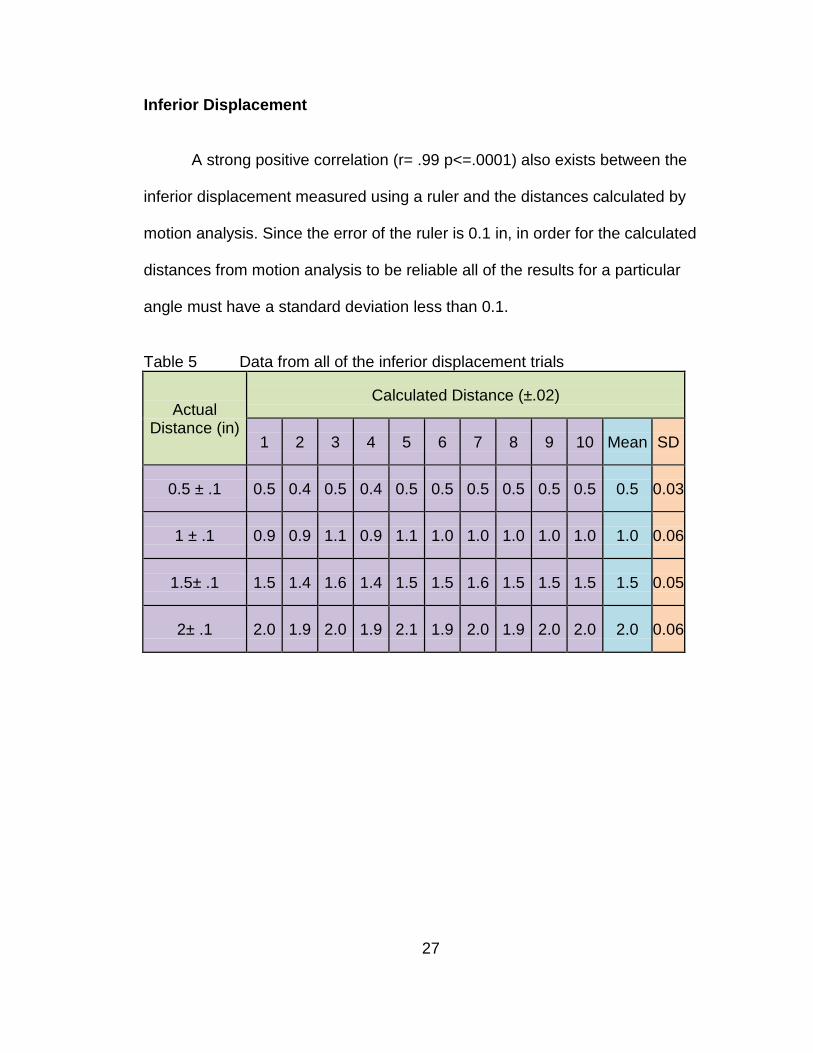
Inferior Displacement
A strong positive correlation (r= .99 p<=.0001) also exists between the
inferior displacement measured using a ruler and the distances calculated by
motion analysis. Since the error of the ruler is 0.1 in, in order for the calculated
distances from motion analysis to be reliable all of the results for a particular
angle must have a standard deviation less than 0.1.
Table 5 Data from all of the inferior displacement trials
Actual Distance (in)
Calculated Distance (±.02)
1 2 3 4 5 6 7 8 9 10 Mean SD
0.5 ± .1 0.5 0.4 0.5 0.4 0.5 0.5 0.5 0.5 0.5 0.5 0.5 0.03
1 ± .1 0.9 0.9 1.1 0.9 1.1 1.0 1.0 1.0 1.0 1.0 1.0 0.06
1.5± .1 1.5 1.4 1.6 1.4 1.5 1.5 1.6 1.5 1.5 1.5 1.5 0.05
2± .1 2.0 1.9 2.0 1.9 2.1 1.9 2.0 1.9 2.0 2.0 2.0 0.06

28
Figure 14 Regression Analysis between the accepted displacement values and the VICON calculated distances. The error bars represent ± SEM.
y = 1.0026x - 0.0101R² = 0.9998
0.000
0.500
1.000
1.500
2.000
2.500
0 1 2 3
Calc
ulat
ed D
ista
nce
(in)
Actual Distance (in)
Actual vs. Mean Calculated Distances

29
Medial/Lateral Tilt
A strong positive correlation (r=. 99 p<.0001) between the actual or
accepted value for tilt and the VICON calculated angles for tilt of the socket on
the residual limb. The error on the protractor is 1 degree therefore the difference
between the two standard deviations should be less than 1 degree.
Table 6 Data from all of the tilt trials Protractor Tilt (deg)
VICON calculated tilt (deg) 1 2 3 4 5 6 7 8 9 10 average SD
5 ± 2 5.0 5.3 4.8 4.9 6.0 5.7 4.8 5.5 5.2 6.3 5.4 0.5 10 ± 2 9.5 10.0 10.6 9.4 10.4 10.2 9.7 10.3 10.3 9.9 10.0 0.4
Figure 15 Regression Analysis between the accepted tilt angle and the VICON calculated distances. The error bars represent ± SEM
y = 0.9343x + 0.6811R² = 1
0.0
5.0
10.0
15.0
0.0 2.0 4.0 6.0 8.0 10.0 12.0VIC
ON
cal
cula
ted
tilt
(deg
)
Actual tilt measurements (deg)
Actual Vs. Mean VICON calculated tilt values

30
Axial Rotation
A strong positive correlation (r=. 99 p<.0001) between the actual or
accepted value for axial rotation and the VICON calculated angles for tilt of the
socket on the residual limb. The error on the protractor is 1 degree therefore the
difference between the two standard deviations should be less than 1 degree.
Figure 16 Regression Analysis between the accepted axial rotation angle and the VICON calculated distances. The error bars represent ± SEM

31
Shoulder Angle Verification
The calculations for the shoulder angles were the same for both the
validated marker set and the experimental marker set.
Figure 17 Comparison between the validated marker set and the experimental marker set during shoulder flexion
Figure 18 Comparison between the validated marker set and the experimental marker set during shoulder abduction
-20
0
20
40
60
80
100
Calc
ulat
ed A
ngle
(Deg
)
Time
Shoulder Angle Calculations during Flexion
Validate Marker Set
Experimental Marker Set
0
20
40
60
80
Calc
ulat
ed A
ngle
(Deg
)
Time (sec)
Shoulder Angle Calculations during Abduction
Validated Marker Set
Experimental Marker Set

32
CHAPTER 4-DISCUSSION, LIMITATIONS AND RECOMMENDATIONS FOR FUTURE WORK
As mentioned in the introduction the analysis of upper extremity motion is
still considered to be at an early stage. [10, 11] This study will add to the current
research of upper extremity motion by starting the conversation about how to
quantify the motion at the S-RL interface. It is imperative to keep in mind that
this is just a preliminary study and limited to laboratory studies at this time.
The ability to quantify the motion at the S-RL interface will improve studies
involving tranhumeral prostheses, socket design, and socket fit. The
biomechanical model discussed in this paper is able to provide both valid and
reliable measurements for the motion at the residual limb. Not only will this
provide an objective way to quantify fit but also provide some insight as to how
much motion provides the stability and control required without causing too much
skin irritation that the patient chooses not to wear the prosthesis.
The most obvious limitation is the lack of any human subjects in the study.
However, it is imperative to at least test the concept of the model before going
through the long process of getting IRB approval and finding subjects for the test.
Also due to the fact that the model was not tested on humans the experimental
marker set has only been shown to be reliable and valid on a rigid body residual

33
model. Despite this fact this study has shown that it is possible to get valid and
reliable measurements of the motion at the S-RL interface using motion analysis.
Other limitations include using only one trim line and one residual limb
length. However, as mentioned above, as long as the ResLC and ScktC are still
aligned the trim line will not affect the results. In terms on residual limb length,
issues would arise if the residual limb was very short or if the amputation
occurred at the shoulder joint. Depending on the size of the markers and the
resolution of the cameras there may not be enough room to separate the residual
limb and socket into two different segments. Another limitation is that I did not
take into consideration properties of skin.
In order to quantify accepted values for the motion at the S-RL limb
interface human subject testing needs to occur. The use of an electronic
goniometer would provide an easier way to collect the accepted values of the
motion rather than trying to attach both a goniometer and protractor to the
individual. Also since this method is only practical in a laboratory setting it is
important to try to create a tool that is more user friendly for a clinical setting.
Another aspect not considered in this study is the correlation between the she
forces created by the motion which is what causes the skin irritation and sores on
the residual limb. In order to study the forces and pressure caused by the
motion, sensors would need to be added to measure the amount of force and
pressure.
The ability to measure the motion and forces at the S-RL interface is very
important to the study of prosthetics. This will help researchers not only

34
understand how and why skin irritation can and does occur on the residual limb
but also help them determine how much motion is necessary to create the
perfect balance between control and skin irritation.

35
REFERENCES
1. Shultz, AE, Baade, SP, and Kuiken, TA, Expert Opinion on success factors for upper-limb prostheses. Journal of Rehabilitation Research and Development, 2007. 44(4): p. 8.
2. Nielson, C, Survey of amputees:functional level and life satisfaction,
information needs, and the prosthetist's role. Journal of Prosthetics and Orthotics, 1990. 3: p. 5.
3. Alley, RD, Biomechanical Discussion of Current and Emergent Upper-
Limb Prosthetic Interface Design. The Academy Today, 2009(June): p. 6. 4. Jia, X, Zhang, M, and Lee, WC, Load transfer mechanics between trans-
tibial prosthetic socket and residual limb--dynamic effects. J Biomech, 2004. 37(9): p. 1371-7.
5. Sensinger, JW and Weir, RF, Modeling and preliminary testing socket-
residual limb interface stiffness of above-elbow prostheses. IEEE Trans Neural Syst Rehabil Eng, 2008. 16(2): p. 184-90.
6. Andrews, J, Transhumeral and Elbow Disarticulation Anatomically
Contoured Socket Considerations. American Academy of Orthotists and Prosthetists, 2008. 20(3): p. 5.
7. Daly, W, Upper extremity socket design options. Phys Med Rehabil Clin N
Am, 2000. 11(3): p. 627-38. 8. Lake, C, The Evolution of Upper Limb Prosthetic Socket Design. American
Academy of Orthotists and Prosthetists, 2008. 20(3): p. 8. 9. Lee, WC and Zhang, M, Using computational simulation to aid in the
prediction of socket fit: a preliminary study. Med Eng Phys, 2007. 29(8): p. 923-9.
10. Anglin, C and Wyss, UP, Review of arm motion analyses. Proc Inst Mech
Eng H, 2000. 214(5): p. 541-55.

36
11. Drummey, J, Enhancing the Functional Envelope: A Review of Upper-Limb Prosthetic Treatment Modalities. The Academy Today, 2009. June: p. 5.
12. Gironda, RJ, Lloyd, J, Clark, ME, and Walker, RL, Preliminary evaluation
of reliability and criterion validity of Actiwatch-Score. J Rehabil Res Dev, 2007. 44(2): p. 223-30.
13. Small, CF, Bryant, JT, Dwosh, IL, Griffiths, PM, Pichora, DR, et al.,
Validation of a 3D optoelectronic motion analysis system for the wrist joint. Clin Biomech (Bristol, Avon), 1996. 11(8): p. 481-483.
14. Lowe, B, Accuracy and validity of observational estimated of shoulder and
elbow posture. Applied Ergonomics, 2004. 35: p. 13. 15. Carey, SL, Jason Highsmith, M, Maitland, ME, and Dubey, RV,
Compensatory movements of transradial prosthesis users during common tasks. Clin Biomech (Bristol, Avon), 2008. 23(9): p. 1128-35.
16. Stein, RB and Walley, M, Functional comparison of upper extremity
amputees using myoelectric and conventional prostheses. Arch Phys Med Rehabil, 1983. 64(6): p. 243-8.
17. Weekes, DL, Wallace, SA, and Anderson, DI, Training with an upper-limb
prosthetic simulaor to enhance transfer of skills across limbs. Arch. Phys. Med. Rehabilitation, 2003. 843: p. 7.
18. Highsmith, MJ, Carey, SL, Koelsch, KW, Lusk, CP, and Kinematic
evaluation of terminal devices for kayaing with upper extremity amputation. Journal of Prosthetics and Orthotics, 2007. 19(84): p. 7.
19. Craig, JJ, Introduction to Robotics Mechanics and Contol Third ed. 2005,
Upper Saddle River: Pearson Education, Inc.

37
APPENDICES

38
Appendix A : Marker File !MKR#2 [Autolabel] C7 Cervical level 7 T10 Thoracic level 10 CLAV Clavicle STRN Sternum RBAK Right back assymetrical marker RSHO Right shoulder WrstM Wrist thumb side WrstL Wrist pinkie side UPA Upper arm ELBM ELBL LSHO Left shoulder MWComp Medial LWComp Left wrist pinkie side ECompL Lateral point on elbow component ECompM Medial Point on elbow component BRESL Back point on res limb FRESL Front point on res limb RSckt Right (medial) point on socket FSckt Left (lateral) point on socket sLSJC simulated LSJC (for rig) LSJC left shoulder joint center CLAV,STRN,C7,T10,RBAK BRESL,FRESL,LSHO RSckt,FSckt,ECompL,ECompM RSHO,RUPA,RELB LWComp,MWComp,ECompL,ECompM ElbM,RWRA,RWRB Torso = C7,T10,CLAV,STRN,RBAK LShoulder = LSHO,CLAV,T1

39
Appendix A (Continued)
ResLimb = BRESL,FRESL,sLSJC Socket = RSckt,FSckt,ECompL,ECompM LForearm = LWRA,LWRB,ECompL,ECompM RShoulder = RSHO,CLAV,T10 RUpperarm = RSHO,RUPA,RELB RForearm = RELB,RWRA,RWRB Torso,RShoulder Torso,LShoulder RShoulder,RUpperarm RUpperarm,RForearm LShoulder,ResLimb Socket,LForearm [Segment Axes] ORIGINTorso AXISXTorso AXISYTorso AXISZTorso ORIGINTorso,AXISXTorso ORIGINTorso,AXISYTorso ORIGINTorso,AXISZTorso ORIGINRUpperarm AXISXRUpperarm AXISYRUpperarm AXISZRUpperarm ORIGINRUpperarm,AXISXRUpperarm ORIGINRUpperarm,AXISYRUpperarm ORIGINRUpperarm,AXISZRUpperarm ORIGINResLimb AXISXResLimb AXISYResLimb AXISZResLimb ORIGINResLimb,AXISXResLimb ORIGINResLimb,AXISYResLimb ORIGINResLimb,AXISZResLimb

40
Appendix A (Continued)
ORIGINSocket AXISXSocket AXISYSocket AXISZSocket ORIGINSocket,AXISXSocket ORIGINSocket,AXISYSocket ORIGINSocket,AXISZSocket ORIGINRForearm AXISXRForearm AXISYRForearm AXISZRForearm ORIGINRForearm,AXISXRForearm ORIGINRForearm,AXISYRForearm ORIGINRForearm,AXISZRForearm ORIGINLForearm AXISXLForearm AXISYLForearm AXISZLForearm ORIGINLForearm,AXISXLForearm ORIGINLForearm,AXISYLForearm ORIGINLForearm,AXISZLForearm ORIGINRWrist AXISXRWrist AXISYRWrist AXISZRWrist ORIGINRWrist,AXISXRWrist ORIGINRWrist,AXISYRWrist ORIGINRWrist,AXISZRWrist ORIGINLWrist AXISXLWrist AXISYLWrist AXISZLWrist ORIGINLWrist,AXISXLWrist ORIGINLWrist,AXISYLWrist ORIGINLWrist,AXISZLWrist ORIGINGlobal AXISXGlobalAXISY GlobalAXISZGlobal

41
Appendix A (Continued) ORIGINGlobal,AXISXGlobal ORIGINGlobal,AXISYGlobal ORIGINGlobal,AXISZGlobal [Joint centers] RSJC LSJC REJC ECompC ScktC ResLC WrstJC WCompJC [Angles] LShoulderAngles ResLScktAngles ElbowCompAngles RShoulderAngles ElbowAngles [Distances] DistResLSocket

42
Appendix B : Vicon BodyBuilder Program for Rig Note: new part highlighted. {*---------------------------------------------------------------------------------*} {* Biomechanical Model Of Transhumeral Prosthesis *} {* Rebekah Freilich 2009 *} {* Master Thesis for Biomedical Engineering *} {* University of South Florida *} {*----------------------------------------------------------------------------------*} {*------------------------------*} {*Start of Macro Section*} {*-------------------------------*} {*Display of Segment Axis*} {*---------------------------------*} Macro AXISVISUALISATION(Segment) ORIGIN#Segment=O(Segment) AXISX#Segment={100,0,0}*Segment AXISY#Segment={0,100,0}*Segment AXISZ#Segment={0,0,100}*Segment output(ORIGIN#Segment,AXISX#Segment,AXISY#Segment,AXISZ#Segment) ENDMACRO {*--------------------*} {*End of Macro Section*} {*--------------------*} {*Define Global Origin*} {*--------------------*} Gorigin = {0,0,0} Global = [Gorigin,{1,0,0},{0,0,1},xyz] {*----------------------------*}

43
Appendix B (Continued) {*Definition of Virtual Points*} {*----------------------------*} {*Torso*} {*-----*} {* BTorso= (C7+T10)/2 LTorso = (T10+STRN)/2 FTorso = (CLAV+STRN)/2 UTorso = (C7+CLAV)/2 *} {*Shoulder*} {*--------*} {* {*Temporary local coordinate system*} TempRClav = [RSHO,C7-RSHO,1(Torso),zyx] TempLClav = [LSHO,C7-LSHO,1(Torso),zyx] {* If $Static == 1 Then RSJC = RSHO+{0,0,-$RShoulderDepth}*Attitude(Torso) LSJC = LSHO+{0,0,-$LShoulderDepth}*Attitude(Torso) $%RSJC = RSJC/TempRClav $%LSJC = LSJC/TempLClav PARAM($%RSJC) PARAM($%LSJC) EndIf *} {*From local coordinate system to global*} RSJC = $%RSJC*TempRClav LSJC = $%LSJC*TempLClav *} {*Elbow Component*} {*---------------*} ECompC = (ECompL+ECompM)/2

44
Appendix B (Continued) {*Wrist*} {*-----*} {*RWJC=(RWRA+RWRB)/2*} LWJC = (LWRA+LWRB)/2 {*Residual Limb*} {*-------------*} ResLC = (BResL+FResL)/2 {*Prosthetic Socket*} {*-----------------*} ScktC = (BSckt+FSckt)/2 {*-------------------------------*} {*Definition of Segments*} {*-------------------------------*} {* Torso = [UTorso,UTorso-LTorso,BTorso-UTorso,zyx] *} ResLimb = [ResLC,sLSJC-ResLC,BResL-FResL,zyx] Socket = [ECompC,ScktC-ECompC,ECompC-LWJC,zyx] {*RUpperm = [REJC,RSJC-REJC,REJC-RWJC,zyx] RForearm = [RWJC,REJC-RWJC,REJC-RSJC,zxy]*} LForearm = [LWJC,ECompC-LWJC,ECompC-sLSJC,zxy] {*RWrist = [RWJC,REJC-RWJC,RWRA-RWRB,zxy]*} LWrist = [LWJC,ECompC-LWJC,LWRA-LWRB,zxy]

45
Appendix B (Continued) {*------*} {*Angles*} {*------*} {*TorsoAngles = -<Global,Torso,xyz> *} {*LShoulderAngles = <Torso,ResLimb,yxz>(-2) RShoulderAngles = <Torso,RUpperarm,yxz>*} ResLScktAngles = <ResLimb,Socket,yxz> ElbowCompAngles = <Socket,LForearm,yxz> {*RElbowAngles = <RUpperarm,RForearm,yxz>*} {*---------*} {*Distances*} {*---------*} DistResLSocket = DIST(ECompL,FResL) {*------*} {*Output*} {*------*} {*Joint Centers*} OUTPUT (ECompC,ScktC,ResLC,LWJC) {*Angles*} OUTPUT (ElbowCompAngles) OUTPUT (ResFScktAngles) {*Distances*} OUTPUT (DistResLSocket)

46
Appendix B (Continued) {*DISPLAY*} {*This calls up the macro to display the segments*} AXISVISUALISATION(Socket) AXISVISUALISATION(ResLimb) AXISVISUALISATION(LForearm) AXISVISUALISATION(LWrist) AXISVISUALISATION(Global)

47
Appendix C: Vicon BodyBuilder Program Note: new part highlighted. {*------------------------------------------------------------------------------------*} {* Biomechanical Model Of Transhumeral Prosthesis *} {* Rebekah Freilich 2009 *} {* Master Thesis for Biomedical Engineering *} {* University of South Florida *} {*------------------------------------------------------------------------------------*} {*----------------------*} {*Start of Macro Section*} {*----------------------*} {*Display of Segment Axis*} {*-----------------------*} Macro AXISVISUALISATION(Segment) ORIGIN#Segment=O(Segment) AXISX#Segment={100,0,0}*Segment AXISY#Segment={0,100,0}*Segment AXISZ#Segment={0,0,100}*Segment output(ORIGIN#Segment,AXISX#Segment,AXISY#Segment,AXISZ#Segment) ENDMACRO {*--------------------*} {*End of Macro Section*} {*--------------------*} {*Define Global Origin*} {*--------------------*} Gorigin = {0,0,0} Global = [Gorigin,{1,0,0},{0,0,1},xyz]

48
Appendix C (Continued) {*----------------------------*} {*Definition of Virtual Points*} {*----------------------------*} {*Torso*} {*-----*} BTorso= (C7+T10)/2 LTorso = (T10+STRN)/2 FTorso = (CLAV+STRN)/2 UTorso = (C7+CLAV)/2 Torso = [UTorso,UTorso-LTorso,BTorso-UTorso,zyx] {*Shoulder*} {*--------*} {*Temporary local coordinate system*} {*TempRClav = [RSHO,C7-RSHO,1(Torso),zyx]*} TempLClav = [LSHO,C7-LSHO,1(Torso),zyx] IF Static==1 Then {*RSJC = RSHO+{0,0,-$RShoulderDepth}*Attitude(Torso)*} LSJC = LSHO+{0,0,-$LShoulderDepth}*Attitude(Torso) {*$%RSJC = RSJC/TempRClav*} $%LSJC = LSJC/TempLClav {*PARAM($%RSJC)*} PARAM($%LSJC) End {*From local coordinate system to global*} {*RSJC = $%RSJC*TempRClav*} LSJC = $%LSJC*TempLClav

49
Appendix C (Continued) {*Elbow Component*} {*---------------*} ECompC = (ECompL+ECompM)/2 {*Wrist*} {*-----*} {*RWJC=(RWRA+RWRB)/2*} LWJC = (LWRA+LWRB)/2 {*Residual Limb*} {*-------------*} ResLC = (RResL+LResL)/2 {*Prosthetic Socket*} {*-----------------*} ScktC = (RSckt+LSckt)/2 {*----------------------*} {*Definition of Segments*} {*----------------------*} Torso = [UTorso,UTorso-LTorso,BTorso-UTorso,zyx] ResLimb = [ResLC,LSJC-ResLC,RResL-LResL,zyx] Socket = [ECompC,ScktC-ECompC,ECompC-LWJC,zyx] {*RUpperm = [REJC,RSJC-REJC,REJC-RWJC,zyx] RForearm = [RWJC,REJC-RWJC,REJC-RSJC,zxy]*} LForearm = [LWJC,ECompC-LWJC,ECompC-LSJC,zyx]

50
Appendix C (Continued) {*RWrist = [RWJC,REJC-RWJC,RWRA-RWRB,zxy]*} LWrist = [LWJC,ECompC-LWJC,LWRA-LWRB,zxy] {*------*} {*Angles*} {*------*} TorsoAngles = -<Global,Torso,xyz> LShoulderAngles =<Torso,ResLimb,yxz>(-2) {*RShoulderAngles =<Torso,RUpperarm,yxz>*} ResLScktAngles =<ResLimb,Socket,yxz> ElbowCompAngles =<Socket,LForearm,yxz> {*RElbowAngles =<RUpperarm,RForearm,yxz>*} {*---------*} {*Distances*} {*---------*} DistResLS = DIST(ECompL,LResL) {*------*} {*Output*} {*------*} {*Joint Centers*} OUTPUT(ECompC,ScktC,ResLC,LWJC,LSJC) {*Angles*} OUTPUT(ElbowCompAngles) OUTPUT(ResLScktAngles)

51
Appendix C (Continued) {*Distances*} OUTPUT(DistResLS) {*DISPLAY*} {*This calls up the macro to display the segments*} AXISVISUALISATION(Socket) AXISVISUALISATION(ResLimb) AXISVISUALISATION(LForearm) AXISVISUALISATION(LWrist) AXISVISUALISATION(Global)