quantification of transhumeral prosthetic socket residual
TRANSCRIPT
University of South FloridaScholar Commons
Graduate Theses and Dissertations Graduate School
January 2014
Quantification of Transhumeral Prosthetic SocketResidual Limb Interface Movement Using MotionCapture and a Slip Detection SensorMatthew WernkeUniversity of South Florida, [email protected]
Follow this and additional works at: http://scholarcommons.usf.edu/etd
Part of the Biomedical Engineering and Bioengineering Commons, and the MechanicalEngineering Commons
This Dissertation is brought to you for free and open access by the Graduate School at Scholar Commons. It has been accepted for inclusion inGraduate Theses and Dissertations by an authorized administrator of Scholar Commons. For more information, please [email protected].
Scholar Commons CitationWernke, Matthew, "Quantification of Transhumeral Prosthetic Socket Residual Limb Interface Movement Using Motion Capture anda Slip Detection Sensor" (2014). Graduate Theses and Dissertations.http://scholarcommons.usf.edu/etd/4961
Quantification of Transhumeral Prosthetic Socket Residual Limb Interface
Movement Using Motion Capture and a Slip Detection Sensor
by
Matthew Michael Wernke
A dissertation submitted in partial fulfillment
of the requirements for the degree of
Doctor of Philosophy
Department of Chemical and Biomedical Engineering
College of Engineering
University of South Florida
Major Professor: Rajiv Dubey, Ph.D.
Stephanie Carey, Ph.D.
Samuel Phillips, Ph.D.
Jason Highsmith, Ph.D.
William Lee, Ph.D.
Mark Jarowzeski, Ph.D.
Date of Approval:
November 19, 2013
Keywords: Socket Fit, Socket Interface, Socket Slip, Socket Rotation, Body-Powered
Copyright © 2013, Matthew Michael Wernke

DEDICATION
I dedicate this dissertation to my parents, Michael and Debbie, and my sisters, Stephanie and
Rachel. Without their constant love and support, I would not have been able to finish this
dissertation.

ACKNOWLEDGMENTS
I would like to thank the hard work of so many people that made this dissertation possible.
Thank you to my committee members Dr. Rajiv Dubey, Dr. Stephanie Carey, Dr. Samuel
Phillips, Dr. William Lee, Dr. Mark Jaroszeski, and Dr. Jason Highsmith. Your guidance
throughout my years at the University of South Florida helped me become a better engineer and
researcher, and taught me how to challenge ideas and think more critically. I greatly appreciate
the various opportunities that were provided to me such as traveling to conferences to present my
work, exposure to a variety of research projects spanning all types of rehabilitation, and clinical
experience through work at the Veterans Hospital and private clinics.
I must also acknowledge the hard work of my fellow researchers at the Rehabilitation
Robotics and Prosthetics Testbed. I cannot thank my fellow graduate and undergraduate
researchers enough for the time and effort you extended to me during data collection and
processing. A special thank you goes to Dr. Derek Lura, a fellow doctoral student in lab, whom I
was able to learn a lot from as he completed his dissertation, knowledge that helped me complete
mine. A special thank you goes to Kasey Marquardt for the constant love, support, and positive
attitude as I finished this dissertation.

i
TABLE OF CONTENTS
LIST OF TABLES ..................................................................................................................... iv
LIST OF FIGURES .................................................................................................................... v
ABSTRACT ............................................................................................................................... x
CHAPTER 1: INTRODUCTION ................................................................................................ 1
1.1 Epidemiology and Need ............................................................................................. 2
1.2 Prosthesis Socket Design ........................................................................................... 5
1.3 Prosthesis Socket Fabrication ..................................................................................... 7
1.4 Prosthesis Suspension Methods .................................................................................. 9
1.4.1 Harness Suspension ..................................................................................... 9
1.4.2 Anatomic Suspending ................................................................................ 10
1.4.3 Pin-Lock Suspension ................................................................................. 11
1.4.4 Vacuum or Suction Suspension ................................................................. 12
1.4.5 Osseointegration ........................................................................................ 13
1.5 Previous Socket Interface Research .......................................................................... 15
1.5.1 Socket Effects on Soft Tissues ................................................................... 15
1.5.2 Motion Analysis Studies ............................................................................ 16
1.5.3 Pressure Mapping and Finite Element Modeling ........................................ 18
1.5.4 Radiological, Acoustic, Optical, and Other Methods .................................. 19
1.6 Gap in Knowledge ................................................................................................... 20
CHAPTER 2: DEVELOPMENT OF THE KINEMATIC MODEL ........................................... 22
2.1 Motion Analysis Model ........................................................................................... 22
2.2 Segment Definitions ................................................................................................ 27
2.2.1 Torso ......................................................................................................... 27
2.2.2 Scapula...................................................................................................... 28
2.2.3 Contralateral Upper Arm ........................................................................... 29
2.2.4 Socket ....................................................................................................... 29
2.2.5 Residual Limb ........................................................................................... 30
2.2.6 Prosthetic Forearm .................................................................................... 31
2.3 Joint Angle, Socket Translation, and Socket Slip Calculations ................................. 32
CHAPTER 3: DEVELOPMENT OF THE SLIP DETECTION SENSOR ................................. 36
3.1 Ballistic Gel Testing ................................................................................................ 36
3.2 Slip Detection Sensor ............................................................................................... 38
3.2.1 Hardware Development ............................................................................. 38

ii
3.2.2 Software Development .............................................................................. 43
3.2.3 Slip Detection Sensor Validation ............................................................... 44
CHAPTER 4: STUDY PROCEDURES AND DATA ANALYSIS ........................................... 48
4.1 First Collection Day Procedures ............................................................................... 49
4.1.1 Socket Duplication .................................................................................... 51
4.2 Second Collection Day Procedures .......................................................................... 57
4.3 Data Analysis .......................................................................................................... 59
4.3.1 TAPES Questionnaire Analysis ................................................................. 59
4.3.2 RoM Tasks Analysis ................................................................................. 60
4.3.3 ADL Tasks Analysis ................................................................................. 60
CHAPTER 5: RESULTS .......................................................................................................... 63
5.1 TAPES Questionnaire .............................................................................................. 63
5.2 Shoulder RoM ......................................................................................................... 63
5.3 Socket Movement During the ADL Tasks ................................................................ 66
CHAPTER 6: RESULTS ANALYSIS AND SOCKET DESIGN .............................................. 76
6.1 H01.......................................................................................................................... 77
6.2 H02.......................................................................................................................... 80
6.3 H03.......................................................................................................................... 85
6.4 H04/H05 .................................................................................................................. 89
6.5 H06.......................................................................................................................... 95
6.6 H07.......................................................................................................................... 98
CHAPTER 7: DISCUSSION AND LIMITATIONS ............................................................... 103
7.1 Review of Hypotheses ........................................................................................... 105
7.2 Comparison of Results to Other Socket Movement Studies .................................... 107
7.3 Clinical Impact ...................................................................................................... 108
7.4 Standardization of the Socket Fitting Procedures ................................................... 111
7.5 Limitations ............................................................................................................ 112
CHAPTER 8: CONTRIBUTIONS AND FUTURE WORK .................................................... 114
8.1 Contributions ......................................................................................................... 115
8.2 Future Work .......................................................................................................... 116
REFERENCES ....................................................................................................................... 118
APPENDICES ........................................................................................................................ 124
Appendix A: Data Collection Documents .................................................................... 125
A.1 Subject Measurement Form ....................................................................... 125
A.2 Day 1 Data Collection Checklist ................................................................ 126
A.3 Day 2 Data Collection Checklist ................................................................ 127
A.4 Trinity Amputation and Prosthesis Experience Scales (TAPES) ................ 128
Appendix B: Matlab Code ........................................................................................... 135
B.1 SRiM.m ..................................................................................................... 135

iii
B.2 SRiM\Subfunctions\removewhite.m .......................................................... 154
B.3 SRiM\Subfunctions\WMAfilter.m ............................................................. 155
B.4 SRiM\Subfunctions\createSegment.m ........................................................ 155
B.5 SRiM\Subfunctions\FindTheta.m ............................................................... 157
B.6 SRiM\Subfunctions\addPointe2.m ............................................................. 161
B.7 SRiM\Subfunctions\clusterReconstruct.m .................................................. 161
B.8 SkinMotion.m ............................................................................................ 162
B.9 SkinMotion\Subfunctions\maximize.m ...................................................... 163
B.10 SkinMotion\Subfunctions\myclosereq.m.................................................. 167
B.11 SkinMotion\Subfunctions\gpos.m ............................................................ 167
B.12 SkinMotion\Subfunctions\windowMaximize.m ....................................... 169

iv
LIST OF TABLES
Table 1: Marker placement descriptions .................................................................................... 26
Table 2: Virtual marker descriptions.......................................................................................... 27
Table 3: Participants’ measurements and prosthesis/socket characteristics ................................. 49
Table 4: First testing day RoM task descriptions ....................................................................... 50
Table 5: Second testing day RoM task descriptions ................................................................... 57
Table 6: Functional task descriptions ......................................................................................... 58
Table 7: Results of the TAPES questionnaire for all of the participants ..................................... 63
Table 8: Results of the multivariate linear regression ................................................................. 75
Table 9: Summary of comparison to other socket studies......................................................... 108

v
LIST OF FIGURES
Figure 1: Survey results reproduced from [4] .............................................................................. 4
Figure 2: Types of prosthetic socket movement ........................................................................... 6
Figure 3: Traditional socket fabrication process........................................................................... 8
Figure 4: Figures 8 harness suspension system .......................................................................... 10
Figure 5: Pin locking suspension ............................................................................................... 12
Figure 6: Vacuum assisted socket with valve ............................................................................. 13
Figure 7: Illustration of direct bone attachment.......................................................................... 14
Figure 8: Marker set used in a previous study ............................................................................ 23
Figure 9: Difference in RoM calculated using the proximal and distal residual limb
markers of one above-elbow amputee. ..................................................................... 24
Figure 10: Difference in residual limb bone approximation using socket markers versus
new method ............................................................................................................. 25
Figure 11: Calculation of the center of residual limb bone inside the socket volume .................. 26
Figure 12: Diagram of the torso frame relative to markers ......................................................... 28
Figure 13: Diagram of the scapula frame relative to markers ..................................................... 28
Figure 14: Diagram of sound upper arm frame relative to markers ............................................ 29
Figure 15: Diagram of socket frame relative to markers ............................................................ 30
Figure 16: Diagram of residual limb frame relative to markers .................................................. 31
Figure 17: Diagram of forearm frame relative to markers .......................................................... 31
Figure 18: Ballistic gel simulation of residual limb .................................................................... 36

vi
Figure 19: Results of ballistics gel simulation: Red arrow indicates area of possible slip ........... 37
Figure 20: Left: Pen mouse; Right: Sensor and circuit board ..................................................... 39
Figure 21: SolidWorks assembly of first prototype slip detection sensor casing ......................... 39
Figure 22: SolidWorks assembly of second prototype slip detection casing ............................... 40
Figure 23: SolidWorks assembly of third prototype slip detection sensor casing ........................ 41
Figure 24: SolidWorks assembly of final slip detection sensor insert used in the study .............. 42
Figure 25: Root mean square error of vertical slip from the initial comparison of the
Slip Detection Sensor to the motion capture system ................................................. 45
Figure 26: The sensor cuff and Slip Detection Sensor being used to compare the
sensor’s output to the motion analysis system data ................................................... 46
Figure 27: Flowchart of participation in the study...................................................................... 49
Figure 28: Process for making the positive mold representing the internal socket shape. ........... 52
Figure 29: Plaster mold with a suction valve is placed upside down on the vacuum rig. ............. 53
Figure 30: Left: Sheet of thermoplastic; Right: Pan with hole to allow for droop of
thermoplastic ........................................................................................................... 53
Figure 31: Oven used to heat the thermoplastic and drooping of the thermoplastic at two
different time periods ............................................................................................... 54
Figure 32: Forming the thermoplastic over the plaster mold, and removal of the excess
material.................................................................................................................... 55
Figure 33: A: E400 45 mm prefabricated elbow and forearm, B: Quick disconnect wrist
assembly, C: Hosmer hook 5XA, D: Quick Disconnect insert .................................. 56
Figure 34: Shoulder flexion results from the RoM tasks for the study sample ............................ 64
Figure 35: Shoulder abduction results from the RoM tasks for the study sample ........................ 64
Figure 36: Shoulder rotation results from the RoM tasks for the study sample ........................... 65
Figure 37: Average anterior-posterior socket tilt for the study sample ....................................... 67
Figure 38: Average medial-lateral socket tilt for the study sample ............................................. 67

vii
Figure 39: Average vertical socket translation for the study sample ........................................... 68
Figure 40: Average vertical socket slip for the study sample...................................................... 68
Figure 41: Average rotational socket slip for the study sample .................................................. 69
Figure 42: Linear regression plot correlating anterior-posterior socket tilt to task weight ........... 70
Figure 43: Linear regression plot correlating medial-lateral socket tilt to task weight ................ 70
Figure 44: Linear regression plot correlating vertical socket translation to task weight .............. 71
Figure 45: Linear regression plot correlating vertical socket slip to task weight ......................... 71
Figure 46: Linear regression plot correlating rotational socket slip to task weight ...................... 72
Figure 47: Linear regression plot correlating anterior-posterior socket tilt to residual
limb RoM during the task ........................................................................................ 72
Figure 48: Linear regression plot correlating anterior-posterior socket tilt to residual
limb RoM during the task ........................................................................................ 73
Figure 49: Linear regression plot correlating vertical socket translation to residual
limb RoM during the task ........................................................................................ 73
Figure 50: Linear regression plot correlating vertical socket slip to residual limb RoM
during the task ......................................................................................................... 74
Figure 51: Linear regression plot correlating rotational socket slip to residual limb
RoM during the task ................................................................................................ 74
Figure 52: Linear regression for H01 correlating anterior-posterior socket tilt RoM
and residual limb RoM for both prostheses .............................................................. 78
Figure 53: Linear regression for H01 correlating medial-lateral socket tilt RoM and
residual limb RoM for both prostheses ..................................................................... 78
Figure 54: Linear regression for H01 correlating socket vertical translation RoM and
residual limb RoM for both prostheses ..................................................................... 79
Figure 55: Linear regression for H01 correlating socket slip RoM and the weight of
each task for the sensor embedded prosthesis ........................................................... 79
Figure 56: Linear regression for H02 correlating anterior-posterior socket tilt RoM and
residual limb RoM for both prostheses ..................................................................... 81

viii
Figure 57: Linear regression for H02 correlating medial-lateral socket tilt RoM and
residual limb RoM for both prostheses ..................................................................... 82
Figure 58: Linear regression for H02 correlating socket vertical translation RoM and
residual limb RoM for both prostheses ..................................................................... 82
Figure 59: Linear regression for H02 correlating socket slip RoM and the weight of
each task for the sensor embedded prostheses .......................................................... 83
Figure 60: Linear regression for H03 correlating anterior-posterior socket tilt RoM and
residual limb RoM for both prostheses ..................................................................... 86
Figure 61: Linear regression for H03 correlating medial-lateral socket tilt RoM and
residual limb RoM for both prostheses ..................................................................... 86
Figure 62: Linear regression for H03 correlating vertical socket translation RoM and
residual limb RoM for both prostheses ..................................................................... 87
Figure 63: Linear regression for H03 correlating socket slip RoM and weight of each
task for the sensor embedded prostheses .................................................................. 87
Figure 64: H04/H05 anterior-posterior socket tilt for the original prosthesis with and
without using the pin-locking system ....................................................................... 90
Figure 65: H04/H05 medial-lateral socket tilt for the original prosthesis with and
without using the pin-locking system ....................................................................... 90
Figure 66: H04/H05 proximal-distal translation for the original prosthesis with and
without using the pin-locking system ....................................................................... 91
Figure 67: Vertical slip for the sensor embedded prosthesis using the two suspension
systems .................................................................................................................... 91
Figure 68: Rotational slip for the sensor embedded prosthesis using the two suspension
systems .................................................................................................................... 92
Figure 69: Linear regression for H04/H05 correlating anterior-posterior socket tilt
RoM and residual limb RoM for the original prostheses with and without
pin-locking suspension ............................................................................................. 93
Figure 70: Linear regression for H04/H05 correlating medial-lateral socket tilt RoM
and residual limb RoM for the original prostheses with and without pin-
locking suspension ................................................................................................... 93

ix
Figure 71: Linear regression for H04/H05 correlating vertical socket translation RoM
and residual limb RoM for the original prostheses with and without pin-
locking suspension ................................................................................................... 94
Figure 72: Linear regression for H04/H05 correlating vertical and rotational slip RoM
and the weight of each task for the sensor embedded prostheses with and
without pin-locking suspension ................................................................................ 94
Figure 73: Linear regression for H06 correlating anterior-posterior socket tilt RoM
and residual limb RoM for both prostheses .............................................................. 96
Figure 74: Linear regression for H06 correlating medial-lateral socket tilt RoM and
residual limb RoM for both prostheses ..................................................................... 96
Figure 75: Linear regression for H06 correlating vertical socket translation RoM and
residual limb RoM for both prostheses ..................................................................... 97
Figure 76: Linear regression for H06 correlating socket slip RoM and the weight of each
task for the sensor embedded prostheses .................................................................. 98
Figure 77: Linear regression for H07 correlating anterior-posterior socket tilt RoM
and residual limb RoM for both prostheses ............................................................ 100
Figure 78: Linear regression for H07 correlating medial-lateral socket tilt RoM and
residual limb RoM for both prostheses ................................................................... 100
Figure 79: Linear regression for H07 correlating vertical socket translation tilt RoM
and residual limb RoM for both prostheses ............................................................ 101
Figure 80: Linear regression for H07 correlating socket slip RoM and the weight of
each task for the sensor embedded prostheses ........................................................ 101

x
ABSTRACT
Current literature focusing on the prosthetic socket is limited by measurement techniques and
modeling assumptions, leading to a limited understanding of the forces and motions occurring
between the residual limb and prosthesis and how they can be used to influence socket design
and fitting. Prosthetic socket fitting and prescription would benefit from an elegant method for
comparing socket designs. This dissertation focuses on the development and implementation of a
3D motion capture model and a Slip Detection Sensor to quantify rotations and translations at the
prosthetic socket-residual limb interface. The 3D motion capture model defines the residual limb
bone position inside the prosthetic socket which allows for measurement of the movement
occurring at the prosthetic socket interface. The Slip Detection Sensor is an optoelectronic sensor
embedded into the prosthetic socket wall to measure the amount of socket slip occurring between
the socket wall and the residual limb skin surface. The motion capture model and Slip Detection
Sensor were used to measure motion at the socket interface of transhumeral amputees during
activities of daily living. Data were collected on six transhumeral amputees in the University of
South Florida’s (USF) motion analysis laboratory. One of the participants completed the
collection procedures twice using two different suspension systems (pin locking versus no pin
locking) within the same socket.
An eight camera Vicon (Oxord, UK) motion capture system was used to collect kinematic
data for each participant during the repetition of a series of range of motion (RoM) and activities
of daily living (ADL). The RoM tasks included shoulder flexion/extension, shoulder

xi
abduction/adduction, shoulder rotation, and elbow flexion. The ADL tasks included a bilateral
and unilateral lifting task at various weight increments, modified box and blocks test, folding a
towel, and walk and carry a gallon jug of water. The impact of donning the prosthesis on the
participant’s RoM and the amount of socket movement during the ADL tasks was analyzed.
The results show that the participant’s shoulder RoM significantly decreased while wearing
their prosthesis compared to when they were not wearing their prosthesis. The anterior-posterior
tilt, medial-lateral tilt, and socket vertical translation were more directly correlated with the
amount of residual limb movement than with the force acting on the prosthetic hand. Socket slip
was most directly correlated with the force acting on the prosthetic hand. The results also show
that the amount of translation was reduced when the pin locking suspension was used compared
to when it wasn’t for the individual participant who used both suspension systems within the
same socket.
The motion capture data were used to determine the amount of socket movement during
activities of daily living while avoiding many of the limitations of other socket interface studies.
The Slip Detection Sensor provided experimental data on the amount of slip occurring between
the residual limb skin surface and socket wall. This method seems to be a useful tool for
evaluating socket performance in terms of movement. Ultimately, socket interface movement
data can be used to providing clinicians with quantitative results of a good socket fit to aid in the
socket fitting and prescription process and incorporated into adjustable interfaces. Collection of
data on more participants with various socket types is needed to make more general conclusions.

1
CHAPTER 1: INTRODUCTION
The objective of this dissertation was to develop a method to measure prosthetic socket
interface movement and use that method to quantify movement occurring at the socket and
residual limb interface of transhumeral prostheses. A Vicon optical motion capture system was
used to track upper body and prosthesis segments during common tasks and an optoelectronic
sensor (Patent Pending, 61/727,249) designed by the author provided experimental data on the
amount of socket slip occurring between the inner socket wall and residual limb skin surface.
These systems were chosen because it does not limit the participant to static poses or interfere
with the internal volume of the socket. The following hypotheses were defined:
1) There will be a significant decrease in residual limb shoulder range of motion (RoM)
while wearing a prosthesis compared to not wearing a prosthesis,
2) Participants with shorter residual limbs will have more socket movement than
participants with longer residual limbs,
3) The weight of the task performed will have the most significant impact on the amount of
movement occurring at the socket interface.
The goals of the research were to:
1) Develop a motion capture model to calculate residual limb bone position inside the
prosthetic socket,
2) Design, prototype, and validate a Slip Detection Sensor to measure the relative motion
between the socket and residual limb skin surface (socket slip),

2
3) Quantify the range of movement of the prosthetic socket relative to the residual limb
bone during activities of daily living (ADL) using the motion capture model and Slip
Detection Sensor,
4) Correlate the socket interface movement to various outcomes and define possible fit
parameters,
5) Make suggestions on how a prosthetist could use the data during the socket fitting and
prescription procedures.
Gaining a better understanding of how a socket moves relative to the skeletal features of the
residual limb can lead to more comfortable sockets, greater transmission of forces between user
and device, result in fewer socket related skin issues, and provide quantitative measures of a
movement efficient socket fit to aid socket prescription and fitting.
1.1 Epidemiology and Need
Upper limb prostheses are used to replace the function and appearance of the missing portion
of their arm. Prostheses are composed of several components, including the socket, which serves
as the connection between the human and the prosthesis. The purpose of the socket is to capture
movements of the intrinsic skeletal features of the residual limb and transfer these motions to
other parts of the prosthesis. Capturing the motions of the intrinsic skeleton is complicated by
soft tissues which allow motion to occur between the human skeleton and the prosthesis as a
result of compression and deformation of the soft tissues (i.e. skin, fat, and musculature) as well
as slip. The soft tissues are not intended to be mechanical load bearers, and these motions and
forces can have damaging effects on the soft tissues [1, 2] and possibly diminish the efficacy of
the prosthesis. Furthermore, residual limbs experience volume fluctuations due to environmental
and biological factors, creating an ever-changing socket interface that could increase the amount

3
of rotation, translation, and slip of the socket. Few methods exist to quantify socket rotations and
translation, and even fewer exist to measure socket slip.
Despite the recognized importance of the prosthetic socket [3-5], little research focusing on
socket interface motion has been conducted. The research that has been completed focuses on the
prosthetic socket interface and outcomes are hardly conclusive due to the limitations of the
testing procedures and equipment used. Additionally, research literature focusing on upper limb
prosthetic sockets is noticeably less prevalent than lower limb literature.
It is estimated that the number of individuals with a limb amputation in the United States will
increase to 2.2 million by 2020 [6]. Data obtained during a 5 year period from 2001 to 2006 by
the Joint Theater Trauma Registry and Military Amputee Research Program reported that 423
service members have suffered one or more limb amputations [7]. Of those, 105 had an upper
extremity amputation at a wrist disarticulation level or more proximal. In 2010, greater than 950
soldiers have sustained a combat related amputation in association with the wars in Iraq and
Afghanistan [8]. That number rose to 1599 in 2012 from all recent conflicts [9].
A survey of amputee prosthesis users found that socket interface comfort was rated the most
important factor over prosthetic weight, agility, power and appearance (Figure 1) [4]. Nearly one
third of amputees reported being dissatisfied with the comfort of their device while 18.4% of the
respondents reported being fit with a new prosthesis at least once a year according to one survey
[10]. This survey also showed that amputees see their prosthetist up to nine times a year.
A review over the past 25 years found that rejection rates among upper limb prosthesis users
were approximately one out of five individuals [11]. Rejection of prostheses can occur for a
number of reasons, some of which include level of amputation, type and usefulness of prosthesis,
poor training, excessive time between amputation and prosthetic fitting, and cost of repairs [12].

4
Figure 1: Survey results reproduced from [4]. Shows the importance of the socket interface rated by users.
Another study found that participants with lower limb amputations were significantly more
likely to wear a prosthesis and wear it for more hours per day that participants with upper limb
amputations [13]. A study comparing Vietnam veterans to veterans of Operation Iraqi
Freedom/Operation Enduring Freedom found that upper limb prosthesis users completely
abandoned their device 30% and 22% among the two groups respectively [14]. Additionally,
focusing on more proximal amputation levels such as transhumeral or shoulder disarticulation
find a higher rejection rate of 42% and 40% respectively for the two groups. These statistics
highlight the growing demand for upper and lower limb prostheses and indicate the current
dissatisfaction with the prosthetic socket among prosthesis users, particularly for upper extremity
amputations.
Evidence based research is becoming more valuable in the prosthetic industry. Upper limb
prostheses can range from $4,000 to $75,000+ depending on the control type and level of
5
amputation. Additionally, lifetime prosthetic costs for upper limb prosthesis users can range from
$100,000 to more than $1,990,000 depending on the type of prosthesis and if the patient is
unilateral or bilateral [15]. However, major insurers place financial caps on prosthetic coverage,
which can range from $10,000 to one prosthesis during an individual’s lifetime [16]. These limits
restrict the availability of prostheses and chances to be refit for a new socket. Private insurers
regularly categorize new prosthetic technologies as experimental [16], emphasizing the need for
evidence based research on these systems.
Prosthesis simulators are currently being developed to allow an amputee to “test-drive”
various prosthetic systems to provide evidence based recommendations to clinicians for
prosthetic prescription [17]. Expanding simulators to include the prosthetic socket and
suspension recommendations could increase the comfort and functional performance of
prostheses and decrease the number of visits to the prosthetist for socket related issues. Before
such a tool can be designed, a method to analyze the performance of various socket designs and
suspension methods is needed.
1.2 Prosthesis Socket Design
The socket couples human and prosthesis, and greatly impacts comfort and prosthetic
function. Ideally, the socket would transmit forces to and from the user with perfect efficiency,
transferring any movements of the residual limb bone without lost motion to the prosthetic limb.
However, because the soft tissues between the prosthetic socket and residual limb bone are not
rigid, external forces can cause compressions and deformations of the soft tissue. Therefore, only
a portion of the bone movement is transferred to the prosthesis. The socket can apply
compressive forces normal, fn, to the skin surface in localized areas, leading to rotation of the
socket relative to the residual limb bone (Figure 2B). These rotations occur about three axes,
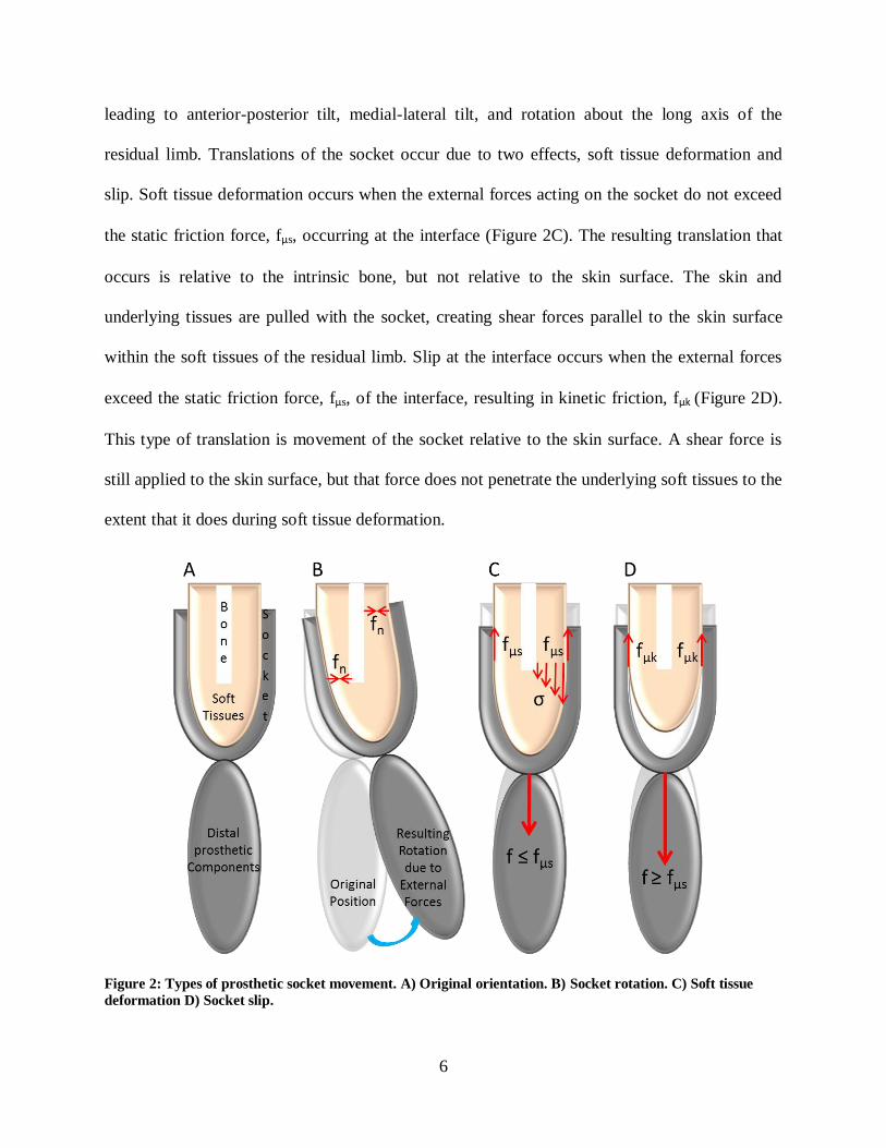
6
leading to anterior-posterior tilt, medial-lateral tilt, and rotation about the long axis of the
residual limb. Translations of the socket occur due to two effects, soft tissue deformation and
slip. Soft tissue deformation occurs when the external forces acting on the socket do not exceed
the static friction force, fμs, occurring at the interface (Figure 2C). The resulting translation that
occurs is relative to the intrinsic bone, but not relative to the skin surface. The skin and
underlying tissues are pulled with the socket, creating shear forces parallel to the skin surface
within the soft tissues of the residual limb. Slip at the interface occurs when the external forces
exceed the static friction force, fμs, of the interface, resulting in kinetic friction, fμk (Figure 2D).
This type of translation is movement of the socket relative to the skin surface. A shear force is
still applied to the skin surface, but that force does not penetrate the underlying soft tissues to the
extent that it does during soft tissue deformation.
Figure 2: Types of prosthetic socket movement. A) Original orientation. B) Socket rotation. C) Soft tissue
deformation D) Socket slip.

7
The art of designing a socket is to achieve a stable connection with the residual limb while
maintaining a comfortable fit that can be worn for long periods of time without causing damage
to the residual limb. In order to limit the amount of socket movement and provide a more
comfortable connection with the residual limb, every prosthetic socket is custom made for the
user.
1.3 Prosthesis Socket Fabrication
Traditional sockets are made by creating a series of positive and negative molds which are
used to form the socket shape. Fabrication commonly begins by wrapping the residual limb with
a plaster wrap casting. This negative mold is then filled with a plaster mixture to form a positive
mold representing the residual limb shape. The positive mold is then altered by the prosthetist,
who can make physical modifications by adding or removing plaster in order to decrease or
increase the pressure distribution in certain areas. Once an acceptable shape is achieved deemed
by the prosthetist’s experience, a clear thermoplastic socket is manufactured. For most sockets
(those other than an x-frame socket used for shoulder disarticulations), the blister forming
technique is used.
Once fabrication is complete, the amputee dons the socket and performs a static and dynamic
socket check which includes ambulating for lower limb devices, RoM, strength, and functional
assessment for upper limb devices. The prosthetist will monitor the blanching of the skin through
the clear socket wall during the dynamic socket check to identify areas that seem to have
excessive or insufficient soft tissue compression. Feedback from the amputee is also solicited to
determine socket modifications and adjustments that are needed. Based on the visual judgment of
the prothetist, feedback from the amputee, and past experiences, modifications are made to the
positive mold and another clear thermoplastic socket is manufactured. This process is repeated
8
until a final socket shape is reached, determined by the prosthetist. Sometimes a second check
socket is not needed and adjustments made to the first check socket are sufficient to make the
definitive socket. Then a final socket is made out of more permanent materials such as carbon
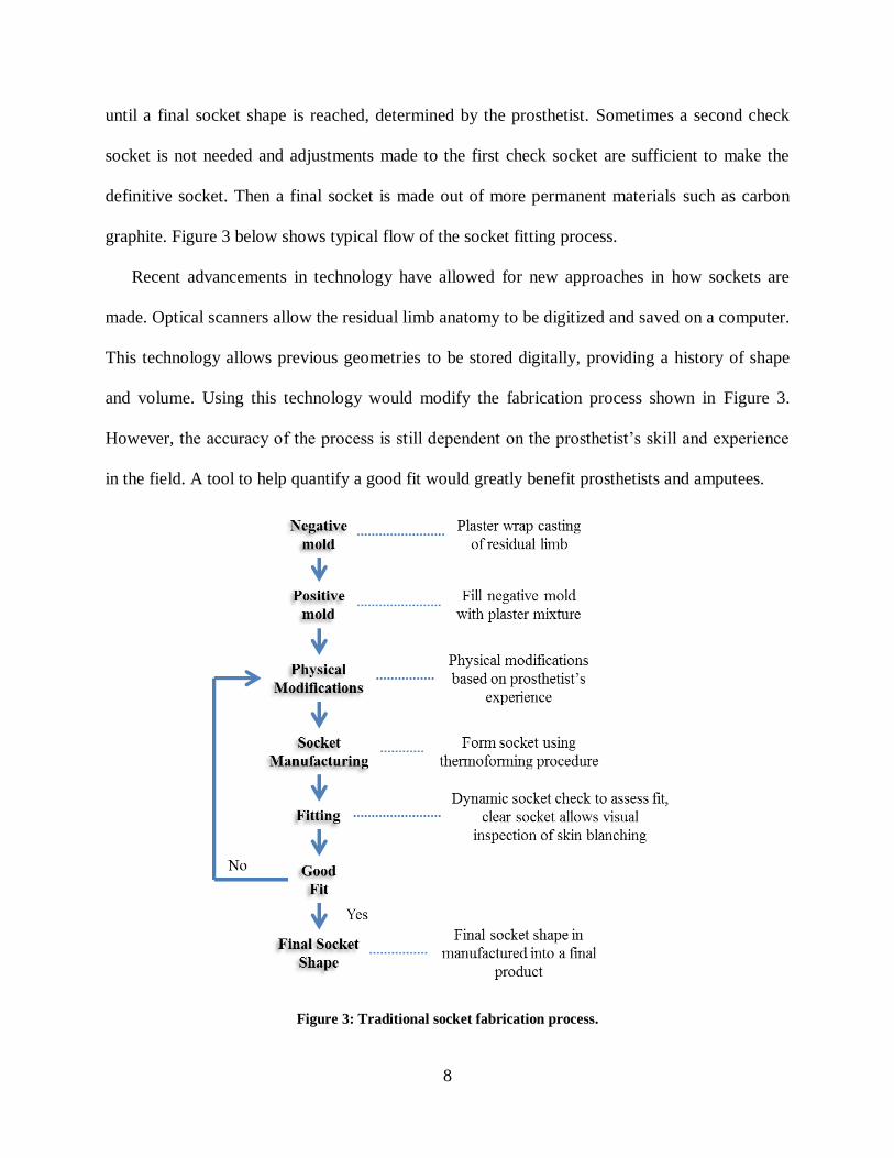
graphite. Figure 3 below shows typical flow of the socket fitting process.
Recent advancements in technology have allowed for new approaches in how sockets are
made. Optical scanners allow the residual limb anatomy to be digitized and saved on a computer.
This technology allows previous geometries to be stored digitally, providing a history of shape
and volume. Using this technology would modify the fabrication process shown in Figure 3.
However, the accuracy of the process is still dependent on the prosthetist’s skill and experience
in the field. A tool to help quantify a good fit would greatly benefit prosthetists and amputees.
Figure 3: Traditional socket fabrication process.
9
1.4 Prosthesis Suspension Methods
While the socket is the part of the prosthesis that contains the residual limb, the method of
suspension is the manner by which the prosthesis is attached to the limb. There are many options
available to the prosthetist for suspension, and the method chosen can affect the way the socket
is designed. The methods of suspension include harnessing, anatomic suspension, pin lock
systems, vacuum or suction assisted, and osseointegration.
1.4.1 Harness Suspension
Harnessing was one of the first suspension systems applied to upper limb prostheses. These
systems were developed and used as early as the 1950’s and have undergone minor changes
since then. The socket shape with these systems aims for gross encapsulation of the residual limb
and is suspended by a strap that can take different shapes. The shape and configuration of the
straps depends on factors such as level of amputation and whether or not the harness is for
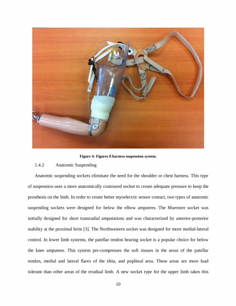
suspension and control or control only. The Figure-8 strap configuration [18] is commonly used
for suspension and fitted around the contralateral shoulder with a cross point in the back (Figure
4). Alternatives to the figure-8 strap are the chest strap [19]. This may provide a more
comfortable option to some users who find the figure-8 harness uncomfortable in the axilla
region and is more commonly used with shorter residual limb amputees. The harness system also
connects to the distal joints of the prosthesis and movements of the contralateral shoulder places
tension in the cables and allows the prosthetic joints to move. This type of control scheme is
commonly referred to as a body-powered prosthesis, and provides the user with proprioceptive
feedback of the position and velocity of prosthetic joints by relating them to position and
velocity of anatomical joints [20]. Proprioception can simply be described as the awareness of
one’s body position without the use of visual feedback.
10
Figure 4: Figures 8 harness suspension system.
1.4.2 Anatomic Suspending
Anatomic suspending sockets eliminate the need for the shoulder or chest harness. This type
of suspension uses a more anatomically contoured socket to create adequate pressure to keep the
prosthesis on the limb. In order to create better myoelectric sensor contact, two types of anatomic
suspending sockets were designed for below the elbow amputees. The Muenster socket was
initially designed for short transradial amputations and was characterized by anterior-posterior
stability at the proximal brim [3]. The Northwestern socket was designed for more medial-lateral
control. In lower limb systems, the patellar tendon bearing socket is a popular choice for below
the knee amputees. This system pre-compresses the soft tissues in the areas of the patellar
tendon, medial and lateral flares of the tibia, and popliteal area. These areas are more load
tolerant than other areas of the residual limb. A new socket type for the upper limb takes this
11
idea to an extreme. The high fidelity socket designed by Randall Alley consists of four struts
with concurrent areas of relief [21-23]. The four struts compress the soft tissues as much as
possible and attempt to minimize the delay between prosthetic movement and skeletal
movement. The concurrent windows cut out of the socket provide relief for the soft tissues
instead of confining them inside the socket volume. The creators of the high fidelity socket claim
the design has better osseosynchronization (connection to the bone) then traditional socket
techniques and limit motion between the user and prosthesis.
New suspension methods are constantly being developed, especially those designs that can
overcome the challenge of residual limb volume fluctuation. The Revo-Limb socket developed
by Boa Technology Inc. (Colorado, USA) is a dynamic interface that works by adjusting the
tightness of several panels of the socket [24]. The socket has a main shell with a number of
panels that fit into windows cut out of the shell. Wires run on the inside of the socket and
connect the main shell to the panels. The user can tighten or loosen the panels to create the
compression needed by turning a dial connected to the wires.
1.4.3 Pin-Lock Suspension
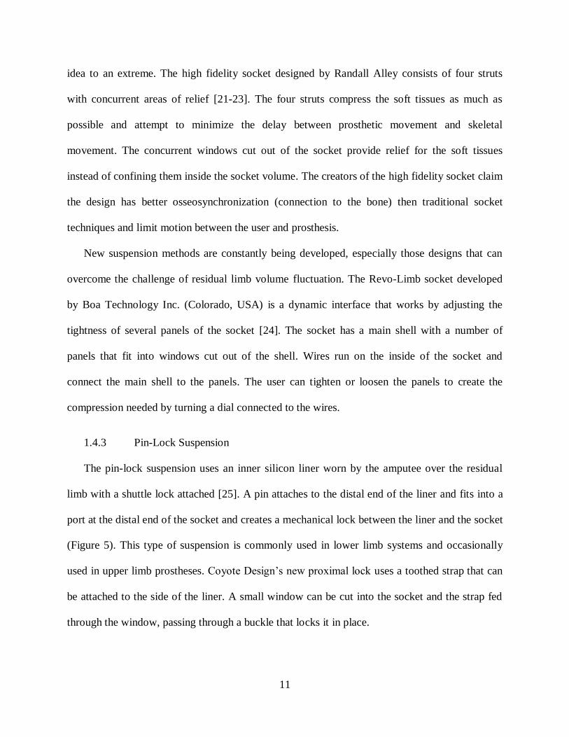
The pin-lock suspension uses an inner silicon liner worn by the amputee over the residual
limb with a shuttle lock attached [25]. A pin attaches to the distal end of the liner and fits into a
port at the distal end of the socket and creates a mechanical lock between the liner and the socket
(Figure 5). This type of suspension is commonly used in lower limb systems and occasionally
used in upper limb prostheses. Coyote Design’s new proximal lock uses a toothed strap that can
be attached to the side of the liner. A small window can be cut into the socket and the strap fed
through the window, passing through a buckle that locks it in place.

12
Figure 5: Pin locking suspension. A) Shuttle lock port at distal end of socket. B) Release button.
1.4.4 Vacuum or Suction Suspension
In vacuum systems, the socket creates a seal with the residual limb and a pump is used to
draw excess air out of the internal socket volume. This creates the vacuum suspension for the
limb. This type of suspension may have benefits for the residual limb such as a reduction in
residual limb volume change, but more research is needed to evaluate that hypothesis [26]. One
study compared a vacuum assisted suspension system to a pin locking suspension in lower limb
systems, and found that the amount of movement between the residual limb and socket
(pistoning) was less for the vacuum system [27]. However this study has been scrutinized for its
lack of details on how pistoning was measured as well as its testing procedures [28]. An alternate
method of suspension is the suction based suspension which is similar, but incorporates a liner
that has concurrent rings around it. As the socket is placed over the liner, the rings trap air and
create a suction force that provides suspension. These systems are often equipped with a valve
which allows the user to allow air back into the socket volume. This allows more comfort for
13
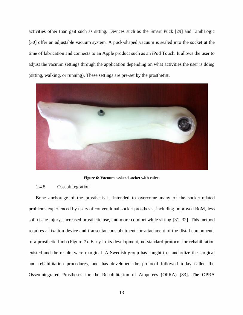
activities other than gait such as sitting. Devices such as the Smart Puck [29] and LimbLogic
[30] offer an adjustable vacuum system. A puck-shaped vacuum is sealed into the socket at the
time of fabrication and connects to an Apple product such as an iPod Touch. It allows the user to
adjust the vacuum settings through the application depending on what activities the user is doing
(sitting, walking, or running). These settings are pre-set by the prosthetist.
Figure 6: Vacuum assisted socket with valve.
1.4.5 Osseointegration
Bone anchorage of the prosthesis is intended to overcome many of the socket-related
problems experienced by users of conventional socket prosthesis, including improved RoM, less
soft tissue injury, increased prosthetic use, and more comfort while sitting [31, 32]. This method
requires a fixation device and transcutaneous abutment for attachment of the distal components
of a prosthetic limb (Figure 7). Early in its development, no standard protocol for rehabilitation
existed and the results were marginal. A Swedish group has sought to standardize the surgical
and rehabilitation procedures, and has developed the protocol followed today called the
Osseointegrated Prostheses for the Rehabilitation of Amputees (OPRA) [33]. The OPRA

14
procedure requires two surgical procedures, placed six months apart, in order to attach the
implant to the bone. The first surgery is required to attach the fixation device. During the period
between surgeries, the amputee may continue to use their traditional prosthesis while the area
around the fixation device heals from the first procedure. The second surgery attached the
transcutaneous abutment to the fixation device. The rehabilitation period post second surgery is
another 6 months as weight bearing has to be gradually increased to avoid loosening of the
implant. The implant is made from titanium as other attempts with non-titanium transcutaneous
metal implants have failed primarily due to infection [34]. While titanium appears to be
promising from the current literature, more research and long term studies are needed to
determine its effectiveness. One study prospectively followed 39 patients with arm and leg
amputations for a period of three years [34]. The most common bacteria were various forms of
Staphylococcus depending on if the sample was from superficial or deep tissues. More long term
studies following a formalized procedure such as the OPRA are needed to further analyze the
effects of osseointegration.
Figure 7: Illustration of direct bone attachment.

15
1.5 Previous Socket Interface Research
The premise behind the socket designs mentioned in the previous section is to distribute
socket forces about the residual limb, in order to create a stable and comfortable connection.
Many research projects focusing on the socket residual limb interface have been conducted to
better understand what forces the soft tissues can tolerate, what forces the soft tissues are
subjected to inside a prosthetic socket, and the magnitude of motion occurring at the socket
interface.
1.5.1 Socket Effects on Soft Tissues
The soft tissues of the residual limb are subjected to unfavorable conditions inside a
prosthetic socket. Forces from the socket are applied to the residual limb which is already
contained in a snug fitting socket. These forces can be pressure which occur perpendicular to the
skin surface, shear which occurs tangential to the skin surface, or friction which occurs when
shear is applied along with slip between the skin surface and socket. In addition to the socket
forces occurring inside the socket, the lack of air circulation inside the socket creates a hot and
humid environment and more vulnerable soft tissues. Excessive slip of the socket may result in
further heat generation. Additionally, materials chosen for the socket interface may create caustic
or allergic reactions for some users. All these factors make predicting soft tissue responses to
external forces difficult.
A few conclusions have been drawn from the current research. There exists an inverse
relationship between the intensity and duration of external forces until skin breakdown occurs.
These results have been found in a study utilizing a pig skin model [35] and others reviewed by
Mak [36] and Sanders [37]. The review by Mak also found that damage is greater when applied
to a localized area of the soft tissues, rather than distributed evenly. Pressure can also have an

16
effect on the soft tissues, leading to ischemia, or reduction in blood supply to tissues [38].
Improper blood supply reduces oxygen and glucose stores needed for cellular metabolism. The
review by Sanders stated that blisters are more likely to develop from friction forces. Skin has
been shown to be less tolerant of friction than shear forces [35]. When shear is applied to the soft
tissues, the force is distributed through a greater volume of tissue dispersing the stress
concentrations. When slip is applied, the friction force is distributed locally and increases the risk
of injury. Diabetic and dysvascular amputees are at an increased risk for skin breakdown [39].
The reviews by Mak and Sanders offer more information on this topic, which is outside the
scope of this dissertation. While these forces are needed for the suspension of a prosthesis,
excessive loading of the soft tissues can lead to unwanted effects like the ones discussed in this
section. It is important to understand when these two types of movement occur in order to
enhance residual limb health. Therefore several studies have quantified the relative motion or
pressure distribution inside the socket to better understand socket interface interactions, in hopes
of developing better sockets.
1.5.2 Motion Analysis Studies
A number of motion analysis studies have been conducted to analyze a variety of outcomes.
Knee and ankle kinetics have been analyzed during normal stair ambulation [40] and various
amounts of ankle dorsiflexion during stair ambulation[41] for unilateral amputees. Gait
mechanics has also been evaluated for bilateral amputees during gait [42, 43]. Compensatory
motions have also been evaluated for lower limb prosthesis users during normal gait [44], gait
with socket misalignments [45], and upper limb prosthesis users [46] during activities of daily
living (ADL). The control of a prosthetic knee has also been evaluated with and without early
walking rehabilitation [47]. One study compared kinetics of a prosthetic knee measured

17
experimentally to kinetics of various inverse dynamics calculations for transfemoral amputees
[48]. The safety of various prosthetic knees has also been evaluated during gait [49]. All of these
studies considered the kinematics and/or kinetics of prosthetic function under the assumption that
the socket interface was a rigid connection. One study sought to understand how errors in
anthropometric data affected kinetic calculations during gait for partial foot amputees [50]. The
residual foot and prosthesis were treated as separate segments in order to calculate a more
accurate center of mass and mass moment of inertia. It was found that this method yielded an
increased peak joint moment and power for the hip and knee. The study still considered the
socket-residual limb interface to have a rigid connection. However this interface is not a rigid
connection as shown by a previous study at the University of South Florida analyzing a kayaking
terminal device for upper limb prosthesis users. The study found a varying elbow angle for the
above-elbow user even though the elbow component of the device was locked at 40° [51]. The
authors suggest that part of this motion occurred at the socket interface.
One study used motion analysis to investigate movement at the socket interface by defining
the residual limb and socket as separate segments [52]. This technique was used on a transtibial
prosthesis user to measure the difference in pistoning when using two different liner types. This
marker set only measured motion in one direction and could not differentiate between socket
translations where the soft tissue deformation occurred and when slip between the socket and
skin surface occurred. A recent study at the University of South Florida developed an optical
marker set that could track the residual limb and prosthetic socket separately, allowing multi-
axial motion between the two segments to be captured [53].
18
1.5.3 Pressure Mapping and Finite Element Modeling
Several other studies have used pressure mapping systems and force transducer
measurements of internal socket pressures and compared the results to finite element models.
These studies sought to gain a better understanding of the pressure distribution inside the socket
with a goal of improving socket design and fitting. The studies are almost exclusively focused on
lower limb prosthesis [54-59]. The finite element models from the lower limb studies could be
divided into three main modeling methodologies. The first group modeled the interface such that
socket slip, separation between elements of the socket and residual limb, was not permitted [57,
58]. A second group modeled the interface the same way as the first, however during post
processing of the data, detected elements under tension and removed those forces [56].The last
main methodology allowed slip at the interface to be permitted [54, 55, 59]. All of the studies
mentioned above sought to build models to predict the interface stresses occurring. However
differences in modeling the elemental properties and boundary conditions, the type of pressure
transducer used and its placement, and the activity or task performed make inter-study
comparisons difficult. Additionally, placing a pressure mapping system inside the socket may
alter the user’s normal fit and thus affect results. Transducers like those used by Sanders et al
require sections of the socket wall to be removed in order for the sensor to work [57]. The results
of the slip permitted modeling methodology were not confirmed experimentally, because no
method existed to measure the amount of slip occurring at the interface.
One study analyzed an upper limb prosthesis using a pressure mapping system and found the
location of peak pressures varied depending on arm position [60]. Analysis of the pressure
mapping results on the residual limb indicates that the socket seemed to rotate about the center
length of residual limb bone. Lighter pressures were found around the middle of the residual

19
limb while higher pressures were at the proximal and distal portions of the residual limb. This
study highlights the increased variance of socket pressures of upper limb socket with respect to
lower limb. While the peak pressures in lower limb systems are also dependent on the position of
the limb, gait is the typical motion of the lower extremities and is a more cyclic pattern.
1.5.4 Radiological, Acoustic, Optical, and Other Methods
Other studies have used radiological [61-65], acoustic [66], and optical [67] methods to
analyze the movement of the residual limb bone inside the socket for lower limb systems. The
radiological studies primarily analyzed tibia movement inside a socket referred to as pistoning,
or the up and down movement of the residual limb relative to the socket. A range of pistoning
was found from 22 to 75 mm. One study looked at slip using lead markers placed on the skin and
socket liner [68]. The study found the amount of slip increased from 2 mm to 6 mm when an
additional 133.5 N of load was applied in the axial direction while the total distal translation was
10 mm for the tibia. Only one study analyzed the rotational stiffness of an upper limb socket
using a radiological method [69]. This study found the rotational stiffness of the interface could
be modulated through contractions of the residual limb musculature. This study also used the
center point of the length of bone inside the socket as the rotation center for the socket. However,
due to the limited viewing window of the measurement device, testing protocols were limited to
imitating phases of gait in static positions or only allowing for one step.
In order to analyze gait, Convery designed a mountable ultrasound system to monitor bone
movement inside the socket [66]. The RoM of the intrinsic bone relative to the socket was 12.2°
for medial lateral socket tilt and 17.4° for anterior-posterior socket during gait. This method
required bulky equipment to be mounted to the socket wall, which may have been intrusive to
the participant.

20
An optical sensor mounted to the underside of a participant’s socket was used to track the
amount of pistoning of the socket during gait [67]. An average of 41.7 mm of pistoning was
found. The optical sensor used only recorded movement in one direction and thus could not
differentiate between socket translations that resulted in shear forces and those that resulted in
frictional forces on the residual limb.
Slip has also been measured using a pen rigidly attached to the well-fit total contact suction
socket [70]. The pen left an ink trail on the skin surface that could be analyzed once the plug
holding the pen was removed. The results indicate that for the socket type tested, the slip was
less than 6 mm. The author acknowledged the high inaccuracy of analyzing the data and noted it
as a limitation. Additionally, the data from this method could not be analyzed in real time, and
would not be advantageous to use as a controller of a dynamic interface system.
1.6 Gap in Knowledge
The survey results [4, 10-16] highlight the importance of prosthetic fit and comfort to the
user and its impact on the success of the prosthesis. Unfortunately, the review of the current
literature shows an absence of conclusive research involving the socket interface movement,
particularly the interface of upper limb prosthesis users. The studies analyzing the socket
interface are limited by the testing procedures and equipment used, leading to limited results that
can be used to impact socket design and prescription. Prosthetists acknowledge that movement at
the socket interface occurs, but the extent to which that movement should be limited has not been
defined. Additionally, slip occurring at the interface between the prosthetic socket and residual
limb skin surface is not well understood, due to the limited methods for measurement.
This dissertation sought to fill some of these gaps in knowledge surrounding socket interface
movement. These include the amount of rotations, translations, and slip occurring during

21
dynamic activities of transhumeral prosthesis users. A new motion analysis method for
calculating the position of the residual limb inside the socket and a novel Slip Detection Sensor
were used to track the motions of upper limb prosthesis users during common tasks. This will
allow researchers to analyze the amount of socket movement without interfering with internal
socket volume or limiting the movement of the participant. Using a motion capture system will
also avoid the need to make multiple modeling assumptions as in the finite element modeling
methods, and permit researchers to look directly at the socket motion occurring. Additionally, the
Slip Detection Sensor designed to measure the amount of slip occurring between the internal
socket wall and residual limb skin surface or inner liner surface will provide experimental data
during dynamic activities. The results from these measurement methods may provide data that
researchers and clinicians can use to positively impact the socket design and prescription
procedures.

22
CHAPTER 2: DEVELOPMENT OF THE KINEMATIC MODEL
Motion analysis involves quantitatively evaluating the movement of bodies. For this study,
motion analysis was used to track the movement of the socket relative to the residual limb. Eight
infrared cameras tracked the position of passive reflective markers placed at specific locations on
the subject’s upper body. Each of the eight Vicon (Oxford, UK) cameras yields the 2D position
of each marker in the camera frame and the Vicon system uses triangulation to obtain the 3D
marker position based off the intersection of the projections from the camera frames into the lab
frame. The motion analysis system was chosen to capture movements at the socket interface
because it does not interfere with the internal volume of the socket, does not limit the motions of
the user, and comparable to other studies. The motion analysis marker set was developed after
collecting pilot data of one above elbow subject.
2.1 Motion Analysis Model
The model was adapted from the methods developed by Freilich [53], who used markers
(RSLA, RSLP, SCKTA, SCKTP) above and below the socket trim lines as shown in Figure 8.
The RSLA and RSLP markers were used to create a vector to the shoulder joint center defining
the residual limb segment and the SCKTA and SCKTP markers were used to create a vector to
the elbow markers defining the socket segment. Defining the segments as described above
allowed the rotation and translation about all axes to be captured. This marker set was used in a
study to validate a robotic human upper body model (RHBM) [17], and the results from this
study used as pilot data. Results from the pilot data showed that the intra-task rotation of the

23
socket about the residual limb was highly variant when using the RSLA and RSLP markers but
not highly variant when using the elbow markers on the prosthetic side. These results suggested
that the RSLA and RSLP markers would not be reliable to use in the study due to limited
distance between the shoulder and socket as well as soft tissue artifacts.
Figure 8: Marker set used in a previous study. RSLA and RSLP are used to define the residual limb position
while SCKTA and SCKTP are used to define the socket. Skeleton image taken from the public domain.
The pilot participant also completed RoM tasks without wearing a prosthesis. Two sets of
residual limb markers (RSLA and RSLP) were used; one set placed at a more proximal position
on the limb and the other at a more distal position as illustrated in Figure 9. This was performed
to analyze the accuracy of proximal residual limb markers, such as those required in the marker
set developed by Friedlich, to markers at a more distal location on the residual limb. Analysis of
the results highlights the difference between using the proximal and distal residual limb markers.
When defining the residual limb position using the distal residual limb marker pair, a greater
angle was found. Proximal markers were in close proximity to the shoulder markers due to the
24
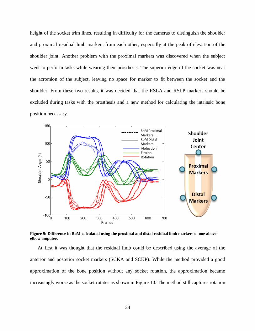
height of the socket trim lines, resulting in difficulty for the cameras to distinguish the shoulder
and proximal residual limb markers from each other, especially at the peak of elevation of the
shoulder joint. Another problem with the proximal markers was discovered when the subject
went to perform tasks while wearing their prosthesis. The superior edge of the socket was near
the acromion of the subject, leaving no space for marker to fit between the socket and the
shoulder. From these two results, it was decided that the RSLA and RSLP markers should be
excluded during tasks with the prosthesis and a new method for calculating the intrinsic bone
position necessary.
Figure 9: Difference in RoM calculated using the proximal and distal residual limb markers of one above-
elbow amputee.
At first it was thought that the residual limb could be described using the average of the
anterior and posterior socket markers (SCKA and SCKP). While the method provided a good
approximation of the bone position without any socket rotation, the approximation became
increasingly worse as the socket rotates as shown in Figure 10. The method still captures rotation

25
(angle between the red arrow and the green dotted line which projects the socket vector) but is
not accurate to the position of the intrinsic bone.
To improve the accuracy of the intrinsic bone position, the socket was assumed to rotate
about the center of the length of bone inside the socket, an assumption used in a previous study
of rotational stiffness in above elbow prostheses [69]. This point is the center of rotation and
remains in the center of the socket. The average of the anterior and posterior markers represents
the middle on the socket, and can be translated in the proximal-distal axis of the socket frame.
The amount the average socket marker position was translated and calculated based on the
marker set and subject measurements as illustrated in Figure 11.
Using this method, the residual limb position could be approximated and the amount of
rotation between the residual limb and socket calculated. Figure 10 shows the how the new
approximation of the residual limb position gives a more accurate angle between the residual
limb and socket. The final marker set used is described in Table 1.
Figure 10: Difference in residual limb bone approximation using socket markers versus new method.

26
Figure 11: Calculation of the center of residual limb bone inside the socket volume.
Table 1: Marker placement descriptions.
Name Placement
T1 Spinous process of 1st
thoracic vertebrae
T10 Spinous process of 10th
thoracic vertebrae
CLAV Jugular notch
STRN Xiphoid process
LBAK Left scapula (used for assymetry)
R/LASI Right/Left anterior superior iliac spine
R/LPSI Right/Left posterior superior iliac spine
R/LIC Right/Left iliac crest
R/LSHOA Right/Left anterior acromion
R/LSHOP Right/Left posterior acromion
R/LELB Right/Left lateral epicondyle
R/LELBM Right/Left medial epicondyle
R/LWRA Right/Left raial styloid
R/LWRB Right/Left ulnar styloid
R/LFIN Right/Left 3rd
metacarpal head (dorsal side)
SCKTA Anterior socket 10 cm from superior trim lines
SCKTP Posterior socket 10 cm from superior trim lines
27
2.2 Segment Definitions
The marker set described above is used to define the body segments of the upper body which
include the torso, scapula, upper arm, forearm, and hand. Note, the marker set included pelvis
markers; however a pelvis segment was not defined. The pelvis markers were used to help the
Vicon software label each trial, decreasing the post-processing time. The segments were created
in Matlab using a script called createSegment.m [17]. The script defined each segment using an
origin, two defining lines, and an order. The segments were centered at the origin. The first
defining line became the first axis. The cross product of the first and second defining lines
became the second axis. Finally the cross product between the first and second axis became the
third axis. The order given defines which axis corresponds to the X, Y, and Z axis. In order to
maintain the right hand rule, the direction of the third axis may be switched to the negative cross
product of the first and second axis if the right hand rule was not satisfied. A series of virtual
marker points were created in Matlab and were used in the segment definitions. These virtual
markers were created by taking the average of two markers and are described in Table 2 below.
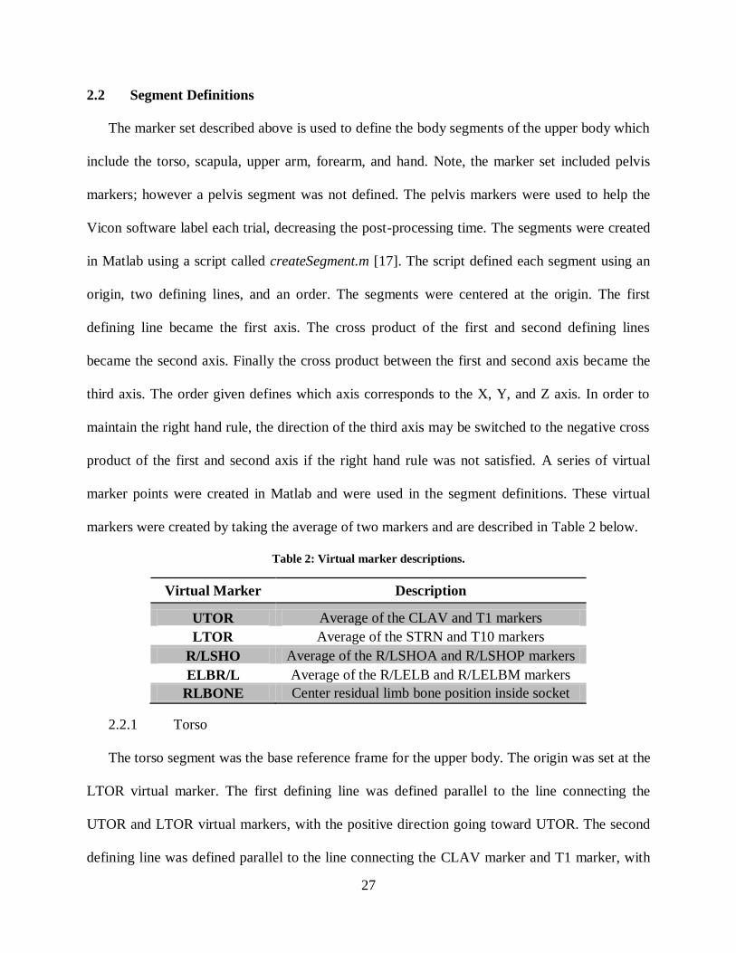
Table 2: Virtual marker descriptions.
Virtual Marker Description
UTOR Average of the CLAV and T1 markers
LTOR Average of the STRN and T10 markers
R/LSHO Average of the R/LSHOA and R/LSHOP markers
ELBR/L Average of the R/LELB and R/LELBM markers
RLBONE Center residual limb bone position inside socket
2.2.1 Torso
The torso segment was the base reference frame for the upper body. The origin was set at the
LTOR virtual marker. The first defining line was defined parallel to the line connecting the
UTOR and LTOR virtual markers, with the positive direction going toward UTOR. The second
defining line was defined parallel to the line connecting the CLAV marker and T1 marker, with

28
the positive direction pointing to the TI marker. The convention order used was ‘yzx’. Figure 12
shows the orientation of the torso frame relative to the markers.
Figure 12: Diagram of the torso frame relative to markers. Skeletal image taken from public domain.
2.2.2 Scapula
Connecting the torso and upper arm segments, the scapula segment approximates clavicle
and scapula movement, which is important to track, especially for body-powered prosthesis
users. Figure 13 shows the orientation of the scapula frame relative to the markers.
Figure 13: Diagram of the scapula frame relative to markers. Skeletal image taken from public domain.
The origin of the scapula was defined as the midpoint (RSHO/LSHO) between the RSHOA
and RSHOP markers for the right side and the LSHOA and LSHOP markers for the left side. The
first defining line was defined parallel to the line connecting the origin of the respective shoulder
and the UTOR position, with the positive direction going toward the shoulder. The second

29
defining line was the line connecting the posterior and anterior shoulder markers. The convention
order used was ‘zyx’.
2.2.3 Contralateral Upper Arm
The sound upper arm refers to the side of the subject that is not amputated. A different
segment definition is used for the residual limb. The origin of the sound upper arm was defined
as the R/LSHO points depending on the side of the body being described. The first defining line
is the line from the upper arm origin to the midpoint (ELBR/L) of the medial and lateral elbow
markers, with the positive direction going toward the shoulder. The second defining line was
defined parallel to the line connecting the lateral and medial elbow markers. The convention
order used was ‘yxz’. Figure 14 shows the orientation of the sound upper arm markers. Note, the
study was limited to unilateral amputees so only one side will be defined as the contralateral
upper arm, and the other will be defined as the residual limb described in Section 2.2.5.
Figure 14: Diagram of sound upper arm frame relative to markers. Both the right and left sound arm
definitions are shown, however, study participants had an amputation on one side. Skeletal image taken from
public domain.
2.2.4 Socket
The origin was set to the midpoint of the anterior and posterior socket markers. The first
defining line connected the origin to the midpoint of the lateral and medial elbow markers. The
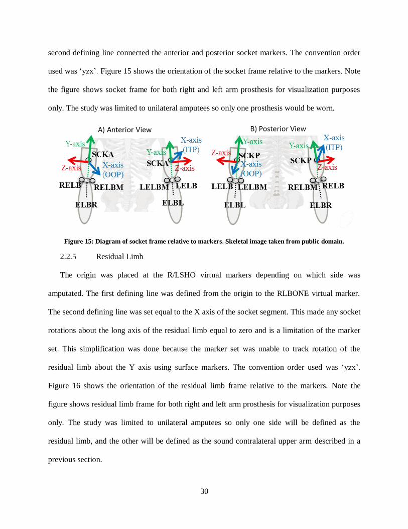
30
second defining line connected the anterior and posterior socket markers. The convention order
used was ‘yzx’. Figure 15 shows the orientation of the socket frame relative to the markers. Note
the figure shows socket frame for both right and left arm prosthesis for visualization purposes
only. The study was limited to unilateral amputees so only one prosthesis would be worn.
Figure 15: Diagram of socket frame relative to markers. Skeletal image taken from public domain.
2.2.5 Residual Limb
The origin was placed at the R/LSHO virtual markers depending on which side was
amputated. The first defining line was defined from the origin to the RLBONE virtual marker.
The second defining line was set equal to the X axis of the socket segment. This made any socket
rotations about the long axis of the residual limb equal to zero and is a limitation of the marker
set. This simplification was done because the marker set was unable to track rotation of the
residual limb about the Y axis using surface markers. The convention order used was ‘yzx’.
Figure 16 shows the orientation of the residual limb frame relative to the markers. Note the
figure shows residual limb frame for both right and left arm prosthesis for visualization purposes
only. The study was limited to unilateral amputees so only one side will be defined as the
residual limb, and the other will be defined as the sound contralateral upper arm described in a
previous section.

31
Figure 16: Diagram of residual limb frame relative to markers. Skeletal image taken from public domain.
2.2.6 Prosthetic Forearm
The origin was placed at the ELBR/L virtual markers depending on which side the
amputation was on. The first defining line was defined from the origin to the average of the wrist
markers (R/LWRA and R/LWRB). The second defining line was defined set equal to the Z axis
of the socket segment. This made any rotations besides flexion and extension between the socket
and the forearm equal to zero, limiting movement of the elbow angle to flexion and extension
only. This simplification was done because the prosthetic limbs did not allow forearm
pronation/supination. The convention order used was ‘yxz’. Figure 17 shows the orientation of
the forearm frame relative to the markers.
Figure 17: Diagram of forearm frame relative to markers. Skeletal image taken from public domain.

32
Note only the forearm segment for the prosthesis was defined so that the elbow angle at
which the prosthesis was holding objects during the ADL tasks could be used as a covariate for
statistical purposes. The coordinate frame definitions for each segment described above were
used to calculate the relative position and orientation of body segments.
2.3 Joint Angle, Socket Translation, and Socket Slip Calculations
The information needed to completely specify one coordinate system relative to another is
position and orientation. Position refers to the distance between the origin of one system to
another, measured along the X, Y, and Z axes of one of the systems. Orientation refers to the
angle(s) about which one system is rotated relative to the other. Robotics uses a set of four
vectors to describe this information in an entity called a frame. The term transformation matrix is
given to the 4 x 4 matrix representing a frame. These matrices (also called homogeneous
transform) describe a coordinate system relative to the laboratory coordinate system or to
another coordinate system. A generic homogeneous transform is shown in Equations 1 and
describes a frame A with respect to a laboratory frame L.
[
]
[
] (1)
The first three rows and three columns are known as the rotation matrix and describe the
segment’s relative orientation. The first cell, r11, describes the projection of the X axis of
coordinate system A onto the X axis of the laboratory coordinate system. Similarly, cell r32
describes the projection of the Y axis of coordinate system A onto the Z axis of the laboratory
coordinate system. For Euler Angles, describes later, a rotation order was specified for each of
the segments, which determined the order the rotation matrices were multiplied together. The
33
rotation orders were chosen to eliminate singularities in the data. Singularities refer to points in
which the mapping between two segments is no longer invertible. The terms px, py, and pz,
describe the position between the two systems.
All calculations were performed from the base script titled, SRiM.m, Appendix B.1. First, to
ensure the data filenames could be read in Matlab, the script removewhite.m (Appendix B.2)
removed spaces in the filenames. Next, a marker position reconstruct algorithm was used called
clusterReconstruct.m (Appendix B.7) and then filtered using a weight moving point average
(WMAfilter.m, Appendix B.3). A homogeneous transform was defined for each segment using
createSegment.m (Appendix B.4). The laboratory frame was defined during calibration of the
Vicon motion analysis system with the calibration wand, and was always set in the same position
and orientation on the floor of the lab. These homogeneous transforms were then used to
calculate the relative transformation matrices between two frames, for example the upper arm
relative to the scapula frame. This was accomplished by multiplying one homogenous transform
by the inverse of the other as shown in Equation 2 where the frame B was describe with respect
to frame A.
(2)
If frame A represented the scapula and frame B represented the upper arm, the results of the
above equation would yield the orientation and position of the upper arm frame relative to the
scapula frame. This operation was performed for the scapula relative to the torso, the upper arm
(or residual limb depending on amputated side) relative to the scapula, and the socket relative to
the residual limb.
The rotational order used was ‘zxy’ between the scapula and the torso. Rotation about the Z
axis describes the roll of the scapula or rotation about the sagittal axis. This rotation is positive

34
internally for the right scapula and negative for the left. Rotation about the X axis represents
depression of the scapula on both the right and left sides. Finally, rotation about the Y axis
signifies protraction of the scapula on the right and retraction on the left.
The rotational order between the upper arm and the scapula was ‘zxy’. Rotation about the Z
axis describes flexion or plane of elevation of the upper arm. Rotation about the X axis
represents abduction or elevation of the upper arm. Finally, rotation about the Y axis signifies
axial rotation of the upper arm. The rotation order used for the residual limb segment and the
motions these axis describe are the same as the sound upper arm segment.
The rotational order used was ‘zxy’ between the socket and the residual limb. Rotation about
the Z axis describes flexion or plane of elevation of the socket about the residual limb. Rotation
about the X axis represents abduction or elevation of the socket about the residual limb. Finally,
rotation about the Y axis signifies axial rotation of the socket about the residual limb.
The Euler rotation angles were then calculated once the transformation matrices were
computed using findTheta.m (Appendix B.5) using the rotation order defined for each segment.
In this notation, each rotation is performed about a moving axis rather than a fixed one, therefore
the axis of rotation is dependent upon the preceding rotation. The rotation angles are derived
from certain cells of the transformation matrix.
( √ ) (3)
(
) (4)
(
) (5)
Euler angles were computed for all of the trials and used for comparison of the magnitude of
rotation of the socket. An alternate method for describing the rotation was also used for the
residual limb. This alternate method made it more clear the extent of which the residual limb was
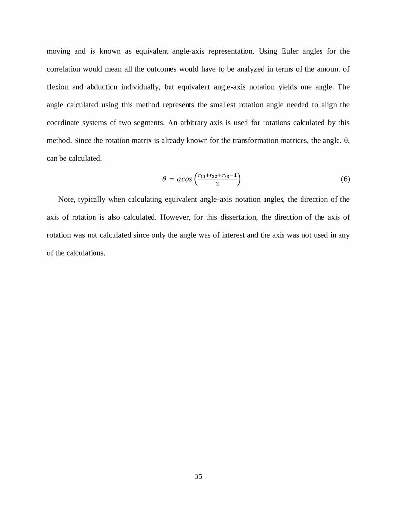
35
moving and is known as equivalent angle-axis representation. Using Euler angles for the
correlation would mean all the outcomes would have to be analyzed in terms of the amount of
flexion and abduction individually, but equivalent angle-axis notation yields one angle. The
angle calculated using this method represents the smallest rotation angle needed to align the
coordinate systems of two segments. An arbitrary axis is used for rotations calculated by this
method. Since the rotation matrix is already known for the transformation matrices, the angle, θ,
can be calculated.
(
) (6)
Note, typically when calculating equivalent angle-axis notation angles, the direction of the
axis of rotation is also calculated. However, for this dissertation, the direction of the axis of
rotation was not calculated since only the angle was of interest and the axis was not used in any
of the calculations.
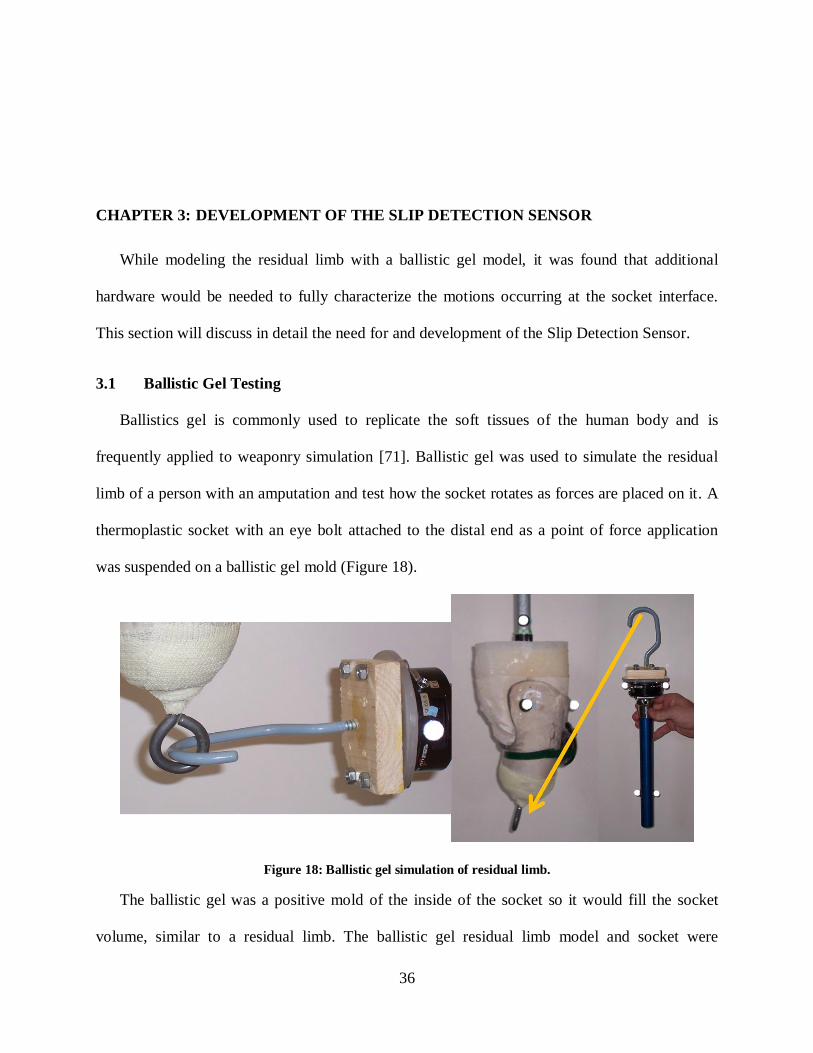
36
CHAPTER 3: DEVELOPMENT OF THE SLIP DETECTION SENSOR
While modeling the residual limb with a ballistic gel model, it was found that additional
hardware would be needed to fully characterize the motions occurring at the socket interface.
This section will discuss in detail the need for and development of the Slip Detection Sensor.
3.1 Ballistic Gel Testing
Ballistics gel is commonly used to replicate the soft tissues of the human body and is
frequently applied to weaponry simulation [71]. Ballistic gel was used to simulate the residual
limb of a person with an amputation and test how the socket rotates as forces are placed on it. A
thermoplastic socket with an eye bolt attached to the distal end as a point of force application
was suspended on a ballistic gel mold (Figure 18).
Figure 18: Ballistic gel simulation of residual limb.
The ballistic gel was a positive mold of the inside of the socket so it would fill the socket
volume, similar to a residual limb. The ballistic gel residual limb model and socket were

37
suspended from a wooden frame and a force applicator was used to apply forces to the socket. A
force transducer on the force applicator recorded the forces placed on the socket. A Vicon
motion analysis system tracked the amount of movement between the socket and residual limb
model. Note markers on the force applicator tracked the orientation so the direction of force
application was known.
The results were used to show that the rotation could be tracked by the Vicon system during
dynamic movement and that the movement at the interface could be modeled based on the force
placed on the system (Figure 19). Two models were used to describe the soft tissues; one based
off the non-linear form of Hooke’s Law and a second biaxial model that related the stresses and
strains on the system. Both models showed good results but the biaxial model was more
computationally efficient.
Figure 19: Results of ballistics gel simulation: Red arrow indicates area of possible slip. Black line should
return to zero.
After further review of the results, it was noticed the amount of rotation predicted by both
models returned to the starting point as the force exerted was removed. However, this was not
the case for the amount of rotation measured by the Vicon motion cameras. The error was
attributed to slip between the socket and simulated residual limb. Slip motion of the socket will

38
cause more hysteresis in the position of the socket relative to the residual limb and is important
to track. The Vicon system can detect this type of motion, but combines slip translation with
translation caused by soft tissue deformation. Therefore it was determined that an additional
sensor was necessary to measure when slip occurred between the socket and skin surface or inner
liner, as well as the magnitude of movement so it could be compared to the Vicon motion capture
data.
3.2 Slip Detection Sensor
An optoelectronic sensor was chosen to measure the movement of the socket relative to the
residual limb. This sensor is a noncontact sensor and only required a small portion of material
removed from the socket, and did not interfere with the internal socket volume. The Slip
Detection Sensor had other advantages over previously used methods, such as the ability to
measure more than one degree of freedom and differentiate slip from soft tissue deformation
[67], did not limit the participant to a small workspace [68], and provided results that could be
quickly analyzed [70]. The rest of this section describes development of the hardware and
software for the optoelectronic sensor.
3.2.1 Hardware Development
A laser mouse made for computers was selected as the most logical starting point because it
was already well suited for tracking movement between two surfaces. Several laser mouse
options were reviewed before a final one was chosen. The criteria for selection were that the
optical sensor needed to be as small as possible, already capable of wireless connection to the
computer via a Universal Serial Bus (USB) port, and small circuit board size. A Genius 2.4 GHz
Wireless Pen Mouse was selected (Figure 20). The small sensor shape and circuit board could
easily be repackaged in a custom casing to allow for placement into the socket.
39
Figure 20: Left: Pen mouse; Right: Sensor and circuit board.
The next step was to design a custom casing that would hold the sensor, allow it to be
attached through the socket wall, and maintain contact with the inner liner or skin surface inside
the socket. Initially it was thought that the sensor would need to move in or out of the hole in
order to adjust for movements when the skin surface was not in contact with the socket wall. The
first prototype allowed for this movement by having the sensor rest on an insert that could
translate inside the outer casing (Figure 21).
Figure 21: SolidWorks assembly of first prototype slip detection sensor casing.
The insert was forced against the skin by a low force spring. The front end of the outer casing
was threaded so it could screw into the socket wall and be secured. The casing was prototyped
using a Dimension Elite (Stratasys Ltd., Eden Prairie, MN) fused deposition modeling 3D
printer. The casing was tested against a simulated residual limb and it was found that having the

40
sensor translate inside the outer casing caused significant strain on the wire connecting the sensor
and circuit board, ultimately resulting in its failure. Since this drastically reduced the life of the
sensor a new design was created.
The second prototype still allowed for movement of the sensor in and out of an outer casing,
but moved the sensor and circuit board together (Figure 22). The box that houses the circuit
board and power source was moved behind the sensor instead of on top and reduced the overall
size by over 50%. A separate piece was designed as an insert into the socket wall. This piece was
threaded so it could easily be inserted into the socket and had mounts on the side where a rubber
band could be placed and wrap around the back of the sensor casing, crossing in the back. The
rubber band kept pressure on the sensor casing and kept it against the skin surface. A relative low
tension rubber band was used so the magnitude of force the device placed on the skin surface
would not interfere with the socket movement or sensor readings.
Figure 22: SolidWorks assembly of second prototype slip detection casing.
A sleeve was made from thermoplastic material and Velcro was attached to it. This allowed
the sensor to be tested in a pseudo socket setting against actual skin. A Vicon motion capture
system was used and markers were placed on the cuff, the participant’s limb, and on the back of
the sensor. The amount of slip as well as the amount of translation toward the skin of the sensor
41
was tracked. The results showed that the amount of translation of the sensor toward the skin
surface was very negligible and the translation of the casing was not needed. Without the need
for the sensor to translate in and out of the socket, the size of the casing was further reduced. The
next version of the casing was broken into two parts (Figure 23).
Figure 23: SolidWorks assembly of third prototype slip detection sensor casing.
The first part was a box that held the power source and circuit board and the second part held
the sensor through the socket wall and against the inner liner or skin surface. Separating the
insert from the other components lowered the impact the sensor made on the socket wall,
reducing the size hole required for placement to 16 mm. To further improve tracking, the base of
the insert was bent at an angle relative to the skin surface. This more closely matched the
orientation of the sensor inside the pen mouse and yielded better sensor imaging. This improved
the tracking capabilities of the sensor, which was visually analyzed by watching the pointer
position change on the computer screen. However, differences between movement of the sensor
42
in the real world and the movement of the pointer on the computer screen tested by repeated
movements of a known distance were still shown.
It was concluded that the end of the pen mouse which housed the optical sensor was too
difficult to replicate and precisely match the position and orientation of the sensor. Therefore, the
tip of the pen mouse was cut off and a custom insert was made to hold the sensor inside the
socket.
Since the end of the pen mouse has an unusual shape, it was necessary to make a custom
insert to hold the piece in the socket wall. This simplified attachment to the socket, and allow the
prosthetist to use standard drill bits to bore out a circular hole, making socket duplication
required in the study much easier. This process is further discussed in the next chapter. The
geometry of the pen mouse tip was measured using a caliper and an insert was made to hold that
piece (Figure 24). The outer diameter was increased to 20 mm in order to fit the unusual inner
shape and was left circular so it could easily be fit into the socket wall. The casing that holds the
circuit board and power source was unchanged and used with this insert. Visual inspection of the
pointer position using the last casing method showed a near perfect match between movements
in the real world and movements of the pointer on the computer screen.
Figure 24: SolidWorks assembly of final slip detection sensor insert used in the study.
43
3.2.2 Software Development
Computer mice are programmed to move a cursor on the computer screen which represents
the movement of the mouse. To aid the computer user, the cursor movements are sensitive to fast
movements, referred to as pointer acceleration in the control panel, allowing the user to move the
cursor over a greater distance on the screen without having to travel a greater distance on the
mouse pad or desk. The pointer settings were changed within the control panel of the computer
to neglect pointer acceleration so speed effects would not produce errors in the data. For the
purpose of the Slip Detection Sensor, a Matlab script (SkinMotion.m, Appendix B.8) was written
to determine the distance traveled by the mouse using the cursor position on the screen. The
script tracked the cursor position on the computer screen as it moved within a figure window
using the sub function gpos.m (Appendix B.11). The pointer speed was set to the fourth lowest
position on the options menu to avoid instances where the pointer tracked outside of the figure
window. If the pointer were to travel outside of the figure window, data would not be collected
until the pointer traveled back into the figure window. Any slip occurring during this period
would not be captured. To avoid having errors in the data due to the cursor moving outside the
figure window, the Matlab script maximize.m (Appendix B.9) was added to expand the figure
window to the size of the computer monitor.
The script was programmed to record the X and Y coordinates as well as a time stamp from
the start of the trial and save the information in a text file (.txt). This file could later be brought
into Matlab for further processing and comparison to the Vicon motion capture data. Since the
pointer options were adjusted, the program was calibrated so movements calculated by the sensor
matched the actual movements in the real world. This was done by scaling the max values for the
X and Y coordinates of the figure window. To determine the proper scaling factor, the slip
44
detection sensor was moved between two points, spaced a known distance apart (20 mm). The
scaling factor was determined using Equation 7.
(7)
This process was repeated until the ratio of actual movement divided by the recorded
movement was equal to 1±0.05 for three consecutive trials. The final scaling factors set the
maximum X dimension on the figure window to 80 and the maximum Y dimension to 40.6,
calibrating the results to be output in millimeters. The calibration was then tested against the
motion capture system. To ensure repeatability, the same computer monitor was used for
calibration and testing.
3.2.3 Slip Detection Sensor Validation
The Slip Detection Sensor was embedded into the lateral socket wall of the thermoplastic
socket used for the ballistic gel testing. A silicon positive mold was made from the thermoplastic
socket. The motion capture system tracked the position of reflective markers placed on the
socket and silicon mold while the socket was manually moved on and off the silicon mold in the
vertical direction. The movement of the socket in this case represented a pure slip condition (the
silicon mold was significantly more rigid than human skin and did not significantly deform), so
the results of the motion capture system could be directly compared to the results of the Slip
Detection Sensor. The amount of slip from the motion capture data was calculated by creating
coordinate frames for both the socket and silicon mold segments, and finding the relative
translation between the two along the long axis of the silicon segment. The Slip Detection Sensor
simultaneously recorded the amount of socket slip. The root mean square error was evaluated to
compare the amounts of slip found by the two systems and is presented in Figure 25 for all of the
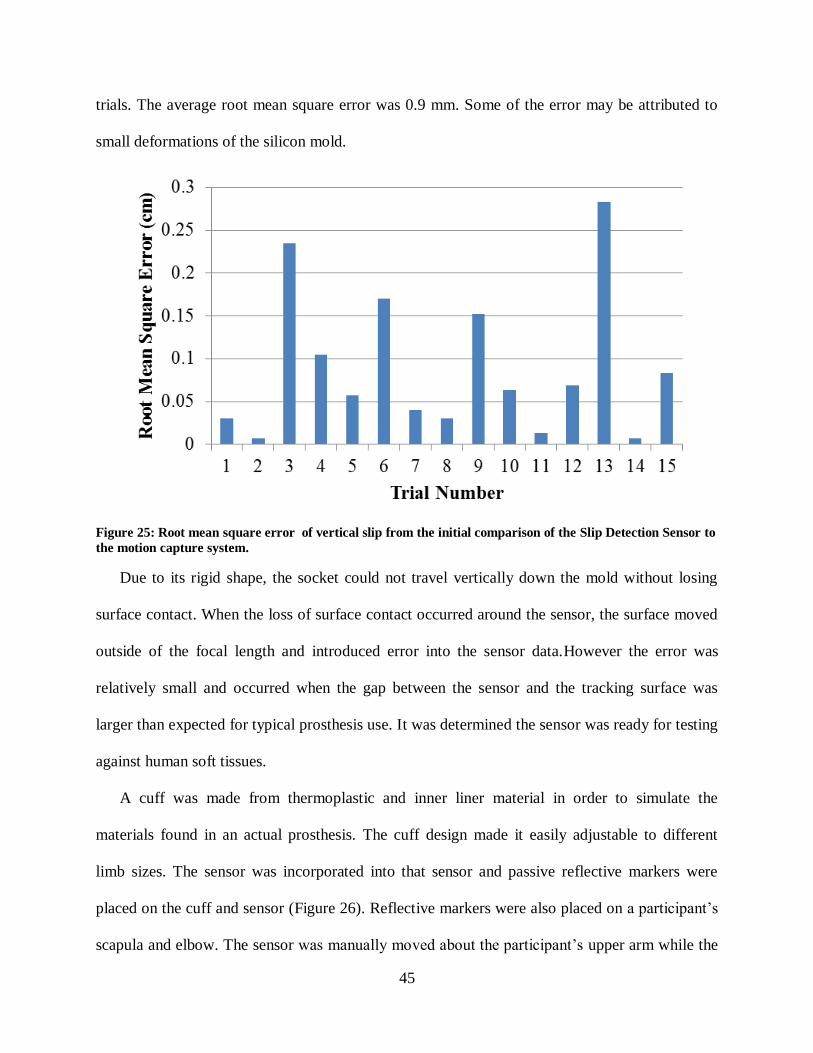
45
trials. The average root mean square error was 0.9 mm. Some of the error may be attributed to
small deformations of the silicon mold.
Figure 25: Root mean square error of vertical slip from the initial comparison of the Slip Detection Sensor to
the motion capture system.
Due to its rigid shape, the socket could not travel vertically down the mold without losing
surface contact. When the loss of surface contact occurred around the sensor, the surface moved
outside of the focal length and introduced error into the sensor data.However the error was
relatively small and occurred when the gap between the sensor and the tracking surface was
larger than expected for typical prosthesis use. It was determined the sensor was ready for testing
against human soft tissues.
A cuff was made from thermoplastic and inner liner material in order to simulate the
materials found in an actual prosthesis. The cuff design made it easily adjustable to different
limb sizes. The sensor was incorporated into that sensor and passive reflective markers were
placed on the cuff and sensor (Figure 26). Reflective markers were also placed on a participant’s
scapula and elbow. The sensor was manually moved about the participant’s upper arm while the
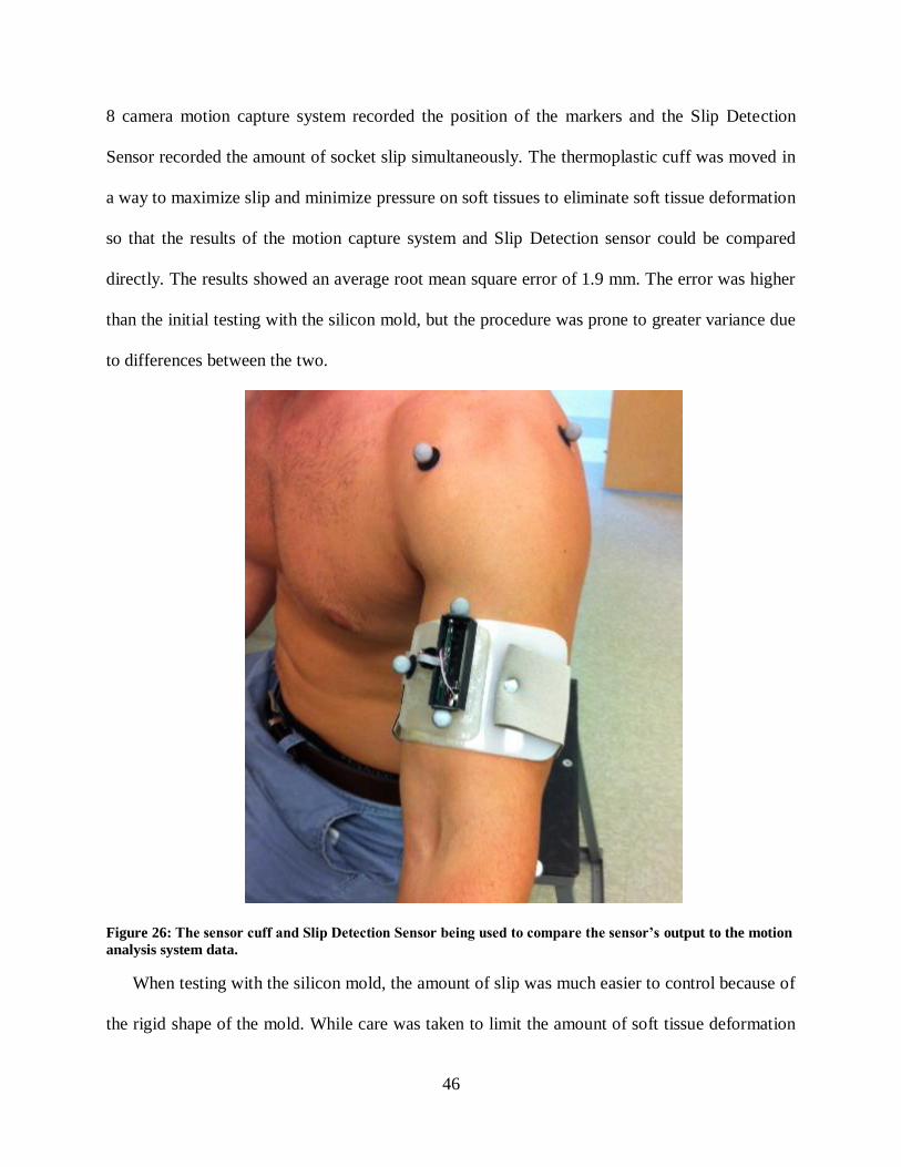
46
8 camera motion capture system recorded the position of the markers and the Slip Detection
Sensor recorded the amount of socket slip simultaneously. The thermoplastic cuff was moved in
a way to maximize slip and minimize pressure on soft tissues to eliminate soft tissue deformation
so that the results of the motion capture system and Slip Detection sensor could be compared
directly. The results showed an average root mean square error of 1.9 mm. The error was higher
than the initial testing with the silicon mold, but the procedure was prone to greater variance due
to differences between the two.
Figure 26: The sensor cuff and Slip Detection Sensor being used to compare the sensor’s output to the motion
analysis system data.
When testing with the silicon mold, the amount of slip was much easier to control because of
the rigid shape of the mold. While care was taken to limit the amount of soft tissue deformation

47
while moving the thermoplastic cuff, it was still possible for it to occur and interject error into
the data. Additionally, multiple participants increased the variation. Still, the observed error was
small and the true error was believed to be less with the removal of soft tissue deformation.
Therefore, confident in the performance of the sensor, it was determined it was ready for use in
transhumeral prosthetic sockets.
48
CHAPTER 4: STUDY PROCEDURES AND DATA ANALYSIS
All testing was completed at the Rehabilitation Robotics and Prosthetics Testbed (RRT) at
the University of South Florida. The collection procedures were approved by the Western
Institutional Review Board, who was contracted by the University of South Florida. Informed
consent was given by all participants before participation in the study. The goal of the cross-
sectional study was to measure the amount of movement occurring at the socket interface during
common tasks without interfering with the internal socket volume.
An eight camera Vicon motion capture system was used to collect data from six participants
performing RoM and activities of daily living (ADL) while using a transhumeral prosthesis. All
participants had a harness suspension system. Note, one participant had a pin-locking suspension
system, but regularly uses his prosthesis without the pin attached to the gel liner. The participant
completed the collection procedures with and without the pin attached to the gel liner. This
participant was counted as two participants (H04 and H05), bringing the total of participants to
seven. For the purposes of group statistics, only one data set from this individual was used to
avoid biasing the analysis to the results of the one individual. The data from H05, where the
participant used the pin-locking suspension system was excluded from the group statistics
because his other suspension system was more comparable to the other suspension systems in the
study. The characteristics of the participants and their prosthetic systems are shown in Table 3.
These participants all used a body-powered or hybrid (some components are body-powered
while other components are controlled by other means) prosthesis and used the same prosthetic

49
socket without a documented skin condition for a minimum of a two month period. The marker
set described in Chapter 2 was used to track the body segments during the tasks. The motion
analysis collection procedures were divided into two days. Figure 27 shows the flow of
participation in the study.
Table 3: Participants’ measurements and prosthesis/socket characteristics.
Figure 27: Flowchart of participation in the study.
4.1 First Collection Day Procedures
This day began with the prosthetist (PhD, Certified Prosthetist, Follow of the American
Academy of Orthotists and Prosthetists) taking several anthropomorphic measurements of the
participant. These measurements included residual limb circumference at the axilla and distal
ends, residual limb length, chest circumference, and lengths and circumferences of the arm and
forearm of the non-amputated side. Residual limb length was measured from both the axilla to
ID
Height
(cm)
Weight
(kg)
Prosthesis
Side
Acromion
to Distal
RL (cm)
Axilla to
Distal
RL (cm)
Suspension
System
Control
System
H01 180 81 Right 22 11 Harness BP
H02 174 80.7 Right 26 18 Suction Hybrid
H03 184 77 Left 42 27 Suction Hybrid
H04 183 102.5 Right 31 20 Harness BP
H05 183 102.5 Right 31 20 Pin-Locking BP
H06 172 109.3 Left 23 13 Suction Hybrid
H07 165 86 Right 35 22 Harness BP
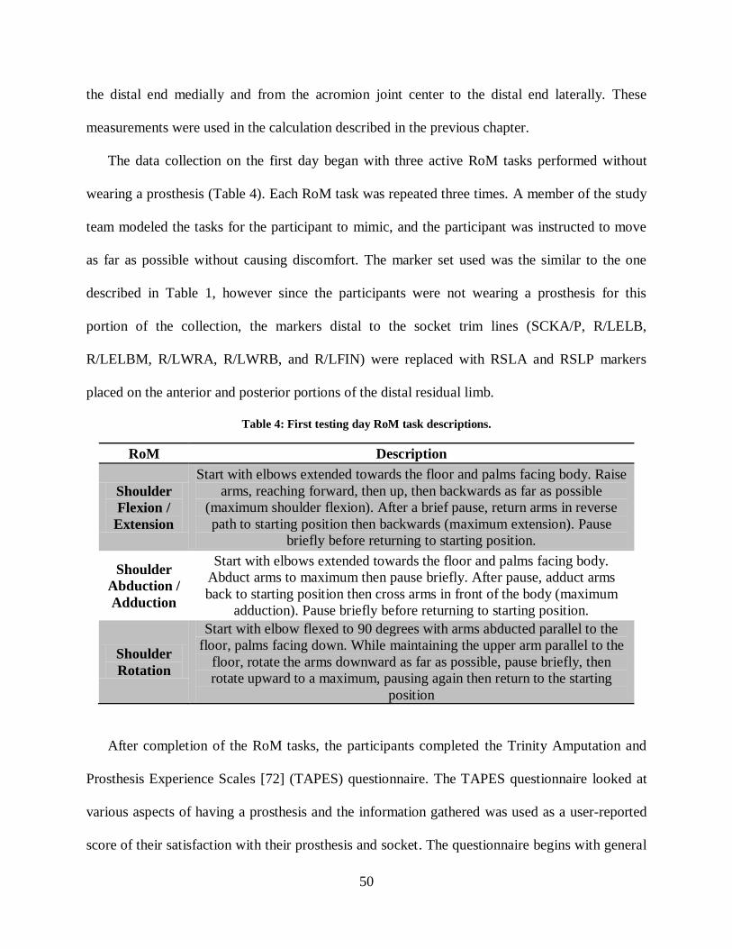
50
the distal end medially and from the acromion joint center to the distal end laterally. These
measurements were used in the calculation described in the previous chapter.
The data collection on the first day began with three active RoM tasks performed without
wearing a prosthesis (Table 4). Each RoM task was repeated three times. A member of the study
team modeled the tasks for the participant to mimic, and the participant was instructed to move
as far as possible without causing discomfort. The marker set used was the similar to the one
described in Table 1, however since the participants were not wearing a prosthesis for this
portion of the collection, the markers distal to the socket trim lines (SCKA/P, R/LELB,
R/LELBM, R/LWRA, R/LWRB, and R/LFIN) were replaced with RSLA and RSLP markers
placed on the anterior and posterior portions of the distal residual limb.
Table 4: First testing day RoM task descriptions.
RoM Description
Shoulder
Flexion /
Extension
Start with elbows extended towards the floor and palms facing body. Raise
arms, reaching forward, then up, then backwards as far as possible
(maximum shoulder flexion). After a brief pause, return arms in reverse
path to starting position then backwards (maximum extension). Pause
briefly before returning to starting position.
Shoulder
Abduction /
Adduction
Start with elbows extended towards the floor and palms facing body.
Abduct arms to maximum then pause briefly. After pause, adduct arms
back to starting position then cross arms in front of the body (maximum
adduction). Pause briefly before returning to starting position.
Shoulder
Rotation
Start with elbow flexed to 90 degrees with arms abducted parallel to the
floor, palms facing down. While maintaining the upper arm parallel to the
floor, rotate the arms downward as far as possible, pause briefly, then
rotate upward to a maximum, pausing again then return to the starting
position
After completion of the RoM tasks, the participants completed the Trinity Amputation and
Prosthesis Experience Scales [72] (TAPES) questionnaire. The TAPES questionnaire looked at
various aspects of having a prosthesis and the information gathered was used as a user-reported
score of their satisfaction with their prosthesis and socket. The questionnaire begins with general
51
questions such as age, amputation level, cause of amputation, and amount of experience with
prostheses. Part I asks participants to rate statements related to wearing a prosthesis, activities
performed during a typical day, and satisfaction with different aspects of their prosthesis. Part II
asks participants about amount of use of their device and health related questions such as
residual and phantom limb pain. This concluded the day one procedures for the participant.
While the participant completed the day one tasks above, the study prosthetist made a
positive mold of the original socket shape using alginate. The entire socket duplication process is
summarized in the Section 4.1.1. Once the prosthetist removed the alginate mold from the socket
and cleaned any residual material from the socket, the prosthesis was returned to the participant.
One week later, the participants returned to complete the second day procedures. During this
week gap, the prosthetist assembled the sensor embedded prosthesis using the socket equipped
with the optical sensor.
4.1.1 Socket Duplication
Duplication began by making a positive mold of the existing socket shape. The original
prosthesis was put in a bucket of sand to hold the prosthetic limb vertical, ensuring the alignment
was maintained (Figure 28). Once the vertical position was set, the inside of the original socket
was filled with alginate. A metal pipe was inserted vertically into the mixture and held up by
tongue depressors while the alginate sets. The metal pipe provides a connection to the vacuum
system used during a later step in the blister forming process as well as an indicator of the
vertical position of the positive mold. Some sockets have pre-flexion built in to help the amputee
operate the system, which was replicated with the sensor embedded prosthesis. Once the alginate
reached a solid state, it was removed from the original socket.

52
Figure 28: Process for making the positive mold representing the internal socket shape.
A negative mold of the alginate positive mold was made with plaster wraps, a more durable
material to maintain the mold shape. This negative mold was then filled with a plaster mixture
and allowed to solidify. This plaster mold was then smoothed of any impurities. For suction
sockets, additional steps were required. Before the thermoforming steps begin, the suction valve
was screwed into the side of the positive plaster mold. The positive mold was placed upside
down on a vacuum rig (Figure 29). Note this figure includes the suction valve port screwed into
the plaster mold. The clear thermoplastic socket was made using the blister forming technique. A
sheet of clear thermoplastic was placed in a metal pan with a hole removed in the center (Figure
30).
The metal pan and thermoplastic was placed in an oven (Figure 31) and heated at 325°F until
the plastic droops through the hole in the pan. The amount of droop desired is between two thirds
and three fourths of the desired socket depth.

53
Figure 29: Plaster mold with a suction valve is placed upside down on the vacuum rig.
Figure 30: Left: Sheet of thermoplastic; Right: Pan with hole to allow for droop of thermoplastic.
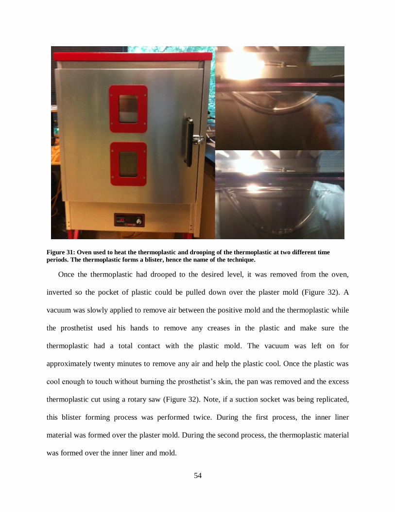
54
Figure 31: Oven used to heat the thermoplastic and drooping of the thermoplastic at two different time
periods. The thermoplastic forms a blister, hence the name of the technique.
Once the thermoplastic had drooped to the desired level, it was removed from the oven,
inverted so the pocket of plastic could be pulled down over the plaster mold (Figure 32). A
vacuum was slowly applied to remove air between the positive mold and the thermoplastic while
the prosthetist used his hands to remove any creases in the plastic and make sure the
thermoplastic had a total contact with the plastic mold. The vacuum was left on for
approximately twenty minutes to remove any air and help the plastic cool. Once the plastic was
cool enough to touch without burning the prosthetist’s skin, the pan was removed and the excess
thermoplastic cut using a rotary saw (Figure 32). Note, if a suction socket was being replicated,
this blister forming process was performed twice. During the first process, the inner liner
material was formed over the plaster mold. During the second process, the thermoplastic material
was formed over the inner liner and mold.

55
Figure 32: Forming the thermoplastic over the plaster mold, and removal of the excess material.
The socket was then clamped vertically using the metal pipe and the distal prosthetic
components were attached. The first step was to add hardening foam to the distal end. The two
part foam was mixed and poured into a masking tape ring constructed on the distal end of the
socket. Once the foam hardened, the tape was removed and the end of the foam was sanded
down so the trim line to elbow distance matched the measurements taken from the participant
during the first data collection day. The elbow component was secured to the sensor embedded
socket with epoxy and was then covered with a fiber glass wrap for additional support. Note a
generic set of body-powered components were used for all participants (Figure 33). This
included a right or left a right or left E400 45mm prefabricated elbow and forearm, a quick
disconnect wrist assembly, Hosmer hook 5XA, a quick disconnect insert assembly. A thermo
valve if a suction socket was being made.

56
Figure 33: A: E400 45 mm prefabricated elbow and forearm, B: Quick disconnect wrist assembly, C: Hosmer
hook 5XA, D: Quick Disconnect insert.
After the elbow was connected, the plaster mold and pipe was removed from the sensor
embedded socket. The trim lines of the socket were then smoothed with an electric sander until a
smooth finish was achieved. The wrist component was attached and secured with epoxy before
putting in the quick disconnect and Hosmer hook. Note, since the wrist component was difficult
to remove once secured with epoxy, a standard forearm length of 24 cm was used for all
participants. This length was ±1 cm from the appropriate length for all participants. Since the
amount of socket movement was being studied and not the function of the prosthesis, it was
assumed this difference in length would not significantly affect the results. The last step for the
socket duplication required the harness system to be attached to the arm. A Figure 8 harness was
used for all participants. Only one of the participants regularly used a chest strap harness system,
but was comfortable operating the Figure 8 harness system.
Once the prosthesis was complete, the slip detection sensor was added. A 3/4 inch drill bit
was used to cut out a hole in the wall of the socket, leaving stock allowance to ensure a snug fit.

57
The remaining material was removed with a Dremel tool until the sensor casing had a snug fit
and was flush with the interior wall of the socket. The hole was placed on the lateral most aspect
of the socket, roughly equal to the height of the axilla trim line.
4.2 Second Collection Day Procedures
The second day procedures required the participant to complete tasks with the original and
sensor embedded prostheses. The participants were asked to complete nine tasks, four RoM
(Table 5) and five ADL (Table 6), each one repeated three times. The ADL tasks were selected
to include a range of task weights and movements, allowing the results to be analyzed based off
the weight of the task and the movement of the residual limb during completion of the task. The
testing protocol was completed twice, once while wearing the original prosthesis and once
wearing the sensor embedded prosthesis. The marker set used for this day is described in Table
1. Participants were randomized into two groups that determined the prosthesis order.
Table 5: Second testing day RoM task descriptions.
RoM Description
Shoulder
Flexion /
Extension
Start with elbows extended towards the floor and palms facing body. Raise
arms, reaching forward, then up, then backwards as far as possible
(maximum shoulder flexion). After a brief pause, return arms in reverse
path to starting position then backwards (maximum extension). Pause
briefly before returning to starting position.
Shoulder
Abduction
/
Adduction
Start with elbows extended towards the floor and palms facing body.
Abduct arms to maximum then pause briefly. After pause, adduct arms back
to starting position then cross arms in front of the body (maximum
adduction). Pause briefly before returning to starting position.
Shoulder
Rotation
Start with elbow flexed to 90 degrees with arms abducted parallel to the
floor, palms facing down. While maintaining the upper arm parallel to the
floor, rotate the arms downward as far as possible, pause briefly, then rotate
upward to a maximum, pausing again then return to the starting position
Elbow
Flexion /
Extension
Start with elbows extended towards the floor and palms facing body. Flex
elbows until maximum is reached, pause briefly, then extend elbows until
back to the terminal position.

58
Table 6: Functional task descriptions.
ADL Description
Unilateral
Lift
Participant picks up and places a series of weights form one spot on a 3 feet
high shelf to another spot 3 feet away on the same shelf. The participant must
hold the object above the shelf (cannot drag the object) during the transfer.
The task weights were 5, 10, and 15 lbs.
Bilateral
Lift
Participant lifts a basket containing a series of weights from the floor to a 3
feet high shelf, and then back to the original position. The task weights were
10, 25, and 50 lbs.
Walk and
Carry
Participant walks on a treadmill for 1 minute while carrying a gallon carton of
milk (task weight approximately 8 lb) with the prosthesis.
Fold a
Towel
Participant stands in front of a table with a bath towel on top. Participant folds
the towel in half lengthwise, then in half widthwise, then in half lengthwise.
Modified
Box and
Blocks
16 blocks are placed in 4 rows of 4 on one side of a box with a partition in the
middle. The objective is to move one block at a time to the same spot on the
other side. Participants were instructed to start at the lower inside corner and
complete that row before moving to the next. Participant had 1 minute to move
as many blocks as they can. The box started so the blocks start on the same
side as the participant's prosthesis.
Changes in the residual limb volume can affect the fit of the socket and can occur during the
collection procedures. Therefore it is important to measure the volume of the residual limb.
Volume measurement was completed before and after testing both prostheses. To do so
Archimedes principle was applied, which states that the force exerted on an immersed body is
equal to the weight of the fluid displaced by that body. Participants stood next to a table with a
bucket of water placed on top of a digital scale. The digital scale was zeroed with the bucket of
water on top. This line was drawn at the area of the limb that the proximal trim lines of the
socket rests, which marks the end of the socket. Participants lowered their residual limb into the
water until the water level reached a line drawn on the residual limb. The scale measured the
change in weight, or buoyancy force exerted on the residual limb, which is equal to the weight of
the water displaced. The volume of the body submerged was calculated dividing by density

59
(Equation 8). The mass of water is given by the scale and the density of water is known, leaving
volume as the only unknown variable.
(8)
4.3 Data Analysis
The goal of the dissertation was to quantify socket interface movements using motion
analysis and the Slip Detection Sensor and test the hypotheses defined in the introduction. The
information gathered was used to determine the range of socket movement that occurred during a
series of ADL tasks. Two types of analysis were performed. The data from the RoM tasks were
analyzed using a repeated measures analysis of variance (repeated measures ANOVA). The data
from the ADL tasks was analyzed using a multivariate linear regression to analyze the effects of
four cofactors on the amount of socket movement. These cofactors were identified as residual
limb RoM during task completion, the weight of each task, residual limb length, and elbow
angle. The second analysis performed used analytical results on an individual participant basis.
4.3.1 TAPES Questionnaire Analysis
The results of the TAPES questionnaire were used to provide a level of satisfaction with the
prosthetic system indicated by the participant. The participants were instructed to complete the
questionnaire in regards to their original prosthesis. The scoring for the TAPES was analyzed for
each individual section. Note, some of the participants had amputations to various limbs. The
sections scores indicated their level of adjustment to using a prosthesis, the degree to which a
prosthesis limited their ability to perform activities, and satisfactions with various aspects of the
prosthesis respectively. The individual responses for each section were scored based off of scale
ratings. Responses with a higher score indicated a greater level of adjustment to prosthetic use,
increased limitation to perform activities, and a greater satisfaction level with various aspects of
60
the prosthesis respectively for each section. The participant’s responses within a section were
summed and divided by the highest total possible score for that section. The TAPES
questionnaire also had the participants rate their overall satisfaction with their prosthesis on a
scale of 1-10, with 10 being the highest possible satisfaction. The average hours (total, not
continuous usage) of prosthesis use per day was also collected. The TAPES results for all of the
participants are reported in Table 7 in the results section.
4.3.2 RoM Tasks Analysis
The RoM of the contralateral limb, residual limb without wearing a prosthesis, residual limb
while wearing the original prosthesis, and residual limb while wearing the sensor embedded
prosthesis were compared to show the effect the amputation and various prostheses had on the
RoM for each participant. Euler angles between the scapula and upper arm/residual limb
segments were calculated based off the motion capture data using the model described in Chapter
2. The average of the maximum and minimum values over the RoM trials for the amount of
flexion, abduction, and rotation for the contralateral and residual limb (for all three conditions)
were found. The standard deviation was also calculated using the maximum and minimum values
for each degree of freedom respectively. A one-tailed repeated measures ANOVA was used to
analyze significant differences between the four factors, using α=0.05.
4.3.3 ADL Tasks Analysis
The amount of socket interface rotation for both the original and sensor embedded prostheses
was calculated from the motion capture data for all trials following the procedures described in
Chapter 2. Euler angles between the residual limb and socket segments were calculated. The
amount of socket anterior-posterior and medial-lateral tilt were reported for each of the trials by
finding the maximum and minimum values of each direction of movement. The standard
61
deviation was calculated the same way as the RoM data, using the maximum and minimum
values. Equivalent angle-axis rotations between the scapula and residual limb were used to
represent residual limb movement. This was done to give one angle representing residual limb
movement, because the specific direction of movement was not needed for the residual limb (i.e.
Euler angle that tell the amount of flexion, abduction, and rotation).
The amount of vertical translation of the socket due to soft tissue deformation was calculated
using the motion capture data for each trial. The average amount of translation along the long
axis of the residual limb was found by calculating the distance between the origins of the residual
limb and socket segments. The averages of the maximum and minimum values were used to
provide the full RoM of vertical translation. The standard deviation was found for the maximum
and minimum values for each task. The amount of vertical and rotational slip was found by
taking the difference of the maximum and minimum values of the Slip Detection Sensor data for
each direction of movement. These values were averaged for each individual task and the
standard deviation was found. The rotational slip was calculated in millimeters (mm) of
movement. Therefore, the values do not represent a rotational angle of slip, rather a distance
representing the arc length.
Linear regression is used to show the dependence between two variables. The Pearson
correlation coefficient is the most common type of correlation which shows the linear
relationship between two variables. The various types of socket movement were correlated to
two data sets; the range of residual limb movement during the task completion and the weight of
each task, referred to as task weight. A linear regression was fit to each of the correlation graphs
to find the R2 value, or coefficient of determination. Taking the square root of the coefficient of
determination solves for the Pearson’s correlation coefficient (Pearson’s r). The Pearson’s r
62
value was compared to critical values found in statistics tables for one tailed test assuming an
α=0.05. Data from the participants able to complete the entire study protocol was used in a
multivariate linear regression to analyze the effect of cofactors on the amount of socket
movement. The cofactors were identified as residual limb movement during the task, the weight
of each task, elbow angle and residual limb length.

63
CHAPTER 5: RESULTS
5.1 TAPES Questionnaire
The results of the TAPES questionnaire are summarized in Table 7 for all of the participants.
None of the participants scored socket interface comfort as a three out of three. Two of the
participants, H06 and H07, scored the socket interface comfort as a one out of three. The same
two participants were the only ones to rate their overall satisfaction with their prosthesis less than
8, instead gave much lower scores of three and one respectively. These two participants also
recorded the lowest usage.
Table 7: Results of the TAPES questionnaire for all of the participants.
5.2 Shoulder RoM
The shoulder RoM for the non-amputated limb, the residual limb without wearing a
prosthesis, the residual limb while wearing the participant’s original prosthesis, and the residual
limb while wearing the sensor embedded prosthesis are shown below. Figure 34 shows the
ID
Level of
Adjustment
Activity
Limitation
Satisfaction
with Various
Aspects
Satisfaction
with Socket
Comfort
Overall
Satisfaction
1-10
Usage
(hr/day)
H01 70% 75% 67% 2/3 8 10
H02 83% 50% 96% 2/3 8 7
H03 87% 63% 79% 2/3 8 15
H04 92% 25% 79% 2/3 8 5
H06 89% 43% 46% 1/3 3 1.5
H07 40% 100% 38% 1/3 1 1

64
amount of shoulder flexion, Figure 35 shows the amount of shoulder abduction, and Figure 36
shows the amount of shoulder rotation.
Figure 34: Shoulder flexion results from the RoM tasks for the study sample.
Figure 35: Shoulder abduction results from the RoM tasks for the study sample.
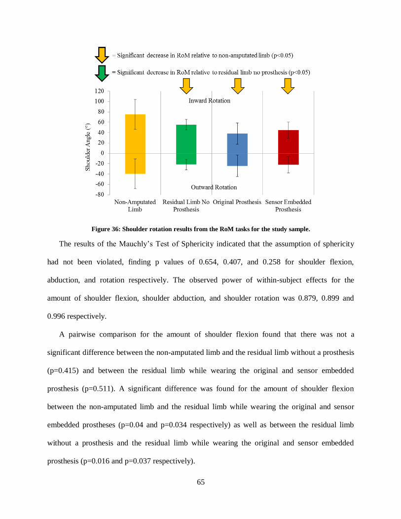
65
Figure 36: Shoulder rotation results from the RoM tasks for the study sample.
The results of the Mauchly’s Test of Sphericity indicated that the assumption of sphericity
had not been violated, finding p values of 0.654, 0.407, and 0.258 for shoulder flexion,
abduction, and rotation respectively. The observed power of within-subject effects for the
amount of shoulder flexion, shoulder abduction, and shoulder rotation was 0.879, 0.899 and
0.996 respectively.
A pairwise comparison for the amount of shoulder flexion found that there was not a
significant difference between the non-amputated limb and the residual limb without a prosthesis
(p=0.415) and between the residual limb while wearing the original and sensor embedded
prosthesis (p=0.511). A significant difference was found for the amount of shoulder flexion
between the non-amputated limb and the residual limb while wearing the original and sensor
embedded prostheses (p=0.04 and p=0.034 respectively) as well as between the residual limb
without a prosthesis and the residual limb while wearing the original and sensor embedded
prosthesis (p=0.016 and p=0.037 respectively).

66
A pairwise comparison for the amount of shoulder abduction found that there was not a
significant difference between the non-amputated limb and the residual limb without a prosthesis
(p=0.217) and between the residual limb while wearing the original and sensor embedded
prosthesis (p=0.922). A significant difference was found for the amount of shoulder abduction
between the non-amputated limb and the residual limb while wearing the original prosthesis
(p=0.031) as well as between the residual limb without a prosthesis and the residual limb while
wearing the original and sensor embedded prosthesis (p=0.015 and p=0.030 respectively). The
amount of shoulder abduction between the non-amputated limb and the residual limb while
wearing the sensor embedded prosthesis was very close to being significant (p=0.057).
A pairwise comparison for the amount of shoulder rotation found that there was a significant
difference between the non-amputated limb and the residual limb without a prosthesis (p=0.027)
and the residual limb while wearing the original and sensor embedded prosthesis (p=0.008 and
p=0.006 respectively). The residual limb without a prosthesis had a significant decrease in
shoulder rotation compared to the non-amputated limb, but it may be due to errors in the motion
capture precision in this plane of movement. This effect is discussed further in the Chapter 7. A
significant difference was not found for the amount of shoulder rotation between the non-
amputated limb and the residual limb while wearing the original and sensor embedded prostheses
(p=0.107 and p=0.338 respectively) as well as between the residual limb while wearing the
original and sensor embedded prosthesis (p=0.377).
5.3 Socket Movement During the ADL Tasks
The various types of socket movement were analyzed for each of the ADL tasks. The average
anterior-posterior socket tilt and average medial-lateral socket tilt for each of the tasks are shown
in Figure 37 and Figure 38 respectively.
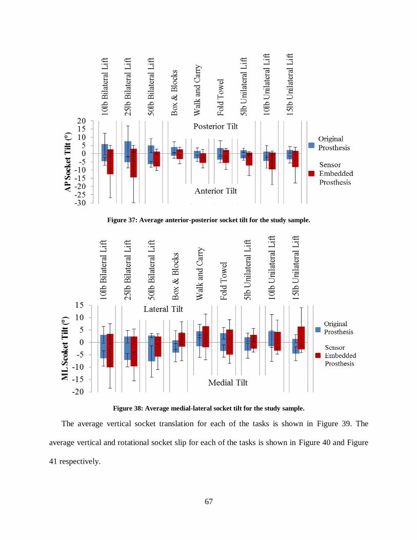
67
Figure 37: Average anterior-posterior socket tilt for the study sample.
Figure 38: Average medial-lateral socket tilt for the study sample.
The average vertical socket translation for each of the tasks is shown in Figure 39. The
average vertical and rotational socket slip for each of the tasks is shown in Figure 40 and Figure
41 respectively.

68
Figure 39: Average vertical socket translation for the study sample.
Figure 40: Average vertical socket slip for the study sample.
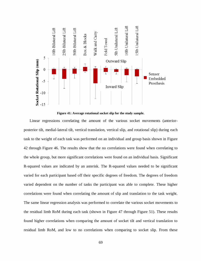
69
Figure 41: Average rotational socket slip for the study sample.
Linear regressions correlating the amount of the various socket movements (anterior-
posterior tilt, medial-lateral tilt, vertical translation, vertical slip, and rotational slip) during each
task to the weight of each task was performed on an individual and group basis shown in Figure
42 through Figure 46. The results show that the no correlations were found when correlating to
the whole group, but more significant correlations were found on an individual basis. Significant
R-squared values are indicated by an asterisk. The R-squared values needed to be significant
varied for each participant based off their specific degrees of freedom. The degrees of freedom
varied dependent on the number of tasks the participant was able to complete. These higher
correlations were found when correlating the amount of slip and translation to the task weight.
The same linear regression analysis was performed to correlate the various socket movements to
the residual limb RoM during each task (shown in Figure 47 through Figure 51). These results
found higher correlations when comparing the amount of socket tilt and vertical translation to
residual limb RoM, and low to no correlations when comparing to socket slip. From these

70
results, it was determined an individual analysis of socket movement should be performed for
each of the participants. These results are further discussed in the next chapter.
Figure 42: Linear regression plot correlating anterior-posterior socket tilt to task weight.
Figure 43: Linear regression plot correlating medial-lateral socket tilt to task weight.
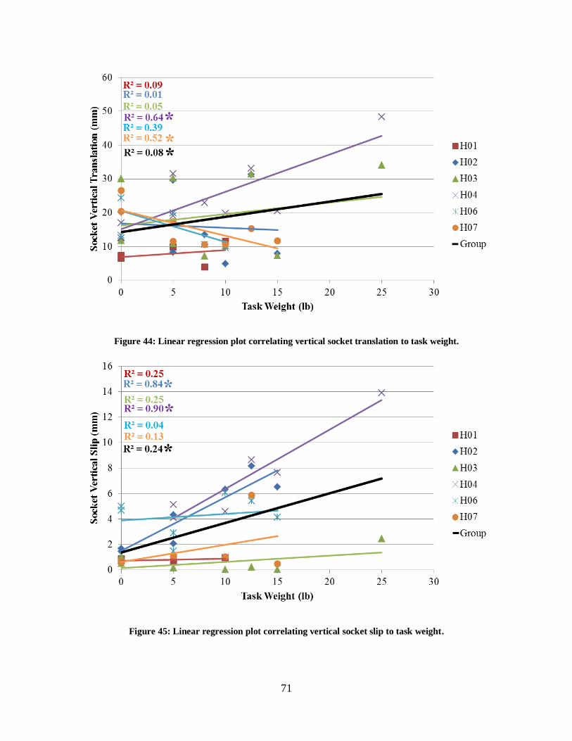
71
Figure 44: Linear regression plot correlating vertical socket translation to task weight.
Figure 45: Linear regression plot correlating vertical socket slip to task weight.

72
Figure 46: Linear regression plot correlating rotational socket slip to task weight.
Figure 47: Linear regression plot correlating anterior-posterior socket tilt to residual limb RoM during the
task.

73
Figure 48: Linear regression plot correlating anterior-posterior socket tilt to residual limb RoM during the
task.
Figure 49: Linear regression plot correlating vertical socket translation to residual limb RoM during the task.
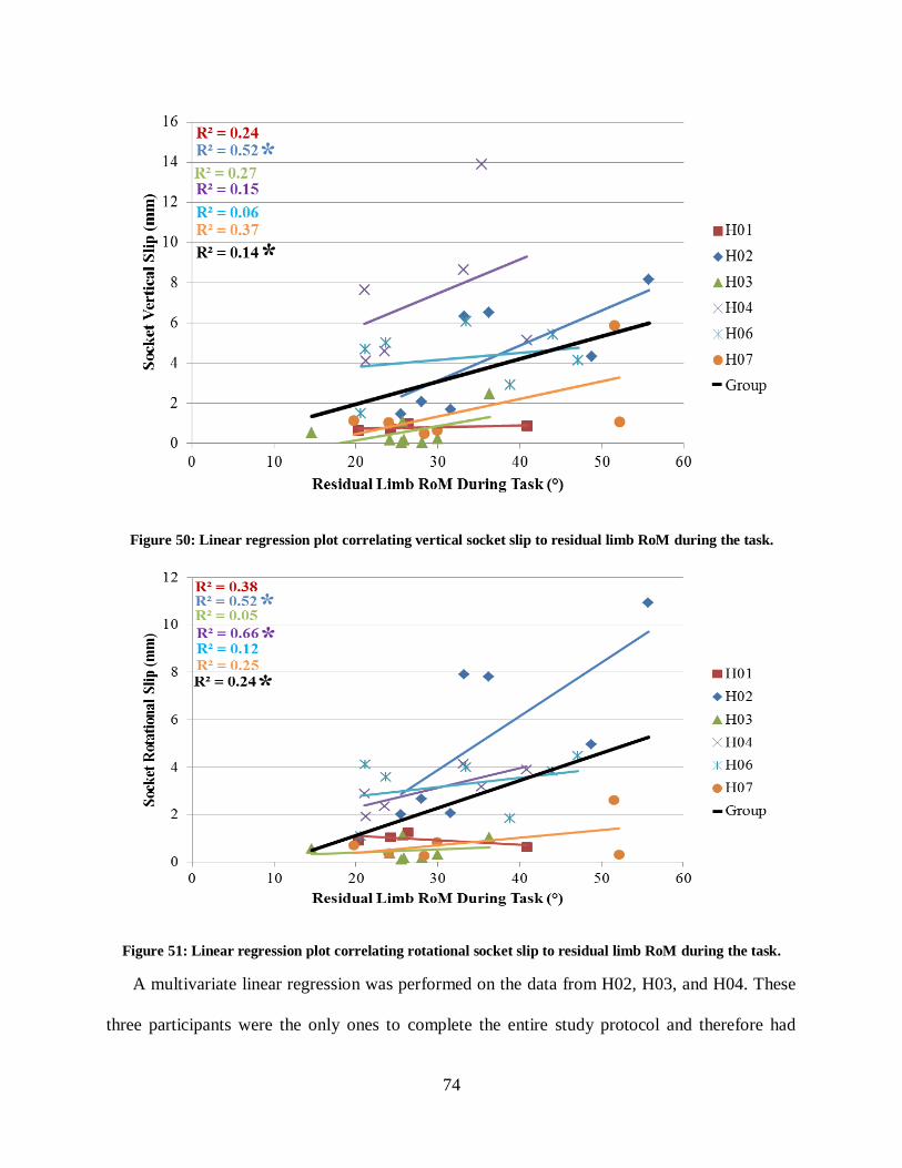
74
Figure 50: Linear regression plot correlating vertical socket slip to residual limb RoM during the task.
Figure 51: Linear regression plot correlating rotational socket slip to residual limb RoM during the task.
A multivariate linear regression was performed on the data from H02, H03, and H04. These
three participants were the only ones to complete the entire study protocol and therefore had
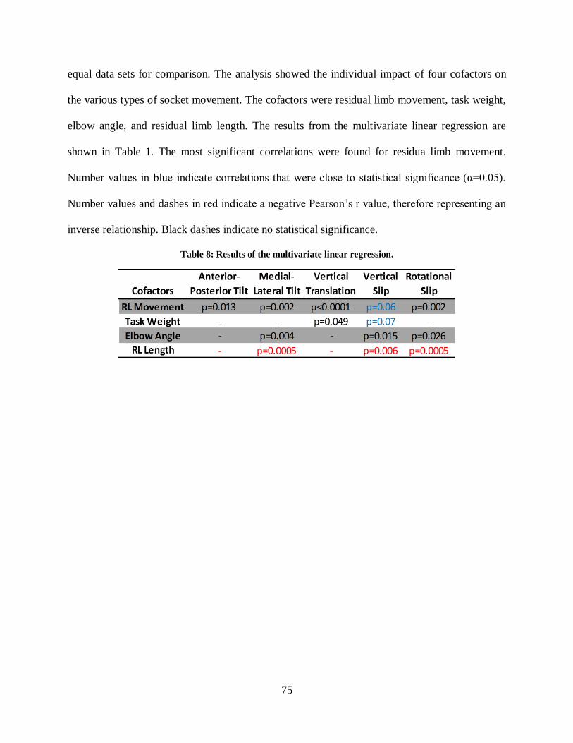
75
equal data sets for comparison. The analysis showed the individual impact of four cofactors on
the various types of socket movement. The cofactors were residual limb movement, task weight,
elbow angle, and residual limb length. The results from the multivariate linear regression are
shown in Table 1. The most significant correlations were found for residua limb movement.
Number values in blue indicate correlations that were close to statistical significance (α=0.05).
Number values and dashes in red indicate a negative Pearson’s r value, therefore representing an
inverse relationship. Black dashes indicate no statistical significance.
Table 8: Results of the multivariate linear regression.

76
CHAPTER 6: RESULTS ANALYSIS AND SOCKET DESIGN
The methods presented in this dissertation are useful for the measurement of socket interface
movement and may have an impact on the socket prescription and fitting procedures. The results
of the previous chapter showed the maximum and minimum values of the various types of socket
movement and how it changed with each task. Additionally, linear regressions were shown for
each participant as well as the whole group comparing different socket movements to various
outcomes.
This chapter will evaluate the results of each participant, showing his individual data and
make recommendations for how a prosthetist could potentially use this data to analyze socket
performance. Not all of the figures and linear regressions presented in the previous chapter will
be used to analyze an individual participant. Review of the figures in Chapter 5 show that the
amount of socket tilt (both anterior-posterior and medial-lateral) and vertical translation were
correlated more with residual limb movement and the amount of vertical and rotational slip were
correlated more with task weight. Therefore, only those figures will be used in the analysis
presented in this chapter. Limiting the data to only the most useful correlations will keep the
prosthetist from being bombarded with data that does not provide useful insight to the
interactions occurring at the socket interface and help them focus on the data that does provide
useful information. This section will also be useful for explaining the differences found between
the original and sensor embedded prostheses in terms of the amount of movement found. Similar
to the previous chapter, significant R-squared values are indicated by an asterisk.

77
6.1 H01
This participant had the shortest residual limb of the study cohort. He reported wearing his
prosthesis for many hours a day; however he wore it primarily for aesthetic purposes rather than
function. He described the socket as loose fitting, which probably made the socket more
comfortable but less functional. The RoM data for H01 showed that by wearing his original
prosthesis, he had a 22%, 24%, and 31% reduction in residual limb shoulder flexion, abduction,
and rotation respectively. This considerable reduction in RoM does not take into account
movement at the socket interface, and reports the difference in residual limb movement. This
reduction in RoM may stem from the prosthetic socket not being able to transfer the motions of
the residual limb to the prosthesis due to the short lever of the residual limb, as well as the
weight of the prosthesis being too much for the residual limb musculature to lift to its full
potential.
Figure 52 shows the correlation between anterior-posterior tilt of the socket and the amount
of residual limb movement. The Pearson Correlation Coefficient was found to be significant
(p=0.027) for the sensor embedded prosthesis, but not for the original prosthesis. The same
correlation plots were made for the amount of medial-lateral tilt of the socket, but no significant
correlations were found. Figure 53 shows the correlation to residual limb movement and task
weight respectively. The amount of socket vertical translation had significant correlations for
both the original and sensor embedded prostheses with the amount of residual limb movement
(p=0.023 and 0.027 respectively). These results are shown in Figure 54. The amount of socket
slip was assessed for the sensor embedded prosthesis only. There were no significant correlations
between the vertical and rotational slip RoM and the task weight. These correlations plots are
shown in Figure 55.

78
Figure 52: Linear regression for H01 correlating anterior-posterior socket tilt RoM and residual limb RoM
for both prostheses.
Figure 53: Linear regression for H01 correlating medial-lateral socket tilt RoM and residual limb RoM for
both prostheses.
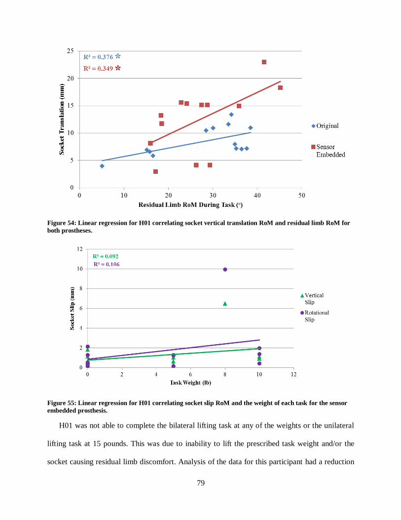
79
Figure 54: Linear regression for H01 correlating socket vertical translation RoM and residual limb RoM for
both prostheses.
Figure 55: Linear regression for H01 correlating socket slip RoM and the weight of each task for the sensor
embedded prosthesis.
H01 was not able to complete the bilateral lifting task at any of the weights or the unilateral
lifting task at 15 pounds. This was due to inability to lift the prescribed task weight and/or the
socket causing residual limb discomfort. Analysis of the data for this participant had a reduction
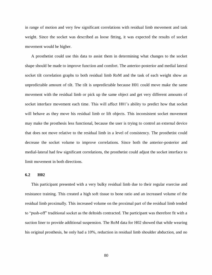
80
in range of motion and very few significant correlations with residual limb movement and task
weight. Since the socket was described as loose fitting, it was expected the results of socket
movement would be higher.
A prosthetist could use this data to assist them in determining what changes to the socket
shape should be made to improve function and comfort. The anterior-posterior and medial lateral
socket tilt correlation graphs to both residual limb RoM and the task of each weight show an
unpredictable amount of tilt. The tilt is unpredictable because H01 could move make the same
movement with the residual limb or pick up the same object and get very different amounts of
socket interface movement each time. This will affect H01’s ability to predict how that socket
will behave as they move his residual limb or lift objects. This inconsistent socket movement
may make the prosthesis less functional, because the user is trying to control an external device
that does not move relative to the residual limb in a level of consistency. The prosthetist could
decrease the socket volume to improve correlations. Since both the anterior-posterior and
medial-lateral had few significant correlations, the prosthetist could adjust the socket interface to
limit movement in both directions.
6.2 H02
This participant presented with a very bulky residual limb due to their regular exercise and
resistance training. This created a high soft tissue to bone ratio and an increased volume of the
residual limb proximally. This increased volume on the proximal part of the residual limb tended
to “push-off” traditional socket as the deltoids contracted. The participant was therefore fit with a
suction liner to provide additional suspension. The RoM data for H02 showed that while wearing
his original prosthesis, he only had a 10%, reduction in residual limb shoulder abduction, and no

81
reduction in RoM for shoulder flexion and rotation. These data suggest that the socket shape is
effective at capturing the residual limb movements and transferring them to the prosthesis.
Figure 56 shows the correlation between anterior-posterior tilt of the socket and the amount
of residual limb movement. The Pearson Correlation Coefficient was found to be significant for
both the original and sensor embedded prosthesis (p<0.0001 for both prostheses). The same
correlation plot was made for the amount of medial-lateral tilt of the socket, and significant
correlations were found when correlating to residual limb RoM (p<0.0001 for both prostheses).
Figure 57 shows the correlation to residual limb movement. The amount of socket vertical
translation had significant correlations for both the original and sensor embedded prostheses with
the amount of residual limb movement (p<0.0001 and p=0.001 respectively). These results are
shown in Figure 58. Again, the amount of socket slip was assessed for the sensor embedded
prosthesis only. There were significant correlations between the vertical and rotational slip RoM
and task weight (p<0.0001 for both prostheses). The correlation plot is shown in Figure 59.
Figure 56: Linear regression for H02 correlating anterior-posterior socket tilt RoM and residual limb RoM
for both prostheses.
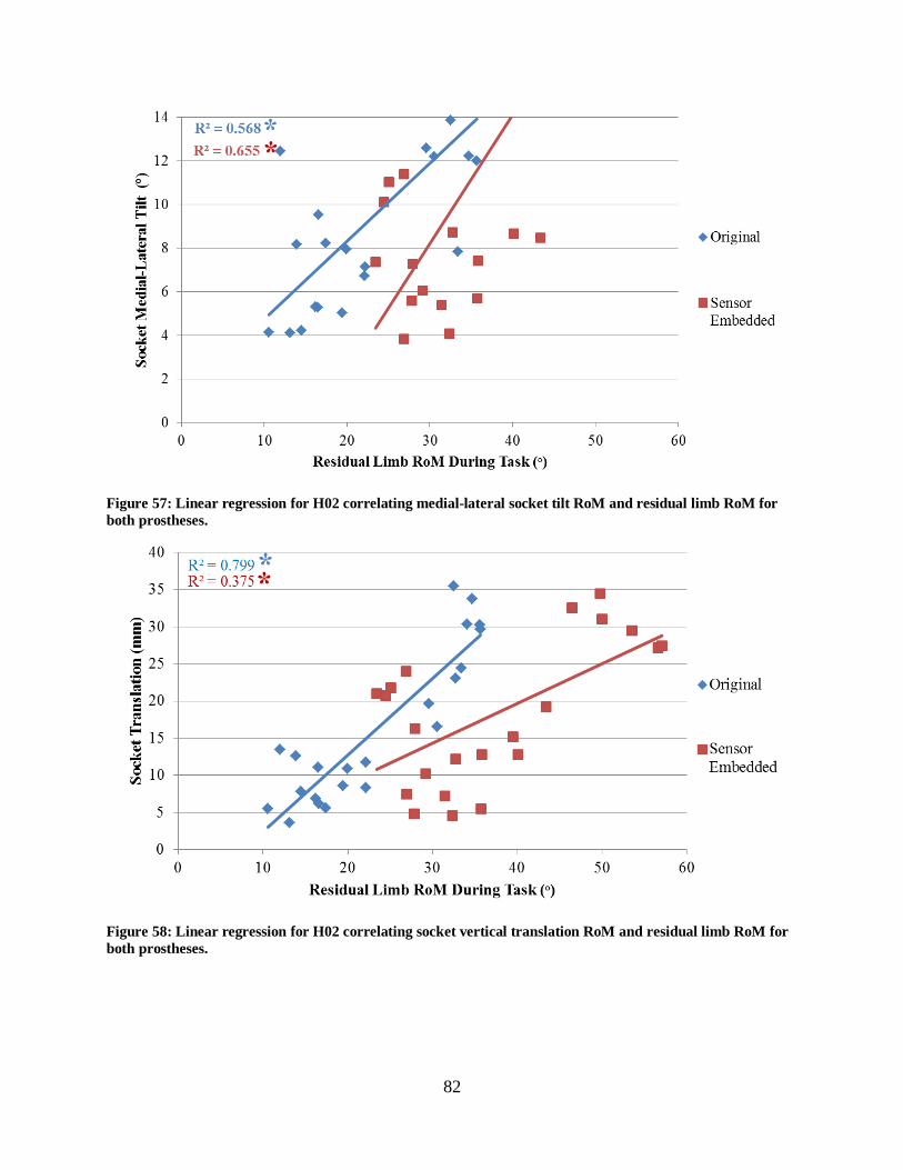
82
Figure 57: Linear regression for H02 correlating medial-lateral socket tilt RoM and residual limb RoM for
both prostheses.
Figure 58: Linear regression for H02 correlating socket vertical translation RoM and residual limb RoM for
both prostheses.

83
Figure 59: Linear regression for H02 correlating socket slip RoM and the weight of each task for the sensor
embedded prostheses.
Unlike H01, H02 was able to complete all of the tasks in the protocol except for the 50 lb
bilateral lift, which was due to a previous back injury and not to the prosthesis. The linear
regression results show high correlations in many of the comparisons, but the highest being
between socket tilt in both the anterior-posterior and medial-lateral directions to residual limb
RoM as well as vertical and rotational slip to task weight. The amount of tilt was not dependent
on the task weight, but was dependent on residual limb movement. Socket slip seemed to be
impacted by task weight as shown in Figure 59.
The sensor embedded prosthesis had a higher magnitude of socket rotation and translation for
all of the trials. A suction valve was included but not an inner flexible liner, which may have
changed the frictional properties with the suction liner worn over the residual limb. This resulted
in a reduced amount of suction and therefore allowed more socket movement. However the

84
sensor embedded prosthesis still had significant correlations among the same categories, but with
an increased magnitude of movement.
The case study provides an excellent example of how a prosthetist could use socket
movement data to evaluate and redesign a socket shape. Considering only the original prosthesis
(blue dots and trend line) for this example, the prosthetist can see the amount of movement
compared to various measures. Analysis of the anterior-posterior socket tilt versus residual limb
RoM shows a strong correlation between the two, where the more H02 moves their residual
limb, the more movement at the interface they experience (Figure 56). The same result is found
for the amount of medial-lateral tilt (Figure 57). One thing a prosthetist could notice from these
two figures is that while the Pearson’s r is significant, the magnitude of socket tilt in either
direction is also high. The prosthetist could redesign the shape to increase the pre-compression of
the soft tissues and eliminate some of the tilting movement. The prosthetist would retest the new
design with the hopes that the data points translate closer to the horizontal axis and the slope of
the linear regression trend line is reduced. For the case of H02, a patient with muscular
development on the shoulder and residual limb, it may be difficult to lower the amount of socket
tilt due to the increased soft tissue to bone ratio. Another course the prosthetist could analyze
would be to quantitatively compare different socket suspensions and see what method would
keep the prosthesis suspended on the residual limb the best. H02 may be a better candidate for a
pin-locking suspension over suction suspension, and this method of measurement would be a
great indicator of that.
H02 also had a significant correlation between the amount of socket translation and residual
limb RoM. The amount of socket vertical and rotational slip had a high correlation with both
residual limb RoM and task weight, but had a more significant correlation with task weight. The

85
data found upwards of 30 mm of translation for H02, with the amount of vertical slip less than 10
mm. Rotational slip reached slightly higher levels, topping out at 13 mm. The prosthetist could
try to reduce the socket volume to create a tighter fit and reduce the magnitudes of these
movements, but that may difficult due to the extra soft tissues. The magnitudes of movement
were some of the highest in the study sample, but the correlations were also among the highest in
the group.
6.3 H03
This participant had the longest residual limb of the study sample and had an elbow
disarticulation. Since his prosthesis still included an elbow unit, he was allowed to participate in
the study. He reported wearing his prosthesis for many hours a day and being a very proficient
prosthesis user. The RoM data for H03 showed that while wearing his original prosthesis, he had
a 27%, 37%, and 5% reduction in residual limb shoulder flexion, abduction, and rotation
respectively. It is interesting to note for H03, the sensor embedded prosthesis ended up being a
much tighter fit than their original prosthesis. By donning the sensor embedded prosthesis, H03
had a 4%, 14%, and 0% reduction in residual limb shoulder flexion, abduction, and rotation
respectively.
Figure 60 shows the correlation between anterior-posterior tilt of the socket and the amount
of residual limb movement. The Pearson Correlation Coefficient was found to be significant for
both the original and sensor embedded prosthesis (p<0.0001 and p=0.0005 respectively). The
same correlation plots were made for the amount of medial-lateral tilt of the socket, and
significant correlations were found for the original prosthesis when correlating to residual limb
RoM (p<0.0001) but not for the sensor embedded prosthesis. Figure 61 shows the correlation to
residual limb movement and task weight respectively. The amount of socket vertical translation
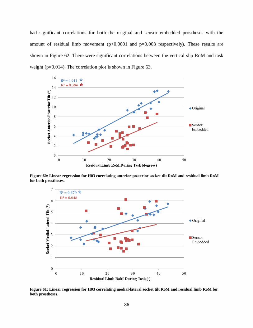
86
had significant correlations for both the original and sensor embedded prostheses with the
amount of residual limb movement (p<0.0001 and p=0.003 respectively). These results are
shown in Figure 62. There were significant correlations between the vertical slip RoM and task
weight (p=0.014). The correlation plot is shown in Figure 63.
Figure 60: Linear regression for H03 correlating anterior-posterior socket tilt RoM and residual limb RoM
for both prostheses.
Figure 61: Linear regression for H03 correlating medial-lateral socket tilt RoM and residual limb RoM for
both prostheses.

87
Figure 62: Linear regression for H03 correlating vertical socket translation RoM and residual limb RoM for
both prostheses.
Figure 63: Linear regression for H03 correlating socket slip RoM and weight of each task for the sensor
embedded prostheses.
H03 was able to complete the all of the tasks prescribed in the study protocol. The correlation
plots show a significant correlation with the original prosthesis in terms of rotation and
translation of the socket. Evaluation of the results shows high correlations across the many of the

88
same correlations that were found with H02. Again the strongest correlations were for anterior-
posterior/medial-lateral socket tilt and residual limb RoM, and vertical socket translation and
residual limb RoM. The vertical and rotational slip data did not have as strong of a correlation as
it did with H02 but may be due to the increase tightness of the sensor embedded prosthesis. The
sensor embedded prosthesis was a noticeably tighter fit than the original prosthesis, to the point
where H03 was almost unable to get his residual limb into the socket. This resulted in less
movement at the interface, which can be seen by the concentration of red points at the lower
portion of the correlation plots. Also the amount of slip was very minimal, most likely related to
the tight fit. These results are interesting in that it shows that creating a tighter interface lowers
the amount of socket tilt and translation. It could be assumed that socket slip was reduced also
but that claim was not tested because the sensor was only embedded into the duplicate prosthesis.
A prosthetist could look at the difference between the anterior-posterior/medial-lateral socket
tilts and residual limb RoM and see that the socket had less movement in the medial-lateral
direction. The prosthetist could decide they want to make the socket tilt the same in both
directions and adjust the socket shape to limit more anterior-posterior tilt. While the sensor
embedded prosthesis lowered movement at the socket interface, it worsened the correlation
coefficients across all outcomes, and may potentially be a worse fit than the original prosthesis,
even though it reduces movement. The sensor embedded socket may be too tight to be worn for a
long time, something that cannot be tested in a relatively short laboratory session. The prosthetist
could use his experience as well as the quantified socket interface movement to determine the
appropriate socket shape by balancing the amount of movement and strength of the correlation
coefficients. The correlations of the different socket tilts and translation to residual limb
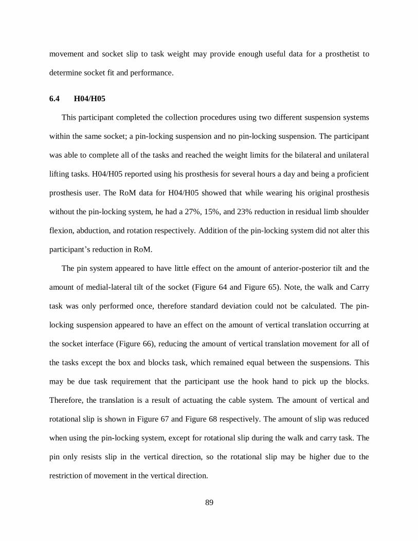
89
movement and socket slip to task weight may provide enough useful data for a prosthetist to
determine socket fit and performance.
6.4 H04/H05
This participant completed the collection procedures using two different suspension systems
within the same socket; a pin-locking suspension and no pin-locking suspension. The participant
was able to complete all of the tasks and reached the weight limits for the bilateral and unilateral
lifting tasks. H04/H05 reported using his prosthesis for several hours a day and being a proficient
prosthesis user. The RoM data for H04/H05 showed that while wearing his original prosthesis
without the pin-locking system, he had a 27%, 15%, and 23% reduction in residual limb shoulder
flexion, abduction, and rotation respectively. Addition of the pin-locking system did not alter this
participant’s reduction in RoM.
The pin system appeared to have little effect on the amount of anterior-posterior tilt and the
amount of medial-lateral tilt of the socket (Figure 64 and Figure 65). Note, the walk and Carry
task was only performed once, therefore standard deviation could not be calculated. The pin-
locking suspension appeared to have an effect on the amount of vertical translation occurring at
the socket interface (Figure 66), reducing the amount of vertical translation movement for all of
the tasks except the box and blocks task, which remained equal between the suspensions. This
may be due task requirement that the participant use the hook hand to pick up the blocks.
Therefore, the translation is a result of actuating the cable system. The amount of vertical and
rotational slip is shown in Figure 67 and Figure 68 respectively. The amount of slip was reduced
when using the pin-locking system, except for rotational slip during the walk and carry task. The
pin only resists slip in the vertical direction, so the rotational slip may be higher due to the
restriction of movement in the vertical direction.

90
Figure 64: H04/H05 anterior-posterior socket tilt for the original prosthesis with and without using the pin-
locking system.
Figure 65: H04/H05 medial-lateral socket tilt for the original prosthesis with and without using the pin-
locking system.

91
Figure 66: H04/H05 proximal-distal translation for the original prosthesis with and without using the pin-
locking system.
Figure 67: Vertical slip for the sensor embedded prosthesis using the two suspension systems.

92
Figure 68: Rotational slip for the sensor embedded prosthesis using the two suspension systems.
The linear regression correlations made for this participant only include data that would be
included in a standardized dynamic socket fit procedure proposed and discussed in the next
chapter. The data used in the correlation figures only uses the data points from the bilateral and
unilateral lifting tasks, and only four correlations are presented. The author believe the tasks
provide the most data, as discussed in the sections for participants above, and the two lifting
tasks provide a range of weights and residual limb movements that will give the prosthetist
enough data to evaluate the socket fit. Figure 69 shows the correlation between anterior-posterior
tilt of the socket and the amount of residual limb movement, which was significant for both
suspension systems (p<0.0001). The same correlation plot was made for the amount of medial-
lateral tilt of the socket (Figure 70), and a significant correlation was found for both suspension
systems when correlating to residual limb RoM (p<0.0001).
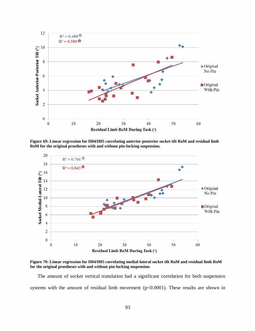
93
Figure 69: Linear regression for H04/H05 correlating anterior-posterior socket tilt RoM and residual limb
RoM for the original prostheses with and without pin-locking suspension.
Figure 70: Linear regression for H04/H05 correlating medial-lateral socket tilt RoM and residual limb RoM
for the original prostheses with and without pin-locking suspension.
The amount of socket vertical translation had a significant correlation for both suspension
systems with the amount of residual limb movement (p<0.0001). These results are shown in

94
Figure 71. There was a significant correlation between the vertical slip and task weight for both
suspension systems (p<0.0001), but not rotational slip. These correlations plots are shown in
Figure 72.
Figure 71: Linear regression for H04/H05 correlating vertical socket translation RoM and residual limb RoM
for the original prostheses with and without pin-locking suspension.
Figure 72: Linear regression for H04/H05 correlating vertical and rotational slip RoM and the weight of each
task for the sensor embedded prostheses with and without pin-locking suspension.
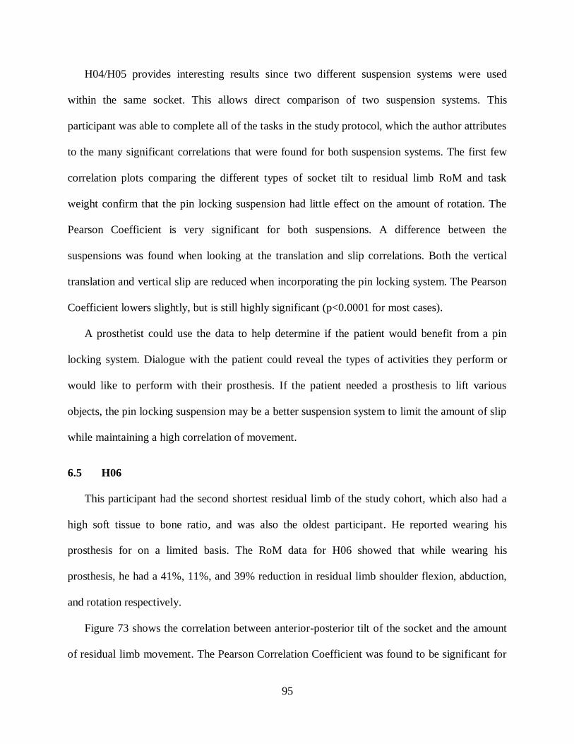
95
H04/H05 provides interesting results since two different suspension systems were used
within the same socket. This allows direct comparison of two suspension systems. This
participant was able to complete all of the tasks in the study protocol, which the author attributes
to the many significant correlations that were found for both suspension systems. The first few
correlation plots comparing the different types of socket tilt to residual limb RoM and task
weight confirm that the pin locking suspension had little effect on the amount of rotation. The
Pearson Coefficient is very significant for both suspensions. A difference between the
suspensions was found when looking at the translation and slip correlations. Both the vertical
translation and vertical slip are reduced when incorporating the pin locking system. The Pearson
Coefficient lowers slightly, but is still highly significant (p<0.0001 for most cases).
A prosthetist could use the data to help determine if the patient would benefit from a pin
locking system. Dialogue with the patient could reveal the types of activities they perform or
would like to perform with their prosthesis. If the patient needed a prosthesis to lift various
objects, the pin locking suspension may be a better suspension system to limit the amount of slip
while maintaining a high correlation of movement.
6.5 H06
This participant had the second shortest residual limb of the study cohort, which also had a
high soft tissue to bone ratio, and was also the oldest participant. He reported wearing his
prosthesis for on a limited basis. The RoM data for H06 showed that while wearing his
prosthesis, he had a 41%, 11%, and 39% reduction in residual limb shoulder flexion, abduction,
and rotation respectively.
Figure 73 shows the correlation between anterior-posterior tilt of the socket and the amount
of residual limb movement. The Pearson Correlation Coefficient was found to be significant for
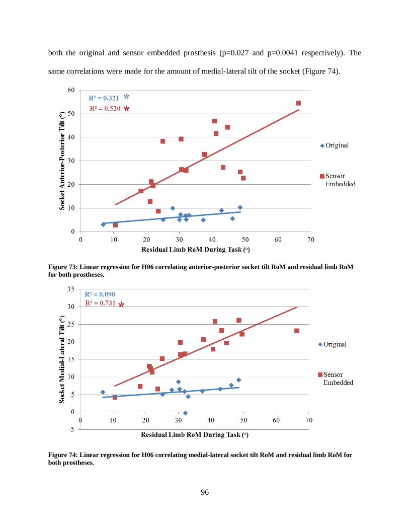
96
both the original and sensor embedded prosthesis (p=0.027 and p=0.0041 respectively). The
same correlations were made for the amount of medial-lateral tilt of the socket (Figure 74).
Figure 73: Linear regression for H06 correlating anterior-posterior socket tilt RoM and residual limb RoM
for both prostheses.
Figure 74: Linear regression for H06 correlating medial-lateral socket tilt RoM and residual limb RoM for
both prostheses.
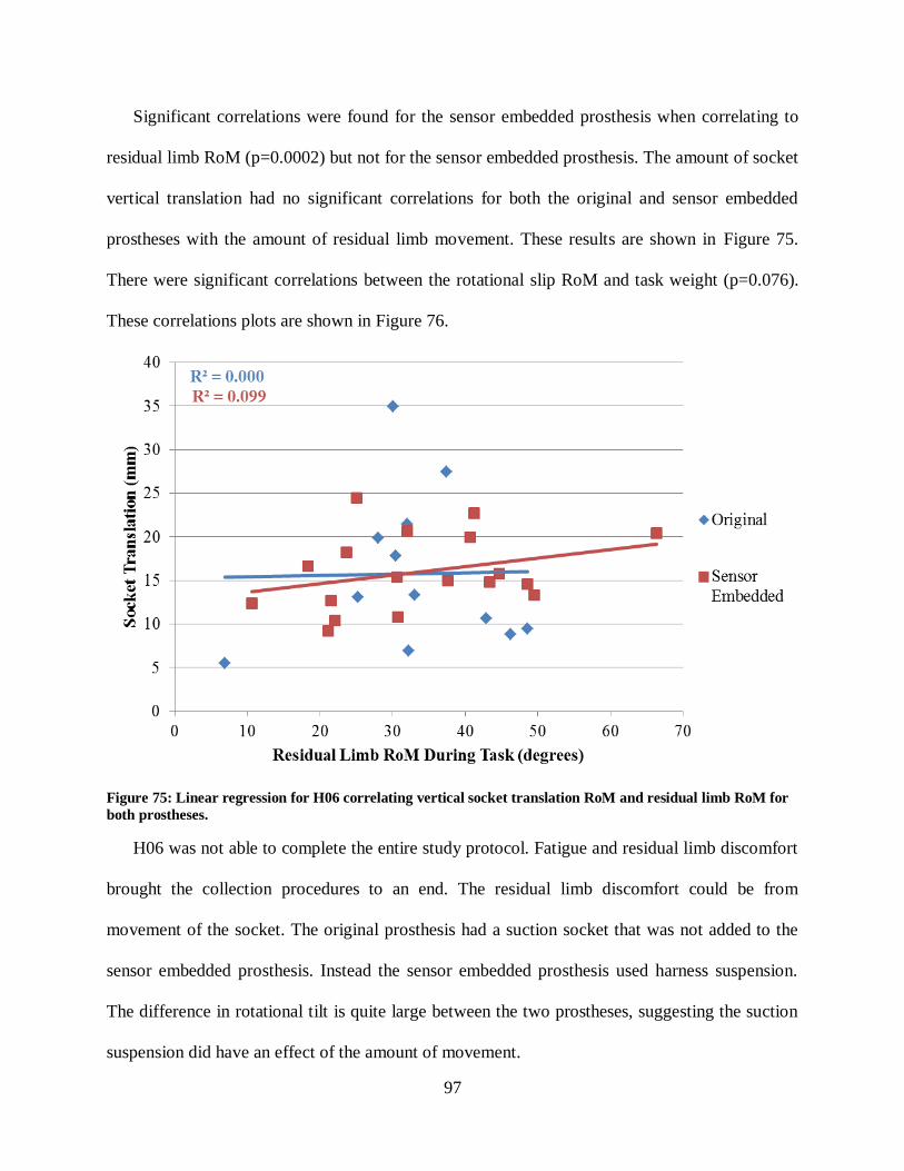
97
Significant correlations were found for the sensor embedded prosthesis when correlating to
residual limb RoM (p=0.0002) but not for the sensor embedded prosthesis. The amount of socket
vertical translation had no significant correlations for both the original and sensor embedded
prostheses with the amount of residual limb movement. These results are shown in Figure 75.
There were significant correlations between the rotational slip RoM and task weight (p=0.076).
These correlations plots are shown in Figure 76.
Figure 75: Linear regression for H06 correlating vertical socket translation RoM and residual limb RoM for
both prostheses.
H06 was not able to complete the entire study protocol. Fatigue and residual limb discomfort
brought the collection procedures to an end. The residual limb discomfort could be from
movement of the socket. The original prosthesis had a suction socket that was not added to the
sensor embedded prosthesis. Instead the sensor embedded prosthesis used harness suspension.
The difference in rotational tilt is quite large between the two prostheses, suggesting the suction
suspension did have an effect of the amount of movement.

98
Figure 76: Linear regression for H06 correlating socket slip RoM and the weight of each task for the sensor
embedded prostheses.
The amount of vertical translation and slip seems to be sporadic, even though significant
correlations were found for the amount of slip. A prosthetist could use the data to redesign the
socket shape by making the correlations higher among all measures. The prosthetist could use
their experience to find ways to make the socket translation more predictable as well as reduce
the magnitude of movement. The prosthetist could also try different suspension system to see
what would help limit motion and tailor the socket shape to provide a high correlation of
movement.
6.6 H07
This participant had the second longest residual limb of the study cohort. H07 came to a
prosthetist in Tampa, seeking a new prosthesis due to dissatisfaction with his existing system. He
agreed to participate in this study while his new myoelectric arm was being made. He described

99
the socket as uncomfortable, and it was visually loose at the proximal end of the residual limb,
having a gap between one to two inches between the socket wall and skin surface. The RoM data
for this participant showed that while wearing his prosthesis, he had a 17%, 17%, and 0%
reduction in residual limb shoulder flexion, abduction, and rotation respectively. This was still
considered a large reduction in shoulder RoM, especially considering the residual limb length of
H07.
Similar to H04/H05, the linear regression correlations made for this participant only include
data that would be included in a standardized dynamic socket fit procedure proposed and
discussed in the next chapter. The data used in the correlation figures only uses the data points
from the bilateral and unilateral lifting tasks, and only four correlations are presented. The author
believe the tasks provide the most data, as discussed in the sections for participants above, and
the two lifting tasks provide a range of weights and residual limb movements that will give the
prosthetist enough data to evaluate the socket fit. Figure 77 shows the correlation between
anterior-posterior tilt of the socket and the amount of residual limb movement. The Pearson
Correlation Coefficient was found to be significant for both the original and sensor embedded
prosthesis (p=0.016 and p<0.0001 respectively). The same correlation figure was made for the
amount of medial-lateral tilt of the socket, and a significant correlation was found for the sensor
embedded prosthesis when correlating to residual limb movement (p=0.0094) (Figure 78). The
amount of socket vertical translation had a significant correlation for the sensor embedded
prosthesis with the amount of residual limb movement (p<0.0001) (Figure 79). The amount of
socket slip was assessed for the sensor embedded prosthesis only. There were no significant
correlations between the vertical and rotational slip RoM and the residual limb RoM and are
shown in Figure 80.

100
Figure 77: Linear regression for H07 correlating anterior-posterior socket tilt RoM and residual limb RoM
for both prostheses.
Figure 78: Linear regression for H07 correlating medial-lateral socket tilt RoM and residual limb RoM for
both prostheses.
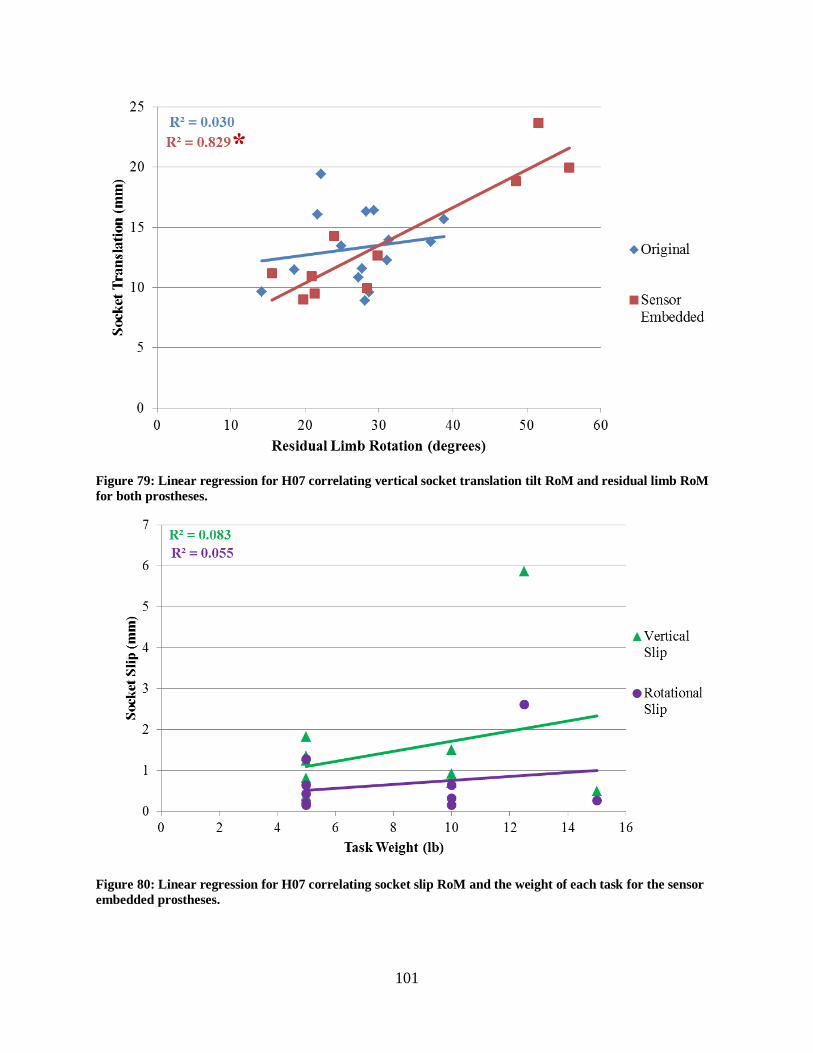
101
Figure 79: Linear regression for H07 correlating vertical socket translation tilt RoM and residual limb RoM
for both prostheses.
Figure 80: Linear regression for H07 correlating socket slip RoM and the weight of each task for the sensor
embedded prostheses.

102
H07 had a high level of dissatisfaction with their socket and prosthesis. He was unable to
complete the same tasks with both arms, due to discomfort developing in the residual limb.
Therefore the protocol was stopped. The results above show that the socket had few correlations
for the original prosthesis, suggesting the socket does not have a good fit with the residual limb.
The sensor embedded prosthesis had higher correlations but may be related to the universal
harness system that was used in the study. If a socket shape is not providing a suspension, the
harness will have more of an influence on socket interface movement. The graphs show that the
medial –lateral direction is worse than the anterior-posterior direction in terms of how the socket
moves. The magnitude of movement in the two directions is roughly the same, but the anterior-
posterior movement is more predictable, thus having a higher correlation. The prosthetist could
use that data to develop a more medial-laterally stable socket.
103
CHAPTER 7: DISCUSSION AND LIMITATIONS
The motion capture model and Slip Detection Sensor provided a method of measurement to
quantify movement between the residual limb and prosthetic socket, including rotations,
translations, and slip. Data were collected on six transhumeral amputee participants. The study
showed that the movement occurring at the socket interface is very dependent on the participant
and his particular suspension system. The results of the TAPES survey provided a self-reported
level of satisfaction with each participant’s prosthesis. The scores indicated that most of the
participants had adjusted to using a prosthesis and their limitation to participant in the particular
activities included in the questionnaire was spread over a wide range. A majority of the
participants rated socket comfort a 2/3 on the TAPES, regardless of how it performed during the
study protocol. However, two participants (H06 and H07) rated socket comfort and fit the lowest
score possible, a one out of three, and both had inconsistent movement during the study protocol
relative to the other participants. A more sensitive survey utilizing a five or ten point scale may
be needed however. Additional questions focusing on socket fit, comfort, and amputee perceived
socket movement could provide more information for researchers.
The average socket movements for each task were shown in Figure 37 through Figure 41.
The largest anterior-posterior and medial-lateral tilts were found for the bilateral and unilateral
lifting tasks. The largest vertical socket translations were found for the bilateral, unilateral, and
walk and carry task. The walk and carry task had a lot of translation and slip, but was most likely
due to the length of the task which was one minute. The amount of socket tilts, translation, and

104
slips found for the box and blocks, folding a towel, and walk and carry task were relatively
equal. The amounts of various movements were also correlated to two different task outcomes,
the range of residual limb angle during task completion and the weight of each task.
The amount of vertical and rotational slip was measured to be relatively small magnitudes of
movement, on the order of millimeters, relative to the overall movement of the prosthesis. This
slip motion however will be important to understand and measure. While they did not result in
soft tissue injury during the course of the study, slip motion occurring throughout the course of
the day could have more detrimental effects on the soft tissues. Using the Slip Detection Sensor
as a measurement device, the amount of slip will be measured in order to provide more
comfortable sockets and improve residual limb health.
Only two of the six participants in the study, H03 and H04/H05, were able to complete all of
the tasks. An additional participant, H02, would have been able to complete the procedures but
had a back issue and the study team decided to exclude the 50 pound bilateral lift. These three
participants had the strongest correlations between socket tilts and residual limb angle, vertical
socket translation and residual limb angle, and socket slip (both directions) and task weight. The
correlations for each of these three participants were much higher than the rest of the
participants, suggesting a possible relationship between these outcomes and the functional
performance of a socket/prosthesis. This result is quite interesting, and may provide an
interesting outcome for socket evaluation. The fact that this outcome is associated with the top
performers is not surprising after consideration. The high correlation shows that the socket
moves in a consistent manner (i.e. the same movement of the residual limb results in the same
movement of the socket). Therefore, the amputee can predict how his prosthesis will move as he
105
completes a task. The amputee can then establish what motions are uncomfortable or cause the
socket to put pressure in a sensitive area, and avoid them.
Traditional socket fit belief suggests that motion between the residual limb interface and
prosthetic socket should be limited and is the main focus of prosthetists during the fitting
process. However the specific threshold of movement that is acceptable in a final socket has not
been quantified. The results of the three participants able to complete the entire study protocol
suggest that not only should socket interface movement be limited, but it is equally important to
maximize the correlations for a few outcomes. This is highlighted by the results of H02, who had
one of the highest amounts of socket interface movement out of the study cohort and was still
able to have a very functional prosthesis based off H02’s ability to complete all but one of the
tasks. H02 did however have very significant correlations of movement to a number of the
outcomes including the various socket tilts and residual limb RoM, the vertical socket tilt and
residual limb RoM, and socket slip (both directions) and task weight, indicating the socket
moved in a consistent way.
7.1 Review of Hypotheses
The first hypothesis stated that “There would be a significant decrease in shoulder RoM
while wearing a prosthesis.” The RoM tasks found that there was not a significant difference for
shoulder flexion and abduction between the non-amputated limb and the residual limb without
wearing a prosthesis. This result indicates that without wearing a prosthesis, the participants of
this study were able to perform similar shoulder RoM with the residual limb as the non-
amputated limb. The results found a significant difference in shoulder rotation about the long
axis of the residual limb between the non-amputated limb and the residual limb without wearing
a prosthesis. The author believes this is a result of inherit error within the marker set. These

106
markers are placed on the skin surface and are good at detection flexion and abduction, but are
not precise at detecting rotation about the long axis of the intrinsic skeletal features of the
residual limb. The RoM for shoulder flexion and abduction was also significantly different
between the residual limb without a prosthesis and when the participants wore either the original
or sensor embedded prosthesis. Some of the participants had reductions in RoM upwards of 30+
degrees for some directions. This difference may be due to inefficiency in the socket’s ability to
transfer movements of the residual limb to the prosthesis. Again the shoulder rotation between
the residual limb without wearing a prosthesis and the residual limb with wearing each of the
prostheses was not significant, but may be due to the marker set’s inability to accurately detect
rotational movement of the residual limb.
The second hypothesis stated that “Participants with shorter residual limbs will have more
movement at the socket interface than participants with longer residual limbs.” Results from the
multivariate linear regression found a negative correlation coefficient when comparing residual
limb length to each of the different types of socket movement. A negative correlation coefficient
means an inverse relationship between the two factors. In other words, the shorter the residual
limb, the more movement that occurs at the socket interface. Significant correlations were found
for medial-lateral socket tilt, vertical socket slip, and rotational socket slip. The other two types
of socket movement, anterior-posterior socket tilt and vertical translation were not significant but
did have negative correlation coefficients.
The third hypothesis stated that “Task weight will be the biggest factor affecting the amount
of movement occurring at the socket interface.” Results from the multivariate linear regression
showed that task weight did impact the amount of socket interface movement. Task weight had
the most significant impact on vertical socket translation and vertical socket slip. However,

107
residual limb movement was found to have the most significant impact on all the types of socket
movement.
7.2 Comparison of Results to Other Socket Movement Studies
The movement occurring at the socket interface is highly dependent on the participant and
his/her socket and suspension system. The anterior-posterior tilt found in this study ranged from
about 3 degrees to 24 degrees and the medial-lateral tilt ranged from about 2 to 16 degrees of
movement. Very few studies on upper limb socket movement exist for comparison. Sensinger
[69] found anterior-posterior tilt RoM of the socket to be approximately 10 degrees. This was
found during static poses where the participant locked there prosthetic elbow at 90 degrees of
flexion and an oscillatory load was applied. The anterior posterior tilt in this study were higher in
magnitude but may be a result of examining dynamic activity, which incorporates more factors
such as movement of the residual limb, forces from the harness system, and other forces which
would increase the amount of movement experienced. Convery [64] used ultrasound to assess
socket rotations in lower limb systems during gait and found RoM of 12 and 17 degrees for
medial-lateral and anterior-posterior socket tilt respectively. This study was done on transtibial
amputees, which have more intrinsic bone for the socket to be designed around. These rotations
may increase at the transfemoral amputation level, but are still close to the magnitude of socket
tilt movement found in this dissertation.
Pistoning, or vertical translation has also been well documented for lower limb systems The
studies reviewed in Chapter 1 found pistoning ranging from 22 to 75 mm. This study had a range
of vertical translation of 2 to 16 mm. It is not unexpected that there is a large difference in the
range of movement, because lower limb prostheses are subjected to larger forces associated to
108
weight bearing and gait. The translation found in this study is not due to weight bearing, rather
operation of the prosthetic joints and forces associated with lifting various objects.
Appoldt measured 6 mm of slip during gait using a pen mounting onto a prosthetic socket of
below knee prostheses, but recognized the high error associated with the analysis of data. The
average of slip found for the walk and carry task was 12 mm for vertical slip and 7 mm for
rotational slip. A summary comparing the results of this dissertation to the results of previous
socket interface studies is shown in Table 9.
Table 9: Summary of comparison to other socket studies.
7.3 Clinical Impact
The prosthetic fitting process is currently highly subjective. The amputee is dependent on the
prosthetist’s skill and experience to produce a socket shape that provides a high level of comfort
and functional connection with the prosthesis. Without quantitative data that can help determine
when a proper socket shape has been made or an appropriate suspension method selected, the
prosthetist uses his/her judgment based off qualitative feedback from the amputee and an
Study Study Finding Dissertation Findings Reasoning
Sensinger
~10° anterior-
posterior socket
tilt
Average for 25lb bilateral
lift task was 12° but 23°
for highest individual
Comparing socket
movement during static
poses to dynamic activity
Convery
17° anterior-
posterior socket
tilt and 12° medial-
lateral socket tilt
Anterior-posterior tilt was
higher than medial-lateral
tilt
Magnitudes of movement
in each direction close
between studies
Pistoning
Studies
22-75 mm of
pistoning
Up to 50 mm of
translation
Expect lower limb to have
more pistoning movement
due to magnitude of load
Appoldt6 mm of slip with
pen
Highest average slip was
12 mm for vertical and 7
mm for rotational slip
Poor accuracy reading ink
trail
109
assessment of the residual limb. The methods and devices used in the study offer a way to
measure movement at the interface, which can improve the socket fitting and prescription
procedures.
First, the methods can be used to compare various socket types and suspension methods,
impacting the socket/suspension prescription process. Data can be collected on a number of
different design methodologies and suspension methods completing a series of tasks similar to
the ones performed for this study. With enough data collected, generalizations can be made for
how each socket design and suspension method affects movement at the interface and correlates
them to a number of patient parameters. The patient parameters could include residual limb
length and composition, and the activities they perform, the activities they would like to perform,
on a daily basis. This will provide a reference database that can assist a prosthetist when
prescribing a socket/suspension type for an individual. This will give the prosthetist quantitative
data to show the insurance company why an individual needs one suspension system over
another, and why the insurance should cover the potential cost increase for that system.
After socket prescription, the data can also be used to determine if an appropriate socket
shape has been made. Prosthetists could follow their current procedures up through production of
the first check socket. Using the check socket, the amputee could then perform a standardized
dynamic socket check discussed in the next section. Data similar to the results of this dissertation
will be collected during the dynamic socket check. The results will show the prosthetist how
much movement is occurring at the interface and in what direction the movement is occurring.
The prosthetist can then make a more informed decision on the changes that should be made to
the socket shape to improve the socket fit. For instance, data from the Slip Detection Sensor will
show the prosthetist how much slip is occurring during the dynamic socket check, and the

110
prosthetist can decrease the socket volume to create a snug fit and thereby reduce the amount of
socket slip. The correlation plots presented will also provide information on how the socket is
performing, and can be used in conjunction with the actual movement data for each task. The
data could reduce the number of check sockets made while producing a better socket for the
amputee. Therefore, prosthetic care costs could be lowered by reducing prosthetist time and
material costs, as well as reducing the number of visits due to comfort related issues.
Another clinical impact would be the creation of an automated dynamic interface using the
Slip Detection Sensor as a control device. A range of “allowable” slip will be programmed into
the software, and data from the Slip Detection Sensor will be used to measure the amount of slip
at the interface. If the sensor detects slip that is above the allowable range, the dynamic interface
system would automatically adjust the interface settings to correct for excess slip movement.
One possible system would be the LimbLogic system described earlier [30]. This is an adjustable
vacuum system that is currently controlled by the amputee. Incorporating the Slip Detection
Sensor with this system removes the user from the loop and may provide better comfort and
reduce soft tissue irritation through better interface management.
Lastly, challenges with insurance coverage are another big problem in the prosthetic industry.
All of the clinical impacts described in this section relate to this issue. The insurance companies
may not be willing to pay for a new socket type if the cost is too great. However, using the
measurement method developed in this dissertation could provide quantitative data for why one
socket design is superior to another and how it can improve residual limb health over time,
presenting evidence for why the insurance companies should cover the initial increased cost.

111
7.4 Standardization of the Socket Fitting Procedures
Tampa, Florida and the surrounding cities are fortunate to have capable and knowledgeable
prosthetists providing excellent prosthetic care. The local VA hospital, a regional provider of
prosthetic care, helps attract these talented professionals. However, other parts of the country and
world are not as fortunate. Socket fitting and prescription therefore varies widely geographically.
Developing a formal socket fitting procedure will standardize the fitting process in hopes of
improving the end result, providing comfortable and functional prostheses.
The procedures of this study could be used as a basis for the standardized socket check,
making some adjustments to provide more control of the variables. After forming the
thermoplastic socket, the prosthetist could attach a lever arm to the distal end of the socket. This
lever arm would be mounted between a 45 and 90 degree flexion angle to simulate elbow
flexion. The end of the lever arm would include a hook that the amputee could use to pick up a
series of weighted objects while the same movement data are collected. The unilateral and
bilateral lifting tasks could be the only tasks included during the dynamic socket check, and
would provide enough data for the prosthetist to analyze and make adjustments to socket shape
from.
The methods of this dissertation used a motion analysis system and Slip Detection Sensor.
The slip sensor could easily afforded by local prosthetic clinics, but the motion capture system
could be too expensive. Therefore the slip sensor could be used alone, or other hardware could
be used to replace the motion capture system. One study found comparable results between
accelerometer based sensors and a motion capture system [73]. This may provide a less
expensive solution for local prosthetic clinics. The prosthetist could evaluate the skin blanching
112
through the clear thermoplastic socket as they currently do, then analyze the socket movement
data and correlations to help determine what changes to make for the next socket iteration.
A number of correlation graphs were presented in the results, but only a few will be needed
to analyze the socket. This includes anterior-posterior socket tilt, medial-lateral socket tilt, and
vertical socket translation to residual limb RoM during the task. Vertical socket translation and
vertical/rotational socket slip to the task weight were also significant correlations that could be
used as performance parameters. These outcomes seemed to have the highest correlations and
provided the most information for how a socket was performing. Comparing the participants to
one another, it was shown that the three participants who were able to complete the entire study
protocol also had very significant correlations to each of these comparisons.
7.5 Limitations
The small sample size of the study limits the power of the results and should be addressed in
future studies. However, the sample size of seven is greater than most of the upper limb
prosthesis studies currently in the literature, particularly for transhumeral prostheses. The motion
capture model assumption that the socket anterior-posterior and medial-lateral tilt rotates about
the center point of bone inside the socket has not been proven experimentally. Additionally, each
participant’s socket shape was duplicated, but not the rest of the prosthetic components and
harness system. Standard body-powered components and a universal harness were used. The
universal harness could easily be adjusted for any size user. This may have created differences in
how the participant operated the prosthesis and how the socket movement was influenced by the
harness. It was not possible to determine if the difference in socket movement was due to
differences in the socket shape and which were due to difference in the prosthesis and harness

113
system. For this reason, the sample was problematic to study. Testing of other amputation levels
and prosthetic systems will be needed to further validate the methods.
Another limitation of the study was human error in placing the passive reflective markers on
the participants and their prosthesis. While great care was taken to standardize placement
procedures, it was not possible to place the markers at exactly the same location. A relatively
small sample size was collected, and therefore these results are related to these individuals. More
data are needed before general conclusions can be made.

114
CHAPTER 8: CONTRIBUTIONS AND FUTURE WORK
The motion capture model and Slip Detection Sensor developed in this dissertation allowed
for the measurement of socket interface movement during dynamic activity. The data collected
on seven transhumeral amputees represents one of the largest sample sizes in the current
literature. Additional participants are needed to increase the power of the study. A few
conclusions can made based of the results from the study sample. Wearing a prosthesis on the
residual limb significantly reduced the shoulder range of motion for flexion/extension and
abduction/adduction compared to when the participant was not wearing a prosthesis. The amount
of socket anterior-posterior and medial-lateral tilt was not dependent on the task weight as
hypothesized, rather was correlated with residual limb movement. The amount of socket slip was
more dependent on the task weight. The length of the participants’ residual limb also had an
impact on the amount of socket interface movement. A multivariate linear regression found a
negative correlation value when comparing residual limb length to the different types of socket
movement. Therefore shorter residual limbs resulted in more movement at the socket interface.
The magnitude of socket slip was relatively small, but throughout the course of the day, the
cumulative effect of the slip motion over hours (rather than minutes or seconds like the tasks in
this study) could result in residual limb injury. The Slip Detection Sensor proved to be an
efficient and nonintrusive means to quantify the amount of socket slip occurring at the socket
interface, which is projected to be easily adaptable for incorporation to adjustable interface

115
systems. Therefore the Slip Detection Sensor will be critical to the advancement of socket
comfort and performance.
8.1 Contributions
The work in this dissertation has made several contributions to the areas of basic and applied
prosthetic socket interface research.
1) A motion capture model was developed to quantify the amount of prosthetic socket
rotations and translation occurring at the interface with the residual limb.
2) A Slip Detection Sensor was designed, prototyped, and validated to experimentally
measure the amount of slip between the prosthetic socket and residual limb skin surface.
3) The amount of socket interface movement occurring for body-powered transhumeral
prosthesis wearers during common tasks was quantified.
4) Evidence was provided for the tasks that should be included in a dynamic socket fit check
that could be used to standardize prosthetic care across the world.
5) Potential socket fit outcomes were discovered that can be used to evaluate the fit of a
socket.
The methods developed in this dissertation could be applied in research and clinical settings.
Researchers will be able to evaluate the fit and performance of various socket designs/suspension
methods, providing clinicians with quantified data on how one socket and suspension option
could provide improved comfort and function over another socket and suspension option based
off some amputee specific parameters. The development of automatic adjusting socket interfaces
will be another avenue for Slip Detection Sensor to positively impact prosthetic comfort.
Clinicians can use the data to assist them with the fitting and prescription of prosthetic sockets.

116
8.2 Future Work
Continued research investigating movements occurring at the prosthetic socket interface is
needed. The work presented here indicates other factors that contribute to socket interface
movement that could be investigated.
First, the motion capture method for approximating residual limb bone position inside the
socket could be compared to fluoroscopy or some type of radiological measurement technique.
This will show the accuracy at which the method approximates the bone position inside the
socket. The procedures would be limited to static poses where the amputee will hold weighted
objects with his prosthesis and the amount of socket tilt and socket translation measured.
Second, additional sensors could be used such as strain gages in the harness suspension
system to quantify forces being placed on the socket by the harness straps. The data from the
sensor embedded prosthesis showed higher correlations for the three participants who were not
able to complete the study protocol than the data from the original prosthesis did. This may be
related to additional suspension of the universal harness used with all of the sensor embedded
prostheses. Additionally, myoelectric devices could be included in the study to see the difference
in socket interface movement with and without a harness suspension system or the need to put
tension in the cables to operate the prosthesis.
Third, the simultaneous use of multiple Slip Detection Sensors placed at various positions in
the socket would provide an overall slip mapping occurring at the socket interface. The various
positions could be compared to see at what point(s) the most amount of slip occurs. This data
could be used to optimize the location of the sensor for use in a dynamic interface system. The
Slip Detection Sensor can be further reduced in size and operational efficiency for incorporation

117
with a dynamic interface system. The system could be tested to see how it improves residual
limb health and socket by managing socket interface movement.
These methods have currently been tested only on one level of upper limb systems, but could
easily be expanded to lower limb prostheses. One hot area of research relates to the amount of
pistoning in lower limb systems. This would be an excellent application for the Slip Detection
Sensor. The sensor could even be used in a study to assess how the Slip Detection Sensor
impacts a prosthetists decision making during a fitting for lower limb system. A dynamic socket
check can be performed where the slip sensor collects data while the amputee ambulates with a
check socket. Additional work pertaining to the slip detection sensor includes simplifying the
software outcomes for ease of clinical use.
The methods and devices presented in this study offer an elegant approach to analyze the
socket interface movement. The results from this study and related future work hope to improve
socket comfort and prosthetic function to meet the needs of an constantly growing amputee
population.
118
REFERENCES
1. Dudek, N.L., et al., Dermatologic conditions associated with use of a lower-extremity
prosthesis. Archives of physical medicine and rehabilitation, 2005. 86(4): p. 659-663.
2. Highsmith, M.J., J.T. Highsmith, and J.T. Kahle, Identifying and Managing Skin Issues
With Lower-Limb Prosthetic Use. inMotion January/February, 2011. 21(1): p. 41-43.
3. Lake, C., The evolution of upper limb prosthetic socket design. JPO: Journal of
Prosthetics and Orthotics, 2008. 20(3): p. 85.
4. Schultz, A.E., S.P. Baade, and T.A. Kuiken, Expert opinions on success factors for
upper-limb prostheses. Journal of Rehabilitation Research and Development, 2007.
44(4): p. 483.
5. Legro, M.W., et al., Issues of importance reported by persons with lower limb
amputations and prostheses. Journal of Rehabilitation Research and Development, 1999.
36(3).
6. Ziegler-Graham, K., et al., Estimating the prevalence of limb loss in the United States:
2005 to 2050. Archives of physical medicine and rehabilitation, 2008. 89(3): p. 422-429.
7. Stansbury, L.G., et al., Amputations in US military personnel in the current conflicts in
Afghanistan and Iraq. Journal of orthopaedic trauma, 2008. 22(1): p. 43.
8. Stinner, D.J., et al., Prevalence of Late Amputations During the Current Conflicts in
Afghanistan and Iraq. Military Medicine, 2010. 175(12): p. 1027-1029.
9. Fischer, H. US Military casualty statistics: operation new dawn, operation Iraqi freedom,
and operation enduring freedom. 2010. DTIC Document.
10. Pezzin, L.E., et al., Use and satisfaction with prosthetic limb devices and related services.
Archives of physical medicine and rehabilitation, 2004. 85(5): p. 723-729.
11. Biddiss, E.A. and T.T. Chau, Upper limb prosthesis use and abandonment: A survey of
the last 25 years. Prosthetics and Orthotics International, 2007. 31(3): p. 236-257.
12. Resnik, L., et al., Advanced Upper Limb Prosthetic Devices: Implications for Upper
Limb Prosthetic Rehabilitation. Archives of physical medicine and rehabilitation, 2012.
93(4): p. 710-717.
119
13. Raichle, K.A., et al., Prosthesis use in persons with lower-and upper-limb amputation.
Journal of Rehabilitation Research and Development, 2008. 45(7): p. 961.
14. McFarland, L.V., et al., Unilateral upper-limb loss: satisfaction and prosthetic-device use
in veterans and servicemembers from Vietnam and OIF/OEF conflicts. J Rehabil Res
Dev, 2010. 47(4): p. 299-316.
15. Blough, D.K., et al., Prosthetic cost projections for servicemembers with major limb loss
from Vietnam and OIF/OEF, 2010, DTIC Document.
16. Gram, D. Amputees fight Caps in Coverage for Prosthetics. USA Today, 2008.
17. Lura, D.J., The Creation of a Robotics Based Human Upper Body Model for Predictive
Simulation of Prostheses Performance. 2012.
18. Colorado, U.o. Module 10: Upper Limb Prostheses. 2006; Available from:
http://elc.cu.edu.eg/elcmoodledata/21/prostheses/F.P/M10.htm#Contents.
19. Childress, D., J. Billock, and R. Thompson, A Search for Better Limbs: Prosthetics
Research at Northwestern University. State of Effort- Research at NU: p. 200-212.
20. Farrell, T.R., et al., The effects of static friction and backlash on extended physiological
proprioception control of a powered prosthesis. Journal of Rehabilitation Research and
Development, 2005. 42(3): p. 327.
21. Alley, R.D., et al., Prosthetic sockets stabilized by alternating areas of tissue
compression and release. Journal of Rehabilitation Research and Development, 2011.
48(6).
22. Alley, R., Biomechanical Discussion of Current and Emergent Upper-Limb Prosthetic
Interface Designs. The Academy Today, 2009. 5(3).
23. Alley, R. The High-Fidelity Interface: Skeletal Stabilization through Alternating Soft
Tissue Compression and Release. 2011. Myoelectric Symposium.
24. Technology, B. RevoFit: Control Your Comfort. 2013; Available from:
http://www.revolimb.com/.
25. Heim, M., et al., Silicone Suspension of External Prostheses A New Era In Artificial Limb
Usage. Journal of Bone & Joint Surgery, British Volume, 1997. 79(4): p. 638-640.
26. Sanders, J.E. and S. Fatone, Residual limb volume change: Systematic review of
measurement and management. J Rehabil Res Dev, 2011. 48(8): p. 949-86.
27. Klute, G.K., et al., Vacuum-assisted socket suspension compared with pin suspension for
lower extremity amputees: effect on fit, activity, and limb volume. Archives of physical
medicine and rehabilitation, 2011. 92(10): p. 1570-1575.
120
28. Gholizadeh, H., N.A. Abu Osman, and A. Eshraghi, Effect of Vacuum-Assisted Socket
and Pin Suspensions on Socket Fit. Archives of physical medicine and rehabilitation,
2012. 93(5): p. 921.
29. Prosthetics. Introducing SmartPuck. 2013; Available from:
http://www.5280prosthetics.com/smartpuck/.
30. WillowWood. The Evloution of LimbLogic Provides Elevated Vacuum in an Easier to
Use System. 2013 7/17/2013]; Available from: http://www.willowwoodco.com/products-
and-services/elevated-vacuum/limblogic.
31. Hagberg, K., et al., Osseointegrated trans-femoral amputation prostheses: prospective
results of general and condition-specific quality of life in 18 patients at 2-year follow-up.
Prosthetics and Orthotics International, 2008. 32(1): p. 29-41.
32. Hagberg, K., et al., Socket versus bone-anchored trans-femoral prostheses: hip range of
motion and sitting comfort. Prosthetics and Orthotics International, 2005. 29(2): p. 153-
163.
33. Hagberg, K. and R. Brånemark, One hundred patients treated with osseointegrated
transfemoral amputation prostheses—rehabilitation perspective. J Rehabil Res Dev,
2009. 46(3): p. 331-44.
34. Tillander, J., Osseointegrated titanium implants for limb prostheses attachments:
infectious complications. Clinical Orthopaedics and Related Research®, 2010. 468(10):
p. 2781-2788.
35. Goldstein, B. and J. Sanders, Skin response to repetitive mechanical stress: a new
experimental model in pig. Archives of physical medicine and rehabilitation, 1998. 79(3):
p. 265-272.
36. Mak, A., M. Zhang, and D.A. Boone, State-of-the-art research in lower-limb prosthetic
biomechanics-socket interface: a review. Journal of Rehabilitation Research and
Development, 2001. 38(2): p. 161-174.
37. Sanders, J., Stump-Socket Interface Conditions. Pressure ulcer research: current and
future perspectives, 2005: p. 129.
38. Holloway, G., et al., Effects of external pressure loading on human skin blood flow
measured by 133Xe clearance. Journal of Applied Physiology, 1976. 40(4): p. 597-600.
39. Uustal, H., Prosthetic rehabilitation issues in the diabetic and dysvascular amputee.
Physical medicine and rehabilitation clinics of North America, 2009. 20(4): p. 689.
40. Schmalz, T., S. Blumentritt, and B. Marx, Biomechanical analysis of stair ambulation in
lower limb amputees. Gait & posture, 2007. 25(2): p. 267-278.

121
41. Alimusaj, M., et al., Kinematics and kinetics with an adaptive ankle foot system during
stair ambulation of transtibial amputees. Gait & posture, 2009. 30(3): p. 356-363.
42. Su, P.F., et al., Gait characteristics of persons with bilateral transtibial amputations.
Journal of Rehabilitation Research and Development, 2007. 44(4): p. 491-501.
43. White, H., et al., Bilateral kinematic and kinetic data of two prosthetic designs: a case
study. JPO: Journal of Prosthetics and Orthotics, 2001. 12(4): p. 120.
44. Silverman, A.K., et al., Compensatory mechanisms in below-knee amputee gait in
response to increasing steady-state walking speeds. Gait & posture, 2008. 28(4): p. 602-
609.
45. Beyaert, C., et al., Compensatory mechanism involving the knee joint of the intact limb
during gait in unilateral below-knee amputees. Gait & posture, 2008. 28(2): p. 278-284.
46. Carey, S.L., et al., Compensatory movements of transradial prosthesis users during
common tasks, in Clinical Biomechanics2008. p. 1128-1135.
47. Barnett, C., et al., Kinematic gait adaptations in unilateral transtibial amputees during
rehabilitation. Prosthetics and Orthotics International, 2009. 33(2): p. 135-147.
48. Dumas, R., L. Cheze, and L. Frossard, Loading applied on prosthetic knee of
transfemoral amputee: Comparison of inverse dynamics and direct measurements. Gait
& posture, 2009. 30(4): p. 560-562.
49. Blumentritt, S., T. Schmalz, and R. Jarasch, The safety of C-Leg: Biomechanical tests.
JPO: Journal of Prosthetics and Orthotics, 2009. 21(1): p. 2.
50. Dillon, M.P., T.M. Barker, and G. Pettet, Effect of inaccuracies in anthropometric data
and linked-segment inverse dynamic modeling on kinetics of gait in persons with partial
foot amputation. J Rehabil Res Dev, 2008. 45(9): p. 1303-1316.
51. Highsmith, M.J., et al., Kinematic evaluation of terminal devices for kayaking with upper
extremity amputation. JPO: Journal of Prosthetics and Orthotics, 2007. 19(3): p. 84.
52. Gholizadeh, H., et al., Transtibial prosthetic socket pistoning: Static evaluation of Seal-
In® X5 and Dermo® Liner using motion analysis system. Clinical Biomechanics, 2011.
53. Freilich, R., Biomechanical model of transhumeral prostheses. University of South
Florida, 2009: p. Masters Thesis.
54. Zhang, M., et al., Development of a non-linear finite element modelling of the below-knee
prosthetic socket interface. Medical engineering & physics, 1995. 17(8): p. 559-566.

122
55. Zhang, M. and A.F.T. Mak, A finite element analysis of the load transfer between an
above-knee residual limb and its prosthetic socket-roles of interface friction and distal-
end boundary conditions. Rehabilitation Engineering, IEEE Transactions on, 1996. 4(4):
p. 337-346.
56. Silver-Thorn, M.B. and D.S. Childress, Parametric analysis using the finite element
method to investigate prosthetic interface stresses for persons with trans-tibial
amputation. Journal of Rehabilitation Research and Development, 1996. 33: p. 227-238.
57. Sanders, J.E. and C.H. Daly, Normal and shear stresses on a residual limb in a prosthetic
socket during ambulation: comparison of finite element results with experimental
measurements. Journal of Rehabilitation Research and Development, 1993. 30: p. 191-
191.
58. Reynolds, D. and M. Lord, Interface load analysis for computer-aided design of below-
knee prosthetic sockets. Medical and Biological Engineering and Computing, 1992.
30(4): p. 419-426.
59. Quesada, P. and H.B. Skinner, Analysis of a below-knee patellar tendon-bearing
prosthesis: a finite element study. J Rehabil Res Dev, 1991. 28(3): p. 1-12.
60. Daly, W., et al., Skin-Socket Interface Pressure Of An Upper Limb Prosthesis:
Preliminary Findings.
61. Söderberg, B., L. Ryd, and B.M. Persson, Roentgen stereophotogrammetric analysis of
motion between the bone and the socket in a transtibial amputation prosthesis: a case
study. JPO: Journal of Prosthetics and Orthotics, 2003. 15(3): p. 95.
62. Grevsten, S. and U. Erikson, A roentgenological study of the stump-socket contact and
skeletal displacement in the PTB-Suction Prosthesis. Upsala Journal of Medical Sciences,
1975. 80(1): p. 49-57.
63. Kahle, J.T., A case study using fluoroscope to determine the vital elements of
transfemoral interface design. JPO: Journal of Prosthetics and Orthotics, 2002. 14(3): p.
121.
64. Lilja, M., T. Johansson, and T. Öberg, Movement of the tibial end in a PTB prosthesis
socket: a sagittal X-ray study of the PTB prosthesis. Prosthetics and Orthotics
International, 1993. 17(1): p. 21-26.
65. Papaioannou, G., et al., Assessment of amputee socket-stump-residual bone kinematics
during strenuous activities using Dynamic Roentgen Stereogrammetric Analysis. Journal
of biomechanics, 2010. 43(5): p. 871-878.
66. Convery, P. and K. Murray, Ultrasound study of the motion of the residual femur within a
trans-femoral socket during gait. Prosthetics and Orthotics International, 2000. 24(3): p.
226-232.

123
67. Sanders, J.E., et al., A noncontact sensor for measurement of distal residual-limb position
during walking. Journal of Rehabilitation Research and Development, 2006. 43(4): p.
509.
68. Commean, P.K., K.E. Smith, and M.W. Vannier, Lower extremity residual limb slippage
within the prosthesis. Archives of physical medicine and rehabilitation, 1997. 78(5): p.
476-485.
69. Sensinger, J.W. and R.F. Weir, Modeling and Preliminary Testing Socket-Residual Limb
Interface Stiffness of Above-Elbow Prostheses. Neural Systems and Rehabilitation
Engineering, IEEE Transactions on, 2008. 16(2): p. 184-190.
70. Appoldt, F.A., L. Bennett, and R. Contini, The results of slip measurements in above-
knee suction sockets. Bull Prosthet Res. Fall, 1968: p. 106-112.
71. Moy, P., W. Tusit, and C. Gunnarsson. Tensile deformation of ballistic gelatin as a
function of loading rate. in Proceedings of the XIth International Congress and
Exposition June. 2008.
72. Gallagher, P. and M. MacLachlan, Development and psychometric evaluation of the
Trinity Amputation and Prosthesis Experience Scales (TAPES). Rehabilitation
Psychology, 2000. 45(2): p. 130.
73. Martori, A.L., A Wearable Motion Analysis System to Evaluate Gait Deviations. 2013.

124
APPENDICES

125
Appendix A: Data Collection Documents
A.1 Subject Measurement Form

126
Appendix A (Continued)
A.2 Day 1 Data Collection Checklist

127
Appendix A (Continued)
A.3 Day 2 Data Collection Checklist

128
Appendix A (Continued)
A.4 Trinity Amputation and Prosthesis Experience Scales (TAPES)

129
Appendix A (Continued)

130
Appendix A (Continued)

131
Appendix A (Continued)

132
Appendix A (Continued)

133
Appendix A (Continued)

134
Appendix A (Continued)

135
Appendix B: Matlab Code
B.1 SRiM.m
% Socket Model creation algorithm for the "Socket Residual Limb Interface Model" (SRiM)
% Written by Matthew M. Wernke 3/31/2011
% Requires the Robotics Toolbox (Peter Corke) and the c3d wrapper (Matthew
% R. Walker)
% Process the data for the No prosthesis trials
%Change cd to dissertation files
cd ('C:\Users\mwernke\Documents\MATLAB\Dissertation Files')
% Include c3d files at this location
path ([cd,'\SubFunctions'], path)
% Clear variables fADL the current workspace
clear all
% Close all open figure windows (plots)
close all
% Define the subject side of amputation to set up coordinate frames
% H01=R; H02=R; H03=L; H04=R; H05=R; H06=L; H07
amputation = 'R';
% Change directory to the ROMNP with NP folder of subjects(s)
cd ('C:\Users\mwernke\Documents\MATLAB\Dissertation Files\H07_DS\ROMNP')
% Load all of the *.c3d (motion trails) files
foldernfo = dir('*.c3d');
% Create the field for subject, in structure ROMNP, set the feild filenames
% to the names of the files in the folder.
ROMNP.filenames = char(foldernfo.name);
% Create a varible for the number of .c3d files in the folder
ROMNP.nfiles = size(ROMNP.filenames,1);
%Create empty arrays to be filled later with RoM data
ROMNP.RLMaxCompiled = [];
ROMNP.RLMinCompiled = [];
ROMNP.CLMaxCompiled = [];
ROMNP.CLMinCompiled = [];
ROMNP.RLThetaRoMCompiled = [];
ROMNP.CLThetaRoMCompiled = [];
% For all files in ROMNPNP of subject
for i=1:ROMNP.nfiles;
% Load c3d server.
newServer = c3dserver;
136
Appendix B (Continued)
% Open the c3d files
openc3d(newServer,0,ROMNP.filenames(i,:));
% Set variable name to name of current file
name = removewhite(ROMNP.filenames(i,:));
% Get all of the targets (makers) fROMNP the c3d server
newtarget = get3dtargets(newServer,1);
% Assign the targets to the trial feild
ROMNP.(name) = newtarget;
% Set the variable markers to all of the marker names
markers = fieldnames(ROMNP.(name));
% Set Nmarkers equal to the number of markers in the trial.
Nmarker = size(markers,1);
% Set Nsamples equal to the number of samples in the trial.
Nsamples = size(ROMNP.(name).T1,1);
% Filter the marker data
for j=1:Nmarker
if ~strcmpi(markers(j), 'units')
ROMNP.(name).(char(markers(j))) = ...
WMAfilter(21,getfield(ROMNP.(name), char(markers(j)), {1:Nsamples,1:3}));
end
end
% Create virtual points based on marker positions.
ROMNP.(name).UTOR = (ROMNP.(name).CLAV+ROMNP.(name).T1)/2;
ROMNP.(name).LTOR = (ROMNP.(name).STRN+ROMNP.(name).T10)/2;
ROMNP.(name).rSHO = (ROMNP.(name).RSHOA+ROMNP.(name).RSHOP)/2;
ROMNP.(name).lSHO = (ROMNP.(name).LSHOA+ROMNP.(name).LSHOP)/2;
ROMNP.(name).RSL = (ROMNP.(name).RSLA+ROMNP.(name).RSLP)/2;
% Create the segment frames that do not change using createSegment.m
ROMNP.(name).Torso = createSegment(ROMNP.(name).UTOR,(ROMNP.(name).UTOR-
ROMNP.(name).LTOR),(ROMNP.(name).T1-ROMNP.(name).CLAV), 'yzx');
ROMNP.(name).RShoulder = createSegment(ROMNP.(name).rSHO,(ROMNP.(name).rSHO-
ROMNP.(name).UTOR),(ROMNP.(name).RSHOA-ROMNP.(name).RSHOP), 'zyx');
ROMNP.(name).LShoulder = createSegment(ROMNP.(name).lSHO,(ROMNP.(name).lSHO-
ROMNP.(name).UTOR),(ROMNP.(name).LSHOP-ROMNP.(name).LSHOA), 'zyx');
% Create the segment frames that do change using createSegment.m
if amputation == 'R'
ROMNP.(name).lELB = (ROMNP.(name).LELB+ROMNP.(name).LELBM)/2;
ROMNP.(name).RLimb = createSegment(ROMNP.(name).rSHO,(ROMNP.(name).rSHO-
ROMNP.(name).RSL),(ROMNP.(name).RSLP-ROMNP.(name).RSLA), 'yzx');
ROMNP.(name).LUArm = createSegment(ROMNP.(name).lSHO,(ROMNP.(name).lSHO-
ROMNP.(name).lELB),(ROMNP.(name).LELB-ROMNP.(name).LELBM), 'yxz');
137
Appendix B (Continued)
else
ROMNP.(name).rELB = (ROMNP.(name).RELB+ROMNP.(name).RELBM)/2;
ROMNP.(name).RLimb = createSegment(ROMNP.(name).lSHO,(ROMNP.(name).lSHO-
ROMNP.(name).RSL),(ROMNP.(name).RSLA-ROMNP.(name).RSLP), 'yzx');
ROMNP.(name).RUArm = createSegment(ROMNP.(name).rSHO,(ROMNP.(name).rSHO-
ROMNP.(name).rELB),(ROMNP.(name).RELB-ROMNP.(name).RELBM), 'yxz');
end
% Multiply the Homogeneous transfroms to find the transformation
% matrices between segments
for k=1:Nsamples
ROMNP.(name).RShoMotion(:,:,k) = (ROMNP.(name).Torso.HT(:,:,k))^-
1*ROMNP.(name).RShoulder.HT(:,:,k);
ROMNP.(name).LShoMotion(:,:,k) = (ROMNP.(name).Torso.HT(:,:,k))^-
1*ROMNP.(name).LShoulder.HT(:,:,k);
if amputation == 'R'
ROMNP.(name).RLMotion(:,:,k) = (ROMNP.(name).RShoulder.HT(:,:,k))^-
1*ROMNP.(name).RLimb.HT(:,:,k);
ROMNP.(name).CLMotion(:,:,k) = (ROMNP.(name).LShoulder.HT(:,:,k))^-
1*ROMNP.(name).LUArm.HT(:,:,k);
else
ROMNP.(name).RLMotion(:,:,k) = (ROMNP.(name).LShoulder.HT(:,:,k))^-
1*ROMNP.(name).RLimb.HT(:,:,k);
ROMNP.(name).CLMotion(:,:,k) = (ROMNP.(name).RShoulder.HT(:,:,k))^-
1*ROMNP.(name).RUArm.HT(:,:,k);
end
end
%Use the transformation matrices to calculate the Euler angle rotations
for k=1:Nsamples
ROMNP.(name).RShoAngle(:,k) = findTheta('zxy',
ROMNP.(name).RShoMotion(1:3,1:3,k));
ROMNP.(name).RShoRotation(:,k) = ROMNP.(name).RShoAngle(:,k).*(180/pi);
ROMNP.(name).LShoAngle(:,k) = findTheta('zxy',
ROMNP.(name).LShoMotion(1:3,1:3,k));
ROMNP.(name).LShoRotation(:,k) = ROMNP.(name).LShoAngle(:,k).*(180/pi);
if amputation == 'R'
ROMNP.(name).RLAngle(:,k) = findTheta('zxy', ROMNP.(name).RLMotion(1:3,1:3,k));
ROMNP.(name).RLRotation(:,k) = ROMNP.(name).RLAngle(:,k).*(180/pi);
ROMNP.(name).CLAngle(:,k) = findTheta('zxy', ROMNP.(name).CLMotion(1:3,1:3,k));
ROMNP.(name).CLRotation(:,k) = ROMNP.(name).CLAngle(:,k).*(180/pi);
ROMNP.(name).CLRotation(1,k) = ROMNP.(name).CLRotation(1,k).*-1;
ROMNP.(name).CLRotation(3,k) = ROMNP.(name).CLRotation(3,k).*-1;
else
ROMNP.(name).RLAngle(:,k) = findTheta('zxy', ROMNP.(name).RLMotion(1:3,1:3,k));

138
Appendix B (Continued)
ROMNP.(name).RLRotation(:,k) = ROMNP.(name).RLAngle(:,k).*(180/pi);
ROMNP.(name).RLRotation(1,k) = ROMNP.(name).RLRotation(1,k).*-1;
ROMNP.(name).RLRotation(3,k) = ROMNP.(name).RLRotation(3,k).*-1;
ROMNP.(name).CLAngle(:,k) = findTheta('zxy', ROMNP.(name).CLMotion(1:3,1:3,k));
ROMNP.(name).CLRotation(:,k) = ROMNP.(name).CLAngle(:,k).*(180/pi);
end
end
%Find the maximum and minimum values
if amputation == 'R'
ROMNP.(name).RLMax = max(ROMNP.(name).RLRotation,[],2);
ROMNP.(name).RLMin = min(ROMNP.(name).RLRotation,[],2);
ROMNP.(name).CLMax = max(ROMNP.(name).CLRotation,[],2);
ROMNP.(name).CLMin = min(ROMNP.(name).CLRotation,[],2);
else
ROMNP.(name).RLMax = max(ROMNP.(name).RLRotation,[],2);
ROMNP.(name).RLMin = min(ROMNP.(name).RLRotation,[],2);
ROMNP.(name).CLMax = max(ROMNP.(name).CLRotation,[],2);
ROMNP.(name).CLMin = min(ROMNP.(name).CLRotation,[],2);
end
% Equivalent axis rotation calculation
ROMNP.(name).RLTheta(:,:) =
(acos((ROMNP.(name).RLMotion(1,1,:)+ROMNP.(name).RLMotion(2,2,:)+ROMNP.(name).R
LMotion(3,3,:)-1)/2))*(180/pi);
ROMNP.(name).CLTheta(:,:) =
(acos((ROMNP.(name).CLMotion(1,1,:)+ROMNP.(name).CLMotion(2,2,:)+ROMNP.(name).C
LMotion(3,3,:)-1)/2))*(180/pi);
ROMNP.(name).time = cumsum(ones(Nsamples,1))/120;
ROMNP.(name).RLThetaRoM(:,:) = max(ROMNP.(name).RLTheta,[],1)-
min(ROMNP.(name).RLTheta,[],1);
ROMNP.(name).CLThetaRoM(:,:) = max(ROMNP.(name).CLTheta,[],1)-
min(ROMNP.(name).CLTheta,[],1);
if ~strcmp('Static', name)
ROMNP.RLMaxCompiled = [ROMNP.RLMaxCompiled, ROMNP.(name).RLMax];
ROMNP.RLMinCompiled = [ROMNP.RLMinCompiled, ROMNP.(name).RLMin];
ROMNP.CLMaxCompiled = [ROMNP.CLMaxCompiled, ROMNP.(name).CLMax];
ROMNP.CLMinCompiled = [ROMNP.CLMinCompiled, ROMNP.(name).CLMin];
ROMNP.RLThetaRoMCompiled = [ROMNP.RLThetaRoMCompiled,
ROMNP.(name).RLThetaRoM];
ROMNP.CLThetaRoMCompiled = [ROMNP.CLThetaRoMCompiled,
ROMNP.(name).CLThetaRoM];

139
Appendix B (Continued)
end
end
%%
%Change cd to dissertation files
cd ('C:\Users\mwernke\Documents\MATLAB\Dissertation Files')
% Include c3d files at this location
path ([cd,'\SubFunctions'], path)
% Define the subjects side of amputation to set up coordinate frames
amputation = 'R';
% Change directory to the ROM with NP folder of subjects(s)
cd ('C:\Users\mwernke\Documents\MATLAB\Dissertation Files\H07_DS\OriginalArm')
% Load all of the *.c3d (motion trails) files
foldernfo = dir('*.c3d');
% Create the field for subject, in structure Original, set the feild filenames
% to the names of the files in the folder.
Original.filenames = char(foldernfo.name);
% Create a varible for the number of .c3d files in the folder
Original.nfiles = size(Original.filenames,1);
%Create empty arrays to be filled later with RoM data
Original.RLMaxCompiled = [];
Original.RLMinCompiled = [];
Original.RLThetaMaxCompiled = [];
Original.RLThetaMinCompiled = [];
Original.SCKMaxCompiled = [];
Original.SCKMinCompiled = [];
Original.SCKTRANMaxCompiled = [];
Original.SCKTRANMinCompiled = [];
Original.SCKThetaMaxCompiled = [];
Original.SCKThetaMinCompiled = [];
% For all files in Original of subject
for i=1:Original.nfiles;
% Load c3d server.
newServer = c3dserver;
% Open the c3d files
openc3d(newServer,0,Original.filenames(i,:));
% Set variable name to name of current file
name = removewhite(Original.filenames(i,:));
% Get all of the targets (makers) from the c3d server
newtarget = get3dtargets(newServer,1);
% Assign the targets to the trial field

140
Appendix B (Continued)
Original.(name) = newtarget;
% Set the variable markers to all of the marker names
markers = fieldnames(Original.(name));
% Set Nmarkers equal to the number of markers in the trial.
Nmarker = size(markers,1);
% Set Nsamples equal to the number of samples in the trial.
Nsamples = size(Original.(name).T1,1);
% Filter the marker data
for j=1:Nmarker
if ~strcmpi(markers(j), 'units')
Original.(name).(char(markers(j))) = ...
WMAfilter(21,getfield(Original.(name), char(markers(j)), {1:Nsamples,1:3}));
end
end
%if the RELBM marker is missing, create an empty array the size of another
%marker so that the missing RELBM marker can be reconrtucte
if ~isfield(Original.(name), 'RELBM')
Original.(name).RELBM = nan(size(Original.(name).LBAK));
end
end
% Define Static postions for cluster reconstruction of the torso
Original.Static.UTOR = (Original.Static.CLAV+Original.Static.T1)/2;
Original.Static.LTOR = (Original.Static.STRN+Original.Static.T10)/2;
Original.Static.Torso = createSegment(Original.Static.UTOR,(Original.Static.UTOR-
Original.Static.LTOR),(Original.Static.T1-Original.Static.CLAV), 'yzx');
Original.Static.Torso = addPoint2(Original.Static.Torso, Original.Static.CLAV);
Original.Static.Torso = addPoint2(Original.Static.Torso, Original.Static.STRN);
Original.Static.Torso = addPoint2(Original.Static.Torso, Original.Static.T1);
Original.Static.Torso = addPoint2(Original.Static.Torso, Original.Static.T10);
Original.Static.Torso = addPoint2(Original.Static.Torso, Original.Static.LBAK);
% Calculate the mean relative position of pelvis markers (for cluster reconstruction).
Original.X(:,:) = nanmean(Original.Static.Torso.Point);
% Define Static positions for cluster reconstruction of the socket
if amputation == 'R'
Original.Static.SCKT = (Original.Static.SCKA+Original.Static.SCKP)/2;
Original.Static.ELBR = (Original.Static.RELB+Original.Static.RELBM)/2;
Original.Static.Socket = createSegment(Original.Static.SCKT,(Original.Static.SCKT-
Original.Static.ELBR),(Original.Static.SCKP-Original.Static.SCKA), 'yzx');
Original.Static.Socket = addPoint2(Original.Static.Socket, Original.Static.SCKA);
Original.Static.Socket = addPoint2(Original.Static.Socket, Original.Static.SCKP);
Original.Static.Socket = addPoint2(Original.Static.Socket, Original.Static.SCKL);
Original.Static.Socket = addPoint2(Original.Static.Socket, Original.Static.RELB);

141
Appendix B (Continued)
Original.Static.Socket = addPoint2(Original.Static.Socket, Original.Static.RELBM);
else
Original.Static.SCKT = (Original.Static.SCKA+Original.Static.SCKP)/2;
Original.Static.ELBL = (Original.Static.LELB+Original.Static.LELBM)/2;
Original.Static.Socket = createSegment(Original.Static.SCKT,(Original.Static.SCKT-
Original.Static.ELBL),(Original.Static.SCKP-Original.Static.SCKA), 'yzx');
Original.Static.Socket = addPoint2(Original.Static.Socket, Original.Static.SCKA);
Original.Static.Socket = addPoint2(Original.Static.Socket, Original.Static.SCKP);
Original.Static.Socket = addPoint2(Original.Static.Socket, Original.Static.SCKL);
Original.Static.Socket = addPoint2(Original.Static.Socket, Original.Static.LELB);
Original.Static.Socket = addPoint2(Original.Static.Socket, Original.Static.LELBM);
end
% Calculate the mean relative position of pelvis markers (for cluster reconstruction).
Original.SX(:,:) = nanmean(Original.Static.Socket.Point);
% Define Static positions for cluster reconstruction of the socket
if amputation == 'R'
Original.Static.RWR = (Original.Static.RWRA+Original.Static.RWRB)/2;
Original.Static.ELBR = (Original.Static.RELB+Original.Static.RELBM)/2;
Original.Static.Forearm = createSegment(Original.Static.ELBR,(Original.Static.ELBR-
Original.Static.RWR),(Original.Static.RELB-Original.Static.RELBM), 'yzx');
Original.Static.Forearm = addPoint2(Original.Static.Forearm, Original.Static.RWRA);
Original.Static.Forearm = addPoint2(Original.Static.Forearm, Original.Static.RWRB);
Original.Static.Forearm = addPoint2(Original.Static.Forearm, Original.Static.RFIN);
Original.Static.Forearm = addPoint2(Original.Static.Forearm, Original.Static.RELB);
Original.Static.Forearm = addPoint2(Original.Static.Forearm, Original.Static.RELBM);
else
Original.Static.LWR = (Original.Static.LWRA+Original.Static.LWRB)/2;
Original.Static.ELBL = (Original.Static.LELB+Original.Static.LELBM)/2;
Original.Static.Forearm = createSegment(Original.Static.ELBL,(Original.Static.ELBL-
Original.Static.LWR),(Original.Static.LELB-Original.Static.LELBM), 'yzx');
Original.Static.Forearm = addPoint2(Original.Static.Forearm, Original.Static.LWRA);
Original.Static.Forearm = addPoint2(Original.Static.Forearm, Original.Static.LWRB);
Original.Static.Forearm = addPoint2(Original.Static.Forearm, Original.Static.LFIN);
Original.Static.Forearm = addPoint2(Original.Static.Forearm, Original.Static.LELB);
Original.Static.Forearm = addPoint2(Original.Static.Forearm, Original.Static.LELBM);
end
% Calculate the mean relative position of pelvis markers (for cluster reconstruction).
Original.FX(:,:) = nanmean(Original.Static.Forearm.Point);
for i=1:Original.nfiles;
% Set variable name to name of current file
name = removewhite(Original.filenames(i,:));

142
Appendix B (Continued)
[Original.(name).CLAV, Original.(name).STRN, Original.(name).T1, Original.(name).T10] =
...
clusterReconstruct(Original.X, Original.(name).CLAV, Original.(name).STRN,
Original.(name).T1, Original.(name).T10, Original.(name).LBAK);
if amputation == 'R'
[Original.(name).SCKA, Original.(name).SCKP, Original.(name).SCKL,
Original.(name).RELB] = ...
clusterReconstruct(Original.SX, Original.(name).SCKA, Original.(name).SCKP,
Original.(name).SCKL, Original.(name).RELB, Original.(name).RELBM);
else
[Original.(name).SCKA, Original.(name).SCKP, Original.(name).SCKL,
Original.(name).LELB] = ...
clusterReconstruct(Original.SX, Original.(name).SCKA, Original.(name).SCKP,
Original.(name).SCKL, Original.(name).LELB, Original.(name).LELBM);
end
if amputation == 'R'
[Original.(name).RELB, Original.(name).RELBM, Original.(name).RWRA,
Original.(name).RWRB] = ...
clusterReconstruct(Original.FX, Original.(name).RELB, Original.(name).RELBM,
Original.(name).RWRA, Original.(name).RWRB, Original.(name).RFIN);
else
[Original.(name).LELB, Original.(name).LELBM, Original.(name).LWRA,
Original.(name).LWRB] = ...
clusterReconstruct(Original.FX, Original.(name).LELB, Original.(name).LELBM,
Original.(name).LWRA, Original.(name).LWRB, Original.(name).LFIN);
end
%OFFSETS NEED TO BE CHANGED FOR EACH SUBJECT AS FOLLOWS:
%H01_LS: RL Length = 220mm; SCKOffset = 180mm
%H02_RC: RL Length = 260mm; SCKOffset = 150mm
%H03_MA: RL Length = 420mm; SCKOffset = 150mm
%H04_RG_NP: RL Length = 310mm; SCKOffset = 150mm
%H05_RG_WP: RL Length = 310mm; SCKOffset = 150mm
%H06_JW: RL Length = 230mm; SCKOffset = 150mm
%H07_DS: RL Length = 350mm; SCKOffset = 150mm
%Define residual limb length; used to calculate virtual point of RL
Original.(name).RLLength = ones(size(Original.(name).T1,1),1)*220;
%Define offset for how far SCK markers are from trim lines
Original.(name).SCKMarkerOffset = ones(size(Original.(name).T1,1),1)*180;

143
Appendix B (Continued)
% Create virtual points based on marker positions.
% Calcualte Pelvis, Shoulders, Residual Limb, Socket, Elbow and Wrist center points
Original.(name).UTOR = (Original.(name).CLAV+Original.(name).T1)/2;
Original.(name).LTOR = (Original.(name).STRN+Original.(name).T10)/2;
Original.(name).rSHO = (Original.(name).RSHOA+Original.(name).RSHOP)/2;
Original.(name).lSHO = (Original.(name).LSHOA+Original.(name).LSHOP)/2;
Original.(name).SCKT = (Original.(name).SCKA+Original.(name).SCKP)/2;
%Create the segment frames that do not change using createSegment.m
Original.(name).Torso = createSegment(Original.(name).UTOR,(Original.(name).UTOR-
Original.(name).LTOR),(Original.(name).T1-Original.(name).CLAV), 'yzx');
Original.(name).RShoulder = createSegment(Original.(name).rSHO,(Original.(name).rSHO-
Original.(name).UTOR),(Original.(name).RSHOA-Original.(name).RSHOP), 'zyx');
Original.(name).LShoulder = createSegment(Original.(name).lSHO,(Original.(name).lSHO-
Original.(name).UTOR),(Original.(name).LSHOP-Original.(name).LSHOA), 'zyx');
% Create the segment frames that do change using createSegment.m
if amputation == 'R'
Original.(name).ELBR = (Original.(name).RELB+Original.(name).RELBM)/2;
Original.(name).RWR = (Original.(name).RWRA+Original.(name).RWRB)/2;
Original.(name).RLimb = createSegment(Original.(name).rSHO,(Original.(name).rSHO-
Original.(name).ELBR),(Original.(name).SCKP-Original.(name).SCKA), 'yzx');
Original.(name).SCK = createSegment(Original.(name).SCKT, (Original.(name).SCKT-
Original.(name).ELBR), (Original.(name).SCKP-Original.(name).SCKA), 'yzx');
Original.(name).FARM = createSegment(Original.(name).ELBR, (Original.(name).ELBR-
Original.(name).RWR), (Original.(name).SCK.Zaxis), 'yxz');
else
Original.(name).ELBL = (Original.(name).LELB+Original.(name).LELBM)/2;
Original.(name).LWR = (Original.(name).LWRA+Original.(name).LWRB)/2;
Original.(name).RLimb = createSegment(Original.(name).lSHO,(Original.(name).lSHO-
Original.(name).ELBL),(Original.(name).SCKA-Original.(name).SCKP), 'yzx');
Original.(name).SCK = createSegment(Original.(name).SCKT, (Original.(name).SCKT-
Original.(name).ELBL), (Original.(name).SCKA-Original.(name).SCKP), 'yzx');
Original.(name).FARM = createSegment(Original.(name).ELBL, (Original.(name).ELBL-
Original.(name).LWR), (Original.(name).SCK.Zaxis), 'yxz');
end
% Calculate Motion of the Residual limb, Socket, and Forearm
for k=1:size(Original.(name).T1,1);
if amputation == 'R'
Original.(name).RShoMotion(:,:,k) = (Original.(name).Torso.HT(:,:,k))^-
1*Original.(name).RShoulder.HT(:,:,k);
Original.(name).RLMotion2(:,:,k) = (Original.(name).RShoulder.HT(:,:,k))^-
1*Original.(name).RLimb.HT(:,:,k);
else

144
Appendix B (Continued)
Original.(name).LShoMotion(:,:,k) = (Original.(name).Torso.HT(:,:,k))^-
1*Original.(name).LShoulder.HT(:,:,k);
Original.(name).RLMotion2(:,:,k) = (Original.(name).LShoulder.HT(:,:,k))^-
1*Original.(name).RLimb.HT(:,:,k);
end
Original.(name).SCKMotion2(:,:,k) = (Original.(name).RLimb.HT(:,:,k))^-
1*Original.(name).SCK.HT(:,:,k);
Original.(name).SCKMarkDist(:,k) =
sqrt(Original.(name).SCKMotion2(1,4,k)^2+Original.(name).SCKMotion2(2,4,k)^2+Original.(n
ame).SCKMotion2(3,4,k)^2);
Original.(name).ELBMotion(:,:,k) = (Original.(name).SCK.HT(:,:,k))^-
1*Original.(name).FARM.HT(:,:,k);
end
%Caluclate the amount of bone inside the socket and find center point
Original.(name).BoneInCenter = (Original.(name).RLLength -
(Original.(name).SCKMarkDist'-Original.(name).SCKMarkerOffset))/2;
% Create new point to represent RL bone position
for k=1:size(Original.(name).T1,1);
Original.(name).RLBone(k,:) = Original.(name).SCK.HT(1:3,:,k)*([0;
Original.(name).SCKMarkerOffset(k) - Original.(name).BoneInCenter(k); 0; 1]);
end
% Create segment for residual limb bone posistion
if amputation == 'R'
Original.(name).ResidualBone =
createSegment(Original.(name).rSHO,(Original.(name).rSHO-Original.(name).RLBone),(-
Original.(name).SCK.Xaxis), 'yzx');
else
Original.(name).ResidualBone =
createSegment(Original.(name).lSHO,(Original.(name).lSHO-Original.(name).RLBone),(-
Original.(name).SCK.Xaxis), 'yzx');
end
% Calculate Motion of the Residual limb using new bone position
for k=1:size(Original.(name).T1,1);
if amputation == 'R'
Original.(name).RLMotion(:,:,k) = (Original.(name).RShoulder.HT(:,:,k))^-
1*Original.(name).ResidualBone.HT(:,:,k);
else
Original.(name).RLMotion(:,:,k) = (Original.(name).LShoulder.HT(:,:,k))^-
1*Original.(name).ResidualBone.HT(:,:,k);
end

145
Appendix B (Continued)
Original.(name).SCKMotion(:,:,k) = (Original.(name).ResidualBone.HT(:,:,k))^-
1*Original.(name).SCK.HT(:,:,k);
end
% Calculate Angles for Residual limb, Socket, and Elbow as well as the
% translation of the socket
for k=1:size(Original.(name).T1,1);
if amputation == 'R'
Original.(name).RShoAngle(:,k) = findTheta('zxy',
Original.(name).RShoMotion(1:3,1:3,k));
Original.(name).RShoRotation(:,k) = Original.(name).RShoAngle(:,k).*(180/pi);
else
Original.(name).LShoAngle(:,k) = findTheta('zxy',
Original.(name).LShoMotion(1:3,1:3,k));
Original.(name).LShoRotation(:,k) = Original.(name).LShoAngle(:,k).*(180/pi);
end
Original.(name).RLAngle(:,k) = findTheta('zxy', Original.(name).RLMotion(1:3,1:3,k));
Original.(name).RLRotation(:,k) = Original.(name).RLAngle(:,k).*(180/pi);
if ~(amputation == 'R')
Original.(name).RLRotation(1,k) = Original.(name).RLRotation(1,k).*-1;
Original.(name).RLRotation(3,k) = Original.(name).RLRotation(3,k).*-1;
end
Original.(name).SCKTranslation(:,k) = Original.(name).SCKMotion(2,4,k)-
nanmean(Original.(name).SCKMotion(2,4,1:5),3);
Original.(name).SCKAngle(:,k) = findTheta('zxy', Original.(name).SCKMotion(1:3,1:3,k));
Original.(name).SCKRotation(:,k) = Original.(name).SCKAngle(:,k).*(180/pi)-
Original.(name).SCKAngle(:,1).*(180/pi);
Original.(name).ELBAngle(:,k) = findTheta('zxy', Original.(name).ELBMotion(1:3,1:3,k));
Original.(name).ELBRotation(:,k) = Original.(name).ELBAngle(:,k).*(180/pi)-
Original.(name).ELBAngle(:,1).*(180/pi);
if ~(amputation == 'R')
Original.(name).SCKRotation(1,k) = Original.(name).SCKRotation(1,k).*-1;
Original.(name).SCKRotation(3,k) = Original.(name).SCKRotation(3,k).*-1;
end
% Equivalent axis rotation calculation
Original.(name).RLTheta(:,:) =
(acos((Original.(name).RLMotion(1,1,:)+Original.(name).RLMotion(2,2,:)+Original.(name).RL
Motion(3,3,:)-1)/2))*(180/pi);
146
Appendix B (Continued)
Original.(name).SCKTheta(:,:) =
(acos((Original.(name).SCKMotion(1,1,:)+Original.(name).SCKMotion(2,2,:)+Original.(name).
SCKMotion(3,3,:)-1)/2))*(180/pi);
Original.(name).ELBTheta(:,:) =
(acos((Original.(name).ELBMotion(1,1,:)+Original.(name).ELBMotion(2,2,:)+Original.(name).
ELBMotion(3,3,:)-1)/2))*(180/pi);
end
%Find the maximum and minimum values
Original.(name).RLMax = max(Original.(name).RLRotation,[],2);
Original.(name).RLMin = min(Original.(name).RLRotation,[],2);
Original.(name).RLThetaMax = max(Original.(name).RLTheta,[],1);
Original.(name).RLThetaMin = min(Original.(name).RLTheta,[],1);
Original.(name).SCKMax = max(Original.(name).SCKRotation,[],2);
Original.(name).SCKMin = min(Original.(name).SCKRotation,[],2);
Original.(name).SCKTRANMax = max(Original.(name).SCKTranslation,[],2);
Original.(name).SCKTRANMin = min(Original.(name).SCKTranslation,[],2);
Original.(name).SCKThetaMax = max(Original.(name).SCKTheta,[],1);
Original.(name).SCKThetaMin = min(Original.(name).SCKTheta,[],1);
Original.(name).time = cumsum(ones(Nsamples,1))/120;
%Compile the data for export into Excel
if ~strcmp('Static', name)
Original.RLMaxCompiled = [Original.RLMaxCompiled, Original.(name).RLMax];
Original.RLMinCompiled = [Original.RLMinCompiled, Original.(name).RLMin];
Original.RLThetaMaxCompiled = [Original.RLThetaMaxCompiled,
Original.(name).RLThetaMax];
Original.RLThetaMinCompiled = [Original.RLThetaMinCompiled,
Original.(name).RLThetaMin];
Original.SCKMaxCompiled = [Original.SCKMaxCompiled, Original.(name).SCKMax];
Original.SCKMinCompiled = [Original.SCKMinCompiled, Original.(name).SCKMin];
Original.SCKTRANMaxCompiled = [Original.SCKTRANMaxCompiled,
Original.(name).SCKTRANMax];
Original.SCKTRANMinCompiled = [Original.SCKTRANMinCompiled,
Original.(name).SCKTRANMin];
Original.SCKThetaMaxCompiled = [Original.SCKThetaMaxCompiled,
Original.(name).SCKThetaMax];
Original.SCKThetaMinCompiled = [Original.SCKThetaMinCompiled,
Original.(name).SCKThetaMin];
end
end
%Find the range of motion based off the max and min values
Original.RLRoM = Original.RLMaxCompiled - Original.RLMinCompiled;

147
Appendix B (Continued)
Original.RLThetaRoM = Original.RLThetaMaxCompiled - Original.RLThetaMinCompiled;
Original.SCKRoM = Original.SCKMaxCompiled - Original.SCKMinCompiled;
Original.SCKTRANRoM = Original.SCKTRANMaxCompiled -
Original.SCKTRANMinCompiled;
Original.SCKThetaRoM = Original.SCKThetaMaxCompiled -
Original.SCKThetaMinCompiled;
%%
%Change cd to dissertation files
cd ('C:\Users\mwernke\Documents\MATLAB\Dissertation Files')
% Include c3d files at this location
path ([cd,'\SubFunctions'], path)
% Define the subjects side of amputation to set up coordinate frames
amputation = 'R';
% Change directory to the ROM with NP folder of subjects(s)
cd ('C:\Users\mwernke\Documents\MATLAB\Dissertation Files\H07_DS\SensorArm')
% Load all of the *.c3d (motion trails) files
foldernfo = dir('*.c3d');
% Create the field for subject, in structure Sensor, set the feild filenames
% to the names of the files in the folder.
Sensor.filenames = char(foldernfo.name);
% Create a varible for the number of .c3d files in the folder
Sensor.nfiles = size(Sensor.filenames,1);
%Create empty arrays to be filled later with RoM data
Sensor.RLMaxCompiled = [];
Sensor.RLMinCompiled = [];
Sensor.RLThetaMaxCompiled = [];
Sensor.RLThetaMinCompiled = [];
Sensor.SCKMaxCompiled = [];
Sensor.SCKMinCompiled = [];
Sensor.SCKTRANMaxCompiled = [];
Sensor.SCKTRANMinCompiled = [];
Sensor.SCKThetaMaxCompiled = [];
Sensor.SCKThetaMinCompiled = [];
Sensor.MouseMaxCompiled = [];
Sensor.MouseMinCompiled = [];
% For all files in Sensor of subject
for i=1:Sensor.nfiles;
% Load c3d server.
newServer = c3dserver;
% Open the c3d files

148
Appendix B (Continued)
openc3d(newServer,0,Sensor.filenames(i,:));
% Set variable name to name of current file
name = removewhite(Sensor.filenames(i,:));
% Get all of the targets (makers) from the c3d server
newtarget = get3dtargets(newServer,1);
% Assign the targets to the trial feild
Sensor.(name) = newtarget;
% Set the variable markers to all of the marker names
markers = fieldnames(Sensor.(name));
% Set Nmarkers equal to the number of markers in the trial.
Nmarker = size(markers,1);
% Set Nsamples equal to the number of samples in the trial.
Nsamples = size(Sensor.(name).LBAK,1);
% Filter the marker data
for j=1:Nmarker
if ~strcmpi(markers(j), 'units')
Sensor.(name).(char(markers(j))) = ...
WMAfilter(21,getfield(Sensor.(name), char(markers(j)), {1:Nsamples,1:3}));
end
end
%if the T1 marker is missing, create an empty array the size of another
%marker so that the missing T1 marker can be reconrtucted
if ~isfield(Sensor.(name), 'T1')
Sensor.(name).T1 = nan(size(Sensor.(name).LBAK));
end
end
% Define Static postions for cluster reconstruction of the torso
Sensor.Static.UTOR = (Sensor.Static.CLAV+Sensor.Static.T1)/2;
Sensor.Static.LTOR = (Sensor.Static.STRN+Sensor.Static.T10)/2;
Sensor.Static.Torso = createSegment(Sensor.Static.UTOR,(Sensor.Static.UTOR-
Sensor.Static.LTOR),(Sensor.Static.T1-Sensor.Static.CLAV), 'yzx');
Sensor.Static.Torso = addPoint2(Sensor.Static.Torso, Sensor.Static.CLAV);
Sensor.Static.Torso = addPoint2(Sensor.Static.Torso, Sensor.Static.STRN);
Sensor.Static.Torso = addPoint2(Sensor.Static.Torso, Sensor.Static.T1);
Sensor.Static.Torso = addPoint2(Sensor.Static.Torso, Sensor.Static.T10);
Sensor.Static.Torso = addPoint2(Sensor.Static.Torso, Sensor.Static.LBAK);
% Calculate the mean relative position of pelvis markers (for cluster reconstruction).
Sensor.X(:,:) = nanmean(Sensor.Static.Torso.Point);
% Define Static positions for cluster reconstruction of the socket
if amputation == 'R'
Sensor.Static.SCKT = (Sensor.Static.SCKA+Sensor.Static.SCKP)/2;
Sensor.Static.ELBR = (Sensor.Static.RELB+Sensor.Static.RELBM)/2;

149
Appendix B (Continued)
Sensor.Static.Socket = createSegment(Sensor.Static.SCKT,(Sensor.Static.SCKT-
Sensor.Static.ELBR),(Sensor.Static.SCKP-Sensor.Static.SCKA), 'yzx');
Sensor.Static.Socket = addPoint2(Sensor.Static.Socket, Sensor.Static.SCKA);
Sensor.Static.Socket = addPoint2(Sensor.Static.Socket, Sensor.Static.SCKP);
Sensor.Static.Socket = addPoint2(Sensor.Static.Socket, Sensor.Static.SCKL);
Sensor.Static.Socket = addPoint2(Sensor.Static.Socket, Sensor.Static.RELB);
Sensor.Static.Socket = addPoint2(Sensor.Static.Socket, Sensor.Static.RELBM);
else
Sensor.Static.SCKT = (Sensor.Static.SCKA+Sensor.Static.SCKP)/2;
Sensor.Static.ELBL = (Sensor.Static.LELB+Sensor.Static.LELBM)/2;
Sensor.Static.Socket = createSegment(Sensor.Static.SCKT,(Sensor.Static.SCKT-
Sensor.Static.ELBL),(Sensor.Static.SCKP-Sensor.Static.SCKA), 'yzx');
Sensor.Static.Socket = addPoint2(Sensor.Static.Socket, Sensor.Static.SCKA);
Sensor.Static.Socket = addPoint2(Sensor.Static.Socket, Sensor.Static.SCKP);
Sensor.Static.Socket = addPoint2(Sensor.Static.Socket, Sensor.Static.SCKL);
Sensor.Static.Socket = addPoint2(Sensor.Static.Socket, Sensor.Static.LELB);
Sensor.Static.Socket = addPoint2(Sensor.Static.Socket, Sensor.Static.LELBM);
end
% Calculate the mean relative position of pelvis markers (for cluster reconstruction).
Sensor.Z(:,:) = nanmean(Sensor.Static.Socket.Point);
for i=1:Sensor.nfiles;
% Set variable name to name of current file
name = removewhite(Sensor.filenames(i,:));
[Sensor.(name).CLAV, Sensor.(name).STRN, Sensor.(name).T1, Sensor.(name).T10] = ...
clusterReconstruct(Sensor.X, Sensor.(name).CLAV, Sensor.(name).STRN,
Sensor.(name).T1, Sensor.(name).T10, Sensor.(name).LBAK);
if amputation == 'R'
[Sensor.(name).SCKA, Sensor.(name).SCKP, Sensor.(name).SCKL, Sensor.(name).RELB]
= ...
clusterReconstruct(Sensor.Z, Sensor.(name).SCKA, Sensor.(name).SCKP,
Sensor.(name).SCKL, Sensor.(name).RELB, Sensor.(name).RELBM);
else
[Sensor.(name).SCKA, Sensor.(name).SCKP, Sensor.(name).SCKL, Sensor.(name).LELB]
= ...
clusterReconstruct(Sensor.Z, Sensor.(name).SCKA, Sensor.(name).SCKP,
Sensor.(name).SCKL, Sensor.(name).LELB, Sensor.(name).LELBM);
end
%OFFSETS NEED TO BE CHANGED FOR EACH SUBJECT AS FOLLOWS:
%H01_LS: RL Length = 220mm; SCKOffset = Sensor 110mm
%H02_RC: RL Length = 260mm; SCKOffset = 150mm
%H03_MA: RL Length = 420mm; SCKOffset = 150mm

150
Appendix B (Continued)
%H04_RG_NP: RL Length = 310mm; SCKOffset = 150mm
%H05_RG_WP: RL Length = 310mm; SCKOffset = 150mm
%H06_JW: RL Length = 230mm; SCKOffset = 150mm
%H07_DS: RL Length = 350mm; SCKOffset = 150mm
%Define residual limb length; used to calculate virtual point of RL
Sensor.(name).RLLength = ones(size(Sensor.(name).T1,1),1)*310;
%Define offset for how far SCK markers are from trim lines
Sensor.(name).SCKMarkerOffset = ones(size(Sensor.(name).T1,1),1)*150;
% Create virtual points based on marker positions.
% Calcualte Pelvis, Shoulders, Residual Limb, Socket, Elbow and Wrist center points
Sensor.(name).UTOR = (Sensor.(name).CLAV+Sensor.(name).T1)/2;
Sensor.(name).LTOR = (Sensor.(name).STRN+Sensor.(name).T10)/2;
Sensor.(name).rSHO = (Sensor.(name).RSHOA+Sensor.(name).RSHOP)/2;
Sensor.(name).lSHO = (Sensor.(name).LSHOA+Sensor.(name).LSHOP)/2;
Sensor.(name).SCKT = (Sensor.(name).SCKA+Sensor.(name).SCKP)/2;
%Create the segment frames that do not change using createSegment.m
Sensor.(name).Torso = createSegment(Sensor.(name).UTOR,(Sensor.(name).UTOR-
Sensor.(name).LTOR),(Sensor.(name).T1-Sensor.(name).CLAV), 'yzx');
Sensor.(name).RShoulder = createSegment(Sensor.(name).rSHO,(Sensor.(name).rSHO-
Sensor.(name).UTOR),(Sensor.(name).RSHOA-Sensor.(name).RSHOP), 'zyx');
Sensor.(name).LShoulder = createSegment(Sensor.(name).lSHO,(Sensor.(name).lSHO-
Sensor.(name).UTOR),(Sensor.(name).LSHOP-Sensor.(name).LSHOA), 'zyx');
% Create the segment frames that do change using createSegment.m
if amputation == 'R'
Sensor.(name).ELBR = (Sensor.(name).RELB+Sensor.(name).RELBM)/2;
Sensor.(name).RWR = (Sensor.(name).RWRA+Sensor.(name).RWRB)/2;
Sensor.(name).RLimb = createSegment(Sensor.(name).rSHO,(Sensor.(name).rSHO-
Sensor.(name).ELBR),(Sensor.(name).SCKP-Sensor.(name).SCKA), 'yzx');
Sensor.(name).SCK = createSegment(Sensor.(name).SCKT, (Sensor.(name).SCKT-
Sensor.(name).ELBR), (Sensor.(name).SCKP-Sensor.(name).SCKA), 'yzx');
Sensor.(name).FARM = createSegment(Sensor.(name).ELBR, (Sensor.(name).ELBR-
Sensor.(name).RWR), (Sensor.(name).SCK.Zaxis), 'yxz');
else
Sensor.(name).ELBL = (Sensor.(name).LELB+Sensor.(name).LELBM)/2;
Sensor.(name).LWR = (Sensor.(name).LWRA+Sensor.(name).LWRB)/2;
Sensor.(name).RLimb = createSegment(Sensor.(name).lSHO,(Sensor.(name).lSHO-
Sensor.(name).ELBL),(Sensor.(name).SCKA-Sensor.(name).SCKP), 'yzx');
Sensor.(name).SCK = createSegment(Sensor.(name).SCKT, (Sensor.(name).SCKT-
Sensor.(name).ELBL), (Sensor.(name).SCKA-Sensor.(name).SCKP), 'yzx');

151
Appendix B (Continued)
Sensor.(name).FARM = createSegment(Sensor.(name).ELBL, (Sensor.(name).ELBL-
Sensor.(name).LWR), (Sensor.(name).SCK.Zaxis), 'yxz');
end
% Calculate Motion of the Residual limb, Socket, and Forearm
for k=1:size(Sensor.(name).T1,1);
if amputation == 'R'
Sensor.(name).RShoMotion(:,:,k) = (Sensor.(name).Torso.HT(:,:,k))^-
1*Sensor.(name).RShoulder.HT(:,:,k);
Sensor.(name).RLMotion2(:,:,k) = (Sensor.(name).RShoulder.HT(:,:,k))^-
1*Sensor.(name).RLimb.HT(:,:,k);
else
Sensor.(name).LShoMotion(:,:,k) = (Sensor.(name).Torso.HT(:,:,k))^-
1*Sensor.(name).LShoulder.HT(:,:,k);
Sensor.(name).RLMotion2(:,:,k) = (Sensor.(name).LShoulder.HT(:,:,k))^-
1*Sensor.(name).RLimb.HT(:,:,k);
end
Sensor.(name).SCKMotion2(:,:,k) = (Sensor.(name).RLimb.HT(:,:,k))^-
1*Sensor.(name).SCK.HT(:,:,k);
Sensor.(name).SCKMarkDist(:,k) =
sqrt(Sensor.(name).SCKMotion2(1,4,k)^2+Sensor.(name).SCKMotion2(2,4,k)^2+Sensor.(name)
.SCKMotion2(3,4,k)^2);
Sensor.(name).ELBMotion(:,:,k) = (Sensor.(name).SCK.HT(:,:,k))^-
1*Sensor.(name).FARM.HT(:,:,k);
end
%Caluclate the amount of bone inside the socket and find center point
Sensor.(name).BoneInCenter = (Sensor.(name).RLLength - (Sensor.(name).SCKMarkDist'-
Sensor.(name).SCKMarkerOffset))/2;
% Create new point to represent RL bone position
for k=1:size(Sensor.(name).T1,1);
Sensor.(name).RLBone(k,:) = Sensor.(name).SCK.HT(1:3,:,k)*([0;
Sensor.(name).SCKMarkerOffset(k) - Sensor.(name).BoneInCenter(k); 0; 1]);
end
% Create segment fo residual limb bone posistion
if amputation == 'R'
Sensor.(name).ResidualBone = createSegment(Sensor.(name).rSHO,(Sensor.(name).rSHO-
Sensor.(name).RLBone),(-Sensor.(name).SCK.Xaxis), 'yzx');
else
Sensor.(name).ResidualBone = createSegment(Sensor.(name).lSHO,(Sensor.(name).lSHO-
Sensor.(name).RLBone),(-Sensor.(name).SCK.Xaxis), 'yzx');
end

152
Appendix B (Continued)
% Calculate Motion of the Residual limb using new bone position
for k=1:size(Sensor.(name).T1,1);
if amputation == 'R'
Sensor.(name).RLMotion(:,:,k) = (Sensor.(name).RShoulder.HT(:,:,k))^-
1*Sensor.(name).ResidualBone.HT(:,:,k);
else
Sensor.(name).RLMotion(:,:,k) = (Sensor.(name).LShoulder.HT(:,:,k))^-
1*Sensor.(name).ResidualBone.HT(:,:,k);
end
Sensor.(name).SCKMotion(:,:,k) = (Sensor.(name).ResidualBone.HT(:,:,k))^-
1*Sensor.(name).SCK.HT(:,:,k);
end
% Calculate Angles for Residual limb, Socket, and Elbow
for k=1:size(Sensor.(name).T1,1);
if amputation == 'R'
Sensor.(name).RShoAngle(:,k) = findTheta('zxy',
Sensor.(name).RShoMotion(1:3,1:3,k));
Sensor.(name).RShoRotation(:,k) = Sensor.(name).RShoAngle(:,k).*(180/pi);
else
Sensor.(name).LShoAngle(:,k) = findTheta('zxy', Sensor.(name).LShoMotion(1:3,1:3,k));
Sensor.(name).LShoRotation(:,k) = Sensor.(name).LShoAngle(:,k).*(180/pi);
end
Sensor.(name).RLAngle(:,k) = findTheta('zxy', Sensor.(name).RLMotion(1:3,1:3,k));
Sensor.(name).RLRotation(:,k) = ((Sensor.(name).RLAngle(:,k)).*(180/pi));
if ~(amputation == 'R')
Sensor.(name).RLRotation(1,k) = Sensor.(name).RLRotation(1,k).*-1;
Sensor.(name).RLRotation(3,k) = Sensor.(name).RLRotation(3,k).*-1;
end
Sensor.(name).SCKOffset(:,k) = nanmean(Sensor.(name).SCKMotion(2,4,1:5),3);
Sensor.(name).SCKTranslation(:,k) = Sensor.(name).SCKMotion(2,4,k)-
nanmean(Sensor.(name).SCKMotion(2,4,1:5),3);
Sensor.(name).SCKAngle(:,k) = findTheta('zxy', Sensor.(name).SCKMotion(1:3,1:3,k));
Sensor.(name).SCKRotation(:,k) = Sensor.(name).SCKAngle(:,k).*(180/pi)-
Sensor.(name).SCKAngle(:,1).*(180/pi);
Sensor.(name).ELBAngle(:,k) = findTheta('zxy', Sensor.(name).ELBMotion(1:3,1:3,k));
Sensor.(name).ELBRotation(:,k) = Sensor.(name).ELBAngle(:,k).*(180/pi)-
Sensor.(name).ELBAngle(:,1).*(180/pi);
if ~(amputation == 'R')
Sensor.(name).SCKRotation(1,k) = Sensor.(name).SCKRotation(1,k).*-1;
153
Appendix B (Continued)
Sensor.(name).SCKRotation(3,k) = Sensor.(name).SCKRotation(3,k).*-1;
end
% Equivalent axis rotation
Sensor.(name).RLTheta(:,:) =
(acos((Sensor.(name).RLMotion(1,1,:)+Sensor.(name).RLMotion(2,2,:)+Sensor.(name).RLMoti
on(3,3,:)-1)/2))*(180/pi);
Sensor.(name).SCKTheta(:,:) =
(acos((Sensor.(name).SCKMotion(1,1,:)+Sensor.(name).SCKMotion(2,2,:)+Sensor.(name).SCK
Motion(3,3,:)-1)/2))*(180/pi);
Sensor.(name).ELBTheta(:,:) =
(acos((Sensor.(name).ELBMotion(1,1,:)+Sensor.(name).ELBMotion(2,2,:)+Sensor.(name).ELB
Motion(3,3,:)-1)/2))*(180/pi);
end
Sensor.(name).RLMax = max(Sensor.(name).RLRotation,[],2);
Sensor.(name).RLMin = min(Sensor.(name).RLRotation,[],2);
Sensor.(name).RLThetaMax = max(Sensor.(name).RLTheta,[],1);
Sensor.(name).RLThetaMin = min(Sensor.(name).RLTheta,[],1);
Sensor.(name).SCKMax = max(Sensor.(name).SCKRotation,[],2);
Sensor.(name).SCKMin = min(Sensor.(name).SCKRotation,[],2);
Sensor.(name).SCKTRANMax = max(Sensor.(name).SCKTranslation,[],2);
Sensor.(name).SCKTRANMin = min(Sensor.(name).SCKTranslation,[],2);
Sensor.(name).SCKThetaMax = max(Sensor.(name).SCKTheta,[],1);
Sensor.(name).SCKThetaMin = min(Sensor.(name).SCKTheta,[],1);
Sensor.(name).time = cumsum(ones(size(Sensor.(name).T1,1)))/120;
if ~strcmp('Static', name)
Sensor.(name).Mouse = dlmread([name,'.txt']);
Sensor.(name).Mouse(:,1) = (Sensor.(name).Mouse(:,1)-Sensor.(name).Mouse(1,1));
Sensor.(name).Mouse(:,2) = (Sensor.(name).Mouse(:,2)-Sensor.(name).Mouse(1,2));
Sensor.(name).MouseMax = max(Sensor.(name).Mouse(:,(1:2)),[],1)';
Sensor.(name).MouseMin = min(Sensor.(name).Mouse(:,(1:2)),[],1)';
end
if ~strcmp('Static', name)
Sensor.RLMaxCompiled = [Sensor.RLMaxCompiled, Sensor.(name).RLMax];
Sensor.RLMinCompiled = [Sensor.RLMinCompiled, Sensor.(name).RLMin];
Sensor.RLThetaMaxCompiled = [Sensor.RLThetaMaxCompiled,
Sensor.(name).RLThetaMax];
Sensor.RLThetaMinCompiled = [Sensor.RLThetaMinCompiled,
Sensor.(name).RLThetaMin];
Sensor.SCKMaxCompiled = [Sensor.SCKMaxCompiled, Sensor.(name).SCKMax];
Sensor.SCKMinCompiled = [Sensor.SCKMinCompiled, Sensor.(name).SCKMin];

154
Appendix B (Continued)
Sensor.SCKTRANMaxCompiled = [Sensor.SCKTRANMaxCompiled,
Sensor.(name).SCKTRANMax];
Sensor.SCKTRANMinCompiled = [Sensor.SCKTRANMinCompiled,
Sensor.(name).SCKTRANMin];
Sensor.SCKThetaMaxCompiled = [Sensor.SCKThetaMaxCompiled,
Sensor.(name).SCKThetaMax];
Sensor.SCKThetaMinCompiled = [Sensor.SCKThetaMinCompiled,
Sensor.(name).SCKThetaMin];
Sensor.MouseMaxCompiled = [Sensor.MouseMaxCompiled, Sensor.(name).MouseMax];
Sensor.MouseMinCompiled = [Sensor.MouseMinCompiled, Sensor.(name).MouseMin];
end
end
Sensor.RLRoM = Sensor.RLMaxCompiled - Sensor.RLMinCompiled;
Sensor.RLThetaRoM = Sensor.RLThetaMaxCompiled - Sensor.RLThetaMinCompiled;
Sensor.SCKRoM = Sensor.SCKMaxCompiled - Sensor.SCKMinCompiled;
Sensor.SCKTRANRoM = Sensor.SCKTRANMaxCompiled - Sensor.SCKTRANMinCompiled;
Sensor.SCKThetaRoM = Sensor.SCKThetaMaxCompiled - Sensor.SCKThetaMinCompiled;
B.2 SRiM\Subfunctions\removewhite.m
% White Space Remover
function string2 = removewhite(string1)
spacemat = isspace(string1);
i = 1;
while i<=size(string1,2)
if (spacemat(i)==1)
string1(i) = [];
spacemat(i) = [];
else
i=i+1;
end
end
string2 = string1;
if (size(string1,2)>=4)
if strcmp(string1(1,(size(string1,2)-3):(size(string1,2))),'.c3d')
string2 = string1(1,1:(size(string1,2)-4));
end
end
end

155
Appendix B (Continued)
B.3 SRiM\Subfunctions\WMAfilter.m
%better filter
function [xfil] = WMAfilter(n, x)
% Moving average filter
% x = Array of points to be filtered.
% n = Width of the filter.
% xfil = Filtered array of input array x.
% Define weighting array
WA = [];
for i = 1:n
if i<=floor(n/2)
WA = [WA,i];
else
WA = [WA,n-i+1];
end
end
WA = WA/sum(WA);
xfil = zeros(size(x));
% defining a zero matrix, of the same size as array x.
xnew = x;
for i=1:floor(n/2)
xnew = cat(1, x(i+1,:,:), xnew);
xnew = cat(1, xnew, x(size(x,1)-i,:,:));
end
for i=1:size(x,1)
% iterations, from 1 to number of rows of the array x.
for j = 1:n
xfil(i,:,:) = xfil(i,:,:) + WA(j)*xnew((i+j-1),:,:);
end
end
end
%repeat until size (x,1) has been reached
B.4 SRiM\Subfunctions\createSegment.m
classdef createSegment
% Creates a segment frame for a set of marker positions using an origin
% point, two defining lines and an order.

156
Appendix B (Continued)
% The Segment Frame is centered at the Origin.
% The first axis lies along the first defining line.
% The second axis is the cross product of the first and second defining
% lines.
% The thrid axis is the cross of the two first axes.
properties
Origin;
Xaxis;
Yaxis;
Zaxis;
HT;
Point = [];
DistalPoint = [];
end
methods
function seg = createSegment(origin, Line1, Line2, Order)
if(nargin <= 2)
'Segment must contain at least an origin and 2 defining lines'
end
seg.Origin = origin;
e2preunit = cross(Line1, Line2);
e3preunit = cross(Line1, e2preunit);
e1 = vec2unit(Line1);
e2 = vec2unit(e2preunit);
e3 = vec2unit(e3preunit);
if ((nargin == 3)||strcmpi(Order, 'xyz'))
seg.Xaxis = e1;
seg.Yaxis = e2;
seg.Zaxis = e3;
elseif strcmpi(Order, 'xzy')
seg.Xaxis = e1;
seg.Yaxis = -e3;
seg.Zaxis = e2;
elseif strcmpi(Order, 'yxz')
seg.Xaxis = e2;
seg.Yaxis = e1;
seg.Zaxis = -e3;
elseif strcmpi(Order, 'yzx')
seg.Xaxis = e3;
seg.Yaxis = e1;
seg.Zaxis = e2;
elseif strcmpi(Order, 'zxy')
seg.Xaxis = e2;

157
Appendix B (Continued)
seg.Yaxis = e3;
seg.Zaxis = e1;
elseif strcmpi(Order, 'zyx')
seg.Xaxis = -e3;
seg.Yaxis = e2;
seg.Zaxis = e1;
end
for i=1:size(seg.Xaxis,1)
seg.HT(:,:,i) = cat(2, seg.Xaxis(i,:)', seg.Yaxis(i,:)', seg.Zaxis(i,:)', origin(i,:)');
end
seg.HT(4,4,:) = 1;
end % Function Create Segment
end % Methods
end % Class Def
B.5 SRiM\Subfunctions\findTheta.m
% Calculates the euler angles given a rotation order and a rotation matrix.
% Derek Lura, University of South Florida 2011
function theta = findTheta(order, R)
if strcmp(order,'zxy')
x = asin(R(3,2));
y = acos(R(3,3)/cos(x));
y2 = asin(-R(3,1)/cos(x));
z = acos(R(2,2)/cos(x));
z2 = asin(-R(1,2)/cos(x));
if y2<=0
y= -y;
end
if z2<=0
z= -z;
end
Rzxy = [ cos(z)*cos(y)-sin(z)*sin(x)*sin(y), -sin(z)*cos(x),
cos(z)*sin(y)+sin(z)*sin(x)*cos(y);
sin(z)*cos(y)+cos(z)*sin(x)*sin(y), cos(z)*cos(x), sin(z)*sin(y)-
cos(z)*sin(x)*cos(y);
-cos(x)*sin(y), sin(x), cos(x)*cos(y)];
test = R-Rzxy;

158
Appendix B (Continued)
if sum(sum(test.^2))>=0.001
'Error in angle calculation zxy'
end
theta = real([z, x, y]);
elseif strcmp(order,'yxz')
x = asin(-R(2,3)); %returns x from -pi/2 to pi/2
y = acos(R(3,3)/cos(x)); %returns y from 0 to pi
y2 = asin(R(1,3)/cos(x)); %returns y from -pi/2 to pi/2
z = acos(R(2,2)/cos(x)); %returns z from 0 to pi
z2 = asin(R(2,1)/cos(x)); %returns z from -pi/2 to pi/2
if y2<=0
y= -y;
end
if z2<=0
z= -z;
end
Ryxz = [ sin(z)*sin(x)*sin(y)+cos(z)*cos(y), cos(z)*sin(x)*sin(y)-sin(z)*cos(y),cos(x)*sin(y);
sin(z)*cos(x), cos(z)*cos(x), -sin(x);
sin(z)*sin(x)*cos(y)-cos(z)*sin(y), cos(z)*sin(x)*cos(y)+sin(z)*sin(y), cos(x)*cos(y)];
test = R-Ryxz;
if sum(sum(test.^2))>=0.001
'Error in angle calculation yxz'
end
theta = real([y,x,z]);
elseif strcmp(order,'xyz')
y = asin(R(1,3)); %returns x from -pi/2 to pi/2
x = acos(R(3,3)/cos(y)); %returns x from 0 to pi
x2 = asin(-R(2,3)/cos(y)); %returns x from -pi/2 to pi/2
z = acos(R(1,1)/cos(y)); %returns z from 0 to pi
z2 = asin(-R(1,2)/cos(y)); %returns z from -pi/2 to pi/2
if x2<=0
x= -x;
end
if z2<=0
z= -z;
end
Rxyz = [cos(y)*cos(z),-cos(y)*sin(z),sin(y);
sin(x)*sin(y)*cos(z)+cos(x)*sin(z), -sin(x)*sin(y)*sin(z)+cos(x)*cos(z),-sin(x)*cos(y);
-cos(x)*sin(y)*cos(z)+sin(x)*sin(z), cos(x)*sin(y)*sin(z)+sin(x)*cos(z),cos(x)*cos(y)];

159
Appendix B (Continued)
test = R-Rxyz;
if sum(sum(test.^2))>=0.001
'Error in angle calculation xyz'
end
theta = real([x,y,z]);
elseif strcmp(order,'zyx')
y = asin(-R(3,1)); %returns x from -pi/2 to pi/2
x = acos(R(3,3)/cos(y)); %returns x from 0 to pi
x2 = asin(R(3,2)/cos(y)); %returns x from -pi/2 to pi/2
z = acos(R(1,1)/cos(y)); %returns z from 0 to pi
z2 = asin(R(2,1)/cos(y)); %returns z from -pi/2 to pi/2
if x2<=0
x= -x;
end
if z2<=0
z= -z;
end
Rzyx = [ cos(z)*cos(y), -sin(z)*cos(x)+cos(z)*sin(y)*sin(x),
sin(z)*sin(x)+cos(z)*sin(y)*cos(x);
sin(z)*cos(y), cos(z)*cos(x)+sin(z)*sin(y)*sin(x), -cos(z)*sin(x)+sin(z)*sin(y)*cos(x);
-sin(y), cos(y)*sin(x), cos(y)*cos(x)];
test = R-Rzyx;
if sum(sum(test.^2))>=0.001
'Error in angle calculation zyx'
end
theta = real([z,y,x]);
elseif strcmp(order,'xzy')
z = asin(-R(1,2)); %returns x from -pi/2 to pi/2
x = acos(R(2,2)/cos(z)); %returns x from 0 to pi
x2 = asin(R(3,2)/cos(z)); %returns x from -pi/2 to pi/2
y = acos(R(1,1)/cos(z)); %returns z from 0 to pi
y2 = asin(R(1,3)/cos(y)); %returns z from -pi/2 to pi/2
if x2<=0
x= -x;
end
if y2<=0
z= -z;
end
Rxzy = [ cos(z)*cos(y), -sin(z), cos(z)*sin(y);

160
Appendix B (Continued)
sin(z)*cos(x)*cos(y)+sin(x)*sin(y), cos(z)*cos(x), sin(z)*sin(y)*cos(x)-
cos(y)*sin(x);
sin(z)*sin(x)*cos(y)-cos(x)*sin(y), cos(z)*sin(x),
sin(z)*sin(y)*sin(x)+cos(y)*cos(x)];
test = R-Rxzy;
if sum(sum(test.^2))>=0.001
'Error in angle calculation Rxzy'
end
theta = real([x,z,y]);
elseif strcmp(order,'yzx')
z = asin(R(2,1)); %returns x from -pi/2 to pi/2
x = acos(R(2,2)/cos(z)); %returns x from 0 to pi
x2 = asin(-R(2,3)/cos(z)); %returns x from -pi/2 to pi/2
y = acos(R(1,1)/cos(z)); %returns z from 0 to pi
y2 = asin(-R(3,1)/cos(z)); %returns z from -pi/2 to pi/2
if x2<=0
x= -x;
end
if y2<=0
z= -z;
end
Ryzx = [ cos(z)*cos(y), -sin(z)*cos(x)*cos(y)+sin(x)*sin(y),
sin(z)*sin(x)*cos(y)+cos(x)*sin(y);
sin(z), cos(z)*cos(x), -cos(z)*sin(x);
-cos(z)*sin(y), sin(z)*sin(y)*cos(x)+cos(y)*sin(x), -
sin(z)*sin(y)*sin(x)+cos(y)*cos(x)];
test = R-Ryzx;
if sum(sum(test.^2))>=0.001
'Error in angle calculation zyx'
end
theta = real([y,z,x]);
end
% Rx = [1, 0, 0;
% 0, cos(x), -sin(x);
% 0, sin(x), cos(x)];
%
% Ry = [cos(y), 0, sin(y);
% 0, 1, 0;
% -sin(y), 0, cos(y)];
%
161
Appendix B (Continued)
% Rz = [cos(z), -sin(z), 0;
% sin(z), cos(z), 0;
% 0, 0, 1];
end
B.6 SRiM\Subfunctions\addPoint2.m
function seg = addPoint2(seg, point) % Add a point to the current segment
newpoint = 1;
point = point(:,1:3);
segPoint(:,:) = point - seg.Origin;
for i=1:size(point,1)
segPoint(i,:) = [dot(segPoint(i,:),seg.Xaxis(i,:)), dot(segPoint(i,:),seg.Yaxis(i,:)),
dot(segPoint(i,:),seg.Zaxis(i,:))];
end
PN = 1;
if size(seg.Point,1)>0;
PN = size(seg.Point,3) + 1;
% for i=1:size(seg.Point,3)
% if all(all(seg.Point(:,:,i)==segPoint))
% disp('Point is already added to position :')
% disp(i)
% newpoint = 0;
% end
%
% end
end
if newpoint
seg.Point(:,:,PN) = segPoint;
end
end
B.7 SRiM\Subfunctions\clusterReconstruct.m
% Create segment from cluster tracking points
% Derek Lura 04/23/12
function [Pta, Ptb, Ptc, Ptd] = clusterReconstruct(X, varargin)
%function Pt1 = bestPoint(Pt1, Pt2, Pt3)

162
Appendix B (Continued)
for j=1:size(varargin{1},1)
y = [];
xt = [];
Y = [];
Xt = [];
for i=1:nargin-1
if ~(isnan(varargin{i}(j,1)))
y = [y, varargin{i}(j,:)'];
xt = [xt, X(:,i)];
end
end
yb = mean(y,2);
xb = mean(xt,2);
for i=1:size(y,2)
Y(:,i) = y(:,i)-yb;
Xt(:,i) = xt(:,i)-xb;
end
Z = Y*Xt';
[U,~,V] = svd(Z);
R = U*diag([1,1,det(U*V')])*V';
p = mean((y - R*xt),2);
for i=1:4
if (isnan(varargin{i}(j,1)))
varargin{i}(j,:) = R*X(:,i) + p;
end
end
end
Pta = varargin{1};
Ptb = varargin{2};
Ptc = varargin{3};
Ptd = varargin{4};
end
B.8 SkinMotion.m
% SkinMotion
% Create a figure and specify a callback function to be added into the
% windowbuttonmotionfcn cell in the callback window; then maximize the
% graph to fill up the screen
% written by Matt Wernke on June 1, 2009
global fid

163
Appendix B (Continued)
Key = input('Input Filename & Press Enter to Start and Stop Trial: ', 's');
fid = fopen([Key,'.txt'], 'a');
tic
h = figure('WindowButtonMotionFcn', 'gpos(gca)', 'CloseRequestFcn', @my_closereq);
maximize(h);
%Change axis dimensions. This is done by taking the ratio of the actual
%movement over the recorded. This number was then multiplied by the
%previous scaling factor to get the new one. The settings for the mouse
%were no pointer enhancement and speed at the 4th notch.
% %Notch at 4th position
xDim = 80;
yDim = 42;
axis([0 xDim 0 yDim])
% %Notch at 6th position
% xDim = 39.7;
% yDim = 18.9;
% axis([0 xDim 0 yDim])
B.9 SkinMotion\Subfunctions\maximize.m
function maximize(h)
% MAXIMIZE maximize figure windows
%
====================================================================
%
% Berne University of Applied Sciences
%
% School of Engineering and Information Technology
% Division of Electrical- and Communication Engineering
%
%
====================================================================
% maximize figure windows
%
====================================================================
%
% Author: Alain Trostel
% e-mail: [email protected]
% Date: June 2007
% Version: 4.1

164
Appendix B (Continued)
%
%
====================================================================
%
% function maximize(h)
%
% Input parameters
% -----------------
% h handle(s) of the figure window
%
%
% Output parameters
% ------------------
% The function has no output parameters.
%
%
% Used files
% -----------
% - windowMaximize.dll
%
%
% Examples
% ---------
% % maximize the current figure
% ------------------------------
% maximize;
%
%
% % maximize the current figure
% ------------------------------
% maximize(gcf);
%
%
% % maximize the specified figure
% --------------------------------
% h = figure;
% maximize(h);
%
%
% % maximize the application window
% ----------------------------------
% maximize(0);
%
%
% % maximize more than one figure

165
Appendix B (Continued)
% --------------------------------
% h(1) = figure;
% h(2) = figure;
% maximize(h);
%
%
% % maximize all figures
% -----------------------
% maximize('all');
%
%
% % maximize a GUI in the OpeningFcn
% -----------------------------------
%
% % --- Executes just before untitled is made visible.
% function untitled_OpeningFcn(hObject, eventdata, handles, varargin)
% % This function has no output args, see OutputFcn.
% % hObject handle to figure
% % eventdata reserved - to be defined in a future version of MATLAB
% % handles structure with handles and user data (see GUIDATA)
% % varargin command line arguments to untitled (see VARARGIN)
%
% % Choose default command line output for untitled
% handles.output = hObject;
%
% % Update handles structure
% guidata(hObject, handles);
%
% % UIWAIT makes untitled wait for user response (see UIRESUME)
% % uiwait(handles.figure1);
%
% % maximize the GUI
% set(hObject,'Visible','on');
% maximize(hObject);
% check if dll-file exists
if ~exist('windowMaximize.dll','file')
error('windowMaximize.dll not found.');
end
% if no input parameters, get handle of the current figure
if nargin == 0
h = gcf;

166
Appendix B (Continued)
end
% if one input parameter, check the input parameter
if ischar(h)
% check the string
if strcmpi(h,'all')
% get all figure handles
h = findobj('Type','figure');
else
% incorrect string argument
error('Argument must be the correct string.');
end
else
% check each handle
for n=1:length(h)
% it must be a handle and of type 'root' or 'figure'
if ~ishandle(h(n)) || (~strcmp(get(h(n),'Type'),'root') && ...
~strcmp(get(h(n),'Type'),'figure'))
% incorrect handle
error('Argument(s) must be a correct handle(s).');
end
end
end
% if handle is not the root
if h ~= 0
% for each handle
for n=length(h):-1:1
% create the temporary window name
windowname = ['maximize_',num2str(h(n))];
% save current window name
numTitle = get(h(n),'NumberTitle');
figName = get(h(n),'Name');
% set the temporary window name
set(h(n),'Name',windowname,'NumberTitle','off');
% draw figure now
drawnow;
% maximize the window with the C function
windowMaximize(windowname,get(h(n),'Resize'));
% reset the window name
set(h(n),'Name',figName,'NumberTitle',numTitle);

167
Appendix B (Continued)
end
else
% maximize the application window "MATLAB"
windowMaximize('MATLAB');
end
B.10 SkinMotion\Subfunctions\myclosereq.m
%Closes the current figure
function my_closereq (src, evnt)
global fid
fclose(fid)
delete(gcf)
end
B.11 SkinMotion\Subfunctions\gpos.m
%GPOS Get current position of cusor and return its coordinates in axes with handle h_axes
% h_axes - handle of specified axes
% [x,y] - cursor coordinates in axes h_axes
%
% -------------------------------------------------------------------------
% Note:
% 1. This function should be called in the figure callback WindowButtonMotionFcn.
% 2. It works like GINPUT provided by Matlab,but it traces the position
% of cursor without click and is designed for 2-D axes.
% 3. It can also work even if the units of figure and axes are inconsistent,
% or the direction of axes is reversed.
% -------------------------------------------------------------------------
% Written by Kang Zhao,DLUT,Dalian,CHINA. 2003-11-19
% E-mail:[email protected]
function [x,y]=gpos(h_axes)
h_figure=gcf;
units_figure = get(h_figure,'units');
units_axes = get(h_axes,'units');
if_units_consistent = 1;
168
Appendix B (Continued)
if ~strcmp(units_figure,units_axes)
if_units_consistent=0;
set(h_axes,'units',units_figure); % To be sure that units of figure and axes are consistent
end
% Position of origin in figure [left bottom]
pos_axes_unitfig = get(h_axes,'position');
width_axes_unitfig = pos_axes_unitfig(3);
height_axes_unitfig = pos_axes_unitfig(4);
xDir_axes=get(h_axes,'XDir');
yDir_axes=get(h_axes,'YDir');
% Cursor position in figure
pos_cursor_unitfig = get( h_figure, 'currentpoint'); % [left bottom]
if strcmp(xDir_axes,'normal')
left_origin_unitfig = pos_axes_unitfig(1);
x_cursor2origin_unitfig = pos_cursor_unitfig(1) - left_origin_unitfig;
else
left_origin_unitfig = pos_axes_unitfig(1) + width_axes_unitfig;
x_cursor2origin_unitfig = -( pos_cursor_unitfig(1) - left_origin_unitfig );
end
if strcmp(yDir_axes,'normal')
bottom_origin_unitfig = pos_axes_unitfig(2);
y_cursor2origin_unitfig = pos_cursor_unitfig(2) - bottom_origin_unitfig;
else
bottom_origin_unitfig = pos_axes_unitfig(2) + height_axes_unitfig;
y_cursor2origin_unitfig = -( pos_cursor_unitfig(2) - bottom_origin_unitfig );
end
xlim_axes=get(h_axes,'XLim');
width_axes_unitaxes=xlim_axes(2)-xlim_axes(1);
ylim_axes=get(h_axes,'YLim');
height_axes_unitaxes=ylim_axes(2)-ylim_axes(1);
x = xlim_axes(1) + x_cursor2origin_unitfig / width_axes_unitfig * width_axes_unitaxes;
y = ylim_axes(1) + y_cursor2origin_unitfig / height_axes_unitfig * height_axes_unitaxes;
% Recover units of axes,if original units of figure and axes are not consistent.
if ~if_units_consistent
set(h_axes,'units',units_axes);

169
Appendix B (Continued)
end
%[t] = sprintf(' %1.7f ',now());
global fid
%display(fid)
fprintf(fid, '%g\t%g\t%1.7f\r\n', x, y, toc);
B.12 SkinMotion\Subfunctions\windowMaximize.m
/*
|====================================================================
====|
| |
| Berne University of Applied Sciences |
| |
| School of Engineering and Information Technology |
| Division of Electrical- and Communication Engineering |
| |
|====================================================================
====|
| maximize the window |
|====================================================================
====|
| |
| Author: Alain Trostel |
| e-mail: [email protected] |
| Date: April 2007 |
| Version: 2.0 |
| |
|====================================================================
====|
| |
| windowMaximize(windowname,resizeState) |
| |
| input parameters: |
| ----------------- |
| windowname string with the window name |
| resizeState string with the resize state |
| "on": window is resizable |
| "off": window is not resizable |
| |
| |
| output parameters: |
| ------------------ |
| The function has no output parameters. |

170
Appendix B (Continued)
| |
| |
| used files: |
| ----------- |
| The function doesn't use additional files. |
| |
| |
| compilation: |
| ------------ |
| mex windowMaximize.c -output windowMaximize.dll |
| |
|====================================================================
====|
*/
/* include header files */
#include <windows.h>
#include "mex.h"
/* interface between MATLAB and the C function */
void mexFunction(int nlhs, mxArray *plhs[], int nrhs, const mxArray *prhs[])
{
/* declare variables */
HWND hWnd;
long nStyle;
int strLength;
char *windowname, *resizeState;
/* length of the string */
strLength = mxGetN(prhs[0])+1;
/* allocate memory for the window name */
/* MATLAB frees the allocated memory automatically */
windowname = mxCalloc(strLength, sizeof(char));
/* copy the variable from MATLAB */
mxGetString(prhs[0],windowname,strLength);
/* length of the string */
strLength = mxGetN(prhs[1])+1;
/* allocate memory for the resize state */
/* MATLAB frees the allocated memory automatically */
resizeState = mxCalloc(strLength, sizeof(char));
/* copy the variable from MATLAB */
mxGetString(prhs[1],resizeState,strLength);
171
Appendix B (Continued)
/* handle of the window */
hWnd = FindWindow(NULL,windowname);
/* get current window style */
nStyle = GetWindowLong(hWnd,GWL_STYLE);
/* make sure that the window can be resized */
SetWindowLong(hWnd,GWL_STYLE,nStyle | WS_MAXIMIZEBOX);
/* maximize window */
ShowWindow(hWnd,SW_MAXIMIZE);
/* window is not resizable */
if(strcmp(resizeState,"off") == 0)
{
/* restore the settings */
SetWindowLong(hWnd,GWL_STYLE,nStyle);
}
/* redraw the menu bar */
DrawMenuBar(hWnd);
}