bird 4304a rf directional thruline wattmeter - sglabs · bird 4304a thruline wattmeter ii...
TRANSCRIPT

INSTRUCTION BOOK
RF DIRECTIONALTHRULINE® WATTMETER
MODEL 4304A
©Copyright 2002 by Bird Electronic Corporation Instruction Book Part Number 920-4304A Rev. E
Thruline® and Termaline® are registered trademarks of Bird Electronic Corporation

THIS page intentionally left blank
Safety Precautions
The following are general safety precautions that are not necessarily related to any specific part or procedure, and do not necessarily appear elsewhere in this publication. These precautions must be thoroughly understood and applied to all phases of operation and maintenance.
Keep Away From Live Circuits
Operating personnel must at all times observe normal safety regulations. Do not replace components or make adjustments inside the equipment with high voltage turned on. To avoid casualties, always remove power.
Shock Hazard
Do not attempt to remove the RF transmission line while RF power is present.
Do Not Service or Adjust Alone
Under no circumstances should any person reach into an enclosure to service or adjust equipment except in the presence of someone who is capable of rendering aid.
Safety Earth Ground
An uninterruptible safety earth ground must be supplied from the main power source to test instruments. Grounding one conductor of a two conductor power cable is not sufficient protection. Serious injury or death can occur if this grounding is not properly installed.
i
Bird 4304A Thruline Wattmeter
Resuscitation
Personnel working with or near high voltages should be familiar with modern methods of resuscitation.
Safety Symbols
The caution symbol appears on the equipment indicating there is important information in the instruction manual regarding that particular area.
NOTE: Calls attention to supplemental information
Warning Statements
The following safety warnings appear in the text where there is danger to operating and maintenance personnel, and are repeated here for emphasis.
WARNINGWarning notes call attention to a procedure, which if not correctly
performed, could result in personal injury.
CAUTIONCaution notes call attention to a procedure, which if not correctly
performed, could result in damage to the instrument.
WARNINGNever attempt to connect or disconnect equipment RF equipment
from the transmission line while RF power is being applied.Leaking RF energy is a potential health hazard.
ii
Caution Statements
The following equipment cautions appear in the text whenever the equipment is in danger of damage, and are repeated here for emphasis.
WARNINGWhen working with RF powers of 200 watts or more, the potential of
the center conductor of the line section will exceed 100 volts.Do not touch the center conductor while RF power is on.
CAUTIONDo not drop. Calibration could be disturbed or the meter could be
damaged as a result.
CAUTIONAbove 800 MHz, do not exceed 150 W RF power.
CAUTIONRF power must not exceed range switch setting.
CAUTIONDo not attempt to remove the RF center conductor. This will
damage the line section.
CAUTIONWhen handling the circuit board, use caution:
Do not bend the dc contact finger that extends into the line section.Do not lose the contact finger insulator or the
spacers on the mounting screws.Do not disturb the potentiometer settings.
iii

Bird 4304A Thruline Wattmeter
Safety Statements
USAGEANY USE OF THIS INSTRUMENT IN A MANNER NOT SPECIFIED BY THE MANUFACTURER MAY IMPAIR THE INSTRUMENT’S SAFETY PROTECTION.
USOEL USO DE ESTE INSTRUMENTO DE MANERA NO ESPECIFICADA POR EL FABRICANTE, PUEDE ANULAR LA PROTECCIÓN DE SEGURIDAD DEL INSTRUMENTO.BENUTZUNGWIRD DAS GERÄT AUF ANDERE WEISE VERWENDET ALS VOM HERSTELLER BESCHRIEBEN, KANN DIE GERÄTESICHERHEIT BEEINTRÄCHTIGT WERDEN.UTILISATIONTOUTE UTILISATION DE CET INSTRUMENT QUI N’EST PAS EXPLICITEMENT PRÉVUE PAR LE FABRICANT PEUT ENDOMMAGER LE DISPOSITIF DE PROTECTION DE L’INSTRUMENT.IMPIEGOQUALORA QUESTO STRUMENTO VENISSE UTILIZZATO IN MODO DIVERSO DA COME SPECIFICATO DAL PRODUTTORE LA PROZIONE DI SICUREZZA POTREBBE VENIRNE COMPROMESSA.
SERVICESERVICING INSTRUCTIONS ARE FOR USE BY SERVICE - TRAINED PERSONNEL ONLY. TO AVOID DANGEROUS ELECTRIC SHOCK, DO NOT PERFORM
ANY SERVICING UNLESS QUALIFIED TO DO SO.SERVICIO
iv

LAS INSTRUCCIONES DE SERVICIO SON PARA USO EXCLUSIVO DEL PERSONAL DE SERVICIO CAPACITADO. PARA EVITAR EL PELIGRO DE DESCARGAS ELÉCTRICAS, NO REALICE NINGÚN SERVICIO A MENOS QUE ESTÉ CAPACITADO PARA HACERIO.WARTUNGANWEISUNGEN FÜR DIE WARTUNG DES GERÄTES GELTEN NUR FÜR GESCHULTES FACHPERSONAL.ZUR VERMEIDUNG GEFÄHRLICHE, ELEKTRISCHE SCHOCKS, SIND WARTUNGSARBEITEN AUSSCHLIEßLICH VON QUALIFIZIERTEM SERVICEPERSONAL DURCHZUFÜHREN.ENTRENTIENL’EMPLOI DES INSTRUCTIONS D’ENTRETIEN DOIT ÊTRE RÉSERVÉ AU PERSONNEL FORMÉ AUX OPÉRATIONS D’ENTRETIEN. POUR PRÉVENIR UN CHOC ÉLECTRIQUE DANGEREUX, NE PAS EFFECTUER D’ENTRETIEN SI L’ON N’A PAS ÉTÉ QUALIFIÉ POUR CE FAIRE.
RF VOLTAGE MAY BE PRESENT IN RF ELEMENT SOCKET - KEEP ELEMENT IN SOCKET DURING OPERATION.DE LA TENSION H.F. PEAT ÊTRE PRÉSENTE DANS LA
PRISE DE L’ÉLÉMENT H.F. - CONSERVER L’ÉLÉMENT DANS LA PRISE LORS DE L’EMPLOI.HF-SPANNUNG KANN IN DER HF-ELEMENT-BUCHSE ANSTEHEN - ELEMENT WÄHREND DES BETRIEBS EINGESTÖPSELT LASSEN.PUEDE HABER VOLTAJE RF EN EL ENCHUFE DEL ELEMENTO RF - MANTENGA EL ELEMENTO EN EL ENCHUFE DURANTE LA OPERACION.IL PORTAELEMENTO RF PUÒ PRESENTARE VOLTAGGIO RF - TENERE L’ELEMENTO NELLA PRESA DURANTE IL FUNZIONAMENTO.
v
Bird 4304A Thruline Wattmeter
About This Manual
This instruction book covers the Bird 4304A RF Thruline Wattmeter. The manual is arranged so that essential safety information appears in the front of the book. Reading the Safety Precautions Section before operating the equipment is strongly advised.
The remainder of this Instruction Book is divided into Chapters and Sections. At the beginning of each chapter, a general overview describes the contents of that chapter.
Operation
First time users should read Chapter 1 – Introduction, and Chapter 3 – Installation, to get an overview of equipment capabilities and installation. An experienced operator can refer to Chapter 4 – Operating Instructions. All instructions necessary to operate the equipment appears in this chapter.
Maintenance
All personnel should be familiar with the preventive maintenance found in Chapter 5 – Maintenance. If a failure should occur, the troubleshooting section will aid in isolating and correcting the cause. Specifications and replacement part lists are also in this chapter.
Changes to This Manual
We have made every effort to ensure this manual is accurate. If you should discover any errors or if you have suggestions for improving this manual, please send your comment to our factory. This manual may be periodically updated. When inquiring about updates to this manual refer to the part number and revision level on the title page.
vi
Table of Contents
Safety Precautions . . . . . . . . . . . . . . . . . . . . . . . . . . . . . . . . . . . . . . . . . i
About This Manual . . . . . . . . . . . . . . . . . . . . . . . . . . . . . . . . . . . . . . . . vi
Introduction. . . . . . . . . . . . . . . . . . . . . . . . . . . . . . . . . . . . . . . . . . . . . . . 1
Theory of Operation . . . . . . . . . . . . . . . . . . . . . . . . . . . . . . . . . . . . . . . . 3
Travelling Wave Viewpoint. . . . . . . . . . . . . . . . . . . . . . . . . . . . . . . . . 3Coupling Circuit . . . . . . . . . . . . . . . . . . . . . . . . . . . . . . . . . . . . . . . . . 4Load Power . . . . . . . . . . . . . . . . . . . . . . . . . . . . . . . . . . . . . . . . . . . . 5Standing Wave vs. Travelling Wave Viewpoint . . . . . . . . . . . . . . . . . 6ρ vs. φ . . . . . . . . . . . . . . . . . . . . . . . . . . . . . . . . . . . . . . . . . . . . . . . . . . . . . . 6Component Testing . . . . . . . . . . . . . . . . . . . . . . . . . . . . . . . . . . . . . 10Impedance Mismatch. . . . . . . . . . . . . . . . . . . . . . . . . . . . . . . . . . . . 11
Installation. . . . . . . . . . . . . . . . . . . . . . . . . . . . . . . . . . . . . . . . . . . . . . . 13
Connections . . . . . . . . . . . . . . . . . . . . . . . . . . . . . . . . . . . . . . . . . . . 13Load Matching . . . . . . . . . . . . . . . . . . . . . . . . . . . . . . . . . . . . . . . . . 14
Operating Instructions . . . . . . . . . . . . . . . . . . . . . . . . . . . . . . . . . . . . . 17
Normal Operation. . . . . . . . . . . . . . . . . . . . . . . . . . . . . . . . . . . . . . . 17Low Frequency . . . . . . . . . . . . . . . . . . . . . . . . . . . . . . . . . . . . . . . . 18VSWR Measurements . . . . . . . . . . . . . . . . . . . . . . . . . . . . . . . . . . . 18
Maintenance . . . . . . . . . . . . . . . . . . . . . . . . . . . . . . . . . . . . . . . . . . . . . 21
Cleaning. . . . . . . . . . . . . . . . . . . . . . . . . . . . . . . . . . . . . . . . . . . . . . 21Troubleshooting . . . . . . . . . . . . . . . . . . . . . . . . . . . . . . . . . . . . . . . . 22Zero Adjust. . . . . . . . . . . . . . . . . . . . . . . . . . . . . . . . . . . . . . . . . . . . 24Connector Replacement . . . . . . . . . . . . . . . . . . . . . . . . . . . . . . . . . 24Element Removal. . . . . . . . . . . . . . . . . . . . . . . . . . . . . . . . . . . . . . . 24

Back Cover Removal . . . . . . . . . . . . . . . . . . . . . . . . . . . . . . . . . . . . 25Line Section Replacement . . . . . . . . . . . . . . . . . . . . . . . . . . . . . . . . 25Meter Replacement . . . . . . . . . . . . . . . . . . . . . . . . . . . . . . . . . . . . . 26Calibration Checks. . . . . . . . . . . . . . . . . . . . . . . . . . . . . . . . . . . . . . 26Storage . . . . . . . . . . . . . . . . . . . . . . . . . . . . . . . . . . . . . . . . . . . . . . 28Customer Service . . . . . . . . . . . . . . . . . . . . . . . . . . . . . . . . . . . . . . 28Specifications. . . . . . . . . . . . . . . . . . . . . . . . . . . . . . . . . . . . . . . . . . 29Replacement Parts . . . . . . . . . . . . . . . . . . . . . . . . . . . . . . . . . . . . . 30Available “QC” Type Connectors . . . . . . . . . . . . . . . . . . . . . . . . . . . 31

Chapter 1 Introduction
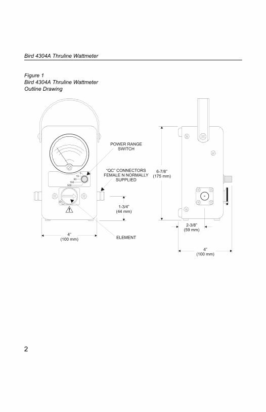
The Bird 4304A Wattmeter is an in-line sensor that measures RF power and load match in 50Ω coaxial transmission lines. It can be used with CW, AM, FM, and TV modulation, but not pulse modulation. It is supplied with a special broadband element with a frequency range of 25 to 1000 MHz. It can measure up to 500 W, depending on the frequency, and has a maximum VSWR of 1.07 with the standard “N” connectors. A range switch allows the full scale power to be reduced for greater accuracy.
The wattmeter is portable, with an included carrying strap. It has an aluminum housing and an easily removed back cover, with bumpers on the base and back that allow the meter to stand or lie flat. For additional protection, the microammeter is specially shock mounted. A screw on the lower front face of the meter is used to zero the pointer. Below the meter face, the RF line section protrudes slightly from the wattmeter housing with the element socket in the center.
The RF line section is precision machined to provide the best possible impedance match to the transmission line under test. A formed phosphor-bronze spring finger protrudes into the element socket to make contact with the element. At each end of the line section are Bird Quick-Change RF connectors that may be interchanged with any other Bird “QC” connector. The wattmeter housing does not interfere with connector changes.
Combining the Thruline Wattmeter with a Bird Termaline Load Resistor creates an accurate absorption wattmeter. With this combination, readings only need to be taken in the forward direction because the reflected power will be negligible.
1
Bird 4304A Thruline Wattmeter
Figure 1 Bird 4304A Thruline Wattmeter Outline Drawing
515
50150
500
6-7/8”(175 mm)
4”(100 mm)
2-3/8”(59 mm)
“QC” CONNECTORSFEMALE N NORMALLY
SUPPLIED
4”(100 mm)
1-3/4”(44 mm)
POWER RANGESWITCH
ELEMENT
2

Chapter 2 Theory of Operation
Travelling Wave Viewpoint
The easiest way to visualize Thruline operation is from a travelling wave viewpoint. In transmission lines the voltages, currents, standing waves, etc., on any uniform line section result from the interaction of two travelling waves:
The forward wave (and its power) travels from the source to the load. It has RF voltage Ef and current If in phase, with Ef / If = Zo.The reflected wave (and its power) originates by reflection at the load and travels from the load back to the source. It has an RF voltage Er and current Ir in phase, with Er / Ir = Zo.
Each wave is mathematically simple and has a constant power:
Wf = Watts Forward = Ef2 / Zo = If
2 Zo = Ef If
Wr = Watts Reflected = Er2 / Zo = Ir
2 Zo = Er Ir
Zo is the characteristic impedance of a uniform line section. For useful lines it is usually a pure resistance of 50Ω. The RF circuit of the Bird 43 is a length of uniform air line with Zo = 50Ω.
3
Bird 4304A Thruline Wattmeter
Coupling Circuit
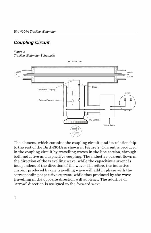
The element, which contains the coupling circuit, and its relationship to the rest of the Bird 4304A is shown in Figure 2. Current is produced in the coupling circuit by travelling waves in the line section, through both inductive and capacitive coupling. The inductive current flows in the direction of the travelling wave, while the capacitive current is independent of the direction of the wave. Therefore, the inductive current produced by one travelling wave will add in phase with the corresponding capacitive current, while that produced by the wave travelling in the opposite direction will subtract. The additive or “arrow” direction is assigned to the forward wave.
Figure 2 Thruline Wattmeter Schematic
RF Coaxial Line
XMTRorLOAD
LOADorXMTR
Directional Coupling
Detector Element
Diode
Meter
DC Contact
Circuit Board
4
Theory of Operation
The electrical characteristics of the element are carefully adjusted so that, for the reverse wave, the inductive current will completely cancel the capacitive current, giving a directivity greater than 20 dB. Thus, the element is sensitive at either of its settings, but to only one of the two travelling waves. Thruline Wattmeter measurements are also independent of position along the transmission line.
Like similar diode devices, the Bird 4304A indicates the carrier component of amplitude modulation, with very little response to side band components added by modulation.
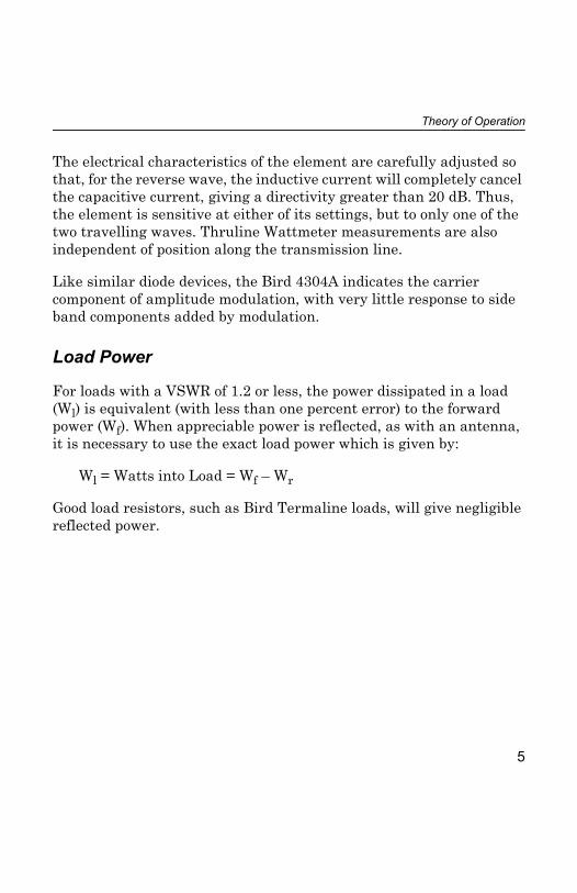
Load Power
For loads with a VSWR of 1.2 or less, the power dissipated in a load (Wl) is equivalent (with less than one percent error) to the forward power (Wf). When appreciable power is reflected, as with an antenna, it is necessary to use the exact load power which is given by:
Wl = Watts into Load = Wf – Wr
Good load resistors, such as Bird Termaline loads, will give negligible reflected power.
5
Bird 4304A Thruline Wattmeter
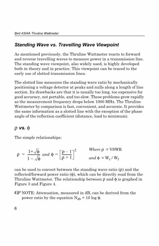
Standing Wave vs. Travelling Wave Viewpoint
As mentioned previously, the Thruline Wattmeter reacts to forward and reverse travelling waves to measure power in a transmission line. The standing wave viewpoint, also widely used, is highly developed both in theory and in practice. This viewpoint can be traced to the early use of slotted transmission lines.
The slotted line measures the standing wave ratio by mechanically positioning a voltage detector at peaks and nulls along a length of line section. Its drawbacks are that it is usually too long, too expensive for good accuracy, not portable, and too slow. These problems grow rapidly as the measurement frequency drops below 1000 MHz. The Thruline Wattmeter by comparison is fast, convenient, and accurate. It provides the same information as a slotted line with the exception of the phase angle of the reflection coefficient (distance, load to minimum).
ρ vs. φ
The simple relationships:
can be used to convert between the standing wave ratio (ρ) and the reflected/forward power ratio (φ), which can be directly read from the Thruline Wattmeter. The relationship between ρ and φ is graphed in Figure 3 and Figure 4.
NOTE: Attenuation, measured in dB, can be derived from the power ratio by the equation Ndb = 10 log φ.
and Where ρ = VSWR
and φ = Wr / Wfρ 1+ φ
1 φ–----------------= φ ρ 1–
ρ 1+------------=2
6

Theory of Operation
VSWR scales and their attendant controls for setting the reference point have been intentionally omitted from the Bird 4304A. Experience using the Thruline Wattmeter for transmitter tune-up, antenna matching, etc. will show that the power ratio measurement is as useful in practice as the standing wave ratio.
A trial is suggested – forget about VSWR for a few days and think in terms of φ = Wr / Wf. The two meter readings, Wr and Wf, give a useful, approximate picture of the results without bothering to calculate the power ratio exactly. Consider that, for an antenna matching problem, the main objective usually is to minimize Wr. Anything done experimentally to this end will be seen when the element is turned to the reflected power position.
7

Bird 4304A Thruline Wattmeter
Figure 3 Percent Reflected Power vs. VSWR (1.0 – 1.3)
8

Theory of Operation
Figure 4 Percent Reflected Power vs. VSWR (1.0 – 8.0)
9
Bird 4304A Thruline Wattmeter
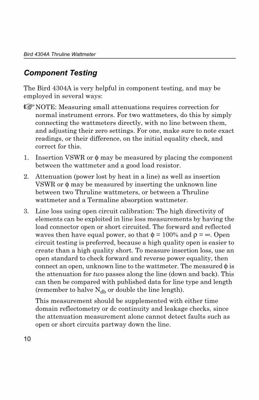
Component Testing
The Bird 4304A is very helpful in component testing, and may be employed in several ways: NOTE: Measuring small attenuations requires correction for
normal instrument errors. For two wattmeters, do this by simply connecting the wattmeters directly, with no line between them, and adjusting their zero settings. For one, make sure to note exact readings, or their difference, on the initial equality check, and correct for this.
1. Insertion VSWR or φ may be measured by placing the component between the wattmeter and a good load resistor.
2. Attenuation (power lost by heat in a line) as well as insertion VSWR or φ may be measured by inserting the unknown line between two Thruline wattmeters, or between a Thruline wattmeter and a Termaline absorption wattmeter.
3. Line loss using open circuit calibration: The high directivity of elements can be exploited in line loss measurements by having the load connector open or short circuited. The forward and reflected waves then have equal power, so that φ = 100% and ρ = ∞. Open circuit testing is preferred, because a high quality open is easier to create than a high quality short. To measure insertion loss, use an open standard to check forward and reverse power equality, then connect an open, unknown line to the wattmeter. The measured φ is the attenuation for two passes along the line (down and back). This can then be compared with published data for line type and length (remember to halve Ndb or double the line length).This measurement should be supplemented with either time domain reflectometry or dc continuity and leakage checks, since the attenuation measurement alone cannot detect faults such as open or short circuits partway down the line.
10

Theory of Operation
Impedance Mismatch
In some cases it may be necessary to use the Bird 4304A with a non-50Ω transmission line. If the reflected power is less than 10% and the frequency is below 200 MHz, the resulting mismatch will not be too serious. At higher frequencies or reflected power levels, the load impedance will change when the wattmeter is removed.
When the line and load impedances are known, the system’s VSWR equals the ratio of the two. Always divide the larger impedance by the smaller, since VSWR must be greater than 1.
As an example, consider using a Bird 4304A to tune a 70Ω line. If the load impedance is also 70Ω, the wattmeter will measure a VSWR of 70/50 = 1.4. However, if you remove the wattmeter, the VSWR will actually be 1.0. Similarly, if the load impedance is 35.7Ω, the VSWR will be 50/35.7 = 1.4 with the wattmeter and 70/35.7 = 2.0 without it. Caution must therefore be used, since both good and bad matches can have the same measured VSWR. In this case, the correct impedance can be determined by slightly changing the load impedance. When the load impedance is near 70Ω, the Bird 43 will read increasing VSWR as the load impedance is increased.
NOTE: When working with non-50Ω lines, it is especially important to calculate the exact load power by subtracting the reflected power from the forward power.
11

Bird 4304A Thruline Wattmeter
12
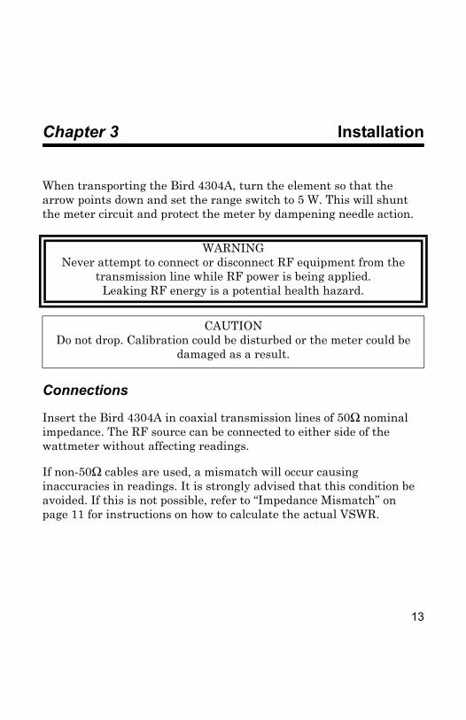
Chapter 3 Installation
When transporting the Bird 4304A, turn the element so that the arrow points down and set the range switch to 5 W. This will shunt the meter circuit and protect the meter by dampening needle action.
Connections
Insert the Bird 4304A in coaxial transmission lines of 50Ω nominal impedance. The RF source can be connected to either side of the wattmeter without affecting readings.
If non-50Ω cables are used, a mismatch will occur causing inaccuracies in readings. It is strongly advised that this condition be avoided. If this is not possible, refer to “Impedance Mismatch” on page 11 for instructions on how to calculate the actual VSWR.
WARNINGNever attempt to connect or disconnect RF equipment from the
transmission line while RF power is being applied.Leaking RF energy is a potential health hazard.
CAUTIONDo not drop. Calibration could be disturbed or the meter could be
damaged as a result.
13
Bird 4304A Thruline Wattmeter
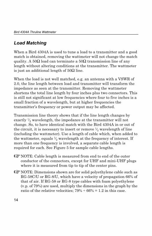
Load Matching
When a Bird 4304A is used to tune a load to a transmitter and a good match is obtained, removing the wattmeter will not change the match quality. A 50Ω load can terminate a 50Ω transmission line of any length without altering conditions at the transmitter. The wattmeter is just an additional length of 50Ω line.
When the load is not well matched, e.g. an antenna with a VSWR of 2.0, the line length between load and transmitter will transform the impedance as seen at the transmitter. Removing the wattmeter shortens the total line length by four inches plus two connectors. This is still not significant at low frequencies where four to five inches is a small fraction of a wavelength, but at higher frequencies the transmitter’s frequency or power output may be affected.
Transmission line theory shows that if the line length changes by exactly 1⁄2 wavelength, the impedance at the transmitter will not change. So, to have identical match with the Bird 4304A in or out of the circuit, it is necessary to insert or remove 1⁄2 wavelength of line (including the wattmeter). Use a length of cable which, when added to the wattmeter, equals 1⁄2 wavelength at the frequency of interest. If more than one frequency is involved, a separate cable length is required for each. See Figure 5 for sample cable lengths.
NOTE: Cable length is measured from end to end of the outer conductor of the connectors, except for UHF and mini-UHF plugs where it is measured from tip to tip of the center pins.
NOTE: Dimensions shown are for solid polyethylene cable such as RG-58C/U or RG-8/U, which have a velocity of propagation 66% of that of air. If RG-58 or RG-8 type cables with foam polyethylene (v.p. of 79%) are used, multiply the dimensions in the graph by the ratio of the relative velocities; 79% ÷ 66% = 1.2 in this case.
14

Installation
Figure 5 Cable Length / Wavelength Matching
15
Bird 4304A Thruline Wattmeter
16

Chapter 4 Operating Instructions
Normal Operation
Turn the element so that the arrow points towards the load to measure forward power. Turn it so that the arrow points towards the source to measure reflected power.Set the range switch to 500 W.Turn on the RF source.Read the power using the scale with 500 W full-scale.
NOTE: For greater accuracy, after estimating the power with 500W full-scale, set the range switch so the power is in the upper third of the scale.
WARNINGWhen working with RF powers of 200 watts or more, the potential of
the center conductor of the line section will exceed 100 volts.Do not touch the center conductor while RF power is on.
CAUTIONAbove 800 MHz, do not exceed 150 W RF power.
CAUTIONRF power must not exceed range switch setting.
17

Bird 4304A Thruline Wattmeter
Low Frequency
For frequencies below 100 MHz, a correction factor must be applied to the reading. The correction table is located on the back cover plate of the unit. Multiply the measured power by the correction factor to determine the actual power.
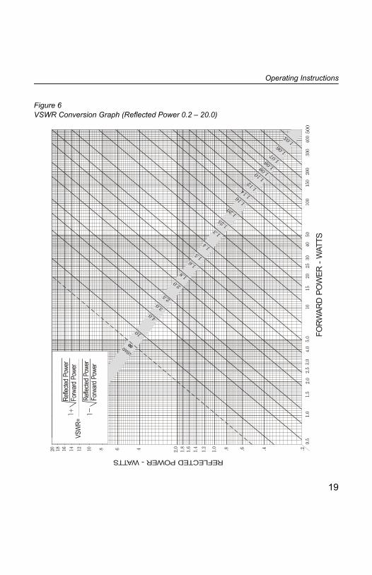
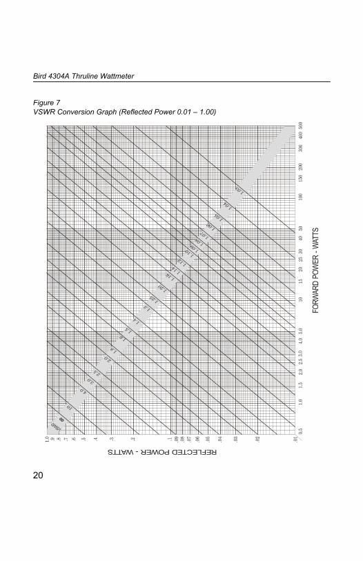
VSWR Measurements
For your convenience, a set of VSWR conversion nomographs is provided on pages 19 and 20. With these charts, VSWR may be determined from the forward and reflected power readings. Find the intersection of the forward and reflected power measurements. The slanted line passing closest to this point indicates the VSWR.
18
Operating Instructions
Figure 6 VSWR Conversion Graph (Reflected Power 0.2 – 20.0)
19
Bird 4304A Thruline Wattmeter
Figure 7 VSWR Conversion Graph (Reflected Power 0.01 – 1.00)
20
Chapter 5 Maintenance
The rugged and simple design of the Bird 4304A means that it requires minimal routine maintenance.
Cleaning
It is important to keep the following surfaces clean:
Socket boreDC contacts on the elementTeflon insulators
If any of the contacts or line connectors are dirty, clean them with a cotton swab dipped in commercial contact cleaner or isopropyl alcohol.
WARNINGNever attempt to connect or disconnect RF equipment from the
transmission line while RF power is being applied.Leaking RF energy is a potential health hazard.
CAUTIONDo not drop. Calibration could be disturbed or the meter could be
damaged as a result.
CAUTIONDo not attempt to remove the RF center conductor.
This will damage the line section.
21
Bird 4304A Thruline Wattmeter
If the RF line section seems dirty, do not loosen any connections. Clean accessible components as described above and use dry, clean air to blow out the interior.
The outside of the meter housing can be cleaned with a soft cloth dampened with a mild detergent solution. Do not wipe the meter glass with a dry cloth, or a static charge could develop that would cause an erroneous meter indication.
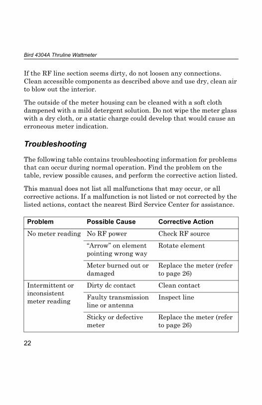
Troubleshooting
The following table contains troubleshooting information for problems that can occur during normal operation. Find the problem on the table, review possible causes, and perform the corrective action listed.
This manual does not list all malfunctions that may occur, or all corrective actions. If a malfunction is not listed or not corrected by the listed actions, contact the nearest Bird Service Center for assistance.
Problem Possible Cause Corrective Action
No meter reading No RF power Check RF source
“Arrow” on element pointing wrong way
Rotate element
Meter burned out or damaged
Replace the meter (refer to page 26)
Intermittent or inconsistent meter reading
Dirty dc contact Clean contact
Faulty transmission line or antenna
Inspect line
Sticky or defective meter
Replace the meter (refer to page 26)
22
Maintenance
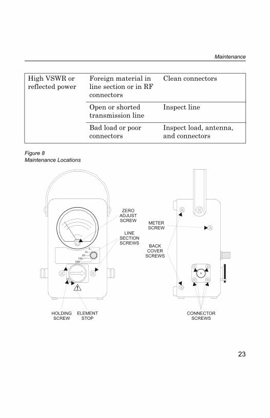
High VSWR or reflected power
Foreign material in line section or in RF connectors
Clean connectors
Open or shorted transmission line
Inspect line
Bad load or poor connectors
Inspect load, antenna, and connectors
Figure 8 Maintenance Locations
515
50150
500
ZEROADJUSTSCREW METER
SCREW
CONNECTORSCREWS
ELEMENTSTOP
HOLDINGSCREW
LINESECTIONSCREWS BACK
COVERSCREWS
23
Bird 4304A Thruline Wattmeter
Zero Adjust
The meter’s zero setting should be checked when no RF power is present. When no power is applied the pointer should rest exactly on zero. If adjustment is required, turn the adjustment screw until the pointer is set at zero (see Figure 8 on page 23).
Connector Replacement
The Bird 4304A has Bird “QC” connectors which are designed to be easily changed. To change the connector, remove the four screws at its corners and then pull it straight out. Push the new connector in, making sure that the center pin on the connector aligns with the socket, and screw into place.
Element Removal
NOTE: If the element is replaced, the unit will need to be returned to a Bird Service Center for recalibration. Changing elements without recalibrating will result in inaccurate readings.
1. Remove the screw at the lower left corner of the element socket.2. Move the stop over the hole where the screw had been until it is
free from the element.3. Pull the element out while turning slightly clockwise.4. To replace the element, reverse these steps. Make sure that the
stop is on the element before replacing the screw.
WARNINGNever attempt to connect or disconnect RF equipment from the
transmission line while RF power is being applied.Leaking RF energy is a potential health hazard.
24
Maintenance
Back Cover Removal
Before replacing the line section or meter, the back cover must be removed as follows (see Figure 8 on page 23):
1. Remove the screws on the rear of either side of the housing.2. Pull the back cover straight off.
Line Section Replacement
1. Remove the element (See “Element Removal” on page 24).2. Use a 5⁄16" hex wrench to loosen the nuts on the meter terminals.
Remove the wires from the terminals.3. Use a 5⁄16" allen wrench to loosen the set screws on the range
switch knob. Remove the knob.4. While supporting the line section, remove the screws on the front
of the housing, located on either side of the element socket. Pull the line section and attached circuit board out the back.
5. Remove both screws securing the circuit board to the line section and remove the circuit board.
6. Replace the line section and reassemble by reversing these steps. NOTE: The circuit board cannot be replaced in the field. If the
circuit board is defective, return the unit to a Bird Service Center.
CAUTIONWhen handling the circuit board, use caution:
Do not bend the dc contact finger that extends into the line section.Do not lose the contact finger insulator or the
spacers on the mounting screws.Do not disturb the potentiometer settings.
25
Bird 4304A Thruline Wattmeter
Meter Replacement
1. Use a 5⁄16" hex wrench to loosen the nuts on the meter terminals. Remove the wires from the terminals.
2. Remove both screws on the sides of the housing, to either side of the meter.
3. Remove the meter assembly.4. Make sure that the shock ring, gasket, and mounting bracket are
in place on the new meter. The shock ring should be on the front face of the meter, and the mounting ring and mounting bracket on the back. Align the bracket so that the mounting holes are parallel to the meter lugs.
5. Place the housing face-down on a flat surface.6. Insert the meter assembly, pressing until the side holes line up
with the holes in the housing. Screw into place.
Calibration Checks
This test determines if the wattmeter needs recalibration:
1. The following equipment is required, connected in series with the Bird 4304A (Refer to Figure 9).
RF sourceLow pass filterReference, known accurate, wattmeter50Ω loadCables
26

Maintenance
NOTE: Keep all connections as short as possible to minimize mismatch and insertion losses.
2. For each power range, set the RF source to produce a signal with power in the upper one-third of the scale.
3. Compare the reading on the Bird 4304A with the reference wattmeter.
4. If the unit is outside the stated accuracy range, return it to a Bird Service Center for calibration.
Figure 9 Calibration Check Setup
515
50150
500
Low PassFilter
4304ARF Source 50 LoadΩReferenceWattmeter
27
Bird 4304A Thruline Wattmeter
Storage
When storing the Bird 4304A, turn the element so that the arrow points down and set the range switch to 5 W. This will shunt the meter circuit and protect the meter by dampening needle action.
Customer Service
Any maintenance or service procedure beyond the scope of those in this chapter should be referred to a qualified service center.
If you need to return the unit for any reason, contact the Bird Service Center for a return authorization. All instruments returned must be shipped prepaid and to the attention of Bird Service Center.
Bird Service Center 30303 Aurora Road Cleveland (Solon), OH 44139-2794 Phone: (440) 519-2298 Fax: (440) 519-2326 E-Mail: [email protected]
For the location of the Sales Office nearest you, give us a call or visit our Web site at:
http://www.bird-electronic.com
28

Maintenance
Specifications
Frequency Range 25 – 1000 MHz
Power Rating 500 W, 25 – 800 MHz 150 W, 800 – 1000 MHz
Power Range Settings 5 / 15 / 50 / 150 / 500 W
Insertion VSWR (Max.)
UHF Connnector
N Connector
1.08, 25 – 512 MHz 1.12, 512 – 1000 MHz 1.05, 25 – 512 MHz 1.07, 512 – 1000 MHz
Insertion Loss (Max.)
UHF Connnector
N Connector
0.1 dB, 25 – 512 MHz 0.15 dB, 512 – 1000 MHz 0.1 dB, 25 – 512 MHz 0.13 dB, 512 – 1000 MHz
Accuracy
25 – 100 MHz
100 – 512 MHz 512 – 1000 MHz
± 7% of full scale (with correction factor) ± 6% of full scale ± 7% of full scale
Impedance, Nominal 50Ω
Connectors Bird “QC”, Female, N or UHF, normally supplied
29
Bird 4304A Thruline Wattmeter
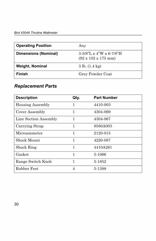
Replacement Parts
Operating Position Any
Dimensions (Nominal) 3-5/8”L x 4”W x 6-7/8”H (92 x 102 x 175 mm)
Weight, Nominal 3 lb. (1.4 kg)
Finish Grey Powder Coat
Description Qty. Part Number
Housing Assembly 1 4410-003
Cover Assembly 1 4304-069
Line Section Assembly 1 4304-067
Carrying Strap 1 8580A003
Microammeter 1 2120-015
Shock Mount 1 4220-087
Shock Ring 1 4410A261
Gasket 1 5-1066
Range Switch Knob 1 5-1852
Rubber Feet 4 5-1388
30

Maintenance
Available “QC” Type Connectors
Connector Part Number Connector Part Number
BNC-Female 4240-125 LT-Female 4240-018
BNC-Male 4240-132 LT-Male 4240-012
C-Female 4240-100 N-Female 4240-062
C-Male 4240-110 N-Male 4240-063
HN-Female 4240-268 SMA-Female 4240-336
HN-Male 4240-278 SMA-Male 4240-334
LC-Female 4240-031 7/16 Jack, IEC Type 169-4
4240-344
LC-Male 4240-025 7/16 Plug, IEC Type 169-4
4240-363
UHF-Female 4240-050 TNC-Female 4240-156
UHF-Male 4240-179 TNC-Male 4240-160
Mini UHF-Female
4240-346 1-5/8” EIA Swivel
4240-208
SC-Female 4240-090 1-5/8” EIA Fixed 4240-096
Open Term. # 10-32 Nut
4240-080 7/8” EIA 4240-002
31
Limited Warranty
All products manufactured by Seller are warranted to be free from defects in material and workmanship for a period of one (1) year, unless otherwise speci-fied, from date of shipment and to conform to applicable specifications, draw-ings, blueprints and/or samples. Seller’s sole obligation under these warranties shall be to issue credit, repair or replace any item or part thereof which is proved to be other than as warranted; no allowance shall be made for any labor charges of Buyer for replacement of parts, adjustment or repairs, or any other work, unless such charges are authorized in advance by Seller.If Seller’s products are claimed to be defective in material or workmanship or not to conform to specifications, drawings, blueprints and/or samples, Seller shall, upon prompt notice thereof, either examine the products where they are located or issue shipping instructions for return to Seller (transportation-charges prepaid by Buyer). In the event any of our products are proved to be other than as warranted, transportation costs (cheapest way) to and from Seller’s plant, will be borne by Seller and reimbursement or credit will be made for amounts so expended by Buyer. Every such claim for breach of these warranties shall be deemed to be waived by Buyer unless made in writing within ten (10) days from the date of discovery of the defect.The above warranties shall not extend to any products or parts thereof which have been subjected to any misuse or neglect, damaged by accident, rendered defective by reason of improper installation or by the performance of repairs or alterations outside of our plant, and shall not apply to any goods or parts thereof furnished by Buyer or acquired from others at Buyer’s request and/or to Buyer’s specifications. Routine (regularly required) calibration is not cov-ered under this limited warranty. In addition, Seller’s warranties do not extend to the failure of tubes, transistors, fuses and batteries, or to other equipment and parts manufactured by others except to the extent of the origi-nal manufacturer’s warranty to Seller.The obligations under the foregoing warranties are limited to the precise terms thereof. These warranties provide exclusive remedies, expressly in lieu of all other remedies including claims for special or consequential damages. SELLER NEITHER MAKES NOR ASSUMES ANY OTHER WARRANTY WHATSOEVER, WHETHER EXPRESS, STATUTORY, OR IMPLIED, INCLUDING WARRANTIES OF MERCHANTABILITY AND FITNESS, AND NO PERSON IS AUTHORIZED TO ASSUME FOR SELLER ANY OBLIGATION OR LIABILITY NOT STRICTLY IN ACCORDANCE WITH THE FOREGOING.