blackfin cm-bf537e hardware user manualdownload.ronetix.info/boards/doc/bf5xx/cm-bf537/cm... ·...
TRANSCRIPT

www.tinyboards.com
Maximum Power at Minimum Size
Hardware User Manual
CM-BF537E V1.1 (V1.2)
Bluetechnix www.tinyboards.com Maximum Power at Minimum Size
Blackfin CM-BF537E Hardware User Manual
Contact
Bluetechnix Mechatronische Systeme GmbH
Waidhausenstr. 3/19
A-1140 Vienna
AUSTRIA/EUROPE
http://www.bluetechnix.com
Document No.: 100-1221-1.1
Version 7
Date: 2007-05-03

Bluetechnix www.tinyboards.com Maximum Power at Minimum Size
Blackfin CM-BF537E Hardware User Manual
Table of Contents
1 Introduction ......................................................................................................................... 1
1.1 Overview ....................................................................................................................... 1
1.2 Benefits ......................................................................................................................... 2
1.3 Applications .................................................................................................................. 2
2 Specification ........................................................................................................................ 3
2.1 Functional Specification ............................................................................................... 3
2.2 Boot Mode .................................................................................................................... 3
2.3 Memory MAP ............................................................................................................... 4
2.4 Electrical Specification ................................................................................................. 4
2.4.1 Supply Voltage ....................................................................................................... 4
2.4.2 Supply Voltage Ripple ........................................................................................... 4
2.4.3 External Oscillator Frequency ................................................................................ 4
2.4.4 Real Time Clock Crystal ........................................................................................ 4
2.4.5 Supply Current ....................................................................................................... 4
2.5 Environmental Specification ......................................................................................... 4
2.5.1 Temperature............................................................................................................ 4
2.5.2 Humidity ................................................................................................................. 5
3 CM-BF537E (Connector Version) ...................................................................................... 6
3.1 Mechanical Outline ....................................................................................................... 6
3.2 Footprint - Connector Version ...................................................................................... 7
3.3 Top Mounted Components ........................................................................................... 8
3.4 Schematic Symbol (Signals of P1 and P2) .................................................................... 9
3.5 Connectors Pin Assignment ........................................................................................ 10
3.5.1 Connector P1 – (1-60) .......................................................................................... 10
3.5.2 Connector P2 – (61-120) ...................................................................................... 11
3.5.3 Pin out Description ............................................................................................... 12
3.6 RJ45 schematic ........................................................................................................... 12
4 Test Points ......................................................................................................................... 14
4.1 Footprint – Test Points ................................................................................................ 14
5 Software Support ............................................................................................................... 15
5.1 BLACKSheep ............................................................................................................. 15
5.2 uClinux ........................................................................................................................ 15
6 Application Examples ....................................................................................................... 16
Bluetechnix www.tinyboards.com Maximum Power at Minimum Size
Blackfin CM-BF537E Hardware User Manual
6.1 Sample Schematic ....................................................................................................... 16
6.2 Stand-alone Ethernet based MPEG Webcam .............................................................. 17
6.3 Design Services ........................................................................................................... 18
7 Known Bugs ...................................................................................................................... 19
8 Product Changes ................................................................................................................ 20
9 Document Revision History .............................................................................................. 21
A List of Figures and Tables ................................................................................................. 22

Bluetechnix www.tinyboards.com Maximum Power at Minimum Size
Blackfin CM-BF537E Hardware User Manual
Edition 2007-02
© Bluetechnix Mechatronische Systeme GmbH 2007
All Rights Reserved.
The information herein is given to describe certain components and shall not be considered as
a guarantee of characteristics.
Terms of delivery and rights of technical change reserved.
We hereby disclaim any warranties, including but not limited to warranties of non-
infringement, regarding circuits, descriptions and charts stated herein.
Bluetechnix makes and you receive no warranties or conditions, express, implied, statutory or
in any communication with you. Bluetechnix specifically disclaims any implied warranty of
merchantability or fitness for a particular purpose.
Bluetechnix takes no liability for any damages and errors causing of the usage of this board.
The user of this board is responsible by himself for the functionality of his application. He is
allowed to use the board only if he has the qualification. More information is found in the
General Terms and Conditions (AGB).
Information
For further information on technology, delivery terms and conditions and prices please contact
Bluetechnix (http://www.bluetechnix.com).
Warnings
Due to technical requirements components may contain dangerous substances.
The Core Boards and Development
systems contain ESD (electrostatic
discharge) sensitive devices. Electro-
static charges readily accumulate on
the human body and equipment and
can discharge without detection.
Permanent damage may occur on
devices subjected to high-energy
discharges. Proper ESD precautions
are recommended to avoid
performance degradation or loss of
functionality. Unused core boards and
development boards should be stored
in the protective shipping package.
Bluetechnix www.tinyboards.com Maximum Power at Minimum Size
Blackfin CM-BF537E Hardware User Manual
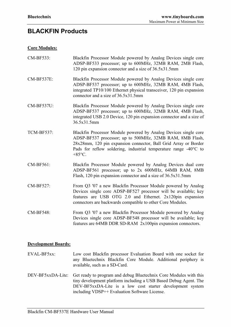
BLACKFIN Products
Core Modules:
CM-BF533: Blackfin Processor Module powered by Analog Devices single core
ADSP-BF533 processor; up to 600MHz, 32MB RAM, 2MB Flash,
120 pin expansion connector and a size of 36.5x31.5mm
CM-BF537E: Blackfin Processor Module powered by Analog Devices single core
ADSP-BF537 processor; up to 600MHz, 32MB RAM, 4MB Flash,
integrated TP10/100 Ethernet physical transceiver, 120 pin expansion
connector and a size of 36.5x31.5mm
CM-BF537U: Blackfin Processor Module powered by Analog Devices single core
ADSP-BF537 processor; up to 600MHz, 32MB RAM, 4MB Flash,
integrated USB 2.0 Device, 120 pin expansion connector and a size of
36.5x31.5mm
TCM-BF537: Blackfin Processor Module powered by Analog Devices single core
ADSP-BF537 processor; up to 500MHz, 32MB RAM, 8MB Flash,
28x28mm, 120 pin expansion connector, Ball Grid Array or Border
Pads for reflow soldering, industrial temperature range -40°C to
+85°C.
CM-BF561: Blackfin Processor Module powered by Analog Devices dual core
ADSP-BF561 processor; up to 2x 600MHz, 64MB RAM, 8MB
Flash, 120 pin expansion connector and a size of 36.5x31.5mm
CM-BF527: From Q3 '07 a new Blackfin Processor Module powered by Analog
Devices single core ADSP-BF527 processor will be available; key
features are USB OTG 2.0 and Ethernet. 2x120pin expansion
connectors are backwards compatible to other Core Modules.
CM-BF548: From Q3 '07 a new Blackfin Processor Module powered by Analog
Devices single core ADSP-BF548 processor will be available; key
features are 64MB DDR SD-RAM 2x100pin expansion connectors.
Development Boards:
EVAL-BF5xx: Low cost Blackfin processor Evaluation Board with one socket for
any Bluetechnix Blackfin Core Module. Additional periphery is
available, such as a SD-Card.
DEV-BF5xxDA-Lite: Get ready to program and debug Bluetechnix Core Modules with this
tiny development platform including a USB Based Debug Agent. The
DEV-BF5xxDA-Lite is a low cost starter development system
including VDSP++ Evaluation Software License.
Bluetechnix www.tinyboards.com Maximum Power at Minimum Size
Blackfin CM-BF537E Hardware User Manual
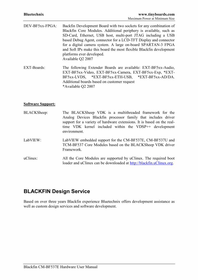
DEV-BF5xx-FPGA: Backfin Development Board with two sockets for any combination of
Blackfin Core Modules. Additional periphery is available, such as
SD-Card, Ethernet, USB host, multi-port JTAG including a USB
based Debug Agent, connector for a LCD-TFT Display and connector
for a digital camera system. A large on-board SPARTAN-3 FPGA
and Soft IPs make this board the most flexible Blackfin development
platforms ever developed.
Available Q2 2007
EXT-Boards: The following Extender Boards are available: EXT-BF5xx-Audio,
EXT-BF5xx-Video, EXT-BF5xx-Camera, EXT-BF5xx-Exp, *EXT-
BF5xx-LVDS, *EXT-BF5xx-ETH-USB, *EXT-BF5xx-AD/DA.
Additional boards based on customer request
*Available Q2 2007
Software Support:
BLACKSheep: The BLACKSheep VDK is a multithreaded framework for the
Analog Devices Blackfin processor family that includes driver
support for a variety of hardware extensions. It is based on the real-
time VDK kernel included within the VDSP++ development
environment.
LabVIEW: LabVIEW embedded support for the CM-BF537E, CM-BF537U and
TCM-BF537 Core Modules based on the BLACKSheep VDK driver
Framework.
uClinux: All the Core Modules are supported by uClinux. The required boot
loader and uClinux can be downloaded at http://blackfin.uClinux.org.
BLACKFIN Design Service
Based on over three years Blackfin experience Bluetechnix offers development assistance as
well as custom design services and software development.

Bluetechnix www.tinyboards.com Maximum Power at Minimum Size
Blackfin CM-BF537E Hardware User Manual Page 1
1 Introduction
The CM-BF537E is a tiny, high performance and low power DSP/RISC Core Module
incorporating Analog Devices Blackfin family of processors. The special feature of this
module is the on-board 10/100Mbit Ethernet interface which includes the physical transceiver
chip. The module allows easy integration into high demanding very space and power limited
applications.
1.1 Overview
The Core Module CM-BF537E consists of the following components:
32 MByte
SDRam
60 Pin Expansion Connector A
4 MByte
FlashBF537
up to
600 MHz
Dynamic
Core Voltage
Control
60 Pin Expansion Connector B
Low Voltage
Reset
Ethernet
Physical
Figure 1-1: Main components of the CM-BF537E Core Module
Analog Devices Blackfin Processor BF537
o Supported Chips :
ADSP-BF537SBBC1500 (-40°-85°C) Option upon request
ADSP-BF537SKBC1600 (0°-70°C) Standard Mount
32 MB SDRAM
o SDRAM Clock up to 133MHz
o MT48LC16M16A2BG-7 (16Mx16, 256Mbit at 3.3 V)
4 MB of Addressable Flash
o ITLRC28F320J3C110 (2Mx16 32Mbit at 3.3 V; all 4 MByte addressable)
o Additional flash memory can be connected through the expansion board as
parallel flash using asynchronous chip select lines or as a SPI flash.
Bluetechnix www.tinyboards.com Maximum Power at Minimum Size
Blackfin CM-BF537E Hardware User Manual Page 2
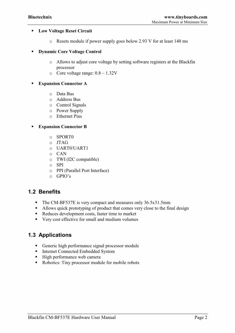
Low Voltage Reset Circuit
o Resets module if power supply goes below 2.93 V for at least 140 ms
Dynamic Core Voltage Control
o Allows to adjust core voltage by setting software registers at the Blackfin
processor
o Core voltage range: 0.8 – 1.32V
Expansion Connector A
o Data Bus
o Address Bus
o Control Signals
o Power Supply
o Ethernet Pins
Expansion Connector B
o SPORT0
o JTAG
o UART0/UART1
o CAN
o TWI (I2C compatible)
o SPI
o PPI (Parallel Port Interface)
o GPIO’s
1.2 Benefits
The CM-BF537E is very compact and measures only 36.5x31.5mm
Allows quick prototyping of product that comes very close to the final design
Reduces development costs, faster time to market
Very cost effective for small and medium volumes
1.3 Applications
Generic high performance signal processor module
Internet Connected Embedded System
High performance web camera
Robotics: Tiny processor module for mobile robots
Bluetechnix www.tinyboards.com Maximum Power at Minimum Size
Blackfin CM-BF537E Hardware User Manual Page 3
2 Specification
2.1 Functional Specification
32 MByte
SDRam
4 MByte
Flash
BF537
up to
600MHz
Dynamic
Core Voltage
Control
Low Voltage
Reset
20 Bit Address Bus
16 Bit Data BusEthernet
Physical
Clock
Mem. Control, Boot Mode, JTAG, Ethernet
Data
& A
ddre
ss B
us
Clock-out PPI, SPORT0, UART1, UART2, SPI, TWI, CAN, GPIO
3V
3 P
ow
er
, R
eset
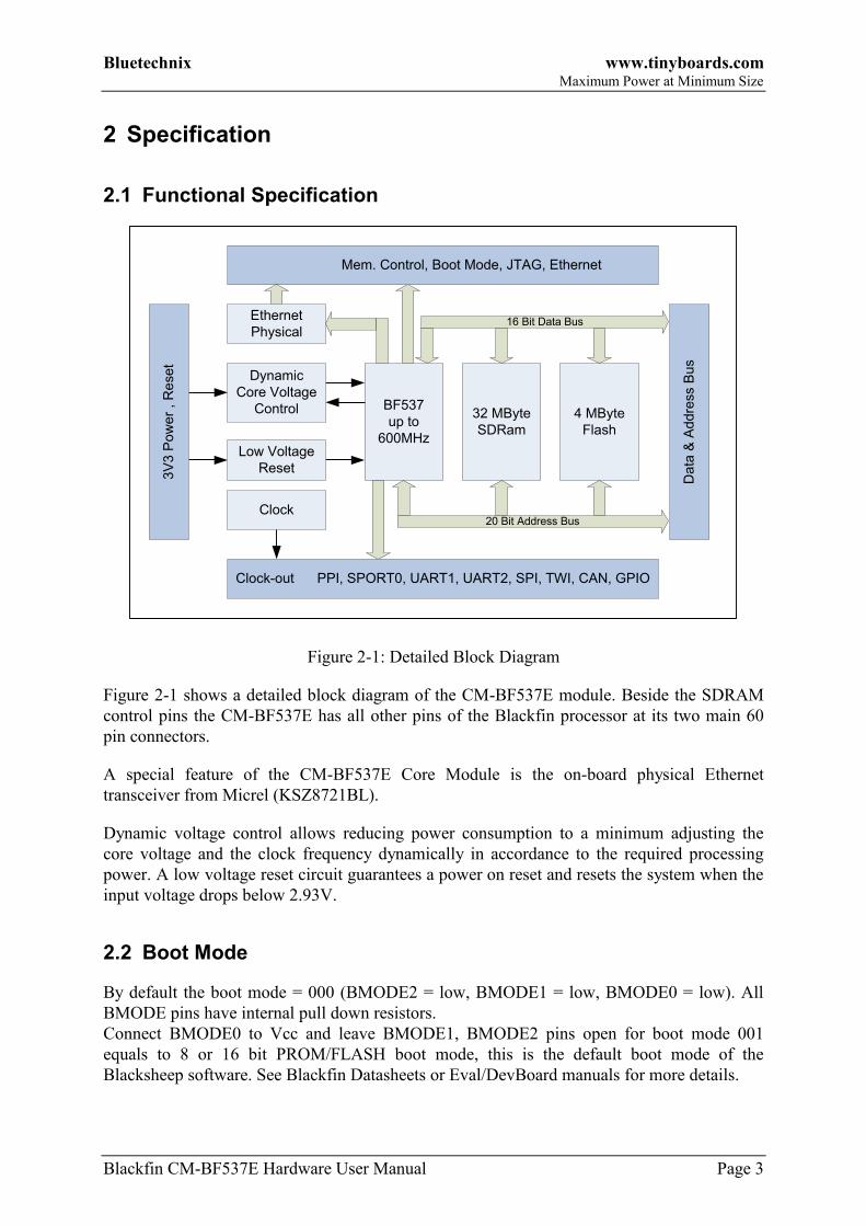
Figure 2-1: Detailed Block Diagram
Figure 2-1 shows a detailed block diagram of the CM-BF537E module. Beside the SDRAM
control pins the CM-BF537E has all other pins of the Blackfin processor at its two main 60
pin connectors.
A special feature of the CM-BF537E Core Module is the on-board physical Ethernet
transceiver from Micrel (KSZ8721BL).
Dynamic voltage control allows reducing power consumption to a minimum adjusting the
core voltage and the clock frequency dynamically in accordance to the required processing
power. A low voltage reset circuit guarantees a power on reset and resets the system when the
input voltage drops below 2.93V.
2.2 Boot Mode
By default the boot mode = 000 (BMODE2 = low, BMODE1 = low, BMODE0 = low). All
BMODE pins have internal pull down resistors.
Connect BMODE0 to Vcc and leave BMODE1, BMODE2 pins open for boot mode 001
equals to 8 or 16 bit PROM/FLASH boot mode, this is the default boot mode of the
Blacksheep software. See Blackfin Datasheets or Eval/DevBoard manuals for more details.
Bluetechnix www.tinyboards.com Maximum Power at Minimum Size
Blackfin CM-BF537E Hardware User Manual Page 4
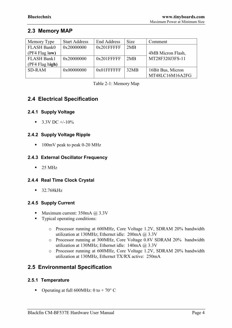
2.3 Memory MAP
Memory Type Start Address End Address Size Comment
FLASH Bank0
(PF4 Flag low)
0x20000000 0x201FFFFF 2MB
4MB Micron Flash,
MT28F320J3FS-11 FLASH Bank1
(PF4 Flag high)
0x20000000 0x201FFFFF 2MB
SD-RAM 0x00000000 0x01FFFFFF 32MB 16Bit Bus, Micron
MT48LC16M16A2FG
Table 2-1: Memory Map
2.4 Electrical Specification
2.4.1 Supply Voltage
3.3V DC +/-10%
2.4.2 Supply Voltage Ripple
100mV peak to peak 0-20 MHz
2.4.3 External Oscillator Frequency
25 MHz
2.4.4 Real Time Clock Crystal
32.768kHz
2.4.5 Supply Current
Maximum current: 350mA @ 3.3V
Typical operating conditions:
o Processor running at 600MHz, Core Voltage 1.2V, SDRAM 20% bandwidth
utilization at 130MHz; Ethernet idle: 200mA @ 3.3V
o Processor running at 300MHz, Core Voltage 0.8V SDRAM 20% bandwidth
utilization at 130MHz; Ethernet idle: 140mA @ 3.3V
o Processor running at 600MHz, Core Voltage 1.2V, SDRAM 20% bandwidth
utilization at 130MHz, Ethernet TX/RX active: 250mA
2.5 Environmental Specification
2.5.1 Temperature
Operating at full 600MHz: 0 to + 70° C

Bluetechnix www.tinyboards.com Maximum Power at Minimum Size
Blackfin CM-BF537E Hardware User Manual Page 5
2.5.2 Humidity
Operating: 10% to 90% (non condensing)
Bluetechnix www.tinyboards.com Maximum Power at Minimum Size
Blackfin CM-BF537E Hardware User Manual Page 6
3 CM-BF537E (Connector Version)
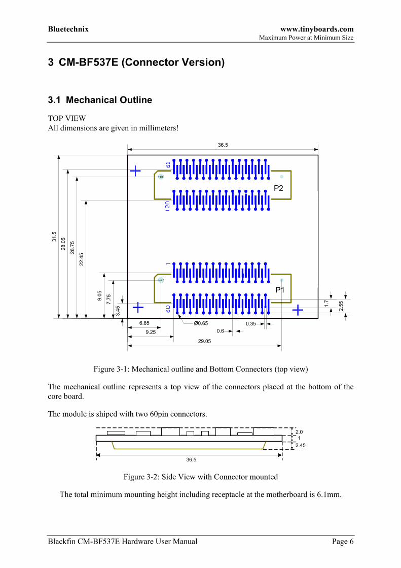
3.1 Mechanical Outline
TOP VIEW
All dimensions are given in millimeters!
P3
36.5
9.25
29.05
6.85
26
.75
28.0
531.5
22.4
5
0.6
0.35Ø0.65
2.5
5
1.77.7
5
9.0
5
3.4
5
P1
P2
Figure 3-1: Mechanical outline and Bottom Connectors (top view)
The mechanical outline represents a top view of the connectors placed at the bottom of the
core board.
The module is shiped with two 60pin connectors.
36.5
1
2.0
2.45
Figure 3-2: Side View with Connector mounted
The total minimum mounting height including receptacle at the motherboard is 6.1mm.

Bluetechnix www.tinyboards.com Maximum Power at Minimum Size
Blackfin CM-BF537E Hardware User Manual Page 7
3.2 Footprint - Connector Version
If the connector version (2x Hirose 0.6mm pitch) is used, the footprint for the baseboard may
look as shown in Figure 3-3.
For the baseboard the following connectors have to be used.
Part Baseboard Manufacturer Manufacturer Part No.
P1,P2 Hirose FX8-60S-SV
Table 3-1: Baseboard connector types
The Connectors on the CM-BF537E are of the following type:
Part Manufacturer Manufacturer Part No.
P1,P2 Hirose 3mm height FX8-60P-SV(21)
Table 3-2: Module connector types
36.5
26.7
531
.5
7.7
5
6.85
Figure 3-3: Connector footprint for the Core Module (top view)
Bluetechnix www.tinyboards.com Maximum Power at Minimum Size
Blackfin CM-BF537E Hardware User Manual Page 8
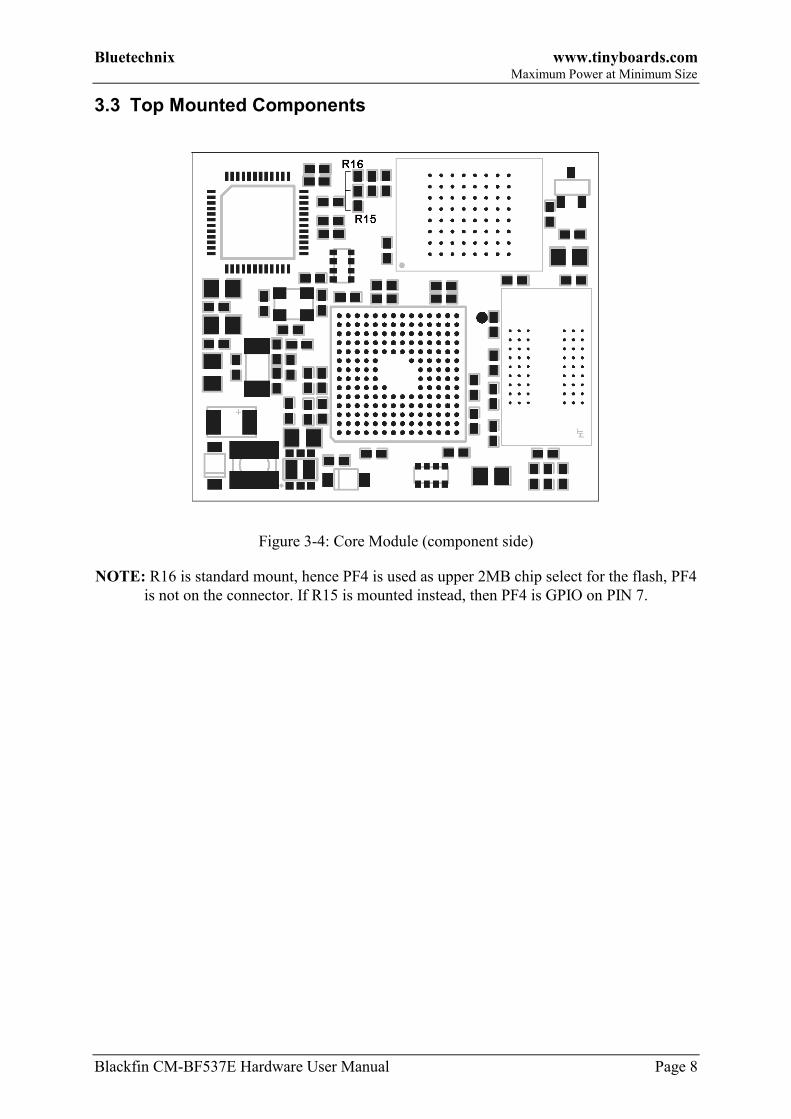
3.3 Top Mounted Components
Figure 3-4: Core Module (component side)
NOTE: R16 is standard mount, hence PF4 is used as upper 2MB chip select for the flash, PF4
is not on the connector. If R15 is mounted instead, then PF4 is GPIO on PIN 7.
Bluetechnix www.tinyboards.com Maximum Power at Minimum Size
Blackfin CM-BF537E Hardware User Manual Page 9
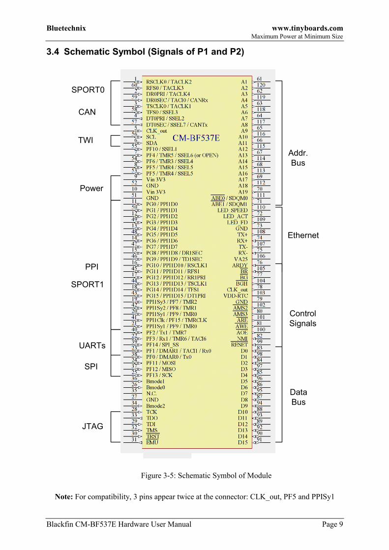
3.4 Schematic Symbol (Signals of P1 and P2)
SPORT0
PPI
UARTs
SPI
JTAG
Data
Bus
Addr.
Bus
Control
Signals
Ethernet
CAN
TWI
SPORT1
Power
Figure 3-5: Schematic Symbol of Module
Note: For compatibility, 3 pins appear twice at the connector: CLK_out, PF5 and PPISy1

Bluetechnix www.tinyboards.com Maximum Power at Minimum Size
Blackfin CM-BF537E Hardware User Manual Page 10
3.5 Connectors Pin Assignment
3.5.1 Connector P1 – (1-60)
Pin
No.
Signal Signal
type
Pin
No.
Signal Signal
type
1 RSCLK0/TACLK2 I/O 2 DR0PRI/ TACLK4 I
3 TSCLK0/TACLK1 I/O 4 DT0PRI/SSEL2 O
5 CLK_out O 6 SDA I/O
7 PF4/TMR5/SSEL6 * I/O 8 PF5/TMR4/SSEL5 I/O
9 Vin 3V3 PWR 10 Vin 3V3 PWR
11 PG0/PPI1D0 I/O 12 PG2/PPI1D2 I/O
13 PG4/PPI1D4 I/O 14 PG6/PPI1D6 I/O
15 PG8/PPI1D8/DR1SEC I/O 16 PG10/PPI1D10/RSCLK1 I/O
17 PG12/PPI1D12/RE1PRI I/O 18 PG14/PPI1D14/TFS1 I/O
19 PPI1SY3/PF7/TMR2 I/O 20 PPI1SY1/PF9/TMR0 I/O
21 PPI1SY1/PF9/TMR0 I/O 22 PF3/Rx1/TMR6/TACI6 I/O
23 PF1/DMAR1/TACI1/Rx0 I/O 24 PF11/MOSI I/O
25 PF13/SCK I/O 26 BMODE0 I
27 GND PWR 28 TCK I
29 TDI I 30 nTRST I
31 nEMU O 32 TMS I
33 TDO O 34 BMODE2 I
35 N.C. - 36 BMODE1 I
37 PF12/MISO I/O 38 PF0/DMAR0/Tx0 I/O
39 PF14/SPI_SS I/O 40 PF2/Tx1/TMR7 I/O
41 PPI1Clk/PF15/TMRCLK I/O 42 PPI1Sy2/PF8/TMR1 I/O
43 PG15/PPI1D15/DT1PRI I/O 44 PG13/PPI1D13/TSCLK1 I/O
45 PG11/PPI1D11/RFS1 I/O 46 PG9/PPI1D9/TD1SEC I/O
47 PG7/PPI1D7 I/O 48 PG5/PPI1D5 I/O
49 PG3/PPI1D3 I/O 50 PG1/PPI1D1 I/O
51 GND PWR 52 GND PWR
53 PF5/TMR4/SSEL5 I/O 54 PF6/TMR3/SSEL4 I/O
55 PF10/SSEL1 I/O 56 SCL I/O
57 DT0SEC/SSEL7/CANTx O 58 TFS0/SSEL3 I/O
59 DR0SEC/TACI0/
CANRx
I 60 RFS0/TACLK3 I/O
Table 3-3: Connector P1 pin assignment
* Pin 7 (PF4) is by default internally connected to the address A21 of the flash memory (for
addressing the upper 2MB of the 4MB Flash). If PF4 is needed and 2 MB flash are sufficient
move resistor R16 to the position of R15 as shown in Figure 3-4.
Bluetechnix www.tinyboards.com Maximum Power at Minimum Size
Blackfin CM-BF537E Hardware User Manual Page 11
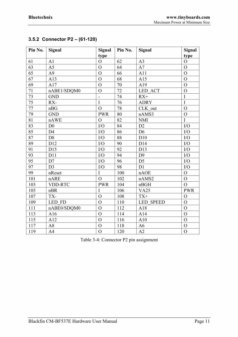
3.5.2 Connector P2 – (61-120)
Pin No. Signal Signal
type
Pin No. Signal Signal
type
61 A1 O 62 A3 O
63 A5 O 64 A7 O
65 A9 O 66 A11 O
67 A13 O 68 A15 O
69 A17 O 70 A19 O
71 nABE1/SDQM0 O 72 LED_ACT O
73 GND - 74 RX+ I
75 RX- I 76 ADRY I
77 nBG O 78 CLK_out O
79 GND PWR 80 nAMS3 O
81 nAWE O 82 NMI I
83 D0 I/O 84 D2 I/O
85 D4 I/O 86 D6 I/O
87 D8 I/O 88 D10 I/O
89 D12 I/O 90 D14 I/O
91 D15 I/O 92 D13 I/O
93 D11 I/O 94 D9 I/O
95 D7 I/O 96 D5 I/O
97 D3 I/O 98 D1 I/O
99 nReset I 100 nAOE O
101 nARE O 102 nAMS2 O
103 VDD-RTC PWR 104 nBGH O
105 nBR I 106 VA25 PWR
107 TX- O 108 TX+ O
109 LED_FD O 110 LED_SPEED O
111 nABE0/SDQM0 O 112 A18 O
113 A16 O 114 A14 O
115 A12 O 116 A10 O
117 A8 O 118 A6 O
119 A4 O 120 A2 O
Table 3-4: Connector P2 pin assignment
Bluetechnix www.tinyboards.com Maximum Power at Minimum Size
Blackfin CM-BF537E Hardware User Manual Page 12
3.5.3 Pin out Description
All pin names except those in Table 2-5 of the connectors are processor pins and correspond
closely to the names found in the Blackfin BF537 datasheet from Analog Devices.
PIN
Nr.
Name Description
5,78 CLK_out 25MHz buffered clock output
9,10 Vin 3.3V 3V3 +-10% 500mA peak for supply
35 nc Not connected
72 LED_ACT Indicates Ethernet activity
73 GND AGND (use as GND for Ethernet connector and Ethernet passives)
74 RX+ Ethernet receive +
75 RX- Ethernet receive -
106 VA25 Ethernet transformer voltage reference
107 TX- Ethernet transmit -
108 TX+ Ethernet transmit +
109 LED_FD Full duplex LED, High = Full duplex active, Low = inactive
110 LED_SPEED 10Mbps = Low, 100Mbps = High
Table 3-5: Pin description of all non Processor Pins on the CM-BF537E
All other pins are connected directly to the ADSP-BF537 processor.
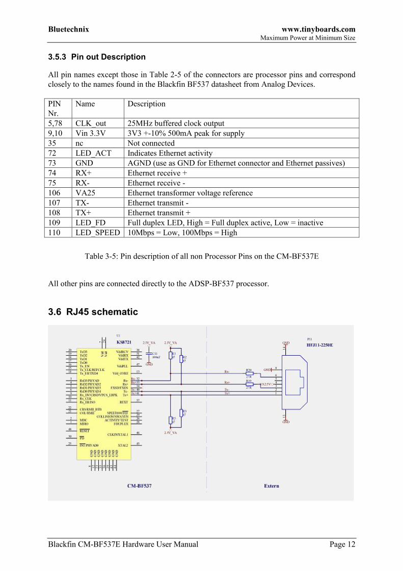
3.6 RJ45 schematic
Bluetechnix www.tinyboards.com Maximum Power at Minimum Size
Blackfin CM-BF537E Hardware User Manual Page 13
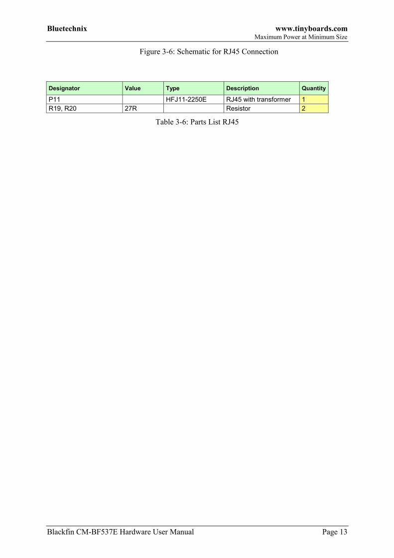
Figure 3-6: Schematic for RJ45 Connection
Designator Value Type Description Quantity
P11 HFJ11-2250E RJ45 with transformer 1
R19, R20 27R Resistor 2
Table 3-6: Parts List RJ45

Bluetechnix www.tinyboards.com Maximum Power at Minimum Size
Blackfin CM-BF537E Hardware User Manual Page 14
4 Test Points
4.1 Footprint – Test Points
9.85
9.251.2
5.0
57.4
510
.75
1.7
5
24.0
5
26.4
5 29.7
5
20.7
51
2
3
30
31
32
29
60
59
61
62 90
91
92
119
120
Ø0.65
31.5
36.5
Figure 4-1: Test Points of the Core Module (top view)

Bluetechnix www.tinyboards.com Maximum Power at Minimum Size
Blackfin CM-BF537E Hardware User Manual Page 15
5 Software Support
5.1 BLACKSheep
The Core Module is delivered with a pre-flashed basic version of the BLACKSheep VDK
multithreaded framework. It contains a boot-loader for flashing the Core Module via the serial
port.
The BLACKSheep for the CM-BF537E contains also a web server. By typing
http://192.168.0.10 you can see a standard web page installed on the Core Module.
Please mind the software development documents.
5.2 uClinux
The Core Module is supported by the open source platform at http://blackfin.uclinux.org.
Since the Core Modules are pre-flashed with BLACKSheep you have to flash uBoot first. For
flashing the uBoot you can use the BLACKSheep boot-loader.

Bluetechnix www.tinyboards.com Maximum Power at Minimum Size
Blackfin CM-BF537E Hardware User Manual Page 16
6 Application Examples
6.1 Sample Schematic
In this minimum configuration the CM-BF537E is used as a high performance network
connected processor module.
Figure 6-1: Configuration with Ethernet and JTAG Connector
Designator Value Type Description Quantity
C1, C2, C4 1uF Capacitor 3
C3 10uF Capacitor 1
C5 100nF Capacitor 1
CM1 CM-BF537 1
P1 DC-8 Power connector DC-8 1
P2 HFJ11-2250E RJ45 with transformer 1
P3 Header, 7-Pin, dual row 1
R1, R2 27 Resistor 2

Bluetechnix www.tinyboards.com Maximum Power at Minimum Size
Blackfin CM-BF537E Hardware User Manual Page 17
R3 4k7 Resistor 1
S1 Switch 1
U1 ADP3338 Low dropout regulator 1
Table 6-1: Bill of Material of Sample Schematic
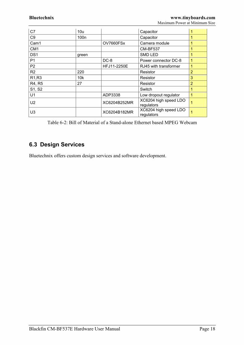
6.2 Stand-alone Ethernet based MPEG Webcam
The CM-BF537E module can be used as a stand-alone module for a camera system requiring
only power supply and the direct attachment of a compatible video camera. A camera kit
including drivers can be purchased form Bluetechnix: KIT-CAM-OV (O.Nr 100-9901)
Figure 6-2: Stand-alone Ethernet based MPEG Webcam
Designator Value Type Description Quantity
C3, C4, C5, C6, C8 1u Capacitor 6
Bluetechnix www.tinyboards.com Maximum Power at Minimum Size
Blackfin CM-BF537E Hardware User Manual Page 18
C7 10u Capacitor 1
C9 100n Capacitor 1
Cam1 OV7660FSx Camera module 1
CM1 CM-BF537 1
DS1 green SMD LED 1
P1 DC-8 Power connector DC-8 1
P2 HFJ11-2250E RJ45 with transformer 1
R2 220 Resistor 2
R1,R3 10k Resistor 3
R4, R5 27 Resistor 2
S1, S2 Switch 1
U1 ADP3338 Low dropout regulator 1
U2 XC6204B252MR XC6204 high speed LDO regulators
1
U3 XC6204B182MR XC6204 high speed LDO regulators
1
Table 6-2: Bill of Material of a Stand-alone Ethernet based MPEG Webcam
6.3 Design Services
Bluetechnix offers custom design services and software development.

Bluetechnix www.tinyboards.com Maximum Power at Minimum Size
Blackfin CM-BF537E Hardware User Manual Page 19
7 Known Bugs
NONE
Table 7-1: Known Bugs
Bluetechnix www.tinyboards.com Maximum Power at Minimum Size
Blackfin CM-BF537E Hardware User Manual Page 20
8 Product Changes
Version Changes
Table 8-1: Product Changes

Bluetechnix www.tinyboards.com Maximum Power at Minimum Size
Blackfin CM-BF537E Hardware User Manual Page 21
9 Document Revision History
Date Document Revision
2007-05-03 Updated missing reference
2007-04-05 Several Changes and removing BGA option
2006-04-26 Updated Figures, Pin40 and PIN22 names
2006-04-02 Updated table 2-3 PF9 instead of P8, added VA25 on table 2-5 and
fixed memory map in table 2-6
2005-10-13 Correct boot mode description
2005-10-11 New images
2005-08-16 Refinement of documentation
2005-06-28 First release V1.0 of the document
Table 9-1: Revision History

Bluetechnix www.tinyboards.com Maximum Power at Minimum Size
Blackfin CM-BF537E Hardware User Manual Page 22
A List of Figures and Tables
Figures
Figure 1-1: Main components of the CM-BF537E Core Module .............................................. 1
Figure 2-1: Detailed Block Diagram .......................................................................................... 3
Figure 3-1: Mechanical outline and Bottom Connectors (top view) .......................................... 6
Figure 3-2: Side View with Connector mounted ........................................................................ 6
Figure 3-3: Connector footprint for the Core Module (top view) .............................................. 7
Figure 3-4: Core Module (component side) ............................................................................... 8
Figure 3-5: Schematic Symbol of Module ................................................................................. 9
Figure 3-6: Schematic for RJ45 Connection ............................................................................ 13
Figure 4-1: Test Points of the Core Module (top view) ........................................................... 14
Figure 6-1: Configuration with Ethernet and JTAG Connector ............................................... 16
Figure 6-2: Stand-alone Ethernet based MPEG Webcam ........................................................ 17
Tables
Table 2-1: Memory Map ............................................................................................................ 4
Table 3-1: Baseboard connector types........................................................................................ 7
Table 3-2: Module connector types ............................................................................................ 7
Table 3-3: Connector P1 pin assignment ................................................................................. 10
Table 3-4: Connector P2 pin assignment ................................................................................. 11
Table 3-5: Pin description of all non Processor Pins on the CM-BF537E ............................... 12
Table 3-6: Parts List RJ45 ........................................................................................................ 13
Table 6-1: Bill of Material of Sample Schematic ..................................................................... 17
Table 6-2: Bill of Material of a Stand-alone Ethernet based MPEG Webcam ........................ 18
Table 7-1: Known Bugs ........................................................................................................... 19
Table 8-1: Product Changes ..................................................................................................... 20
Table 9-1: Revision History ..................................................................................................... 21