blah1000 amplifier 700-900mhz
TRANSCRIPT
BLAH1000
Amplifier 700-900MHzOperating & Service Manual
Version
001
The information in this manual may be altered without notice.
BRUKER accepts no responsibility for actions taken as a result of use of this ma-nual. BRUKER accepts no liability for any mistakes contained in the manual, lead-ing to coincidental damage, whether during installation or operation of the instru-ment. Unauthorised reproduction of manual contents, without written permission from the publishers, or translation into another language, either in full or in part, is forbidden.
This manual describes the units as they are at the time of printing. On request, the manufacturer shall supply circuit diagrams, lists of components, descriptions, cali-brating instructions and any other information for use by qualified personnel of the user, in charge of repairing the parts of the unit which have been stated by the manufacturer to be "repairable". Such supply shall in no event constitute permis-sion to modify or repair the units or approval of the same.
All rights reserved for the units, circuits, processes and appellations mentioned herein.
This unit is not designed for any type of use which is not specifically described in this manual. Such use may be hazardous.
This manual was written by
BRZUCZKIEWICZ Serge
© July 1, 2004: Bruker Biospin SA
Wissembourg, France
P/N: Z31654DWG-Nr: 1360.001

Contents
Contents .............................................................. iii
1 General information .............................................. 51.1 Introduction ......................................................................... 51.2 Package .............................................................................. 51.3 Initial Turn On Procedure ..................................................... 6
2 Safety .................................................................... 72.1 Labels ................................................................................. 7
Dangerous area .............................................................. 7Name plate ..................................................................... 7
3 Installation ............................................................ 93.1 Initial inspection .................................................................. 9
Mechanical check ........................................................... 9Claim for damage ........................................................... 9Reshipment and repackaging requirements ..................... 9Auxiliary kit ..................................................................... 9
3.2 Installation requirements ................................................... 10Bench operation ........................................................... 10Cooling and ventilation ................................................. 10
3.3 Power requirements .......................................................... 103.4 System check .................................................................... 103.5 Initial turn on procedure ..................................................... 11
4 Operation ............................................................ 134.1 Front Panel ....................................................................... 13
Indicators ...................................................................... 13Connectors ................................................................... 14Interface Connector RS485 ........................................... 14
4.2 Rear Panel ........................................................................ 16Rear panel supply connector ......................................... 16
5 Technical description ......................................... 175.1 System Overview ............................................................... 175.2 Theory of Operation ........................................................... 20
RF Path ........................................................................ 20Control Board ............................................................... 21Supply Status Board ..................................................... 21Fan Status Board .......................................................... 21Status Led Board .......................................................... 22
BLAH1000 Version 001 iii

Contents
6 Specifications ...................................................... 236.1 General specifications Solid output H1000 ........................ 236.2 General specifications High Resolution output H100 .......... 246.3 BLAH1000 Common Characteristics ................................. 25
Figures ................................................................. 27
Tables .................................................................. 29
iv BLAH1000 Version 001
1General information 1
Introduction 1.1
The BLAH1000 700-900Hz Pulse Power Amplifier is a broadband linear amplifier specifically designed for High Field Nuclear Magnetic Resonance (NMR) applica-tions.
The class AB linear amplifier provides 1000W peak power over the frequency range 650-900MHz on the H1000 output for the Solid applications and 100W peak power on the H100 output for the High Resolution applications.
The amplifier is realised with N-CHANNEL MOS RF POWER FETs. The unit sup-ports pulse width of max 100ms and duty cycle of 2% at full power.
Its built-in control and protection circuitry allows continues wave at lower power, maintaining a 50W average power on the H1000 output, and 50W average power on the H100 output.
The electronic protection circuitry has been designed to protect against :
• Excessive power output level (overdrive)
• Excessive pulse repetition rate (over duty-cycle protection)
• Excessive pulse duration (over pulse- width)
• Excessive reflected RF power (mismatch)
• Overheat protection
The amplifier is powered by an external power supply assembly, housed in a 19" rack cabinet.
Package 1.2
• The amplifier unit BLAH1000 700-900MHz has the P/N: W1345065
• The power supply unit ALIM DEC 28V/100A has the P/N: W1303539
• The commercial BRUKER P/N for the 2 units is: W1303458
BLAH1000 Version 001 5 (31)
General information
Initial Turn On Procedure 1.3
The AC input voltage for the power supply unit must be in the range 188 to 264VAC 50/60Hz.
The power supply outputs are at +30VDC and the connector must be connected to the amplifier unit.
At turn on the power supply, the front panel displayed following status:
• The 2 channels A,B (+30V) are ON
• The +15V, -15V and + 5V are ON.
The amplifier unit displayed following status:
• The +30V, +15V, -15V and +5V are ON.
The RF power outputs must be connected to the probe or at 50Ω load. The BLNK in is a TTL pulse signal with correct polarity : low (0V) = RF pulse out allowed (standard configuration).
The RF in is the RF signal of +4dBm max. at frequencies between 650 and 900MHz. The SEL H1000.H100 needs a TTL level high (5V) or no connection for HIGH RESOLUTION H100, and a low level (0V) for SOLID H1000.
The RS485 connectors sets the interface between amplifier and spectrometer.
6 (31) BLAH1000 Version 001

2Safety 2
Labels 2.1
Labels are provided to alert operating and service personnel to conditions that may cause personal injury or damage to the equipment from misuse or abuse. Please read the labels and understand their meaning.
Dangerous area 2.1.1
WARNING ! High Voltage.
Name plate 2.1.2
The BLAH1000 Amplifier 700-900MHz can be identified by a name plate at the front panel of the unit which has following information:
• (A) Part Number This field indicates the assembly number which identifies the part number of the product.
• (B) Variant This field indicates the variant number which identifies the production category of the product. The default variant is 00.
• (C) ECL This field indicates the revision number which identifies the product configura-tion. The initial revision is 0.00.
• (D) Serial Number This field indicates the manufacturing number which identifies the serial number of the product.
• (E) Type This field contains the designation of the product.
Disconnectline cord
before opening
A / / /B C DEF
BLAH1000 Version 001 7 (31)

Safety
• (F) Information This field contains information about the useful frequency range of the pro-duct.
8 (31) BLAH1000 Version 001
3Installation 3
Initial inspection 3.1
Mechanical check 3.1.1
If damage of the shipping carton is evident, request the carrier's agent be present when the instrument is unpacked. Check the equipment for damage and inspect the cabinet and panel surfaces for dents and scratches.
Claim for damage 3.1.2
If the unit is mechanically damaged or fails to meet specifications upon receipt, notify BRUKER or our representative immediately. Retain the shipping carton and packing material for the carriers inspection as well as for subsequent use in re-turning the unit if necessary.
Reshipment and repackaging requirements 3.1.3
Whenever possible, the original carton and packing material should be used for reshipment. If the original packing material is not available, wrap the instrument in heavy paper or plastic. Use a strong shipping container. If a cardboard is used, it should be at least 200 lbs. test material.
Use shock absorbing material around all sides of the instrument to provide a firm cushion and to prevent movement inside the container wall on each side. Protect the front panel by means of cardboard spacers inserted between the front panel and the shipping carton. Make sure that the instrument cannot move in the con-tainer during shipping. Seal the carton with a good grade of shipping tape and mark the container :
" FRAGILE ELECTRONIC INSTRUMENT."
Auxiliary kit 3.1.4
The BLAH1000 is shipped with an accessories kit containing following items :
• Manual
• Line Cord
• Switched Power Supply in separate carton
The BLAH1000 (P/N:W1345065) with the POWER SUPPLY (P/N:W1303539) is commercialized under the BRUKER Part Number W1303458.
BLAH1000 Version 001 9 (31)

Installation
Installation requirements 3.2
No special precautions are necessary. Mount the equipment in an area which is relatively free of vibration, and has sufficient room for cable connections.
Bench operation 3.2.1
The units can be placed onto a secure flat surface.
Cooling and ventilation 3.2.2
No specific cooling or ventilation is required. It should, however, be in an environ-ment which conforms the 0° - 45°C (32°F - 113°F) specification, and in an area that does not obstruct the free flow into and out of the unit.
Power requirements 3.3
The BLAH1000 is designed to be powered by means of an additional switched power supply (BRUKER Part Number P/N : W1303539).
The connection to this power supply is realized via a 500mm cable fitted with a 15 pins DIN 41612-HERNI female connector, and coming out from the rear panel of the amplifier.
This switched power supply provides all the voltages necessary to the BLAH1000. ( 5 x +30V / +15V / -15V / +5V / GND)
System check 3.4
Before applying power for the first time the following items should be checked :
• The AC input voltage from the Power Supply must be compatible with 188 to 264VAC range.
• An external blanking (gating) pulse must be supplied to the amplifier in order for the unit to function. Ensure that this pulse is of proper level and logic pola-rity.
• The BLAH1000 has a nominal input level of +4dBm. Ensure that the system drivers are operating at these levels.
10 (31) BLAH1000 Version 001
Initial turn on procedure
Initial turn on procedure 3.5
The following list describes how to turn on the BLAH1000 and what should be seen as this occurs.
Before starting this procedure, make sure that you have properly followed instruc-tions in the section "System check" on page 10".
1. Connect the amplifier to the power supply and turn the circuit breaker, to ON.
2. Observe the indicators on the front panel of the power supply : - The five channels +28V (+30 V) ON LED's will illuminate - The +15V, -15V and + 5V ON LED's will illuminate
3. Observe the indicators on the front panel of the amplifier : - The +30V, +15V , -15V and +5V ON LED's will illuminate
4. System is now fully operational.
BLAH1000 Version 001 11 (31)
Installation
12 (31) BLAH1000 Version 001
4Operation 4
Front Panel 4.1
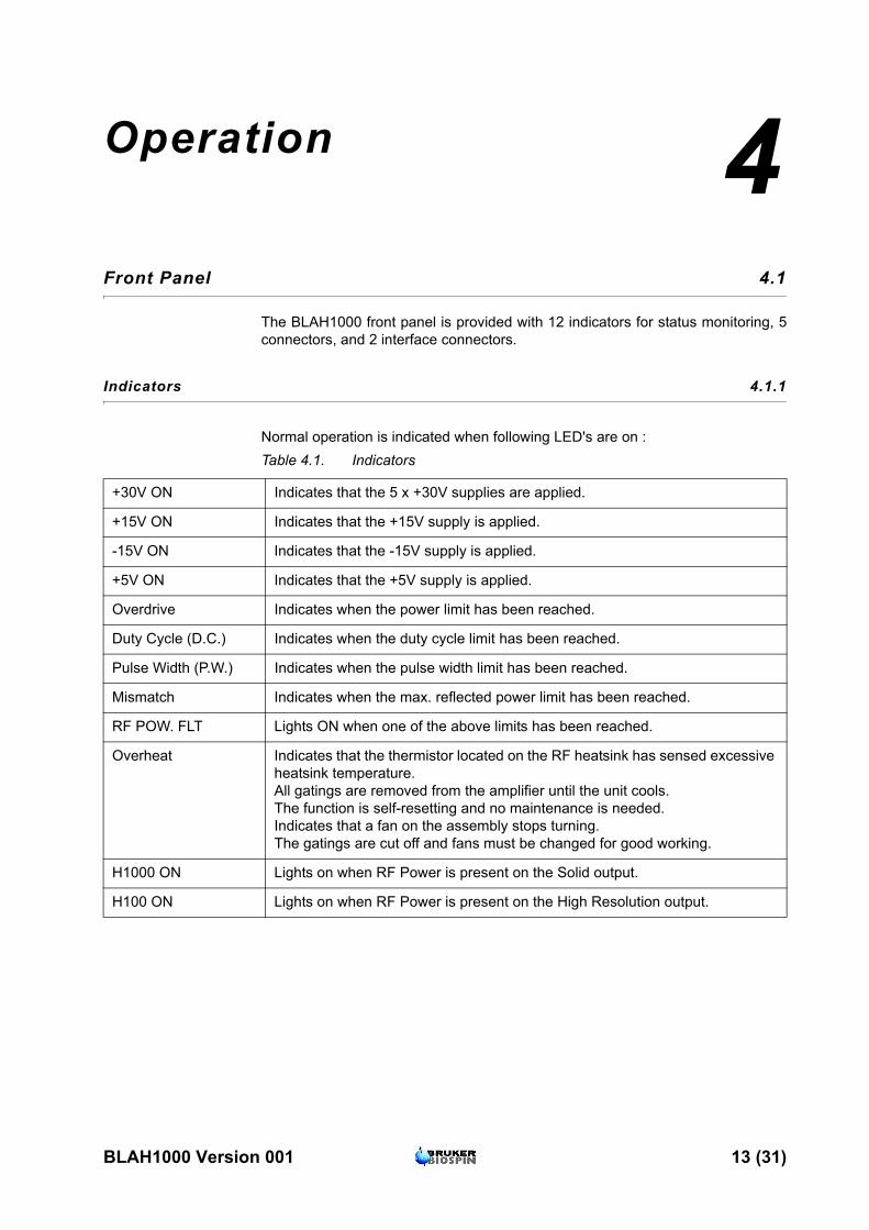
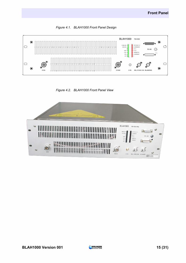
The BLAH1000 front panel is provided with 12 indicators for status monitoring, 5 connectors, and 2 interface connectors.
Indicators 4.1.1
Normal operation is indicated when following LED's are on :Table 4.1. Indicators
+30V ON Indicates that the 5 x +30V supplies are applied.
+15V ON Indicates that the +15V supply is applied.
-15V ON Indicates that the -15V supply is applied.
+5V ON Indicates that the +5V supply is applied.
Overdrive Indicates when the power limit has been reached.
Duty Cycle (D.C.) Indicates when the duty cycle limit has been reached.
Pulse Width (P.W.) Indicates when the pulse width limit has been reached.
Mismatch Indicates when the max. reflected power limit has been reached.
RF POW. FLT Lights ON when one of the above limits has been reached.
Overheat Indicates that the thermistor located on the RF heatsink has sensed excessive heatsink temperature.All gatings are removed from the amplifier until the unit cools.The function is self-resetting and no maintenance is needed.Indicates that a fan on the assembly stops turning.The gatings are cut off and fans must be changed for good working.
H1000 ON Lights on when RF Power is present on the Solid output.
H100 ON Lights on when RF Power is present on the High Resolution output.
BLAH1000 Version 001 13 (31)
Operation
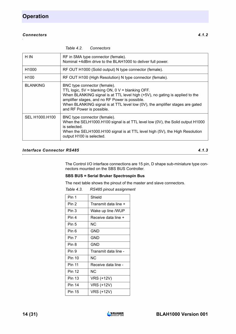
Connectors 4.1.2
Interface Connector RS485 4.1.3
The Control I/O interface connections are 15 pin, D shape sub-miniature type con-nectors mounted on the SBS BUS Controller.
SBS BUS = Serial Bruker Spectrospin Bus
The next table shows the pinout of the master and slave connectors.
Table 4.2. Connectors
H IN RF in SMA type connector (female).Nominal +4dBm drive to the BLAH1000 to deliver full power.
H1000 RF OUT H1000 (Solid output) N type connector (female).
H100 RF OUT H100 (High Resolution) N type connector (female).
BLANKING BNC type connector (female).TTL logic, 5V = blanking ON, 0 V = blanking OFF.When BLANKING signal is at TTL level high (+5V), no gating is applied to the amplifier stages, and no RF Power is possible.When BLANKING signal is at TTL level low (0V), the amplifier stages are gated and RF Power is possible.
SEL H1000.H100 BNC type connector (female).When the SELH1000.H100 signal is at TTL level low (0V), the Solid output H1000 is selected.When the SELH1000.H100 signal is at TTL level high (5V), the High Resolution output H100 is selected.
Table 4.3. RS485 pinout assignment
Pin 1 Shield
Pin 2 Transmit data line +
Pin 3 Wake up line /WUP
Pin 4 Receive data line +
Pin 5 NC
Pin 6 GND
Pin 7 GND
Pin 8 GND
Pin 9 Transmit data line -
Pin 10 NC
Pin 11 Receive data line -
Pin 12 NC
Pin 13 VRS (+12V)
Pin 14 VRS (+12V)
Pin 15 VRS (+12V)
14 (31) BLAH1000 Version 001
Front Panel
Figure 4.1. BLAH1000 Front Panel Design
Figure 4.2. BLAH1000 Front Panel View
H1000 ON
+30V
+15V
-15V
+5V
RF POW. FLT
OVERHEAT
OVERDRIVE
D. C.
P. W.
MISMATCH
H100 ON
0
12345
6789ABC
DEFRS 485
700-900BLAH1000
H1000 H IN SEL H1000.100 BLANKINGH100
BLAH1000 Version 001 15 (31)

Operation
Rear Panel 4.2
The rear Panel of the BLAH1000 Amplifier is free of elements in exception of a 500mm cable fitted with a 15 pin DIN 41612-HERNI female connector, coming out from the rear panel of the amplifier.
Rear panel supply connector 4.2.1
NoteDGND = Digital Ground for ±15V and +5V PGND = Power Ground for 5 x +30V
Table 4.4. DIN 41612-HERNI Pin assignment
Pin z4 +5V
Pin z8 +15V
Pin z12 -15V
Pin z16 +30V
Pin z20 +30V
Pin z24 +30V
Pin z28 +30V
Pin z32 +30V
Pin d6 not connected
Pin d10 DGND
Pin d14 PGND
Pin d18 PGND
Pin d22 PGND
Pin d26 PGND
Pin d30 PGND
16 (31) BLAH1000 Version 001
5Technical description 5
System Overview 5.1
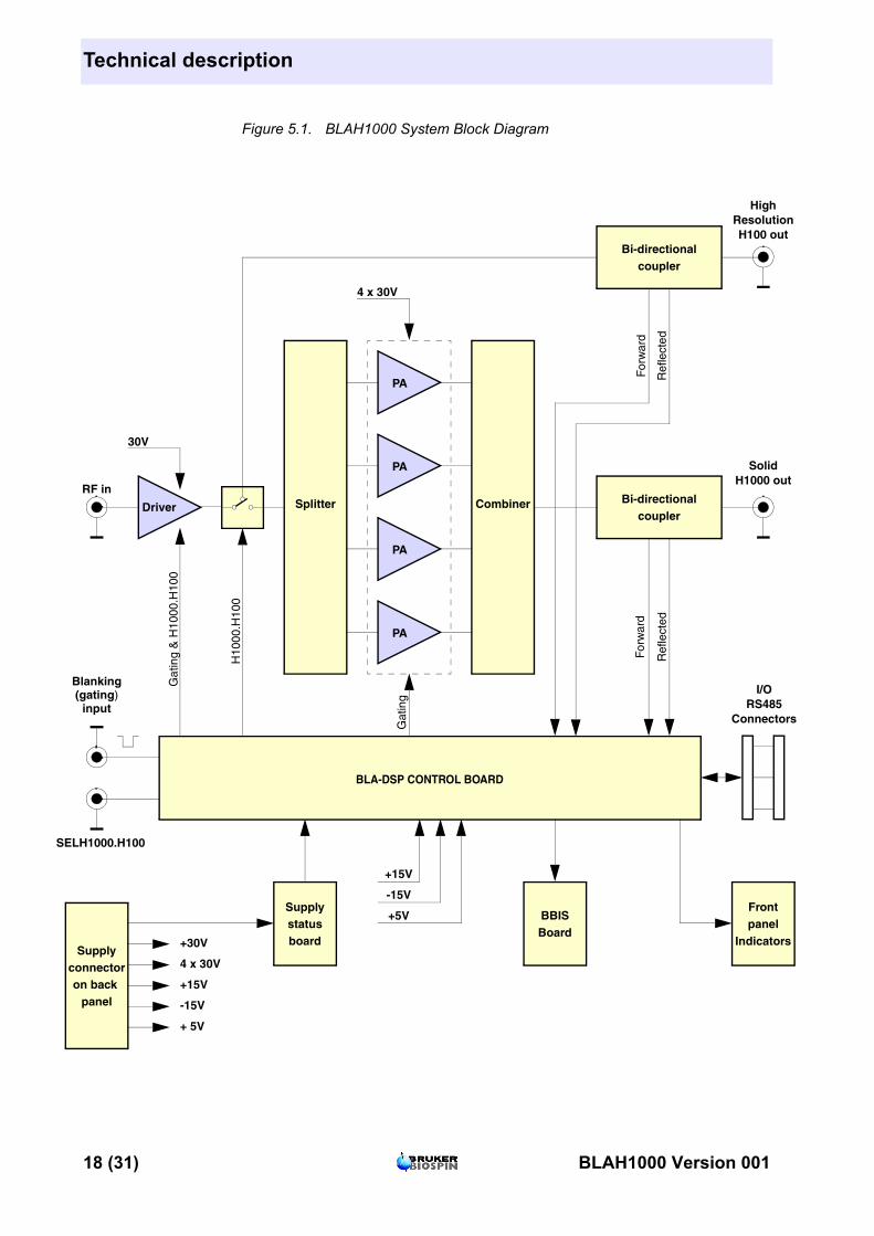
The BLAH1000 amplifier requires the additional Bruker Power Supply P/N : W1303539, to provide:
• A RF Output of 1000W and more on the Solid Output H1000, over the full fre-quency range 650 to 850MHz and 900W at 900MHz, when selected for Solid operation with SELH1000.H100 command controlled at TTL level low.
• A RF Output of 100W and more on the High Resolution Output H100 over the same full frequency range 650 to 900MHz when selected for High Resolution operation by SELH1000.H100 controlled at TTL level High.
The RF section of the system consists of a linear module BLMH1000 mounted around a single, self-contained Push and Pull fan assemblies, heatsink.
A linear class A / AB driver uses the bias voltage for 'blanking' the MOSFET tran-sistors, and provide the power switched between H100 output and the 4 ways power splitter which drives the 4 power amplifiers .The switch is a power RF relay driven by the control SEL H1000.H100.
The 4 amplifiers are combined in a 4 ways power combiner to get the output pow-er at H1000.
Each output pass through a bi-directional Coupler to end at the front panel con-nectors.
The entire system is controlled by a Digital Signal Processing control board:
• To get information of type of amplifier and limitations, and to display power level or reflected power.
• To set protection on amplifiers and display defaults in case of excessive power, duty cycle pulse width, reflected power, and overheat.
BLAH1000 Version 001 17 (31)
Technical description
c
tn
t
rs
SE
s
Figure 5.1. BLAH1000 System Block Diagram
CombinerSplitterDriver
PA
Supplyonnectoron back
panel
Bi-directionalcoupler
BBISBoard
BLA-DSP CONTROL BOARD
Blanking(gating)
input
+15V
-15V
+5V
30V
RF in
For
war
d
Ref
lect
ed
Gat
ing
& H
1000
.H10
0
4 x 30V
+ 5V
-15V
+15V
4 x 30V
Gat
ing
H10
00.H
100
Ref
lect
ed
For
war
d
H100 ouResolutio
H1000 ouSolid
High
ConnectoRS485
I/O
LH1000.H100
Supplystatusboard+30V
Frontpanel
Indicator
PA
PA
PA
Bi-directionalcoupler
18 (31) BLAH1000 Version 001
System Overview
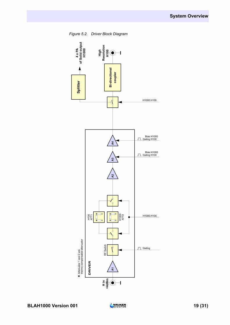
Figure 5.2. Driver Block Diagram
of S
olid
out
put
H10
00*A
ttenu
ator
1 a
nd 2
are
ther
mo
com
pens
ated
atte
nuat
or
H in
+4dB
m
H1000.H100
H10
0
H10
00
A2
A3
A4
DR
IVE
R
RF
Sw
itch
Bi-d
irect
iona
lco
uple
r
H1000.H100
4 x
PA
H10
0 R
esol
utio
nH
igh
Spl
itter
Bias H1000Gating H100
ATT2
A1
ATT1
Gating
Bias H1000Gating H100
BLAH1000 Version 001 19 (31)
Technical description
Theory of Operation 5.2
RF Path 5.2.1
RF PreamplifierThe first section of the driver is an hybrid amplifier to get a good noise factor (7dB), followed by 2 switched TPAD and attenuators, one for the channel H100, one for the channel H1000 and followed by a second hybrid amplifier, a TPAD and finally 2 push-pull MOSFET transistors in class AB to built a 36dB gain block.
The switched attenuator is needed to minimize gain when operating in Solid mode H1000 and to get full gain in mode H100. These attenuators are in fact tiled in a variable attenuator to adjust gain and a TPAD for compensation of power level drift of the amplifier with temperature.
Both transistors are blanked with the Blanking signal to achieve good isolation of the amplifier without RF.
RF DriverThe second section of the driver includes a first MOSFET transistor, followed by a push-pull stage of 2 MOSFET transistors coupled with a -3dB splitter/combiner at input and output.
This stage achieves a gain of 12dB and is also blanked with a blanking signal without RF signal.
The total linear gain is about 48dB for the driver. The direct nominal output power is 130W at the module output and it is operating at +30V supply.
RF Relay H1000.H100The coaxial RF relay switches the RF Power from the driver via a bi-directional coupler to the High Resolution output H100 on side of the front panel, when the SEL H1000.H100 signal is controlled to TTL level high or not connected.
When controlled by SEL H1000.H100 signal at TTL low, the relay switches the output of the driver to the 4 inputs of the Power Amplifiers via a 4 ways -6dB pow-er splitter, to built the Solid output H1000.
RF Coupler H100The H100 bi-directional coupler provides an approximate 1V peak DC signal for full 100W (envelope or RF signal) for monitoring of the output power. It also gives a signal image of the reflected power by the load (probe).
Both signals, forward and reflected, are analyzed by the BLA DSP control board for monitoring and protection setting on the H100 output.
RF Power AmplifierEach of the 4 power amplifiers includes one MOSFET transistor to increase gain of the chain and 4 MOSFET transistors coupled with a -6db 4 ways splitter/com-biner. The 4 amplifiers are blanked to minimize noise at output and each delivers a power of about 320W. The gain of the stage is about 14dB.
The 4 power amplifiers are operating at + 30VDC supplies.
20 (31) BLAH1000 Version 001
Theory of Operation
RF CombinerThe RF combiner is a 4 ways -6dB power combiner which couples the 4 outputs of the power amplifiers to get a power of 1000W through the bi-directional coupler to the front panel output H1000. The total gain of the amplifier is about 60dB.
RF Coupler H1000The H1000 bi-directional coupler provides about 1V peak DC signal for full 1000W (envelope or RF signal) for monitoring of the output power. It also gives a signal image of the reflected power by the load (probe).
Both signals, forward and reflected, are analyzed by the control board for monito-ring and protection setting on the H1000 output.
Control Board 5.2.2
The BLA DSP Control Board has 3 principal functions:
1. To distribute the blanking signals to the amplifiers. In case of default, the pro-tection disables the blanking with a certain time delay loop; this may cut up the RF signal and display the status of the default with the same time loop. When the default is corrected, the RF output is allowed again. When working on High Resolution channel, only the blanking signal on the driver H100 is needed, so blanking on PA is disabled. When working on Solid channel H1000 the blanking signal is needed on all amplifiers (driver and power amplifiers).
2. To send information of power, defaults and status to the console. The SBS Bus Controller, via the RS485 connector, reads also information for identification of the amplifier (Bruker Board Identification System = BBIS ).
3. To set limitations and protections to the amplifier when a default condition oc-curs; overdrive, pulse width, duty cycle, reflected power, overheat, supplies de-fault, fans default.
Supply Status Board 5.2.3
This board gives the information of the status of the power supplies. A defect on one or more of the supplies is read by the control board, and in case of, the gating signal is disabled while the defect is visualized on the front panel led display.
Fan Status Board 5.2.4
The fan status board gives information of the status of the two push and pull fan assemblies. A defect on the fans is read by the control board, the gating signal is disabled, and the "overheat" led of the front panel Status led display lights ON.
BLAH1000 Version 001 21 (31)
Technical description
Status Led Board 5.2.5
The Status Led Board, on the front panel of the amplifier, displays overstress func-tions, supplies status, and so on, as described in ""Front Panel" on page 13 and "Control Board" on page 21.
22 (31) BLAH1000 Version 001

6Specifications 6
General specifications Solid output H1000 6.1
Table 6.1. BLAH1000 Solid Output H1000 Specifications
Frequency range 650 to 900MHz
Linear gain 60dB typical (@ Pin = -10dBm 800MHz)
Gain flatness ±2dB max.
Peak pulsed power 1000W typical (@ nominal input +4dBm)900W @ 900MHz
CW power 50W max.
Linear output power 600W min. @ 1dB compression
Amplifier biasing Class AB Operation
Blanking delay time < 1µs typical
RF rise time < 70ns
RF fall time < 50ns
Input/output impedance 50Ω
Output noise power -107dBm @ 1Hz unblankedThermal Noise -20dBm blanked
Pulse width (limited) 100ms @ 1000W (up to CW @ 50W)
Duty cycle (limited) 2% @ 1000W (up to 100% @ 50W)
Amplitude droop < 8% @ 1000W for 100ms pulse width< 5% @ 1000W for 10ms pulse width
Amplitude stability v. temperature ± 0,2% / °C
Input V.S.W.R. 1.5 max.
Input power max. +8dBm
Noise figure 7dB typical
BLAH1000 Version 001 23 (31)
Specifications
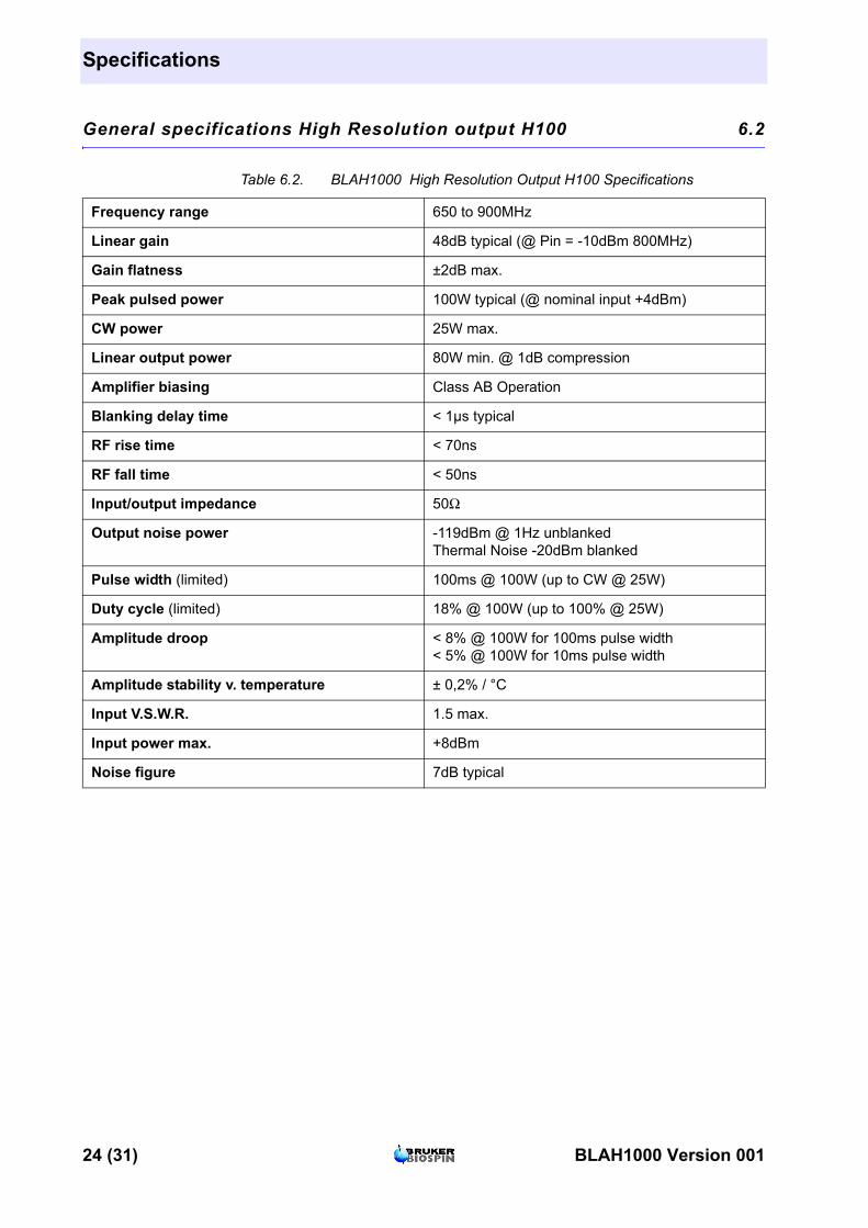
General specifications High Resolution output H100 6.2
Table 6.2. BLAH1000 High Resolution Output H100 Specifications
Frequency range 650 to 900MHz
Linear gain 48dB typical (@ Pin = -10dBm 800MHz)
Gain flatness ±2dB max.
Peak pulsed power 100W typical (@ nominal input +4dBm)
CW power 25W max.
Linear output power 80W min. @ 1dB compression
Amplifier biasing Class AB Operation
Blanking delay time < 1µs typical
RF rise time < 70ns
RF fall time < 50ns
Input/output impedance 50Ω
Output noise power -119dBm @ 1Hz unblankedThermal Noise -20dBm blanked
Pulse width (limited) 100ms @ 100W (up to CW @ 25W)
Duty cycle (limited) 18% @ 100W (up to 100% @ 25W)
Amplitude droop < 8% @ 100W for 100ms pulse width< 5% @ 100W for 10ms pulse width
Amplitude stability v. temperature ± 0,2% / °C
Input V.S.W.R. 1.5 max.
Input power max. +8dBm
Noise figure 7dB typical
24 (31) BLAH1000 Version 001
BLAH1000 Common Characteristics
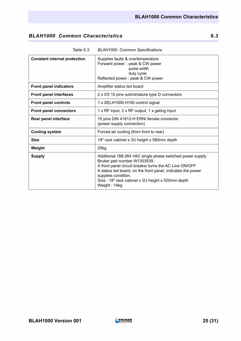
BLAH1000 Common Characteristics 6.3
Table 6.3. BLAH1000 Common Specifications
Constant internal protection Supplies faults & overtemperatureForward power : peak & CW power
pulse widthduty cycle
Reflected power : peak & CW power
Front panel indicators Amplifier status led board
Front panel interfaces 2 x I/O 15 pins subminiature type D connectors
Front panel controls 1 x SELH1000.H100 control signal
Front panel connectors 1 x RF input, 2 x RF output, 1 x gating input
Rear panel interface 15 pins DIN 41612-H ERNI female connector (power supply connection)
Cooling system Forced-air cooling (from front to rear)
Size 19" rack cabinet x 3U height x 580mm depth
Weight 25kg
Supply Additional 188-264 VAC single phase switched power supplyBruker part number W1303539.A front panel circuit breaker turns the AC Line ON/OFFA status led board, on the front panel, indicates the powersupplies condition.Size : 19" rack cabinet x 2U height x 520mm depthWeight : 14kg
BLAH1000 Version 001 25 (31)
Specifications
26 (31) BLAH1000 Version 001

Figures
1 General information 5
2 Safety 7
3 Installation 9
4 Operation 13Figure 4.1. BLAH1000 Front Panel Design ........................................... 15Figure 4.2. BLAH1000 Front Panel View .............................................. 15
5 Technical description 17Figure 5.1. BLAH1000 System Block Diagram ...................................... 18Figure 5.2. Driver Block Diagram .......................................................... 19
6 Specifications 23
BLAH1000 Version 001 27 (31)

Figures
28 (31) BLAH1000 Version 001
Tables
1 General information 5
2 Safety 7
3 Installation 9
4 Operation 13Table 4.1. Indicators ...................................................................... 13Table 4.2. Connectors .................................................................... 14Table 4.3. RS485 pinout assignment .............................................. 14Table 4.4. DIN 41612-HERNI Pin assignment ................................. 16
5 Technical description 17
6 Specifications 23Table 6.1. BLAH1000 Solid Output H1000 Specifications ............... 23Table 6.2. BLAH1000 High Resolution Output H100 Specifications 24Table 6.3. BLAH1000 Common Specifications ............................... 25
BLAH1000 Version 001 29 (31)

Tables
30 (31) BLAH1000 Version 001

Notes
BLAH1000 Version 001 31 (31)
Lastpage