semspub.epa.gov · introduction ~)"blasting" is performed to break rock so that it may be...
TRANSCRIPT

Jg Construction Planning Equipment Sixth Edition ~ and Methods CHAPTER
BLASTING ROCK --- -shyofEngineering bullDepartment ofCivil and Environmental
- Construction Equipment and Methods
Spring 2003
Department of Civil and Environmental Engineering
University of Maryland College Park
By
Dr Ibrahim Assakkaf ENCE 420
INTRODUCTION
amp)BLAST DESIGN is not an exact science but by considering the rock formation it is possible to produce the desired result
ampThis is a step-by-step procedure for designing the blast hole layout and calculating the amount of explosives for blasting rock
INTRODUCTION
~) Blasting is performed to break rock so that it may be quarried for processing in an aggregate production operation or to excavate a right-of-way
~ Blasting is accomplished by discharging an explosive that has either been placed in an unconfined manner such as mud capping boulders or is confined as in a borehole
INTRODlJCTION
CD There are two forms of energy released when high explosives are detonated shock and gas An unconfined charge works by shock energy whereas a confined charge has a high gas energy output
There are many types of explosives and methods for using them
[2]811ast design [2]Powder factor [2]Vibration [2]Trench rock [2]Presplitting [2]Production
Face Bench height
Burden distance Spacing
Blasthole depth Stemming
Subdrilling
Subdrilling J
OVERVIEW
rr Rock breakage results from gas pressure in the blasthole
~ Radial crackins
rr Individual wedge rr Flexural rupture
rr Stiffness ratio
bench height burden distance
BURDEN Burden distance is the most critical dimension inmiddot- _ ~
shy shy~_-t
blast design middot middot lt-~-- It is the dista ~ ~middot~ ~=~middot to the free fa~~_ middot of the excavation
bullbull bull
COMMERCIAL EXPLOSIVES
c~There are four main categories of commercial high explosives 1 Dynamite
2 Slurries
3 ANFO and
4 Two-component explosives
COMMERCIAL EXPLOSIVES
e The first three categories dynamite slurries and ANFO are the principal explosives used for borehole charges
o Two-component or binary explosives are normally not classified as an explosive until mixed
DYNAMITE
ctDynamite is nitroglycerin-based product
~~ It is the most sensitive of all the generic classes of explosives in use nowadays
ct lt is available in many grades and sizes to meet the requirements of a particular job
c The approximate strength of a dynamite is specified as a percentage (weight of nitroglycerin to the total weight of a cartridge
c~ Cartridges vary in size from approximately 1 to 8 in in diameter and 8 to 24 in long
c Dynamite is used extensively for charging boreholes especially for the smaller sizes
13 BLASTING ROCK
Dynamite Cartridge
oSlurries is generic term used for both water gels and emulsion
cbull They are water-resistant explosive mixtures of ammonium nitrate and a fuel sensitizer
c The primary sensitizing methods are introduction of air throughout the mixture
the addition of aluminum particles
or the addition of nitrocellulose
~ In comparison to different explosives (such as ANFO) slurries have a higher cost per pound and have less energy
However their higher cost can be justified if used in wet condition
They are not water-sensitive
e An advantage of slurries over dynamite is that the separate ingredients can be hauled to the project in bulk and mixed immediately before loading the blastholes
ct ANFO is blasting agent that is produced by mixing prilled ammonium nitrate and fuel oil
~~ This explosive is used extensively on construction project and represents about 80dego of all explosives used in the United States
ct ANFO is the cheapest and safest among others
ANFQ Texas City 16 April1947
ANFO is an explosive used extensively on construction projects
~The ANFO is made by blending 35 quarts of fuel oil with 100 lb of ammonium nitrate blasting prills
~ This the optimum ratio
~~ The detonation efficiency is controlled by this ratio
c~ Because the mixture is free-flowing it can be blown or augered from the bulk trucks directly into the blasholes
INITIATING AND DELAY DEVICES
c lt is common practice to fire several holes or rows of holes at one time
n Fragmentation backbreake vibration and violence of a blast are all controlled by the firing sequence of the individual blastholes
INITIATING AND DELAY DEVICES
cThe order and timing of the detonation of the individual holes is regulated by the initiation system Electric and non-electric initiation systems are available
cbullWhen selecting the proper systemj one should consider both blast design and safety
ELECTRIC BLASTING CAPS
e With an electric cap an explosion is caused by passing an electric current through a wire bridge similar to an electric light bulb filament
e A current of approximately 15 amps heats the bridge to ignite a heat- sensitive flash compound
e The ignition sets off a primer which in turn fires a base charge in the cap
DELAY BLASTING SYSTEMS
~= Delay blasting caps are used to obtain a specified firing sequence
c~These caps are available for delay intervals varying from a small fraction of second to about 7 seconds
c~When explosives charges in two or more rows of holes parallel to the face are fired in one shot it is desirable to fire the charges in the holes nearest the face a short time ahead of those in the second row
DELAY BLASTING SYSTEMS
~This procedure will reduce the burden in the second row and hence will permit the explosives in the second row to break more effectively
c~ ln the case of more than two rows of explosives this same delayed firing sequence will be followed for each success1ve row
DETONATING CORD
~~The detonating cord is a nonshyelectric initiation system consisting of a flexible cord having a center core of high explosive
~== It is used to detonate dynamite and other cap-sensitive explosives
ROCK BREAKAGE
cbullThe major mechanisms of rock breakage result from the sustained gas pressure buildup in the borehole by the explosion
~~ First this pressure will cause radial cracking Such cracking is similar to what happens in the case of frozen water pipes-a longitudinal split occurs parallel to the axis of the pipe
ROCK BREAKAGE
~~A borehole is analogous to the frozen ~ in that it is a cylindrical pressure vessel But there is a difference in the rate of loading A blasthole is pressurized instantaneously Failure therefore instead of being at the one weakest seam is in many seams parallel to the borehole
BLAST DESIGN
CIEvery blast must be designed to meet the existing conditions of the rock formation and overburden and to produce the desired final result There is no single solution to this problem
BLAST DESIGN
cbullRock is not a homogeneous material There are fracture planes seams and changes in burden to be considered
CIWave propagation is faster in hard rock than in soft rock
BLAST DESIGN
Initial blast designs use idealized assumptions The engineer does this realizing that discontinuities will be encountered in the field Because of these facts it must always be understood that the theoretical blast design is only the starting point for blasting operations in the field
BLAST DESIGN
cbullAtrial blast should always be performed It will either validate the initial assumptions or provide the information needed for final blast design
~~ The most critical dimension in blast design is the burden distance as shown in Figure 1 (Fig 13-1 Text)
ct Burden distance is the shortest distance to stress relief at the time a blasthole detonates It is normally the distance to the free face in an excavation whether a quarry situation or a highway cut
Figure 1 Blasthole Dimensional Terminology
Subdrilling J -
Internal faces can be created by blastholes fired on an earlier delay within a shot When the burden distance is insufficient rock will be thrown for excessive distances from the face fragmentation may be excessively fine and air blast levels will be high
~~ An empirical formula for approximating a burden distance to be used on a first trial shot is
where
B = burden ft SGe = specific gravity of the explosive
SG =specific gravity of the rock
De= diameter of the explosive in
(1)
~Igt The actual diameter will depend on the manufacturers packaging container thickness
~ If the specific product is known the exact information should be used
Rock density is an indicator of strength which in turn governs the amount of energy required to cause breakage
~gt The approximate specific gravities of rocks are given in Table 1 (T13-1 Text)
Table I Density by Nominal Rock Classifications (Table 13- 1 Text) Rock Classification Specific Gravity Density Broken (toncu yd)
Basalt 18 shy 30 236 - 253 Dibase 26-30 219-253 Diorite 28-30 236-253 Dolomite 28 -29 236-244 Gneiss 26 - 29 219 - 244 Uramte 26-29 219-22 Gypsum 23 - 28 194 shy 226 llematite 45-53 379-447 Limestone 24-29 194-228 Marble 2 1-2 9 202 shy 228 Quartzite 20-28 219-236 Sandstone 20-28 185- 236 Shale 24-28 202-236 Slate 25-28 228-236 Trap Rock 26-30 238-253
CD Explosive density is used in Eq 1 because of the proportional relationship between explosive density and strength
c== There are however some explosive emulsions which exhibit differing strengths at equal densities
ct In such a case Eq 1 will not be valid ct An equation based on relative bulk strength
instead of density can be used in such situations
ExamQle 1 orshy we
A contractor plans to use dynamite that has specific gravity of 13 to open an excavation in granite rock The drilling equipment available will drill a 3-in blasthole Dynamite comes packaged in 2 34-in diameter sticks What is the recommended burden distance for the first trial shot
From Table 1 (Table 14-1 Text)
S fiG f G 2middot6+ 2middot9 28pec1 1c rav1ty o ramte = = 2
B = ( 2
SG + 15) D = ( 2
(13) +15) (275) = 67 ft SCT 28
BliLK STRENGTH
~~ Relative bulk strength is the strength ratio for a constant volume compared to a standard explosive such as ANFO
c ANFO ammonium nitrate and fuel oil is the standard explosive with an energyshylevel rating of 100
c The relative bulk strength rating should be based on test data under specified conditions
Texa s City 16 4Pril1947
ANFO is an explosive used extensively on construction projects
BULK STRENGTH
~The burden distance 8 based on relative bulk energy is given by
B~ 067 Dv St (2) SG
SG = specific gravity ofthe rock De= diameter of the explos ive in St = relative bulk strength compared to ANFO
BlJRDEN DISTANCE
c~When one or two rows of blastholes are used the burden distance between rows will usually be equal
c~ If more than two rows are to be fired in a single shot either the burden distance of the rear hales must be adjusted or delay devices must be used to allow the face rock from the front rows to move
BURDEN DISTANCE
~~The burden distance should also be adjusted because of the geological variations
C Rock is not homogeneous material as assumed by all formulas
Therefore it is always necessary to use correction factors for specific geological conditions
STRIKE 1~
BURDEN corrected
K =d bull
BURDEN DISTANCE
~ The corrected burden distance can be computed from the following equation
IE corrected =B X Kd X Ks I (3)
Where
Kd =correction factor for rock deposition
Ks =correction factor for rock structure
Table 2 gives burden distance correction factors for
rock deposition and rock structure
BlJRDEN DISTANCE CORRECTION FACTORS
Table 2 Dens ity by Nom inal Rock Classifications (Table 13-2 Text) Rock Depostion Kd
Bedding steeply dipping into cut Bedding steeply dipping into face
118 095
Other cases ofdepostion 100 Rock Structure Ks
Heavily cracked frequent weak joints weakly cemented layers
130
Thin well-cemented layers with tight joints 110 Massive intact rock 095
Examele 2 we
A new quarry is being opened in a limestone formation having horizontal bedding with numerous weak joints From a borehole test drilling program it is believed that the limestone is highly laminated with many weakly cemented layers Because of possible wet conditions a cartridged slurry (relative bulk density of 140) will be used as explosive The 65-in blastholes will be loaded with 5-in diameter cartridges What is the burden distance
Examp]e 2 (continued) we
From Table 1 (Table 13-1 Text)
For limestone the specific gravity is between 24 and 29
A S fi G 24 + 2middot9 2 9 verage peel JC rav1ty = = 2
B =06703 St =067(5)V140 =1265 ft
SG 26
Kd =1 (horizontal bedding see Table 2)
Ks = 13 (numerous weakly cemented layers Table 2)
Bcorrected =B X Kd X Ks =1265(1)(13) =164 ft
ExamR]e 2 (cotinued) ++e
Table I Density by Nominal Rock Classifications (Table 13shy 1 Text) Rock Classification S pecific G ravity Dens ity Broken (toncu yd)
Basalt 18-30 236-253 Dibase 26-30 219-253 Diorite 28-30 236-253 Dolomite 28-29 236-244 Gneiss 26 29 219 244 Granite 26 - 29 219 - 228 Gvosum 23-28 194-226 Hematite 45 - 53 379 - 447 Limestone 24-29 194-228 Marble 21- 29 202 - 228 Quartzite 20-28 219-236 Sandstone 20 - 28 185 shy 236 Shale 24 -28 202 - 236 Slate 25 -28 228-236 Trap Rock 26 - 30 238 shy 253
STEMMING
c-Definition Stemming is the adding of an inert material such as drill cuttings on top of the explosive in a blasthole for the purpose of confining the energy of the explosive
crTo function property the material used for stemming must lock into the borehole
Subdrilling J -
STEMMING
cbull lt is common practice to use drill cuttings as the stemming material
cr To function properly the stemming material should have an average diameter 005 times the diameter of the hole and should be angular
c~ If the stemming distance is too great there will be poor top breakage from the explosion and backbreak will increase
STEMMING
cbullWhen the stemming distance is inadequate the explosion will escape prematurely from the hole
c~ Under normal conditions properly designed burden and explosive and good stemming material a stemming distance T of 07 times the burden distance B will be satisfactory
IT= 07 X B I (4)
SlJBDRILLING
c A shot will normally not break to the very bottom of the blasthole This can be understood by remembering that the second mechanism of breakage is flexural rupture
~ To achieve a specified grade one will need to drill below the desired floor elevation This portion of the blasthole below the desired final grade is termed subdrilling
SUBDRILLING
CD The subdrilling distance J required can be approximated by the following formula
(5)
cbull Subdrilling represents the depth required for explosive placement not a field drilling depth
SlJBDRILLING
~tOuring the drilling operation there will be random drilling depth errors holes will slough and material will accidentally fall into some holes Therefore for practical reasons drilling should be to a depth slightly greater than that calculated
BLASTHOLE SIZE
n Once again the second mechanism of rupture and the stiffness ratio (SR) need to be considered
cbull The stiffness ratio (SR) for blasting purposes is the bench height (L)
divided by the burden distance (B)
BLASTHOLE SIZE
bull~The size (diameter) of the blasthole will affect blast considerations concerning fragmentation air blast flyrock and ground vibration
~~ The economics of drilling is the second consideration in determining blasthole SIZe
Larger holes are usually more economical to drill but they introduce possible blast problems
lsR ~I (6J
STIFFNESS RATIO bull bull ( bench height )
Stiffness ratio burden distance
affects several critical blasting considerations
bull Fragmentation bull Air blast bull Flyrock bull Ground vibration
STIFFNESS RATIO
The bench height is usually set by physical constrains the existing ground~~~~ elevation and plan grade
STIFFNESS RATIO
In the case of deep cuts it may be possible to adjust the bench ~~ height with stepped cuts
STIFFNESS RATIO The bench height should be matched to the reach of the excavation equipment (optimum height of cut)
BLASTHOLE SIZE
bull~ In some situations as in a quarry the blaster can adapt the bench height to optimize the blast but on a road project the existing ground and the specified final roadway grades set limits on any bench height modification
c The following table (Table 3 Table 13-3 Text) gives the relationship between the stiffness ratio and the critical blasting factors
BLASTHOLE SIZE
Table 3 Stiffness Ratios Effect on Blasting Factors (Table 13-3 Text)
Stiffness Ratio (RS) 1 2 3 gt4
Fragmentation Poor Fair Good Excellmt Air Blast Severe Fair Good Excellmt Fl)Tock Severe Fair Good Excellmt Ground Vibration Severe Fair Good Excellmt Strffness Ratros above 4 yreld no mcrease m bmefit
BLASTHOLE SIZE
c~ One of the parameters in both Eqs 1 and 2 was the diameter of the explosive De The diameter of the explosive is limited by the diameter of the blasthole
B =(2SG+ 15)D SG
c If it is desirable to drill larger blastholes for economic reasons (usually cheaper) the burden distance will be affected
BLASTHOLE SIZE
Explosive diameter and bore hole diameter may not be the same
LINER or FILLER
BORE HOLE
ExamQle 3 or- we
o A contractor plans to use dynamite that has specific gravity of 13 to open an excavation in granite rock The drilling equipment available will drill a 5-in blastones Dynamite comes packaged in 2 75-in and 45-diameter sticks If the specifications call for a 13-ft bench height and the extent of the excavation perpendicular to the face is 100 fthow many rows of blastholes will be required for both the 2 75 and 45-diameter packages Which package of dynamite will result in lesser blasting problems
Examp]e 3 (contd) we
For the 275-in dia package fi G f G 2middot6 + 2middot9 2 8 Spec1 1c rav1ty o ran1te = =
2
2 2 1 3B = ( SG + 15) D = ( lt middot ) + 15) (275 = 6 7ft
SG 28
100 Noof rows required = + I = 1593 ~ 16 rows
67 -shy
For the 45-in dia package
2 2 1 3 B2 = ( sc + t5)n = ( lt middot gt+ t5)lt 45 = 1 o9 ft
SG 28
100 Noof rows required = + I= 1017 ~ IOrows
109 -shy
ExameJe 3 (co_ntd) we
For the 275-in dia explosive package
SR =_pound_ =_2_ =194 I Bl 67 ---shy
For the 45-in dia explosive package
SR = _ =_l_ = 119 B
2 109 -shy
Comparing the results of the stiffness ratios using Table 3 (Table 13-3 Text) the 25-in diameter explosive package has lesser blasting problem
2 3 gt4
Poor Fair Good Excellent
Severe Fair Good Excellent Severe Fair Cood Excellent Severe Fair Good Excellent
Examp]e 3 (contd) we
Table 3 Stiffness Ratios Effect on Blasting Factors (Table 13-3 Text)
Stilfuess Ratios above 4 yield no increase in benefit
ExamQle 4 or- we
Suppose that the rock blasting in Example 3 should be accomplished with a minimum stiffness ratio of 3 what will be the ideal explosive diameter
13 SR=_ =gt B=_= =433
B SR 3
2 2 3B = ( SG + 15) D = ( (l ) + Is)D = 433 ft
S(Jr 28
D~ = 1783 in
ideal explosive diameter= 175 or 134 - diameter
CKECK
2 3B = ( (- ) +15)(1 75) = 425 =gt SR =__ = ~= 306 gt 3 OK
28 B 425
c~ Proper spacing of blastholes is controlled by the initiation timing and the stiffness ratio
~~ When holes are spaced too close and fired instantaneously venting of the energy will occur with resulting air blast and flyrock
C) When the spacing is extended there is a limit beyond which fragmentation will become harsh
Before beginning a spacing analysis two questions must be answered concerning the shot
1 Will the charges be fired instantaneously or will delays be used
2 Is the stiffness ratio greater than 4
SPACING Spacing is controlled by initiation timing and stiffness ratio
(fF Instantaneous initiation SR greater than 1 but less than 4
ru= Instantaneous initiation SR equal to or greater than 4
Text p 388 equations (13-6 and 13-7)
SPACING Spacing is controlled by initiation timing and stiffness ratio
~ Delayed initiation SR greater than 1 but less than 4
f Delayed initiation SR equal to or greater than 4
Text p~ 388 equations (13-8 and 13-9)
ctAn SR of less than 4 is considered a low bench and a high bench is a SR value of 4 or greater This means that there are four cases to be considered
1 Instantaneous initiation with the SR
greater than I but less than 4
where S = spacing is= L +32B I (7)
L =bench height
2 Instantaneous initiation with the SR
equal to or greater than 4
3 Delayed initiation with the SR
greater than I but less than 4
Is L+BI (9)
4 Delayed initiation with the SR
equal to or greater than 4
Is= 14BI (9)
Note The actual spacing utilized in the field should be within 15 plus or minus the calculated value
SPACING Spacing in the field should be within plus or minus 15dego of the calculated value
Calculated spacing
-15oo
middot ExamP-le 5 ---Z
It is proposed to load 4-in diameter blasholes with bulk ANFO The contractor would like to use an 8 X 8 drill pattern Assuming the burden distance is correct will the 8-ft spacing be acceptable The bench height is 35 ft and each hole is to be fired on separate delay
ExamR]e 5 (cotd) we
B =8ft and L
Check the stiffness ratio LIB for high or low bench
Delay timing therefore use Eq 9
s =14(8) =112 ft
Range= 112 plusmn 015(112)
The spacing is not OK should be
= 35 ft
_= 35 = 44ft B 8
S =95 to 129 ft
As a minimum the pattern
8X 95
Example 6
A project in granite rock will have an average bench height of 20 ft An explosive having a specific gravity of 12 has been proposed The contractors equipment can easily drill 3-in diameter holes Assume the packaged diameter of the explosives will be 25 in Delay blasting techniques will be used Develop a blast design for the project
From Table I (Table 13-1 Text)
S fi G fG 2middot6 +2middot9 2pec1 1c rav1ty o rarute = = 75 2
B= ( 2
SG + 15)D= ( 2
(12) + 15) (25) = 593 ft
SG 2 75
ExamR]e 6 (cotd) we
Table l Density by Nominal Rock Classifications (Table 13- l Text) Rock Classification Specific Gravity Density Broken (toncu yd)
Basalt 18-30 236-253 Dibase 26-30 219-253 Diorite 28 - 30 236 -253 Dolomite 28-29 236-244 Gneiss 26 - 29 219 - 244 Granite 26-29 219-228 Gypsum 23-28 194 -226 Hematite 45-53 379-447 Limestone 24-29 194-228 Ma1ble 2 1-29 202 -228 Quartzite 20-28 219 -236 Sandstone 20-28 185- 236 Shale 24 - 28 202 - 236 Slate 25-28 228-236 Trap Rock 26 - 30 238 - 253
Examele 6 (contd) we
Hence use 6 in for the burden distance B
SF=~= 20 =33~good (accordingto Table3)B 6
The stemming depth (T) = 07 x 8 = 07(6) = 42 ft
Use 4ft for the stemming depth T
The subdrilling (J) = 03x B = 03(6) = 18 ft
Use 2 ft for subdrilling depth J
6I lt SR lt 4 and delayed initiation~ S = L+ 78 = 20 + (7)( ) 775 ft 8 8
Range= 775 plusmn 015(775) S = 66 to89 ft
As a first trial use a 6-ft burden X 8-ft spacing pattern
ExamR]e 6 (cotd) we
Table 3 Stiffness Ratios Effect on Blasting Factors (Table 13-3 Text)
Stiffness Ratio (RS) 2 3 gt 4middot Fra entation Poor Fair Good Excellent
Severe Fair Good Severe Fair Good Severe Fair Good
Excellent Excellent Excellent
POWDER COLlIMN AND POWDER FACTOR
aThe amount of explosive required to fracture a cubic yard of rock is a measure of economy of blast design
C)Table 5 (Table 13-4 Text) is a loading density chart which allows the engineer to easily calculate the weight of explosive required for a blasthole
POWDER COLUMN AND POWDER FACTOR
Table 4 Explosive Loading Density Chart in lb per ft ofColumn for a a Given Explosive Specific Gravity (Table 13-4 Text)
c_ lloJ 0~ OM
I 027 031 I 04) U ll 061 069 l j 083 -I(JJ 123 2j 170 192 3 Z4S 276 3j 334 ) 75
4)6 490
bulll 552 621 5 6SI 766 5j 824 927 6 9RI 11(13
6~ 1151 1295 7 1335 IS01 8 1743 1961 9 l1o6 2482
10 l12A 3064
Uplosi~~specific traoity
100 110 110 IJt lAO lst
034 037 041 044 048 OSI USl ~ 064 069 074 010 077 014 092 100 107 lll 104 IIS 125 136 146 156 136 150 163 177 191 2Q4 21) 2)4 Z77 319us 298 306 337 368 398 429 4 17 459 501 52 584 middot~ 626 54S 600 654 )OS 76J 817 689 158 827 896 965 10)4 151 936 1022 1107 1192 1277
1030 1133 IZ36 1))1 1442 15A$ 1226 13 147 1 1593 1716 11139 1439 1582 1726 1870 2014 2151 1668 1115 2002 2169 l336 250) 2179 2397 2615 213) 3051 ~ 2158 )034 3310 JSampS 3861 4IJ7 3405 3746 4016 4426 4767 5101
POWDER COLUMN
Powder column length is the blasthole depth minus the stemming depth
Blasthole depth =
bench height+ subdrilling
Powder column =
blasthole depth - stemming
POWDER COLlJMN AND POWDER FACTOR
= Definition The powder factor is the ratio of the total weight (lb)of explosive in powder column length to the total volume (cu yd) of rock fractured by one blasthole under the pattern area to a depth of bench depth equal L that is
P d Fow er actor =
POWDER COLUMN AND POWDER FACTOR
~Definition
The powder column length is the total hole length less stemming that is
Powder Length = L + J - T I (10)
Total Weight (lb) of Powder Column Length (11)
Total Volume under Pattern Area(cu yd)
Examele 7 we
For Example 6 calculate the powder column length the total weight of explosive used per blasthole and the powder factor From Example 6 L = 20 ft J = 4 ft and T = 4 ft Pattern = 6 X 8
Specific Gravity of Explosive = 12 Explosive diameter = 25
From Table 4 (Table 14-4 Text) Loading Density = 255 lb per ft
Powder Column Length =(L+J)-T = 20+ 2-4 = 18ft
The Total Weight of Explosive per Column = 18x 235= 4591b
Total Weight of Explosive per Hole- shyPowder Factor=
Volume of Rock Fractured under Pattern Area
6 8 20 = 459- ( ) = 1291bcu yd
27 shy
POWDER COLlIMN AND POWDER FACTOR
~ In all the examples presented so far it has been assumed that only one explosive was used in a blasthole
e If a hole is loaded with ANFO it will require a primer to initiate the explosion
e For example in the case of a powder column that is 18 ft and that will be loaded with ANFO (G8 =08) a primer will have to be placed at the bottom of the hole
POWDER COLUMN AND POWDER FACTOR
e A stick dynamite (G8 =13) will require a minimum of 8 in (0667 ft) Therefore there will be 208 in (1733 ft) of ANFO and 8 in (067 ft) of dynamite
~ The weight of explosives based on a 25-in explosive diameter will be
170 lbft X 1733 ft = 2946 lb
277 lbft X 067 ft = 185 lb
3131 lb
The total per hole is 3131 lb for 18 ft of powder column
MATERIAL HANDLING CONSIDERATIONS
~~ The economics of handling the fractured rock is a factor which should be considered in blast design
e Aithough it is critical to achieve good breakage the blast pattern will affect such considerations as the type of equipment and the bucket fill factor
c~ The appropriate piling of the blasted rock by the shot is dependent on the blast design
MATERIAL HANDLING CONSIDERATIONS
c To utilize the blast to accomplish good breakage and appropriate piling one should apply the following principles 1 Rock movement will be parallel to the burden
dimension
21nstantaneous initiation along a row causes more displacement than delayed initiation
3 Shots delayed row tyen rrJN scatter the rock more than shots fired in a V pattern
4 Shots designed in a V pttern firing sequence give maximum piling close to the face
MATERIAL HANDLING CONSIDERATIONS
w~a --f_ltbull-01~-a~~_~~-c~
PRESPLITTING ROCK
c~ Presplitting Rock is a technique of drilling and blasting which breaks rock along a relatively smooth surface (see next figure)
~~ The holes usually are 29 to 3 in in diameter and are drilled along the desired surface at spacings varying from 18 to 36 in depending on the characteristic of the rock
PRESPLITTING ROCK
c~The holes are loaded with one or two sticks of dynamite at the bottoms with smaller charges such as 125 x 4- in sticks spaced at 12-in intervals to the top of the portion of the holes to be loaded
PRESPLITTING ROCK
o It is important that the charges be less than half the blasthole diameter and they should not touch the walls of the holes
ca The appropriate load of explosive per foot of presplit blasthole is given by
~ (12)
where dec =explosive load lb per ft Dh =diameter of blasthole in
PRESPLITTING ROCK c When the formula given by Eq 12 is used to
arrive at an explosive loading the spacing between blastholes can be determined by the following equation
Is --p_=_l OD----hI_ (13)
where sp = presplit blasthole spacing in
~ Presplit blastholes are not extended below grade In the bottom of the hole a concentrated charge of 2 to 3 times dec should be placed instead of subdrilling
ExamP-le 8 ---Z
By contract specification the walls of a highway excavation through rock must be presplit The contractor will be using drilling equipment capable of drilling a 3-in hole What explosive load and hole spacing should he try for the first presplit shot on the project
d = D = (3) 2
= 032~ ec 28 28 ft
Sp =lODh =10(3) =30 in
The bottom load should be 3 x 032 = 096lb
SAFETY CONSIDERATIONS
~~An accident involving explosives may easily kill or cause serious injury
~DThe prevention of such accidents depends on careful planning and faithful observation of proper blasting practices
c~There are federal and state regulations concerning the transportation and handling of explosives
SAFETY CONSIDERATIONS
c~ Safety information on specific products is provided by the manufacturer
c~ In addition to regulations and product information there are recommended practices such as the evacuation of the blast area during the approach of an electrical storm whether electric or nonelectric initiation systems are used
SAFETY CONSIDERATIONS
~A good source for material on recommended blasting safety practices is the Institute of Makers of Explosives in New York City
e Misfire In shooting charges of explosives one or more charges may fail to explode This is referred to as a misfire
~ It is necessary to dispose of this explosive before excavating the loosened rock
c The most satisfactory method is to shoot it if possible
FACTORS AFFECTING VIBRATION
Some of the critical factors that should be considered are 1 Burden 10 Rock Type 2 Spacing 11 Rock Physical Properties 3 Subdrilling 12 Geological Features 4 Stemming Depth 13 Number ofHoles in a Row 5 Type ofStemming 14 Number ofRows 6 Bench Height 15 Row-to-Row Delays 7 Number of Decks 16 Initiator Precision 8 Charge Geometry 17 Face Angle to Structure 9 Powder Column Length 18 Explosive Energy
SPACING dont forget-shySAFETY
FACTORS AFFECTING VIBRATION
The US Bureau of Mines has proposed a formula to evaluate vibration and as a way to control blasting operation as follows
[Lgt = ~[ (14)
where Ds = scaled distance (nondimensional factor)
d = distance from shot to structure ft
W= maximum charge weight per delay lb
o A scale value of 50 or greater indicates that a shot is safe with respect to vibration
e Some regulatory agencies require a value of 60 or greater
VIBRATION
Check vibration by formula 13-12 and adjust amount of explosive per delay if necessary
Text p 397
FIRE IN THE HOLE
- barcode 550567
- barcodetext SDMS Doc ID 550567

INTRODUCTION
~) Blasting is performed to break rock so that it may be quarried for processing in an aggregate production operation or to excavate a right-of-way
~ Blasting is accomplished by discharging an explosive that has either been placed in an unconfined manner such as mud capping boulders or is confined as in a borehole
INTRODlJCTION
CD There are two forms of energy released when high explosives are detonated shock and gas An unconfined charge works by shock energy whereas a confined charge has a high gas energy output
There are many types of explosives and methods for using them
[2]811ast design [2]Powder factor [2]Vibration [2]Trench rock [2]Presplitting [2]Production
Face Bench height
Burden distance Spacing
Blasthole depth Stemming
Subdrilling
Subdrilling J
OVERVIEW
rr Rock breakage results from gas pressure in the blasthole
~ Radial crackins
rr Individual wedge rr Flexural rupture
rr Stiffness ratio
bench height burden distance
BURDEN Burden distance is the most critical dimension inmiddot- _ ~
shy shy~_-t
blast design middot middot lt-~-- It is the dista ~ ~middot~ ~=~middot to the free fa~~_ middot of the excavation
bullbull bull
COMMERCIAL EXPLOSIVES
c~There are four main categories of commercial high explosives 1 Dynamite
2 Slurries
3 ANFO and
4 Two-component explosives
COMMERCIAL EXPLOSIVES
e The first three categories dynamite slurries and ANFO are the principal explosives used for borehole charges
o Two-component or binary explosives are normally not classified as an explosive until mixed
DYNAMITE
ctDynamite is nitroglycerin-based product
~~ It is the most sensitive of all the generic classes of explosives in use nowadays
ct lt is available in many grades and sizes to meet the requirements of a particular job
c The approximate strength of a dynamite is specified as a percentage (weight of nitroglycerin to the total weight of a cartridge
c~ Cartridges vary in size from approximately 1 to 8 in in diameter and 8 to 24 in long
c Dynamite is used extensively for charging boreholes especially for the smaller sizes
13 BLASTING ROCK
Dynamite Cartridge
oSlurries is generic term used for both water gels and emulsion
cbull They are water-resistant explosive mixtures of ammonium nitrate and a fuel sensitizer
c The primary sensitizing methods are introduction of air throughout the mixture
the addition of aluminum particles
or the addition of nitrocellulose
~ In comparison to different explosives (such as ANFO) slurries have a higher cost per pound and have less energy
However their higher cost can be justified if used in wet condition
They are not water-sensitive
e An advantage of slurries over dynamite is that the separate ingredients can be hauled to the project in bulk and mixed immediately before loading the blastholes
ct ANFO is blasting agent that is produced by mixing prilled ammonium nitrate and fuel oil
~~ This explosive is used extensively on construction project and represents about 80dego of all explosives used in the United States
ct ANFO is the cheapest and safest among others
ANFQ Texas City 16 April1947
ANFO is an explosive used extensively on construction projects
~The ANFO is made by blending 35 quarts of fuel oil with 100 lb of ammonium nitrate blasting prills
~ This the optimum ratio
~~ The detonation efficiency is controlled by this ratio
c~ Because the mixture is free-flowing it can be blown or augered from the bulk trucks directly into the blasholes
INITIATING AND DELAY DEVICES
c lt is common practice to fire several holes or rows of holes at one time
n Fragmentation backbreake vibration and violence of a blast are all controlled by the firing sequence of the individual blastholes
INITIATING AND DELAY DEVICES
cThe order and timing of the detonation of the individual holes is regulated by the initiation system Electric and non-electric initiation systems are available
cbullWhen selecting the proper systemj one should consider both blast design and safety
ELECTRIC BLASTING CAPS
e With an electric cap an explosion is caused by passing an electric current through a wire bridge similar to an electric light bulb filament
e A current of approximately 15 amps heats the bridge to ignite a heat- sensitive flash compound
e The ignition sets off a primer which in turn fires a base charge in the cap
DELAY BLASTING SYSTEMS
~= Delay blasting caps are used to obtain a specified firing sequence
c~These caps are available for delay intervals varying from a small fraction of second to about 7 seconds
c~When explosives charges in two or more rows of holes parallel to the face are fired in one shot it is desirable to fire the charges in the holes nearest the face a short time ahead of those in the second row
DELAY BLASTING SYSTEMS
~This procedure will reduce the burden in the second row and hence will permit the explosives in the second row to break more effectively
c~ ln the case of more than two rows of explosives this same delayed firing sequence will be followed for each success1ve row
DETONATING CORD
~~The detonating cord is a nonshyelectric initiation system consisting of a flexible cord having a center core of high explosive
~== It is used to detonate dynamite and other cap-sensitive explosives
ROCK BREAKAGE
cbullThe major mechanisms of rock breakage result from the sustained gas pressure buildup in the borehole by the explosion
~~ First this pressure will cause radial cracking Such cracking is similar to what happens in the case of frozen water pipes-a longitudinal split occurs parallel to the axis of the pipe
ROCK BREAKAGE
~~A borehole is analogous to the frozen ~ in that it is a cylindrical pressure vessel But there is a difference in the rate of loading A blasthole is pressurized instantaneously Failure therefore instead of being at the one weakest seam is in many seams parallel to the borehole
BLAST DESIGN
CIEvery blast must be designed to meet the existing conditions of the rock formation and overburden and to produce the desired final result There is no single solution to this problem
BLAST DESIGN
cbullRock is not a homogeneous material There are fracture planes seams and changes in burden to be considered
CIWave propagation is faster in hard rock than in soft rock
BLAST DESIGN
Initial blast designs use idealized assumptions The engineer does this realizing that discontinuities will be encountered in the field Because of these facts it must always be understood that the theoretical blast design is only the starting point for blasting operations in the field
BLAST DESIGN
cbullAtrial blast should always be performed It will either validate the initial assumptions or provide the information needed for final blast design
~~ The most critical dimension in blast design is the burden distance as shown in Figure 1 (Fig 13-1 Text)
ct Burden distance is the shortest distance to stress relief at the time a blasthole detonates It is normally the distance to the free face in an excavation whether a quarry situation or a highway cut
Figure 1 Blasthole Dimensional Terminology
Subdrilling J -
Internal faces can be created by blastholes fired on an earlier delay within a shot When the burden distance is insufficient rock will be thrown for excessive distances from the face fragmentation may be excessively fine and air blast levels will be high
~~ An empirical formula for approximating a burden distance to be used on a first trial shot is
where
B = burden ft SGe = specific gravity of the explosive
SG =specific gravity of the rock
De= diameter of the explosive in
(1)
~Igt The actual diameter will depend on the manufacturers packaging container thickness
~ If the specific product is known the exact information should be used
Rock density is an indicator of strength which in turn governs the amount of energy required to cause breakage
~gt The approximate specific gravities of rocks are given in Table 1 (T13-1 Text)
Table I Density by Nominal Rock Classifications (Table 13- 1 Text) Rock Classification Specific Gravity Density Broken (toncu yd)
Basalt 18 shy 30 236 - 253 Dibase 26-30 219-253 Diorite 28-30 236-253 Dolomite 28 -29 236-244 Gneiss 26 - 29 219 - 244 Uramte 26-29 219-22 Gypsum 23 - 28 194 shy 226 llematite 45-53 379-447 Limestone 24-29 194-228 Marble 2 1-2 9 202 shy 228 Quartzite 20-28 219-236 Sandstone 20-28 185- 236 Shale 24-28 202-236 Slate 25-28 228-236 Trap Rock 26-30 238-253
CD Explosive density is used in Eq 1 because of the proportional relationship between explosive density and strength
c== There are however some explosive emulsions which exhibit differing strengths at equal densities
ct In such a case Eq 1 will not be valid ct An equation based on relative bulk strength
instead of density can be used in such situations
ExamQle 1 orshy we
A contractor plans to use dynamite that has specific gravity of 13 to open an excavation in granite rock The drilling equipment available will drill a 3-in blasthole Dynamite comes packaged in 2 34-in diameter sticks What is the recommended burden distance for the first trial shot
From Table 1 (Table 14-1 Text)
S fiG f G 2middot6+ 2middot9 28pec1 1c rav1ty o ramte = = 2
B = ( 2
SG + 15) D = ( 2
(13) +15) (275) = 67 ft SCT 28
BliLK STRENGTH
~~ Relative bulk strength is the strength ratio for a constant volume compared to a standard explosive such as ANFO
c ANFO ammonium nitrate and fuel oil is the standard explosive with an energyshylevel rating of 100
c The relative bulk strength rating should be based on test data under specified conditions
Texa s City 16 4Pril1947
ANFO is an explosive used extensively on construction projects
BULK STRENGTH
~The burden distance 8 based on relative bulk energy is given by
B~ 067 Dv St (2) SG
SG = specific gravity ofthe rock De= diameter of the explos ive in St = relative bulk strength compared to ANFO
BlJRDEN DISTANCE
c~When one or two rows of blastholes are used the burden distance between rows will usually be equal
c~ If more than two rows are to be fired in a single shot either the burden distance of the rear hales must be adjusted or delay devices must be used to allow the face rock from the front rows to move
BURDEN DISTANCE
~~The burden distance should also be adjusted because of the geological variations
C Rock is not homogeneous material as assumed by all formulas
Therefore it is always necessary to use correction factors for specific geological conditions
STRIKE 1~
BURDEN corrected
K =d bull
BURDEN DISTANCE
~ The corrected burden distance can be computed from the following equation
IE corrected =B X Kd X Ks I (3)
Where
Kd =correction factor for rock deposition
Ks =correction factor for rock structure
Table 2 gives burden distance correction factors for
rock deposition and rock structure
BlJRDEN DISTANCE CORRECTION FACTORS
Table 2 Dens ity by Nom inal Rock Classifications (Table 13-2 Text) Rock Depostion Kd
Bedding steeply dipping into cut Bedding steeply dipping into face
118 095
Other cases ofdepostion 100 Rock Structure Ks
Heavily cracked frequent weak joints weakly cemented layers
130
Thin well-cemented layers with tight joints 110 Massive intact rock 095
Examele 2 we
A new quarry is being opened in a limestone formation having horizontal bedding with numerous weak joints From a borehole test drilling program it is believed that the limestone is highly laminated with many weakly cemented layers Because of possible wet conditions a cartridged slurry (relative bulk density of 140) will be used as explosive The 65-in blastholes will be loaded with 5-in diameter cartridges What is the burden distance
Examp]e 2 (continued) we
From Table 1 (Table 13-1 Text)
For limestone the specific gravity is between 24 and 29
A S fi G 24 + 2middot9 2 9 verage peel JC rav1ty = = 2
B =06703 St =067(5)V140 =1265 ft
SG 26
Kd =1 (horizontal bedding see Table 2)
Ks = 13 (numerous weakly cemented layers Table 2)
Bcorrected =B X Kd X Ks =1265(1)(13) =164 ft
ExamR]e 2 (cotinued) ++e
Table I Density by Nominal Rock Classifications (Table 13shy 1 Text) Rock Classification S pecific G ravity Dens ity Broken (toncu yd)
Basalt 18-30 236-253 Dibase 26-30 219-253 Diorite 28-30 236-253 Dolomite 28-29 236-244 Gneiss 26 29 219 244 Granite 26 - 29 219 - 228 Gvosum 23-28 194-226 Hematite 45 - 53 379 - 447 Limestone 24-29 194-228 Marble 21- 29 202 - 228 Quartzite 20-28 219-236 Sandstone 20 - 28 185 shy 236 Shale 24 -28 202 - 236 Slate 25 -28 228-236 Trap Rock 26 - 30 238 shy 253
STEMMING
c-Definition Stemming is the adding of an inert material such as drill cuttings on top of the explosive in a blasthole for the purpose of confining the energy of the explosive
crTo function property the material used for stemming must lock into the borehole
Subdrilling J -
STEMMING
cbull lt is common practice to use drill cuttings as the stemming material
cr To function properly the stemming material should have an average diameter 005 times the diameter of the hole and should be angular
c~ If the stemming distance is too great there will be poor top breakage from the explosion and backbreak will increase
STEMMING
cbullWhen the stemming distance is inadequate the explosion will escape prematurely from the hole
c~ Under normal conditions properly designed burden and explosive and good stemming material a stemming distance T of 07 times the burden distance B will be satisfactory
IT= 07 X B I (4)
SlJBDRILLING
c A shot will normally not break to the very bottom of the blasthole This can be understood by remembering that the second mechanism of breakage is flexural rupture
~ To achieve a specified grade one will need to drill below the desired floor elevation This portion of the blasthole below the desired final grade is termed subdrilling
SUBDRILLING
CD The subdrilling distance J required can be approximated by the following formula
(5)
cbull Subdrilling represents the depth required for explosive placement not a field drilling depth
SlJBDRILLING
~tOuring the drilling operation there will be random drilling depth errors holes will slough and material will accidentally fall into some holes Therefore for practical reasons drilling should be to a depth slightly greater than that calculated
BLASTHOLE SIZE
n Once again the second mechanism of rupture and the stiffness ratio (SR) need to be considered
cbull The stiffness ratio (SR) for blasting purposes is the bench height (L)
divided by the burden distance (B)
BLASTHOLE SIZE
bull~The size (diameter) of the blasthole will affect blast considerations concerning fragmentation air blast flyrock and ground vibration
~~ The economics of drilling is the second consideration in determining blasthole SIZe
Larger holes are usually more economical to drill but they introduce possible blast problems
lsR ~I (6J
STIFFNESS RATIO bull bull ( bench height )
Stiffness ratio burden distance
affects several critical blasting considerations
bull Fragmentation bull Air blast bull Flyrock bull Ground vibration
STIFFNESS RATIO
The bench height is usually set by physical constrains the existing ground~~~~ elevation and plan grade
STIFFNESS RATIO
In the case of deep cuts it may be possible to adjust the bench ~~ height with stepped cuts
STIFFNESS RATIO The bench height should be matched to the reach of the excavation equipment (optimum height of cut)
BLASTHOLE SIZE
bull~ In some situations as in a quarry the blaster can adapt the bench height to optimize the blast but on a road project the existing ground and the specified final roadway grades set limits on any bench height modification
c The following table (Table 3 Table 13-3 Text) gives the relationship between the stiffness ratio and the critical blasting factors
BLASTHOLE SIZE
Table 3 Stiffness Ratios Effect on Blasting Factors (Table 13-3 Text)
Stiffness Ratio (RS) 1 2 3 gt4
Fragmentation Poor Fair Good Excellmt Air Blast Severe Fair Good Excellmt Fl)Tock Severe Fair Good Excellmt Ground Vibration Severe Fair Good Excellmt Strffness Ratros above 4 yreld no mcrease m bmefit
BLASTHOLE SIZE
c~ One of the parameters in both Eqs 1 and 2 was the diameter of the explosive De The diameter of the explosive is limited by the diameter of the blasthole
B =(2SG+ 15)D SG
c If it is desirable to drill larger blastholes for economic reasons (usually cheaper) the burden distance will be affected
BLASTHOLE SIZE
Explosive diameter and bore hole diameter may not be the same
LINER or FILLER
BORE HOLE
ExamQle 3 or- we
o A contractor plans to use dynamite that has specific gravity of 13 to open an excavation in granite rock The drilling equipment available will drill a 5-in blastones Dynamite comes packaged in 2 75-in and 45-diameter sticks If the specifications call for a 13-ft bench height and the extent of the excavation perpendicular to the face is 100 fthow many rows of blastholes will be required for both the 2 75 and 45-diameter packages Which package of dynamite will result in lesser blasting problems
Examp]e 3 (contd) we
For the 275-in dia package fi G f G 2middot6 + 2middot9 2 8 Spec1 1c rav1ty o ran1te = =
2
2 2 1 3B = ( SG + 15) D = ( lt middot ) + 15) (275 = 6 7ft
SG 28
100 Noof rows required = + I = 1593 ~ 16 rows
67 -shy
For the 45-in dia package
2 2 1 3 B2 = ( sc + t5)n = ( lt middot gt+ t5)lt 45 = 1 o9 ft
SG 28
100 Noof rows required = + I= 1017 ~ IOrows
109 -shy
ExameJe 3 (co_ntd) we
For the 275-in dia explosive package
SR =_pound_ =_2_ =194 I Bl 67 ---shy
For the 45-in dia explosive package
SR = _ =_l_ = 119 B
2 109 -shy
Comparing the results of the stiffness ratios using Table 3 (Table 13-3 Text) the 25-in diameter explosive package has lesser blasting problem
2 3 gt4
Poor Fair Good Excellent
Severe Fair Good Excellent Severe Fair Cood Excellent Severe Fair Good Excellent
Examp]e 3 (contd) we
Table 3 Stiffness Ratios Effect on Blasting Factors (Table 13-3 Text)
Stilfuess Ratios above 4 yield no increase in benefit
ExamQle 4 or- we
Suppose that the rock blasting in Example 3 should be accomplished with a minimum stiffness ratio of 3 what will be the ideal explosive diameter
13 SR=_ =gt B=_= =433
B SR 3
2 2 3B = ( SG + 15) D = ( (l ) + Is)D = 433 ft
S(Jr 28
D~ = 1783 in
ideal explosive diameter= 175 or 134 - diameter
CKECK
2 3B = ( (- ) +15)(1 75) = 425 =gt SR =__ = ~= 306 gt 3 OK
28 B 425
c~ Proper spacing of blastholes is controlled by the initiation timing and the stiffness ratio
~~ When holes are spaced too close and fired instantaneously venting of the energy will occur with resulting air blast and flyrock
C) When the spacing is extended there is a limit beyond which fragmentation will become harsh
Before beginning a spacing analysis two questions must be answered concerning the shot
1 Will the charges be fired instantaneously or will delays be used
2 Is the stiffness ratio greater than 4
SPACING Spacing is controlled by initiation timing and stiffness ratio
(fF Instantaneous initiation SR greater than 1 but less than 4
ru= Instantaneous initiation SR equal to or greater than 4
Text p 388 equations (13-6 and 13-7)
SPACING Spacing is controlled by initiation timing and stiffness ratio
~ Delayed initiation SR greater than 1 but less than 4
f Delayed initiation SR equal to or greater than 4
Text p~ 388 equations (13-8 and 13-9)
ctAn SR of less than 4 is considered a low bench and a high bench is a SR value of 4 or greater This means that there are four cases to be considered
1 Instantaneous initiation with the SR
greater than I but less than 4
where S = spacing is= L +32B I (7)
L =bench height
2 Instantaneous initiation with the SR
equal to or greater than 4
3 Delayed initiation with the SR
greater than I but less than 4
Is L+BI (9)
4 Delayed initiation with the SR
equal to or greater than 4
Is= 14BI (9)
Note The actual spacing utilized in the field should be within 15 plus or minus the calculated value
SPACING Spacing in the field should be within plus or minus 15dego of the calculated value
Calculated spacing
-15oo
middot ExamP-le 5 ---Z
It is proposed to load 4-in diameter blasholes with bulk ANFO The contractor would like to use an 8 X 8 drill pattern Assuming the burden distance is correct will the 8-ft spacing be acceptable The bench height is 35 ft and each hole is to be fired on separate delay
ExamR]e 5 (cotd) we
B =8ft and L
Check the stiffness ratio LIB for high or low bench
Delay timing therefore use Eq 9
s =14(8) =112 ft
Range= 112 plusmn 015(112)
The spacing is not OK should be
= 35 ft
_= 35 = 44ft B 8
S =95 to 129 ft
As a minimum the pattern
8X 95
Example 6
A project in granite rock will have an average bench height of 20 ft An explosive having a specific gravity of 12 has been proposed The contractors equipment can easily drill 3-in diameter holes Assume the packaged diameter of the explosives will be 25 in Delay blasting techniques will be used Develop a blast design for the project
From Table I (Table 13-1 Text)
S fi G fG 2middot6 +2middot9 2pec1 1c rav1ty o rarute = = 75 2
B= ( 2
SG + 15)D= ( 2
(12) + 15) (25) = 593 ft
SG 2 75
ExamR]e 6 (cotd) we
Table l Density by Nominal Rock Classifications (Table 13- l Text) Rock Classification Specific Gravity Density Broken (toncu yd)
Basalt 18-30 236-253 Dibase 26-30 219-253 Diorite 28 - 30 236 -253 Dolomite 28-29 236-244 Gneiss 26 - 29 219 - 244 Granite 26-29 219-228 Gypsum 23-28 194 -226 Hematite 45-53 379-447 Limestone 24-29 194-228 Ma1ble 2 1-29 202 -228 Quartzite 20-28 219 -236 Sandstone 20-28 185- 236 Shale 24 - 28 202 - 236 Slate 25-28 228-236 Trap Rock 26 - 30 238 - 253
Examele 6 (contd) we
Hence use 6 in for the burden distance B
SF=~= 20 =33~good (accordingto Table3)B 6
The stemming depth (T) = 07 x 8 = 07(6) = 42 ft
Use 4ft for the stemming depth T
The subdrilling (J) = 03x B = 03(6) = 18 ft
Use 2 ft for subdrilling depth J
6I lt SR lt 4 and delayed initiation~ S = L+ 78 = 20 + (7)( ) 775 ft 8 8
Range= 775 plusmn 015(775) S = 66 to89 ft
As a first trial use a 6-ft burden X 8-ft spacing pattern
ExamR]e 6 (cotd) we
Table 3 Stiffness Ratios Effect on Blasting Factors (Table 13-3 Text)
Stiffness Ratio (RS) 2 3 gt 4middot Fra entation Poor Fair Good Excellent
Severe Fair Good Severe Fair Good Severe Fair Good
Excellent Excellent Excellent
POWDER COLlIMN AND POWDER FACTOR
aThe amount of explosive required to fracture a cubic yard of rock is a measure of economy of blast design
C)Table 5 (Table 13-4 Text) is a loading density chart which allows the engineer to easily calculate the weight of explosive required for a blasthole
POWDER COLUMN AND POWDER FACTOR
Table 4 Explosive Loading Density Chart in lb per ft ofColumn for a a Given Explosive Specific Gravity (Table 13-4 Text)
c_ lloJ 0~ OM
I 027 031 I 04) U ll 061 069 l j 083 -I(JJ 123 2j 170 192 3 Z4S 276 3j 334 ) 75
4)6 490
bulll 552 621 5 6SI 766 5j 824 927 6 9RI 11(13
6~ 1151 1295 7 1335 IS01 8 1743 1961 9 l1o6 2482
10 l12A 3064
Uplosi~~specific traoity
100 110 110 IJt lAO lst
034 037 041 044 048 OSI USl ~ 064 069 074 010 077 014 092 100 107 lll 104 IIS 125 136 146 156 136 150 163 177 191 2Q4 21) 2)4 Z77 319us 298 306 337 368 398 429 4 17 459 501 52 584 middot~ 626 54S 600 654 )OS 76J 817 689 158 827 896 965 10)4 151 936 1022 1107 1192 1277
1030 1133 IZ36 1))1 1442 15A$ 1226 13 147 1 1593 1716 11139 1439 1582 1726 1870 2014 2151 1668 1115 2002 2169 l336 250) 2179 2397 2615 213) 3051 ~ 2158 )034 3310 JSampS 3861 4IJ7 3405 3746 4016 4426 4767 5101
POWDER COLUMN
Powder column length is the blasthole depth minus the stemming depth
Blasthole depth =
bench height+ subdrilling
Powder column =
blasthole depth - stemming
POWDER COLlJMN AND POWDER FACTOR
= Definition The powder factor is the ratio of the total weight (lb)of explosive in powder column length to the total volume (cu yd) of rock fractured by one blasthole under the pattern area to a depth of bench depth equal L that is
P d Fow er actor =
POWDER COLUMN AND POWDER FACTOR
~Definition
The powder column length is the total hole length less stemming that is
Powder Length = L + J - T I (10)
Total Weight (lb) of Powder Column Length (11)
Total Volume under Pattern Area(cu yd)
Examele 7 we
For Example 6 calculate the powder column length the total weight of explosive used per blasthole and the powder factor From Example 6 L = 20 ft J = 4 ft and T = 4 ft Pattern = 6 X 8
Specific Gravity of Explosive = 12 Explosive diameter = 25
From Table 4 (Table 14-4 Text) Loading Density = 255 lb per ft
Powder Column Length =(L+J)-T = 20+ 2-4 = 18ft
The Total Weight of Explosive per Column = 18x 235= 4591b
Total Weight of Explosive per Hole- shyPowder Factor=
Volume of Rock Fractured under Pattern Area
6 8 20 = 459- ( ) = 1291bcu yd
27 shy
POWDER COLlIMN AND POWDER FACTOR
~ In all the examples presented so far it has been assumed that only one explosive was used in a blasthole
e If a hole is loaded with ANFO it will require a primer to initiate the explosion
e For example in the case of a powder column that is 18 ft and that will be loaded with ANFO (G8 =08) a primer will have to be placed at the bottom of the hole
POWDER COLUMN AND POWDER FACTOR
e A stick dynamite (G8 =13) will require a minimum of 8 in (0667 ft) Therefore there will be 208 in (1733 ft) of ANFO and 8 in (067 ft) of dynamite
~ The weight of explosives based on a 25-in explosive diameter will be
170 lbft X 1733 ft = 2946 lb
277 lbft X 067 ft = 185 lb
3131 lb
The total per hole is 3131 lb for 18 ft of powder column
MATERIAL HANDLING CONSIDERATIONS
~~ The economics of handling the fractured rock is a factor which should be considered in blast design
e Aithough it is critical to achieve good breakage the blast pattern will affect such considerations as the type of equipment and the bucket fill factor
c~ The appropriate piling of the blasted rock by the shot is dependent on the blast design
MATERIAL HANDLING CONSIDERATIONS
c To utilize the blast to accomplish good breakage and appropriate piling one should apply the following principles 1 Rock movement will be parallel to the burden
dimension
21nstantaneous initiation along a row causes more displacement than delayed initiation
3 Shots delayed row tyen rrJN scatter the rock more than shots fired in a V pattern
4 Shots designed in a V pttern firing sequence give maximum piling close to the face
MATERIAL HANDLING CONSIDERATIONS
w~a --f_ltbull-01~-a~~_~~-c~
PRESPLITTING ROCK
c~ Presplitting Rock is a technique of drilling and blasting which breaks rock along a relatively smooth surface (see next figure)
~~ The holes usually are 29 to 3 in in diameter and are drilled along the desired surface at spacings varying from 18 to 36 in depending on the characteristic of the rock
PRESPLITTING ROCK
c~The holes are loaded with one or two sticks of dynamite at the bottoms with smaller charges such as 125 x 4- in sticks spaced at 12-in intervals to the top of the portion of the holes to be loaded
PRESPLITTING ROCK
o It is important that the charges be less than half the blasthole diameter and they should not touch the walls of the holes
ca The appropriate load of explosive per foot of presplit blasthole is given by
~ (12)
where dec =explosive load lb per ft Dh =diameter of blasthole in
PRESPLITTING ROCK c When the formula given by Eq 12 is used to
arrive at an explosive loading the spacing between blastholes can be determined by the following equation
Is --p_=_l OD----hI_ (13)
where sp = presplit blasthole spacing in
~ Presplit blastholes are not extended below grade In the bottom of the hole a concentrated charge of 2 to 3 times dec should be placed instead of subdrilling
ExamP-le 8 ---Z
By contract specification the walls of a highway excavation through rock must be presplit The contractor will be using drilling equipment capable of drilling a 3-in hole What explosive load and hole spacing should he try for the first presplit shot on the project
d = D = (3) 2
= 032~ ec 28 28 ft
Sp =lODh =10(3) =30 in
The bottom load should be 3 x 032 = 096lb
SAFETY CONSIDERATIONS
~~An accident involving explosives may easily kill or cause serious injury
~DThe prevention of such accidents depends on careful planning and faithful observation of proper blasting practices
c~There are federal and state regulations concerning the transportation and handling of explosives
SAFETY CONSIDERATIONS
c~ Safety information on specific products is provided by the manufacturer
c~ In addition to regulations and product information there are recommended practices such as the evacuation of the blast area during the approach of an electrical storm whether electric or nonelectric initiation systems are used
SAFETY CONSIDERATIONS
~A good source for material on recommended blasting safety practices is the Institute of Makers of Explosives in New York City
e Misfire In shooting charges of explosives one or more charges may fail to explode This is referred to as a misfire
~ It is necessary to dispose of this explosive before excavating the loosened rock
c The most satisfactory method is to shoot it if possible
FACTORS AFFECTING VIBRATION
Some of the critical factors that should be considered are 1 Burden 10 Rock Type 2 Spacing 11 Rock Physical Properties 3 Subdrilling 12 Geological Features 4 Stemming Depth 13 Number ofHoles in a Row 5 Type ofStemming 14 Number ofRows 6 Bench Height 15 Row-to-Row Delays 7 Number of Decks 16 Initiator Precision 8 Charge Geometry 17 Face Angle to Structure 9 Powder Column Length 18 Explosive Energy
SPACING dont forget-shySAFETY
FACTORS AFFECTING VIBRATION
The US Bureau of Mines has proposed a formula to evaluate vibration and as a way to control blasting operation as follows
[Lgt = ~[ (14)
where Ds = scaled distance (nondimensional factor)
d = distance from shot to structure ft
W= maximum charge weight per delay lb
o A scale value of 50 or greater indicates that a shot is safe with respect to vibration
e Some regulatory agencies require a value of 60 or greater
VIBRATION
Check vibration by formula 13-12 and adjust amount of explosive per delay if necessary
Text p 397
FIRE IN THE HOLE
- barcode 550567
- barcodetext SDMS Doc ID 550567

INITIATING AND DELAY DEVICES
c lt is common practice to fire several holes or rows of holes at one time
n Fragmentation backbreake vibration and violence of a blast are all controlled by the firing sequence of the individual blastholes
INITIATING AND DELAY DEVICES
cThe order and timing of the detonation of the individual holes is regulated by the initiation system Electric and non-electric initiation systems are available
cbullWhen selecting the proper systemj one should consider both blast design and safety
ELECTRIC BLASTING CAPS
e With an electric cap an explosion is caused by passing an electric current through a wire bridge similar to an electric light bulb filament
e A current of approximately 15 amps heats the bridge to ignite a heat- sensitive flash compound
e The ignition sets off a primer which in turn fires a base charge in the cap
DELAY BLASTING SYSTEMS
~= Delay blasting caps are used to obtain a specified firing sequence
c~These caps are available for delay intervals varying from a small fraction of second to about 7 seconds
c~When explosives charges in two or more rows of holes parallel to the face are fired in one shot it is desirable to fire the charges in the holes nearest the face a short time ahead of those in the second row
DELAY BLASTING SYSTEMS
~This procedure will reduce the burden in the second row and hence will permit the explosives in the second row to break more effectively
c~ ln the case of more than two rows of explosives this same delayed firing sequence will be followed for each success1ve row
DETONATING CORD
~~The detonating cord is a nonshyelectric initiation system consisting of a flexible cord having a center core of high explosive
~== It is used to detonate dynamite and other cap-sensitive explosives
ROCK BREAKAGE
cbullThe major mechanisms of rock breakage result from the sustained gas pressure buildup in the borehole by the explosion
~~ First this pressure will cause radial cracking Such cracking is similar to what happens in the case of frozen water pipes-a longitudinal split occurs parallel to the axis of the pipe
ROCK BREAKAGE
~~A borehole is analogous to the frozen ~ in that it is a cylindrical pressure vessel But there is a difference in the rate of loading A blasthole is pressurized instantaneously Failure therefore instead of being at the one weakest seam is in many seams parallel to the borehole
BLAST DESIGN
CIEvery blast must be designed to meet the existing conditions of the rock formation and overburden and to produce the desired final result There is no single solution to this problem
BLAST DESIGN
cbullRock is not a homogeneous material There are fracture planes seams and changes in burden to be considered
CIWave propagation is faster in hard rock than in soft rock
BLAST DESIGN
Initial blast designs use idealized assumptions The engineer does this realizing that discontinuities will be encountered in the field Because of these facts it must always be understood that the theoretical blast design is only the starting point for blasting operations in the field
BLAST DESIGN
cbullAtrial blast should always be performed It will either validate the initial assumptions or provide the information needed for final blast design
~~ The most critical dimension in blast design is the burden distance as shown in Figure 1 (Fig 13-1 Text)
ct Burden distance is the shortest distance to stress relief at the time a blasthole detonates It is normally the distance to the free face in an excavation whether a quarry situation or a highway cut
Figure 1 Blasthole Dimensional Terminology
Subdrilling J -
Internal faces can be created by blastholes fired on an earlier delay within a shot When the burden distance is insufficient rock will be thrown for excessive distances from the face fragmentation may be excessively fine and air blast levels will be high
~~ An empirical formula for approximating a burden distance to be used on a first trial shot is
where
B = burden ft SGe = specific gravity of the explosive
SG =specific gravity of the rock
De= diameter of the explosive in
(1)
~Igt The actual diameter will depend on the manufacturers packaging container thickness
~ If the specific product is known the exact information should be used
Rock density is an indicator of strength which in turn governs the amount of energy required to cause breakage
~gt The approximate specific gravities of rocks are given in Table 1 (T13-1 Text)
Table I Density by Nominal Rock Classifications (Table 13- 1 Text) Rock Classification Specific Gravity Density Broken (toncu yd)
Basalt 18 shy 30 236 - 253 Dibase 26-30 219-253 Diorite 28-30 236-253 Dolomite 28 -29 236-244 Gneiss 26 - 29 219 - 244 Uramte 26-29 219-22 Gypsum 23 - 28 194 shy 226 llematite 45-53 379-447 Limestone 24-29 194-228 Marble 2 1-2 9 202 shy 228 Quartzite 20-28 219-236 Sandstone 20-28 185- 236 Shale 24-28 202-236 Slate 25-28 228-236 Trap Rock 26-30 238-253
CD Explosive density is used in Eq 1 because of the proportional relationship between explosive density and strength
c== There are however some explosive emulsions which exhibit differing strengths at equal densities
ct In such a case Eq 1 will not be valid ct An equation based on relative bulk strength
instead of density can be used in such situations
ExamQle 1 orshy we
A contractor plans to use dynamite that has specific gravity of 13 to open an excavation in granite rock The drilling equipment available will drill a 3-in blasthole Dynamite comes packaged in 2 34-in diameter sticks What is the recommended burden distance for the first trial shot
From Table 1 (Table 14-1 Text)
S fiG f G 2middot6+ 2middot9 28pec1 1c rav1ty o ramte = = 2
B = ( 2
SG + 15) D = ( 2
(13) +15) (275) = 67 ft SCT 28
BliLK STRENGTH
~~ Relative bulk strength is the strength ratio for a constant volume compared to a standard explosive such as ANFO
c ANFO ammonium nitrate and fuel oil is the standard explosive with an energyshylevel rating of 100
c The relative bulk strength rating should be based on test data under specified conditions
Texa s City 16 4Pril1947
ANFO is an explosive used extensively on construction projects
BULK STRENGTH
~The burden distance 8 based on relative bulk energy is given by
B~ 067 Dv St (2) SG
SG = specific gravity ofthe rock De= diameter of the explos ive in St = relative bulk strength compared to ANFO
BlJRDEN DISTANCE
c~When one or two rows of blastholes are used the burden distance between rows will usually be equal
c~ If more than two rows are to be fired in a single shot either the burden distance of the rear hales must be adjusted or delay devices must be used to allow the face rock from the front rows to move
BURDEN DISTANCE
~~The burden distance should also be adjusted because of the geological variations
C Rock is not homogeneous material as assumed by all formulas
Therefore it is always necessary to use correction factors for specific geological conditions
STRIKE 1~
BURDEN corrected
K =d bull
BURDEN DISTANCE
~ The corrected burden distance can be computed from the following equation
IE corrected =B X Kd X Ks I (3)
Where
Kd =correction factor for rock deposition
Ks =correction factor for rock structure
Table 2 gives burden distance correction factors for
rock deposition and rock structure
BlJRDEN DISTANCE CORRECTION FACTORS
Table 2 Dens ity by Nom inal Rock Classifications (Table 13-2 Text) Rock Depostion Kd
Bedding steeply dipping into cut Bedding steeply dipping into face
118 095
Other cases ofdepostion 100 Rock Structure Ks
Heavily cracked frequent weak joints weakly cemented layers
130
Thin well-cemented layers with tight joints 110 Massive intact rock 095
Examele 2 we
A new quarry is being opened in a limestone formation having horizontal bedding with numerous weak joints From a borehole test drilling program it is believed that the limestone is highly laminated with many weakly cemented layers Because of possible wet conditions a cartridged slurry (relative bulk density of 140) will be used as explosive The 65-in blastholes will be loaded with 5-in diameter cartridges What is the burden distance
Examp]e 2 (continued) we
From Table 1 (Table 13-1 Text)
For limestone the specific gravity is between 24 and 29
A S fi G 24 + 2middot9 2 9 verage peel JC rav1ty = = 2
B =06703 St =067(5)V140 =1265 ft
SG 26
Kd =1 (horizontal bedding see Table 2)
Ks = 13 (numerous weakly cemented layers Table 2)
Bcorrected =B X Kd X Ks =1265(1)(13) =164 ft
ExamR]e 2 (cotinued) ++e
Table I Density by Nominal Rock Classifications (Table 13shy 1 Text) Rock Classification S pecific G ravity Dens ity Broken (toncu yd)
Basalt 18-30 236-253 Dibase 26-30 219-253 Diorite 28-30 236-253 Dolomite 28-29 236-244 Gneiss 26 29 219 244 Granite 26 - 29 219 - 228 Gvosum 23-28 194-226 Hematite 45 - 53 379 - 447 Limestone 24-29 194-228 Marble 21- 29 202 - 228 Quartzite 20-28 219-236 Sandstone 20 - 28 185 shy 236 Shale 24 -28 202 - 236 Slate 25 -28 228-236 Trap Rock 26 - 30 238 shy 253
STEMMING
c-Definition Stemming is the adding of an inert material such as drill cuttings on top of the explosive in a blasthole for the purpose of confining the energy of the explosive
crTo function property the material used for stemming must lock into the borehole
Subdrilling J -
STEMMING
cbull lt is common practice to use drill cuttings as the stemming material
cr To function properly the stemming material should have an average diameter 005 times the diameter of the hole and should be angular
c~ If the stemming distance is too great there will be poor top breakage from the explosion and backbreak will increase
STEMMING
cbullWhen the stemming distance is inadequate the explosion will escape prematurely from the hole
c~ Under normal conditions properly designed burden and explosive and good stemming material a stemming distance T of 07 times the burden distance B will be satisfactory
IT= 07 X B I (4)
SlJBDRILLING
c A shot will normally not break to the very bottom of the blasthole This can be understood by remembering that the second mechanism of breakage is flexural rupture
~ To achieve a specified grade one will need to drill below the desired floor elevation This portion of the blasthole below the desired final grade is termed subdrilling
SUBDRILLING
CD The subdrilling distance J required can be approximated by the following formula
(5)
cbull Subdrilling represents the depth required for explosive placement not a field drilling depth
SlJBDRILLING
~tOuring the drilling operation there will be random drilling depth errors holes will slough and material will accidentally fall into some holes Therefore for practical reasons drilling should be to a depth slightly greater than that calculated
BLASTHOLE SIZE
n Once again the second mechanism of rupture and the stiffness ratio (SR) need to be considered
cbull The stiffness ratio (SR) for blasting purposes is the bench height (L)
divided by the burden distance (B)
BLASTHOLE SIZE
bull~The size (diameter) of the blasthole will affect blast considerations concerning fragmentation air blast flyrock and ground vibration
~~ The economics of drilling is the second consideration in determining blasthole SIZe
Larger holes are usually more economical to drill but they introduce possible blast problems
lsR ~I (6J
STIFFNESS RATIO bull bull ( bench height )
Stiffness ratio burden distance
affects several critical blasting considerations
bull Fragmentation bull Air blast bull Flyrock bull Ground vibration
STIFFNESS RATIO
The bench height is usually set by physical constrains the existing ground~~~~ elevation and plan grade
STIFFNESS RATIO
In the case of deep cuts it may be possible to adjust the bench ~~ height with stepped cuts
STIFFNESS RATIO The bench height should be matched to the reach of the excavation equipment (optimum height of cut)
BLASTHOLE SIZE
bull~ In some situations as in a quarry the blaster can adapt the bench height to optimize the blast but on a road project the existing ground and the specified final roadway grades set limits on any bench height modification
c The following table (Table 3 Table 13-3 Text) gives the relationship between the stiffness ratio and the critical blasting factors
BLASTHOLE SIZE
Table 3 Stiffness Ratios Effect on Blasting Factors (Table 13-3 Text)
Stiffness Ratio (RS) 1 2 3 gt4
Fragmentation Poor Fair Good Excellmt Air Blast Severe Fair Good Excellmt Fl)Tock Severe Fair Good Excellmt Ground Vibration Severe Fair Good Excellmt Strffness Ratros above 4 yreld no mcrease m bmefit
BLASTHOLE SIZE
c~ One of the parameters in both Eqs 1 and 2 was the diameter of the explosive De The diameter of the explosive is limited by the diameter of the blasthole
B =(2SG+ 15)D SG
c If it is desirable to drill larger blastholes for economic reasons (usually cheaper) the burden distance will be affected
BLASTHOLE SIZE
Explosive diameter and bore hole diameter may not be the same
LINER or FILLER
BORE HOLE
ExamQle 3 or- we
o A contractor plans to use dynamite that has specific gravity of 13 to open an excavation in granite rock The drilling equipment available will drill a 5-in blastones Dynamite comes packaged in 2 75-in and 45-diameter sticks If the specifications call for a 13-ft bench height and the extent of the excavation perpendicular to the face is 100 fthow many rows of blastholes will be required for both the 2 75 and 45-diameter packages Which package of dynamite will result in lesser blasting problems
Examp]e 3 (contd) we
For the 275-in dia package fi G f G 2middot6 + 2middot9 2 8 Spec1 1c rav1ty o ran1te = =
2
2 2 1 3B = ( SG + 15) D = ( lt middot ) + 15) (275 = 6 7ft
SG 28
100 Noof rows required = + I = 1593 ~ 16 rows
67 -shy
For the 45-in dia package
2 2 1 3 B2 = ( sc + t5)n = ( lt middot gt+ t5)lt 45 = 1 o9 ft
SG 28
100 Noof rows required = + I= 1017 ~ IOrows
109 -shy
ExameJe 3 (co_ntd) we
For the 275-in dia explosive package
SR =_pound_ =_2_ =194 I Bl 67 ---shy
For the 45-in dia explosive package
SR = _ =_l_ = 119 B
2 109 -shy
Comparing the results of the stiffness ratios using Table 3 (Table 13-3 Text) the 25-in diameter explosive package has lesser blasting problem
2 3 gt4
Poor Fair Good Excellent
Severe Fair Good Excellent Severe Fair Cood Excellent Severe Fair Good Excellent
Examp]e 3 (contd) we
Table 3 Stiffness Ratios Effect on Blasting Factors (Table 13-3 Text)
Stilfuess Ratios above 4 yield no increase in benefit
ExamQle 4 or- we
Suppose that the rock blasting in Example 3 should be accomplished with a minimum stiffness ratio of 3 what will be the ideal explosive diameter
13 SR=_ =gt B=_= =433
B SR 3
2 2 3B = ( SG + 15) D = ( (l ) + Is)D = 433 ft
S(Jr 28
D~ = 1783 in
ideal explosive diameter= 175 or 134 - diameter
CKECK
2 3B = ( (- ) +15)(1 75) = 425 =gt SR =__ = ~= 306 gt 3 OK
28 B 425
c~ Proper spacing of blastholes is controlled by the initiation timing and the stiffness ratio
~~ When holes are spaced too close and fired instantaneously venting of the energy will occur with resulting air blast and flyrock
C) When the spacing is extended there is a limit beyond which fragmentation will become harsh
Before beginning a spacing analysis two questions must be answered concerning the shot
1 Will the charges be fired instantaneously or will delays be used
2 Is the stiffness ratio greater than 4
SPACING Spacing is controlled by initiation timing and stiffness ratio
(fF Instantaneous initiation SR greater than 1 but less than 4
ru= Instantaneous initiation SR equal to or greater than 4
Text p 388 equations (13-6 and 13-7)
SPACING Spacing is controlled by initiation timing and stiffness ratio
~ Delayed initiation SR greater than 1 but less than 4
f Delayed initiation SR equal to or greater than 4
Text p~ 388 equations (13-8 and 13-9)
ctAn SR of less than 4 is considered a low bench and a high bench is a SR value of 4 or greater This means that there are four cases to be considered
1 Instantaneous initiation with the SR
greater than I but less than 4
where S = spacing is= L +32B I (7)
L =bench height
2 Instantaneous initiation with the SR
equal to or greater than 4
3 Delayed initiation with the SR
greater than I but less than 4
Is L+BI (9)
4 Delayed initiation with the SR
equal to or greater than 4
Is= 14BI (9)
Note The actual spacing utilized in the field should be within 15 plus or minus the calculated value
SPACING Spacing in the field should be within plus or minus 15dego of the calculated value
Calculated spacing
-15oo
middot ExamP-le 5 ---Z
It is proposed to load 4-in diameter blasholes with bulk ANFO The contractor would like to use an 8 X 8 drill pattern Assuming the burden distance is correct will the 8-ft spacing be acceptable The bench height is 35 ft and each hole is to be fired on separate delay
ExamR]e 5 (cotd) we
B =8ft and L
Check the stiffness ratio LIB for high or low bench
Delay timing therefore use Eq 9
s =14(8) =112 ft
Range= 112 plusmn 015(112)
The spacing is not OK should be
= 35 ft
_= 35 = 44ft B 8
S =95 to 129 ft
As a minimum the pattern
8X 95
Example 6
A project in granite rock will have an average bench height of 20 ft An explosive having a specific gravity of 12 has been proposed The contractors equipment can easily drill 3-in diameter holes Assume the packaged diameter of the explosives will be 25 in Delay blasting techniques will be used Develop a blast design for the project
From Table I (Table 13-1 Text)
S fi G fG 2middot6 +2middot9 2pec1 1c rav1ty o rarute = = 75 2
B= ( 2
SG + 15)D= ( 2
(12) + 15) (25) = 593 ft
SG 2 75
ExamR]e 6 (cotd) we
Table l Density by Nominal Rock Classifications (Table 13- l Text) Rock Classification Specific Gravity Density Broken (toncu yd)
Basalt 18-30 236-253 Dibase 26-30 219-253 Diorite 28 - 30 236 -253 Dolomite 28-29 236-244 Gneiss 26 - 29 219 - 244 Granite 26-29 219-228 Gypsum 23-28 194 -226 Hematite 45-53 379-447 Limestone 24-29 194-228 Ma1ble 2 1-29 202 -228 Quartzite 20-28 219 -236 Sandstone 20-28 185- 236 Shale 24 - 28 202 - 236 Slate 25-28 228-236 Trap Rock 26 - 30 238 - 253
Examele 6 (contd) we
Hence use 6 in for the burden distance B
SF=~= 20 =33~good (accordingto Table3)B 6
The stemming depth (T) = 07 x 8 = 07(6) = 42 ft
Use 4ft for the stemming depth T
The subdrilling (J) = 03x B = 03(6) = 18 ft
Use 2 ft for subdrilling depth J
6I lt SR lt 4 and delayed initiation~ S = L+ 78 = 20 + (7)( ) 775 ft 8 8
Range= 775 plusmn 015(775) S = 66 to89 ft
As a first trial use a 6-ft burden X 8-ft spacing pattern
ExamR]e 6 (cotd) we
Table 3 Stiffness Ratios Effect on Blasting Factors (Table 13-3 Text)
Stiffness Ratio (RS) 2 3 gt 4middot Fra entation Poor Fair Good Excellent
Severe Fair Good Severe Fair Good Severe Fair Good
Excellent Excellent Excellent
POWDER COLlIMN AND POWDER FACTOR
aThe amount of explosive required to fracture a cubic yard of rock is a measure of economy of blast design
C)Table 5 (Table 13-4 Text) is a loading density chart which allows the engineer to easily calculate the weight of explosive required for a blasthole
POWDER COLUMN AND POWDER FACTOR
Table 4 Explosive Loading Density Chart in lb per ft ofColumn for a a Given Explosive Specific Gravity (Table 13-4 Text)
c_ lloJ 0~ OM
I 027 031 I 04) U ll 061 069 l j 083 -I(JJ 123 2j 170 192 3 Z4S 276 3j 334 ) 75
4)6 490
bulll 552 621 5 6SI 766 5j 824 927 6 9RI 11(13
6~ 1151 1295 7 1335 IS01 8 1743 1961 9 l1o6 2482
10 l12A 3064
Uplosi~~specific traoity
100 110 110 IJt lAO lst
034 037 041 044 048 OSI USl ~ 064 069 074 010 077 014 092 100 107 lll 104 IIS 125 136 146 156 136 150 163 177 191 2Q4 21) 2)4 Z77 319us 298 306 337 368 398 429 4 17 459 501 52 584 middot~ 626 54S 600 654 )OS 76J 817 689 158 827 896 965 10)4 151 936 1022 1107 1192 1277
1030 1133 IZ36 1))1 1442 15A$ 1226 13 147 1 1593 1716 11139 1439 1582 1726 1870 2014 2151 1668 1115 2002 2169 l336 250) 2179 2397 2615 213) 3051 ~ 2158 )034 3310 JSampS 3861 4IJ7 3405 3746 4016 4426 4767 5101
POWDER COLUMN
Powder column length is the blasthole depth minus the stemming depth
Blasthole depth =
bench height+ subdrilling
Powder column =
blasthole depth - stemming
POWDER COLlJMN AND POWDER FACTOR
= Definition The powder factor is the ratio of the total weight (lb)of explosive in powder column length to the total volume (cu yd) of rock fractured by one blasthole under the pattern area to a depth of bench depth equal L that is
P d Fow er actor =
POWDER COLUMN AND POWDER FACTOR
~Definition
The powder column length is the total hole length less stemming that is
Powder Length = L + J - T I (10)
Total Weight (lb) of Powder Column Length (11)
Total Volume under Pattern Area(cu yd)
Examele 7 we
For Example 6 calculate the powder column length the total weight of explosive used per blasthole and the powder factor From Example 6 L = 20 ft J = 4 ft and T = 4 ft Pattern = 6 X 8
Specific Gravity of Explosive = 12 Explosive diameter = 25
From Table 4 (Table 14-4 Text) Loading Density = 255 lb per ft
Powder Column Length =(L+J)-T = 20+ 2-4 = 18ft
The Total Weight of Explosive per Column = 18x 235= 4591b
Total Weight of Explosive per Hole- shyPowder Factor=
Volume of Rock Fractured under Pattern Area
6 8 20 = 459- ( ) = 1291bcu yd
27 shy
POWDER COLlIMN AND POWDER FACTOR
~ In all the examples presented so far it has been assumed that only one explosive was used in a blasthole
e If a hole is loaded with ANFO it will require a primer to initiate the explosion
e For example in the case of a powder column that is 18 ft and that will be loaded with ANFO (G8 =08) a primer will have to be placed at the bottom of the hole
POWDER COLUMN AND POWDER FACTOR
e A stick dynamite (G8 =13) will require a minimum of 8 in (0667 ft) Therefore there will be 208 in (1733 ft) of ANFO and 8 in (067 ft) of dynamite
~ The weight of explosives based on a 25-in explosive diameter will be
170 lbft X 1733 ft = 2946 lb
277 lbft X 067 ft = 185 lb
3131 lb
The total per hole is 3131 lb for 18 ft of powder column
MATERIAL HANDLING CONSIDERATIONS
~~ The economics of handling the fractured rock is a factor which should be considered in blast design
e Aithough it is critical to achieve good breakage the blast pattern will affect such considerations as the type of equipment and the bucket fill factor
c~ The appropriate piling of the blasted rock by the shot is dependent on the blast design
MATERIAL HANDLING CONSIDERATIONS
c To utilize the blast to accomplish good breakage and appropriate piling one should apply the following principles 1 Rock movement will be parallel to the burden
dimension
21nstantaneous initiation along a row causes more displacement than delayed initiation
3 Shots delayed row tyen rrJN scatter the rock more than shots fired in a V pattern
4 Shots designed in a V pttern firing sequence give maximum piling close to the face
MATERIAL HANDLING CONSIDERATIONS
w~a --f_ltbull-01~-a~~_~~-c~
PRESPLITTING ROCK
c~ Presplitting Rock is a technique of drilling and blasting which breaks rock along a relatively smooth surface (see next figure)
~~ The holes usually are 29 to 3 in in diameter and are drilled along the desired surface at spacings varying from 18 to 36 in depending on the characteristic of the rock
PRESPLITTING ROCK
c~The holes are loaded with one or two sticks of dynamite at the bottoms with smaller charges such as 125 x 4- in sticks spaced at 12-in intervals to the top of the portion of the holes to be loaded
PRESPLITTING ROCK
o It is important that the charges be less than half the blasthole diameter and they should not touch the walls of the holes
ca The appropriate load of explosive per foot of presplit blasthole is given by
~ (12)
where dec =explosive load lb per ft Dh =diameter of blasthole in
PRESPLITTING ROCK c When the formula given by Eq 12 is used to
arrive at an explosive loading the spacing between blastholes can be determined by the following equation
Is --p_=_l OD----hI_ (13)
where sp = presplit blasthole spacing in
~ Presplit blastholes are not extended below grade In the bottom of the hole a concentrated charge of 2 to 3 times dec should be placed instead of subdrilling
ExamP-le 8 ---Z
By contract specification the walls of a highway excavation through rock must be presplit The contractor will be using drilling equipment capable of drilling a 3-in hole What explosive load and hole spacing should he try for the first presplit shot on the project
d = D = (3) 2
= 032~ ec 28 28 ft
Sp =lODh =10(3) =30 in
The bottom load should be 3 x 032 = 096lb
SAFETY CONSIDERATIONS
~~An accident involving explosives may easily kill or cause serious injury
~DThe prevention of such accidents depends on careful planning and faithful observation of proper blasting practices
c~There are federal and state regulations concerning the transportation and handling of explosives
SAFETY CONSIDERATIONS
c~ Safety information on specific products is provided by the manufacturer
c~ In addition to regulations and product information there are recommended practices such as the evacuation of the blast area during the approach of an electrical storm whether electric or nonelectric initiation systems are used
SAFETY CONSIDERATIONS
~A good source for material on recommended blasting safety practices is the Institute of Makers of Explosives in New York City
e Misfire In shooting charges of explosives one or more charges may fail to explode This is referred to as a misfire
~ It is necessary to dispose of this explosive before excavating the loosened rock
c The most satisfactory method is to shoot it if possible
FACTORS AFFECTING VIBRATION
Some of the critical factors that should be considered are 1 Burden 10 Rock Type 2 Spacing 11 Rock Physical Properties 3 Subdrilling 12 Geological Features 4 Stemming Depth 13 Number ofHoles in a Row 5 Type ofStemming 14 Number ofRows 6 Bench Height 15 Row-to-Row Delays 7 Number of Decks 16 Initiator Precision 8 Charge Geometry 17 Face Angle to Structure 9 Powder Column Length 18 Explosive Energy
SPACING dont forget-shySAFETY
FACTORS AFFECTING VIBRATION
The US Bureau of Mines has proposed a formula to evaluate vibration and as a way to control blasting operation as follows
[Lgt = ~[ (14)
where Ds = scaled distance (nondimensional factor)
d = distance from shot to structure ft
W= maximum charge weight per delay lb
o A scale value of 50 or greater indicates that a shot is safe with respect to vibration
e Some regulatory agencies require a value of 60 or greater
VIBRATION
Check vibration by formula 13-12 and adjust amount of explosive per delay if necessary
Text p 397
FIRE IN THE HOLE
- barcode 550567
- barcodetext SDMS Doc ID 550567

ROCK BREAKAGE
cbullThe major mechanisms of rock breakage result from the sustained gas pressure buildup in the borehole by the explosion
~~ First this pressure will cause radial cracking Such cracking is similar to what happens in the case of frozen water pipes-a longitudinal split occurs parallel to the axis of the pipe
ROCK BREAKAGE
~~A borehole is analogous to the frozen ~ in that it is a cylindrical pressure vessel But there is a difference in the rate of loading A blasthole is pressurized instantaneously Failure therefore instead of being at the one weakest seam is in many seams parallel to the borehole
BLAST DESIGN
CIEvery blast must be designed to meet the existing conditions of the rock formation and overburden and to produce the desired final result There is no single solution to this problem
BLAST DESIGN
cbullRock is not a homogeneous material There are fracture planes seams and changes in burden to be considered
CIWave propagation is faster in hard rock than in soft rock
BLAST DESIGN
Initial blast designs use idealized assumptions The engineer does this realizing that discontinuities will be encountered in the field Because of these facts it must always be understood that the theoretical blast design is only the starting point for blasting operations in the field
BLAST DESIGN
cbullAtrial blast should always be performed It will either validate the initial assumptions or provide the information needed for final blast design
~~ The most critical dimension in blast design is the burden distance as shown in Figure 1 (Fig 13-1 Text)
ct Burden distance is the shortest distance to stress relief at the time a blasthole detonates It is normally the distance to the free face in an excavation whether a quarry situation or a highway cut
Figure 1 Blasthole Dimensional Terminology
Subdrilling J -
Internal faces can be created by blastholes fired on an earlier delay within a shot When the burden distance is insufficient rock will be thrown for excessive distances from the face fragmentation may be excessively fine and air blast levels will be high
~~ An empirical formula for approximating a burden distance to be used on a first trial shot is
where
B = burden ft SGe = specific gravity of the explosive
SG =specific gravity of the rock
De= diameter of the explosive in
(1)
~Igt The actual diameter will depend on the manufacturers packaging container thickness
~ If the specific product is known the exact information should be used
Rock density is an indicator of strength which in turn governs the amount of energy required to cause breakage
~gt The approximate specific gravities of rocks are given in Table 1 (T13-1 Text)
Table I Density by Nominal Rock Classifications (Table 13- 1 Text) Rock Classification Specific Gravity Density Broken (toncu yd)
Basalt 18 shy 30 236 - 253 Dibase 26-30 219-253 Diorite 28-30 236-253 Dolomite 28 -29 236-244 Gneiss 26 - 29 219 - 244 Uramte 26-29 219-22 Gypsum 23 - 28 194 shy 226 llematite 45-53 379-447 Limestone 24-29 194-228 Marble 2 1-2 9 202 shy 228 Quartzite 20-28 219-236 Sandstone 20-28 185- 236 Shale 24-28 202-236 Slate 25-28 228-236 Trap Rock 26-30 238-253
CD Explosive density is used in Eq 1 because of the proportional relationship between explosive density and strength
c== There are however some explosive emulsions which exhibit differing strengths at equal densities
ct In such a case Eq 1 will not be valid ct An equation based on relative bulk strength
instead of density can be used in such situations
ExamQle 1 orshy we
A contractor plans to use dynamite that has specific gravity of 13 to open an excavation in granite rock The drilling equipment available will drill a 3-in blasthole Dynamite comes packaged in 2 34-in diameter sticks What is the recommended burden distance for the first trial shot
From Table 1 (Table 14-1 Text)
S fiG f G 2middot6+ 2middot9 28pec1 1c rav1ty o ramte = = 2
B = ( 2
SG + 15) D = ( 2
(13) +15) (275) = 67 ft SCT 28
BliLK STRENGTH
~~ Relative bulk strength is the strength ratio for a constant volume compared to a standard explosive such as ANFO
c ANFO ammonium nitrate and fuel oil is the standard explosive with an energyshylevel rating of 100
c The relative bulk strength rating should be based on test data under specified conditions
Texa s City 16 4Pril1947
ANFO is an explosive used extensively on construction projects
BULK STRENGTH
~The burden distance 8 based on relative bulk energy is given by
B~ 067 Dv St (2) SG
SG = specific gravity ofthe rock De= diameter of the explos ive in St = relative bulk strength compared to ANFO
BlJRDEN DISTANCE
c~When one or two rows of blastholes are used the burden distance between rows will usually be equal
c~ If more than two rows are to be fired in a single shot either the burden distance of the rear hales must be adjusted or delay devices must be used to allow the face rock from the front rows to move
BURDEN DISTANCE
~~The burden distance should also be adjusted because of the geological variations
C Rock is not homogeneous material as assumed by all formulas
Therefore it is always necessary to use correction factors for specific geological conditions
STRIKE 1~
BURDEN corrected
K =d bull
BURDEN DISTANCE
~ The corrected burden distance can be computed from the following equation
IE corrected =B X Kd X Ks I (3)
Where
Kd =correction factor for rock deposition
Ks =correction factor for rock structure
Table 2 gives burden distance correction factors for
rock deposition and rock structure
BlJRDEN DISTANCE CORRECTION FACTORS
Table 2 Dens ity by Nom inal Rock Classifications (Table 13-2 Text) Rock Depostion Kd
Bedding steeply dipping into cut Bedding steeply dipping into face
118 095
Other cases ofdepostion 100 Rock Structure Ks
Heavily cracked frequent weak joints weakly cemented layers
130
Thin well-cemented layers with tight joints 110 Massive intact rock 095
Examele 2 we
A new quarry is being opened in a limestone formation having horizontal bedding with numerous weak joints From a borehole test drilling program it is believed that the limestone is highly laminated with many weakly cemented layers Because of possible wet conditions a cartridged slurry (relative bulk density of 140) will be used as explosive The 65-in blastholes will be loaded with 5-in diameter cartridges What is the burden distance
Examp]e 2 (continued) we
From Table 1 (Table 13-1 Text)
For limestone the specific gravity is between 24 and 29
A S fi G 24 + 2middot9 2 9 verage peel JC rav1ty = = 2
B =06703 St =067(5)V140 =1265 ft
SG 26
Kd =1 (horizontal bedding see Table 2)
Ks = 13 (numerous weakly cemented layers Table 2)
Bcorrected =B X Kd X Ks =1265(1)(13) =164 ft
ExamR]e 2 (cotinued) ++e
Table I Density by Nominal Rock Classifications (Table 13shy 1 Text) Rock Classification S pecific G ravity Dens ity Broken (toncu yd)
Basalt 18-30 236-253 Dibase 26-30 219-253 Diorite 28-30 236-253 Dolomite 28-29 236-244 Gneiss 26 29 219 244 Granite 26 - 29 219 - 228 Gvosum 23-28 194-226 Hematite 45 - 53 379 - 447 Limestone 24-29 194-228 Marble 21- 29 202 - 228 Quartzite 20-28 219-236 Sandstone 20 - 28 185 shy 236 Shale 24 -28 202 - 236 Slate 25 -28 228-236 Trap Rock 26 - 30 238 shy 253
STEMMING
c-Definition Stemming is the adding of an inert material such as drill cuttings on top of the explosive in a blasthole for the purpose of confining the energy of the explosive
crTo function property the material used for stemming must lock into the borehole
Subdrilling J -
STEMMING
cbull lt is common practice to use drill cuttings as the stemming material
cr To function properly the stemming material should have an average diameter 005 times the diameter of the hole and should be angular
c~ If the stemming distance is too great there will be poor top breakage from the explosion and backbreak will increase
STEMMING
cbullWhen the stemming distance is inadequate the explosion will escape prematurely from the hole
c~ Under normal conditions properly designed burden and explosive and good stemming material a stemming distance T of 07 times the burden distance B will be satisfactory
IT= 07 X B I (4)
SlJBDRILLING
c A shot will normally not break to the very bottom of the blasthole This can be understood by remembering that the second mechanism of breakage is flexural rupture
~ To achieve a specified grade one will need to drill below the desired floor elevation This portion of the blasthole below the desired final grade is termed subdrilling
SUBDRILLING
CD The subdrilling distance J required can be approximated by the following formula
(5)
cbull Subdrilling represents the depth required for explosive placement not a field drilling depth
SlJBDRILLING
~tOuring the drilling operation there will be random drilling depth errors holes will slough and material will accidentally fall into some holes Therefore for practical reasons drilling should be to a depth slightly greater than that calculated
BLASTHOLE SIZE
n Once again the second mechanism of rupture and the stiffness ratio (SR) need to be considered
cbull The stiffness ratio (SR) for blasting purposes is the bench height (L)
divided by the burden distance (B)
BLASTHOLE SIZE
bull~The size (diameter) of the blasthole will affect blast considerations concerning fragmentation air blast flyrock and ground vibration
~~ The economics of drilling is the second consideration in determining blasthole SIZe
Larger holes are usually more economical to drill but they introduce possible blast problems
lsR ~I (6J
STIFFNESS RATIO bull bull ( bench height )
Stiffness ratio burden distance
affects several critical blasting considerations
bull Fragmentation bull Air blast bull Flyrock bull Ground vibration
STIFFNESS RATIO
The bench height is usually set by physical constrains the existing ground~~~~ elevation and plan grade
STIFFNESS RATIO
In the case of deep cuts it may be possible to adjust the bench ~~ height with stepped cuts
STIFFNESS RATIO The bench height should be matched to the reach of the excavation equipment (optimum height of cut)
BLASTHOLE SIZE
bull~ In some situations as in a quarry the blaster can adapt the bench height to optimize the blast but on a road project the existing ground and the specified final roadway grades set limits on any bench height modification
c The following table (Table 3 Table 13-3 Text) gives the relationship between the stiffness ratio and the critical blasting factors
BLASTHOLE SIZE
Table 3 Stiffness Ratios Effect on Blasting Factors (Table 13-3 Text)
Stiffness Ratio (RS) 1 2 3 gt4
Fragmentation Poor Fair Good Excellmt Air Blast Severe Fair Good Excellmt Fl)Tock Severe Fair Good Excellmt Ground Vibration Severe Fair Good Excellmt Strffness Ratros above 4 yreld no mcrease m bmefit
BLASTHOLE SIZE
c~ One of the parameters in both Eqs 1 and 2 was the diameter of the explosive De The diameter of the explosive is limited by the diameter of the blasthole
B =(2SG+ 15)D SG
c If it is desirable to drill larger blastholes for economic reasons (usually cheaper) the burden distance will be affected
BLASTHOLE SIZE
Explosive diameter and bore hole diameter may not be the same
LINER or FILLER
BORE HOLE
ExamQle 3 or- we
o A contractor plans to use dynamite that has specific gravity of 13 to open an excavation in granite rock The drilling equipment available will drill a 5-in blastones Dynamite comes packaged in 2 75-in and 45-diameter sticks If the specifications call for a 13-ft bench height and the extent of the excavation perpendicular to the face is 100 fthow many rows of blastholes will be required for both the 2 75 and 45-diameter packages Which package of dynamite will result in lesser blasting problems
Examp]e 3 (contd) we
For the 275-in dia package fi G f G 2middot6 + 2middot9 2 8 Spec1 1c rav1ty o ran1te = =
2
2 2 1 3B = ( SG + 15) D = ( lt middot ) + 15) (275 = 6 7ft
SG 28
100 Noof rows required = + I = 1593 ~ 16 rows
67 -shy
For the 45-in dia package
2 2 1 3 B2 = ( sc + t5)n = ( lt middot gt+ t5)lt 45 = 1 o9 ft
SG 28
100 Noof rows required = + I= 1017 ~ IOrows
109 -shy
ExameJe 3 (co_ntd) we
For the 275-in dia explosive package
SR =_pound_ =_2_ =194 I Bl 67 ---shy
For the 45-in dia explosive package
SR = _ =_l_ = 119 B
2 109 -shy
Comparing the results of the stiffness ratios using Table 3 (Table 13-3 Text) the 25-in diameter explosive package has lesser blasting problem
2 3 gt4
Poor Fair Good Excellent
Severe Fair Good Excellent Severe Fair Cood Excellent Severe Fair Good Excellent
Examp]e 3 (contd) we
Table 3 Stiffness Ratios Effect on Blasting Factors (Table 13-3 Text)
Stilfuess Ratios above 4 yield no increase in benefit
ExamQle 4 or- we
Suppose that the rock blasting in Example 3 should be accomplished with a minimum stiffness ratio of 3 what will be the ideal explosive diameter
13 SR=_ =gt B=_= =433
B SR 3
2 2 3B = ( SG + 15) D = ( (l ) + Is)D = 433 ft
S(Jr 28
D~ = 1783 in
ideal explosive diameter= 175 or 134 - diameter
CKECK
2 3B = ( (- ) +15)(1 75) = 425 =gt SR =__ = ~= 306 gt 3 OK
28 B 425
c~ Proper spacing of blastholes is controlled by the initiation timing and the stiffness ratio
~~ When holes are spaced too close and fired instantaneously venting of the energy will occur with resulting air blast and flyrock
C) When the spacing is extended there is a limit beyond which fragmentation will become harsh
Before beginning a spacing analysis two questions must be answered concerning the shot
1 Will the charges be fired instantaneously or will delays be used
2 Is the stiffness ratio greater than 4
SPACING Spacing is controlled by initiation timing and stiffness ratio
(fF Instantaneous initiation SR greater than 1 but less than 4
ru= Instantaneous initiation SR equal to or greater than 4
Text p 388 equations (13-6 and 13-7)
SPACING Spacing is controlled by initiation timing and stiffness ratio
~ Delayed initiation SR greater than 1 but less than 4
f Delayed initiation SR equal to or greater than 4
Text p~ 388 equations (13-8 and 13-9)
ctAn SR of less than 4 is considered a low bench and a high bench is a SR value of 4 or greater This means that there are four cases to be considered
1 Instantaneous initiation with the SR
greater than I but less than 4
where S = spacing is= L +32B I (7)
L =bench height
2 Instantaneous initiation with the SR
equal to or greater than 4
3 Delayed initiation with the SR
greater than I but less than 4
Is L+BI (9)
4 Delayed initiation with the SR
equal to or greater than 4
Is= 14BI (9)
Note The actual spacing utilized in the field should be within 15 plus or minus the calculated value
SPACING Spacing in the field should be within plus or minus 15dego of the calculated value
Calculated spacing
-15oo
middot ExamP-le 5 ---Z
It is proposed to load 4-in diameter blasholes with bulk ANFO The contractor would like to use an 8 X 8 drill pattern Assuming the burden distance is correct will the 8-ft spacing be acceptable The bench height is 35 ft and each hole is to be fired on separate delay
ExamR]e 5 (cotd) we
B =8ft and L
Check the stiffness ratio LIB for high or low bench
Delay timing therefore use Eq 9
s =14(8) =112 ft
Range= 112 plusmn 015(112)
The spacing is not OK should be
= 35 ft
_= 35 = 44ft B 8
S =95 to 129 ft
As a minimum the pattern
8X 95
Example 6
A project in granite rock will have an average bench height of 20 ft An explosive having a specific gravity of 12 has been proposed The contractors equipment can easily drill 3-in diameter holes Assume the packaged diameter of the explosives will be 25 in Delay blasting techniques will be used Develop a blast design for the project
From Table I (Table 13-1 Text)
S fi G fG 2middot6 +2middot9 2pec1 1c rav1ty o rarute = = 75 2
B= ( 2
SG + 15)D= ( 2
(12) + 15) (25) = 593 ft
SG 2 75
ExamR]e 6 (cotd) we
Table l Density by Nominal Rock Classifications (Table 13- l Text) Rock Classification Specific Gravity Density Broken (toncu yd)
Basalt 18-30 236-253 Dibase 26-30 219-253 Diorite 28 - 30 236 -253 Dolomite 28-29 236-244 Gneiss 26 - 29 219 - 244 Granite 26-29 219-228 Gypsum 23-28 194 -226 Hematite 45-53 379-447 Limestone 24-29 194-228 Ma1ble 2 1-29 202 -228 Quartzite 20-28 219 -236 Sandstone 20-28 185- 236 Shale 24 - 28 202 - 236 Slate 25-28 228-236 Trap Rock 26 - 30 238 - 253
Examele 6 (contd) we
Hence use 6 in for the burden distance B
SF=~= 20 =33~good (accordingto Table3)B 6
The stemming depth (T) = 07 x 8 = 07(6) = 42 ft
Use 4ft for the stemming depth T
The subdrilling (J) = 03x B = 03(6) = 18 ft
Use 2 ft for subdrilling depth J
6I lt SR lt 4 and delayed initiation~ S = L+ 78 = 20 + (7)( ) 775 ft 8 8
Range= 775 plusmn 015(775) S = 66 to89 ft
As a first trial use a 6-ft burden X 8-ft spacing pattern
ExamR]e 6 (cotd) we
Table 3 Stiffness Ratios Effect on Blasting Factors (Table 13-3 Text)
Stiffness Ratio (RS) 2 3 gt 4middot Fra entation Poor Fair Good Excellent
Severe Fair Good Severe Fair Good Severe Fair Good
Excellent Excellent Excellent
POWDER COLlIMN AND POWDER FACTOR
aThe amount of explosive required to fracture a cubic yard of rock is a measure of economy of blast design
C)Table 5 (Table 13-4 Text) is a loading density chart which allows the engineer to easily calculate the weight of explosive required for a blasthole
POWDER COLUMN AND POWDER FACTOR
Table 4 Explosive Loading Density Chart in lb per ft ofColumn for a a Given Explosive Specific Gravity (Table 13-4 Text)
c_ lloJ 0~ OM
I 027 031 I 04) U ll 061 069 l j 083 -I(JJ 123 2j 170 192 3 Z4S 276 3j 334 ) 75
4)6 490
bulll 552 621 5 6SI 766 5j 824 927 6 9RI 11(13
6~ 1151 1295 7 1335 IS01 8 1743 1961 9 l1o6 2482
10 l12A 3064
Uplosi~~specific traoity
100 110 110 IJt lAO lst
034 037 041 044 048 OSI USl ~ 064 069 074 010 077 014 092 100 107 lll 104 IIS 125 136 146 156 136 150 163 177 191 2Q4 21) 2)4 Z77 319us 298 306 337 368 398 429 4 17 459 501 52 584 middot~ 626 54S 600 654 )OS 76J 817 689 158 827 896 965 10)4 151 936 1022 1107 1192 1277
1030 1133 IZ36 1))1 1442 15A$ 1226 13 147 1 1593 1716 11139 1439 1582 1726 1870 2014 2151 1668 1115 2002 2169 l336 250) 2179 2397 2615 213) 3051 ~ 2158 )034 3310 JSampS 3861 4IJ7 3405 3746 4016 4426 4767 5101
POWDER COLUMN
Powder column length is the blasthole depth minus the stemming depth
Blasthole depth =
bench height+ subdrilling
Powder column =
blasthole depth - stemming
POWDER COLlJMN AND POWDER FACTOR
= Definition The powder factor is the ratio of the total weight (lb)of explosive in powder column length to the total volume (cu yd) of rock fractured by one blasthole under the pattern area to a depth of bench depth equal L that is
P d Fow er actor =
POWDER COLUMN AND POWDER FACTOR
~Definition
The powder column length is the total hole length less stemming that is
Powder Length = L + J - T I (10)
Total Weight (lb) of Powder Column Length (11)
Total Volume under Pattern Area(cu yd)
Examele 7 we
For Example 6 calculate the powder column length the total weight of explosive used per blasthole and the powder factor From Example 6 L = 20 ft J = 4 ft and T = 4 ft Pattern = 6 X 8
Specific Gravity of Explosive = 12 Explosive diameter = 25
From Table 4 (Table 14-4 Text) Loading Density = 255 lb per ft
Powder Column Length =(L+J)-T = 20+ 2-4 = 18ft
The Total Weight of Explosive per Column = 18x 235= 4591b
Total Weight of Explosive per Hole- shyPowder Factor=
Volume of Rock Fractured under Pattern Area
6 8 20 = 459- ( ) = 1291bcu yd
27 shy
POWDER COLlIMN AND POWDER FACTOR
~ In all the examples presented so far it has been assumed that only one explosive was used in a blasthole
e If a hole is loaded with ANFO it will require a primer to initiate the explosion
e For example in the case of a powder column that is 18 ft and that will be loaded with ANFO (G8 =08) a primer will have to be placed at the bottom of the hole
POWDER COLUMN AND POWDER FACTOR
e A stick dynamite (G8 =13) will require a minimum of 8 in (0667 ft) Therefore there will be 208 in (1733 ft) of ANFO and 8 in (067 ft) of dynamite
~ The weight of explosives based on a 25-in explosive diameter will be
170 lbft X 1733 ft = 2946 lb
277 lbft X 067 ft = 185 lb
3131 lb
The total per hole is 3131 lb for 18 ft of powder column
MATERIAL HANDLING CONSIDERATIONS
~~ The economics of handling the fractured rock is a factor which should be considered in blast design
e Aithough it is critical to achieve good breakage the blast pattern will affect such considerations as the type of equipment and the bucket fill factor
c~ The appropriate piling of the blasted rock by the shot is dependent on the blast design
MATERIAL HANDLING CONSIDERATIONS
c To utilize the blast to accomplish good breakage and appropriate piling one should apply the following principles 1 Rock movement will be parallel to the burden
dimension
21nstantaneous initiation along a row causes more displacement than delayed initiation
3 Shots delayed row tyen rrJN scatter the rock more than shots fired in a V pattern
4 Shots designed in a V pttern firing sequence give maximum piling close to the face
MATERIAL HANDLING CONSIDERATIONS
w~a --f_ltbull-01~-a~~_~~-c~
PRESPLITTING ROCK
c~ Presplitting Rock is a technique of drilling and blasting which breaks rock along a relatively smooth surface (see next figure)
~~ The holes usually are 29 to 3 in in diameter and are drilled along the desired surface at spacings varying from 18 to 36 in depending on the characteristic of the rock
PRESPLITTING ROCK
c~The holes are loaded with one or two sticks of dynamite at the bottoms with smaller charges such as 125 x 4- in sticks spaced at 12-in intervals to the top of the portion of the holes to be loaded
PRESPLITTING ROCK
o It is important that the charges be less than half the blasthole diameter and they should not touch the walls of the holes
ca The appropriate load of explosive per foot of presplit blasthole is given by
~ (12)
where dec =explosive load lb per ft Dh =diameter of blasthole in
PRESPLITTING ROCK c When the formula given by Eq 12 is used to
arrive at an explosive loading the spacing between blastholes can be determined by the following equation
Is --p_=_l OD----hI_ (13)
where sp = presplit blasthole spacing in
~ Presplit blastholes are not extended below grade In the bottom of the hole a concentrated charge of 2 to 3 times dec should be placed instead of subdrilling
ExamP-le 8 ---Z
By contract specification the walls of a highway excavation through rock must be presplit The contractor will be using drilling equipment capable of drilling a 3-in hole What explosive load and hole spacing should he try for the first presplit shot on the project
d = D = (3) 2
= 032~ ec 28 28 ft
Sp =lODh =10(3) =30 in
The bottom load should be 3 x 032 = 096lb
SAFETY CONSIDERATIONS
~~An accident involving explosives may easily kill or cause serious injury
~DThe prevention of such accidents depends on careful planning and faithful observation of proper blasting practices
c~There are federal and state regulations concerning the transportation and handling of explosives
SAFETY CONSIDERATIONS
c~ Safety information on specific products is provided by the manufacturer
c~ In addition to regulations and product information there are recommended practices such as the evacuation of the blast area during the approach of an electrical storm whether electric or nonelectric initiation systems are used
SAFETY CONSIDERATIONS
~A good source for material on recommended blasting safety practices is the Institute of Makers of Explosives in New York City
e Misfire In shooting charges of explosives one or more charges may fail to explode This is referred to as a misfire
~ It is necessary to dispose of this explosive before excavating the loosened rock
c The most satisfactory method is to shoot it if possible
FACTORS AFFECTING VIBRATION
Some of the critical factors that should be considered are 1 Burden 10 Rock Type 2 Spacing 11 Rock Physical Properties 3 Subdrilling 12 Geological Features 4 Stemming Depth 13 Number ofHoles in a Row 5 Type ofStemming 14 Number ofRows 6 Bench Height 15 Row-to-Row Delays 7 Number of Decks 16 Initiator Precision 8 Charge Geometry 17 Face Angle to Structure 9 Powder Column Length 18 Explosive Energy
SPACING dont forget-shySAFETY
FACTORS AFFECTING VIBRATION
The US Bureau of Mines has proposed a formula to evaluate vibration and as a way to control blasting operation as follows
[Lgt = ~[ (14)
where Ds = scaled distance (nondimensional factor)
d = distance from shot to structure ft
W= maximum charge weight per delay lb
o A scale value of 50 or greater indicates that a shot is safe with respect to vibration
e Some regulatory agencies require a value of 60 or greater
VIBRATION
Check vibration by formula 13-12 and adjust amount of explosive per delay if necessary
Text p 397
FIRE IN THE HOLE
- barcode 550567
- barcodetext SDMS Doc ID 550567

BLAST DESIGN
Initial blast designs use idealized assumptions The engineer does this realizing that discontinuities will be encountered in the field Because of these facts it must always be understood that the theoretical blast design is only the starting point for blasting operations in the field
BLAST DESIGN
cbullAtrial blast should always be performed It will either validate the initial assumptions or provide the information needed for final blast design
~~ The most critical dimension in blast design is the burden distance as shown in Figure 1 (Fig 13-1 Text)
ct Burden distance is the shortest distance to stress relief at the time a blasthole detonates It is normally the distance to the free face in an excavation whether a quarry situation or a highway cut
Figure 1 Blasthole Dimensional Terminology
Subdrilling J -
Internal faces can be created by blastholes fired on an earlier delay within a shot When the burden distance is insufficient rock will be thrown for excessive distances from the face fragmentation may be excessively fine and air blast levels will be high
~~ An empirical formula for approximating a burden distance to be used on a first trial shot is
where
B = burden ft SGe = specific gravity of the explosive
SG =specific gravity of the rock
De= diameter of the explosive in
(1)
~Igt The actual diameter will depend on the manufacturers packaging container thickness
~ If the specific product is known the exact information should be used
Rock density is an indicator of strength which in turn governs the amount of energy required to cause breakage
~gt The approximate specific gravities of rocks are given in Table 1 (T13-1 Text)
Table I Density by Nominal Rock Classifications (Table 13- 1 Text) Rock Classification Specific Gravity Density Broken (toncu yd)
Basalt 18 shy 30 236 - 253 Dibase 26-30 219-253 Diorite 28-30 236-253 Dolomite 28 -29 236-244 Gneiss 26 - 29 219 - 244 Uramte 26-29 219-22 Gypsum 23 - 28 194 shy 226 llematite 45-53 379-447 Limestone 24-29 194-228 Marble 2 1-2 9 202 shy 228 Quartzite 20-28 219-236 Sandstone 20-28 185- 236 Shale 24-28 202-236 Slate 25-28 228-236 Trap Rock 26-30 238-253
CD Explosive density is used in Eq 1 because of the proportional relationship between explosive density and strength
c== There are however some explosive emulsions which exhibit differing strengths at equal densities
ct In such a case Eq 1 will not be valid ct An equation based on relative bulk strength
instead of density can be used in such situations
ExamQle 1 orshy we
A contractor plans to use dynamite that has specific gravity of 13 to open an excavation in granite rock The drilling equipment available will drill a 3-in blasthole Dynamite comes packaged in 2 34-in diameter sticks What is the recommended burden distance for the first trial shot
From Table 1 (Table 14-1 Text)
S fiG f G 2middot6+ 2middot9 28pec1 1c rav1ty o ramte = = 2
B = ( 2
SG + 15) D = ( 2
(13) +15) (275) = 67 ft SCT 28
BliLK STRENGTH
~~ Relative bulk strength is the strength ratio for a constant volume compared to a standard explosive such as ANFO
c ANFO ammonium nitrate and fuel oil is the standard explosive with an energyshylevel rating of 100
c The relative bulk strength rating should be based on test data under specified conditions
Texa s City 16 4Pril1947
ANFO is an explosive used extensively on construction projects
BULK STRENGTH
~The burden distance 8 based on relative bulk energy is given by
B~ 067 Dv St (2) SG
SG = specific gravity ofthe rock De= diameter of the explos ive in St = relative bulk strength compared to ANFO
BlJRDEN DISTANCE
c~When one or two rows of blastholes are used the burden distance between rows will usually be equal
c~ If more than two rows are to be fired in a single shot either the burden distance of the rear hales must be adjusted or delay devices must be used to allow the face rock from the front rows to move
BURDEN DISTANCE
~~The burden distance should also be adjusted because of the geological variations
C Rock is not homogeneous material as assumed by all formulas
Therefore it is always necessary to use correction factors for specific geological conditions
STRIKE 1~
BURDEN corrected
K =d bull
BURDEN DISTANCE
~ The corrected burden distance can be computed from the following equation
IE corrected =B X Kd X Ks I (3)
Where
Kd =correction factor for rock deposition
Ks =correction factor for rock structure
Table 2 gives burden distance correction factors for
rock deposition and rock structure
BlJRDEN DISTANCE CORRECTION FACTORS
Table 2 Dens ity by Nom inal Rock Classifications (Table 13-2 Text) Rock Depostion Kd
Bedding steeply dipping into cut Bedding steeply dipping into face
118 095
Other cases ofdepostion 100 Rock Structure Ks
Heavily cracked frequent weak joints weakly cemented layers
130
Thin well-cemented layers with tight joints 110 Massive intact rock 095
Examele 2 we
A new quarry is being opened in a limestone formation having horizontal bedding with numerous weak joints From a borehole test drilling program it is believed that the limestone is highly laminated with many weakly cemented layers Because of possible wet conditions a cartridged slurry (relative bulk density of 140) will be used as explosive The 65-in blastholes will be loaded with 5-in diameter cartridges What is the burden distance
Examp]e 2 (continued) we
From Table 1 (Table 13-1 Text)
For limestone the specific gravity is between 24 and 29
A S fi G 24 + 2middot9 2 9 verage peel JC rav1ty = = 2
B =06703 St =067(5)V140 =1265 ft
SG 26
Kd =1 (horizontal bedding see Table 2)
Ks = 13 (numerous weakly cemented layers Table 2)
Bcorrected =B X Kd X Ks =1265(1)(13) =164 ft
ExamR]e 2 (cotinued) ++e
Table I Density by Nominal Rock Classifications (Table 13shy 1 Text) Rock Classification S pecific G ravity Dens ity Broken (toncu yd)
Basalt 18-30 236-253 Dibase 26-30 219-253 Diorite 28-30 236-253 Dolomite 28-29 236-244 Gneiss 26 29 219 244 Granite 26 - 29 219 - 228 Gvosum 23-28 194-226 Hematite 45 - 53 379 - 447 Limestone 24-29 194-228 Marble 21- 29 202 - 228 Quartzite 20-28 219-236 Sandstone 20 - 28 185 shy 236 Shale 24 -28 202 - 236 Slate 25 -28 228-236 Trap Rock 26 - 30 238 shy 253
STEMMING
c-Definition Stemming is the adding of an inert material such as drill cuttings on top of the explosive in a blasthole for the purpose of confining the energy of the explosive
crTo function property the material used for stemming must lock into the borehole
Subdrilling J -
STEMMING
cbull lt is common practice to use drill cuttings as the stemming material
cr To function properly the stemming material should have an average diameter 005 times the diameter of the hole and should be angular
c~ If the stemming distance is too great there will be poor top breakage from the explosion and backbreak will increase
STEMMING
cbullWhen the stemming distance is inadequate the explosion will escape prematurely from the hole
c~ Under normal conditions properly designed burden and explosive and good stemming material a stemming distance T of 07 times the burden distance B will be satisfactory
IT= 07 X B I (4)
SlJBDRILLING
c A shot will normally not break to the very bottom of the blasthole This can be understood by remembering that the second mechanism of breakage is flexural rupture
~ To achieve a specified grade one will need to drill below the desired floor elevation This portion of the blasthole below the desired final grade is termed subdrilling
SUBDRILLING
CD The subdrilling distance J required can be approximated by the following formula
(5)
cbull Subdrilling represents the depth required for explosive placement not a field drilling depth
SlJBDRILLING
~tOuring the drilling operation there will be random drilling depth errors holes will slough and material will accidentally fall into some holes Therefore for practical reasons drilling should be to a depth slightly greater than that calculated
BLASTHOLE SIZE
n Once again the second mechanism of rupture and the stiffness ratio (SR) need to be considered
cbull The stiffness ratio (SR) for blasting purposes is the bench height (L)
divided by the burden distance (B)
BLASTHOLE SIZE
bull~The size (diameter) of the blasthole will affect blast considerations concerning fragmentation air blast flyrock and ground vibration
~~ The economics of drilling is the second consideration in determining blasthole SIZe
Larger holes are usually more economical to drill but they introduce possible blast problems
lsR ~I (6J
STIFFNESS RATIO bull bull ( bench height )
Stiffness ratio burden distance
affects several critical blasting considerations
bull Fragmentation bull Air blast bull Flyrock bull Ground vibration
STIFFNESS RATIO
The bench height is usually set by physical constrains the existing ground~~~~ elevation and plan grade
STIFFNESS RATIO
In the case of deep cuts it may be possible to adjust the bench ~~ height with stepped cuts
STIFFNESS RATIO The bench height should be matched to the reach of the excavation equipment (optimum height of cut)
BLASTHOLE SIZE
bull~ In some situations as in a quarry the blaster can adapt the bench height to optimize the blast but on a road project the existing ground and the specified final roadway grades set limits on any bench height modification
c The following table (Table 3 Table 13-3 Text) gives the relationship between the stiffness ratio and the critical blasting factors
BLASTHOLE SIZE
Table 3 Stiffness Ratios Effect on Blasting Factors (Table 13-3 Text)
Stiffness Ratio (RS) 1 2 3 gt4
Fragmentation Poor Fair Good Excellmt Air Blast Severe Fair Good Excellmt Fl)Tock Severe Fair Good Excellmt Ground Vibration Severe Fair Good Excellmt Strffness Ratros above 4 yreld no mcrease m bmefit
BLASTHOLE SIZE
c~ One of the parameters in both Eqs 1 and 2 was the diameter of the explosive De The diameter of the explosive is limited by the diameter of the blasthole
B =(2SG+ 15)D SG
c If it is desirable to drill larger blastholes for economic reasons (usually cheaper) the burden distance will be affected
BLASTHOLE SIZE
Explosive diameter and bore hole diameter may not be the same
LINER or FILLER
BORE HOLE
ExamQle 3 or- we
o A contractor plans to use dynamite that has specific gravity of 13 to open an excavation in granite rock The drilling equipment available will drill a 5-in blastones Dynamite comes packaged in 2 75-in and 45-diameter sticks If the specifications call for a 13-ft bench height and the extent of the excavation perpendicular to the face is 100 fthow many rows of blastholes will be required for both the 2 75 and 45-diameter packages Which package of dynamite will result in lesser blasting problems
Examp]e 3 (contd) we
For the 275-in dia package fi G f G 2middot6 + 2middot9 2 8 Spec1 1c rav1ty o ran1te = =
2
2 2 1 3B = ( SG + 15) D = ( lt middot ) + 15) (275 = 6 7ft
SG 28
100 Noof rows required = + I = 1593 ~ 16 rows
67 -shy
For the 45-in dia package
2 2 1 3 B2 = ( sc + t5)n = ( lt middot gt+ t5)lt 45 = 1 o9 ft
SG 28
100 Noof rows required = + I= 1017 ~ IOrows
109 -shy
ExameJe 3 (co_ntd) we
For the 275-in dia explosive package
SR =_pound_ =_2_ =194 I Bl 67 ---shy
For the 45-in dia explosive package
SR = _ =_l_ = 119 B
2 109 -shy
Comparing the results of the stiffness ratios using Table 3 (Table 13-3 Text) the 25-in diameter explosive package has lesser blasting problem
2 3 gt4
Poor Fair Good Excellent
Severe Fair Good Excellent Severe Fair Cood Excellent Severe Fair Good Excellent
Examp]e 3 (contd) we
Table 3 Stiffness Ratios Effect on Blasting Factors (Table 13-3 Text)
Stilfuess Ratios above 4 yield no increase in benefit
ExamQle 4 or- we
Suppose that the rock blasting in Example 3 should be accomplished with a minimum stiffness ratio of 3 what will be the ideal explosive diameter
13 SR=_ =gt B=_= =433
B SR 3
2 2 3B = ( SG + 15) D = ( (l ) + Is)D = 433 ft
S(Jr 28
D~ = 1783 in
ideal explosive diameter= 175 or 134 - diameter
CKECK
2 3B = ( (- ) +15)(1 75) = 425 =gt SR =__ = ~= 306 gt 3 OK
28 B 425
c~ Proper spacing of blastholes is controlled by the initiation timing and the stiffness ratio
~~ When holes are spaced too close and fired instantaneously venting of the energy will occur with resulting air blast and flyrock
C) When the spacing is extended there is a limit beyond which fragmentation will become harsh
Before beginning a spacing analysis two questions must be answered concerning the shot
1 Will the charges be fired instantaneously or will delays be used
2 Is the stiffness ratio greater than 4
SPACING Spacing is controlled by initiation timing and stiffness ratio
(fF Instantaneous initiation SR greater than 1 but less than 4
ru= Instantaneous initiation SR equal to or greater than 4
Text p 388 equations (13-6 and 13-7)
SPACING Spacing is controlled by initiation timing and stiffness ratio
~ Delayed initiation SR greater than 1 but less than 4
f Delayed initiation SR equal to or greater than 4
Text p~ 388 equations (13-8 and 13-9)
ctAn SR of less than 4 is considered a low bench and a high bench is a SR value of 4 or greater This means that there are four cases to be considered
1 Instantaneous initiation with the SR
greater than I but less than 4
where S = spacing is= L +32B I (7)
L =bench height
2 Instantaneous initiation with the SR
equal to or greater than 4
3 Delayed initiation with the SR
greater than I but less than 4
Is L+BI (9)
4 Delayed initiation with the SR
equal to or greater than 4
Is= 14BI (9)
Note The actual spacing utilized in the field should be within 15 plus or minus the calculated value
SPACING Spacing in the field should be within plus or minus 15dego of the calculated value
Calculated spacing
-15oo
middot ExamP-le 5 ---Z
It is proposed to load 4-in diameter blasholes with bulk ANFO The contractor would like to use an 8 X 8 drill pattern Assuming the burden distance is correct will the 8-ft spacing be acceptable The bench height is 35 ft and each hole is to be fired on separate delay
ExamR]e 5 (cotd) we
B =8ft and L
Check the stiffness ratio LIB for high or low bench
Delay timing therefore use Eq 9
s =14(8) =112 ft
Range= 112 plusmn 015(112)
The spacing is not OK should be
= 35 ft
_= 35 = 44ft B 8
S =95 to 129 ft
As a minimum the pattern
8X 95
Example 6
A project in granite rock will have an average bench height of 20 ft An explosive having a specific gravity of 12 has been proposed The contractors equipment can easily drill 3-in diameter holes Assume the packaged diameter of the explosives will be 25 in Delay blasting techniques will be used Develop a blast design for the project
From Table I (Table 13-1 Text)
S fi G fG 2middot6 +2middot9 2pec1 1c rav1ty o rarute = = 75 2
B= ( 2
SG + 15)D= ( 2
(12) + 15) (25) = 593 ft
SG 2 75
ExamR]e 6 (cotd) we
Table l Density by Nominal Rock Classifications (Table 13- l Text) Rock Classification Specific Gravity Density Broken (toncu yd)
Basalt 18-30 236-253 Dibase 26-30 219-253 Diorite 28 - 30 236 -253 Dolomite 28-29 236-244 Gneiss 26 - 29 219 - 244 Granite 26-29 219-228 Gypsum 23-28 194 -226 Hematite 45-53 379-447 Limestone 24-29 194-228 Ma1ble 2 1-29 202 -228 Quartzite 20-28 219 -236 Sandstone 20-28 185- 236 Shale 24 - 28 202 - 236 Slate 25-28 228-236 Trap Rock 26 - 30 238 - 253
Examele 6 (contd) we
Hence use 6 in for the burden distance B
SF=~= 20 =33~good (accordingto Table3)B 6
The stemming depth (T) = 07 x 8 = 07(6) = 42 ft
Use 4ft for the stemming depth T
The subdrilling (J) = 03x B = 03(6) = 18 ft
Use 2 ft for subdrilling depth J
6I lt SR lt 4 and delayed initiation~ S = L+ 78 = 20 + (7)( ) 775 ft 8 8
Range= 775 plusmn 015(775) S = 66 to89 ft
As a first trial use a 6-ft burden X 8-ft spacing pattern
ExamR]e 6 (cotd) we
Table 3 Stiffness Ratios Effect on Blasting Factors (Table 13-3 Text)
Stiffness Ratio (RS) 2 3 gt 4middot Fra entation Poor Fair Good Excellent
Severe Fair Good Severe Fair Good Severe Fair Good
Excellent Excellent Excellent
POWDER COLlIMN AND POWDER FACTOR
aThe amount of explosive required to fracture a cubic yard of rock is a measure of economy of blast design
C)Table 5 (Table 13-4 Text) is a loading density chart which allows the engineer to easily calculate the weight of explosive required for a blasthole
POWDER COLUMN AND POWDER FACTOR
Table 4 Explosive Loading Density Chart in lb per ft ofColumn for a a Given Explosive Specific Gravity (Table 13-4 Text)
c_ lloJ 0~ OM
I 027 031 I 04) U ll 061 069 l j 083 -I(JJ 123 2j 170 192 3 Z4S 276 3j 334 ) 75
4)6 490
bulll 552 621 5 6SI 766 5j 824 927 6 9RI 11(13
6~ 1151 1295 7 1335 IS01 8 1743 1961 9 l1o6 2482
10 l12A 3064
Uplosi~~specific traoity
100 110 110 IJt lAO lst
034 037 041 044 048 OSI USl ~ 064 069 074 010 077 014 092 100 107 lll 104 IIS 125 136 146 156 136 150 163 177 191 2Q4 21) 2)4 Z77 319us 298 306 337 368 398 429 4 17 459 501 52 584 middot~ 626 54S 600 654 )OS 76J 817 689 158 827 896 965 10)4 151 936 1022 1107 1192 1277
1030 1133 IZ36 1))1 1442 15A$ 1226 13 147 1 1593 1716 11139 1439 1582 1726 1870 2014 2151 1668 1115 2002 2169 l336 250) 2179 2397 2615 213) 3051 ~ 2158 )034 3310 JSampS 3861 4IJ7 3405 3746 4016 4426 4767 5101
POWDER COLUMN
Powder column length is the blasthole depth minus the stemming depth
Blasthole depth =
bench height+ subdrilling
Powder column =
blasthole depth - stemming
POWDER COLlJMN AND POWDER FACTOR
= Definition The powder factor is the ratio of the total weight (lb)of explosive in powder column length to the total volume (cu yd) of rock fractured by one blasthole under the pattern area to a depth of bench depth equal L that is
P d Fow er actor =
POWDER COLUMN AND POWDER FACTOR
~Definition
The powder column length is the total hole length less stemming that is
Powder Length = L + J - T I (10)
Total Weight (lb) of Powder Column Length (11)
Total Volume under Pattern Area(cu yd)
Examele 7 we
For Example 6 calculate the powder column length the total weight of explosive used per blasthole and the powder factor From Example 6 L = 20 ft J = 4 ft and T = 4 ft Pattern = 6 X 8
Specific Gravity of Explosive = 12 Explosive diameter = 25
From Table 4 (Table 14-4 Text) Loading Density = 255 lb per ft
Powder Column Length =(L+J)-T = 20+ 2-4 = 18ft
The Total Weight of Explosive per Column = 18x 235= 4591b
Total Weight of Explosive per Hole- shyPowder Factor=
Volume of Rock Fractured under Pattern Area
6 8 20 = 459- ( ) = 1291bcu yd
27 shy
POWDER COLlIMN AND POWDER FACTOR
~ In all the examples presented so far it has been assumed that only one explosive was used in a blasthole
e If a hole is loaded with ANFO it will require a primer to initiate the explosion
e For example in the case of a powder column that is 18 ft and that will be loaded with ANFO (G8 =08) a primer will have to be placed at the bottom of the hole
POWDER COLUMN AND POWDER FACTOR
e A stick dynamite (G8 =13) will require a minimum of 8 in (0667 ft) Therefore there will be 208 in (1733 ft) of ANFO and 8 in (067 ft) of dynamite
~ The weight of explosives based on a 25-in explosive diameter will be
170 lbft X 1733 ft = 2946 lb
277 lbft X 067 ft = 185 lb
3131 lb
The total per hole is 3131 lb for 18 ft of powder column
MATERIAL HANDLING CONSIDERATIONS
~~ The economics of handling the fractured rock is a factor which should be considered in blast design
e Aithough it is critical to achieve good breakage the blast pattern will affect such considerations as the type of equipment and the bucket fill factor
c~ The appropriate piling of the blasted rock by the shot is dependent on the blast design
MATERIAL HANDLING CONSIDERATIONS
c To utilize the blast to accomplish good breakage and appropriate piling one should apply the following principles 1 Rock movement will be parallel to the burden
dimension
21nstantaneous initiation along a row causes more displacement than delayed initiation
3 Shots delayed row tyen rrJN scatter the rock more than shots fired in a V pattern
4 Shots designed in a V pttern firing sequence give maximum piling close to the face
MATERIAL HANDLING CONSIDERATIONS
w~a --f_ltbull-01~-a~~_~~-c~
PRESPLITTING ROCK
c~ Presplitting Rock is a technique of drilling and blasting which breaks rock along a relatively smooth surface (see next figure)
~~ The holes usually are 29 to 3 in in diameter and are drilled along the desired surface at spacings varying from 18 to 36 in depending on the characteristic of the rock
PRESPLITTING ROCK
c~The holes are loaded with one or two sticks of dynamite at the bottoms with smaller charges such as 125 x 4- in sticks spaced at 12-in intervals to the top of the portion of the holes to be loaded
PRESPLITTING ROCK
o It is important that the charges be less than half the blasthole diameter and they should not touch the walls of the holes
ca The appropriate load of explosive per foot of presplit blasthole is given by
~ (12)
where dec =explosive load lb per ft Dh =diameter of blasthole in
PRESPLITTING ROCK c When the formula given by Eq 12 is used to
arrive at an explosive loading the spacing between blastholes can be determined by the following equation
Is --p_=_l OD----hI_ (13)
where sp = presplit blasthole spacing in
~ Presplit blastholes are not extended below grade In the bottom of the hole a concentrated charge of 2 to 3 times dec should be placed instead of subdrilling
ExamP-le 8 ---Z
By contract specification the walls of a highway excavation through rock must be presplit The contractor will be using drilling equipment capable of drilling a 3-in hole What explosive load and hole spacing should he try for the first presplit shot on the project
d = D = (3) 2
= 032~ ec 28 28 ft
Sp =lODh =10(3) =30 in
The bottom load should be 3 x 032 = 096lb
SAFETY CONSIDERATIONS
~~An accident involving explosives may easily kill or cause serious injury
~DThe prevention of such accidents depends on careful planning and faithful observation of proper blasting practices
c~There are federal and state regulations concerning the transportation and handling of explosives
SAFETY CONSIDERATIONS
c~ Safety information on specific products is provided by the manufacturer
c~ In addition to regulations and product information there are recommended practices such as the evacuation of the blast area during the approach of an electrical storm whether electric or nonelectric initiation systems are used
SAFETY CONSIDERATIONS
~A good source for material on recommended blasting safety practices is the Institute of Makers of Explosives in New York City
e Misfire In shooting charges of explosives one or more charges may fail to explode This is referred to as a misfire
~ It is necessary to dispose of this explosive before excavating the loosened rock
c The most satisfactory method is to shoot it if possible
FACTORS AFFECTING VIBRATION
Some of the critical factors that should be considered are 1 Burden 10 Rock Type 2 Spacing 11 Rock Physical Properties 3 Subdrilling 12 Geological Features 4 Stemming Depth 13 Number ofHoles in a Row 5 Type ofStemming 14 Number ofRows 6 Bench Height 15 Row-to-Row Delays 7 Number of Decks 16 Initiator Precision 8 Charge Geometry 17 Face Angle to Structure 9 Powder Column Length 18 Explosive Energy
SPACING dont forget-shySAFETY
FACTORS AFFECTING VIBRATION
The US Bureau of Mines has proposed a formula to evaluate vibration and as a way to control blasting operation as follows
[Lgt = ~[ (14)
where Ds = scaled distance (nondimensional factor)
d = distance from shot to structure ft
W= maximum charge weight per delay lb
o A scale value of 50 or greater indicates that a shot is safe with respect to vibration
e Some regulatory agencies require a value of 60 or greater
VIBRATION
Check vibration by formula 13-12 and adjust amount of explosive per delay if necessary
Text p 397
FIRE IN THE HOLE
- barcode 550567
- barcodetext SDMS Doc ID 550567
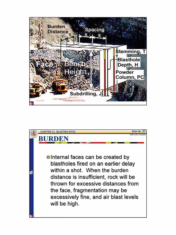
Subdrilling J -
Internal faces can be created by blastholes fired on an earlier delay within a shot When the burden distance is insufficient rock will be thrown for excessive distances from the face fragmentation may be excessively fine and air blast levels will be high
~~ An empirical formula for approximating a burden distance to be used on a first trial shot is
where
B = burden ft SGe = specific gravity of the explosive
SG =specific gravity of the rock
De= diameter of the explosive in
(1)
~Igt The actual diameter will depend on the manufacturers packaging container thickness
~ If the specific product is known the exact information should be used
Rock density is an indicator of strength which in turn governs the amount of energy required to cause breakage
~gt The approximate specific gravities of rocks are given in Table 1 (T13-1 Text)
Table I Density by Nominal Rock Classifications (Table 13- 1 Text) Rock Classification Specific Gravity Density Broken (toncu yd)
Basalt 18 shy 30 236 - 253 Dibase 26-30 219-253 Diorite 28-30 236-253 Dolomite 28 -29 236-244 Gneiss 26 - 29 219 - 244 Uramte 26-29 219-22 Gypsum 23 - 28 194 shy 226 llematite 45-53 379-447 Limestone 24-29 194-228 Marble 2 1-2 9 202 shy 228 Quartzite 20-28 219-236 Sandstone 20-28 185- 236 Shale 24-28 202-236 Slate 25-28 228-236 Trap Rock 26-30 238-253
CD Explosive density is used in Eq 1 because of the proportional relationship between explosive density and strength
c== There are however some explosive emulsions which exhibit differing strengths at equal densities
ct In such a case Eq 1 will not be valid ct An equation based on relative bulk strength
instead of density can be used in such situations
ExamQle 1 orshy we
A contractor plans to use dynamite that has specific gravity of 13 to open an excavation in granite rock The drilling equipment available will drill a 3-in blasthole Dynamite comes packaged in 2 34-in diameter sticks What is the recommended burden distance for the first trial shot
From Table 1 (Table 14-1 Text)
S fiG f G 2middot6+ 2middot9 28pec1 1c rav1ty o ramte = = 2
B = ( 2
SG + 15) D = ( 2
(13) +15) (275) = 67 ft SCT 28
BliLK STRENGTH
~~ Relative bulk strength is the strength ratio for a constant volume compared to a standard explosive such as ANFO
c ANFO ammonium nitrate and fuel oil is the standard explosive with an energyshylevel rating of 100
c The relative bulk strength rating should be based on test data under specified conditions
Texa s City 16 4Pril1947
ANFO is an explosive used extensively on construction projects
BULK STRENGTH
~The burden distance 8 based on relative bulk energy is given by
B~ 067 Dv St (2) SG
SG = specific gravity ofthe rock De= diameter of the explos ive in St = relative bulk strength compared to ANFO
BlJRDEN DISTANCE
c~When one or two rows of blastholes are used the burden distance between rows will usually be equal
c~ If more than two rows are to be fired in a single shot either the burden distance of the rear hales must be adjusted or delay devices must be used to allow the face rock from the front rows to move
BURDEN DISTANCE
~~The burden distance should also be adjusted because of the geological variations
C Rock is not homogeneous material as assumed by all formulas
Therefore it is always necessary to use correction factors for specific geological conditions
STRIKE 1~
BURDEN corrected
K =d bull
BURDEN DISTANCE
~ The corrected burden distance can be computed from the following equation
IE corrected =B X Kd X Ks I (3)
Where
Kd =correction factor for rock deposition
Ks =correction factor for rock structure
Table 2 gives burden distance correction factors for
rock deposition and rock structure
BlJRDEN DISTANCE CORRECTION FACTORS
Table 2 Dens ity by Nom inal Rock Classifications (Table 13-2 Text) Rock Depostion Kd
Bedding steeply dipping into cut Bedding steeply dipping into face
118 095
Other cases ofdepostion 100 Rock Structure Ks
Heavily cracked frequent weak joints weakly cemented layers
130
Thin well-cemented layers with tight joints 110 Massive intact rock 095
Examele 2 we
A new quarry is being opened in a limestone formation having horizontal bedding with numerous weak joints From a borehole test drilling program it is believed that the limestone is highly laminated with many weakly cemented layers Because of possible wet conditions a cartridged slurry (relative bulk density of 140) will be used as explosive The 65-in blastholes will be loaded with 5-in diameter cartridges What is the burden distance
Examp]e 2 (continued) we
From Table 1 (Table 13-1 Text)
For limestone the specific gravity is between 24 and 29
A S fi G 24 + 2middot9 2 9 verage peel JC rav1ty = = 2
B =06703 St =067(5)V140 =1265 ft
SG 26
Kd =1 (horizontal bedding see Table 2)
Ks = 13 (numerous weakly cemented layers Table 2)
Bcorrected =B X Kd X Ks =1265(1)(13) =164 ft
ExamR]e 2 (cotinued) ++e
Table I Density by Nominal Rock Classifications (Table 13shy 1 Text) Rock Classification S pecific G ravity Dens ity Broken (toncu yd)
Basalt 18-30 236-253 Dibase 26-30 219-253 Diorite 28-30 236-253 Dolomite 28-29 236-244 Gneiss 26 29 219 244 Granite 26 - 29 219 - 228 Gvosum 23-28 194-226 Hematite 45 - 53 379 - 447 Limestone 24-29 194-228 Marble 21- 29 202 - 228 Quartzite 20-28 219-236 Sandstone 20 - 28 185 shy 236 Shale 24 -28 202 - 236 Slate 25 -28 228-236 Trap Rock 26 - 30 238 shy 253
STEMMING
c-Definition Stemming is the adding of an inert material such as drill cuttings on top of the explosive in a blasthole for the purpose of confining the energy of the explosive
crTo function property the material used for stemming must lock into the borehole
Subdrilling J -
STEMMING
cbull lt is common practice to use drill cuttings as the stemming material
cr To function properly the stemming material should have an average diameter 005 times the diameter of the hole and should be angular
c~ If the stemming distance is too great there will be poor top breakage from the explosion and backbreak will increase
STEMMING
cbullWhen the stemming distance is inadequate the explosion will escape prematurely from the hole
c~ Under normal conditions properly designed burden and explosive and good stemming material a stemming distance T of 07 times the burden distance B will be satisfactory
IT= 07 X B I (4)
SlJBDRILLING
c A shot will normally not break to the very bottom of the blasthole This can be understood by remembering that the second mechanism of breakage is flexural rupture
~ To achieve a specified grade one will need to drill below the desired floor elevation This portion of the blasthole below the desired final grade is termed subdrilling
SUBDRILLING
CD The subdrilling distance J required can be approximated by the following formula
(5)
cbull Subdrilling represents the depth required for explosive placement not a field drilling depth
SlJBDRILLING
~tOuring the drilling operation there will be random drilling depth errors holes will slough and material will accidentally fall into some holes Therefore for practical reasons drilling should be to a depth slightly greater than that calculated
BLASTHOLE SIZE
n Once again the second mechanism of rupture and the stiffness ratio (SR) need to be considered
cbull The stiffness ratio (SR) for blasting purposes is the bench height (L)
divided by the burden distance (B)
BLASTHOLE SIZE
bull~The size (diameter) of the blasthole will affect blast considerations concerning fragmentation air blast flyrock and ground vibration
~~ The economics of drilling is the second consideration in determining blasthole SIZe
Larger holes are usually more economical to drill but they introduce possible blast problems
lsR ~I (6J
STIFFNESS RATIO bull bull ( bench height )
Stiffness ratio burden distance
affects several critical blasting considerations
bull Fragmentation bull Air blast bull Flyrock bull Ground vibration
STIFFNESS RATIO
The bench height is usually set by physical constrains the existing ground~~~~ elevation and plan grade
STIFFNESS RATIO
In the case of deep cuts it may be possible to adjust the bench ~~ height with stepped cuts
STIFFNESS RATIO The bench height should be matched to the reach of the excavation equipment (optimum height of cut)
BLASTHOLE SIZE
bull~ In some situations as in a quarry the blaster can adapt the bench height to optimize the blast but on a road project the existing ground and the specified final roadway grades set limits on any bench height modification
c The following table (Table 3 Table 13-3 Text) gives the relationship between the stiffness ratio and the critical blasting factors
BLASTHOLE SIZE
Table 3 Stiffness Ratios Effect on Blasting Factors (Table 13-3 Text)
Stiffness Ratio (RS) 1 2 3 gt4
Fragmentation Poor Fair Good Excellmt Air Blast Severe Fair Good Excellmt Fl)Tock Severe Fair Good Excellmt Ground Vibration Severe Fair Good Excellmt Strffness Ratros above 4 yreld no mcrease m bmefit
BLASTHOLE SIZE
c~ One of the parameters in both Eqs 1 and 2 was the diameter of the explosive De The diameter of the explosive is limited by the diameter of the blasthole
B =(2SG+ 15)D SG
c If it is desirable to drill larger blastholes for economic reasons (usually cheaper) the burden distance will be affected
BLASTHOLE SIZE
Explosive diameter and bore hole diameter may not be the same
LINER or FILLER
BORE HOLE
ExamQle 3 or- we
o A contractor plans to use dynamite that has specific gravity of 13 to open an excavation in granite rock The drilling equipment available will drill a 5-in blastones Dynamite comes packaged in 2 75-in and 45-diameter sticks If the specifications call for a 13-ft bench height and the extent of the excavation perpendicular to the face is 100 fthow many rows of blastholes will be required for both the 2 75 and 45-diameter packages Which package of dynamite will result in lesser blasting problems
Examp]e 3 (contd) we
For the 275-in dia package fi G f G 2middot6 + 2middot9 2 8 Spec1 1c rav1ty o ran1te = =
2
2 2 1 3B = ( SG + 15) D = ( lt middot ) + 15) (275 = 6 7ft
SG 28
100 Noof rows required = + I = 1593 ~ 16 rows
67 -shy
For the 45-in dia package
2 2 1 3 B2 = ( sc + t5)n = ( lt middot gt+ t5)lt 45 = 1 o9 ft
SG 28
100 Noof rows required = + I= 1017 ~ IOrows
109 -shy
ExameJe 3 (co_ntd) we
For the 275-in dia explosive package
SR =_pound_ =_2_ =194 I Bl 67 ---shy
For the 45-in dia explosive package
SR = _ =_l_ = 119 B
2 109 -shy
Comparing the results of the stiffness ratios using Table 3 (Table 13-3 Text) the 25-in diameter explosive package has lesser blasting problem
2 3 gt4
Poor Fair Good Excellent
Severe Fair Good Excellent Severe Fair Cood Excellent Severe Fair Good Excellent
Examp]e 3 (contd) we
Table 3 Stiffness Ratios Effect on Blasting Factors (Table 13-3 Text)
Stilfuess Ratios above 4 yield no increase in benefit
ExamQle 4 or- we
Suppose that the rock blasting in Example 3 should be accomplished with a minimum stiffness ratio of 3 what will be the ideal explosive diameter
13 SR=_ =gt B=_= =433
B SR 3
2 2 3B = ( SG + 15) D = ( (l ) + Is)D = 433 ft
S(Jr 28
D~ = 1783 in
ideal explosive diameter= 175 or 134 - diameter
CKECK
2 3B = ( (- ) +15)(1 75) = 425 =gt SR =__ = ~= 306 gt 3 OK
28 B 425
c~ Proper spacing of blastholes is controlled by the initiation timing and the stiffness ratio
~~ When holes are spaced too close and fired instantaneously venting of the energy will occur with resulting air blast and flyrock
C) When the spacing is extended there is a limit beyond which fragmentation will become harsh
Before beginning a spacing analysis two questions must be answered concerning the shot
1 Will the charges be fired instantaneously or will delays be used
2 Is the stiffness ratio greater than 4
SPACING Spacing is controlled by initiation timing and stiffness ratio
(fF Instantaneous initiation SR greater than 1 but less than 4
ru= Instantaneous initiation SR equal to or greater than 4
Text p 388 equations (13-6 and 13-7)
SPACING Spacing is controlled by initiation timing and stiffness ratio
~ Delayed initiation SR greater than 1 but less than 4
f Delayed initiation SR equal to or greater than 4
Text p~ 388 equations (13-8 and 13-9)
ctAn SR of less than 4 is considered a low bench and a high bench is a SR value of 4 or greater This means that there are four cases to be considered
1 Instantaneous initiation with the SR
greater than I but less than 4
where S = spacing is= L +32B I (7)
L =bench height
2 Instantaneous initiation with the SR
equal to or greater than 4
3 Delayed initiation with the SR
greater than I but less than 4
Is L+BI (9)
4 Delayed initiation with the SR
equal to or greater than 4
Is= 14BI (9)
Note The actual spacing utilized in the field should be within 15 plus or minus the calculated value
SPACING Spacing in the field should be within plus or minus 15dego of the calculated value
Calculated spacing
-15oo
middot ExamP-le 5 ---Z
It is proposed to load 4-in diameter blasholes with bulk ANFO The contractor would like to use an 8 X 8 drill pattern Assuming the burden distance is correct will the 8-ft spacing be acceptable The bench height is 35 ft and each hole is to be fired on separate delay
ExamR]e 5 (cotd) we
B =8ft and L
Check the stiffness ratio LIB for high or low bench
Delay timing therefore use Eq 9
s =14(8) =112 ft
Range= 112 plusmn 015(112)
The spacing is not OK should be
= 35 ft
_= 35 = 44ft B 8
S =95 to 129 ft
As a minimum the pattern
8X 95
Example 6
A project in granite rock will have an average bench height of 20 ft An explosive having a specific gravity of 12 has been proposed The contractors equipment can easily drill 3-in diameter holes Assume the packaged diameter of the explosives will be 25 in Delay blasting techniques will be used Develop a blast design for the project
From Table I (Table 13-1 Text)
S fi G fG 2middot6 +2middot9 2pec1 1c rav1ty o rarute = = 75 2
B= ( 2
SG + 15)D= ( 2
(12) + 15) (25) = 593 ft
SG 2 75
ExamR]e 6 (cotd) we
Table l Density by Nominal Rock Classifications (Table 13- l Text) Rock Classification Specific Gravity Density Broken (toncu yd)
Basalt 18-30 236-253 Dibase 26-30 219-253 Diorite 28 - 30 236 -253 Dolomite 28-29 236-244 Gneiss 26 - 29 219 - 244 Granite 26-29 219-228 Gypsum 23-28 194 -226 Hematite 45-53 379-447 Limestone 24-29 194-228 Ma1ble 2 1-29 202 -228 Quartzite 20-28 219 -236 Sandstone 20-28 185- 236 Shale 24 - 28 202 - 236 Slate 25-28 228-236 Trap Rock 26 - 30 238 - 253
Examele 6 (contd) we
Hence use 6 in for the burden distance B
SF=~= 20 =33~good (accordingto Table3)B 6
The stemming depth (T) = 07 x 8 = 07(6) = 42 ft
Use 4ft for the stemming depth T
The subdrilling (J) = 03x B = 03(6) = 18 ft
Use 2 ft for subdrilling depth J
6I lt SR lt 4 and delayed initiation~ S = L+ 78 = 20 + (7)( ) 775 ft 8 8
Range= 775 plusmn 015(775) S = 66 to89 ft
As a first trial use a 6-ft burden X 8-ft spacing pattern
ExamR]e 6 (cotd) we
Table 3 Stiffness Ratios Effect on Blasting Factors (Table 13-3 Text)
Stiffness Ratio (RS) 2 3 gt 4middot Fra entation Poor Fair Good Excellent
Severe Fair Good Severe Fair Good Severe Fair Good
Excellent Excellent Excellent
POWDER COLlIMN AND POWDER FACTOR
aThe amount of explosive required to fracture a cubic yard of rock is a measure of economy of blast design
C)Table 5 (Table 13-4 Text) is a loading density chart which allows the engineer to easily calculate the weight of explosive required for a blasthole
POWDER COLUMN AND POWDER FACTOR
Table 4 Explosive Loading Density Chart in lb per ft ofColumn for a a Given Explosive Specific Gravity (Table 13-4 Text)
c_ lloJ 0~ OM
I 027 031 I 04) U ll 061 069 l j 083 -I(JJ 123 2j 170 192 3 Z4S 276 3j 334 ) 75
4)6 490
bulll 552 621 5 6SI 766 5j 824 927 6 9RI 11(13
6~ 1151 1295 7 1335 IS01 8 1743 1961 9 l1o6 2482
10 l12A 3064
Uplosi~~specific traoity
100 110 110 IJt lAO lst
034 037 041 044 048 OSI USl ~ 064 069 074 010 077 014 092 100 107 lll 104 IIS 125 136 146 156 136 150 163 177 191 2Q4 21) 2)4 Z77 319us 298 306 337 368 398 429 4 17 459 501 52 584 middot~ 626 54S 600 654 )OS 76J 817 689 158 827 896 965 10)4 151 936 1022 1107 1192 1277
1030 1133 IZ36 1))1 1442 15A$ 1226 13 147 1 1593 1716 11139 1439 1582 1726 1870 2014 2151 1668 1115 2002 2169 l336 250) 2179 2397 2615 213) 3051 ~ 2158 )034 3310 JSampS 3861 4IJ7 3405 3746 4016 4426 4767 5101
POWDER COLUMN
Powder column length is the blasthole depth minus the stemming depth
Blasthole depth =
bench height+ subdrilling
Powder column =
blasthole depth - stemming
POWDER COLlJMN AND POWDER FACTOR
= Definition The powder factor is the ratio of the total weight (lb)of explosive in powder column length to the total volume (cu yd) of rock fractured by one blasthole under the pattern area to a depth of bench depth equal L that is
P d Fow er actor =
POWDER COLUMN AND POWDER FACTOR
~Definition
The powder column length is the total hole length less stemming that is
Powder Length = L + J - T I (10)
Total Weight (lb) of Powder Column Length (11)
Total Volume under Pattern Area(cu yd)
Examele 7 we
For Example 6 calculate the powder column length the total weight of explosive used per blasthole and the powder factor From Example 6 L = 20 ft J = 4 ft and T = 4 ft Pattern = 6 X 8
Specific Gravity of Explosive = 12 Explosive diameter = 25
From Table 4 (Table 14-4 Text) Loading Density = 255 lb per ft
Powder Column Length =(L+J)-T = 20+ 2-4 = 18ft
The Total Weight of Explosive per Column = 18x 235= 4591b
Total Weight of Explosive per Hole- shyPowder Factor=
Volume of Rock Fractured under Pattern Area
6 8 20 = 459- ( ) = 1291bcu yd
27 shy
POWDER COLlIMN AND POWDER FACTOR
~ In all the examples presented so far it has been assumed that only one explosive was used in a blasthole
e If a hole is loaded with ANFO it will require a primer to initiate the explosion
e For example in the case of a powder column that is 18 ft and that will be loaded with ANFO (G8 =08) a primer will have to be placed at the bottom of the hole
POWDER COLUMN AND POWDER FACTOR
e A stick dynamite (G8 =13) will require a minimum of 8 in (0667 ft) Therefore there will be 208 in (1733 ft) of ANFO and 8 in (067 ft) of dynamite
~ The weight of explosives based on a 25-in explosive diameter will be
170 lbft X 1733 ft = 2946 lb
277 lbft X 067 ft = 185 lb
3131 lb
The total per hole is 3131 lb for 18 ft of powder column
MATERIAL HANDLING CONSIDERATIONS
~~ The economics of handling the fractured rock is a factor which should be considered in blast design
e Aithough it is critical to achieve good breakage the blast pattern will affect such considerations as the type of equipment and the bucket fill factor
c~ The appropriate piling of the blasted rock by the shot is dependent on the blast design
MATERIAL HANDLING CONSIDERATIONS
c To utilize the blast to accomplish good breakage and appropriate piling one should apply the following principles 1 Rock movement will be parallel to the burden
dimension
21nstantaneous initiation along a row causes more displacement than delayed initiation
3 Shots delayed row tyen rrJN scatter the rock more than shots fired in a V pattern
4 Shots designed in a V pttern firing sequence give maximum piling close to the face
MATERIAL HANDLING CONSIDERATIONS
w~a --f_ltbull-01~-a~~_~~-c~
PRESPLITTING ROCK
c~ Presplitting Rock is a technique of drilling and blasting which breaks rock along a relatively smooth surface (see next figure)
~~ The holes usually are 29 to 3 in in diameter and are drilled along the desired surface at spacings varying from 18 to 36 in depending on the characteristic of the rock
PRESPLITTING ROCK
c~The holes are loaded with one or two sticks of dynamite at the bottoms with smaller charges such as 125 x 4- in sticks spaced at 12-in intervals to the top of the portion of the holes to be loaded
PRESPLITTING ROCK
o It is important that the charges be less than half the blasthole diameter and they should not touch the walls of the holes
ca The appropriate load of explosive per foot of presplit blasthole is given by
~ (12)
where dec =explosive load lb per ft Dh =diameter of blasthole in
PRESPLITTING ROCK c When the formula given by Eq 12 is used to
arrive at an explosive loading the spacing between blastholes can be determined by the following equation
Is --p_=_l OD----hI_ (13)
where sp = presplit blasthole spacing in
~ Presplit blastholes are not extended below grade In the bottom of the hole a concentrated charge of 2 to 3 times dec should be placed instead of subdrilling
ExamP-le 8 ---Z
By contract specification the walls of a highway excavation through rock must be presplit The contractor will be using drilling equipment capable of drilling a 3-in hole What explosive load and hole spacing should he try for the first presplit shot on the project
d = D = (3) 2
= 032~ ec 28 28 ft
Sp =lODh =10(3) =30 in
The bottom load should be 3 x 032 = 096lb
SAFETY CONSIDERATIONS
~~An accident involving explosives may easily kill or cause serious injury
~DThe prevention of such accidents depends on careful planning and faithful observation of proper blasting practices
c~There are federal and state regulations concerning the transportation and handling of explosives
SAFETY CONSIDERATIONS
c~ Safety information on specific products is provided by the manufacturer
c~ In addition to regulations and product information there are recommended practices such as the evacuation of the blast area during the approach of an electrical storm whether electric or nonelectric initiation systems are used
SAFETY CONSIDERATIONS
~A good source for material on recommended blasting safety practices is the Institute of Makers of Explosives in New York City
e Misfire In shooting charges of explosives one or more charges may fail to explode This is referred to as a misfire
~ It is necessary to dispose of this explosive before excavating the loosened rock
c The most satisfactory method is to shoot it if possible
FACTORS AFFECTING VIBRATION
Some of the critical factors that should be considered are 1 Burden 10 Rock Type 2 Spacing 11 Rock Physical Properties 3 Subdrilling 12 Geological Features 4 Stemming Depth 13 Number ofHoles in a Row 5 Type ofStemming 14 Number ofRows 6 Bench Height 15 Row-to-Row Delays 7 Number of Decks 16 Initiator Precision 8 Charge Geometry 17 Face Angle to Structure 9 Powder Column Length 18 Explosive Energy
SPACING dont forget-shySAFETY
FACTORS AFFECTING VIBRATION
The US Bureau of Mines has proposed a formula to evaluate vibration and as a way to control blasting operation as follows
[Lgt = ~[ (14)
where Ds = scaled distance (nondimensional factor)
d = distance from shot to structure ft
W= maximum charge weight per delay lb
o A scale value of 50 or greater indicates that a shot is safe with respect to vibration
e Some regulatory agencies require a value of 60 or greater
VIBRATION
Check vibration by formula 13-12 and adjust amount of explosive per delay if necessary
Text p 397
FIRE IN THE HOLE
- barcode 550567
- barcodetext SDMS Doc ID 550567

BURDEN DISTANCE
~ The corrected burden distance can be computed from the following equation
IE corrected =B X Kd X Ks I (3)
Where
Kd =correction factor for rock deposition
Ks =correction factor for rock structure
Table 2 gives burden distance correction factors for
rock deposition and rock structure
BlJRDEN DISTANCE CORRECTION FACTORS
Table 2 Dens ity by Nom inal Rock Classifications (Table 13-2 Text) Rock Depostion Kd
Bedding steeply dipping into cut Bedding steeply dipping into face
118 095
Other cases ofdepostion 100 Rock Structure Ks
Heavily cracked frequent weak joints weakly cemented layers
130
Thin well-cemented layers with tight joints 110 Massive intact rock 095
Examele 2 we
A new quarry is being opened in a limestone formation having horizontal bedding with numerous weak joints From a borehole test drilling program it is believed that the limestone is highly laminated with many weakly cemented layers Because of possible wet conditions a cartridged slurry (relative bulk density of 140) will be used as explosive The 65-in blastholes will be loaded with 5-in diameter cartridges What is the burden distance
Examp]e 2 (continued) we
From Table 1 (Table 13-1 Text)
For limestone the specific gravity is between 24 and 29
A S fi G 24 + 2middot9 2 9 verage peel JC rav1ty = = 2
B =06703 St =067(5)V140 =1265 ft
SG 26
Kd =1 (horizontal bedding see Table 2)
Ks = 13 (numerous weakly cemented layers Table 2)
Bcorrected =B X Kd X Ks =1265(1)(13) =164 ft
ExamR]e 2 (cotinued) ++e
Table I Density by Nominal Rock Classifications (Table 13shy 1 Text) Rock Classification S pecific G ravity Dens ity Broken (toncu yd)
Basalt 18-30 236-253 Dibase 26-30 219-253 Diorite 28-30 236-253 Dolomite 28-29 236-244 Gneiss 26 29 219 244 Granite 26 - 29 219 - 228 Gvosum 23-28 194-226 Hematite 45 - 53 379 - 447 Limestone 24-29 194-228 Marble 21- 29 202 - 228 Quartzite 20-28 219-236 Sandstone 20 - 28 185 shy 236 Shale 24 -28 202 - 236 Slate 25 -28 228-236 Trap Rock 26 - 30 238 shy 253
STEMMING
c-Definition Stemming is the adding of an inert material such as drill cuttings on top of the explosive in a blasthole for the purpose of confining the energy of the explosive
crTo function property the material used for stemming must lock into the borehole
Subdrilling J -
STEMMING
cbull lt is common practice to use drill cuttings as the stemming material
cr To function properly the stemming material should have an average diameter 005 times the diameter of the hole and should be angular
c~ If the stemming distance is too great there will be poor top breakage from the explosion and backbreak will increase
STEMMING
cbullWhen the stemming distance is inadequate the explosion will escape prematurely from the hole
c~ Under normal conditions properly designed burden and explosive and good stemming material a stemming distance T of 07 times the burden distance B will be satisfactory
IT= 07 X B I (4)
SlJBDRILLING
c A shot will normally not break to the very bottom of the blasthole This can be understood by remembering that the second mechanism of breakage is flexural rupture
~ To achieve a specified grade one will need to drill below the desired floor elevation This portion of the blasthole below the desired final grade is termed subdrilling
SUBDRILLING
CD The subdrilling distance J required can be approximated by the following formula
(5)
cbull Subdrilling represents the depth required for explosive placement not a field drilling depth
SlJBDRILLING
~tOuring the drilling operation there will be random drilling depth errors holes will slough and material will accidentally fall into some holes Therefore for practical reasons drilling should be to a depth slightly greater than that calculated
BLASTHOLE SIZE
n Once again the second mechanism of rupture and the stiffness ratio (SR) need to be considered
cbull The stiffness ratio (SR) for blasting purposes is the bench height (L)
divided by the burden distance (B)
BLASTHOLE SIZE
bull~The size (diameter) of the blasthole will affect blast considerations concerning fragmentation air blast flyrock and ground vibration
~~ The economics of drilling is the second consideration in determining blasthole SIZe
Larger holes are usually more economical to drill but they introduce possible blast problems
lsR ~I (6J
STIFFNESS RATIO bull bull ( bench height )
Stiffness ratio burden distance
affects several critical blasting considerations
bull Fragmentation bull Air blast bull Flyrock bull Ground vibration
STIFFNESS RATIO
The bench height is usually set by physical constrains the existing ground~~~~ elevation and plan grade
STIFFNESS RATIO
In the case of deep cuts it may be possible to adjust the bench ~~ height with stepped cuts
STIFFNESS RATIO The bench height should be matched to the reach of the excavation equipment (optimum height of cut)
BLASTHOLE SIZE
bull~ In some situations as in a quarry the blaster can adapt the bench height to optimize the blast but on a road project the existing ground and the specified final roadway grades set limits on any bench height modification
c The following table (Table 3 Table 13-3 Text) gives the relationship between the stiffness ratio and the critical blasting factors
BLASTHOLE SIZE
Table 3 Stiffness Ratios Effect on Blasting Factors (Table 13-3 Text)
Stiffness Ratio (RS) 1 2 3 gt4
Fragmentation Poor Fair Good Excellmt Air Blast Severe Fair Good Excellmt Fl)Tock Severe Fair Good Excellmt Ground Vibration Severe Fair Good Excellmt Strffness Ratros above 4 yreld no mcrease m bmefit
BLASTHOLE SIZE
c~ One of the parameters in both Eqs 1 and 2 was the diameter of the explosive De The diameter of the explosive is limited by the diameter of the blasthole
B =(2SG+ 15)D SG
c If it is desirable to drill larger blastholes for economic reasons (usually cheaper) the burden distance will be affected
BLASTHOLE SIZE
Explosive diameter and bore hole diameter may not be the same
LINER or FILLER
BORE HOLE
ExamQle 3 or- we
o A contractor plans to use dynamite that has specific gravity of 13 to open an excavation in granite rock The drilling equipment available will drill a 5-in blastones Dynamite comes packaged in 2 75-in and 45-diameter sticks If the specifications call for a 13-ft bench height and the extent of the excavation perpendicular to the face is 100 fthow many rows of blastholes will be required for both the 2 75 and 45-diameter packages Which package of dynamite will result in lesser blasting problems
Examp]e 3 (contd) we
For the 275-in dia package fi G f G 2middot6 + 2middot9 2 8 Spec1 1c rav1ty o ran1te = =
2
2 2 1 3B = ( SG + 15) D = ( lt middot ) + 15) (275 = 6 7ft
SG 28
100 Noof rows required = + I = 1593 ~ 16 rows
67 -shy
For the 45-in dia package
2 2 1 3 B2 = ( sc + t5)n = ( lt middot gt+ t5)lt 45 = 1 o9 ft
SG 28
100 Noof rows required = + I= 1017 ~ IOrows
109 -shy
ExameJe 3 (co_ntd) we
For the 275-in dia explosive package
SR =_pound_ =_2_ =194 I Bl 67 ---shy
For the 45-in dia explosive package
SR = _ =_l_ = 119 B
2 109 -shy
Comparing the results of the stiffness ratios using Table 3 (Table 13-3 Text) the 25-in diameter explosive package has lesser blasting problem
2 3 gt4
Poor Fair Good Excellent
Severe Fair Good Excellent Severe Fair Cood Excellent Severe Fair Good Excellent
Examp]e 3 (contd) we
Table 3 Stiffness Ratios Effect on Blasting Factors (Table 13-3 Text)
Stilfuess Ratios above 4 yield no increase in benefit
ExamQle 4 or- we
Suppose that the rock blasting in Example 3 should be accomplished with a minimum stiffness ratio of 3 what will be the ideal explosive diameter
13 SR=_ =gt B=_= =433
B SR 3
2 2 3B = ( SG + 15) D = ( (l ) + Is)D = 433 ft
S(Jr 28
D~ = 1783 in
ideal explosive diameter= 175 or 134 - diameter
CKECK
2 3B = ( (- ) +15)(1 75) = 425 =gt SR =__ = ~= 306 gt 3 OK
28 B 425
c~ Proper spacing of blastholes is controlled by the initiation timing and the stiffness ratio
~~ When holes are spaced too close and fired instantaneously venting of the energy will occur with resulting air blast and flyrock
C) When the spacing is extended there is a limit beyond which fragmentation will become harsh
Before beginning a spacing analysis two questions must be answered concerning the shot
1 Will the charges be fired instantaneously or will delays be used
2 Is the stiffness ratio greater than 4
SPACING Spacing is controlled by initiation timing and stiffness ratio
(fF Instantaneous initiation SR greater than 1 but less than 4
ru= Instantaneous initiation SR equal to or greater than 4
Text p 388 equations (13-6 and 13-7)
SPACING Spacing is controlled by initiation timing and stiffness ratio
~ Delayed initiation SR greater than 1 but less than 4
f Delayed initiation SR equal to or greater than 4
Text p~ 388 equations (13-8 and 13-9)
ctAn SR of less than 4 is considered a low bench and a high bench is a SR value of 4 or greater This means that there are four cases to be considered
1 Instantaneous initiation with the SR
greater than I but less than 4
where S = spacing is= L +32B I (7)
L =bench height
2 Instantaneous initiation with the SR
equal to or greater than 4
3 Delayed initiation with the SR
greater than I but less than 4
Is L+BI (9)
4 Delayed initiation with the SR
equal to or greater than 4
Is= 14BI (9)
Note The actual spacing utilized in the field should be within 15 plus or minus the calculated value
SPACING Spacing in the field should be within plus or minus 15dego of the calculated value
Calculated spacing
-15oo
middot ExamP-le 5 ---Z
It is proposed to load 4-in diameter blasholes with bulk ANFO The contractor would like to use an 8 X 8 drill pattern Assuming the burden distance is correct will the 8-ft spacing be acceptable The bench height is 35 ft and each hole is to be fired on separate delay
ExamR]e 5 (cotd) we
B =8ft and L
Check the stiffness ratio LIB for high or low bench
Delay timing therefore use Eq 9
s =14(8) =112 ft
Range= 112 plusmn 015(112)
The spacing is not OK should be
= 35 ft
_= 35 = 44ft B 8
S =95 to 129 ft
As a minimum the pattern
8X 95
Example 6
A project in granite rock will have an average bench height of 20 ft An explosive having a specific gravity of 12 has been proposed The contractors equipment can easily drill 3-in diameter holes Assume the packaged diameter of the explosives will be 25 in Delay blasting techniques will be used Develop a blast design for the project
From Table I (Table 13-1 Text)
S fi G fG 2middot6 +2middot9 2pec1 1c rav1ty o rarute = = 75 2
B= ( 2
SG + 15)D= ( 2
(12) + 15) (25) = 593 ft
SG 2 75
ExamR]e 6 (cotd) we
Table l Density by Nominal Rock Classifications (Table 13- l Text) Rock Classification Specific Gravity Density Broken (toncu yd)
Basalt 18-30 236-253 Dibase 26-30 219-253 Diorite 28 - 30 236 -253 Dolomite 28-29 236-244 Gneiss 26 - 29 219 - 244 Granite 26-29 219-228 Gypsum 23-28 194 -226 Hematite 45-53 379-447 Limestone 24-29 194-228 Ma1ble 2 1-29 202 -228 Quartzite 20-28 219 -236 Sandstone 20-28 185- 236 Shale 24 - 28 202 - 236 Slate 25-28 228-236 Trap Rock 26 - 30 238 - 253
Examele 6 (contd) we
Hence use 6 in for the burden distance B
SF=~= 20 =33~good (accordingto Table3)B 6
The stemming depth (T) = 07 x 8 = 07(6) = 42 ft
Use 4ft for the stemming depth T
The subdrilling (J) = 03x B = 03(6) = 18 ft
Use 2 ft for subdrilling depth J
6I lt SR lt 4 and delayed initiation~ S = L+ 78 = 20 + (7)( ) 775 ft 8 8
Range= 775 plusmn 015(775) S = 66 to89 ft
As a first trial use a 6-ft burden X 8-ft spacing pattern
ExamR]e 6 (cotd) we
Table 3 Stiffness Ratios Effect on Blasting Factors (Table 13-3 Text)
Stiffness Ratio (RS) 2 3 gt 4middot Fra entation Poor Fair Good Excellent
Severe Fair Good Severe Fair Good Severe Fair Good
Excellent Excellent Excellent
POWDER COLlIMN AND POWDER FACTOR
aThe amount of explosive required to fracture a cubic yard of rock is a measure of economy of blast design
C)Table 5 (Table 13-4 Text) is a loading density chart which allows the engineer to easily calculate the weight of explosive required for a blasthole
POWDER COLUMN AND POWDER FACTOR
Table 4 Explosive Loading Density Chart in lb per ft ofColumn for a a Given Explosive Specific Gravity (Table 13-4 Text)
c_ lloJ 0~ OM
I 027 031 I 04) U ll 061 069 l j 083 -I(JJ 123 2j 170 192 3 Z4S 276 3j 334 ) 75
4)6 490
bulll 552 621 5 6SI 766 5j 824 927 6 9RI 11(13
6~ 1151 1295 7 1335 IS01 8 1743 1961 9 l1o6 2482
10 l12A 3064
Uplosi~~specific traoity
100 110 110 IJt lAO lst
034 037 041 044 048 OSI USl ~ 064 069 074 010 077 014 092 100 107 lll 104 IIS 125 136 146 156 136 150 163 177 191 2Q4 21) 2)4 Z77 319us 298 306 337 368 398 429 4 17 459 501 52 584 middot~ 626 54S 600 654 )OS 76J 817 689 158 827 896 965 10)4 151 936 1022 1107 1192 1277
1030 1133 IZ36 1))1 1442 15A$ 1226 13 147 1 1593 1716 11139 1439 1582 1726 1870 2014 2151 1668 1115 2002 2169 l336 250) 2179 2397 2615 213) 3051 ~ 2158 )034 3310 JSampS 3861 4IJ7 3405 3746 4016 4426 4767 5101
POWDER COLUMN
Powder column length is the blasthole depth minus the stemming depth
Blasthole depth =
bench height+ subdrilling
Powder column =
blasthole depth - stemming
POWDER COLlJMN AND POWDER FACTOR
= Definition The powder factor is the ratio of the total weight (lb)of explosive in powder column length to the total volume (cu yd) of rock fractured by one blasthole under the pattern area to a depth of bench depth equal L that is
P d Fow er actor =
POWDER COLUMN AND POWDER FACTOR
~Definition
The powder column length is the total hole length less stemming that is
Powder Length = L + J - T I (10)
Total Weight (lb) of Powder Column Length (11)
Total Volume under Pattern Area(cu yd)
Examele 7 we
For Example 6 calculate the powder column length the total weight of explosive used per blasthole and the powder factor From Example 6 L = 20 ft J = 4 ft and T = 4 ft Pattern = 6 X 8
Specific Gravity of Explosive = 12 Explosive diameter = 25
From Table 4 (Table 14-4 Text) Loading Density = 255 lb per ft
Powder Column Length =(L+J)-T = 20+ 2-4 = 18ft
The Total Weight of Explosive per Column = 18x 235= 4591b
Total Weight of Explosive per Hole- shyPowder Factor=
Volume of Rock Fractured under Pattern Area
6 8 20 = 459- ( ) = 1291bcu yd
27 shy
POWDER COLlIMN AND POWDER FACTOR
~ In all the examples presented so far it has been assumed that only one explosive was used in a blasthole
e If a hole is loaded with ANFO it will require a primer to initiate the explosion
e For example in the case of a powder column that is 18 ft and that will be loaded with ANFO (G8 =08) a primer will have to be placed at the bottom of the hole
POWDER COLUMN AND POWDER FACTOR
e A stick dynamite (G8 =13) will require a minimum of 8 in (0667 ft) Therefore there will be 208 in (1733 ft) of ANFO and 8 in (067 ft) of dynamite
~ The weight of explosives based on a 25-in explosive diameter will be
170 lbft X 1733 ft = 2946 lb
277 lbft X 067 ft = 185 lb
3131 lb
The total per hole is 3131 lb for 18 ft of powder column
MATERIAL HANDLING CONSIDERATIONS
~~ The economics of handling the fractured rock is a factor which should be considered in blast design
e Aithough it is critical to achieve good breakage the blast pattern will affect such considerations as the type of equipment and the bucket fill factor
c~ The appropriate piling of the blasted rock by the shot is dependent on the blast design
MATERIAL HANDLING CONSIDERATIONS
c To utilize the blast to accomplish good breakage and appropriate piling one should apply the following principles 1 Rock movement will be parallel to the burden
dimension
21nstantaneous initiation along a row causes more displacement than delayed initiation
3 Shots delayed row tyen rrJN scatter the rock more than shots fired in a V pattern
4 Shots designed in a V pttern firing sequence give maximum piling close to the face
MATERIAL HANDLING CONSIDERATIONS
w~a --f_ltbull-01~-a~~_~~-c~
PRESPLITTING ROCK
c~ Presplitting Rock is a technique of drilling and blasting which breaks rock along a relatively smooth surface (see next figure)
~~ The holes usually are 29 to 3 in in diameter and are drilled along the desired surface at spacings varying from 18 to 36 in depending on the characteristic of the rock
PRESPLITTING ROCK
c~The holes are loaded with one or two sticks of dynamite at the bottoms with smaller charges such as 125 x 4- in sticks spaced at 12-in intervals to the top of the portion of the holes to be loaded
PRESPLITTING ROCK
o It is important that the charges be less than half the blasthole diameter and they should not touch the walls of the holes
ca The appropriate load of explosive per foot of presplit blasthole is given by
~ (12)
where dec =explosive load lb per ft Dh =diameter of blasthole in
PRESPLITTING ROCK c When the formula given by Eq 12 is used to
arrive at an explosive loading the spacing between blastholes can be determined by the following equation
Is --p_=_l OD----hI_ (13)
where sp = presplit blasthole spacing in
~ Presplit blastholes are not extended below grade In the bottom of the hole a concentrated charge of 2 to 3 times dec should be placed instead of subdrilling
ExamP-le 8 ---Z
By contract specification the walls of a highway excavation through rock must be presplit The contractor will be using drilling equipment capable of drilling a 3-in hole What explosive load and hole spacing should he try for the first presplit shot on the project
d = D = (3) 2
= 032~ ec 28 28 ft
Sp =lODh =10(3) =30 in
The bottom load should be 3 x 032 = 096lb
SAFETY CONSIDERATIONS
~~An accident involving explosives may easily kill or cause serious injury
~DThe prevention of such accidents depends on careful planning and faithful observation of proper blasting practices
c~There are federal and state regulations concerning the transportation and handling of explosives
SAFETY CONSIDERATIONS
c~ Safety information on specific products is provided by the manufacturer
c~ In addition to regulations and product information there are recommended practices such as the evacuation of the blast area during the approach of an electrical storm whether electric or nonelectric initiation systems are used
SAFETY CONSIDERATIONS
~A good source for material on recommended blasting safety practices is the Institute of Makers of Explosives in New York City
e Misfire In shooting charges of explosives one or more charges may fail to explode This is referred to as a misfire
~ It is necessary to dispose of this explosive before excavating the loosened rock
c The most satisfactory method is to shoot it if possible
FACTORS AFFECTING VIBRATION
Some of the critical factors that should be considered are 1 Burden 10 Rock Type 2 Spacing 11 Rock Physical Properties 3 Subdrilling 12 Geological Features 4 Stemming Depth 13 Number ofHoles in a Row 5 Type ofStemming 14 Number ofRows 6 Bench Height 15 Row-to-Row Delays 7 Number of Decks 16 Initiator Precision 8 Charge Geometry 17 Face Angle to Structure 9 Powder Column Length 18 Explosive Energy
SPACING dont forget-shySAFETY
FACTORS AFFECTING VIBRATION
The US Bureau of Mines has proposed a formula to evaluate vibration and as a way to control blasting operation as follows
[Lgt = ~[ (14)
where Ds = scaled distance (nondimensional factor)
d = distance from shot to structure ft
W= maximum charge weight per delay lb
o A scale value of 50 or greater indicates that a shot is safe with respect to vibration
e Some regulatory agencies require a value of 60 or greater
VIBRATION
Check vibration by formula 13-12 and adjust amount of explosive per delay if necessary
Text p 397
FIRE IN THE HOLE
- barcode 550567
- barcodetext SDMS Doc ID 550567
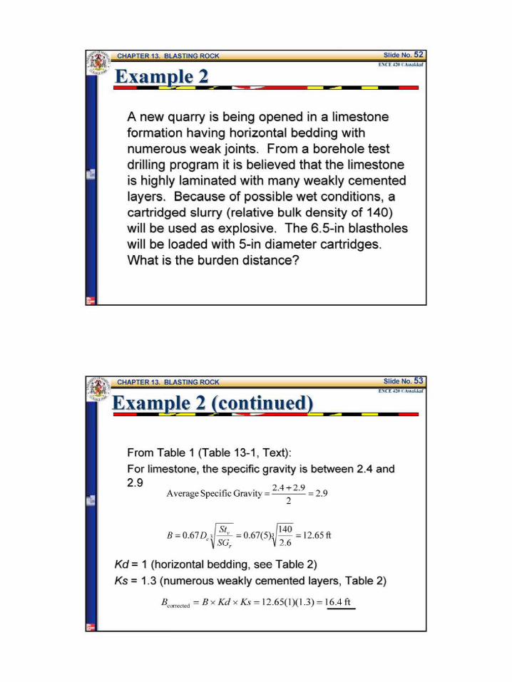

BLASTHOLE SIZE
n Once again the second mechanism of rupture and the stiffness ratio (SR) need to be considered
cbull The stiffness ratio (SR) for blasting purposes is the bench height (L)
divided by the burden distance (B)
BLASTHOLE SIZE
bull~The size (diameter) of the blasthole will affect blast considerations concerning fragmentation air blast flyrock and ground vibration
~~ The economics of drilling is the second consideration in determining blasthole SIZe
Larger holes are usually more economical to drill but they introduce possible blast problems
lsR ~I (6J
STIFFNESS RATIO bull bull ( bench height )
Stiffness ratio burden distance
affects several critical blasting considerations
bull Fragmentation bull Air blast bull Flyrock bull Ground vibration
STIFFNESS RATIO
The bench height is usually set by physical constrains the existing ground~~~~ elevation and plan grade
STIFFNESS RATIO
In the case of deep cuts it may be possible to adjust the bench ~~ height with stepped cuts
STIFFNESS RATIO The bench height should be matched to the reach of the excavation equipment (optimum height of cut)
BLASTHOLE SIZE
bull~ In some situations as in a quarry the blaster can adapt the bench height to optimize the blast but on a road project the existing ground and the specified final roadway grades set limits on any bench height modification
c The following table (Table 3 Table 13-3 Text) gives the relationship between the stiffness ratio and the critical blasting factors
BLASTHOLE SIZE
Table 3 Stiffness Ratios Effect on Blasting Factors (Table 13-3 Text)
Stiffness Ratio (RS) 1 2 3 gt4
Fragmentation Poor Fair Good Excellmt Air Blast Severe Fair Good Excellmt Fl)Tock Severe Fair Good Excellmt Ground Vibration Severe Fair Good Excellmt Strffness Ratros above 4 yreld no mcrease m bmefit
BLASTHOLE SIZE
c~ One of the parameters in both Eqs 1 and 2 was the diameter of the explosive De The diameter of the explosive is limited by the diameter of the blasthole
B =(2SG+ 15)D SG
c If it is desirable to drill larger blastholes for economic reasons (usually cheaper) the burden distance will be affected
BLASTHOLE SIZE
Explosive diameter and bore hole diameter may not be the same
LINER or FILLER
BORE HOLE
ExamQle 3 or- we
o A contractor plans to use dynamite that has specific gravity of 13 to open an excavation in granite rock The drilling equipment available will drill a 5-in blastones Dynamite comes packaged in 2 75-in and 45-diameter sticks If the specifications call for a 13-ft bench height and the extent of the excavation perpendicular to the face is 100 fthow many rows of blastholes will be required for both the 2 75 and 45-diameter packages Which package of dynamite will result in lesser blasting problems
Examp]e 3 (contd) we
For the 275-in dia package fi G f G 2middot6 + 2middot9 2 8 Spec1 1c rav1ty o ran1te = =
2
2 2 1 3B = ( SG + 15) D = ( lt middot ) + 15) (275 = 6 7ft
SG 28
100 Noof rows required = + I = 1593 ~ 16 rows
67 -shy
For the 45-in dia package
2 2 1 3 B2 = ( sc + t5)n = ( lt middot gt+ t5)lt 45 = 1 o9 ft
SG 28
100 Noof rows required = + I= 1017 ~ IOrows
109 -shy
ExameJe 3 (co_ntd) we
For the 275-in dia explosive package
SR =_pound_ =_2_ =194 I Bl 67 ---shy
For the 45-in dia explosive package
SR = _ =_l_ = 119 B
2 109 -shy
Comparing the results of the stiffness ratios using Table 3 (Table 13-3 Text) the 25-in diameter explosive package has lesser blasting problem
2 3 gt4
Poor Fair Good Excellent
Severe Fair Good Excellent Severe Fair Cood Excellent Severe Fair Good Excellent
Examp]e 3 (contd) we
Table 3 Stiffness Ratios Effect on Blasting Factors (Table 13-3 Text)
Stilfuess Ratios above 4 yield no increase in benefit
ExamQle 4 or- we
Suppose that the rock blasting in Example 3 should be accomplished with a minimum stiffness ratio of 3 what will be the ideal explosive diameter
13 SR=_ =gt B=_= =433
B SR 3
2 2 3B = ( SG + 15) D = ( (l ) + Is)D = 433 ft
S(Jr 28
D~ = 1783 in
ideal explosive diameter= 175 or 134 - diameter
CKECK
2 3B = ( (- ) +15)(1 75) = 425 =gt SR =__ = ~= 306 gt 3 OK
28 B 425
c~ Proper spacing of blastholes is controlled by the initiation timing and the stiffness ratio
~~ When holes are spaced too close and fired instantaneously venting of the energy will occur with resulting air blast and flyrock
C) When the spacing is extended there is a limit beyond which fragmentation will become harsh
Before beginning a spacing analysis two questions must be answered concerning the shot
1 Will the charges be fired instantaneously or will delays be used
2 Is the stiffness ratio greater than 4
SPACING Spacing is controlled by initiation timing and stiffness ratio
(fF Instantaneous initiation SR greater than 1 but less than 4
ru= Instantaneous initiation SR equal to or greater than 4
Text p 388 equations (13-6 and 13-7)
SPACING Spacing is controlled by initiation timing and stiffness ratio
~ Delayed initiation SR greater than 1 but less than 4
f Delayed initiation SR equal to or greater than 4
Text p~ 388 equations (13-8 and 13-9)
ctAn SR of less than 4 is considered a low bench and a high bench is a SR value of 4 or greater This means that there are four cases to be considered
1 Instantaneous initiation with the SR
greater than I but less than 4
where S = spacing is= L +32B I (7)
L =bench height
2 Instantaneous initiation with the SR
equal to or greater than 4
3 Delayed initiation with the SR
greater than I but less than 4
Is L+BI (9)
4 Delayed initiation with the SR
equal to or greater than 4
Is= 14BI (9)
Note The actual spacing utilized in the field should be within 15 plus or minus the calculated value
SPACING Spacing in the field should be within plus or minus 15dego of the calculated value
Calculated spacing
-15oo
middot ExamP-le 5 ---Z
It is proposed to load 4-in diameter blasholes with bulk ANFO The contractor would like to use an 8 X 8 drill pattern Assuming the burden distance is correct will the 8-ft spacing be acceptable The bench height is 35 ft and each hole is to be fired on separate delay
ExamR]e 5 (cotd) we
B =8ft and L
Check the stiffness ratio LIB for high or low bench
Delay timing therefore use Eq 9
s =14(8) =112 ft
Range= 112 plusmn 015(112)
The spacing is not OK should be
= 35 ft
_= 35 = 44ft B 8
S =95 to 129 ft
As a minimum the pattern
8X 95
Example 6
A project in granite rock will have an average bench height of 20 ft An explosive having a specific gravity of 12 has been proposed The contractors equipment can easily drill 3-in diameter holes Assume the packaged diameter of the explosives will be 25 in Delay blasting techniques will be used Develop a blast design for the project
From Table I (Table 13-1 Text)
S fi G fG 2middot6 +2middot9 2pec1 1c rav1ty o rarute = = 75 2
B= ( 2
SG + 15)D= ( 2
(12) + 15) (25) = 593 ft
SG 2 75
ExamR]e 6 (cotd) we
Table l Density by Nominal Rock Classifications (Table 13- l Text) Rock Classification Specific Gravity Density Broken (toncu yd)
Basalt 18-30 236-253 Dibase 26-30 219-253 Diorite 28 - 30 236 -253 Dolomite 28-29 236-244 Gneiss 26 - 29 219 - 244 Granite 26-29 219-228 Gypsum 23-28 194 -226 Hematite 45-53 379-447 Limestone 24-29 194-228 Ma1ble 2 1-29 202 -228 Quartzite 20-28 219 -236 Sandstone 20-28 185- 236 Shale 24 - 28 202 - 236 Slate 25-28 228-236 Trap Rock 26 - 30 238 - 253
Examele 6 (contd) we
Hence use 6 in for the burden distance B
SF=~= 20 =33~good (accordingto Table3)B 6
The stemming depth (T) = 07 x 8 = 07(6) = 42 ft
Use 4ft for the stemming depth T
The subdrilling (J) = 03x B = 03(6) = 18 ft
Use 2 ft for subdrilling depth J
6I lt SR lt 4 and delayed initiation~ S = L+ 78 = 20 + (7)( ) 775 ft 8 8
Range= 775 plusmn 015(775) S = 66 to89 ft
As a first trial use a 6-ft burden X 8-ft spacing pattern
ExamR]e 6 (cotd) we
Table 3 Stiffness Ratios Effect on Blasting Factors (Table 13-3 Text)
Stiffness Ratio (RS) 2 3 gt 4middot Fra entation Poor Fair Good Excellent
Severe Fair Good Severe Fair Good Severe Fair Good
Excellent Excellent Excellent
POWDER COLlIMN AND POWDER FACTOR
aThe amount of explosive required to fracture a cubic yard of rock is a measure of economy of blast design
C)Table 5 (Table 13-4 Text) is a loading density chart which allows the engineer to easily calculate the weight of explosive required for a blasthole
POWDER COLUMN AND POWDER FACTOR
Table 4 Explosive Loading Density Chart in lb per ft ofColumn for a a Given Explosive Specific Gravity (Table 13-4 Text)
c_ lloJ 0~ OM
I 027 031 I 04) U ll 061 069 l j 083 -I(JJ 123 2j 170 192 3 Z4S 276 3j 334 ) 75
4)6 490
bulll 552 621 5 6SI 766 5j 824 927 6 9RI 11(13
6~ 1151 1295 7 1335 IS01 8 1743 1961 9 l1o6 2482
10 l12A 3064
Uplosi~~specific traoity
100 110 110 IJt lAO lst
034 037 041 044 048 OSI USl ~ 064 069 074 010 077 014 092 100 107 lll 104 IIS 125 136 146 156 136 150 163 177 191 2Q4 21) 2)4 Z77 319us 298 306 337 368 398 429 4 17 459 501 52 584 middot~ 626 54S 600 654 )OS 76J 817 689 158 827 896 965 10)4 151 936 1022 1107 1192 1277
1030 1133 IZ36 1))1 1442 15A$ 1226 13 147 1 1593 1716 11139 1439 1582 1726 1870 2014 2151 1668 1115 2002 2169 l336 250) 2179 2397 2615 213) 3051 ~ 2158 )034 3310 JSampS 3861 4IJ7 3405 3746 4016 4426 4767 5101
POWDER COLUMN
Powder column length is the blasthole depth minus the stemming depth
Blasthole depth =
bench height+ subdrilling
Powder column =
blasthole depth - stemming
POWDER COLlJMN AND POWDER FACTOR
= Definition The powder factor is the ratio of the total weight (lb)of explosive in powder column length to the total volume (cu yd) of rock fractured by one blasthole under the pattern area to a depth of bench depth equal L that is
P d Fow er actor =
POWDER COLUMN AND POWDER FACTOR
~Definition
The powder column length is the total hole length less stemming that is
Powder Length = L + J - T I (10)
Total Weight (lb) of Powder Column Length (11)
Total Volume under Pattern Area(cu yd)
Examele 7 we
For Example 6 calculate the powder column length the total weight of explosive used per blasthole and the powder factor From Example 6 L = 20 ft J = 4 ft and T = 4 ft Pattern = 6 X 8
Specific Gravity of Explosive = 12 Explosive diameter = 25
From Table 4 (Table 14-4 Text) Loading Density = 255 lb per ft
Powder Column Length =(L+J)-T = 20+ 2-4 = 18ft
The Total Weight of Explosive per Column = 18x 235= 4591b
Total Weight of Explosive per Hole- shyPowder Factor=
Volume of Rock Fractured under Pattern Area
6 8 20 = 459- ( ) = 1291bcu yd
27 shy
POWDER COLlIMN AND POWDER FACTOR
~ In all the examples presented so far it has been assumed that only one explosive was used in a blasthole
e If a hole is loaded with ANFO it will require a primer to initiate the explosion
e For example in the case of a powder column that is 18 ft and that will be loaded with ANFO (G8 =08) a primer will have to be placed at the bottom of the hole
POWDER COLUMN AND POWDER FACTOR
e A stick dynamite (G8 =13) will require a minimum of 8 in (0667 ft) Therefore there will be 208 in (1733 ft) of ANFO and 8 in (067 ft) of dynamite
~ The weight of explosives based on a 25-in explosive diameter will be
170 lbft X 1733 ft = 2946 lb
277 lbft X 067 ft = 185 lb
3131 lb
The total per hole is 3131 lb for 18 ft of powder column
MATERIAL HANDLING CONSIDERATIONS
~~ The economics of handling the fractured rock is a factor which should be considered in blast design
e Aithough it is critical to achieve good breakage the blast pattern will affect such considerations as the type of equipment and the bucket fill factor
c~ The appropriate piling of the blasted rock by the shot is dependent on the blast design
MATERIAL HANDLING CONSIDERATIONS
c To utilize the blast to accomplish good breakage and appropriate piling one should apply the following principles 1 Rock movement will be parallel to the burden
dimension
21nstantaneous initiation along a row causes more displacement than delayed initiation
3 Shots delayed row tyen rrJN scatter the rock more than shots fired in a V pattern
4 Shots designed in a V pttern firing sequence give maximum piling close to the face
MATERIAL HANDLING CONSIDERATIONS
w~a --f_ltbull-01~-a~~_~~-c~
PRESPLITTING ROCK
c~ Presplitting Rock is a technique of drilling and blasting which breaks rock along a relatively smooth surface (see next figure)
~~ The holes usually are 29 to 3 in in diameter and are drilled along the desired surface at spacings varying from 18 to 36 in depending on the characteristic of the rock
PRESPLITTING ROCK
c~The holes are loaded with one or two sticks of dynamite at the bottoms with smaller charges such as 125 x 4- in sticks spaced at 12-in intervals to the top of the portion of the holes to be loaded
PRESPLITTING ROCK
o It is important that the charges be less than half the blasthole diameter and they should not touch the walls of the holes
ca The appropriate load of explosive per foot of presplit blasthole is given by
~ (12)
where dec =explosive load lb per ft Dh =diameter of blasthole in
PRESPLITTING ROCK c When the formula given by Eq 12 is used to
arrive at an explosive loading the spacing between blastholes can be determined by the following equation
Is --p_=_l OD----hI_ (13)
where sp = presplit blasthole spacing in
~ Presplit blastholes are not extended below grade In the bottom of the hole a concentrated charge of 2 to 3 times dec should be placed instead of subdrilling
ExamP-le 8 ---Z
By contract specification the walls of a highway excavation through rock must be presplit The contractor will be using drilling equipment capable of drilling a 3-in hole What explosive load and hole spacing should he try for the first presplit shot on the project
d = D = (3) 2
= 032~ ec 28 28 ft
Sp =lODh =10(3) =30 in
The bottom load should be 3 x 032 = 096lb
SAFETY CONSIDERATIONS
~~An accident involving explosives may easily kill or cause serious injury
~DThe prevention of such accidents depends on careful planning and faithful observation of proper blasting practices
c~There are federal and state regulations concerning the transportation and handling of explosives
SAFETY CONSIDERATIONS
c~ Safety information on specific products is provided by the manufacturer
c~ In addition to regulations and product information there are recommended practices such as the evacuation of the blast area during the approach of an electrical storm whether electric or nonelectric initiation systems are used
SAFETY CONSIDERATIONS
~A good source for material on recommended blasting safety practices is the Institute of Makers of Explosives in New York City
e Misfire In shooting charges of explosives one or more charges may fail to explode This is referred to as a misfire
~ It is necessary to dispose of this explosive before excavating the loosened rock
c The most satisfactory method is to shoot it if possible
FACTORS AFFECTING VIBRATION
Some of the critical factors that should be considered are 1 Burden 10 Rock Type 2 Spacing 11 Rock Physical Properties 3 Subdrilling 12 Geological Features 4 Stemming Depth 13 Number ofHoles in a Row 5 Type ofStemming 14 Number ofRows 6 Bench Height 15 Row-to-Row Delays 7 Number of Decks 16 Initiator Precision 8 Charge Geometry 17 Face Angle to Structure 9 Powder Column Length 18 Explosive Energy
SPACING dont forget-shySAFETY
FACTORS AFFECTING VIBRATION
The US Bureau of Mines has proposed a formula to evaluate vibration and as a way to control blasting operation as follows
[Lgt = ~[ (14)
where Ds = scaled distance (nondimensional factor)
d = distance from shot to structure ft
W= maximum charge weight per delay lb
o A scale value of 50 or greater indicates that a shot is safe with respect to vibration
e Some regulatory agencies require a value of 60 or greater
VIBRATION
Check vibration by formula 13-12 and adjust amount of explosive per delay if necessary
Text p 397
FIRE IN THE HOLE
- barcode 550567
- barcodetext SDMS Doc ID 550567
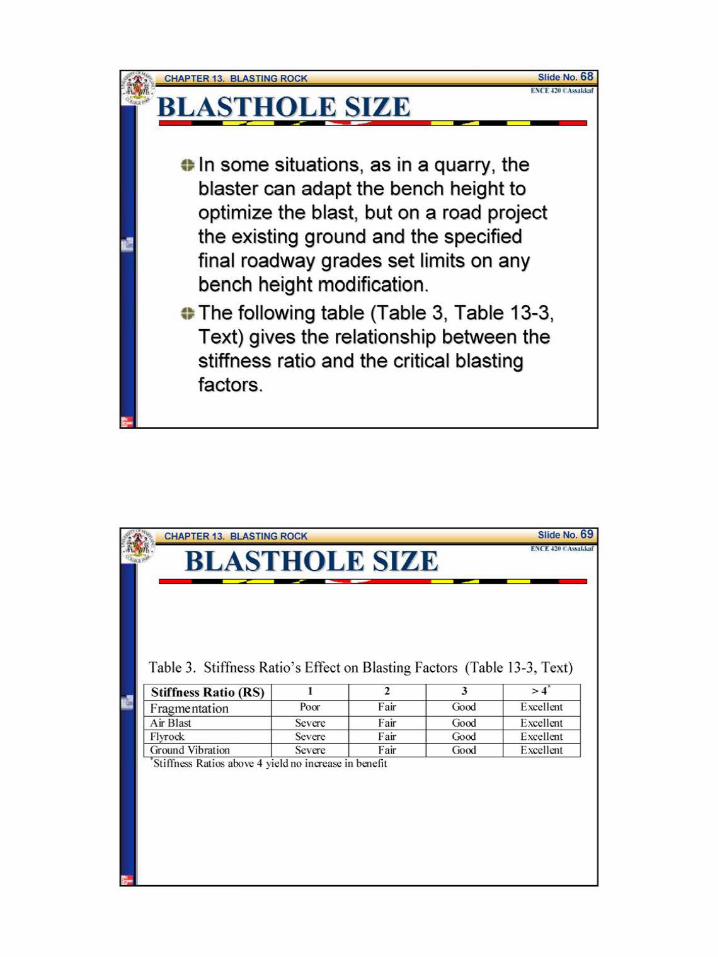
BLASTHOLE SIZE
bull~ In some situations as in a quarry the blaster can adapt the bench height to optimize the blast but on a road project the existing ground and the specified final roadway grades set limits on any bench height modification
c The following table (Table 3 Table 13-3 Text) gives the relationship between the stiffness ratio and the critical blasting factors
BLASTHOLE SIZE
Table 3 Stiffness Ratios Effect on Blasting Factors (Table 13-3 Text)
Stiffness Ratio (RS) 1 2 3 gt4
Fragmentation Poor Fair Good Excellmt Air Blast Severe Fair Good Excellmt Fl)Tock Severe Fair Good Excellmt Ground Vibration Severe Fair Good Excellmt Strffness Ratros above 4 yreld no mcrease m bmefit
BLASTHOLE SIZE
c~ One of the parameters in both Eqs 1 and 2 was the diameter of the explosive De The diameter of the explosive is limited by the diameter of the blasthole
B =(2SG+ 15)D SG
c If it is desirable to drill larger blastholes for economic reasons (usually cheaper) the burden distance will be affected
BLASTHOLE SIZE
Explosive diameter and bore hole diameter may not be the same
LINER or FILLER
BORE HOLE
ExamQle 3 or- we
o A contractor plans to use dynamite that has specific gravity of 13 to open an excavation in granite rock The drilling equipment available will drill a 5-in blastones Dynamite comes packaged in 2 75-in and 45-diameter sticks If the specifications call for a 13-ft bench height and the extent of the excavation perpendicular to the face is 100 fthow many rows of blastholes will be required for both the 2 75 and 45-diameter packages Which package of dynamite will result in lesser blasting problems
Examp]e 3 (contd) we
For the 275-in dia package fi G f G 2middot6 + 2middot9 2 8 Spec1 1c rav1ty o ran1te = =
2
2 2 1 3B = ( SG + 15) D = ( lt middot ) + 15) (275 = 6 7ft
SG 28
100 Noof rows required = + I = 1593 ~ 16 rows
67 -shy
For the 45-in dia package
2 2 1 3 B2 = ( sc + t5)n = ( lt middot gt+ t5)lt 45 = 1 o9 ft
SG 28
100 Noof rows required = + I= 1017 ~ IOrows
109 -shy
ExameJe 3 (co_ntd) we
For the 275-in dia explosive package
SR =_pound_ =_2_ =194 I Bl 67 ---shy
For the 45-in dia explosive package
SR = _ =_l_ = 119 B
2 109 -shy
Comparing the results of the stiffness ratios using Table 3 (Table 13-3 Text) the 25-in diameter explosive package has lesser blasting problem
2 3 gt4
Poor Fair Good Excellent
Severe Fair Good Excellent Severe Fair Cood Excellent Severe Fair Good Excellent
Examp]e 3 (contd) we
Table 3 Stiffness Ratios Effect on Blasting Factors (Table 13-3 Text)
Stilfuess Ratios above 4 yield no increase in benefit
ExamQle 4 or- we
Suppose that the rock blasting in Example 3 should be accomplished with a minimum stiffness ratio of 3 what will be the ideal explosive diameter
13 SR=_ =gt B=_= =433
B SR 3
2 2 3B = ( SG + 15) D = ( (l ) + Is)D = 433 ft
S(Jr 28
D~ = 1783 in
ideal explosive diameter= 175 or 134 - diameter
CKECK
2 3B = ( (- ) +15)(1 75) = 425 =gt SR =__ = ~= 306 gt 3 OK
28 B 425
c~ Proper spacing of blastholes is controlled by the initiation timing and the stiffness ratio
~~ When holes are spaced too close and fired instantaneously venting of the energy will occur with resulting air blast and flyrock
C) When the spacing is extended there is a limit beyond which fragmentation will become harsh
Before beginning a spacing analysis two questions must be answered concerning the shot
1 Will the charges be fired instantaneously or will delays be used
2 Is the stiffness ratio greater than 4
SPACING Spacing is controlled by initiation timing and stiffness ratio
(fF Instantaneous initiation SR greater than 1 but less than 4
ru= Instantaneous initiation SR equal to or greater than 4
Text p 388 equations (13-6 and 13-7)
SPACING Spacing is controlled by initiation timing and stiffness ratio
~ Delayed initiation SR greater than 1 but less than 4
f Delayed initiation SR equal to or greater than 4
Text p~ 388 equations (13-8 and 13-9)
ctAn SR of less than 4 is considered a low bench and a high bench is a SR value of 4 or greater This means that there are four cases to be considered
1 Instantaneous initiation with the SR
greater than I but less than 4
where S = spacing is= L +32B I (7)
L =bench height
2 Instantaneous initiation with the SR
equal to or greater than 4
3 Delayed initiation with the SR
greater than I but less than 4
Is L+BI (9)
4 Delayed initiation with the SR
equal to or greater than 4
Is= 14BI (9)
Note The actual spacing utilized in the field should be within 15 plus or minus the calculated value
SPACING Spacing in the field should be within plus or minus 15dego of the calculated value
Calculated spacing
-15oo
middot ExamP-le 5 ---Z
It is proposed to load 4-in diameter blasholes with bulk ANFO The contractor would like to use an 8 X 8 drill pattern Assuming the burden distance is correct will the 8-ft spacing be acceptable The bench height is 35 ft and each hole is to be fired on separate delay
ExamR]e 5 (cotd) we
B =8ft and L
Check the stiffness ratio LIB for high or low bench
Delay timing therefore use Eq 9
s =14(8) =112 ft
Range= 112 plusmn 015(112)
The spacing is not OK should be
= 35 ft
_= 35 = 44ft B 8
S =95 to 129 ft
As a minimum the pattern
8X 95
Example 6
A project in granite rock will have an average bench height of 20 ft An explosive having a specific gravity of 12 has been proposed The contractors equipment can easily drill 3-in diameter holes Assume the packaged diameter of the explosives will be 25 in Delay blasting techniques will be used Develop a blast design for the project
From Table I (Table 13-1 Text)
S fi G fG 2middot6 +2middot9 2pec1 1c rav1ty o rarute = = 75 2
B= ( 2
SG + 15)D= ( 2
(12) + 15) (25) = 593 ft
SG 2 75
ExamR]e 6 (cotd) we
Table l Density by Nominal Rock Classifications (Table 13- l Text) Rock Classification Specific Gravity Density Broken (toncu yd)
Basalt 18-30 236-253 Dibase 26-30 219-253 Diorite 28 - 30 236 -253 Dolomite 28-29 236-244 Gneiss 26 - 29 219 - 244 Granite 26-29 219-228 Gypsum 23-28 194 -226 Hematite 45-53 379-447 Limestone 24-29 194-228 Ma1ble 2 1-29 202 -228 Quartzite 20-28 219 -236 Sandstone 20-28 185- 236 Shale 24 - 28 202 - 236 Slate 25-28 228-236 Trap Rock 26 - 30 238 - 253
Examele 6 (contd) we
Hence use 6 in for the burden distance B
SF=~= 20 =33~good (accordingto Table3)B 6
The stemming depth (T) = 07 x 8 = 07(6) = 42 ft
Use 4ft for the stemming depth T
The subdrilling (J) = 03x B = 03(6) = 18 ft
Use 2 ft for subdrilling depth J
6I lt SR lt 4 and delayed initiation~ S = L+ 78 = 20 + (7)( ) 775 ft 8 8
Range= 775 plusmn 015(775) S = 66 to89 ft
As a first trial use a 6-ft burden X 8-ft spacing pattern
ExamR]e 6 (cotd) we
Table 3 Stiffness Ratios Effect on Blasting Factors (Table 13-3 Text)
Stiffness Ratio (RS) 2 3 gt 4middot Fra entation Poor Fair Good Excellent
Severe Fair Good Severe Fair Good Severe Fair Good
Excellent Excellent Excellent
POWDER COLlIMN AND POWDER FACTOR
aThe amount of explosive required to fracture a cubic yard of rock is a measure of economy of blast design
C)Table 5 (Table 13-4 Text) is a loading density chart which allows the engineer to easily calculate the weight of explosive required for a blasthole
POWDER COLUMN AND POWDER FACTOR
Table 4 Explosive Loading Density Chart in lb per ft ofColumn for a a Given Explosive Specific Gravity (Table 13-4 Text)
c_ lloJ 0~ OM
I 027 031 I 04) U ll 061 069 l j 083 -I(JJ 123 2j 170 192 3 Z4S 276 3j 334 ) 75
4)6 490
bulll 552 621 5 6SI 766 5j 824 927 6 9RI 11(13
6~ 1151 1295 7 1335 IS01 8 1743 1961 9 l1o6 2482
10 l12A 3064
Uplosi~~specific traoity
100 110 110 IJt lAO lst
034 037 041 044 048 OSI USl ~ 064 069 074 010 077 014 092 100 107 lll 104 IIS 125 136 146 156 136 150 163 177 191 2Q4 21) 2)4 Z77 319us 298 306 337 368 398 429 4 17 459 501 52 584 middot~ 626 54S 600 654 )OS 76J 817 689 158 827 896 965 10)4 151 936 1022 1107 1192 1277
1030 1133 IZ36 1))1 1442 15A$ 1226 13 147 1 1593 1716 11139 1439 1582 1726 1870 2014 2151 1668 1115 2002 2169 l336 250) 2179 2397 2615 213) 3051 ~ 2158 )034 3310 JSampS 3861 4IJ7 3405 3746 4016 4426 4767 5101
POWDER COLUMN
Powder column length is the blasthole depth minus the stemming depth
Blasthole depth =
bench height+ subdrilling
Powder column =
blasthole depth - stemming
POWDER COLlJMN AND POWDER FACTOR
= Definition The powder factor is the ratio of the total weight (lb)of explosive in powder column length to the total volume (cu yd) of rock fractured by one blasthole under the pattern area to a depth of bench depth equal L that is
P d Fow er actor =
POWDER COLUMN AND POWDER FACTOR
~Definition
The powder column length is the total hole length less stemming that is
Powder Length = L + J - T I (10)
Total Weight (lb) of Powder Column Length (11)
Total Volume under Pattern Area(cu yd)
Examele 7 we
For Example 6 calculate the powder column length the total weight of explosive used per blasthole and the powder factor From Example 6 L = 20 ft J = 4 ft and T = 4 ft Pattern = 6 X 8
Specific Gravity of Explosive = 12 Explosive diameter = 25
From Table 4 (Table 14-4 Text) Loading Density = 255 lb per ft
Powder Column Length =(L+J)-T = 20+ 2-4 = 18ft
The Total Weight of Explosive per Column = 18x 235= 4591b
Total Weight of Explosive per Hole- shyPowder Factor=
Volume of Rock Fractured under Pattern Area
6 8 20 = 459- ( ) = 1291bcu yd
27 shy
POWDER COLlIMN AND POWDER FACTOR
~ In all the examples presented so far it has been assumed that only one explosive was used in a blasthole
e If a hole is loaded with ANFO it will require a primer to initiate the explosion
e For example in the case of a powder column that is 18 ft and that will be loaded with ANFO (G8 =08) a primer will have to be placed at the bottom of the hole
POWDER COLUMN AND POWDER FACTOR
e A stick dynamite (G8 =13) will require a minimum of 8 in (0667 ft) Therefore there will be 208 in (1733 ft) of ANFO and 8 in (067 ft) of dynamite
~ The weight of explosives based on a 25-in explosive diameter will be
170 lbft X 1733 ft = 2946 lb
277 lbft X 067 ft = 185 lb
3131 lb
The total per hole is 3131 lb for 18 ft of powder column
MATERIAL HANDLING CONSIDERATIONS
~~ The economics of handling the fractured rock is a factor which should be considered in blast design
e Aithough it is critical to achieve good breakage the blast pattern will affect such considerations as the type of equipment and the bucket fill factor
c~ The appropriate piling of the blasted rock by the shot is dependent on the blast design
MATERIAL HANDLING CONSIDERATIONS
c To utilize the blast to accomplish good breakage and appropriate piling one should apply the following principles 1 Rock movement will be parallel to the burden
dimension
21nstantaneous initiation along a row causes more displacement than delayed initiation
3 Shots delayed row tyen rrJN scatter the rock more than shots fired in a V pattern
4 Shots designed in a V pttern firing sequence give maximum piling close to the face
MATERIAL HANDLING CONSIDERATIONS
w~a --f_ltbull-01~-a~~_~~-c~
PRESPLITTING ROCK
c~ Presplitting Rock is a technique of drilling and blasting which breaks rock along a relatively smooth surface (see next figure)
~~ The holes usually are 29 to 3 in in diameter and are drilled along the desired surface at spacings varying from 18 to 36 in depending on the characteristic of the rock
PRESPLITTING ROCK
c~The holes are loaded with one or two sticks of dynamite at the bottoms with smaller charges such as 125 x 4- in sticks spaced at 12-in intervals to the top of the portion of the holes to be loaded
PRESPLITTING ROCK
o It is important that the charges be less than half the blasthole diameter and they should not touch the walls of the holes
ca The appropriate load of explosive per foot of presplit blasthole is given by
~ (12)
where dec =explosive load lb per ft Dh =diameter of blasthole in
PRESPLITTING ROCK c When the formula given by Eq 12 is used to
arrive at an explosive loading the spacing between blastholes can be determined by the following equation
Is --p_=_l OD----hI_ (13)
where sp = presplit blasthole spacing in
~ Presplit blastholes are not extended below grade In the bottom of the hole a concentrated charge of 2 to 3 times dec should be placed instead of subdrilling
ExamP-le 8 ---Z
By contract specification the walls of a highway excavation through rock must be presplit The contractor will be using drilling equipment capable of drilling a 3-in hole What explosive load and hole spacing should he try for the first presplit shot on the project
d = D = (3) 2
= 032~ ec 28 28 ft
Sp =lODh =10(3) =30 in
The bottom load should be 3 x 032 = 096lb
SAFETY CONSIDERATIONS
~~An accident involving explosives may easily kill or cause serious injury
~DThe prevention of such accidents depends on careful planning and faithful observation of proper blasting practices
c~There are federal and state regulations concerning the transportation and handling of explosives
SAFETY CONSIDERATIONS
c~ Safety information on specific products is provided by the manufacturer
c~ In addition to regulations and product information there are recommended practices such as the evacuation of the blast area during the approach of an electrical storm whether electric or nonelectric initiation systems are used
SAFETY CONSIDERATIONS
~A good source for material on recommended blasting safety practices is the Institute of Makers of Explosives in New York City
e Misfire In shooting charges of explosives one or more charges may fail to explode This is referred to as a misfire
~ It is necessary to dispose of this explosive before excavating the loosened rock
c The most satisfactory method is to shoot it if possible
FACTORS AFFECTING VIBRATION
Some of the critical factors that should be considered are 1 Burden 10 Rock Type 2 Spacing 11 Rock Physical Properties 3 Subdrilling 12 Geological Features 4 Stemming Depth 13 Number ofHoles in a Row 5 Type ofStemming 14 Number ofRows 6 Bench Height 15 Row-to-Row Delays 7 Number of Decks 16 Initiator Precision 8 Charge Geometry 17 Face Angle to Structure 9 Powder Column Length 18 Explosive Energy
SPACING dont forget-shySAFETY
FACTORS AFFECTING VIBRATION
The US Bureau of Mines has proposed a formula to evaluate vibration and as a way to control blasting operation as follows
[Lgt = ~[ (14)
where Ds = scaled distance (nondimensional factor)
d = distance from shot to structure ft
W= maximum charge weight per delay lb
o A scale value of 50 or greater indicates that a shot is safe with respect to vibration
e Some regulatory agencies require a value of 60 or greater
VIBRATION
Check vibration by formula 13-12 and adjust amount of explosive per delay if necessary
Text p 397
FIRE IN THE HOLE
- barcode 550567
- barcodetext SDMS Doc ID 550567
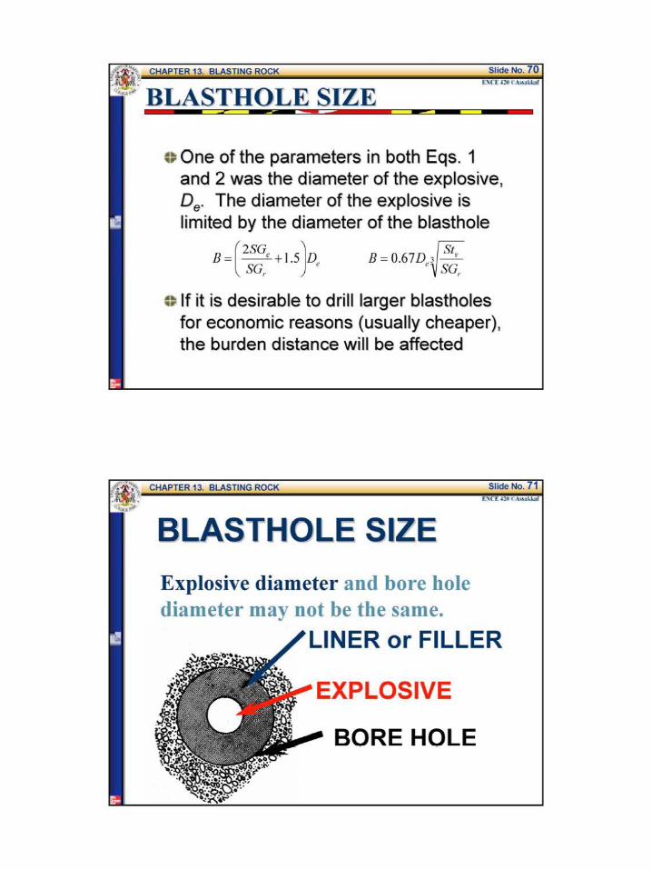
BLASTHOLE SIZE
c~ One of the parameters in both Eqs 1 and 2 was the diameter of the explosive De The diameter of the explosive is limited by the diameter of the blasthole
B =(2SG+ 15)D SG
c If it is desirable to drill larger blastholes for economic reasons (usually cheaper) the burden distance will be affected
BLASTHOLE SIZE
Explosive diameter and bore hole diameter may not be the same
LINER or FILLER
BORE HOLE
ExamQle 3 or- we
o A contractor plans to use dynamite that has specific gravity of 13 to open an excavation in granite rock The drilling equipment available will drill a 5-in blastones Dynamite comes packaged in 2 75-in and 45-diameter sticks If the specifications call for a 13-ft bench height and the extent of the excavation perpendicular to the face is 100 fthow many rows of blastholes will be required for both the 2 75 and 45-diameter packages Which package of dynamite will result in lesser blasting problems
Examp]e 3 (contd) we
For the 275-in dia package fi G f G 2middot6 + 2middot9 2 8 Spec1 1c rav1ty o ran1te = =
2
2 2 1 3B = ( SG + 15) D = ( lt middot ) + 15) (275 = 6 7ft
SG 28
100 Noof rows required = + I = 1593 ~ 16 rows
67 -shy
For the 45-in dia package
2 2 1 3 B2 = ( sc + t5)n = ( lt middot gt+ t5)lt 45 = 1 o9 ft
SG 28
100 Noof rows required = + I= 1017 ~ IOrows
109 -shy
ExameJe 3 (co_ntd) we
For the 275-in dia explosive package
SR =_pound_ =_2_ =194 I Bl 67 ---shy
For the 45-in dia explosive package
SR = _ =_l_ = 119 B
2 109 -shy
Comparing the results of the stiffness ratios using Table 3 (Table 13-3 Text) the 25-in diameter explosive package has lesser blasting problem
2 3 gt4
Poor Fair Good Excellent
Severe Fair Good Excellent Severe Fair Cood Excellent Severe Fair Good Excellent
Examp]e 3 (contd) we
Table 3 Stiffness Ratios Effect on Blasting Factors (Table 13-3 Text)
Stilfuess Ratios above 4 yield no increase in benefit
ExamQle 4 or- we
Suppose that the rock blasting in Example 3 should be accomplished with a minimum stiffness ratio of 3 what will be the ideal explosive diameter
13 SR=_ =gt B=_= =433
B SR 3
2 2 3B = ( SG + 15) D = ( (l ) + Is)D = 433 ft
S(Jr 28
D~ = 1783 in
ideal explosive diameter= 175 or 134 - diameter
CKECK
2 3B = ( (- ) +15)(1 75) = 425 =gt SR =__ = ~= 306 gt 3 OK
28 B 425
c~ Proper spacing of blastholes is controlled by the initiation timing and the stiffness ratio
~~ When holes are spaced too close and fired instantaneously venting of the energy will occur with resulting air blast and flyrock
C) When the spacing is extended there is a limit beyond which fragmentation will become harsh
Before beginning a spacing analysis two questions must be answered concerning the shot
1 Will the charges be fired instantaneously or will delays be used
2 Is the stiffness ratio greater than 4
SPACING Spacing is controlled by initiation timing and stiffness ratio
(fF Instantaneous initiation SR greater than 1 but less than 4
ru= Instantaneous initiation SR equal to or greater than 4
Text p 388 equations (13-6 and 13-7)
SPACING Spacing is controlled by initiation timing and stiffness ratio
~ Delayed initiation SR greater than 1 but less than 4
f Delayed initiation SR equal to or greater than 4
Text p~ 388 equations (13-8 and 13-9)
ctAn SR of less than 4 is considered a low bench and a high bench is a SR value of 4 or greater This means that there are four cases to be considered
1 Instantaneous initiation with the SR
greater than I but less than 4
where S = spacing is= L +32B I (7)
L =bench height
2 Instantaneous initiation with the SR
equal to or greater than 4
3 Delayed initiation with the SR
greater than I but less than 4
Is L+BI (9)
4 Delayed initiation with the SR
equal to or greater than 4
Is= 14BI (9)
Note The actual spacing utilized in the field should be within 15 plus or minus the calculated value
SPACING Spacing in the field should be within plus or minus 15dego of the calculated value
Calculated spacing
-15oo
middot ExamP-le 5 ---Z
It is proposed to load 4-in diameter blasholes with bulk ANFO The contractor would like to use an 8 X 8 drill pattern Assuming the burden distance is correct will the 8-ft spacing be acceptable The bench height is 35 ft and each hole is to be fired on separate delay
ExamR]e 5 (cotd) we
B =8ft and L
Check the stiffness ratio LIB for high or low bench
Delay timing therefore use Eq 9
s =14(8) =112 ft
Range= 112 plusmn 015(112)
The spacing is not OK should be
= 35 ft
_= 35 = 44ft B 8
S =95 to 129 ft
As a minimum the pattern
8X 95
Example 6
A project in granite rock will have an average bench height of 20 ft An explosive having a specific gravity of 12 has been proposed The contractors equipment can easily drill 3-in diameter holes Assume the packaged diameter of the explosives will be 25 in Delay blasting techniques will be used Develop a blast design for the project
From Table I (Table 13-1 Text)
S fi G fG 2middot6 +2middot9 2pec1 1c rav1ty o rarute = = 75 2
B= ( 2
SG + 15)D= ( 2
(12) + 15) (25) = 593 ft
SG 2 75
ExamR]e 6 (cotd) we
Table l Density by Nominal Rock Classifications (Table 13- l Text) Rock Classification Specific Gravity Density Broken (toncu yd)
Basalt 18-30 236-253 Dibase 26-30 219-253 Diorite 28 - 30 236 -253 Dolomite 28-29 236-244 Gneiss 26 - 29 219 - 244 Granite 26-29 219-228 Gypsum 23-28 194 -226 Hematite 45-53 379-447 Limestone 24-29 194-228 Ma1ble 2 1-29 202 -228 Quartzite 20-28 219 -236 Sandstone 20-28 185- 236 Shale 24 - 28 202 - 236 Slate 25-28 228-236 Trap Rock 26 - 30 238 - 253
Examele 6 (contd) we
Hence use 6 in for the burden distance B
SF=~= 20 =33~good (accordingto Table3)B 6
The stemming depth (T) = 07 x 8 = 07(6) = 42 ft
Use 4ft for the stemming depth T
The subdrilling (J) = 03x B = 03(6) = 18 ft
Use 2 ft for subdrilling depth J
6I lt SR lt 4 and delayed initiation~ S = L+ 78 = 20 + (7)( ) 775 ft 8 8
Range= 775 plusmn 015(775) S = 66 to89 ft
As a first trial use a 6-ft burden X 8-ft spacing pattern
ExamR]e 6 (cotd) we
Table 3 Stiffness Ratios Effect on Blasting Factors (Table 13-3 Text)
Stiffness Ratio (RS) 2 3 gt 4middot Fra entation Poor Fair Good Excellent
Severe Fair Good Severe Fair Good Severe Fair Good
Excellent Excellent Excellent
POWDER COLlIMN AND POWDER FACTOR
aThe amount of explosive required to fracture a cubic yard of rock is a measure of economy of blast design
C)Table 5 (Table 13-4 Text) is a loading density chart which allows the engineer to easily calculate the weight of explosive required for a blasthole
POWDER COLUMN AND POWDER FACTOR
Table 4 Explosive Loading Density Chart in lb per ft ofColumn for a a Given Explosive Specific Gravity (Table 13-4 Text)
c_ lloJ 0~ OM
I 027 031 I 04) U ll 061 069 l j 083 -I(JJ 123 2j 170 192 3 Z4S 276 3j 334 ) 75
4)6 490
bulll 552 621 5 6SI 766 5j 824 927 6 9RI 11(13
6~ 1151 1295 7 1335 IS01 8 1743 1961 9 l1o6 2482
10 l12A 3064
Uplosi~~specific traoity
100 110 110 IJt lAO lst
034 037 041 044 048 OSI USl ~ 064 069 074 010 077 014 092 100 107 lll 104 IIS 125 136 146 156 136 150 163 177 191 2Q4 21) 2)4 Z77 319us 298 306 337 368 398 429 4 17 459 501 52 584 middot~ 626 54S 600 654 )OS 76J 817 689 158 827 896 965 10)4 151 936 1022 1107 1192 1277
1030 1133 IZ36 1))1 1442 15A$ 1226 13 147 1 1593 1716 11139 1439 1582 1726 1870 2014 2151 1668 1115 2002 2169 l336 250) 2179 2397 2615 213) 3051 ~ 2158 )034 3310 JSampS 3861 4IJ7 3405 3746 4016 4426 4767 5101
POWDER COLUMN
Powder column length is the blasthole depth minus the stemming depth
Blasthole depth =
bench height+ subdrilling
Powder column =
blasthole depth - stemming
POWDER COLlJMN AND POWDER FACTOR
= Definition The powder factor is the ratio of the total weight (lb)of explosive in powder column length to the total volume (cu yd) of rock fractured by one blasthole under the pattern area to a depth of bench depth equal L that is
P d Fow er actor =
POWDER COLUMN AND POWDER FACTOR
~Definition
The powder column length is the total hole length less stemming that is
Powder Length = L + J - T I (10)
Total Weight (lb) of Powder Column Length (11)
Total Volume under Pattern Area(cu yd)
Examele 7 we
For Example 6 calculate the powder column length the total weight of explosive used per blasthole and the powder factor From Example 6 L = 20 ft J = 4 ft and T = 4 ft Pattern = 6 X 8
Specific Gravity of Explosive = 12 Explosive diameter = 25
From Table 4 (Table 14-4 Text) Loading Density = 255 lb per ft
Powder Column Length =(L+J)-T = 20+ 2-4 = 18ft
The Total Weight of Explosive per Column = 18x 235= 4591b
Total Weight of Explosive per Hole- shyPowder Factor=
Volume of Rock Fractured under Pattern Area
6 8 20 = 459- ( ) = 1291bcu yd
27 shy
POWDER COLlIMN AND POWDER FACTOR
~ In all the examples presented so far it has been assumed that only one explosive was used in a blasthole
e If a hole is loaded with ANFO it will require a primer to initiate the explosion
e For example in the case of a powder column that is 18 ft and that will be loaded with ANFO (G8 =08) a primer will have to be placed at the bottom of the hole
POWDER COLUMN AND POWDER FACTOR
e A stick dynamite (G8 =13) will require a minimum of 8 in (0667 ft) Therefore there will be 208 in (1733 ft) of ANFO and 8 in (067 ft) of dynamite
~ The weight of explosives based on a 25-in explosive diameter will be
170 lbft X 1733 ft = 2946 lb
277 lbft X 067 ft = 185 lb
3131 lb
The total per hole is 3131 lb for 18 ft of powder column
MATERIAL HANDLING CONSIDERATIONS
~~ The economics of handling the fractured rock is a factor which should be considered in blast design
e Aithough it is critical to achieve good breakage the blast pattern will affect such considerations as the type of equipment and the bucket fill factor
c~ The appropriate piling of the blasted rock by the shot is dependent on the blast design
MATERIAL HANDLING CONSIDERATIONS
c To utilize the blast to accomplish good breakage and appropriate piling one should apply the following principles 1 Rock movement will be parallel to the burden
dimension
21nstantaneous initiation along a row causes more displacement than delayed initiation
3 Shots delayed row tyen rrJN scatter the rock more than shots fired in a V pattern
4 Shots designed in a V pttern firing sequence give maximum piling close to the face
MATERIAL HANDLING CONSIDERATIONS
w~a --f_ltbull-01~-a~~_~~-c~
PRESPLITTING ROCK
c~ Presplitting Rock is a technique of drilling and blasting which breaks rock along a relatively smooth surface (see next figure)
~~ The holes usually are 29 to 3 in in diameter and are drilled along the desired surface at spacings varying from 18 to 36 in depending on the characteristic of the rock
PRESPLITTING ROCK
c~The holes are loaded with one or two sticks of dynamite at the bottoms with smaller charges such as 125 x 4- in sticks spaced at 12-in intervals to the top of the portion of the holes to be loaded
PRESPLITTING ROCK
o It is important that the charges be less than half the blasthole diameter and they should not touch the walls of the holes
ca The appropriate load of explosive per foot of presplit blasthole is given by
~ (12)
where dec =explosive load lb per ft Dh =diameter of blasthole in
PRESPLITTING ROCK c When the formula given by Eq 12 is used to
arrive at an explosive loading the spacing between blastholes can be determined by the following equation
Is --p_=_l OD----hI_ (13)
where sp = presplit blasthole spacing in
~ Presplit blastholes are not extended below grade In the bottom of the hole a concentrated charge of 2 to 3 times dec should be placed instead of subdrilling
ExamP-le 8 ---Z
By contract specification the walls of a highway excavation through rock must be presplit The contractor will be using drilling equipment capable of drilling a 3-in hole What explosive load and hole spacing should he try for the first presplit shot on the project
d = D = (3) 2
= 032~ ec 28 28 ft
Sp =lODh =10(3) =30 in
The bottom load should be 3 x 032 = 096lb
SAFETY CONSIDERATIONS
~~An accident involving explosives may easily kill or cause serious injury
~DThe prevention of such accidents depends on careful planning and faithful observation of proper blasting practices
c~There are federal and state regulations concerning the transportation and handling of explosives
SAFETY CONSIDERATIONS
c~ Safety information on specific products is provided by the manufacturer
c~ In addition to regulations and product information there are recommended practices such as the evacuation of the blast area during the approach of an electrical storm whether electric or nonelectric initiation systems are used
SAFETY CONSIDERATIONS
~A good source for material on recommended blasting safety practices is the Institute of Makers of Explosives in New York City
e Misfire In shooting charges of explosives one or more charges may fail to explode This is referred to as a misfire
~ It is necessary to dispose of this explosive before excavating the loosened rock
c The most satisfactory method is to shoot it if possible
FACTORS AFFECTING VIBRATION
Some of the critical factors that should be considered are 1 Burden 10 Rock Type 2 Spacing 11 Rock Physical Properties 3 Subdrilling 12 Geological Features 4 Stemming Depth 13 Number ofHoles in a Row 5 Type ofStemming 14 Number ofRows 6 Bench Height 15 Row-to-Row Delays 7 Number of Decks 16 Initiator Precision 8 Charge Geometry 17 Face Angle to Structure 9 Powder Column Length 18 Explosive Energy
SPACING dont forget-shySAFETY
FACTORS AFFECTING VIBRATION
The US Bureau of Mines has proposed a formula to evaluate vibration and as a way to control blasting operation as follows
[Lgt = ~[ (14)
where Ds = scaled distance (nondimensional factor)
d = distance from shot to structure ft
W= maximum charge weight per delay lb
o A scale value of 50 or greater indicates that a shot is safe with respect to vibration
e Some regulatory agencies require a value of 60 or greater
VIBRATION
Check vibration by formula 13-12 and adjust amount of explosive per delay if necessary
Text p 397
FIRE IN THE HOLE
- barcode 550567
- barcodetext SDMS Doc ID 550567
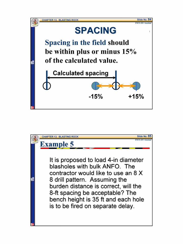

ExamR]e 6 (cotd) we
Table 3 Stiffness Ratios Effect on Blasting Factors (Table 13-3 Text)
Stiffness Ratio (RS) 2 3 gt 4middot Fra entation Poor Fair Good Excellent
Severe Fair Good Severe Fair Good Severe Fair Good
Excellent Excellent Excellent
POWDER COLlIMN AND POWDER FACTOR
aThe amount of explosive required to fracture a cubic yard of rock is a measure of economy of blast design
C)Table 5 (Table 13-4 Text) is a loading density chart which allows the engineer to easily calculate the weight of explosive required for a blasthole
POWDER COLUMN AND POWDER FACTOR
Table 4 Explosive Loading Density Chart in lb per ft ofColumn for a a Given Explosive Specific Gravity (Table 13-4 Text)
c_ lloJ 0~ OM
I 027 031 I 04) U ll 061 069 l j 083 -I(JJ 123 2j 170 192 3 Z4S 276 3j 334 ) 75
4)6 490
bulll 552 621 5 6SI 766 5j 824 927 6 9RI 11(13
6~ 1151 1295 7 1335 IS01 8 1743 1961 9 l1o6 2482
10 l12A 3064
Uplosi~~specific traoity
100 110 110 IJt lAO lst
034 037 041 044 048 OSI USl ~ 064 069 074 010 077 014 092 100 107 lll 104 IIS 125 136 146 156 136 150 163 177 191 2Q4 21) 2)4 Z77 319us 298 306 337 368 398 429 4 17 459 501 52 584 middot~ 626 54S 600 654 )OS 76J 817 689 158 827 896 965 10)4 151 936 1022 1107 1192 1277
1030 1133 IZ36 1))1 1442 15A$ 1226 13 147 1 1593 1716 11139 1439 1582 1726 1870 2014 2151 1668 1115 2002 2169 l336 250) 2179 2397 2615 213) 3051 ~ 2158 )034 3310 JSampS 3861 4IJ7 3405 3746 4016 4426 4767 5101
POWDER COLUMN
Powder column length is the blasthole depth minus the stemming depth
Blasthole depth =
bench height+ subdrilling
Powder column =
blasthole depth - stemming
POWDER COLlJMN AND POWDER FACTOR
= Definition The powder factor is the ratio of the total weight (lb)of explosive in powder column length to the total volume (cu yd) of rock fractured by one blasthole under the pattern area to a depth of bench depth equal L that is
P d Fow er actor =
POWDER COLUMN AND POWDER FACTOR
~Definition
The powder column length is the total hole length less stemming that is
Powder Length = L + J - T I (10)
Total Weight (lb) of Powder Column Length (11)
Total Volume under Pattern Area(cu yd)
Examele 7 we
For Example 6 calculate the powder column length the total weight of explosive used per blasthole and the powder factor From Example 6 L = 20 ft J = 4 ft and T = 4 ft Pattern = 6 X 8
Specific Gravity of Explosive = 12 Explosive diameter = 25
From Table 4 (Table 14-4 Text) Loading Density = 255 lb per ft
Powder Column Length =(L+J)-T = 20+ 2-4 = 18ft
The Total Weight of Explosive per Column = 18x 235= 4591b
Total Weight of Explosive per Hole- shyPowder Factor=
Volume of Rock Fractured under Pattern Area
6 8 20 = 459- ( ) = 1291bcu yd
27 shy
POWDER COLlIMN AND POWDER FACTOR
~ In all the examples presented so far it has been assumed that only one explosive was used in a blasthole
e If a hole is loaded with ANFO it will require a primer to initiate the explosion
e For example in the case of a powder column that is 18 ft and that will be loaded with ANFO (G8 =08) a primer will have to be placed at the bottom of the hole
POWDER COLUMN AND POWDER FACTOR
e A stick dynamite (G8 =13) will require a minimum of 8 in (0667 ft) Therefore there will be 208 in (1733 ft) of ANFO and 8 in (067 ft) of dynamite
~ The weight of explosives based on a 25-in explosive diameter will be
170 lbft X 1733 ft = 2946 lb
277 lbft X 067 ft = 185 lb
3131 lb
The total per hole is 3131 lb for 18 ft of powder column
MATERIAL HANDLING CONSIDERATIONS
~~ The economics of handling the fractured rock is a factor which should be considered in blast design
e Aithough it is critical to achieve good breakage the blast pattern will affect such considerations as the type of equipment and the bucket fill factor
c~ The appropriate piling of the blasted rock by the shot is dependent on the blast design
MATERIAL HANDLING CONSIDERATIONS
c To utilize the blast to accomplish good breakage and appropriate piling one should apply the following principles 1 Rock movement will be parallel to the burden
dimension
21nstantaneous initiation along a row causes more displacement than delayed initiation
3 Shots delayed row tyen rrJN scatter the rock more than shots fired in a V pattern
4 Shots designed in a V pttern firing sequence give maximum piling close to the face
MATERIAL HANDLING CONSIDERATIONS
w~a --f_ltbull-01~-a~~_~~-c~
PRESPLITTING ROCK
c~ Presplitting Rock is a technique of drilling and blasting which breaks rock along a relatively smooth surface (see next figure)
~~ The holes usually are 29 to 3 in in diameter and are drilled along the desired surface at spacings varying from 18 to 36 in depending on the characteristic of the rock
PRESPLITTING ROCK
c~The holes are loaded with one or two sticks of dynamite at the bottoms with smaller charges such as 125 x 4- in sticks spaced at 12-in intervals to the top of the portion of the holes to be loaded
PRESPLITTING ROCK
o It is important that the charges be less than half the blasthole diameter and they should not touch the walls of the holes
ca The appropriate load of explosive per foot of presplit blasthole is given by
~ (12)
where dec =explosive load lb per ft Dh =diameter of blasthole in
PRESPLITTING ROCK c When the formula given by Eq 12 is used to
arrive at an explosive loading the spacing between blastholes can be determined by the following equation
Is --p_=_l OD----hI_ (13)
where sp = presplit blasthole spacing in
~ Presplit blastholes are not extended below grade In the bottom of the hole a concentrated charge of 2 to 3 times dec should be placed instead of subdrilling
ExamP-le 8 ---Z
By contract specification the walls of a highway excavation through rock must be presplit The contractor will be using drilling equipment capable of drilling a 3-in hole What explosive load and hole spacing should he try for the first presplit shot on the project
d = D = (3) 2
= 032~ ec 28 28 ft
Sp =lODh =10(3) =30 in
The bottom load should be 3 x 032 = 096lb
SAFETY CONSIDERATIONS
~~An accident involving explosives may easily kill or cause serious injury
~DThe prevention of such accidents depends on careful planning and faithful observation of proper blasting practices
c~There are federal and state regulations concerning the transportation and handling of explosives
SAFETY CONSIDERATIONS
c~ Safety information on specific products is provided by the manufacturer
c~ In addition to regulations and product information there are recommended practices such as the evacuation of the blast area during the approach of an electrical storm whether electric or nonelectric initiation systems are used
SAFETY CONSIDERATIONS
~A good source for material on recommended blasting safety practices is the Institute of Makers of Explosives in New York City
e Misfire In shooting charges of explosives one or more charges may fail to explode This is referred to as a misfire
~ It is necessary to dispose of this explosive before excavating the loosened rock
c The most satisfactory method is to shoot it if possible
FACTORS AFFECTING VIBRATION
Some of the critical factors that should be considered are 1 Burden 10 Rock Type 2 Spacing 11 Rock Physical Properties 3 Subdrilling 12 Geological Features 4 Stemming Depth 13 Number ofHoles in a Row 5 Type ofStemming 14 Number ofRows 6 Bench Height 15 Row-to-Row Delays 7 Number of Decks 16 Initiator Precision 8 Charge Geometry 17 Face Angle to Structure 9 Powder Column Length 18 Explosive Energy
SPACING dont forget-shySAFETY
FACTORS AFFECTING VIBRATION
The US Bureau of Mines has proposed a formula to evaluate vibration and as a way to control blasting operation as follows
[Lgt = ~[ (14)
where Ds = scaled distance (nondimensional factor)
d = distance from shot to structure ft
W= maximum charge weight per delay lb
o A scale value of 50 or greater indicates that a shot is safe with respect to vibration
e Some regulatory agencies require a value of 60 or greater
VIBRATION
Check vibration by formula 13-12 and adjust amount of explosive per delay if necessary
Text p 397
FIRE IN THE HOLE
- barcode 550567
- barcodetext SDMS Doc ID 550567

POWDER COLUMN AND POWDER FACTOR
Table 4 Explosive Loading Density Chart in lb per ft ofColumn for a a Given Explosive Specific Gravity (Table 13-4 Text)
c_ lloJ 0~ OM
I 027 031 I 04) U ll 061 069 l j 083 -I(JJ 123 2j 170 192 3 Z4S 276 3j 334 ) 75
4)6 490
bulll 552 621 5 6SI 766 5j 824 927 6 9RI 11(13
6~ 1151 1295 7 1335 IS01 8 1743 1961 9 l1o6 2482
10 l12A 3064
Uplosi~~specific traoity
100 110 110 IJt lAO lst
034 037 041 044 048 OSI USl ~ 064 069 074 010 077 014 092 100 107 lll 104 IIS 125 136 146 156 136 150 163 177 191 2Q4 21) 2)4 Z77 319us 298 306 337 368 398 429 4 17 459 501 52 584 middot~ 626 54S 600 654 )OS 76J 817 689 158 827 896 965 10)4 151 936 1022 1107 1192 1277
1030 1133 IZ36 1))1 1442 15A$ 1226 13 147 1 1593 1716 11139 1439 1582 1726 1870 2014 2151 1668 1115 2002 2169 l336 250) 2179 2397 2615 213) 3051 ~ 2158 )034 3310 JSampS 3861 4IJ7 3405 3746 4016 4426 4767 5101
POWDER COLUMN
Powder column length is the blasthole depth minus the stemming depth
Blasthole depth =
bench height+ subdrilling
Powder column =
blasthole depth - stemming
POWDER COLlJMN AND POWDER FACTOR
= Definition The powder factor is the ratio of the total weight (lb)of explosive in powder column length to the total volume (cu yd) of rock fractured by one blasthole under the pattern area to a depth of bench depth equal L that is
P d Fow er actor =
POWDER COLUMN AND POWDER FACTOR
~Definition
The powder column length is the total hole length less stemming that is
Powder Length = L + J - T I (10)
Total Weight (lb) of Powder Column Length (11)
Total Volume under Pattern Area(cu yd)
Examele 7 we
For Example 6 calculate the powder column length the total weight of explosive used per blasthole and the powder factor From Example 6 L = 20 ft J = 4 ft and T = 4 ft Pattern = 6 X 8
Specific Gravity of Explosive = 12 Explosive diameter = 25
From Table 4 (Table 14-4 Text) Loading Density = 255 lb per ft
Powder Column Length =(L+J)-T = 20+ 2-4 = 18ft
The Total Weight of Explosive per Column = 18x 235= 4591b
Total Weight of Explosive per Hole- shyPowder Factor=
Volume of Rock Fractured under Pattern Area
6 8 20 = 459- ( ) = 1291bcu yd
27 shy
POWDER COLlIMN AND POWDER FACTOR
~ In all the examples presented so far it has been assumed that only one explosive was used in a blasthole
e If a hole is loaded with ANFO it will require a primer to initiate the explosion
e For example in the case of a powder column that is 18 ft and that will be loaded with ANFO (G8 =08) a primer will have to be placed at the bottom of the hole
POWDER COLUMN AND POWDER FACTOR
e A stick dynamite (G8 =13) will require a minimum of 8 in (0667 ft) Therefore there will be 208 in (1733 ft) of ANFO and 8 in (067 ft) of dynamite
~ The weight of explosives based on a 25-in explosive diameter will be
170 lbft X 1733 ft = 2946 lb
277 lbft X 067 ft = 185 lb
3131 lb
The total per hole is 3131 lb for 18 ft of powder column
MATERIAL HANDLING CONSIDERATIONS
~~ The economics of handling the fractured rock is a factor which should be considered in blast design
e Aithough it is critical to achieve good breakage the blast pattern will affect such considerations as the type of equipment and the bucket fill factor
c~ The appropriate piling of the blasted rock by the shot is dependent on the blast design
MATERIAL HANDLING CONSIDERATIONS
c To utilize the blast to accomplish good breakage and appropriate piling one should apply the following principles 1 Rock movement will be parallel to the burden
dimension
21nstantaneous initiation along a row causes more displacement than delayed initiation
3 Shots delayed row tyen rrJN scatter the rock more than shots fired in a V pattern
4 Shots designed in a V pttern firing sequence give maximum piling close to the face
MATERIAL HANDLING CONSIDERATIONS
w~a --f_ltbull-01~-a~~_~~-c~
PRESPLITTING ROCK
c~ Presplitting Rock is a technique of drilling and blasting which breaks rock along a relatively smooth surface (see next figure)
~~ The holes usually are 29 to 3 in in diameter and are drilled along the desired surface at spacings varying from 18 to 36 in depending on the characteristic of the rock
PRESPLITTING ROCK
c~The holes are loaded with one or two sticks of dynamite at the bottoms with smaller charges such as 125 x 4- in sticks spaced at 12-in intervals to the top of the portion of the holes to be loaded
PRESPLITTING ROCK
o It is important that the charges be less than half the blasthole diameter and they should not touch the walls of the holes
ca The appropriate load of explosive per foot of presplit blasthole is given by
~ (12)
where dec =explosive load lb per ft Dh =diameter of blasthole in
PRESPLITTING ROCK c When the formula given by Eq 12 is used to
arrive at an explosive loading the spacing between blastholes can be determined by the following equation
Is --p_=_l OD----hI_ (13)
where sp = presplit blasthole spacing in
~ Presplit blastholes are not extended below grade In the bottom of the hole a concentrated charge of 2 to 3 times dec should be placed instead of subdrilling
ExamP-le 8 ---Z
By contract specification the walls of a highway excavation through rock must be presplit The contractor will be using drilling equipment capable of drilling a 3-in hole What explosive load and hole spacing should he try for the first presplit shot on the project
d = D = (3) 2
= 032~ ec 28 28 ft
Sp =lODh =10(3) =30 in
The bottom load should be 3 x 032 = 096lb
SAFETY CONSIDERATIONS
~~An accident involving explosives may easily kill or cause serious injury
~DThe prevention of such accidents depends on careful planning and faithful observation of proper blasting practices
c~There are federal and state regulations concerning the transportation and handling of explosives
SAFETY CONSIDERATIONS
c~ Safety information on specific products is provided by the manufacturer
c~ In addition to regulations and product information there are recommended practices such as the evacuation of the blast area during the approach of an electrical storm whether electric or nonelectric initiation systems are used
SAFETY CONSIDERATIONS
~A good source for material on recommended blasting safety practices is the Institute of Makers of Explosives in New York City
e Misfire In shooting charges of explosives one or more charges may fail to explode This is referred to as a misfire
~ It is necessary to dispose of this explosive before excavating the loosened rock
c The most satisfactory method is to shoot it if possible
FACTORS AFFECTING VIBRATION
Some of the critical factors that should be considered are 1 Burden 10 Rock Type 2 Spacing 11 Rock Physical Properties 3 Subdrilling 12 Geological Features 4 Stemming Depth 13 Number ofHoles in a Row 5 Type ofStemming 14 Number ofRows 6 Bench Height 15 Row-to-Row Delays 7 Number of Decks 16 Initiator Precision 8 Charge Geometry 17 Face Angle to Structure 9 Powder Column Length 18 Explosive Energy
SPACING dont forget-shySAFETY
FACTORS AFFECTING VIBRATION
The US Bureau of Mines has proposed a formula to evaluate vibration and as a way to control blasting operation as follows
[Lgt = ~[ (14)
where Ds = scaled distance (nondimensional factor)
d = distance from shot to structure ft
W= maximum charge weight per delay lb
o A scale value of 50 or greater indicates that a shot is safe with respect to vibration
e Some regulatory agencies require a value of 60 or greater
VIBRATION
Check vibration by formula 13-12 and adjust amount of explosive per delay if necessary
Text p 397
FIRE IN THE HOLE
- barcode 550567
- barcodetext SDMS Doc ID 550567

MATERIAL HANDLING CONSIDERATIONS
c To utilize the blast to accomplish good breakage and appropriate piling one should apply the following principles 1 Rock movement will be parallel to the burden
dimension
21nstantaneous initiation along a row causes more displacement than delayed initiation
3 Shots delayed row tyen rrJN scatter the rock more than shots fired in a V pattern
4 Shots designed in a V pttern firing sequence give maximum piling close to the face
MATERIAL HANDLING CONSIDERATIONS
w~a --f_ltbull-01~-a~~_~~-c~
PRESPLITTING ROCK
c~ Presplitting Rock is a technique of drilling and blasting which breaks rock along a relatively smooth surface (see next figure)
~~ The holes usually are 29 to 3 in in diameter and are drilled along the desired surface at spacings varying from 18 to 36 in depending on the characteristic of the rock
PRESPLITTING ROCK
c~The holes are loaded with one or two sticks of dynamite at the bottoms with smaller charges such as 125 x 4- in sticks spaced at 12-in intervals to the top of the portion of the holes to be loaded
PRESPLITTING ROCK
o It is important that the charges be less than half the blasthole diameter and they should not touch the walls of the holes
ca The appropriate load of explosive per foot of presplit blasthole is given by
~ (12)
where dec =explosive load lb per ft Dh =diameter of blasthole in
PRESPLITTING ROCK c When the formula given by Eq 12 is used to
arrive at an explosive loading the spacing between blastholes can be determined by the following equation
Is --p_=_l OD----hI_ (13)
where sp = presplit blasthole spacing in
~ Presplit blastholes are not extended below grade In the bottom of the hole a concentrated charge of 2 to 3 times dec should be placed instead of subdrilling
ExamP-le 8 ---Z
By contract specification the walls of a highway excavation through rock must be presplit The contractor will be using drilling equipment capable of drilling a 3-in hole What explosive load and hole spacing should he try for the first presplit shot on the project
d = D = (3) 2
= 032~ ec 28 28 ft
Sp =lODh =10(3) =30 in
The bottom load should be 3 x 032 = 096lb
SAFETY CONSIDERATIONS
~~An accident involving explosives may easily kill or cause serious injury
~DThe prevention of such accidents depends on careful planning and faithful observation of proper blasting practices
c~There are federal and state regulations concerning the transportation and handling of explosives
SAFETY CONSIDERATIONS
c~ Safety information on specific products is provided by the manufacturer
c~ In addition to regulations and product information there are recommended practices such as the evacuation of the blast area during the approach of an electrical storm whether electric or nonelectric initiation systems are used
SAFETY CONSIDERATIONS
~A good source for material on recommended blasting safety practices is the Institute of Makers of Explosives in New York City
e Misfire In shooting charges of explosives one or more charges may fail to explode This is referred to as a misfire
~ It is necessary to dispose of this explosive before excavating the loosened rock
c The most satisfactory method is to shoot it if possible
FACTORS AFFECTING VIBRATION
Some of the critical factors that should be considered are 1 Burden 10 Rock Type 2 Spacing 11 Rock Physical Properties 3 Subdrilling 12 Geological Features 4 Stemming Depth 13 Number ofHoles in a Row 5 Type ofStemming 14 Number ofRows 6 Bench Height 15 Row-to-Row Delays 7 Number of Decks 16 Initiator Precision 8 Charge Geometry 17 Face Angle to Structure 9 Powder Column Length 18 Explosive Energy
SPACING dont forget-shySAFETY
FACTORS AFFECTING VIBRATION
The US Bureau of Mines has proposed a formula to evaluate vibration and as a way to control blasting operation as follows
[Lgt = ~[ (14)
where Ds = scaled distance (nondimensional factor)
d = distance from shot to structure ft
W= maximum charge weight per delay lb
o A scale value of 50 or greater indicates that a shot is safe with respect to vibration
e Some regulatory agencies require a value of 60 or greater
VIBRATION
Check vibration by formula 13-12 and adjust amount of explosive per delay if necessary
Text p 397
FIRE IN THE HOLE
- barcode 550567
- barcodetext SDMS Doc ID 550567

PRESPLITTING ROCK
c~The holes are loaded with one or two sticks of dynamite at the bottoms with smaller charges such as 125 x 4- in sticks spaced at 12-in intervals to the top of the portion of the holes to be loaded
PRESPLITTING ROCK
o It is important that the charges be less than half the blasthole diameter and they should not touch the walls of the holes
ca The appropriate load of explosive per foot of presplit blasthole is given by
~ (12)
where dec =explosive load lb per ft Dh =diameter of blasthole in
PRESPLITTING ROCK c When the formula given by Eq 12 is used to
arrive at an explosive loading the spacing between blastholes can be determined by the following equation
Is --p_=_l OD----hI_ (13)
where sp = presplit blasthole spacing in
~ Presplit blastholes are not extended below grade In the bottom of the hole a concentrated charge of 2 to 3 times dec should be placed instead of subdrilling
ExamP-le 8 ---Z
By contract specification the walls of a highway excavation through rock must be presplit The contractor will be using drilling equipment capable of drilling a 3-in hole What explosive load and hole spacing should he try for the first presplit shot on the project
d = D = (3) 2
= 032~ ec 28 28 ft
Sp =lODh =10(3) =30 in
The bottom load should be 3 x 032 = 096lb
SAFETY CONSIDERATIONS
~~An accident involving explosives may easily kill or cause serious injury
~DThe prevention of such accidents depends on careful planning and faithful observation of proper blasting practices
c~There are federal and state regulations concerning the transportation and handling of explosives
SAFETY CONSIDERATIONS
c~ Safety information on specific products is provided by the manufacturer
c~ In addition to regulations and product information there are recommended practices such as the evacuation of the blast area during the approach of an electrical storm whether electric or nonelectric initiation systems are used
SAFETY CONSIDERATIONS
~A good source for material on recommended blasting safety practices is the Institute of Makers of Explosives in New York City
e Misfire In shooting charges of explosives one or more charges may fail to explode This is referred to as a misfire
~ It is necessary to dispose of this explosive before excavating the loosened rock
c The most satisfactory method is to shoot it if possible
FACTORS AFFECTING VIBRATION
Some of the critical factors that should be considered are 1 Burden 10 Rock Type 2 Spacing 11 Rock Physical Properties 3 Subdrilling 12 Geological Features 4 Stemming Depth 13 Number ofHoles in a Row 5 Type ofStemming 14 Number ofRows 6 Bench Height 15 Row-to-Row Delays 7 Number of Decks 16 Initiator Precision 8 Charge Geometry 17 Face Angle to Structure 9 Powder Column Length 18 Explosive Energy
SPACING dont forget-shySAFETY
FACTORS AFFECTING VIBRATION
The US Bureau of Mines has proposed a formula to evaluate vibration and as a way to control blasting operation as follows
[Lgt = ~[ (14)
where Ds = scaled distance (nondimensional factor)
d = distance from shot to structure ft
W= maximum charge weight per delay lb
o A scale value of 50 or greater indicates that a shot is safe with respect to vibration
e Some regulatory agencies require a value of 60 or greater
VIBRATION
Check vibration by formula 13-12 and adjust amount of explosive per delay if necessary
Text p 397
FIRE IN THE HOLE
- barcode 550567
- barcodetext SDMS Doc ID 550567

SAFETY CONSIDERATIONS
~A good source for material on recommended blasting safety practices is the Institute of Makers of Explosives in New York City
e Misfire In shooting charges of explosives one or more charges may fail to explode This is referred to as a misfire
~ It is necessary to dispose of this explosive before excavating the loosened rock
c The most satisfactory method is to shoot it if possible
FACTORS AFFECTING VIBRATION
Some of the critical factors that should be considered are 1 Burden 10 Rock Type 2 Spacing 11 Rock Physical Properties 3 Subdrilling 12 Geological Features 4 Stemming Depth 13 Number ofHoles in a Row 5 Type ofStemming 14 Number ofRows 6 Bench Height 15 Row-to-Row Delays 7 Number of Decks 16 Initiator Precision 8 Charge Geometry 17 Face Angle to Structure 9 Powder Column Length 18 Explosive Energy
SPACING dont forget-shySAFETY
FACTORS AFFECTING VIBRATION
The US Bureau of Mines has proposed a formula to evaluate vibration and as a way to control blasting operation as follows
[Lgt = ~[ (14)
where Ds = scaled distance (nondimensional factor)
d = distance from shot to structure ft
W= maximum charge weight per delay lb
o A scale value of 50 or greater indicates that a shot is safe with respect to vibration
e Some regulatory agencies require a value of 60 or greater
VIBRATION
Check vibration by formula 13-12 and adjust amount of explosive per delay if necessary
Text p 397
FIRE IN THE HOLE
- barcode 550567
- barcodetext SDMS Doc ID 550567

VIBRATION
Check vibration by formula 13-12 and adjust amount of explosive per delay if necessary
Text p 397
FIRE IN THE HOLE
- barcode 550567
- barcodetext SDMS Doc ID 550567
FIRE IN THE HOLE
- barcode 550567
- barcodetext SDMS Doc ID 550567

- barcode 550567
- barcodetext SDMS Doc ID 550567