blastmaster 153 hose-end shutoff - … · blastmaster ® 153 hose-end shutoff. 1 blastmaster® 153...
TRANSCRIPT

Before using this equipment, read, understand and follow all instructions in the Operator’s Manuals provided with this equipment. If the user and/or assistants cannot read or understand the warnings and instructions,
the employer of the user and/or assistants must provide adequate and necessary training to ensure proper operation and compliance with all safety procedures pertaining to this equipment. If Operator’s Manuals have been lost, please visit www.marco.us, or contact Marco at 563.324.2519 for replacements. Failure to comply with the above warning could result in death or serious injury.
OPERATOR’S MANUAL
BLASTMASTER® 153 HOSE-END SHUTOFF

Blastmaster® 153 Hose-End Shutoff1
Company ProfileSince 1944, Marco has developed a strong tradition of providing innovative and reliable products and services to the surface preparation and protective coatings industries. We are the world's premier provider of Abrasives, Blasting Equipment, Coating and Painting Equipment, Engineered Systems, Rental Equipment, Safety Equipment, Service, and Repair.
Through innovative designs and a total commitment to quality, Marco manufactures products that increase production rates, create a safer workplace, and reduce maintenance costs. Marco’s industry experience, manufacturing capabilities, legendary customer service, product availability, logistics services, and technology leadership is your assurance that we deliver high quality products and services, providing the best value to you, our customer.
The Marco Difference• Industry Experience – With Marco on your team, you have access to expertise which can only come from over
65 years of industry leadership. We have organized our engineering department, production specialists, customer operations, and safety support into a “Center of Competence.” As a Marco customer, you have access to hundreds of years of cumulative experience related to your operations.
• Manufacturing Excellence – Marco is a U.S. based, ISO 9001:2008 certified manufacturer of equipment for the Surface Preparation and Protective Coatings industries. Marco’s engineers benchmark the industry to ensure that we design and manufacture superior products that set the “Gold Standard” for performance, safety, and quality.
• Legendary Customer Service – Marco’s legendary customer service team is staffed by friendly, highly-trained individuals who are focused on providing the highest level of product support, order accuracy, and customer satisfaction.
• Product Availability – We stock over 10,000 SKU’s and have over 45 shipping locations to serve North American and International markets for all major brands of blasting and painting equipment. As the largest provider of surface preparation and protective coatings equipment in the world, our inventory levels and product availability are unmatched.
• Logistics Services – Marco’s in-house logistics team is dedicated to moving your shipment anywhere in the world. We move over 14,000 truckloads every year, allowing you to save on freight costs by leveraging our buying power. Lower your process costs with a single invoice, which includes product and freight.
• Technology Leadership – Our website provides: Operator’s Manuals, Part Numbers and Schematics Guides, MSDS information, and Features, Advantages, and Benefits Guides, providing access to information 24/7. Our Extranet application allows you to receive quotes and place orders online. Our Intranet maintains a complete record of your purchase history to assist with ongoing support of your existing equipment and future purchasing decisions.
Vision Statement Marco is the world’s premier provider of Abrasives, Blasting Equipment, Coating and Painting Equipment, Engineered Systems, Rental Equipment, Safety Equipment, Service, and Repair.
Mission Statement Marco provides strong leadership and innovation to the surface preparation and protective coatings industries We dedicate our efforts to the continuous improvement of our products, services, processes, people, and most importantly, the quality of our customer’s experience.
Quality Statement Marco is committed to providing superior quality in the design, manufacturing, distribution, rental, service, and repair of our products. Our ISO 9001:2008 certification extends throughout all operations in all locations. Continuous improvement of our processes and supply chain Integration comprise the core of our business strategy for delivering exceptional quality and value in all Marco products and services.
Management Philosophy We are a company dedicated to the success of every customer and associate. We discuss, debate, challenge, measure, and test our ideas. We will be boundless and limitless in our passion to improve. Through sound leadership and dedicated associates, we will ensure a long term, profitable future for Marco, our associates, customers, and suppliers.
Blastmaster® 153 Hose-End Shutoff 2
DEFINITION OF TERMS
Company Profile . . . . . . . . . . . . . . . . . . . . . . . . 1
Definition of Terms . . . . . . . . . . . . . . . . . . . . . 2
Hazard Identifications . . . . . . . . . . . . . . . . 3-6
Air & Abrasive Consumption Chart . . . . . . 6
Daily Pre-operation Checklist . . . . . . . . . 7-8
Blastmaster® 153 Hose-End Shutoff . . 9-18
Description . . . . . . . . . . . . . . . . . . . . . . . . . . 9
Operational Requirements . . . . . . . . . . . . . . . . 9
Operating Instructions . . . . . . . . . . . . . . . . . 9-10 Before Use. . . . . . . . . . . . . . . . . . . . . . . . . . . 9 During Use. . . . . . . . . . . . . . . . . . . . . . . . . . . 9 After Using . . . . . . . . . . . . . . . . . . . . . . . . . . . 9
Installation . . . . . . . . . . . . . . . . . . . . . . . . . . . .11 Blastmaster® 153 Hose-End Shutoff . . . . . . .11 Threaded Nozzle Conversion Kit (Optional) .11
Troubleshooting . . . . . . . . . . . . . . . . . . . . . . . 12
Maintenance . . . . . . . . . . . . . . . . . . . . . . . . 13-14 Disassemble and Assemble Blastmaster® 153 Hose-End Shutoff . . . . . . . . . . . . . 13-14
This is an example of a warning. This indicates a potentially hazardous situation which, if not avoided, could result in death or serious injury.
This is an example of a notice. This indicates policy or practice directly related to safety of personnel or protection of property.
This is an example of danger. This indicates an imminently hazardous situation which, if not avoided, will result in death or serious injury.
This is an example of a caution. This indicates a potentially hazardous situation which, if not avoided, may result in minor or moderate injury. It can also be used to alert against unsafe practices.
Definition of Terms
Assembly Part Numbers & Schematics . . . 15-18 Blastmaster® 153 Hose-End Shutoff . . . . 15-16 Hose End Assemblies . . . . . . . . . . . . . . . . . 17 Type I Ceramic Nozzles. . . . . . . . . . . . . . . . 17 Threaded Nozzle Conversion Kit . . . . . . . . . 18
Maintenance Notes. . . . . . . . . . . . . . . . . 19-21
Warranty.. . . . . . . . . . . . . . . . . . . . . . . . . . . . . . 22
Disclaimer of Warranty. . . . . . . . . . . . . . . . . 22
Exclusive Remedies for Warranty Claims. . . . 22
Limitation of Remedies. . . . . . . . . . . . . . . . . 22

Blastmaster® 153 Hose-End Shutoff3
HAZARD IDENTIFICATIONS
Breathing dust containing silica could cause silicosis, a fatal lung disease. Breathing dust during abrasive blasting operations, post-blast cleaning operations, and/or servicing equipment within the abrasive blasting area may expose an individual to conditions that could cause asbestosis, lead poisoning and/or other serious or fatal diseases. Harmful dust containing toxic material from abrasives or surfaces being abrasive blasted can remain suspended in the air for long periods of time after abrasive blasting has ceased. A NIOSH-approved, well-maintained, respirator designed for the specific operation being performed must be used by anyone abrasive blasting, handling or using the abrasive, and anyone in the area of the dust.
Contact NIOSH and OSHA offices to determine the proper respirator for your specific application. The air supplied to the respirator must be at least Grade D quality as described in Compressed Gas Association Commodity Specification G-7.1 and as specified by OSHA Regulation 1910.134. Ensure air filter and respirator system hoses are not connected to non-air sources or in-plant lines that may contain nitrogen, oxygen, acetylene or other non-breathable gases. Before removing respirator, use an air monitoring instrument to determine if the atmosphere is safe to breathe.
You must comply with all OSHA, local, City, State, Province, Country and jurisdiction regulations, ordinances and standards, related to your particular work area and environment. Keep unprotected individuals out of the work area.
Abrasive blasting operators must receive thorough training on the use of abrasive resistant attire which includes: supplied-air respirator, abrasive blasting suit, safety shoes, gloves, ear protection and eye protection. Protect the operator and bystanders by complying with NIOSH and OSHA Safety Standards.
Inspect all equipment for wear or damage before and after each use. Failure to use Original Equipment Manufacturer repair parts and failure to immediately replace worn or damaged components could void warranties and cause malfunctions.
OSHA requires abrasive blasting nozzles be equipped with an operating valve, which shall be designed to be held open only by continuous hand pressure and shall close immediately upon release of hand pressure (i.e., a “deadman” control). The valve shall not be modified in any manner that would allow it to remain open without the application of continuous hand pressure by the operator. Failure to comply with the above warning could result in release of high speed abrasive and compressed air resulting in death or serious injury. OSHA 29CFR 1910.244(b)
Point the abrasive blasting nozzle only at the surface being abrasive blasted. Never point the abrasive blasting nozzle or abrasive stream at yourself or others.
Unless otherwise specified, maximum working pressure of abrasive blasting pots and related components must not exceed 125 psi. Exceeding maximum working pressure of 125 psi could cause the abrasive blasting pot and components to burst. Failure to comply with the above warning could result in death or serious injury.
Never weld, grind or drill on the abrasive blasting pot (or any pressure vessel). Doing so will void ASME certification and manufacturer’s warranty. Welding, grinding or drilling on the abrasive blasting pot (or any pressure vessel) could weaken the vessel causing it to burst. Failure to comply with the above warning could result in death or serious injury. (ASME Pressure Vessel Code, Section VIII, Division 1)
This equipment is not intended for use in any area that might be considered a hazardous location, as described in the National Electric Code NFPA 70, Article 500. Use of this equipment in a hazardous location could cause an explosion or electrocution.
Never hang objects from the abrasive blasting pot handle. Doing so may cause the abrasive blasting pot to become unstable and tip over.
Never attempt to move an abrasive blasting pot containing abrasive. Never attempt to manually move abrasive blasting pots greater than 6.5 cubic foot capacity. Always use at least two capable people to manually move an abrasive blasting pot on flat, smooth surfaces. A mechanical lifting device must be used if an abrasive blasting pot is moved in any other manner.
The use of this product for any purpose other than originally intended or altered from its original design is prohibited.

Blastmaster® 153 Hose-End Shutoff 4
HAZARD IDENTIFICATIONS
Failure to comply with ANY WARNING listed below could result in death or serious injury. This product is not for use in wet environments. Always use a Ground Fault Interrupter Circuit (GFIC) for
all electrical power source connections. Use of this product in wet environments could create a shock or electrocution hazard.
Frozen moisture could cause restrictions and obstructions in pneumatic control lines. Any restriction or obstruction in the pneumatic control lines could prevent the proper activation and deactivation of the remote control system, resulting in the release of high speed abrasive and compressed air. In conditions where moisture may freeze in the control lines an antifreeze injection system approved for this application can be installed.
Do not cut, obstruct, restrict or pinch pneumatic control lines. Doing so could prevent the proper activation and deactivation of the remote control system, resulting in the release of high speed abrasive and compressed air.
Use of Marco remote control switches with other manufacturer’s remote control systems could cause unintended activation of remote control systems resulting in the release of high speed abrasive and compressed air. Only Marco remote control switches should be used with Marco remote control systems.
Always be certain to have secure footing when abrasive blasting. There is a recoil hazard when abrasive blasting starts that may cause user to fall and misdirect the abrasive stream at operator or bystander.
Never use an abrasive blasting pot or attachments as a climbing device. The person could slip and fall. The abrasive blasting pot could become unstable and tip over.
For equipment manufactured by entities other than Marco, you must consult the Original Equipment Manufacturer operator’s manuals, information, training, instructions and warnings, for the proper and intended use of all equipment.
Flammable fumes, such as solvent and paint fumes in the work area can present an ignition or explosion hazard if allowed to collect in adequate concentrations. To reduce conditions that could result in a fire or an explosion, provide adequate ventilation, eliminate all ignition or spark sources, keep the work area free of debris, store solvents and solvent contaminated rags in approved containers, follow proper grounding procedures, do not plug/unplug power cord or turn on/off power switches when flammable fumes are present, keep a working fire extinguisher or provide another fire suppression system in the work area. Cease all operations and correct condition if a spark or ignition source is identified during operation.
Always depressurize the entire system, disconnect all power sources and lockout/tagout all components before any maintenance or troubleshooting is attempted. Failure to comply with the above warning could cause electrical shock and inadvertent activation of equipment resulting in death or serious injury.
Moving parts can present an area where crushing, pinching, entanglement or amputation may occur. Do not place body parts or foreign objects in any area where there are moving parts.
Surfaces of heated supply tanks, drums and/or lines as well as the adjoining plumbing may become hot during normal use. Do not touch these heated surfaces without proper protection. Deactivate and allow sufficient time for all surfaces to cool before attempting any maintenance.
High-pressure fluid from gun, hose leaks, or ruptured components can pierce skin and can cause a serious injury that may result in amputation. Do not point gun or spray tip at anyone or at any part of the body. Keep clear of any leaks or ruptures. Depressurize the entire system before attempting cleaning, inspecting, or servicing equipment.
Exposure to toxic fluids or fumes may occur during the normal operation of this system. Before attempting to fill, use, or service this system, read MSDS’s to know the specific hazards of the fluids you are using. Always use proper Personal Protective Equipment when attempting to fill, use, or service this system.
Blastmaster® 153 Hose-End Shutoff5
HAZARD IDENTIFICATIONS
Failure to comply with ANY CAUTION listed below may result in minor or moderate injury.Static electricity can be generated by abrasive moving through the abrasive blasting hose causing a shock
hazard. Prior to use, ground the abrasive blasting pot and abrasive blasting nozzle to dissipate static electricity. High decibel noise levels are generated during the abrasive blasting process which may cause loss of hearing.
Ensure appropriate Personal Protective Equipment and hearing protection is in use.
Failure to comply with ANY NOTICE listed below could pose a hazard to personnel or property.See Air & Abrasive Consumption Chart for estimated abrasive consumption rates and required air flow (cubic feet
per minute). Your system must meet these minimum requirements to ensure proper function and performance.Always use abrasive that is dry and properly screened. This will reduce the potential for obstructions to enter the
remote control system, abrasive metering valve and abrasive blasting nozzle.Moisture build-up occurs when air is compressed. Any moisture within the abrasive blasting system will cause
abrasive to clump, clogging metering valves, hoses and nozzles. Install an appropriately sized moisture separator at the inlet of the abrasive blasting system. Leave the moisture separator petcock slightly open to allow for constant release of water. If insufficient volume of air exists and petcock is unable to be left open (at all times) petcock should be opened frequently to release water.
To reduce abrasive intrusion in the air supply hose, depressurize the abrasive blasting pot before shutting off air supply from compressor.
Inspect abrasive blasting nozzle before placing into service. Damage to abrasive blasting nozzle liner or jacket may occur during shipping. If you receive a damaged abrasive blasting nozzle, contact your distributor immediately for replacement. Abrasive blasting nozzles placed into service may not be returned. Abrasive blasting nozzle liners are made of fragile materials and can be damaged by rough handling and striking against hard surfaces. Never use a abrasive blasting nozzle.
Abrasive blasting at optimal pressure for the abrasive used is critical to productivity. Example: For an abrasive with an optimal abrasive blasting pressure of 100 psi at the abrasive blasting nozzle, one pound per square inch of pressure loss will reduce abrasive blasting efficiency by 1.5%. A 10 psi reduction in air pressure will cause a 15% loss of efficiency. Use a Needle Pressure Gauge to identify pressure drops in your system. Consult with your abrasive supplier for the requirements of your abrasive.
Replace abrasive blasting nozzle if liner or jacket is cracked or damaged. Replace abrasive blasting nozzle if original orifice size has worn 1/16” or more. Determine abrasive blasting nozzle wear by inserting a drill bit 1/16” larger than original size of abrasive blasting nozzle orifice. If the drill bit passes through abrasive blasting nozzle, replacement is needed.

Blastmaster® 153 Hose-End Shutoff 6
AIR & ABRASIVE CONSUMPTION CHART
Failure to comply with ANY NOTICE listed below could pose a hazard to personnel or property. See Air & Abrasive Consumption Chart for estimated abrasive consumption rates and required air flow
(cubic feet per minute). Your system must meet these minimum requirements to ensure proper function and performance.
When it comes to air & abrasive mixtures, more is not necessarily better. Optimum abrasive blasting efficiency takes place when a lean air & abrasive mixture is used. To correctly set the abrasive metering valve, begin with the valve fully closed and slowly increase the amount of abrasive entering the airstream. As you increase the abrasive flow, watch for a “blue flame” at the exit of the abrasive blasting nozzle. Faster cutting, reduced abrasive consumption and lower clean up costs, are benefits of the “blue flame”.
Abrasive blasting at optimal pressure for the abrasive used is critical to productivity. Example: For an abrasive with an optimal abrasive blasting pressure of 100 psi at the abrasive blasting nozzle, one pound per square inch of pressure loss will reduce abrasive blasting efficiency by 1.5%. A 10 psi reduction in air pressure will cause a 15% loss of efficiency. Use a Needle Pressure Gauge to identify pressure drops in your system. Consult with your abrasive supplier for the requirements of your abrasive.
Replace abrasive blasting nozzle if liner or jacket is cracked or damaged. Replace abrasive blasting nozzle if original orifice size has worn 1/16” or more. Determine abrasive blasting nozzle wear by inserting a drill bit 1/16” larger than original size of abrasive blasting nozzle orifice. If the drill bit passes through abrasive blasting nozzle, replacement is needed.
Inspect abrasive blasting nozzle before placing into service. Damage to abrasive blasting nozzle liner or jacket may occur during shipping. If you receive a damaged abrasive blasting nozzle, contact your distributor immediately for replacement. Abrasive blasting nozzles placed into service may not be returned. Abrasive blasting nozzle liners are made of fragile materials and can be damaged by rough handling and striking against hard surfaces. Never use a abrasive blasting nozzle.
*Abrasive consumption is based on abrasive with a bulk density of 100 lbs per Cubic Foot
Air & Abrasive Consumption Chart*NozzleOrifice
Pressure at the Nozzle (PSI) Air (in cfm), Abrasive & Compressor Requirements50 60 70 80 90 100 125 140
No. 2 (1/8ˮ)
11672.5
13773
15883.5
17101
4
181124.5
20123
5
251525.5
281706.2
Air (cfm)Abrasive (lbs/hr)Compressor Horsepower
No. 3 (3/16ˮ)
26150
6
30171
7
33196
8
38216
9
4123810
4526410
5531912
6235713
Air (cfm)Abrasive (lbs/hr)Compressor Horsepower
No. 4 (1/4ˮ)
4726811
5431212
6135414
6840816
7444817
8149418
9860822
11068125
Air (cfm)Abrasive (lbs/hr)Compressor Horsepower
No. 5 (5/16ˮ)
7746818
8953420
10160423
11367226
12674028
13781231
16898237
188110041
Air (cfm)Abrasive (lbs/hr)Compressor Horsepower
No. 6 (3/8ˮ)
10866824
12676428
14386432
16196036
1731052
39
196115244
2371393
52
2651560
58
Air (cfm)Abrasive (lbs/hr)Compressor Horsepower
No. 7 (7/16ˮ)
14789633
1701032
38
194117644
2171312
49
2401448
54
2541584
57
3141931
69
3522163
77
Air (cfm)Abrasive (lbs/hr)Compressor Horsepower
No. 8 (1/2ˮ)
195116044
2241336
50
2521512
56
2801680
63
3091856
69
3382024
75
4092459
90
4582754101
Air (cfm)Abrasive (lbs/hr)Compressor Horsepower
No. 10 (5/8ˮ)
308187568.5
356214079.5
4042422
90
4522690100.5
5042973112
5483250122
6633932146
7424405165
Air (cfm)Abrasive (lbs/hr)Compressor Horsepower
No. 12 (3/4ˮ)
4322672
96
5043056112
5723456127
6443840143
6924208154
7844608174.5
9485570209
10626238236
Air (cfm)Abrasive (lbs/hr)Compressor Horsepower

Blastmaster® 153 Hose-End Shutoff7
“THE BIG PICTURE”
3
5
7
4
4
3
21
8
9
1714
1615
1319
18
10
20
23
21
424
272625
22
28
5
3
6
11
12
Blastmaster® 153 Hose-End Shutoff 8
DAILY PRE-OPERATION CHECKLIST
Daily Pre-operation Checklist 1. Abrasive
2. Air Compressor
3. Air Hose Couplings & Gaskets
4. Air Hose
5. Safety Cable
6. Ambient Air Pump*
7. Breathing Air Filter
8. CO Monitor
9. Breathing Line
10. Climate Control Device
11. Abrasive Blasting Suit
12. Gloves
13. Abrasive Blasting Nozzle
14. Lighting System*
15. Abrasive Blasting Nozzle Holder
16. Remote Control Switch
17. Supplied-Air Respirator
18. Control Line
19. Abrasive Blasting Hose
20. Abrasive Blasting Hose Couplings & Gaskets 21. Abrasive Metering Valve
22. Remote Control System
23. Moisture Separator
24. Abrasive Blasting Pot Exhaust Muffler
25. Abrasive Blasting Pot
26. Abrasive Blasting Pot Screen
27. Abrasive Blasting Pot Lid
28. Aftercooler*
* Optional or alternative device. Ask your Marco Representative for more details.
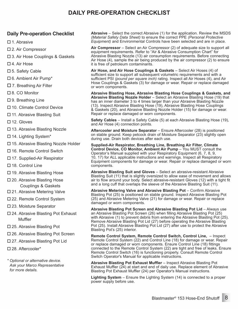
Abrasive – Select the correct Abrasive (1) for the application. Review the MSDS (Material Safety Data Sheet) to ensure the correct PPE (Personal Protective Equipment) and Environmental Controls have been selected and are in place.Air Compressor – Select an Air Compressor (2) of adequate size to support all equipment requirements. Refer to “Air & Abrasive Consumption Chart” for Abrasive Blasting Nozzle (13) air consumption requirements. Before connecting Air Hose (4), sample the air being produced by the air compressor (2) to ensure it is free of petroleum contaminants.Air Hose, and Air Hose Couplings & Gaskets – Select Air Hoses (4) of sufficient size to support all subsequent volumetric requirements and with a sufficient PSI (pound per square inch) rating. Inspect all Air Hoses (4), and Air Hose Couplings & Gaskets (3) for damage or wear. Repair or replace damaged or worn components.Abrasive Blasting Hose, Abrasive Blasting Hose Couplings & Gaskets, and Abrasive Blasting Nozzle Holder – Select an Abrasive Blasting Hose (19) that has an inner diameter 3 to 4 times larger than your Abrasive Blasting Nozzle (13). Inspect Abrasive Blasting Hose (19), Abrasive Blasting Hose Couplings & Gaskets (20), and Abrasive Blasting Nozzle Holder (15) for damage or wear. Repair or replace damaged or worn components.Safety Cables – Install a Safety Cable (5) at each Abrasive Blasting Hose (19), and Air Hose (4) connection points.Aftercooler and Moisture Separator – Ensure Aftercooler (28) is positioned on stable ground. Keep petcock drain of Moisture Separator (23) slightly open during use. Drain both devices after each use.Supplied-Air Respirator, Breathing Line, Breathing Air Filter, Climate Control Device, CO Monitor, Ambient Air Pump – You MUST consult the Operator’s Manual supplied with your Respiratory Equipment (6, 7, 8, 9, 10, 17) for ALL applicable instructions and warnings. Inspect all Respiratory Equipment components for damage or wear. Repair or replace damaged or worn components.Abrasive Blasting Suit and Gloves – Select an abrasive-resistant Abrasive Blasting Suit (11) that is slightly oversized to allow ease of movement and allows air to flow around your body. Select abrasive-resistant Gloves (12) with a tight fit and a long cuff that overlaps the sleeve of the Abrasive Blasting Suit (11).Abrasive Metering Valve and Abrasive Blasting Pot – Confirm Abrasive Blasting Pot (25) is positioned on stable ground. Inspect Abrasive Blasting Pot (25) and Abrasive Metering Valve (21) for damage or wear. Repair or replace damaged or worn components.Abrasive Blasting Pot Screen and Abrasive Blasting Pot Lid – Always use an Abrasive Blasting Pot Screen (26) when filling Abrasive Blasting Pot (25) with Abrasive (1) to prevent debris from entering the Abrasive Blasting Pot (25). Remove Abrasive Blasting Pot Lid (27) before operating the Abrasive Blasting Pot (25). Install Abrasive Blasting Pot Lid (27) after use to protect the Abrasive Blasting Pot’s (25) interior.Remote Control System, Remote Control Switch, Control Line, – Inspect Remote Control System (22) and Control Line (18) for damage or wear. Repair or replace damaged or worn components. Ensure Control Line (18) fittings connected to the Remote Control System (22) are tight and free of leaks. Ensure Remote Control Switch (16) is functioning properly. Consult Remote Control Switch Operator's Manual for applicable instructions.Abrasive Blasting Pot Exhaust Muffler – Inspect Abrasive Blasting Pot Exhaust Muffler (24) at start and end of daily use. Replace element of Abrasive Blasting Pot Exhaust Muffler (24) per Operator's Manual instructions.Lighting System – Ensure the Lighting System (14) is connected to a proper power supply before use.

Blastmaster® 153 Hose-End Shutoff9
DescriptionThe hose-end shutoff gives an operator the ability to remotely activate and deactivate the flow of air and abrasive at the abrasive blasting nozzle. This increases productivity and eliminates the need for a pot tender. The Blastmaster® 153 Hose-End Shutoff is an OSHA-compliant abrasive blasting hose-end shutoff valve. When the spring-assisted lever is moved to the blasting position, the air and abrasive mixture in the abrasive blasting hose is released, allowing it to exit the abrasive blasting nozzle. When the lever is released, it returns to the non-blasting position, deactivating the flow of the air and abrasive mixture exiting the abrasive blasting nozzle. Typical applications include monument engraving, touch-up work, automobile restoration, and construction equipment maintenance. Common abrasives used include aluminum oxide, garnet, glass bead, mineral abrasives, and staurolite.
Operational RequirementsThe following may cause safety hazards or reduced performance:• Improper installation and/or maintenance of components• Use of anything other than hand pressure to activate Hose-End Shutoff• Use of an air supply with pressure greater than 125 PSI
Operating InstructionsFig. 1Before using:• Inspect all parts for signs of wear or damage. Remove Blastmaster® 153 Hose-End
Shutoff from service if excessive wear or damage is found until parts can be replaced.• Test Lever (5) by rotating it from Fully-Closed to Fully-Open. If Lever does not return to the Fully-Closed position, remove Blastmaster® 153 Hose-End Shutoff from service until device is repaired and operating properly.• Make sure Blastmaster® 153 Hose-End Shutoff is securely attached to Nozzle Holder Base (4) and Nozzle Holder Base is securely attached to Hose End (6).• Install Nozzle Washer in Outlet Port (A). • Install Nozzle (2) (not included) in Nozzle Cap (1). See Installation Instructions.• Ensure Nozzle Cap (1) is securely attached to Blastmaster® 153 Hose-End Shutoff.• Pressurize the abrasive blasting pot. (See abrasive blasting pot Operator's Manual.)
During use:• To operate, quickly swing Lever (5) from the Fully-Closed to the Fully-Open position. DO NOT use the Blastmaster® 153 Hose-End Shutoff to restrict the abrasive flow. Metering of the abrasive should occur at the abrasive metering valve on the abrasive blasting pot. Using the Blastmaster® 153 Hose-End Shutoff as a metering device will greatly increase the wear of parts.• To cease operation, release Lever (5) and allow it to return to the Fully-Closed position.
After use:• Depressurize abrasive blasting pot. (See abrasive blasting pot Operator's Manual.)• Move Lever (5) to the Fully-Open position to release any residual pressure present in the abrasive blasting hose.• Remove Nozzle Cap (1) and Nozzle Washer (3). Extract Ceramic Nozzle (2) from Nozzle Cap.• Remove Blastmaster® 153 Hose-End Shutoff from Nozzle Holder Base (4).• Inspect parts for wear or damage. Replace parts showing excessive wear or damage before next use.
Use of Marco remote control switches with other manufacturer’s remote control systems could cause unintended activation of remote control systems resulting in the release of high speed media and compressed air. Only Marco remote control switches should be used with Marco remote control systems. Failure to comply with the above warning could result in death or serious injury.
OSHA requires abrasive blasting nozzles be equipped with an operating valve, which shall be designed to be held open only by continuous hand pressure and shall close immediately upon release of hand pressure (i.e., a "deadman" control). The valve shall not be modified in any manner that would allow it to remain open without the application of continuous hand pressure by the operator. Failure to comply with the above warning could result in release of high speed media and compressed air resulting in death or serious injury. OSHA 29 CFR 1910.244(b)
Do not wear loose clothing while operating Blastmaster® 153 Hose-End Shutoff or allow clothing to interfere with the operation of control valve. Failure to comply with the above warning could result in death or serious injury.

Blastmaster® 153 Hose-End Shutoff 10
OPERATING INSTRUCTIONSFigure 1: Blastmaster® 153 Hose-End Shutoff
6Fully-Closed
Fully-Open
4
Always depressurize the entire system, disconnect all power sources and lockout/tagout all components before any maintenance or troubleshooting is attempted. Failure to comply with the above warning could cause electrical shock and inadvertent activation of equipment resulting in death or serious injury.
1 2 3 4
5
A
6

Blastmaster® 153 Hose-End Shutoff11
Figure 2: Install Blastmaster® 153 Hose-End Shutoff
INSTALLATION
InstallationAn optional Threaded Nozzle Adapter kit allows for use of standard threaded abrasive blasting nozzles. These nozzles include liners that can provide longer operational life than ceramic nozzles.Fig. 31) Insert Nozzle Washer (2) into Valve Body (1).2) Insert Spacer (3) into Valve Body (1), and install Threaded Adapter (5).3) Insert Nozzle Washer (4), seating squarely against Spacer (3).4) Pull Lever (7) to Fully-Open position and install Threaded Nozzle (6), tightening until seated.5) Release Lever (7).
1 5432 6
7
Always depressurize the entire system, disconnect all power sources and lockout/tagout all components before any maintenance or troubleshooting is attempted. Failure to comply with the above warning could cause electrical shock and inadvertent activation of equipment resulting in death or serious injury.
InstallationFig. 21) Install O-Ring (7) over threads of Nozzle Holder Base (8). Insert Rubber Liner (6) into Nozzle Holder Base.2) Insert Ceramic Nozzle (2) into Nozzle Cap (1). Insert Nozzle Washer (3) into Valve Body (5). 3) Pull Lever (4) to the Fully-Open position and install Nozzle Cap Assembly on to Valve Body (5), ensuring a tight fit. NOTE: A seal is formed between Valve Washer and Nozzle Washer (3) only when Nozzle Washer is properly installed with Ceramic Nozzle (2) and Nozzle Cap (1).4) Install Valve Body (5) onto Nozzle Holder Base (8), assuring a tight fit.
Figure 3: Install Threaded Nozzle Conversion Kit
1 2 3 4 5 6 7 8
Blastmaster® 153 Hose-End Shutoff 12
TROUBLESHOOTING
Always depressurize the entire system, disconnect all power sources and lockout/tagout all components before any maintenance or troubleshooting is attempted. Failure to comply with the above warning could cause electrical shock and inadvertent activation of equipment resulting in death or serious injury.
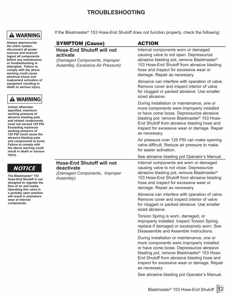
If the Blastmaster® 153 Hose-End Shutoff does not function properly, check the following:
Unless otherwise specified, maximum working pressure of abrasive blasting pots and related components must not exceed 125 PSI. Exceeding maximum working pressure of 125 PSI could cause the abrasive blasting pots and components to burst. Failure to comply with the above warning could result in death or serious injury.
The Blastmaster® 153 Hose-End Shutoff is not designed to regulate the flow of air and media. Operating this valve in a partially open position will result in premature wear of internal components.
SYMPTOM (Cause) ACTIONHose-End Shutoff will not activate(Damaged Components, Improper Assembly, Excessive Air Pressure)
Internal components worn or damaged causing valve to not open. Depressurize abrasive blasting pot, remove Blastmaster® 153 Hose-End Shutoff from abrasive blasting hose and inspect for excessive wear or damage. Repair as necessary.Abrasive can interfere with operation of valve. Remove cover and inspect interior of valve for clogged or packed abrasive. Use smaller sized abrasive.During installation or maintenance, one or more components were improperly installed or have come loose. Depressurize abrasive blasting pot, remove Blastmaster® 153 Hose-End Shutoff from abrasive blasting hose and inspect for excessive wear or damage. Repair as necessary.Air pressure over 125 PSI can make opening valve difficult. Reduce air pressure to make for easier activation.See abrasive blasting pot Operator’s Manual.
Hose-End Shutoff will not deactivate(Damaged Components, Improper Assembly)
Internal components are worn or damaged causing valve to not close. Depressurize abrasive blasting pot, remove Blastmaster® 153 Hose-End Shutoff from abrasive blasting hose and inspect for excessive wear or damage. Repair as necessary.Abrasive can interfere with operation of valve. Remove cover and inspect interior of valve for clogged or packed abrasive. Use smaller sized abrasive.Torsion Spring is worn, damaged, or improperly installed. Inspect Torsion Spring, replace if damaged or excessively worn. See Disassemble and Assemble Instructions.During installation or maintenance, one or more components were improperly installed or have come loose. Depressurize abrasive blasting pot, remove Blastmaster® 153 Hose-End Shutoff from abrasive blasting hose and inspect for excessive wear or damage. Repair as necessary.See abrasive blasting pot Operator’s Manual.

Blastmaster® 153 Hose-End Shutoff13
Disassemble and Assemble Blastmaster® 153 Hose-End Shutoff
MAINTENANCE
Maintenance of the Blastmaster® 153 Hose-End Shutoff is limited to the daily cleaning and the immediate replacement of damaged or worn parts.Fig. 4Disassemble:1) Remove Blastmaster® 153 Hose-End Shutoff from abrasive blasting hose.2) Remove Nozzle Holder Base (10) from Valve Body (7), if installed.3) Remove Rubber Liner (8), and O-Ring (9) from Nozzle Holder Base (10).4) Remove Nozzle Cap (1), Ceramic Nozzle (2), and Nozzle Washer (3) from Valve Body (7).5) Remove six Hex Cap Screws (4), Cover (5), and Cover Gasket (6).6) Remove E-clip (13) from Spindle (16).7) Remove Hex Cap Screw (14), while holding Nut (15) in position, releasing Torsion Spring (12). Remove Torsion Spring.8) Rotate Lever (11) until Shut-off Arm (18) extends through top opening and is accessible. Remove Hex Cap Screw (17). Remove Valve Washer (23), Rubber Washer (22), and Valve Disc Stem (21).9) Remove Valve Washer (23) and Rubber Washer (22) from Valve Disc Stem (21).10)Rotate Lever (11) until Shut-off Arm (18) makes contact with Valve Body (7) to expose Socket Screw (20). Remove Socket Screw and Star Lock Washer (19), releasing Shut-off Arm from Spindle (16).11) Remove Set Screw (26) from Spindle (16), and remove Lever (11).12)Unscrew Spindle Bushings (24) from Valve Body (7), and remove O-rings (25).13) Inspect Valve Insert (27) for wear or damage. Replace as necessary.Assemble:1) Apply a light coat of blue thread locker to fine threads (c) on Valve Insert (27). Install Valve Insert into Valve Body (7).2) Apply a light coat of petroleum jelly to O-Rings (25). Install into Spindle Bushings (24).3) Apply a light coat of petroleum jelly to Spindle Hips (a). Loosely thread one Spindle Bushing (24) into Valve Body (7). 4) Install Spindle (16) by inserting shaft through Spindle Bushing (24).5) Install remaining Spindle Bushing (24) by slipping it over Spindle (16). Loosely thread Spindle Bushing into Valve Body (7). Tighten Spindle Bushings.6) Insert Lever (11) into Spindle (16). Lock Lever (11) in place with Set Screw (26).7) Rotate Spindle (16) until notch (b) is visible and facing toward valve entry. Using Hex Screw (20) and Star Lock Washer (19), install Shut-off Arm (18).8) Install Valve Washer (23) and Rubber Washer (22) onto Valve Disc Stem (21). Using Hex Cap Screw (17), install Valve Disc Stem Assembly onto Shut-off Arm (18).9) Rotate Spindle (16) until Valve Stem Assembly is seated into Valve Insert (27). Insert inner tab of Torsion Spring (12) into slot on Spindle. Install E-Clip (13).10)Insert Hex Cap Screw (14) through loop end of Torsion Spring (12). Install Nut (15) between Torsion Spring and Valve Body (7). Thread Hex Cap Screw (14) into Valve Body until base of the screw's cap aligns with E-Clip (13). Tighten Nut against Valve Body.11) Stack Cover (5) over Cover Gasket (6), align over top Valve Body (7), and install with Hex Cap Screws (4).12) Slip O-Ring (9) over threads on Nozzle Holder Base (10). Install Rubber Liner (8) into Nozzle Holder Base. Thread Nozzle Holder Base assembly into Valve Body (7).13)Install Ceramic Nozzle (2) into Nozzle Cap (1). Install Nozzle Washer (3) into Valve Body (7).14) Pull Lever (11) back to the Fully-Open position, then thread Nozzle Cap (1) onto Valve Body (7), ensuring a tight fit.
Always depressurize the entire system, disconnect all power sources and lockout/tagout all components before any maintenance or troubleshooting is attempted. Failure to comply with the above warning could cause electrical shock and inadvertent activation of equipment resulting in death or serious injury.
The use of this product for any purpose other than originally intended or altered from its original design is prohibited. Failure to comply with the above warning could result in death or serious injury.

Blastmaster® 153 Hose-End Shutoff 14
Figure 4: Disassemble and Assemble Blastmaster® 153 Hose-End Shutoff
MAINTENANCE
11
12
7
6
5
4
3 98
20191817
16
15
12
13
14
7
2425
27
162625
24
23
2111
b
c
a
22
10
Blastmaster® 153 Hose-End Shutoff15
ASSEMBLY PART NUMBERS
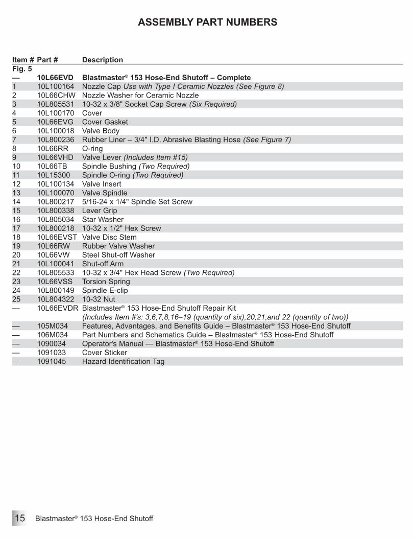
Item # Part # DescriptionFig. 5— 10L66EVD Blastmaster® 153 Hose-End Shutoff – Complete1 10L100164 Nozzle Cap Use with Type I Ceramic Nozzles (See Figure 8)2 10L66CHW Nozzle Washer for Ceramic Nozzle3 10L805531 10-32 x 3/8" Socket Cap Screw (Six Required)4 10L100170 Cover5 10L66EVG Cover Gasket6 10L100018 Valve Body7 10L800236 Rubber Liner – 3/4" I.D. Abrasive Blasting Hose (See Figure 7)8 10L66RR O-ring9 10L66VHD Valve Lever (Includes Item #15)10 10L66TB Spindle Bushing (Two Required)11 10L15300 Spindle O-ring (Two Required)12 10L100134 Valve Insert13 10L100070 Valve Spindle14 10L800217 5/16-24 x 1/4" Spindle Set Screw15 10L800338 Lever Grip16 10L805034 Star Washer17 10L800218 10-32 x 1/2" Hex Screw18 10L66EVST Valve Disc Stem19 10L66RW Rubber Valve Washer20 10L66VW Steel Shut-off Washer21 10L100041 Shut-off Arm22 10L805533 10-32 x 3/4" Hex Head Screw (Two Required)23 10L66VSS Torsion Spring24 10L800149 Spindle E-clip25 10L804322 10-32 Nut— 10L66EVDR Blastmaster® 153 Hose-End Shutoff Repair Kit
(Includes Item #'s: 3,6,7,8,16–19 (quantity of six),20,21,and 22 (quantity of two))— 105M034 Features, Advantages, and Benefits Guide – Blastmaster® 153 Hose-End Shutoff— 106M034 Part Numbers and Schematics Guide – Blastmaster® 153 Hose-End Shutoff— 1090034 Operator's Manual — Blastmaster® 153 Hose-End Shutoff— 1091033 Cover Sticker— 1091045 Hazard Identification Tag

Blastmaster® 153 Hose-End Shutoff 16
Figure 5
SCHEMATIC
9
6
5
4
3
2 87
17162122
26
25
23
24
22
6
1011
12
131411
10
20
189
19
15
1
Blastmaster® 153 Hose-End Shutoff17
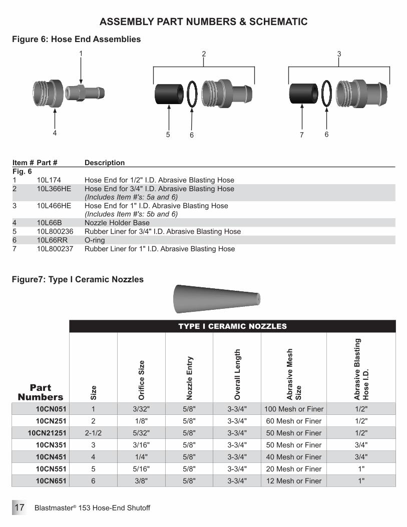
ASSEMBLY PART NUMBERS & SCHEMATICFigure 6: Hose End Assemblies
Part Numbers
TYPE I CERAMIC NOZZLES
Size
Orifi
ce S
ize
Noz
zle
Entr
y
Ove
rall
Leng
th
Abr
asiv
e M
esh
Size
Abr
asiv
e B
last
ing
Hos
e I.D
.
10CN051 1 3/32" 5/8" 3-3/4" 100 Mesh or Finer 1/2"10CN251 2 1/8" 5/8" 3-3/4" 60 Mesh or Finer 1/2"
10CN21251 2-1/2 5/32" 5/8" 3-3/4" 50 Mesh or Finer 1/2"10CN351 3 3/16" 5/8" 3-3/4" 50 Mesh or Finer 3/4"10CN451 4 1/4" 5/8" 3-3/4" 40 Mesh or Finer 3/4"10CN551 5 5/16" 5/8" 3-3/4" 20 Mesh or Finer 1"10CN651 6 3/8" 5/8" 3-3/4" 12 Mesh or Finer 1"
Figure7: Type I Ceramic Nozzles
7 64
Item # Part # DescriptionFig. 61 10L174 Hose End for 1/2" I.D. Abrasive Blasting Hose2 10L366HE Hose End for 3/4" I.D. Abrasive Blasting Hose
(Includes Item #'s: 5a and 6)3 10L466HE Hose End for 1" I.D. Abrasive Blasting Hose
(Includes Item #'s: 5b and 6)4 10L66B Nozzle Holder Base5 10L800236 Rubber Liner for 3/4" I.D. Abrasive Blasting Hose6 10L66RR O-ring7 10L800237 Rubber Liner for 1" I.D. Abrasive Blasting Hose
1 3
5
2
6

Blastmaster® 153 Hose-End Shutoff 18
ASSEMBLY PART NUMBERS & SCHEMATICFigure 8: Threaded Nozzle Conversion Kit
Item # Part # DescriptionFig. 81 10L100222 Threaded Nozzle Conversion Kit
(Includes Item #'s: 2,3,4,5)2 10L66CHW Nozzle Washer3 10L66HS Spacer4 10L850008 Nozzle Washer5 10L66NCNV Threaded Adapter— — Threaded Nozzle (Not Included. Contact Marco for details)
432
1
5

Blastmaster® 153 Hose-End Shutoff19
MAINTENANCE NOTES
DATE TYPE OF SERVICE PART NUMBER

Blastmaster® 153 Hose-End Shutoff 20
MAINTENANCE NOTES
DATE TYPE OF SERVICE PART NUMBER

Blastmaster® 153 Hose-End Shutoff21
MAINTENANCE NOTES
DATE TYPE OF SERVICE PART NUMBER

Blastmaster® 153 Hose-End Shutoff 22
LIMITED WARRANTYSeller warrants to the original purchaser that the Product covered by this Limited Warranty will remain free from defects in workmanship or material under normal commercial use and service for a period of one year from the date of shipment to the original Purchaser. This Warranty shall not apply to defects arising, in whole or in part, from any accident, negligence, alteration, misuse or abuse of the Product, operation of the Product which is not in accordance with applicable instructions or manuals or under conditions more severe than, or otherwise exceeding, those set forth in the written specifications for the Product, nor shall this Warranty extend to repairs or alterations of the Product and/or any maintenance part by persons other than Seller or Seller’s authorized representatives. This warranty does not apply to accessory items. Further, this Warranty does not apply to damage or wear to the surface finish or appearance of the Product or normal wear and tear to the Product. This Warranty is limited to a purchaser who purchases the Product either directly from the Seller or from one of Seller’s “Authorized Distributors”. An Authorized Distributor is a Seller approved distributor that purchases the Product directly from the Seller for the sole purpose of re-selling the Product at retail, without any use or modifications whatsoever, to an end-purchaser.This warranty is specifically non-assignable and non-transferable.
DISCLAIMER OF WARRANTYThe foregoing Limited Warranty is exclusive and is in lieu of all other warranties, whether oral or written and whether express, implied, or statutory. SELLER HEREBY DISCLAIMS ALL OTHER WARRANTIES, INCLUDING BUT NOT LIMITED TO THE WARRANTIES OF MERCHANTABILITY AND/OR FITNESS FOR A PARTICULAR PURPOSE AND ALL SUCH OTHER WARRANTIES ARE HEREBY EXCLUDED AND ARE INAPPLICABLE TO THE PRODUCT. Seller makes no warranties or representations of any kind concerning respirators, or equipment made by other manufacturers. Seller’s agents and representatives are not authorized to offer any further warranties.
EXCLUSIVE REMEDY FOR WARRANTY CLAIMSTHE SOLE AND EXCLUSIVE REMEDY UNDER THE FOREGOING LIMITED WARRANTY, AND TO THE EXTENT PERMITTED BY LAW, ANY WARRANTY OR CONDITION IMPLIED BY LAW, COVERING THIS PRODUCT SHALL BE, AT THE SELLER’S OPTION, THE REPAIR OR REPLACEMENT, FREE OF CHARGE, F.O.B. POINT OF MANUFACTURE, OF ANY DEFECTIVE PART OR PARTS OF THE PRODUCT THAT WERE MANUFACTURED BY SELLER, AND WHICH ARE RETURNED TO SELLER AT SELLER’S PRINCIPAL PLACE OF BUSINESS , POSTAGE PREPAID BY THE PURCHASER. THIS SOLE AND EXCLUSIVE REMEDY IS CONDITIONED UPON PURCHASER’S PROMPT WRITTEN NOTICE TO SELLER AT SELLER’S PLACE OF BUSINESS THAT A DEFECT HAS BEEN DISCOVERED, TOGETHER WITH A REASONABLY DETAILED DESCRIPTION OF THE DEFECT IN THE PRODUCT, PROOF OF PURCHASE OF THE PRODUCT, AND THE MODEL AND IDENTIFICATION NUMBER OF THE PRODUCT WITHIN THIRTY (30) DAYS AFTER DISCOVERY OF THE DEFECT, OTHERWISE SUCH CLAIMS SHALL BE DEEMED WAIVED. NO ALLOWANCE WILL BE GRANTED FOR ANY REPAIRS OR ALTERATIONS MADE BY PURCHASER OR OTHERS WITHOUT SELLER’S PRIOR WRITTEN CONSENT. IF SUCH NOTICE IS TIMELY GIVEN, SELLER WILL HAVE THE OPTION TO EITHER MODIFY THE PRODUCT OR COMPONENT PART THEREOF TO CORRECT THE DEFECT, REPLACE THE PRODUCT OR PART WITH COMPLYING PRODUCTS OR PARTS, OR REFUND THE AMOUNT PAID FOR THE DEFECTIVE PRODUCT, ANY ONE OF WHICH WILL CONSTITUTE THE SOLE LIABILITY OF SELLER AND FULL SETTLEMENT OF ALL CLAIMS. IN NO EVENT SHALL SELLER BE LIABLE FOR ANY OBLIGATION GREATER THAN THE ORIGINAL PURCHASE PRICE OF THE PRODUCT UNDER THIS WARRANTY. PURCHASER SHALL AFFORD SELLER PROMPT AND REASONABLE OPPORTUNITY TO INSPECT THE PRODUCT FOR WHICH A CLAIM IS MADE. THE SOLE PURPOSE OF THE FOREGOING STIPULATED EXCLUSIVE REMEDY SHALL BE TO REPAIR OR REPLACE DEFECTIVE PRODUCTS OR COMPONENTS THEREOF, OR TO REFUND PURCHASER THE PURCHASE PRICE THEREOF. THIS STIPULATED EXCLUSIVE REMEDY SHALL NOT BE DEEMED TO HAVE FAILED OF ITS ESSENTIAL PURPOSE SO LONG AS SELLER IS WILLING AND ABLE TO REPAIR OR REPLACE THE DEFECTIVE PARTS OR REFUND THE PURCHASE PRICE IN ACCORDANCE WITH THE TERMS HEREOF. PRODUCTS THAT HAVE BEEN REPAIRED OR REPLACED UNDER THIS WARRANTY DO NOT RECEIVE A NEW WARRANTY AND ARE ONLY COVERED BY THE REMAINING PORTION OF THE ORIGINAL WARRANTY.
LIMITATION OF REMEDIESThe foregoing stipulated exclusive remedy is in lieu of all other remedies for breach of contract, warranty, and/or tort or otherwise. Seller shall not be liable, either directly or indirectly, for any consequential, incidental or special losses or damages of Purchaser, including but not limited to the Purchaser’s expenses for downtime or for making up downtime, damages for which the Purchaser may be liable to other persons and/or entities, damages to property, and injury to or death of any persons and/or any claims for incidental or consequential damages, including but not limited to loss of profits, regardless of whether Seller has been informed of the possibility of such damages. Seller neither assumes, nor authorizes any person to assume for it, any other liability in connection with the sale or use of any Products covered by the foregoing Warranty and Disclaimers, and there are no oral agreements relating to remedies which are collateral to or which affect this limitation.
ADDITIONAL TECHNICAL DATAThe associations listed below offer information, materials and videos pertaining to abrasive blasting and safe operating practices.• American Society for Testing and Materials (ASTM) 100 Barr Harbor Drive West Conshohockon, PA 19428-2959
Phone: (610) 832-9585 FAX: (610) 832-9555 www.astm.org
• Occupational Safety & Health Administration (OSHA) United States Department of Labor 200 Constitution Avenue Washington, DC 20210
Phone: (800) 321-OSHA (800) 321-6742 www.osha.gov
• The National Board of Boiler & Pressure Vessel Inspectors 1055 Crupper Avenue Columbus, Ohio 4322
Phone: (614) 888-8320 FAX: (614) 888-0750 www.nationalboard.org
• National Association of Corrosion Engineers (NACE) 1440 South Creek Drive Houston, TX 77084-4906
Phone: (281) 228-6200 FAX: (281) 228-6300 www.nace.org
• The Society for Protective Coatings (SSPC) 40-24th Street, 6th Floor Pittsburgh, PA 15222-4656
Phone: (412) 281-2331 FAX: (412) 281-9992 www.sspc.org
• American National Standards Institute (ANSI) 1899 L Street, NW, 11th Floor Washington, DC 20036
Phone: (202) 293-8020 FAX: (202) 293-9287 www.ansi.org
GLOBAL HEADQUARTERS• 3425 East Locust Street
Davenport, IA 52803 ph: 800.BLAST.IT (800.252.7848) ph: 563.324.2519 fax: 563.324.6258
• 701 East Boulevard Deer Park, TX 77536 ph: 800.BLAST.IT (800.252.7848) ph: 281.930.0905 fax: 281.542.0736
GULF STATES HEADQUARTERS
40+ NATIONWIDE SHIPPING LOCATIONS
Marco Regional Branch Offices and Shipping Locations
Direct Shipping Locations
ABRASIVES
BLASTING
COATING & PAINTING
ENGINEERED SYSTEMS
RENTAL
SAFETY
SERVICE & REPAIR
CONTACT MARCO
800.BLAST.IT (800.252.7848)563.324.2519FAX: 563.324.6258
REGIONAL BRANCH OFFICES• Iowa
Davenport
• Louisiana Harvey Lafayette
• Ohio Youngstown
• Texas Beaumont Corpus Christi Deer Park
Part #1090034_06/6/13Marco® and Blastmaster® are registered trademarks of Marco Group International.