boiler control systems theory of operation · pdf filerd-r124 868 boiler control systems...
TRANSCRIPT

RD-R124 868 BOILER CONTROL SYSTEMS THEORY OF OPERATION MANUAL(u) 12ULTRASYSTENS INC IRVINE CR FEB 83 NCEL-CR-83.SI]U62474-81-C-93B8
UNCLASSIFIED F/G 13/1 N

liii- ~ 2.2
u111W1.
MICROCOPY RE OLUTION TEST CHARTp
N!ATIONAL BUREAU OF STANDARDS, 1963-A

CR 83.013
fNAVAL CIVIL ENGINEERING LABORATORYPort Hueneme, California
4, EE Sponsored byNavy Energy and Natural Resources R&D
Office, Washington, DCNaval Facilities Engineering CommandAlexandria, Virginia
BOILER CONTROL SYSTEMS THEORY OF OPERATION MANUAL
February 1983
An Investigation Conducted byULTRASYSTEMS, INC.2400 Michelson DriveIrvine, California
N62474-81 -C-9388 .
C.. E1.J Approved for public release; distribution unlimited
23088C.3o 0,

0~
c c
I .s a% 1ES a _ - -2
it, 59 1 1 a
III Il il fi S
. S - -
c-E R C am ,te
ii -I I 'l l I -II I-l l~ ll l 'l'
I-3
~~*A -2-5
!' i i " j1* LL~ ; 2.~ r..i "1. ... a
C l 01 Ii- ijjl .°° ,,J jL ° ''
"Ml

UnclassifiedSECURITY CLASSIFICATION OF TIlS PAGE flh- Do.. Entered)
REPORT DOCUMENTATION PAGE BEFORE COPEIGFORM1REPO0T NUMER 2. GOVT ACCESSION NO. J. RECIPIENT'$ CATALOG NUIMBER
CR 83.013 z__________4. TITLE (and S.beteft) S. TYPE oF RE1PORT a PERIOD COVERED
Boiler Control Systems Theory of Fin82Operation Manual 6. PERFORMING ORG. REPORT NME
7. AUTI4OR(8J 8. CONTRACT OR GRANT NUMUERI.
Ultrasystems, Inc. N62474-81-C-9388
9. PERFORMING ORGANIZATION NAME ANO ADDRESS 10. PROGRAM ELEMENT. PROJECT. tULTRSYSTMS, NC.AREA 4 WORK UNIT. NUMBERS
2400 Michelson Drive Z02-14BIrvine, CA 92715I I. CONTROLLING OFFICE NAME AND ADDRESS 12. REPORT OATE
Naval Civil Engineering Laboratory February 1983Port IunmCA9031. NUNBER DO PAGES
HuenmeCA 904313614 MONITORING AGEN4CY NAME II AOORESS(of diftec.I. I.0.. C~orliffic 1e) IS. SECURITY CLASS. (of IS npq)
Navy Energy and Natural Resources R&D nlssfeOffice, CNM~, Washington, DC 20360 Unlssfe
Naa i ~Eng2 ineering Commnand SHDL
IS. OSTRISTION TTMENT (.f Ind. R*0ped)
Approved for public release; distribution unlimited
17. DISTRIBUTION STATEMENT (of theo 011IICC "htared In I.lock 20. it i Ef I"Ot fro ROPeWI)
IS. SUPPLEMENTARY NOTES
19. KEYWSORDS (Contn o mwrs 009 w.. de 01-roa... a.d .WIi .Att b oc 110kon w)
Automatic control, boiler control, combustion control
20. AGSTR ACT (ContiI.an @, eWoo *Ide It ne.cessary aIIN do*.Ir or block n.Mwb..)
Report reviews-4the fundamentals of combustion, safety, andfeedwator control systems coimmonly used on small industrialboileri~j' 'Report is educatiionali material for boiler operationand maintenance personnel.\
DO A7 1473 EGITION OF INOV55IS OUSOLE[TE UnclassifiedSECURITY CLASSIFICATION OF TNIS PAGE (Wk-in DOI* £ErO)

TABLE OF CONTENTS
Page
1.0 INTRODUCTION. . .. ........................ ....... . .. . .**. 1-1
S2.0 BACKGROUND..................................... 2-1
2.1 General ........................................... 2-1
*2.2 Burner Control................................. ....... 2-1
2.3 Feedwater Control......... . .. ............ ... .. .. .. .. . .. 2-3
-. 2.4 Flame Safety.. ........................ ......... . . ...... 2-6
3.0 BASIC CONTROL THEORY ........ . ........ . .. . .. . ... ....... 3-1
3.2 Open-Loop Control .......................... . .. ...... 3-2
3.3 Closed-Loop Control . .. ...................... .. ....... 3-2
3.4 Control Signal Functions......... .. .. .. .. .. . .. ........... 3-3
3.5 Proportional Control .. . ....... ... . .............. 3-4
*3.6 Integral Control............................... 3-6
3.7 Derivative Control...................... ..... . ..... .. 3-6
*4.0 BURNER CONTROL SYSTEMS ................................... 4-1
*4.1 General.......................................... 4-1
4.2 Parallel Positioning Control Systems...................... 4-1
-4.2.1 Jackshaft System .......... ........... ........ . ........... 4-2-4.2.2 Pneumatic Parallel Positioning System...............4-*4.2.3 Electric Parallel Positioning System................... 4-5
*4.3 Series Positioning Control Systems .................... 4-6
4.3.1 Pneumatic Series Positioning System................... 4-7
4.3.2 Electric Series Positioning System ..................... -
4

Page
4.4 Metering Control Systems., ................... ........ 4-8
4.5 Oxygen Trim......................................... 4-9
4.6 Cross-Limiting Control .............................. 4-11
5.0 FEEDWATER CONTROL SYSTEMS ................. .. . ..... . .. .. 5-1
5.2 Single-Element Feedwater Control ................... 5-1
5.3 Two-Element Feedwater Control ............................ 5-3
5.4 Three-Element Feedwater Control....................... 5-4
5.5 Mechanical Feedwater Regulator ......... ............... 5-6
6.0 FLAME SAFETY SYSTEMS ............. ................... 6-1
6.2 SatU...................................... 6-2
6.3 Normal Operation ......... .. .. .............. .. . .. ..... 6-4
7.0 CONTROL SYSTEM COMPONENTS - THEORY OF OPERATION............. 7-1
7 .1 Burner Controls . ... .. .. ........................... .. . .. 7-1
*.7.1.1 Manual Auto Station. .. .. .. .. .. .. .. .. .................... 7-17 .1.2 Ai r/ Fuel Ratio Relay.......... ....... ....... . .. .... 7-37.1.3 Master Pressure Controller .......... . ............. 7-5
7 .2 Feedwater Controls ............... .. . ................. 7-7
*7.2.1 Feedwater Controller................................ 7-77.2.2 Mechanical Feedwater Regulator....................... 7-107.2.3 Drum Level Transmitter ................ ..... ........... 7-12
* 7.2.4 Flow Transmitter........ ............ ... .. . ... .. .. . .. .... 7-14
7.3 Flame Safety Systems................ ................ 7-16
7.3. 1 Flame Scanners. ...... .. .. .. .. .. ................ .. . .. .. 7-16
7.4 Drive Mechanisms .......... ...................... .. . .. .. 7-17
Vi

Page
7.4.1 Pneumatic Control Drive ....................................... 7-177.4.2 Electric Control Drive ........................................ 7-187.4.3 Pneumatic Vaive Actuator ...................................... 7-197.4.4 Electric Valve Actuator 7......................... 7-217.4.5 Hydraulic Valve Actuator ...................................... 7-23
7.5 Recording Devices ....................... . ...... ............ 7-24
7.5.1 Circular and Strip Chart Recorders ............................ 7-24
APPENDIX A
SIGNAL PROCESSING FUNCTIONS
Accession For
NTIS GRA&I* PTIC TAB
Jus-t i fic nt i ._ _
By~ ...
Av: Co'eS
oo
vii
LIST OF FIGURES
Figure Number Figure Description3-1 Block Diagram - Open-Loop Control Mode
3-2 Block Diagram - Closed-Loop Control Mode
3-3 Fuel Valve Opening for Various Pressure Deviations in a
Proportional Control System
3-4 Response of Steam Pressure to Step Increase of Load in
a Proportional Control System
3-5 Response of Steam Pressure to Step Increase of Load in
a Proportional-Plus-Integral-Control System
3-6 Proportional-Plus-Integral-Plus-Derivative Action
4-1 Block Diagram - Simple Parallel Positioning System
4-2 Jackshaft Burner Control System
4-3 Adjustable Jackshaft Cam Mechanism
4-4 Functional Schematic Diagram Jackshaft System
4-5 Parallel Positioning Control System (Pneumatic)
- 4-6 Functional Schematic Diagram Parallel Positioning
System (Pneumatic)
4-7 Parallel Positioning Control System
4-8 Functional Schematic Diagram Parallel Positioning
* System (Electric)
4-9 Block Diagram-Simple Series Positioning Control System
4-10 Series Positioning Control System (Fuel Leading Air)
4-11 Series Positioning Control System (Air Leading Fuel)
4-12 Functional Schematic Diagram Series Positioning System
(Pneumatic) Fuel Leading Air
,r viii
e./ . . . . .... . . _____"______

Figure Number Figure Description
4-13 Functional Schematic Diagram Series Positioning
System (Pneumatic) Air Leading Fuel
4-14 Functional Schematic Diagram Series Positioning
System (Electric) Fuel Leading Air
4-15 Functional Schematic Diagram Series Positioning
System (Electric) Air Leading Fuel
4-16 Parallel Metering Control System
4-17 Parallel Positioning System with Oxygen Trim
4-18 Series Positioning System with Oxygen Trim
4-19 Oxygen Trim System with Damper Mounted Trim Device
4-20 Oxygen Trim System with Tory Link Trim Positioner
4-12 Response of Air and Fuel Flow to a Step Change in
Boiler Load with Time Delay Feature
5-1 Single-Element Feedwater Control
5-2 Offset Experienced with Proportional-Only
Feedwater Control
5-3 Response of Single-Element Feedwater Control
System to Rapid Load Change5-4 Response of Three-Element Feedwater Control System
to Rapid Load Change
5-5 Two-Element Feedwater Control
5-6 Three-Element Feedwater Control
5-7 Thermo-Hydraulic Feedwater Control System
5-8 Thermostatic Expansion Tube Feedwater Regulator
- . - . . -. . .- S - . S . . -- - - _____________ . r .. .t..t .± t. t . "

Figure Number Figure Description
7-1 Bailey Electronic Manual/Auto Station
7-2 Bailey Pneumatic Manual/Auto Station
7-3 Bailey Electronic Manual/Auto Station with Bias Control
7-4 Hays-Republic Electronic Manual/Auto Station
7-5 Hays-Republic Pneumatic Manual/Auto Station
7-6 Hays-Republic Pneumatic Air/Fuel Ratio Relay
7-7 Hays-Republic Electronic Ratio Relay
7-8 Bailey Pneumatic Ratio Relay
7-9 Bailey Electronic Ratio Relay
7-10 Hays-Republic Pneumatic Master Pressure Controller
7-11 Hays-Republic Electronic Feedwater Controller
7-12 Bailey Thermo-Hydraulic Feedwater Regulator
7-13 Copes-Vulcan Thermostatic Expansion Tube Feedwater
Regulator
7-14 Bailey Level Transmitters
7-15 Bailey Flow Transmitters
7-16 Bailey Flow Transmitters with Square Root Extraction
7-17 Bailey Pneumatic Square Root Extractor
7-18 Honeywell UV Flame Detector
7-19 Bailey Combination UV and Flicker Flame Detector
7-20 Bailey UV Flame Detector
7-21 Flreye Infrared Detector System
7-22 Fireye UV Detector System
7-23 Hays-Republic Pneumatic Control Drive
!| x
. . . . .

Figure Number Figure Description
7-24 Bailey Pneumatic Control Drive
7-25 Hays-Republic Compact Pneumatic Control Drive
7-26 Hays-Republic Electric Control Drive
7-27 Bailey Electric Control Drive
7-28 Bailey Pneumatic Valve Actuator-Diaphragm Type
7-29 Bailey Pneumatic Valve Actuator-Piston Type
7-30 Bailey Pneumatic Valve Positioner
7-31 Honeywell Solenoid Valve
7-32 Honeywell Hydraulic Valve Actuator
7-33 Hays-Republic Hydraulic Valve Actuator
7-34 Hays-Republic Circular Chart Recorder
7-35 Hays-Republic Strip Chart Recorder
7-36 Bailey Strip Chart Recorder

1.0 INTRODUCTION
The purpose of this manual is to familiarize boiler operating
personnel with the concepts which govern industrial boiler control
systems. It is intended for use by those who do not necessarily have
* an extensive background in instrumentation and control technology, but
who do have a basic knowledge of boilers and their ancilliary systems.
The manual focuses on boilers in the 60 million BTU per hour (MMv
BTU/hr) range, but many of the concepts are applicable to boilers of
any size.
The three major areas of industrial boiler control are covered.
These are: burner (or combustion) control, feedwater control, and
flame safety systems. Section 2.0 provides pertinent background
information regarding the need for, and the objectives of, these three
major subsystems. Section 3.0 is a discussion of control theory that
acquaints the reader in general terms with various control techniques
and concepts. Sections 4.0, 5.0, and 6.0 describe the control schemes
that are normally employed to provide the desired control of each of
the respective boiler subsystems. Section 7 provides detailed
information regarding the function and operational theory behind the
various control components. Also included in Section 7.0 is vendor's
catalog data for selected control components.
. . .
2.0 BACKGROUND
2.1 General
The purpose of any boiler control system is to provide safe,
efficient operation of the boiler at the desired output without the
need for constant operator supervision. This means that the
combustion process inside the furnace must be controlled as well as
-: the steam conditions at the boiler outlet. The boiler must be able to
respond to changes in load without jeopardizing safety or performance.
Although all boiler control systems perform essentially the same
functions, the systems themselves may be either quite simple or quite
intricate. Generally, the more complex the system the more precise
the control capability. However, the more complex the system, the
more difficult it is to maintain, and the more susceptible it is to
malfunction. A variety of control techniques are available, and the
choice of which technique is the "best" is often merely a matter of
personal preference.
Boiler control systems are generally broken down into three main
functions: burner controls, feedwater controls, and flame safety
controls. The three are interrelated as far as actual operation of
*the boiler is concerned, but they are basically independent systems.
They will, therefore, be discussed separately here.
2.2 Burner Control Systems
It is the responsibility of the burner control system to supply
air and fuel to the furnace in the correct proportions to meet the
steam demand. It is important that the correct air to fuel ratio be
2-1

maintained, regardless of steam flow. Too much air will result in
inefficient operation, and too little air may be dangerous as well as
being inefficient.
As the combustion process takes place in the furnace, oxygen in
the combustion air combines chemically with the carbon, hydrogen, and
sulfur (if present) in the fuel to produce heat. The amount of air
that contains enough oxygen to combine exactly with all the
combustible matter in the fuel is called the "theoretical" combustion
air.
In actual practice, it is impossible for every molecule of oxygen
that enters the furnace to combine with the fuel. For this reason, it
is always necessary to provide more air than the theoretical
requirement. For oil and gas fired boilers it is customary to provide
10 to 20 percent more air than the theoretical requirement to ensure
complete combustion. This additional air is called "excess air," and
a boiler firing at 1.2 times the theoretical air requirement would be
said to be firing at 20 percent excess air. Since air is
approximately 21 percent oxygen, a boiler firing at 20 percent excess
air is also said to be firing at 4.2 percent "excess oxygen."
If insufficient oxygen is introduced into the furnace, incomplete
combustion of the fuel will occur. This not only wastes fuel, but it
can cause hazardous conditions in the boiler. The unburned fuel may
*Q later ignite in the boiler or breeching and result in a dangerous
explosion.
Providing too much combustion air eliminates the explosion
is danger, but this, too, results in inefficiency. By far, the largest
energy loss in any boiler is the heat which escapes as hot flue gas.
2-2

,.* Increasing the excess air flow merely causes more hot flue gas to go
up the stack as wasted energy.
It is, therefore, desirable to maintain the correct ratio of
combustion air to fuel flow, or "air/fuel ratio," at all boiler
outputs. Thus, the burner control system must simultaneously regulate
the fuel and air supply to the furnace any time a change in load is
required.
As mentioned earlier, burner control systems may become as simple
or complex as desired. For boilers in the 60 MM BTU/hr range, the
control systems are usually relatively simple, since the performance
improvements possible generally cannot justify the cost of more
complex systems. The firing rate of the boiler is normally determined
by steam header pressure only.
This is called "single element" control since only one control
element, pressure, is used. In larger boilers, two or three-element
control may be used. That is, the firing rate of the boiler is not
only controlled by header pressure, but may also be controlled by
steam flow, steam temperature, or by a process signal such as the
opening of a flow control valve.
Burner control systems are discussed in detail in Section 4.0.
2.3 Feedwater Control
The function of the feedwater control system is to provide
make-up water to the boiler to replace the feedwater leaving as steam
and/or blowdown. This is normally accomplished by maintaining a
specified water level in the steam drum. It is essential that this
water level
2-3

remain in the appropriate range. Too high a water level may cause
water to be carried over into the superheater (if there is one) or
even to the load devices, either of which can cause significant
damage. Too low a water level may result in burn out of the boiler
tubes. The range of safe water level in the drum is usually
determined by the boiler manufacturer. It is dependent upon a number
of factors, such as the size and shape of the boiler drum, the design
of the boiler, and the characteristics of the steam load.
Maintaining a constant water level in the drum is not as
straightforward as one might think. First of all, a clearly defined
"level" usually does not exist. Instead there is a zone where steam
and water are almost indistinguishable. The steam in the zone is
entrained with many fine droplets of water. The water in the zone
contains a multitude of steam bubbles in an almost continuous mass.
What is more, the volume of these bubbles can increase or decrease
rapidly, giving a false indication of changing water level in the
drum. When the steam bubbles expand, this is known as drum "swell,"
and when they contract, it is called "shrink."
Drum swell is influenced by several factors. Among these are the
drum pressure, boiler design, firing rate, steam load, feedwater
temperature, and feedwater flow.
The boiler design influences drum swell in a number of ways. The
* ratio of heating surface to the volume of water in the boiler, the
speed of circulation of the water, and the surface area of the drum
water in relationship to the volume all have an effect on drum swell.
2-4

At low drum pressures, the volume of pound of steam is much
greater than the volume of a pound of water at the same temperature.
Because of this, greater swelling occurs in boilers with lower
operating pressures.
Rapid fluctuations in steam load or in boiler firing rate have a
marked effect on drum swell or shrink. For example, if the steam load
is suddenly increased, the drum pressure will decrease, and the volume
of the steam bubbles will increase. More bubbles will also be created
since the lower pressure will allow an additional portion of the drum
water to vaporize. The result is an apparent increase in drum level
when the actual quantity of water in the drum is less.
An increase in firing rate will raise the drum pressure, which
in turn tends to decrease the volume of the steam bubbles and lower
the drum level. However, increased firing also creates more steam
bubbles, and the net effect is usually an apparent increase in drum
level.
Increasing the feedwater flow will at first tend to decrease the
boiler drum level. The feedwater has a cooling effect which collapses
the steam bubbles in the drum. The colder the feedwater, the more
pronounced the effect.
% The problems associated with feedwater control become obvious
when one considers the effects of drum swell and the difficulties that
4 can be encountered in determining the actual quantity of water in the
drum at any given time. Feedwater control systems, like burner
controls, may be quite simple or may become rather sophisticated.
4 Again, the more complex the system, the more precise the control.
2-5
1, -i- . ,..- -.-. .2 .-. i .. i .. , -,.. . 2 , . .: . . ... ... ..

Smaller boilers in the 60 MM BTU/hr range normally use simple systems
where only the drum level is monitored. (This is single-element
* - control since only one parameter is monitored.) Larger boilers use
two or three-element control, where steam flow or pressure and
feedwater flow are monitored in addition to drum level. The various
types of feedwater control systems are discussed in detail in Section
5.0.
• 2.4 Flame Safety System
The purpose of the flame safety system is to prevent those
conditions which can lead to a boiler explosion. Such conditions can
occur any time unburned fuel vapors are present in the furnace or
ductwork, 4,,j ignition, either intentional or accidental, takes place.
Start-up is an especially critical period, since explosions can
result from a variety of causes at that time. If the furnace is not
properly purged, fuel that has seeped past faulty shut-off valves
during the boiler outage may explode when the ignitors are lit. If
the fuel that is intentionally introduced into the furnace during
start-up does not ignite quickly, it too can accumulate with hazardous
results.
During normal operation, an explosion can occur anytime the
burner flame is extinguished and the fuel supply is not shut off
immediately. The flame can be lost for a number of reasons, including
improper fuel pressure, interruption in fuel supply, contaminated
fuel, and burner malfunctions.
2-6
*

As mentioned earlier, hazardous conditions can also result during
normal boiler operation if insufficient air is introduced into the
furnace to complete the combustion process. The unburned fuel may
later ignite in the ductwork with disasterous results. In this
instance, the flame safety system does not provide any protective
* :function. It is the responsibility of the burner control system to
ensure that the proper air/fuel ratio exists. (This is perhaps just a
matter of definition, since one could include those burner controls
which prevent insufficient combustion air in the flame safety system.)
Thus the flame safety system must ensure that the boiler is
purged prior to ignition, and that the fuel supply to the boiler is
ignited quickly and burns continuously. Flame safety systems are
generally required on all industrial boilers, both by law and by the
regulations of insurance underwriters. There are some exceptions for
boilers smaller than 10,000 lb/hr steam output, but for the purposes
of this text it will be assumed that all boilers are equipped with at
least some form of flame safety system.
Flame safety systems are discussed in detail in Section 6.0.
2-7
4,

S 5 5 S S S S S S U U U U U U S U S S S S 5 U U S S U S Uh5
1 % S. 55 U. S U. * U. S *~ *~ S I S
5% U U U 5 U U
4
a
6

3.0 BASIC CONTROL THEORY
3.1 General
In order to fully understand the functioning of the various
boiler control systems, it is necessary to first understand some of
the basic principles of control. A brief overview of control theory,
which highlights the principles applicable to small boiler control
systems, is presented in this section.
Generally speaking, there are two basic modes of control:
"open-loop" (or "non-feedback" ) and closed-loop (or "feedback").
These are broad classifications which may apply to the functioning of
an individual control component or to an entire system. Open-loop
means that there is no return signal, or feedback, to the controlling
device to indicate whether or not the desired output conditions are
being obtained. Closed-loop means there is a feedback signal. Often
a control system will contain more than one control loop, and both
closed and open loops may be utilized in the same system. Most small
boiler control systems consist of a single basic closed-loop with
several open-loops included.
One should also have a general understanding of the types of
control signals that are utilized within a control system. The
signals that are received from various sensing devices as input or
feedback are often adjusted so that the desired output signal is
achieved. A discussion of the various signal functions is given
below, along with with a description of open- and closed-loop control
techniques.
3-1
1

3.2 Open-Loop Control
The simplest control method is the open-loop system where the
manipulated variables (such as fuel, air or water flow) are adjusted
from the inpui demand signals without monitoring the outlet conditions
or output variables (see Figure 3-1). In other words, there is no
return signal, or "feedback" from the output variables by which the
control system can determine if the desired outlet conditions are
actually being met. The control system is initially calibrated, and
it is assumed that the same outlet conditions will be produced for
each controller output signal. This will only be the case as long as
the boiler conditions remain the same as they were when the
calibration was established. In actuality, the boiler conditions
often do change, and the inaccuracy that can result with open-loop
control often outweighs the advantages of simplicity and rapid
* response time. For this reason, pure open-loop systems are seldom
used for boiler control, and at least one feedback loop is provided.
3.3 Closed-Loop Control
A closed-loop control system is used to overcome the
inconsistency that can result from open-loop control. With closed
loop control, the actual output is measured and compared to the
desired output value (see Figure 3-2). If there is any deviation
between the two, the closed-loop system acts to correct it. As stated
earlier, the term "closed-loop" may apply to the functioning of an
individual control component or of the entire system. In either case,
3-2

DF.MANp COMTKOLLER CCH~TROL, CITROLLIP crC11
FIGURE 3-1 MO~CK DIAC;AM - QEN-LC CONTROL ifrC
.h~~N~ CONTI'OLLER CON1~4Z NTR-#LED,
FIGURE -1.2 D'LOK DIA4;RAtI CLSED-LOOF QN TCi Rcf

a return signal is provided from a measured output variable to the
controlling device. This feedback signal is sometimes called the
"error signal," since it is based on the deviation of the actual
output from the desired output, or "set point."
A simple burner control system is a good example of closed-loop
control. In this case the steam header pressure is the measured
output variable. When the header pressure deviates from the
set-point, the master pressure controller generates an error signal
which is a function of the difference. This error signal is
transmitted to the fuel and air regulating devices to adjust the fuel
and air flows. As the header pressure returns to the set point value,
the magnitude of the error signal is reduced to zero. (A more
detailed discussion of burner control systems is provided in Section
4.0.)
3.4 Control Signal Functions
In order to fully understand the theory behind closed-loop
control systems, it is necessary to examine just how feedback control
signals are utilized by the system. Whenever a deviation between the
actual output and the desired set point occurs, it is obviously
desirable to return the system to normal as quickly as possible,
without causing any wide fluctuations in performance. To accomplish
-r this, it is often necessary to produce an error signal that varies in
accordance with some mathematical equation.
It should be recognized that it is possible, by proper selection
of hardware, to produce an output signal that will vary in magnitude
3-3

in accordance with virtually any mathematical function. Input signals
can be added, subtracted, multiplied, divided, averaged, and increased
or decreased exponentially to produce the desired output signal. A
time parameter can also be included so that output signals vary with
the integral or derivative of the input. (A table showing the various
signal functions in both equational and graphical form is given in
Appendix A.)
The closed loop-control systems which are used for boiler
controls utilize many of the mathematical functions referenced above.
For small boiler control systems, the basic control loop generally
*uses proportional control. However, integral and derivative functions
are often included to improve performance.
3.5 Proportional Control
Proportional control is one of the simplest and most common types
of control techniques. With proportional control, the manipulated
variable (or the controller output) is proportional to the deviation
between the controlled variable and the desired set point. For
example, if the desired steam pressure is 100 psig, and the actual
pressure is 90 psig, a master pressure controller with proportional
control will transmit a signal proportional to that 10 psig
difference. The ratio between the feedback (or error) signal and the
variation in controller output which results from the feedback signal
is known as "proportional gain" or "gain." Figure 3-3 is a diagram
showing the relationship between the ccitrolled variable, the set
point, the output signal, and the proportional gain.
3-4
'a

ui>5
LL
Oz0< SETPO~-j
Ta FUEL VALVE OPP.NINCT(CCN1ROLL15D VA~iA5Lr_)
PIEVIATIONS IN A PK-OCRTC4AU '6 L.S~!

I
As can be seen from this diagram, increasing the gain causes a
larger change in the output signal to the controlled variable for a
given deviation of the measured variable from the set point. In other
words the output signal is more sensitive to deviations from the set
point. Likewise, when the gain is reduced, the output signal is less
sensitive.
A disadvantage of proportional control is that when an upset does
occur, the controlled variable does not return exactly to the set
* point, but instead is offset by a slight amount. This is a necessary
feature of proportional control, and can be explained by another
examination of Figure 3-3. At any proportional gain, there can be
only one fuel valve opening that will produce the desired steam
pressure. By increasing the gain, the offset can be reduced, but
there is a limit to the amount of gain that can be increased. If the
gain is too high, minor deviations from the pressure set point will
cause drastic variations in the fuel valve opening, and a highly
unstable control system will result.
A typical response curve to a step change in load for a
proportional control system is shown in Figure 3-4. At a low gain
there is little "cycling" or "hunting," and the system stabilizes
rather quickly. However, a large offset results. At high gain some
cycling occurs and the system takes longer to stabilize, but the final
offset is reduced.
3-5
• . - . .... .. ., .*. '

LOAD (SThAM F-W
SET PINT OFSETPVCFRr CNAL.GAIN
LOA (TEAM FLOW)
SET OIN--- OFFET-i POPCRTICHALSET ;AII4
PUS -ALVE P=104o
~1LR.54+ P.-SPNSE OF STEAM PKSSUMET 70 7%-i
INC1REASE OF LOV IH A PRRKTOACON7RCL SYSTSrI.
INC.A Cr- LCAP IW A PR4.PLO RTICNAL.-PL.US -INTE-4RAL-CC ,T7OL eYST211.

3.6 Integral Control
The offset which results from proportional control can be
eliminated by adding an integral or "reset" control mode to the
system. With integral control, as the name implies, the error signal
is a function of both the deviation of the controlled variable from
the set point and time period over which it occurs. The term "reset"
comes from the fact that with integral control, the band of
proportional variation is shifted, or reset, so that the controlled
variable operates around a new base point.
When integral control is added to proportional control, as shown
in Figure 3-5, the result is a system which takes slightly longer to
stabilize (than proportional-only control), but which returns the
controlled variable to the original set point.
3.7 Derivative Control
Derivative control is a function of the rate of change of the
controlled variable from its set point. Adding this control function
to a proportional plus integral control system can improve both the
stability and the response of the system. The response curve for
proportional-plus-integral-plus-derivative control is shown in Figure
3-6.
3-6
g

+1
SIQNAL0
NTEKRAL -PLUS -
F=0PR11 ONL ACT IOWJ
QuT~ur P0ftRToNAL.- PLUS -IPMJVATIVE. AbCTIOW
nmle
F1GUMS"34 FR~OPOTIOWAL.- P~LUS - NT .4.AL-FL_~MRVATIVE. AC11ON
4

4.0 BURNER CONTROL SYSTEMS
4.1 General
It is the function of the burner control system to regulate the
flow of air and fuel to the boiler furnace in order to achieve the
desired steam outlet conditions. For the purposes of this manual, it
will be assumed that each boiler is equipped with a single combustion
air fan and a single burner. This is not necessarily the case in
actual practice. Boilers with both induced draft and forced draft
fans, or with multiple burners, are not unconmmon. However,
essentially the same control concepts are employed in such cases, so
the single burner/single fan design will be discussed for simplicity.
4.2 Parallel Positioning System
The parallel positioning system is perhaps the most common
control scheme for small industrial boilers. With this type of
system, control signals from the master pressure controller are sent
simultaneously to the fuel flow and air flow regulating devices (see
Figure 4-1). The positioning of these regulating devices is thus
determined by the magnitude of the signal from the master pressure
4 controller. Parallel positioning control systems may be either
pneumatic, electrical, mechanical jackshaft, or a combination of the
above.
The parallel positioning system has the advantages of quick
response time and operating simplicity, but it does have some
shortcomings. Although the system as a whole operates in a
closed-loop mode, the control of the individual air and fuel
positloners is essentially open-loop. As mentioned earlier, open-loop
4-1

COWTRO LLE~PVARIA5LEL
~~EMA0- AST~ EZ PU
* PAKALLEL RDSITIONN 7"f$Tha
~~A

control can lead to inconsistent performance. An example will
illustrate this: In a burner control system, if the steam header
pressure drops, the master pressure controller will send a signal
simultaneously to the combustion air damper and fuel valve
positioners. Fuel and air flow will be increased, and the header
pressure will be returned to normal. The feedback to the control
system is provided by the header pressure signal. No feedback is
provided by the air and fuel regulating devices. Thus, there is no
assurance that the fuel/air ratio is within the desired range, other
than the initial calibration of the system.
In spite of this drawback, parallel positioning systems have a
good operating history and are generally quite reliable. Individual
control components are fully adjustable, and minor corrections can be
made whenever necessary. If more precise control of fuel/air ratio is
desirable, this can be readily accomplished by adding oxygen trim (see
Section 4.5).
The operation of a parallel positioning system is virtually the
same, regardless of whether pneumatic, electric, or jackshaft
components are utilized. However, each will be discussed separately
for the sake of clarity.
4.2.1 Jackshaft System
A jackshaft control system is shown in Figure 4-2. With this
type of system, the individual control components are connected to a
long shaft which rotates through an angle of approximately 900 or so.
This shaft can be rotated either manually or automatically. In the
automatic mode, the shaft is rotated by means of a drive mechanism
4-2

$TEAM-. PRESSURES
SIGNAL
MA5TERPRESS-UREcoNTROLLER
COW~TRDL FUEL FLOW~5IGNALCOTOVAE
AJUzTABLE CAM
JACK SHA FTDRivE
" ~ A '.& AR P-LON-
IFI LU R _ (. ACKclHAfT3 \ERC T&L5K K4--BURI

which is controlled by a master pressure controller. The jackshaft is
linked either directly or through a cam mechanism to the combustion
air damper and fuel valve positioner. As the shaft rotates, the fuel
and air flows are either increased or decreased in unison. The
purpose of the cam mechanism (see Figure 4-3) is to provide a means of
varying the air/fuel ratio at different boiler outputs.
The functioning of the adjustable cam shown in Figure 4-3 is as
follows: When the jackshaft is rotated, the roller follower on the
cam causes the damper drive shaft to also rotate. The amount of
damper drive shaft rotation that occurs is thus determined both by the
jackshaft rotation and by the cam profile. The fuel valve positioner
is linked directly to the jackshaft, so the air/fuel ratio is directly
affected by the profile. Since the cam profile can be changed by
means of a series of adjustable set screws, the air/fuel ratio can be
calibrated for each boiler output.
The master pressure controller utilized with a jackshaft system
may be either electrically or pneumatically operated. It receives an
input signal from the steam pressure transmitter and produces an
output signal which is in turn transmitted to the jackshaft control
drive.
The output signal from the master pressure controller is usually
proportional to the input from the steam pressure transmitter, and,
depending upon the type of controller, integral and derivative control
functions may be included.
The jackshaft control drive may be either pneumatic, hydraulic,
or electric. Pneumatic drives are generally used on larger boilers
where greater driving force is required.
4-3

i
I ,-DAMPER DRIVE• . /
ROLL.ER +FOLLOWER.
/DJU STABLE, ET SC.REWS
CAM
|+
* H6LJE 4-~ ADJ(J5TABLE A:5IFCAM ME C HAN I S

A functional schematic diagram for a jackshaft parallel
positioning control system is shown in Figure 4-4.
4.2.2 Pneumatic Parallel Positioning System
The pneumatic parallel positioning system operates in a similar
fashion to the jackshaft system except that pneumatic control signals
are utilized in lieu of mechanical linkages. The steam pressure
controller transmits a pneumatic signal to the combustion air damper
and the fuel valve positioner instead of to a jackshaft control drive
(see Figure 4-5). Manual operation of the system is accomplished by
with a manual/auto control station, and the fuel to air ratio is
adjusted by means of air/fuel ratio controller.
The manual/auto station is located in the control loop "down
stream" of the master pressure controller. Thus, the output signal
from the master controller must pass through the manual/auto station
before it reaches the rest of the control system. The output signal
from the master controller can, therefore, be blocked and another
signal substituted in its place by putting the manual/auto station on
manual. This provides manual control of the boiler.
The air/fuel ratio controller is located downstream of the
manual/auto station, either just before the air damper positioner or
the fuel valve positioner. Since the output signal from the air/fuel
ratio controller is proportional to the input, a different control
signal reaches the fuel valve positioner than reaches the damper
drive. Furthermore, the output to input signal ratio for the air/fuel
ratio controller is fully adjustable, so the boiler air/fuel ratio can
be varied as necessary to ensure proper combustion.
4-4

STM. 4EADF.. -- ---
I STEAM FRESUE C=NRTR1.4E._____ I fINAL AUTC
PESSUE lr$sm ITTER I IG'-ihIRZE INPUT OUTPUT SI0AL, ISCONVERTS STF.Ar I Skq4AL: A FiO POO11IOAL TO~4EAER FTS5UREF. FESSURE TrM4S-~ INFUr SI4NkAL.1040 A N E L W R A LS ML -m -i rcurur Rrto . curnTI4AT 16 PMOKW1NAL TO I 5IAJAUIS MAN- TO INPUT 15114H HEAE PRESSUM UALLr LFM LATED. MAN~UALLY ADJUST.i
coNTwL ogive.__________ ____ ATeS JArCKSHA~r IN
AC.CaANCE WIT.4INPUT 4=WTrRIl. SIQ4AL
rMacAAICAL LNA41 mlecJ4ANIcaL LIN04EFM PU'C.S OUTPUT FWOPtS Uc.M07TION IN RELATION MOTkION .9ELArIOW4 ___
TO IWPUT. LIIAF To OW urwicq144 Be ADJUSTFID flMr 5E ADJUSTED - CRE~ I~ATO VA RATIO 0 TO YAit(RATIO OF__OUTPUT rO INPLL. OUTPUT ToIkIPUT. t1ECIIAN I CAL.
F fMODULATES P'AMPER MODULATES FUELN A(01ANCL I FLOW IN ADANiCS
7.4 1 P\1 P MIOT 4N 4I I4IT 1NF3T1 t.N
HgqU 4-4 FiR1CTICO4A' GGH47A1C IA .[J A CKIA r-FT 5YSTE.'f

cMAAY UTILIZE FRES'_'RET1A,5frr-ti-R i-4ErE-
- TAJEMAECPRESSU)RE -Tj'<
CCONTRO LLE R' lbuPPLy
MANUAL/AUTO
TTION
RIATIOI
FUEL VALVE
DAM PER
FUE L VA LV E
S(z R~ 4- PARALL tO5TIW (7YSTEM (PN::U MAT711

A functional schematic of a pneumatic parallel positioning
control system is shown in Figure 4-6.
4.2.3 Electric Parallel Positioning System
The operation of an electric parallel positioning system is
essentially the same as that of a pneumatic system (see Figure 4-7).
The main difference lies in the fact that electric current is used to
transmit control signals instead of compressed air. Most systems use
direct current (dc), but the operating voltage may vary depending upon
the manufacturer. Voltages in the 24 vdc or 115 vdc range are the
most common. The magnitude of the control signal is determined by the
current level. Control signal currents are generally in the 1 to 5 or
4 to 20 milliamp (ma) range.
A functional schematic diagram of an electric parallel
positioning system is shown in Figure 4-8. As can be seen from this
diagram, the electric system is virtually identical to the pneumatic
system. There may be some slight differences in the performance of
the individual components, but the overall functioning is the same.
The steam header pressure is converted to a control signal which is
transmitted in parallel to both the fuel and the air control devices.
Manual/auto stations are used to provide local manual control for a
particular device or subsystem, and a fuel/air ratio controller is
used to provide a different control signal to the damper drive than
the one transmitted to the fuel valve positioner.
4-5
.-0

SrEAM PRESSUE CCNTIWLLER tMUAL /AUJTO -ATCNCONVERT' S TEAMI HE4rAE MAAA __TO
PE5SURE INTO PNEUMIATICIN~5kLTcru ~SIOWAL. SI4NAL (0-50 PSIQ) SI4NOA51~u au~u I ALiq
HE DE Pg PR11a UJA STE l- ST ALE~SS. 1SAME AS3 INSCOJTl~oLL5X FU 54,NAL
OUTPUT St4INL F-OI1C 57EAM.-4101 IS KIA$UALLY PRES~URE
IREO1LATE.D. jCCNTR0LL#E.P-l
AIR FUIEL RATIO~ CONTRO",E-
IG WOKE5 INP~UT OUTPUTr SIGNAL 16DI-SICANAL rROM MAN/ F-CTLY FROPORtIONALAUTO 57TA7T0W. TO INPUT SINAL, XATIOOUTPUT -SICINAL OP- OUTPUT TO INPUT15 M4WLALLT' MAY BEAJSEKEqULATh.D. A5 NECE55AbRf
GA VALVE Ftlll'r-DAMPER Fr5oITIONER ~ UA~S~J$E~
leECULA1ES FUNC DAM1PER. 4A VALVE 1,4 CFPZITION NI A= RAqC2. ANCE. kJITI INPUT'
IWITR INU' Hj;AL. INU
* FIL RE 4-G FUk1CTIONAL S5CkL~MTIC 4A 1FAALLFL FOS] TIJI1"UN SGEh,
FN EU MAC

PRE5SuRE - PCS ilc
URS % lTow 4
AMEL NELL
0Ai
RF~~JRE 4-7S AA.~P5TOKk~C~3YATE M (LC7

SlT--A M MASTER FRESURP.
________ MANUAL_ _ _
STEAM FRESSURE. I(VORES INPUT CZMF'A99 J . 5144 SNALTRANSMItTTER 5IGNAL IFROM' WfJtH 5TEAM Pvl SSUCONVERTS 5TEAM STEAMI F.ESSIRE SET PbiwT. IP STZAM1 MSS.HADER PESSURE TIZANSIITTIVIK, USE. 15 TO:) HI, Od7FUT
INTO ClURET SIC.- OU1-Mu- t4AL CUM"INT 614NAL IS DE -NAL THAT I S FROPOK CURRV~T is CREASED. IF F959S CooTIONA.- TO STEAM MANUALLY Lo OUTPUT CURREN4T
F'~SuR.ADJUSTED. S1NAL IS 19RASet.
j MANUAL AUITOIGNORES INPUT OUWUT SGWAL IS DIR- 6AG VALVE POSIT10HER13I04AL FROMMIASME aCTLT PRoFbRtIONAL liE~qULATES ~RIMss. CONTROLLMZ TO INPUT. RTIO F CUT- GIAG VALVEI. IN AC40 -OUTPUT 5IcjWAL PUT TO INPUT CAN M CANCE W.INI IrNJPrCURRE14r IS HAW~- MANU1ALLY ADJUSTED~. LS 14NAUALLY ADJUSTED.
-*NOTECONTRZOLLER MAY WOTIkICLUP MAN~UAL OFERA7T0.
~Al~PE. ~SrI~e~.CAPAIILITY. 1, 1407 AREr4ULATES FURNCZ. AMPER Sf"IT7'10 MAWUAL/AU7O S t4~~IN ACCORPANCE WIT14 INPUT SI(aNAL WOULD BE 4,IDED,
FIGUE4.8 FUNCTIONAL S.CNENATIC AA1FARALLE.L FSvTI1WNC ih<
( LEC TK>

4.3 Series Positioning Control Systems
In a series positioning system, the control signal from the
master pressure controller is not sent to the fuel and air regulating
devices simultaneously as it is in a parallel system. Instead, the
signal is sent only to the fuel valve positioner or only to the damper
positioner. The displacement of this first regulating device is then
measured and used to transmit a control signal to the other
positioner. A typical series positioning system is shown in Figure
4-9.
By using the actual displacement of one regulating device to
control the other, the series positioning system provides an
additional margin of safety that is not available in a parallel
*system. For example, if the damper positioner is the first control
device in the series, then the fuel flow cannot increase unless the
air damper actually opens. This prevents a hazardous condition from
occurring should the damper drive fail to operate properly.
Despite this advantage, series positioning systems are not
entirely foolproof. Just as is true of a parallel system, the control
of air and fuel flows is open-loop in a series system. There is no
feedback into the control loop which tells the system what the actual
flows of air and fuel are. Feedback is provided by the steam header
pressure only. If the header pressure is at the set point and the
air/fuel ratio is nowhere near the desired value, the control system
takes no action to correct it. For this reason, it is often desirable
to have oxygen trim added to a series positioning system (see Section
4.5).
4-6

DE.MAD MASTEZ. OUTPUT CONTROLLED* SIlq"L COWTOL~i SlqNAL RAL.
S1qNALICON70OLL 1VARIAa. I-
FIG~URE 4-9 5LXr.- PIAC-iiAI1 - ISIMP!-

Furthermore, with a series positioning system, there can be a
temporary upset in the air/fuel ratio during changing load. This can
be corrected by adding a cross-limiting function to the control loop.
This approach is discussed in detail in Section 4.6.
4.3.1 Pneumatic Series Positioning System
Functional schematic diagrams for two pneumatic series
positioning systems are shown in Figures 4-10 and 4-11. Figure 4-10
is a "fuel-leading-air" system and Figure 4-11 is an
"air-leading-fuel" system. With the fuel-leading-air system, the
output signal from the master pressure controller goes only to the
fuel valve positioner. A transducer located at the valve positioner
then transmits a signal to the air damper positioner. The magnitude
of this signal is proportional to the amount that the fuel valve is
opened.
With the air-leading-fuel system, the operational sequence is
reversed from that stated above. The signal from the master pressure
controller goes only to the damper positioner, and a transducer at the
damper transmits a pressure signal to the valve positioner which is
proportional to damper displacement.
Manual/auto stations and fuel/air ratio controllers are used in
series positioning systems in the same manner as described earlier for
parallel systems. A manual/auto station is located in the control
loop just downstream from the master pressure controller so that the
entire system may be placed on manual operation. A fuel/air ratio
* controller is located in the control loop at the outlet of the damper
position transducer (air-leading-fuel system) or the outlet of the
4-7

A
'PRESSURE PROCES. ,.PiM.-D.),4 R L to -- ,,--: ,
(P.EUMATIC JR Em EC 71 R. C.
IIP -ES S UREC.ONTRO LLER
S Al I / FUEL
I CO4TWLLE
VALVE:: [--,,. POSITICN'
UFUE L VALVE
F1GURE 4-0 E, ERI E5 PO 51T G.V l ,.,L 3 ,T;"'
SNSTEM (FUEL LEADI\, j.-,i s
. . . • . .. . .. :. ...'.. .: .... ... . .. .. . : . ..m.o . ... . ,E"

PRESSURE ,'', ROC.E5 -0-P I
RASM11TER COc K ~YSE L 7(PNEUMAT% u1ELCFCC
MA157ERPRESSURE
COOWTROLLER
MA)4UAL/
AUTOSTATI OKI
DAME~ RAS'7.2
~FUEL VALVE
5YSToVi low Ern(~uu

fuel valve position transducer (fuel-leading-air system). The
fuel/air ratio controller, by producing an output signal that is
proportional to the input, provides a means of varying the ratio of
damper opening to fuel valve opening.
fl Functional schematic diagrams for pneumatic series positioning
control systems are shown in Figures 4-12 and 4-13. Figure 4-12 is a
fuel-leading-air fuel system and 4-13 is air-leading-fuel.
4.3.2 Electric Series Positioning System
The electric series positioning system is functionally identical
to the pneumatic system. As with the pneumatic system, the electric
series positioning system may be either fuel-leading-air or
air-leading-fuel. Functional schematic diagrams of these two types of
series system are shown in Figures 4-14 and 4-15. For a description
of the operation of electric series positioning systems, one may refer
to the proceeding section on pneumatic systems.
4.4 Metering Control Systems
Metering control systems provide a level of precision that is not
available with positioning systems. However, this level of precision
does not come without additional cost and complexity, and metering
systems are generally not justified on small industrial boilers. A
brief overview of metering systems is given below for informational
purposes.
With a metering control system, the open-loop control of fuel and
air flows found with positioning systems is eliminated. Fuel and air
flows are measured, and feedback is provided to their respective
4-8

STM.-HEAER
STE.AM PRESZUM CNTVILPI MAWJUAL/AUT iC=TAT-CiQ
CWVF-TS 67-EA HE4P.K VN UAL AJTCPRSSURS 70 PNEUMATC IqWORS IN'PUJT OU iUT SICI-SldjNAL. SI4I4AL @0-30FSric) SIkI4AL PRM NAL 19 r7IS PFPRRT-INAL 7= SrEAM 6TEAM1 F'MSL SAME A5 :Nq-
HADER. PRSSUR-E C-NTWUI-M PUT Sl~NkALOUJTPtJT SIGNAL PE.1 STEAMIS MANUALL' Y SR
~~IULATED'. IC0TR-LL..
AIR/FUEL KATrro CONT90.Ilk~MIANUJAL AUJTO
IqW0RE INPLIT' OUTPUT S'NL is DIR-SIlJAL F4 iIA ECTLT FIOObrIOW.ALAUTO S5TATIOR. r4:: INPU7 9qIJAL. PATIOOUTPUT SIqWAL OF OUTPUT -PO INPUTJI S lW~AWUALLYr MAY 5E ADJUSTED AS
Li-!jLATeo. N 13AR!WY.
9EULATES5 URNEASDA6~MPER POITIWS :c vlwNc~A~c
Rf~ULATES FUr~AE AP WITH INPUT Si-NAL.POITIOW JW ACOAC-tWITH INPUiT S14NAL,. ~AV.PSTC ~NC
7A~mm ITS AN O U PUT' -:q-NALTN4AT 15~C~~A
FIGURE 4-12 FUNCTIQHAL SC5( r 7FDIC iAA
FUEL LEAaWH~ AI

STm. HEADEIR
STMr R~UE C01O .LLEll MANUAL /AUTO GTA7'IC.,NCON VERTS STEAM1 HEAER MANUAL AUJTOPRESSURE INT0 P~NEUMATIC 14NOR RPUr OUTFUT =161
IG~NAL. ISIGINAL (0-3o PslIq) S14NAL FiWMr qJAL IS TFle PROPOK1ONAL TO STEAM STM PRESSURE SAM I AS IN ~-'HEADEX PRESURE CONTROLL. PUT Sk NA&..
OUTPUT Sk;4Al. F9CM s EX1IS1 ANUAL-y PIEE5SLI 1.
AIR /FUEL ;ZM-IO CONTROLUKM1ANUAL AT
1ibORS INPUT' OUTPUT SIGNAL IS 01R.-51GRA~L FP4M MAN/ ECTY PRMTIWLAu 10WAbO. TO INPUT SI'4NAL. RA710cU rFrtT 510HAL OF OUTPUT TO INPUT'IS -MAW.UALLY M1AY D. ADJUSTD AS
I 9!4ULAES FURNACE DAMPEZ aAS -VLV POSrnICNIMRFC1T 1N1 ACCORDAW.JCF. RLAt 5UW7, GASW .IWNJT: SIGNAL. VALVE IN ACC2RAN4C"*
DAMPER FSITION TRANSDUCERTRANSMIlTS OUTPUT SIaWAL TNATIS FIOPRTIONAL TO DISPLACE-
LMENTCOF OAMF;: R Sfl ON F.9
FIGUiZZ 4-f5FUMCTIOK[AL $CEMATIC DA 4

STEAM1HEADF.Ft MATE PRF-95JM CCWTROLZ!JW
________~MANUAL AU 7C
STEAM FMeSSUR. IcNORMS INpur COMPARES ;NPUff 91qALTRANSMITTEM SIcQNAL FROM I4ITH STEAM1 PRESSURE
CoNvagTS ST05AM StEAI1 PPWSURE SET FCIWr. IF 57EAr114SAPF- P55URE -TRNSITTar-L IS TOO 46, OUTPUT~ ZR-INTO CUlREN14 srjr a-UTPrt S]CqAL MINT SIC44AL IS DWCIASEUNAL TIS Z~Ti IF PR5ss TOL, ~JCgAlloNsAl. TO S~EAl --MANLJALLY C1.19eNr 6£k1AL ISmssul. ADJ USTMD- IN C.A
AIR/FUF.Ll RATIO RSLA' 'GAS VALVE PSITICNegMANUAL AUTO KEqULATt.i PDUZNSA
liNOCS lisUT OUTPUT SICINAL is VIR - aAS VALVE 1N AcC0-SqNAL. dU7PtUT FCL- MOOCNAL 7 AWCEI WIT4 INFUT-ICN4U CURENT TO I N FU'r RA1ro c .r 14NAL._ __
IS MANUA&LLY MUT TO INPUT CAN ESAIUJUSTD. MANULLYW ADJUST~
VALVE FSITION TRANSDUCTETKAWSMITS AN OUTOU7
~Ari ~sm~eRSI'QNAL 71"4r 1'RE4U.ATES FURNA4S C;MPEFL PSITION #NA .
IN ACCORDANCE WAITH INFUT siGAL. IPAE.eF7 VALva POSlTIVN.
FIGURE4-14 F1JGTIONAL ECHEMATIC WIAGKAi
* (~UET~! EL LEA~liq At'

________ MANUAL ALITO
STE-AM PIZESSURE [CiNCRES IW4PU7 CMAE INP!J~ Si~iNLTR.ANSMITTER. 51( NAL r~1 %mm4 TA ~~R
-CONVERTS STFAI STEAM PRES'U 5ET PC I NT. I F STEX-1 FRHEADEZ PIZSSURE. -TI9ANSMITTF.. IS Too 11 OUTPUT CJKIW~TO C-URRENT- OUTPUT SIG NAL MNT SItiWAL 15siqwAt.. ThAr is- CURK:NT 15 ASED. IF FgE-1 T L40,PLO0?,rlOWAL TO- -KANLL4LLYC CUTFU IUN
I STEAti?9essu~. jADJUSTWI. 'SINAL IS 1 NCRA$
RE4IULATIES FURNACE D'AMPE,7 Rz'5TIcNIN ACCcOAk4CE WINT1 INP U-rsiGNAL..
DAt1PER POSITICO4 TRAN'SDJCZE-TRANSMITS AWJ OUTPUT SIQNAU THAT
CF- PAMPEPR ~F517SJER
AIR/FJE.L gA11'C RELN'
GaAS VAIL.V MSITINEIR MANUAL AUT*1%~~ULaS ~gN~ICNORcS INPUT 51CI OUTPUT- SIGNAL IS
GjAS VALVE IN 44C:O- NAt. FR.OM C'ArPrER :;lREC.cr. ~Fr"w',-PANCE rIH IN LIT' PSITION TRANSD M ICNAL TO INPUT. W,'-'PAN~ WIH INPUTUTPUT SCNLCUR- O CUT T 1,JPU1SI~4AL.REN7 IS 1 IANUALLY CAN 5E 114lNUALLY
ADJUSTE APJUT.
*F rGcLuE 4-15F Qi C T 'A L "S. "-"H A"'hC !'A N M ag I
4OIINN YT~ L~TI)A~L ~ ji4

control devices. This is the same concept as was shown earlier in
Figure 3-2, the block diagram for closed-loop control. A metering
control system actually consists of several closed loops. The steam
header pressure is measured and feedback is provided to the master
pressure controller to adjust the fuel and air flows. The fuel and
air flows are measured and feedback is provided to their control
devices to ensure they are in accordance with the signal from the
master pressure controller.
Metering systems may use either the parallel or series control
scheme. A typical parallel metering system is shown in Figure 4-16.
The general mode of operation of these systems is similar to the
corresponding positioning systems, except that a feedback loop is
provided for air flow and fuel flow.
4.5 Oxygen Trim
As discussed earlier under the sections describing series and
parallel positioning systems, there may be boiler operating conditions
during which the air/fuel ratio is unsuitable, and yet the control
system does not have the capability to take corrective action. This
may be caused by improper calibration, physical changes in the system,
and variations in fuel heating value. Many of these deficiencies can
be overcome by adding oxygen trim to the control system. Oxygen trim
* provides feedback to the control system regarding the current air/fuel
ratio.
An oxygen trim system measures the excess oxygen in the
combustion products and adjusts the air flow accordingly to reduce the
* . excess oxygen to the minimum safe level. Oxygen trim systems are
4-9

PRE 5 SJ E -PROCE R!P!NM.,
TIAMSM TE- C.QMTROL ~G-PMkEUMATIC OR ELECT 0
PRESSUREKAONTRLL.ER
CC~NA /TOL 1
AUTOK~js~ION
FUEL VALv
DAMPER MER
AIR FLOW FUEL VALVE F
F16?UE -V PARALLE'L M E TEJ C&K TL f 7TEI

shown diagramatically in Figures 4-17 and 4-18. Figure 4-17 is a
parallel positioning system with oxygen trim, and Figure 4-18 is a
series system with oxygen trim.
The functioning of the oxygen trim system in either case is the
same. The desired fuel and air flows are initially determined by the
control signal from the master pressure controller. Since the master
pressure controller only receives feedback from the steam header
pressure, any signal from the master pressure controller is intended
only to increase or decrease the header pressure. At the same time,
the oxygen trim system measures the level of oxygen in the flue gas,
and makes minor adjustments to the damper positioner. If the
adjustment made by the oxygen trim system causes an increase or
decrease in the steam header pressure, then the master pressure
controller will again adjust the fuel and air flow together. Thus the
feedback provided by the oxygen trim system may affect the fuel flow
to the boiler (via the master pressure controller) even though it only
adjusts the air damper positioning directly.
There are numerous oxygen trim systems available, but the
operating principles of each are basically the same. An oxygen
sensing probe measures the percentage of oxygen in the flue gas and
transmits a control signal to an adjustable link mechanism. The link
mechanism then alters the combustion air damper position. A typical
0 mechanism is shown in Figure 4-19. The trim linkage may be located
anywhere between the damper drive and the damper. The damper drive
moves in accordance with the signal from the master pressure
controller. The trim mechanism then by changing the effective length
4-10

AIR
FUEL
FIC;UKE 4-17 PARALLEL POSITiN ING SY5'TE;%MlWAITH OWTGEN TIM1
caw~oLUBR S/AU\ 10
RATIO ~ J
fl 4. lb SERIES ~oI TlnHk~S~5TW ITH OX<YGEH FJ~

CONT?,OL 5i(--NAL FO3t1IA!TEv Pe?E RE CC Z T, L.
OAMPER O-CWTROL r.o6A....r4:EPOSITIONERi
TRMDEVICE COM15OS7 ON
F16UR.E 4-19 OXY6EN TR~lh 5YSTEM '1'IITH "A ":ERM1OUHTED TRIM D EV ICE
CONTROL S16NAL FROMMASTER PRES5LJRZ COWTOLL-
P0 TI ER,
CX~EN -51. -.AL
LIKIK TRV,<E5~t~?

of the connecting linkage, either adds to or subtracts from the damper
drive displacement. An oxygen trim system using a so called "tory"
link on the damper positioner is shown in Figure 4-20. This system
changes the effective positioner displacement by adjusting the tory
link.
Oxygen trim systems are also available which use electronic
signals to perform the same function as the adjustable link mechanism.
With these electronic systems, a feedback signal is provided to the
damper positioner which alters its output.
Modern oxygen trim systems use a zirconium oxide probe which
directly measures oxygen level. Older systems use an aspirating
device which draws samples from the flue gas for analysis. These
aspirating-type systems are inherently slower in response and are thus
becoming obsolete.
4.6 Cross-Limiting Control
"Cross-limiting" or "lead-lag" control is another conmmon feature
which can be added to burner control systems to improve performance.
Cross-limiting requires that the air flow increase first on increasing
boiler load, and that the fuel flow decrease first on decreasing
boiler load. This is especially important during sudden changes in
boiler load. When a rapid change in load occurs, the boiler air/fuel
ratio may be considerably out of adjustment until the control system
stabilizes. As long as sufficient combustion air is admitted to the
furnace, this does not create more than a temporary period of
4-11
inefficient operation. However, if insufficient air is present, the
incomplete combustion that results can cause excessive smoking and
possible hazardous conditions within the furnace.
. It is, therefore, desirable to provide either a mechanical or
electronic interlock in the control system that will not allow the
fuel valve to open unless the air damper opens first, and will not
allow the air damper to close unless the fuel valve closes first.
With more advanced control systems, this is accomplished by using an
auctioneering control device which receives feedback from the fuel and
air flow transmitters and provides remote set points for the fuel and
air flow controllers. This type of control system is generally not
found on small industrial boilers due to its cost and complexity.
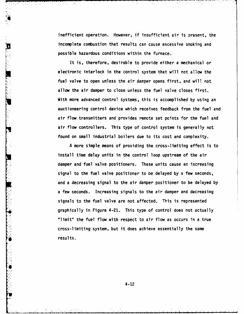
A more simple means of providing the cross-limiting effect is to
install time delay units in the control loop upstream of the air
damper and fuel valve positioners. These units cause an increasing
signal to the fuel valve positioner to be delayed by a few seconds,
*and a decreasing signal to the air damper positioner to be delayed by
a few seconds. Increasing signals to the air damper and decreasing
signals to the fuel valve are not affected. This is represented
, graphically in Figure 4-21. This type of control does not actually
"limit" the fuel flow with respect to air flow as occurs in a true
cross-limiting system, but it does achieve essentially the same
results.
4-12

h71
PUEL
MAY r~LAY
R~f-POSIS O AIR AWD. FUEL FLOWA TO A 6T1-SCHA*qF. N 5IL~r.. LPCAC WITH- TIrmE Lk FEI~

, -- . . --- . .----- - -
7
5.0 FEEDWATER CONTROL SYSTEMS
5.1 General
*] As stated in Section 2.3, the purpose of the feedwater control system
is to maintain the proper amount of water in the drum during all load
conditions. This task is complicated by the effects of drum swell or
shrink which occurs during load changes. Feedwater controls must take
into consideration the design of the boiler as well as the operating
conditions which are likely to be experienced.
Feedwater control systems are generally classified by the number
of process variables which are used in the control loop. The
variables normally used are drum level, feedwater flow, steam flow,
and steam pressure. Single-element control uses one variable,
two-element uses two variables, and so on. A discussion of one-,
two-, and three-element control is given below.
5.2 Single-Element Feedwater Control
Single-element control is the simplest and most basic type of
feedwater control. Only one process variable, namely drum level, is
used as input to the control loop. A schematic diagram for
single-element feedwater control is given in Figure 5-1.
Although there are numerous single-element control systems
available, they all follow basically the same operating principle.
Drum level is measured and transferred or transmitted to a level
controller or regulator, which in turn manipulates the feedwater
valve. As the water level lowers, the valve is opened, and as the
water rises the valve closes.
5-1

iTEAM OUT
DR.UM
FEED WATIER EL
F WAAT SLCR
0 C.OMTROL VALVE
F I L-R E 5 -1 5I LE EEMXT~~~T

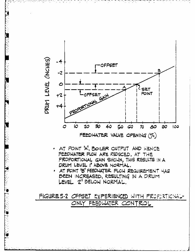
Many single-element feedwater controllers have proportional
actio only. This results in the characteristic offset experienced
with proportional control (see Section 3.5). In other words, the drum
level varies slightly as the boiler output varies. This is shown
graphically in Figure 5-2. This is acceptable in some cases, but it
is usually desirable to add an integral (or reset) function to the
control signal to reduce the offset.
Even with proportional plus reset control, single element control
systems can be somewhat unstable during sudden load changes. This is
due in large part to the effects of drum swell. Figure 5-3 shows the
response of a single-element feedwater control system with
proportional plus reset control. As load increases, swelling raises
the water level which causes the regulator to close the feedwater
valve. The reduction in feedwater flow tends to increase the steaming
rate. This produces additional swell and closes the feedwater valve
even further. Eventually the lowered feedwater flow gradually causes
the drum level to drop, and the feedwater valve then opens. The
increased feedwater flow causes a shrink, which opens the feedwater
valve even further. Finally, the rate of feedwater input exceeds the
steam flow output, which causes the water level to approach the set
point and the valve again starts to close. Continuous cycling of this
type during a load change is common with single-element feedwater
control, especially on fast steaming rate boilers.
5-2
4"
>-J-LU
F tDWATM. VALVE CPSMIN47 (%)
*AT POIN4T 'A0, 1LE CUTPUT AWDNCFeEPWArER FLOW ARE iZEiUCED. A7 T-4%.
FOOCINAL 4AIN SHCW~N, THIS RSULTS IN ADUMr LEa/EL I" A~bOV NORMAL.
*AT PCINT "5' F2a0WATZ FLOW RE Ulg 1walT HAE5EEN NCREASED, KESULTIN04 IN A L. U MLEVEL -Z" DFLOWk NCR.MAU.
FIGURE5-2 OFP5ET .YPRIEWNCED W1[7H PIZ . C~~N LY FEEL4ATfR CCNT %

* (LOQAD IKC.EASE
STiEAt- FLOWV
WATER FLOW
S- WELL
DRUM LEVEL
F16URE 53RESPONSE OF 5IN6LE-E-LEMENTFEEDW4ATER CONTROL SYST,, IEM TODlRAPI D LO/AD CHAMJ6E.
LOAD INC&EASE
STEAM FLOW
- WATER FLOW
SWELL
DRUM LEVEL
F 'RE 5-4 EStOiECETuE-LHKFE DW/ATE P COM,,TRC-ST1RAi LG AD CGHAKE.

5.3 Two-Element Feedwater Control
V When the boiler drum level cannot be properly maintained using
single-element control, a second process variable input may be added
to the control loop to improve the response of the system. This is
known as two-element control. (See Figure 5-5.) With a two-element
system, both drum level and steam flow are used to regulate the
feedwater flow into the drum. This is often necessary with boilers
that have fast steaming rates or small steam drums, or which
experience rapid load swings.
If the feedwater control valve could be relied upon to admit to
the drum only the precise amount of water required to replace the
steam flow, it would be necessary to only measure the steam flow, and
no drum level measurement would be required. This is not the case,
however, since the steam and water flows cannot be measured or
controlled that accurately. Furthermore, the feedwater flow to the
drum must also account for water lost during blowdown. Thus, the drum
level must also be included in the control loop.
With two-element control, steam flow rate is measured and
transmitted to a proportional positioning controller which compares
the flow rate to the desired set point. If any deviation exists, a
control signal is transmitted to the feedwater controller to increase
or decrease the feedwater flow. A secondary signal is also sent to
*0 the feedwater controller from the drum level controller. In effect,
the drum level controller modifies the set point or control point of
the steam-feedwater system as necessary to correct for level changes
5-3

5 EAM Fui WTRAMr FM7R
DRUM LEVELTRANMIT7rER.
,NOTE: DEEtN.DIN6 ON 714E- TYPE FEEDWATER COM-LTROLLER
USED, DRUM LEVEL WN.ORLLER;LEVEL MAY M~OT BE REQL)tRED.616NAL
cCNT~u.ER FROM LEVEL TZANSMrITTER 6OES4 CONTROLLER~
DiREC.TY TO FEEDWA~TR
FEEDWATER!Is CONTROLLER,
FW VALVEIFEEDBACK< ipc5il I OWER
FEEDWATER
V/ALVE
F1J RE 5-5T.OE~ET ED~A?

resulting from unequal steam and feedwater flows. For example, when
the load increases, the steam flow transmitter and control system
respond to increase feedwater flow. This, in effect, anticipates the
change in water level. It also counteracts the tendency of the drum
level element to close the feedwater valve as swell occurs. Thus,
both the feedwater flow and the drum water level are quickly
stabilized, even if the change in load is rapid or large. A
two-element system provides sufficient reduction in the sensitivity of
the feedwater level controller so as to disregard the normal effects
of shrink or swell.
5.4 Three-Element Feedwater Control
When operating conditions are severe, the three-element control
system is by far the most reliable for maintaining drum level within
the desired limits. With three-element control, the feedwater flow is
*measured in addition to steam flow (or pressure) and drum level (see
Figure 5-6). This provides a closed-control loop in the system which
is not available with either one or two-element control. With both
one and two-element control, the feedwater valve positioning is
* open-loop. Actual flow is not measured, and the feedback to the
* .. control loop which corrects the valve positioning comes from drum
level only.
In a three-element control system, the feedwater flow is
measured, and a feedback signal is produced which adjusts the output
signal from the feedwater controller. This direct feedback insures
5-4
0 ..

that the desired feedwater flow is quickly achieved despite variations
in water pressure or water temperature, changes in valve
characteristics, loose linkages, or other system deviations.
Three-element control reduces the sensitivity of the drum level
controller below that achievable with two-element systems, which makes
them virtually unaffected by drum level instability. Three-element
systems can also make effective use of proportional-plus-reset
functions in the feedwater controller, thus eliminating droop (or
offset). Figure 5-4 is a graphic representation of the response of a
three-element control system to a sudden change in boiler load. As
can be seen from this diagram, the feedwater flow is increased quickly
after load increase, even though the apparent drum level has increased
due to swell. The feedwater flow also quickly stabilizes despite
several fluctuations in drum level. The drum level returns to its
original position (with no offset) even though the boiler output has
increased.
Three element control systems are also available which measure
steam pressure (instead of flow), drum level, and feedwater flow.
Although this approach is somewhat less common, it, too, provides
precise control. The functioning of this type system is essentially
the same as that outlined above, the only difference being the fact
that steam header pressure instead of flow is monitored.
5-5

-~ ~ 5, EA
DRUM i..EVELThRANS M rflE R
TRAN~SM i-TTERt
;CONTOLLER
-- w f=EEDWA7ER' CONTROLLER'
t,4OTS: DEPEWDIKI~ ON-T4E 7YE PEEDWA7E&.C.ow -Rcl 1ER USED, DRULEVEL CON TROLLER MAN(~4o7 i BE EQuiPED. i14AL
FROM LEVEL TRANSMIT7ER 5IG N AL.0E iRECTLf IT
F=EEDWATER CONTROLLER.
FEEDWATER
\/A LV
ItUR I:HK - Z ,T:

5.5 Mechanical Feedwater Regulators
Mechanical feedwater regulators provide a complete control
*i system, from drum level sensing to feedwater valve positioning. They
generally provided single-element control, but two-element control
regulators are also available. In either case, the entire control
process is accomplished mechanically, and electronic or pneumatic
control elements are not required.
Mechanical regulators have generally been replaced through the
years with electronic or pneumatic systems like those described
earlier. However, many of these regulators are still in existence and
some types are still being installed on small boilers today. Two of
the more common types of mechanical feedwater regulators are discussed
below.
A thermo-hydraulic, or generator-diaphragm type of feedwater
regulator is shown in Figure 5-7. This regulator uses the increase in
pressure caused by evaporating water within a confined space to
position the feedwater control valve.
The water is evaporated in a "generator" which consists of two
concentric tubes. As can be seen from Figure 5-7, the outer tube of
the generator is connected to the valve diaphragm chamber, which in
turn positions the feedwater valve. The diaphragm, connecting tubing,
and the outer tube of the generator filled with water. The water does
not circulate, and heat is radiated from it by fins located on the
generator. The inner tube is connected directly to the water column
and contains boiler water and steam. The water in the inner tube
remains at the same level as that in the drum.
5-6

DRUM1
NO~RMAL W4ATER LEV L ___
FINS
FEEDWATERleE-qULATlNq
VALIV F
0 ~5ILg ~EWAR
4,
~:~J~501L T iJ44ATh UICR A
.6 COH TKOL

When the water in the drum is lowered, more of the inner
generator tube is filled with steam. Since heat is transferred faster
from steam to water than from water to water, extra heat is added to
the confined water in the outer generator tube. The radiating fin
surface is not sufficient to remove the heat as rapidly as it is
generated. The heat from the steam in that portion of the tube
vacated by the drop in water level thus causes the water in the outer
tube to flash into steam. This increases the pressure in the outer
tube which, in turn, causes the bellows in the valve positioner to
expand. This forces the valve to open and admit more water to the
drum. When the drum level is raised, the above process is reversed.
A thermostatic expansion tube regulator is shown in Figure 5-8.
This type of regulator uses the expansion and contraction of a
thermostatic tube to position the feedwater control valve.
As can be seen in the diagram, lowering the drum level causes more of the
thermostatic tube to be filled with steam. Since heat from the steam
is transferred to the tube faster than the heat can be radiated from
it, the tube expands. This causes displacement of the feedwater valve
linkage and the valve is opened. When the water level rises, the
process is reversed.
5
5-7
.-

DRU -,--AN-w-W . -
NOR N -1AL jWIAi! :Vg
FEeDWATERCONTRCL VALVE.
HGU<E 5.& ThRHOTATIC ~~:i3
E~4A~h~ ULATO

6.0 FLAME SAFETY SYSTEMS
6.1 General
The purpose of the flame safety system is to prevent explosions
that can occur when: (1) a flame or other ignition source is
introduced into a furnace that contains air and fuel vapors in an
explosive mixture, (2) fuel is discharged into the furnace during
start-up without proper ignition taking place, (3) the burner flame is
extinguished during normal operation without the fuel supply being
shut off; or, (4) a major malfunction in the burner or feedwater
control system occurs. There are a number of control techniques
available, and the various manufacturer all have their own
preferences, but each flame safety system provides protection in the
areas outlined above.
In contrast to the sections covering burner and feedwater
controls, no attempt will be made here to identify all the control
components in the flame safety system. Instead, the basic functions
of the system will be examined during each of three operating modes:
start-up, normal operation, and shut-down will be discussed. The
reason for this approach is the fact that flame safety systems are
generally not discrete systems. Rather, they are a series of timers,
relays, limit switches, sensing devices, etc., which are integrated
into the burner control system to provide the necessary interlocks.
Although totally automatic systems are available, only
semi-automatic or "supervised manual" systems will be discussed here.
The more advanced systems are generally not found on small industrial
boilers and are, therefore, considered beyond the scope of this text.
6-1

6.2 Start-Up
Start-up from a cold condition presents perhaps the greatest
danger from explosion. It is essential that the furnace be purged of
all combustible gases before any source of ignition is introduced, and
that once fuel flow is initiated, ignition takes place quickly.
The entire startup process may be controlled automatically, but
most small industrial boilers are started either manually or
semi-automatically. If a manual-only system is provided, few
interlocks may exist other than those which prevent lighting the
ignitor after the fuel valve to the main burner has been opened.
Semi-automatic systems provide a much greater level of protection
against improper operation and are obviously more complex. The
interlocks provided by a semi-automatic (supervised manual) flame
safety system during the start-up process are shown in Tables 6-1 and
6-2.
Purging of the furnace is generally accomplished using the
combustion air fan(s). A purging air timer is provided that will not
allow ignition until the fan(s) have been in operation for a specific
period of time. For watertube boilers the purge air flow must be at
least 70 percent of the air flow required at the maximum capacity of
the boiler, and the duration of the purge must be sufficient for at
least eight air changes to occur. (This is usually around 5 minutes).
For firetube boilers, the purge is conducted with wide open dampers,
and four air changes are normally required. In either case, air flow
is verified by providing limit switches on the dampers and a pressure
switch at the fan discharge, or by providing air flow measurement
devices such as differential pressure switches.
6-2

Once fuel flow has been initiated to the ignitor or main burner,
flame verification is usally achieved by means of flame scanning
devices. These flame scanners may be either the infrared flicker type
or the ultraviolet type. (See Section 7.3.1).
I6
-6-
-----------------.

' TABLE 6-1
FLAME SAFETY SYSTEMTYPICAL PREFIRING CYCLE
Operator Function Flame Safety System Function
1. Check to see that fuel Verify fuel shut-off
shut-off valve is closed, valve is closed.
2. Start fan. Verify fan is on.
3. Where used, open atomizing Verify atomizing mediummedium valve, supply is available.
4. Open damper(s) to purge Verify air pressure isposition. available and
damper(s) is open orverify air flow.
5. Start purge timer. Verify purge time haselapsed.
6. Place damper and fuel Verify damper and fuelcontrol valve in light-off control valve inposition. light-off position.
If light-off air flow isless than purge air flow,start light-off timelimit timer.
7. None Verify spark and igniterand main safety valve isoperable.
4
io

• -~ ~ . . . ". .
TABLE 6-2
FLAME SAFETY SYSTEM. TYPICAL LIGHT-OFF CYCLE
Operator Function Flame Safety System FunctionI.1. Start igniter ignition Verify igniter operation.
system. If air flow is less thanpurge air flow rate,igniter operation shallbe demonstratedwithin 10 seconds.
2. Open fuel safety shutoff Nonevalve to main burner.
3. Open manual fuel shutoff Verify flame within 10valve. seconds for gas,
No. 2, and No. 4 oil, 15seconds for No.5 and No. 6 oil. Closeigniter safetyshutoff valve(s). Forgas igniter ventgas piping betweenshutoff valves.
4. Bring unit to preset Noneoperating pressure atacceptable rateand switch to automaticcombustion control.

.. °
6.3 Normal Operation
The main safety hazard during normal operation is loss of the
burner flame. This can result form a variety of causes, including
improper fuel pressure, interruption in fuel supply, contaminated fuel
(with water, sludge, etc.) boiler tube rupture or some malfunction of
the burner itself. If the burner controls are improperly calibrated,
the flame can be unstable due to improper air fuel ratio.
The flame safety system must, therefore, ensure that the fuel
supply to the burner is shut off immediately whenever the burner flame
is lost. This is accomplished using the same flame scanners that are
used for start-up. If more than one burner is provided, a flame
scanner is usually furnished for each burner. If the burner flame
goes out inadvertantly, the flame scanner immediately trips the fuel
safety shutoff valve.
The flame safety system must also have the ability to take the
boiler out of service if a major malfunction in the burner control
system or feedwater control system occurs. Therefore,
interconnections are usually provided between the flame safety system
and both the burner control and feedwater control systems. These
interconnections allow the flame safety system to trip the boiler
any time one of the following conditions occur:
1. Loss of burner control system power (electric, pneumatic, orhydraulic)
4 2. Loss of combustion air supply3. Excessive steam pressure4. Loss of atomizing medium (if required)5. Very high or very low drum level6. Improper fuel supply pressure
6-4I'
If the boiler is furnished with sootbiowers, interlocks are
normally provided so that sootblowing can only be performed when the
boiler is in service with a firing rate sufficient to avoid
extinguishing the burner flame. Sootbiowing during shutdown or
startup is thus precluded.
6.4 Shutdown
The flame safety system is involved in both the normal boiler
shutdown and the emergency or safety shutdown. (The normal shutdown
is one which is initiated by the boiler operator, whereas the
emergency shutdown is initiated by the flame safety system or by any
boiler trip signal.)
During a normal shutdown, the flame safety system verifies that
the fuel safety shutoff valve to the main burner is closed so that the
combustion air fan and atomizing system (if used) may be shut down.
In an emergency shutdown, the flame safety system will normally stop
the fuel supply to the main burner and the igniter (by tripping the
safety shutoff valves) and interrupt the spark to the igniter. If a
gas burner and/or igniter is used, the flame safety system will also
vent the piping between the fuel safety shutoff valves during an
emergency shutdown.
6-5

7.0 CONTROL SYSTEM COMPONENTS
7.1 Burner Controls
7.1.1 Manual/Auto Control Station
Function
The manual/auto control station allows the operator to isolate a
device or sub-system from automatic control and to operate that device
or sub-system manually from the control station.
Theory of Operation
o Pneumatic Systems
In the automatic mode of operation, the output signal from the
manual/auto control station is identical to the input signal. An
unrestricted passage is provided through the device so that the air
pressure at the outlet signal port is the same as the air pressure at the
inlet. In other words, the manual/auto control station has no effect on
the system when it is in the automatic mode.
In the manual mode of operation, the output signal is totally
indepdendent of the input signal. The input pressure signal is blocked by
means of a multiport valve, and the output pressure signal is controlled by
manually adjusting a pressure regulator. This regulator is fed from an
auxiliary air supply (from the instrument air compressor).
An important feature of the manual/auto control station is what is
called "bumpless transfer." That is, the ability to switch back and forth
from manual to auto without drastic or rapid changes in the output pressure
*4 signal. Indicating gauges are provided on the control station, and the
valving arrangement is such that the output signal may be manually adjusted
to match the input signal before the transfer is made.
4 7-1

o Electronic Systems
The electronic manual/auto control stations operate in the same manner
as the pneumatic units, except that electronic circuitry is utilized
instead of mechanical components. The input signal can be duplicated as
output (auto mode), or the input signal can be blocked and an independent
output signal generated by the unit (manual mode).
7-
7-2

I 2I -ify Babcock&Wilcox Product SpecificationI
BAILEY 7000 M/A STATIONType 711
Function
Provides a means of c.onneccing a final control element
either it) in automaticsig~nal.d atit manually adjwalble M/A STATIONmanual control is bunspiess. _____________________
The station nay be equipped with in optional inputmeter.
Application
The Type '1 N13auliAutomatie Station is usedprinmarily wltere one zontroiler actuates several fitnal cosntrolelements and it may ble desirable to switch any element fromautomatic to manual control.
Description
The Type 711 Manual. Automatic Station is provided witlsat output meter with ascale calibrated 0-100 per cent. The
* meter is equipped with a manually adjustable pointer on thleoutside iof wie case. This memory pointer alows tile operator
* to -nark thle station output tor normal operation.
Operation
Whlen the station rnanuali automa tic switch is in 'ht11utomnatic position the 1-5 volt unput Produce$ two Output;igitais. 1-5 volts and 4a- DC
When the SI/A switch is in the manual positions. the ! 0 0 60 so wstatilln output is derived trom a pusabutian actuated mnanual 4 0 8 0power supply. Interchangeable caps on thle pushbuttons.marked "Close .' and "Open". indicate tile state or the ;inal
*controtl element XorreSplinding to 0 and 1001, output. WhenI*normal pressure is applied to a pushbutton, the station output
citasiges it a raie that takes 50 ,econds tor !00 per :.cntAcaine. If dhe button is pressed itard against the stop, the
mutput change is 100 per cent in 4 seconds.
to decrease, however, thle direction of chaite can be reversed'~revosittoiting jumpers on tile circuit board.
There :s nso isige in outotut when the station is switcihedr;,t idiomatic to manual.
%lhienti Ire station is switchied trout ianiual to automaticthere is no immediate )utput chante. If. however, the manuil FULL SIZEjutput is not the same as the automatic signai at !he time ittratisier. the station output will ramp to the proper value at an FIGURE TveI I N1A Stationadiuiiable rate or~ 0.30 seconids for a 10' change.
FIGURE 7-1 BAILEY ELECTRONIC MANUAL/AUTO STATION

Bailley abcok&Wicox Product Specification
MINPILINE* 500 HAND/AUTOMATIC STATION
SERVICE
Providle% all necesaary indica- _______________________________________
tion* anti controls for smooth.*in l i and automatic+
transfer anti complete remoteumanulal ur jutoniatiC operationof a pneumatic control y~stem.AUT _H N
Application ~For uae as a *incle-loopv or .. I
multi-loop pneuma tic control '100 0Ay-tmft comnentflf or as an in iidependent operatnt station r- N -E %tion. E R.- 0
a Small size anti compact group-*-6*- 0lug of all indicators and controlknol,. provide maximtum effi.
-icey anti flexibility in layout R40 -4of control -titions. -
- A-Plu-in module design per. -' - N- -
muit, removal of H A 4tat ion 0 -20 s. 2without *isturhing pipins since I.Eall connections are made at Nmanifold on rear of protective T* ~ 0soc~ which mount# directly to
9 lfeduce!s routine mtainltenance Nthrough use of bitilt-in air 4up-*,1 ilternd, ltain eisa
e Simplifie.. stockintg of -.pare -parto -illre uuanyv of tile .op.n.cnt part. are couinon to otherBaile% cqnlipument.
FIGURI I - MINNUNI SOC0I' HI~~NA Station, TYPE AJ. 1 ULSZ
Nov,. U.S. Pat. 04.
FIGURE 7-2 BAILEY PNEUMATIC MANUAL/AUTO STATION

ale Babcock&Wilcox Product Specification I= =Bftel Bbcoc&WicoxE91-712
BAILEY 7000 BIAS M/A STATIONType 712
Function BIAS M/A STATIONThe Type 71Z Bias Manual/Automatic Station accepts an
input signal and either adds to it. or subtracts from it a fizedamount up to 25% of the input span. After this addition orsubtraction, the signal is passed on to the load if the station,,anual/automaic switch is in the automatic position. .
If the switch is on manual. Ehe load is supplied with either1-S volts or 4-0ma from an independent supply within the -station.
" IApplication
Figure 2 illustrates a typical application of the Type 712
Bias M/A Station. Header pressure is controlled by a pressurecontroller, the output of which regulates flow of coal fromthree pulverizers to a boiler. 10
For the same control signal the pulverizers do not deliverthe same quantity of fuel to the combustion chamber, and ifthe pulverizersdo not divide the load equally, they may causethe operation to be inefficient.
Tie bias stations make it possible to balance thepulverizer autputs so that they respond equally to the pressurecontroller output.
Description 0 4O 40 60 80 100
The Type "12 Bias Manual/Automatic Station consists ofa front panel on which are mounted dhe bias settingmehanism. meters. manual operation pushbuttons andtwo-position transfer switch. The vertical meter is a I.5vvoltmeter scaled 0-ICO representing percent of the nput Mvanal-le. The horizontal meter is scaled 0-100 :evresentt!gpercent of the station output wihich may be either 1-5 volt or4-.0ma.
The electronic elements. which are a combination i:nelated circuts. amplifiers, and liscrete :omponents. aremounted un a single .llaas epoxy laminated circuit board.
The top and bottom of the :ontroller are extrudedaluminum, and an easily removed cover plate on each sidecompletes the enclosure.
FULL SIZEA spring ,;arch on the too secures ile station in its normal
positiun on tle itieif ut allows eas., withdrawal, either FIGURE I • Tyue 71. Bias Manual, Automatic Station.,completely or half.way. for n-place calibration.
FIGURE 7-3 BAILEY ELECTRONIC MANUAL/AUTO STATION WITH BIAS CONTROL

Hy-Republic
model C-04330pneumatic control stations
9 MANUAL or MANUAL-AUTOMATIC o CONSOLE ORIENTED*
0S UMPLESS M/A TRANSFER 0 MiNiMUM PANEL SPACE0
oerat ionThe Hays-Republic series of pneumatic control stations
ore available in seven variations for such applicationsas: remote set point; manual-uto transfer of panel orremotely located controllers; manual-uto stations for spec ifi catieonsspring set point or cascaded controllers; monitoring andremote positioning of final drive devices; and stations Model............................. C-04330
formoitoin ony.Input/Output....................... 3 to IS psigThe control stations feature a 3-inch duplex scale indl- Indicator
cating the controller variable with either the final control Acrc............ ~o agor set point pressure. All controls and switche, are readily Sensitivity....................±!1 /2% of Rangeiaccessible on the front of the compact panel. There is Red Painter.................. Manual Loadingno moed for bock-of-the-pane4i adjustments, or special Black Pointer................ 3 to 15 psig Inputsetting procedures. Air Supply .. .. ........ I18 to 20 psigl
Basik elements for each s-ation include a hand loader Static Air Consumption........... ...... 0. 1 scfmfar quick set point adjustments when the system is on Service Markings..................... 25 spacesautomatic; or loading a final control element during Panel Cotout............... .... 2-3/A* w x 5" himanual operation. Manual-auto models contain transfer Weight......................... 6 Pounds Netvalves providing positive, bumpiest inta transfer. modelsC-4301 and C-A3304 include a position switch f or set
0 ioint loading pressure and controlled variable tyn-
chranizatian.
FIGURE 7-4 HAYS-REPUBLIC ELECTRON IC MANUAL/AUTO STATION

Hays-Republic
model C-85001hand auto station
e, SIMPLE RUGGED DESIGN 9 PRECISE MANUAL POWER UNIT POSITIONING .
S CONVENIENT FRONT ADJUSTED ZERO AND SPAN e
"T2"
4
application constructiboThe C-85001 Hand-Auto Station permits re- The C-85001 Hand-Auto Station incorporatesmote or rear of panel mounting of 840 series the conventional two-position hand-auto switchcontrollers while providing the necessary with separate "open' and "close' push buttonmanual functions and position indication (op- switches. Optional is an electrical indicatortional) to the operator. Mounting of 840 con- showing the position of the power unit manip-trailers at locations other than the front of the ulated by the 840 controller and the Hand.panel makes greater panel area available Auto Station. A 500 ohm slidewire is requiredfor items which are necessary there. If de- on the power unit to operate the positionsired, the C-85001 Hand-Auto Station may indicator. Energy for the position indicatorbe located on sloping panels or bench boards, circuit is supplied by a small stepdown trons-a location not permissible for the 840 con- former supplied as an integral part of thetroller. Hand-Auto Station. Indicator span adjustment
Controllers of the 840 series which may be is accessible from the front of the panel.
used with the C-85001 Hand-Auto Station inthis manner are C-84105 Sequence Draft Con-troller, C.84106 and C-84107 Draft Control.lers and the C-84601 Electric Positioning Con-troller.
FIGURE 7-5 HAYS-REPUBLIC PNEUMATIC MANUAL/AUTO STATION

7.1.2 Air/Fuel Ratio Relay
Function
The air/fuel ratio relay is a manual/auto control station that
provides an output signal which is proportional to the input signal in
the automatic mode.
Theory of Operation
o Pneumatic Systems
A typical ratio relay station uses a "seesaw" type beam
arrangement to balance the output signal against the input signal.
The input pressure acts through a diaphragm to rotate the beam in one
direction, while the output pressure acts through a diaphragm to
rotate the beam in the opposite direction. The beam is connected to
the output pressure regulator valve such that movement of the beam
causes either an increase or decrease in the output signal. Air for
the output signal is furnished by a constant pressure air supply to
the regulator from the instrument air system.
The ratio relay station may be operated in either the automatic or
manual mode. In the automatic mode of operation, the output signal is
always directly proportional to the input signal. However, the ratio of
output to input pressure may be varied by a manual adjustment which changes
the location of the fulcrum under the balance beam.
7-3

77" -7
In the manual mode of operation, the output signal is totally
independent of the input signal. The input pressure signal is blocked by
means of a multiport valve, and the output signal is controlled by the same
manual adjustment which is used to vary the output pressure ratio during
automatic operation. In effect, a constant pressure signal is substituted
for the input pressure signals, and the operative of the device is
otherwise the same as for automatic operation.
As with standard manual/auto control station, the ratio relay station
must be capable of "bumpless" transfer. This is accomplished in
essentially the same manner as was described for the manual/auto
station. (See Section 7.1.1)
o Electric Systems
The electronic air/fuel ratio relay functions in the same manner as
the pneumatic unit, except that electronic circuitry is used in lieu of
mechanical components. In the automatic mode, the output current signal
varies from the input signal by fixed ratio which is determined by the
plant operator. In the manual mode of operation (if available) the input
signal is blocked and an output signal is generated by the relay unit.
With some systems, a pure manual function is not provided. However, the
output signal can be varied at any time by the plant operator by regulating
the bias adjustment.
7-4
1

Hays-Republicmodel 845:O01B
fuel-air ratio controller*FAST, EFFICIENT ELECTRICAL CONTROL o
0 .IANVJAL/AUTOMATIC CONTROL STATION * LOW LOAD RATIO ADJUSTMENT 9
APPLICATION This tyeo otolrhssvrl the pilot device to close the contact in one of the nmere.uss su ; a Maintaining 11) a urv switches. This energises the power unit to increase
ratio of combustion air flow to or'decrease the controlIled air flow until the cotrectflow of fuel, 12 a proportioned flow of two gases. proportion of Iss to air is estabslishied.and 13) an established differential of two pressures.two drafts, a pressure and a draft, or one flow and Model 845:04&B is used to control forced draft faneither a pressure or a draft, speed.
OPERTION Fieure I illustrates use of the con.
to another, such as sir flow to gas__________Rlow. The upper differential diaphragm unit is con.Lnected across a differential device -orifice, venturi.etc.)I in a gas pipe or duct. The flow through this pipeis autoinatically or manually controlled by separate ._ .......
means and the differential produced is the loadingforce on the controller. The force is transmittedthrough linkage to the lower differential diaphragmnwhich' is connected across 3 differential installation in ~.,~an air line. The air Rlow differential is thus balanced -
against the gas flow differential. When the sir flow is- -
taut in correct proportion to gas Row. the diaphragmmnoves and connecting linkage causes the armature of 11guV.e I
67
FIGURE 7.6 HAYS-REPUBLIC PNEUMATIC AIR/FUEL RATIO RELAY

APPLICATION agstol LThe Model 89.02 Ratio Set Station is used to ratio one Q 4process variable to another proc.. variable. The versa-rility of the ratio station allows it to be applied to many -"operations. In ~o applications the signal (i-5 me d-c) -from a transmitter is fed into the ratiostatlan. This instn- Mo=
emeet reflects fth desired ratio aid bins into its output. v6The 895:02 isdaignedprimwily, although not exclusively,for uwewith Hay"MadoisS54nd855 Universal Controlers.
A typical flow Transmitter has a 1-5 ma S-c output repre-
* senting 0-100% of the transmitter range. Assuming range RAg Sof the transmitter to be 0 to 120 gpm, a 30 gpm flow willbe represeted by a 25% output signal from the tranmitter. +If the ratio is set at unity, the output of the 895:02 Ratio
Set Station will be 25% ar 2 r d-c. t'owevn, if theratio is set at two, the output will be 50% or 3 me d-c. H1IIlu~oated below an twoypical applications of the Hays895:02. in he Fiat, Far exaple, the ratio station iscontrolling the set point of a Model 8W contrioller. As J _"
the rafte of flow of the poc variable (PVI) increases,te set point of the contullerisreadiustedso th the rateo/fflow of PV increaseina prperIon determied by theratio dial seting.
Ie 002 Pr aie Set Satieson, curren output. Vertices alendiceerds*o ea tof the Storin pae atF iei signel.
1 T1wred i 22A TRAN5MITTER 0 ,.pi. Imn -
iew ft " twis of PV1), gtoWjp iv
2 IOwa SJFIfY "m O
3t j3 I95,0 RATIO STATIOrN-wS 5 00
- 4 CONTROER.
S t2S2A FttSml..meto iowr "e .€ lw i. twoo eiuin 0.
6 CONTROL VALVE Mf swn 9*-m 0 dai ,a cte.
I r. -0l 232A tPASilNti swe aqMo we,
2 POwER SU .sY .t
__ _ _s _ _ _ 1 3 M:02 RA tIO STArON wI IF aw"fl.4.1 4 W CONTROLLE Atch Ow ca.iw e int a,
5 CONTROL VALVE.
3 : 6 A MMes g-0d US CONROLLISa ER s
? 23A TRANMfTER w.I CONTROL VALVE " eawintI% M9 e PV, We.-
7tfl ft..cemsW fog ed -" . WI6, W i .
FIGURE 7-7y *.nRsBty E C R N RATO E
"..'FIGURE 7-7 HAYS-REPUBLIC ELECTRONIC RATIO RELAY
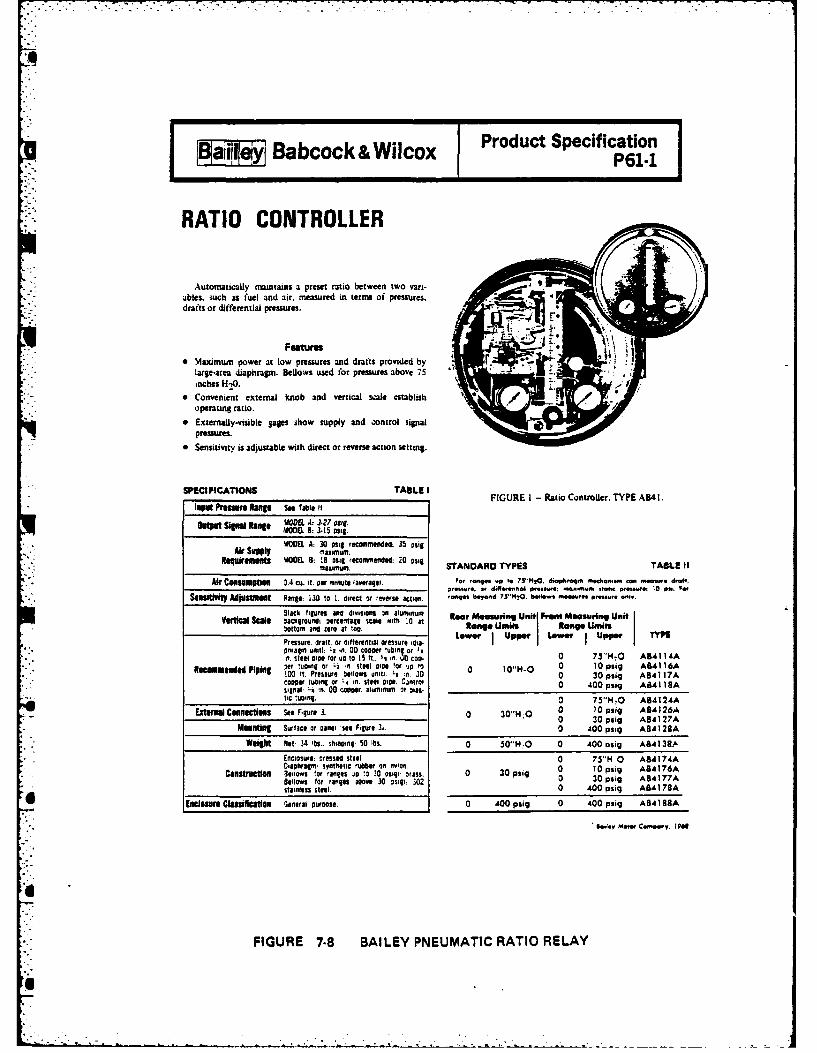
Babcock&Wilcox Product SpecificationaijietyP61-1
RATIO CONTROLLER
Automatically maintains a preset ratio between two vari-ables. such as fuel and air. mneasured in terns of pressures.drafts or differential pressures.
Features* Maximsum power at low pressures and drafts provided by r.
large-area diaphragm. Bellows used for pressures above 75 7.U
inches H-4.
* Convenient external knob and vertical sc.ale establish / moperating ratio.
* Externally-visible Sges show supply and control signalpressures.
0 Sensitivity is adustble with direct or reverse action setting.
SPECFICTION TALEIFIGURE 1 Ratio Controller. TYPE AB4 1.IOWt Pressre Rane See Table It
cowu Signal Rang' MOE l. 3-15osgYOVDEL A: 30 osig recnmiemilde 35 osig
Air SWppY Maximnum. I
* ~~~Requireueot YOD0EL 8: 18 sg recommended. 20 osig SANAD YESALEI
Air Cossuurptaon 0.4 cu. ft. Per minute taveragel. Far-9 *.0~ 19 1 5M420. dieniin. eche~wi w cmi- ,or.r~v. edifltrfol P-iurii; '?sm . rant rnwn, 1es P.. e
S4111111"t AdIUSIUt Range: 130 to 1. direct itr~eers. action. .mnbey.d 73-1020. bnilkw -ft.en iirilmm.
Slack figures and divisiosn a luinum Rear MenngUieFedMauigUiVerlnal Seals 3acfltrnund: "eteentage scale with .0 at Ra n o? Uni I Rae Unit
bottom and zero at too. Iin e t a"Unf
Prssre daf. r iferntalorssr;t. LOWer Iup". ILOWer I UPPer j wilonragmn unit)m L2 in. 00 cooner *ubin or isft. Steil 01011e for sUb to5 ft.. i n. Csoo 0 75"M4.0 AB41 I AA
Pipinmgd "r tuning 0r Li in steel Mooe 'Or 'Jo to 0 10 psug ABA4116Arpfg 0 t.Pesure bellows unit). II !n. 00 0 30 psig ABA) 17A
copper tubing or 1. on. steel sinle. Cantrol 0 400 psig A8A lI 1Asignal: 1i an. 00 Cooper. sluiieeut or osmtic tubing. 0 75"lI.O A84124A
Extmrnal Caenels See figure 3. 0 30"M-0 a 10 ps;g ABA I26A0 30 psig AB4127A
Meig" Surface or Carei see Figure 31. 0 4100 posig ASA128A
Weigt Not- 34 IbS.. shliocel 50 lbis. 0 50'i4~O 0 400 asig ABA138P.Enciosure: cretssd steel0 Sl0 AAIADiIIUU Oahrag. synthetic rubber on ior. 0 0pu 10 pFiq A64176A
stainless stee. 3 [g 0 0 400 puig A84178A
Eneissure Classifleatien General oureele. 0 400 puig 0 400 plig ABA188AA
11C.4lv Moiw Cuine n. I plu
FIGURE 7-8 BAILEY PNEUMATIC RATIO RELAY

aiieyi Babcock &Wilcox Product Specification-,B y .o E91-715
BAILEY 7000 RATIO STATIONType 715 RATIO STATION
Function
The Type 7 15 Ratio Station is used to multiply an inputsignal by a manually adjusted factor to produce an outputsignal that is at the set ratio to the input. -
The output of the station can be used to adjust the -0 .cascade set point of a controller. maintaining a desired ratiobetween two process variables. -C
Application
In ratio control. Figure 2. of a controlled variable (flowA) to an uncontrolled variable (flow B) the measurement 40signal from tlow B is applied to the input of the ratio station. -
The ratio station multiples this signal by an adjustable =20factor. preset on the set point scale, and transmits the output -as a set point icascade input) signal to the flow controller.
The flow controller continuously retulates flow A inproportion to flow B at the ratio setting. The signals of bothflows in the example have a squared relationship to flow rate.
If one was squared. i.e.. Idifferential pressure) and theother linear I magnetic tlow meter). t would be necessary tolinearize the squared signal with a Type 750 Square RootExtractor.
For applications where it i desirable to have the station III iI IIHI' I!IIIoutput biased so that the output will be above the minimum 0 '20 '40 60 so 10I1 volt or 4ma) even though the input is reduced to theminimum value of its range, the ratio station has a circuitboard adjustment that makes it easy to bias the output so itnever rails below some desired value W0-50%) of output spaneven though the station :nput fails to zero percent.
Operation
The input meter indicates the input n percent beforerrtioing. The signal then goes to the set point ilidewire andgain amplifier which subtracts the I-volt live zero andmultiplies the remaining signal by the tactor set on the setpoint scale. An output bias is added to the ratioed signal.available at the station output as a 1.5 volt andior 4-Omasignal.
Features* Input and output meters for visual companson of ratio. FULL SIZE* High accuracy ratio set 3oint on a O-inch scae.
" Adjustable output bias. FIGURE I - Type ' 5 Ratio Station.
* Both 4-2Oma and 1-5v output.* Wide or narrow ratio spans, linear or square root Optional Features
0 Input.output test jacks. * Indicating lights , operated from external contacts.* DC to DC power supply isolation. 0 l.Hertz filter- for exceptionally noisy processes.
i'. Sawv Mete," Camoany 1974
FIGURE 7-9 BAILEY ELECTRONIC RATIO RELAY
q-

7.1.3 Master Pressure Controller
Function
The master pressure controller compares the steam header pressure
with the desired set point and produces an output signal which is a
function of the deviation (error) between the header pressure and the
set point.
Theory of Operation
o Pneumatic Systems
The master pressure controller uses a lever and fulcrum arrangement to
balance output signal pressure against steam header pressure. (If a
pressure transmitter is included in the control system, the input to the
master pressure controller will be a pneumatic signal. Some units can
utilize steam header pressure directly as the input signal.) The steam
header pressure acts, through a sealed bellows, to rotate the lever in one
direction, while the output pressure acts through a bellows to rotate the
lever in the opposite direction. The lever is connected to the output
pressure regulator which in turn controls the output pressure signdl.
Therefore, displacement of the lever causes either an increase or decrease
in the output pressure signal which tends tn restore the lever back to its
original position. Air for the output pressure signal is furnished by a
constant pressure air supply to the controller from the instrument air
system.
7-5

0 Electronic Systems
A typical electronic master pressure controller utilizes a
magnetic amplifier which sums the various input signals and determines
the magnitude of the error signal. This error signal is then
* amplified and transmitted as an output signal.
A feedback loop is provided from the controller output back to
the input. The purpose of this feedback loop is to adjust the output
signal so that the most desirable response to a given error signal will
result. The feedback loop typically contains proportional, reset
(integral), and rate (derivative) funco.-ons. The proportional function
provides an output that is directly proportional to the magnitude of the
error signal; the reset function provides an output that is proportional to
the integral of the error signal; and the rate function provides an
output that is proportional to the rate of change of the error signal.
By summning the input signal and the various feedback function signals
and comparing them to the set point, the master pressure controller
produces an output signal that tends to return the steam pressure to
the desired set point with a minimum of pressure swings.
7-6

D 612 68 BOILER CONTROL SYSTEMS THEORY OF OPERATION NANUAL(U) 2/2ULTRASYSTENS INC IRVINE CA FEB 83 NCEL-CR-83. 613N624?4-Bi-C-9388
UNLSSIFIED F/G 13/1 NL
mhhhhhhhhhhhEE.NONNI flflfl lf..fflffl
Eh~hhFE

,7 - -
-1 . ... -
-ii
. II '=_-° ,
1.&2ma 1I1"o
L
111162 1. 4 H
MICROCOPY RE§OLUTION TEST CHART A
NATIONAL BUREAU OF STANOARS-1963-A
1" ' "

Hays-Republicmodel 841 :02B
master pressure controllera MANUAL/AUTOMATIC CONTROL STATION.9 FAST, EFFICIENT ELECTRICAL CONTROL.a
*ADJUSTABLE SET POINT. METALLIC BELLOWS MEASURING ELEMENT.FOR PRESSURES TOJ 300 PSIG.9
APPLICATION Model 341:023 Master Controller is A change in thr 'train hrtadker pressure 'due to ana primary controlling unit of the increase or decrase iii feanith li. acts an the metallic
Hays lectric Combustion Conttol System. It responds bellows causiou ,mitart t.. be tidl.. i-mi -,fii the mer.to change in steam pressure and adjust the rate of cury switches. lii, ,.orwiss the toa,.tr oiotor whichfuel or air supply accordingly in order to maintain loads -'ther u.,mtrll..r, thr-uhl Nossing or -ending po.uniforn steam pressure. It maintains a uniform pres teritiite". Fuel jod. %ir t:.,tr,,lht-rs then change thesure over the entire range of boiler operation. This fuel flow and air fl,.w t,, bringi the. stvani pressure backcontroller is used with pressures to and including 30Dj to the set Point.Psi. The follow-up linkage shown is connected to the mas-
ter motor on the rear 4f the controller bv means of ashaft. This shaft extends to the inside of the case andis connected to the mactiet bar. Movement 4~ the lever
OPIIATON Model 341:028 controller directly breaks the contact in the mercurv switch. stopping thereulte te aeAf ue adNi power unit. No further chance takes place until the
suply through an integrally mounted master motor. -ta hedrpsueagivre.Thspower unit is cu,nnetutrmj through linkage to the One Master Controller of this tipe and one power
fuel and air cositrollers. This po-wer unit can- also ad. unit can control the rate of fuel and air to several steamjust sending puuteiutiu,.eters for remotely tmounted c'nn generators providing they all deliver stean to the sametrIlers. See Figure 1. eader.
FIGURE 7-10 HAYS-REPUBLIC PNEUMATIC MASTER PRESSURE CONTROLLER

1.2 Feedwater Controls
7.2.1 Feedwater Controller (Electric and Pneumatic)
Function
The feedwater controller regulates water flow to the steam drum
in accordance with (1) drum level, or, (2) drum level and steam flow
*orr pressure requirements.
Theory of Operation
0 Single-Element Controller
The single element feedwater controller has only one process variable
input signal, which is drum level. This signal may be provided by a level
transmitter, or if the controller is so equipped, from a level sensing
device integral to the controller. The controller then transmits an output
signal which is proportional to the deviation of the input signal from the
set point valve.
The controller may either electronic or pneumatic. The pneumatic
controllers operate in similar fashion to a pneumatic master pressure
controllers. The input signal is mechanically balanced against a beam
and/or spring mechanism. The force opposing the input signal is provided
by the existing output signal and the set point spring selected by the
operator. When the input signal force overcomes the set point force, the
resulting displacement of the beam or diaphragm causes an output signal
pressure control valve to open and increase the output pressure signal. If
the input signal is less than the set point, then the resulting
displacement opens a vent valve which bleeds air from the output signal
piping.
7-7

Electronic feedwater controllers operate in a similar fashion to
pneumatic controllers except that electronic signals and circuitry are
used to compare the input signal to the set point signal, and an
output signal is generated which is proportional to the deviation.
o Two-Element Controller
The two element controller uses two process variable input
signals to produce the desired output signal. One input signal is
provided from a steam flow transmitter and the other from a drum level
transmitter. The controller compares the steam flow rate signal with
the existing output signal (to the feedwater control valve) and
continuously drives the feedwater valve to a position that is directly
proportional to steam flow. At the same time, the controller compares
the drum level input signal with the set point value and produces an
output signal proportional to the deviation. This output signal is
used to adjust the output signal to the feedwater control valve.
Two-element controllers may be either pneumatic or electronic.
The principles which govern their operation are very similar to the
principles governing single-element controllers.
o Three-Element Controller
Three-element feedwater controllers use three process variable
input signals to produce the desired output signal. Functionally they
are the same as two-element controllers, except that a feedback signal
from feedwater flow transmitter is included with drum level and steam
flow input signals. The drum level and steam flow inputs are used in
7-8
U'
the same fashion as with a two-element controller to produce an output
signal to the feedwater control valve. The feedwater flow signal
provides metered control of the feedwater valve so that the flow will
match the value determined by the drum level and steam flow inputs.
Although three-element controllers provide precise control of
feedwater flow, they are seldom used on small industrial boilers
unless severe operating conditions exist. For most applications, the
additional cost and complexity cannot be justified.
.-
-7-

Hays,!Republicmodel C-00856
feedwater controller systems
4 f, TiI -
* SOUD STATE TWO.LEMENT CONTROL
v RAPID RESPONSE
a INTEGRAL MANUAL CONTROL
*FRONT ADJUSTMENTS
*VALVE POSITION INDICATOR
aVALVE DIRECTION INDICATING LIGHTS
FIGURE 7-11 HAYS-REPUBLIC ELECTRONIC FEEDWATER CONTROLLER

7.2.2 Mechanical Feedwater Regulator
Function
V.: The function of a mechanical feedwater regulator is to
automatically control the flow of feedwater into the boiler drum in
order to maintain the appropriate drum water level.
Theory of Operation
Numerous types of mechanical feedwater regulators are available.
Two of the most common are the thermostatic expansion tube type and
the thermo-hydraulic type. The thermo-hydraulic type uses the
expansion of a liquid in an enclosed space to position the feedwater
valve. The amount of expansion which takes place is dependent upon
the drum level. The expansion tube type uses the expansion and
contraction of a metal tube filled drum water to position the
feedwater valve via a mechanical linkage. The operational theory of
each of these devices is discussed in detail in Section 5.5.
7-10
. . . . . , . ,..-, .-.,-/ -. . . " ". . .. 'Z , - ' -Lb,,.w,, ~ .,=d '.- .. a,

i°.7
B Product SpecificationBailey Control Systems M85-1
THERMO-HYDRAULIC FEEDWATER REGULATOR
Provideaasimple and effective seesi of eonaroll-.ag boiler feedwater. For boilers operating at rateof steam liberation under 1500 cu. fI. per hr. persq. ft. of Uheratinag area at the water level in thedrum. For higher rates of evaporation, commit SaleDepartment. Baley Moter Company. for specific food.water control recommendation.
* Only two be"i eu ,eedeua required. Generator
GENEATOR mouns with standard screwed or flanged conaections.I M. eesematlng Ukaege needed. Flexible coppertubing is only conmectim between generator andregulating valve. so regulating valve can be remotelymounted. N. structural or piping changes neessary.
ROUWN I - lbnemeydrelic reedwoote legulate. TYPI VIHII.Pressue 6g, 4-Amel syoM coekeae woe mw ore. needsse odenme pewer.
ACTUATOR
0 Easily operated. peeltive bypee. standard. Rea-A
laing valve iclude, bypas. lever as standardequipment.
Banueed valve trim mathame frlela and vibru-ter. Forces of the incoming feedwater tend to bal-anc themlves againet the two dines.
0 Uniform flaw enattel meosnd. Straight.Iine flow Ncharacteristic of valve asmis. uniform flow controlover entire opernting range. ln
* No piping ehangee required. Regulating valve can VALVEbe installed sbove or below boiler water level inhorineomal or vertical fodline. Standard flanged sadscrewed coaectione available.7 Servleing simplified. Valve trim can be removedwithout removing valve body from line or topwarkfrom valve. -
FIGURE 7-12 BAILEY THERMO-HYDRAULIC FEEDWATER REGULATOR

-~~~V .
a------------------ ~ .. . -- - - --. .' . ....- -
FIGURE 7-13 COPES-VULCAN THERMOSTATIC EXPANSION TUBE FEEDWATER REGULATOR

7.2.3 Drum Level Transmitter
Function
The function of the drum level transmitter is to measure the drum
water level and transmit an output control signal which varies in
accordance with the level.
Theory of Operation
Drum level transmitters are generally either the float type or
the differential pressure type. Either type may be used to transmit a
pneumatic signal or an electronic signal.
Float type level transmitters measure liquid level with a float
mechanism that rests on the surface of the liquid in an enclosed
chamber. This chamber is located along side the drum and has piping
. connections to the drum above and below the water level. The water
level in the chamber therefore is the same as the water level in the
drum.
The float is connected either to a pneumatic control valve
mechanism or electronic signal amplifier which in turn generates the
output signal. In either case, the displacement of the float
determines the magnitude of the output signal.
Differential pressure type transmitters determine drum water
, level by the measuring difference in pressure between the steam in the
space above the water surface and a reference point below the surface.
* Thus the higher the water level, the greater the differential
7-11
*. . . . -.. - - - -

* S. - . 77 7 - .* * . . * * -.
pressure. This differential pressure is used to create a linear
displacement of a bellows (or other expanding chamber device) by
increasing or decreasing the pressure inside the bellows with respect
to the outside. This linear displacement is in turn converted into a
~ pneumatic or electronic control signal in the same manner as the float
type transmitter.
7-13

a] Bbcok&Wicox Product SpecificationG31-4
MINI-LINP* LEVEL TRANSMITTERSTransmit measurements of liquid level in pressure FEATURES
vessls to indiscating. recording. and. or controlling Inalgaim Lovil of Pow f Meaureir"nt. Pro.- .equipment at remote stations. Transmitter directly vides a quick check of systenm performance and per.
indicates level. Available for use in electric or pneu. mits checking transmitting systemn without affectingmatic transmission or control systems. measuring mechanism.
Dcremea Intailati.. Cod&s Cuts installationAPPUC TIONcosts by minimizing length of high pressure pipingAPPUC TIONrequired.
For the measurement of biler -from level or liquid Pranml'a Sail aty. 0utput signal is carried to con.level in pressure vessels over itandlard range *patts trml room in place of high pressure piping.
fro I: in 110 t 40 i. 1-10at axium ervce Si.As Sitcking of Spam. Parts Fewer spares(mm ~ i. l.~Oto 40 i. u0 a masmumserice required since components and parts are common to
pressures to 81MN). 1300 and 3300 puig. See Figures 1. either ailey equipment.2. and 3. See Product Specification P.J 1.6 for .1IINI. Ca~inUaUctffeddbyCasebl@uniog Trans.LINE Level Transmitters utilizing torque tube mittar umechanism is securely Attached to measuringmeasuring mechanism. TYPE LD 13. mechanism. Case serves As enclosure only.
FIGURE I -Morcury -taimeu-FGR -1losmauigmas FIUE3Moctysaedbl
FTGUE L13-orMeruyufne frnms- TYPOU1,23fre pnemati rns. missin;YE -Mc orpeeumatbil
$lan, mission. transmission.
*4. US. Pa. Off.
FIGURE 7-14 BAILEY LEVEL TRANSMITTERS

7.2.4 Flow Transmitter
Function
A Flow transmitter measures steam or feedwater flow and transmit
~ a control signal which varies with flow.
Theory of Operation
A variety of different flow measuring devices are available, but
most of those furnished with small industrial boiler systems are the
differential pressure type. These transmitters measure the pressure
drop of the flowing fluid across an orifice, flow nozzle, or other
such restriction-type flow element in the fluid pipe line. The
difference in pressure upstream and downstream of the flow element is
then used to create a linear displacement of a bellows, bourdon tube,
or other similar device. The bellows or bourdon tube is connected to
a pneumatic control valve mechanism or to an electronic signal
amplifier which produces an output signal based on displacement.
One of the drawbacks of differential pressure type flow
transmitters is that the output signal varies linearly with the
differential pressure and not with flow. This is inherent in the
design of the device, since pressure drop through an orifice varies as
the square of the flow. (Conversely, the flow varies as the square
root of the pressure drop.) Therefore, it is often necessary to add
an additional control component known as a "square root extractor" to
7-14

the system. This device produces an output signal which has a
magnitude equal to the square root of the input. The output signal
from the square root extractor thus varies linearly with the measured
fluid flow.
!
7-15

all Babock& Wicox Product SpecificationBabcck&WlcoxG22-8
MINI-LINE* FLOW TRANSMITTERS* Transmit rate of flow nheasuremsents to indicat- Transmits a Signal Ditectly Proportional to
ing. recording. integrating. and/or controlling Rate of Flow. Uses rceiver with uniformly.equipmuent at remote locations. Transmsitter direct- utdcato cl.Eiiae h edf~1v indicate* rate of flow on a uniformly-graduated gradutdcato cl.Eiiae ~ene oscalc. Available for use in electric or pneumatic Aquare root extractors or characterzers.
tranmisionor ontrl ssteDS.Decreases Installation Costs. Cuts installa-APPUCATION tion coos 1wv minimizing lenath of huigh pressure
For rate of flow mneasurements of steam. water piping required.and other liquids, air, and gases which produce Pooe aey uptsga scridtstandard differentials across prinmary elements front rmfsSft.Otut~ga acridt042 in. H 24) to 06212 in. H-t0 at maximum service control room in place of highs pressure piping.
p=sareto 30. 300. 800. 3300. and 6000 psig. SeieiisStcigo prePrs eeFige 1. -. 3. and 4.SipiisSoknofSaePr.Fwr
-pares required since component parts are commonFEATURES toheDailey equipment.Indicates Flow at Point of Measurement. aeceby asMonig
Provides a quick check of systemt performanc Calibrationi Unafce yCs onigand permits checking transmitting system without Tranmiatter mechanism is securely attached toaffecting measuring mechanism, measuring mechanism Case serves as enclosure
only.
NOGUR 1-Large eal-seeleid begl with Perabelic die. FIGURE 2-0l-aeeled hell with parabelic displacerPlacer measuring mechanism fer standerd range measuring mechanism far sandaird range of 0"of 0.2 in. 1,0 ar 0.4 in. 1,0. Used fee moearement in. 14,0. Used for measurement of air er gas flew.of air of oe fnew. Smiley NiM4imIU Flew Transmit. Sailey MINI-1,1NE1 Flow Transmittera: TYPS CAI 2 fertem- TYPO C012 for eliectric tmommaiselan: TYPO electric tranasnission; TYPO CA13 fer pineumnaticC013 far pneumatic transmission. transmission.
FIGUR 3 Fill ury-sealed hell with Parabolle ic FIGURE 4-tedeux bell measuring mechanism forPlater measusring mechanism for standard ranges standard ranges f rem 0.53 in. 14,0 to (0.212 in.of 0.1 3.2S in. 1,0 for steam and liquids and 0-.14.3 1420. Used For measurement of gas, steam, or liquidine. 1,0 fee gSes. Bailey MINI-LINJ Flew Tranmit. flow. Sailey MINI.LINE Flow Transmitters: TYPEterm: TYPE CH 12 far electric traunlsieni TYPO CH 13 CC12 far electric transmiasion; TYPO CC13 fer pnau.for Pneumatic transmnission. matic transmisaien.
it". u.S. 0sf. Off.
FIGURE 7.15 BAILEY FLOW TRANSMITTERS

..'
all- Babcock & Wilcox Product Specification:ii P22-3
FLOW TRANSMITTERPneumatic Square Root Extractor
Extract* the .quare root of differential pressure uea-
.urements to proluce a pneumatic .irnal proportional torate of tiow: tranmits to indicating. recording. integrat.inz. and or controlling equipment at rennote tctionln.
For tile measurement and truinmaisoion of rate of flowof liquids and ruae proiueing 4tandard differential
prepoure ranges from 0.54 to 0-12M) in. HO under *er.vice pre-mures to atO0) pig.
FeaturesFIGURE 1-.-llowe flow tvanmitte for 1$00 and
. FLEXIBLE IN APPLICATION. Wide choice of till. 3500 psg service prn, TYPE Cl16r',rA.
ferential pre-iure rannes from 0-50 to 0-1200 in. H..O. Used whe q k respone is required end where• no mrcury is pwnitted.
- HIGH SENSITIVITY AND LARGE CAPACITY.Sensitive vane, nozzle. and boe,r assembly providereAlonac and capacity necessary for fat. accurate trans.
".." nni*,Sion.
0FULL CO)NTROL HANGEA81ITY. By exctracting 3V
tle -pare root function, the Bailey Flow Transmitterzives full control raneability to differential pressureleauuring inatrunentl.
FLOW I-NDICATION AT TRANSMIJTTER. Quick ~ - -- -_
check of tranmitter performance provided by indics. '
lion at paoint of transmiaon of pneumatic ,ianal cor-
re-ponding to rate of flow. " "
- SIMPLIFIES STOCKING OF SPARE PARTS. Fewer.pare parts required since component parts are common
to other Bailey Transnitters. 4Quotation/Ordering Information
For a quotation and thipping late or to place anorder. please .pply time following data:
TYPE: (se Tble In)
or Applicatioe:FGURE 2-Morgury U-tube flow tunsmifr for
Service Ptseuue: peg 800. 3500, and 6000 psig service pressures, TYPEMO0EL: _ I (3-15 Psal Tranmltter longe); CU167-A. Used an applications where there re
pulsations in pressure (inerta of the mercury- A (3-27 palg Transmitter longe), dampens surges in pressure).
FIGURE 7-16 BAILEY FLOW TRANSMITTERS WITH SQUARE ROOT EXTRACTION

al Bbcoc &Wicox Product Specificationjkajj B bco k&WicoxP225
SQLUARE ROOT CONVERTERExtracts the square root of nonlinear pneumatic
signals from flow differential pressure transmitters:produces a pneumatic signal directly proportionalto rate of flow.
ApplictonFor cosnverting nonlinear pneumatic Raow signals
to linear puneumnatic output signals for indicating,recording, and/or control purposes.
Featum 400 ADDS CONTROL RANGEABILITY. By eI-tractingc square root function. the Dailey SquareRoot Converter gives full control rangaiiility todifferential pressure transmitters.
NiPROVIDES FLOW INDICATION. Quickcheck of transmitter performance provided by un-dication of pneumatic output signal correspondingto rate of now.
No FLEXIBLE APPLICATION. Receives pusn. __________________
inatic signals over 3-15 or 3.27 psig ranges; trans.units pneumatic signals over 3.15 or 3.27 peig. .4*s
combiatio perissible.No HIGH SENSIIITY AND LARGE CAPAC-ITY. Sensitive vown. nzzle. and booster assembly Plumu 1 -The Bailey Square Eae Converter, TYPEprovides response and capacity necessary for fast. KC16IOA.
* accurate transission.
SPICFICATIONS TAME ITMW h st ipak s I-ihso dn 09 coppe Orw. aim of all thiat.
tle29% No I116% It its,liallsel guats. 3 n a soft~ 5
fetat ts li atmn ad hlam Igu. had dimies as OmsmmTiansel ~~~~~iausa Mie ctaomlm iie kk"691lid hos 0-10ft% IS
u1m ispas so asasa go"e Iegm Su61111e solve eel sk.2 a .. ;11"' ane 4. It A61 . t 1 -s
A~ hgs~ 16 s~s fr 2.11pug ~gatfa r1gM tIs se.d. .ulsieweet 115,36 P'si far 3.27 Pastuin [email protected] bisse s dudam v I5 s ll1 um. toailgun~* f5
Air Commonl~ (is pigoo upp s sall ii. pig sap. ta stAPlbaisitmplyl. Caninet enpseo al With same maustlags
WINall 1a8at " he3 f auplfIt j hi. rbmod C401MIL Itisapsaity IS 2."I Wegumlm W is Ismisued we"gh Nt-is "N Ulsh g-2 16&
DWtOa CMUetM %t asa7 1010 famiais, A defined by SAMA Sta~ar PMC2O.
FIGURE 7.17 BAILEY PNEUMATIC SQUARE ROOT EXTRACTOR

7.3 Flame Safety Systems
7.3.1 Flame Scanner
Function
The function of a flame scanner is to determine if a burner or
igniter flame is present.
Theory of Operation
Flame scanners are available which detect either infrared or
ultraviolet radiation, but the ultraviolet (UV) detectors are by far
the m.st common. UV scanners generally use a silicon detector which
is sensitive to the ultraviolet light which is given off during the
combustion process. Infrared or "flicker" scanners measure the
fluctuations that occur in infrared radiation during the normal
combustion process to determine if a flame is present.
Most flame scanners are equipped with a self-checking feature
which verifies they are operating properly. A shutter is usually
provided which temporarily blocks the scanner's view of the furnace.
If a "flame-off" signal is not received during this period, the
scanner is determined to be defective.
7-16

H INSTRUCTIONS C7012AULTRA-VISION*
Minmneapois - Honeywell FLAME DETECTOR
Regulator Company I
GENERAL DESCRIPTO L....The CYOIIA tso wfrwcate v famset do-
tatfdelped fwo" MsMut rectUifcu-typs flame
FEATURES
A LL-PLAMS.ALL-11URWER2 APPLICAIONThe CYORIA detects the altfralt rialoo that
is gre luaQ flames. A eves debtet electricaah.Ca=semtly, i cu be god to sas e
ps-flied, wdfno combiatio (gas-oU) Inde-
ULTRA VIOLET SENSITIVE ONLYTb. C7OIIA debte caly altraviolet rodiatimn ft
is aot asbualed, by the rulic of a hot rstzactory.
RAPIDPLAM RESONSEDUST-TIGHT. ANODIZED ALUMINUM COVERThe flame resoeUns tieo the C7012A i es ~- ptoadSU oreoo om
0. 1 ase mcood. The system reapassaersdeeias thelme selogpard relay withwhAck the C1012A ismoed. COVER INTERLOCK SWITCH
e3t u s& ofS Penpe to the Naae bms *4ow~ to reoemaking the detector toopersauve.
INTEGRAL HEAT KtOCKRest block 10 bimt toe the montesdeat for
high tamparmaes aplicatios. so extr ltatiss LEADWIRE CONNECTIONSoordran of Parts to needed. A ft-bat lemgthof armoredcable to factory ts-
stlld Muceesary, addiinal Length can be add
INTEGRAL SEAL O0"Sea[ off to also boIFo" the atrto bee high
ta mbtaz gnss from the detector. 14IGHLY ADAPTAblEThis detector r doe00i1 wou a a~aiA edre. The C7012A cas he readily substituted
EAST MOUNTING AND REMOVAL for the fame detecto .. it ing rectification-typeCombnation adw peor arus stmp"e, ealy re- sysftem. It cm also he used to cinnictio wth a
moval of the detector. Ia addition, the case can be recttcatio.-typ flam sategjud to canvert a famserotated 360 an the edspor. filchor system.
SPECIFICATIONSMOD13L C1012 Ultra-Vlste Fam eetr MA~U Pawn~ COSGUMPTI : 10 u.L
UL3CT1ICAL RAT110OS 120, 208, or 240Yofto CSUC TICS N3AIU Foa-foat length of foar-wt,,50/60 cycles, armored cable cooeo with connector.
APPROVAL BOOIES: The C7012A is approved by FM TZMPZNATURE RAMW~A(Factory Mtual) and liated by UL Mdrwritere Altir romdlg case (ambleat). SOP to 135F.Labortories).
MOWITDO M3RANS Comltac Sesl-off adi heat- UE W!7 RAISO, 347MA RI11A. RA0C. RIM2.block adepo threaded to ftt 3/4- pie. or W124; 2 to 4 secaad flame reapanse modelsoly
Trademar
Febrary 5. 1" 80-ft~t~m 95-2 776
FIGURE 7.18 HONEYWELL UV FLAME DETECTOR

Bailey Control Systems Product Specification
FLAMON®D Flame Detector, Type UF(Flicker or Flicker and Ultraviolet Sensor)
UV SUPPLY ROTARYUVIT MSH TETRANSFORMER SOLENOID TUBE
AGM
FIGURtE I - FLAMON acme. Plka or coMeie UlhAWuede(UVi ad 7*wedffladrwswgd
Monitors fuiburning equipment and provides &aum. mndi. 0 To maaiiniz life. electronic circuitry is contained in thecation, and/or control of the (uel when used with axliary Receiver module(s) mounted remote roan the burner ameeqtipufenL. (Figure 2).
* Teat jwas aceubl. on module face.
* A shutter for selt-checiting of the Flame Detector is avil-FEATURES able asan option on UF4. standard on UFS.
0 Only low voltage is traninied to the burnr front* Responds only to the dlame under surveillance when (25 V ac and 40 V dc maximum).
prpel insalled.~* Reflector tube and vane permit flame sghting angles up
* LED Undlates flame status. to 400 from the mounting axis.
PoemCSIS7C Ldie n U..A. m ~BaileyControls
FIGURE 7-19 BAILEY COMBI NATION UV AND FLICKER FLAME DETECTOR

Bailey Control Systems Product Specification
FLAMON* DetectorType U F1107 Seies15
Detects the presence of a flame and signals its presence bychanging the internsal relay constact status.
APPLICATION
NIonitors fuel bunting equipmsent using gas, oil, or cyclonecoal fidag. Provides services for alarm. indication, and/or
say auxiliaries. Used only as an slarsn device unless combinedwith Biley Surner Management System.
FEATURES FiGURE I1- Onslc FLAVON Derellorjarosvels, igfaudbwwsarequonmas.
* Relale detectin. designed to respond only to flmunder surveillance, not to adjacent flames or infraredradiation from glowing retractodl when properly In.stalled. m
* Eas of usaea.accomplished by quick disconnectflange mo-ting.
* Simplified field istalati and wiring provided byterminal block within detector.
* High relabilIty and minmum maintenance assured by hn dw
AVAILABLE usn TuYPESi TALE RGR kvno iieetninhed)it
amma LoAe 11011
UP1I00 Saiil4l31W(122mmn) 9.514a) 13(521u~P110t 72'aoemrx) 123.)J 1 7
Uptill 12l 305nny writl 6.1 1 17 7.7)II __*.uF11'2 18" 147 Men) 18.517.0) 19 MAI _ 1 iuU112* 24" 1610mm~ 17.517.5) 21(9.51
FIGURE)J - FLAMWON Detector. Ts'pe LUFIM. Covenstsgerim 24 vaa extra for ceitive few nmow mostication remsoved ro show iioregeli trbelfhs block. and cirruit cona-
and muneiW..Add "0 (60 H4z) or "1 -5 iso m to dm9.5eitertfla movl. poneds~f.
*111". U.S. Pst. Office Bne otrl onForin CUU6-26 Litio in U.S.A. 780 Z Bailey Controis Caomny 1960 Babcocke6Io a o"n~.d.
FIGURE 7-20 BAILEY UV FLAME DETECTOR

Z _Z
FP-2 SYSTEM"I Flame Safeguard and programming con-
- trols for AUTOMATIC Industrial sizes of oil,gas or combination fuel burners, usingINFRARED flame detection.
I*uui esmrr'i - -Tye25JTwo asam
DESCRIPTION:
Firey Systems FP-2 consist of a Type 26RJS before ignition and after burner shutdown.Programming Control and a Type 48PTI Scanner returning them to the starting position prior towhich urn the "Firetron" cell to visually supervise lightoff and to automatic control after the mainboth oil and gas flames. In conjunction with flame is established and proven. Also featured is aoperating, limit and interlock devices, they selectable trial for ignition of the main flame whichautomatically program each starting, operating, and is restricted to a safe short interval. An interlockshutdown period, providing ignition and flame circuit is provided for air flow switches, fuelfailure protection for industrial and commercial oil. pressure switches. etc.gas or combination oiligas burners.
Additionally, the control is designed toFP-2 systems incorporate a safety checking de-energizeall fuel valveswithinashort safe interval
circuit that is effective on every start. Any condition following flame failure. The control recycles eachwhich will cause the flame relay to hold in during the time the operating or limit control clam, or after achecking period will stop the program before any power failure, but locks out and must be reseIgnition circuits are energized and if sustained, will manually following flame failure. An alarm circuitresult in safety lockout: except MOOEL 6080 which actuates audible or visual alarms following a safetywill go to safety shutdown if flame relay is lockout.momentarily energized.
Additional features available on specific modelsThe Type 26RJ8 Control programs the include proof of fuel valve closure. proof of open
operation of blower and/or burner motor, ignition damper during purge, non-recycling limit and airsystem, fuel valve, and modulator system in a proper flow interlocks and spark cut-off prior to energizingsequence whicn includes suitable purge period* the main fuel valve.
PM2 svll5 MOOL ULIfNG
SY + iN'r' , KL L. i _____ IU *41 J?A1 i I""'- ___' I -. ,-u W - _____ BUL
FA 'a I '0 ' I I LO-M.O AUTO CIII
__LA._ ____ ____ I 10-IS x LO.I..O-MM CMU!** -I I € + + + .. j ,L O*AUO
1 " " 0 ?I Ii I I -4 'L P"15 O4.-i-4.O -AUT CM
For further details see bulletin C-30.
FIGURE 7-21 FIREYE INFRARED DETECTOR SYSTEM
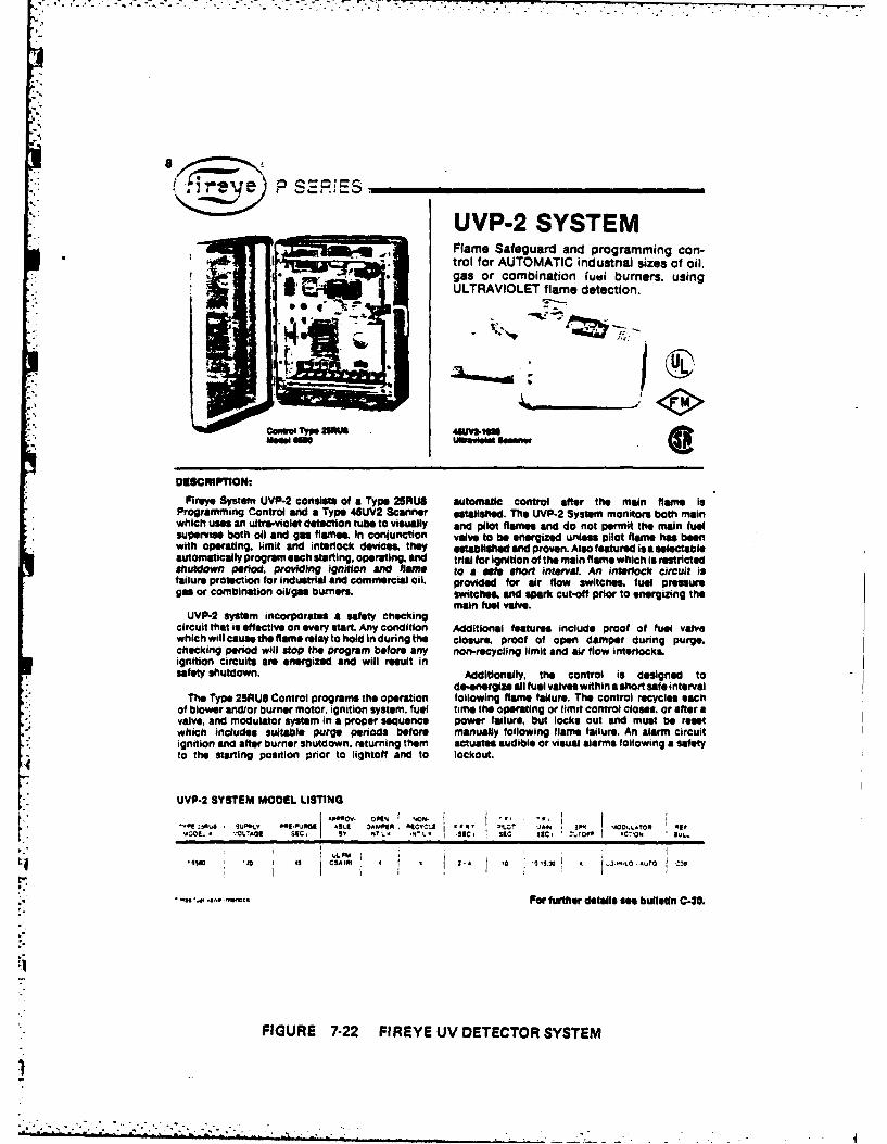
P SECiEs.
UVP-2 SYSTEMFlame Safeguard and programming con-
AI*.Itrol for AUTOMATIC industnial sizes of oil,gas or combination Wil burners, using
3 ~-j ~ULTRAVIOLET flame detection.
DESCNIPTlON:Fireye System UVP-2 consists of a Type 2SRUS automatic control after the main flame Is
Programming Control arid a Type 45UV2 Scanner eetallsewd. The UVP-2 System monitors both mainwhich uses an ultra-violet deteton tube to visually and pilot flames and do not permit the main fuelsupervise both oil and gas flames. In conjunction valve to be energized unless pilot flame has beenwith operating, limit and interlock dievices, they established and proven. Also featured is a selectableautomatically program each starting. operating, and trial for ignition of the main flame which is restrictedshutdown period, providing ignition anid Rem to a sete ~hr Interval. An interiock circuit isfailure protection for industrial and commercial oil, prvied for air flow switches, fuel pressuregas or combination oiligasi burners. switchs, and spark cut-off prior to energizing the
main fuel valve.UVP-2 system incorporates a safety checking
circuit that is effective on every start. Any condition Additional featurs include proof of fuel valvewhich will cause the flame relay to hold in during the closure, proof of open damper during purge,checking period will stop the program before any non-recycling limit and air flow Interlocks.ignition circuits are energized and will result insafety shutdown. Additionally, the control is designed to
de~nerglze all fuel valves within a short safe intervalThe Type 25RUS Control programs the operation following flame failure. The control recycles each
of blower andlor burner motor, ignition system, fuel time the operating or limit control closes& or after avalve. and modulator system in a proper sequence power failure. but locks out and must be resetwhich includes suitable purge periods before manually following flamne failure. An alarm circuitignition and after burner shutdown, returning them actuates audible or visual alarms following a safety
4to the starting position prior to lightoff and to lockout.
UVP-2 SYSTEM MODEL LISTING
-01! 75PU SUPPLY PolDUPOI AMB AMI 0 4qCVCt a -60 -ICP '.,A SP O,LAt04 -IFMOK- 'LAG sc , N N ISC MeC sec. ,Tof I AC V% SULL
CIPA J. C. O
I.I
,a.65 .a . Fnge or further details see bulletin C-30.
FIGURE 7-22 FIR EYE UV DETECTOR SYSTEM

7.4 Drive Mechanisms
7.4.1 Pneumatic Control Device
Function
The function of a pneumatic control drive is to position a damper
or lever operated valve in response to an input control signal.
Theory of Operation
Pneumatic control drives normally use an air operated piston to
provide the force necessary to drive the output lever. Compressed air
from an external air supply is required since the pneumatic input
signal is generally not used to drive the piston. A positioning
system is provided which regulates the air supply to the piston in
accordance with the input control signal. The positioner may be
either pneumatically or electronically operated, depending upon the
control system employed.
The drive piston may be either the spring-opposed type or
air-opposed type. With spring-opposed pistons, the air pressure
drives the piston in one direction, and a spring drives it back in the
opposite direction when the air pressure is reduced. With the
air-opposed type, compressed air is contained in both sides of the
piston, and the proper placement is achieved by increasing or
decreasing the air pressure on either side.
7-17

Hays- Republicmodel F410000 pneumatic final drive
*EASILY CALIBRATED *PRECISION POSITIONING * CAN BE FULLY CHARACTERIZED*H IGH STARTING TORQUE a EASILY MAINTAINED
N,.
description specificationsThe Hays-Republic Model F-10000 Final Drive CONSTRUCTION: Weahertightis designed to operate and position dampers,lover operated valves, fan inlet 'rates, turbin OPERATINGgovernors. and other control devices requiting EPRTRS 0 10Frotary torque precision positioning. MOUNTING: Floor, 4 %"s x 13"
bolt centers* This Pneumatic Actuator provides high starting
torques and rapidly positions th, final central CYLINDER: 4" x 5"element. Input signals are cam characterized OUTPUT: 00. goo rotation canmto accurately control the relationship of the caetr edri ve lever motion to a given input signalvariation. RESPONSE TIME: Less than 6 seconds
The Postionsr, is complete with all internal REPEATABILITY: ±.25%pneumatic piping required for the air supply INPUT: 3 - 15 psig or 15.- 3 psigand input signals.
AIR SUPPLY: 35.- 100 psig4The entire unit is weothertight, and suitable AIR CONSUMPTION- I SCFM
for temperature ranges of 00 to 1400F. All N *-9*[vrpstooperating parts ors, readily accessible for INDICATION O 90lerpstocalibration, servicing, and maintenance as CONNECTIONS: 1;8" NPT (Signal Input)
reqird.SUPPLY: 1.4" NPT
ELECTRICAL: 2 - 3/4" conduit knockouts
NET WEIGHT: 100 lbs.
FIGURE 7-23 HAYS-REPUBLIC PNEUMATIC CONTROL DRIVE

7.j
Bailey Control Systems Product Specification': P81-1
Pneumatic Control DrivesType AC
SBailey pnemuaic control drives Type AC provide remote-controlled power for positioning of regulating devices thinmechanical linkage.
APPLICATION
Bailey pneumatic control drives operate and positionregulating dem such as dampe, fan idet vanes. lever- operated valves. turbine governors and other devices requiring 7. - -an external means of power. Drives are actuated by electricor pneumaatic comg signals from automatic control or - #remote manual stations.
* Wide range of torque. Four sizes are available in torqueratlnp from 125 to 4000 ft4bs (169 to 5420 Nm).
* Suitable for hih temperte ewviommss. Units with AGA@ _pneumatic postioners can be used in ambient temperatures FIGURE I - p 4C0404 nene Cani Dn* fkft)up to 200 F (930C). Units with 1/P postionets operate witRaA Ens Type .4P chereeti paeftlener Typeat up to 180OF (82C). A C068 Premenri ConWl DOre (rut) i/Warmnn Type .4P
0 Characterizable postiong relays. Feedback cams can be
shaped to provide the relationship required betweeninput signal and fnal control element position. Controlsboth direct and reverse action of drive.
* Accepts electric or pneumatic control signal. See posd.-tioner Product Specification P88.7 (for CharacterizablePneumatic Positioner Type AP22) or P88-8 (for Charac-terizable I/P Positioner Type APS).
" Eam to istal. Can be placed in any convenient locationindoors or out and connected to the regulating device bystandard linkage components (see Product SpecificationG81- on control drive linkage).
. Quick che over to local hand operation from remotemanual or automatic operation can be made without lossof control.
A53AS6
FIGURE 2 - Both Type .4C0816 (lefti d Type .4C1016(fhrj heow internal Type .4P chectvifele pimsrione.
Bailey.ControlsForm, CV .K Litho in USA. 129090 igeo Ieat Ieoinwam 80CO.U
FIGURE 7-24 BAILEY PNEUMATIC CONTROL DRIVE

MODEL 7330PRODUCT DATA SHEET
COMPACT FINAL DRIVE
* HIGH OUTPUT TORQUE
* CHARACTERIZED MOTION
*ACCURATE ROTARY OUTPUT
*STANDARD MANUAL LOCX
WEVA THERPROOP ENCLOSURES
This versatile pneumatic drive unit is a low-costfinal drive for positioning valves, dampers, and otherfinal control elements. Compact sixe, a characterizingcam. and weatherproof can contribute to produce adrive Unit suitable for a great variety ot applications.And as an added benefit you can essily mount the rmning Cam segmn is unCUt. YOU can easily tailorunit in any position - indoors or out. Besie produc- your response by merely shaping the blank portion toing an excellent torque, the rotary motion .utput shaft your requidrements. Or just select the segment that willsimplifies installation. Linkage problems do nom exist. produce your desired results. Cam changing is comn-Simply mount lever in any position on the output pletely eliminated.shaft. Lever length adjusts to a full 13 inches.
The drive will opervA directly fronm a 40 to 150 palA characterizn cam produces various feed-becl air supply and does not require either regulation or
functions for given signal pressure changes. One por- filtering if attached to a clean, dry air source. Inputstionnof the cam produceaan output linear to the input. may be 3 to 13 or 3 to 27 psig. despending on whichwhile another portion produces an exponential motion you select. A manual operator and limit switches areapproxiately equal to the square of the input. The OptVAl accessories to provide even greater versatiity.
Madll.....................................................................'330
Input Signal ........................................................ 3toI L5 atoZt*7 psig
mazimum, Supply ?Ireasure....................................................... 1,0 psi
Minifma. SuPP1Y Pressure........................................................ 40 psi
Operating; Temperature Limits................................................ 0F to *200-F
14 ~ Sensitivity................ ........................................... 1/4,. orBte
Outpue Shaft Rotation....................................................... .5 Degrees
Time Required for Full Stroke:
Na Load....................................................................S8 Seconds
30 Pound Feet........................................................... 8 Seconds
50 Pound Feet........................................................... 9 Seconds
Wight.................................................................. 22 Pounds
FIGURE 7-25 HAYS-REPUBLIC COMPACT PNEUMATIC CONTROL DRIVE

- °
7.4.2 Electric Control Drive
Function
The function of an electric control drive is to position a damper
or lever operated valve in response to an input control signal.
*Theory of Operation
Most electric control drives use a reversible electric motor to
position the output drive lever. The motor acts through a series of
reduction gears to increase the output torque and provide precise
control. The motor does not operate continuously. It is started when
an input control signal is received and stopped when the output 0-ive
lever reaches the desired position.
Often a cam mechanism is included with the control drive which
can be used to "characterize" the output. Thus, the displacement of
the output drive lever can be made to vary with respect to the input
signal in accordance with almost any mathematical function.
7-18
. . . . . . .- - -

Hays-Republicmodels 873 and 874electric power units
application features
Electric Power Units are normally used incombustion and proeem control to operatethe final control element. These units have a insures immediate responu.
reversible motor and may be applied to opRer-ate dampers, valves, rheostats, variable speed REVERSILE MOTOR Rotation of out-
transmissions, fan couplings, stoker levers, put shaft is instantly reversible.and similar devices. Adjustable limit switches * RATINGS include high safety factor forare supplied to restrict angular travel of theunit. Additional switches can be installed tooperate signal lights or alarms, for transfer ofcontrol or for purpose of interlocking. Poten- NO OVER.TRAVEL: Friction baking at
tiometers for control application or for the rotor stops motor when curet is cut off.operation of remote position indicators are * PLUG-IN RELAYS with integral dualalso available. LI E L Strad
-. life feature.
operation * HIGH STARTING TORQUE always avail-
The Electric Power Unit is electrically con- able to overcome static friction.
nected to its controller. It is energized by re- 0 HAND WHEEL provided for manual oer-versing relays whose coils are operated by a AND
circuit closing device such as magnetically ation.
operated mercury switches, relay contacts oran electronic relay. A lever secured to theoutput shaft moves as the shaft turns. Link-age connects this lever to the final controlelement to be operated. By suitable adjust-ment of the linkage, either linear or non-linear motion of the final control elementmay be obtained.
FIGURE 7-26 HAYS-REPUBLIC ELECTRIC CONTROL DRIVE

IBailey Control Systems Product SpecificationI E81-4-2
Electric Control Drives (Modulating)Type RW
Provide remnotecontrolled power for precise positoningof regulating devices through meschatneca linkage.
APPLICATION
Operating and positiaong dampers. Iever-operated valves.and otlher regulating devices requiring an external mean ofpower.. Drives are actuated by electnicalignsls from an auto-matic control system or from a remote manual station.
FEATURES
* Modulating Con"eu. Speed of travel is propoutional to thevalue of the position snfot signal. As the signal approachesthe deied control point, speed decresses and virtually noovershooting occurs.
* Flexhie Control Clanestin Cam mechumn inproves control characteristics of regulating devicesi byproviding a simple adjustment for relation between Drive A7to?position and electric input sgAl.____ _________________
S Esy to hode. Control drrve can be placed in any con- FG E1-TmR5C neDsetah6,lfrflvenient location indoors or outdoors. Connected to Nmj) cane nerqe rat.the device being regulated by standard linkage (see Prod-uct Specification G81 -5).
0 Seam Ampilier is designed for indoor cabinet or rack * Dkmc Manual Operation. Quick changeover to directmounting, manual operation from automatic or remote manual
operation thru local interlock and hand crank.* Wide Range of Torquiss. Five sizes available in torque
ratings from 230 to 6000 lb-ft (3 1 to 8 136 Nm).Seric Accessibility. Easy access to drive components.
0 Equipmen Pwatiction. Motor current limiting prevents Plug-tn circuit cards allow testing and maintenanice whiledamage during automatic operation in the event that the drive continues operating under manual control.driven device jams. Torque Isit switches us providedto limit maimium output torque to a preset value. Torquelimit swiches use normally set to =20qb of maximum *Quick Disconnect Plug permits functional testing with-rated torque. Special factory sittings are available on out disturbing system wiring.request.
* Remote Stande Control. Precis joggng control bypasses * Wide Ambient Temperature Applications. -10 to + 160FServo Amplifier and can be accomplished with Ani- f-23 to 71C); low temperature lubricant available forfler Card unplugged to facilitate maintenance. operation at -30 to 4'160F (-34 to I1C).
Poe Ca-SI 111WInLIS. oo is &ioeiot ~Bailey~Controis
FIGURE 7-27 BAILEY ELECTRIC CONTROL DRIVE

K7.4.3 Pneumatic Valve Actuator
Function
The function of a pneumatic valve actuator is to vary the amount
a valve is opened in accordance with an input control signal from some
other control component.
Theory of Operation
Pneumatic actuators are normally the piston operated or diaphragm
operated type. The piston ooerated type perform in essentially the
same manner as any piston operated pneumatic control drive (see
Section 7.4.1). The main difference is that piston operated valve
actuators are specifically designed for valves and are mounted
directly on the valve yoke.
Diaphragm actuators are perhaps the most common valve positioning
device. They are relatively inexpensive and yet afford very precise
modulating control. They operate in somewhat the same manner as a
piston actuator, except a spring loaded (or air opposed) diaphragm is
used instead of a piston. The valve stem is directly coupled to the
diaphragm. When the air pressure is increased in the chamber above
the diaphragm it pushes the valve stem dawn, and when the pressure is
* decreased the stem comes up.
7-19

Numerous control options are available with pneumatic actuators.
The valve may be made to either open or close on loss of air supply or
even fail in place if desired. The valves may be operated directly
using control signal air, or the control signal may go to a positioner
which in turn regulates the actuator. If a positioner is provided,
the valve may be controlled using either a pneumatic or electric
control signal.
Pneumatic actuators may be used to provide either modulating or
on-off control. If modulating a control is required, valve
positioners are normally added since they greatly increase the control
precision. The positioner normally receives a feedback signal from
the valve (via a mechanical linkage) so that it is able to precisely
vary the valve opening in accordance with the input control signal.
7-20

al Babcock &Wilcox Product SpecificationP85-3
V-PUP *CONTROL VALVE
SPECIFICATIONS TABLE I
'kit PitoSSume Plus, Semn.O Sle m Taype 316 sam"WauCONNICIlON amee. Stelted ting seedfor ga.e our-
Gody: Serm-gi (ASTM AIX Clas SatCI: emboni steal lAffra A216 Gr. WC8W;
ACTU~tORor cierome-moly fASred A217 Gr. CU).
Voke: SUIII4Ui.Pecione: Sfluamaea Tu vfine~g for
P03M~ON fleow to 460 pm. tail vaas to LIOF:INOICATOR Cilwtteuil for stna oer 490 pe or
wintver m400P.Actueter Seems Sumn mames amee.
Dlpv~ : OWNe N NWts nylOn 11ne
-IWW Caw. 1111 Saee.
rMON V.C
PACKING* CR~e Normally Oler(anr-lo lelaacbti
TYPE VFA CLAS Stdus 26.:010. Sal. 00.w 2. ar 2.0
FIzUR .-- Noamael Duahxgm.cwae W4V" Pup ContCLAS CL111-S C:OE* 3 h 2
INCH ~ ~ ~ ~ ~ ~ .u IPTiuOuSRWE. reGI Smnw Table eg I f 3Po7 X or 3.15msan
The~~~25 TYPE 2W.A CLAS. OW. 90r or Iay S ( idout~~~~~le-seat.~~~An co n oto udd VPr tag hpO Smpig Seme le Pep 2.ta
IGUE Iosat eqal pcngin-caed, pCnrl" andrc tflwwl 5eevgl t era
resukm fromsir equalar chage inge oalf 3-27 oor al3-e15 f9n. n40de P" P~y fidicatren Mut-
AnedebW~ oop etedgerelay 'es in el e ee
po conl unio pecnclude chanacerstcs flo pro suetrol, steam Nt:d AreevS:Inle ,316o itcl s:m a pois ~ ~ ~ ~ ~ ~ ~ ~ !*lttt hoee Ponsdunt eqalpecntgecane nraeafflw il ww
resufrem reualg ec. sriceas in ne valve s litf rHo eig availabePe-.
stutl b ak. trCeeny16
AII # iiic;otomi al a
FIGURE~~rouc 7.28co BAILEY PNEUMATI VAVsATATRDIGAMTP
.P~ s o tos* bw. if. t-om w 111110"'- - - --

Babcock &Wilcox Product SpecificationP85-2
BAILEY PISTON-ACTUATED CONTROL VALVEThe TYPE V). CLASS DIOK. DIOF. er DLIG valve .io the helsate"
deelelseae. cagergiMed V-pert design whet.e penl amnie deteiminedby she sa ad shape of case pens. Iegal piate, amuletr ptevidesample poe..
APPLICATIONFor accurate. dependabl throullae ceetrol ith moniends noise and
snammavailability Inie editions of high initial pleasue, high=epea~e ad high pressure dealp. Typical applications inclue food
. at ,. asm pressure loedg s.r
PHYSICAL CHARACTEISTICS
Coge. Stem and Din: Typ 3stajales steel 4CLASS 010O) ; Type304 stalale deel wih sei e aing surfaces -CLASS D1V I; or
Ty~rDsw teel da ith doelieed owaing od saing seslaeaaBody: Carben stea I 15TM AZ1 Ge. VC~B: o etoemeoeey
ASYM A21t 7 e. WC6 se Ga. CS.Yoke: Senmet.Siem aed Boesch Block Parking: Suita"l fee specific valve speending
Indane, med sepavm.
Stem umwe ap to sleow.
TYPE VJI: Sheglerylle. I W diameter jad a' dtrakes with poeellmWleVslay Shleeln 0 diamete aad 11 earekot with peaition.
"PVJ3. Sholeg lladee -10 diamete add V" .tralat with peIle.4 ...1:Tweryislld f' diameter aod I" st*) with peeitle. .
ins relay.MG I et O khfdV~ C rWSeer Table 1. Pave L. fer accuts used vids varieus sia velvet. Velve, TMP VJ, CLASS 01011, 0101, er 0100.
Pregewe standards a" Ends(s06. 9". 1500. of 200 psi be having raised face Ntanged or woldlas rI-- -- -- -- -- - -- --- - - --- - ---- -
adsds dealgeed to ASA "tn=ads See Table 1. Page L. for coreospeadieg I QUOTATIONIORDERIIIG INFORMATIONsince Aed metevuals Ring jeint Aegoee me carbon steel welding ends on I
Standard sigal ranges of 3.13 or 3.27 ps. 10 prig suspply presure V400T CONiROI VALVII me fellovernrequired for pealionift rease. noPlw"a Cedits
shipping: See Table L. Page Z. I tnie eelyNet: Appervsmasli 85% of shipping feld. AMII5UU .
Aieumnem lawm Peee -peMAXIMUM RECOMMENDED VELOCM~ES Rawd T. Prhot -
Seam. Air, or Ga.:- 58.000 fpm outlet. I p9e dse YWater ,350 psid and JSOF t: Carben steel body - to fps. Seemi~tee I la-ve Drop at Muunt L Cepeesy _ psi
body - 20 fps: Ge. WC6 ehromeosooll body - 23 fpe: Ge. CS elsrme Plaes 0 eDeep a Autimme Cep estR.....------------.....psimely body -; lSed. Ie In s veeem at Monitmrem cap"ety...V..... -ow......e
Volve Inle he. .... edeACCESSORIES Val 1~ Sue.imu s..nie
Standard: vale.. otherwise spetlised. peice includes eharuoterseed CGRtil presieant C: 3.27 paes 3-15 *peviomsen resy sewe Producet t
poeeiratioo PW.S1 : air failure leit with propose Stemsslen r: 600 pit = 900 pelmaodl eset .integral reeling heed 'standard uuceed for 60 pelsi lv
'sis 3i ~ s o sae ize -ith optienal. seplarte casting cooling ied; i :10 eg 50pipeli. inlete:nd instruction bank.I " Nd M ge: Wdsg
Available: Position transmitter see# Product Speeiltaioe P99.10p: I Aeaesomefied minimum step air failure sam: travel limit switces; sto Llubricator and isolating valve. expanded outlets in seem sis. .-----------------radiegiaplsy. itender Met.' Ceepass,19114
PNEUMATIC EQUIPMENT
FIGURE 7-29 BAILEY PNEUMATIC VALVE ACTUATOR-PISTON TYPE
1.- .-- . - . --.--..-.-.- ~.---t .A

U Balil Babock Wicox Product SpecificationP88-6
PNEUMATIC PROPORTIONAL POSITIONERType API
The Type API Proportional Posmouner provides tast.sensitive and accurate positioning of double-actingptonicylinder assemblies; and usigeacttng spingl orcushion~loaded diaplsaum actuators in respons, to in inputsignal 13-I5 or 3-27 psagj from a pneumuatic controller devie.
The Pbsitioner is usually located in the c:ontrol loopbetween the c:ontroller and the final control element powerdevice (cylinder or diaphragm actuator). A mechanical contnec'tion to the final control element is used to teed back theactual position. When the controller calls for repositioning, thePositioner acts as a pneumatic relay. thru ats independent airsupply, and changes the piston or valve to the new requiredposition.
0 Stable positioning characteristics are provided for bothsmall and large cylinders or actuators.
0 Large gasiair capacity i greater than ZS scfm at 75 psi) forfast final control element response while mnaintaining lowins uiage.
0 Wide range of operation. Standard stroke ranges from0 '5" to :4.0'.
0 '4 psig maximumn input span. Includes standard inputsignasI of 3.15 psig or 3-:7 psig and affers a variety of FIGU RE I Type AP I Pneumatic Proportional Positionersplit range capabilities lie. 3-9 psmg, 9-15 psig. etc.).
* Good vibration resistant characteristics to final control0 LUable for double-acting or single-acting service. A valve element movement for accelerations up to Z 's and
idjustment procedure permits changeover from double- frequencies below 00Hz.ictings to single-acting operation.
* Positive mechanical feedback provides accurate tinal* Action (direct or reverse) is changeable in the field control element movement nor each value of input signnal
without the need tor any additional parts. applied.
%! Capable of operating at ambient temperatures up to :SOF 0 Most Positioners available as off-the-iself unitt.and supply pressures up to ISO psig.
0 Small compact size allows tor easy handling and instaila.0 Externailly adjustable span and zero for each stroke level. t.
FIGURE 7.30 BAILEY PNEUMATIC 'VALVE POSITIONER

. .. .. .. . .. . . .. . . . . . . .. .
7.4.4 Electric Valve Actuator
Function
The function of an electric valve actuator is to vary the amount
the valve is opened in accordance with an input control signal from
some other control component.
Theory of Operation
Electric actuators may be either the motor operated type or the
solenoid type. Motor operated actuators are in general rather
expensive and are normally not used on small industrial boilers. They
- .utilize a reversing electric motor acting through a series of
reduction gears to position the valve. The motor drives the valve to
the desired position and then stops. Torque switches and/or limit
switches are generally included for motor protection.
Solenoid actuators are much less expensive than motor operators,
but they are much more limited in their application. Solenoid
actuators can only provide on-off, or wide open-shut valve control.
Furthermore, they are only practical on small valves, generally less
than two inches in diameter, and are normally only used on valves
smaller than one inch.
Solenoid actuators use an electromagnetic coil to position the
valve plug. The valve stem is usually an integral part of a magnetic
plunger which passes through the middle of the coil. When the coil is
energized, electromagnetic force causes the plunger to move either up
7-21

or down, thus positioning the valve plug. The plunger is spring
I .loaded, so tnat when the coil is de-energized, the valve plug returns
to its original position. Solenoid valves may be designed to either
open when energized or close when energized, and either alternating
current (ac) or direct current (dc) may be used to energize the coil.
7-22

O fuel valves and actuatorsV403AA; VUU3S SOLENOID GAS VALVES
NORMALLY CLOSED perature: V403SA, V803SA-125 F [62 Ci; V40116-SOLENOID GA VALVES 140 F [60 C). Listed by Underwriters Lallwatories Inc:FOR MEDIUM PRUS- Industrial Risk Irwm Iflralya FIA) approvabl.SURE GAS BUIRNER&. Factry Mutual apaoved; Canadian Go AssociationMay be used as safet car tiad; American Gas Admociaton certified.dwiatff valve an pilot ormain fuel su@piy lnae. Suit-
Wfor 1, natural, ormauatured Bas. Valve
Pattern: StraightttrouhMaximum Ambient Tam- REPLACEMENT PARTS:
CWi Assemblet-
jdusgf 1 oy a s
Ii76401108 A 240 wsooss0
1mle. ( A 2emynl yan .22 m
ecopme of x saton at faloewlaie eewmasei CelONgeamsovew
-wglm AHMhIssWs CGLOiUSCIarnA 221 105
_______________________cams a 1 s 130
V4=2, VOM lSimumelee In ia. ev enue i oautpr elc
USGSX Hal 11111 . FAIT PILOT TAP
V 6 1 001 120 3/ 0 1 61. 108 3.1 1/8
V403SAI027 12 314 3.0 120.7 1 43** 13.7 V$V403BA1035 120 1 1.5 1 10.3 772 21.9 -1a
V40S I 1 -/ . .1 39.9V403SAIoi !U ______ 1. 1lE 58 U .___V4038AS076 240 112 T 1 34.5 228 1 ? 6.7 1
v'5=Aio2 -TU _____ 1.8 10.3 1. 1.251 I L 30.0 :
V40MAIlII -1/ 1.0 1_4_ _ 9. i
V4031103 1200 3.. 1. 11/V403MIC0420D 11 2 .2 6.0 5 3. 222 30.0
lmSUSO 1T 12W/ 1.0 1 F L9 (w 30. 114VEA1OO2 1 24 1.71/4 1.25 1 . 106 IO L 3110 114&Cf feet. ps1000 Stuiam ft. 0.64 on W. VA. I inaf, ve (m3lhr. 37.3 Mj/m3. 0.64- qigrI at 0.25 ktal.
TRA DEL INE_________
FIGURE 7-31 HONEYWELL SOLENOID VALVE
7.4.5 Hydraulic Valve Actuator
-: Function
The function of a hydraulic valve actuator is to vary the amount
a valve is opened in accordance with an input control signal from some
other control component.
Theory of Operation
Hydraulic valve actuators operate in basically the same manner as
pneumatic actuators, except that a liquid instead of a gas is used as
the motive, or control, fluid. Either a piston or diaphragm is
provided, and the hydraulic pressure acting against it is varied as
necessary to position the valve.
Hydraulic actuators may use liquid from the process piping
upstream of the valve as the motive fluid, or they may be provided
with self-contained hydraulic oil systems. Pilot valves, either
electric, hydraulic, or pneumatic, are used to regulate the flow to
and from the actuator diaphragm or piston.
7-23
. -___,______--. .-- - - - I- *-

fuel valves and actuators-V 055ABDE ON-OFF FLUID POWER GAS VALVE ACTUATORS-
USED WITH V5055_____VALVE TO CONTROL
GAS SUPPLY TO COM6
TRIAL BURNERS.
p..... ~ Refer to ordering tableII ~ for application. Rated for AUse.I
final safety shutoff service X. TCH
V5055 valve. Indicators onvalve and actator provide .- U
constant visual. indication of valv position.. Valv an 1 VALVIactuator can be mounted in any Position. Actuator CLo"Dmounts directly to valve bonnet with 2 seces sICN
Ambient Temperature Ratig: Minus 40 .to plus 150 FI mnus 4to plus 6C) for60 z models. CosingTime: 1 second maximum. Pressure rating and approvals;for these actuators depend on the valve usad. Refer to "c"U5C6 50Tc seCIunI O
VALVE-ACTUATOR APPROVALS and PRESSURE oRwXO ns~c1 uianse 001114411.
RATINGS, page 23L. US. IsvALL IA010116
V4055 Actuator mal covier vemaimdELECTRICAL RATINGS.V40SIA.D-
VOL.TAGE/I OPENING ISTANOANO) OPENING IF I1 HOLDINGPRIGIJINGY IRUSH IWATTS I hAS I VA F INRUSH ! WATTS I J LA A
20810HE 2.7 P 54 0. 1 5 TO555 40 72. 0 1 160 1 9.1 0.ji±...1.240V/00iMt 2.5 51.0 10.411 115 4.0 171.5 1j~ 0]6 1 10 92 10.5 1
VdO6IS.E -1 20V. 10Hmt. AUXILIARY SNITC14 ANDO VALVE-CILOSED IFAC-Opening-4O wets, 0.94 amp IA amp innids). TORY MUTUAL) SWITCH RATINGS: 1/2 hoe.
115 VA. LOAD I 126Vf I 24ovHolding-9.5 watts, 0.16S amp., 19 VA. Full Load 9.6 aims a's am
DAMPER CRANK ARM RATING (electically drives Lo io ovau S11. to 1ot- 29.4esI unad
damper in I direction only): is 100 VA.Stadar Molei- 2 0 lb maximum at 2.11/18 in.
radius at Plus 20 to Plus 150 F. and 5 lb at REPLACEMENT PARTS:minus 40 to plus 20 F [9 kg maximum at 6 mm 13358 Auxiliary Switch Bag Assembly.radius at minus 7 to plus 66 C. and 2.3 kg at 133569 FM Proof of ClosuretUL Valve Seal Overtravelminus 40 to minus 7 C1. Interlock Switch Bag Assembly. Must be used with
VUOSIC or E: do not use with VS034 valve body.Models with Damper Shaft Return Sortn 10 lb 7610GR Damper Crank Arm (damper arm and clip).
maximum at 2-11/16 in. radius at plus 20 to plus No other pan replaceable.150 F andl 5 lb at minus 40 to plus 20 F (4.5 kgmaximum at 08 mm radius at minus I to plus ACCESSORIES:66 C, and 2.3 kg at minus 40 to minus 7 C1. 133566 Auxiliary Switch Bag Assembly.
133509 FM Proof of ClosureiULI Valve Seal OvertvsvelInterlock Switch Bag Asselmbly. Must be used withV5C or E. do not use with V5034 valve body.
7616BR Damper Crank Arm (damper arm and clip).1 33533A Short Stem Adapter for mounting actuator
on V5034 valve with shofl stem.MAXIMUM DAMPER SHAFT ROTATION: 52 angular 133534A Long Stem Adapter for mounting actuator
-. . deges on V5034 valve with long stem.
*TRADELIE__________240
FIGURE 7-32 HONEYWELL HYDRAULIC VALVE ACTUATOR

-
Hays-Republicmodel F-04632
hydraulic position regulator* RUGGED CONSTRUCTION e WEATHERPROOF CASE * CHARACTERIZED OUTPUT.
POSITION INOICATING RELAY OPTION AVAILA3LE.
-.S
Realess Of the utaigen, et of the sm a ut o .The pOapplication ar" of Petl, me orvcle of valve balancing lever Is p at
The l'tsys-RePublic Hydrulic operation is thie sam for thi it left end to thescum folowPoiton Regator is used to re- tye of p er. lever. Since Ivot pointuW Me posetion of a hyrlic hed stationary a Vie beginningpiston operated side valve. Am r of the cycle, the aghtmad end ofloading pressure recelved ether the balancing lever is movedfrom a controlle or a manual or downward. This moves the PlotIi stationis used to cont: operation ,conecting link and su,th action of the reltor and The Pouitioner is an of opelted in a movement of the multi yinghenCe detemine the position of regulating device of the position- Vlvo Which prducs a move-me slide vev ing tpe. It t ioang ment of the pilot vave. The pilot
aTheattached curve, Figure I on pesure impulses - received valve is connected to a suly ofreverse aide, illuntes the reis from a controller of to flow con- ol under prese. When metionshlp betwesen mte p' Pressure trot. level control, hand control or veive is moved from its neutral orapplied to me loading diep'fgm other type of meeter control do- nim-post e presua r is in-
and the power Piaton position or vee. a converts ti ar pros- Cssed on one end of tme powervalve stroke. su No a definito position of a iston a decreee on the op-
power iton. In this paticulr posie end. This produces apowrguater isto. Inis p a movement of Me power piston.th e re g u la to rc ,,, , , o , , o , o, , ,slide valve. Its action is controlled
-.The H c P r consits manually or automatic..l, 'oni a piston will move from right to leftof a ca iron case upon which remote ,ontrol pane. and produce a counterclockwiseofe m on e pon c rotation of the circular cae pui-wemontly. a l oilot valhe a- ley which holds the can plate.sembly and return motion as- The cam roller is hold against the
somnivy edge of the cam by a spring. andS al ao ioperation cycle therefore,. folows Me shop ofSuch a rgU r 8 illustrated by the cam so0 th me caM leverFigure 2 on reverse side. There With zero prem on the load- turns on its supporting shaft tomay be ctab variations in the ing diaphragm the power Piston rese the pilot Valve to neutral. Aarrangement of the return motion is at the end of ft stroko. Ap*Ii- decam in pressure on the load-to accommodate vertical or no- cation of pressure on tho lad- ing diaphragm causs a reversalizontal Position of the Power re- ing diaphragm Canes it to move of all the movements doibedlay cylinder, downward against the resure above.
FIGURE 7-33 HAYS-REPUBLIC HYDRAULIC VALVE ACTUATOR
NI
, -, .... . ... . - ---. . . - . ._ - . .: :..: , : : - . . -. . .. ... .- - - . . . ,. - . _ . . . .
7.5 Recording eie
7.5.1 Circular and Strip Chart Recorder
Function
The function of a circular or strip chart recorder is to keep a
continuous record of one or more boiler operating parameters.
Theory of Operation
A circular chart recorder consists of a motor driven disk on
which a paper chart is located, and one or more pen mechanisms which
plot the desired output on the chart. The disk rotates very slowly,
usually once every twenty-four hours. The individual pen mechanisms
receive continuous input signals from various boiler parameter
measuring devices, such as pressure, temperature, and flow
transmitters. The mechanisms cause the individual marking pens to
move laterally on the chart (towards or away from the center of the
disk) in accordance with the magnitude of the control signal.
Circular chart recorders may be designed to receive either
electric or pneumatic control signals.
Strip chart recorders operpte on essentially the same principle
as circular chart recorders. The only difference is that the pens
mark on a rectangular "strip" chart which is rolled continuously from
* one reel onto another instead of a rotating disk. Since the strip
chart can be made very long if desired, the same chart paper can be
used for several days or even weeks.
7-24

Hays-Republicmodel 2100
12" circular chartrecorder
DESCRIPTIONThe Maya-Republic
Model 2100 is a voe-tWe Ir circulalrChart re-corder. The Model 2100 Re- The inik systemt design insurescordar can be custom built from ach pen a continuous ink flowstandard plug-in measuring Ole with a three to four month inkMonts to meet specific process re- supply in seoled Cartridges. STANDARDcording requirement$. The Model Chart replacement is simple and2100 Recorder is capable of ro- -May be accomplished with one SPECIFICATIONScording andlindicating from one to hand. Instead of keys, nuts.four promes measurements. Chains, or loose pairts, the Model Standard Chart Drive....
A quadrant or zone arrangement 2100 Recorder has a spring latch . 24 hour: 115 voltpermits an extremely wide variety that seats the Chant firmly on its 60 cycle A.C.of recording, indicating, and inte- drive to prevent slippage.grating combinations. The quad. Diseingaging the chart latch Hysteresis .... 0.5% or lessrant design allows simple install- automatically lifts the recordingation of up to four completely pens from the Chart. Resolution .... 0.2% or ISeaunitized plug-in measuring eie- The chart holder and automaticMents for process recording. A pen li fters are secured to the Chant Ambient Temp. Effect ..maximum of two flow Masure- plate. This plate simultaneously .. 0.4% per 50* F.Monts with continuous integration provides a smooth recording sur- Changeutilizing all four guadrants is an face while protecting the Chartavailable construction, drive mechanism. The chart beaw- Barometric Pressure Effect...
The Model 2100 Recorder has a ing bracket, Ca8e. and Chart plate .nonerugged caae which is easy to in- are internally constructed to in-stall and maintain. The ame is sure permanent alignment. Recorder Weightweather resistant and designed to Optional indicating scales and (No Receivers) .... Approx. AO lbs.prevenot entry of dust, moisture, fluorescent Chan lighting areand Other harmful ambient 411e- available for operator conven- Specifications subject to changeMonta. eonce. without notice.
FIGURE 7-34 HAYS-REPUBLIC CIRCULAR CHART RECORDER
o . . .
-. - . . :.

* ,. *. -
.-. .-
Hays-Republicmodel 2550
strip chart recorder*ACCURACY OF - 0.5% 0 SOLD STATE. PLUG-IN COMPONENTS*
* ONE. TWO OR THREE PENS * OPTIONAL ALARMS
.4,
"--+ DESCRIPT'ION ACCESSI, ORIES
The Hays-Republic Model 25M Strip Chart Recorder AltRm switches. to a maximum of two per pen. mayprovides recording of up to three vanrabm on a 4' be added as an option. The switches are can-oerated.
strip chart while providing a highly visible indication of SPOT-type and may be adusted to trip at any pointthe variable. Ribbon-type indicators are color Coded to within the span. Each Switch is rated 212 amps. at 125the pen color and provide indication at up to twice the to 250 VAC.distance of conventional pointer indicators. A retransmitting slidewire may be added to any pen.
The servo-operated. null-balance recorder uses a The potentiometer values are 1 to 1,000 ohms for gen-fully transistorized plug-in amplifier. Input circuits are eral purpose applications and 1 to 32 ohms for use with
electrically isolated from the power line AMd Conduit, the Hays-Rlpublic Model 2240 Integrator.and are isolated from each other in mulbpie en units The 2580 Recorder may also be provided with exter-to eliminate interaction betwoen signals. nal ON-OFF control of chart drive and servo-motors
The servos operate on a 0-1 volt DC signal, and may which makes it ideally suited for use with process chro-
be used on any of the common inout ranges by proper matograph to provide trend recording.selection of the input resistor (e.g. 1-5 mA DC. 4-20 mA ACCESSIIUTWDC. 10-50 mA OC. etc.). The recorder haa been designed for em of msinte-
The design of the servo is such that maximum power nance and calibration. Zero and soan adjustments areis available to overcome iherent friction or other accessible from the front, with no need to withdraw the
sources of inaccuracy. A system accuracy of =0.S0% is chis from the came. The chart drive mechanism flipsobtained with a samtvy of 0.25%. As a result of the out at the touch of a lever to allow chart changing with
power afforded by the savo operation, it , possible to no need of removing the drive mechanism or chassisadd accessones directly to the WV drive. from the case.
F
• "" FIGURE 7-36 HAYS-REPUBLIC STRIP CHART RECORDER

Bail y acciWlo Product Specification1
BAILEY 7000 RECORDERSType 771,772 and 773 NRROW ROLL RECORCER
Records up to three procilss measurements on a 4-inchrectilinear chart. Color matched indicators track with the '
recording pens. providing accurate, highly visible indications.Pen motin is servo driven by a plug-in high gain null .0-
balance DC amplifier, providing fast, accurate response. Therecorder chassts mounts in a standard 762 panel or rack 9mounted shelf and connections are made through a plug and-
cable asumbly. rcrigu o1 aibea ela
Type /71. 772 and 773 Recorders are fully competible so-with other Bailey 7000 instruments, including the Type 770
for genral usein recording DC signals from many other 7poesinstruments. -e
Input Sigal ChokcetoS5. 0to 1,0to S.0to1. -10 to+10v DC or4 to en2mDCpowered from recorder or self-powered.ImrvdOperator Convenience &Wi UnWe.rstning -46
The hr displays:Tye71Narrow Roll Chart: High recording density, up 30
to3pes in inch-wide recorder. Up to uighit hourinsantrevew.Twohours visible on the face of recorder.
six ore ourswith recorder partially removed from 2
Tye72WieRl Chart: Up to 13 hour instant review.Six hours visible on the face of the 3.6 incls-wide recorder.seven more hours with recorder partially removed from - ..enclosure.Type 773 V~old Chart: Up to three hours visible on theface of the recorder. The entire past record may be viewed-by opening front window jad pulling foldied 'hart paperREPEfrom take-up chamber. This is also a 3.6 inch-wide BU Erecorder. PE
0 Chart transport nssmbly completely removable forhistoric review and chart change without operatorinconvenience.
* Operator supervision maintained during chart removal byinderpendent bar graph indicators that communicateprocess meauremnent to operator.
0 Unique two-way door for operator notation andMaintenance convenience.
0 Highly visible color coded bar graph indicators to inatchpens.
Mininwim Maintenfle with Simpl ified Serviciung FULL SIZE0 Quick change. disposable one piece pen and ink cartridge.
Easy one step replacement. Ink .;artrdge life. up to ninety*Jays of normal usage -3000 Ats914.4m)o)ftrace. FIGURE I -*Type "71 Narrow Roll Strip'Cliart Recorder
FIGURE 7-36 BAILEY STRIP CHART RECORDER

-APPENDIX A
SIGNAL PROCESSING FUNCTIONS-.CFunction & GraphicSymbol M Reprusntation "
. ST heoutput equals the algebraic sum ofthe inputs.
AVERAGING is + 2 +. + as ,, The output equals the algebraic sum ofM, the inputs divided by the number of
inputs.
DIFFERENCE I1Th output equals the algebraic differ-A2 ence between the two inputs.
PROPORTIONALa KRX The output is directly proportional toj the input.
N ~ The output varies in accordance withINTEGRAL both magnitude and duration of the in.
* I"dt put. The output is proportional to thetime integral of the input.
It
DERIVATIVE d 1....... The output is proportional to the rated/dt of change (derivative) of the input.
MULTIPLYING The output equals the product of thex ~two inputs.
DIVIDING 2 The output equals the qoduct of the
22 *I-. X ..n . Lu..., two inputs.tOOT
EltCIN ,- The output equals the root (i.e., square
- zz z i inputs.,
EXTACON M - --- root. fourth root. 3/2 root. etc.) of the.... input.
EXPONENTIAL The output equals the input raised ton " m-a power (i.e.. second, third, fourth, etc.)
A-1
*IN ACCORDANCE WITH THE SCIENTIFIC APPARATUS MAKERS ASSOCIATION (SAMA)
.",.!..-.-:,-:.':.,:.-:-i- .: .:.5..-.. :::":- .:,- 5 -: :,.--------,-.-,.--...-,-------------,---: "

-7--'
SIGNAL PROCESSING FUNCTIONS (CONT.)
SybFunction & GraphicMath Equation Definition
Symbol Reprsentation
NUNSPECIFIE 02 The output equals some nonlinear func-FUNCTION m - ftion of the input.
TIME FUNCTION m - = fQ The output equals the input times someI f(t) M-flRDu function of time or equals some func-
tion of time alone.
HIGH SELECTINg M x, FORz, > ., x, The output is equal to that input which> . FOR xi <2.. is the greartest of the inputs.
" - I t I, I
LOW SELECTINO Gz FOil1 > 1 The output is equal to that input which<m - , FORN <x z=xis the least of the inputs.
HIG IUMTINS x zFORxN 1HFORX>N limit value whichever is lower.-FOR < L The output equals the input or the high
:.F _ limit value whichever is higher.
t, t ,
REVERSE I .PROPORTIONAL mw- Kx The output is reversely proportional to
-K the input.
d nd. The output equals the input as tont as
dtWIT dttere of change of the input does notLIMITING M TO exceed a limit value. The output will-chan.e at the rate established by this
PO TIR - ut the output again equals the
--K M-,t t t h input.
•AmS. ,The output equals the input pus (or
-ITor t 1rninus) some arbitrary value (bias).
A-2
......... ........ .t anl~p a h rt sabihd yi

K-
SIGNAL PROCESSING FUNCTIONS (CONT.)
-PunctionI & Math Equation Graphic DefinitionSymbol Reprusentation
ANALOG SIGNALIGENERATOR m , A OES NOT APty A The output is an analog signal devel-
A oped within the generator.
* TRASFERThe output equals the input which hasM :, FOR STATE I been selected by transfer. The state of
T x, FOR STATE 2 ,the transfer is established by external*- _______ _ STATE STATE t means.
STATE I < H4"SIGNAL , STAT STATES
MONITOR STATE 2
HI(E141AGIZ lt >H/ A'- '- STATE
to t to I
STATE.(ENERGIZED 04 SAT2 TT
STATE 2 ,,> L 1 1
STATE! mI The output has discrete states which are
,EST OUTPUTm, H <. - dependent on the value of the input.H/IL .ALRM STATt, WSTTE5T "hen the input exceeds (or becomesSTATE I less than) an arbitrary limit value the
( OTU of H , output chances state.ENERIGIZED ON z> H
ALARM STATE.
STATE IFRST OUTPUT 9: < L
ENIERGIZED onALARM STATE) o .
STATE 2
H//L INoUTIV S an L< <SH L 2 TATo f I .I It A G IZ E D ! -- -
if is t it t
STATE 3tSjCONO OUTPUT m
ENEGcIZIo On x > HALARM STATE)
The ariuble used in the tabi ar:: L - An arbitrary analog lo l alue
A - An arbitrary analog signal m - Analog output variabler b - Analog bias value n - Number of anaiog inputs or vaiue of exponent
7t - Derivative with respect to time t - Timc"d Tr - Dcrivatihe timeH - An arbitrnr' analog high limit value
x - Analog input variable- Integrating ratc .. . . x -- , Analor input % uriable I to n in numh,:r)
A-3

FIGR -0BILMATCVLED