boiler regulator ecomax 800, model r1 - ekokotle.sk executive module installation ... 13.6...
TRANSCRIPT

Boiler regulator
ecoMAX 800, model R1 version: ec FOR SOLID FUEL-FIRED BOILERS WITH FEEDING SCREW
SERVICE AND ASSEMBLY MANUAL
ISSUE: 1.2
APPLICABLE TO
SOFTWARE:
MODULE PANEL
v06.11.030 v06.10.014
v06.11.031 v06.10.015
v06.11.035 v06.10.016
v06.11.036 v06.10.017
v06.11.037
2010-04-09
Dzia Zintegrowanego Systemu Zarz dzania


TABLE OF CONTENTS
1 RECOMMENDATIONS REGARDING SAFETY ....... 5
2 GENERAL INFORMATION ................................... 6
3 INFORMATION ABOUT DOCUMENTATION ....... 6
4 STORAGE OF DOCUMENTATION ....................... 6
5 APPLIED SYMBOLS ............................................. 6
6 DIRECTIVE WEEE 2002/96/EG ........................... 6
REGULATOR INSTRUCTION MANUAL ..................... 7
7 STRUCTURE – MAIN MENU ............................... 8
8 OPERATING THE REGULATOR ............................ 9
8.1 DESCRIPTION OF BUTTONS ..................................... 9
8.2 DESCRIPTION OF DISPLAY MAIN WINDOW ................. 9
8.3 START-UP OF THE REGULATOR ................................ 9
8.4 PRESETTING BOILER TEMPERATURE .......................... 9
8.5 STOP .............................................................. 10
8.6 FIRING UP ...................................................... 10
8.7 OPERATION – MANUAL SETTINGS ....................... 11
8.8 OPERATION – FUZZY LOGIC SETTINGS ................. 12
8.9 CONTROL ...................................................... 12
8.10 FUEL SELECTION ................................................. 14
8.11 SETTINGS FOR DOMESTIC HOT WATER (DHW) ......... 14
8.12 PRESETTING DOMESTIC HOT WATER TEMPERATURE ... 14
8.13 ENABLING THE SUMMER FUNCTION .................... 14
8.14 DHW TANK DISINFECTION ................................... 14
8.15 MIXER SETTINGS ................................................ 15
8.16 WEATHER CONTROL ........................................... 15
8.17 DESCRIPTION OF SETTING NIGHT-TIME DECREASES .... 15
8.18 INFORMATION ................................................... 16
8.19 DISABLING FEEDER ............................................. 16
8.20 MANUAL CONTROL ............................................ 17
8.21 RESTORING USER SETTINGS .................................. 17
REGULATOR INSTALLATION AND SERVICE SETTINGS
MANUAL ............................................................... 19
9 STRUCTURE - SERVICE MENU .......................... 20
10 HYDRAULIC DIAGRAMS ................................... 22
11 TECHNICAL DATA ............................................. 25
12 CONDITIONS OF STORAGE AND TRANSPORT .. 25
13 REGULATOR INSTALLATION ............................. 25
13.1 ENVIRONMENTAL CONDITIONS .............................. 25
13.2 INSTALLATION REQUIREMENTS .............................. 25
13.3 INSTALLATION OF CONTROL PANEL ......................... 25
13.4 EXECUTIVE MODULE INSTALLATION ........................ 26
13.5 IP PROTECTION RATE ........................................... 27
13.6 CONNECTING ELECTRICAL SYSTEM .......................... 27
13.7 PROTECTIVE CONNECTIONS................................... 28
13.8 CONNECTING TEMPERATURE SENSORS .................... 29
13.9 CONNECTING WEATHER SENSOR ............................ 29
13.10 CHECKING TEMPERATURE SENSORS .................... 29
13.11 CONNECTING ROOM THERMOSTAT ..................... 30
13.12 CONNECTING RESERVE BOILER ........................... 30
13.13 CONNECTION OF ALARM SIGNALLING .................. 32
13.14 CONNECTING MIXER ........................................ 33
13.15 CONNECTING TEMPERATURE LIMITER ................. 34
13.16 CONNECTING ADDITIONAL PANEL ....................... 34
14 BOILER SERVICE SETTINGS ............................... 35
14.1 INSTALLATION TYPE ............................................. 35
14.2 ROOM THERMOSTAT OF THE BOILER ....................... 35
14.3 BOILER WEATHER CONTROL .................................. 35
14.4 HEATING CURVE ................................................. 35
14.5 BOILER HYSTERESIS ............................................. 35
14.6 MINIMUM PRESET BOILER TEMPERATURE ................ 35
14.7 MAXIMUM PRESET BOILER TEMPERATURE ............... 35
14.8 MINIMUM FAN POWER ........................................ 36
14.9 FUEL SHORTAGE DETECTION TIME .......................... 36
14.10 FEED TIME CONTROL .................................... 36
14.11 EXTENDING AIRFLOW OPERATION ...................... 36
14.12 MAXIMUM FEEDER TEMPERATURE ..................... 36
14.13 MIN. RETURN TEMPERATURE ............................ 36
14.14 RETURN TEMPERATURE HYSTERESIS .................... 36
14.15 RETURN PROTECTION ...................................... 36
14.16 RESERVE BOILER ............................................. 36
14.17 ALARMS – SIGNALLING SETUP ........................... 37
14.18 BOILER COOLING TEMPERATURE ........................ 37
15 CH AND DHW SERVICE SETTINGS ..................... 37
15.1 CH START TEMPERATURE ..................................... 37
15.2 CH PUMP STANDSTILL TIME .................................. 37
15.3 CH PUMP STANDSTILL WITH DHW PRIORITY ............ 37
15.4 MAXIMUM DHW TEMPERATURE .......................... 37
15.5 DHW TANK HYSTERESIS ....................................... 37
15.6 INCREASE IN BOILER TEMPERATURE AN ACCOUNT OF
DHW AND MIXER .......................................................... 38
15.7 EXTENDING DHW PUMP ..................................... 38
16 MIXER SERVICE SETTINGS ................................ 38
16.1 MIXER OPERATION ........................................ 38
16.2 MAX. PRESET MIXER TEMPERATURE ....................... 38
16.3 MIN. PRESET MIXER TEMPERATURE ....................... 38
16.4 RANGE OF PROPORTIONALITY ................................ 38

4
16.5 INTEGRATION TIME CONSTANT .............................. 39
16.6 VALVE OPENING TIME ......................................... 39
16.7 INCREASE IN BOILER TEMPERATURE ON ACCOUNT OF
MIXER 39
17 RESTORING SERVICE SETTINGS ....................... 39
18 DESCRIPTION OF ALARMS ............................... 40
18.1 NO FUEL .......................................................... 40
18.2 EXCEEDING MAX. BOILER TEMPERATURE ................. 40
18.3 EXCEEDING MAX. FEEDER TEMPERATURE ................ 40
18.4 DAMAGE TO BOILER TEMP. SENSOR ....................... 41
18.5 FEEDER TEMPERATURE SENSOR DAMAGE ................ 41
18.6 NO COMMUNICATION ......................................... 41
19 EXTRA FUNCTIONS .......................................... 43
19.1 POWER SUPPLY DECAY ........................................ 43
19.2 PROTECTION AGAINST FREEZING ........................... 43
19.3 PREVENTIVE COOLING ......................................... 43
19.4 FUNCTION OF PROTECTING PUMPS AGAINST
STAGNATION ................................................................. 43
20 REPLACEMENT OF PARTS AND SUBASSEMBLIES
43
20.1 REPLACING MAINS FUSE ...................................... 43
20.2 CONTROL PANEL REPLACEMENT ............................ 43
20.3 EXECUTIVE MODULE REPLACEMENT ....................... 44
21 DESCRIPTION OF POSSIBLE FAULTS ................. 45
22 REGULATOR SETUP BY BOILER
MANUFACTURER. ................................................. 47

5
1 RECOMMENDATIONS REGARDING
SAFETY
Requirements concerning safety
are described in detail in
individual chapters of this
manual. Apart from them, the
following requirements should
in particular be observed:
Þ Before starting assembly, repairs or maintenance, as well
as during any connection
works, please make sure that the mains power supply is
disconnected and that terminals and electric wires are devoid of
voltage.
Þ After the regulator is turned off using the keyboard, dangerous
voltage can occur on the
terminals.
Þ The regulator cannot be used at variance with its purpose.
Þ Additional automatics which protect the boiler, central heating (CH) system, and
domestic hot water system against results of malfunction of
the regulator, or of errors in its
software, should be applied.
Þ Choose the value of the programmed parameters
accordingly to the given type of boiler and fuel, taking into
consideration all the operational conditions of the system.
Incorrect selection of the
parameters can cause malfunction of the boiler (e.g.
overheating of the boiler, the flame going back to the fuel
feeder, etc.),
Þ The regulator is intended for boiler manufacturers. Before
applying the regulator, a boiler manufacturer should check if
the regulator’s mating with the given boiler type is proper, and whether it can cause danger.
Þ The regulator is not an intrinsically safe device, which
means that in the case of malfunction it can be the source
of a spark or high temperature, which in the presence of
flammable dusts or liquids can cause fire or explosion. Thus,
the regulator should be separated from flammable
dusts and gases, e.g. by means of an appropriate body.
Þ The regulator must be installed by a boiler manufacturer in
accordance with the applicable safety standards.
Þ The programmed parameters should only be altered by a person familiarized with this
manual.
Þ The device should only be used in heating systems in accordance with the applicable
regulations.
Þ The electric system in which the regulator operates must be
protected by means of a fuse, selected appropriately to the
applied loads.
Þ The regulator cannot be used if its casing is damaged.
Þ In no circumstances can the design of the regulator be
modified.
Þ Electronic isolation of the connected devices is applied in
this regulator (action type Y2
acc. to PN-EN 60730-1).
Þ The regulator consists of two subassemblies. In the case of
replacing one subassembly, make sure to maintain
compatibility with the other one. More information on that
issue can be found in the documentation intended for
fitters.
Þ Keep the regulator out of reach of children.
6
2 General information
The ecoMAX 800 boiler regulator, model R1,
version ec, is a modern electronic device the
purpose of which is to control operation of a
coal-fired boiler with a feeding screw. The
regulator is a multipurpose device:
- it automatically maintains a preset boiler
temperature by controlling the fuel
combustion process,
- it controls timing of feeding screw and
fan,
- it automatically stabilizes a preset
temperature of the domestic hot water
tank,
- it automatically maintains a preset
temperature of one heating mixer cycle,
and after equipping the regulator with
an extension module, it controls
(altogether) operation of three heating
mixer cycles,
The preset temperature of heating cycles and
boiler can be set on the basis of a weather
sensor readouts.
The regulator features an individual fuzzy
logic function. It allows to optimize the
combustion process, which is in favour of
natural preservation, decreases fuel
consumption and relieves the user of the
necessity of adjusting the burner
parameters.
Possibility of cooperation with room
thermostats, separate for each heating
cycles, facilitates maintaining comfortable
temperature in the heated rooms. Moreover,
if need arises, the device enables a reserve
boiler (gas- or oil-fired).
The device has modular construction,
consisting of a control panel, the main
executive module, and, optionally, a control
module for two additional mixer cycles.
The device is operated in an easy and
intuitive way.
Regulator can cooperate with an additional
control panel situated in living quarters. It
can be used in a household and similar
facilities, as well as in light industrialized
facilities.
3 Information about documentation
The regulator manual is a supplement for the
boiler manual. In particular, except for this
manual, the boiler manual should also be
observed. The regulator manual is divided
into two parts: for user and fitter. Yet, both
parts contain important information,
significant for safety issues, hence the user
should read both parts of the manual.
We are not responsible for any damages
caused by failure to observe these
instructions.
4 Storage of documentation
This assembly and operation manual, as well
as any other applicable documentation,
should be stored diligently, so that it was
available at any time. In the case of removal
or sale of the device, the attached
documentation should be handed over to the
new user / owner.
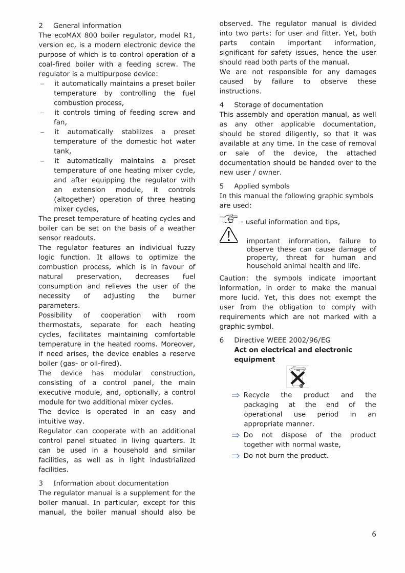
5 Applied symbols
In this manual the following graphic symbols
are used:
- useful information and tips,
important information, failure to
observe these can cause damage of property, threat for human and
household animal health and life.
Caution: the symbols indicate important
information, in order to make the manual
more lucid. Yet, this does not exempt the
user from the obligation to comply with
requirements which are not marked with a
graphic symbol.
6 Directive WEEE 2002/96/EG
Act on electrical and electronic
equipment
Þ Recycle the product and the
packaging at the end of the
operational use period in an
appropriate manner.
Þ Do not dispose of the product
together with normal waste,
Þ Do not burn the product.

REGULATOR INSTRUCTION MANUAL
ecoMAX 800, model R1

8
7 Structure – main menu
Main Menu
Info
Preset CH temp.
Adjustment mode
Standard
Fuzzy Logic
Fuel type
Feed time OPERAT
Feed interval OPERAT
Feed interval CONTR
Night time temp red.
Boiler
Mixer 1
Mixer 2
Mixer 3
DHW container Preset DHW temp.
DHW pump mode
DHW cont. hysteresis
DHW disinfection
Mixer 1 settings
Mixer 2 settings
Mixer 3 settings
Clock
Screen brightness
Language
Feeder
Manual
Restore default val.
Service settings
Feeder
Fan
CH pump
DHW pump
Contact 30-31
Pump Mixer 1
Mixer 1 Open
Mixer 1 Close
Mixer 3 Pump
Mixer 3 Open
Mixer 3 Close
OFF
Preset mixer temp.
Mixer room therm.
Mixer out. temp. dep.
Mixer heating curve
Polski
Cestina
English
Roman
Priority
No priority
Summer
Fan power

9
8 Operating the regulator
This section briefly describes how the
regulator should be operated. In order to
start using a boiler with the regulator, you
must fire the boiler up using the regulator
mode LIGHT, and then switch the regulator
into the mode OPERATION.
8.1 Description of buttons
Drawing 1 View of control panel
Legend:
1. MENU button
2. „TOUCH and PLAY” knob
3. EXIT button
Turning the “TOUCH and PLAY" knob increases or decreased the edited parameter.
This is an element of quick operation of the
regulator. Pushing this knob allows to enter
the given parameter, or to confirm the
selected value.
8.2 Description of display main window
Drawing 2 display main window
Legend:
1. regulator operation modes: STOP, LIGHT,
OPERATION, CONTROL,
2. preset boiler temperature,
3. measured boiler temperature,
4. field of values which influence the preset
boiler temperature: ,,T” – symbol of
decrease in the preset boiler temperature
due to disconnection of the room
thermostat contacts; „I” symbol of
decrease in the preset boiler temperature
due to active intervals; „W” – symbol of
increase in the preset boiler temperature
for the time of filling the domestic hot
water (DHW) tank; "M" - symbol of
increasing the preset boiler temperature
due to mixer cycle; "O" - weather control
for the boiler cycle enabled.
5. airflow operation symbol
6. fuel feeder operation symbol,
7. central heating pump operation symbol,
8. domestic hot water pump operation
symbol,
9. measured temperature of domestic hot
water tank,
10. preset temperature of domestic hot water
tank,
11. clock and day of the week
12. symbol of mixer extension module
MX.01, which allows support of two
additional heating cycles
13. outside (weather) temperature,
14. active fuzzy logic control symbol.
The domestic hot water window in the main
screen can be changed into a selected mixer
cycle using the TOUCH and PLAY knob.
Drawing 3 auxiliary window, note: the windows for
mixers 2 and 3 appear only if the additional mixer
module MX.01 is equipped.
8.3 Start-up of the regulator
The regulator is switched on by pressing the
“TOUCH and PLAY” knob. First, an
information window with the software
versions appears, then the regulator switches
to the STOP operation mode.
8.4 Presetting boiler temperature
3
2
1
1
2
3
5
6
10
9
12
4
8
2
7
11 13 14
10
Specify the preset boiler temperature by
entering:
MENU -> Preset CH temp.
and setting this parameter at the desired
value.
The preset boiler temperature can be also set
at the main window. Press the “TOUCH and
PLAY” knob in the main window and turn it to
specify the preset boiler temperature – the
temperature “pulsates”. Confirm the settings
by pressing the “TOUCH and PLAY” knob once more. In order to exit the temperature
editing, press the EXIT button.
The regulator skips the preset CH temp.
parameter when the preset boiler
temperature is determined in relation to the
weather. The preset boiler temperature is
temporarily increased in order to fill the
domestic hot water tank, and the mixer
cycles.
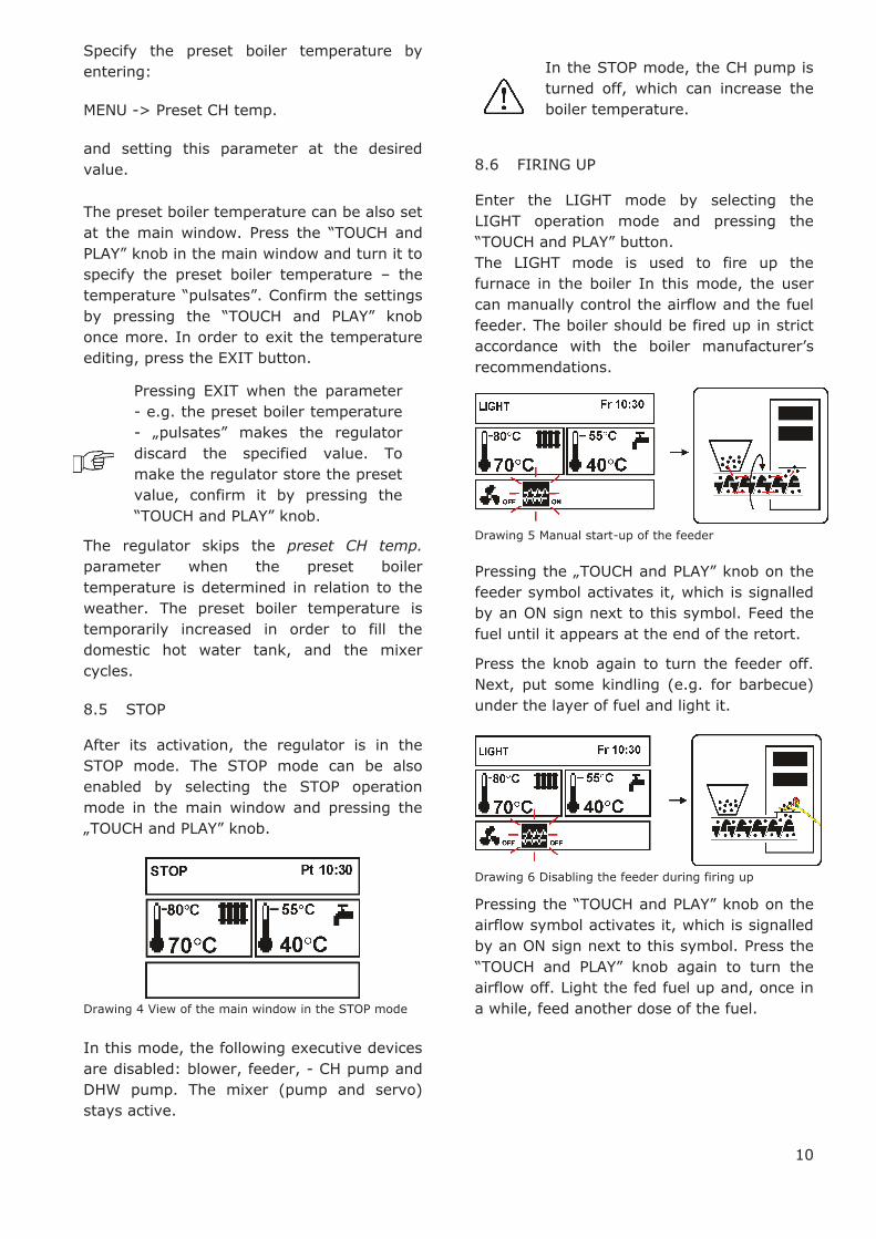
8.5 STOP
After its activation, the regulator is in the
STOP mode. The STOP mode can be also
enabled by selecting the STOP operation
mode in the main window and pressing the
„TOUCH and PLAY” knob.
Drawing 4 View of the main window in the STOP mode
In this mode, the following executive devices
are disabled: blower, feeder, - CH pump and
DHW pump. The mixer (pump and servo)
stays active.
In the STOP mode, the CH pump is
turned off, which can increase the
boiler temperature.
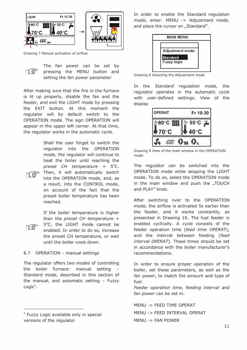
8.6 FIRING UP
Enter the LIGHT mode by selecting the
LIGHT operation mode and pressing the
“TOUCH and PLAY” button. The LIGHT mode is used to fire up the
furnace in the boiler In this mode, the user
can manually control the airflow and the fuel
feeder. The boiler should be fired up in strict
accordance with the boiler manufacturer’s recommendations.
Drawing 5 Manual start-up of the feeder
Pressing the „TOUCH and PLAY” knob on the feeder symbol activates it, which is signalled
by an ON sign next to this symbol. Feed the
fuel until it appears at the end of the retort.
Press the knob again to turn the feeder off.
Next, put some kindling (e.g. for barbecue)
under the layer of fuel and light it.
Drawing 6 Disabling the feeder during firing up
Pressing the “TOUCH and PLAY” knob on the
airflow symbol activates it, which is signalled
by an ON sign next to this symbol. Press the
“TOUCH and PLAY” knob again to turn the airflow off. Light the fed fuel up and, once in
a while, feed another dose of the fuel.
Pressing EXIT when the parameter
- e.g. the preset boiler temperature
- „pulsates” makes the regulator discard the specified value. To
make the regulator store the preset
value, confirm it by pressing the
“TOUCH and PLAY” knob.
11
Drawing 7 Manual activation of airflow
The fan power can be set by
pressing the MENU button and
setting the fan power parameter
After making sure that the fire in the furnace
is lit up properly, disable the fan and the
feeder, and exit the LIGHT mode by pressing
the EXIT button. At this moment the
regulator will by default switch to the
OPERATION mode. The sign OPERATION will
appear in the upper left corner. At that time,
the regulator works in the automatic cycle.
Shall the user forget to switch the
regulator into the OPERATION
mode, the regulator will continue to
heat the boiler until reaching the
preset CH temperature + 5oC.
Then, it will automatically switch
into the OPERATION mode, and, as
a result, into the CONTROL mode,
on account of the fact that the
preset boiler temperature has been
reached.
If the boiler temperature is higher
than the preset CH temperature +
5oC, the LIGHT mode cannot be
enabled. In order to do so, increase
the preset CH temperature, or wait
until the boiler cools down.
8.7 OPERATION – manual settings
The regulator offers two modes of controlling
the boiler furnace: manual setting –
Standard mode, described in this section of
the manual, and automatic setting – Fuzzy
Logic1.
1 Fuzzy Logic available only in special
versions of the regulator
In order to enable the Standard regulation
mode, enter: MENU -> Adjustment mode,
and place the cursor on „Standard”.
Drawing 8 Selecting the Adjustment mode
In the Standard regulation mode, the
regulator operates in the automatic cycle
with user-defined settings. View of the
display
Drawing 9 View of the main window in the OPERATION
mode
The regulator can be switched into the
OPERATION mode while skipping the LIGHT
mode. To do so, select the OPERATION mode
in the main window and push the „TOUCH
and PLAY” knob.
After switching over to the OPERATION
mode, the airflow is activated 5s earlier than
the feeder, and it works constantly, as
presented in Drawing 10. The fuel feeder is
enabled cyclically. A cycle consists of the
feeder operation time (feed time OPERAT),
and the interval between feeding (feed
interval OPERAT). These times should be set
in accordance with the boiler manufacturer’s recommendations.
In order to ensure proper operation of the
boiler, set these parameters, as well as the
fan power, to match the amount and type of
fuel.
Feeder operation time, feeding interval and
fan power can be set in:
MENU -> FEED TIME OPERAT
MENU -> FEED INTERVAL OPERAT
MENU -> FAN POWER

12
Drawing 10 Airflow and feeder operation cycles in the
OPERATION mode.
THE MANUFACTURER’S SETTINGS DO
NOT ALWAYS MATCH THE GIVEN
BOILER TYPE, THUS THEY MUST BE
ADJUSTED TO THE GIVEN TYPE OF
BOILER AND FUEL
The feeding time and feeding
interval should be selected in
such a way that the fuel would
not recede to the fuel feeder.
If in this mode the room thermostat
disconnects its contacts, thus signalling that
the preset temperature has been reached in
the room, then the regulator:
· lowers the preset CH temperature by
the parameter Lower preset CH temp.
to thermostat
(MENU ® SERVICE SETTINGS ®
PASSWORD ® BOILER SETTINGS ®
ROOM THERMOSTAT), thus switching
into the CONTROL mode,
· disables the CH pump by the time CH
pump start temp. with thermostat on
(MENU -> SERVICE SETTINGS ->
PASSWORD -> CH/DHW SETTINGS -
> CH STANDSTILL.
Detailed information about the regulator’s cooperation with a room thermostat can be
found in section 13.11.
If in the OPERATION mode it is necessary to
fill the DHW tank, the regulator will increase
the preset boiler temperature, fill the DHW
tank, and return to the original settings.
After reaching the preset CH temperature,
the regulator automatically switches into the
CONTROL mode.
8.8 OPERATION – Fuzzy logic settings
After switching the boiler adjustment mode
from Standard to Fuzzy Logic, the regulator
works in the OPERATION mode without the
need of programming the following
parameters: feed time OPERAT, feed interval
OPERAT, fan power. The regulator selects the
parameters to optimize the combustion
process.
It is advised to fire the boiler up
using the LIGHT mode and wait
until the combustion process
stabilizes before enabling the
fuzzy logic control.
In order to enable the Fuzzy logic regulation
mode, enter: MENU -> ADJUSTMENT MODE,
and place the cursor over „Fuzzy logic”.
Drawing 11 Selecting the adjustment mode
Please note that the fuzzy logic program is
selected individually for the given type of the
boiler and fuel, and it can work properly only
with this boiler and fuel. It is recommended
to keep the fuel dry.
The type of boiler and fuel to which
the regulator is set is specified in
the fuel selection menu: MENU ->
FUEL TYPE
With the fuzzy logic regulation, the
fan aperture should be maximally
opened, and the boiler should be
clean. In the case of changing the
fan or the feeder, replace them
with identical types.
In the fuzzy logic regulation, the
value of the fan power parameter is
not taken into account in the
regulator operation algorithm.
8.9 CONTROL

13
The CONTROL mode can be active both
during manual and automatic (Fuzzy Logic)
regulation.
The regulator switches into the CONTROL
mode automatically, without the user’s interference:
- in Standard regulation mode – after
reaching the preset boiler temperature,
- in Fuzzy logic regulation mode – after
exceeding the preset CH temperature by +
5°C. In the Fuzzy logic mode, the regulator
tries not to switch into CONTROL and to
supply as much heat as the CH system
requires at the time.
In the CONTROL mode, the regulator
supervises the furnace, so that it would not
go out. For this purpose, the airflow and the
feeder are activated only once in a while,
less frequently than in the OPERATION
mode. There is no further increase in
temperature.
The airflow does not work continuously, it is
enabled cyclically, together with the fuel
feeder, which prevents the flame from going
out during the boiler standstill.
Drawing 12 View of the main window in the CONTROL
mode
Drawing 13 Fan and feeder operation cycles in the
CONTROL mode
The interval between operations of airflow
and feeder is determined by the parameter
feed interval CONTR available in:
MENU -> FEED INTERVAL CONTR
This time should be set in accordance with
the boiler manufacturer’s recommendations. The time should be chosen bearing in mind,
that too long an interval can make the
furnace fall in during the boiler standstills,
yet setting an insufficient time will lead to an
increase in the boiler temperature. The
feeder and airflow operation time in the
CONTROL mode is set using the parameter
feed time CONTR, available in:
MENU -> SERVICE SETTINGS -> BOILER
SETTINGS ->FEED TIME CONTR
The time of extend fan time in order to fire
up the fuel after is has been fed is set in:
MENU -> SERVICE SETTINGS -> BOILER
SETTINGS -> EXTEND FAN TIME
Set the parameters feed interval
CONTR, feed time CONTR and
extend fan time to allow the boiler
temperature gradually drop in this
mode. Wrong settings can make
the boiler overheat.
The regulator automatically extends
the time of feed interval CONTR by
half if the boiler temperature
exceeds the preset CH temperature
by 3oC, and extends it twofold if the
boiler temperature exceeds the
preset boiler temperature by 5oC.
In the CONTROL mode, the fan works with
identical power as in the OPERATION mode,
equal to the fan power parameter.
If in this mode the room thermostat
disconnects its contacts, thus signalling that
the preset temperature has been reached,
then the regulator:
· lowers the preset CH temperature by
the parameter decrease in
temperature on account of thermostat
(MENU -> SERVICE SETTINGS ->
PASSWORD -> BOILER SETTINGS ->
ROOM THERMOSTAT),
· disables the CH pump for the CH
pump start temp. with thermostat on
(MENU -> SERVICE SETTINGS ->
PASSWORD -> CH/DHW SETTINGS -
> CH STANDSTILL.

14
Detailed information regarding the
thermostat can be found in section
13.11.
The regulator automatically returns to the
OPERATION mode once the boiler
temperature decreases by the value boiler
hysteresis in relation to the preset
temperature.
8.10 Fuel selection
The fuel selection menu is intended only for
the FUZZY LOGIC regulation mode. Choose
the appropriate type of fuel, accordingly to
the fuel used in the boiler.
Drawing 14 Fuel selection
In the STANDARD regulation mode, the user
must choose the values of the burner
parameters on their own.
8.11 Settings for domestic hot water (DHW)
The device regulates the temperature of the
domestic hot water tank, provided that a
DHW temperature sensor is connected. If the
sensor is disconnected, appropriate
notification is displayed in the main window.
Using the DHW pump mode parameter, the
user can:
· disable feeding of the tank, parameter
OFF,
· set DHW priority using the priority
parameter - in this case, the CH pump
is off and the mixer is closed in order
to fill the DHW tank faster,
· enable simultaneous operation of the
CH and DHW pump using the
parameter no priority
8.12 Presetting domestic hot water
temperature
The DHW temperature can be preset by
entering:
MENU -> PRESET DHW TEMP.
and set this parameter at the desired value.
The preset domestic hot water temperature
can be also set at the main window. Press
the „TOUCH and PLAY” knob in the main
window. The preset boiler temperature
flashes, press the knob again to make the
DHW temperature flash – you can set it then.
Press the „TOUCH and PLAY” knob to preset the domestic hot water temperature. Confirm
the settings by pressing the “TOUCH and PLAY” knob once more. In order to exit the
temperature editing, press the EXIT button.
8.13 Enabling the SUMMER function
In order to enable the SUMMER function,
which allows to fill the domestic hot water
tank in the summer without the need of
warming the central heating system and the
mixer cycles, set the parameter DHW pump
mode to summer.
MENU -> DHW PUMP MODE
The SUMMER function cannot be
enabled if the domestic hot water
sensor is disconnected.
Do not enable the summer function
if the DHW pump is disconnected
or damaged
8.14 DHW tank disinfection
The regulator has a function of automatic,
periodical heating of the DHW water tank to
70°C. The purpose of this is to eradicate
bacterial flora from the DHW tank.
The household members must be
notified about the fact of enabling
the disinfection function, as it
carries the risk of scalding with hot
water.
Once per week, on Sunday at 02:00 a.m.,
the regulator increases the DHW tank
temperature. After 10 minutes of keeping the
tank at this temperature, the DHW pump is
turned off, and the boiler resumes normal
operation. The disinfection function should
not be activated if the DHW support is
disabled.

15
8.15 Mixer settings
Settings of the mixer can be found in:
MENU -> MIXER 1 SETTINGS
The preset temperature of mixer cycle 1 can
be specified:
- manually, by setting the parameter
preset mixer temperature at the
required value, or
- in relation to weather, by enabling
weather control and choosing the
appropriate heating curve.
In order to enable the weather control,
weather sensor must be connected. After
connecting the sensor, set the parameter
Mixer out. temp. dep. to on.
The mixer heating cycle can include a room
thermostat, which lowers the preset
temperature by the given value, both with
manual and weather control.
After attaching an additional
module, the regulator can be
extended by 2 additional heating
cycles.
8.16 Weather control
Weather control can be enabled both for the
boiler cycle, and for the mixer cycle. After
selecting appropriate heating curve, the
preset temperature of boiler or mixer is
calculated automatically, depending on the
outdoor temperature. If the heating curve is
appropriate for the given building too, this
allows to maintain a constant temperature
inside, regardless of the temperature
outside. Therefore, it is crucial to select a
proper heating curve.
Guidelines for setting proper
heating curve:
- floor heating 0,2 -0,6
- radiator heating 1,0 - 1,6
- boiler 1,8 - 4
Drawing 15 heating curves:
Tips for selecting appropriate heating
curve:
- if the temperature inside rises while the
temperature outside drops, the selected
heating curve is too high,
- if the temperature inside drops while the
temperature outside drops as well, the
selected heating curve is too low.
Poorly insulated buildings require higher
heating curves. Whereas for well-insulated
buildings the heating curve will be lower.
The regulator can increase or decrease the
preset temperature calculated in the basis of
the heating curve if it goes beyond the
temperature range for the given cycle.
8.17 Description of setting night-time
decreases
In the regulator menu, you can set time
periods for: boiler, heating cycles, and
domestic hot water tank.
The time periods allow to lower the preset
temperature in the given time period, e.g. at
night, or when users leave the heated rooms,
e.g. when they go to work. This allows to
decrease the temperature automatically,
which increases thermal comfort and
decreases fuel consumption.
In order to activate the time periods, set the
parameter Night time temp. red. to on in:
MENU -> NIGHT TIME TEMP. RED.
The night-time decreases can be specified
separately for weekdays, Saturday and
Sunday.

16
Drawing 16 Time periods selection window
Choose the beginning and the end of the
given time period, as well as the decrease in
the preset temperature for the given period.
Three periods during 24 hours are available.
Legend:
1. First time period,
2. Second time period,
3. Third time period.
Below is an example of how to specify time
periods. The following example assumes
night-time decrease in the preset CH
temperature lasting from 22:00 till 06:00
(sleeping time), as well as another decrease
between 09:00 and 15:00 (when the
household members leave the heated rooms
– in order to go to work and to school).
Start defining the time periods from
00:00 (midnight).
Drawing 17 Example of defining time periods
In the example above, the regulator will
decrease the preset CH temperature by 3°C between 00:00 and 06:00. Between 06:00
and 09:00, the regulator will keep the preset
boiler temperature unchanged. Between
09:00 and 15:00, the regulator will lower the
preset CH temperature by 5°C. Between
15:00 and 22:00, the regulator will keep the
preset CH temperature unchanged. Between
22:00 and 23:59, the regulator will lower the
preset boiler temperature by 3°C.
The time period is skipped if its
decrease value is 0, even if hours
are specified.
Decrease in the preset boiler
temperature on account of time
period is signalled by letter „S" displayed in the main window.
Drawing 18 Signalling time periods
Decrease in the preset boiler
temperature on account of time
period is inactive during filling of the
DHW tank (when the DHW pump is
active).
8.18 Information
The information menu allows to view
temperatures and to check which devices are
active at the time. Turn the TOUCH and PLAY
knob to change the information windows.
After connecting a mixer extension
module MX.01, two additional
windows with information about the
extra mixers are activated.
The sign „CAL” in the mixer information window, next to the
valve opening extent symbol, means
active calibration. Wait until the
mixer valve servo calibration is
completed to see the current
percentage of its opening.
8.19 Disabling feeder
Some retort boilers are adapted for burning
other types of fuel, e.g. wood rejects, etc.
Burning thereof requires the feeder to be off.
You can disable the feeder via the regulator;
to do so, set the value of the feeder
1
2
3 ,,S”
17
parameter to off. The parameter can be
found in:
MENU -> FEEDER
After disabling the feeder, the regulator will
only control fan and pumps.
Disable the feeder only if the boiler
manufacturer provided for such
solution. Observe the boiler
manufacturer’s recommendations.
This option is not intended for
boilers with an additional grate,
where the air is regulated with a
draught regulator or manually by
the user. Operation with active fan
when an additional grate is present
can cause the boiler to overheat.
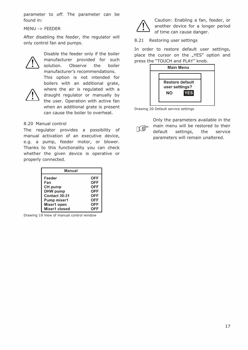
8.20 Manual control
The regulator provides a possibility of
manual activation of an executive device,
e.g. a pump, feeder motor, or blower.
Thanks to this functionality you can check
whether the given device is operative or
properly connected.
Drawing 19 View of manual control window
Caution: Enabling a fan, feeder, or
another device for a longer period
of time can cause danger.
8.21 Restoring user settings
In order to restore default user settings,
place the cursor on the „YES” option and press the “TOUCH and PLAY” knob.
Drawing 20 Default service settings
Only the parameters available in the
main menu will be restored to their
default settings, the service
parameters will remain unaltered.


REGULATOR INSTALLATION AND SERVICE SETTINGS MANUAL
ecoMAX 800, model R1

20
Boiler settings
Sernice settings
CH/DHW settings
Password 1
9 Structure - service menu
Max. DHW temp.
Increase CH to DHW
Extend DHW time
CH start temp.
CH standstill
CH stand. load DHW
Min. DHW temp.
Boiler hysteresis
Min. boiler temp.
Max. boiler temp.
Min. fan power
CH system type
Room thermostat
Out. temp. control
Heating curve
Fuel detect. time
Feed time CONTR
Extend fan time
Max. feeder temp.
Min. return temp.
Return temp. hysteresis
Return protection
Auxiliary boiler
Alarms
Boiler cooling temp.
Valve 4D
Valve 3D term.
Mixer settings 1
Integr. time-const.
Valve opening time
Mixer operat.
Min. mixer temp.
Max. mixer temp.
Proportional band
OFF
CH ON
Floor h. ON
Pump only

21
Restore serv. set.
Password 2
Boiler type
Password 3
Temp. recording
Mixer settings 2
Integr. time-const.
Valve opening time
Mixer operat.
Min. mixer temp.
Max. mixer temp.
Proportional band
OFF
CH ON
Floor h. ON
Pump only
Mixer settings 3
Integr. time-const.
Valve opening time
Mixer operat.
Min. mixer temp.
Max. mixer temp.
Proportional band
OFF
CH ON
Floor h. ON
Pump only
22
10 Hydraulic diagrams
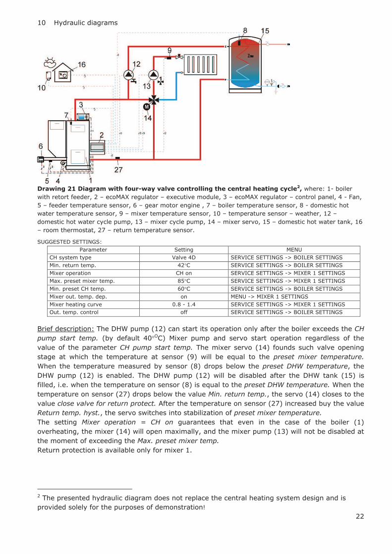
Drawing 21 Diagram with four-way valve controlling the central heating cycle2, where: 1- boiler
with retort feeder, 2 – ecoMAX regulator – executive module, 3 – ecoMAX regulator – control panel, 4 - Fan,
5 – feeder temperature sensor, 6 – gear motor engine , 7 – boiler temperature sensor, 8 - domestic hot
water temperature sensor, 9 – mixer temperature sensor, 10 – temperature sensor – weather, 12 –
domestic hot water cycle pump, 13 – mixer cycle pump, 14 – mixer servo, 15 – domestic hot water tank, 16
– room thermostat, 27 – return temperature sensor.
SUGGESTED SETTINGS:
Parameter Setting MENU
CH system type Valve 4D SERVICE SETTINGS -> BOILER SETTINGS
Min. return temp. 42°C SERVICE SETTINGS -> BOILER SETTINGS
Mixer operation CH on SERVICE SETTINGS -> MIXER 1 SETTINGS
Max. preset mixer temp. 85°C SERVICE SETTINGS -> MIXER 1 SETTINGS
Min. preset CH temp. 60°C SERVICE SETTINGS -> BOILER SETTINGS
Mixer out. temp. dep. on MENU -> MIXER 1 SETTINGS
Mixer heating curve 0.8 - 1.4 SERVICE SETTINGS -> MIXER 1 SETTINGS
Out. temp. control off SERVICE SETTINGS -> BOILER SETTINGS
Brief description: The DHW pump (12) can start its operation only after the boiler exceeds the CH
pump start temp. (by default 40°OC) Mixer pump and servo start operation regardless of the
value of the parameter CH pump start temp. The mixer servo (14) founds such valve opening
stage at which the temperature at sensor (9) will be equal to the preset mixer temperature.
When the temperature measured by sensor (8) drops below the preset DHW temperature, the
DHW pump (12) is enabled. The DHW pump (12) will be disabled after the DHW tank (15) is
filled, i.e. when the temperature on sensor (8) is equal to the preset DHW temperature. When the
temperature on sensor (27) drops below the value Min. return temp., the servo (14) closes to the
value close valve for return protect. After the temperature on sensor (27) increased buy the value
Return temp. hyst., the servo switches into stabilization of preset mixer temperature.
The setting Mixer operation = CH on guarantees that even in the case of the boiler (1)
overheating, the mixer (14) will open maximally, and the mixer pump (13) will not be disabled at
the moment of exceeding the Max. preset mixer temp.
Return protection is available only for mixer 1.
2 The presented hydraulic diagram does not replace the central heating system design and is
provided solely for the purposes of demonstration!
23
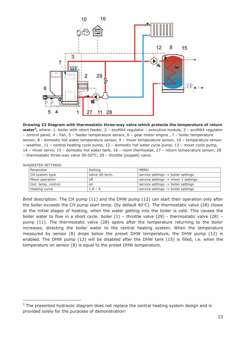
Drawing 22 Diagram with thermostatic three-way valve which protects the temperature of return
water3, where: 1- boiler with retort feeder, 2 – ecoMAX regulator – executive module, 3 – ecoMAX regulator
– control panel, 4 - Fan, 5 – feeder temperature sensor, 6 – gear motor engine , 7 – boiler temperature
sensor, 8 - domestic hot water temperature sensor, 9 – mixer temperature sensor, 10 – temperature sensor
– weather, 11 – central heating cycle pump, 12 – domestic hot water cycle pump, 13 – mixer cycle pump,
14 – mixer servo, 15 – domestic hot water tank, 16 – room thermostat, 27 – return temperature sensor, 28
– thermostatic three-way valve 50-55°C, 29 – throttle (poppet) valve.
SUGGESTED SETTINGS:
Parameter Setting MENU
CH system type Valve 3D term. service settings -> boiler settings
Mixer operation off service settings -> mixer 1 settings
Out. temp. control on service settings -> boiler settings
Heating curve 1.8 – 4 service settings -> boiler settings
Brief description: The CH pump (11) and the DHW pump (12) can start their operation only after
the boiler exceeds the CH pump start temp. (by default 40°C). The thermostatic valve (28) closes
at the initial stages of heating, when the water getting into the boiler is cold. This causes the
boiler water to flow in a short cycle: boiler (1) – throttle valve (29) - thermostatic valve (28) –
pump (11). The thermostatic valve (28) opens after the temperature returning to the boiler
increases, directing the boiler water to the central heating system. When the temperature
measured by sensor (8) drops below the preset DHW temperature, the DHW pump (12) is
enabled. The DHW pump (12) will be disabled after the DHW tank (15) is filled, i.e. when the
temperature on sensor (8) is equal to the preset DHW temperature.
3 The presented hydraulic diagram does not replace the central heating system design and is
provided solely for the purposes of demonstration!

24
Drawing 23 Diagram with a three-way thermostatic valve which protects the temperature of the
return water, and a three-way valve which feeds floor heating, as well as with two additional
mixer cycles after attachment of extension module MX.014, where 1 – boiler with retort feeder, 2 -
ecoMAX regulator - executive module, 3 - ecoMAX regulator – control panel, 4- Fan, 5 – feeder temperature
sensor, 6 – gear motor engine, 7 – boiler temperature sensor. 8 – domestic hot water temperature sensor, 9
– mixer temperature sensor, 10 – temperature sensor—weather, 11 – central heating cycle pump, 12 –
domestic hot water cycle pump, 13 – mixer cycle pump, 14 – mixer servo, 15 – domestic hot water tank, 16
– room thermostat, 17 – ecoMAX 800 regulator – mixer module MX.01. 18 – mixer servo 2, 19 – mixer
servo 3, 20 – mixer pump 2, 21 – mixer pump 3, 22 room thermostat of mixer 2, 23 – room thermostat of
mixer 3, 24 – temperature sensor – mixer 2, 35 – temperature sensor – mixer 3, 26 – external thermostat
protecting floor heating 55oC (cuts off power supply of mixer pump when the maximum temperature is
exceeded – the thermostat is not part of the ecoMAX 800 regulator set), 27 – return temperature sensor, 28
– thermostatic three-way valve 50-55°C (protecting boiler return), 30 – fluid coupling (eliminates necessity
of balancing the pumps’ flows).
SUGGESTED SETTINGS:
Parameter Setting MENU
CH system type Valve 3D term. service settings -> boiler settings
Mixer operation Floor h. ON service settings -> mixer 1 settings
Max. preset mixer temp. 45°C! service settings -> mixer 1 settings
Mixer heating curve 0.2 – 0.6 service settings -> mixer 1 settings
Mixer operation Floor h. ON service settings -> mixer 2 settings
Max. preset mixer temp. 45°C! service settings -> mixer 2 settings
Mixer heating curve 0.2 – 0.6 service settings -> mixer 2 settings
Mixer operation CH on service settings -> mixer 3 settings
Max. preset mixer temp. 85° service settings -> mixer 3 settings
Mixer heating curve 0.8 – 1.4 service settings -> mixer 3 settings
4 The presented hydraulic diagram does not replace the central heating system design and is
provided solely for the purposes of demonstration!
OPTION – available after
connecting additional
MIXER module

25
11 Technical data
Voltage 230V~; 50Hz;
Current consumed by regulator
I = 0,02 A5
Maximum rated current 6 (6) A
Regulator protection rating IP20, IP006
Ambient temperature 0...50 °C
Storage temperature 0...65°C
Relative humidity
5 - 85% without
condensation of
vapour
Measuring range of
temperature sensors CT4 0...100 °C
Measuring range of
temperature sensors CT4-P -35...40 °C
Accuracy of temperature
measurements with sensors
CT4 and CT4-P
2°C
Terminals
Screw terminal on
the mains voltage
side 2,5mm2
Screw terminals on
the control side
1,5mm2
Display Graphic 128x64
External dimensions
Control panel:
164x90x40 mm
Executive module:
140x90x65 mm
Total weight 0,5 kg
Norms PN-EN 60730-2-9
PN-EN 60730-1
Software class A
Protection class To be built into
class I devices
Table 1 Technical data
The set includes:
- boiler temperature sensor
- feeder temperature sensor
- DHW temperature sensor,
- executive module
- control panel
- connecting cable
1 piece
1 piece
1 piece
1 piece
1 piece
- panel lid
- panel hole plugs
- panel screws B3x8
1 piece
4 pcs.
2 pcs.
5 This is the current consumed by the regulator itself.
The total current consumption depends on the devices
connected to the regulator. 6 IP20 – from the front side of the executive module,
IP00 – from the side of terminals of the executive
module, detailed information presented in point 13.5
- manual
- warranty
1 piece
1 piece
12 Conditions of storage and transport
The regulator cannot be exposed to direct
effects of weather, i.e. rain and sunlight.
Storage and transport temperature cannot
exceed the range of -15…65 °C. During transport, the device cannot be
exposed to vibrations greater than those
typical of normal road transport.
13 REGULATOR INSTALLATION
13.1 Environmental conditions
On account of risk of shock, the regulator
has been designed to be used in an
environment in which dry conductive
pollutants occur (pollution level 3, acc. to
PN-EN 60730-1).
Due to the risk of fire, it is prohibited to
operate the regulator in explosive gas and
flammable dust atmosphere (e.g. coal dust).
The regulator should be separated using
appropriate enclosure.
Moreover, the regulator cannot be used in
the presence of vapour condensation, and be
exposed to water.
13.2 Installation requirements
The regulator should be installed by a
qualified and authorised fitter, in accordance
with the applicable norms and regulations.
The manufacturer bears no responsibility for
damages caused by failure to observe this
manual.
The regulator is to be built-in. The regulator
cannot be used as a stand-alone device.
The temperature of the ambient and the
fitting surface cannot exceed the range of 0 -
50˚C. The device has two-module structure which
includes control pane and executive module.
Both parts are connected with an electric
lead.
13.3 Installation of control panel
The control panel is to be enclosed on a
mounting plate. Proper thermal insulation
between hot boiler walls and the panel and
the connecting tape must be provided. The
space required for the control panel is shown
in Drawing 26 . During installation, follow the
guidelines below.
26
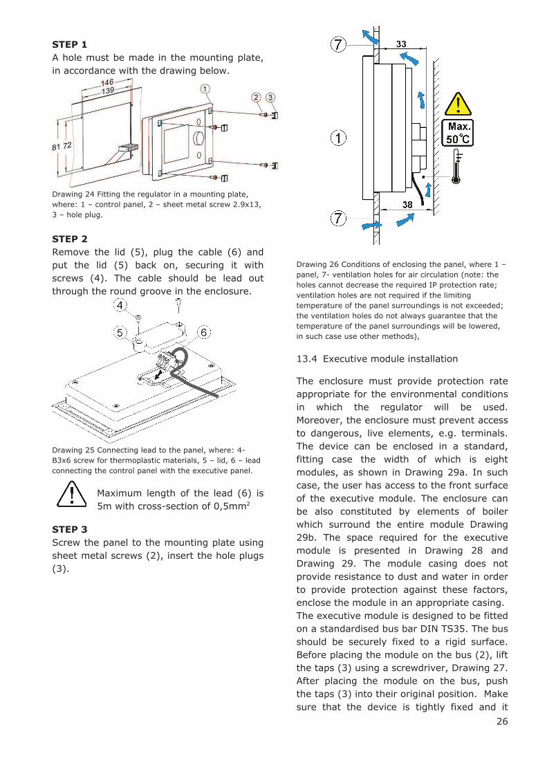
STEP 1
A hole must be made in the mounting plate,
in accordance with the drawing below.
Drawing 24 Fitting the regulator in a mounting plate,
where: 1 – control panel, 2 – sheet metal screw 2.9x13,
3 – hole plug.
STEP 2
Remove the lid (5), plug the cable (6) and
put the lid (5) back on, securing it with
screws (4). The cable should be lead out
through the round groove in the enclosure.
Drawing 25 Connecting lead to the panel, where: 4-
B3x6 screw for thermoplastic materials, 5 – lid, 6 – lead
connecting the control panel with the executive panel.
Maximum length of the lead (6) is
5m with cross-section of 0,5mm2
STEP 3
Screw the panel to the mounting plate using
sheet metal screws (2), insert the hole plugs
(3).
Drawing 26 Conditions of enclosing the panel, where 1 –
panel, 7- ventilation holes for air circulation (note: the
holes cannot decrease the required IP protection rate;
ventilation holes are not required if the limiting
temperature of the panel surroundings is not exceeded;
the ventilation holes do not always guarantee that the
temperature of the panel surroundings will be lowered,
in such case use other methods),
13.4 Executive module installation
The enclosure must provide protection rate
appropriate for the environmental conditions
in which the regulator will be used.
Moreover, the enclosure must prevent access
to dangerous, live elements, e.g. terminals.
The device can be enclosed in a standard,
fitting case the width of which is eight
modules, as shown in Drawing 29a. In such
case, the user has access to the front surface
of the executive module. The enclosure can
be also constituted by elements of boiler
which surround the entire module Drawing
29b. The space required for the executive
module is presented in Drawing 28 and
Drawing 29. The module casing does not
provide resistance to dust and water in order
to provide protection against these factors,
enclose the module in an appropriate casing.
The executive module is designed to be fitted
on a standardised bus bar DIN TS35. The bus
should be securely fixed to a rigid surface.
Before placing the module on the bus (2), lift
the taps (3) using a screwdriver, Drawing 27.
After placing the module on the bus, push
the taps (3) into their original position. Make
sure that the device is tightly fixed and it
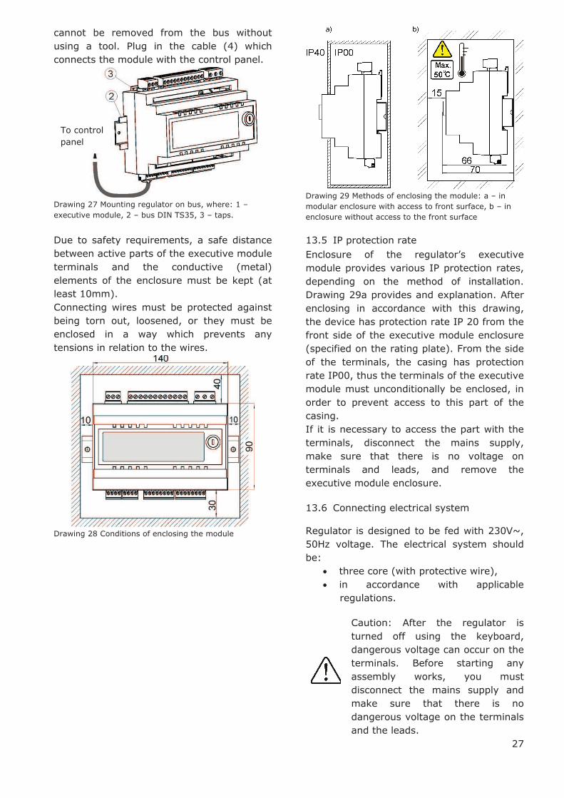
27
cannot be removed from the bus without
using a tool. Plug in the cable (4) which
connects the module with the control panel.
Drawing 27 Mounting regulator on bus, where: 1 –
executive module, 2 – bus DIN TS35, 3 – taps.
Due to safety requirements, a safe distance
between active parts of the executive module
terminals and the conductive (metal)
elements of the enclosure must be kept (at
least 10mm).
Connecting wires must be protected against
being torn out, loosened, or they must be
enclosed in a way which prevents any
tensions in relation to the wires.
Drawing 28 Conditions of enclosing the module
Drawing 29 Methods of enclosing the module: a – in
modular enclosure with access to front surface, b – in
enclosure without access to the front surface
13.5 IP protection rate
Enclosure of the regulator’s executive module provides various IP protection rates,
depending on the method of installation.
Drawing 29a provides and explanation. After
enclosing in accordance with this drawing,
the device has protection rate IP 20 from the
front side of the executive module enclosure
(specified on the rating plate). From the side
of the terminals, the casing has protection
rate IP00, thus the terminals of the executive
module must unconditionally be enclosed, in
order to prevent access to this part of the
casing.
If it is necessary to access the part with the
terminals, disconnect the mains supply,
make sure that there is no voltage on
terminals and leads, and remove the
executive module enclosure.
13.6 Connecting electrical system
Regulator is designed to be fed with 230V~,
50Hz voltage. The electrical system should
be:
· three core (with protective wire),
· in accordance with applicable
regulations.
Caution: After the regulator is
turned off using the keyboard,
dangerous voltage can occur on the
terminals. Before starting any
assembly works, you must
disconnect the mains supply and
make sure that there is no
dangerous voltage on the terminals
and the leads.
To control
panel

28
Diagram of electrical connections is
presented in Drawing 31. The connection
wires should not have contact with surfaces
of room temperature exceeding the nominal
temperature of their operation.
Terminals number 1-15 are intended only for
connecting devices with mains supply
230V~.
Terminals 16-31 are intended for cooperation
with low voltage devices (below 12 V).
Connecting mains supply 230V~ to
terminals 16-31 and to
transmission connectors RS485 will
damage the regulator and creates
risk of an electric shock.
Tips of the connected wires, especially power
leads, must be secured against splitting by
means of insulated clamp sleeves, in
accordance with the drawing below:
Drawing 30 Securing wire tips: a) right, b) wrong
The feeder cable should be connected to the
terminals marked with an arrow.
13.7 Protective connections
The protective conductor of the feeder cable
should be connected to a neutral strip
contacted with the metal casing of the
regulator. The fitting should be connected to
the regulator terminal marked with symbol
and with grounding terminals of the
devices connected to the regulator (Drawing
31).
Drawing 31 Diagram of electric connections with
external devices, where: T1 – boiler temperature sensor
CT4, T2 fuel feeder temperature sensor CT4, T3 –
domestic hot water temperature sensor, T4 – mixer 1
temperature sensor, CT4, T5 – weather temperature
sensor type CT4-P, T6 – temperature sensor for water
returning to the boiler (optional), U3 – relay for
connecting reserve boiler or alarm, T – room
thermostat, P – boiler control panel, MX.01 – extension
module (option, tow additional heating cycles), ! -
connect with two wires – do not connect with four wires.
230V~ - feeding cable, STB – safety temperature limiter
(disconnects feeder and airflow), W – fan, PO – fuel
feeder motor, PCO – central heating pump, PCW –
domestic hot water pump, PM – mixer pump, SM –
mixer servo, LZ – neutral strip, UZ – earthing of the
regulator metal casing.
The regulator must be equipped
with a set of pins, inserted in the
connectors for feeding 230V~
devices

29
13.8 Connecting temperature sensors
The regulator cooperates only CT4 sensors.
It is forbidden to use different sensors.
Sensor leads can be extended with wires
with section of at least 0,5mm2. Total length
of the sensor leads cannot exceed 15 m.
The boiler temperature sensor should be
fitted in the thermometric pipe, situated in
the boiler shell. The feeder temperature
sensor must be fitted on the surface of the
feeder screw pipe. The domestic hot water
temperature sensor - in the thermometric
pipe welded into the tank. It is best to fit the
mixer temperature sensor in a tube (sleeve)
placed in the stream of water flowing in the
pipe, but it is also possible to clip it onto the
pipe, covering the sensor and the pipe with
thermal insulation.
The sensors must be secured
against coming loose from the
measured surfaces.
Good thermal contact between the sensors
and the measured surface must be ensured.
For this purpose, use thermally conductive
paste. Do not pour oil or water over the
sensors.
The sensor cables should be separated from
mains leads. Otherwise, the temperature
indications can be incorrect. Minimum
distance between these leads should be at
least 10 cm.
The sensor leads cannot have contact with
hot elements of the boiler and heating
system. The temperature sensors’ leads are resistant to temperature up to 100°C.
13.9 Connecting weather sensor
The regulator cooperates only with a weather
sensor of the CT4-P type. The sensor should
be installed on the coldest wall of the
building, usually this is the northern wall,
under a roof. The sensor should not be
exposed to direct sunlight and rain. The
sensor should be fitted at least 2m above the
ground, far from windows, chimneys and
other heat sources which could disturb the
temperature measurement (at least 1,5 m).
Connect the sensor using cable of 0,5 mm2
cross-section, up to 25 m long. Bias of the
leads is insignificant. Connect the other end
of the cable to the regulator, as shown in
Drawing 31.
Attach the sensor to the wall using tackbolts.
To access the tackbolts holes, unscrew the
sensor lid.
Drawing 32 Connecting weather senor CT4-P, the sensor
is an optional equipment.
13.10 Checking temperature sensors
The CT4 temperature sensor can be
controlled by measuring its resistance in a
given temperature. In the case of finding
significant differences between the value of
measured resistance and the values
presented in the table below, the sensor
must be changed.
CT4
Ambient
temp. °C
Min.
Ω
Nom.
Ω
Max
Ω
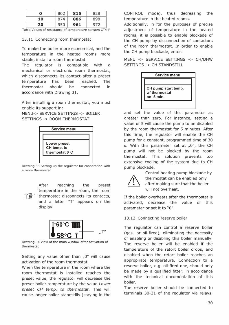
0 802 815 828
10 874 886 898
20 950 961 972
25 990 1000 1010
30 1029 1040 1051
40 1108 1122 1136
50 1192 1209 1225
60 1278 1299 1319
70 1369 1392 1416
80 1462 1490 1518
90 1559 1591 1623
100 1659 1696 1733
Table Values of resistance of temperature sensors CT4
CT4-P (weather)
Temp.
°C
Min.
Ω
Nom.
Ω
Max
Ω
-30 609 624 638
-20 669 684 698
-10 733 747 761
30
0 802 815 828
10 874 886 898
20 950 961 972
Table Values of resistance of temperature sensors CT4-P
13.11 Connecting room thermostat
To make the boiler more economical, and the
temperature in the heated rooms more
stable, install a room thermostat.
The regulator is compatible with a
mechanical or electronic room thermostat,
which disconnects its contact after a preset
temperature has been reached. The
thermostat should be connected in
accordance with Drawing 31.
After installing a room thermostat, you must
enable its support in:
MENU-> SERVICE SETTINGS -> BOILER
SETTINGS -> ROOM THERMOSTAT
Drawing 33 Setting up the regulator for cooperation with
a room thermostat
After reaching the preset
temperature in the room, the room
thermostat disconnects its contacts,
and a letter “T” appears on the
display
Drawing 34 View of the main window after activation of
thermostat
Setting any value other than „0” will cause
activation of the room thermostat.
When the temperature in the room where the
room thermostat is installed reaches the
preset value, the regulator will decrease the
preset boiler temperature by the value Lower
preset CH temp. to thermostat. This will
cause longer boiler standstills (staying in the
CONTROL mode), thus decreasing the
temperature in the heated rooms.
Additionally, in for the purposes of precise
adjustment of temperature in the heated
rooms, it is possible to enable blockade of
the CH pump by disconnection of contactors
of the room thermostat. In order to enable
the CH pump blockade, enter:
MENU -> SERVICE SETTINGS -> CH/DHW
SETTINGS -> CH STANDSTILL
and set the value of this parameter as
greater than zero. For instance, setting a
value of 5 will cause the pump to be disabled
by the room thermostat for 5 minutes. After
this time, the regulator will enable the CH
pump for a constant, programmed time of 30
s. With this parameter set at „0”, the CH
pump will not be blocked by the room
thermostat. This solution prevents too
extensive cooling of the system due to CH
pump blockade.
Central heating pump blockade by
thermostat can be enabled only
after making sure that the boiler
will not overheat.
If the boiler overheats after the thermostat is
activated, decrease the value of this
parameter or set it to “0”.
13.12 Connecting reserve boiler
The regulator can control a reserve boiler
(gas- or oil-fired), eliminating the necessity
of enabling or disabling this boiler manually.
The reserve boiler will be enabled if the
temperature of the retort boiler drops, and
disabled when the retort boiler reaches an
appropriate temperature. Connection to a
reserve boiler, e.g. oil-fired one, should only
be made by a qualified fitter, in accordance
with the technical documentation of this
boiler.
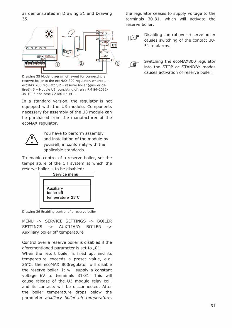
The reserve boiler should be connected to
terminals 30-31 of the regulator via relays,
,,T”
31
as demonstrated in Drawing 31 and Drawing
35.
Drawing 35 Model diagram of layout for connecting a
reserve boiler to the ecoMAX 800 regulator, where: 1 –
ecoMAX 700 regulator, 2 – reserve boiler (gas- or oil-
fired), 3 – Module U3, consisting of relay RM 84-2012-
35-1006 and base GZT80 RELPOL.
In a standard version, the regulator is not
equipped with the U3 module. Components
necessary for assembly of the U3 module can
be purchased from the manufacturer of the
ecoMAX regulator.
You have to perform assembly
and installation of the module by
yourself, in conformity with the
applicable standards.
To enable control of a reserve boiler, set the
temperature of the CH system at which the
reserve boiler is to be disabled:
Drawing 36 Enabling control of a reserve boiler
MENU -> SERVICE SETTINGS -> BOILER
SETTINGS -> AUXILIARY BOILER ->
Auxiliary boiler off temperature
Control over a reserve boiler is disabled if the
aforementioned parameter is set to „0”.
When the retort boiler is fired up, and its
temperature exceeds a preset value, e.g.
25oC, the ecoMAX 800regulator will disable
the reserve boiler. It will supply a constant
voltage 6V to terminals 31-31. This will
cause release of the U3 module relay coil,
and its contacts will be disconnected. After
the boiler temperature drops below the
parameter auxiliary boiler off temperature,
the regulator ceases to supply voltage to the
terminals 30-31, which will activate the
reserve boiler.
Disabling control over reserve boiler
causes switching of the contact 30-
31 to alarms.
Switching the ecoMAX800 regulator
into the STOP or STANDBY modes
causes activation of reserve boiler.
32
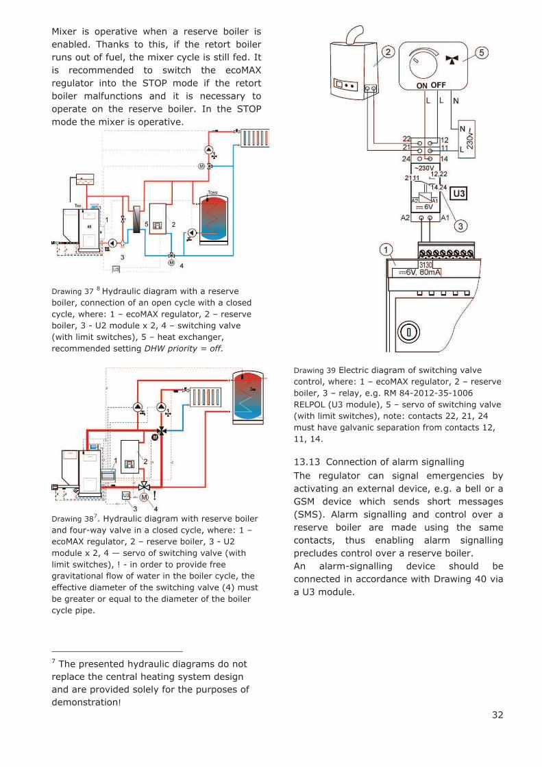
Mixer is operative when a reserve boiler is
enabled. Thanks to this, if the retort boiler
runs out of fuel, the mixer cycle is still fed. It
is recommended to switch the ecoMAX
regulator into the STOP mode if the retort
boiler malfunctions and it is necessary to
operate on the reserve boiler. In the STOP
mode the mixer is operative.
Drawing 37 8 Hydraulic diagram with a reserve
boiler, connection of an open cycle with a closed
cycle, where: 1 – ecoMAX regulator, 2 – reserve
boiler, 3 - U2 module x 2, 4 – switching valve
(with limit switches), 5 – heat exchanger,
recommended setting DHW priority = off.
Drawing 38
7. Hydraulic diagram with reserve boiler
and four-way valve in a closed cycle, where: 1 –
ecoMAX regulator, 2 – reserve boiler, 3 - U2
module x 2, 4 — servo of switching valve (with
limit switches), ! - in order to provide free
gravitational flow of water in the boiler cycle, the
effective diameter of the switching valve (4) must
be greater or equal to the diameter of the boiler
cycle pipe.
7 The presented hydraulic diagrams do not
replace the central heating system design
and are provided solely for the purposes of
demonstration!
Drawing 39 Electric diagram of switching valve
control, where: 1 – ecoMAX regulator, 2 – reserve
boiler, 3 – relay, e.g. RM 84-2012-35-1006
RELPOL (U3 module), 5 – servo of switching valve
(with limit switches), note: contacts 22, 21, 24
must have galvanic separation from contacts 12,
11, 14.
13.13 Connection of alarm signalling
The regulator can signal emergencies by
activating an external device, e.g. a bell or a
GSM device which sends short messages
(SMS). Alarm signalling and control over a
reserve boiler are made using the same
contacts, thus enabling alarm signalling
precludes control over a reserve boiler.
An alarm-signalling device should be
connected in accordance with Drawing 40 via
a U3 module.

33
Drawing 40 Connecting an external alarming device,
where: 1 – ecoMAX800 regulator, 2 – external alarming
device, 3 – U3 Module, consisting of relay RM 84-2012-
35-1006 RELPOL and base GZT80 RELPOL.
If the regulator is to control an
external alarming device, you must
set the parameter auxiliary boiler off
temperature to “0”
MENU -> SERVICE SETTINGS ->
BOILER SETTINGS -> AUXILIARY
BOILER -> Auxiliary boiler off
temperature
To guarantee proper operation, set an
appropriate value of the parameter Active
alarms signalling code in:
MENU -> SERVICE SETTINGS -> BOILER
SETTINGS -> ALARMS -> Active alarms
signal code
Choosing a value of 31 causes voltage to be
fed to contact 30-31 if any alarm occurs.
After setting this parameter to „0”, the
regulator will not supply voltage in the case
of any alarm.
The 30-31 contact can be configured so that
voltage was supplied there only if one or
more alarms occur. The value to which this
parameter should be set for individual alarms
is presented in the following table:
No fuel
Boiler
overh
eate
d
Fla
me r
evers
ed
CH
boiler
tem
pera
ture
sensor
dam
age
Feeder
tem
pera
ture
sensor
dam
age
AL 1 AL 2 AL 3 AL 4 AL 5
1 2 4 8 16
Example: if you set the value of the
parameter to „8”, the voltage will be supplied
to the contact only if alarm AL4 occurs.
Setting “1” will cause the contact to signalize
only alarm “1”. Should the contact signalize
several alarms, e.g. AL2 and AL4, sum up
the values corresponding to individual
alarms, i.e. you should set 2 + 8 = 10. If
alarms AL1, AL2 and AL3 are to be signalled,
set the parameter to “7”, as 1 + 2 + 4 = 7.
13.14 Connecting mixer
The regulator cooperates only with servos of
mixing valves equipped with limit switches. It
is prohibited to use different servos.
Permitted servos are those which make a full
revolution in 30 - 255 s.
Description of connecting a mixer:
- disable power supply to the regulator,
- determine the direction in which the servo
opens/closes and make an electric
connection between the mixer and the
regulator, in accordance with Drawing 31,
and with the documentation provided by the
valve servo manufacturer (do not confuse
the valve direction of opening with the
direction of closing). 0
- connect mixer temperature sensor and
mixer pump.
- turn the regulator on and set an
appropriate valve full opening time in the
mixer service settings, in accordance with
the servo manual.
- disable and enable power supply to the
regulator, wait until the servo is calibrated.
During the calibration, the servo is closed by
the valve full opening time. Calibration is
signalled in the MENU Information – mixer
info by sign “CAL”.
- make sure that the servo opens in the
correct direction. To do so, open MENU
Information and go to tab info-mixer, or
enter the regulator manual control. If the
mixer does not open in the correct direction,
change the electric connection.
- disable and enable power supply to the
regulator, wait until the servo is calibrated.
- set the mixer parameters in accordance
with point 16.
34
13.15 Connecting temperature limiter
In order to prevent the boiler from
overheating due to the regulator
malfunction, an STB safety temperature
limiter, or any other appropriate for the
given boiler and heating system, should be
fitted.
The STB limiter can be connected to
terminals 1-2, as specified in Drawing 31.
When the limiter is activated, the airflow and
fuel feeder motor are disconnected.
The temperature limiter must
have nominal operating voltage of
at least ~230V, and it should have
the applicable permits.
If the limiter is not connected to terminals 1-
2, a bridge should be made. The bridge
should be made of wire the section of which
is at least 0,75 mm2, with insulation thick
enough to comply with the boiler safety
requirements.
The current regulations demand
that a safety temperature limiter
is used.
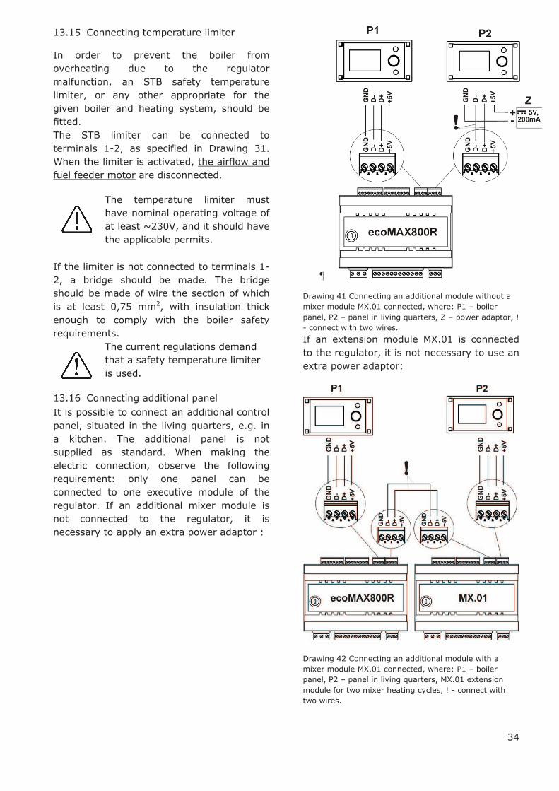
13.16 Connecting additional panel
It is possible to connect an additional control
panel, situated in the living quarters, e.g. in
a kitchen. The additional panel is not
supplied as standard. When making the
electric connection, observe the following
requirement: only one panel can be
connected to one executive module of the
regulator. If an additional mixer module is
not connected to the regulator, it is
necessary to apply an extra power adaptor :
¶
Drawing 41 Connecting an additional module without a
mixer module MX.01 connected, where: P1 – boiler
panel, P2 – panel in living quarters, Z – power adaptor, !
- connect with two wires.
If an extension module MX.01 is connected
to the regulator, it is not necessary to use an
extra power adaptor:
Drawing 42 Connecting an additional module with a
mixer module MX.01 connected, where: P1 – boiler
panel, P2 – panel in living quarters, MX.01 extension
module for two mixer heating cycles, ! - connect with
two wires.
35
Maximum length of leads to the additional
power cannot exceed 30m, and their cross
section should be at least 0,5 mm2.
14 BOILER SERVICE SETTINGS
14.1 Installation type
If the boiler cooperates with a four-way valve
and valve servo, and a return temperature
sensor is connected, you can activate a
function of safeguard against cold water
returning to the boiler. To do so, select the
option „Valve 4D”. Otherwise, or if the boiler
return is safeguarded by a thermostatic
valve, choose the option “Valve 3D therm.”
Then, the regulator does not influence the
safeguards of the boiler return.
Caution: the return protection function is
active only for mixer 1 cycle.
Drawing 43 Installation type
Description of the regulator’s operation in
return protection can be found in point 9.
If the return temperature sensor T6
is disconnected or damaged, the
regulator will automatically switch
into the option Valve 3D therm.
14.2 Room thermostat of the boiler
This parameter allows to determine decrease
in the preset boiler temperature due to
disconnection of room thermostat contacts.
Detailed information can be found in point
13.11
14.3 Boiler weather control
This parameter allows to disable weather
control of the boiler which calculated the
preset boiler temperature on the basis of a
weather sensor’s indications. Detailed
information can be found in point 8.16 and
13.9.
14.4 Heating curve
This parameters allows selection of
appropriate heating curve. Detailed
information can be found in point 8.16.
Drawing 44 Selection of the boiler’s heating curve,
where: 1.4 – selected heating curve, 59 – temperature
calculated from the heating curve for the current
outdoor temperature measured by the CT4-P sensor.
14.5 Boiler hysteresis
This parameter determines the temperature
at which the boiler returns from the
CONTROL mode to the OPERATION mode.
The regulator returns to the OPERATION
mode at the temperature preset CH
temperature – boiler hysteresis.
14.6 Minimum preset boiler temperature
This parameter can be used to prevent the
user from setting too low preset boiler
temperature. If the boiler operates at too low
temperature, it can cause its rapid damage,
corrosion, soiling, etc. Additionally, the
regulator will accept this temperature instead
of the preset boiler temperature which
results from decreases on account of time
periods, or room thermostat.
Set the value in accordance with the
boiler manufacturer’s
recommendations
14.7 Maximum preset boiler temperature
This parameter can be used to prevent the
user from setting too high preset boiler
temperature.
If the heating curve temperature or the
preset DHW temperature are higher than the
Max. preset CH temp.., the regulator will
adopt the Max. preset CH temp. as the
preset temperature.
Set the value in accordance with
the boiler manufacturer’s
recommendations
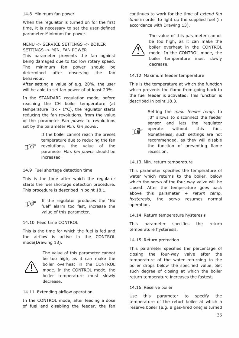
36
14.8 Minimum fan power
When the regulator is turned on for the first
time, it is necessary to set the user-defined
parameter Minimum fan power.
MENU -> SERVICE SETTINGS -> BOILER
SETTINGS -> MIN. FAN POWER
This parameter prevents the fan against
being damaged due to too low rotary speed.
The minimum fan power should be
determined after observing the fan
behaviour.
After setting a value of e.g. 20%, the user
will be able to set fan power of at least 20%.
In the STANDARD regulation mode, before
reaching the CH boiler temperature (at
temperature Tzk - 1°C), the regulator starts
reducing the fan revolutions, from the value
of the parameter Fan power to revolutions
set by the parameter Min. fan power.
If the boiler cannot reach the preset
temperature due to reducing the fan
revolutions, the value of the
parameter Min. fan power should be
increased.
14.9 Fuel shortage detection time
This is the time after which the regulator
starts the fuel shortage detection procedure.
This procedure is described in point 18.1.
If the regulator produces the “No
fuel” alarm too fast, increase the
value of this parameter.
14.10 Feed time CONTROL
This is the time for which the fuel is fed and
the airflow is active in the CONTROL
mode(Drawing 13).
The value of this parameter cannot
be too high, as it can make the
boiler overheat in the CONTROL
mode. In the CONTROL mode, the
boiler temperature must slowly
decrease.
14.11 Extending airflow operation
In the CONTROL mode, after feeding a dose
of fuel and disabling the feeder, the fan
continues to work for the time of extend fan
time in order to light up the supplied fuel (in
accordance with Drawing 13).
The value of this parameter cannot
be too high, as it can make the
boiler overheat in the CONTROL
mode. In the CONTROL mode, the
boiler temperature must slowly
decrease.
14.12 Maximum feeder temperature
This is the temperature at which the function
which prevents the flame from going back to
the fuel feeder is activated. This function is
described in point 18.3.
Setting the max. feeder temp. to
„0” allows to disconnect the feeder
sensor and lets the regulator
operate without this fuel.
Nonetheless, such settings are not
recommended, as they will disable
the function of preventing flame
recession.
14.13 Min. return temperature
This parameter specifies the temperature of
water which returns to the boiler, below
which the servo of the four-way valve will be
closed. After the temperature goes back
above this parameter + return temp.
hysteresis, the servo resumes normal
operation.
14.14 Return temperature hysteresis
This parameter specifies the return
temperature hysteresis.
14.15 Return protection
This parameter specifies the percentage of
closing the four-way valve after the
temperature of the water returning to the
boiler drops below the specified value. Set
such degree of closing at which the boiler
return temperature increases the fastest.
14.16 Reserve boiler
Use this parameter to specify the
temperature of the retort boiler at which a
reserve boiler (e.g. a gas-fired one) is turned
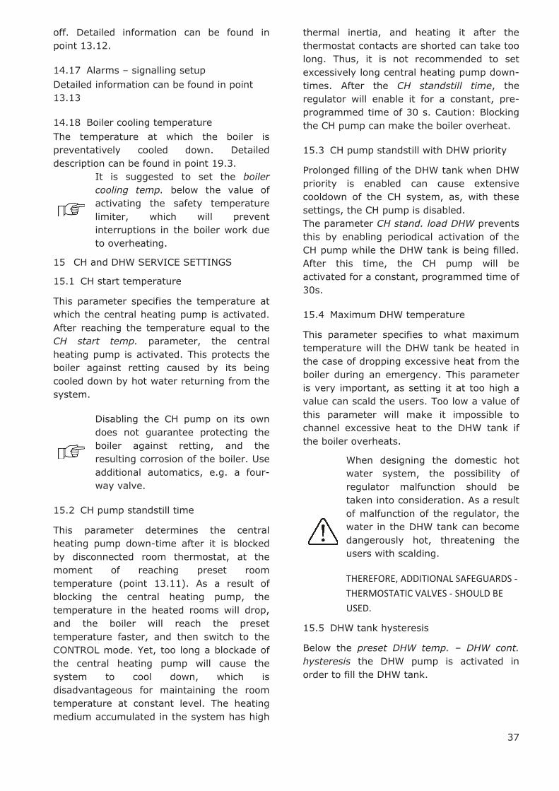
37
off. Detailed information can be found in
point 13.12.
14.17 Alarms – signalling setup
Detailed information can be found in point
13.13
14.18 Boiler cooling temperature
The temperature at which the boiler is
preventatively cooled down. Detailed
description can be found in point 19.3.
It is suggested to set the boiler
cooling temp. below the value of
activating the safety temperature
limiter, which will prevent
interruptions in the boiler work due
to overheating.
15 CH and DHW SERVICE SETTINGS
15.1 CH start temperature
This parameter specifies the temperature at
which the central heating pump is activated.
After reaching the temperature equal to the
CH start temp. parameter, the central
heating pump is activated. This protects the
boiler against retting caused by its being
cooled down by hot water returning from the
system.
Disabling the CH pump on its own
does not guarantee protecting the
boiler against retting, and the
resulting corrosion of the boiler. Use
additional automatics, e.g. a four-
way valve.
15.2 CH pump standstill time
This parameter determines the central
heating pump down-time after it is blocked
by disconnected room thermostat, at the
moment of reaching preset room
temperature (point 13.11). As a result of
blocking the central heating pump, the
temperature in the heated rooms will drop,
and the boiler will reach the preset
temperature faster, and then switch to the
CONTROL mode. Yet, too long a blockade of
the central heating pump will cause the
system to cool down, which is
disadvantageous for maintaining the room
temperature at constant level. The heating
medium accumulated in the system has high
thermal inertia, and heating it after the
thermostat contacts are shorted can take too
long. Thus, it is not recommended to set
excessively long central heating pump down-
times. After the CH standstill time, the
regulator will enable it for a constant, pre-
programmed time of 30 s. Caution: Blocking
the CH pump can make the boiler overheat.
15.3 CH pump standstill with DHW priority
Prolonged filling of the DHW tank when DHW
priority is enabled can cause extensive
cooldown of the CH system, as, with these
settings, the CH pump is disabled.
The parameter CH stand. load DHW prevents
this by enabling periodical activation of the
CH pump while the DHW tank is being filled.
After this time, the CH pump will be
activated for a constant, programmed time of
30s.
15.4 Maximum DHW temperature
This parameter specifies to what maximum
temperature will the DHW tank be heated in
the case of dropping excessive heat from the
boiler during an emergency. This parameter
is very important, as setting it at too high a
value can scald the users. Too low a value of
this parameter will make it impossible to
channel excessive heat to the DHW tank if
the boiler overheats.
When designing the domestic hot
water system, the possibility of
regulator malfunction should be
taken into consideration. As a result
of malfunction of the regulator, the
water in the DHW tank can become
dangerously hot, threatening the
users with scalding.
THEREFORE, ADDITIONAL SAFEGUARDS -
THERMOSTATIC VALVES - SHOULD BE
USED.
15.5 DHW tank hysteresis
Below the preset DHW temp. – DHW cont.
hysteresis the DHW pump is activated in
order to fill the DHW tank.

38
After setting a low value, the DHW
pump will be activated faster after
the DHW temperature drops.
15.6 Increase in boiler temperature an
account of DHW and Mixer
This parameter specifies by how many
degrees will the preset CH temperature be
increased in order to fill the DHW tank and
the mixer cycle. Yet, this action will be
performed only when such need arises. When
the preset boiler temperature is high enough,
the regulator will not change it for the
purposes of filling the domestic hot water
tank or the mixer cycle.
Increasing the preset boiler
temperature for the time of filling
the domestic hot water tank is
signalled by letter „C” in the main
display window
15.7 Extending DHW pump
After filling the DHW tank and disabling the
DHW pump, there is often a problem of the
boiler overheating. It occurs if the preset
domestic hot water temperature is higher
than the preset boiler temperature. In
particular, this problem occurs in the DHW
pump mode: SUMMER, when the CH pump is
disabled. In order to cool the boiler down,
operation of the DHW pump can be extended
by the time of Extend DHW time.
It is not recommended to set the
time of Extend DHW time to a value
different than zero if the preset
DHW temperature is higher than the
preset boiler temperature.
16 MIXER SERVICE SETTINGS
16.1 MIXER OPERATION
The following options are available:
OFF – mixer servo and mixer pump are
inoperative
CH ON - choose this option if the mixer cycle
feeds radiator system of central heating. The
maximum temperature of mixer cycle is
unlimited, the mixer is fully opened during
alarms, e.g. boiler overheat. Caution: Do not
enable this option if the system is made of
pipes vulnerable to high temperature; in
such case, we recommend setting the mixer
to FLOOR h.ON.
FLOOR h.ON - choose this option if the
mixer cycle feeds a floor system. The
maximum temperature of the mixer cycle is
limited to the parameter max. mixer temp.
Caution: after choosing the option on FLOOR,
set the parameter max. mixer temp. to such
value that the floor would not be damaged,
and the floor heating users would not be
burned.
Pump only – if the servo is damaged, you
can enable control of only the mixer pump.
In this case, the head of the mixer valve
must be adjusted manually. At the moment
of exceeding the max. mixer temp., the
mixer pumps are disabled, and after the
temperature drops – they are enabled again.
16.2 Max. preset mixer temperature
This parameter serves two purposes:
- This parameter can be used to prevent the
user from setting too high preset mixer
temperature. Additionally, the regulator will
adopt this temperature instead of the preset
temperature resulting from weather control,
if it is higher than max. mixer temp.
- if the parameter mixer operation = FLOOR
h.ON is enabled, it is additionally the limit
temperature of the mixer, at which the mixer
pump is disabled.
For floor heating, set the value
within the range of 45°C - 50°C,
unless the manufacturer of the
floor materials or the designer of
the CH system specified otherwise.
16.3 MIN. preset mixer temperature
This parameter can be used to prevent the
user from setting too low preset mixer
temperature.
If the mixer preset temperature (e.g. as a
result of night-time decreases) is lower than
the value Min. preset mixer temp., the
regulator will assume the Min. preset mixer
temp. as the preset temperature.
16.4 Range of proportionality
Caution: it is recommended not to
modify this parameter.

39
This is the mixer step value. Increasing its
value will speed up reaching of the preset
mixer temperature, yet too high a value of
this parameter will cause over-regulation of
temperature and unnecessary movement of
the servo, thus shortening its life-span.
It is recommended to set this parameter
within the range of 2 – 6 [by default: 3].
16.5 Integration time constant
Caution: it is recommended not to
modify this parameter.
This parameter influences the mixer
standstill time if the temperature measured
by the mixer sensor is close to the preset
mixer temperature. Greater value will cause
longer standstills of the servo. Too high a
value extends the time by which the servo
can find the preset temperature. Setting too
low values can cause over-regulation of
temperature and faster wear of the servo.
It is recommended to set this parameter
within the range of 80 – 140 [by default:
110].
16.6 Valve opening time
Enter the time of full valve opening, which
can be found in the valve servo
documentation.
16.7 Increase in boiler temperature on account of MIXER
If the preset boiler temperature is lower than
the preset mixer temperature, the regulator
shall automatically assume the preset boiler
temperature equal to the preset mixer
temperature plus value of the parameter
increase preset CH temp. to DHW.
This parameter can be found in MENU ->
SERVICE SETTINGS -> CH/DHW SETTINGS
17 RESTORING SERVICE SETTINGS
In order to restore default service settings,
place the cursor on the „YES” option and
press the “TOUCH and PLAY” knob.
Drawing 45 Default service settings
Restoration of the factory settings
will also restore user settings.
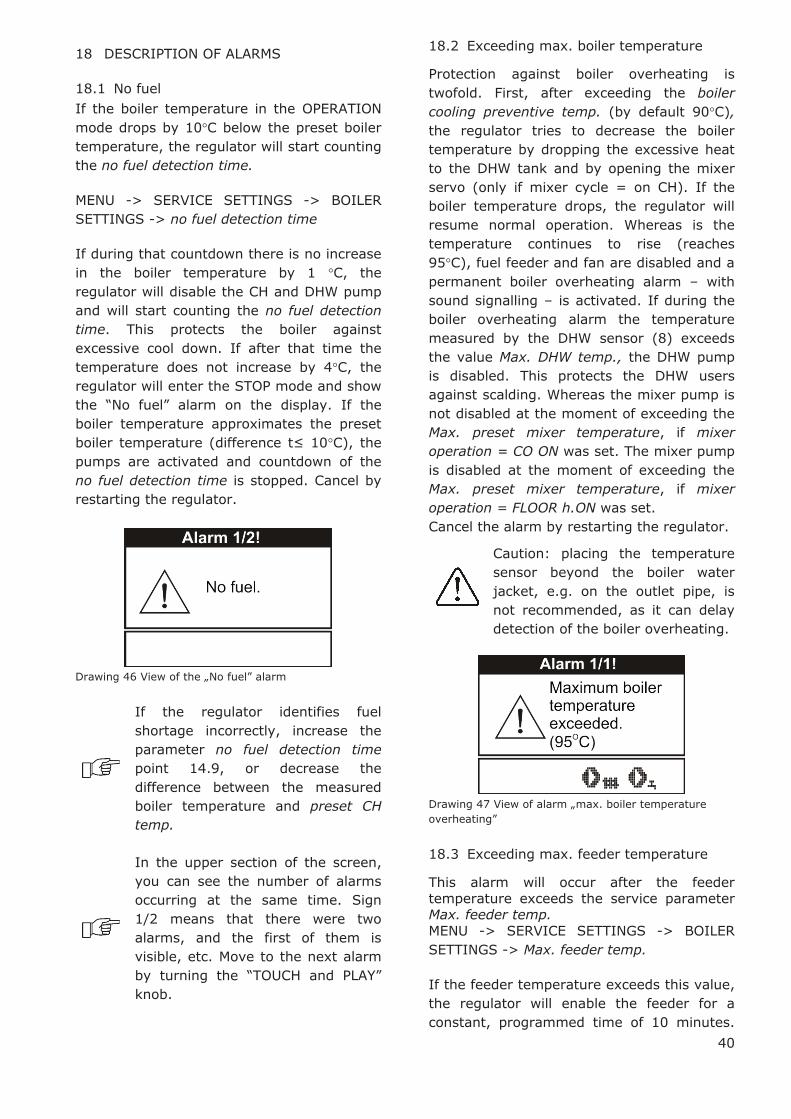
40
18 DESCRIPTION OF ALARMS
18.1 No fuel
If the boiler temperature in the OPERATION
mode drops by 10°C below the preset boiler
temperature, the regulator will start counting
the no fuel detection time.
MENU -> SERVICE SETTINGS -> BOILER
SETTINGS -> no fuel detection time
If during that countdown there is no increase
in the boiler temperature by 1 °C, the
regulator will disable the CH and DHW pump
and will start counting the no fuel detection
time. This protects the boiler against
excessive cool down. If after that time the
temperature does not increase by 4°C, the
regulator will enter the STOP mode and show
the “No fuel” alarm on the display. If the
boiler temperature approximates the preset
boiler temperature (difference t≤ 10°C), the
pumps are activated and countdown of the
no fuel detection time is stopped. Cancel by
restarting the regulator.
Drawing 46 View of the „No fuel” alarm
If the regulator identifies fuel
shortage incorrectly, increase the
parameter no fuel detection time
point 14.9, or decrease the
difference between the measured
boiler temperature and preset CH
temp.
In the upper section of the screen,
you can see the number of alarms
occurring at the same time. Sign
1/2 means that there were two
alarms, and the first of them is
visible, etc. Move to the next alarm
by turning the “TOUCH and PLAY”
knob.
18.2 Exceeding max. boiler temperature
Protection against boiler overheating is
twofold. First, after exceeding the boiler
cooling preventive temp. (by default 90°C),
the regulator tries to decrease the boiler
temperature by dropping the excessive heat
to the DHW tank and by opening the mixer
servo (only if mixer cycle = on CH). If the
boiler temperature drops, the regulator will
resume normal operation. Whereas is the
temperature continues to rise (reaches
95°C), fuel feeder and fan are disabled and a
permanent boiler overheating alarm – with
sound signalling – is activated. If during the
boiler overheating alarm the temperature
measured by the DHW sensor (8) exceeds
the value Max. DHW temp., the DHW pump
is disabled. This protects the DHW users
against scalding. Whereas the mixer pump is
not disabled at the moment of exceeding the
Max. preset mixer temperature, if mixer
operation = CO ON was set. The mixer pump
is disabled at the moment of exceeding the
Max. preset mixer temperature, if mixer
operation = FLOOR h.ON was set.
Cancel the alarm by restarting the regulator.
Caution: placing the temperature
sensor beyond the boiler water
jacket, e.g. on the outlet pipe, is
not recommended, as it can delay
detection of the boiler overheating.
Drawing 47 View of alarm „max. boiler temperature
overheating”
18.3 Exceeding max. feeder temperature
This alarm will occur after the feeder
temperature exceeds the service parameter Max. feeder temp.
MENU -> SERVICE SETTINGS -> BOILER
SETTINGS -> Max. feeder temp.
If the feeder temperature exceeds this value,
the regulator will enable the feeder for a
constant, programmed time of 10 minutes.

41
After this time, the airflow is disabled and
the pumps are enabled. After „pushing the
fuel out”, the regulator disables the feeder
and does not activate it again, even if the
feeder temperature is still high.
You can cancel the alarm only after the
feeder temperature drops and the regulator
is turned off.
The function of protection against
flame recession is inoperative if the
feeder sensor is disconnected or
damaged.
The function of protection against
flame recession is inoperative if the
regulator is not powered.
The ecoMAX 700R regulator cannot
be used as the only protection
against flame recession in a boiler.
Use additional protective
automatics.
The function of protection against
flame recession can be disabled, see
point 14.12
18.4 Damage to boiler temp. sensor
This alarm will be produced in the case of
damage to the boiler sensor, and after
exceeding its measuring range. The alarm
activates the CH and DHW pumps, as well as
the mixer pump, in order to cool the boiler
down.
Cancel the alarm by pressing the TOUCH and
PLAY button, or by restarting the regulator.
Check the sensor, and possibly replace it.
The method of checking the
temperature sensor is described in
point 13.10
Drawing 48 View of alarm “boiler temperature sensor
failure”
18.5 Feeder temperature sensor damage
This alarm will be produced in the case of
damage to the feeder sensor, and after
exceeding its measuring range. The alarm
causes activation of the CH and DHW pumps
in order to cool the boiler down.
Cancel the alarm by pressing the TOUCH and
PLAY button, or by restarting the regulator.
Check the sensor, and possibly replace it.
The method of checking the
temperature sensor is described in
point 13.10
The regulator can operate if the
feeder temp. sensor is disconnected,
after setting the parameter max.
feeder temp. =0. Nonetheless, it is
not recommended, as in this case
the function of protection against
the flame recession into the fuel
hopper is disabled.
Drawing 49 View of alarm „feeder sensor failure”
18.6 No communication
The control panel is connected with the
executive module via digital communication
link RS485. If the lead of this link is
damaged, the following window will be
displayed:
Drawing 50 View of alarm „no communication”
The regulator does not disable regulation and
operates as usual, with the pre-programmed

42
parameters. If an alarm occur, it will take
action in accordance with the given alarm.
Check the lead connecting the control panel
with the executive module and replace or
repair it.

43
19 EXTRA FUNCTIONS
Except for the functions described above, the
regulator offers an number of other
functions.
19.1 Power supply decay
In the cases of power supply failure, the
regulator will resume the operation mode in
which it was before the failure.
19.2 Protection against freezing
If the boiler temperature drops below 5°C,
the CO pump will be enabled, thus forcing
circulation of the boiler water. This will delay
the process of water freezing, yet in the case
of great frost or shortage of power, it will not
protect the system against freezing.
19.3 Preventive cooling
This function consists in attempts to cool the
boiler before the regulator switches into
permanent boiler overheating alarm.
Description an be found in point 18.2.
In the DHW = SUMMER mode, only
the DHW pump is enabled
preventively.
19.4 Function of protecting pumps against
stagnation
The regulator protects the CH, DHW, MIXER
and mixer servo pumps against stagnation.
It does so by activating them periodically
(every 167h for several seconds). This
protects the pumps against immobilization
due to sedimentation of boiler scale. For this
reason, the regulator power supply should be
connected also when in the boiler is not in
use. This function can be enabled also when
the regulator is turned off, via keyboard
(regulator in STAND-BY) and in the STOP
mode.
20 REPLACEMENT OF PARTS AND
SUBASSEMBLIES
When ordering parts and subassemblies,
please specify necessary information read off
the rating plate. It is best to give the
regulator serial number. If the serial number
is not known, please specify the model and
type of the regulation, as well as the year of
its production.
The regulator serial number can be
found on a rating plate of the
executive module. The number of
the control panel is the serial
number.
20.1 Replacing mains fuse
The mains fuse is situated in the executive
module. It protects the regulator and the
devices fed by it.
Please use time-delay fuses, porcelain,
5x20mm, of nominal burnout current 6,3A.
Drawing 51 Fuse replacement, where: 1 – fuse, 2 – fuse
socket
In order to remove the fuse, push in its
socket with a flat screwdriver and turn it
counter clockwise.
20.2 Control panel replacement
Shall it be necessary to replace the whole
control panel, check compatibility of the new
panel software with the executive panel
software. Compatibility is maintained if the
first number of software in the control panel
and in the executive module is identical. In
the example below, the software versions are
compatible, as the first number „06” is the
same for both subassemblies:

44
Examples of software numbers:
Control panel Executive module
06.10.010. 06.11.026.W0
The software numbers can be read
on the rating plates of the
subassemblies, or in the display
window, right after turning the
regulator on.
Drawing 52 View of display after turning the regulator
on, where: 1 – control panel software number, 2 –
executive module software number
The regulator can operate
improperly if the control panel is
incompatible with the executive
module.
20.3 Executive module replacement
The requirements are the same as those for
replacement of the control panel, point 20.1
1
2
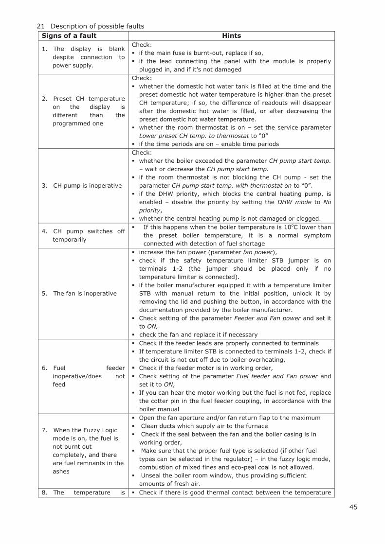
45
21 Description of possible faults
Signs of a fault Hints
1. The display is blank
despite connection to
power supply.
Check:
§ if the main fuse is burnt-out, replace if so,
§ if the lead connecting the panel with the module is properly
plugged in, and if it’s not damaged
2. Preset CH temperature
on the display is
different than the
programmed one
Check:
§ whether the domestic hot water tank is filled at the time and the
preset domestic hot water temperature is higher than the preset
CH temperature; if so, the difference of readouts will disappear
after the domestic hot water is filled, or after decreasing the
preset domestic hot water temperature.
§ whether the room thermostat is on – set the service parameter
Lower preset CH temp. to thermostat to “0”
§ if the time periods are on – enable time periods
3. CH pump is inoperative
Check:
§ whether the boiler exceeded the parameter CH pump start temp.
– wait or decrease the CH pump start temp.
§ if the room thermostat is not blocking the CH pump - set the
parameter CH pump start temp. with thermostat on to “0”.
§ if the DHW priority, which blocks the central heating pump, is
enabled – disable the priority by setting the DHW mode to No
priority,
§ whether the central heating pump is not damaged or clogged.
4. CH pump switches off
temporarily
§ If this happens when the boiler temperature is 10oC lower than
the preset boiler temperature, it is a normal symptom
connected with detection of fuel shortage
5. The fan is inoperative
§ increase the fan power (parameter fan power),
§ check if the safety temperature limiter STB jumper is on
terminals 1-2 (the jumper should be placed only if no
temperature limiter is connected).
§ if the boiler manufacturer equipped it with a temperature limiter
STB with manual return to the initial position, unlock it by
removing the lid and pushing the button, in accordance with the
documentation provided by the boiler manufacturer.
§ Check setting of the parameter Feeder and Fan power and set it
to ON,
§ check the fan and replace it if necessary
6. Fuel feeder
inoperative/does not
feed
§ Check if the feeder leads are properly connected to terminals
§ If temperature limiter STB is connected to terminals 1-2, check if
the circuit is not cut off due to boiler overheating,
§ Check if the feeder motor is in working order,
§ Check setting of the parameter Fuel feeder and Fan power and
set it to ON,
§ If you can hear the motor working but the fuel is not fed, replace
the cotter pin in the fuel feeder coupling, in accordance with the
boiler manual
7. When the Fuzzy Logic
mode is on, the fuel is
not burnt out
completely, and there
are fuel remnants in the
ashes
§ Open the fan aperture and/or fan return flap to the maximum
§ Clean ducts which supply air to the furnace
§ Check if the seal between the fan and the boiler casing is in
working order,
§ Make sure that the proper fuel type is selected (if other fuel
types can be selected in the regulator) – in the fuzzy logic mode,
combustion of mixed fines and eco-peal coal is not allowed.
§ Unseal the boiler room window, thus providing sufficient
amounts of fresh air.
8. The temperature is § Check if there is good thermal contact between the temperature
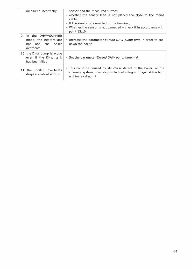
46
measured incorrectly sensor and the measured surface,
§ whether the sensor lead is not placed too close to the mains
cable,
§ If the sensor is connected to the terminal,
§ Whether the sensor is not damaged – check it in accordance with
point 13.10
9. in the DHW=SUMMER
mode, the heaters are
hot and the boiler
overheats
§ Increase the parameter Extend DHW pump time in order to cool
down the boiler
10. the DHW pump is active
even if the DHW tank
has been filled
§ Set the parameter Extend DHW pump time = 0
11. The boiler overheats
despite enabled airflow
§ This could be caused by structural defect of the boiler, or the
chimney system, consisting in lack of safeguard against too high
a chimney draught
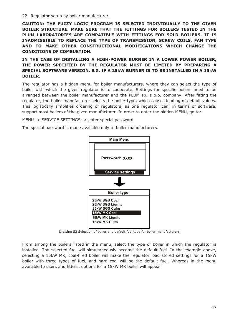
47
22 Regulator setup by boiler manufacturer.
CAUTION: THE FUZZY LOGIC PROGRAM IS SELECTED INDIVIDUALLY TO THE GIVEN
BOILER STRUCTURE. MAKE SURE THAT THE FITTINGS FOR BOILERS TESTED IN THE
PLUM LABORATORIES ARE COMPATIBLE WITH FITTINGS FOR SOLD BOILERS. IT IS
INADMISSIBLE TO REPLACE THE TYPE OF TRANSMISSION, SCREW COILS, FAN TYPE
AND TO MAKE OTHER CONSTRUCTIONAL MODIFICATIONS WHICH CHANGE THE
CONDITIONS OF COMBUSTION.
IN THE CASE OF INSTALLING A HIGH-POWER BURNER IN A LOWER POWER BOILER,
THE POWER SPECIFIED BY THE REGULATOR MUST BE LIMITED BY PREPARING A
SPECIAL SOFTWARE VERSION, E.G. IF A 25kW BURNER IS TO BE INSTALLED IN A 15kW
BOILER.
The regulator has a hidden menu for boiler manufacturers, where they can select the type of
boiler with which the given regulator is to cooperate. Settings for specific boilers need to be
arranged between the boiler manufacturer and the PLUM sp. z o.o. company. After fitting the
regulator, the boiler manufacturer selects the boiler type, which causes loading of default values.
This logistically simplifies ordering of regulators, as one regulator can, in terms of software,
support most boilers of the given manufacturer. In order to enter the hidden MENU, go to:
MENU -> SERVICE SETTINGS -> enter special password.
The special password is made available only to boiler manufacturers.
Drawing 53 Selection of boiler and default fuel type for boiler manufacturers
From among the boilers listed in the menu, select the type of boiler in which the regulator is
installed. The selected fuel will simultaneously become the default fuel. In the example above,
selecting a 15kW MK, coal-fired boiler will make the regulator load stored settings for a 15kW
boiler with three types of fuel, and hard coal will be the default fuel. Whereas in the menu
available to users and fitters, options for a 15kW MK boiler will appear:
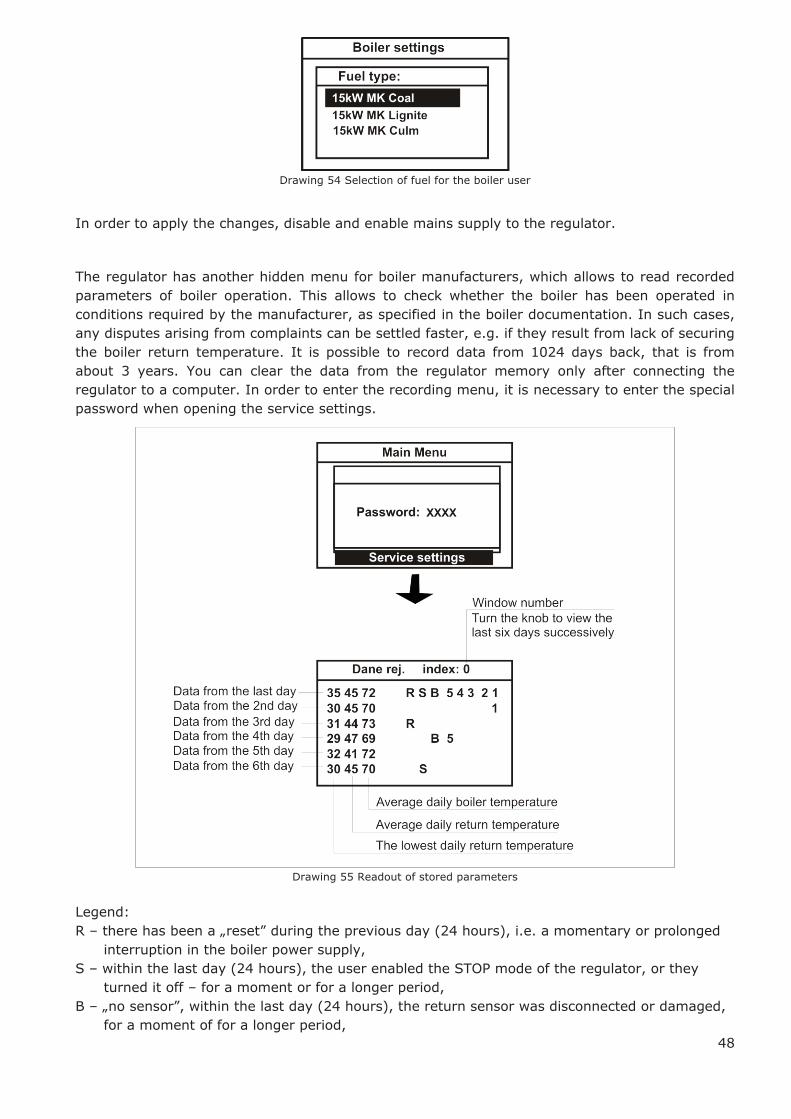
48
Drawing 54 Selection of fuel for the boiler user
In order to apply the changes, disable and enable mains supply to the regulator.
The regulator has another hidden menu for boiler manufacturers, which allows to read recorded
parameters of boiler operation. This allows to check whether the boiler has been operated in
conditions required by the manufacturer, as specified in the boiler documentation. In such cases,
any disputes arising from complaints can be settled faster, e.g. if they result from lack of securing
the boiler return temperature. It is possible to record data from 1024 days back, that is from
about 3 years. You can clear the data from the regulator memory only after connecting the
regulator to a computer. In order to enter the recording menu, it is necessary to enter the special
password when opening the service settings.
Drawing 55 Readout of stored parameters
Legend:
R – there has been a „reset” during the previous day (24 hours), i.e. a momentary or prolonged
interruption in the boiler power supply,
S – within the last day (24 hours), the user enabled the STOP mode of the regulator, or they
turned it off – for a moment or for a longer period,
B – „no sensor”, within the last day (24 hours), the return sensor was disconnected or damaged,
for a moment of for a longer period,
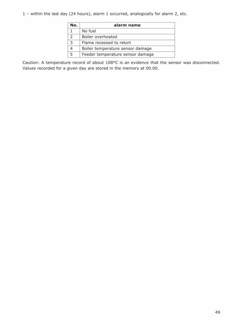
49
1 – within the last day (24 hours), alarm 1 occurred, analogically for alarm 2, etc.
No. alarm name
1 No fuel
2 Boiler overheated
3 Flame recessed to retort
4 Boiler temperature sensor damage
5 Feeder temperature sensor damage
Caution: A temperature record of about 108°C is an evidence that the sensor was disconnected.
Values recorded for a given day are stored in the memory at 00.00.