boron in the primary and secondary coordination spheres of iron
TRANSCRIPT
Boron in the Primary and Secondary Coordination
Spheres of Iron and Nickel
by
Samantha Nicole MacMillan
A.B., Vassar College (2007)
Submitted to the Department of Chemistry
AACHUSETTS INSTI TUTE0F T EC!HNoLoGY
LBPARIES
in partial fulfillment of the requirements for the degree of
Doctor of Philosophy
at the
MASSACHUSETTS INSTITUTE OF TECHNOLOGY
September 2013
@ Massachusetts Institute of Technology 2013. All rights reserved.
Author ......... ...... .. .......Department of Chemistry
July 2, 2013
Certified by . .Jonas C. Peters
Bren Professor of Chemistry, California Institute of TechnologyThesis Supervisor
A ccepted by....... ...... ........................Robert W. Field
Haslam and Dewey Professor of ChemistryChairman, Departmental Committee on Graduate Studies
111

2

This doctoral thesis has been examined by a Committee of the Department of Chemistry as
follows:
. ~ ~ ~ ~ ~ ~ ~ ~ ~ ~ ~ ~ ~ ~ ~ ~ ~ . . .. . ...... .........- -- ------------Stephen J. Lippard
Arthur Amos Noyes Professor of Chemistry
Committee Chairman
Bren Professor of Chemistry, California
Jonas C. PetersInstitute of Technology
Thesis Supervisor
~----- N~
Christopher C. CumminsProfessor of Chemistry
Department of Chemistry
3

4

One thing in my defense, not that it matters: I know something Carter never
knew, or Helene, or maybe you. I know what "nothing" means, and keep on
playing.
Why, BZ would say.
Why not, I say.
- Joan Didion, Play It As It Lays
5

6

For my parents, the most incredible people I know.
7

8

Acknowledgments
I have a confession: acknowledgments make me uncomfortable. I find being privy to
the names, nicknames, inside jokes and other such features of the acknowledgments of
people I know (and some I don't) to be oddly voyeuristic. Writing acknowledgments?
Even worse. The number of people that make any student's time in graduate school more
enjoyable is immense and in my case, having divided my time between MIT and Caltech,
it is staggering. While I would love to mention everyone by name, I simply cannot and
so I will say the following: I have had the pleasure of overlapping with very talented
and intelligent students, staff and faculty at both institutions and have had, with very few
exceptions, positive and rewarding experiences with them all. I have learned a lot from
everyone I have interacted with and have always felt very fortunate to have such a large
support group for both my professional and personal endeavors.
There are, of course, certain people that have had a profound impact and I would like
to mention them individually. First, I would like to thank my thesis advisor, Prof. Jonas
Peters. Jonas gave me a lot of freedom during my graduate career to pursue projects that I
was truly interested in. While many of those projects did not result in publishable papers,
I have learned a lot during my time in the group and appreciate his standing by me while I
explored and eventually lit upon the science that constitutes the bulk of this thesis.
I would also like to thank my thesis committee, Prof. Steve Lippard and Prof. Kit
Cummins, as well as Prof. Dick Schrock and Prof. Dan Nocera, for their insight and
suggestions over the years. Kit has always treated me as one of his own students and I
appreciate his honesty and generosity with his time for all things science. Kit and Dan's
administrative assistant, Allison Kelsey, is phenomenal. She has been a fantastic friend
over the years and always ensures that my visits to Boston are a blast.
In terms of instrumentation, I would like to thank David VanderVelde and Larry Henling
from Caltech for their assistance with NMR and X-ray, respectively. Dave was instrumental
in helping me assess the best experiments to describe the nickel systems featured in Chapter
3. A big, big thank you to Dr. Peter Muller at MIT for his guidance and support about X-
ray crystallography; I am grateful that I was able to interact with and learn from the best in
9

the business.
One of my biggest support systems came in the form of my classmates in the Peters
group: Daniel Suess, Ayumi Takaoka and Charlene Tsay. They have been great friends and
fellow scientists and I am very excited to see what things are in store for them. Dan and
I have been both desk and hood neighbors our entire time in graduate school; it has been
fun and it has certainly been silly. The entire Peters lab has been a good group of people to
work with. I am especially indebted to Hill Harman for being a great desk neighbor, music
recommender and science collaborator. Many thanks to Joe Rheinhardt, who has become
a very good friend and partner in crime. Thank you to Jeff Warren, Ian Tonks, Gretchen
Keller and Oliver Shafaat for being a great group of friends and immediately taking me in
after my arrival at Caltech.
At MIT, I was very close to a small group of people from the Cummins group: Glen
Alliger, Chris Clough, Brandi Cossairt and Jared Silvia. They are an incredible mix of
brains, wit and fun; I had not seen a group of such great thinkers, scientists and friends
before and I am positive that I will be hard pressed to find another group like them. Glen
was an enormous part of my life for a number of years and while circumstances forced us
apart, I still consider him to be one of my best friends and wish him every happiness.
Outside of MIT and Caltech, there are a few very important people to thank. First,
thank you to my undergrad advisor Prof. Joe Tanski, who initially sparked my interest in
chemistry and who continued to be a fantastic mentor even after I left his group. Thank
you to Prof. Rory Waterman for also being a great mentor and for involving me in some
ridiculous hijinks. I also have to thank my future advisor, Prof. Kyle Lancaster, for taking
a chance on me at the San Diego ACS and offering me a position in his labs at Cornell.
An enormous thank you is in order to my best friend Matt Morse, who has never failed at
making me laugh so hard that I cried and who has always taken time from his busy, real-
person schedule to hang out. And finally, my biggest and most important thank you goes
to my parents, Tom and Cindy MacMillan. Their unwavering support and love has kept me
going, even through the toughest spots. I love them both very much and when I grow up, I
want to be just like them.
10

Boron in the Primary and Secondary Coordination Spheres of Iron
and Nickel
by
Samantha Nicole MacMillan
Submitted to the Department of Chemistry on July 2, 2013, in partial fulfillment of therequirements for the degree of Doctor of Philosophy
Abstract
Motivated by the reported electronic versatility of anionic tris(phosphine)borate and tris-(phosphine)silyl ligands, a new, neutral tris(phosphine)borane scaffold was prepared. The
synthesis, spectroscopy and solid-state structures of iron complexes ligated by both ir-acidic and 7r-basic moieties are presented. The cationic imido complex, [[TPBPh]FeNAd]-
[BAr4] ([TPBPh = (2Ph2PC6 H4 )3 B, [BAr~] = tetrakis[3,5-bis(trifluoromethyl)phenyl]bor-ate), was generated and the EPR spectroscopic and solid-state structural features described.This complex is unique among the iron tris(phosphine)borane complexes prepared by thePeters group in that there is no interaction between the iron and boron centers.
The potential for bifunctional catalysis employing the nickel bis(phosphine)borane com-
plex [MesDPBPh]Ni was explored ([MesDPBPh] = (2-Ph 2 PC6 H4 )2 B(1,3,5-Me 3 C 6H2)). Th-
is species activates E-H bonds (E = Si, Ge, S) and traditionally unstable borohydrido-E nickel complexes were isolated. The solid-state structures of these complexes are de-scribed. The catalytic hydrosilylation of para-substituted benzaldehydes was studied and a
mechanism for the transformation proposed. An intermediate nickel borohydridosiloxyal-kyl species was identified and characterized by NMR spectroscopy. A series of nickel boro-hydridothiolate complexes was prepared and a rare, nickel(I) borohydridothiolate specieswas isolated and structurally characterized.
The reactivity of the iron(II) alkyl complex [PhBP h]FeMe towards H2 is presented([PhBP h] = PhB(CH2 PPh2 )j). Exposure of a C6 H6 solution of [PhBpPh]FeMe to an excess
of H2 results in the formation of a previously described iron 17 5 -cyclohexadienyl complex.Repeating the reaction in THF solution with one equivalent of PMe 2Ph yields the dihydro-gen hydride complex [PhBPPh]Fe(H 2)(H)(PMe 2 Ph), as determined by 'H and 31P { H}NMR spectroscopies and a short Ti spin-lattice relaxation measurement. This species is aslow but competent olefin hydrogenation catalyst. In an effort to access a more reactive pre-catalyst, the iron chemistry of the bis(phosphine)borate ligands [Ph2 BPPh] and [Ph2 BPfBu]
([Ph2BP] = Ph2 B(CH2 PR2)3, R = Ph and tBu) was explored. Iron(II) halide, aryloxide,anilido and alkyl complexes were isolated and characterized.
Thesis Supervisor: Jonas C. PetersTitle: Bren Professor of Chemistry, California Institute of Technology
11

12

Contents
Acknowledgments 9
Abstract 11
Table of Contents 13
List of Figures 17
List of Schemes 21
List of Tables 24
List of Abbreviations 27
1 Introduction 31
1.1 M otivation . . . . . . . . . . . . . . . . . . . . . . . . . . . . . . . . . . . 31
1.2 Aspects of Transition-Metal Complexes Featuring Z-Type Ligands . . . . . 35
1.3 Bifunctional Catalysis . . . . . . . . . . . . . . . . . . . . . . . . . . . . . 39
1.4 B ibliography . . . . . . . . . . . . . . . . . . . . . . . . . . . . . . . . . 41
2 Exploring the Lower Limits of An Iron-±Tris(phosphine)borane Interaction 45
2.1 Introduction and Motivation . . . . . . . . . . . . . . . . . . . . . . . . . 46
2.2 Accessing the Iron Chemistry of [TPBPh]. .................. 48
2.3 Chemical Reduction of [TPBPh]FeCl: An Unexpected Product . . . . . . . 52
2.4 Accessing M-L Multiple Bonds: Synthesis of Terminal Imidoiron Com-
plexes . . . . . . . . . . . . . . . . . . . . . . . . . . . . . . . . . . . . . 54
13

2.5
2.6
2.7
2.7.9 Preparation of [[TPBPh]Fe(NAd)] [PF 6]
2.7.10 Preparation of [[TPBPh]Fe(NAd)][BAr
2.7.11 X-ray Crystallographic Details . . . .
2.8 Bibliography . . . . . . . . . . . . . . . . .
M6ssbauer Spectroscopic Studies . . . . . . .
Conclusions and Future Work . . . . . . . . .
Experimental Methods . . . . . . . . . . . .
2.7.1 General Considerations . . . . . . . .
2.7.2 Spectroscopic Measurements .....
2.7.3 Electrochemistry . . . . . . . . . . .
2.7.4 DFT Calculations . . . . . . . . . . .
2.7.5 Preparation of [TPBPh] (2.1).....
2.7.6 Preparation of [TPBPh]FeCl (2.2)
2.7.7 Preparation of [TPBPh']Fe (2.3)
2.7.8 Preparation of [TPBPh]Fe(NAd) (2.4)
73
Bond Activation by a Bifunctional Nickel-Borane System
Introduction and Motivation . . . . . . . . . . . . . . . . . .
Si-H and Ge-H Bond Activation . . . . . . . . . . . . . . .
[MesDPBPh](H)Ni(SiHPh2): Solution Equilibrium Studies . . .
Hydrosilylation of Benzaldehyde by [MesDPBPh]Ni . . . . . .
Probing the Mechanism of Benzaldehyde Hydrosilylation . . .
Conclusions and Future Work . . . . . . . . . . . . . . . . . .
Experimental Methods . . . . . . . . . . . . . . . . . . . . .
3.7.1 General Considerations . . . . . . . . . . . . . . . . .
3.7.2 Spectroscopic Measurements . . . . . . . . . . . . . .
3.7.3 Preparation of [MesDPBPh](H)NiSiH 2Ph (3.2) . . . . .
3.7.4 Preparation of [MesDPBPh](H)NiSiHPh 2 (3.3) . . . . .
3.7.5 Preparation of [MesDPBPh](H)NiGeHPh 2 (3.4) . . . .
3.7.6 Preparation of [MesDPBPh]Ni(fl 2-benzaldehyde) (3.5) .
77
78
80
86
90
92
96
97
97
98
98
99
99
. . . . . . . 100
14
. . . . . . . . . . . . . . . . 6 2
. . . . . . . . . . . . . . . . 6 3
. . . . . . . . . . . . . . . . 64
. . . . . . . . . . . . . . . . 64
. . . . . . . . . . . . . . . . 6 5
. . . . . . . . . . . . . . . . 6 5
. . . . . . . . . . . . . . . . 6 6
. . . . . . . . . . . . . . . . 66
. . . . . . . . . . . . . . . . 67
......... 67
. . . . . . . . . . . . . . . . 6 8
([2.5] [PF6]) . . . . . . . . 68
F] ([2.5][BArF]) . . . . . . . 69
. . . . . . . . . . . . . . . . 6 9
3 Si-H
3.1
3.2
3.3
3.4
3.5
3.6
3.7
3.7.7 General Procedure for Catalytic Hydrosilylation Experiments . . .
3.7.8 General Procedure for Stoichiometric Hydrosilylation Experiments.
3.7.9 Mercury Tests for Homogeneity . . . . . . . . . . . . . . . . . . .
3.7.10 Variable Temperature van't Hoff Study of the Equilibrium of 3.1
and 3.3 . . . . . . . . . . . . . . . . . . . . . . . . . . . . . . . .
3.7.11 Variable Temperature van't Hoff Study of the Equilibrium of 3.1
and [MesDPBPh](D)Ni(SiDPh2) . . . . . . . . . . . . . . . . . .
3.7.12 2D 'H-'H EXSY study of the equilibrium of 3.1 and 3.3 . . . . . .
3.7.13 X-ray Crystallographic Details . . . . . . . . . . . . . .
3.8 Bibliography . . . . . . . . . . . . . . . . . . . . . . . . . . .
4 Isolation of an Unusual Nickel(I) Borohydridothiolate Con
4.1 Introduction . . . . . . . . . . . . . . . . . . . . . . .
Isolation of a Nickel(II) Borohydridothiolate Complex
Substituent Effects on S-H Bond Activation . . . . .
Isolation of a Nickel(I) Borohydridothiolate Complex .
Ni K-Edge XAS Studies . . . . . . . . . . . . . . . .
Conclusions and Future Work . . . . . . . . . . . . . .
Experimental Methods . . . . . . . . . . . . . . . . .
4.7.1 General Considerations . . . . . . . . . . . . .
4.7.2 Spectroscopic Measurements . . . . . . . . . .
4.7.3 Electrochemistry . . . . . . . . . . . . . . . .
4.7.4 X-ray Spectroscopy . . . . . . . . . . . . . . .
4.7.5 DFT Calculations . . . . . . . . . . . . . . . .
4.7.6 Preparation of [MeSDPBPh](H)Ni(SPh) (4.1) . .
. . . . . . 102
. . . . . . 107
plex 113
. . . . . . . . . . . 114
. . . . . . . . . . . 116
. . . . . . . . . . . 118
. . . . . . . . . . . 121
. . . . . . . . . . . 125
. . . . . . . . . . . 126
. . . . . . . . . . . 127
. . . . . . . . . . . 127
. . . . . . . . . . . 128
. . . . . . . . . . . 128
. . . . . . . . . . . 129
. . . . . . . . . . . 129
. . . . . . . . . . . 129
4.7.7 In situ Preparation of a Series of Borohydridothiolate Complexes
(4.2 - 4.6) . . . . . . . . . . . . . . . . . . . . . . . . . . . . . . .
4.7.8 Preparation of [[MeSDPBPh](H)Ni(SPh)][CoCp*] (4.7) . . . . . . .
4.7.9 X-ray Crystallographic Details . . . . . . . . . . . . . . . . . . . .
4.8 Bibliography . . . . . . . . . . . . . . . . . . . . . . . . . . . . . . . . .
15
100
101
101
101
102
102
4.2
4.3
4.4
4.5
4.6
4.7
130
132
132
135

5 Preparation of Low-Valent Iron Complexes Supported by Tris(phos-
phine)borate and Bis(phosphine)borate Ligands 139
5.1 Introduction . . . . . . . . . . . . . . . . . . . . . . . . . . . . . . . . . . 140
5.2 [PhBP h]FeMe: Isolation of an Elusive Species . . . . . . . . . . . . . . . 143
5.3 Hydrogenation Studies Employing [PhBPPh]FeMe . . . . . . . . . . . . . 145
5.4 Accessing the Iron Chemistry of Bis(phosphine)borate Ligands . . . . . . . 151
5.5 Preparation of Bis(phosphine)borate Anilido and Aryloxide Complexes . . 156
5.6 Preparation of Bis(phosphine)borate Alkyl Complexes . . . . . . . . . . . 159
5.7 Pitfalls of the [Ph2 BPR]Fe Systems . . . . . . . . . . . . . . . . . . . . . . 161
5.8 Conclusions and Future Work . . . . . . . . . . . . . . . . . . . . . . . . . 163
5.9 Experimental Methods . . . . . . . . . . . . . . . . . . . . . . . . . . . . 164
5.9.1 General Considerations . . . . . . . . . . . . . . . . . . . . . . . . 164
5.9.2 Spectroscopic Measurements . . . . . . . . . . . . . . . . . . . . . 165
5.9.3 Electrochemistry . . . . . . . . . . . . . . . . . . . . . . . . . . . 165
5.9.4 Magnetic Measurements . . . . . . . . . . . . . . . . . . . . . . . 165
5.9.5 Preparation of [PhBPPh]FeMe (5.1) . . . . . . . . . . . . . . . . . 166
5.9.6 In Situ Generation of [PhBPPh]Fe(PMe 2 Ph)(H)(H 2 ) (5.2) . . . . . . 166
5.9.7 Preparation of [PhBPh]Fe(PMe 2 Ph) (5.3) . . . . . . . . . . . . . . 166
5.9.8 Preparation of [[Ph 2BPPh]FeCl2 ][ASN] (5.4)............ 167
5.9.9 Preparation of {[Ph2 BPu]FeBr}2 (5.5).. . . . . . . . . . . . .. 167
5.9.10 Preparation of [[Ph2 BPth]Fe(NH(Ar)) 2 ][ASN] .6) . . . . . . . .. 167
5.9.11 Preparation of [[Ph 2 BPPh]Fe(Cl)(OAr)][ASN] (5.7) . . . . . . . ..168
5.9.12 Preparation of [[Ph2 BPPh]Fe(O Ar)2 ][ASN] (5.8) . . . . . . . . ..168
5.9.13 Preparation of [[Ph 2BPPh]Fe(Bn) 2 ][ASN] (5.9) . . . . . . . . . ..169
5.9.14 Preparation of [Ph2 BPtu]FeBn (5.10) . . . . . . . . . . . . . . . . 169
5.9.15 X-ray Crystallographic Details . . . . . . . . . . . . . . . . . . . . 170
5.10 Bibliography . . . . . . . . . . . . . . . . . . . . . . . . . . . . . . . . . 173
16

List of Figures
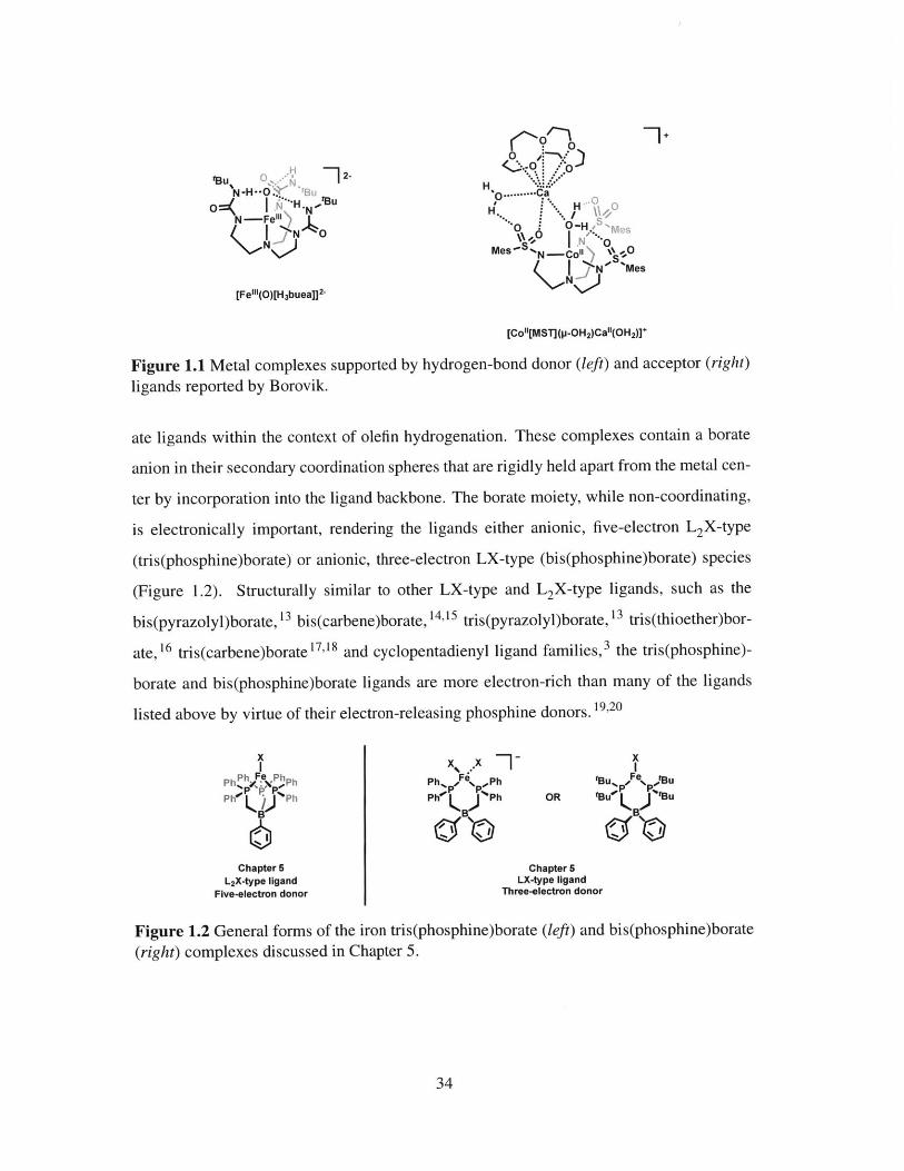
1.1 Metal complexes supported by hydrogen-bond donor (left) and acceptor
(right) ligands reported by Borovik. . . . . . . . . . . . . . . . . . . . . . 34
1.2 General forms of the iron tris(phosphine)borate (left) and bis(phosphine)-
borate (right) complexes discussed in Chapter 5 . . . . . . . . . . . . . . . 34
1.3 (left) Bis(phosphine)borane and tris(phosphine)borane ligands employed in
this dissertation. (right) Molecular orbital representations of metal-ligand
interactions with L-, X- and Z-type ligands. . . . . . . . . . . . . . . . . . 35
1.4 Limiting descriptions of M-B interactions proposed by (left) Parkin and
(right) H ill. . . . . . . . . . . . . . . . . . . . . . . . . . . . . . . . . . . 36
1.5 C3 -symmetric (left) S-donor and (right) P-donor borane ligands. (center)
Plot correlating M-B distance and the pyramidalization of the boron center
for first-row transition metal complexes. . . . . . . . . . . . . . . . . . . . 37
1.6 A family of copper metallaboratranes related by formal redox processes (R
= IP r). . . . . . . . . . . . . . . . . . . . . . . . . . . . . . . . . . . . . . 39
1.7 (left) The nickel bis(phosphine)borane species [MesDPBPh]Ni heterolyti-
cally cleaves H 2 to generate a nickel borohydridohydride species. (right)
Typical and polarity-inverted heterolysis of H2 at a transition metal-ligand
species. . . . . . . . . . . . . . . . . . . . . . . . . . . . . . . . . . . . . 40
2.1 Qualitative d-orbital splitting diagrams for the tris(phosphine)borate scaf-
fold (left) and tris(phosphine)silyl scaffold (right). (center) A hemi-labile
tris(phosphine)borane ligand can access both pseudotetrahedral and trigo-
nal bipyramidal geometries . . . . . . . . . . . . . . . . . . . . . . . . . . 47
17

2.2 Graphical representations of the solid-state structures of [TPBiPr] (left) and
2.1 (right). . . . . . . . . . . . . . . . . . . . . . . . . . . . . . . . . . . . 50
2.3 Solid-state structure of 2.2. . . . . . . . . . . . . . . . . . . . . . . . . . . 51
2.4 Partial 1H NMR spectrum of 2.3 showing the upfield aryl resonances cor-
responding to the rj 6 -coordinated phenyl group. . . . . . . . . . . . . . . . 53
2.5 (left) Solid-state structure of 2.3. (right) Thermal ellipsoid representation
of 2.3 with aryl rings attached to P2 and P3 omitted for clarity. . . . . . . . 54
2.6 Solid-state structure of 2.4. . . . . . . . . . . . . . . . . . . . . . . . . . . 56
2.7 (left) Qualitative d-orbital splitting diagrams illustrating the predicted
ground-state electronic structures of Td and C3, symmetric structures for d6
configurations. (right) Calculated electronic structure of imidoiron 2.4.. . 57
2.8 Surface plots of the orbitals of d 2 (and Fe-B or-bonding) parentage
(HOMO-2), dy parentage (HOMO), and dxz character (LUMO+1) for
im idoiron 2.4. . . . . . . . . . . . . . . . . . . . . . . . . . . . . . . . . . 57
2.9 Cyclic voltammogram of neutral imidoiron complex 2.4. . . . . . . . . . . 58
2.10 Solid-state structure of [2.5][BArF]. . . . . . . . . . . . . . . . . . . . . . 60
2.11 (left) Experimental (black) and simulated (red) X-band EPR spectrum of
[2.5] [PF 6]. (right) Spin density surface calculated for 2.5. . . . . . . . . . 61
2.12 (left) Experimental (black) and simulated (red) X-band EPR spectrum of
[TPBiPr]FeN. (right) SOMO calculated for [TPBiPr]FeN. . . . . . . . . . . 61
2.13 Experimental (black) and simulated (red) M6ssbauer spectra of 2.3, 2.4 and
[2.5] [BA rF]. . . . . . . . . . . . . . . . . . . . . . . . . . . . . . . . . . . 62
3.1 Structurally characterized nickel silyl hydride complexes reported by (left)
Fischer and (right) Radius. . . . . . . . . . . . . . . . . . . . . . . . . . . 79
3.2 Signature resonances in the (a) 1H, (b) 3 1p{ 1H}, (c) 1 1B{'H}, and (d)
29si { 1H} NMR spectra of 3.2. . . . . . . . . . . . . . . . . . . . . . . . . 82
3.3 Solid-state structures of 3.2 (left) and 3.3 (right). . . . . . . . . . . . . . . 84
3.4 Solid-state structure of 3.4. . . . . . . . . . . . . . . . . . . . . . . . . . . 86
18
3.5 Van't Hoff plots derived from variable temperature 1H NMR spectra of the
solution equilibrium of 3.1, 3.3 and free H2SiPh or D2SiPh 2 . . . . . . .. 87
3.6 Representative 1H NMR spectrum of the solution equilibrium of 3.1, 3.3
and free H2SiPh2 . . . . . . . . . . . . . . -. . . . -. -. -. . . . . .. 88
3.7 Representative 'H- 1H EXSY NMR spectrum of the solution equilibrium of
3.1, 3.3 and free H2SiPh2. - - . . . . . . . . . . . . . . . . . . . . . . . . . 89
3.8 Expansion of the 1H-1H EXSY NMR spectrum of the solution equilibrium
of 3.1, 3.3 and free H2SiPh 2. (left) Tm = 0 ms. (right) Tm = 700 ms. . . . . . 89
3.9 Plot of aldehyde concentration versus time for the hydrosilylation of p-
dimethylaminobenzaldehyde by 1.25, 2.5 and 5 mol % of 3.1. . . . . . . . 91
3.10 Hammett correlation diagram for the relative rates of hydrosilylation of
para-substituted benzaldehydes by 3.1 . . . . . . . . . . . . . . . . . . . . 92
3.11 Representative spectra for hydrosilylation under catalytic conditions. (top)
Proton-coupled 13 C NMR spectrum recorded at -60 'C after thawing the
reaction mixture. (middle) Proton-coupled 13C NMR spectrum recorded at
-60 'C after removing from the probe and shaking at room temperature for
5 min. (bottom) 3 1p { 1H} NMR spectrum recorded at room temperature 5
m in after silane addition. . . . . . . . . . . . . . . . . . . . . . . . . . . . 96
4.1 Solid-state structure of 4.1. . . . . . . . . . . . . . . . . . . . . . . . . . . 118
4.2 Comparison of an NHC-supported nickel hydride thiolate complex (left)
and the bis(phosphine)borane complex 4.1 (right). . . . . . . . . . . . . . . 118
4.3 Solid-state structures of 4.4 (left) and 4.6 (right). . . . . . . . . . . . . . . 120
4.4 Examples of square-planar nickel(II) dithiolate/thioether complexes. . . . . 122
4.5 Cyclic voltammogram of neutral nickel borohydridothiolate complex 4.1. . 123
4.6 Solid-state structure of 4.7. . . . . . . . . . . . . . . . . . . . . . . . . . . 124
4.7 (left) Experimental (black) and simulated (red) X-band EPR spectrum of
4.7. (right) Spin density surface calculated for 4.7. . . . . . . . . . . . . . 125
4.8 Normalized Ni K-edge XAS spectra obtained for 4.1 (solid line) and 4.7
(dashed line). The inset shows the edge region between 8325 and 8350 eV. . 126
19
5.1 Iron catalysts reported by (left) Chirik and (right) Peters. . . . . . . . . . . 142
5.2 Solid-state structure of 5.1. . . . . . . . . . . . . . . . . . . . . . . . . . . 145
5.3 Solid-state structure of 5.3. . . . . . . . . . . . . . . . . . . . . . . . . . . 150
5.4 Comparison of metal complexes containing neutral bis(phosphine)silane
(left) and anionic bis(phosphine)borate ligands (right). . . . . . . . . . . . 151
5.5 Comparison of tris(phosphine)borate (left) and anionic bis(phosphine)borate
ligands used in this study (right). . . . . . . . . . . . . . . . . . . . . . . . 152
5.6 SQUID magnetometry data (0.5 T) and fit for 5.4. . . . . . . . . . . . . . . 153
5.7 Solid-state structure of 5.5. . . . . . . . . . . . . . . . . . . . . . . . . . . 154
5.8 (left) Synthesis of [[Ph 2 BPPh]FeCl 2][Tl]. (right) Solid-state structure of
[[Ph2 BPh]FeCl 2 ] . . . . . . . . . . . . . . . . . . . . . . . . . . . . . 155
5.9 Solid-state structure of 5.6. . . . . . . . . . . . . . . . . . . . . . . . . . . 157
5.10 Solid-state structure of 5.7. . . . . . . . . . . . . . . . . . . . . . . . . . . 158
5.11 Solid-state structure of 5.9. . . . . . . . . . . . . . . . . . . . . . . . . . . 160
5.12 Solid-state structure of 5.10. . . . . . . . . . . . . . . . . . . . . . . . . . 161
5.13 Preliminary X-ray analyses suggest that: (left) Treatment of 5.5 with LiN(p-
tol)2 results in dechelation of [Ph2 BP'Bu] and formation of an homoleptic
iron amido species. (right) Reduction of 5.4 results in a mixture of prod-
ucts, one of which is the homoleptic bis(phosphine)borate complex. . . . . 163
20

List of Schemes
1.1 Organosilanes prepared by (top) substitution and (bottom) hydrosilylation. . 32
1.2 Simplified mechanisms for the addition of an E-H substrate to an olefin. . 33
2.1 Both ir-acidic and ic-basic ligands can be accessed by iron complexes sup-
ported by the tris(phosphine)borane ligand, [TPBiPr]. . . . . . . . . . . . . 48
2.2 Synthesis of the tris(phosphine)borane ligand 2.1. . . . . . . . . . . . . . . 49
2.3 Synthesis of the tris(phosphine)borane iron complex 2.2. . . . . . . . . . . 50
2.4 Chemical reduction of 2.2 to generate the reduced iron-arene complex 2.3. 53
2.5 Synthesis of the terminal imidoiron complex 2.4. . . . . . . . . . . . . . . 55
2.6 Chemical oxidation of 2.4 to synthesize the cationic, terminal imidoiron
species [2.5][PF 6 ]. Subsequent anion exchange generates [2.5][BAr ].. . 59
3.1 (left) Chalk-Harrod and modified Chalk-Harrod mechanisms and (right)
Glaser-Tilley mechanism for the hydrosilylation of olefins. . . . . . . . . . 79
3.2 Reversible H2 activation by the bis(phosphine)borane nickel complex 3.1.
Complex 3.1 is also a competent hydrogenation catalyst. . . . . . . . . . . 80
3.3 Synthesis of 3.1 . . . . . . . . . . . . . . . . . . . . . . . . . . . . . . . . 81
3.4 Preparation of the nickel borohydridosilyl complexes 3.2 and 3.3. . . . . . 81
3.5 Treatment of 3.1 with 1 equiv of H2GePh2 yields the borohydridogermyl
com plex 3.4 . . . . . . . . . . . . . . . . . . . . . . . . . . . . . . . . . . 85
3.6 Possible mechanisms for the hydrosilylation of benzaldehyde by 3.1. . . . . 93
3.7 (left) Preparation of 3.5. (right) Solid-state structure of 3.5. . . . . . . . . . 94
3.8 Dehydrogenative silylation of acetophenone catalyzed by 3.1 . . . . . . . . 97
21

4.1 Hydrothiolation pathways for (left) radical or nucleophilic addition and
(right) metal-mediated addition of thiols to alkynes. . . . . . . . . . . . . . 114
4.2 (left) Alkyne insertion into the M-H bond results in the formation of linear
thioether products. (right) Insertion into the M-S bond forms branched
Markovnikov vinyl sulfide compounds. . . . . . . . . . . . . . . . . . . . 115
4.3 Treatment of 3.1 with 1 equiv HSPh yields the green borohydridothiolate
com plex 4.1 . . . . . . . . . . . . . . . . . . . . . . . . . . . . . . . . . . 117
4.4 Preparation of para-substituted thiolate complexes 4.2 - 4.6. . . . . . . . . 119
4.5 Preparation of the anionic nickel(I) borohydridothiolate complex 4.7. . . . . 123
5.1 Hydrogenolysis of [PhBPh]Fe-NAr. The purported iron(II) benzene adduct
is not experimentally observed. . . . . . . . . . . . . . . . . . . . . . . . . 143
5.2 (left) Treatment of [PhBpPh]FeCl with alkyllithium and Grignard reagents
leads to overreduction of the metal center. (right) Overreduction can be
avoided using M e2M g. . . . . . . . . . . . . . . . . . . . . . . . . . . . . 144
5.3 Catalytic hydrogenation of 1-hexene by 10 mol % of 5.1. . . . . . . . . . . 146
5.4 Hydrogenolysis of 5.1 in C6 H6 forms the stable, i 5 -cyclohexadienyl com-
plex (left), while in THF results in a bright green solution. This solution
is proposed to contain an Fe-H unit on the basis of subsequent reactivity
with CO (right) and C6 H6 (bottom). . . . . . . . . . . . . . . . . . . . . . 147
5.5 Hydrogenation of a THF solution of 5.1 in the presence of PMe 2 Ph yields
the orange dihydrogen hydride species 5.2 . . . . . . . . . . . . . . . . . . 149
5.6 Independent synthesis of 5.3 by reduction of [PhBPh]FeCl with Na/Hg in
the presence of excess PMe 2 Ph. . . . . . . . . . . . . . . . . . . . . . . . 150
5.7 Treatment of [Ph2 BPPh] [ASN] with FeCl2 yields the 'ate' complex 5.4. 153
5.8 Treatment of [Ph2 BPtBu][Tl] with FeBr2 yields the dimeric (y -Br) 2 com-
plex 5.5. . . . . . . . . . . . . . . . . . . . . . . . . . . . . . . . . . . . . 154
5.9 Treatment of 5.4 with LiNHAr (Ar = 2,6-diisopropylphenyl) yields the
bis(anilido) complex 5.6. . . . . . . . . . . . . . . . . . . . . . . . . . . . 157
22
5.10 Treatment of 5.4 with 1 or 2 equiv of TlOAr (Ar = 2,6-diisopropylphenyl)
yields the mono and bis(aryloxide) complexes 5.7 (left) and 5.8 (right),
respectively. . . . . . . . . . . . . . . . . . . . . . . . . . . . . . . . . . . 158
5.11 Treatment of 5.4 with 2 equiv of BnMgCl yields the bis(benzyl) complex 5.9.159
5.12 Treatment of 5.5 with 2 equiv of BnMgCl yields the benzyl complex 5.10. . 161
23

24

List of Tables
2.1 Comparison of selected bond lengths and angles of 2.2 and [TPBiPr]FeBr. 52
2.2 Mulliken spin densities calculated for 2.5. . . . . . . . . . . . . . . . . . . 66
2.3 Crystallographic summary for 2.2 and 2.3. . . . . . . . . . . . . . . . . . . 71
2.4 Crystallographic summary for 2.4 and [2.5] [BAr4].............. 72
3.1 Comparison of the signature NMR resonances of 3.2 and 3.3. . . . . . . . . 83
3.2 Selected bond lengths (A) and angles (0) for 3.2 and 3.3. . . . . . . . . . . 85
3.3 Rate constants for the solution equilibrium of 3.1, 3.3 and free H2 SiPh 2
as determined by 2D EXSY spectroscopy. Keq values determined by the
variable temperature van't Hoff analysis are included for comparison. . . . 90
3.4 Summary of results of catalytic hydrosilylation of para-substituted ben-
zaldehydes by 3.1 . . . . . . . . . . . . . . . . . . . . . . . . . . . . . . . 91
3.5 Crystallographic summary for 3.2, 3.3 and 3.5. . . . . . . . . . . . . . . . 104
3.6 Crystallographic summary for 3.4 and 3.5. . . . . . . . . . . . . . . . . . . 105
4.1 Comparison of the signature NMR resonances of borohydridothiolate com-
plexes. . . . . . . . . . . . . . . . . . . . . . . . . . . . . . . . . . . . . . 119
4.2 Comparison of selected bond lengths (A) and angles (0) for 4.6, 4.1 and 4.4. 120
4.3 Maximum absorption wavelengths in the UV-vis spectra of the nickel boro-
hydrido-thiolate complexes in C6 H6 4.1 - 4.6. . . . . . . . . . . . . . . . . 121
4.4 Mulliken spin densities calculated for 4.7. . . . . . . . . . . . . . . . . . . 129
4.5 Crystallographic summary for 4.1 and 4.4. . . . . . . . . . . . . . . . . . . 133
4.6 Crystallographic summary for 4.6 and 4.7. . . . . . . . . . . . . . . . . . . 134
25

5.1 Comparison of Fe-C distances of structurally characterized L 3Fe alkyl
species. . . . . . . . . . . . . . . . . . . . . . . . . . . . . . . . . . . . . 145
5.2 Crystallographic summary for 5.1 and 5.3. . . . . . . . . . . . . . . . . . . 171
5.3 Crystallographic summary for 5.7, 5.9 and 5.10. . . . . . . . . . . . . . . . 172
26

List of Abbreviations
a ............. ............a . . . . . . . . . . . . . . . . . . . . . . . . .
A ...............A d ..... ...................anal .... ..................A r . .. ....................atm .... ...................
A SN .... ...................3 . . . . . . . . . . . . . . . . . . . . . .
b . . . . . . . . . . . . . . . . . . . . . . . . .B n .... ....................b r ............ ............
B u ........................C .... ....................C .........................
C .........................C . .. ....................
1c . ... ..... . . ........ .....
cal ........................
calcd .... ..................
C C D ......................cod ... ...................cod . . ...... .. . .... ........ .C p ..... ..... ............C p .......................
A . . . . . . . . . . . . . . . . . . . . . . . . .
d . . . .. . . . . . . . . . . . . . . . . . . . .
angle a
axis a
angstrom
adamantyl
analysis (Anal. in combustion analysis presentations)
aryl
atmosphere
5-azoniaspiro[4.4]nonane
angle#
axis b
benzyl
broad or broadened
butyl
Celcius
axis c
symmetry group
carbon nuclear magnetic resonance
circa, about
calorie
calculated
charge-coupled device
1,5-cyclooctadiene
cyclopentadienyl
pentamethylcyclopentadienyl
NMR chemical shift in parts per million
change
day, deuteron, doublet (spectra)
27
........... two-dimensionaldegDFT
E..E".
EI/2
e.g.ed.E d . ...............E ds. ..............ENDOR ..........EPR ..............equiv .............E SR ..............E t ................
eu ................EXSY ............F .................19F ...............
F c ................FLP ..............fw ................
Y .................G .................G . ...............G .................G C ...............G H z ..............G oF ..............h .................h ................H .................
1H .. .. .. .. . ... . . ..
hk1 . ... . ... .. .. .. . .HOMO ...........HSQC ............i.e ................i ..................IR .......................J ........................
...........................................
......................
......................
....................... . . . . . . . . ..- - . . . . . . . . . .
......................
......................
28
2D .....
. degree (0)
. density functional theory
. molar absorptivity. energy. standard electrode potential. half-wave potential
. for example. edition, edited. editor. editors. electron-nuclear double resonance. electron paramagnetic resonance. equivalent. electron spin resonance. ethyl. entropy unit. exchange spectroscopy. crystallographic structure factor. fluorine nuclear magnetic resonance. ferrocene. frustrated Lewis pair. formula weight. angle y. gram. splitting factor (ESR and NMR spectroscopy)
gauss, giga (109). gas chromatography. gigahertz. goodness of fit. hour. crystallographic index (hkl). enthalpy. proton nuclear magnetic resonance. crystallographic index. highest occupied molecular orbital. heteronuclear single quantum coherence spectroscopy. that is. iso (as in 'Pr). infrared
. coupling constant (NMR and ESR spectroscopy)
k ........................k ........................K .........................K . ........................X . . . . . . . . . . . . . . . . . . . . . . . . .
Amax ......................
1 . . . . . . . . . . . . . . . . . . . . . . . . . .
L . . . . . . . . . . . . . . . . . . .. . . . . .L A H ......................LM CT ...................LU M O ....................
U . . . . . . . . . . . . . . . . . . . . . . . . .
AB - -........................
meff ......................m .........................
M ........................M e .......................M es ......................M H z ......................m in .......................M O .......................m ol .......................m ol% ....................n . . . . . . . . . . . . . . . . . . . . . . . . .n . . . . . . . . . . . . . . . . . . . . . . . . .
naph ......................nm .......................N M R .. ... . ... .. .. .. .. .. . .
0 . ............. :...........
ob sd ......................O E C ......................% ........................
X . . . . . . . . . . . . . . . . . . . . . . . . .
P . . . . . . . . . . . . . . . .. . . . . . . . .31P .......................
P h ........................
ppm ......................P r ........................
P S II ......................
q . . . . . . . . . . . . . . . . . . . . . . . . .R .. . . . . . . . . . . . . . . . . . . . . . . .
kilo (103)
crystallographic index (hkl), rate constant
kelvin
equilibrium constant
wavelength
wavelength of maximum absorption
crystallographic index (hkl)
ligand, liter
lithium aluminum hydride
ligand-to-metal charge transfer
lowest unoccupied molecular orbital
micro (10-6)Bohr magneton
effective magnetic moment
meter, milli (10-3), multiplet (spectra)
metal, molar (mol L- 1), mega (106)methyl
mesityl (2,4,6-trimethylphenyl)
megahertz
minute
molecular orbital
mole
mole percent
nano (10-9)
normal (as in "Bu)
napthalenide
nanometer
nuclear magnetic resonance
ortho
observed
oxygen evolving complex
percent
type of orbital, electron
para
phosphorus nuclear magnetic resonance
phenyl
parts per million
propylphotosystem II
quartet (spectra)
generic organic group, residual value (crystallography)
29

ref ........................0.........................E.........................
s .........................
S .........................29s .. . . . . . . . . . .
5i.......... .............
SOF .......SOMO .....t . . . . . . . . . . .
t . . . . . . . . . . .
t1/2 .. . . . . . .
T ..........T ..........205TI . .. .. . .
THF .......tol .........
T s .........
UV ........UV-vis .....V . . . . . . . . . . . . . . . . . . . . . . . . .
V .......... ...............v is ........................
v s ........................
w R .......................
w t ........................
X .........................X A S .....................z .........................
reference
type of orbital, electronsummationsecond, singlet (spectra)entropy, electronic spinsilicon nuclear magnetic resonancesite occupancy factor
singly occupied molecular orbital
triplettertiary (as in 'Bu), timehalf-lifetesla
temperature (in kelvins)thallium nuclear magnetic resonancetetrahydrofuran
tolyl (4-methylphenyl)tosyl (4-toluenesulfonyl)ultravioletultraviolet-visiblescan rateunit cell volume, voltvisibleversus
weighted R-factor
weightgeneric anionic ligandX-ray absorption spectroscopynumber of molecules in unit cell
30

1 Introduction
Contents
1.1 Motivation . . . . . . . . . . . . . . . . . . . . . . . . . . . . . . . . 31
1.2 Aspects of Transition-Metal Complexes Featuring Z-Type Ligands 35
1.3 Bifunctional Catalysis .. . . . . . . . . . . . . . . . . . . . . . . . . 39
1.4 Bibliography . . . . ... . . . . .. . . . . . . . . . . . . . . . . . . 41
1.1 Motivation
A persistent challenge facing organometallic chemists is the development of new chemical
transformations that employ abundant and inexpensive reagents (N 2 , H2 , C0 2, CO, olefins,
etc.) for the preparation of value-added chemical products.1 One attractive approach to
the functionalization of such small molecules is the activation of an E-H bond (E = main
group element) by a transition-metal complex, followed by group transfer to the unsat-
urated substrate of interest. Based on an E-H addition process rather than substitution,
these reactions provide an atom economic route for the construction of new a-bonds, as
demonstrated in Scheme 1.1. The development of catalytic methods that use E-H sub-
strates to break and forge a-bonds is therefore an important goal to address.
The reactivity patterns of organometallic complexes are intimately associated with the
identities of the transition-metal centers and the number and type of ligands bound di-
rectly to the metal centers.2,3 To illustrate these principles, two simplified mechanistic
pathways for the metal-mediated addition of an E-H substrate to an olefin are outlined
31

Preparation by substitution:
1. Hydroboration R' Br Mg R CISiR3 NR . riaion A iR B ---- MgBr -* R SiR3
Preparation by E-H bond addition:
cat.R SiR 3
Scheme 1.1 Organosilanes prepared by (top) nucleophilic displacement of halogen from ahalosilane by the appropriate organometallic reagent (i.e., substitution) and (bottom) addi-tion of silane to the alkene double bond (i.e., hydrosilylation).
in Scheme 1.2. For an electron-rich transition-metal complex, the catalytic cycle often in-
volves oxidative addition of the E-H bond, coordination of the olefin, insertion into either
the M-E or M-H bond, and reductive elimination of the product molecule (Scheme 1.2,
left).4'5 In such a cycle, both the oxidation state and the coordination number of the metal
center are increased by two upon oxidative addition of the E-H bond. This step is typi-
cally promoted by coordinatively unsaturated complexes ligated by strong a--donors, such
as alkylphosphine and N-heterocyclic carbene (NHC) ligands. Rational modification of
the steric profile of these ancillary ligands can help facilitate reductive elimination of the
product and regeneration of the starting metal complex. 6,7 For an electrophilic metal cen-
ter, the catalytic cycle may consist of olefin coordination, nucleophilic attack by the E-H
substrate and then protonolysis to release the product molecule (Scheme 1.2, right).8 '9 For
this pathway, a more Lewis acidic metal center will render the coordinated olefin more
electrophilic and thereby more susceptible to nucleophilic attack by the E-H substrate.
Both mechanistic pathways can be significantly impacted by changes in the surrounding
ligands; thus, the development of new ligand scaffolds that are able to fine tune the steric
and electronic properties of an organometallic complex, particularly with respect to pro-
moting novel reactivity, constitutes a large and ongoing area of research in the inorganic
community.
32

XLE E-H MXL,
E
L, M +2 -
H E ~MxLn XL
H E-H E-HMXLL
Favored by:Nucleophilic metal centers Favored by:
Strong (i-donor ancillary ligands (e.g., phosphine, NHC) Electrophilic/Lewis-acidic metal centersStrong backdonation (M -+ o*) Strong a-donation (M*- olefln)
Scheme 1.2 Simplified mechanisms for the addition of an E-H substrate to an olefin.Electron-rich metal centers typically follow an oxidative addition pathway (left), whileelectrophilic metal centers promote nucleophilic attack of the olefin by the E-H substrate(right).
In addition to the parameters discussed above, the interaction of a metal center or in-
coming substrate with the secondary coordination sphere can also play a role in the reactiv-
ity of the complex. An elegant example of this concept is the work of Borovik in which both
hydrogen-bond donor and acceptor ligand scaffolds have been explored to stabilize several
unusual species (Figure 1.1). For example, a high-spin, trigonal bipyramidal iron(III) oxo
complex has been isolated using the trianionic ligand [H 3 buea] 3- ([H 3 buea] 3- = tris[(N'-
tertbutylureaylato)-N-ethyl]aminato, Figure 1.1, left). 10,11 The solid-state structure of this
complex shows that the three urea NH groups are directed toward the oxo oxygen atom,
suggesting the presence of intramolecular hydrogen bonding. The x0- -.Nurea distances
observed in the structure (2.69 - 2.73 A), as well as solid-state IR spectroscopic measure-
ments (V(N-H) = 3130 cm') and DFT calculations, support the formulation of the species
as an iron(III) oxo complex surrounded by a hydrogen bonding cavity. Employing the
hydrogen-bond acceptor ligand [MST]'- ([MST]3 - = N,N',N"-[2,2',2"-nitrilotris(ethane-
2,1-diyl)]tris-(2,4,6-trimethylbenzenesulfonamido)), a cobalt(II)-(P-0H2)-calcium(II) bi-
metallic complex can be generated (Figure 1.1, right). 12 In this complex, the aquo lig-
and forms two intramolecular hydrogen bonds to two of the three sulfonamido groups of
[MST] 3-, as determined by X-ray crystallographic analysis.
Chapter 5 describes the iron chemistry of tris(phosphine)borate and bis(phosphine)bor-
3-3
tBU C. _72-
N -H H- . 3U
1N--F4 0N
[Fe'"(O)[H3buea]] 2-
0 CH. +
0 ..........CH'.. H 0
0O O-H.,e
Mes; I N*
_N NMesN I--
[Co"[MST](p-OH 2)Ca"(OH 2)]*
Figure 1.1 Metal complexes supported by hydrogen-bond donor (left) and acceptor (right)
ligands reported by Borovik.
ate ligands within the context of olefin hydrogenation. These complexes contain a borate
anion in their secondary coordination spheres that are rigidly held apart from the metal cen-
ter by incorporation into the ligand backbone. The borate moiety, while non-coordinating,
is electronically important, rendering the ligands either anionic, five-electron L2X-type
(tris(phosphine)borate) or anionic, three-electron LX-type (bis(phosphine)borate) species
(Figure 1.2). Structurally similar to other LX-type and L2X-type ligands, such as the
bis(pyrazolyl)borate,1 3 bis(carbene)borate, 14,15 tris(pyrazolyl)borate,1 3 tris(thioether)bor-
ate, 16 tris(carbene)borate 17 18 and cyclopentadienyl ligand families, 3 the tris(phosphine)-
borate and bis(phosphine)borate ligands are more electron-rich than many of the ligands
listed above by virtue of their electron-releasing phosphine donors. 19,20
xPh Fe hPh
Phr **Ph
B
Chapter 5L2X-type ligand
Five-electron donor
Ph% *Fe Ph
Phie )JPh
B____)
xtuFe,, tMu
OR tUo 3tBuLIB U
Chapter 5LX-type ligand
Three-electron donor
Figure 1.2 General forms of the iron tris(phosphine)borate (left) and bis(phosphine)borate
(right) complexes discussed in Chapter 5.
34

1.2 Aspects of Transition-Metal Complexes Featuring Z-
Type Ligands
The role of metal-borane interactions and their ability to mediate E-H bond activation
processes are central to this dissertation. Described in Chapters 2, 3 and 4 are complexes
of neutral tris(phosphine)borane and bis(phosphine)borane ligands (Figure 1.3, left). 21 24
These ligands feature two or three 7c-accepting phosphine ligands and a a-accepting bo-
rane ligand. In contrast to the well-known L-type (two-electron donor) and X-type (one-
electron donor) ligands, the coordination chemistry of such Z-type (zero-electron donor)
ligands is far less developed (Figure 1.3, right). Following Hill's report of a Ru-B bond
in [B(mimM e)3]Ru(CO)(PPh 3) (mmMe = 2-mercapto-1-methylimidazolyl), the number
and type of transition-metal borane complexes has increased dramatically, including those
of mid to late first-row transition metals. 24,26- 38
M 4-L M-X M -- Z
Ph 2P PPh2-
Chapter2 L M
Ph 2P Mes PPh 2
L-type ligand X-type ligand Z-type ligandTwo-electron donor One-electron donor Zero-electron donor
e.g., PPh 3, CO e.g., Cl, CH 3, H e.g., BH 3, AIPh3Chapters 3 and 4 (Dative covalent bond) (Two-electron covalent bond) (Dative covalent bond)
Figure 1.3 (left) Bis(phosphine)borane and tris(phosphine)borane ligands employed in thisdissertation. (right) Molecular orbital representations of metal-ligand interactions with L-,X- and Z-type ligands. 39
M-BR3 interactions are straightforward. When bound to a transition metal, the oth-
erwise trigonal borane boron atom is pyramidalized to some extent. Because free boranes
have no lone pairs, the electrons in the M-B bond originate exclusively from the metal
center, resulting in a a-acceptor interaction. However, the formalisms associated with as-
signment of the d-electron count and metal oxidation state can complicate the description of
such interactions. Parkin 40 and Hill 41 have proposed two bonding scenarios for complexes
35
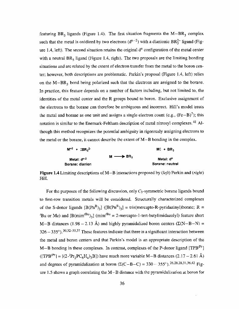
featuring BR 3 ligands (Figure 1.4). The first situation fragments the M-BR3 complex
such that the metal is oxidized by two electrons (d- 2) with a dianionic BR2- ligand (Fig-
ure 1.4, left). The second situation retains the original d" configuration of the metal center
with a neutral BR 3 ligand (Figure 1.4, right). The two proposals are the limiting bonding
situations and are related by the extent of electron transfer from the metal to the boron cen-
ter; however, both descriptions are problematic. Parkin's proposal (Figure 1.4, left) relies
on the M-BR3 bond being polarized such that the electrons are assigned to the borane.
In practice, this feature depends on a number of factors including, but not limited to, the
identities of the metal center and the R groups bound to boron. Exclusive assignment of
the electrons to the borane can therefore be ambiguous and incorrect. Hill's model treats
the metal and borane as one unit and assigns a single electron count (e.g., (Fe-B)7 ); this
notation is similar to the Enemark-Feltham description of metal nitrosyl complexes.41 Al-
though this method recognizes the potential ambiguity in rigorously assigning electrons to
the metal or the borane, it cannot describe the extent of M-B bonding in the complex.
M+2 + :BR 32- M: + BR 3
Metal: dn-2 M -- BR3 Metal: d"Borane: dianion Borane: neutral
Figure 1.4 Limiting descriptions of M-B interactions proposed by (left) Parkin and (right)
Hill.
For the purposes of the following discussion, only C3 -symmetric borane ligands bound
to first-row transition metals will be considered. Structurally characterized complexes
of the S-donor ligands [B(PnR) 3] ([B(PnR) 3] = tris(mercapto-R-pyridazinyl)borate; R =
tBu or Me) and [B(mimtBu) 3] (mimtBu = 2-mercapto-1-tert-butylimidazolyl) feature short
M-B distances (1.98 - 2.13 A) and highly pyramidalized boron centers (E(N-B-N) =
326 - 3350).30,32-35,37 These features indicate that there is a significant interaction between
the metal and boron centers and that Parkin's model is an appropriate description of the
M-B bonding in these complexes. In contrast, complexes of the P-donor ligand [TPBiPr]
([TPBiPr] = [(2 -'Pr2PC 6H4)3B]) have much more variable M-B distances (2.17 - 2.61 A)
and degrees of pyramidalization at boron (E(C-B-C) = 330 - 3550).26,28,28,31,36,42 Fig-
ure 1.5 shows a graph correlating the M-B distance with the pyramidalization at boron for
36

structurally characterized first-row transition-metal complexes ligated by S- and P-donor
borane ligands (center). This plot highlights an important aspect of the [TPB"r] ligand: the
M-B interaction is highly flexible and can adjust according to the electronic requirements
of the metal center (e.g., overall charge, identity of the metal, identity of the ancillary lig-
ands, etc). Given the variability of the M-B interaction and, as a consequence, the extent
of the electron donation from the metal to the boron center and the covalency of this inter-
action, it is clear that the concept of oxidation states is ill-equipped to describe the bonding
in complexes ligated by [TPB'].
0 S-donor LigandsN A P-donor Ligands
350A BN R AA
R i ii345[B(PnR)a] AA A 'Pr 2 r2
S340 ArA A A A
'B N335 A[PB'o A
,Bu 325 0
S 2 2.2 2.4 2.6
[B(mImfBU) 3] M-B Distance (A)
Figure 1.5 C3-symmetric (left) S-donor and (right) P-donor borane ligands. (center) Plotcorrelating M-B distance and the pyramidalization of the boron center for first-row transi-tion metal complexes. 43
In the future, boron K-edge XAS could prove to be a powerful probe of the strength of
a M-B interaction, however it is not yet a routine or widely accessible technique due to
the technical difficulties associated with low-energy data collection. To assess the extent
of a M-B interaction, there are only a few techniques in the synthetic chemists' toolbox.
For diamagnetic complexes, the 11B { H} NMR shift is a convenient and reliable measure
of the electron density at boron, with more upfield shifted resonances corresponding to an
increase in electron density and the formation of an adduct.44,4 5 For S = 1/2 species, EPR is
a valuable technique; in order to determine the amount of boron character in the M-B unit,
the unpaired spin must reside in the M-B orbital such that the hyperfine coupling to boron
can be resolved. Chapter 2 explores the iron chemistry of an aryl-substituted [TPB] ligand
37

in an effort to modify the donor-acceptor relationship between the iron and boron centers
and probe the lower limits of their interaction. A number of paramagnetic complexes are
described for which information about the M-B interaction cannot be readily acquired
via NMR or EPR spectroscopy. Thus, we rely on X-ray crystallography, which is the most
general method for evaluating the M-B interactions of both diamagnetic and paramagnetic
species, albeit with some limitations (vide infra).
Strong M-B bonding should result in a number of physical observables: an upfield
shifted 11B {1 H} NMR spectrum (for a diamagnetic species), a short M-B distance and
a pyramidalized boron center. The structural parameters for the [TPBiPr] complexes il-
lustrated in Figure 1.5 (center) indicate weaker M-B interactions in comparison to those
of S-donor borane ligands. The correlation of the metrical parameters obtained by X-ray
crystallographic analyses can be ambiguous if the distance or pyramidalization are inter-
mediate in value (i.e., a long M-B distance coupled with a highly pyramidalized boron
center or a short M-B distance coupled with a nearly planar boron center, vide supra). An
example of the flexibility of the M-B interaction and correlation with the pyramidalization
of boron as a function of the Lewis basicity of the metal center is shown in Figure 1.6.36
As expected, the Cu-B distance of [TPBiPr]Cu decreases upon reduction to the anionic
complex [[TPBiPr]Cu][Na] (2.289 A vs 2.198 A). Oxidation of [TPBiPr]Cu to the cationic
species [[TPBiPr]Cu][BAr ] results in an increase of the Cu-B distance from 2.289 Ato 2.495 A. The pyramidalization at boron decreases with each one-electron oxidation,
resulting in a nearly planar boron center in the cationic species. This lack of pyramidal-
ization indicates that there is little to no Cu-B interaction. Of the reported structurally
characterized [TPBiPr] complexes, the imidoiron species [TPBiPr]FeN(p-(OMe)C 6H4) has
the longest M-B distance at 2.608 A.28 Based on the copper series discussed above, one
would assume that long M-B distances equate to near-zero interaction and that there is
no interaction between the iron and boron centers of the imidoiron complex. However,
the pyramidalization at boron is significant (338'), indicating that there is some degree of
Fe-B interaction, despite the long distance. This ambiguity will arise again in Chapter
2. In addition, the preparation of a [TPB]Fe complex in which the Fe-B interaction is
unequivocally absent will be presented.
38

R2 P-,Cu- R2 + R2P-Cu- R2 R2P'%*Cu- R27
B BB
Cu-B = 2.495 A Cu-B = 2.289 A Cu-B = 2.198 A2(C-B-C) = 355.0* J(C-B-C) = 347.10 X(C-B-C) = 338.90
Figure 1.6 A family of copper metallaboratranes related by formal redox processes (R =iPr).
1.3 Bifunctional Catalysis
The Lewis acidic functionality of Z-type borane ligands can accommodate lower transition-
metal oxidation states by direct interaction with the metal center; in principle, the bo-
rane can also operate in tandem with the metal center to activate small-molecule sub-
strates 24,30,33,46-50 As an extension this bifunctional concept, the interaction of a transition-
metal center with a Lewis acidic borane can be considered a minimal heterobimetallic
system in which the borane mimics a second metal center. These complexes have a dis-
tinct advantage over traditional heterobimetallic species in that the second "metal" is pre-
installed in the ligand framework. 48 This strategy could help circumvent the deleterious
one-electron processes typically associated with first-row transition-metal complexes in fa-
vor of concerted two-electron transformations such as those observed for hydrogenation
and hydrosilylation processes.
The Peters group recently reported the reversible H2 addition across a nickel bis(phos-
phine)borane species, as shown in Figure 1.7 (left).24 Heterolysis of H2 by [MesDPBPh]Ni
results in the nickel borohydridohydride species [MesDPBPh](H)Ni(H) (MesDPBPh = (2-
Ph2PC6H4)2B(l,3,5-Me 3C6H2). This reaction is conceptually related to H2 activation by
frustrated Lewis pairs (FLPs). 51 However, the polarity of this transformation is inverted
relative to typical H2 heterolysis reactions, in which the metal center acts as the Lewis acid
and accepts H~ while an internal or exogeneous base accepts H'. 52 For [MesDPBPh]Ni,
the nickel center acts as the Lewis acid and accepts H' and the Lewis acidic borane ac-
cepts H- (Figure 1.7, right). The few reported examples of transition metal/FLP systems
also display this reactivity. 53,54 An important feature of the [MsDPBPh]Ni system is that
39

the activated metal hydride/borohydride pair can be intercepted by olefins to achieve cat-
alytic olefin hydrogenation. Inspired by these results, Chapters 3 and 4 explore Si-H and
S-H bond activation by [MesDPBPh]Ni, in an effort to effect catalytic functionalization
of small molecules, a major goal set out at the beginning of this introduction. Chapter 3
describes the catalytic hydrosilylation of substituted benzaldehydes and outlines a mecha-
nistic proposal for this transformation based on detailed NMR experiments. In Chapter 4,
the S-H bond activation of substituted thiophenols is discussed. While catalytic processes
incorporating this bond activation process have not yet been realized with [MesDPBPh]Ni,
a rare nickel(I) borohydridothiolate complex has been isolated and its solid-state structure
is described. Taken together, Chapters 3 and 4 demonstrate not only the capacity of the
[MesDPBPh] ligand scaffold to stabilize unusual and reactive species, but also its flexibil-
ity and ability to support first-row transition-metal catalysts that can mediate productive
two-electron processes typically carried out by noble-metal catalysts.
P- 6+2 B Ni-H H H-H
!7- H2 I (. \Ph2 Ph.,
Figure 1.7 (left) The nickel bis(phosphine)borane species [MesDPBPh]Ni heterolyticallycleaves H2 to generate the nickel borohydridohydride species [MesDPBPh](H)Ni(H). (right)Typical and polarity-inverted heterolysis of H2 at a transition metal-ligand species.
40

1.4 Bibliography
[1] Tolman, W. B. Activation of Small Molecules; Wiley-VCH: Weinheim, Germany,2006.
[2] Hartwig, J. F. Organotransition Metal Chemistry: From Bonding to Catalysis; Uni-versity Science Books: Sausalito, CA, 2010.
[3] Crabtree, R. H. The Organometallic Chemistry of the Transition Metals; John Wiley& Sons: New York, 2001.
[4] Colby, D. A.; Bergman, R. G.; Ellman, J. A. Chem. Rev. 2010, 110, 624-655.
[5] Chalk, A. J.; Harrod, J. F. J. Am. Chem. Soc. 1965, 87, 16-21.
[6] Furuya, T.; Benitez, D.; Tkatchouk, E.; Strom, A. E.; Tang, P.; Goddard, W. A., III;Ritter, T. J. Am. Chem. Soc. 2010, 132, 3793-3807.
[7] Culkin, D. A.; Hartwig, J. F. Organometallics 2004, 23, 3398-3416.
[8] Johns, A. M.; Utsunomiya, M.; Incarvito, C. D.; Hartwig, J. F. J. Am. Chem. Soc.2006, 128, 1828-1839.
[9] Takaya, J.; Hartwig, J. F. J. Am. Chem. Soc. 2005, 127, 5756-5757.
[10] Borovik, A. S. Acc. Chem. Res. 2005, 38, 54-61.
[11] MacBeth, C. E.; Golombek, A. P.; Young, V. G., Jr; Yang, C.; Kuczera, K.; Hen-drich, M. P.; Borovik, A. S. Science 2000, 289, 938-941.
[12] Lacy, D. C.; Park, Y. J.; Ziller, J. W.; Yano, J.; Borovik, A. S. J. Am. Chem. Soc.2012,134, 17526-17535.
[13] Trofimenko, S. Scorpionates: The Coordination Chemistry of PolypyrazolylborateLigands; Imperial College Press: London, 1999.
[14] Nieto, I.; Bontchev, R. P.; Smith, J. M. Eur. J. Inorg. Chem. 2008, 2008, 2476-2480.
[15] Frankel, R.; Kniczek, J.; Ponikwar, W.; N6th, H.; Polborn, K.; Fehlhammer, W. P.Inorg. Chim. Acta 2001, 312, 23-39.
[16] Ge, P.; Haggerty, B. S.; Rheingold, A. L.; Riordan, C. G. J. Am. Chem. Soc. 1994,116, 8406-8407.
[17] Nieto, I.; Cervantes-Lee, F.; Smith, J. M. Chem. Commun. 2005, 3811-3813.
[18] Kernbach, U.; Ramm, M.; Luger, P.; Fehlhammer, W. P. Angew. Chem. Int. Ed. Engl.1996, 35, 310-312.
[19] Thomas, J. C.; Peters, J. C. Inorg. Chem. 2003, 42, 5055-5073.
41

[20] Feldman, J. D.; Peters, J. C.; Tilley, T. D. Organometallics 2002, 21, 4050-4064.
[21] Bontemps, S.; Bouhadir, G.; Dyer, P. W.; Miqueu, K.; Bourissou, D. Inorg. Chem.
2007,46,5149-5151.
[22] Kameo, H.; Hashimoto, Y.; Nakazawa, H. Organometallics 2012, 31, 3155-3162.
[23] Bontemps, S.; Gornitzka, H.; Bouhadir, G.; Miqueu, K.; Bourissou, D. Angew.
Chem. Int. Ed. 2006, 45, 1611-1614.
[24] Harman, W. H.; Peters, J. C. J. Am. Chem. Soc. 2012, 134, 5080-5082.
[25] Hill, A. F.; Owen, G. R.; White, A. J. P.; Williams, D. J. Angew. Chem. Int. Ed. 1999,38, 2759-2761.
[26] Anderson, J. S.; Moret, M.-E.; Peters, J. C. J. Am. Chem. Soc. 2013, 135, 534-537.
[27] Suess, D. L. M.; Peters, J. C. J. Am. Chem. Soc. 2013, 135, 4938-4941.
[28] Moret, M.-E.; Peters, J. C. Angew. Chem. Int. Ed. 2011, 50, 2063-2067.
[29] Moret, M.-E.; Peters, J. C. J. Am. Chem. Soc. 2011,133, 18118-18121.
[30] Figueroa, J. S.; Melnick, J. G.; Parkin, G. Inorg. Chem. 2006, 45, 7056-7058.
[31] Suess, D. L. M.; Tsay, C.; Peters, J. C. J. Am. Chem. Soc. 2012, 134, 14158-14164.
[32] Nuss, G.; Saischek, G.; Harum, B. N.; Volpe, M.; Gatterer, K.; Belaj, F.; M6sch-
Zanetti, N. C. Inorg. Chem. 2011, 50, 1991-2001.
[33] Pang, K.; Tanski, J. M.; Parkin, G. Chem. Commun. 2008, 1008-1010.
[34] Mihalcik, D. J.; White, J. L.; Tanski, J. M.; Zakharov, L. N.; Yap, G. P. A.; Incar-vito, C. D.; Rheingold, A. L.; Rabinovich, D. Dalton Trans. 2004, 1626-1634.
[35] Senda, S.; Ohki, Y.; Hirayama, T.; Toda, D.; Chen, J.-L.; Matsumoto, T.;
Kawaguchi, H.; Tatsumi, K. Inorg. Chem. 2006, 45, 9914-9925.
[36] Moret, M.-E.; Zhang, L.; Peters, J. C. J. Am. Chem. Soc. 2013, 135, 3792-3795.
[37] Nuss, G.; Saischek, G.; Harum, B. N.; Volpe, M.; Belaj, F.; M6sch-Zanetti, N. C.
Inorg. Chem. 2011, 50, 12632-12640.
[38] Sircoglou, M.; Bontemps, S.; Mercy, M.; Miqueu, K.; Ladeira, S.; Saffon, N.;Maron, L.; Bouhadir, G.; Bourissou, D. Inorg. Chem. 2010, 49, 3983-3990.
[39] Parkin, G. In Comprehensive Organometallic Chemistry III; Crabtree, R. H., Min-
gos, D. M. P., Eds.; Elsevier: Oxford, 2007; pp 1-57.
[40] Parkin, G. Organometallics 2006, 25, 4744-4747.
[41] Hill, A. F. Organometallics 2006, 25, 4741-4743.
42

[42] Sircoglou, M.; Bontemps, S.; Bouhadir, G.; Saffon, N.; Miqueu, K.; Gu, W.;Mercy, M.; Chen, C.-H.; Foxman, B. M.; Maron, L.; Ozerov, 0. V.; Bourissou, D. J.Am. Chem. Soc. 2008, 130, 16729-16738.
[43] Braunschweig, H.; Dewhurst, R. D. Dalton Trans. 2011, 40, 549-558.
[44] Welch, G. C.; Holtrichter-Roessmann, T.; Stephan, D. W. Inorg. Chem. 2008, 47,1904-1906.
[45] Jacobsen, H.; Berke, H.; Doring, S.; Kehr, G.; Erker, G.; Fr6hlich, R.; Meyer, 0.Organometallics 1999, 18, 1724-1735.
[46] Fong, H.; Moret, M.-E.; Lee, Y.; Peters, J. C. Organometallics 2013, 32, 3053-3062.
[47] Owen, G. R. Chem. Soc. Rev. 2012, 41, 3535-3546.
[48] Krogman, J. P.; Foxman, B. M.; Thomas, C. M. J. Am. Chem. Soc. 2011, 133, 14582-14585.
[49] Tsoureas, N.; Kuo, Y.-Y.; Haddow, M. F.; Owen, G. R. Chem. Commun. 2011, 47,484-486.
[50] Miller, A. J. M.; Labinger, J. A.; Bercaw, J. E. J. Am. Chem. Soc. 2008, 130, 11874-11875.
[51] Stephan, D. W.; Erker, G. Angew. Chem. Int. Ed. 2010, 49, 46-76.
[52] Rakowski Dubois, M.; DuBois, D. L. Acc. Chem. Res. 2009, 42, 1974-1982.
[53] Chapman, A. M.; Haddow, M. F.; Wass, D. F. Eur J. Inorg. Chem. 2012, 2012,1546-1554.
[54] Chapman, A. M.; Haddow, M. F; Wass, D. F. J. Am. Chem. Soc. 2011, 133, 18463-18478.
43

44
Exploring the Lower Limits of An
Iron-+Tris(phosphine)borane Inter-
action
Introduction and Motivation . . . . . . . . . . . . . . . . . . . . . .
Accessing the Iron Chemistry of [TPBPh. ...............
Chemical Reduction of [TPBPh]FeCl: An Unexpected Product . . .
2.4 Accessing M-L Multiple Bonds: Synthesis of Terminal Imidoiron
Com plexes . . . . . . . . . . . . . . . . . . . . . . . . . . . . . . . .
Mbssbauer Spectroscopic Studies
Conclusions and Future Work.....
Experimental Methods . . . . . . . . .
2.7.1 General Considerations . . . . . .
2.7.2 Spectroscopic Measurements . . .
2.7.3 Electrochemistry . . . . . . . . .
2.7.4 DFT Calculations . . . . . . . . .
2.7.5 Preparation of [TPBPh] (2.1) . . .
2.7.6 Preparation of [TPBPh]FeCI (2.2)
2.7.7 Preparation of [TPBPh']Fe (2.3)
45
2
Contents
2.1
2.2
2.3
2.5
2.6
2.7
46
48
52
54
62
63
64
64
65
65
66
66
67
67

2.7.8 Preparation of [TPBPh]Fe(NAd) (2.4) . . . . . . . . . . . . . . 68
2.7.9 Preparation of [[TPBPh]Fe(NAd)][PF 6 ] ([2.5][PF 6]) . . . . . . 68
2.7.10 Preparation of [[TPBPh]Fe(NAd)][BAri] ([2.5][BAr4])...... 69
2.7.11 X-ray Crystallographic Details . . . . . . . . . . . . . . . . . . 69
2.8 Bibliography . . . . . . . . . . . . . . . . . . . . . . . . . . . . . . . 73
2.1 Introduction and Motivation
The transition metal-mediated activation of small molecules such as 02, H 20, CO2 and N 2
proceeds via multistep, multielectron processes. These metal species must be able to ac-
cess a range of oxidation states, accommodate both 7i-acidic and 7r-basic ligands and avoid
the formation of overly stable, high-valent intermediates containing metal-ligand multiple
bonds. Nature employs redox-active ligands, multimetallic species and redox-active clus-
ters as electron reservoirs to overcome these challenges. For example, cytochrome P450
carries out the four-electron reduction of 02 by utilizing an electron from a porphyrin ligand
to generate an iron(IV) porphyrin radical cation that serves as a masked iron(V) species. I
Rubrerythrin contains a redox-active, symmetric diiron site to avoid the formation of high-
valent diferryl or ferric/ferryl species upon reaction with peroxide or 02.2 In the oxygen
evolving complex (OEC) of photosystem II (PSII), a manganese-oxo cluster serves as a
redox reservoir. 3 These motifs have been exploited in synthetic systems and have inspired
an extremely active, ongoing area of research. 4-9
To address the redox requirements of multielectron processes in synthetic systems,
the Peters group has investigated the chemistry of iron tris(phosphine)borate [PhBPR]
([PhBPR] = PhB(CH 2PR 2 ) )'0," and tris(phosphine)silyl [SiPR] ([SiPR] = (2-R 2 PC6 H4 )3 -
Si-)12 complexes, primarily focusing on the activation and fixation of N 2 . To this end, the
[PhBPR] scaffold was found to be particularly useful in the formation of metal-ligand mul-
tiply bonded species, such as imidoiron and nitridoiron complexes, while the [SiPR] frame-
work was better able to stabilize terminal N2 species. The qualitative d-orbital splitting di-
agrams of both systems underscore the differences in reactivity and the limitations of each
46

ligand (Figure 2.1). For [PhBPR] complexes, the empty, high-lying 7r-antibonding (dxz, dyz)
orbitals allow for the stabilization of metal-ligand multiple bonds, as shown for the pseu-
dotetrahedral complex [PhBPR]FeN (Figure 2.1, left). 10,13-15 However, due to the difficulty
of implementing sufficient steric protection at the metal center, no terminal N2 complex of
[PhBPR]Fe has been accessed.15 In contrast, terminal N2 complexes of [SiPR]Fe have been
prepared in three different oxidation states. 16 However, inspection of the d-orbital split-
ting diagram of the trigonal bipyramidal complex [SiPR]Fe(N 2) quickly informs the reader
that this framework is not suitable for accommodating metal-ligand multiple bonds as a
result of the occupied, low-lying r-antibonding orbitals (Figure 2.1, right). The purported
imidoiron species [SiPF]FeN(p-tolyl) can be observed by EPR spectroscopy in a frozen
glass; upon warming to room temperature, this species rapidly converts to [SiPr]Fe(N2 )
and (p-tolyl)N=N(p-tolyl). 7
N NIII - - xz YZ (t*Io) L - z2 (d) IIIR Fe RI N
R% .R - z2 (ci*) R p--Fe.. R2PF..: Re R RIPO
B II, Y~e R e4}, 4 xy, x2.y2 (nb) . 4 4 xz, yz(1)
Figure 2.1 Qualitative d-orbital splitting diagrams for the tris(phosphine)borate scaffold(left) and tris(phosphine)silyl scaffold (right). (center) A hemi-labile tris(phosphine)boraneligand can access both pseudotetrahedral and trigonal bipyramidal geometries.
Drawing on the lessons above, a flexible ligand scaffold uniting the pseudotetrahedral
and trigonal bipyramidal electronic structures is of obvious interest. Both these and inter-
mediate geometries can be accessed with a single tetradentate NL 3-type ligand (L = phos-
phine,18'19 N-heterocyclic carbene 20). The geometries of these complexes are sensitive to
the identity of the ligand in the fifth binding site. For example, the Fe-N donor interac-
tion of [TIMENMes]Fe ([TIMENMS] = tris[2-(3-mesityl-imidazol-2-ylidene)ethyl]amine)
complexes contracts in the absence of a fifth ligand to give a trigonal pyramidal com-
plex ([[TIMEN Mes]Fe][BPh4]) and expands in the presence of a r-basic nitride ligand to
give a pseudotetrahedral species ([[TIMENMes]FeN][BPh 4]). 20 The Peters group has re-
cently demonstrated that similar behavior may be achieved with a Lewis acidic borane in
the apical position (Figure 2.1, center).2 1 2 2 Iron complexes supported by the previously
47

reported tris(phosphine)borane ligand [TPBiPr] ([TPBPr] = [(2-iPr2PC6H4 )3B]) 23 display
flexible Fe-B bond distances (2.29 to 2.61 A) depending on the nature of the fifth lig-
and.2 2 Species with both ir-acidic N2 and 7r-basic NR ligands were isolated and struc-
turally characterized (Scheme 2.1). Intrigued by these results, we sought to further explore
the chemistry of [TPBR]Fe complexes. Herein is described the chemistry of a less electron-
rich tris(phosphine)borane scaffold in an effort to modify the donor-acceptor relationship
between the iron and boron centers and probe the lower limits of their interaction.
OMe
Br N21. Na/Hg NaIHg R
N 2. N3(p-(OMe)C 6 H4) R2P --"' R2 N2 Fe- R2III B
R2 P R2
R = Pr
Z2. : : . . . .. . . . ..... ............................. x ,Y-----.......... 4 4FeBX....2........................................................ cy (Fe-B)
Scheme 2.1 Both 7r-acidic and 7-basic ligands can be accessed by iron complexes sup-ported by the tris(phosphine)borane ligand, [TPBr].
2.2 Accessing the Iron Chemistry of [TPBPh
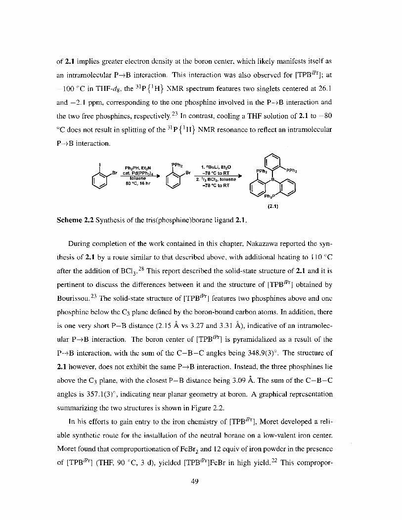
The tris(phosphine)borane ligand [TPBPh] (2.1) is prepared by low temperature ortho-
lithiation of 2-Ph 2PC6H4Br with "BuLi and subsequent addition of 1/3 equiv of BCl 3 at
-78 'C (Scheme 2.2). Isolated as a white powder in ca. 90% yield, 2.1 is soluble in
THF, C6H6 and chlorinated solvents. Ligand 2.1 is thermally robust; no decomposition
was observed after heating a THF solution of 2.1 to 100 'C over the period of 1 week.
The room temperature 31P {1 H} NMR spectrum of 2.1 in CDC13 features a singlet at -9.0
ppm. The 11B {1 H} NMR resonance appears as a broad feature centered at -7.6 ppm. In
general, free triarylboranes appear at ca. 70 ppm 24,25 and triarylborane-phosphine adducts
appear at ca. -10 ppm. 26,27 The significantly upfield shifted 11B { H} NMR resonance
48
of 2.1 implies greater electron density at the boron center, which likely manifests itself as
an intramolecular P-±B interaction. This interaction was also observed for [TPBiPr]; at
-100 'C in THF-d8 , the 3 1P { H} NMR spectrum features two singlets centered at 26.1
and -2.1 ppm, corresponding to the one phosphine involved in the P-+B interaction and
the two free phosphines, respectively. 23 In contrast, cooling a THF solution of 2.1 to -80
'C does not result in splitting of the 3 1P {1 H} NMR resonance to reflect an intramolecular
P-+B interaction.
Ph 2PH, Et 3N PPh 2 1. nBuLi, Et 2OBr cat. Pd(PPh3 )4 J Br -78 "C to RT PPh 2 PPh2
toluene 2. 1/3 BC 3, toluene B80 "C, 16 hr -78 "C to RT
(2.1)
Scheme 2.2 Synthesis of the tris(phosphine)borane ligand 2.1.
During completion of the work contained in this chapter, Nakazawa reported the syn-
thesis of 2.1 by a route similar to that described above, with additional heating to 110 'C
after the addition of BCl 3 -28 This report described the solid-state structure of 2.1 and it is
pertinent to discuss the differences between it and the structure of [TPBiPr] obtained by
Bourissou.23 The solid-state structure of [TPBiPr] features two phosphines above and one
phosphine below the C3 plane defined by the boron-bound carbon atoms. In addition, there
is one very short P-B distance (2.15 A vs 3.27 and 3.31 A), indicative of an intramolec-
ular P-*B interaction. The boron center of [TPBiPr] is pyramidalized as a result of the
P-+B interaction, with the sum of the C-B-C angles being 348.9(3)'. The structure of
2.1 however, does not exhibit the same P-MB interaction. Instead, the three phosphines lie
above the C3 plane, with the closest P-B distance being 3.09 A. The sum of the C-B-C
angles is 357.1(3)0, indicating near planar geometry at boron. A graphical representation
summarizing the two structures is shown in Figure 2.2.
In his efforts to gain entry to the iron chemistry of [TPBiPr], Moret developed a reli-
able synthetic route for the installation of the neutral borane on a low-valent iron center.
Moret found that comproportionation of FeBr 2 and 12 equiv of iron powder in the presence
of [TPBiPr] (THF, 90 'C, 3 d), yielded [TPBiPr]FeBr in high yield. 22 This compropor-
49

P2 P above C3 plane, 1 below 3 P above C3 plane
Shortest P-B = 2.15 A B B Shortest P-B = 3.09 AI(C-B-C) = 348.9(3)" 1 P(C-B-C) = 357.1(3)*
P
[TPB"Pj [TPBPh] (2.1)
Figure 2.2 Graphical representations of the solid-state structures of [TPBiPr] (left) and 2.1(right). The C3 plane is defined by the three carbon atoms bound to boron.
tionation method is readily applied to the generation of [TPBPh]FeCl (2.2), as shown in
Scheme 2.3. While free 2.1 is thermally stable in THF solution (vide supra), under the
reducing conditions described above, an inconsistent and significant amount of PPh 3 is
formed via B-Caryl bond cleavage of 2.1. The formation of PPh3 is dramatically attenu-
ated by reducing the amount of iron powder and decreasing the reaction temperature. Thus,
heating a THF slurry of 2.1, FeCl2, and 3 equiv of iron powder to 70 'C over 3 d yielded
2.2 as a dark brown powder in 75% yield. Once isolated, 2.2 is readily soluble in THF and
sparingly soluble in toluene and C6H6-
Cl
PP Ph p-Fe,~PP P FCI2, 3 equv Fe2 e Ph2 Dark brown powder
B 70 C,F3 d B 75% yield, S = 312
(2.2)
Scheme 2.3 Synthesis of the tris(phosphine)borane iron complex 2.2.
Complex 2.2 is paramagnetic, with broad resonances in the 1H NMR spectrum rang-
ing from 35 to -25 ppm. The Evans method solution magnetic moment measurement
(peff = 4.0 pB, THF-d8 , 25 'C) is slightly higher than the spin-only value of 3.9 YB for
three unpaired electrons. This S = 3/2 ground state is consistent with that observed for
[TPBiPr]FeBr (Scheme 2. 1).22 X-ray crystallographic structure determination of 2.2 con-
firmed its assignment as a monomeric iron tris(phosphine)borane complex (Figure 2.3).
Complex 2.2 crystallizes in the monoclinic space group P21/c, with one molecule in the
asymmetric unit. The geometry at iron is best described as distorted trigonal bipyramidal
(,r = 0.85),29 with a nearly linear B-Fe-Cl linkage, at 175.64(4)0. The distortion from a
50

trigonal bipyramidal geometry is reflected in the inequivalent P-Fe-P angles (124.40(2)'
vs 106.66(2)0 and 110.99(2)') and the non-90' B-Fe-P angles (74.13(4) - 77.98(4)').
These deviations may arise from an electronic distortion, but could also result from the
steric requirements of the ligand framework. Indeed, examination of the crystal structure
shows that of the six phenyl groups bound to the phosphorus atoms, three groups reside
above the P3 plane, two groups are orthogonal to the P3 plane and one group lies in the P3
plane. This last phenyl group is located within the largest P-Fe-P angle. The Fe-Cl dis-
tance of 2.2713(4) A is typical and the elongated Fe-P distances (2.3325(4) - 2.3622(4)
A) are as expected for a high-spin complex.
C ISelected Bond Lengths (A) and Angles (0)
Fe Fe-P (avg) = 2.3466(4)PI-Fe-P2 = 124.40(2)
P1 PI-Fe-P3 = 106.66(2)P2-Fe-P3 = 110.99(2)
Fe-B = 2.542(2)X(C-B-C) = 340.0(2)
Figure 2.3 Solid-state structure of 2.2. Thermal ellipsoids are drawn at 40% probability.Hydrogen atoms are omitted for clarity.
As discussed in the introduction, although 11B {H} NMR is a convenient tool for
assessing the electron density at boron (i.e., for comparing the relative strengths of an in-
tramolecular interaction), it is useless in the characterization of paramagnetic complexes
featuring a M-+B interaction, such as those described in this chapter. The M-B distance
supports the presence or absence of a M-+B interaction, however the distance alone is not
a reliable parameter to compare the magnitude of the interaction. 30 For these complexes,
the sum of the (C-B-C) angles should also be considered. In 2.2, the Fe-B distance of
2.542(2) A is long, however the boron is pyramidalized (E(C-B-C) = 340.0(2)'), indi-
cating an interaction between iron and boron centers. A comparison of selected metrical
parameters of 2.2 and [TPB'r]FeBr is given in Table 2.1.
51
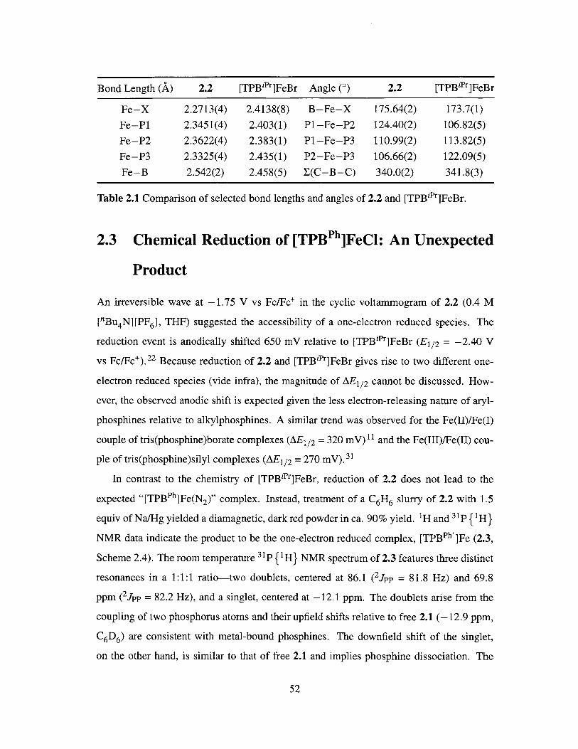
Bond Length (A) 2.2 [TPBiPr]FeBr Angle (0) 2.2 [TPBiPr]FeBr
Fe-X 2.2713(4) 2.4138(8) B-Fe-X 175.64(2) 173.7(1)
Fe-PI 2.3451(4) 2.403(1) P1-Fe-P2 124.40(2) 106.82(5)
Fe-P2 2.3622(4) 2.383(1) P1-Fe-P3 110.99(2) 113.82(5)
Fe-P3 2.3325(4) 2.435(1) P2-Fe-P3 106.66(2) 122.09(5)
Fe-B 2.542(2) 2.458(5) E(C-B-C) 340.0(2) 341.8(3)
Table 2.1 Comparison of selected bond lengths and angles of 2.2 and [TPBiPr]FeBr.
2.3 Chemical Reduction of [TPBPh]FeCl: An Unexpected
Product
An irreversible wave at -1.75 V vs Fc/Fc' in the cyclic voltammogram of 2.2 (0.4 M
["Bu 4 N][PF6 ], THF) suggested the accessibility of a one-electron reduced species. The
reduction event is anodically shifted 650 mV relative to [TPBiPr]FeBr (E1 / 2 = -2.40 V
vs Fc/Fc'). 2 2 Because reduction of 2.2 and [TPBiPr]FeBr gives rise to two different one-
electron reduced species (vide infra), the magnitude of AE1/2 cannot be discussed. How-
ever, the observed anodic shift is expected given the less electron-releasing nature of aryl-
phosphines relative to alkylphosphines. A similar trend was observed for the Fe(II)/Fe(I)
couple of tris(phosphine)borate complexes (AE 1/ 2 = 320 mV)1 1 and the Fe(III)/Fe(II) cou-
ple of tris(phosphine)silyl complexes (AE 1 / 2 = 270 mV). 3 '
In contrast to the chemistry of [TPBiPr]FeBr, reduction of 2.2 does not lead to the
expected "[TPBPh]Fe(N2)" complex. Instead, treatment of a C6 H6 slurry of 2.2 with 1.5
equiv of Na/Hg yielded a diamagnetic, dark red powder in ca. 90% yield. 1H and 31p {1 H}
NMR data indicate the product to be the one-electron reduced complex, [TPBPh']Fe (2.3,
Scheme 2.4). The room temperature 3 1P {1 H} NMR spectrum of 2.3 features three distinct
resonances in a 1:1:1 ratio-two doublets, centered at 86.1 ( 2JPP = 81.8 Hz) and 69.8
ppm (2JPP = 82.2 Hz), and a singlet, centered at -12.1 ppm. The doublets arise from the
coupling of two phosphorus atoms and their upfield shifts relative to free 2.1 (-12.9 ppm,
C6 D6 ) are consistent with metal-bound phosphines. The downfield shift of the singlet,
on the other hand, is similar to that of free 2.1 and implies phosphine dissociation. The
52
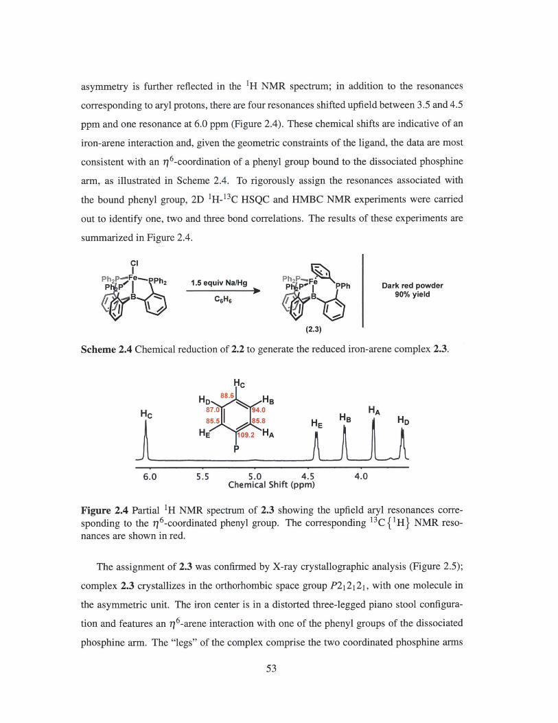
asymmetry is further reflected in the 'H NMR spectrum; in addition to the resonances
corresponding to aryl protons, there are four resonances shifted upfield between 3.5 and 4.5
ppm and one resonance at 6.0 ppm (Figure 2.4). These chemical shifts are indicative of an
iron-arene interaction and, given the geometric constraints of the ligand, the data are most
consistent with an 16 -coordination of a phenyl group bound to the dissociated phosphine
arm, as illustrated in Scheme 2.4. To rigorously assign the resonances associated with
the bound phenyl group, 2D 'H-'3 C HSQC and HMBC NMR experiments were carried
out to identify one, two and three bond correlations. The results of these experiments are
summarized in Figure 2.4.
I
Ph 2 PFe 42 1.5 equiv NaFHg P F PPh Dark red powder
7. B C61-1 B 90% yield
(2.3)
Scheme 2.4 Chemical reduction of 2.2 to generate the reduced iron-arene complex 2.3.
Hc
HD 88.6 HB
H 870 94.0 HA85.5 I 85.8 HE HB HD
HE 109.2 HA
P
6.0 5.5 5.0 4.5 4.0Chemical Shift (ppm)
Figure 2.4 Partial 'H NMR spectrum of 2.3 showing the upfield aryl resonances corre-sponding to the 1 6-coordinated phenyl group. The corresponding 13C {'H} NMR reso-nances are shown in red.
The assignment of 2.3 was confirmed by X-ray crystallographic analysis (Figure 2.5);
complex 2.3 crystallizes in the orthorhombic space group P212121, with one molecule in
the asymmetric unit. The iron center is in a distorted three-legged piano stool configura-
tion and features an 11 6 -arene interaction with one of the phenyl groups of the dissociated
phosphine arm. The "legs" of the complex comprise the two coordinated phosphine arms
53
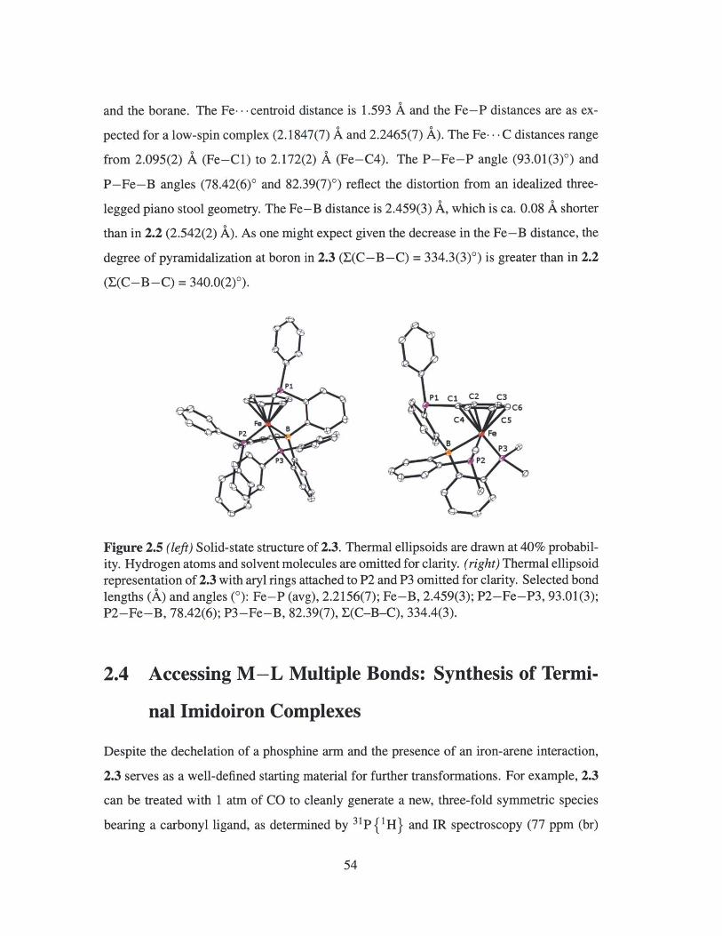
and the borane. The Fe... centroid distance is 1.593 A and the Fe-P distances are as ex-
pected for a low-spin complex (2.1847(7) A and 2.2465(7) A). The Fe... C distances range
from 2.095(2) A (Fe-Cl) to 2.172(2) A (Fe-C4). The P-Fe-P angle (93.01(3)0) and
P-Fe-B angles (78.42(6)' and 82.39(7)0) reflect the distortion from an idealized three-
legged piano stool geometry. The Fe-B distance is 2.459(3) A, which is ca. 0.08 A shorter
than in 2.2 (2.542(2) A). As one might expect given the decrease in the Fe-B distance, the
degree of pyramidalization at boron in 2.3 (E(C-B-C) = 334.3(3)') is greater than in 2.2
(E(C-B-C) = 340.0(2)0).
PI
P2 B
P3
P1 Cl CZ C3C6
C4 C5
5P3
P2
Figure 2.5 (left) Solid-state structure of 2.3. Thermal ellipsoids are drawn at 40% probabil-ity. Hydrogen atoms and solvent molecules are omitted for clarity. (right) Thermal ellipsoidrepresentation of 2.3 with aryl rings attached to P2 and P3 omitted for clarity. Selected bondlengths (A) and angles (0): Fe-P (avg), 2.2156(7); Fe-B, 2.459(3); P2-Fe-P3, 93.01(3);P2-Fe-B, 78.42(6); P3-Fe-B, 82.39(7), E(C-B-C), 334.4(3).
2.4 Accessing M-L Multiple Bonds: Synthesis of Termi-
nal Imidoiron Complexes
Despite the dechelation of a phosphine arm and the presence of an iron-arene interaction,
2.3 serves as a well-defined starting material for further transformations. For example, 2.3
can be treated with 1 atm of CO to cleanly generate a new, three-fold symmetric species
bearing a carbonyl ligand, as determined by 31p{ 'H} and IR spectroscopy (77 ppm (br)
54
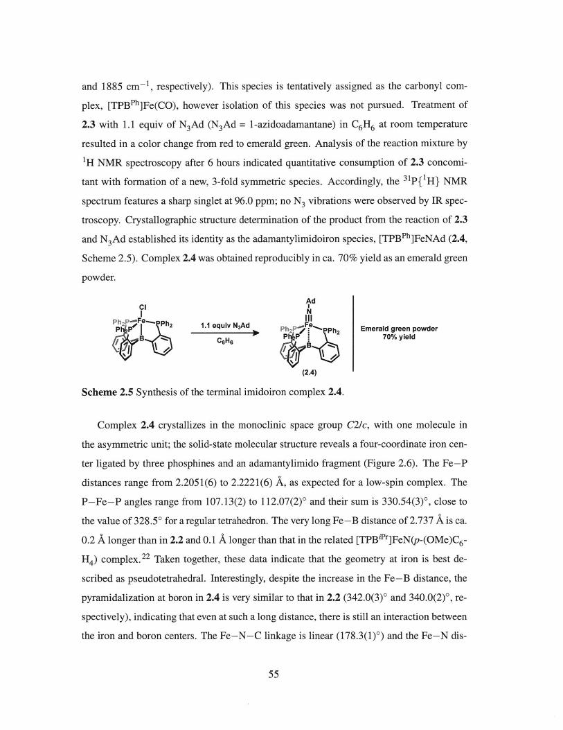
and 1885 cm- 1, respectively). This species is tentatively assigned as the carbonyl com-
plex, [TPBPh]Fe(CO), however isolation of this species was not pursued. Treatment of
2.3 with 1.1 equiv of N3Ad (N3Ad = 1-azidoadamantane) in C6H6 at room temperature
resulted in a color change from red to emerald green. Analysis of the reaction mixture by
1H NMR spectroscopy after 6 hours indicated quantitative consumption of 2.3 concomi-
tant with formation of a new, 3-fold symmetric species. Accordingly, the 31p{'H} NMR
spectrum features a sharp singlet at 96.0 ppm; no N3 vibrations were observed by IR spec-
troscopy. Crystallographic structure determination of the product from the reaction of 2.3
and N 3 Ad established its identity as the adamantylimidoiron species, [TPBPh]FeNAd (2.4,
Scheme 2.5). Complex 2.4 was obtained reproducibly in ca. 70% yield as an emerald green
powder.
AdCI I
N-F III
1.1 equlve- N3Ad FeP1P,2 PO P 1.1 equiv N3Ad Ph2 / Ph2 Emerald green powderB CFHr 70% yield
(2.4)
Scheme 2.5 Synthesis of the terminal imidoiron complex 2.4.
Complex 2.4 crystallizes in the monoclinic space group C2/c, with one molecule in
the asymmetric unit; the solid-state molecular structure reveals a four-coordinate iron cen-
ter ligated by three phosphines and an adamantylimido fragment (Figure 2.6). The Fe-P
distances range from 2.2051(6) to 2.2221(6) A, as expected for a low-spin complex. The
P-Fe-P angles range from 107.13(2) to 112.07(2)' and their sum is 330.54(3)', close to
the value of 328.50 for a regular tetrahedron. The very long Fe-B distance of 2.737 A is ca.
0.2 A longer than in 2.2 and 0.1 A longer than that in the related [TPB'Pr]FeN(p-(OMe)C 6-
H4 ) complex. 22 Taken together, these data indicate that the geometry at iron is best de-
scribed as pseudotetrahedral. Interestingly, despite the increase in the Fe-B distance, the
pyramidalization at boron in 2.4 is very similar to that in 2.2 (342.0(3)' and 340.0(2)', re-
spectively), indicating that even at such a long distance, there is still an interaction between
the iron and boron centers. The Fe-N-C linkage is linear (178.3(1)') and the Fe-N dis-
55
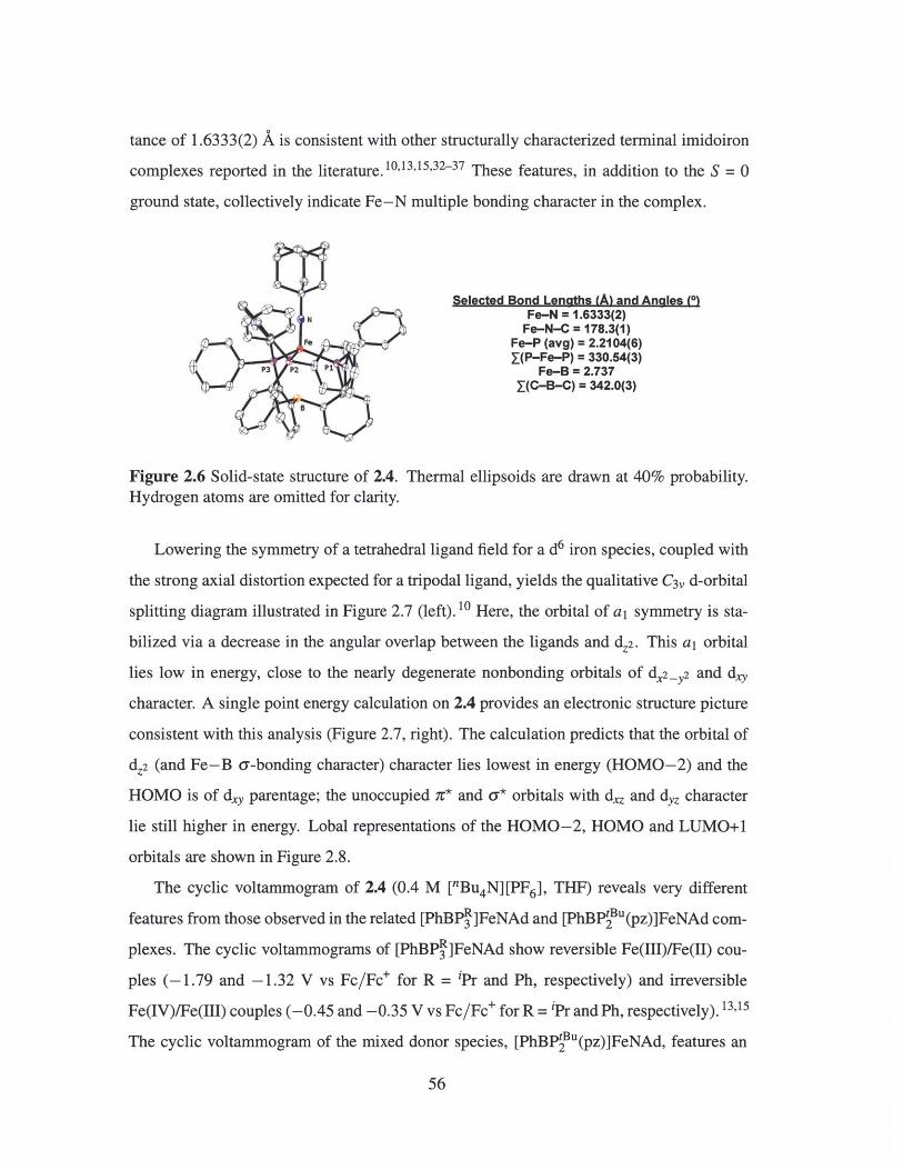
tance of 1.6333(2) A is consistent with other structurally characterized terminal imidoiron
complexes reported in the literature. 10,13,15,32-37 These features, in addition to the S = 0
ground state, collectively indicate Fe-N multiple bonding character in the complex.
Selected Bond Lengths (A) and Anales (0)N Fe-N = 1.6333(2)
Fe-N-C = 178.3(1)Fe-P (avg) = 2.2104(6)J(P-Fe-P) = 330.54(3)
P3 P2 P Fe-B = 2.737I(C-B-C) = 342.0(3)
B
Figure 2.6 Solid-state structure of 2.4. Thermal ellipsoids are drawn at 40% probability.Hydrogen atoms are omitted for clarity.
Lowering the symmetry of a tetrahedral ligand field for a d6 iron species, coupled with
the strong axial distortion expected for a tripodal ligand, yields the qualitative C3, d-orbital
splitting diagram illustrated in Figure 2.7 (left).10 Here, the orbital of a, symmetry is sta-
bilized via a decrease in the angular overlap between the ligands and dZ2 . This a, orbital
lies low in energy, close to the nearly degenerate nonbonding orbitals of d2-_y2 and dy
character. A single point energy calculation on 2.4 provides an electronic structure picture
consistent with this analysis (Figure 2.7, right). The calculation predicts that the orbital of
dz2 (and Fe-B a-bonding character) character lies lowest in energy (HOMO-2) and the
HOMO is of dy parentage; the unoccupied 7g* and a* orbitals with dz and dyz character
lie still higher in energy. Lobal representations of the HOMO-2, HOMO and LUMO+l
orbitals are shown in Figure 2.8.
The cyclic voltammogram of 2.4 (0.4 M [Bu4N][PF6], THF) reveals very different
features from those observed in the related [PhBP ]FeNAd and [PhBPtu(pz)]FeNAd com-
plexes. The cyclic voltammograms of [PhBPR]FeNAd show reversible Fe(III)/Fe(II) cou-
ples (-1.79 and -1.32 V vs Fc/Fc+ for R = iPr and Ph, respectively) and irreversible
Fe(IV)/Fe(III) couples (-0.45 and -0.35 V vs Fc/Fc+ for R = iPr and Ph, respectively).13,15
The cyclic voltammogram of the mixed donor species, [PhBPtu(pz)]FeNAd, features an
56

Td c3V
IIIFe
e 4 - " e (;*, *)a,
a1 (nb)
e ft e (nb)
s=1 s=O
-1.72 eVxz
-3.80 eVX2.y2
-1.65 eVyz
-3.78 eVXY -3.91 eV
Z2
Figure 2.7 (left) Qualitative d-orbital splitting diagrams illustrating the predicted ground-state electronic structures of Td and C3, symmetric structures for d6 configurations. Forthe C3, species, the orbital of a, symmetry with dz2 character lies close in energy to thenonbonding orbitals of d,2-Y2 and d.y character. (right) Calculated electronic structure(DFT, Gaussian 09, M06L, 6-31 G(d,p)) of imidoiron 2.4.
irreversible Fe(III)/Fe(II) couple (-2.2 V vs Fc/Fc+) and a reversible Fe(IV)/Fe(III) cou-
ple (-0.72 V vs Fc/Fc+).33 In contrast, the cyclic voltammogram of 2.4 exhibits two redox
features: a reversible event centered at -0.42 V vs Fc/Fc+ and a second, quasi-reversible
event centered at 0.38 V vs Fc/Fc+ (Figure 2.9). The quasi-reversible wave becomes fully
reversible upon increasing the scan rate to 500 mV/s. The open circuit potential rests at
-0.58 V vs Fc/Fc+ and so these waves can be ascribed to the formation of the cationic and
dicationic imidoiron complexes, respectively.
Attempts to chemically generate the dicationic adamantylimidoiron species have, thus
xy
HOMO
xz
LUMO+1
Figure 2.8 Surface plots of the orbitals of dZ2 (and Fe-B a--bonding) parentage (HOMO-2), dy parentage (HOMO), and dz parentage (LUMO+1) (DFT, Gaussian 09, M06L, 6-31 G(d,p), isovalue = 0.004) for imidoiron 2.4.
57
HOMO-2
Z2

[[TPBPh]FeNAd]+ 2 / [[TPBPh]FeNAd]+E1/2 =0.38 V
[TPBPh]FeNAd I [[TPBPh]FeNAd]+E1/2 -0.42 V
0.6 0.4 0.2 0 -0.2 -0.4 -0.6 -0.8
Potential vs Fc/Fc* (V)
Figure 2.9 Cyclic voltammogram of neutral imidoiron complex 2.4 (0.4 M [nBu 4 N][PF6 ],THF, scan rate = 100 mV/s).
far, been unsuccessful. However, the monocationic complex [[TPBPh]FeNAd][PF 6 ] ([2.5]-
[PF 6]) can be generated in moderate yield via treatment of a THF solution of 2.4 with 1.1
equiv of FcPF6 (Scheme 2.6). Complex [2.5] [PF 6] is paramagnetic with broad resonances
ranging from 23 to -10 ppm. The Evans method solution magnetic moment measurement
(pewf = 1.8 gB, THF-d8 , 25 'C) is slightly higher than the spin-only value of 1.7 pB for
one unpaired electron and implies an S = 1/2 ground state. Single crystals of [2.5][PF6 ]
invariably suffered from severe disorder, preventing an unambiguous assignment of the
number of counterions associated with the adamantylimidoiron species crystallized. To
aid in assignment, the larger [BAr ] counterion was employed ([BAr!] = tetrakis[3,5-
bis(trifluoromethyl)phenyl]borate); treatment of a diethyl ether slurry of [2.5][PF6 ] with
an excess of NaBAr yielded [2.5]F[BAr] in near quantitative yield.
Gratifyingly, crystals of [2.5][BArF] do not suffer severe disorder and the identity of
[2.5][BAr F] was confirmed by X-ray crystallographic analysis (Figure 2.10). Cationic
[2.5][BAr ] crystallizes in the triclinic space group P!, with one molecule in the asym-
metric unit. The core structure is very similar to that of 2.4: a four-coordinate, pseudote-
trahedral iron center ligated by three phosphines and an adamantylimido moiety. Upon
oxidation from 2.4 to [2.5][BAr ], the Fe-N-C angle contracts ca. 7' (178.3(1)' vs
58

Ad Ad PFN NIII III
Ph 2P Ph 1.1 equiv6FcPF Ph 2PFe. - Ph 2 Olive powderPTHF Ph 2 40% yield, S = 1/2
excess [2.5][PF6]NaBAr 4F
Et 2O [2.5][BAr 4F]
Scheme 2.6 Chemical oxidation of 2.4 to synthesize the cationic, terminal imidoironspecies [2.5] [PF 6]. Subsequent anion exchange generates [2.5] [BAri].
171.0(2)') and the Fe-N distance remains essentially the same (1.6333(2) A vs 1.6422
A). Little structural change is expected for the Fe-N-C linkage, as an electron should be
removed from a largely nonbonding orbital (Figure 2.7, right). The Fe-B distance is very
long in [2.5][BAr ] (3.136 A) and is ca. 0.4 A longer than that of 2.4; the sum of the
C-B-C angles is 354.2(2)0, indicating near planarity at the boron center. These metrical
parameters make [2.5][BArF] quite unique among the [TPBR]Fe complexes prepared in
the Peters group, in that there is unequivocally no interaction between the iron and boron
centers.21'22 The P-Fe-P angles of [2.5][BAr.] range from 101.92(1) to 112.70(1)0 and
their sum is 317.14(2)0, less than that that expected for a regular tetrahedron (328.5').
Interestingly, the average Fe-P bond length increases ca. 0.1 A upon oxidation. This
change is counterintuitive, as the unpaired spin should reside in an orbital of primarily non-
bonding character. A similar observation was made for the related [PhBPPh]FeNAd and
[[PhBP h]FeNAd][nBu 4 N] complexes.13 The phenomenon was rationalized on the basis
that the divalent iron center can more strongly ir-backbond into the a-antibonding orbitals
of the tripodal ligand than the trivalent iron center by virtue of its d6 (versus d5) configura-
tion. This reasoning may also be applied to [2.5][BAr7]; consistent with this argument is
that the average P-C bonds of 2.4 are ca. 0.02 A longer than those of [2.5] [BAr] (1.84 Avs 1.82 A).
The X-band EPR spectrum of [2.5][PF 6], recorded in 2-MeTHF at 10 K, is shown
in Figure 2.11. The EPR signal is rhombic, with gi, g2 and g3 values of 2.370, 2.085
and 1.975, respectively. The gis, value of 2.143 suggests that the unpaired spin resides
59

Selected Bond Lengths (A) and Angles (*)N Fe-N = 1.642(1)
Fe-N-C = 171.0(2)Fe-P (avg) = 2.2913(4)P(P-Fe-P) = 317.14(2)
2 1Fe-B = 3.1362(C-B-C) = 354.2(2)
Figure 2.10 Solid-state structure of [2.5][BAr ]. Thermal ellipsoids are drawn at 40%probability. Hydrogen atoms, the BAr counterion and the minor component of the disor-dered adamantyl group are omitted for clarity.
in an orbital orthogonal to the Fe-N vector. If the unpaired electron is located in either
the d.2_y2 or dy orbital (see Figure 2.8 for the relative order of the energy levels), then
rotation of one of these d-orbitals moves the unpaired electron into an occupied orbital
(i.e., dx2 _y2 -+ dy and dy -+ dx2_Y2), leading to a magnetic field that is in concert with
the applied field. A smaller applied magnetic field is required and the calculated g value
will therefore be greater than that of a free electron (g = 2.0).38 For this discussion, the
contribution from the rotation of d,2 _y2 or dy into the unoccupied dz or dyz orbitals of
cation 2.5 are omitted because they are much higher in energy and the spin-orbit effects
between d,2_y2 and dy should be dominant. These parameters are similar to the related
[BPR]FeNR imidoiron(III) complexes, 10,33 suggesting a similar electronic configuration
in which the unpaired electron resides in one of the nonbonding d.2_y2 and d'Y orbitals.
The a-- and 7r-nonbonding character of this singly occupied molecular orbital (SOMO)
implies that cation 2.5 should have mostly metalloradical character. A single point energy
calculation on 2.5 supports this interpretation, with a Mulliken spin density of 1.54 at the
iron center (Figure 2.11, right).
These results are in stark contrast with those obtained for the isoelectronic nitridoiron
complex [TPBPr]FeN prepared by Moret. 39 This species is highly unstable, but can be
generated by photolysis of the azidoiron precursor [TPBipr]FeN 3 in frozen solution and de-
tected by EPR. The X-band EPR spectrum of the nitridoiron species, shown in Figure 2.12,
60

-Fit
2500 300 3500 4000Magnetic Field (G) Spin density on Fe = 1.54,
N = -0.30, B = -0.10
Figure 2.11 (left) Experimental (black) and simulated (red) X-band EPR spectrum of[2.5][PF 6] (2-MeTHF, 10 K). (right) Spin density surface calculated for 2.5 (DFT, Gaus-sian 09, M06L, 6-31 1+G(d,p), isovalue = 0.003).
is well simulated as an axial signal (77 K, toluene, g1 = 1.999, gi = 2.031) with hyperfine
coupling to N (All = 19 MHz), B (All = 80 MHz, A1 = 21.6 MHz) and three P nuclei (All
= 42.0 MHz, A1 = 46.5 MHz). These parameters indicate a ground state electronic config-
uration in which the Fe-N a-antibonding SOMO is stabilized by delocalization onto the
boron atom. The calculated spin density of [TPBLpr]FeN also indicates significant delocal-
ization onto the boron atom (Figure 2.12, right). The difference in the electronic structures
of [2.5] [PF6] and [TPBr]FeN likely arises as a result of the lower a-donor strength of the
adamantylimido ligand relative to the nitrido ligand, thereby stabilizing the orbital of d,2
character and rendering it mostly nonbonding.
- Fit
M200 Magnetic Field (G) Spin density on Fe = 0.16,
Figure 2.12 (left) Experimental (black) and simulated (red) X-band EPR spectrum of[TPBipr]FeN (2-MeTHF, 10 K). (right) SOMO calculated for [TPBLr]FeN (DFT, Gaus-sian 09, B3LYP, 6-311 +G(d,p), isovalue = 0.004).
61

2.5 Mossbauer Spectroscopic Studies
The M6ssbauer spectra of 2.3, 2.4 and [2.5] [BArr] obtained at 5 K and zero applied field
are shown in Figure 2.13. Although the isomer shift is often used to identify a particular
iron valence state, strong covalency can compress the range of isomer shifts,40 resulting in
an ambiguous assignment of the iron valence. In addition, the local geometry can signifi-
cantly affect both the isomer shift and the quadrupole splitting parameters. 41-43 Therefore,
only the spectra of 2.4 and [2.5] [BArr] can be internally compared.
[TPBPh'Fe (2.3) 6 = 0.45 mm/s
'%VTo
= 1.29 mm/s
[TPBPh]FeNAd (2.4) 6 -0.04 mm/s
7 7
AEO = 1.27 mm/s
([2.5][BAr4F])p . I I I . I
-4 -2 0 2 4
Velocity (mmis)
Figure 2.13 (top) Experimental (black) and simulated (red) M6ssbauer spectrum of 2.3.(center) Experimental (black) and simulated Mbssbauer spectrum of 2.4. (bottom) Exper-imental (black) and simulated (red) M6ssbauer spectrum of [2.5] [BAr I]. All spectra werecollected at 5 K and zero applied field.
The spectrum of 2.3 consists of a quadrupole doublet centered at 3 = 0.45 ml/s, with
a quadrupole splitting of AEQ = 1.29 mm/s. The line widths are slightly asymmetric, with
62

W = 0.26 mm/s and y = 0.25 mm/s (Figure 2.13, top). The spectrum of 2.4 features a
quadrupole doublet centered at 3 = -0.04 mm/s, with a quadrupole splitting of AEQ =
1.27 mm/s (Figure 2.13, center). Finally, the spectrum of [2.5][BArF] shows a quadrupole
doublet centered at 3 = 0.19 mm./s, with a quadrupole splitting of AEQ = 1.37 mm/s. This
spectrum is significantly broader and more asymmetric than the other two, with y = 0.44
mm/s and YR = 0.48 mm/s (Figure 2.13, bottom). The M6ssbauer spectrum of [2.5] [BAr4]
measured in an externally applied field (54 mT) is identical to that obtained in zero applied
field. The isomer shifts of 2.4 and [2.5][BArF] (-0.04 mm/s vs 0.19 mm/s) shift positive
as the overall formal oxidation state of iron increases from iron(II) to iron(III). This trend
mirrors the decrease in s-electron density at iron upon removal of electrons from the system.
The isomer shift of 2.3 is much more positive than the other two complexes (0.45 mm/s),
however the geometry of this complex is very different from the imido complexes and so
the significance of this isomer shift cannot be discussed without first obtaining Missbauer
spectra of similar complexes for comparison.
2.6 Conclusions and Future Work
In this chapter, the preparation and characterization of a series of iron tris(phosphine)borane
complexes were described. In contrast to the related [TPBiPr]FeBr complex, reduction of
[TPBPh]FeCl yields a one-electron reduced species featuring an 776-arene interaction, as a
result of dechelation of a phosphine arm. This structural motif is maintained in both the
solid and solution states. The one-electron reduced species serves as a well-defined material
for further transformations, most notably for the decomposition of adamantylazide to yield
a terminal imidoiron complex. Interestingly, this imidoiron complex can be oxidized to
yield the cationic imidoiron species in which there is no interaction between the iron and
boron centers. This species has a different ground electronic state than the isoelectronic
[TPBiPr]FeN complex, thereby showcasing the ability of the tris(phosphine)borane ligand
to stabilize various electronic structures by an axial delocalization of electrons onto the
boron center.
Qualitative inspection of the molecular orbital diagram in Figure 2.7 suggests that the
63

dicationic imidoiron species can be generated; this is supported by electrochemical studies
of [TPBPh]FeNAd (Figure 2.9). The isolation of such a dicationic species would be of
interest in relation to the tris(phosphine)borate imidoiron chemistry reported by the Peters
group and the tris(carbene)borate imidoiron chemistry described by the Smith group. To
our knowledge, the addition of the dicationic species would provide the first example of a
pseudotetrahedral imidoiron complex in three different oxidation states.
Although the Peters group has begun study of catalytic reactions mediated by the re-
lated [TPBiPr]FeN 2 complex, one could envision that even if a phosphine arm dechelates
during a catalytic process, the steric bulk of the ligand may slow or even preclude catalysis
and make the system less amenable to various larger substrates of interest (e.g. a 1,2-
disubstituted olefin in the case of hydrogenation catalysis). Complex [TPBPh']Fe would be
an ideal candidate for catalytic studies, as the ij 6 -arene interaction is a stable, yet labile,
configuration. In addition, dechelation of one of the phosphine arms has already occurred
in [TPBPh']Fe, thereby relieving some of the steric strain of the system and potentially
providing a large substrate other approaches to the iron center.
2.7 Experimental Methods
2.7.1 General Considerations
All manipulations were carried out using standard Schlenk or glovebox techniques under a
dinitrogen atmosphere. Unless otherwise noted, solvents were dried and deoxygenated by
sparging with argon and passing through activated alumina in a solvent purification system
from SG Waters USA, LLC (Nashua, NH). Non-halogenated solvents were tested with a
standard purple solution of sodium benzophenone ketyl in tetrahydrofuran in order to con-
firm effective oxygen and moisture removal. o-Ph2(C6H4)Br 44 and NaBArF45 (BArI -
tetrakis[3,5-bis(trifluoromethyl)phenyl]borate) were prepared according to literature meth-
ods. All other reagents were purchased from commercial suppliers and used without further
purification. Elemental analyses were performed by Midwest Microlab, LLC (Indianapolis,
IN) and Robertson Microlit Laboratories, Inc (Ledgewood, NJ). Deuterated solvents were
64

purchased from Cambridge Isotope Laboratories, Inc., degassed, and dried over activated
3-A molecular sieves prior to use.
2.7.2 Spectroscopic Measurements
Varian 300, 400 and 500 MHz spectrometers were used to record 'H, 13C, 3 1P and "B
NMR spectra at room temperature, unless otherwise noted. 1H and 13C NMR chemical
shifts were referenced to the residual solvent peaks. 3 1P NMR chemical shifts were ref-
erenced to external 85% phosphoric acid (3 = 0 ppm). 11B NMR chemical shifts were
referenced to external BF 3 * Et2 O (8 = 0 ppm). Solution magnetic moment measurements
were determined by the method of Evans. 4 6,4 7 To determine the error in these measure-
ments, an error analysis was performed and the error bars were established at 95% con-
fidence using regression analysis. The values are reported to two significant figures and
are understood to have an error of ± 0.1 pB. Optical spectroscopy measurements were
taken on a Cary 50 UV-vis spectrophotometer using a 1 cm two-window quartz cell sealed
with a closed cap (Starna Cells, Inc, Altascadero, CA). Infrared measurements were ob-
tained in thin films using a Bruker ALPHA FT-IR spectrometer equipped with a diamond
ATR probe and OPUS/Mentor software. X-band EPR spectra were recorded using a Bruker
EMX spectrometer at 77 K in 2-MeTHF glasses. EPR samples were prepared in a glovebox
under an N2 atmosphere in quartz EPR tubes equipped with J. Young caps. EPR spectra
were simulated using EasySpin. 48 57 Fe M6ssbauer spectra were measured with a constant
acceleration spectrometer (SEE Co., Minneapolis, MN). Isomer shifts are quoted relative to
Fe metal at room temperature. Data were analyzed and simulated with WMOSS software
(Web Research Corp., Edina, MN).
2.7.3 Electrochemistry
Electrochemical measurements were carried out in a glovebox under a dinitrogen atmo-
sphere in a one-compartment cell using a CH Instruments 630-C Electrochemistry Ana-
lyzer with CHI Version 8.09 software package. A glassy carbon electrode and platinum
wire were used as the working and auxiliary electrodes, respectively. The reference elec-
65

trode was Ag/AgNO 3 in THF. Solutions of electrolyte (0.4 M ["Bu 4 N][PF 6 ]) and analyte
were prepared in a glovebox. Experiments were conducted at room temperature. The fer-
rocene couple Fc/Fc' was used as an external reference.
2.7.4 DFT Calculations
Calculations for 2.4 and 2.5 were performed using the Gaussian09 suite of programs. 49
Single point calculations were performed with the M06L functional 5 0 and the 6-31 G(d)
basis set for all atoms of 2.4 and 6-31 l+G(d,p) basis set for all atoms of 2.5. The Mulliken
spin densities calculated for 2.5 are summarized in Table 2.2.
Atom Value Atom Value
Fe 1.537288 P -0.041476
N -0.296205 P -0.061982
B -0.105632 P -0.045213
Table 2.2 Mulliken spin densities calculated for 2.5. For clarity, only the values for the
heteroatoms are shown.
2.7.5 Preparation of [TPBPh] (2.1)
The ligand was prepared by modification of the recently reported literature procedure. 28
"BuLi (13.5 mL, 1.6 M in hexane, 21.60 mmol) was added to a solution of o-Ph2 (C6 H4 )Br
(7.38 g, 21.60 mmol) in OEt2 (100 mL) at -78 'C. The slurry was stirred for 10 min,
then warmed to room temperature and stirred for 1.5 h, yielding a light yellow slurry. The
volatiles were removed in vacuo, the residual solids dissolved in toluene and the solution
recooled to -78 'C. BCl 3 was added (7.2 mL, I M in heptane, 7.2 mmol), resulting in a
slightly darker yellow mixture. The reaction mixture was slowly warmed to room temper-
ature (12 h). The volatiles were removed in vacuo and the residue triturated with pentane.
The residual solids were then slurried in CH2 Cl 2 and filtered through Celite. The filtrate
was concentrated to ca. 50% of its original volume and pentane was added. The result-
ing white precipitate was collected and washed with pentane (5.16 g, 90%). The 1H and
3 1P {'H} NMR spectra match those previously reported in the literature.
66

2.7.6 Preparation of [TPBPh]FeCJ (2.2)
A Schlenk tube was charged with 2.2 (922.8 mg, 1.24 mmol), FeCl2 (197.9 mg, 1.56
mmol), iron powder (176.4 mg, 3.16 mmol) and THF (50 mL). The reaction was stirred
vigorously for 3 d at 70 'C, during which time the slurry turned dark brown. The mixture
was filtered through Celite to remove the excess iron powder and the volatiles removed in
vacuo. The residual solids were triturated with toluene, slurried in CH 2C12 and filtered to
collect a dark brown powder (841.2 mg, 76%). Crystals suitable for X-ray analysis were
grown by slow evaporation of a C6 H6 solution. 'H NMR (300 MHz, THF-d8 ) 3 34.23,
23.91, 9.89, 7.30, 4.73, 2.31, -23.84. peff (THF-d8 , Evans method, 25 C): 4.0 AB. Anal.
Calcd for C54H42BClFeP 3 : C, 73.21; H, 4.78. Found: C, 72.96; H, 4.62.
2.7.7 Preparation of [TPBPh']Fe (2.3)
Sodium (3.4 mg, 0.15 mmol) and mercury (500 mg) were stirred vigorously with C6 H6 (1
mL). A slurry of 2.2 (95.1 mg, 0.11 mmol) in C6 H6 (10 mL) was added and the reaction
mixture stirred for 6 h at room temperature. The resulting dark red mixture was filtered
and lyophilized (80.5 mg, 88%). Crystals suitable for X-ray analysis were grown by vapor
diffusion of OEt2 into a concentrated THF solution at -35 0 C. 'H NMR (400 MHz, C6 D6 )
3 8.38 (t, J = 8.4 Hz, 2H), 7.94 (d, J = 7.4 Hz, lH), 7.85 (t, J = 7.3 Hz, 2H), 7.59 (ddt, J =
9.6, 7.3, 3.1 Hz, 4H), 7.41 (d, J = 7.5 Hz, lH), 7.31 - 7.17 (m, 6H), 7.09 - 6.79 (m, 12H),
6.73 (dd, J = 4.4, 2.6 Hz, 3H), 6.60 (t, J = 8.6 Hz, 2H), 6.54 - 6.42 (m, 2H), 6.33 - 6.15
(m, 2H), 6.04 (t, J = 5.9 Hz, 1H), 4.42 (q, J = 6.7 Hz, 1H), 4.16 (q, J = 5.6 Hz, 1H), 3.89
(d, J = 6.1 Hz, 1H), 3.62 (q, J = 6.6 Hz, 1H). 3 C { 'H} NMR (126 MHz, C6D6 ) 3 160.5
(s), 145.7 (d, J = 7.0 Hz), 144.1 (s), 143.8 (s), 142.9 (s), 142.5 (s), 141.9 (s), 141.5 (s),
140.9 (s), 140.6 (s), 139.8 (s), 139.7 (s), 137.7 (s), 137.4 (s), 136.0 (d, J = 10.8 Hz), 135.6
(s), 135.2 (m), 134.8 (s), 134.6 (s), 132.9 (m), 132.3 (d, J = 8.7 Hz), 132.0 (d, J = 7.3 Hz),
130.9 (m), 129.2 (s), 129.0 (s), 128.7 (s), 126.9 (m), 126.3 (d, J = 8.7 Hz), 125.9 (s), 124.3
(s), 123.8 (d, J = 6.6 Hz), 123.6 (d, J = 6.5 Hz), 109.2 (d, J = 15.7 Hz), 94.0 (d, J = 14.3
Hz), 88.6 (s), 87.0 (s), 85.8 (s), 85.5 (m). 3 1P {'H} NMR (121 MHz, C6D6 ) 3 86.1 (d, J
= 81.8 Hz), 69.8 (d, J = 82.2 Hz), -12.1 (s). 11B {'H} NMR (128 MHz, C6D6) 3 15.9.
67

Anal. Calcd for C54H42BFeP3 : C, 76.26; H, 4.98. Found: C, 76.69; H, 5.59.
2.7.8 Preparation of [TPBPh]Fe(NAd) (2.4)
A mixture of 2.3 (142.6 mg, 0.17 mmol) and N3Ad (32.4 mg, 0.18 mmol) in C6H6 (10 mL)
were stirred at room temperature. The red solution turned dark green over the course of 30
min. The reaction was stirred for 6 h, frozen and lyophilized. Pentane was added and the
slurry mixed vigorously for 30 min before filtering to remove a light yellow filtrate. The
green solids were redissolved in C6 H6, filtered and lyophilized (116.3 mg, 68%). Crystals
suitable for X-ray analysis were grown by vapor diffusion of OEt 2 into a concentrated THF
solution. 1H NMR (500 MHz, toluene-d8) 3 7.82 (t, J = 7.0 Hz, 6H), 7.54 (d, J = 7.3
Hz, 3H), 7.15 (s, 9H), 7.09 - 6.95 (m, 12H), 6.70 (d, J = 7.5 Hz, 12H), 2.17 (d, J = 10.8
Hz, 3H), 1.77 (s, 3H), 1.65 (d, J = 10.5 Hz, 3H), 1.53 (s, 6H). 13C {'H} NMR (126 MHz,
toluene-d8 ) 3 160.3, 145.4, 145.1, 141.1, 140.8, 140.2, 140.0, 136.1, 132.5, 129.9, 127.2,
126.6, 126.4, 72.3, 37.9, 34.0, 28.7, 25.4. 31p { 1H} NMR (121 MHz, C6D6) 3 96.0 (s).
11B { H} NMR (128 MHz, C6D6 , 45 C) 3 39.5. UV-vis (e, C66, nm cm- 1 M- 1 ): 625
{460}, 875 {4}. Anal. Calcd for C64H57BFeNP 3 : C, 76.89; H, 5.75; N, 1.40. Found: C,
76.68; H, 5.99; N, 1.35.
2.7.9 Preparation of [[TPBPh]Fe(NAd)][PF 6] ([2.5][PF 6])
A mixture of 2.4 (80.7 mg, 0.79 mmol) and FcPF 6 (28.8 mg, 0.87 mmol) in THF (10 mL)
were stirred at room temperature for 2 h, during which time the reaction changed color
from dark green to brown. The solution was concentrated and OEt2 added to precipitate
a brown powder. The mixture was stirred vigorously for 30 min and filtered to remove a
light brown filtrate. The solids were washed with C6H6, then dissolved in THF and filtered
to yield a greenish-brown solution. The volatiles were removed in vacuo and the residual
solids triturated with OEt 2 to yield a greenish-brown powder (36.9 mg, 40%). 'H NMR
(500 MHz, THF-d8) 3 22.68, 16.18, 11.49, 10.47, 9.47, 9.15, 8.94, 7.43, 7.08, 6.55, 6.22,
5.56, 3.46, 3.28, 3.16, 3.06, -9.80. peji (THF-d8 , Evans method, 25 C): 1.8 AB. Anal.
Calcd for C64H57BF 6FeNP4 - (THF)2 : C, 67.09; H, 5.71; N, 1.09. Found: C, 66.48; H, 5.30;
68

N, 1.02. Crystals suitable for X-ray analysis were grown by vapor diffusion of pentane into
a concentrated THF solution. These crystals invariably suffered from severe disorder that
prevented an unambiguous assignment of the charge of the imidoiron moiety in the crystal
by charge balance as well as the assignment of any solvent molecules. Thus, the larger
counteranion tetrakis[3,5-bis(trifluoromethyl)phenyl]borate ([BAr]--) was employed for
X-ray structure determination.
2.7.10 Preparation of [[TPBPh]Fe(NAd)][BArF] ([2.5][BAr])
To a OEt2 slurry (10 mL) of [2.5][PF 6 ] (80.0 mg, 73.89 pmol) was added a OEt2 solution
of NaBAr (98.0 mg, 110.6 p mol) at room temperature. After 2 h, the reaction mixture was
filtered through Celite and the solvent removed in vacuo to yield a brown microcrystalline
material (130.6 mg, 95%). X-ray quality crystals were grown by vapor diffusion of CH 2Cl 2
into a concentrated OEt 2 solution. 'H NMR (300 MHz, THF-d8 ) 3 20.76, 14.02, 9.31, 8.31,
7.81, 7.59, 6.98, 6.81, 5.19, 5.00, 4.50, 4.10, 1.64, -11.81. Peff (THF-d8, Evans method,
25 C): 2.1 pB. Anal. Calcd for C96H69 B2 F24 FeNP 3 * 2 CH 2Cl 2 : C, 57.90; H, 3.62; N,
0.69. Found: C, 58.37; H, 3.62; N, 0.62.
2.7.11 X-ray Crystallographic Details
Single crystals of 2.2 were obtained by slow evaporation of a C6 H6 solution, crystals of 2.3
were grown by vapor diffusion of OEt2 into a concentrated THF solution at -35 'C, crystals
of 2.4 were obtained by vapor diffusion of OEt 2 into a concentrated THF solution, crystals
of [2.5][BArF] were grown by by vapor diffusion of CH2 Cl2 into a concentrated OEt2
solution. Low-temperature single crystal X-ray diffraction studies were carried out at the
Beckman Institute Crystallography Facility on a Bruker Kappa Apex II diffractometer with
Mo Ka radiation (X = 0.71073 A). Crystals were coated with Paratone-N oil and mounted
on glass fibers. Structures were solved by direct or Patterson methods using SHELXS 5 '
and refined against F2 on all data by full-matrix least squares with SHELXL-97 52 using
established refinement techniques. 53 All non-hydrogen atoms were refined anisotropically.
All hydrogen atoms were included into the model at geometrically calculated positions
69

and refined using a riding model. The isotropic displacement parameters of all calculated
hydrogen atoms were fixed to 1.2 times the U values of the atoms they are linked to (1.5
times for methyl groups). Thermal ellipsoid diagrams were created using Olex2.54 In the
structure of [2.5][BAr4], the adamantyl group and the CF 3 groups of C89, C88 and C71
were disordered over two sites. The structures of 2.3, 2.4 and [2.5] [BAr ] contained voids
with disordered solvent molecules. The program SQUEEZE 55 as implemented in Platon 56
was used to remove the contribution of the disordered solvent to the structure factors. The
crystallographic details for 2.2 - [2.5] [BArF] are summarized in Tables 2.3 and 2.4.
70

2.2 2.3 THEFormula
Formula Weight
Temperature/K
Crystal syst.
Space group
Color
a/A
b/A
c/A
a/ 0
#/0y/0V/3
p (calc.)/(gcm-1)
z
No. refl.
No. unique refl.
Rint
RI (all data)a
wR2 (all data)b
R1 [(I >2a)]
wR 2 [(I >2u)]
GOFC
C 54 H 42BClFeP 3
885.90
100(2)
Monoclinic
P21 /c
Brown
12.9941(8)
17.1371(11)
19.5570(11)
90
98.255(3)
90
4309.9(5)
1.365
4
92375
16422
0.0535
0.0643
0.1063
0.0408
0.0956
1.011
C5 9 H52 .50 BFeO1 .2 5P3
941.08
100(2)
Orthorhombic
P2 12121
Red
10.8211(6)
18.6466(12)
23.1518(13)
90
90
90
4671.5(5)
1.338
4
61463
15131
0.0520
0.0695
0.1225
0.0511
0.1160
1.019
Table 2.3 Crystallographic summary for 2.2 and 2.3. aR, = Ej FO - IFeII/EIFOI. bwR 2
(E[w(F2 - F2)2 ]/y2w(F) 2])1/ 2. cGOF = (Ew(F2 - F2)2]/(n - p))1/ 2 where n is thenumber of data and p is the number of parameters refined.
71
2.2 2.3 - THF
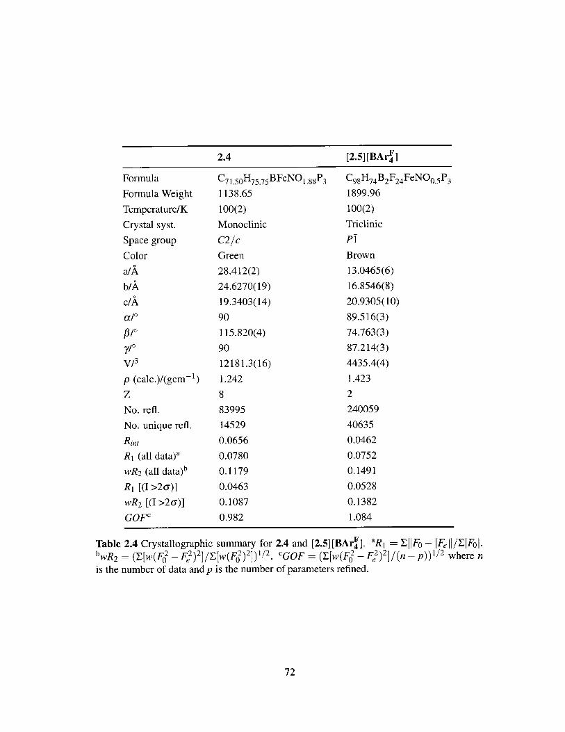
2.4 [2.5] [BAr~]Formula
Formula Weight
Temperature/K
Crystal syst.
Space group
Color
a/A
b/A
c/A
a/0
p/0y/0V/3
p (calc.)/(gcm-1)
zNo. refi.
No. unique refl.
Rint
R1 (all data)a
wR2 (all data)b
R1 [(I >2u)]
wR 2 [(I >2a)]
GOF
C7 1.5 0 H75 .75 BFeNO 1 88P3
1138.65
100(2)
Monoclinic
C2/c
Green
28.412(2)
24.6270(19)
19.3403(14)
90
115.820(4)
90
12181.3(16)
1.242
8
83995
14529
0.0656
0.0780
0.1179
0.0463
0.1087
0.982
C9 8H 74 B 2F 24 FeNO0 .5P 3
1899.96
100(2)
Triclinic
P1
Brown
13.0465(6)
16.8546(8)
20.9305(10)
89.516(3)
74.763(3)
87.214(3)
4435.4(4)
1.423
2
240059
40635
0.0462
0.0752
0.1491
0.0528
0.1382
1.084
Table 2.4 Crystallographic summary for 2.4 and [2.5][BAr]. aR1 = EflFo -IFeH/EiF4LbwR 2 [W(F2 _ F2)2 ] /y w(F) 2 ]) 1/ 2. CGOF (y[w(F2 - F) 21 (n - p))1/ 2 where nis the number of data and p is the number of parameters refined.
72
[2.5][BAr F]42.4

2.8 Bibliography
[1] Luthra, A.; Denisov, I. G.; Sligar, S. G. Arch. Biochem. Biophys. 2011, 507, 26-35.
[2] Kurtz, D. M., Jr. J. Inorg. Biochem. 2006, 100, 679-693.
[3] Britt, R. D.; Campbell, K. A.; Peloquin, J. M.; Gilchrist, M. L.; Aznar, C. P.; Di-cus, M. M.; Robblee, J.; Messinger, J. Biochim. Biophys. Acta 2004, 1655, 158-17 1.
[4] Dey, S.; Das, P. K.; Dey, A. Coord. Chem. Rev. 2013, 257, 42-63.
[5] Lyaskovskyy, V.; de Bruin, B. ACS Catal. 2012, 2, 270-279.
[6] Arifin, K.; Majlan, E. H.; Daud, W. R. W.; Kassim, M. B. Int. J Hydrogen Energy2012, 37, 3066-3087.
[7] Sankar, M.; Dimitratos, N.; Miedziak, P. J.; Wells, P. P.; Kiely, C. J.; Hutchings, G. J.Chem. Soc. Rev. 2012, 41, 8099-8139.
[8] Weller, A. S.; McIndoe, J. S. Eur. J. Inorg. Chem. 2007, 2007, 4411-4423.
[9] Dempsey, J. L.; Esswein, A. J.; Manke, D. R.; Rosenthal, J.; Soper, J. D.; No-cera, D. G. Inorg. Chem. 2005,44, 6879-6892.
[10] Brown, S. D.; Betley, T. A.; Peters, J. C. J. Am. Chem. Soc. 2003, 125, 322-323.
[11] Betley, T. A.; Peters, J. C. Inorg. Chem. 2003, 42, 5074-5084.
[12] Mankad, N. P.; Whited, M. T.; Peters, J. C. Angew. Chem. Int. Ed. 2007, 46, 5768-5771.
[13] Brown, S. D.; Peters, J. C. J. Am. Chem. Soc. 2005, 127, 1913-1923.
[14] Betley, T. A.; Peters, J. C. J. Am. Chem. Soc. 2004, 126, 6252-6254.
[15] Betley, T. A.; Peters, J. C. J. Am. Chem. Soc. 2003, 125, 10782-10783.
[16] Lee, Y.; Mankad, N. P.; Peters, J. C. Nat. Chem. 2010, 2, 558-565.
[17] Mankad, N. P.; Muller, P; Peters, J. C. J. Am. Chem. Soc. 2010, 132, 4083-4085.
[18] MacBeth, C. E.; Harkins, S. B.; Peters, J. C. Can. J. Chem. 2005, 83, 332-340.
[19] Di Vaira, M.; Ghilardi, C. A.; Sacconi, L. Inorg. Chem. 1976, 15, 1555-1561.
[20] Vogel, C.; Heinemann, F. W.; Sutter, J.; Anthon, C.; Meyer, K. Angew. Chem. Int.Ed. 2008, 47, 2681-2684.
[21] Moret, M.-E.; Peters, J. C. J. Am. Chem. Soc. 2011, 133, 18118-18121.
[22] Moret, M.-E.; Peters, J. C. Angew. Chem. Int. Ed. 2011, 50, 2063-2067.
73
[23] Bontemps, S.; Bouhadir, G.; Dyer, P. W.; Miqueu, K.; Bourissou, D. Inorg. Chem.
2007, 46, 5149-5151.
[24] Brown, N. M. D.; Davidson, F; Wilson, J. W. J. Organomet. Chem. 1981, 209, 1-11.
[25] Brown, H. C.; Racherla, U. S. J. Org. Chem. 1986, 51, 427-432.
[26] Welch, G. C.; Holtrichter-Roessmann, T.; Stephan, D. W. Inorg. Chem. 2008, 47,1904-1906.
[27] Jacobsen, H.; Berke, H.; Dbring, S.; Kehr, G.; Erker, G.; Fr6hlich, R.; Meyer, 0.Organometallics 1999, 18, 1724-1735.
[28] Kameo, H.; Hashimoto, Y.; Nakazawa, H. Organometallics 2012, 31, 3155-3162.
[29] Addison, A. W.; Rao, T. N.; Reedijk, J.; van Rijn, J.; Verschoor, G. C. J. Chem. Soc.,Dalton Trans. 1984, 1349-1356.
[30] Sircoglou, M.; Bontemps, S.; Bouhadir, G.; Saffon, N.; Miqueu, K.; Gu, W.;Mercy, M.; Chen, C.-H.; Foxman, B. M.; Maron, L.; Ozerov, 0. V.; Bourissou, D. J.
Am. Chem. Soc. 2008, 130, 16729-16738.
[31] Whited, M. T.; Mankad, N. P.; Lee, Y; Oblad, P. F.; Peters, J. C. Inorg. Chem. 2009,48, 2507-2517.
[32] Verma, A. K.; Nazif, T. N.; Achim, C.; Lee, S. C. J. Am. Chem. Soc. 2000, 122,11013-11014.
[33] Thomas, C. M.; Mankad, N. P.; Peters, J. C. J. Am. Chem. Soc. 2006, 128, 4956-4957.
[34] Mehn, M. P.; Brown, S. D.; Jenkins, D. M.; Peters, J. C.; Que, L., Jr. Inorg. Chem.
2006, 45, 7417-7427.
[35] Lu, C. C.; Saouma, C. T.; Day, M. W.; Peters, J. C. J. Am. Chem. Soc. 2007, 129,4-5.
[36] Nieto, I.; Ding, F.; Bontchev, R. P.; Wang, H.; Smith, J. M. J. Am. Chem. Soc. 2008,130, 2716-2717.
[37] Scepaniak, J. J.; Young, J. A.; Bontchev, R. P.; Smith, J. M. Angew. Chem. Int. Ed.2009, 48, 3158-3160.
[38] Palmer, G. In Physical Methods in Bioinorganic Chemistry; Que, L., Jr., Ed.; Uni-
versity Science Books: Sausalito, CA, pp 121-185.
[39] Moret, M.-E.; MacMillan, S. N.; Peters, J. C. Manuscript in Preparation.
[40] Lee, Y.; Peters, J. C. J. Am. Chem. Soc. 2011, 133, 4438-4446.
[41] Sosinsky, B. A.; Norem, N.; Shong, R. G. Inorg. Chem. 1982, 21, 4229-4233.
74

[42] Pribula, C. D.; Brown, T. L.; Mdnck, E. J Am. Chem. Soc. 1974, 96, 4149-4154.
[43] Clark, M. G.; Cullen, W. R.; Garrod, R. E. B.; Maddock, A. G.; Sams, J. R. Inorg.Chem. 1973, 12, 1045-105 1.
[44] Whited, M. T.; Rivard, E.; Peters, J. C. Chem. Commun. 2006, 1613-1615.
[45] Peters, J. C.; Thomas, J. C. Inorg. Synth. 2004, 34, 8-14.
[46] Sur, S. K. J. Magn. Reson. 1989, 82, 169-173.
[47] Evans, D. F. J. Chem. Soc. 1959, 2003-2005.
[48] Stoll, S.; Schweiger, A. J. Magn. Reson. 2006, 178, 42-55.
[49] Frisch, M. J. et al. Gaussian 09, Revision B.01. Gaussian, Inc., Wallingford, CT,2010.
[50] Zhao, Y.; Truhlar, D. G. Theor Chem. Acc. 2008, 120, 215-241.
[51] Sheldrick, G. M. Acta Cryst. 1990, A46, 467-473.
[52] Sheldrick, G. M. SHELXL-97: Program for Crystal Structure Refinement. Univer-sity of G6ttingen, Gattingen, Germany, 1997.
[53] Muller, P. Crystallogr Rev. 2009, 15, 57-83.
[54] Dolomanov, 0. V.; Bourhis, L. J.; Gildea, R. J.; Howard, J. A. K.; Puschmann, H. J.Appl. Cryst. 2009, 42, 339-341.
[55] van der Sluis, P.; Spek, A. L. Acta Cryst. 1990, A46, 194-201.
[56] Spek, A. L. Acta Cryst. 2009, D65, 148-155.
75

76

Si-H Bond Activation by a Bifunc-
tional Nickel-Borane System
Introduction and Motivation . . . . . . . . . . . . . . . . . . . . . .
Si-H and Ge-H Bond Activation . . . . . . . . . . . . . . . . . . .
[MesDPBPh](H)Ni(SiHPh2): Solution Equilibrium Studies . . . . . .
Hydrosilylation of Benzaldehyde by [MesDPBPh]Ni . . . . . . . . . .
Probing the Mechanism of Benzaldehyde Hydrosilylation . . . . . .
Conclusions and Future Work . . . . . . . . . . . . . . . . . . . . .
Experimental Methods . . . . . . . . . . . . . . . . . . . . . . . . .
3.7.1 General Considerations . . . . . . . . . . . . . . . . . . . . . .
3.7.2 Spectroscopic Measurements . . . . . . . . . . . . . . . . . . .
3.7.3 Preparation of [MesDPBPh](H)NiSiH 2 Ph (3.2) . . . . . . . . . .
3.7.4 Preparation of [MesDPBPh](H)NiSiHPh 2 (3.3) . . . . . . . . . .
3.7.5 Preparation of [MesDPBPh](H)NiGeHPh 2 (3.4) . . . . . . . . .
3.7.6 Preparation of [MeDPBPh]Ni(f 2-benzaldehyde) (3.5) . . . . . .
3.7.7 General Procedure for Catalytic Hydrosilylation Experiments .
3.7.8 General Procedure for Stoichiometric Hydrosilylation Experi-
m ents. . . . . . . . . . . . . . . . . . . . . . . . . . . . . . . .
3.7.9 Mercury Tests for Homogeneity . . . . . . . . . . . . . . . . .
77
3
Contents
3.1
3.2
3.3
3.4
3.5
3.6
3.7
78
80
86
90
92
96
97
97
98
98
99
99
100
100
101
101

3.7.10 Variable Temperature van't Hoff Study of the Equilibrium of 3.1
and 3.3 . . . . . . . . . . . . . . . . . . . . . . . . . . . . . . 101
3.7.11 Variable Temperature van't Hoff Study of the Equilibrium of 3.1
and [MesDPBPh](D)Ni(SiDPh2) . . . - . . . . . . . . . . . . . 102
3.7.12 2D 'H- 1H EXSY study of the equilibrium of 3.1 and 3.3 . . . . 102
3.7.13 X-ray Crystallographic Details . . . . . . . . . . . . . . . . . . 102
3.8 Bibliography . . . . . . . . . . . . . . . . . . . . . . . . . . . . . . . 107
3.1 Introduction and Motivation
The metal-mediated activation of E-H bonds constitutes a fundamental step in a number
of transition metal catalyzed transformations.1 In particular, the activation of Si-H bonds
finds broad application in organic synthesis and is a key component of olefin hydrosilyla-
tion, dehydrogenative silylation and silane dehydrocoupling processes.24 Hydrosilylation
provides a direct and efficient strategy for the functionalization of organic substrates to
produce industrially important organosilicon compounds. 5 In such a process, the oxida-
tive addition of the Si-H bond to the metal center is invoked as one of the first steps of
the catalytic cycle. For example, olefin hydrosilylation may proceed by the Chalk-Harrod
mechanism,6-8 in which Si-H bond activation occurs to form a silyl hydride complex
(Scheme 3.1, left). Subsequent olefin insertion into the M-H (Chalk-Harrod) or M-Si
bond (modified Chalk-Harrod),7' 9'1 0 followed by reductive elimination yields the final re-
action product. In the Glaser-Tilley mechanism, 11-14 a silylene hydride complex is formed
by double Si-H bond activation (Scheme 3.1, right). Direct addition of the olefin to the
Si-H bond of the silylene fragment and metal-to-silicon hydride transfer forms a silyl hy-
dride species. Finally, reductive elimination yields the organic product. The Chalk-Harrod
and modified Chalk-Harrod mechanisms are invoked for many transition-metal catalysts;
the Glaser-Tilley mechanism, however, is specific to ruthenium-mediated hydrosilylation
processes.
Although Si-H bond activation is well known for metals of the nickel triad, 15-29 there
78

[ R3Si-HEtSiR3
[M]H
[M] RSiH3
EtSiH 2R
[M] SiRH
SIR3 HX__/SiR
IMIS
[M]% SOR [M]% //HR [M] SR
Chalk-Harrod/Modified Chalk-Harrod Glaser-Tilley
.1 (left) Chalk-Harrod and modified Chalk-Harrod mechanisms and (right)
ey mechanism for the hydrosilylation of olefins.
is far less knowledge about nickel silyl and nickel silyl hydride species in comparison
to their platinum counterparts due to their instability and high reactivity. 15 The use of
bulky or chelating ligands has allowed for the isolation of a number of mononuclear nickel
silyl 16,30-33 and nickel silane complexes. 30,34-36 However, well-characterized mononuclear
nickel silyl hydride complexes, which are the expected products of Si-H bond oxidation
addition at nickel, are rare.3 5 ,37' 38 Fischer reported the isolation and crystal structure of the
unusual nickel silyl hydride species Ni(AlCp*) 3 (H)(SiEt3 ) (Cp* = 7 5-C5Me5 ) supported by
pentamethylcyclopentadienyl aluminum(I) ligands (Figure 3.1, left). 3 8 Subsequently, Ra-
dius employed the N-heterocyclic carbene (NHC) ligand 'PrIm ('PrIm = 1,3-di-isopropyl-
imidazolin-2-ylidene) to stabilize four-coordinate nickel silyl hydride complexes of the
form ('PrIm)2 Ni(H)(SiRPh 2 ) (R = Me or Ph, Figure 3.1, right). 37
AlCp*HSAEt %p HSiRPh2 'Prims ,,,H
Ni(AICp*)3 'N H -N! AIC Ni 2(iPrIm) 4(cod) NiA / A Orim SiRPh 2Et 3Si AICp*
R=Me orPh
Figure 3.1 Structurally characterized nickel silyl hydride complexes reported by (left)
Fischer 38 and (right) Radius 37 (Cp* = 75-C5Me 5; 'PrIm = 1,3-di-isopropyl-imidazolin-2-ylidene).
The Peters group recently reported the preparation of a low-valent bis(phosphine)borane
nickel complex, [MesDPBPh]Ni (3.1), which can reversibly cleave H 2 to generate the boro-
hydridohydride species, [MesDPBPh](H)Ni(H), as shown in Scheme 3.2 ([MesDPBPh] _
MesB(o-PPh 2 C 6 H4 )2). 39 Preliminary results indicate that 3.1 is a competent olefin hy-
drogenation catalyst. Intrigued by the observed bifunctional activity of [MesDPBPh], the
79
Scheme 3Glaser-Till

work in this chapter seeks to access traditionally reactive nickel silyl hydride species by
exploiting the stabilizing Ni-+B interaction of 3.1. Herein is described the preparation of
well-characterized nickel borohydridosilyl complexes derived from the oxidative addition
of silane substrates to a nickel(0) center and the mechanism of benzaldehyde hydrosilyla-
tion by 3.1.
;?PPh21Y! \iH 2 B\
PPh2H2
Ph2(3.1)
R = Ph, t-Bu
Scheme 3.2 Reversible H2 activation by the bis(phosphine)borane nickel complex 3.1.
Complex 3.1 is also a competent hydrogenation catalyst.
3.2 Si-H and Ge-H Bond Activation
The previously reported nickel bis(phosphine)borane complex 3.1, is prepared by compro-
portionation of 0.5 equiv of Ni(cod) 2 and 0.5 equiv of NiCl 2 in the presence of [MesDPBPh],
followed by reduction with an excess of Na/Hg in THF (Scheme 3.3).39 This species is a
dark brown powder, with a singlet in the 3 1P { 'H} NMR spectrum at 25.6 ppm. The IH
NMR spectrum features three well-separated, diagnostic peaks at 5.63, 1.82 and 1.63 ppm,
corresponding to the mesityl aryl protons, mesityl p-methyl group and the mesityl o-methyl
groups, respectively. Complex 3.1 does not react with tertiary aryl or alkylsilanes, such as
HSiPh3 , HSiEt3 and HSi(OEt)3 ; heating C6 H 6 solutions of 3.1 and a tertiary silane to 50
'C for 6 h does not promote any reaction. Heating C6H 6 solutions of 3.1 and an excess
of tertiary silane (i.e., more than 2 equiv) to 50 'C forms a complex mixture of products.
Free mesitylene is a major product of these reactions and forms as a result of B-C i
bond cleavage. Despite these complications, 3.1 does activate Si-H bonds of primary and
secondary arylsilanes at room temperature. 40
Treatment of a C6 H6 solution 3.1 with 1 equiv of H 3 SiPh resulted in an immediate
80
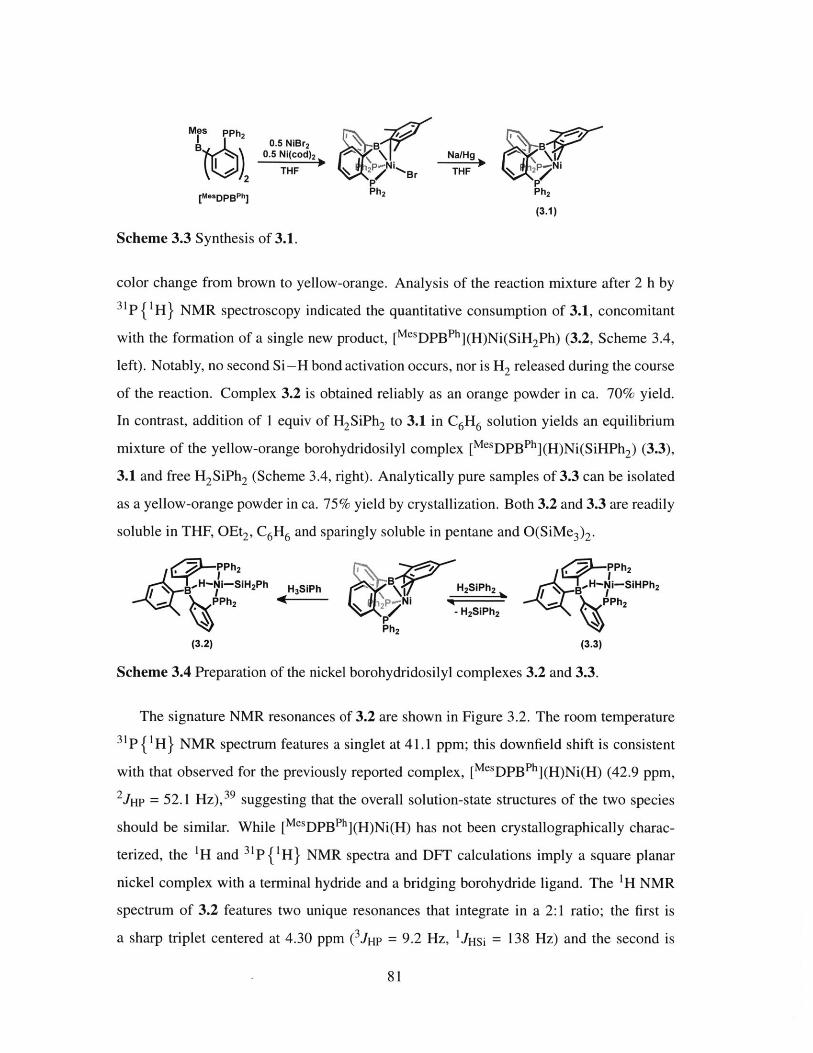
0.5 N od)2 \
Ph 2
Na/HgTHF &2t~PN
Ph 2
(3.1)
Scheme 3.3 Synthesis of 3.1.
color change from brown to yellow-orange. Analysis of the reaction mixture after 2 h by
31P {'H} NMR spectroscopy indicated the quantitative consumption of 3.1, concomitant
with the formation of a single new product, [MesDPBPh](H)Ni(SiH 2Ph) (3.2, Scheme 3.4,
left). Notably, no second Si-H bond activation occurs, nor is H2 released during the course
of the reaction. Complex 3.2 is obtained reliably as an orange powder in ca. 70% yield.
In contrast, addition of 1 equiv of H2SiPh2 to 3.1 in C6H6 solution yields an equilibrium
mixture of the yellow-orange borohydridosilyl complex [MesDPBPh](H)Ni(SiHPh 2) (3.3),
3.1 and free H2SiPh2 (Scheme 3.4, right). Analytically pure samples of 3.3 can be isolated
as a yellow-orange powder in ca. 75% yield by crystallization. Both 3.2 and 3.3 are readily
soluble in THF, OEt2, C6H6 and sparingly soluble in pentane and O(SiMe 3)2.
7fo P(h2 PPh 2
Ni-SIH 2Ph SPh H2SiPh2 B -S IHPh2
.,- PPh2 p-N qR ... PPh2
4 *j~ <B~ H3SiPPh 2 -H2SiPh2
(3.2) (3.3)
Scheme 3.4 Preparation of the nickel borohydridosilyl complexes 3.2 and 3.3.
The signature NMR resonances of 3.2 are shown in Figure 3.2. The room temperature
31P { 'H} NMR spectrum features a singlet at 41.1 ppm; this downfield shift is consistent
with that observed for the previously reported complex, [MesDPBPh](H)Ni(H) (42.9 ppm,
2jHP = 52.1 Hz),3 9 suggesting that the overall solution-state structures of the two species
should be similar. While [MesDPBPh](H)Ni(H) has not been crystallographically charac-
terized, the 'H and 31p f 'H} NMR spectra and DFT calculations imply a square planar
nickel complex with a terminal hydride and a bridging borohydride ligand. The 'H NMR
spectrum of 3.2 features two unique resonances that integrate in a 2:1 ratio; the first is
a sharp triplet centered at 4.30 ppm ( 3jHP = 9.2 Hz, 1JHSi = 138 Hz) and the second is
81
Mes PPh 2IsP
[MesDPBPh]

a broad singlet at -2.47 ppm. The triplet arises from the coupling of the proton to two
equivalent phosphorus nuclei. The presence of silicon satellites and the distinct chemical
shift indicates that this resonance corresponds to the Si-H protons. The broad resonance
at -2.47 ppm is assigned to the bridging borohydride ligand. Although one might predict
coupling of this proton to the two equivalent phosphorus nuclei, the expected line shape is
broadened due to quadrupolar relaxation of the attached 11B nucleus. The "1B { 1H} NMR
resonance of 3.2 is shifted upfield relative to 3.1 (-2.2 ppm vs 21.6 ppm), consistent with
an increase in electron density at boron. The 2 9 Si {1H} NMR spectrum features a triplet
centered at -17.0 ppm (2 jSip = 38.7 Hz); the small 2JSip value suggests a cis-arrangement
of the silicon and phosphorus atoms. The solid-state (ATR, thin film) IR spectrum contains
an Si-H stretch at 2060 cm- 1 . Taken together, these spectral features indicate that the ge-
ometry around the nickel center is as drawn in Scheme 3.4: a distorted square planar center
with two trans-phosphine donors, a terminal silyl group and a hydride ligand bridging the
nickel and boron centers.
(a)
- JHP = 9.2 Hz
JHSi = 138 Hz
.8 4.7 4.6 4.5 4.4 4.3 4.2 4.1 4.0 3.9 3 8 -2.0 -2.2 -2.3 -2.4 -2.5 -2.6 -2.7 -2.8 -2.9PPM
(b) (c) (d) 2 sP=38.7 Hz
46 44 42 40 3'8 36 34 100 50 0 -50 -100 -15 -16 -17 -18 -19
Figure 3.2 Signature resonances in the (a) 1H, (b) 3 1p{'H}, (c) 1 B{'H}, and (d)29 5i {' H} NMR spectra of 3.2.
The NMR resonances of 3.3 are similar to those of 3.2 and a summary of the unique
resonances is given in Table 3.1. The room temperature 1H NMR spectrum of 3.3 features
two signature resonances that integrate in a 1:1 ratio. The sharp triplet at 5.01 ppm (3jHP
82

= 14.7 Hz, 1 JHSi = 88 Hz) corresponds to the Si-H proton, while a broad resonance at
-2.61 ppm is assigned as the bridging borohydride ligand. The 3 1 P{1H} and 11B {1H}
NMR resonances of 40.9 and -1.7 ppm, respectively, are analogous to those observed
for 3.2. The 29si { 1H} NMR spectrum shows a triplet centered at 3.1 ppm with a small
2JSip coupling constant (37.9 Hz), again suggesting a cis-arrangement of the silicon and
phosphorus atoms. The solid-state (ATR, thin film) IR spectrum contains a Si-H stretch at
2058 cm- 1 .
3.2 3.3
4.30 5.011H 3 (m) (t, 3 JHP = 9.2 Hz, 1JHSi = 138 Hz, 2H) (t, 3 JHP = 14.7 Hz, 1 JHSi = 88 Hz, 1H)
-2.47 (s, 1H) -2.61 (s, 1H)31P (m) 41.1 (s) 40.9 (s)
11B 3 (m) -2.2 (br, s) -1.7 (br, s)2 9 Si 3 (M) -17.0 (t, 2 JSip = 38.7 Hz) 3.1 (t, 2 JSip = 37.9 Hz)
Table 3.1 Comparison of the signature NMR resonances of 3.2 and 3.3.
The assignment of 3.2 and 3.3 was confirmed by X-ray crystallographic analysis. Both
complexes crystallize in the triclinic space group P1 with one and two molecules in the
asymmetric unit, respectively. As predicted, the nickel centers are in distorted square pla-
nar geometries, with two trans-phosphine ligands, a terminal silyl group and a bridging
borohydride ligand (Figure 3.3). Selected bond lengths and angles of 3.2 and 3.3 are sum-
marized in Table 3.2. The nickel, phosphorus and silicon atoms are coplanar and the angles
about nickel deviate slightly from the value expected for a square plane. This distortion
is also reflected in the deviation of the Pl-Ni-P2 and Si-Ni-HOO angles from ideal
linearity. The average Ni-P distances (3.2: 2.1495(4) A; 3.3: 2.1713(7) and 2.1578(8)
A) are within the range found for other trans-phosphine nickel complexes (2.10 - 2.32 A).
There are very few structurally characterized bridging triarylborohydride transition metal
complexes; however, the B-H distances of 3.2 (1.31(2)0) and 3.3 (1.26(3) and 1.27(3)')
are consistent with those in the literature (1.25 - 1.48 A). 41 - 5 Although these previously
reported species exhibit a wide range of B-H-M angles, the majority lie between ca. 100
and 120'. The B-H-Ni angles of 3.2 (114.27') and 3.3 (118.72 and 120.20') also fall
83

within that range. The Ni-H distances (3.2: 1.59(2) A; 3.3: 1.64(3) and 1.63(3) A) are
shorter than the M-H distances observed in bridging triarylborohydride transition-metal
complexes (avg 2.02 A). They are, however, similar to the average Ni-H distance of other
terminal bis(phosphine) nickel(II) hydride species (1.52 A).,- The Ni-Si distances
(3.2: 2.2379(4) A; 3.3: 2.24669(7) and 2.2491(7) A) are comparable to other mononuclear
nickel complexes containing a monodentate silyl fragment (2.14 - 2.37 A).3 -32,37 5 -0
P1H102 P11
H100 iSNi S H100 Nil
B Bl 7i 1SH101
P2 P12 H102
Figure 3.3 Solid-state structures of 3.2 (left) and 3.3 (right). Thermal ellipsoids are drawnat 40% probability. Hydrogen atoms bound to carbon and solvent molecules are omittedfor clarity. For 3.3, only one molecule of the asymmetric unit is shown.
Secondary arylgermanes are also activated by 3.1; treatment of 3.1 with 1 equiv of
H2GePh2 generates yellow [MesDPBPh](H)Ni(GeHPh 2) (3.4) in ca. 75% yield (Scheme 3.5).
As with 3.2 and 3.3, the room temperature 3 1P { H} NMR resonance is shifted downfield
from that of 3.1 (40.4 ppm) and the 11B { 1H} NMR resonance of -0.8 ppm is indicative of
increased electron density at boron. The sharp triplet at 4.64 ppm (3 JHP = 12.5 Hz) and the
broad resonance at -4.28 ppm in the 1H NMR spectrum are assigned to the Ge-H pro-
ton and bridging borohydride, respectively. Crystals for X-ray spectroscopic analysis were
obtained by vapor diffusion of O(SiMe3)2 into a concentrated toluene solution of 3.4 and
the structure is shown in Figure 3.4. Unfortunately, the crystals selected for data collection
were not single and the solution to the structure of 3.4 poses some problems. Initial refine-
ment suggests that the preferred solution is the triclinic space group P!, with three indepen-
dent molecules in the asymmetric unit. This solution furnishes two well-behaved molecules
84

3.2 3.3
Molecule 1 Molecule 2
Ni-Si 2.2379(4) 2.2466(7) 2.2491(7)
Ni-P (avg) 2.1495(4) 2.1713(7) 2.1578(8)
Ni-B 2.440(2) 2.498(3) 2.514(3)
Ni-HOG 1.59(2) 1.64(3) 1.63(3)
B-H100 1.31(2) 1.26(3) 1.27(3)
P1-Ni-Si 89.83(2) 98.91(3) 100.08(3)
P1-Ni-H100 87.2(7) 82.7(9) 84.8(9)
P2-Ni-Si 98.10(2) 90.34(3) 90.95(3)
P1-Ni-P2 171.81(2) 169.56(3) 168.63(3)
Si-Ni-H100 168.3(7) 167.2(9) 160.0(9)
B-H100-Ni 114.27 118.72 120.20
Table 3.2 Selected bond lengths (A) and angles (0) for 3.2 and 3.3.
and one highly disordered molecule with a number of non-positive definite atoms. The
structure was revisited and refined using a smaller unit cell; this method provided a solu-
tion in the same space group (PI) with one independent molecule in the asymmetric unit.
Although this solution is more appropriate than the first (R1 ~ 9% vs 16%), the data is still
of poor quality and only sufficient to provide a picture of the connectivity of the molecule.
The geometry of 3.4 is distorted square planar with two trans-disposed phosphines and a
terminal germyl ligand. The bridging borohydride ligand was not located in the difference
map. The P-Ni-Ge angles are asymmetric; the P1-Ni-Ge angle is ca. 90.8' and the
P2-Ni-Ge angle is ca. 98.0'. The Ni-Ge distance is ca. 2.3 A and the average Ni-P
distance is ca. 2.2 A. These distances are expected given the metrical parameters of 3.2 and
3.3.
, 5 PPh2
Ph 2GeH 2 BH iGeHPh 2 Yellow powderp2 Ni Ph2 75% yield
&Z 214 CGH 6 h
Ph 2(3.4)
Scheme 3.5 Treatment of 3.1 with 1 equiv of H2GePh2 yields the borohydridogermyl com-plex 3.4.
85
3.33.2

Selected Bond Lengths (A) and Angles (0)Ni-Ge = 2.3
Ni Ni-P (avg) = 2.2NI-B = 2.5
P1-NI-Go = 90.8
Pi H900 P2-Ni-Ge = 98.0
Figure 3.4 Solid-state structure of 3.4. Thermal ellipsoids are drawn at 40% probabil-ity. Hydrogen atoms bound to carbon are omitted for clarity. See the main text for moreinformation about the selected bond lengths and angles.
Because of the greater interest in silane chemistry in the literature, the chemistry of 3.4
was not pursued. Other E-H bonds, such as O-H, N-H and P-H, are also of interest.
However, treatment of THF solutions of 3.1 with these types of E-H substrates did not
result in bond activation. For example, heating a THF solution of 3.1 with 1 equiv of
HOPh to 70 'C for one week yielded no reaction; the addition of excess HOPh did not
promote any reaction. Treatment of 3.1 with 1 equiv of HPPh2 did result in the formation
of a new product, but it was identified as the phosphine adduct, [MesDPBPh]Ni(PHPh 2), not
the desired P-H activated species. Complex 3.1 does activate S-H bonds and these results
will be presented in Chapter 4.
3.3 [MesDPB Ph](H)Ni(SiHPh 2): Solution Equilibrium Stud-
ies
The well-defined solution equilibrium of 3.1 and 3.3 provided the opportunity to study both
the thermodynamics and kinetics of Si-H bond activation by 3.1. At 27 'C, dissolution of
pure 3.3 in C6D6 gives an equilibrium mixture of 3.1, 3.3 and H 2SiPh2, corresponding to a
Keq of ca. 960 M-1. A van't Hoff analysis over a 50 K range, shown in Figure 3.5, yielded
thermal parameters of AH = -12 ± 1 kcal/mol and AS = -27 ± 3 eu. Repeating the
experiment with D2SiPh2 over a 70 K range yielded thermal parameters of AH = -20 +
1 kcal/mol and AS = -47 ± 3 eu, with an inverse equilibrium isotope effect of EIE328 =
86

0.18.61 A representative 1H NMR spectrum of this solution equilibrium taken at 65 'C in
C6D6 is shown in Figure 3.6.
10 10 Protiosilaneo Deuterosilane
y =10.132x - 23.763
R2=0.9
8
y = 6.276x - 13.707
R2= 0.9994
2.7 2.8 2.9 3 3.1 3.2 3.3 3.4
1000/T (K-1)
Figure 3.5 Van't Hoff plots derived from variable temperature 'H NMR spectra of thesolution equilibrium of 3.1, 3.3 and free H2SiPh or D2 SiPh2 . The equilibrium involvingH2 SiPh2 was monitored from 328 to 368 K, while the equilibrium involving D2SiPh2 wasmonitored from 298 to 358 K.
The chemical exchange kinetics of the Si-H bond activation process defined in Scheme
3.4 were studied by 2D exchange spectroscopy (EXSY) NMR experiments. 62,63 This well-
established technique has been used to measure quantitative kinetic data of chemical ex-
change processes in organometallic complexes. In practice, the exchanging resonances
must be resolved, meaning that the exchange process is slow on the NMR time scale. Too
slow of an exchange process, however, can lead to a decrease in the cross-peak signal due to
relaxation during the mixing time of the experiment. Thus, exchange processes with rates
of ca. 102 to 10-2 s- 1 can be appropriately investigated using the EXSY NMR technique.
1H-1H EXSY spectra were recorded in C6D6 over a range of temperatures with mixing
times (Tm) of 0 and 700 ms. A representative EXSY spectrum recorded at 75 'C is shown in
Figure 3.7. The Mes-H aryl resonances of 3.1 and 3.3 are well separated and so these were
the peaks chosen for analysis. Figure 3.8 shows EXSY spectra recorded at 75 'C, expanded
to focus on the Mes-H resonances of interest (left: Tm = 0 ms; right: Tm =700 ms). The peak
87

(3.3)(CH 3)
(3.3) (3.1)(Mes-H) (3.1) (CH 3)
(Mes-H) (Si-H)
6.4 6.2 6.0 5.8 5.6 5.4 5.2 5.0 4.8 2.2 2.0 1.8 1.6
Chemical Shift
Figure 3.6 Representative 1H NMR spectrum of the solution equilibrium of 3.1, 3.3 andfree H2SiPh2 collected at 65 'C in C6D6 . Free H2SiPh2 is indicated by the * symbol.
volumes of the diagonal and off-diagonal signals were obtained by integration and then
processed with EXSYCalc 64 to determine the forward (k') and reverse (k' 1) magnetization
rate constants. These rates were then converted to chemical exchange rate constants, k, and
k_1, by taking into account the concentration of H2SiPh2 using the following equations:
k' 1 kik1 = -k_1 =k' 1 Kap =[H2SiPh2 app k-_
where the concentration of H2SiPh2 is assumed to be equal to the concentration of 3.1 in
solution. The results of the analysis are shown in Table 3.3. The Kapp values obtained
from this technique are in good agreement with the Keq values obtained by the variable
temperature van't Hoff analysis. Eyring analysis of the data obtained from the EXSY
experiments gave AH* = 3.9 ± 1 kcal/mol and AS* = -39 ± 3 eu for the forward reaction
and AH* = 17 ± 1 kcal/mol and AS* = -9.6 ± 3 eu for the reverse process. Unfortunately,
the chemical exchange process for the system with D2SiPh2 is too slow on the NMR time
scale and study by the EXSY technique is not suitable.
88

g * 1.5
*2.0
2.5
3.0
3.5E4.0 C.
(3.1) (Mes-H)4. 4, .;.4515.0 u)
je E5.5
6.0
......... 6.5
alT 7.0
% (3.3) (Mes-H) 7.5
* S 8.0
8.5
8.0 7.5 7.0 6.5 6.0 5.5 5.0 4.5 4.0 3.5 3.0 2.5 2.0 1.5
Chemical Shift (ppm)
Figure 3.7 Representative 1H-1H EXSY NMR spectrum of the solution equilibrium of 3.1,3.3 and free H2SiPh2 (75 0C, C6D6 , Tm = 700 ms).
5.5 5.5
5.6 5.6
5.7 5.7(3.1) (Mes- H) (3.1) (Mes-H 5
5.8 5.8E E
5.9 5.9 .
6.0 6.0
6.1 .1
(3.3) (Mes--) 6.2 0 (3.3) (Mes-H) .2
6.3 6.3
6.4 6.4
65 6.5
6.40 6.30 6.20 6.10 6.00 5.90 5.80 5.70 5.60 5.50 5.40 6.40 6.30 6.20 6.10 6.00 5.90 580 5.70 5.60 5.50 5.40
Chemical Shift (ppm) Chemical Shift (ppm)
Figure 3.8 Expansion of the 1H- 1H EXSY NMR spectrum of the solution equilibrium of3.1, 3.3 and free H2SiPh2 (75 0C, C6D6). (left) Tm = 0 ms. (right) Tm = 700 ms.
89

Temperature (K) [H 2SiPh2] = [3.1] (M) k, (M-1s-1) k_ 1 (s-') Kapp (M- 1) Keq
327 1.29 x 10- 2 43 0.16 270 230337 1.45 x 10- 2 51 0.36 140 139347 1.76 x 10- 2 67 0.79 85 81357 1.99 x 10- 2 73 1.4 50 49
Table 3.3 Rate constants for the solution equilibrium of 3.1, 3.3 and free H2SiPh2 as deter-mined by 2D EXSY spectroscopy. Keq values determined by the variable temperature van'tHoff analysis are included for comparison.
3.4 Hydrosilylation of Benzaldehyde by [MesDPBPh] N
In an effort to incorporate the Si-H bond activation process into a useful catalytic cy-
cle, the hydrosilylation of unsaturated substrates was examined. Attempts to hydrosilylate
olefins and alkynes with 5 mol % of 3.1 at room temperature resulted in isomerization or
no reaction, respectively; heating these reaction mixtures to 40 'C led to decomposition of
3.1 by B-Car1 bond cleavage. Gratifyingly, the hydrosilylation of benzaldehyde with 5
mol % of 3.1 was accomplished in 99% yield within 6 h (Table 3.4, entry 1). Catalyst 3.1 is
tolerant of a range of para-substituents, including electron-donating, electron-withdrawing
and basic groups (Table 3.4). In general, the rate of reaction increases with more electron-
donating substituents in the para position. This is in contrast to the iron pyridinediimine
system (PDI) reported by Chirik.65 Doubling the concentration of 3.1 doubled the reaction
rate, suggesting that the transformation is first order in 3.1. The rate of the reaction did
not change with varying ratios of H2SiPh2 or aldehyde, indicating that the reaction is zero
order in both H2SiPh2 and aldehyde substrate (Figure 3.9).
90

0%% H
RHRQA
5 mol % 3.1H2SiPh 2, Cr6D6
OSiHPh2
H
Entry" Substrate Conversion; Time Chemical Yieldb
1 R=H >98%; 5.9 h 99%
2 R=Me >98%; 2.5 h 97%
3 R = OMe >98%; 2.7 h 98%
4 R = NMe2 >98%; 44 m 98%
5 R = CF3 >98%; 4.6 d 92%
a 1 mmol substrate, 1 mmol H2SiPh2, 5 mol % 3.1, 500 yL C6D6- b Determined by NMRintegration against an internal standard.
Table 3.4 Summary of results of catalytic hydrosilylation of para-substituted benzaldchy-des by 3.1.
0 5000 10000 15000 20000Time (sec)
25000 30000 35000
Figure 3.9 Plot of aldehyde concentration versus time for the hydrosilylation of p-dimethylaminobenzaldehyde by 1.25, 2.5 and 5 mol % of 3.1.
In addition to studying the individual rates of hydrosilylation, competition experiments
were carried out to assess substituent effects. For each experiment, the hydrosilylation of
two equimolar substrates was monitored (1 equiv benzaldehyde A: 1 equiv benzaldehyde
B: 1 equiv H2SiPh2) in the presence of 5 mol % of 3.1. The Hammett correlation of the rel-
91
A 1.25 mol%o 2.5 mol%O 5mol%
0.14
0.12
0.1
75E 0.08
.c 0.06
'a0.04
0.02
0

ative rates of hydrosilylation is illustrated in Figure 3.10 and shows that electron-donating
substituents in the para position accelerate the rate of hydrosilylation. The reaction solution
remained transparent during the course of catalysis and mercury has no effect on the rate
or products of the reaction, supporting a homogeneous catalytic system.
1.2 p -1.4S0R2 .982
1-
0.8
0.6
0.4 Ome
0.2
0 Meo H
-0.2
-0.4 CF3
-0.6 1 . I I . I-0.8 -0.6 -0.4 -0.2 0 0.2 0.4
Hammett Constant (a)
Figure 3.10 Hammett correlation diagram for the relative rates of hydrosilylation of para-substituted benzaldehydes by 3.1.
3.5 Probing the Mechanism of Benzaldehyde Hydrosilyla-
tion
Ty'pically, the transition metal-catalyzed reduction of carbonyl functionalities is mediated
by rhodium, platinum and other precious metals. In recent years, however, there have
been numerous efforts to incorporate more environmentally benign and less expensive first-
row metals, such as titanium, 6 - 9 iron,70- 74 nickel 52,75-77 and copper. 78~0 Mechanistic
proposals for these metal catalysts generally invoke a hydride mechanism in which a metal
hydride species is generated, followed by carbonyl insertion into the M-H bond to give an
alkoxide complex.
Three possible mechanisms for the hydrosilylation of benzaldehydes catalyzed by 3.1
are outlined in Scheme 3.6. In each mechanism, H2SiPh2 adds to 3.1 to generate 3.3.
92

Benzaldehyde can insert into the Ni-H bond to generate a nickel alkoxide intermediate
[A], which can then undergo reductive elimination of the organic product to regenerate 3.1
(Scheme 3.6, left). Alternatively, in an Ojima-type mechanism, 8 1 benzaldehyde can insert
into the Ni-Si bond to generate a nickel borohydridosiloxyalkyl intermediate [B], followed
by reductive elimination of the hydrosilylated product (Scheme 3.6, right). Finally, in a
Zheng-Chan-type mechanism, benzaldehyde can insert into the Si-H bond to generate the
intermediate species [C], which can then lose the organic product via reductive elimination
to close the catalytic cycle (Scheme 3.6, right). 82
0
Ni-0 Ni H PhH Ph
OSi
PhA H H2SiPh2051 ' H2SiPh2 H Ni
Ph' H Ni 2HHHNPjH
H-Ni-SB Ph BH-Ni-Si
Ph. -Ni-Si H [C] H-Ni H PhPhH Ph H[A]
Scheme 3.6 Possible mechanisms for the hydrosilylation of benzaldehyde by 3.1.
To better understand the hydrosilylation process, stoichiometric reactions were carried
out using [a- 13 C]-benzaldehyde. Treatment of a toluene-d 8 solution of 3.1 with a stoi-
chiometric amount of [a- 13 C]-benzaldehyde yielded a red solution with a singlet in the
3 1 P 1H} NMR spectrum at 38.0 ppm. In the 13 C {1H} NMR spectrum, there is a broad
resonance at 84.1 ppm (free aldehyde = 193 ppm) that is coupled to a broad 1 H NMR res-
onance at 5.81 ppm, as determined by a 2D HSQC NMR experiment. Upon cooling to
-60 'C, these features sharpen and shift, with a 1H NMR resonance at 5.99 ppm that is
coupled to a 13 C { 1 H} NMR resonance at 91.3 ppm (HSQC). In the proton-coupled 13 C
NMR spectrum at this temperature, the peak at 91.3 ppm splits into a doublet with JCH =
174 Hz (free aldehyde, JCH = 174 Hz). The upfield shifts of the 1H and 13C NMR reso-
nances are indicative of substantial d-* 7r* back donation, 83 consistent with other nickel
72 -aldehyde species reported in the literature. 84-86 Based on these observations, this new
93

species is assigned as [MesDPBPh]Ni(12-benzaldehyde) (3.5, Scheme 3.7, left).
Complex 3.5 was isolated as a red microcrystalline material in ca. 80% yield and the
identity of 3.5 confirmed by X-ray crystallographic analysis (Figure 3.7, right). Complex
3.5 crystallizes in the monoclinic space group P21/n with one molecule in the asymmetric
unit. As predicted by the solution NMR data, the nickel atom is formally three-coordinate
with benzaldehyde bound in an 7l 2 fashion. The C-O linkage lies in the trigonal coordi-
nation plane; the sum of the angles around the benzaldehyde carbon is 353.5(8)* and the
phenyl ring and C=O bond are coplanar. The C-O bond length of 1.312(2) A is slightly
shorter than those reported for related Ni(i 2-CO) complexes (1.32 - 1.34 A), for exam-
ple, 1.345(2) A in Ni(7 2-HPhCO)(dippe) (dippe = 1,2- bis(diisopropylphosphino)ethane),
reported by Cimpora. 84
(3.1)
H
Pi H46Ni C46
2 0H
h- ,: iPhPh
Ph' "Ph
(3.5)
Scheme 3.7 (left) Preparation of 3.5. (right) Solid-state structure of 3.5. Thermal el-lipsoids are drawn at 40% probability. Hydrogen atoms, except for H46, and solventmolecules are omitted for clarity. Selected bond lengths (A) and angles (0) for 3.5: Ni-P1 =2.1376(2); Ni-P2 = 2.2198(2); Ni-O = 1.8749(6); Ni-C46 = 1.9906(8); C-O = 1.314(1);P1 -Ni-P2 = 111.08(1); sum of the angles about C46 = 353.5(8).
Upon treatment of an equimolar solution of 3.1 and [a- 13C]-benzaldehyde with stoi-
chiometric H2SiPh2, a new intermediate species forms. This species has a half-life of ca.
15 minutes at room temperature. The 13C { 1H} NMR spectrum of the solution features two
singlets at 76.9 ppm and 66.4 ppm, corresponding to the intermediate and the final hydrosi-
lylated product, respectively. In the proton-coupled 13C NMR spectrum, the peak at 76.9
ppm splits into a doublet (JCH = 159 Hz) and the peak at 66.4 ppm splits into a triplet (JCH
94

= 142 Hz). Over the course of the reaction, the resonance associated with the intermediate
decays, concomitant with growth of the product peak. The intermediate resonance is cou-
pled to a 1 H NMR signal at 5.18 ppm, as determined by 2D HSQC NMR. In addition, there
is a new hydride resonance at -11.4 ppm in the 1H NMR spectrum. The 31 p{ 1H } NMR
spectrum exhibits a singlet at 38.0 ppm, corresponding to 3.5 and two doublets centered at
34.9 (2Jpp = 210.6 Hz) and 28.0 ppm (2Jpp = 210.6 Hz), corresponding to the intermediate
species. These three sets of peaks decay over the course of the reaction and at the end of
the reaction the only 3 1 P{lH} NMR resonance is that of 3.1. No other 3 1pf'H} NMR
resonances are observed during the reaction, indicating that [MesDPBPh] remains bound to
nickel throughout. No 13 C_ 3 1P coupling was resolved, even upon cooling to -80 'C. Re-
peating the reaction under catalytic conditions (5 mol % of 3.1) yielded spectra with signals
analogous to those described above (Figure 3.11). Under these conditions, a small amount
of an off-path, unidentified nickel complex is formed and best observed by 3 1P {1 H} NMR
spectroscopy. In addition to the peaks corresponding to 3.5 and the intermediate species,
there is another set of doublets centered at 12.7 (2Jpp = 294.8 Hz) and 8.3 ppm (2Jpp =
294.8 Hz); this species does not decay over the course of the reaction and accounts for 6%
of the total phosphorus content in solution, as determined by integration at the end of the
reaction.
In evaluating the mechanisms and intermediates outlined in Scheme 3.6, the following
considerations are of particular importance:
1. A hydride resonance is observed in the 'H NMR spectrum, ruling out [A] as the
intermediate species.
2. In the proton-coupled 13 C NMR spectrum, the peak corresponding to the intermedi-
ate species splits into a doublet, indicating that only one proton is directly attached to
the 13 C-labeled carbon atom, thereby ruling out both [A] and [C] as the intermediate
species.
3. Siloxyalkyl complexes of various transition metals have been reported in the litera-
ture 87-92 and the 13 C {1H} NMR shifts of the metal-bound carbon atoms range from
69 ppm to 76 ppm; the 13 C {'H} NMR shift of the intermediate species for this
95

Free adehyde
200 180 100 80 60
Hydrosilylatedproduct
Freedaydd
200 180 100 80 60
(3.5)Intermediate
Off-path species
0 60 40 20 0 -20
Chemical Shift (ppm)
Figure 3.11 Representative spectra for hydrosilylation under catalytic conditions. (top)Proton-coupled 13C NMR spectrum recorded at -60 'C after thawing the reaction mixture.(middle) Proton-coupled 13C NMR spectrum recorded at -60 'C after removing from the
probe and shaking at room temperature for 5 min. (bottom) 31p{ 1H} NMR spectrumrecorded at room temperature 5 min after silane addition.
system (76.9 ppm) is slightly downfield of this range.
Taken together, the data is most consistent with the hydrosilylation reaction proceeding by
an Ojima-type mechanism and the intermediate species observed being a nickel borohydri-
dosiloxyalkyl complex (Scheme 3.6, right, [B]).
3.6 Conclusions and Future Work
In this chapter, the facile E-H (E = Si, Ge) bond activation by a nickel bis(phosphine)bor-
ane complex was described. The crystal structures of the resulting nickel borohydrido-E
complexes were discussed. Complex [MesDPBPh](H)Ni(SiHPh 2) is in solution equilibrium
with [MesDPBPh]Ni and free H2SiPh2 and the process was characterized by 2D EXSY
NMR experiments. The system displays an inverse equilibrium isotope effect (EIE328 =
96
L -- . --- _ W-WIF
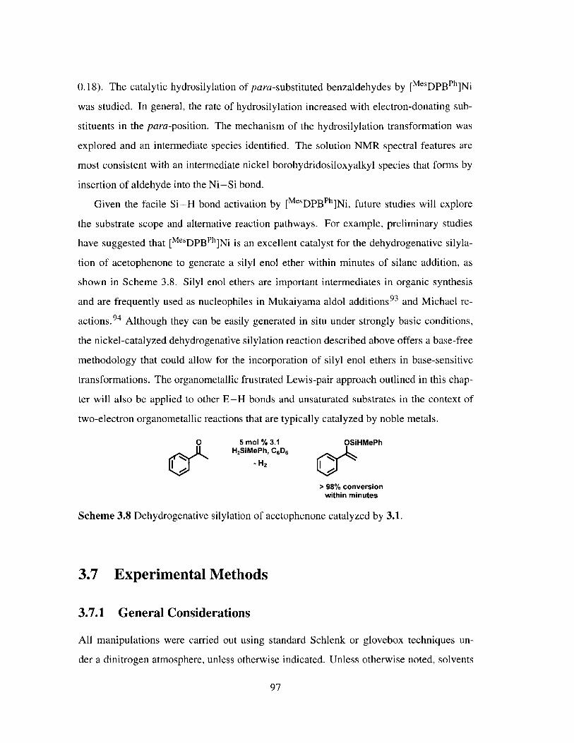
0.18). The catalytic hydrosilylation of para-substituted benzaldehydes by [MesDPBPh]Ni
was studied. In general, the rate of hydrosilylation increased with electron-donating sub-
stituents in the para-position. The mechanism of the hydrosilylation transformation was
explored and an intermediate species identified. The solution NMR spectral features are
most consistent with an intermediate nickel borohydridosiloxyalkyl species that forms by
insertion of aldehyde into the Ni-Si bond.
Given the facile Si-H bond activation by [MesDPBPh]Ni, future studies will explore
the substrate scope and alternative reaction pathways. For example, preliminary studies
have suggested that [MeDPBPh]Ni is an excellent catalyst for the dehydrogenative silyla-
tion of acetophenone to generate a silyl enol ether within minutes of silane addition, as
shown in Scheme 3.8. Silyl enol ethers are important intermediates in organic synthesis
and are frequently used as nucleophiles in Mukaiyama aldol additions 93 and Michael re-
actions. 94 Although they can be easily generated in situ under strongly basic conditions,
the nickel-catalyzed dehydrogenative silylation reaction described above offers a base-free
methodology that could allow for the incorporation of silyl enol ethers in base-sensitive
transformations. The organometallic frustrated Lewis-pair approach outlined in this chap-
ter will also be applied to other E-H bonds and unsaturated substrates in the context of
two-electron organometallic reactions that are typically catalyzed by noble metals.
0 5 mol % 3.1 OSiHMePh2SiMePh, C6 D6
-H2 0
> 98% conversionwithin minutes
Scheme 3.8 Dehydrogenative silylation of acetophenone catalyzed by 3.1.
3.7 Experimental Methods
3.7.1 General Considerations
All manipulations were carried out using standard Schlenk or glovebox techniques un-
der a dinitrogen atmosphere, unless otherwise indicated. Unless otherwise noted, solvents
97

were dried and deoxygenated by sparging with argon and passing through activated alu-
mina in a solvent purification system from SG Waters USA, LLC (Nashua, NH). Non-
halogenated solvents were tested with a standard purple solution of sodium benzophenone
ketyl in tetrahydrofuran in order to confirm effective oxygen and moisture removal. 3.139
and [a- 13C]-benzaldehyde 9 5 were prepared according to literature methods. D2 SiPh 2
was prepared via lithium aluminum deuteride (LAD) reduction of Cl2 SiPh2 in OEt2 . All
other reagents were purchased from commercial suppliers and used without further purifi-
cation. Elemental analyses were performed by Midwest Microlab, LLC (Indianapolis, IN)
and Robertson Microlit Laboratories, Inc (Ledgewood, NJ). Deuterated solvents were pur-
chased from Cambridge Isotope Laboratories, Inc., degassed, and dried over activated 3-A
molecular sieves prior to use.
3.7.2 Spectroscopic Measurements
Varian 300, 400 and 500 MHz spectrometers were used to record 'H, 13 C, 3 1p, 29 Si and
1 1B NMR spectra at room temperature, unless otherwise noted. 'H and 13C NMR chemical
shifts were referenced to the residual solvent peaks. 3 1P NMR chemical shifts were refer-
enced to external 85% phosphoric acid (3 = 0 ppm). 11B NMR chemical shifts were refer-
enced to external BF 3 -Et2 O (3 = 0 ppm). 2 9Si NMR chemical shifts were referenced to ex-
ternal tetramethylsilane. Infrared measurements were obtained in thin films using a Bruker
ALPHA FT-IR spectrometer equipped with a diamond ATR probe and OPUS/Mentor soft-
ware. GC-MS analyses were performed on an Agilent Technologies 6890N GC system
with an HP-5MS column.
3.7.3 Preparation of [MsDPBPh](H)NiSiH 2Ph (3.2)
To a solution of 3.1 (44.5 mg, 62.6 Mmol) in benzene (1 mL) was added neat H3 SiPh
(7.8 pL, 63.2 pmol). The solution was stirred 2 h at room temperature and pentane was
added to precipitate an orange powder. The slurry was stirred for another 30 min and the
solids collected. The solids were washed with pentane and dried in vacuo (36.6 mg, 71 %).
Crystals suitable for X-ray analysis were by slow evaporation of a OEt2 solution. 1H NMR
98

(400 MHz, C6D6 ) 3 7.63 (q, J = 5.8 Hz, 4H), 7.52 (d, J = 7.4 Hz, 2H), 7.33 - 7.22 (m, 6H),
7.14 - 7.07 (m, 4H), 7.06 - 6.82 (m, 17H), 6.43 (s, 2H), 4.30 (t, 3JHP = 9.2 Hz, 'JHSi =
138 Hz, 2H), 2.14 (s, 3H), 1.93 (s, 6H), -2.47 (s, 1H). 13C {H} NMR (101 MHz, C6D6 )
3 141.2, 136.5, 135.0, 133.8, 133.5, 130.6, 130.0, 129.8, 129.6, 128.9, 127.0, 126.3, 25.2,
20.6. 31p { 1H} NMR (162 MHz, C6D6 ) 3 41.1 (s). 29 Si{ 1H} NMR (79 MHz, C6D6) 3
- 17.0 (t, J = 38.7 Hz). 11B {'H} NMR (128 MHz, C6D6 ) 3 -2.2. IR (ATR, C6 6 film,
cm-1): 2060. Anal. Caled for C51H47BNiP2Si . OEt2 : C, 73.93; H, 6.43. Found: C, 74.05;
H, 6.13.
3.7.4 Preparation of [MesDPBPh](H)NiSiHPh 2 (3.3)
To a solution of 3.1 (59.4 mg, 83.5 pmol) in benzene (1 mL) was added neat H2 SiPh2
(16.4 gL, 88.1 pmol). The solution was stirred 2 h at room temperature and pentane was
added to precipitate a yellow powder. The slurry was stirred for another 30 min and the
solids collected. The solids were washed with pentane and dried in vacuo (56.8 mg, 76%).
Crystals suitable for X-ray analysis were by slow evaporation of a C6 H6 solution. 'H NMR
(400 MHz, toluene-d8) 3 7.69 (s, 4H), 7.43 (d, J = 7.5 Hz, 2H), 7.18 (s, 2H), 7.15 - 6.91
(m, 20H), 6.89 - 6.76 (m, 6H), 6.71 - 6.60 (m, 4H), 6.33 (s, 2H), 5.01 (t, 3 JHP = 14.7 Hz,
'JHSi = 88 Hz, 1H), 2.11 (s, 3H), 1.84 (s, 6H), -2.61 (s, 1H). 13C {'H} NMR (101 MHz,
C6D6 ) 3 141.2, 139.3, 137.1, 136.3, 135.6, 134.1, 133.8, 133.1, 130.5, 129.9, 129.8, 129.3,
128.9, 127.5, 127.4, 127.0, 126.3, 124.5, 25.4, 20.6. 31p 1H} NMR (162 MHz, C6D6) 3
40.9 (s). 29 Si{ 1H} NMR (79 MHz, C6D6) 3 3.1 (t, J = 37.9 Hz). 11B {1H} NMR (128
MHz, C6 D6 ) 3 -1.7. IR (ATR, C6 H6 film, cm- 1): 2058. Anal. Calcd for C57H51BNiP 2Si:
C, 76.45; H, 5.74. Found: C, 76.03; H, 5.99.
3.7.5 Preparation of [MesDPBPh](H)NiGeHPh 2 (3.4)
To a solution of 3.1 (44.3 mg, 62.3 pmol) in benzene (1 mL) was added neat H 2 GePh2
(11.8 ML, 63.5 pmol). The solution was stirred 12 h at room temperature, frozen and
lyophilized. Crystalline material was obtained by vapor diffusion of O(SiMe 3)2 into a
concentrated toluene solution. The solids were washed with O(SiMe3 )2 and dried in vacuo
99
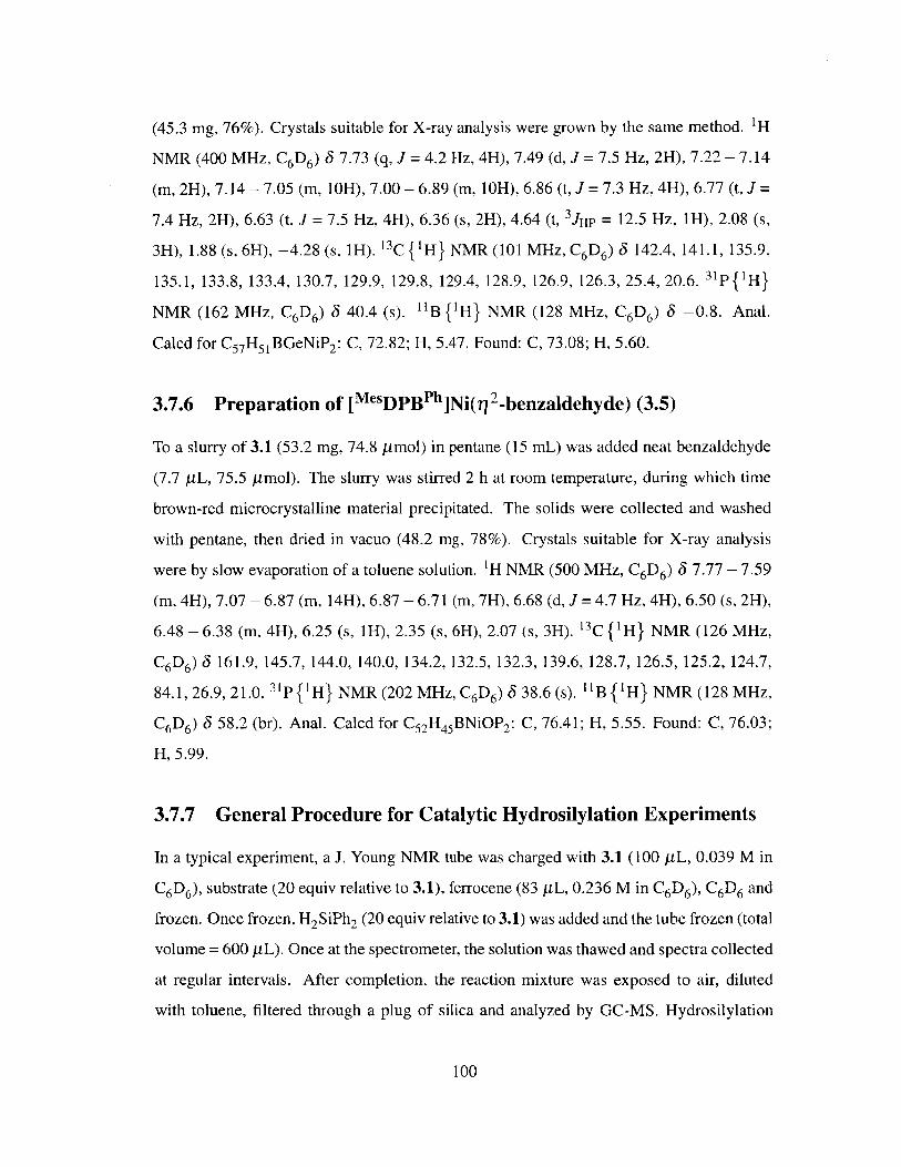
(45.3 mg, 76%). Crystals suitable for X-ray analysis were grown by the same method. 1H
NMR (400 MHz, C6D6) 3 7.73 (q, J = 4.2 Hz, 4H), 7.49 (d, J = 7.5 Hz, 2H), 7.22 - 7.14
(m, 2H), 7.14 - 7.05 (m, 10H), 7.00 - 6.89 (m, 10H), 6.86 (t, J = 7.3 Hz, 4H), 6.77 (t, J =
7.4 Hz, 2H), 6.63 (t, J = 7.5 Hz, 4H), 6.36 (s, 2H), 4.64 (t, 3jHP = 12.5 Hz, 1H), 2.08 (s,
3H), 1.88 (s, 6H), -4.28 (s, 1H). 13C {'H} NMR (101 MHz, C6D6) 3 142.4, 141.1, 135.9,
135.1, 133.8, 133.4, 130.7, 129.9, 129.8, 129.4, 128.9, 126.9, 126.3, 25.4, 20.6. 3 1P {'H}
NMR (162 MHz, C6D6) 3 40.4 (s). 11B {1H} NMR (128 MHz, C6D6) 3 -0.8. Anal.
Calcd for C57H51BGeNiP 2 : C, 72.82; H, 5.47. Found: C, 73.08; H, 5.60.
3.7.6 Preparation of [MesDPBPh]Ni(fl 2-benzaldehyde) (3.5)
To a slurry of 3.1 (53.2 mg, 74.8 pmol) in pentane (15 mL) was added neat benzaldehyde
(7.7 pL, 75.5 pmol). The slurry was stirred 2 h at room temperature, during which time
brown-red microcrystalline material precipitated. The solids were collected and washed
with pentane, then dried in vacuo (48.2 mg, 78%). Crystals suitable for X-ray analysis
were by slow evaporation of a toluene solution. 'H NMR (500 MHz, C6D 6 ) 3 7.77 - 7.59
(m, 4H), 7.07 - 6.87 (m, 14H), 6.87 - 6.71 (m, 7H), 6.68 (d, J = 4.7 Hz, 4H), 6.50 (s, 2H),
6.48 - 6.38 (m, 4H), 6.25 (s, 1H), 2.35 (s, 6H), 2.07 (s, 3H). 13C { 1H} NMR (126 MHz,
C6D6) 3 161.9, 145.7, 144.0, 140.0, 134.2, 132.5, 132.3, 139.6, 128.7, 126.5, 125.2, 124.7,
84.1, 26.9, 21.0. 31p {'H} NMR (202 MHz, C6D6) 3 38.6 (s). "B {'H} NMR (128 MHz,
C6D6) 3 58.2 (br). Anal. Calcd for C52H45BNiOP 2 : C, 76.41; H, 5.55. Found: C, 76.03;
H, 5.99.
3.7.7 General Procedure for Catalytic Hydrosilylation Experiments
In a typical experiment, a J. Young NMR tube was charged with 3.1 (100 PL, 0.039 M in
C6 D6 ), substrate (20 equiv relative to 3.1), ferrocene (83 jiL, 0.236 M in C6 D6 ), C6 D6 and
frozen. Once frozen, H2 SiPh2 (20 equiv relative to 3.1) was added and the tube frozen (total
volume = 600 pL). Once at the spectrometer, the solution was thawed and spectra collected
at regular intervals. After completion, the reaction mixture was exposed to air, diluted
with toluene, filtered through a plug of silica and analyzed by GC-MS. Hydrosilylation
100

products were identified using 1H NMR and GC-MS data in comparison to the literature
data.6 5 ,9 6,9 7 To aid characterization, (1-(4-trifluoromethylphenyl)methoxy)diphenylsilane
was converted to 4-(trifluoromethyl)phenyl methanol by treatment with 1 M HCl; the 1H
NMR and GC-MS data obtained agree with the literature data. 98
3.7.8 General Procedure for Stoichiometric Hydrosilylation Experi-
ments.
In a typical experiment, a J. Young NMR tube was charged with 3.1, [a- 13C]-benzaldehyde
(1 equiv relative to 3.1), toluene-d 8 (ca. 500 yL) and frozen. Once frozen, H2 SiPh2 (1 equiv
relative to 3.1) was added and the tube frozen. Once at the spectrometer, the solution was
thawed and pertinent spectra collected.
3.7.9 Mercury Tests for Homogeneity
Method 1: A solution of 3.1 (30 yL, 0.061 M, 5 mol %) in C 6 D6 was stirred with excess Hg
(0.0726 g, ca. 200 equiv per nickel atom) for 15 min. A solution of p-dimethylaminobenz-
aldehyde (0.0052 g, 34.8 ymol) and H2SiPh2 (6.5 yL, 35.0 ymol) in C6D6 was added
and the mixture stirred at 23 'C for 2 h. The solution was then filtered through Celite and
analyzed by 'H NMR spectroscopy. Complete hydrosilylation was observed.
Method 2: 3.1 (30 yuL, 0.061 M, 5 mol %) was added to a C6 D6 solution of p-dimethyl-
aminobenzaldehyde (0.0052 g, 34.8 imol) and H2SiPh 2 (6.5 yL, 35.0 ymol). The result-
ing solution was stirred for 5 min at 23 'C, then added to Hg (0.0465 g, ca. 125 equiv
per nickel atom) and stirred for 2 h at 23 'C. The mixture was filtered through Celite and
analyzed by 'H NMR spectroscopy. Complete hydrosilylation was observed.
3.7.10 Variable Temperature van't Hoff Study of the Equilibrium of
3.1 and 3.3
Ferrocene and 3.3 were dissolved in toluene-d 8 and transferred to a sealed J. Young NMR
tube. The tube was inserted into a temperature controlled NMR probe and 1H NMR spectra
101

were collected at 10 K intervals from 328 K to 368 K, allowing 20 min for equilibration at
each temperature. The concentrations of 3.1 and 3.3 were determined by integration of the
mesityl aryl C-H resonance for the respective complexes and H2 SiPh2 concentration was
assumed to be equal to the concentration of 3.1. The plot of ln(Kobs) as a function of T-1
was fit by a line and the enthalpy and entropy of the reaction were extracted from the slope
and intercept, respectively.
3.7.11 Variable Temperature van't Hoff Study of the Equilibrium of
3.1 and [MesDPBPh](D)Ni(SiDPh2)
Ferrocene, D2 SiPh 2 and 3.1 were dissolved in toluene-d8 and transferred to a sealed J.
Young NMR tube. The tube was inserted into a temperature controlled NMR probe and a
1H NMR spectra were collected at 10 K intervals from 298 K to 358 K, allowing 20 min for
equilibration at each temperature. The concentrations of 3.1 and [MesDPBPh](D)Ni(SiDPh 2 )
were determined by integration of the mesityl aryl C-H resonance for the respective com-
plexes and D2 SiPh 2 concentration was assumed to be equal to the concentration of 3.1.
3.7.12 2D 'H-1H EXSY study of the equilibrium of 3.1 and 3.3
2D 1 H- 1H EXSY spectra were collected using the samples prepared for the variable tem-
perature experiments outlined above. To determine the exchange rates of the equilibrium
between 3.1 and 3.3, two 2D EXSY experiments were acquired (mixing time, Tm = 0 ms
and 700 ms) at 10 K intervals from 328 K to 368 K, allowing 30 min for equilibration at
each temperature.
3.7.13 X-ray Crystallographic Details
Single crystals of 3.2 were obtained by slow evaporation of a OEt2 solution, crystals of
3.3 were grown by slow evaporation of a C6H 6 solution, crystals of 3.4 were obtained by
vapor diffusion of O(SiMe 3)2 into a concentrated toluene solution, crystals of 3.5 were
grown by slow evaporation of a toluene solution. Low-temperature single crystal X-ray
diffraction studies were carried out at the Beckman Institute Crystallography Facility on a
102
Bruker Kappa Apex II diffractometer with Mo Ka radiation (X =0.71073 A). Crystals were
coated with Paratone-N oil and mounted on glass fibers. Structures were solved by direct
or Patterson methods using SHELXS 9 9 and refined against F2 on all data by full-matrix
least squares with SHELXL-97 1 0 0 using established refinement techniques. '' All non-
hydrogen atoms were refined anisotropically. All hydrogen atoms (except the hydrogen
atoms bound to heteroatoms in 3.2, 3.3 and 3.4) were included into the model at geomet-
rically calculated positions and refined using a riding model. The isotropic displacement
parameters of all calculated hydrogen atoms were fixed to 1.2 times the U values of the
atoms they are linked to (1.5 times for methyl groups). Thermal ellipsoid diagrams were
created using Olex2.102 In the structure of 3.2, the OEt2 solvent molecule was disordered
over two sites. The structure of 3.5 contained one positionally disordered toluene solvent
molecule. The toluene molecule was refined anisotropically, however hydrogen atoms were
not added due to the complicated nature of the positional disorder. The crystallographic de-
tails for 3.2, 3.3, 3.4 and 3.5 are summarized in Tables 3.5 and 3.6.
103

3.2. OEt23.3 0.5 C6H6
Formula
Formula Weight
Temperature/K
Crystal syst.
Space group
Color
a/A
b/A
c/A
a/ 0
#/0y/0
V/3
p (calc.)/(gcm-)
z
No. refl.
No. unique refl.
Rint
RI (all data)a
wR2 (all data)b
R, [(I >2a)]
wR2 [(I >2c)]
GOF
C26.5OH26BO.5ONiO.5000.25psiO.50
428.25
100(2)
Triclinic
P!
Orange
11.6097(8)
13.0379(9)
17.3875(12)
68.361(4)
72.030(4)
64.875(4)
2178.5(3)
1.306
4
105776
13243
0.0472
0.0467
0.0904
0.0358
0.0831
1.036
C60H54BNiP 2Si
934.58
100(2)
Triclinic
P!
Yellow
12.1452(6)
20.3316(10)
21.4335(11)
69.986(3)
77.017(3)
82.180(3)
4835.7(4)
1.284
4
107064
19001
0.0675
0.0686
0.1192
0.0442
0.1068
1.021
104
Table 3.5 Crystallographic summary for 3.2,3.3 and 3.5. aR1 = EIlFo - Fe I/EIF I. bwR 2 =(E[w(Fo2 - F~)f/E[w(F 2 ) /2 cGOF = ( 0[w(F2 - F (n2)l/ 2 where n is thenumber of data and p is the number of parameters refined.
3.2 -OEt2 3.3 - 0.5 CAH

3.4 3.5 C7Formula
Formula Weight
Temperature/K
Crystal syst.
Space group
Color
a/A
b/A
c/A
a/ 0
P/0
y/0V/3
p (calc.)/(gcm-1)
zNo. refi.
No. unique refl.
Rint
RI (all data)a
wR 2 (all data)b
R1 [(I >2a)]
wR 2 [(I >2a)]
GOFc
C57 H 50 BGeNiP 2
939.02
100(2)
Triclinic
P!
Orange
9.626(2)
12.422(3)
20.146(4)
79.14(3)
77.22(3)
87.68(3)
2307.2(8)
1.352
2
89439
12960
0.0371
0.1092
0.1789
0.0845
0.1642
1.035
C 55 .5 0H 45 BNiOP 2
859.38
100(2)
Monoclinic
P21/n
Red
12.9166(8)
15.2418(9)
22.8933(15)
90
105.256(3)
90
4348.2(5)
1.313
4
250827
30670
0.0536
0.0710
0.1058
0.0385
0.0935
1.025
bwR2 =
n is the
105
Table 3.6 Crystallographic summary for 3.4 and 3.5. aR 1 I= EIFo - FeI/EIF0I1.(E[w(F2 - F) 2 /Ejw(F 2)2])1/ 2. cGOF = (E[w(F22 - F- p))1/ 2 wherenumber of data and p is the number of parameters refined.
3.4 3.5 ' C7

106

3.8 Bibliography
[1] Crabtree, R. H. The Organometallic Chemistry of the Transition Metals; John Wiley
& Sons: New York, 2001.
[2] Ball, Z. In Comprehensive Organometallic Chemistry III; Crabtree, R. H., Min-gos, D. M. P., Eds.; Elsevier: Oxford, UK, 2007; pp 789-813.
[3] Hayashi, T.; Yamasaki, K. In Comprehensive Organometallic Chemistry III; Crab-
tree, R. H., Mingos, D. M. P., Eds.; Elsevier: Oxford, UK, 2007; pp 815-838.
[4] Ojima, I. In The Chemistry of Organic Silicon Compounds; Patai, S., Rappoport, Z.,Eds.; John Wiley & Sons: Chichester, UK, 1989; pp 1479-1526.
[5] Marciniec, B. Silicon Chem. 2002, 1, 155-174.
[6] Magistrato, A.; Woo, T. K.; Togni, A.; Rothlisberger, U. Organometallics 2004, 23,3218-3227.
[7] Sakaki, S.; Mizoe, N.; Sugimoto, M. Organometallics 1998, 17, 2510-2523.
[8] Chalk, A. J.; Harrod, J. F. J. Am. Chem. Soc. 1965, 87, 16-21.
[9] Sakaki, S.; Sumimoto, M.; Fukuhara, M.; Sugimoto, M.; Fujimoto, H.; Matsuzaki, S.Organometallics 2002, 21, 3788-3802.
[10] Bergens, S. H.; Noheda, P.; Whelan, J.; Bosnich, B. J. Am. Chem. Soc. 1992, 114,2128-2135.
[11] Beddie, C.; Hall, M. B. J. Phys. Chem. A 2006, 110, 1416-1425.
[12] Beddie, C.; Hall, M. B. J. Am. Chem. Soc. 2004, 126, 13564-13565.
[13] Brunner, H. Angew. Chem. Int. Ed. 2004, 43, 2749-2750.
[14] Glaser, P. B.; Tilley, T. D. J. Am. Chem. Soc. 2003, 125, 13640-13641.
[15] Corey, J. Y. Chem. Rev. 2011, 111, 863-1071.
[16] Shimada, S.; Tanaka, M. Coord. Chem. Rev. 2006, 250, 991-1011.
[17] Corey, J. Y.; Braddock-Wilking, J. Chem. Rev. 1999, 99, 175-292.
[18] Nakata, N.; Fukazawa, S.; Kato, N.; Ishii, A. Organometallics 2011, 30, 4490-4493.
[19] Boyle, R. C.; Mague, J. T.; Fink, M. J. J. Am. Chem. Soc. 2003, 125, 3228-3229.
[20] Braddock-Wilking, J.; Zhang, Y; Corey, J. Y.; Rath, N. P. J. Organomet. Chem.2008, 693, 1233-1242.
107

[21] Arii, H.; Takahashi, M.; Noda, A.; Nanjo, M.; Mochida, K. Organometallics 2008,27, 1929-1935.
[22] Chan, D.; Duckett, S. B.; Heath, S. L.; Khazal, I. G.; Perutz, R. N.; Sabo-Etienne, S.;
Timmins, P. L. Organometallics 2004, 23, 5744-5756.
[23] Kim, Y.-J.; Choi, E.-H.; Lee, S. W. Organometallics 2003, 22, 3316-3319.
[24] Simons, R. S.; Sanow, L. M.; Galat, K. J.; Tessier, C. A.; Youngs, W. J.
Organometallics 2000, 19, 3994-3996.
[25] Ozawa, F.; Kamite, J. Organometallics 1998, 17, 5630-5639.
[26] Tsuji, Y.; Nishiyama, K.; Hori, S.-I.; Ebihara, M.; Kawamura, T. Organometallics
1998, 17, 507-512.
[27] Koizumi, T.-A.; Osakada, K.; Yamamoto, T. Organometallics 1997, 16, 6014-6016.
[28] Azizian, H.; Dixon, K. R.; Eaborn, C.; Pidcock, A.; Shuaib, N. M.; Vinaixa, J. I.Chem. Soc., Chem. Commun. 1982, 1020-1022.
[29] Eaborn, C.; Pidcock, A.; Ratcliff, B. J. Organomet. Chem. 1972, 43, C5-C6.
[30] Iluc, V. M.; Hillhouse, G. L. J. Am. Chem. Soc. 2010, 132, 11890-11892.
[31] Smith, E. E.; Du, G.; Fanwick, P. E.; Abu-Omar, M. M. Organometallics 2010, 29,6527-6533.
[32] Adhikari, D.; Pink, M.; Mindiola, D. J. Organometallics 2009, 28, 2072-2077.
[33] Kang, S. 0.; Lee, J.; Ko, J. Coord. Chem. Rev. 2002, 231, 47-65.
[34] Takaya, J.; Iwasawa, N. Dalton Trans. 2011, 40, 8814-8821.
[35] Iluc, V. M.; Hillhouse, G. L. Tetrahedron 2006, 62, 7577-7582.
[36] Chen, W.; Shimada, S.; Tanaka, M.; Kobayashi, Y.; Saigo, K. J. Am. Chem. Soc.2004, 126, 8072-8073.
[37] Zell, T.; Schaub, T.; Radacki, K.; Radius, U. Dalton Trans. 2011, 40, 1852-1854.
[38] Steinke, T.; Gemel, C.; Cokoja, M.; Winter, M.; Fischer, R. A. Angew. Chem. Int.
Ed. 2004, 43, 2299-2302.
[39] Harman, W. H.; Peters, J. C. J. Am. Chem. Soc. 2012, 134, 5080-5082.
[40] MacMillan, S. N.; Harman, W. H.; Peters, J. C. Manuscript in Preparation.
[41] Liu, S.; Liu, F.-C.; Renkes, G.; Shore, S. G. Organometallics 2001, 20, 5717-5723.
[42] Arndt, P.; Baumann, W.; Spannenberg, A.; Rosenthal, U.; Burlakov, V. V.;
Shur, V. B. Angew. Chem. Int. Ed. 2003, 42, 1414-1418.
108

[43] Al-Humydi, A.; Garrison, J. C.; Mohammed, M.; Youngs, W. J.; Collins, S. Polyhe-dron 2005, 24, 1234-1249.
[44] Choukroun, R.; Lorber, C.; Vendier, L.; Lepetit, C. Organometallics 2006, 25, 1551-1553.
[45] Arndt, P.; Jager-Fiedler, U.; Klahn, M.; Baumann, W.; Spannenberg, A.;Burlakov, V. V.; Rosenthal, U. Angew. Chem. Int. Ed. 2006, 45, 4195-4198.
[46] Lansing, R. B., Jr.; Goldberg, K. I.; Kemp, R. A. Dalton Trans. 2011, 40, 8950-8958.
[47] Lin, S.; Day, M. W.; Agapie, T. J. Am. Chem. Soc. 2011, 133, 3828-3831.
[48] Hatnean, J. A.; Beck, R.; Borrelli, J. D.; Johnson, S. A. Organometallics 2010, 29,6077-6091.
[49] Boro, B. J.; Duesler, E. N.; Goldberg, K. I.; Kemp, R. A. Inorg. Chem. 2009, 48,5081-5087.
[50] Steinke, T.; Shaw, B. K.; Jong, H.; Patrick, B. 0.; Fryzuk, M. D. Organometallics
2009, 28, 2830-2836.
[51] Laird, M. F.; Pink, M.; Tsvetkov, N. P.; Fan, H.; Caulton, K. G. Dalton Trans. 2009,1283-1285.
[52] Chakraborty, S.; Krause, J. A.; Guan, H. Organometallics 2009, 28, 582-586.
[53] Liang, L.-C.; Chien, P.-S.; Lee, P.-Y. Organometallics 2008, 27, 3082-3093.
[54] Aresta, M.; Quaranta, E.; Dibenedetto, A.; Giannoccaro, P.; Tommasi, I.; Lan-
franchi, M.; Tiripicchio, A. Organometallics 1997, 16, 834-84 1.
[55] Muller, U.; Keim, W.; KrUger, C.; Betz, P. Angew. Chem. Int. Ed. Engl. 1989, 28,1011-1013.
[56] Stoelzel, M.; Prisang, C.; Inoue, S.; Enthaler, S.; Driess, M. Angew. Chem. Int. Ed.2012, 51, 399-403.
[57] Tavear, G.; Sen, S. S.; Azhakar, R.; Thorn, A.; Roesky, H. W. Inorg. Chem. 2010,49, 10199-10202.
[58] Meltzer, A.; Inoue, S.; Prasang, C.; Driess, M. J. Am. Chem. Soc. 2010, 132, 3038-3046.
[59] Meltzer, A.; Prasang, C.; Driess, M. J. Am. Chem. Soc. 2009, 131, 7232-7233.
[60] Schaub, T.; D6ring, C.; Radius, U. Dalton Trans. 2007, 1993-2002.
[61] Churchill, D. G.; Janak, K. E.; Wittenberg, J. S.; Parkin, G. J. Am. Chem. Soc. 2003,125, 1403-1420.
109

[62] Pastor, A.; Martifnez-Viviente, E. Coord. Chem. Rev. 2008, 252, 2314-2345.
[63] Pons, M.; Millet, 0. Prog. Nucl. Magn. Reson. Spectrosc. 2001, 38, 267-324.
[64] EXSYCalc. http: //www.mestrec.com/.
[65] Tondreau, A. M.; Lobkovsky, E.; Chirik, P. J. Org. Lett. 2008, 10, 2789-2792.
[66] Ram6n, D. J.; Yus, M. Chem. Rev. 2006, 106, 2126-2208.
[67] Bandini, M.; Bernardi, F.; Bottoni, A.; Cozzi, P. G.; Miscione, G. P.; Umani-
Ronchi, A. Eur. J. Org. Chem. 2003, 2972-2984.
[68] Beagley, P.; Davies, P. J.; Blacker, A. J.; White, C. Organometallics 2002, 21, 5852-5858.
[69] Yun, J.; Buchwald, S. L. J Am. Chem. Soc. 1999, 121, 5640-5644.
[70] Darwish, M.; Wills, M. Catal. Sci. Technol. 2012, 2, 243-255.
[71] Junge, K.; Schr6der, K.; Beller, M. Chem. Commun. 2011, 47, 4849-4859.
[72] Chirik, P. J. Catal. Precious Met. 2010, 83-110.
[73] Zhang, M.; Zhang, A. Appl. Organomet. Chem. 2010, 24, 751-757.
[74] Morris, R. H. Chem. Soc. Rev. 2009, 38, 2282-2291.
[75] Kundu, S.; Brennessel, W. W.; Jones, W. D. Inorg. Chem. 2011, 50, 9443-9453.
[76] Tran, B. L.; Pink, M.; Mindiola, D. J. Organometallics 2009, 28, 2234-2243.
[77] Fontaine, F.-G.; Zargarian, D. Organometallics 2002, 21, 401-408.
[78] Lipshutz, B. H. Synlett 2009, 4, 509-524.
[79] Diez-Gonzailez, S.; Nolan, S. P. Acc. Chem. Res. 2008, 41, 349-358.
[80] Rendler, S.; Oestreich, M. Angew. Chem. Int. Ed. 2007, 46, 498-504.
[81] Ojima, I.; Kogure, T.; Kumagai, M.; Horiuchi, S.; Sato, T. J. Organomet. Chem.
1976, 122, 83-97.
[82] Zheng, G. Z.; Chan, T. H. Organometallics 1995, 14, 70-79.
[83] Tolman, C. A.; English, A. D.; Manzer, L. E. Inorg. Chem. 1975, 14, 2353-2356.
[84] Matas, I.; Campora, J.; Palma, P.; Alvarez, E. Organometallics 2009, 28, 6515-6523.
[85] Ogoshi, S.; Ueta, M.; Arai, T.; Kurosawa, H. J. Am. Chem. Soc. 2005, 127, 128 10-12811.
[86] Walther, D. J. Organomet. Chem. 1980, 190, 393-401.
110

[87] Akita, M.; Mitani, 0.; Sayama, M.; Moro-oka, Y. Organometallics 1991, 10, 1394-1399.
[88] Gregg, B. T.; Hanna, P. K.; Crawford, E. J.; Cutler, A. R. J. Am. Chem. Soc. 1991,113, 384-385.
[89] Hanna, P. K.; Gregg, B. T.; Cutler, A. R. Organometallics 1991, 10, 31-33.
[90] Akita, M.; Mitani, 0.; Moro-oka, Y. J. Chem. Soc., Chem. Commun. 1989, 527-529.
[91] Selover, J. C.; Vaughn, G. D.; Strouse, C. E.; Gladysz, J. A. J. Am. Chem. Soc. 1986,108, 1455-1462.
[92] Gladysz, J. A. Acc. Chem. Res. 1984, 17, 326-332.
[93] Mukaiyama, T.; Narasaka, K.; Banno, K. Chem. Lett. 1973, 1011-1014.
[94] Miyashita, M.; Yanami, T.; Kumazawa, T.; Yoshikoshi, A. J. Am. Chem. Soc. 1984,106, 2149-2156.
[95] Blake, M. E.; Bartlett, K. L.; Jones, M., Jr. J. Am. Chem. Soc. 2003, 125, 6485-6490.
[96] Wei, Y.; Han, S.; Kim, J.; Soh, S.; Grzybowski, B. A. J. Am. Chem. Soc. 2010, 132,11018-11020.
[97] Yang, J.; Tilley, T. D. Angew. Chem. Int. Ed. 2010, 49, 10186-10188.
[98] Nagendra, G.; Madhu, C.; Vishwanatha, T. M.; Sureshbabu, V. V. Tetrahedron Lett.2012,53,5059-5063.
[99] Sheldrick, G. M. Acta Cryst. 1990, A46, 467-473.
[100] Sheldrick, G. M. SHELXL-97: Program for Crystal Structure Refinement. Univer-sity of Gottingen, G6ttingen, Germany, 1997.
[101] MUller, P. Crystallogr. Rev. 2009, 15, 57-83.
[102] Dolomanov, 0. V.; Bourhis, L. J.; Gildea, R. J.; Howard, J. A. K.; Puschmann, H. J.Appl. Cryst. 2009, 42, 339-341.
111

112

Isolation of an Unusual Nickel(I)
Borohydridothiolate Complex
Introduction . . . . . . . . . . . . . . . . . . . . . . . . . . . . . . . 114
Isolation of a Nickel(II) Borohydridothiolate Complex . . . . . . . . 116
Substituent Effects on S-H Bond Activation . . . . . . . . . . . . . 118
Isolation of a Nickel(I) Borohydridothiolate Complex . . . . . . . . 121
Ni K-Edge XAS Studies . . . . . . . . . . . . . . . . . . . . . . . . . 125
Conclusions and Future Work . . . . . . . . . . . . . . . . . . . . . 126
Experimental Methods . . . . . . . . . . . . . . . . . . . . . . . . . 127
4.7.1 General Considerations . . . . . . . . . . . . . . . . . . . . . . 127
4.7.2 Spectroscopic Measurements . . . . . . . . . . . . . . . . . . . 128
4.7.3 Electrochemistry . . . . . . . . . . . . . . . . . . . . . . . . . 128
4.7.4 X-ray Spectroscopy . . . . . . . . . . . . . . . . . . . . . . . . 129
4.7.5 DFT Calculations . . . . . . . . . . . . . . . . . . . . . . . . . 129
4.7.6 Preparation of [MesDPBPh](H)Ni(SPh) (4.1) . . . . . . . . . . . 129
4.7.7 In situ Preparation of a Series of Borohydridothiolate Complexes
(4.2 - 4.6) . . . . . . . . . . . . . . . . . . . . . . . . . . . . .
4.7.8 Preparation of [[MesDPBPh](H)Ni(SPh)][CoCpg] (4.7) . . . . .
4.7.9 X-ray Crystallographic Details . . . . . . . . . . . . . . . . . .
113
4
Contents
4.1
4.2
4.3
4.4
4.5
4.6
4.7
130
132
132

4.8 Bibliography ..................................... 135
4.1 Introduction
Hydrothiolation, much like the hydrosilylation processes discussed in Chapter 3, is a well-
recognized synthetic method for the functionalization of unsaturated substrates with 100%
atom efficiency. 1 The addition of S-H bonds to alkynes offers a stunning array of mech-
anistic pathways, including radical, 2 - nucleophilic 7'8 and metal-mediated processes. 9-12
In general, however, these reactions can be grouped into two classes: those that activate
the alkyne substrate and those that activate the thiol. For non-metal-mediated catalysis,
the products of hydrothiolation are the anti-Markovnikov species shown in Scheme 4.1
(left). The ratio of the cis and trans olefins is dependent on the substituents (R, Ar) and
the reaction conditions. 13 Interestingly, for metal-mediated transformations a change in the
regioselectivity of the thiol addition can occur and a-vinyl sulfides can be obtained with
varying degrees of selectivity (Scheme 4.1, right). In the presence of some transition-metal
catalysts, the desired a-vinyl sulfide isomerizes to a mixture of cis and trans olefins. 14 '15
H R
ArS Free radical or Metal-mediatednucleophilic addition addition H R
+ H -"R +ArSH VH H H SAr
ArS R
Scheme 4.1 Hydrothiolation pathways for (left) radical or nucleophilic addition and (right)metal-mediated addition of thiols to alkynes.
Thiol S-H bonds can be activated by transition metals either through an acid/base reac-
tion to generate a metal thiolate complex or by oxidative addition of the S-H bond to yield
a metal hydride thiolate species. 13 The acid/base activation pathway is typically observed
for transition-metal catalysts containing palladium and nickel, 15-18 while the oxidative ad-
dition route is usually observed for rhodium-based catalysts. 14,19-21 The oxidative addition
pathway is particularly intriguing, as the formation of a metal hydride thiolate complex
may allow for ligand-based control of the alkyne insertion into either the M-S or M-H
114

bonds, thereby determining the regioselectivity of the reaction. 13 This principle is illus-
trated in Scheme 4.2. The electronically and sterically preferred 1,2-insertion (rather than
2,1 -insertion) of an alkyne into the M-H bond gives rise to linear thioether products, while
insertion into the M-S bond yields the Markovnikov vinyl sulfide. A non-precious-metal
catalyst that could selectively direct alkyne insertion into the M-S bond rather than the
M-H bond would therefore be an important advance in the preparation of branched vinyl
sulfides.
R" H HR' H HI " - IM-S
SR[M].SR RS H S
Scheme 4.2 (left) Alkyne insertion into the M-H bond results in the formation of linearthioether products. (right) Insertion into the M-S bond forms branched Markovnikov vinylsulfide compounds.
Nickel-based catalysts have recently emerged as more economic alternatives to tra-
ditional palladium hydrothiolation catalysts. For example, NiCl2 catalyzes the addition
of thiophenol to 1-heptyne; the addition of NEt3 dramatically increased the yield of the
Markovnikov addition product (15% vs 84%).18 During hydrothiolation with a number
of nickel-based catalysts, there is evidence for the formation of polymeric (and poten-
tially insoluble) nickel thiolate species (e.g., [Ni(SPh) 2]).13 In response to this concern,
Nolan introduced the use of a series of complexes of the form [CpNi(NHC)Cl] (NHC =
N-heterocyclic carbene) as strictly homogeneous catalysts and mechanistic studies have
invoked the formation of a monothiolate organonickel species as an intermediate along
the catalytic pathway.' From these examples, it is clear that while significant advances in
nickel-catalyzed hydrothiolation are being made, this chemistry is dominated by acid/base
chemistry (i.e., necessity of NEt3, formation of thiolate complexes) and so the preparation
of isolable nickel hydride thiolate complexes derived directly from S-H oxidative addition
is a worthwhile pursuit of fundamental interest.
Nickel thiolate complexes are also important in biological catalysis. Eight nickel-
containing enzymes have been identified that perform a variety of important transforma-
tion;22,23 four of these eight enzymes contain nickel thiolate bonds in their active sites.
Nickel superoxide dismustate (Ni-SOD) catalyzes the disproportionation of superoxide into
115

02 and hydrogen peroxide. 24 NiFe hydrogenase reversibly reduces protons to H2-25 CO
dehydrogenase (CODH) reversibly interconverts CO and C02.26,27 Acetyl-CoA synthetase
produces acetyl-coenzyme A (acetyl-CoA) from CO, CoA and a methyl group. 28,29 For
each of these systems, the nickel sites are flexible in both their coordination number and
redox chemistry, with the nickel(I), nickel(II) and nickel(III) oxidation states implicated in
several catalytically relevant species. 30-32
As described in Chapter 3, the bis(phosphine)borane nickel complex [MesDPBPh]Ni
(3.1) activates Si-H bonds under ambient conditions to generate isolable nickel borohy-
dridosilyl species. Having demonstrated facile E-H bond activation, we sought to broaden
the scope of these reactions to include other substrates, such as N-H, O-H and S-H
bonds. While we were unable to effect either N-H or O-H bond activation, the S-H
bonds of arylthiols were easily activated. Described in this chapter are the preparation of
a series of well-defined nickel borohydridothiolate complexes and the isolation of a rare
nickel(I) borohydridothiolate species. Catalytic functionalization reactions incorporating
S-H bond activation by [MesDPBPh]Ni have yet to be realized, however the chemistry
describe herein provides a starting point for their development.
4.2 Isolation of a Nickel(II) Borohydridothiolate Complex
Treatment of a C6H6 solution of 3.1 with 1 equiv HSPh resulted in an immediate color
change from dark brown to emerald green. Analysis of the crude reaction mixture after 2
hr by 'H and 31p {1H} NMR spectroscopy indicated the quantitative consumption of 3.1
and the formation of a new diamagnetic product, [MesDPBPh](H)Ni(SPh) (4.1, Scheme 4.3).
After workup, 4.1 was obtained as a dark green powder in ca. 85% yield. The 'H NMR
spectrum of 4.1 features resonances from 8 to -13 ppm; a broad triplet centered at -12.23
ppm integrates to one proton and is attributed to the bridging borohydride ligand. The
triplet pattern arises from the coupling of the proton to two equivalent phosphorus nuclei
( 2jHP = 26.1 Hz). Interesting to note is that for the related nickel borohydridosilyl and
borohydridogermyl complexes discussed in Chapter 3 and the borohydridohydride species
previously reported,33 no coupling of the bridging borohydride resonance to phosphorus
116

could be resolved in the 'H NMR spectrum, even upon cooling to -60 0C. The 31P {1 H}
NMR spectrum of 4.1 features a singlet at 37.9 ppm. At -80 'C, the phosphorus nuclei are
inequivalent and split into two doublets centered at 50.7 ppm (1 Jpp = 280.4 Hz) and 39.4
ppm (1 Jpp = 280.7 Hz).
P HC HPh Green powdr
P
Ph 2(4.1)
Scheme 4.3 Treatment of 3.1 with 1 equiv HSPh yields the green borohydridothiolate com-plex 4.1.
Complex 4.1 is soluble in THF, OEt2, C6H6 and pentane. Single crystals were obtained
by vapor diffusion of O(SiMe 3)2 into a concentrated toluene solution of 4.1. Complex 4.1
crystallizes in the monoclinic space group P21 with one molecule per asymmetric unit. The
geometry at nickel is distorted square planar with two trans-disposed phosphine donors, a
terminal thiolate group and a hydride bridging the nickel and boron centers (Figure 4.1).
Consistent with a distorted square planar geometry is the observation that the P1 -Ni-P2
and S-Ni-HOO angles are non-linear (160.16(1)0 and 165.1(6)0, respectively) and that
the nickel center lies slightly outside the P1 -S-P2 plane (0.308 A). The average Ni-P
bond length of 2.1804(3) A falls within the range (2.10 - 2.27 A) for other structurally
characterized, four-coordinate nickel bis(phosphine) complexes. This Ni-S distance of
2.1782(3) A is also typical of other four-coordinate mononuclear nickel complexes con-
taining monodentate thiolate ligands (2.12 - 2.34 A).
While the formation of hydride thiolate complexes via oxidative addition of an S-H
bond of H2S is well-documented, the analogous reaction with thiols is rare. To our knowl-
edge, 4.1 is the second structurally characterized nickel hydride thiolate complex, the
first being the N-heterocyclic carbene (NHC) supported complex, Ni(iPr2Im)2(H)(S t Bu)
(iPr2Im = 1,3-diisopropyl-imidazol-2-ylidene), reported by Radius.34 The solid-state struc-
ture of this species is similar to 4.1 and features a nickel center with two trans-disposed
NHC ligands, an alkylthiolate moiety and a terminal hydride. The bond angles around
nickel are distorted from ideal square planar geometry due to the steric interaction of
117

Selected Bond Lenaths (A) and Anales (0)NI-P1 = 2.1585(3)NI-P2 = 2.2023(3)NI-S = 2.1782(3)NI-H100 = 1.50(1)NI-B = 2.511(1)
B-HIOO = 1.35(2)PI-NI-P2 = 160.16(6)S-NI-HIOO = 165.1(6)
Figure 4.1 Solid-state structure of 4.1. Thermal ellipsoids are drawn at 40% probability.Hydrogen atoms except for the bridging borohydride (H100) are omitted for clarity.
the NHC ligands and the alkylthiolate ligand (C19-Ni-H = 86.57(2)0, Cl-Ni-H =
75.82(2)0, C19-Ni-S = 89.7(1) and Cl-Ni-S = 107.8(l)'). Complex 4.1 is not as dis-
torted (P1 -Ni-H = 89.0(6)0, P2-Ni-H = 86.8(6)0, P1-Ni-S = 91.32(1)0 and P2-Ni-S
= 97.55(1 )). In this case, the phenyl group of the thiolate rotates such that it is perpen-
dicular to the P1-S-P2 plane (88.320), thereby alleviating the need for a more distorted
geometry. The structural parameters of these two species are compared in Figure 4.2.
Cl-Ni-H = 75.82(2)0C19-NI-H = 86.57(2)0Cl-NI-S = 107.8(1)*C19-NI-S = 89.7(1)*
Pr HPr
N I
I NPr! iBuS IO~r O~r
- h2
I WB-H7-ISPhPPh22
Figure 4.2 Comparison of an NHC-supported nickel hydride thiolatethe bis(phosphine)borane complex 4.1 (right).
P1-NI-H = 89.0(6)*P2-NI-H = 86.8(6)0P1-NI-S = 91.32(1)*P2-NI-S = 97.55(1)0
complex (left) and
4.3 Substituent Effects on S-H Bond Activation
Having established facile S-H bond activation of HSPh with 3.1, the activation of para-
substituted thiophenols was investigated. Treatment of a C6H6 solution 3.1 with 1 equiv of
p-X-thiophenol (X = NH2, (4.2); Cl, (4.3); F, (4.4); CF 3, (4.5); OMe, (4.6)) yielded the cor-
responding nickel borohydridothiolate complex (Scheme 4.4). The 31p f IH} NMR spectra
of all the borohydridothiolate complexes feature a singlet between 37 and 42 ppm. The 1H
118
P 1
HMOO Ni i
P2

NMR spectra are also very similar; each spectrum contains a broad triplet centered between
-12 and -13 ppm that corresponds to the bridging borohydride ligand. The 2 JHP coupling
could not be resolved for 4.2 and a broad singlet rather than a triplet was observed. The
11 B{ 1H} NMR spectra each display a singlet centered at ca. 5 ppm. The lack of change
between the various NMR spectra for 4.2 - 4.6 suggests that their ground state solution
structures are similar. The NMR spectroscopic features of the nickel borohydridothiolate
complexes are summarized in Table 4.1.
PPh 2
HSCHX
CSHC,
x
-. PPh 2 l
X = NH 2 (4.2)CI (4.3)F (4.4)
CF3 (4.5)OMe (4.6)
Scheme 4.4 Preparation of para-substituted thiolate complexes 4.2 - 4.6.
X H ppm (m) 3 1P{ 1H} ppm (m) 11B {H} ppm (m)
4.1 H -12.23 (t, 2 jHP = 26.1 Hz) 37.9 4.8
4.2 NH2 -12.31 (s) 37.7 3.4
4.3 C1 -12.34 (t, 2jHP = 26.4 Hz) 38.4 5.1
4.4 F -12.36 (t, 2 JHP = 26.2 Hz) 39.3 4.8
4.5 CF3 -12.23 (t, 2 jHP = 26.3 Hz) 40.8 5.8
4.6 OMe -12.29 (t, 2 jHP = 26.2 Hz) 37.9 4.9
Table 4.1 Comparison of the signature NMR resonances of borohydridothiolate complexes.
Single crystals of 4.4 and 4.6 were obtained and their solid-state structures determined
by X-ray crystallographic analysis. Complex 4.4 crystallizes in the monoclinic space group
C2/c with one molecule in the asymmetric unit; complex 4.6 crystallizes in the triclinic
space group PI with one molecule in the asymmetric unit (Figure 4.3). Each complex fea-
tures a nickel center in a distorted square planar geometry, with two trans-phosphines, a
terminal thiolate ligand and a hydride bridging the nickel and boron centers. Overall, the
structural parameters of 4.4 and 4.6 are very similar to those of 4.1 and are summarized in
119
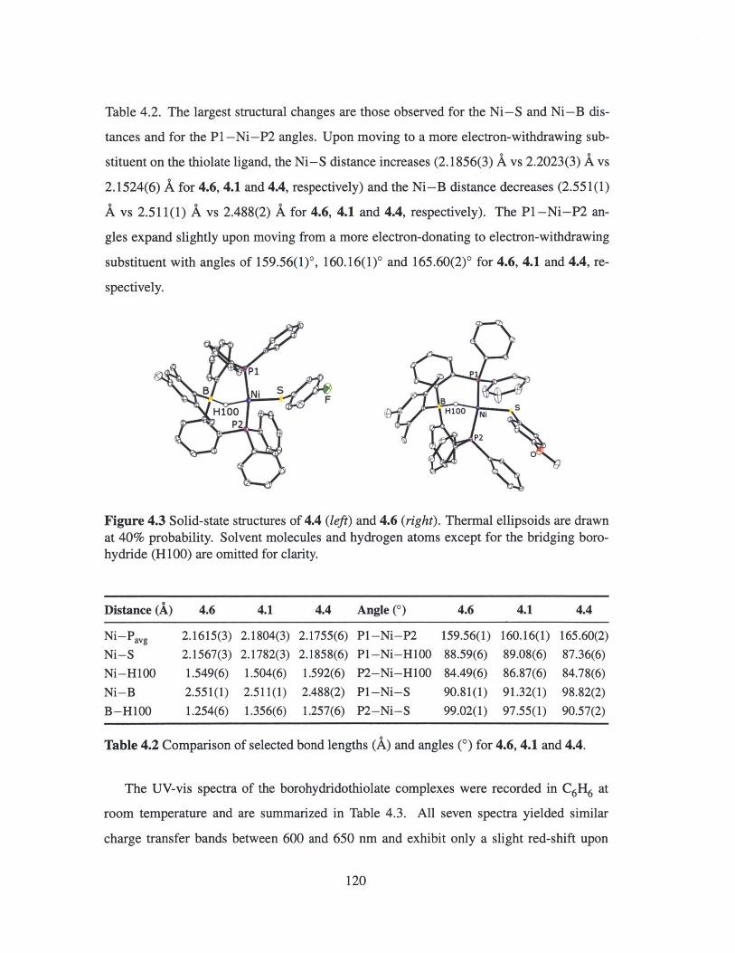
Table 4.2. The largest structural changes are those observed for the Ni-S and Ni-B dis-
tances and for the P1 -Ni-P2 angles. Upon moving to a more electron-withdrawing sub-
stituent on the thiolate ligand, the Ni-S distance increases (2.1856(3) A vs 2.2023(3) A vs
2.1524(6) A for 4.6, 4.1 and 4.4, respectively) and the Ni-B distance decreases (2.55 1(1)
A vs 2.511(1) A vs 2.488(2) A for 4.6, 4.1 and 4.4, respectively). The Pl-Ni-P2 an-
gles expand slightly upon moving from a more electron-donating to electron-withdrawing
substituent with angles of 159.56(1)0, 160.16(1)' and 165.60(2)0 for 4.6, 4.1 and 4.4, re-
spectively.
H100 Ni
P2
Figure 4.3 Solid-state structures of 4.4 (left) and 4.6 (right). Thermal ellipsoids are drawnat 40% probability. Solvent molecules and hydrogen atoms except for the bridging boro-hydride (H100) are omitted for clarity.
Distance (A)
Ni-Pavg
Ni-S
Ni-HOO
Ni-B
B-H100
4.6
2.1615(3)2.1567(3)1.549(6)
2.551(1)
1.254(6)
4.1
2.1804(3)
2.1782(3)1.504(6)
2.511(1)
1.356(6)
4.4
2.1755(6)
2.1858(6)
1.592(6)
2.488(2)1.257(6)
Angle (0)
P1 -Ni-P2
P1-Ni-HOO
P2-Ni-H1OO
P1-Ni-S
P2-Ni-S
Table 4.2 Comparison of selected bond lengths (A) and angles (0) for 4.6, 4.1 and 4.4.
The UV-vis spectra of the borohydridothiolate complexes were recorded in C6H6 at
room temperature and are summarized in Table 4.3. All seven spectra yielded similar
charge transfer bands between 600 and 650 nm and exhibit only a slight red-shift upon
120
4.6
159.56(1)
88.59(6)84.49(6)
90.81(1)99.02(1)
4.1
160.16(1)
89.08(6)86.87(6)91.32(1)
97.55(1)
4.4
165.60(2)87.36(6)84.78(6)98.82(2)90.57(2)
Pi
B Ni
H100 pP

moving to more electron-withdrawing substituents in the para position of the thiolate. The
order parallels the relative electron-rich character of the aryl 7r system, consistent with
S-Ni (p)n7-(d)7r* LMCT character. The small red-shift in the charge transfer band suggests,
as did the similar NMR spectroscopic features, that the borohydridothiolate complexes
share a common ground state structure.
R ALmax (nm)
4.1 H 630
4.2 NH2 659
4.3 Cl 610
4.4 F 615
4.5 CF3 600
4.6 OMe 635
Table 4.3 Maximum absorption wavelengths in the UV-vis spectra of the nickel boro-
hydrido-thiolate complexes in C6 H6 4.1 - 4.6.
The distinct LMCT band for each complex offers a spectroscopic handle and the oppor-
tunity to monitor the kinetics of S-H bond activation by UV-vis spectroscopy. However,
cleavage of the S-H bond to yield the borohydridothiolate complex is extremely rapid,
even at -80 'C, precluding a kinetics analysis.
4.4 Isolation of a Nickel(I) Borohydridothiolate Complex
A large number of square planar nickel(II) dithiolate/thioether compounds with S, (N,S),
(P,S) and (0, S) donor ligands have been described and their structural, electronic and
redox properties studied in depth (Figure 4.4).30 Such complexes generally have rich elec-
trochemistry, and both nickel(I) and nickel(III) species have been prepared in situ and stud-
ied by EPR spectroscopy.3 3 2 ,35 The cyclic voltammograms of the complexes shown in
Figure 4.4 each feature reversible or quasi-reversible reduction features assigned as a re-
duction from nickel(II) to nickel(I) (A: -1.50 V; B: -1.59 V; C: -1.56 V; D: ca. -1.60
V; vs Fc/Fc'). 36- 39 EPR spectroscopic analysis confirms the assignment of the metal-based
reduction, as the spectra each exhibit feature anisotropic g-values and gis, values greater
121

than 2. In addition, g1l > g_, similar to most other S = 1/2 nickel(I) complexes. None of
these species have been structurally characterized, as synthetic nickel(I) thiolate complexes
tend to be unstable with respect to disproportionation to nickel(II) and nickel(0) species. 4 0
/ Me Me O
B Ni B Ni Ni/o _10 \_ \
Me Me
A B
N Sp2 + r \ R 2Ph2 AN
Ph 2 SR2
C D
Figure 4.4 Examples of square-planar nickel(II) dithiolate/thioether complexes with vari-
ous donors in the coordination sphere: S4 (A); 3 6 NS 3 (B); 37 P2 S 2 (C);3 8 ON 2 S (D). 3 9
The cyclic voltammogram of 4.1 in THF exhibits two redox features: a quasi-reversible
event centered at -1.61 V vs Fc/Fc' and a second, irreversible event centered at ca. -2.60
V vs Fc/Fc'. The quasi-reversible feature, assigned as the reduction of 4.1 from Ni(II) to
Ni(I), is shown in Figure 4.5. At 100 mV/s, AEp ~ 200 mV and increases with decreasing
scan rate. Even though a plot of ip vs v1/ 2 is linear, ipc/ipa is not equal to 1, further illustrat-
ing that this redox event is not a reversible feature. The Ni(II)/Ni(I) reduction potential ob-
served here is similar to other square planar nickel complexes ligated by sulfur-containing
ligands. 35 For example, the dinuclear (pyridine-2,6-dimethanethiolato)nickel(II) complex
[Ni(pmt)] 2 reported by Holm is reduced at -1.21 V vs SCE in DMF (-1.59 V vs Fc/Fc*). 37
In contrast, the Ni(II)/Ni(I) couple of the related pseudotetrahedral tris(phosphine)borate
complex [PhBP h]Ni(S-p-'BuPh) reported by Peters is shifted ca. 500 mV anodically,
at -1.12 V vs Fc/Fc'. 4 1 The irreversible Ni(II)/Ni(I) couple of [NiL] (L2 - = 2,2'-(2,2'-
bipyridine-6,6'-diyl)bis(1,1-diphenylethanethiolate)) reported by Collomb is shifted 300
mV cathodically, at -1.91 V vs Fc/Fc'. 4 2
The reduced complex, [[MesDPBPh](H)Ni(SPh)][CoCp*] (4.7), was accessed by reduc-
tion of a toluene solution of 4.1 with 1.1 equiv CoCp*, as shown in Figure 4.5. This brown,
122
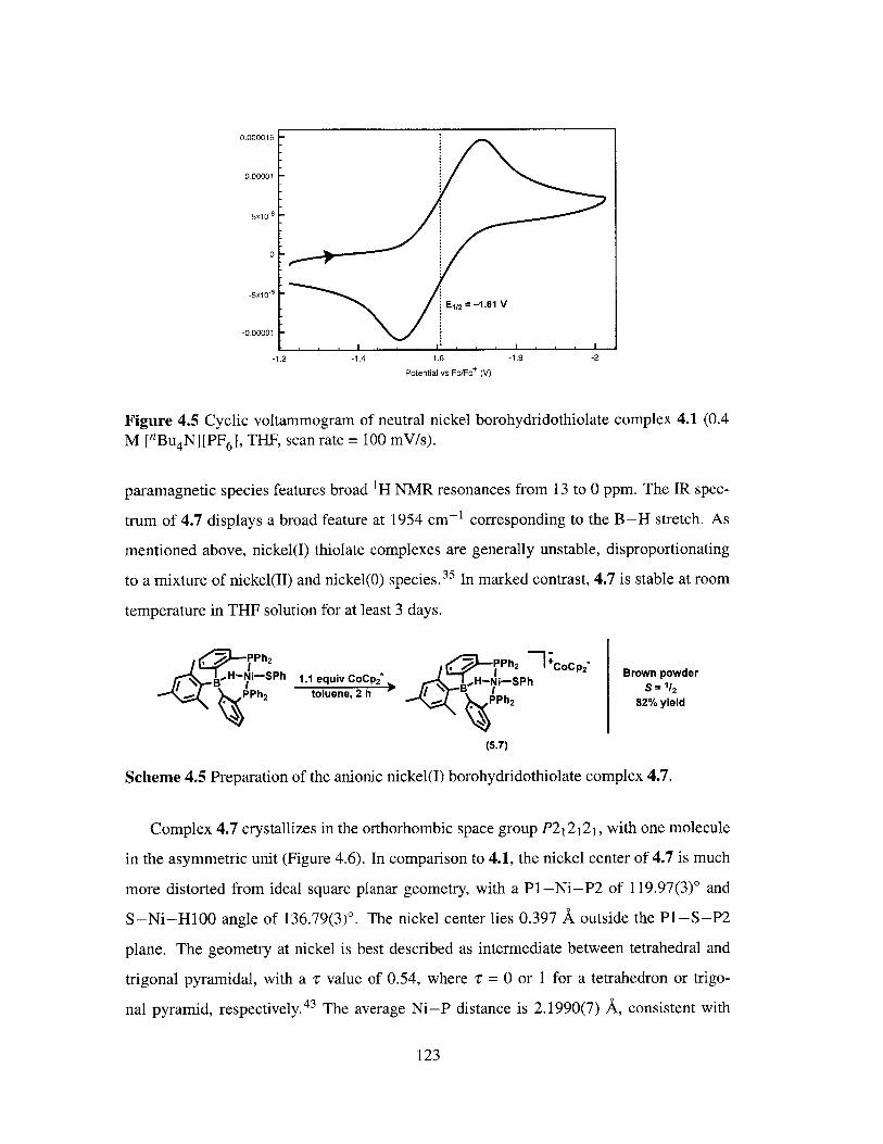
0.000015
0.00001
5x10⁻⁶
0
-5x10~6E1/2 =-1.61 V
-0.00001. I I .
-1.2 -1.4 -1.6 -1.8 -2
Potential vs Fc/Fc+ (V)
Figure 4.5 Cyclic voltammogram of neutral nickel borohydridothiolate complex 4.1 (0.4M ['Bu4N][PF 6], THF, scan rate = 100 mV/s).
paramagnetic species features broad 'H NMR resonances from 13 to 0 ppm. The IR spec-
trum of 4.7 displays a broad feature at 1954 cm-1 corresponding to the B-H stretch. As
mentioned above, nickel(I) thiolate complexes are generally unstable, disproportionating
to a mixture of nickel(II) and nickel(O) species. 35 In marked contrast, 4.7 is stable at room
temperature in THF solution for at least 3 days.
( PPh 2 Z PPh2 CoCp2
\Hi-SPh 1.1 equiv CoCp2* \BH--I- Brown powder4 B 1 oluee, 2h I '* BHIS S = 1/2
PPh2 toluene, 2 h PPh 2 82% yield
(5.7)
Scheme 4.5 Preparation of the anionic nickel(I) borohydridothiolate complex 4.7.
Complex 4.7 crystallizes in the orthorhombic space group P21212 1, with one molecule
in the asymmetric unit (Figure 4.6). In comparison to 4.1, the nickel center of 4.7 is much
more distorted from ideal square planar geometry, with a P1-Ni-P2 of 119.97(3)' and
S-Ni-H100 angle of 136.79(3)0. The nickel center lies 0.397 A outside the P1-S-P2
plane. The geometry at nickel is best described as intermediate between tetrahedral and
trigonal pyramidal, with a r value of 0.54, where r = 0 or 1 for a tetrahedron or trigo-
nal pyramid, respectively.43 The average Ni-P distance is 2.1990(7) A, consistent with
123

other structurally characterized, four-coordinate nickel(I) phosphine complexes (2.20 -
2.28 A).41'44 48 The Ni-S distance lengthens ca. 0.03 A (2.1782(3) A vs 2.2083(8) A)
and the Ni-S-C angle expands ca. 200 (99.77(3)0 vs 117.8(1)0) upon reduction of 4.1
to 4.7. Reported in 2009 by Tatsumi, Ni(S-2,6-dimesitylphenyl)(PPh 3) is the only other
structurally characterized example of a mononuclear nickel(i) thiolate complex. 4 9 In the
solid-state structure of Ni(S-2,6-dimesitylphenyl)(PPh3), the nickel is in a distorted square
planar geometry and is coordinated by PPh3 and the thiolate. There is also an 17-mesityl
interaction with one of the mesityl groups. The Ni-S distance is 2.2378(7) A and is ca.
0.03 A longer than that observed for 4.7.
p Selected Bond Lenaths (A) and AnalesflINi-P1 = 2.1927(7)NI-P2 = 2.2052(7)Ni-S = 2.2083(8)Ni-H100 = 1.50(1)
H100 S NI-B = 2.511(1)B-H100 = 1.36(2)
P2 P1-Ni-P2 = 160.16(1)S-NI-H100 = 165.1(6)
Figure 4.6 Solid-state structure of 4.7. Thermal ellipsoids are drawn at 40% probability.Counterion and hydrogen atoms except for the bridging borohydride (H100) are omittedfor clarity.
The X-band EPR spectrum of a dilute sample of 4.7, recorded in 2-MeTHF at 10 K, is
shown in Figure 4.7 (left). The EPR signal is rhombic, with g-values of 2.262, 2.245 an
1.995 (gis0 = 2.17). These values are consistent with other Ni(I) complexes having an S =
1/2 ground state with an unpaired electron occupying a predominantly d,2_y2 orbital. 5-58
The anisotropy of the g-values in the spectrum of 4.7 (Ag = 0.27) and the gis value of
2.17 indicate significant metalloradical character, as opposed to ligand radical character.
A single point energy calculation on 4.7 supports this interpretation, with a Mulliken spin
density of 0.83 on nickel, 0.13 on boron and 0.07 on sulfur. (Figure 4.7, right).
124

-Exp
I3S pin densty on Ni 0.83,2500 3000 3500 4000 P1 - -0.02, P2 = -0.02,
Magnetic Field (G) S = 0.07, B = 0.13, H = -0.05
Figure 4.7 (left) Experimental (black) and simulated (red) X-band EPR spectrum of 4.7 (2-MeTHF at 10 K). Simulated parameters: gi = 2.262, g2 = 2.245, g3 = 1.995; ag, = 0.045,
Ug 2 = 0.089, 1793 = 0.046. (right) Spin density surface calculated for 4.7 (DFr, Gaussian09, M06L/6-31 1+G(d,p), isovalue = 0.002).
4.5 Ni K-Edge XAS Studies
Seeking to gather more information about the unusual nickel(I) borohydridothiolate species
4.7, Ni K-edge XAS spectra were collected in collaboration with Professor Kyle Lancaster
(Cornell University). Figure 4.8 shows the normalized Ni K-edge XAS spectra obtained
for 4.1 and 4.7. The edge energy for the 4.1 spectrum is 8339.2(2) eV, which is similar
to other nickel(II) species bound to ligands containing one or two sulfur-donor atoms. 59-61
The intense pre-edge peak at 8334.9 eV is assigned to the 1s-+ 4pz transition and is charac-
teristic of four-coordinate planar nickel complexes. 61,62 Spectra obtained for planar nickel
complexes tend to exhibit a weak 1 s-+3d transition at ca. 8330 eV. However, combina-
tion of the weak ls-+3d absorption and the low edge energy associated with planar nickel
complexes with S-donor ligands frequently obscures the pre-edge peak attributed to this
transition.61 Accordingly, the Ni K-edge spectrum of 4.1 does not feature a resolved max-
imum for the ls-+3d transition. Upon reduction of 4.1 to 4.7, the edge energy shifts ca.
0.5 eV to 8338.7(2) eV. The pre-edge peak corresponding to the ls- 4 pz transition is di-
minished relative to that of 4.1, indicative of a deviation from a planar geometry toward a
non-planar configuration. 61,62 This geometric distortion is consistent with the changes ob-
served in the solid-state structures of 4.1 and 4.7 (vide supra). A very small shoulder at ca.
125

8332 eV is present in the spectrum of 4.7 that could correspond to the 1s-+3d transition,
however resolution of this peak is complicated by its proximity to the more intense, low
energy pre-edge feature. The Ni K-edge energy has been shown to vary systematically with
the charge residing on the nickel center.61-63 That the energy obtained for 4.7 is 0.5 eV less
than that measured for 4.1 indicates that the nickel center in 4.7 is more electron-rich than
in 4.1, consistent with the assignment of 4.7 as a formally nickel(I) borohydridothiolate
complex. 63
- Complex 4.11 --- Complex 4.7
0.8
C
0 . 0.8 -. -.
0.0
0.2 0
0 N
0.4
00
8325 8330 8335 8340 8345 8350
0
8200 8300 8400 8500 8600Energy (eV)
Figure 4.8 Normalized Ni K-edge XAS spectra obtained for 4.1 (solid line) and 4.7 (dashedline). The inset shows the edge region between 8325 and 8350 eV.
4.6 Conclusions and Future Work
In this chapter, the preparation of a series of nickel borohydridothiolate complexes by S--H
bond activation of arylthiols was described. Such species are rare; accordingly, there are
only two nickel hydride thiolate complexes characterized by X-ray crystallographic anal-
ysis reported in the literature. The complexes communicated in this chapter comprise the
only other examples of structurally characterized nickel hydride thiolate complexes. The
UV-vis spectra of the borohydridothiolate complexes each exhibit a charge transfer band
that shifts to slightly lower energy upon moving from electron-withdrawing to electron-
126

donating substituents in the para position of the thiolate ligand. This observation is consis-
tent with S-Ni (p)7r-(d)7r* character.
A formally nickel(I) borohydridothiolate complex was accessed by reduction of the
nickel(II) borohydridothiolate with CoCp*. The EPR spectrum of this anionic species is
consistent with an S = 1/2 ground state complex and an unpaired electron residing in the
dx2_ 2 orbital. Although a number of examples of nickel(I) thiolate complexes have been
prepared by in situ reduction, they are unstable to decomposition by comproportionation.
In marked contrast, the nickel(I) borohydridothiolate species described in this chapter is
isolable and is the second example of a structurally characterized nickel(I) thiolate com-
plex.
As EPR spectroscopy has been an important tool in the identification of odd-electron
enzyme intermediates, a logical advance would be the preparation of discrete nickel thio-
late complexes with odd-electron nickel(I) or nickel(III) oxidation states for comparison.
The nickel(I) borohydridothiolate complex described in this chapter is a rare example of
a well-defined nickel(I) thiolate species and, within the context of odd-electron enzymatic
intermediate characterization, would be of obvious interest to study in depth by various
spectroscopic techniques. Sulfur K-edge X-ray absorption spectroscopy (XAS) in partic-
ular will be an important experiment, as this technique is a direct probe of ligand-metal
bond covalency. 6 4 In addition to spectroscopic studies, the reactivity of the reduced nickel
thiolate complex with biologically relevant small molecule substrates should prove to be a
rich avenue of research, as the [MeSDPBPh]Ni core has a demonstrated ability to mediate
catalytic reactions (see Chapter 3).
4.7 Experimental Methods
4.7.1 General Considerations
All manipulations were carried out using standard Schlenk or glovebox techniques under a
dinitrogen atmosphere. Unless otherwise noted, solvents were dried and deoxygenated by
sparging with argon and passing through activated alumina in a solvent purification system
127

from SG Waters USA, LLC (Nashua, NH). Non-halogenated solvents were tested with a
standard purple solution of sodium benzophenone ketyl in tetrahydrofuran in order to con-
firm effective oxygen and moisture removal. 3.133 was prepared according to literature
methods. All other reagents were purchased from commercial suppliers and used with-
out further purification. Elemental analyses were performed by Midwest Microlab, LLC
(Indianapolis, IN) and Robertson Microlit Laboratories, Inc (Ledgewood, NJ). Deuterated
solvents were purchased from Cambridge Isotope Laboratories, Inc., degassed, and dried
over activated 3-A molecular sieves prior to use.
4.7.2 Spectroscopic Measurements
Varian 300, 400 and 500 MHz spectrometers were used to record 'H, 13 C, 3 1P and 11B
NMR spectra at room temperature, unless otherwise noted. 1H and 13C NMR chemical
shifts were referenced to the residual solvent peaks. 3 1P NMR chemical shifts were ref-
erenced to external 85% phosphoric acid (3 = 0 ppm). 11B NMR chemical shifts were
referenced to external BF 3 * Et20 (8 = 0 ppm). Optical spectroscopy measurements were
taken on a Cary 50 UV-vis spectrophotometer using a 1 cm two-window quartz cell sealed
with a closed cap (Starna Cells, Inc, Altascadero, CA). Infrared measurements were ob-
tained in thin films using a Bruker ALPHA FT-IR spectrometer equipped with a diamond
ATR probe and OPUS/Mentor software. X-band EPR spectra were recorded using a Bruker
EMX spectrometer at 77 K in 2-MeTHF glasses. EPR samples were prepared in a glovebox
under an N2 atmosphere in quartz EPR tubes equipped with J. Young caps. EPR spectra
were simulated using EasySpin. 65
4.7.3 Electrochemistry
Electrochemical measurements were carried out in a glovebox under a dinitrogen atmo-
sphere in a one-compartment cell using a CH Instruments 630-C Electrochemistry Ana-
lyzer with CHI Version 8.09 software package. A glassy carbon electrode and platinum
wire were used as the working and auxiliary electrodes, respectively. The reference elec-
trode was Ag/AgNO 3 in THF. Solutions of electrolyte (0.4 M ["Bu 4 N][PF 6]) and analyte
128

were prepared in a glovebox. Experiments were conducted at room temperature. The fer-
rocene couple Fc/Fc- was used as an external reference.
4.7.4 X-ray Spectroscopy
Ni K-edge XAS was measured at the Stanford Synchrotron Radiation Lightsource at beam
line 7-3 under ring conditions of 3 GeV and 500 mA. A Si(220) double-crystal monochro-
mator was used for energy selection and a Rh-coated mirror (set to an energy cutoff of
13 keV) was used for harmonic rejection. Internal energy calibration was performed by
assigning the first inflection point of a Ni foil spectrum to 8333 eV. Data were collected in
transmission mode (using N 2 -filled ionization chambers placed immediately up and down-
stream of the sample) on powdered samples suspended in boron nitride with the sample
maintained at 10 K in an Oxford liquid helium flow cryostat. Scans were averaged and pro-
cessed using the MAVE and PROCESS modules of the EXAFSPAK 66 software package.
4.7.5 DFT Calculations
Calculations for 4.7 were performed using the Gaussian09 suite of programs. 67 Single point
calculations were performed with the M06L functional 68 and the 6-311+G(d,p) basis set
for all atoms. The Mulliken spin densities calculated for 4.7 are summarized in Table 4.4.
Atom Value Atom Value
Ni 0.830088 P -0.015337
B 0.134412 P -0.018661
S 0.069245 - -
Table 4.4 Mulliken spin densities calculated for 4.7. For clarity, only the values for theheteroatoms are shown.
4.7.6 Preparation of [MesDPBPh](H)Ni(SPh) (4.1)
To a solution of 3.1 (42.4 mg, 59.6 Imol) in C6 H6 (1 mL) was added neat HSPh (7.8
pL, 76.3 ymol). The resulting green solution was stirred 6 h at room temperature, frozen
129
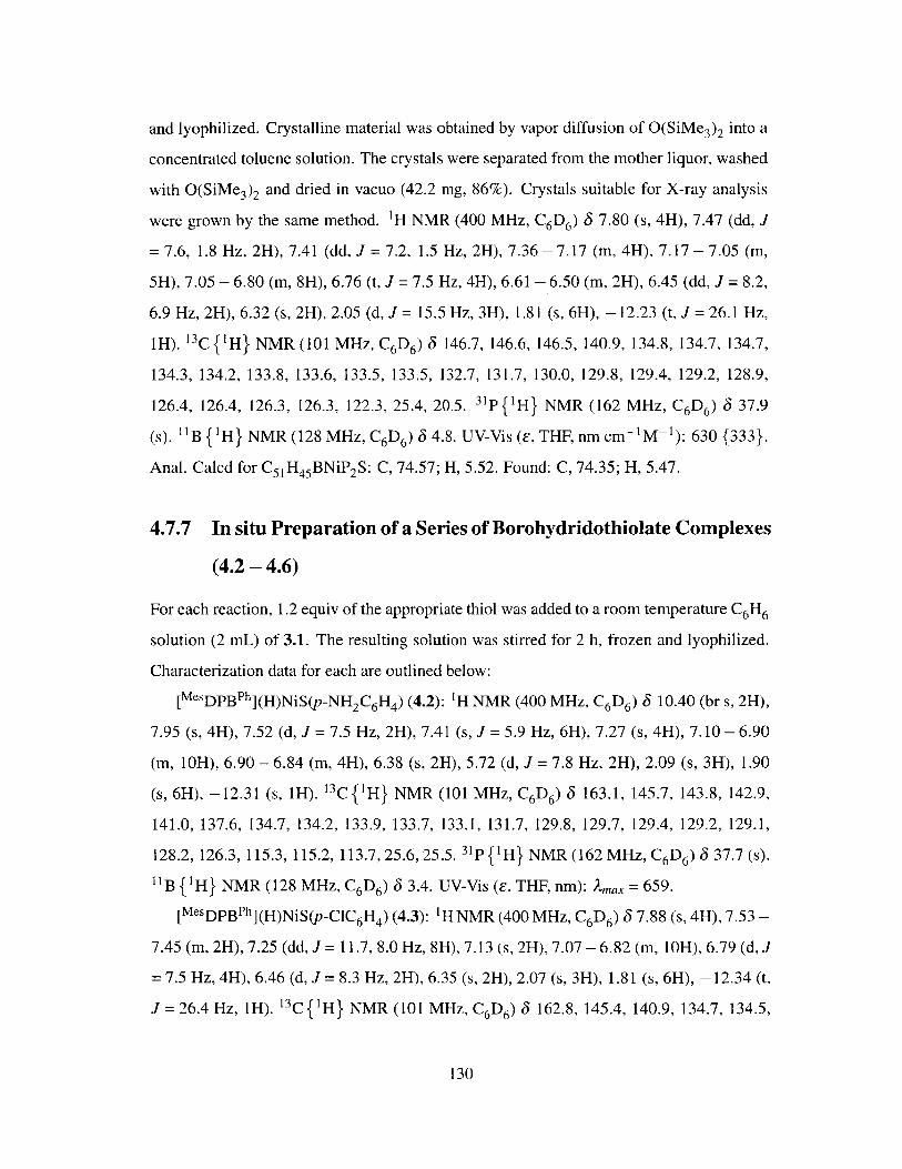
and lyophilized. Crystalline material was obtained by vapor diffusion of O(SiMe 3)2 into a
concentrated toluene solution. The crystals were separated from the mother liquor, washed
with O(SiMe3)2 and dried in vacuo (42.2 mg, 86%). Crystals suitable for X-ray analysis
were grown by the same method. 1H NMR (400 MHz, C6D6) 3 7.80 (s, 4H), 7.47 (dd, J
= 7.6, 1.8 Hz, 2H), 7.41 (dd, J = 7.2, 1.5 Hz, 2H), 7.36 - 7.17 (m, 4H), 7.17 - 7.05 (m,
5H), 7.05 - 6.80 (m, 8H), 6.76 (t, J = 7.5 Hz, 4H), 6.61 - 6.50 (m, 2H), 6.45 (dd, J = 8.2,
6.9 Hz, 2H), 6.32 (s, 2H), 2.05 (d, J = 15.5 Hz, 3H), 1.81 (s, 6H), -12.23 (t, J = 26.1 Hz,
1H). 13C {1 H} NMR (101 MHz, C6D6) 3 146.7, 146.6, 146.5, 140.9, 134.8, 134.7, 134.7,
134.3, 134.2, 133.8, 133.6, 133.5, 133.5, 132.7, 131.7, 130.0, 129.8, 129.4, 129.2, 128.9,
126.4, 126.4, 126.3, 126.3, 122.3, 25.4, 20.5. 31p 1H} NMR (162 MHz, C 6D6) 37.9
(s). 11B {' H} NMR (128 MHz, C6D6) 3 4.8. UV-Vis (E, THF, nm cm- 1 M- 1): 630 {333}.
Anal. Calcd for C5 1H4 5 BNiP 2 S: C, 74.57; H, 5.52. Found: C, 74.35; H, 5.47.
4.7.7 In situ Preparation of a Series of Borohydridothiolate Complexes
(4.2 - 4.6)
For each reaction, 1.2 equiv of the appropriate thiol was added to a room temperature C6H6
solution (2 mL) of 3.1. The resulting solution was stirred for 2 h, frozen and lyophilized.
Characterization data for each are outlined below:
[MesDPBPh](H)NiS(p-NH 2C6H4) (4.2): 'H NMR (400 MHz, C6 D6) 3 10.40 (br s, 2H),
7.95 (s, 4H), 7.52 (d, J = 7.5 Hz, 2H), 7.41 (s, J = 5.9 Hz, 6H), 7.27 (s, 4H), 7.10 - 6.90
(m, 10H), 6.90 - 6.84 (m, 4H), 6.38 (s, 2H), 5.72 (d, J = 7.8 Hz, 2H), 2.09 (s, 3H), 1.90
(s, 6H), -12.31 (s, 1H). 13 C {1H} NMR (101 MHz, C6D6) 3 163.1, 145.7, 143.8, 142.9,
141.0, 137.6, 134.7, 134.2, 133.9, 133.7, 133.1, 131.7, 129.8, 129.7, 129.4, 129.2, 129.1,
128.2, 126.3, 115.3, 115.2, 113.7,25.6,25.5. 31p {1H} NMR (162 MHz, C6D6) 3 37.7 (s).
"B { 1H} NMR (128 MHz, C6D6 ) 3 3.4. UV-Vis (E, THF, nm): Amax = 659.
[MesDPBPh](H)NiS(p-ClC 6H4) (4.3): 'H NMR (400 MHz, C6 D6 ) 8 7.88 (s, 4H), 7.53 -
7.45 (m, 2H), 7.25 (dd, J = 11.7, 8.0 Hz, 8H), 7.13 (s, 2H), 7.07 - 6.82 (m, IOH), 6.79 (d, J
= 7.5 Hz, 4H), 6.46 (d, J = 8.3 Hz, 2H), 6.35 (s, 2H), 2.07 (s, 3H), 1.81 (s, 6H), -12.34 (t,
J= 26.4 Hz, 1H). 13C{' H} NMR (101 MHz, C6D6) 3 162.8, 145.4, 140.9, 134.7, 134.5,
130

134.3, 134.1, 133.8, 133.7, 133.6, 133.5, 133.5, 131.6, 130.1, 130.0, 129.6, 129.3, 129.2,
128.4, 128.2, 128.1, 127.9, 127.7, 127.4, 126.5, 126.3, 126.2, 25.4, 20.6. 31p{1H} NMR
(162 MHz, C6D6) 6 38.4 (s). "B {'H} NMR (128 MHz, C6D6 ) 3 5.1. UV-Vis (E, C6H6,
nm): ,nax = 610.
[MesDPBPh](H)NiS(p-FC 6 H4 ) (4.4): X-ray quality crystals were grown by vapor diffu-
sion of O(SiMe 3 )2 into a concentrated toluene solution at -35 'C. IH NMR (400 MHz,
C6D6) 3 7.89 (s, 4H), 7.54 - 7.46 (m, 2H), 7.24 (dd, J = 8.4, 5.5 Hz, 8H), 7.13 (s, 1H),
7.06 - 6.90 (m, 9H), 6.90 - 6.73 (m, 6H), 6.36 (s, 2H), 6.19 (t, J = 8.7 Hz, 2H), 2.07 (s,
3H), 1.84 (s, 6H), -12.36 (t, J = 26.2 Hz, 1H). 13C {' H} NMR (75 MHz, C6D6 ) 3 162.7,
140.6, 134.2, 133.4, 133.3, 133.3, 133.2, 129.8, 129.7, 129.3, 129.0, 127.9, 127.9, 127.8,
127.7, 127.39, 127.2, 127.1, 126.2, 113.0, 112.7, 25.2, 20.3. 31p{'H} NMR (121 MHz,
C6D6) 3 39.3 (s). ' B { 'H} NMR (128 MHz, C6D6) 3 4.8. UV-Vis (e, C6H6 , nm): Amax =
615.
[MesDPBPh](H)NiS(p-CF 3C6H4) (4.5): 'H NMR (400 MHz, C6D6 ) 3 7.86 (s, 3H), 7.48
(s, 2H), 7.35 (s, 3H) 7.25 (s, 5H), 7.07 - 6.86 (m, 1OH), 6.76 (s, 7H), 6.64 (s, 3H), 6.35
(s, 2H), 2.06 (s, 3H), 1.81 (s, 5H), -12.23 (t, J = 26.3 Hz, 1H). 13C {'H} NMR (75 MHz,
C6D6 ) 3 163.3, 141.5, 136.1, 135.1, 134.8, 133.5, 133.2, 131.8, 131.5, 129.6, 129.3, 127.2,
124.2, 25.3, 21.74. 3 1p{1H} NMR (121 MHz, C6D6 ) 3 40.8 (s). '9F{1H} NMR (376
MHz, C616) -61.0. "B {'H} NMR (128 MHz, C6D6) 3 5.8. UV-Vis (E, C6H6, ni):
)Lmax = 600.
[MesDPBPh](H)NiS(p-OMeC 6 H4 ) (4.6): X-ray quality crystals were grown by vapor
diffusion of O(SiMe3 )2 into a concentrated toluene solution at -35 'C. 1H NMR (400
MHz, C6D6 ) 3 7.94 (s, 4H), 7.57 - 7.48 (m, 2H), 7.37 (d, J = 6.4 Hz, 4H), 7.32 - 7.23
(m, 4H), 7.14 - 7.10 (m, 2H), 7.06 - 6.86 (m, 1OH), 6.83 (t, J = 7.5 Hz, 4H), 6.37 (s, 2H),
6.14 (d, J = 8.6 Hz, 2H), 3.16 (s, 3H), 2.08 (s, 3H), 1.89 (s, 6H), -12.29 (t, J = 26.2 Hz,
1H). 3C { 'H} NMR (101 MHz, C6D6) 3 156.6, 140.9, 136.6, 134.7, 134.4, 134.3, 133.8,
131.7, 129.9, 129.8, 129.5, 129.2, 129.1, 128.2, 128.0, 128.0, 127.9, 127.7, 127.5, 127.4,
126.3, 112.5, 112.4, 54.4, 54.4, 25.5, 20.6, 20.5. 31p {1 H} NMR (162 MHz, C6D6 ) 3 37.9
(s). "B {'H} NMR (128 MHz, C6D6) 8 4.9. UV-Vis (e, C6 H6 , nm): Amax = 635.
131

4.7.8 Preparation of [[MesDPBPh](H)Ni(SPh)][CoCp*] (4.7)
To a solution of 4.1 (69.9 mg, 85.10 pmol) in toluene (1 mL) was added a toluene slurry
of CoCp* (28.1 mg, 85.31 ymol). The resulting brown slurry was stirred for 4 hr at room
temperature and then filtered to collect the brown solids. The solids were dissolved in THF
and filtered through Celite to remove a small amount of black solids. Crystalline material
was obtained by vapor diffusion of pentane into a concentrated THF solution. The crystals
were separated from the mother liquor, washed with pentane and dried in vacuo (80.3 mg,
82%). Crystals suitable for X-ray analysis were grown by the same method. 1H NMR (400
MHz, THF-d8) 3 11.9, 10.0, 7.5, 5.9, 2.1, 1.2. Anal. Calcd for C7 1 H75BCoNiP 2 S .2 THF:
C, 73.27; H, 7.08. Found: C, 72.76; H, 6.75. IR (ATR, THF film, cm- 1 ): 1954.
4.7.9 X-ray Crystallographic Details
Single crystals of 4.1, 4.4 and 4.6 were obtained by vapor diffusion of O(SiMe 3)2 into a
concentrated toluene solution either at room temperature or -35 'C, crystals of 4.7 were
grown by vapor diffusion of pentane into a concentrated THF solution. Low-temperature
single crystal X-ray diffraction studies were carried out at the Beckman Institute Crystal-
lography Facility on a Bruker Kappa Apex II diffractometer with Mo Ka radiation (A =
0.71073 A). Crystals were coated with Paratone-N oil and mounted on glass fibers. Struc-
tures were solved by direct or Patterson methods using SHELXS 69 and refined against
F2 on all data by full-matrix least squares with SHELXL-97 70 using established refine-
ment techniques. 71 All non-hydrogen atoms were refined anisotropically. All hydrogen
atoms (except the hydrogen atoms bound to heteroatoms in 4.1 - 4.7) were included into
the model at geometrically calculated positions and refined using a riding model. The
isotropic displacement parameters of all calculated hydrogen atoms were fixed to 1.2 times
the U values of the atoms they are linked to (1.5 times for methyl groups). Thermal ellip-
soid diagrams were created using Olex2. 72 In the structure of 4.6, there is a disordered half
molecule of toluene. The crystallographic details for 4.1 - 4.7 are summarized in Tables 4.5
and 4.6.
132
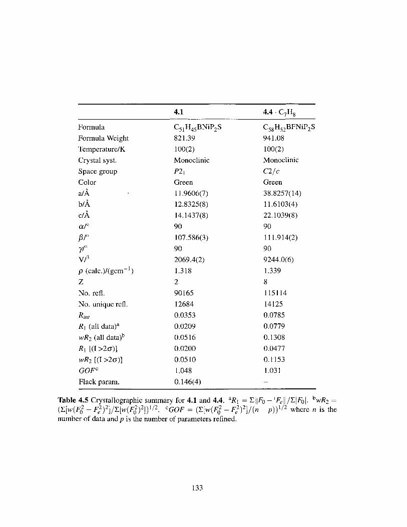
4.1
Formula
Formula Weight
Temperature/K
Crystal syst.
Space group
Color
a/A-
b/A
c/A
a/'
#/Oy/0V/1
p (calc.)/(gcm-
zNo. refl.
1)
No. unique refl.
Rin,
R, (all data)a
wR 2 (all data)b
R, [(I >2a)]
wR 2 [(I >2(a)]
GOFc
Flack param.
C5 1H4 5BNiP 2 S821.39
100(2)
Monoclinic
P21
Green
11.9606(7)
12.8325(8)
14.1437(8)
90
107.586(3)
90
2069.4(2)
1.318
2
90165
12684
0.0353
0.0209
0.0516
0.0200
0.0510
1.048
0.146(4)
4.4 -C7H8
C 58 H52 BFNiP 2 S
941.08
100(2)
Monoclinic
C2/c
Green
38.8257(14)
11.6103(4)
22.1039(8)
90
111.914(2)
90
9244.0(6)
1.339
8
115114
14125
0.0785
0.0779
0.1308
0.0477
0.1153
1.031
Table 4.5 Crystallographic summary for 4.1 and 4.4. aR 1 = EIIFo - IFe /EFol. bwR 2 =
(y[w(F2 - F2)2]/[w(F2)2])1/ 2. cGOF = ([w(F 2 - )2]/(n - P))1/ 2 where n is thenumber of data and p is the number of parameters refined.
133
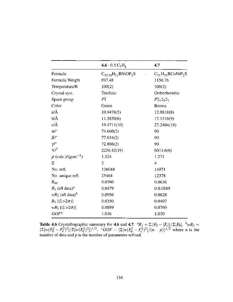
4.6. 0.5 C7H84.7
Formula
Formula Weight
Temperature/K
Crystal syst.
Space group
Color
a/A
b/A
c/A
a/0
#/0y/0V/3
p (calc.)/(gcm-
zNo. refi.
No. unique refl.
Rint
RI (all data)a
wR2 (all data)b
R, [(I >2a)]
wR2 [(I >2u)]
GOFc
C55.50H51BNiOP 2S
897.48
100(2)
Triclinic
P!
Green
10.9476(5)
11.5830(6)
19.4711(10)
74.660(2)
77.634(2)
72.866(2)
2250.42(19)
1.324
2
126044
25464
0.0380
0.0479
0.0956
0.0350
0.0889
1.036
1)
C71 H75BCoNiP 2S
1150.76
100(2)
Orthorhombic
P212121
Brown
12.8818(8)
17.1316(9)
27.2404(19)
90
90
90
6011.6(6)
1.271
4
14971
12378
0.0636
0.0.0589
0.0828
0.0407
0.0760
1.020
Table 4.6 Crystallographic summary for 4.6 and 4.7. 'R 1 = EIIF - FeII/EIFoI. 'wR2 =
(y[w(F2 - F) 2 ]/ w(F) 2])/ 2. cGOF = ([w(F2 - F2)2](n - p))l / 2 where n is thenumber of data and p is the number of parameters refined.
134
4.6 - 0.5 C7H8 4.7
4.8 Bibliography
[1] Malyshev, D. A.; Scott, N. M.; Marion, N.; Stevens, E. D.; Ananikov, V. P.; Belet-
skaya, I. P.; Nolan, S. P. Organometallics 2006, 25, 4462-4470.
[2] Back, T. G.; Krishna, M. V. J. Org. Chem. 1988, 53, 2533-2536.
[3] Ichinose, Y.; Wakamatsu, K.; Nozaki, K.; Birbaum, J.-L.; Oshima, K.; Utimoto, K.
Chem. Lett. 1987, 1647-1650.
[4] Griesbaum, K. Angew. Chem. Int. Ed. 1970, 9, 273-287.
[5] Truce, W. E.; Heine, R. F. J. Am. Chem. Soc. 1957, 79, 5311-5313.
[6] Truce, W. E.; Simms, J. A. J. Am. Chem. Soc. 1956, 78, 2756-2759.
[7] Metzner, P.; Thuiller, A. Sulfur Reagents in Organic Synthesis; Academic Press:
London, 1994.
[8] Zwanenburg, B., Klunder, A. J. H., Eds. Perspectives in the Organic Chemistry of
Sulfur; Elsevier: Amsterdam, 1987.
[9] Beller, M.; Seayad, J.; Tillack, A.; Jiao, H. Angew. Chem. Int. Ed. 2004, 43, 3368-3398.
[10] Alonso, F.; Beletskaya, I. P.; Yus, M. Chem. Rev. 2004, 104, 3079-3159.
[11] Ogawa, A. J. Organomet. Chem. 2000, 611, 463-474.
[12] Kondo, T.; Mitsudo, T. Chem. Rev. 2000, 100, 3205-3220.
[13] Castarlenas, R.; Di Giuseppe, A.; Pdrez-Torrente, J. J.; Oro, L. A. Angew. Chem. Int.
Ed. 2013, 52, 211-222.
[14] Ogawa, A.; Ikeda, T.; Kimura, K.; Hirao, T. J. Am. Chem. Soc. 1999, 121, 5108-5114.
[15] Kuniyasu, H.; Ogawa, A.; Sato, K.-I.; Ryu, I.; Kambe, N.; Sonoda, N. J. Am. Chem.Soc.1992,114,5902-5903.
[16] Ananikov, V. P.; Orlov, N. V.; Beletskaya, I. P.; Khrustalev, V. N.; Antipin, M. Y.;
Timofeeva, T. V. J. Am. Chem. Soc. 2007, 129, 7252-7253.
[17] Ananikov, V. P.; Orlov, N. V.; Beletskaya, I. P. Organometallics 2006, 25, 1970-1977.
[18] Ananikov, V. P.; Malyshev, D. A.; Beletskaya, I. P.; Aleksandrov, G. G.; Ere-
menko, I. L. Adv. Synth. Catal. 2005, 347, 1993-2001.
[19] Di Giuseppe, A.; Castarlenas, R.; Perez-Torrente, J. J.; Crucianelli, M.; Polo, V.;
Sancho, R.; Lahoz, F. J.; Oro, L. A. J. Am. Chem. Soc. 2012, 134, 8171-8183.
135

[20] Shoai, S.; Bichler, P.; Kang, B.; Buckley, H.; Love, J. A. Organometallics 2007, 26,5778-5781.
[21] Cao, C.; Fraser, L. R.; Love, J. A. J. Am. Chem. Soc. 2005, 127, 17614-17615.
[22] Ragsdale, S. W. J. Biol. Chem. 2009, 284, 18571-18575.
[23] Sigel, A., Sigel, H., Sigel, R. K. 0., Eds. Nickel and Its Surprising Impact in Nature;John Wiley & Sons, Ltd: Chichester, UK, 2007; Vol. 2.
[24] Barondeau, D. P.; Kassmann, C. J.; Bruns, C. K.; Tainer, J. A.; Getzoff, E. D. Bio-chemistry 2004, 43, 8038-8047.
[25] Vignais, P. M.; Billoud, B. Chem. Rev. 2007, 107, 4206-4272.
[26] Ragsdale, S. W.; Pierce, E. Biochim. Biophys. Acta 2008, 1784, 1873-1898.
[27] Dobbek, H.; Svetlitchnyi, V.; Gremer, L.; Huber, R.; Meyer, 0. Science 2001, 293,1281-1285.
[28] Doukov, T. I.; Blasiak, L. C.; Seravalli, J.; Ragsdale, S. W.; Drennan, C. L. Biochem-istry 2008, 47, 3474-3483.
[29] Doukov, T. I.; Iverson, T. M.; Seravalli, J.; Ragsdale, S. W.; Drennan, C. L. Science2002, 298, 567-572.
[30] Bouwman, E.; Reedijk, J. Coord. Chem. Rev. 2005, 249, 1555-1581.
[31] Evans, D. J. Coord. Chem. Rev. 2005,249, 1582-1595.
[32] Harrop, T. C.; Mascharak, P. K. Coord. Chem. Rev. 2005, 249, 3007-3024.
[33] Harman, W. H.; Peters, J. C. J. Am. Chem. Soc. 2012, 134, 5080-5082.
[34] Schaub, T.; Backes, M.; Plietzsch, 0.; Radius, U. Dalton Trans. 2009, 7071-7079.
[35] Nag, K.; Chakravorty, A. Coord. Chem. Rev. 1980, 33, 87-147.
[36] Ge, P.; Riordan, C. G.; Yap, G. P.; Rheingold, A. L. Inorg. Chem. 1996, 35, 5408-5409.
[37] Kruger, H. J.; Holm, R. H. Inorg. Chem. 1989, 28, 1148-1155.
[38] Kim, J. S.; Reibenspies, J. H.; Darensbourg, M. Y J. Am. Chem. Soc. 1996, 118,4115-4123.
[39] Pereira, E.; Gomes, L.; de Castro, B. Inorg. Chim. Acta 1998, 271, 83-92.
[40] Rosen, W.; Busch, D. H. J. Am. Chem. Soc. 1969, 91, 4694-4697.
[41] MacBeth, C. E.; Thomas, J. C.; Betley, T. A.; Peters, J. C. Inorg. Chem. 2004, 43,4645-4662.
136

[42] Gennari, M.; Orio, M.; Pecaut, J.; Bothe, E.; Neese, F.; Collomb, M.-N.; Duboc, C.Inorg. Chem. 2011, 50, 3707-3716.
[43] Addison, A. W.; Rao, T. N.; Reedijk, J.; van Rijn, J.; Verschoor, G. C. J. Chem. Soc.,Dalton Trans. 1984, 1349-1356.
[44] Beck, R.; Shoshani, M.; Krasinkiewicz, J.; Hatnean, J. A.; Johnson, S. A. Dalton
Trans. 2013, 42, 1461-1475.
[45] Mindiola, D. J.; Hillhouse, G. L. J. Am. Chem. Soc. 2001, 123, 4623-4624.
[46] Bianchini, C.; Masi, D.; Mealli, C.; Meli, A. Cryst. Struct. Commun. 1982, 11,1475-1480.
[47] Gleizes, A.; Dartiguenave, M.; Dartiguenave, Y; Galy, J.; Klein, H. F. J Am. Chem.
Soc.1977,99,5187-5189.
[48] Dapporto, P.; Fallani, G.; Sacconi, L. Inorg. Chem. 1974, 13, 2847-2850.
[49] Ito, M.; Matsumoto, T.; Tatsumi, K. Inorg. Chem. 2009, 48, 2215-2223.
[50] Saraev, V. V.; Kraikivskii, P. B.; Matveev, D. A.; Kuzakov, A. S.; Vilms, A. I.;Fedonina, A. A. Russ. J. Coord. Chem. 2008, 34, 438-442.
[51] Saraev, V. V.; Kraikivskii, P. B.; Vilms, A. I.; Zelinskii, S. N.; Yunda, A. Y.; Danilovt-seva, E. N.; Kuzakov, A. S. Kinet. Catal. 2007, 48, 778-784.
[52] Suh, M. P.; Oh, K. Y.; Lee, J. W.; Bae, Y Y. J. Am. Chem. Soc. 1996, 118, 777-783.
[53] Bowmaker, G. A.; Williams, J. P. J. Chem. Soc., Dalton Trans. 1994, 1231-1236.
[54] Bowmaker, G. A.; Williams, J. P. J. Chem. Soc., Dalton Trans. 1993, 3593-3600.
[55] Suh, M. P.; Kim, H. K.; Kim, M. J.; Oh, K. Y. Inorg. Chem. 1992, 31, 3620-3625.
[56] Chmielewski, P.; Grzeszczuk, M.; Latos-Grazyniski, L.; Lisowski, J. Inorg. Chem.1989, 28, 3546-3552.
[57] Stolzenberg, A. M.; Stershic, M. T. Inorg. Chem. 1987, 26, 3082-3083.
[58] Gagne, R. R.; Ingle, D. M. Inorg. Chem. 1981, 20, 420-425.
[59] Gu, Z.; Dong, J.; Allan, C. B.; Choudhury, S. B.; Franco, R.; Moura, J. J. G.;Moura, I.; LeGall, J.; Przybyla, A. E.; Roseboom, W.; Albracht, S. P. J.; Mil-ton, J. A.; Scott, R. A.; Maroney, M. J. J. Am. Chem. Soc. 1996, 118, 11155-11165.
[60] Bagyinka, C.; Whitehead, J. P.; Maroney, M. J. J. Am. Chem. Soc. 1993, 115, 3576-3585.
[61] Colpas, G. J.; Maroney, M. J.; Bagyinka, C.; Kumar, M.; Willis, W. S.; Suib, S. L.;Baidya, N.; Mascharak, P. K. Inorg. Chem. 1991, 30, 920-928.
137

[62] Furenlid, L. R.; Renner, M. W.; Fujita, E. Phys. B 1995, 208, 739-742.
[63] Tang, Q.; Carrington, P. E.; Horng, Y.-C.; Maroney, M. J.; Ragsdale, S. W.; Bo-cian, D. F. J. Am. Chem. Soc. 2002, 124, 13242-13256.
[64] Glaser, T.; Hedman, B.; Hodgson, K. 0.; Solomon, E. I. Acc. Chem. Res. 2000, 33,859-868.
[65] Stoll, S.; Schweiger, A. J. Magn. Reson. 2006, 178, 42-55.
[66] George, G. N. EXAFSPAK. Stanford Synchrotron Radiation Laboratory, Stanford
Linear Accelerator Center, Stanford University.
[67] Frisch, M. J. et al. Gaussian 09, Revision B.01. Gaussian, Inc., Wallingford, CT,2010.
[68] Zhao, Y.; Truhlar, D. G. Theor Chem. Acc. 2008, 120, 215-241.
[69] Sheldrick, G. M. Acta Cryst. 1990, A46, 467-473.
[70] Sheldrick, G. M. SHELXL-97: Program for Crystal Structure Refinement. Univer-
sity of G6ttingen, G6ttingen, Germany, 1997.
[71] Mlller, P. Crystallogr. Rev. 2009, 15, 57-83.
[72] Dolomanov, 0. V.; Bourhis, L. J.; Gildea, R. J.; Howard, J. A. K.; Puschmann, H. J.
Appl. Cryst. 2009, 42, 339-341.
138

Preparation of Low-Valent Iron
Complexes Supported by
Tris(phosphine)borate and
Bis(phosphine)borate Ligands
Introduction . . . . . . . . . . . . . . . . . . . . . . . . . . . . . . .
[PhBP h]FeMe: Isolation of an Elusive Species . . . . . . . . . . . .
Hydrogenation Studies Employing [PhBP h]FeMe . . . . . . . . . .
Accessing the Iron Chemistry of Bis(phosphine)borate Ligands . . .
Preparation of Bis(phosphine)borate Anilido and Aryloxide Com-
plexes . . . . . . . . . . . . . . . . . . . . . . . . . . . . . . . . . . .
Preparation of Bis(phosphine)borate Alkyl Complexes . . . . . . . .
Pitfalls of the [Ph 2BPR]Fe Systems . . . . . . . . . . . . . . . . . . .
Conclusions and Future Work . . . . . . . . . . . . . . . . . . . . .
Experimental Methods . . . . . . . . . . . . . . . . . . . . . . . . .
5.9.1 General Considerations . . . . . . . . . . . . . . . . . . . . . .
5.9.2 Spectroscopic Measurements . . . . . . . . . . . . . . . . . . .
5.9.3 Electrochemistry . . . . . . . . . . . . . . . . . . . . . . . . .
139
5
Contents
5.1
5.2
5.3
5.4
5.5
5.6
5.7
5.8
5.9
140
143
145
151
156
159
161
163
164
164
165
165
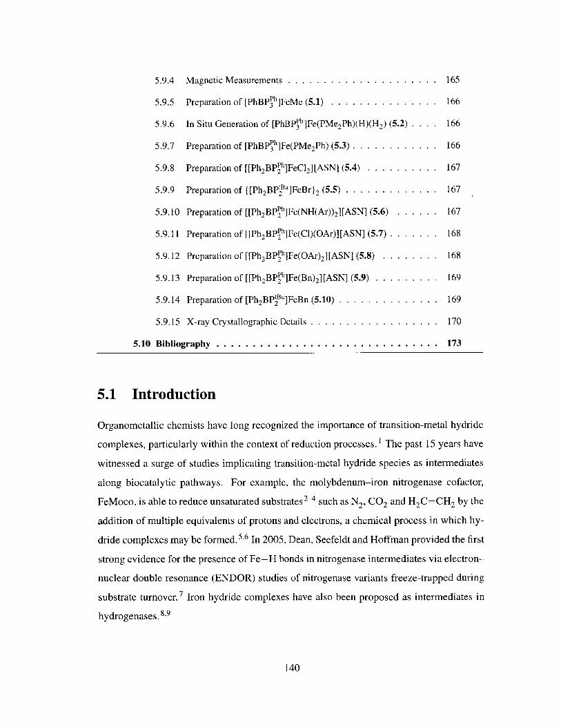
5.9.4 Magnetic Measurements .1
5.9.5 Preparation of [PhBP h]FeMe (5.1) . . . . . . . . . . . . . . . 166
5.9.6 In Situ Generation of [PhBPh]Fe(PMe 2Ph)(H)(H 2) (5.2) . . . . 166
5.9.7 Preparation of [PhBPPh]Fe(PMe 2Ph) (5.3) . . . . . . . . . . . . 166
5.9.8 Preparation of [[Ph 2BPh]FeCl 2][ASN] (5.4) . . . . . . . . . . 167
5.9.9 Preparation of {[Ph 2BPtu]FeBr}2 (5.5) . . . . . . . . . . . . . 167
5.9.10 Preparation of [[Ph 2 BP h]Fe(NH(Ar)) 2][ASN] (5.6) . . . . . . 167
5.9.11 Preparation of [[Ph2 BPPh]Fe(Cl)(OAr)][ASN] (5.7) . . . . . . . 168
5.9.12 Preparation of [[Ph2 BP h]Fe(OAr) 2][ASN] (5.8) . . . . . . . . 168
5.9.13 Preparation of [[Ph2 BPPh]Fe(Bn) 2][ASN] (5.9) . . . . . . . . . 169
5.9.14 Preparation of [Ph 2 BPtu]FeBn (5.10) . . . . . . . . . . . . . . 169
5.9.15 X-ray Crystallographic Details . . . . . . . . . . . . . . . . . . 170
5.10 Bibliography ..................................... 173
5.1 Introduction
Organometallic chemists have long recognized the importance of transition-metal hydride
complexes, particularly within the context of reduction processes.1 The past 15 years have
witnessed a surge of studies implicating transition-metal hydride species as intermediates
along biocatalytic pathways. For example, the molybdenum-iron nitrogenase cofactor,
FeMoco, is able to reduce unsaturated substrates2-4 such as N2 , CO2 and H 2 C=CH2 by the
addition of multiple equivalents of protons and electrons, a chemical process in which hy-
dride complexes may be formed.5,6 In 2005, Dean, Seefeldt and Hoffman provided the first
strong evidence for the presence of Fe-H bonds in nitrogenase intermediates via electron-
nuclear double resonance (ENDOR) studies of nitrogenase variants freeze-trapped during
substrate turnover.7 Iron hydride complexes have also been proposed as intermediates in
hydrogenases. 8 ,9
140
. . . . . . . . . 165

Although their preparation is a burgeoning area of research, 1 0 there are surprisingly
few examples of well-defined synthetic iron hydride complexes that are reported to cat-
alytically reduce olefins under ambient temperature and pressure. 1 ' Moreover, although
paramagnetic hydride species have been proposed as catalytic intermediates of hydroge-
nase and nitrogenase enzymes, the majority of synthetic transition metal hydride complexes
are diamagnetic, closed-shell species. Iron pentacarbonyl is able to hydrogenate 1-hexene,
however temperatures in excess of 200 'C and pressures between 200 and 250 atm are re-
quired for catalytic activity. 12,13 Wrighton subsequently developed a photocatalytic method
for olefin hydrogenation using iron pentacarbonyl that operates efficiently at room temper-
ature and ambient pressure; to achieve catalytic turnover, however, continuous irradiation
with 366 nm light was required. 14,15 It was not until 1992 that Bianchini demonstrated the
catalytic reduction of alkynes to alkenes under mild conditions (20 'C, 1 atm H 2) using the
well-defined, cationic complex [[PP 3]Fe(H)(L)][BPh 4] ([PP 3] = P(CH2 CH2 PPh2) 3 , L = N2
or H2) 16 Despite this success, further conversion of alkenes to alkanes by the Bianchini
system was not observed. Holland recently provided examples of dimeric iron(II) hydride
and monomeric iron(I) hydride complexes supported by bulky $-diketiminate ligands. 17,18
The reactivity of these complexes with olefins is largely unexplored. The dimeric hydride
complexes react with olefins to give iron(II) alkyl species, but no further chemistry was
pursued. 18
In 2004, Chirik and Peters independently reported structurally distinct, well-defined
iron complexes capable of catalytically hydrogenating unsaturated hydrocarbon substrates
under relatively mild conditions (Figure 5.1). The pyridinediimine (PDI) precatalyst re-
ported by Chirik is particularly active, hydrogenating 1-hexene under 4 atm of H2 at room
temperature with catalyst loadings as low as 0.3 mol %. 19 Notably, this iron system out-
performs precious metal catalysts under these conditions, reaching a turnover frequency
(TOF) of 1814 h-' compared to 366 h-1 for 10% Pd/C, 10 h-' for (PPh 3)3RhCl and 75
h-1 for [(cod)Ir(PCy 3 )(py)]I[PF 6 ]. Mechanistic investigations on the pyridinediimine sys-
tem suggest a catalytic cycle in which both N 2 ligands are lost, forming an unsaturated
14-electron iron(0) pyridinediimine complex that coordinates olefin. Subsequent oxidative
addition of H 2 and insertion of the olefin into the iron(II) hydride bond yields the corre-
141

sponding iron(II) alkyl complex. Reductive elimination of alkane regenerates the starting
low-valent fragment. Although this mechanistic proposal was not formally disclosed, sub-
sequent studies of C-C bond forming reactions catalyzed by the iron PDI complex suggest
that the PDI ligand is redox noninnocent and that the iron(II) oxidation state is maintained
throughout catalysis. 20
CH3
I Pr Fe irPrrChirik N $Pr **Pr Peters
Ij (NO 'Pr0.3 mol %, 12 min N F N 10 mol %, 115 min
TOF = 1814 h- 1 Ar Ar B TOF = 5.2 h-1
N2 N2
Figure 5.1 Iron precatalysts reported by (left) Chirik and (right) Peters. Both species are
active for the hydrogenation of 1-hexene under mild conditions, with TOFs of 1814 and 5.2
h- 1 , respectively.
The 14-electron tris(phosphine)borate complex, [PhBP'pr]FeMe, reported by Peters is
much less active than the Chirik system, reaching a TOF of only 5.2 h-' at 10 mol % cat-
alyst loading. However, this provided the opportunity to directly observe several plausible
intermediates relevant to the overall catalytic hydrogenation cycle. 21 This system likely
proceeds through an iron(II)/iron(IV) redox cycle in which H2 addition to the iron(II)
methyl complex generates an iron(IV) trihydride complex and one equivalent of methane.
Loss of H2 and concomitant olefin binding via an unobserved, four-coordinate iron(II) hy-
dride complex, followed by olefin insertion into the Fe-H bond gives the corresponding
iron(II) alkyl complex. This species goes on to react with H2 to release alkane and regen-
erate the iron(IV) trihydride species.
Another report of relevance to the hydrogenation chemistry described by Peters is the
observation that, in the presence of excess H2 , the Fe-N bond of the iron(III) imido
complex [PhBPPh]Fe=NAr (Ar = p-tolyl) is cleaved, generating p-tolylamine and a re-
active, unobserved iron(II) hydride species. 22 In the presence of C6H6, insertion into the
iron hydride bond occurs, slowly forming a stable iron(II) i7-cyclohexadienyl species, as
shown in Scheme 5.1. Motivated by these results, we sought to extend the hydrogenation
chemistry to the [PhBPh] system in hopes of accessing other intermediates along the hy-
142

drogenation pathway by virtue of the less electron-donating character of the phosphines
relative to [PhBPir]. The Peters group has previously shown that the reactivity patterns
of [PhBPPh]Fe and [PhBPi'r]Fe can be considerably different. 23 Described in this chap-
ter are efforts toward that end and an exploration of the coordination chemistry of iron
bis(phosphine)borate complexes in an attempt to generate a more active precatalyst for
olefin hydrogenation.
ArNIII
Ph F e H HHPh H~Pe p ANH I atm H2 1AM
?)'i Ph NH H C6H6 '"'k..B I
C6H6 Fe RT,cdays Fe IRT, hours [PhBP3Ph] - H2NAr [PhBP3Ph ] Fe
[PhBP32"][PhBP3Ph]FeNAr Unobserved
Ar = p-tolyl
Scheme 5.1 Hydrogenolysis of [PhBpPh]Fe=-NAr. The purported iron(II) benzene adduct
is not experimentally observed.
5.2 [PhBPph]FeMe: Isolation of an Elusive Species
For the [PhBPir] system described above, the room temperature hydrogenation of a se-
ries of iron alkyl complexes gives access to the hydrogenation reactions of interest. 21 Al-
though it would be attractive to employ similar methods to the [PhBPh] system, syn-
thetic challenges have hampered isolation of [PhBPPh]FeR complexes. For example, treat-
ment of [PhBPir]FeC1 with Grignard or alkyllithium reagents provides the correspond-
ing [PhBPI'r]FeR species; the analogous reactions with [PhBPPh]FeCl result in intractable
black solids and the formation of free PMePh2 as a result of B-Calkyl bond cleavage
(Scheme 5.2, left). Overreduction of the metal center was avoided by treatment of a C6H6
slurry of [PhBpPh]FeCl with 10 equiv of Me2 Mg (Scheme 5.2, right). In C6H6, Me 2Mg
is sparingly soluble, thereby minimizing the potential for deleterious side-reactions and al-
lowing for facile separation of the product, MgCl 2 and unreacted Me 2Mg. After 2 h, the
14-electron complex [PhBPh ]FeMe (5.1) was isolated as an amber powder in ca. 90%
yield.
Complex 5.1 is paramagnetic, with broad resonances in its 1H NMR spectrum rang-
143

C MeI I
Fe0, PMePh 2 Pht FPh PhPh .PPh
and other MeLi or MeMgBr or Pr Ph 10 equiv Me2Mg Ph Ph S=2
unidentified LiCH2SiMe3 or BnMgCI B C6H, 2 h B 93% yieldspecies 6
(5.1)
Scheme 5.2 (left) Treatment of [PhBPh]FeCl with alkyllithium and Grignard reagentsleads to overreduction of the metal center. (right) Overreduction can be avoided usingMe 2 Mg.
ing from 50 to - 110 ppm. The Evans method solution magnetic moment (perr = 5.0 pB,
C6D 6, 25 C) indicates an S = 2 ground state and is consistent with that observed for
[PhBPfr]FeMe. Complex 5.1 crystallizes in the monoclinic space group C2/c, with one
molecule in the asymmetric unit (Figure 5.2). The geometry at iron is best described as
pseudotetrahedral, with an average P-Fe-P angle of 90.79(2)'. The Fe-P distances are
slightly asymmetric (2.4089(6), 2.4330(6) and 2.4350(6) A), however their average (2.4256
A) is consistent with other mononuclear, high-spin [PhBP h]FeX complexes (2.34 - 2.452
A).22,24 The P-Fe-C46 angles are also distorted (B. .. Fe-C46 = 175.880); this obser-
vation can be attributed in part to the steric demands of the [PhBP h] ligand. Five of the
six phosphorus-bound phenyl groups lie perpendicular to the P 3 plane, effectively pushing
the apical methyl group into a slightly asymmetric configuration. This distortion is also
observed for [PhBP h]FeCl (B... Fe-C46 = 166.540). In contrast, the related but struc-
turally rigid [PhBPir]FeX complexes do not display this distortion (B... Fe-X = 179.16'
and 179.79' for X = Me and Cl, respectively). 2 1,25 The Fe-C distance of 5.1 (2.051(2)
A) is ca. 0.04 A longer than for [PhBP'r]FeMe (2.013(3) A) and ca. 0.02 A shorter than
[PhBPir]FeCH2 Ph (2.068(2) A). Structurally characterized L3 Fe alkyl species are uncom-
mon and the Fe-C distances are summarized in Table 5.1.
144

Selected Bond Lenaths (A) and Anales (M1
Fe-C46 = 2.051(2)Fe-PI = 2.4350 (6)Fe-P2 = 2.4330(6)Fe-P3 = 2.4089(6)
PI-Fe-P2 = 93.11(2)PI-Fe-P3 = 89.33(2)P2-Fe-P3 = 89.94(2)B---Fe-C46 = 175.88
Figure 5.2 Solid-state structure of 5.1. Thermal ellipsoids are drawn at 40% probability.Hydrogen atoms are omitted for clarity.
Complex Fe-C (A) Complex Fe-C (A)
5.1 2.051(2) [HTpil'r,"]FeCH 2(HC=CH2) 26 2.04(1)
[PhBP"'3]FeMe21 2.013(3) [HTp'Ir,"lI]Fe(p-tolyl) 26 2.05(1)
[PhBP']FeCH2Ph2 ' 2.068(2) [EtPDI]FeCH(CH) 27 2.036(4)
[PhTttBu]FeMe28 2.034(3) [EtPDI]FeCH2Si(CH3)3 27 2.034(1)
[PhTptButBu]FeMe 29 2.079(3) ['PDI]FeCH33 0 2.001(6)
[HTptBuMe]FeMe 3l 2.052(3) [[iIrPDI]FeCH 3][Li(THF)4] 32 2.015(8)
[HTptBu,Me]FeCH 2CH3 31 2.069(3)
Table 5.1 Comparison of Fe-C distances of structurally characterized L 3Fe
alkyl species. [RTpR',R"] = R-tris(3-R'-5-R"-pyrazolyl)borate; [RPDI] = 2,6-((2,6-
R2C6H3N=CMe)2C5H3N); [PhTttBu] = C6H5B(CH 2SC(CH 3)3 )3-
5.3 Hydrogenation Studies Employing [PhBPh]FeMe
Relatively little is known about the reactivity patterns of electron-deficient iron alkyl spe-
cies.21,29,33-41 To assess the ability of 5.1 to act as a competent hydrogenation precata-
lyst, 5.1 was treated with 10 equiv of 1-hexene and 1 atm of H2 at room temperature
(Scheme 5.3). While conversion to hexane is observed, the reaction is very slow, reach-
145
CC46
Fe
P3
P2 Pi
B

ing 95% conversion at 180 min with a TOF of 3.3 h- 1. Under identical conditions, the
related [PhBP'Pr]FeMe precatalyst reaches 95% conversion at 115 min with a TOF of 5.2
h-1.21 In C6H6 solution, the final iron-containing product is the previously reported iron
7 5-cyclohexadienyl species (Scheme 5. 1).22 Given the slow hydrogenation of 1-hexene
by 5.1, we reasoned that intermediates along the catalytic cycle might be isolated or at
least observed, thereby adding to our understanding of the mechanism of hydrogenation by
low-valent, low-coordinate iron tris(phosphine)borate complexes.
10 mol % 5.1I atm H2 180 min
C6H6, RT TOF = 3.3 h
Scheme 5.3 Catalytic hydrogenation of 1-hexene by 10 mol % of 5.1.
Treatment of a C6H6 solution of 5.1 with 1 atm of H2 at room temperature yielded the
iron 7 5-cyclohexadienyl complex within 15 min; the addition of PMe 3, PPh3 or PMe2Ph
prior to H2 addition did not prevent its formation. Notably, [PhBPir]FeMe does not ac-
tivate C6H6 and hydrogenation reactions with this system may be carried out in C6H6
solution without forming the stable, 18-electron 77 5-cyclohexadienyl species. In contrast,
exposure of a room temperature THF-d8 solution of 5.1 to 1 atm H2 in a J. Young NMR
tube resulted in a color change from light yellow to dark green within minutes of the addi-
tion (Scheme 5.4). In the 1H NMR spectrum, complete consumption of 5.1 was observed,
concomitant with the release of CH 4 and the formation of a new, paramagnetic species. The
31p f 1 H} NMR spectrum has no discernible features, suggesting that all three phosphines
of the ligand are coordinated to the paramagnetic metal center. The solution IR spectrum
(KBr, THF) showed a band at 1960 cm- 1, consistent with the presence of a hydride moi-
ety. This in situ generated green species decomposes over a period of days under an H2
atmosphere to give an intractable black solid and free PMePh2; it is unstable to vacuum
and also to replacement of the H2 atmosphere with N2 . Attempts to crystallize the green
species under 1 atm H2 have, to date, been unsuccessful, precluding definitive assignment.
Despite this, the green species is proposed to contain an Fe-H unit on the basis of its IR
spectrum (1960 cm-1) and subsequent reactivity. For example, addition of 1 drop of C6H6
146

to the green solution results in the formation of the expected 7 5 -cyclohexadienyl complex.
Alternatively, exposure of the green solution to 1 atm of CO results in an immediate color
change to yellow. The yellow powder isolated was identified as the previously reported
diamagnetic bis(carbonyl) hydride complex, [PhBPPh]Fe(CO)2(H), on the basis of 'H and31P {'H} NMR and IR spectroscopies (vco = 1951, 2004 cm-1). 4 2 These results suggest
that the green species formed is an iron hydride; whether the complex also contains other
ligands, such as solvent or H2, or is polymeric, is unknown.
Me H H COH at 1 1% 1i..ChPhPh p Ph P 1 mc Ph Phk PjPh
HPh, Ph Ph Ph Phi Ph.. Pht PH 1 atm H2 h P 1 atm CO Ph P
C6H6, RT B THF, RT B RT
[PhBP3 Ph] [Proposed
green species
1 drop C6 H6 , RT I
Scheme 5.4 Hydrogenolysis of 5.1 in C6H6 forms the stable, 1 5-cyclohexadienyl complex(left), while in THF results in a bright green solution. This solution is proposed to containan Fe-H unit on the basis of subsequent reactivity with CO (right) and C6H6 (bottom).
Although the presence of a hydride was implied by the formation of the 77 5-cyclohexa-
dienyl complex and [PhBP h]Fe(CO) 2(H) from the green species, a more definitive assign-
ment of the intermediate species was desired. Seeking to stabilize the intermediate hydride
product, the hydrogenation reactions were repeated in the presence of a trapping phosphine.
Treatment of a THF-d8 solution of 5.1 in a J. Young NMR tube with 1 equiv PMe2Ph did
not change the color of the reaction mixture, nor was there any indication of phosphine
binding at room temperature: the 31P { 1H} NMR resonance corresponding to free PMe2Ph
remained sharp over a period of days. In contrast to the reactions without added phosphine,
the addition of 1 atm H2 to this mixture resulted in an immediate color change from light
yellow to orange. The 'H NMR spectrum of the crude reaction mixture showed quanti-
tative consumption of both 5.1 and PMe2Ph, along with the formation of CH 4 and a new,
diamagnetic species. The crude 31p { 1H} NMR spectrum features two singlets at 30.8 and
60.2 ppm, corresponding to bound PMe2Ph and bound [PhBPPh], respectively. Accord-
ingly, these singlets integrate in a 1:3 ratio. In the 1H NMR spectrum, a somewhat broad
147
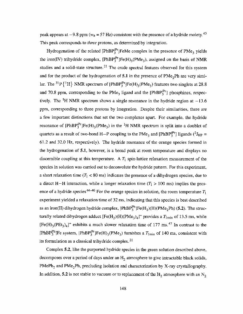
peak appears at -9.8 ppm (wh = 57 Hz) consistent with the presence of a hydride moiety.43
This peak corresponds to three protons, as determined by integration.
Hydrogenation of the related [PhBPir]FeMe complex in the presence of PMe3 yields
the iron(IV) trihydride complex, [PhBPir]Fe(H) 3(PMe3), assigned on the basis of NMR
studies and a solid-state structure. 21 The crude spectral features observed for this system
and for the product of the hydrogenation of 5.1 in the presence of PMe2Ph are very simi-
lar. The 31p { H} NMR spectrum of [PhBPi'r]Fe(H) 3(PMe3) features two singlets at 28.8
and 70.8 ppm, corresponding to the PMe3 ligand and the [PhBP'P] phosphines, respec-
tively. The 'H NMR spectrum shows a single resonance in the hydride region at -13.6
ppm, corresponding to three protons by integration. Despite their similarities, there are
a few important distinctions that set the two complexes apart. For example, the hydride
resonance of [PhBPir]Fe(H) 3(PMe 3) in the 'H NMR spectrum is split into a doublet of
quartets as a result of two-bond H-P coupling to the PMe3 and [PhBPir] ligands (2 JHP =
61.2 and 32.0 Hz, respectively). The hydride resonance of the orange species formed in
the hydrogenation of 5.1, however, is a broad peak at room temperature and displays no
discernible coupling at this temperature. A Ti spin-lattice relaxation measurement of the
species in solution was carried out to deconvolute the hydride pattern. For this experiment,
a short relaxation time (T1 < 80 ms) indicates the presence of a dihydrogen species, due to
a direct H-H interaction, while a longer relaxation time (T1 > 100 ms) implies the pres-
ence of a hydride species44- 46 For the orange species in solution, the room temperature T
experiment yielded a relaxation time of 32 ms, indicating that this species is best described
as an iron(II) dihydrogen hydride complex, [PhBPPh]Fe(H2)(H)(PMe 2 Ph) (5.2). The struc-
turally related dihydrogen adduct [Fe(H2)(H)(PMe 3)4 + provides a Tmin of 13.5 ms, while
[Fe(H) 3(PEt3)4]* exhibits a much slower relaxation time of 177 ms. 47 In contrast to the
[PhBP~h]Fe system, [PhBPir]Fe(H) 3(PMe 3) furnishes a Timin of 140 ms, consistent with
its formulation as a classical trihydride complex.21
Complex 5.2, like the purported hydride species in the green solution described above,
decomposes over a period of days under an H2 atmosphere to give intractable black solids,
PMePh2 and PMe2Ph, precluding isolation and characterization by X-ray crystallography.
In addition, 5.2 is not stable to vacuum or to replacement of the H2 atmosphere with an N2
148
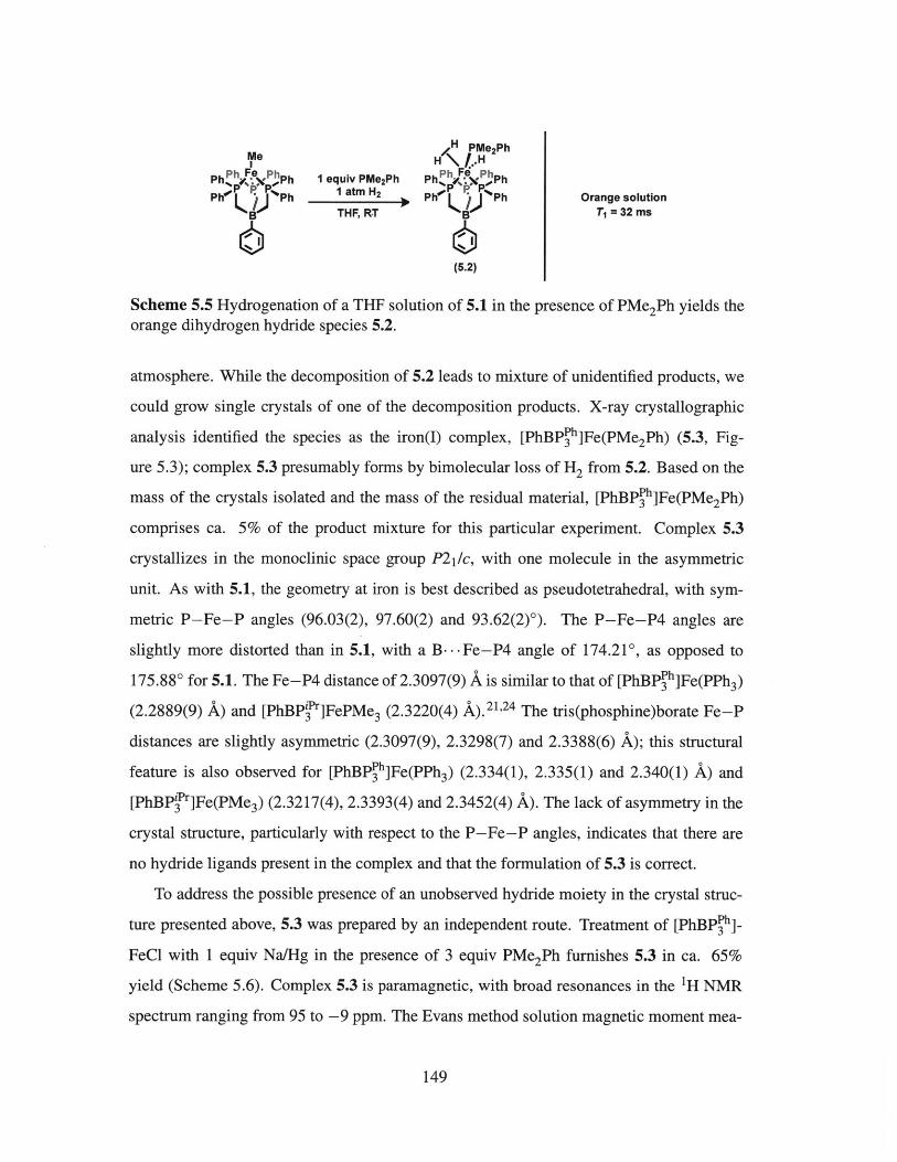
MH PMe2PhMe 2
Ph Fe Ph I equiv PM0 2Ph PhP F4 Ph
Ph' P.Ph - atm H2 y Pe Ph Orange solutionB THF, RT BT 1 =32ms
(5.2)
Scheme 5.5 Hydrogenation of a THF solution of 5.1 in the presence of PMe 2Ph yields theorange dihydrogen hydride species 5.2.
atmosphere. While the decomposition of 5.2 leads to mixture of unidentified products, we
could grow single crystals of one of the decomposition products. X-ray crystallographic
analysis identified the species as the iron(I) complex, [PhBPPh]Fe(PMe2 Ph) (5.3, Fig-
ure 5.3); complex 5.3 presumably forms by bimolecular loss of H2 from 5.2. Based on the
mass of the crystals isolated and the mass of the residual material, [PhBPPh]Fe(PMe 2Ph)
comprises ca. 5% of the product mixture for this particular experiment. Complex 5.3
crystallizes in the monoclinic space group P21/c, with one molecule in the asymmetric
unit. As with 5.1, the geometry at iron is best described as pseudotetrahedral, with sym-
metric P-Fe-P angles (96.03(2), 97.60(2) and 93.62(2)'). The P-Fe-P4 angles are
slightly more distorted than in 5.1, with a B ... Fe-P4 angle of 174.210, as opposed to
175.88' for 5.1. The Fe-P4 distance of 2.3097(9) A is similar to that of [PhBPPh]Fe(PPh3)
(2.2889(9) A) and [PhBPf]FePMe3 (2.3220(4) A).21,24 The tris(phosphine)borate Fe-P
distances are slightly asymmetric (2.3097(9), 2.3298(7) and 2.3388(6) A); this structural
feature is also observed for [PBP3h]Fe(PPh3) (2.334(1), 2.335(1) and 2.340(1) A) and
[PhBPf'r]Fe(PMe 3) (2.3217(4), 2.3393(4) and 2.3452(4) A). The lack of asymmetry in the
crystal structure, particularly with respect to the P-Fe-P angles, indicates that there are
no hydride ligands present in the complex and that the formulation of 5.3 is correct.
To address the possible presence of an unobserved hydride moiety in the crystal struc-
ture presented above, 5.3 was prepared by an independent route. Treatment of [PhBPPh]_
FeCl with 1 equiv Na/Hg in the presence of 3 equiv PMe2Ph furnishes 5.3 in ca. 65%
yield (Scheme 5.6). Complex 5.3 is paramagnetic, with broad resonances in the 1H NMR
spectrum ranging from 95 to -9 ppm. The Evans method solution magnetic moment mea-
149

Selected Bond Lenaths (A) and Angles (a)Fe-PI = 2.3298(7)Fe-P2 = 2.3388(6)Fe-P3 = 2.3066(7)Fe-P4 = 2.3097(9)
PI-Fe-P2 = 96.03(2)PI-Fe-P3 = 97.60(2)P2-Fe-P3 = 93.62(2)
B---Fe-P4 = 174.21
Figure 5.3 Solid-state structure of 5.3. Thermal ellipsoids are drawn at 40% probability.Hydrogen atoms are omitted for clarity.
ClI
Ph% #*Ph 1 equiv Na/HgPh P 3 equiv PMe 2Ph
Ph /) Ph - THFB
PMe 2Ph
Ph F Ph
Ph V-VPh
B
(5.3)
Yellow powderS = 32
65% yield
Scheme 5.6 Independent synthesis of 5.3 by reduction of [PhBP h]FeCl with Na/Hg in thepresence of excess PMe2Ph.
surement of 4.1 jiB in C6D6 is higher than the spin-only value of 3.87 AB for three unpaired
electrons. This S = 3/2 ground state is consistent with that of [PhBPPh]Fe(PPh 3). 24 Com-
parison of the 'H NMR spectrum of the crystals described above and of 5.3 indicates that
the two materials are identical. Complex 5.3 does not bind or react with 1 atm H2 at room
temperature or upon heating to 60 'C, implying that, once formed, 5.3 cannot re-enter
the catalytic cycle, supporting the lack of unobserved hydrides in the crystal structure de-
scribed above. Whereas no additional information about the olefin insertion and subsequent
alkane release processes beyond what had been previously reported21 was gleaned in this
study, the move to a less electron-donating tris(phosphine)borate ligand did allow for the
characterization of a dihydrogen hydride species. This type of complex was invoked in
the hydrogenation of olefins by [PhBP'13]FeMe, although no spectroscopic evidence for its
formation could be obtained.
150
P4e
P3 P2 P
B

5.4 Accessing the Iron Chemistry of Bis(phosphine)borate
Ligands
Having observed hydrogenation of 1-hexene, we sought to develop a more robust and ac-
tive iron system while maintaining a similar ligand set. We reasoned that removal of a
ligand arm from the [PhBP h] framework would serve two purposes: first, a less sterically
encumbering ligand could allow substrates better access to the metal center and second,
decomposition via B-Calkyl bond cleavage could be circumvented, or at least tempered,
by virtue of there being one fewer susceptible linkage. The Peters group has developed
the 2 nd and 3rd row metal chemistry of the bis(phosphine)borate ligand [Ph 2BPPh], primar-
ily within the context of C-H and E-H bond activation and copolymerization catalysis
(Figure 5.4).48-50 These zwitterionic complexes complement their cationic relatives in that
they (i) are soluble in non-coordinating and less polar solvents, (ii) have the potential for
increased functional group tolerance relative to the cationic systems and (iii) should not
exhibit the counterion effects that are sometimes observed in discrete salt systems.
Ph2 Ph 2 Ph 2 Ph 2
P 00r- s L + P/-P.. +, Me Ph--P + #NCCH 3 Ph2B ,P .Me
Ph 2 SiP L P THF P 0 NCCH 3 -P THFPh2 Ph 2 Ph 2 Ph 2
C-H Bond E-H Bond CO/C 2H4Activation Activation Copolymerization
Figure 5.4 Comparison of metal complexes containing neutral bis(phosphine)silane (left)and anionic bis(phosphine)borate ligands (right).
The bis(phosphine)borate scaffold also benefits from facile modification at both the
boron and phosphorus centers. Although Thomas was able to install a number of aryl
groups on the boron center, he found that variation of the borate substituent had little
effect on the overall electronic structure of resulting metal complex. 51 Modification of
the phosphine substituents had a more pronounced effect, consistent with a description
in which the borate unit is electronically insulated from the metal center. To develop
the iron chemistry of bis(phosphine)borate ligands within the context of the hydrogena-
tion chemistry presented in previous sections, two ligand frameworks were targeted. The
151
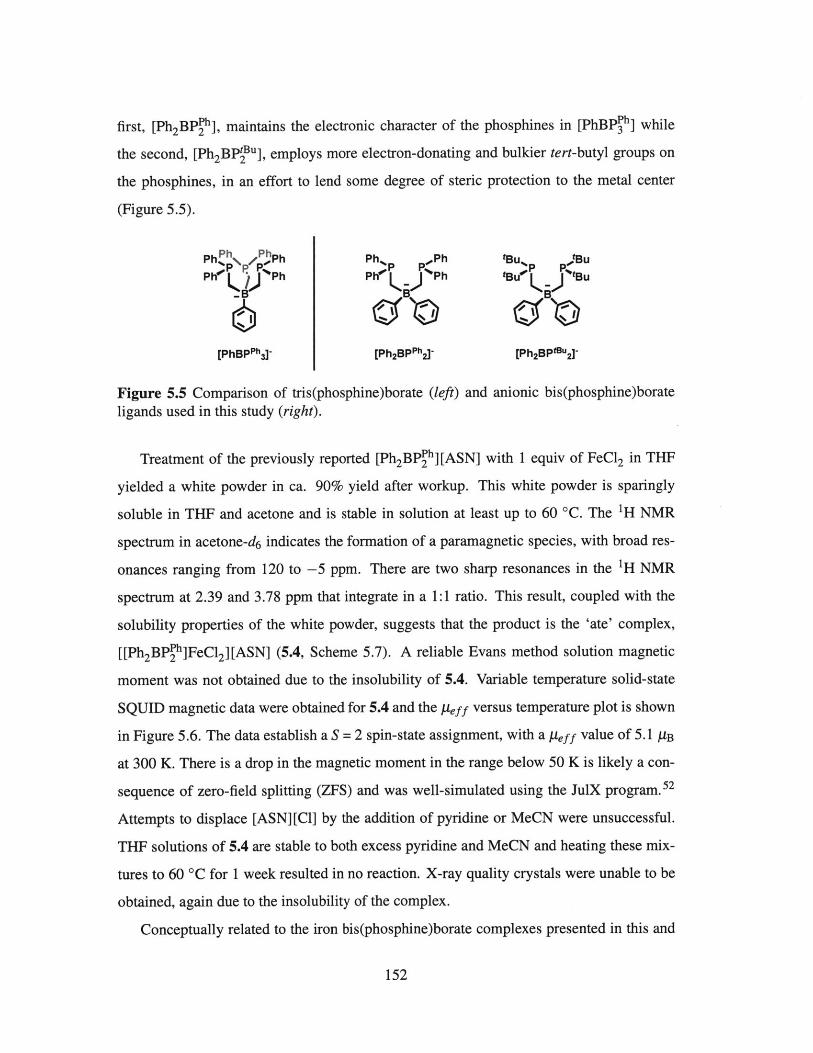
first, [Ph2BPPh], maintains the electronic character of the phosphines in [PhBP h] while
the second, [Ph 2BPIBu], employs more electron-donating and bulkier tert-butyl groups on
the phosphines, in an effort to lend some degree of steric protection to the metal center
(Figure 5.5).
Ph Ph ,PhPh Ph% ,Ph tBU* BUPh R?;Ph Ph _%Ph tBU tBu
[PhBPPh3] [Ph 2 BPPh2]- [Ph2BP"u 2 -
Figure 5.5 Comparison of tris(phosphine)borate (left) and anionic bis(phosphine)borateligands used in this study (right).
Treatment of the previously reported [Ph 2BPPh][ASN] with 1 equiv of FeCl2 in THF
yielded a white powder in ca. 90% yield after workup. This white powder is sparingly
soluble in THF and acetone and is stable in solution at least up to 60 'C. The 'H NMR
spectrum in acetone-d 6 indicates the formation of a paramagnetic species, with broad res-
onances ranging from 120 to -5 ppm. There are two sharp resonances in the 'H NMR
spectrum at 2.39 and 3.78 ppm that integrate in a 1:1 ratio. This result, coupled with the
solubility properties of the white powder, suggests that the product is the 'ate' complex,
[[Ph2BP~h]FeCl 2][ASN] (5.4, Scheme 5.7). A reliable Evans method solution magnetic
moment was not obtained due to the insolubility of 5.4. Variable temperature solid-state
SQUID magnetic data were obtained for 5.4 and the peff versus temperature plot is shown
in Figure 5.6. The data establish a S = 2 spin-state assignment, with a Ieff value of 5.1 AB
at 300 K. There is a drop in the magnetic moment in the range below 50 K is likely a con-
sequence of zero-field splitting (ZFS) and was well-simulated using the JulX program.52
Attempts to displace [ASN][Cl] by the addition of pyridine or MeCN were unsuccessful.
THF solutions of 5.4 are stable to both excess pyridine and MeCN and heating these mix-
tures to 60 *C for 1 week resulted in no reaction. X-ray quality crystals were unable to be
obtained, again due to the insolubility of the complex.
Conceptually related to the iron bis(phosphine)borate complexes presented in this and
152

Ph% Ph
PhK Ph N
Cl ClFe .,
Phi \ .Ph NDFeC12 1 P N'* PTHF B )
(5.4)
Scheme 5.7 Treatment of [Ph2BP h][ASN] with FeCl2 yields the 'ate' complex 5.4.
0 50 100 150 200 250 300K.. .. I.
pnppppppppppppppppp~
I .1... I .1,,,, I,, .1-
0 50 100 150T (K)
200 250
Figure 5.6 SQUID magnetometry datag = 2.113, D = 7.033.
(0.5 T) and fit for 5.4. JulX simulation parameters:
the following sections is the iron #-diketiminate chemistry reported by Holland. In explor-
ing the preparation of iron(II) halide complexes, Holland found that simple modification of
the #-diketiminate ligand had a significant effect on the identity of the resulting complex,
yielding either LMeFe(p-Cl) 2Li(THF)2 or LtBUFeCl, depending on the bulkiness of the
substituents on the /-diketiminate backbone (LMe = 2,4-bis(2,6-diisopropylphenylimido)-
pentyl; LtBU = 2,2,6,6-tetramethyl-3,5-bis(2,6-diisopropylphenylimido)-hept-4-yl). 5 3 In an
attempt to realize a similar effect and access a lower-coordinate species, we pursued the
iron chemistry of the bulkier alkyl substituted bis(phosphine)borate, [Ph 2BPBu]. Treat-
ment of [Ph2BPBu][Tl] with 1 equiv of FeBr2 resulted in the formation of a dark orange
153
White powder93% yield
7
6
5
M3
2
1
0
7
6
5
4
3
2
1
0300
I I I
4

solution and a white precipitate (Scheme 5.8). After workup, an amber powder was isolated
in ca. 60% yield. This species is paramagnetic, with 1H NMR resonances ranging from 65
to -115 ppm. X-ray crystallographic analysis by Lu54 identified the species as the dimeric
{ [Ph2 BPfu]FeBr1 2 complex (5.5, Figure 5.7). Complex 5.5 crystallizes in the triclinic
space group P!, with one molecule per asymmetric unit. The average Fe-P bond length
of 2.4529(2) A is typical of a pseudotetrahedral four-coordinate, iron(II) bis(phosphine)
dibromide complex. The Fe2(g-Br)2 core is fairly symmetric, as reflected by the Fe-Br
bond lengths of 2.5238(3) and 2.5395(3) A. These bond lengths are similar to th6se of other
structurally characterized, four-coordinate iron (A -Br) 2 complexes (2.45 - 2.57 A).55-58
The Fe-Fe distance is 3.5630 A precluding a direct metal-metal interaction. The iron and
phosphorus atoms are coplanar, with the two bromine atoms residing above and below the
plane, resulting in a distorted tetrahedral geometry at each iron center.
tBu ,Bl + fB tBu tBu fBUtBU K)IfBu r - Br P-"\ Amber powder
* 0.5 B Fe Fe B S=2THF \_p/ 60% yield
tBu tBu M~u f*Bu ;
(5.5)
Scheme 5.8 Treatment of [Ph2BP u][Tl] with FeBr2 yields the dimeric (yg-Br)2 complex5.5.
Selected Ian Lengths L& and Angles e*lFel-PI = 2.4438(3)Fel -P2 = 2.4577(3)
P4 Fe2-P3 = 2.4516(3)P B1Fe2-P4 = 2.4585(3)
B2 Be FFel-Bri = 2.5238(3)Fel -Br2 = 2.5395(3)
Brl P2 Fe2-Brl = 2.5238(3)P3 Fe2-Br2 - 2.5290(3)
Brl-Fel-Br2 = 90.31(3)Bri -Fe2-Br2 = 90.64(3)P1-Fel-P2 =100.81(3)P3-Fe2-P4 = 99.18(3)
Figure 5.7 Solid-state structure of 5.5. Thermal ellipsoids are drawn at 40% probability.Hydrogen atoms are omitted for clarity.
Notable is that although the use of [Ph2BPfu] did allow for the formation of a neutral
species by salt metathesis, substitution of FeBr2 with FeCl2 does not form the expected ana-
logue of 5.5. Instead, [[Ph 2BPBu]FeCl 2][Tl] was structurally characterized by Lu. 54 The
154

complex [[Ph2 BPPh]FeCl 2][Ti] crystallizes in the monoclinic space group P21/n, with one
molecule in the asymmetric unit (Figure 5.8). The iron center is in a pseudotetrahedral ge-
ometry, bound by the two phosphines of the bis(phosphine)borate and two chlorides. The
Fe-P bond lengths of 2.4462(2) and 2.3552(2) A are typical of other pseudotetrahedral
four-coordinate, iron(II) bis(phosphine) dichloride complexes (2.41 - 2.55 A). Notably,
removal of the chloride ligand to generate TlCl does not occur, despite the well-known
application of thallium(I) salts as potent halide abstraction reagents. Instead, the thallium
counterion is bound to a chlorine atom, resulting in a Fe-(p-Cl)-Tl interaction; this
M-X-Tl (M = transition metal, X = Cl, F) structural motif is relatively rare. The Ti-Cll
bond length of 2.9538(2) A and the TI ... C12 distance of 3.2140(2) A are in the range of
those observed for other M-X-Tl complexes (2.39 - 3.63 A).59 71 The Fe-Cl distances
(2.2860(2) and 2.2978(3) A) are similar to other structurally characterized, mononuclear,
4-coordinate iron dichloride complexes containing a Cl-Fe-(Y-Cl)-M (M = Li, K) frag-
ment. 53,72-77 Although an argument can be made for Fe-Cl-Ti being a preferred structural
motif over Fe-Br-Tl based on the lattice energies of Fe-X and Tl-X (X = Cl or Br), it
remains unclear as to why the two complexes adopt different overall configurations ('ate'
vs dimeric).
C12 C11
tBu B C C I+ Fe
0Bu ) u /Bu \ BuBu t#,t~u
T)tBFB T g Buol Bu P1 P2
B B
Figure 5.8 (left) Synthesis of [[Ph2BPPh]FeCl2][Ti]. (right) Solid-state structure of
[[Ph2BP h]FeCl 2][Ti]. Thermal ellipsoids are drawn at 40% probability. Hydrogen atomsare omitted for clarity.
155

5.5 Preparation of Bis(phosphine)borate Anilido and Ar-
yloxide Complexes
Attempts to reduce 5.4 with Na/Hg, NaCIOH8 or KC 8 in the presence or absence of PMe 3,
PPh3 or PMe2Ph resulted in the formation of a mixture of products, the majority of which
were intractable black solids and free MePh 2P via B-alkyl bond cleavage (vide infra).
Gratifyingly, anilido and aryloxide complexes of [Ph 2 BPPh]Fe could be obtained by salt
metathesis routes. Treatment of a THF slurry of 5.4 at -35 'C with LiNHAr (Ar = 2,6-
diisopropylphenyl) resulted in a color change from white to dark orange over the period
of 3 h. Analysis of the reaction mixture by 1H NMR spectroscopy indicated the quanti-
tative consumption of 5.4 and the formation of a new, paramagnetic species, as well as
free H 2NAr. Crystallographic structure determination of the major product by Lu5 4 es-
tablished its identity as the bis(anilido) complex, [[Ph 2 BP h]Fe(NHAr)2][ASN] (5.6, ca.
50%, Scheme 5.9). Complex 5.6 is paramagnetic, with 'H NMR signals ranging from 110
to -80 ppm. The Evans method solution magnetic moment measurement (peff = 5.4 AB,
CD 2 Cl 2 , 25 C) is consistent with an S = 2 ground state. Complex 5.6 crystallizes in the
monoclinic space group C2/c, with half a molecule in the asymmetric unit (Figure 5.9).
The Fe-P distance of 2.4903(2) A is similar to those of the related high-spin [PhBP h]Fe
complexes described in previous sections of this chapter. The Fe-N distance of 1.9749(2)
A falls within the range of other structurally characterized, four-coordinate iron complexes
containing a monodentate anilido ligand (1.88 - 2.03 A).2 2 ,7 8 83 The Fe-N-C angle of
the anilido ligand is bent, at 136.91(3)0; the hydrogen atoms bound to nitrogen were lo-
cated in the difference map and refined. A bent anilido ligand was also observed for the
related [PhBPPh]FeNH(p-tol) complex, which exhibits an Fe-N-C angle of 127.4(2)0.22
The addition of 0.5 equiv 12 to a THF solution of 5.6 at room temperature did not result in
the formation of [ASN] [I] and [Ph2 BPPh]Fe(NH(Ar)) 2 , but rather no reaction.
Aryloxide complexes can be accessed by the same method; treatment of a THF slurry
of 5.4 at -35 'C with one equiv of TIOAr (Ar = 2,6-diisopropylphenyl) afforded yellow
[[Ph2 BPPh]Fe(Cl)(OAr)][ASN] (5.7) in ca. 75% yield (Scheme 5.10, left). This species is
156

c - ArHN NHAr -F Fe
PhP\Ph +LINHAr P P C Orange powderFeo **P L bH Ph% / \ PhI S=2
L THF, -356 C B 53% yield
(5.6)
Scheme 5.9 Treatment of 5.4 with LiNHAr (Ar = 2,6-diisopropylphenyl) yields thebis(anilido) complex 5.6.
Selected Bond Lenaths (A) and Anales (*)Fe Fe-P = 2.4903(2)
Fe-N = 1.9749(2)PA PP-Fe-PA = 86.36 (3)
N-Fe-NA = 128.71(3)
Figure 5.9 Solid-state structure of 5.6. Thermal ellipsoids are drawn at 40% probability.ASN counterion and hydrogen atoms are omitted for clarity.
paramagnetic, with 1H NMR resonances ranging from 103 to -43 ppm; the Evans method
solution magnetic moment of 5.1 yB is slightly higher than the spin-only value of 4.90 yB
for four unpaired electrons, indicating an S = 2 ground state. The orange bis(aryloxide)
species, [[Ph2BPPh]Fe(OAr) 2][ASN] (5.8), was prepared in ca. 50% yield by treatment
of a THF slurry of 5.4 at -35 'C with two equiv of TlOAr (Ar = 2,6-diisopropylphenyl,
Scheme 5.10, right). As with 5.7, this species is paramagnetic with IH NMR signals rang-
ing from 97 to -41 ppm; the Evans method solution magnetic moment is 5.1 JB, consistent
with an S = 2 ground state. Single crystals of 5.8 were not obtained, however its structure
is likely similar to that of 5.6.
Complex 5.7 crystallizes in the triclinic space group PI with one molecule per asym-
metric unit. The iron center is again in a pseudotetrahedral geometry, ligated by the
two phosphines of the bis(phosphine)borate ligand, one aryloxide and one chloride (Fig-
ure 5.10). Overall, the structural parameters of 5.7 are very similar to those of 5.6, with an
157
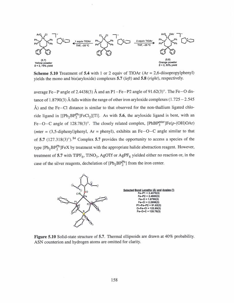
AFe CI -C, C - ArO OAr -
Pe PeP % P.,PPh% / \ Ph 1 equiv TIOAr Ph, h Fe 2 equiv TIOAr P pN'PPh Ph THF, -35 C Ph Ph THF, -35 GC B
(5.7) (5.8)Yellow powder Orange powder
S =2,75% yield S= 2, 53% yield
Scheme 5.10 Treatment of 5.4 with 1 or 2 equiv of TlOAr (Ar = 2,6-diisopropylphenyl)yields the mono and bis(aryloxide) complexes 5.7 (left) and 5.8 (right), respectively.
average Fe-P angle of 2.4438(3) A and an P1 -Fe-P2 angle of 91.62(3)0. The Fe-O dis-
tance of 1.8790(3) A falls within the range of other iron aryloxide complexes (1.725 - 2.545
A) and the Fe-Cl distance is similar to that observed for the non-thallium ligated chlo-
ride ligand in [[Ph 2BPph]FeCl 2][T]. As with 5.6, the aryloxide ligand is bent, with an
Fe-O-C angle of 128.78(3)0. The closely related complex, [PhBPyter]Fe(p-(OH)OAr)
(mter = (3,5-diphenyl)phenyl, Ar = phenyl), exhibits an Fe-O-C angle similar to that
of 5.7 (127.318(3)0 ).84 Complex 5.7 provides the opportunity to access a species of the
type [Ph 2BP h]FeX by treatment with the appropriate halide abstraction reagent. However,
treatment of 5.7 with TIPF6, TlNO 3, AgOTf or AgPF 6 yielded either no reaction or, in the
case of the silver reagents, dechelation of [Ph2BPPh] from the iron center.
Selected VD Lenaths i nD AngLesElCl OFe-P1 = 2.4375(3)
Fe Fe-P2 = 2.4500(3)Fe-O = 1.8790(3)
P 2Fe-Cl = 2.2698(3)PI-Fe-P2 = 91.62(3)O-Fe-Cl = 122.89(3)
B Fe-O-C = 128.78(3)
Figure 5.10 Solid-state structure of 5.7. Thermal ellipsoids are drawn at 40% probability.ASN counterion and hydrogen atoms are omitted for clarity.
158
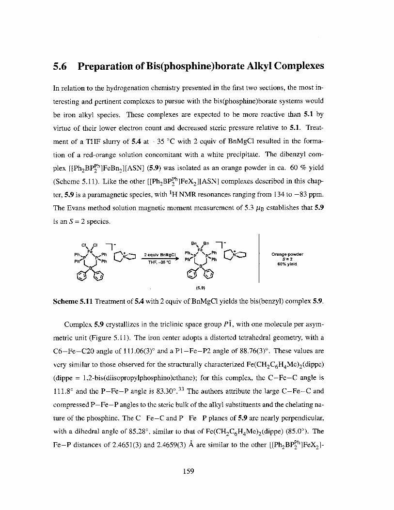
5.6 Preparation of Bis(phosphine)borate Alkyl Complexes
In relation to the hydrogenation chemistry presented in the first two sections, the most in-
teresting and pertinent complexes to pursue with the bis(phosphine)borate systems would
be iron alkyl species. These complexes are expected to be more reactive than 5.1 by
virtue of their lower electron count and decreased steric pressure relative to 5.1. Treat-
ment of a THF slurry of 5.4 at -35 'C with 2 equiv of BnMgC1 resulted in the forma-
tion of a red-orange solution concomitant with a white precipitate. The dibenzyl com-
plex [[Ph2BP~h]FeBn 2][ASN] (5.9) was isolated as an orange powder in ca. 60 % yield
(Scheme 5.11). Like the other [[Ph2BPPh]FeX 2] [ASN] complexes described in this chap-
ter, 5.9 is a paramagnetic species, with 1H NMR resonances ranging from 134 to -83 ppm.
The Evans method solution magnetic moment measurement of 5.3 MB establishes that 5.9
is an S = 2 species.
Cl N i / - Bn Bn/ -
Ph% Ph [-+ 2 equiv BnMgCI Ph, . \ 'P Orange powder
Ph Ph THF, -35 C B Ph S=2B- P 60% yield
(5.9)
Scheme 5.11 Treatment of 5.4 with 2 equiv of BnMgCl yields the bis(benzyl) complex 5.9.
Complex 5.9 crystallizes in the triclinic space group P!, with one molecule per asym-
metric unit (Figure 5.11). The iron center adopts a distorted tetrahedral geometry, with a
C6-Fe-C20 angle of 111.06(3)' and a P1-Fe-P2 angle of 88.76(3)'. These values are
very similar to those observed for the structurally characterized Fe(CH 2C6H4Me) 2(dippe)
(dippe = 1,2-bis(diisopropylphosphino)ethane); for this complex, the C-Fe-C angle is
111.8' and the P-Fe-P angle is 83.30' 33 The authors attribute the large C-Fe-C and
compressed P-Fe-P angles to the steric bulk of the alkyl substituents and the chelating na-
ture of the phosphine. The C-Fe-C and P-Fe-P planes of 5.9 are nearly perpendicular,
with a dihedral angle of 85.28', similar to that of Fe(CH 2C6H4Me)2 (dippe) (85.00). The
Fe-P distances of 2.4651(3) and 2.4659(3) A are similar to the other [[Ph 2BP h]FeX 2 1-
159

[ASN] described in this chapter. The Fe-C distances of 2.1079(3) and 2.1833(3) A are not
significantly different from the average 2.103 A reported for iron alkyl complexes contain-
ing sp 3-alkyl ligands.
C20C6 Selected IkUW Lengths & Aand Angles *l
Fe Fe-P1 = 2.4651(3)Fe-P2 = 2.4659(3)
P1 Fe-C6 = 2.1833(3)P2, Fe-C20 = 2.1079(3)
C6-Fe-C20 = 111.06(3)PI-Fe-P2 = 88.76(3)
B
Figure 5.11 Solid-state structure of 5.9. Thermal ellipsoids are drawn at 40% probability.ASN counterion and hydrogen atoms are omitted for clarity.
Encouraged by this result, we turned to the [Ph 2BPu] ligand scaffold to isolate a
three-coordinate iron alkyl complex. Treatment of 5.5 with two equiv of BnMgCl in OEt2at -35 'C resulted in an immediate color change from yellow to red and the formation of
a white precipitate. After stirring for 30 min, a red powder was isolated in ca. 60% yield
(Scheme 5.12). This species, assigned as the three-coordinate [Ph2BPfu]FeBn complex
(5.10), is a paramagnetic, S = 2 species (peg = 5.0 AB, C6D6 , 25 'C), with 1H NMR res-
onances ranging from 65 to -115 ppm. An X-ray crystallographic study confirmed the
assignment of 5.10 as the three-coordinate iron alkyl species. Complex 5.10 crystallizes in
the monoclinic space group P21/n, with one molecule per asymmetric unit (Figure 5.12).
The sum of the angles about the iron center is 359.86(3)0, indicating a planar geometry. As
a consequence of the lower coordination number in 5.10, the P-Fe-P angle expands to
101.54(3)0, as compared to 83.30(3)0 for four-coordinate 5.9. The P-Fe-C angles are in-
equivalent; the Pl-Fe-C12 angle is 132.73(3)0 and the P2-Fe-C12 angle is 125.59(3)0.
This asymmetry can be attributed to the steric demands of the benzyl ligand and has been
observed for other three- and four-coordinate iron alkyl complexes bearing bulky alkyl
substituents.21,27,31,33,38,39,85-90 For example, the three-coordinate alkyl complex reported
160
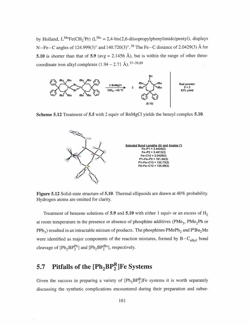
by Holland, LMeFe(CH 2iPr) (LMe = 2,4-bis(2,6-diisopropylphenylimido)pentyl), displays
N-Fe-C angles of 124.999(3)0 and 140.720(3)0.39 The Fe-C distance of 2.0429(3) A for
5.10 is shorter than that of 5.9 (avg = 2.1456 A), but is within the range of other three-
coordinate iron alkyl complexes (1.94 - 2.71 A).37 39 ,89
fBu Bu tBu tBu
B pFe Fep
tBu tBu f* Bu
2 BnMgCIOEt, -35 'C
Bn
FetBuF N.fflu2 ffui K ,. Bu
(.B)
1(5.10)
Scheme 5.12 Treatment of 5.5 with 2 equiv of BnMgCl yields the benzyl complex 5.10.
C12
Fe
P2P
B
Selected DpW Lenaths LA And Angles *)Fe-P1 = 2.4424(3)Fe-P2 = 2.4513(3)
Fe-C12 = 2.0429(3)P1-Fe-P2 = 101.54(3)PI-Fe-C12 = 132.73(3)P2-Fe-C12 = 125.59(3)
Figure 5.12 Solid-state structure of 5.10. Thermal ellipsoids are drawn at 40% probability.Hydrogen atoms are omitted for clarity.
Treatment of benzene solutions of 5.9 and 5.10 with either 1 equiv or an excess of H2
at room temperature in the presence or absence of phosphine additives (PMe3, PMe2Ph or
PPh3) resulted in an intractable mixture of products. The phosphines PMePh 2 and PtBu 2Me
were identified as major components of the reaction mixtures, formed by B-Caiky bond
cleavage of [Ph2 BPPh] and [Ph2BPBu], respectively.
5.7 Pitfalls of the [Ph2BP"]Fe Systems
Given the success in preparing a variety of [Ph2BPR]Fe systems it is worth separately
discussing the synthetic complications encountered during their preparation and subse-
161
Red powderS2
63% yield

quent chemistry. Although a promising starting point for the preparation of low-coordinate
species, isolation of complexes of the type [Ph 2BPBu]FeX has proven to be difficult as a re-
sult of the solubility of the desired products and their side-products in a range of solvents,
including O(SiMe3)2 and SiMe 4. In addition to the solubility problem, a persistent and
ill-defined decomposition pathway exists for these species, preventing isolation. For exam-
ple, treatment of 5.5 with one equiv of LiNHAr (Ar = 2,6-diisopropylphenyl) results in a
color change from amber to bright orange with concomitant formation of a white precipi-
tate. A 'H NMR spectrum of the crude reaction mixture indicates the formation of a new
paramagnetic species, assumed to be the three-coordinate [Ph 2BPu]FeNHAr by compar-
ison to the 1H NMR spectrum of 5.10. Also prominent in the spectrum is the presence
of free NH2 Ar; upon standing in solution, the purported three-coordinate anilido species
decays over a period of hours and the concentrations of free NH2 Ar and other unidentified
products increase. In the crude 31P NMR spectrum, both free [Ph 2BPfu] and PMetBu2
are present; accordingly, a dark solid presumed to be Fe0 can be seen precipitating from
solution. These observations are also true of the reaction between 5.5 and TlOAr (Ar =
2,6-diisopropylphenyl).
Reasoning that a sterically protected nitrogen center would give rise to a more stable
three-coordinate amide complex, 5.5 was treated with two equiv of LiN(p-tol) 2 in THF.
Immediately upon addition, a dark purple solution formed with a white precipitate. A crude
1H NMR spectrum indicated the clean formation of a new paramagnetic species. However,
a partial X-ray crystallographic analysis suggests that the species is the dimeric iron imido
complex, as shown in Figure 5.13 (left). Repeating the reaction in a non-coordinating
solvent such as C6 H6 gives the same product.
As discussed in the previous sections, further chemistry with the isolated [Ph 2 BPR]Fe
complexes is hampered by B-Calkyl bond cleavage to give free PMeR2 as a major prod-
uct in inconsistent quantities. For 5.4 in particular, treatment with various reductants (vide
supra) results in the formation of PMePh2 and FeO. A partial X-ray crystallographic analy-
sis indicates that [Ph2 BPPh] 2 Fe is also produced (Figure 5.13, right).
162

2- Ph, Ph~ Ph Ptol ol tol I 2- B F P- B
toI~..N % Fe .-l 2 U F
% tol tol tof Ph Ph Ph Phtol tol
Figure 5.13 Preliminary X-ray analyses suggest that: (left) Treatment of 5.5 with LiN(p-tol) 2 results in dechelation of [Ph2 BPBu] and formation of an homoleptic iron amido
species. (right) Reduction of 5.4 results in a mixture of products, one of which is the
homoleptic bis(phosphine)borate complex.
5.8 Conclusions and Future Work
In this chapter, the preparation and characterization of an iron alkyl complex supported
by the tris(phosphine)borate ligand [PhBPh] was described. In contrast to the related
[PhBP'pr]FeMe complex, hydrogenation of [PhBPPh]FeMe in the presence of PMe2 Ph
yields a transient dihydrogen hydride species, as evidenced by a short T relaxation time
of 32 ms. Complex [PhBPPh]FeMe is a very slow but competent hydrogenation catalyst,
achieving a TOF of 3.3 h-1 for the conversion of 1-hexene to hexane. In an effort to access
more robust and active catalysts, the coordination chemistry of iron bis(phosphine)borate
complexes was explored. The less sterically hindered ligand, [Ph 2BPh]2 , allowed for
access of bis(alkyl), bis(anilido) and bis(aryloxide) 'ate' complexes; the bulkier ligand,
[Ph2 BP'2Bu], supported the formation of an unusual three-coordinate iron alkyl complex.
Both ligand sets suffered from similar B-Calkyl bond cleavage decomposition pathways
and both ligands could be easily displaced from iron under reducing conditions or by the
introduction of a strongly coordinating ligand. While the identity of the intermediate hy-
dride species in the tris(phosphine)borate system remains an interesting question, the lack
of experimental methods for the characterization of paramagnetic hydride and dihydrogen
complexes constitutes a major hurdle.
As mentioned before, ENDOR spectroscopy has been a useful tool in identifying the
presence of Fe-H bonds in nitrogenase intermediates. 7 Recently, this technique has been
used by the Schrock and Peters groups to characterize paramagnetic molybdenum hy-
dride and iron dihydrogen complexes, respectively. 9 1,92 Treatment of [HIPTN3 N]Mo(N 2 )
163

([HIPTN 3N] = ((HIPT)NCH 2CH 2)3N3-, HIPT = 3,5-(2,4,6-1Pr3C6H2) 2C6H3) with H2 gen-
erates an unstable "[HIPTN 3 N]Mo(H 2 )" species that undergoes facile heterolytic cleav-
age to yield [[HIPTN 3 N]Mo(H)]- and H' at low temperature, as identified by an EPR
and 1/ 2H/ 14 N ENDOR studies.91 The stable dihydrogen adduct [SiPir]Fe(H2 ) (LSiP'r] _
(2 -Pr 2 PC6 H4 )3Si ), generated by addition of H2 to [SiPir]Fe(N2 ), is a rare example of
a well-characterized, open-shell metal complex that binds H 2 . EPR and ENDOR data, as
well as an X-ray structure analysis, support the assignment of this species as an iron(l)
dihydrogen complex and not an iron(I) monohydride or an iron(III) dihydride species. 92
Thus, both EPR and ENDOR spectroscopic studies could provide further characterization
of the intermediate hydride species generated upon addition of H2 to [PhBPh]FeMe.
5.9 Experimental Methods
5.9.1 General Considerations
All manipulations were carried out using standard Schlenk or glovebox techniques under
a dinitrogen atmosphere. Unless otherwise noted, solvents were dried and deoxygenated
by sparging with argon and passing through activated alumina in a solvent purification
system from SG Waters USA, LLC (Nashua, NH). Non-halogenated solvents were tested
with a standard purple solution of sodium benzophenone ketyl in tetrahydrofuran in or-
der to confirm effective oxygen and moisture removal. Ethanol was stirred and distilled
over calcium sulfate and stored over activated 3-A molecular sieves. [PhBPh]FeCl, 2 4
[Ph 2BPPh][ASN], 9 3 [Ph2 BP2Bu][Tl], 5" and TlOAr 94 (Ar = 2,6-diisopropylphenyl) were
prepared according to literature methods. LiNHAr (Ar = 2,6-diisopropylphenyl) was pre-
pared from 2,6-diisopropylaniline and n-butyllithium in n-pentane. 2,6-Diisopropylaniline
was purchased from Aldrich and distilled prior to use. All other reagents were purchased
from commercial suppliers and used without further purification. Elemental analyses were
performed by Midwest Microlab, LLC (Indianapolis, IN) and Robertson Microlit Labora-
tories, Inc (Ledgewood, NJ). Deuterated solvents were purchased from Cambridge Isotope
Laboratories, Inc., degassed, and dried over activated 3-A molecular sieves prior to use.
164
5.9.2 Spectroscopic Measurements
Varian 300 and 500 MHz spectrometers were used to record 'H, 3 1P and 20 5T1 NMR spectra
at room temperature, unless otherwise noted. 'H NMR chemical shifts were referenced to
the residual solvent peaks. 3 1P NMR chemical shifts were referenced to external 85%
phosphoric acid (3 = 0 ppm). 20 5TI NMR chemical shifts were referenced to external
Tl(N0 3 ) (3 = 0 ppm). Solution magnetic moment measurements were determined by the
method of Evans. 9 5,9 6 To determine the error in these measurements, an error analysis was
performed and the error bars were established at 95% confidence using regression analysis.
The values are reported to two significant figures and are understood to have an error of
± 0.1 pB. Ti values were determined by fitting the pulse-recovery 1H spectra at room
temperature using the T calculation protocols in Varian's VnmrJ software.
5.9.3 Electrochemistry
Electrochemical measurements were carried out in a glovebox under a dinitrogen atmo-
sphere in a one-compartment cell using a CH Instruments 630-C Electrochemistry Ana-
lyzer with CHI Version 8.09 software package. A glassy carbon electrode and platinum
wire were used as the working and auxiliary electrodes, respectively. The reference elec-
trode was Ag/AgNO 3 in THF. Solutions of electrolyte (0.4 M ["Bu 4 N][PF6 ]) and analyte
were prepared in a glovebox. Experiments were conducted at room temperature. The fer-
rocene couple Fc/Fc* was used as an external reference.
5.9.4 Magnetic Measurements
Magnetic susceptibility measurements of powdered samples were performed on a Quantum
Design SQUID magnetometer at 0.5 T between 4 and 300 K for all samples. The samples
were measured in gelatin capsules, and the diamagnetic contribution from the sample con-
tainer was subtracted from the experimental data. Pascal's constants were used to subtract
diamagnetic contributions, yielding paramagnetic susceptibilities. JulX was used for the
simulation and analysis of magnetic susceptibility data. 52
165

5.9.5 Preparation of [PhBP h]FeMe (5.1)
A C6 H6 slurry of Me 2 Mg (199.2 mg, 3.69 mmol) was added to a solution of [PhBP h]FeCl
(286.7 mg, 0.37 mmol) in 10 mL of C6 H6 . After 2 h, the reaction mixture was filtered
through Celite and the filtrate lyophilized. The resulting powder was extracted into toluene,
filtered through Celite and the volatiles removed in vacuo to yield an amber solid (241.4
mg, 86%). X-ray quality crystals were grown by vapor diffusion of pentane into a concen-
trated C6H6 solution. 'H NMR (300 MHz, C6D6 ) 3 47.43, 22.60, 20.76, 2.77, -12.79,
-53.25, -53.25, -105.89. Peff (C6D6 , Evans method, 25 C): 5.2 PB. Anal. Calcd. for
C46H44BFeP3 : C, 73.04; H, 5.86; N, 0. Found: C, 72.72; H, 5.89; N, 0.
5.9.6 In Situ Generation of [PhBP h]Fe(PMe 2Ph)(H)(H 2) (5.2)
A J. Young capped NMR tube was charged with 5.1 (44.3 mg, 58.56 gmol), PMe2Ph (8.4
pL, 58.80 pmol) and 0.5 mL THF-d8 . The tube sealed and inverted to ensure complete
mixing. The solution was degassed by three freeze/pump/thaw cycles, and the NMR tube
was pressurized with 1 atm of H2 . 5.1 was consumed after 10 min, as determined by 1H
NMR spectroscopy. 'H NMR (500 MHz, THF-d8) 3 7.75 - 7.63 (m, 4H), 7.53 - 7.35 (m,
14H), 7.21 - 7.13 (m, 3H), 7.03 - 6.86 (m, 18H), 1.53 (s, 6H), 0.83 (s, 6H), -9.95 (br s,
3H). 31p { 1H} NMR (202 MHz, THF-d8) 8 61.6 (s, 3P), 32.9 (s, IP).
5.9.7 Preparation of [PhBP h]Fe(PMe2 Ph) (5.3)
Sodium (3.0 mg, 0.13 mmol) and mercury (489.2 mg) were stirred vigorously with THF
(5 mL). A solution of [PhBPh]FeCl (82.5 mg, 0.11 mmol) and PMe2 Ph (45.4 pL, 0.319
mmol) in THF (5 mL) was added and the reaction mixture stirred for 12 h at room temper-
ature. The resulting dark brown mixture was decanted from the amalgam and the solvent
removed in vacuo. The residue was extracted into C6 H6 and filtered through Celite and
lyophilized. The resulting brown powder was taken up in minimal benzene and pentane
added to precipitate a dark yellow microcrystalline solid (60.6 mg, 65%). X-ray quality
crystals were grown by vapor diffusion of pentane into a concentrated C6 H6 solution. 1H
NMR (400 MHz, C6D6) 3 94.59 (br), 92.61 (br), 15.45, 13.77, 11.82, 8.71, 7.63, -1.23,
166

-5.60, -8.70. yeff (C6D6 , Evans method, 25 'C): 4.1 MB. Anal. Calcd for C53H52BFeP 4:
C, 72.38; H, 5.96. Found: C, 72.15; H, 5.88.
5.9.8 Preparation of [[Ph2BP h]FeCl2][ASN] (5.4)
To a slurry of [Ph 2 BPPh][ASN] (1.8707 g, 2.71 mmol) in THF (10 mL) was added a slurry
of FeCl2 (0.3514 g, 2.77 mmol) in THF (10 mL) and the reaction stirred 12 h at room
temperature. The reaction mixture was filtered to collect the white precipitate and the
solids were thoroughly washed with THF (3 x 5 mL) and CH 2Cl2 (3 x 5 mL) Yield: 2.0555
g, 93%. 'H NMR (300 MHz, d6-acetone) 6 120.0, 15.16, 12.59, 8.19, 7.47, 3.78, 2.39,
-4.16. Peff (SQUID): 5.1 MB. Anal. Cald. for C46H50BCl2FeNP2 : C, 67.67; H, 6.17; N,
1.72. Found: C, 67.46; H, 6.37; N, 1.73.
5.9.9 Preparation of {[Ph2 BPtBu]FeBr} 2 (5.5)
A THF slurry of FeBr 2 (84.2 mg, 0.39 mmol) was added to a THF solution (10 mL) of
[Ph2 BPBu][Tl] (258.2 mg, 0.38 mmol) and stirred for 12 h at room temperature. The
reaction mixture was filtered through Celite and the solvent removed in vacuo. The residue
was extracted into hot C66, filtered through Celite and lyophilized to yield a dark yellow
powder (174.9 mg, 75%). 'H NMR (400 MHz, C6D6) 6 24.94, 14.26, 12.82, 8.65 (br),
1.56, 1.03, -5.59. Anal. Cald. for C60 HIOOB 2Br 2Fe2P4 : C, 58.19; H, 8.14. Elemental
analysis results were consistently low in carbon and hydrogen. Found: C, 52.01; H, 7.23.
Drying of the samples under vacuum at 60 'C and repeated measurements of independently
prepared material gave similar results. Because we have crystal structure information on
5.5 and a clean 'H NMR spectrum, we are confident of its identity and the deviations
between the calculated and experimental values may arise from NMR silent salts that were
unable to be washed away or from oxidation of the material, as 5.5 is quite air-sensitive.
5.9.10 Preparation of [[Ph 2 BPPh]Fe(NH(Ar)) 2][ASN] (5.6)
A solution of LiNHAr (Ar = 2,6-diisopropylphenyl) (46.5 mg, 0.25 mmol) in THF (5 mL)
cooled to -35 'C was added dropwise to a slurry of 5.4 (103.0 mg, 0.13 mmol) in THF
167

(10 mL) cooled to -35 'C. The reaction mixture gradually turned dark orange and was
stirred for 3 h at room temperature. The solvent was removed in vacuo and the residue was
triturated with C6 H6 . The resulting orange solids were dissolved in a minimal amount of
CH2 Cl 2 and filtered through Celite. Diffusion of OEt2 into a concentrated CH2 Cl2 solution
at -35 'C yielded orange crystals, which were separated from the mother liquor, washed
with cold OEt2 and dried (0.0728 g, 53%). 'H NMR (500 MHz, CD 2Cl 2) 3 109.73, 47.66,
15.64, 13.46, 7.21, 6.78, 6.48, 2.72, 1.91, -4.64, -79.70. 'eff (CD 2Cl2, Evans method,
25 C): 5.4 pB. Anal. Calcd for C70H86BFeN3P2 : C, 76.57; H, 7.89; N, 3.83. Found: C,
76.31; H, 7.97; N, 3.88.
5.9.11 Preparation of [[Ph2 BPPh]Fe(C1)(OAr)][ASN] (5.7)
A slurry of TlOAr (Ar = 2,6-diisopropylphenyl) (46.8 mg, 0.12 mmol) in THF (5 mL)
cooled to -35 'C was added dropwise to a slurry of 5.4 (100.0 mg, 0.12 mmol) in THF (10
mL) at -35 'C. The resulting bright yellow slurry was stirred for 6 h at room temperature.
The reaction mixture was filtered through Celite and the solvent removed in vacuo. The
residue was triturated with C66, dissolved in a minimal amount of THF and filtered.
Diffusion of OEt2 into a concentrated THF solution -35 'C yielded bright yellow crystals,
which were separated from the mother liquor, washed with cold OEt2 and dried (0.088 g,
75%). Crystals grown in this manner were suitable for X-ray diffraction studies. 'H NMR
(300 MHz, THF-d8) 3 102.07, 55.83, 22.11, 14.40, 13.83, 10.62, 8.98, 8.12, 6.75, 3.98,
1.92, 0.88, -4.30, -6.14, -42.13. peff (THF-d 8, Evans method, 25 C): 5.1 AB. Anal.
Calcd for C58H67BClFeNOP2 : C, 72.70; H, 7.05; N, 1.46. Found: C, 72.50; H, 7.23; N,
1.45.
5.9.12 Preparation of [[Ph 2 BP h]Fe(OAr) 2][ASN] (5.8)
A slurry of TlOAr (Ar = 2,6-diisopropylphenyl) (97.3 mg, 0.25 mmol) in THF (5 mL)
cooled to -35 'C was added dropwise to a slurry of 5.4 (103.6 mg, 0.13 mmol) in THF (10
mL) at -35 'C. The resulting orange slurry was stirred for 6 h at room temperature. The
reaction mixture was filtered through Celite and the solvent removed in vacuo. The residue
168

was triturated with OEt2 , dissolved in a minimal amount of CH 2Cl 2 and filtered. Diffusion
of pentane into a concentrated CH 2C12 solution at -35 'C yielded orange crystals, which
were separated from the mother liquor, washed with cold pentane and dried (73.4 g, 53%).
Crystals grown in this manner were suitable for X-ray diffraction studies. 'H NMR (300
MHz, CD 2 Cl2 ) 3 96.50, 48.60, 15.25, 7.45, 7.36, 7.03, 6.70, 5.15, 2.85, 1.99, 1.30, 1.16,
0.88, -4.83, -40.96. Peff (CD 2 Cl2, Evans method, 25 C): 5.1 jpB. Anal. Calcd for
C70 H84 BFeNO 2P 2 : C, 76.43; H, 7.70; N, 1.27. Found: C, 76.23; H, 7.62; N, 1.31.
5.9.13 Preparation of [[Ph2 BP h]Fe(Bn) 2][ASNI (5.9)
To a 1,4-dioxane:OEt 2 (1:1, 10 mL) slurry of 5.4 (102.6 mg, 0.13 mmol) cooled to -35
C was slowly added BnMgCl (125.7 pL, 2M in THF, 0.25 mmol). The reaction mixture
gradually turned orange and was stirred for 1 h at room temperature. The mixture was
filtered and the solvent was removed in vacuo. The resulting orange solids were dissolved
in a minimal amount of THF and filtered through Celite. Diffusion of OEt 2 into a concen-
trated THF solution at -35 'C yielded red crystals, which were separated from the mother
liquor, washed with cold OEt 2 and dried (0.0699 g, 60%). X-ray quality crystals were
grown by diffusion of OEt 2 into a concentrated CH 2C12 solution. 'H NMR (500 MHz,
CD 2Cl2) 3 133.36, 35.92, 15.49, 11.64, 8.30, 7.40, 2.63, -5.45, -82.71. Anal. Calcd for
C60H64BFeNP 2 * C4H8O2 : C, 75.67; H, 7.14; N, 1.38. Found: C, 75.29; H, 6.71; N, 1.54.
5.9.14 Preparation of [Ph2 BPtBu]FeBn (5.10)
To a solution of 5.5 (56.7 mg, 0.46 mmol) in OEt 2 (10 mL) cooled to -35 'C was slowly
added BnMgCl (45.8 pL, 2M in THF, 0.92 mmol). A white precipitate formed immediately
and the solution color changed from yellow to red. The reaction mixture was stirred for 30
min at room temperature and then filtered through Celite. Concentrating the solution and
cooling to -35 'C yielded red microcrystalline material; the crystals were separated from
the mother liquor, washed with cold OEt2 and dried (36.3 mg, 63%). Crystals grown in this
manner were suitable for X-ray diffraction studies. 1H NMR (500 MHz, C6D 6 ) 3 63.35,
49.91, 26.68, 22.62, 1.10, -5.35, -45.62, -48.35, -114.58. peff (C6D6, Evans method,
169
25 'C): 5.0 uB. Anal. Calcd for C37H57BFeP2 : C, 70.49; H, 9.11. Found: C, 69.95; H,
8.76.
5.9.15 X-ray Crystallographic Details
Single crystals of 5.1 and 5.3 were obtained by vapor diffusion of pentane into a C6 H6 so-
lution, crystals of 5.7 were grown by vapor diffusion of OEt 2 into a concentrated THF solu-
tion at -35 'C, crystals of 5.9 were obtained by vapor diffusion of OEt2 into a concentrated
CH 2 Cl 2 solution at -35 'C, crystals of 5.10 were grown by cooling a concentrated OEt2
solution to -35 'C. Low-temperature single crystal X-ray diffraction studies were carried
out at the MIT Crystallography Facility on a Bruker Kappa Apex II diffractometer with
Mo Ka radiation (X = 0.71073 A). Crystals were coated with Paratone-N oil and mounted
on in fiber loops. Structures were solved by direct or Patterson methods using SHELXS 9 7
and refined against F2 on all data by full-matrix least squares with SHELXL-97 9 8 using
established refinement techniques. 99 All non-hydrogen atoms were refined anisotropically.
All hydrogen atoms were included into the model at geometrically calculated positions
and refined using a riding model. The isotropic displacement parameters of all calculated
hydrogen atoms were fixed to 1.2 times the U values of the atoms they are linked to (1.5
times for methyl groups). Thermal ellipsoid diagrams were created using Olex2. 100 The
structures of 5.3 and 5.7 contained voids with disordered solvent molecules. The program
SQUEEZE 10 1 as implemented in Platon 10 2 was used to remove the contribution of the dis-
ordered solvent to the structure factors. The crystallographic details for 5.1, 5.3, 5.7 and
5.9 - 5.10 are summarized in Tables 5.2 and 5.3.
170

5.1 5.3Formula
Formula Weight
Temperature/K
Crystal syst.
Space group
Color
a/A
b/A
c/A
a/0
#/0y/0V/P
p (calc.)/(gcm-1)
zNo. refl.
No. unique refl.
Rin,
RI (all data)b
wR2 (all data)b
R 1 [(I >2u)]
wR2 [(I >2a)]
GOFc
C 46 H4 4 BFeP3
756.38
100(2)
Monoclinic
C2/c
Amber
38.994(3)
13.1738(8)
16.3159(10)
90
109.762(2)
90
7887.9(9)
1.274
8
84906
9785
0.0711
0.0595
0.1089
0.0381
0.0922
1.076
C54 .7 5H 54 BFeP 4
902.52
100(2)
Monoclinic
P21/c
Yellow
16.1410(9)
15.1963(8)
20.4825(11)
90
107.1400(10)
90
4800.9(5)
1.249
4
105871
13477
0.0446
0.0707
0.1763
0.0514
0.1539
1.075
Table 5.2 Crystallographic summary for 5.1 and 5.3. aR, = EFo - Fe /EIFoI. bwR 2(E[w(F2 - F 2)2]/yEw(F2) 2 ]) 1/2. cGOF = (w(F 2 - 2]/(n - p))1/ 2 where n is thenumber of data and p is the number of parameters refined.
171
5.1 5.3
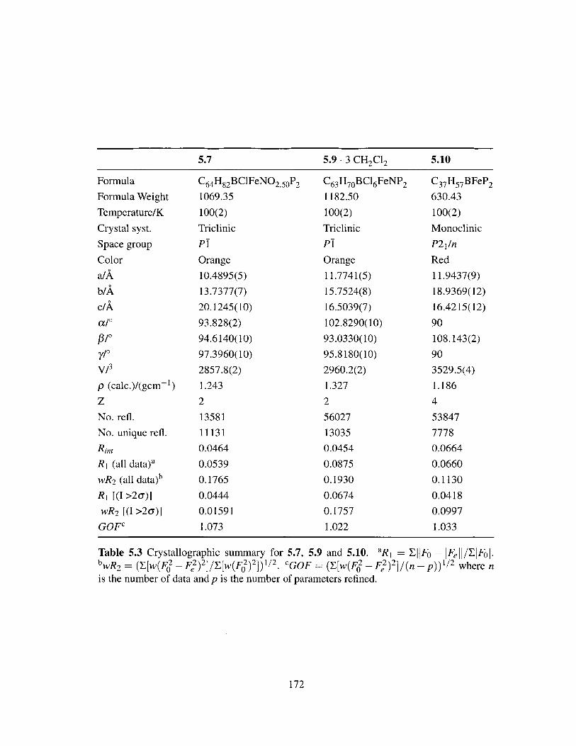
5.7 5.9 . 3 CH 2Cl 2 5.10
Formula
Formula Weight
Temperature/K
Crystal syst.
Space group
Color
a/A
b/A
c/A
a/'
#/0y/
V/3
p (calc.)/(gcm-)
z
No. refl.
No. unique refl.
Rint
R, (all data)a
wR2 (all data)b
R1 [(I >2u)]
wR 2 [(I >2c)]
GOFc
C6 4 H82 BClFeNO 2.5 0P2
1069.35
100(2)
Triclinic
P!
Orange
10.4895(5)
13.7377(7)
20.1245(10)
93.828(2)
94.6140(10)
97.3960(10)
2857.8(2)
1.243
2
13581
11131
0.0464
0.0539
0.1765
0.0444
0.01591
1.073
C63H70BC16FeNP21182.50
100(2)
Triclinic
P!
Orange
11.7741(5)
15.7524(8)
16.5039(7)
102.8290(10)
93.0330(10)
95.8180(10)
2960.2(2)
1.327
2
56027
13035
0.0454
0.0875
0.1930
0.0674
0.1757
1.022
C37 H 57 BFeP 2
630.43
100(2)
Monoclinic
P21/n
Red
11.9437(9)
18.9369(12)
16.4215(12)
90
108.143(2)
90
3529.5(4)
1.186
4
53847
7778
0.0664
0.0660
0.1130
0.0418
0.0997
1.033
172
Table 5.3 Crystallographic summary for 5.7, 5.9 and 5.10. aR 1 = EiFo - IFej/EjFol.bwR 2 = (y[w(F2 - F2)2 ]/ [w(F2)2]) 1/ 2. CGOF [W(F2- F)2 2 where n
is the number of data and p is the number of parameters refined.

5.10 Bibliography
[1] McGrady, G. S.; Guilera, G. Chem. Soc. Rev. 2003, 32, 383-392.
[2] Howard, J. B.; Rees, D. C. Chem. Rev. 1996, 96, 2965-2982.
[3] Burgess, B. K.; Lowe, D. J. Chem. Rev. 1996, 96, 2983-3011.
[4] Eady, R. R. Chem. Rev. 1996, 96, 3013-3030.
[5] Thorneley, R. N. F.; Eady, R. R.; Lowe, D. J. Nature 1978, 272, 557-55 8.
[6] Leigh, G. J.; McMahon, C. N. J. Organomet. Chem. 1995, 500, 219-225.
[7] Igarashi, R. Y.; Laryukhin, M.; Dos Santos, P. C.; Lee, H.-I.; Dean, D. R.;Seefeldt, L. C.; Hoffman, B. M. J. Am. Chem. Soc. 2005, 127, 6231-6241.
[8] Fontecilla-Camps, J. C.; Volbeda, A.; Cavazza, C.; Nicolet, Y Chem. Rev. 2007,107, 4273-4303.
[9] Wright, J. A.; Turrell, P. J.; Pickett, C. J. Organometallics 2010, 29, 6146-6156.
[10] Nakazawa, H.; Itazaki, M. Top. Organomet. Chem. 2011, 33, 27-8 1.
[11] Junge, K.; Schr6der, K.; Beller, M. Chem. Commun. 2011, 47, 4849-4859.
[12] Frankel, E. N.; Emken, E. A.; Peters, H. M.; Davison, V. L.; Butterfield, R. 0. J.Org. Chem. 1964, 29, 3292-3297.
[13] Frankel, E. N.; Emken, E. A.; Davison, V. L. J. Org. Chem. 1965, 30, 2739-2745.
[14] Cais, M.; Maoz, N. J. Chem. Soc. A 1971, 11, 1811-1820.
[15] Schroeder, M. A.; Wrighton, M. S. J. Am. Chem. Soc. 1976, 98, 551-558.
[16] Bianchini, C.; Meli, A.; Peruzzini, M.; Frediani, P.; Bohanna, C.; Esteruelas, M. A.;Oro, L. A. Organometallics 1992, 11, 138-145.
[17] Chiang, K. P.; Scarborough, C. C.; Horitani, M.; Lees, N. S.; Ding, K.; Dugan, T. R.;Brennessel, W. W.; Bill, E.; Hoffman, B. M.; Holland, P. L. Angew. Chem. Int. Ed.2012, 51, 3658-3662.
[18] Yu, Y.; Sadique, A. R.; Smith, J. M.; Dugan, T. R.; Cowley, R. E.; Brennessel, W. W.;Flaschenriem, C. J.; Bill, E.; Cundari, T. R.; Holland, P. L. J. Am. Chem. Soc. 2008,130, 6624-6638.
[19] Bart, S. C.; Lobkovsky, E.; Chirik, P. J. J. Am. Chem. Soc. 2004, 126, 13794-13807.
[20] Bouwkamp, M. W.; Bowman, A. C.; Lobkovsky, E.; Chirik, P. J. J. Am. Chem. Soc.2006,128,13340-13341.
173

[21] Daida, E. J.; Peters, J. C. Inorg. Chem. 2004, 43, 7474-7485.
[22] Brown, S. D.; Peters, J. C. J. Am. Chem. Soc. 2004, 126, 4538-4539.
[23] Betley, T. A.; Peters, J. C. J. Am. Chem. Soc. 2003, 125, 10782-10783.
[24] Brown, S. D.; Betley, T. A.; Peters, J. C. J. Am. Chem. Soc. 2003, 125, 322-323.
[25] Betley, T. A.; Peters, J. C. Inorg. Chem. 2003, 42, 5074-5084.
[26] Akita, M.; Shirasawa, N.; Hikichi, S.; Moro-oka, Y. Chem. Commun. 1998, 973-974.
[27] Fernindez, I.; Trovitch, R. J.; Lobkovsky, E.; Chirik, P. J. Organometallics 2008, 27,109-118.
[28] Popescu, C. V.; Mock, M. T.; Stoian, S. A.; Dougherty, W. G.; Yap, G. P. A.; Rior-dan, C. G. Inorg. Chem. 2009, 48, 8317-8324.
[29] Kisko, J. L.; Hascall, T.; Parkin, G. J. Am. Chem. Soc. 1998, 120, 10561-10562.
[30] Bouwkamp, M. W.; Bart, S. C.; Hawrelak, E. J.; Trovitch, R. J.; Lobkovsky, E.;
Chirik, P. J. Chem. Commun. 2005, 3406-3408.
[31] Jove, F. A.; Pariya, C.; Scoblete, M.; Yap, G. P. A.; Theopold, K. H. Chem. Eur I2011, 17, 1310-1318.
[32] Scott, J.; Gambarotta, S.; Korobkov, I.; Budzelaar, P. H. M. Organometallics 2005,
24, 6298-6300.
[33] Hermes, A. R.; Girolami, G. S. Organometallics 1987, 6, 763-768.
[34] Lee, H. K.; Luo, B.-S.; Mak, T. C. W.; Leung, W.-P. J. Organomet. Chem. 1995,489, C71-C73.
[35] Leung, W.-P.; Lee, H. K.; Weng, L.-H.; Luo, B.-S.; Zhou, Z.-Y; Mak, T. C. W.Organometallics 1996, 15, 1785-1792.
[36] Fryzuk, M. D.; Leznoff, D. B.; Ma, E. S. F.; Rettig, S. J.; Young, V. G., JrOrganometallics 1998, 17, 23 13-2323.
[37] Sciarone, T. J. J.; Meetsma, A.; Hesssen, B.; Teuben, J. H. Chem. Commun. 2002,1580-1581.
[38] Smith, J. M.; Lachicotte, R. J.; Holland, P. L. Organometallics 2002, 21, 4808-4814.
[39] Vela, J.; Vaddadi, S.; Cundari, T. R.; Smith, J. M.; Gregory, E. A.; Lachicotte, R. J.;Flaschenriem, C. J.; Holland, P. L. Organometallics 2004, 23, 5226-5239.
[40] Bart, S. C.; Hawrelak, E. J.; Schmisseur, A. K.; Lobkovsky, E.; Chirik, P. J.Organometallics 2004, 23, 237-246.
174

[41] Bouwkamp, M. W.; Lobkovsky, E.; Chirik, P. J. J. Am. Chem. Soc. 2005, 127, 9660-9661.
[42] Brown, S. D. The chemistry of tris(phosphine)borate supported iron-nitrogenmultiply-bonded linkages. Ph.D. thesis, California Institute of Technology, 2005.
[43] Morris, R. H. Coord. Chem. Rev. 2008, 252, 2381-2394.
[44] Crabtree, R. H.; Lavin, M.; Bonneviot, L. J. Am. Chem. Soc. 1986, 108, 4032-4037.
[45] Hamilton, D. G.; Crabtree, R. H. J. Am. Chem. Soc. 1988, 110, 4126-4133.
[46] Luo, X. L.; Crabtree, R. H. Inorg. Chem. 1990, 29, 2788-2791.
[47] Gusev, D. G.; Hubener, R.; Burger, P.; Orama, 0.; Berke, H. J. Am. Chem. Soc. 1997,119, 3716-3731.
[48] Thomas, J. C.; Peters, J. C. J. Am. Chem. Soc. 2003, 125, 8870-8888.
[49] Betley, T. A.; Peters, J. C. Angew. Chem. Int. Ed. 2003, 42, 2385-2389.
[50] Lu, C. C.; Peters, J. C. J. Am. Chem. Soc. 2002, 124, 5272-5273.
[51] Thomas, J. C.; Peters, J. C. Inorg. Chem. 2003, 42, 5055-5073.
[52] Bill, E. JuIX. http://ewww.mpi-muelheim.mpg.de/bac/logins/bill/julX-en.php.
[53] Smith, J. M.; Lachicotte, R. J.; Holland, P. L. Chem. Commun. 2001, 1542-1543.
[54] Connie C. Lu, while a graduate student in the Peters group at Caltech, carried outpreliminary studies of iron bis(phosphine)borate complexes.
[55] Das, A. K.; Moatazedi, Z.; Mund, G.; Bennet, A. J.; Batchelor, R. J.; Leznoff, D. B.Inorg. Chem. 2007, 46, 366-368.
[56] Cowley, R. E.; Holland, P. L. Inorg. Chem. 2012, 51, 8352-836 1.
[57] Fohlmeister, L.; Liu, S.; Schulten, C.; Moubaraki, B.; Stasch, A.; Cashion, J. D.;Murray, K. S.; Gagliardi, L.; Jones, C. Angew. Chem. Int. Ed. 2012, 51, 8294-8298.
[58] Moatazedi, Z.; Katz, M. J.; Leznoff, D. B. Dalton Trans. 2010, 39, 9889-9896.
[59] Vicente, J.; Shenoy, R. V.; Martinez-Viviente, E.; Jones, P. G. Inorg. Chem. 2011,50, 7189-7194.
[60] Paredes, P.; Difez, J.; Gamasa, M. P Organometallics 2008, 27, 2597-2607.
[61] Davis, K. B.; Harris, T. D.; Castellani, M. P.; Golen, J. A.; Rheingold, A. L.Organometallics 2007, 26, 4843-4845.
175

[62] Kunrath, F. A.; Casagrande, 0. L.; Toupet, L.; Carpentier, J.-F. Eur J. Inorg. Chem.
2004, 2004,4803-4806.
[63] Drouin, S. D.; Foucault, H. M.; Yap, G. P. A.; Fogg, D. E. Organometallics 2004,23, 2583-2590.
[64] Devic, T.; Batail, P.; Fourmigud, M.; Avarvari, N. Inorg. Chem. 2004, 43, 3136-3141.
[65] Szymczak, N. K.; Han, F.; Tyler, D. R. Dalton Trans. 2004, 3941-3942.
[66] Becker, C.; Kieltsch, I.; Broggini, D.; Mezzetti, A. Inorg. Chem. 2003, 42, 8417-8429.
[67] Barthazy, P.; Togni, A.; Mezzetti, A. Organometallics 2001, 20, 3472-3477.
[68] Bianchini, C.; Masi, D.; Linn, K.; Mealli, C.; Peruzzini, M.; Zanobini, F. Inorg.Chem. 1992, 31, 4036-4037.
[69] Kahwa, I. A.; Miller, D.; Mitchel, M.; Fronczek, F. R.; Goodrich, R. G.;Williams, D. J.; O'Mahoney, C. A.; Slawin, A. M. Z.; Ley, S. V.; Groombridge, C. J.Inorg. Chem. 1992, 31, 3963-3970.
[70] Blake, A. J.; Christie, R. M.; Roberts, Y. V.; Sullivan, M. J.; Schr6der, M.; Yel-lowlees, L. J. J. Chem. Soc., Chem. Commun. 1992, 848-850.
[71] Ezomo, 0. J.; Mingos, D. M. P.; Williams, I. D. J. Chem. Soc., Chem. Commun.1987, 924-925.
[72] Evans, D. J.; Hill, M. S.; Hitchcock, P. B. Dalton Trans. 2003, 570-574.
[73] Masuda, J. D.; Stephan, D. W. Can. J. Chem. 2005, 83, 477-484.
[74] Sciarone, T. J. J.; Nijhuis, C. A.; Meetsma, A.; Hessen, B. Dalton Trans. 2006,4896-4904.
[75] Grubba, R.; Ponikiewski, L.; Tomorowicz, L.; Pikies, J. Acta. Crystallogr. Sect. E.
2010, m707-m707.
[76] Rodriguez, M. M.; Bill, E.; Brennessel, W. W.; Holland, P. L. Science 2011, 334,780-783.
[77] Zhang, J.; Gao, W.; Lang, X.; Wu, Q.; Zhang, L.; Mu, Y Dalton Trans. 2012, 41,9639-9645.
[78] Olmstead, M. M.; Power, P. P.; Shoner, S. C. Inorg. Chem. 1991, 30, 2547-2551.
[79] Stokes, S. L.; Davis, W. M.; Odom, A. L.; Cummins, C. C. Organometallics 1996,15, 4521-4530.
176
[80] Eckert, N. A.; Smith, J. M.; Lachicotte, R. J.; Holland, P. L. Inorg. Chem. 2004, 43,3306-3321.
[81] Buschhorn, D.; Pink, M.; Fan, H.; Caulton, K. G. Inorg. Chem. 2008, 47, 5129-5135.
[82] Wang, J.-H.; Chen, C.-H. Inorg. Chem. 2010, 49, 7644-7646.
[83] Betley, T. A.; Peters, J. C. J. Am. Chem. Soc. 2004, 126, 6252-6254.
[84] Saouma, C. T.; Lu, C. C.; Peters, J. C. Inorg. Chem. 2012, 51, 10043-10054.
[85] Sciarone, T. J. J.; Nijhuis, C. A.; Meetsma, A.; Hessen, B. Organometallics 2008,27, 2058-2065.
[86] Vela, J.; Cirera, J.; Smith, J. M.; Lachicotte, R. J.; Flaschenriem, C. J.; Alvarez, S.;Holland, P. L. Inorg. Chem. 2007, 46, 60-71.
[87] Sciarone, T. J. J.; Meetsma, A.; Hessen, B. Inorg. Chim. Acta 2006,359, 1815-1825.
[88] CaImpora, J.; Naz, A. M.; Palma, P.; Alvarez, E.; Reyes, M. L. Organometallics2005, 24, 4878-4881.
[89] Vela, J.; Smith, J. M.; Lachicotte, R. J.; Holland, P. L. Chem. Commun. 2002, 2886-2887.
[90] Shirasawa, N.; Nguyet, T. T.; Hikichi, S.; Moro-oka, Y.; Akita, M. Organometallics2001, 20, 3582-3598.
[91] Kinney, R. A.; Hetterscheid, D. G. H.; Hanna, B. S.; Schrock, R. R.; Hoffman, B. M.Inorg. Chem. 2010, 49, 704-713.
[92] Lee, Y.; Kinney, R. A.; Hoffman, B. M.; Peters, J. C. J. Am. Chem. Soc. 2011, 133,16366-16369.
[93] Thomas, J. C.; Peters, J. C. J. Am. Chem. Soc. 2001, 123, 5100-5 101.
[94] Zechmann, C. A.; Boyle, T. J.; Pedrotty, D. M.; Alam, T. M.; Lang, D. P.; Scott, B. L.Inorg. Chem. 2001, 40, 2177-2184.
[95] Sur, S. K. J. Magn. Reson. 1989, 82, 169-173.
[96] Evans, D. F. J. Chem. Soc. 1959, 2003-2005.
[97] Sheldrick, G. M. Acta Cryst. 1990, A46, 467-473.
[98] Sheldrick, G. M. SHELXL-97: Program for Crystal Structure Refinement. Univer-sity of Gottingen, G6ttingen, Germany, 1997.
[99] Muller, P. Crystallogr. Rev. 2009, 15, 57-83.
177

[100] Dolomanov, 0. V.; Bourhis, L. J.; Gildea, R. J.; Howard, J. A. K.; Puschmann, H. J.
Appl. Cryst. 2009, 42, 339-341.
[101] van der Sluis, P.; Spek, A. L. Acta Cryst. 1990, A46, 194-20 1.
[102] Spek, A. L. Acta Cryst. 2009, D65, 148-155.
178

179