bpix_slate_manual_v8 (1)
TRANSCRIPT
install - concepts - PixMaster - switcher - CG - clips - controls - team - appendix Broadcast Pix V8
Slate 100G / 1000G / 2100G / 3000G 1ME HD & SD Video Switchers Operators Manual
Slate G Series Software Version 8

install - concepts - PixMaster - switcher - CG - clips - controls - team - appendix Broadcast Pix V8 0.1
Made in the United States of America © 2010 Copyright Broadcast Pix, Inc. May 2010 Broadcast Pix, Slate, iBoB, PixButtons, PixMaster, PixPad, AutoAspect, and SoftPanel are trademarks of Broadcast Pix, Inc. Other trademarks are owned by their respective companies.
Warranty on all Slate Switchers
The Products will be of a professional quality, meet the specifications set forth in the Product descriptions and are warranted to be free from defects in materials and workmanship for a period of fourteen (14) months from shipment from Manufacturer. Broadcast Pix will repair or, at its sole option, replace any component found to be faulty on any system returned to the service center of Broadcast Pix in the USA for repair. The costs of any visit to the customer's site are not included in the warranty. The cost of returning Product to Broadcast Pix is the responsibility of the end user or the Dealer. Dealer is authorized to deliver the Broadcast Pix warranty, as described above, to purchasers of the Products and the Future Products. No software is to be added to the product from any other source than Broadcast Pix, unless approved by Broadcast Pix, or it will invalidate this warranty.
BROADCAST PIX MAKES NO OTHER WARRANTY, EXPRESSED OR IMPLIED, AND PARTICULARLY EXCLUDES ANY IMPLIED WARRANTIES OF MERCHANTABILITY OR FITNESS FOR A PARTICULAR PURPOSE.
install - concepts - PixMaster - switcher - CG - clips - controls - team - appendix Broadcast Pix V8
Section 1 Installation and Getting Started
1.1 Video I/O Configurations 1.1.1 Analog Video I/O 1.1.2 HD I/O 1.1.3 Optional DVI-I I/O 1.2 Broadcast Pix Slate 100G 1.2.1 System Contents 1.2.2 Wiring Diagram 1.2.3 Optional Slate 100G Control Panels 1.2.4 Keyboard Shortcuts 1.2.5 Enabling Keyboard Shortcuts 1.2.6 Using Keyboard Shortcuts 1.3 Broadcast Pix Slate 1000G 1.3.1 System Contents 1.3.2 Wiring Diagram 1.3.3 Optional Tally Box Wiring 1.3.4 Installing Tally Box Drivers 1.3.5 Installing Multiple Tally Boxes 1.4 Audio I/O 1.5 Slate I/O Assignments 1.5.1 AutoAspect for Inputs 1.6 Broadcast Pix Slate 2100G 1.6.1 System Contents 1.6.2 Wiring Diagram 1.6.3 iBoB Audio I/O Wiring 1.6.4 iBoB Tally Wiring 1.6.5 iBoB Assignments 1.6.6 Setting up the iBoB from the Control Panel 1.7 Broadcast Pix Slate 3000G 1.7.1 System Contents 1.7.2 Slate 3016Gdd & 3016Ghh Wiring Diagram 1.7.3 Slate 3032Gdd & 3032Ghh Wiring Diagram 1.7.4 Multi-System Control 1.7.5 Example Slate 3032G & Slate 3032G Wiring 1.7.6 Optional Tally Box Wiring 1.7.7 Optional Remote Aux Panel Wiring 1.7.8 Router Assignments 1.7.9 Optional Multi-System Control Assignments
0.1
Table of Contents
install - concepts - PixMaster - switcher - CG - clips - controls - team - appendix Broadcast Pix V8
Section 1 Installation and Getting Started
1.8 Running a Show 1.9 Troubleshooting 1.10 Input Timing & Asynchronous Sources 1.10.1 System Delay 1.11 Changing what show is running 1.12 Settings 1.12.1 Changing the Startup Show 1.12.2 Selecting between NTSC/525 and PAL/625 1.12.3 Selecting between Aspect Ratio 16:9 and 4:3 1.13 DualAspect 1.14 HD Video Detail 1.15 Control Panel Installation 1.16 Premium Workstations 1.16.1 Redundant Power Supplies 1.16.2 Removable Media Drives 1.16.3 Back-Up Software
0.2
Table of Contents
install - concepts - PixMaster - switcher - CG - clips - controls - team - appendix Broadcast Pix V8
Section 2 Broadcast Pix Concepts
2.1 Broadcast Pix Switcher Features 2.1.1 Video Flow Diagram 2.2 PixButtons for Executing with Confidence 2.3 Devices 2.4 Device Controls 2.4.1 Assigning the Device Controls 2.4.2 PixPad Navigation 2.4.3 Multi-View PixPad 2.4.4 PixPad Order Controls 2.4.5 Floating PixPads 2.5 Multi-View 2.5.1 Overview of the Multi-View 2.5.2 Sources on Multi-View 2.5.3 Keyer on the Multi-View 2.5.4 Program/Preview Overlays on the Multi-View 2.5.5 Clip Store Counters 2.5.6 Basic Switching on the Multi-View 2.5.7 Advanced Switching on the Multi-View 2.5.8 Floating Monitors 2.5.9 Clocks on the Multi-View 2.6 List of Screen Resolutions 2.6.1 Adjusting the Windows Desktop Screen Resolution 2.6.2 Optional Quad Monitor Card
0.3
Table of Contents
install - concepts - PixMaster - switcher - CG - clips - controls - team - appendix Broadcast Pix V8 0.4
Table of Contents
Section 3 PixMaster Show Editor
3.0 PixMaster Storage System 3.1 Creating a New Show 3.2 Selecting an Existing Show to Edit 3.3 Editing a Show 3.4 Editing a Show’s Content 3.5 Reordering, Adding or Removing Content 3.5.1 To Reorder Content 3.5.2 To Reorder a Group of Content 3.5.3 Adding content from the central Library 3.5.4 Adding a group of content from the central library 3.5.5 Manually Importing Content 3.5.6 Importing a Content into a Subfolder 3.5.7 Fluent Watch Folders 3.5.8 Resizing and Softening Images 3.5.9 Previewing Content 3.5.10 Renaming Content 3.5.11 Removing Content from a Show 3.5.12 Permanently Deleting Content from the Library 3.6 Show Content Summary 3.7 Editing Show Settings 3.7.1 Switcher Source Assignments 3.7.2 Auto Fail-Safe Setting 3.7.3 Adding Wildcard Devices 3.7.4 Show Memories 3.7.5 Global Naming of Memories 3.7.6 Custom Images on Memory PixButtons 3.8 Tally Remapping
install - concepts - PixMaster - switcher - CG - clips - controls - team - appendix Broadcast Pix V8
Section 4 Production Switcher
4.0 Switcher Controls 4.0.1 Tally 4.1 Video Sources 4.1.1 Accessing Inputs 10-18 with Shift 4.1.2 Lock Shift 4.2 Transitions 4.2.1 Transition Preview 4.2.2 Background Cut Transition 4.2.3 Background Mix Transition 4.2.4 Background Effects Transition 4.3 Transition Effects 4.3.1 Effects Styles and PixButtons 4.3.2 Selecting a New Effect by Number 4.3.3 Changing Effect Transition Rates 4.3.4 Reversing an Effect 4.3.5 Modifying an Effect 4.4 Keys 4.4.1 Key Controls 4.4.2 Assigning a Source to Keys 1-3 4.4.3 Direct Keys Control 4.4.4 Transitioning Keys with other keys or with the Background 4.4.5 Pro Transition Mode 4.4.6 Modifiers for Keyers 4.4.7 To Change the Key Fade Rate 4.5 DVE Boxes (Picture in Picture) 4.5.1 To Create a DVE Box: 4.5.2 Modifying a DVE Box 4.5.3 Dual and Triple DVE Boxes 4.5.4 Accessing Keys 4-6 4.6 Source Controls 4.7 Chromakey 4.7.1 Activating the Chromakey 4.7.2 Settings for the Chromakey 4.7.3 Adjusting the Chromakey 4.8 Luma Key 4.8.1 Activating & Adjusting the Luma key
0.5
Table of Contents
install - concepts - PixMaster - switcher - CG - clips - controls - team - appendix Broadcast Pix V8
Section 4 Production Switcher
4.9 External Key 4.9.1 To Setup External Key 4.9.2 To Operate External Key 4.9.3 iBoB DSK Downstream on Slate 2100G 4.9.4 To Enable/Disable iBoB DSK 4.9.5 To Turn On & Set Up iBoB DSK 4.9.6 To Operate & Modify iBoB DSK 4.10 Auxiliary Output Control 4.10.1 Aux Out on Slate 100G & 1000G 4.10.2 Aux Out on Slate 2100G 4.10.3 Aux Out on Slate 3016G 4.10.4 Aux Out on Slate 3032G 4.10.5 Assigning Output Sources 4.10.6 Remote Aux Panel on Slate 3016/3032 4.10.7 Programming the Remote Aux Panel 4.10.8 PowerAux Control 4.11 SnapShot Memories 4.11.1 Saving a Mem 4.11.2 Recalling a Mem 4.11.3 Recalling a Mem by number 4.12 Fluent Macros 4.12.1 Opening the Macros Interface 4.12.2 Recording a Macro 4.12.3 Editing a Macro 4.12.4 Inserting Actions 4.12.5 Reviewing Macro 4.12.6 Assigning Macros in the Macro Player 4.12.7 Running Macros in the Macro Player 4.12.8 Playing back files not in shows 4.12.9 Alpha Wipes 4.13 Fail-Safe On-Air Production 4.13.1 Fail-Safe on Slate 100G and Slate 1000G 4.13.2 Fail-Safe on Slate 2100G & 3000G 4.13.3 Fail-Safe Operation on Slate 2100G 4.13.4 Fail-Safe Operation on Slate 3000G 4.14 Capture of Stills 4.14.1 Capturing an Image 4.14.2 Capture Folder Destination
0.6
Table of Contents
install - concepts - PixMaster - switcher - CG - clips - controls - team - appendix Broadcast Pix V8 0.7
Section 5 CG and Graphics
5.1 CG Installation 5.1.1 TitleMotion Pro Canvas 5.2 Creating Still CG Graphics 5.2.1 Exporting a Still Graphic from Inscriber to Broadcast Pix 5.2.2 Exporting Graphics from Photoshop to Broadcast Pix 5.3 CG Rolls and Crawls 5.3.1 To Create CG Graphics that Roll or Crawl 5.3.2 To Play a Roll or Crawl 5.3.3 Motion Controls for Rolls and Crawls 5.3.4 Modifiers for Rolls and Crawls 5.4 Creating an Animated CG Graphic 5.4.1 To Create an Animated Graphic 5.4.2 Importing an Animated CG Graphic into Broadcast Pix 5.4.3 On-Air Operations for CG Animations 5.4.4 Creating Animations in 3rd Party Applications 5.5 Basic CG On-Air Operation 5.6 Updating CG Graphics On-the-Fly 5.6.1 .ICG Editing 5.6.2 Overwriting a File 5.7 Dual CG 5.8 Still Store and Logo Operation 5.8.1 Preparing Still Content 5.9 Optional CG Connect Software 5.9.1 Adding the RTX Tags 5.9.2 Loading CG Connect with a Layout 5.9.3 Updating the CG Layout 5.9.4 Adding a Data Source with XML Files 5.9.5 Creating your Own XML File 5.9.6 Using Images with CG Connect 5.9.7 Using Clocks with CG Connect 5.9.8 Displaying the CG Layout 5.10 Using International Characters with Inscriber
Table of Contents
install - concepts - PixMaster - switcher - CG - clips - controls - team - appendix Broadcast Pix V8
Section 6 Clip Store
6.0.1 Audio Flow with Embedded Audio 6.0.2 Audio Flow with Digital AES/EBU Audio 6.0.3 Audio Flow with Analog Stereo Audio 6.0.4 Clip Audio Advance 6.1 Recording a Clip 6.2 Clip Store Playout 6.2.1 To Select a Clip by Name 6.2.2 To Select a Clip by Number 6.2.3 Selecting a Clip with the Multi-View 6.2.4 Viewing More Clips in the Library 6.2.5 Creating Clip Thumbnails 6.3 Clip Motion Controls 6.3.1 Clip Counter 6.4 Clip Modifiers 6.4.1 Mark In and Out Points 6.4.2 Auto Start Clips 6.4.3 Auto Stop Clips 6.4.4 Auto Rewind Clips 6.4.5 Loop Clips 6.4.6 AutoAspect Controls 6.4.7 Scrubbing a Clip 6.5 Playback of Compressed Clips 6.5.1 Exporting Compressed Clips from Final Cut Pro 6.6 Optional Dual Clip Store 6.7 Optional External DDR Control 6.7.1 Installing External DDR Control 6.7.2 Verifying Installation of External DDR Control 6.7.3 Selecting Clips to Access 6.7.4 Adding DDR Control to a Show 6.7.5 Controlling External DDR 6.7.6 DDR Controls 6.7.7 Accessing More Channels
0.8
Table of Contents
install - concepts - PixMaster - switcher - CG - clips - controls - team - appendix Broadcast Pix V8
Section 7 Optional Device Controls
7.1 Camera Control Option 7.2 Installation of Sony Cameras 7.2.1 Sony Wiring Configurations 7.3 Installation of Hitachi Cameras 7.3.1 One Camera Installation 7.3.2 Multi-Camera Installation 7.4 Installation of Panasonic Cameras 7.4.1 Panasonic Wiring Configurations 7.5 Installation of Telemetrics Camera Systems 7.5.1 Telemetrics Wiring Configurations 7.6 Adding Camera Control Option to an Existing System 7.7 Camera Control Device Settings 7.7.1 Sony Camera Control Settings 7.7.2 Hitachi Camera Control Settings 7.7.3 Setting the Camera Numbers for Hitachi Camera Control 7.7.4 Panasonic Camera Control Settings 7.7.5 Telemetrics Camera Control Settings 7.8 Adding Camera Control to a Show 7.9 Selecting Camera Control in a Production 7.10 Controlling a Camera Manually 7.10.1 Motion Controls for Hitachi Camera Control 7.10.2 Motion Controls for Panasonic Camera Control 7.10.3 Motion Controls for Telemetrics Camera Control 7.11 Setting Camera Preset Positions 7.11.1 Recalling Preset Camera Positions 7.11.2 Recall Speed for Hitachi Preset Positions 7.12 Hitachi Camera Control Settings 7.12.1 Travel Limits of Tilt and Pan 7.12.2 Adjusting CCU Functions 7.13 Sony Camera Control Settings 7.13.1 Adjusting CCU Functions 7.14 Panasonic Camera Control Settings 7.14.1 Adjusting CCU Functions 7.15 Telemetrics Camera Control Settings 7.15.1 Adjusting CCU Functions
0.9
Table of Contents
install - concepts - PixMaster - switcher - CG - clips - controls - team - appendix Broadcast Pix V8
Section 7 Device Controls Continued
7.16 Optional Audio-Follow-Video Control 7.16.1 Enabling Audio Follow 7.16.2 Activating Audio Follow 7.16.3 Audio Follow Setup 7.16.4 Audio Follow Operation 7.17 Streamer Control 7.17.1 Installing Streamer Control 7.17.2 Adding Streamer Control to a Show 7.17.3 Streamer Control Settings 7.17.4 Selecting Streamer Control in a Production 7.14.5 Controlling a Streamer Group
Section 8 Team Operation
8.1 Optional Multi-Panel Support 8.2 Opening a SoftPanel 8.3 Locking Panels Together 8.4 Viewing just a portion of the SoftPanel 8.5 Adding a Separate Graphics Operator 8.5.1 Two Operators with Separate Graphics Operator and 1 Panel 8.5.2 Two Operators with Separate Graphics Operator and 2 Panels 8.6 Two Operators with Two Computers 8.7 Remote Operator in the Back Room 8.8 Dual Panels for Back-Up Redundancy 8.9 Remote Control from a Distance 8.10 Remote Control from an iPhone/iPod/iPad
0.10
Table of Contents
install - concepts - PixMaster - switcher - CG - clips - controls - team - appendix Broadcast Pix V8
Appendix
A.1 Updating the Software to Future Versions A.2 Installing System Options A.3 Control Panel Internal Operation A.4 Broadcast Pix Slate Analog Video Connector Pin-Outs A.5 Broadcast Pix Slate Analog Audio Breakout Cable A.6 RS-232 Serial Pin-Out for Slate 2100, 3016 3032 Fail-Safe Control A.7 Broadcast Pix Slate Technical Specifications A.8 Custom Shortcuts Keyboard Layout A.9 Glossary A.10 Broadcast Pix Contact Information
0.11
Table of Contents
install - concepts - PixMaster - switcher - CG - clips - controls - team - appendix Broadcast Pix V8
Thank you for purchasing a Broadcast Pix Slate video switcher, soon you will be experiencing how we have redefined the switcher.
There are a total of 25 Slate switcher models, as shown below, all of which use the same BP Switcher software, each with unique hardware to control the software.
Take note to which model you have purchased and refer to that section in this manual prior to installing your Broadcast Pix Switcher.
Slate Configurations:
1.0
Section 1: Installation and Getting Started
There are 9 Slate 100G configurations:
Slate HD Slate SD 100Gh 100Ga 100Ghh 100Gd 100Gha 100Gaa 100Ghd 100Gdd
100Gda
There are 9 Slate 1000G configurations:
Slate HD Slate SD 1000Gh 1000Ga 1000Ghh 1000Gd 1000Gha 1000Gaa 1000Ghd 1000Gdd
1000Gda
There are 3 Slate 2100G configurations:
Slate HD Slate SD 2100Gdh 2100Gda
2100Gdd
There are 4 Slate 3000G configurations:
Slate HD Slate SD 3016Ghh 3016Gdd 3032Ghh 3032Gdd
install - concepts - PixMaster - switcher - CG - clips - controls - team - appendix Broadcast Pix V8
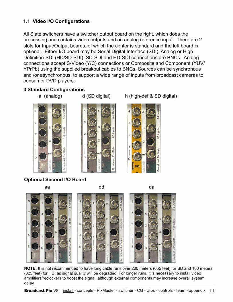
All Slate switchers have a switcher output board on the right, which does the processing and contains video outputs and an analog reference input. There are 2 slots for Input/Output boards, of which the center is standard and the left board is optional. Either I/O board may be Serial Digital Interface (SDI), Analog or High Definition-SDI (HD/SD-SDI). SD-SDI and HD-SDI connections are BNCs. Analog connections accept S-Video (Y/C) connections or Composite and Component (YUV/YPrPb) using the supplied breakout cables to BNCs. Sources can be synchronous and /or asynchronous, to support a wide range of inputs from broadcast cameras to consumer DVD players.
1.1 Video I/O Configurations
Optional Second I/O Board
a (analog) d (SD digital) h (high-def & SD digital) 3 Standard Configurations
aa dd da
1.1
NOTE: It is not recommended to have long cable runs over 200 meters (655 feet) for SD and 100 meters (325 feet) for HD, as signal quality will be degraded. For longer runs, it is necessary to install video amplifiers/reclockers to boost the signal, although external components may increase overall system delay.
install - concepts - PixMaster - switcher - CG - clips - controls - team - appendix Broadcast Pix V8
1.1 Video I/O Configurations Continued
1.1
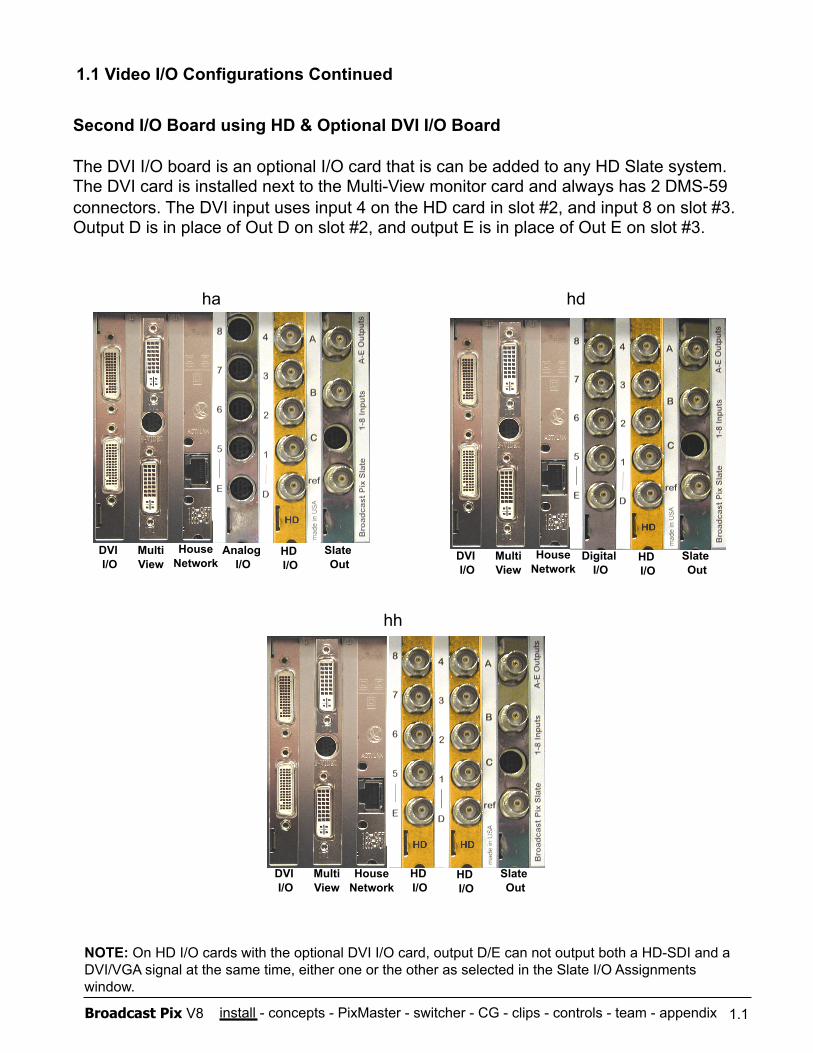
Second I/O Board using HD & Optional DVI I/O Board
The DVI I/O board is an optional I/O card that is can be added to any HD Slate system. The DVI card is installed next to the Multi-View monitor card and always has 2 DMS-59 connectors. The DVI input uses input 4 on the HD card in slot #2, and input 8 on slot #3. Output D is in place of Out D on slot #2, and output E is in place of Out E on slot #3.
hh
ha hd
NOTE: On HD I/O cards with the optional DVI I/O card, output D/E can not output both a HD-SDI and a DVI/VGA signal at the same time, either one or the other as selected in the Slate I/O Assignments window.
DVI I/O
Multi View
House Network
Analog I/O
HD I/O
Slate Out
DVI I/O
Multi View
House Network
Digital I/O
HD I/O
Slate Out
DVI I/O
Multi View
House Network
HD I/O
HD I/O
Slate Out
install - concepts - PixMaster - switcher - CG - clips - controls - team - appendix Broadcast Pix V8
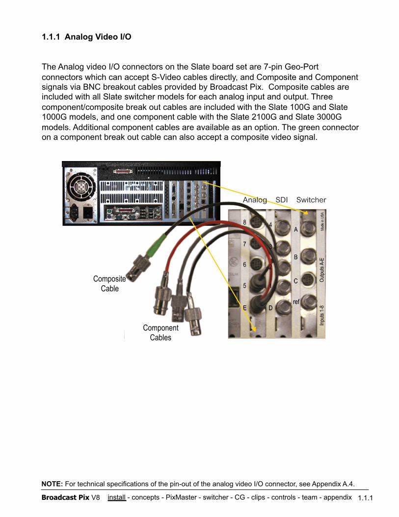
1.1.1 Analog Video I/O
The Analog video I/O connectors on the Slate board set are 7-pin Geo-Port connectors which can accept S-Video cables directly, and Composite and Component signals via BNC breakout cables provided by Broadcast Pix. Composite cables are included with all Slate switcher models for each analog input and output. Three component/composite break out cables are included with the Slate 100G and Slate 1000G models, and one component cable with the Slate 2100G and Slate 3000G models. Additional component cables are available as an option. The green connector on a component break out cable can also accept a composite video signal.
Composite Cable
Component Cables
1.1.1
NOTE: For technical specifications of the pin-out of the analog video I/O connector, see Appendix A.4.
install - concepts - PixMaster - switcher - CG - clips - controls - team - appendix Broadcast Pix V8
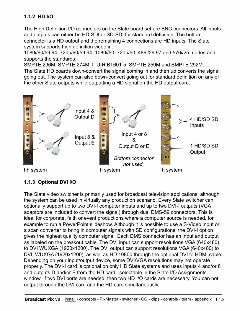
1.1.2 HD I/O
The High Definition I/O connectors on the Slate board set are BNC connectors. All inputs and outputs can either be HD-SDI or SD-SDI for standard definition. The bottom connector is a HD output and the remaining 4 connections are HD inputs. The Slate system supports high definition video in: 1080i/60/59.94, 720p/60/59.94, 1080i/50, 720p/50, 486i/29.97 and 576i/25 modes and supports the standards: SMPTE 296M, SMPTE 274M, ITU-R BT601-5, SMPTE 259M and SMPTE 292M. The Slate HD boards down-convert the signal coming in and then up converts the signal going out. The system can also down-convert going out for standard definition on any of the other Slate outputs while outputting a HD signal on the HD output card.
hh system h system h system
1.1.3 Optional DVI I/O
The Slate video switcher is primarily used for broadcast television applications, although the system can be used in virtually any production scenario. Every Slate switcher can optionally support up to two DVI-I computer inputs and up to two DVI-I outputs (VGA adaptors are included to convert the signal) through dual DMS-59 connectors. This is ideal for corporate, faith or event productions where a computer source is needed, for example to run a PowerPoint slideshow. Although it is possible to use a S-Video input or a scan converter to bring in computer signals with SD configurations, the DVI-I option gives the highest quality computer signal. Each DMS connector has an input and output as labeled on the breakout cable. The DVI input can support resolutions VGA (640x480) to DVI WUXGA (1920x1200). The DVI output can support resolutions VGA (640x480) to DVI WUXGA (1920x1200), as well as HD 1080p through the optional DVI to HDMI cable. Depending on your input/output device, some DVI/VGA resolutions may not operate properly. The DVI-I card is optional on only HD Slate systems and uses inputs 4 and/or 8 and outputs D and/or E from the HD card, selectable in the Slate I/O Assignments window. If two DVI ports are needed, then two HD I/O cards are necessary. You can not output through the DVI card and the HD card simultaneously.
1.1.2
4 HD/SD SDI Inputs
1 HD/SD SDI Output
Input 4 & Output D
Input 8 & Output E
Input 4 or 8 &
Output D or E
Bottom connector not used.
install - concepts - PixMaster - switcher - CG - clips - controls - team - appendix Broadcast Pix V8
1.2 Broadcast Pix Slate 100G
This section covers the typical installation of a Broadcast Pix Slate system and some options. Other options that require installation are covered in their sections.
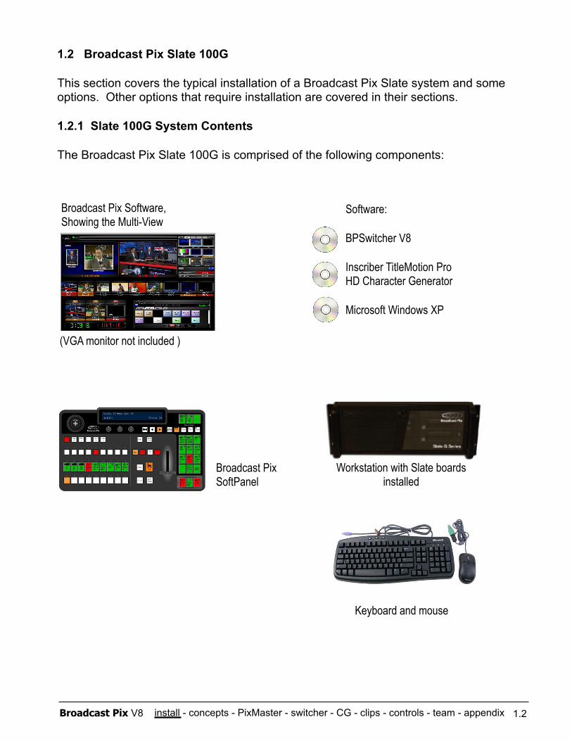
1.2.1 Slate 100G System Contents
The Broadcast Pix Slate 100G is comprised of the following components:
Software:
BPSwitcher V8
Inscriber TitleMotion Pro HD Character Generator
Microsoft Windows XP
Broadcast Pix Software, Showing the Multi-View
Workstation with Slate boards installed
Broadcast Pix SoftPanel
1.2
Keyboard and mouse
(VGA monitor not included )
install - concepts - PixMaster - switcher - CG - clips - controls - team - appendix Broadcast Pix V8
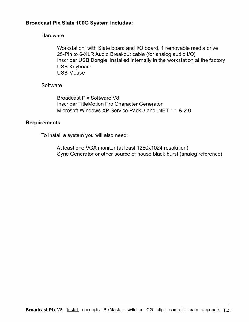
Broadcast Pix Slate 100G System Includes:
Hardware Workstation, with Slate board and I/O board, 1 removable media drive 25-Pin to 6-XLR Audio Breakout cable (for analog audio I/O) Inscriber USB Dongle, installed internally in the workstation at the factory USB Keyboard USB Mouse
Software
Broadcast Pix Software V8 Inscriber TitleMotion Pro Character Generator Microsoft Windows XP Service Pack 3 and .NET 1.1 & 2.0
Requirements
To install a system you will also need:
At least one VGA monitor (at least 1280x1024 resolution) Sync Generator or other source of house black burst (analog reference)
1.2.1
install - concepts - PixMaster - switcher - CG - clips - controls - team - appendix Broadcast Pix V8
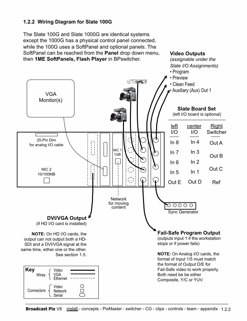
1.2.2 Wiring Diagram for Slate 100G
The Slate 100G and Slate 1000G are identical systems except the 1000G has a physical control panel connected, while the 100G uses a SoftPanel and optional panels. The SoftPanel can be reached from the Panel drop down menu, then 1ME SoftPanels, Flash Player in BPswitcher.
Sync Generator
1.2.2
Network for moving
content
Video VGA Ethernet
Video Network Serial
Wires
Connectors
Out A
Out B
Out C
Ref
Right Switcher
Key
In 4
In 3
In 2
In 1
Out D
center I/O
Fail-Safe Program Output (outputs input 1 if the workstation stops or if power fails)
NOTE: On Analog I/O cards, the format of Input 1/5 must match the format of Output D/E for Fail-Safe video to work properly. Both need be be either Composite, Y/C or YUV.
NIC 2 10/100MB
NIC 1 1GB
In 8
In 7
In 6
In 5
Out E
left I/O
VGA Monitor(s)
Slate Board Set (left I/O board is optional)
Video Outputs (assignable under the Slate I/O Assignments) • Program • Preview • Clean Feed • Auxiliary (Aux) Out 1
DVI/VGA Output (if HD I/O card is installed)
NOTE: On HD I/O cards, the output can not output both a HD-SDI and a DVI/VGA signal at the
same time, either one or the other. See section 1.5.
25-Pin Dim for analog I/O cable
install - concepts - PixMaster - switcher - CG - clips - controls - team - appendix Broadcast Pix V8
1.2.3 Optional Slate 100G Control Panels
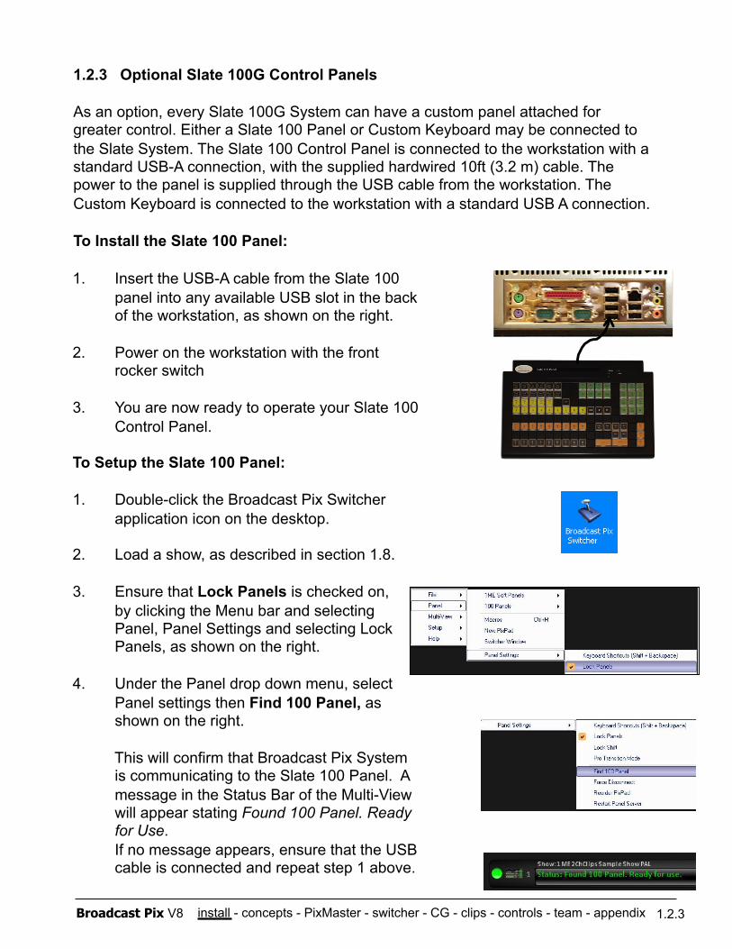
As an option, every Slate 100G System can have a custom panel attached for greater control. Either a Slate 100 Panel or Custom Keyboard may be connected to the Slate System. The Slate 100 Control Panel is connected to the workstation with a standard USB-A connection, with the supplied hardwired 10ft (3.2 m) cable. The power to the panel is supplied through the USB cable from the workstation. The Custom Keyboard is connected to the workstation with a standard USB A connection.
To Install the Slate 100 Panel:
1.2.3
1. Insert the USB-A cable from the Slate 100 panel into any available USB slot in the back of the workstation, as shown on the right.
2. Power on the workstation with the front rocker switch
3. You are now ready to operate your Slate 100 Control Panel.
To Setup the Slate 100 Panel:
1. Double-click the Broadcast Pix Switcher application icon on the desktop.
2. Load a show, as described in section 1.8.
3. Ensure that Lock Panels is checked on, by clicking the Menu bar and selecting Panel, Panel Settings and selecting Lock Panels, as shown on the right.
4. Under the Panel drop down menu, select Panel settings then Find 100 Panel, as shown on the right.
This will confirm that Broadcast Pix System is communicating to the Slate 100 Panel. A message in the Status Bar of the Multi-View will appear stating Found 100 Panel. Ready for Use. If no message appears, ensure that the USB cable is connected and repeat step 1 above.
install - concepts - PixMaster - switcher - CG - clips - controls - team - appendix Broadcast Pix V8
The Broadcast Pix Multi-View complements the Slate 100 Control Panel by providing floating windows for the Panel PixPad and Display to assist in content selection and normal switcher operation. These windows can be saved and recalled, similar to other windows in Broadcast Pix, as described in section 2.5.8. Each window is resizable and takes up a Panel License, a normal Slate 100 system has 2 available Panel Licenses, if more licenses are needed for your system please contact Broadcast Pix Sales.
1.2.3
To Float 100 Panel windows:
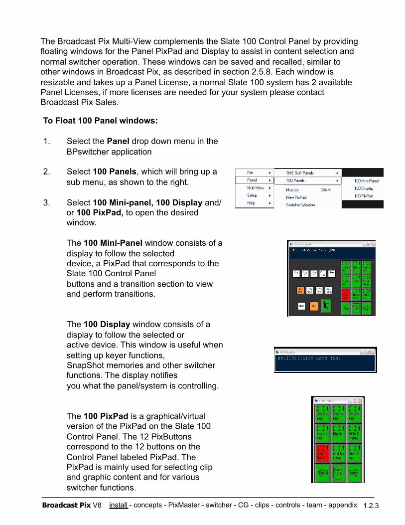
1. Select the Panel drop down menu in the BPswitcher application
2. Select 100 Panels, which will bring up a sub menu, as shown to the right.
3. Select 100 Mini-panel, 100 Display and/or 100 PixPad, to open the desired window.
The 100 Mini-Panel window consists of a display to follow the selected device, a PixPad that corresponds to the Slate 100 Control Panel buttons and a transition section to view and perform transitions.
The 100 Display window consists of a display to follow the selected or active device. This window is useful when setting up keyer functions, SnapShot memories and other switcher functions. The display notifies you what the panel/system is controlling.
The 100 PixPad is a graphical/virtual version of the PixPad on the Slate 100 Control Panel. The 12 PixButtons correspond to the 12 buttons on the Control Panel labeled PixPad. The PixPad is mainly used for selecting clip and graphic content and for various switcher functions.
install - concepts - PixMaster - switcher - CG - clips - controls - team - appendix Broadcast Pix V8
1.2.4 Keyboard Shortcuts
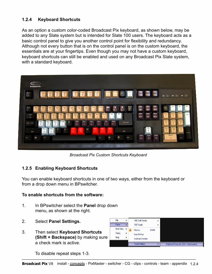
As an option a custom color-coded Broadcast Pix keyboard, as shown below, may be added to any Slate system but is intended for Slate 100 users. The keyboard acts as a basic control panel to give you another control point for flexibility and redundancy. Although not every button that is on the control panel is on the custom keyboard, the essentials are at your fingertips. Even though you may not have a custom keyboard, keyboard shortcuts can still be enabled and used on any Broadcast Pix Slate system, with a standard keyboard.
1.2.5 Enabling Keyboard Shortcuts
You can enable keyboard shortcuts in one of two ways, either from the keyboard or from a drop down menu in BPswitcher.
To enable shortcuts from the software:
1. In BPswitcher select the Panel drop down menu, as shown at the right.
2. Select Panel Settings.
3. Then select Keyboard Shortcuts (Shift + Backspace) by making sure
a check mark is active.
To disable repeat steps 1-3.
1.2.4
Broadcast Pix Custom Shortcuts Keyboard
install - concepts - PixMaster - switcher - CG - clips - controls - team - appendix Broadcast Pix V8
To enable shortcuts from the keyboard:
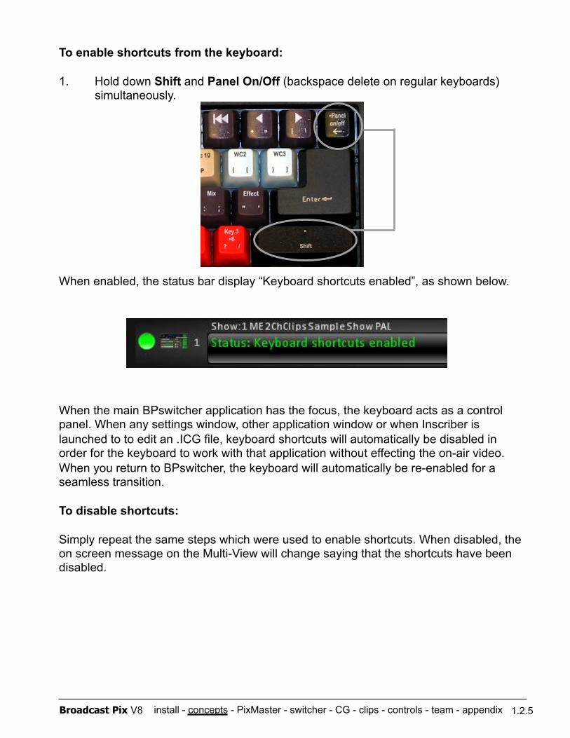
1. Hold down Shift and Panel On/Off (backspace delete on regular keyboards) simultaneously.
When enabled, the status bar display “Keyboard shortcuts enabled”, as shown below.
When the main BPswitcher application has the focus, the keyboard acts as a control panel. When any settings window, other application window or when Inscriber is launched to to edit an .ICG file, keyboard shortcuts will automatically be disabled in order for the keyboard to work with that application without effecting the on-air video. When you return to BPswitcher, the keyboard will automatically be re-enabled for a seamless transition.
To disable shortcuts:
Simply repeat the same steps which were used to enable shortcuts. When disabled, the on screen message on the Multi-View will change saying that the shortcuts have been disabled.
1.2.5
install - concepts - PixMaster - switcher - CG - clips - controls - team - appendix Broadcast Pix V8
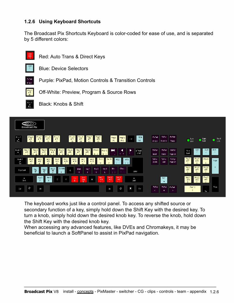
1.2.6 Using Keyboard Shortcuts
The Broadcast Pix Shortcuts Keyboard is color-coded for ease of use, and is separated by 5 different colors:
Red: Auto Trans & Direct Keys
Blue: Device Selectors
Purple: PixPad, Motion Controls & Transition Controls
Off-White: Preview, Program & Source Rows
Black: Knobs & Shift
The keyboard works just like a control panel. To access any shifted source or secondary function of a key, simply hold down the Shift Key with the desired key. To turn a knob, simply hold down the desired knob key. To reverse the knob, hold down the Shift Key with the desired knob key. When accessing any advanced features, like DVEs and Chromakeys, it may be beneficial to launch a SoftPanel to assist in PixPad navigation.
1.2.6
install - concepts - PixMaster - switcher - CG - clips - controls - team - appendix Broadcast Pix V8
Broadcast Pix Control Panel
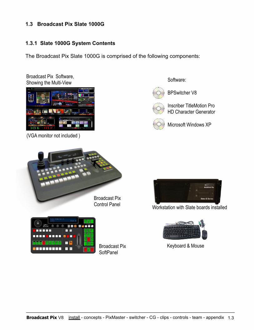
1.3 Broadcast Pix Slate 1000G
1.3.1 Slate 1000G System Contents
The Broadcast Pix Slate 1000G is comprised of the following components:
Software:
BPSwitcher V8
Inscriber TitleMotion Pro HD Character Generator
Microsoft Windows XP
Broadcast Pix Software, Showing the Multi-View
Keyboard & Mouse Broadcast Pix SoftPanel
1.3
Workstation with Slate boards installed
(VGA monitor not included )

install - concepts - PixMaster - switcher - CG - clips - controls - team - appendix Broadcast Pix V8
Broadcast Pix Slate 1000G System Includes:
Hardware Broadcast Pix Control Panel Workstation, with Slate board and I/O board, 1 removable media drive
Network Crossover Cable (to connect panel to workstation) 25-Pin to 6-XLR Audio Breakout cable (for analog audio I/O) Inscriber USB Dongle, installed internally in the workstation at the factory USB Keyboard USB Mouse
Software
Broadcast Pix Software V8 Inscriber TitleMotion Pro Character Generator Microsoft Windows XP Service Pack 3 and .NET 1.1 & 2.0
Requirements
To install a system you will also need:
At least one VGA monitor (at least 1280x1024 resolution) Sync Generator or other source of house black burst (analog reference)
1.3.1
install - concepts - PixMaster - switcher - CG - clips - controls - team - appendix Broadcast Pix V8
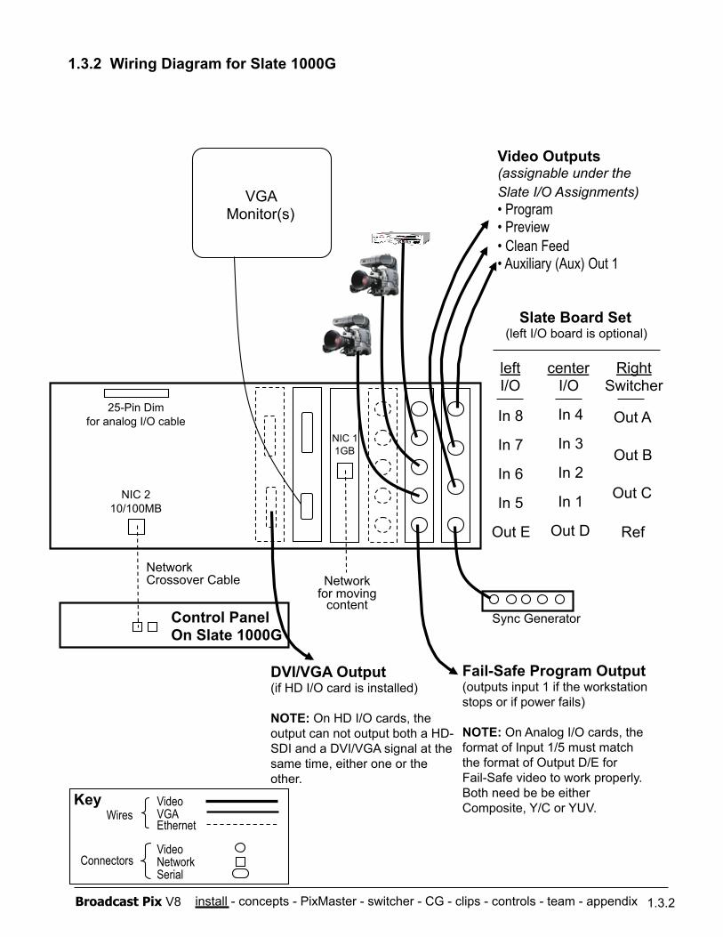
1.3.2 Wiring Diagram for Slate 1000G
Network Crossover Cable
Sync Generator
1.3.2
Network for moving
content
Out A
Out B
Out C
Ref
Control Panel On Slate 1000G
Right Switcher
In 4
In 3
In 2
In 1
Out D
center I/O
Fail-Safe Program Output (outputs input 1 if the workstation stops or if power fails)
NOTE: On Analog I/O cards, the format of Input 1/5 must match the format of Output D/E for Fail-Safe video to work properly. Both need be be either Composite, Y/C or YUV.
NIC 2 10/100MB
NIC 1 1GB
In 8
In 7
In 6
In 5
Out E
left I/O
VGA Monitor(s)
Slate Board Set (left I/O board is optional)
Video Outputs (assignable under the Slate I/O Assignments) • Program • Preview • Clean Feed • Auxiliary (Aux) Out 1
Video VGA Ethernet
Video Network Serial
Wires
Connectors
Key
DVI/VGA Output (if HD I/O card is installed)
NOTE: On HD I/O cards, the output can not output both a HD-SDI and a DVI/VGA signal at the same time, either one or the other.
25-Pin Dim for analog I/O cable
install - concepts - PixMaster - switcher - CG - clips - controls - team - appendix Broadcast Pix V8 1.3.3
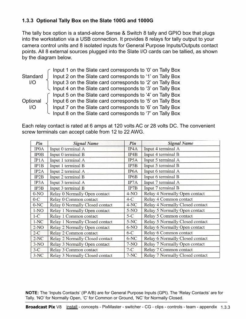
1.3.3 Optional Tally Box on the Slate 100G and 1000G
The tally box option is a stand-alone Sense & Switch 8 tally and GPIO box that plugs into the workstation via a USB connection. It provides 8 relays for tally output to your camera control units and 8 isolated inputs for General Purpose Inputs/Outputs contact points. All 8 external sources plugged into the Slate I/O cards can be tallied, as shown by the diagram below.
Input 1 on the Slate card corresponds to ‘0’ on Tally Box Standard Input 2 on the Slate card corresponds to ‘1’ on Tally Box I/O Input 3 on the Slate card corresponds to ‘2’ on Tally Box
Input 4 on the Slate card corresponds to ‘3’ on Tally Box Input 5 on the Slate card corresponds to ‘4’ on Tally Box
Optional Input 6 on the Slate card corresponds to ‘5’ on Tally Box I/O Input 7 on the Slate card corresponds to ‘6’ on Tally Box
Input 8 on the Slate card corresponds to ‘7’ on Tally Box
Each relay contact is rated at 6 amps at 120 volts AC or 28 volts DC. The convenient screw terminals can accept cable from 12 to 22 AWG.
NOTE: The ‘Inputs Contacts’ (IP A/B) are for General Purpose Inputs (GPI). The ‘Relay Contacts’ are for Tally. ‘NO’ for Normally Open, ‘C’ for Common or Ground, ‘NC’ for Normally Closed.
install - concepts - PixMaster - switcher - CG - clips - controls - team - appendix Broadcast Pix V8 1.3.3
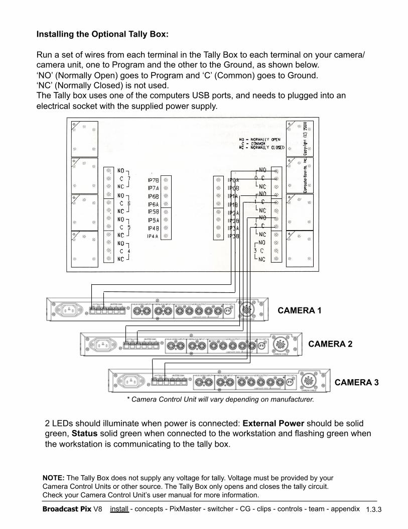
Installing the Optional Tally Box:
Run a set of wires from each terminal in the Tally Box to each terminal on your camera/camera unit, one to Program and the other to the Ground, as shown below. ‘NO’ (Normally Open) goes to Program and ‘C’ (Common) goes to Ground. ‘NC’ (Normally Closed) is not used. The Tally box uses one of the computers USB ports, and needs to plugged into an electrical socket with the supplied power supply.
NOTE: The Tally Box does not supply any voltage for tally. Voltage must be provided by your Camera Control Units or other source. The Tally Box only opens and closes the tally circuit. Check your Camera Control Unit’s user manual for more information.
* Camera Control Unit will vary depending on manufacturer.
CAMERA 1
CAMERA 2
CAMERA 3
2 LEDs should illuminate when power is connected: External Power should be solid green, Status solid green when connected to the workstation and flashing green when the workstation is communicating to the tally box.
install - concepts - PixMaster - switcher - CG - clips - controls - team - appendix Broadcast Pix V8 1.3.4
1.3.4 Installing Tally Box Drivers
When the tally box option is purchased with a new unit the appropriate drivers are pre-installed at the factory, there is no need to re-install the drivers. On upgrades, where the tally box option was purchased after receiving a system, you will need to manually load the drivers for the Sense & Switch 8 Tally Box, with the install CD that was included with the tally box. In addition you will need to install an option code, as described in section A.3, which can be obtained from Technical Support.
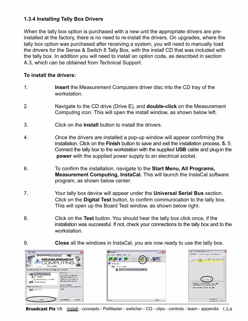
To install the drivers:
1. Insert the Measurement Computers driver disc into the CD tray of the workstation.
2. Navigate to the CD drive (Drive E), and double-click on the Measurement Computing icon. This will open the install window, as shown below left.
3. Click on the Install button to install the drivers.
4. Once the drivers are installed a pop-up window will appear confirming the installation. Click on the Finish button to save and exit the installation process. 5. 5. Connect the tally box to the workstation with the supplied USB cable and plug-in the power with the supplied power supply to an electrical socket.
6. To confirm the installation, navigate to the Start Menu, All Programs, Measurement Computing, InstaCal. This will launch the InstaCal software program, as shown below center.
7. Your tally box device will appear under the Universal Serial Bus section. Click on the Digital Test button, to confirm communication to the tally box. This will open up the Board Test window, as shown below right.
8. Click on the Test button. You should hear the tally box click once, if the installation was successful. If not, check your connections to the tally box and to the workstation.
9. Close all the windows in InstaCal, you are now ready to use the tally box.
install - concepts - PixMaster - switcher - CG - clips - controls - team - appendix Broadcast Pix V8 1.3.5
1.3.5 Installing Multiple Tally Boxes
A standard system usually uses one tally box, however multiple tally boxes may be installed on a Broadcast Pix system. Multiple tally boxes expands the number tally outputs as well the number of General Purpose Inputs and Outputs (GPIOs), which can be used with Fluent Macros. Installation is the same, as described in section 1.3.3, however each tally box must be assigned to a specific board number.
To assign multiple tally boxes:
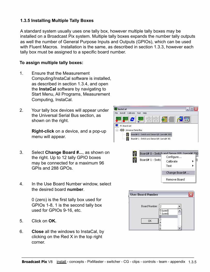
1. Ensure that the Measurement Computing/InstaCal software is installed, as described in section 1.3.4, and open the InstaCal software by navigating to Start Menu, All Programs, Measurement Computing, InstaCal.
2. Your tally box devices will appear under the Universal Serial Bus section, as shown on the right.
Right-click on a device, and a pop-up menu will appear.
3. Select Change Board #..., as shown on the right. Up to 12 tally GPIO boxes may be connected for a maximum 96 GPIs and 288 GPOs.
4. In the Use Board Number window, select the desired board number.
0 (zero) is the first tally box used for GPIOs 1-8, 1 is the second tally box used for GPIOs 9-16, etc.
5. Click on OK.
6. Close all the windows to InstaCal, by clicking on the Red X in the top right corner.
install - concepts - PixMaster - switcher - CG - clips - controls - team - appendix Broadcast Pix V8
1.4 Audio I/O
All Slate systems do not do any internal audio mixing, all mixing needs to be done externally. For automated control of external audio mixers, see section 7.14. One clip store is included on the Slate 100G and Slate 1000G. On a Slate 2100G and Slate 3000G two clip store channels are included. The clip store can be used with or without audio, and can either have embedded audio in/out through the Slate SD-SDI in/outputs or analog stereo audio through the 25 pin dim to XLR break out cable, which plugs into the back of the workstation. Both the inputs and the outputs of the breakout cable use a balanced line level signal.
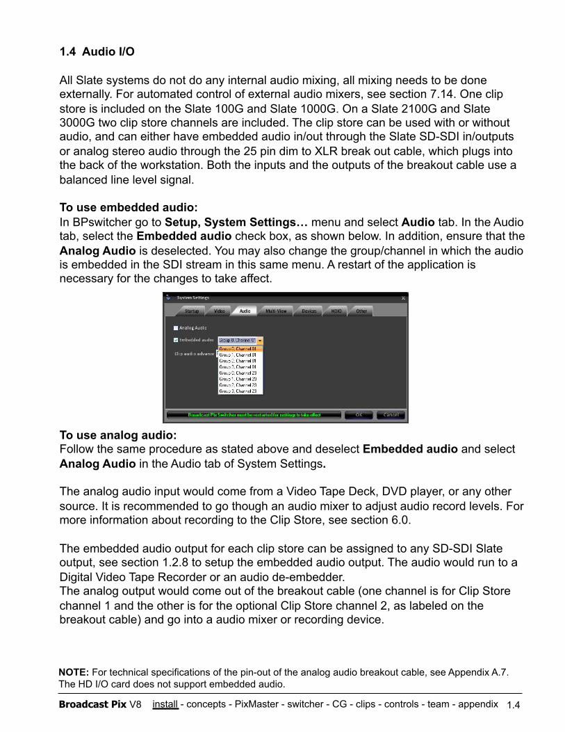
To use embedded audio: In BPswitcher go to Setup, System Settings… menu and select Audio tab. In the Audio tab, select the Embedded audio check box, as shown below. In addition, ensure that the Analog Audio is deselected. You may also change the group/channel in which the audio is embedded in the SDI stream in this same menu. A restart of the application is necessary for the changes to take affect.
To use analog audio: Follow the same procedure as stated above and deselect Embedded audio and select Analog Audio in the Audio tab of System Settings.
The analog audio input would come from a Video Tape Deck, DVD player, or any other source. It is recommended to go though an audio mixer to adjust audio record levels. For more information about recording to the Clip Store, see section 6.0.
The embedded audio output for each clip store can be assigned to any SD-SDI Slate output, see section 1.2.8 to setup the embedded audio output. The audio would run to a Digital Video Tape Recorder or an audio de-embedder. The analog output would come out of the breakout cable (one channel is for Clip Store channel 1 and the other is for the optional Clip Store channel 2, as labeled on the breakout cable) and go into a audio mixer or recording device.
1.4
NOTE: For technical specifications of the pin-out of the analog audio breakout cable, see Appendix A.7. The HD I/O card does not support embedded audio.
install - concepts - PixMaster - switcher - CG - clips - controls - team - appendix Broadcast Pix V8
To Assign the Slate I/O:
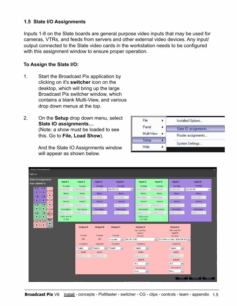
1. Start the Broadcast Pix application by clicking on it's switcher icon on the desktop, which will bring up the large Broadcast Pix switcher window, which contains a blank Multi-View, and various drop down menus at the top.
2. On the Setup drop down menu, select Slate IO assignments… (Note: a show must be loaded to see this. Go to File, Load Show).
And the Slate IO Assignments window will appear as shown below.
1.5 Slate I/O Assignments
Inputs 1-8 on the Slate boards are general purpose video inputs that may be used for cameras, VTRs, and feeds from servers and other external video devices. Any input/output connected to the Slate video cards in the workstation needs to be configured with this assignment window to ensure proper operation.
1.5
install - concepts - PixMaster - switcher - CG - clips - controls - team - appendix Broadcast Pix V8
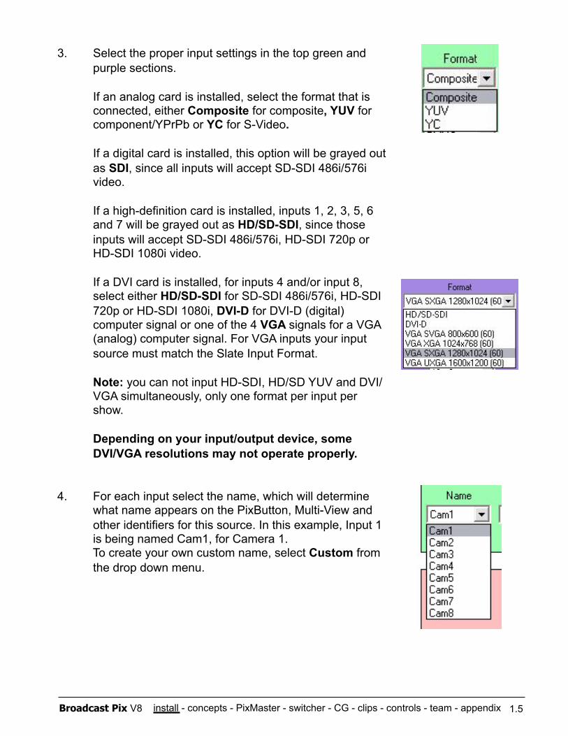
3. Select the proper input settings in the top green and purple sections.
If an analog card is installed, select the format that is connected, either Composite for composite, YUV for component/YPrPb or YC for S-Video.
If a digital card is installed, this option will be grayed out as SDI, since all inputs will accept SD-SDI 486i/576i video.
If a high-definition card is installed, inputs 1, 2, 3, 5, 6 and 7 will be grayed out as HD/SD-SDI, since those inputs will accept SD-SDI 486i/576i, HD-SDI 720p or HD-SDI 1080i video.
If a DVI card is installed, for inputs 4 and/or input 8, select either HD/SD-SDI for SD-SDI 486i/576i, HD-SDI 720p or HD-SDI 1080i, DVI-D for DVI-D (digital) computer signal or one of the 4 VGA signals for a VGA (analog) computer signal. For VGA inputs your input source must match the Slate Input Format.
Note: you can not input HD-SDI, HD/SD YUV and DVI/VGA simultaneously, only one format per input per show.
Depending on your input/output device, some DVI/VGA resolutions may not operate properly.
4. For each input select the name, which will determine what name appears on the PixButton, Multi-View and other identifiers for this source. In this example, Input 1 is being named Cam1, for Camera 1. To create your own custom name, select Custom from the drop down menu.
1.5
install - concepts - PixMaster - switcher - CG - clips - controls - team - appendix Broadcast Pix V8
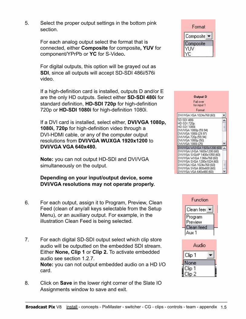
5. Select the proper output settings in the bottom pink section.
For each analog output select the format that is connected, either Composite for composite, YUV for component/YPrPb or YC for S-Video.
For digital outputs, this option will be grayed out as SDI, since all outputs will accept SD-SDI 486i/576i video.
If a high-definition card is installed, outputs D and/or E are the only HD outputs. Select either SD-SDI 480i for standard definition, HD-SDI 720p for high-definition 720p or HD-SDI 1080i for high-definition 1080i.
If a DVI card is installed, select either, DVI/VGA 1080p, 1080i, 720p for high-definition video through a DVI-HDMI cable, or any of the computer output resolutions from DVI/VGA WUXGA 1920x1200 to DVI/VGA VGA 640x480.
Note: you can not output HD-SDI and DVI/VGA simultaneously on the output.
Depending on your input/output device, some DVI/VGA resolutions may not operate properly.
6. For each output, assign it to Program, Preview, Clean Feed (clean of any/all keys selectable from the Setup Menu), or an auxiliary output. For example, in the illustration Clean Feed is being selected.
7. For each digital SD-SDI output select which clip store audio will be outputted on the embedded SDI stream. Either None, Clip 1 or Clip 2. To activate embedded audio see section 1.2.7. Note: you can not output embedded audio on a HD I/O card.
8. Click on Save in the lower right corner of the Slate IO Assignments window to save and exit.
1.5
install - concepts - PixMaster - switcher - CG - clips - controls - team - appendix Broadcast Pix V8 1.5.1
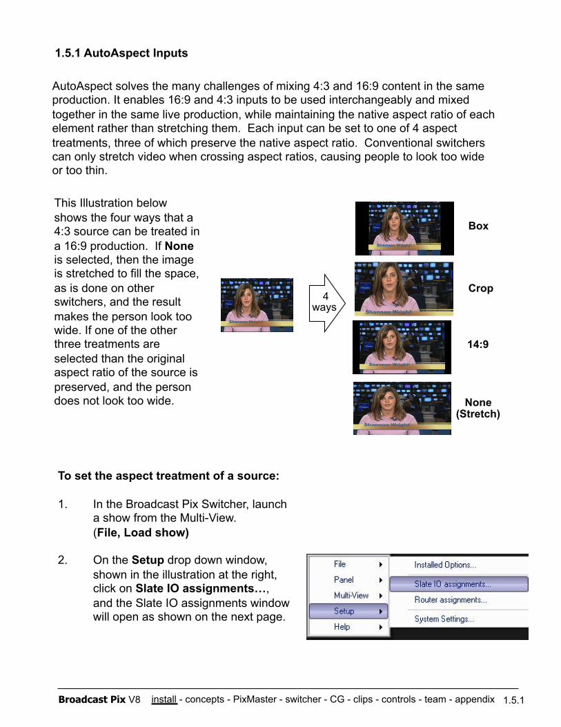
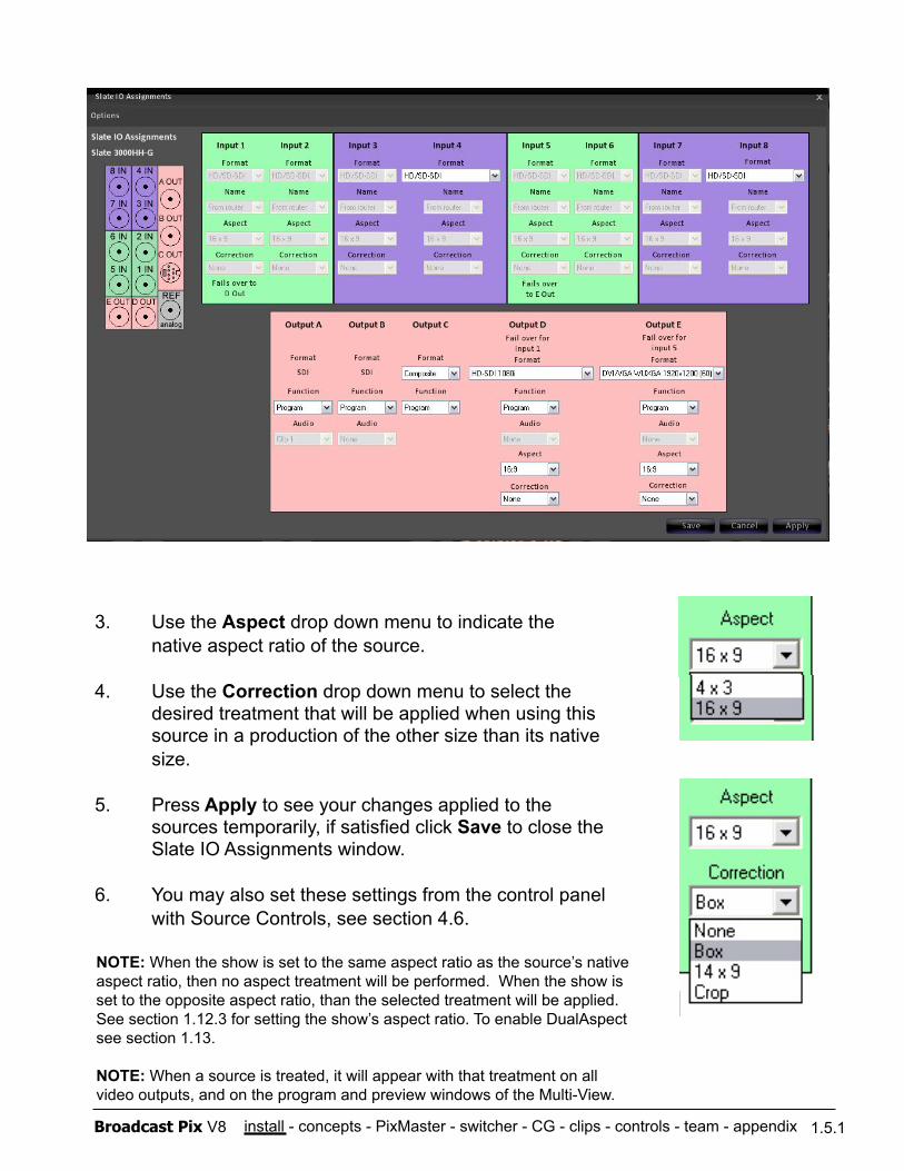
1.5.1 AutoAspect Inputs
None (Stretch)
14:9
4 ways
AutoAspect solves the many challenges of mixing 4:3 and 16:9 content in the same production. It enables 16:9 and 4:3 inputs to be used interchangeably and mixed together in the same live production, while maintaining the native aspect ratio of each element rather than stretching them. Each input can be set to one of 4 aspect treatments, three of which preserve the native aspect ratio. Conventional switchers can only stretch video when crossing aspect ratios, causing people to look too wide or too thin.
To set the aspect treatment of a source:
1. In the Broadcast Pix Switcher, launch a show from the Multi-View. (File, Load show)
2. On the Setup drop down window, shown in the illustration at the right, click on Slate IO assignments…, and the Slate IO assignments window will open as shown on the next page.
This Illustration below shows the four ways that a 4:3 source can be treated in a 16:9 production. If None is selected, then the image is stretched to fill the space, as is done on other switchers, and the result makes the person look too wide. If one of the other three treatments are selected than the original aspect ratio of the source is preserved, and the person does not look too wide.
Box
Crop
install - concepts - PixMaster - switcher - CG - clips - controls - team - appendix Broadcast Pix V8 1.5.1
3. Use the Aspect drop down menu to indicate the native aspect ratio of the source.
4. Use the Correction drop down menu to select the desired treatment that will be applied when using this source in a production of the other size than its native size.
5. Press Apply to see your changes applied to the sources temporarily, if satisfied click Save to close the Slate IO Assignments window.
6. You may also set these settings from the control panel with Source Controls, see section 4.6.
NOTE: When the show is set to the same aspect ratio as the source’s native aspect ratio, then no aspect treatment will be performed. When the show is set to the opposite aspect ratio, than the selected treatment will be applied. See section 1.12.3 for setting the show’s aspect ratio. To enable DualAspect see section 1.13.
NOTE: When a source is treated, it will appear with that treatment on all video outputs, and on the program and preview windows of the Multi-View.
install - concepts - PixMaster - switcher - CG - clips - controls - team - appendix Broadcast Pix V8
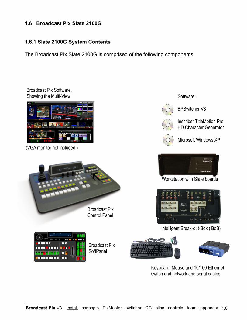
1.6 Broadcast Pix Slate 2100G
1.6.1 Slate 2100G System Contents
The Broadcast Pix Slate 2100G is comprised of the following components:
Broadcast Pix Control Panel
Workstation with Slate boards
Software:
BPSwitcher V8
Inscriber TitleMotion Pro HD Character Generator
Microsoft Windows XP
Broadcast Pix Software, Showing the Multi-View
Keyboard, Mouse and 10/100 Ethernet switch and network and serial cables
Intelligent Break-out-Box (iBoB)
Broadcast Pix SoftPanel
1.6
(VGA monitor not included )
install - concepts - PixMaster - switcher - CG - clips - controls - team - appendix Broadcast Pix V8
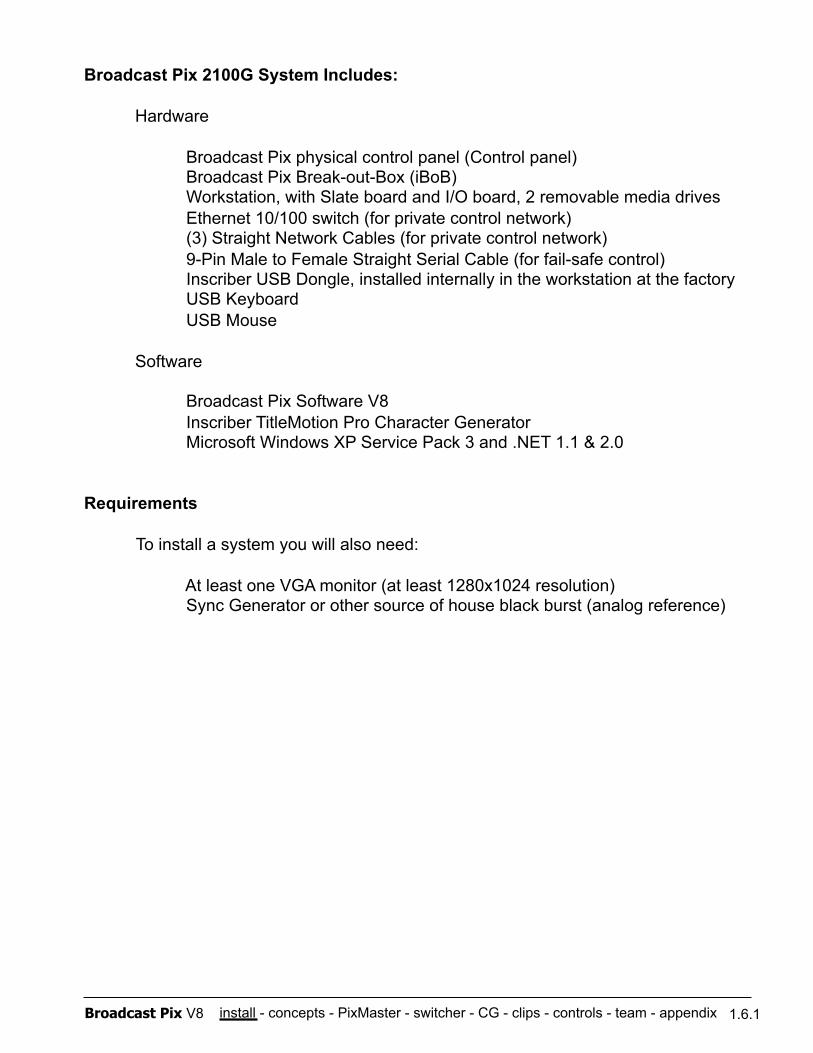
Broadcast Pix 2100G System Includes:
Hardware Broadcast Pix physical control panel (Control panel) Broadcast Pix Break-out-Box (iBoB) Workstation, with Slate board and I/O board, 2 removable media drives Ethernet 10/100 switch (for private control network) (3) Straight Network Cables (for private control network) 9-Pin Male to Female Straight Serial Cable (for fail-safe control) Inscriber USB Dongle, installed internally in the workstation at the factory USB Keyboard USB Mouse
Software
Broadcast Pix Software V8 Inscriber TitleMotion Pro Character Generator Microsoft Windows XP Service Pack 3 and .NET 1.1 & 2.0
Requirements
To install a system you will also need:
At least one VGA monitor (at least 1280x1024 resolution) Sync Generator or other source of house black burst (analog reference)
1.6.1
install - concepts - PixMaster - switcher - CG - clips - controls - team - appendix Broadcast Pix V8
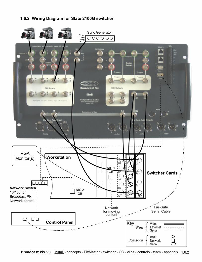
1.6.2 Wiring the Slate 2100G
1. Attach analog reference/blackburst. Run one wire from your sync generator to the Break-out-Box’s (iBoB) reference input, and then run a second wire from the iBoB’s reference output to the ‘Ref’ input on the Slate switcher card, as shown on the wiring diagram on the next page. You may use the other ‘Ref Outs’ to feed your cameras, tape machines or other sources that accept genlock.
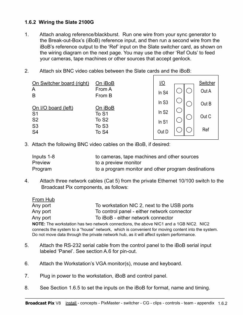
2. Attach six BNC video cables between the Slate cards and the iBoB:
On Switcher board (right) On iBoB A From A B From B
On I/O board (left) On iBoB S1 To S1 S2 To S2 S3 To S3 S4 To S4
3. Attach the following BNC video cables on the iBoB, if desired:
Inputs 1-8 to cameras, tape machines and other sources Preview to a preview monitor Program to a program monitor and other program destinations
4. Attach three network cables (Cat 5) from the private Ethernet 10/100 switch to the Broadcast Pix components, as follows:
From Hub Any port To workstation NIC 2, next to the USB ports Any port To control panel - either network connector Any port To iBoB - either network connector NOTE: The workstation has two network connections, the above NIC1 and a 1GB NIC2. NIC2 connects the system to a “house” network, which is convenient for moving content into the system. Do not move data through the private network hub, as it will affect system performance.
5. Attach the RS-232 serial cable from the control panel to the iBoB serial input labeled ‘Panel’. See section A.6 for pin-out.
6. Attach the Workstation’s VGA monitor(s), mouse and keyboard.
7. Plug in power to the workstation, iBoB and control panel.
8. See Section 1.6.5 to set the inputs on the iBoB for format, name and timing.
1.6.2
Out A
Out B
Out C
Ref
Switcher
In S4
In S3
In S2
In S1
Out D
I/O
install - concepts - PixMaster - switcher - CG - clips - controls - team - appendix Broadcast Pix V8
Network for moving
content
NIC 1 1GB
1.6.2 Wiring Diagram for Slate 2100G switcher
Workstation
Fail-Safe Serial Cable
1.6.2
Control Panel
Network Switch 10/100 for Broadcast Pix Network control
Switcher Cards
Video Ethernet Serial
BNC Network Serial
Wires
Connectors
Key
VGA Monitor(s)
NIC 2 1GB
Sync Generator
S8
S7
S6
S5
E
S4
S3
S2
S1
D
A
B
C
REF
install - concepts - PixMaster - switcher - CG - clips - controls - team - appendix Broadcast Pix V8 1.6.2
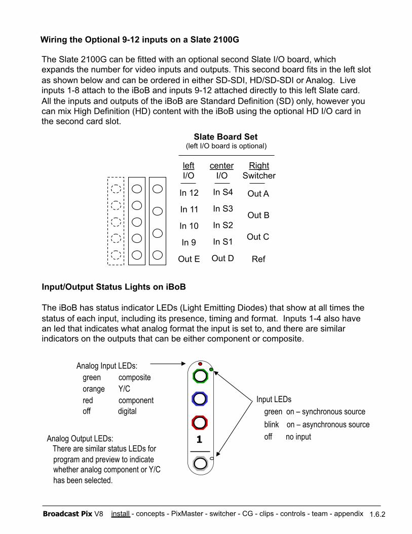
Input/Output Status Lights on iBoB
The iBoB has status indicator LEDs (Light Emitting Diodes) that show at all times the status of each input, including its presence, timing and format. Inputs 1-4 also have an led that indicates what analog format the input is set to, and there are similar indicators on the outputs that can be either component or composite.
Analog Input LEDs: green composite orange Y/C red component off digital
Input LEDs green on – synchronous source blink on – asynchronous source off no input Analog Output LEDs:
There are similar status LEDs for program and preview to indicate whether analog component or Y/C has been selected.
Wiring the Optional 9-12 inputs on a Slate 2100G
Out A
Out B
Out C
Ref
Right Switcher
In S4
In S3
In S2
In S1
Out D
center I/O
In 12
In 11
In 10
In 9
Out E
left I/O
Slate Board Set (left I/O board is optional)
The Slate 2100G can be fitted with an optional second Slate I/O board, which expands the number for video inputs and outputs. This second board fits in the left slot as shown below and can be ordered in either SD-SDI, HD/SD-SDI or Analog. Live inputs 1-8 attach to the iBoB and inputs 9-12 attached directly to this left Slate card. All the inputs and outputs of the iBoB are Standard Definition (SD) only, however you can mix High Definition (HD) content with the iBoB using the optional HD I/O card in the second card slot.
1
install - concepts - PixMaster - switcher - CG - clips - controls - team - appendix Broadcast Pix V8 1.6.3
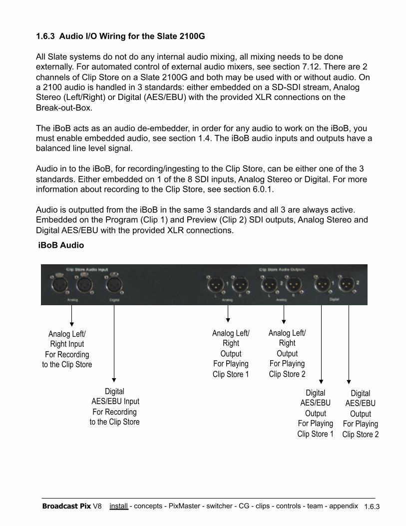
1.6.3 Audio I/O Wiring for the Slate 2100G
All Slate systems do not do any internal audio mixing, all mixing needs to be done externally. For automated control of external audio mixers, see section 7.12. There are 2 channels of Clip Store on a Slate 2100G and both may be used with or without audio. On a 2100 audio is handled in 3 standards: either embedded on a SD-SDI stream, Analog Stereo (Left/Right) or Digital (AES/EBU) with the provided XLR connections on the Break-out-Box.
The iBoB acts as an audio de-embedder, in order for any audio to work on the iBoB, you must enable embedded audio, see section 1.4. The iBoB audio inputs and outputs have a balanced line level signal.
Audio in to the iBoB, for recording/ingesting to the Clip Store, can be either one of the 3 standards. Either embedded on 1 of the 8 SDI inputs, Analog Stereo or Digital. For more information about recording to the Clip Store, see section 6.0.1.
Audio is outputted from the iBoB in the same 3 standards and all 3 are always active. Embedded on the Program (Clip 1) and Preview (Clip 2) SDI outputs, Analog Stereo and Digital AES/EBU with the provided XLR connections.
iBoB Audio
Analog Left/Right Input
For Recording to the Clip Store
Analog Left/Right
Output For Playing Clip Store 1
Analog Left/Right
Output For Playing Clip Store 2
Digital AES/EBU Input For Recording
to the Clip Store
Digital AES/EBU
Output For Playing Clip Store 1
Digital AES/EBU
Output For Playing Clip Store 2
install - concepts - PixMaster - switcher - CG - clips - controls - team - appendix Broadcast Pix V8 1.6.4
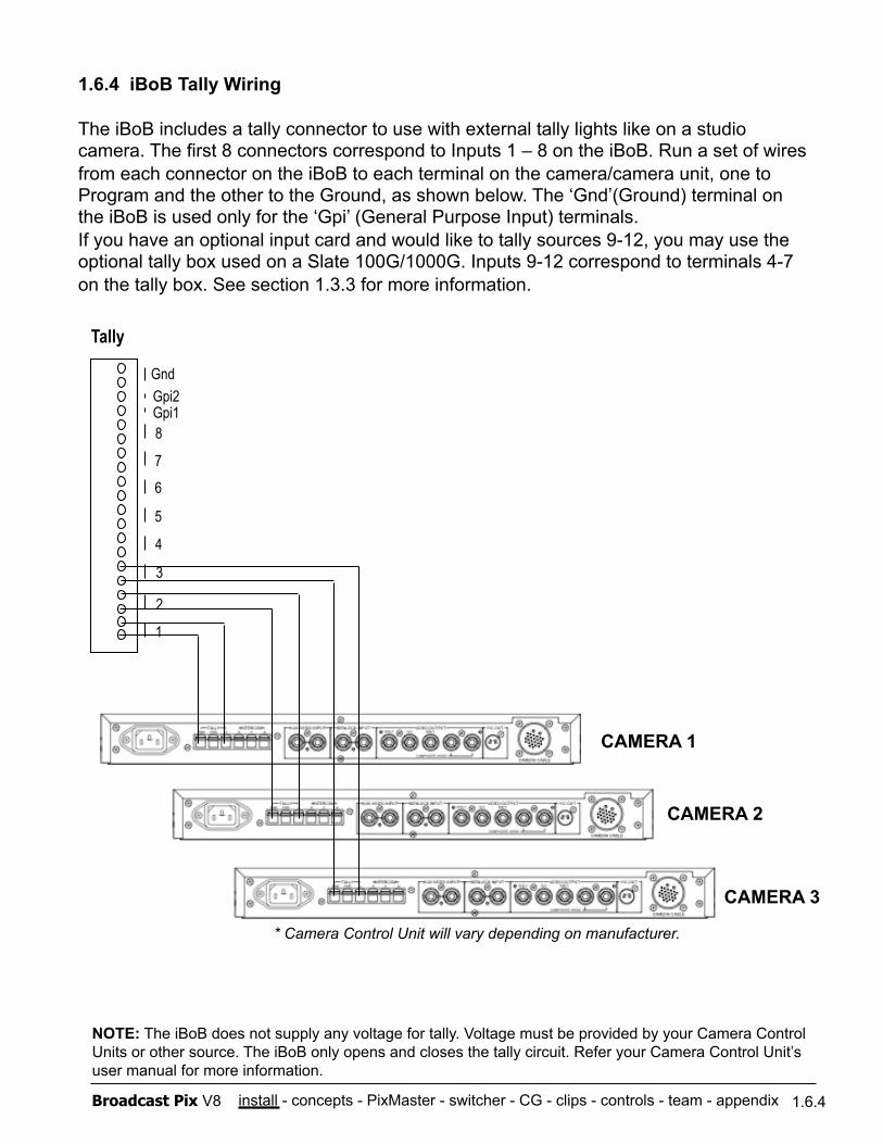
NOTE: The iBoB does not supply any voltage for tally. Voltage must be provided by your Camera Control Units or other source. The iBoB only opens and closes the tally circuit. Refer your Camera Control Unit’s user manual for more information.
1.6.4 iBoB Tally Wiring
The iBoB includes a tally connector to use with external tally lights like on a studio camera. The first 8 connectors correspond to Inputs 1 – 8 on the iBoB. Run a set of wires from each connector on the iBoB to each terminal on the camera/camera unit, one to Program and the other to the Ground, as shown below. The ‘Gnd’(Ground) terminal on the iBoB is used only for the ‘Gpi’ (General Purpose Input) terminals. If you have an optional input card and would like to tally sources 9-12, you may use the optional tally box used on a Slate 100G/1000G. Inputs 9-12 correspond to terminals 4-7 on the tally box. See section 1.3.3 for more information.
Tally
1
Gnd
Gpi1 Gpi2
8
7
6
5
4
3
2
* Camera Control Unit will vary depending on manufacturer.
CAMERA 1
CAMERA 2
CAMERA 3
install - concepts - PixMaster - switcher - CG - clips - controls - team - appendix Broadcast Pix V8
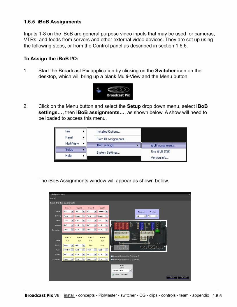
To Assign the iBoB I/O:
1. Start the Broadcast Pix application by clicking on the Switcher icon on the desktop, which will bring up a blank Multi-View and the Menu button.
2. Click on the Menu button and select the Setup drop down menu, select iBoB settings…, then iBoB assignments…, as shown below. A show will need to be loaded to access this menu.
The iBoB Assignments window will appear as shown below.
1.6.5 iBoB Assignments
Inputs 1-8 on the iBoB are general purpose video inputs that may be used for cameras, VTRs, and feeds from servers and other external video devices. They are set up using the following steps, or from the Control panel as described in section 1.6.6.
1.6.5
install - concepts - PixMaster - switcher - CG - clips - controls - team - appendix Broadcast Pix V8
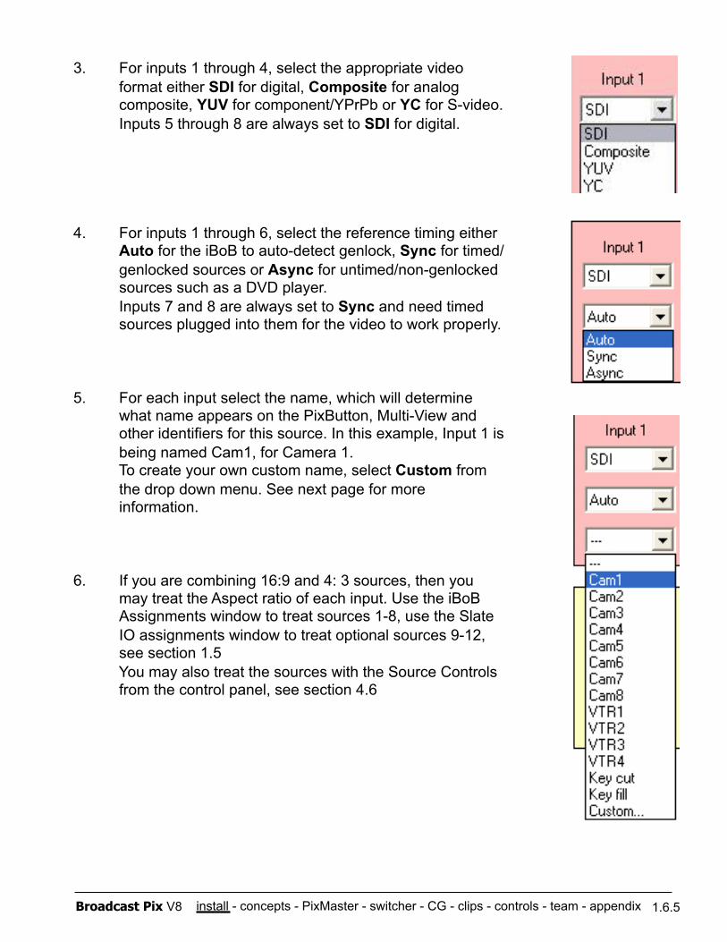
3. For inputs 1 through 4, select the appropriate video format either SDI for digital, Composite for analog composite, YUV for component/YPrPb or YC for S-video. Inputs 5 through 8 are always set to SDI for digital.
4. For inputs 1 through 6, select the reference timing either Auto for the iBoB to auto-detect genlock, Sync for timed/genlocked sources or Async for untimed/non-genlocked sources such as a DVD player. Inputs 7 and 8 are always set to Sync and need timed sources plugged into them for the video to work properly.
5. For each input select the name, which will determine what name appears on the PixButton, Multi-View and other identifiers for this source. In this example, Input 1 is being named Cam1, for Camera 1. To create your own custom name, select Custom from the drop down menu. See next page for more information.
6. If you are combining 16:9 and 4: 3 sources, then you may treat the Aspect ratio of each input. Use the iBoB Assignments window to treat sources 1-8, use the Slate IO assignments window to treat optional sources 9-12, see section 1.5 You may also treat the sources with the Source Controls from the control panel, see section 4.6
1.6.5
install - concepts - PixMaster - switcher - CG - clips - controls - team - appendix Broadcast Pix V8
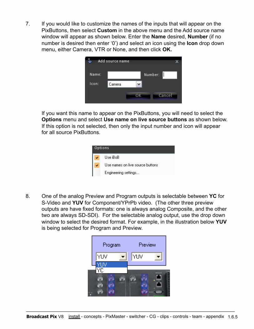
7. If you would like to customize the names of the inputs that will appear on the PixButtons, then select Custom in the above menu and the Add source name window will appear as shown below. Enter the Name desired, Number (if no number is desired then enter ‘0’) and select an icon using the Icon drop down menu, either Camera, VTR or None, and then click OK.
If you want this name to appear on the PixButtons, you will need to select the Options menu and select Use name on live source buttons as shown below. If this option is not selected, then only the input number and icon will appear for all source PixButtons.
8. One of the analog Preview and Program outputs is selectable between YC for S-Video and YUV for Component/YPrPb video. (The other three preview outputs are have fixed formats: one is always analog Composite, and the other two are always SD-SDI). For the selectable analog output, use the drop down window to select the desired format. For example, in the illustration below YUV is being selected for Program and Preview.
1.6.5
install - concepts - PixMaster - switcher - CG - clips - controls - team - appendix Broadcast Pix V8 1.6.5
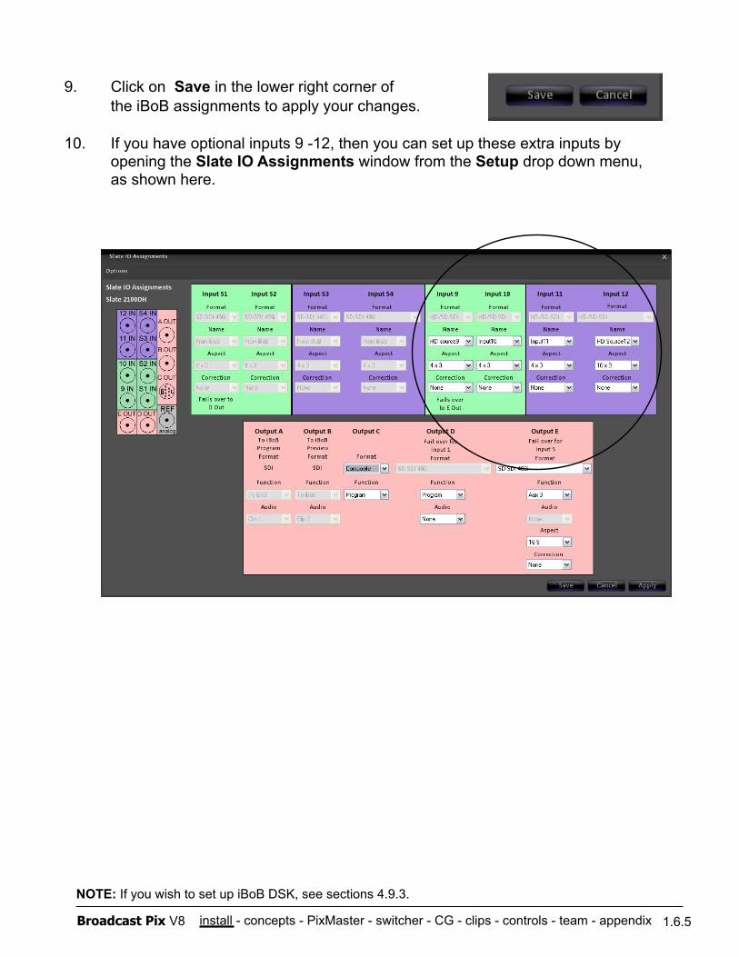
9. Click on Save in the lower right corner of the iBoB assignments to apply your changes.
10. If you have optional inputs 9 -12, then you can set up these extra inputs by opening the Slate IO Assignments window from the Setup drop down menu, as shown here.
NOTE: If you wish to set up iBoB DSK, see sections 4.9.3.
install - concepts - PixMaster - switcher - CG - clips - controls - team - appendix Broadcast Pix V8 1.6.6
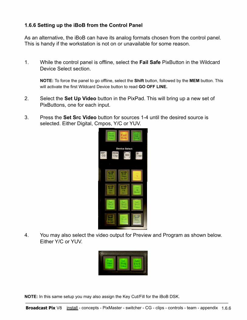
1.6.6 Setting up the iBoB from the Control Panel
As an alternative, the iBoB can have its analog formats chosen from the control panel. This is handy if the workstation is not on or unavailable for some reason.
1. While the control panel is offline, select the Fail Safe PixButton in the Wildcard Device Select section.
NOTE: To force the panel to go offline, select the Shift button, followed by the MEM button. This will activate the first Wildcard Device button to read GO OFF LINE.
2. Select the Set Up Video button in the PixPad. This will bring up a new set of PixButtons, one for each input.
3. Press the Set Src Video button for sources 1-4 until the desired source is selected. Either Digital, Cmpos, Y/C or YUV.
4. You may also select the video output for Preview and Program as shown below. Either Y/C or YUV.
NOTE: In this same setup you may also assign the Key Cut/Fill for the iBoB DSK.
install - concepts - PixMaster - switcher - CG - clips - controls - team - appendix Broadcast Pix V8
1.7 Broadcast Pix Slate 3000G
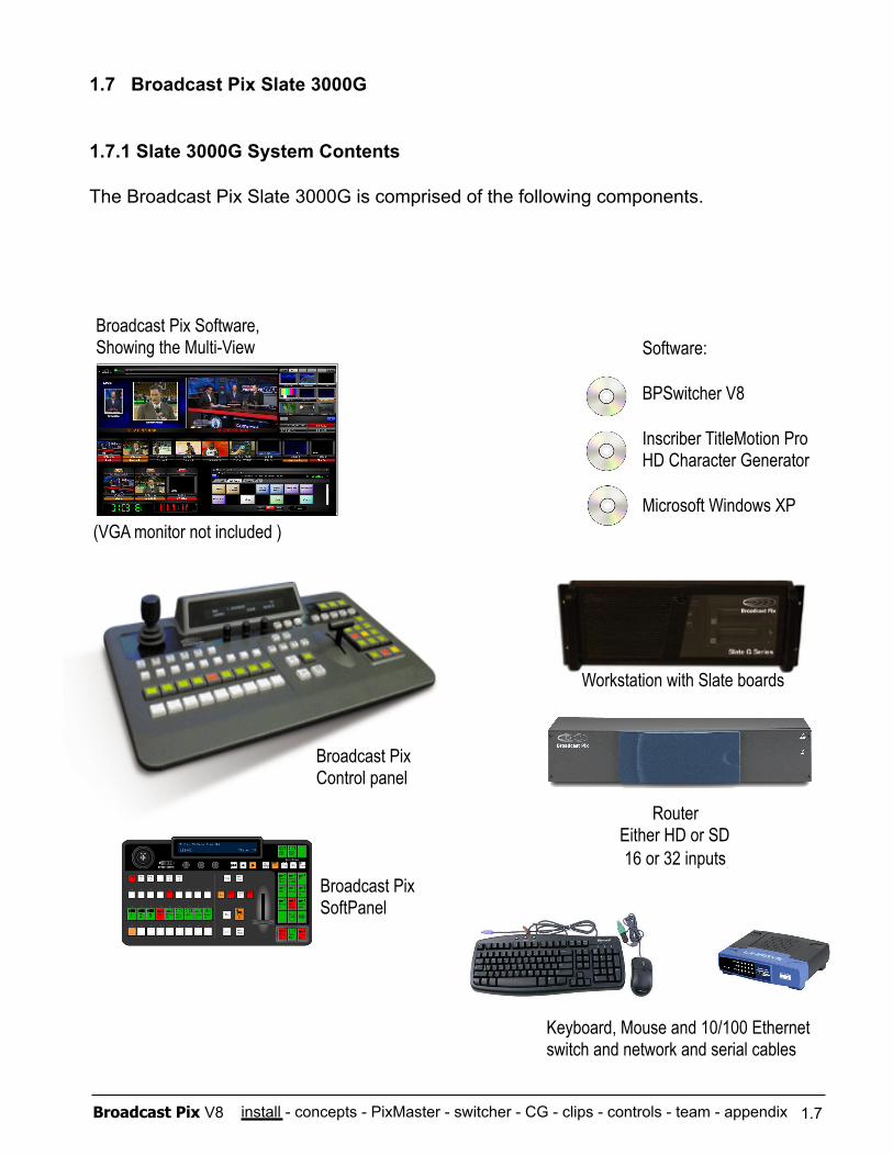
1.7.1 Slate 3000G System Contents
The Broadcast Pix Slate 3000G is comprised of the following components.
Broadcast Pix Control panel
Workstation with Slate boards
Software:
BPSwitcher V8
Inscriber TitleMotion Pro HD Character Generator
Microsoft Windows XP
Broadcast Pix Software, Showing the Multi-View
Keyboard, Mouse and 10/100 Ethernet switch and network and serial cables
Router Either HD or SD 16 or 32 inputs
Broadcast Pix SoftPanel
1.7
(VGA monitor not included )
install - concepts - PixMaster - switcher - CG - clips - controls - team - appendix Broadcast Pix V8
Broadcast Pix 3000G System Includes:
Hardware Broadcast Pix physical control panel (Control Panel) 16x16 or 32x32 Broadcast Pix Router (HD or SD) Workstation, with Slate board and I/O board, 2 removable media drives Ethernet 10/100 Switch (for private control network) (3) Straight Network Cables (for private control network) 9-Pin Male to Female Straight Serial Cable (for fail-safe control) 25-Pin to 6-XLR Audio Breakout Cable (for analog audio I/O) Inscriber USB Dongle, installed internally in the workstation at the factory USB Keyboard USB Mouse
Software
Broadcast Pix Software V8 Inscriber TitleMotion Pro Character Generator Microsoft Windows XP Service Pack 3 and .NET 1.1 & 2.0
Requirements
To install a system you will also need:
At least one VGA monitor (at least 1280x1024 resolution) Sync Generator or other source of house black burst (analog reference)
1.7.1
install - concepts - PixMaster - switcher - CG - clips - controls - team - appendix Broadcast Pix V8
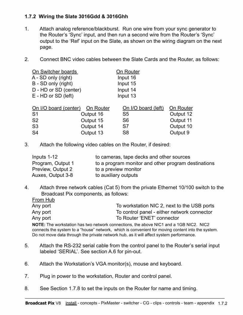
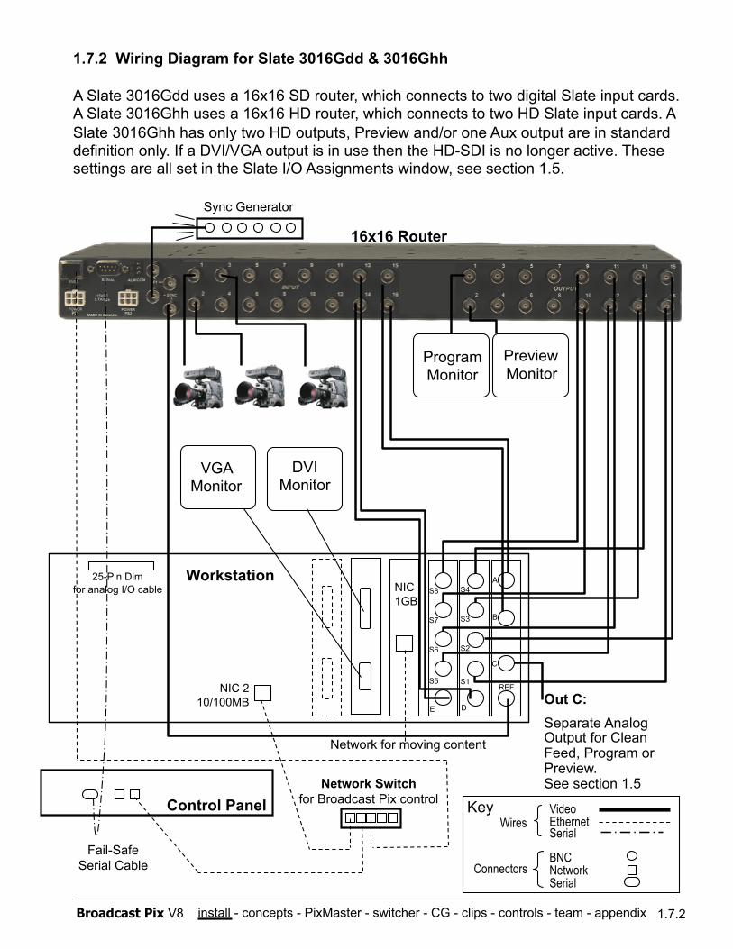
1.7.2 Wiring the Slate 3016Gdd & 3016Ghh
1. Attach analog reference/blackburst. Run one wire from your sync generator to the Router’s ‘Sync’ input, and then run a second wire from the Router’s ‘Sync’ output to the ‘Ref’ input on the Slate, as shown on the wiring diagram on the next page.
2. Connect BNC video cables between the Slate Cards and the Router, as follows:
On Switcher boards On Router A - SD only (right) Input 16 B - SD only (right) Input 15 D - HD or SD (center) Input 14 E - HD or SD (left) Input 13
On I/O board (center) On Router S1 Output 16 S2 Output 15 S3 Output 14 S4 Output 13
3. Attach the following video cables on the Router, if desired:
Inputs 1-12 to cameras, tape decks and other sources Program, Output 1 to a program monitor and other program destinations Preview, Output 2 to a preview monitor Auxes, Output 3-8 to auxiliary outputs
4. Attach three network cables (Cat 5) from the private Ethernet 10/100 switch to the Broadcast Pix components, as follows: From Hub Any port To workstation NIC 2, next to the USB ports Any port To control panel - either network connector Any port To Router ‘ENET’ connector NOTE: The workstation has two network connections, the above NIC1 and a 1GB NIC2. NIC2 connects the system to a “house” network, which is convenient for moving content into the system. Do not move data through the private network hub, as it will affect system performance.
5. Attach the RS-232 serial cable from the control panel to the Router’s serial input labeled ‘SERIAL’. See section A.6 for pin-out.
6. Attach the Workstation’s VGA monitor(s), mouse and keyboard.
7. Plug in power to the workstation, Router and control panel.
8. See Section 1.7.8 to set the inputs on the Router for name and timing.
1.7.2
On I/O board (left) On Router S5 Output 12 S6 Output 11 S7 Output 10 S8 Output 9
install - concepts - PixMaster - switcher - CG - clips - controls - team - appendix Broadcast Pix V8
1.7.2 Wiring Diagram for Slate 3016Gdd & 3016Ghh
A Slate 3016Gdd uses a 16x16 SD router, which connects to two digital Slate input cards. A Slate 3016Ghh uses a 16x16 HD router, which connects to two HD Slate input cards. A Slate 3016Ghh has only two HD outputs, Preview and/or one Aux output are in standard definition only. If a DVI/VGA output is in use then the HD-SDI is no longer active. These settings are all set in the Slate I/O Assignments window, see section 1.5.
Workstation
Sync Generator
Fail-Safe Serial Cable
1.7.2
16x16 Router
Control Panel Network Switch
for Broadcast Pix control Video Ethernet Serial
BNC Network Serial
Wires
Connectors
Key
VGA Monitor
Network for moving content
NIC 1GB
Preview Monitor
DVI Monitor
Program Monitor
NIC 2 10/100MB Out C:
Separate Analog Output for Clean Feed, Program or Preview. See section 1.5
S8
S7
S6
S5
E
S4
S3
S2
S1
D
A
B
C
REF
25-Pin Dim for analog I/O cable
install - concepts - PixMaster - switcher - CG - clips - controls - team - appendix Broadcast Pix V8
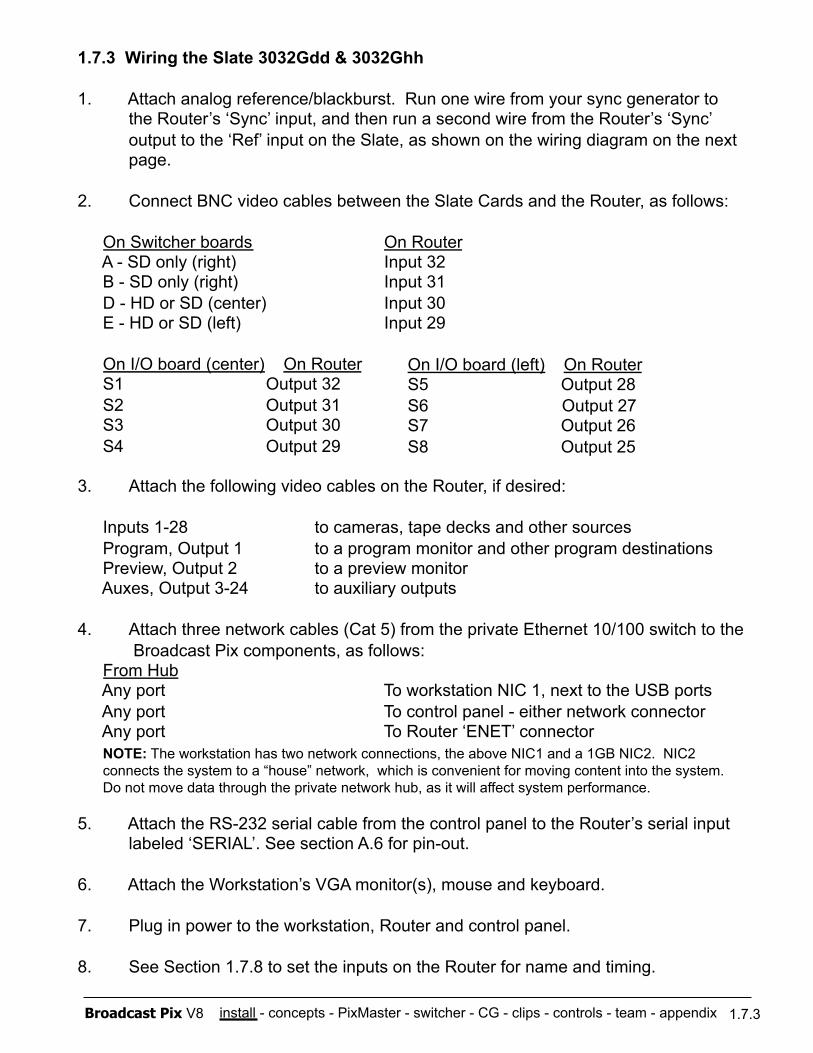
1.7.3 Wiring the Slate 3032Gdd & 3032Ghh
1. Attach analog reference/blackburst. Run one wire from your sync generator to the Router’s ‘Sync’ input, and then run a second wire from the Router’s ‘Sync’ output to the ‘Ref’ input on the Slate, as shown on the wiring diagram on the next page.
2. Connect BNC video cables between the Slate Cards and the Router, as follows:
On Switcher boards On Router A - SD only (right) Input 32 B - SD only (right) Input 31 D - HD or SD (center) Input 30 E - HD or SD (left) Input 29
On I/O board (center) On Router S1 Output 32 S2 Output 31 S3 Output 30 S4 Output 29
3. Attach the following video cables on the Router, if desired:
Inputs 1-28 to cameras, tape decks and other sources Program, Output 1 to a program monitor and other program destinations Preview, Output 2 to a preview monitor Auxes, Output 3-24 to auxiliary outputs
4. Attach three network cables (Cat 5) from the private Ethernet 10/100 switch to the Broadcast Pix components, as follows: From Hub Any port To workstation NIC 1, next to the USB ports Any port To control panel - either network connector Any port To Router ‘ENET’ connector NOTE: The workstation has two network connections, the above NIC1 and a 1GB NIC2. NIC2 connects the system to a “house” network, which is convenient for moving content into the system. Do not move data through the private network hub, as it will affect system performance.
5. Attach the RS-232 serial cable from the control panel to the Router’s serial input labeled ‘SERIAL’. See section A.6 for pin-out.
6. Attach the Workstation’s VGA monitor(s), mouse and keyboard.
7. Plug in power to the workstation, Router and control panel.
8. See Section 1.7.8 to set the inputs on the Router for name and timing.
1.7.3
On I/O board (left) On Router S5 Output 28 S6 Output 27 S7 Output 26 S8 Output 25
install - concepts - PixMaster - switcher - CG - clips - controls - team - appendix Broadcast Pix V8
1.7.3 Wiring Diagram for Slate 3032Gdd & 3032Ghh
A Slate 3032Gdd uses a 32x32 SD router, which connects to two digital Slate input cards. A Slate 3032Ghh uses a 32x32 HD router, which connects to two HD Slate input cards. A Slate 3032Ghh has only two HD outputs, Preview and/or one Aux output are in standard definition only. If a DVI/VGA output is in use then the HD-SDI is no longer active. These settings are all set in the Slate I/O Assignments window, see section 1.5.
Workstation
Sync Generator
Fail-Safe Serial Cable
1.7.3
32x32 Router
Control Panel Network Switch
for Broadcast Pix control Video Ethernet Serial
BNC Network Serial
Wires
Connectors
Key
VGA Monitor
Network for moving content
NIC 1GB
DVI Monitor
NIC 2 10/100MB Out C:
Separate Analog Output for Clean Feed, Program or Preview. See section 1.5
Preview Monitor
Program Monitor
S8
S7
S6
S5
E
S4
S3
S2
S1
D
A
B
C
REF
25-Pin Dim for analog I/O cable
install - concepts - PixMaster - switcher - CG - clips - controls - team - appendix Broadcast Pix V8
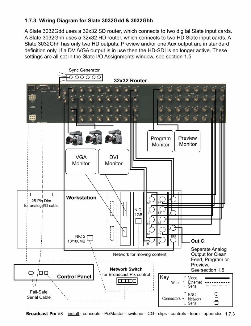
1.7.4 Optional Multi-System Control Wiring
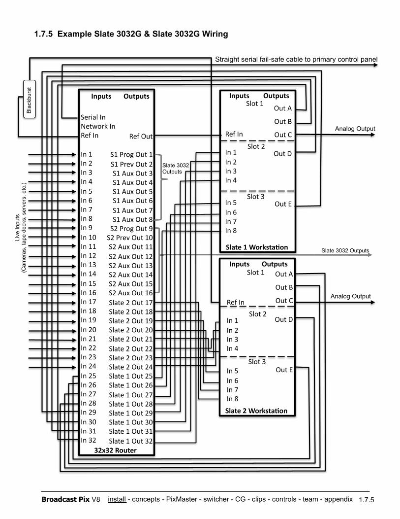
Unique to the Broadcast Pix Slate 3032G is the option to hook two or more Slate systems to one centralized router to share inputs and outputs. Great for larger facilities where multiple studios/control points are needed, it simplifies wiring by having one access point for all connections and lowers overall cost. Instead of purchasing two or three separate units, purchase one large system and increase your productivity.
There are several configurations where multiple Slates would useful and cost effective. The first is a low cost (without lacking any features) Studio B where you have a complete separate system to feed a different program, with access to Studio A sources if they are ever needed. This wiring method is good for multi-cast. Studios are often required to output one production to multiple mediums, such as broadcast, in-house IMAG (image magnification), web-cast, mobile, closed-circuit TV, etc. Although the content is virtually the same, the final output needs to be different. For example, web-casts are typically smaller in size/resolution so compositions need to be less complex, and they are also less forgiving when it comes to fast motion and smaller fonts. The studio diagram below shows a Slate 3032G controlling a broadcast output and another Slate 3032G controlling a less complex web-cast.
Connect two 1 M/E control panels or have a combination with a 1 M/E and a 2 M/E control panel from the Slate 5000G (or use a custom keyboard from a Slate 100G). There are a total of 24 external live inputs that are either independent or shared across both systems, and 8 outputs for each system (Preview/Program & Auxes). Both control panels, workstations and router connect to the same 100BASE-TX network switch, using a total of 5 ports. Fail-safe switching, however, can only be dedicated to one system, as the secondary system will have only 1 input outputted for fail-safe. See diagram on next page.
It is important to have unique IP addresses for each system, otherwise a network conflict will occur. Each system is configured from the factory to assure proper connectivity.
As there are many ways to connect multiple Slate systems, including with larger routers, it is advised to contact a Broadcast Pix representative for more information.
1.7.4
TV
Common Inputs Cameras and other external sources
Slate 3032G: 192.168.53.251 Slate 3032G: 192.168.53.241
Broadcast Pix 32x32 Router: 192.168.53.150
Workstation B: 192.168.53.240
Workstation A: 192.168.53.250
WEB
install - concepts - PixMaster - switcher - CG - clips - controls - team - appendix Broadcast Pix V8
Slate 1 Worksta1on
Slot 1
Ref In
In 1 In 2 In 3 In 4
In 5 In 6 In 7 In 8
Out A
Out B
Out C
Out D
Out E
Slot 2
Slot 3
Analog Output
Serial In Network In Ref In
In 1 In 2 In 3 In 4 In 5 In 6 In 7 In 8 In 9 In 10 In 11 In 12 In 13 In 14 In 15 In 16 In 17 In 18 In 19 In 20 In 21 In 22 In 23 In 24 In 25 In 26 In 27 In 28 In 29 In 30 In 31 In 32
Ref Out
S1 Prog Out 1 S1 Prev Out 2 S1 Aux Out 3 S1 Aux Out 4 S1 Aux Out 5 S1 Aux Out 6 S1 Aux Out 7 S1 Aux Out 8 S2 Prog Out 9 S2 Prev Out 10 S2 Aux Out 11 S2 Aux Out 12 S2 Aux Out 13 S2 Aux Out 14 S2 Aux Out 15 S2 Aux Out 16 Slate 2 Out 17 Slate 2 Out 18 Slate 2 Out 19 Slate 2 Out 20 Slate 2 Out 21 Slate 2 Out 22 Slate 2 Out 23 Slate 2 Out 24 Slate 1 Out 25 Slate 1 Out 26 Slate 1 Out 27 Slate 1 Out 28 Slate 1 Out 29 Slate 1 Out 30 Slate 1 Out 31 Slate 1 Out 32
32x32 Router
Straight serial fail-safe cable to primary control panel
Live
Inpu
ts
(Cam
eras
, tap
e de
cks,
ser
vers
, etc
.) B
lack
burs
t
Inputs Outputs Inputs Outputs
Ref In
In 1 In 2 In 3 In 4
In 5 In 6 In 7 In 8
Out A
Out B
Out C
Out D
Out E
Slot 2
Inputs Outputs Slot 1
Slate 2 Worksta1on
Slot 3
Analog Output
Slate 3032 Outputs
Slate 3032 Outputs
1.7.5 Example Slate 3032G & Slate 3032G Wiring
1.7.5
install - concepts - PixMaster - switcher - CG - clips - controls - team - appendix Broadcast Pix V8
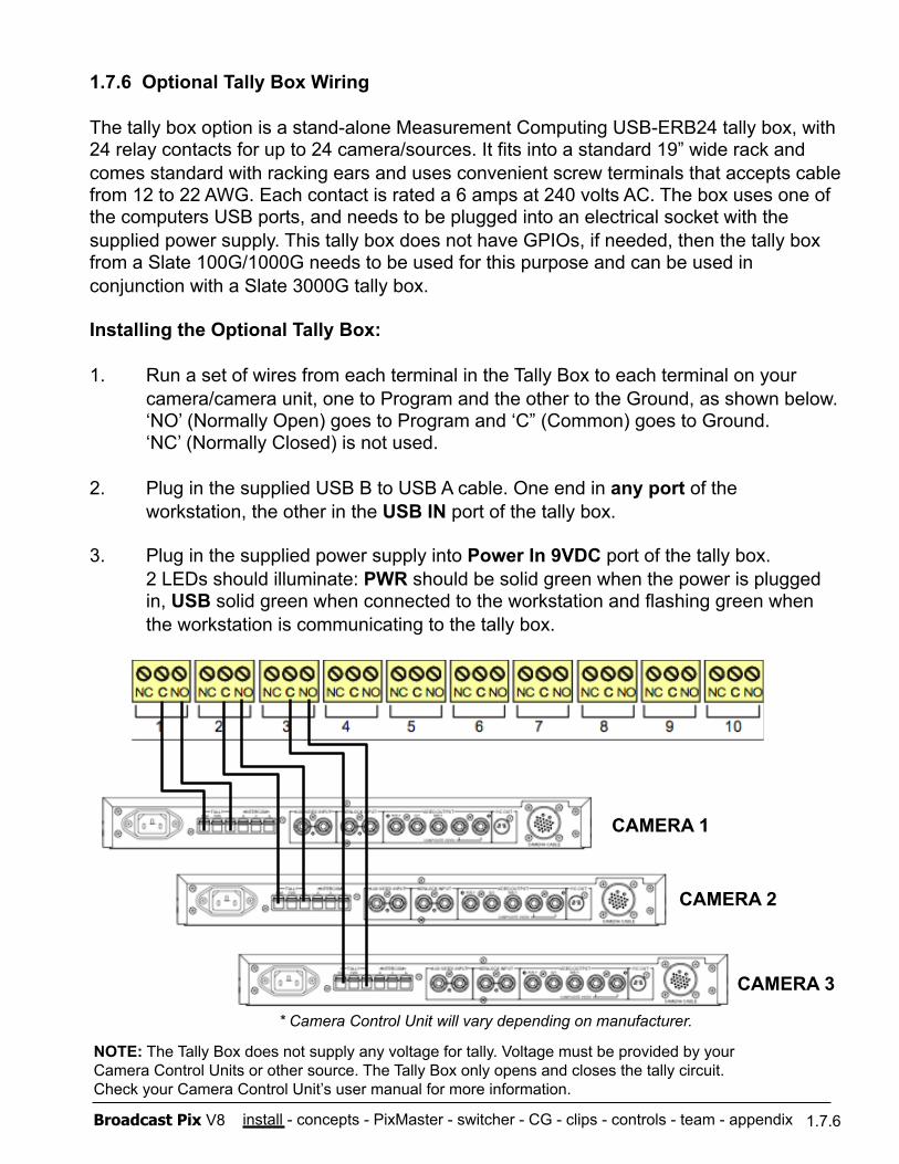
1.7.6 Optional Tally Box Wiring
The tally box option is a stand-alone Measurement Computing USB-ERB24 tally box, with 24 relay contacts for up to 24 camera/sources. It fits into a standard 19” wide rack and comes standard with racking ears and uses convenient screw terminals that accepts cable from 12 to 22 AWG. Each contact is rated a 6 amps at 240 volts AC. The box uses one of the computers USB ports, and needs to be plugged into an electrical socket with the supplied power supply. This tally box does not have GPIOs, if needed, then the tally box from a Slate 100G/1000G needs to be used for this purpose and can be used in conjunction with a Slate 3000G tally box.
Installing the Optional Tally Box:
1. Run a set of wires from each terminal in the Tally Box to each terminal on your camera/camera unit, one to Program and the other to the Ground, as shown below. ‘NO’ (Normally Open) goes to Program and ‘C” (Common) goes to Ground. ‘NC’ (Normally Closed) is not used.
2. Plug in the supplied USB B to USB A cable. One end in any port of the workstation, the other in the USB IN port of the tally box.
3. Plug in the supplied power supply into Power In 9VDC port of the tally box. 2 LEDs should illuminate: PWR should be solid green when the power is plugged in, USB solid green when connected to the workstation and flashing green when the workstation is communicating to the tally box.
1.7.6
NOTE: The Tally Box does not supply any voltage for tally. Voltage must be provided by your Camera Control Units or other source. The Tally Box only opens and closes the tally circuit. Check your Camera Control Unit’s user manual for more information.
* Camera Control Unit will vary depending on manufacturer.
CAMERA 1
CAMERA 2
CAMERA 3
install - concepts - PixMaster - switcher - CG - clips - controls - team - appendix Broadcast Pix V8
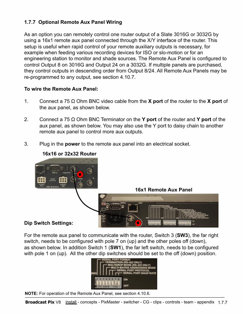
1.7.7 Optional Remote Aux Panel Wiring
As an option you can remotely control one router output of a Slate 3016G or 3032G by using a 16x1 remote aux panel connected through the X/Y interface of the router. This setup is useful when rapid control of your remote auxiliary outputs is necessary, for example when feeding various recording devices for ISO or slo-motion or for an engineering station to monitor and shade sources. The Remote Aux Panel is configured to control Output 8 on 3016G and Output 24 on a 3032G. If multiple panels are purchased, they control outputs in descending order from Output 8/24. All Remote Aux Panels may be re-programmed to any output, see section 4.10.7.
To wire the Remote Aux Panel:
1. Connect a 75 Ω Ohm BNC video cable from the X port of the router to the X port of the aux panel, as shown below.
2. Connect a 75 Ω Ohm BNC Terminator on the Y port of the router and Y port of the aux panel, as shown below. You may also use the Y port to daisy chain to another remote aux panel to control more aux outputs.
3. Plug in the power to the remote aux panel into an electrical socket.
Dip Switch Settings:
For the remote aux panel to communicate with the router, Switch 3 (SW3), the far right switch, needs to be configured with pole 7 on (up) and the other poles off (down), as shown below. In addition Switch 1 (SW1), the far left switch, needs to be configured with pole 1 on (up). All the other dip switches should be set to the off (down) position.
1.7.7
16x16 or 32x32 Router
16x1 Remote Aux Panel
NOTE: For operation of the Remote Aux Panel, see section 4.10.6.
install - concepts - PixMaster - switcher - CG - clips - controls - team - appendix Broadcast Pix V8
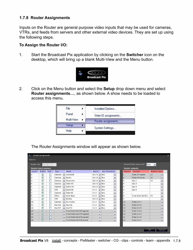
To Assign the Router I/O:
1. Start the Broadcast Pix application by clicking on the Switcher icon on the desktop, which will bring up a blank Multi-View and the Menu button.
2. Click on the Menu button and select the Setup drop down menu and select Router assignments…, as shown below. A show needs to be loaded to access this menu.
The Router Assignments window will appear as shown below.
1.7.8 Router Assignments
Inputs on the Router are general purpose video inputs that may be used for cameras, VTRs, and feeds from servers and other external video devices. They are set up using the following steps.
1.7.8
install - concepts - PixMaster - switcher - CG - clips - controls - team - appendix Broadcast Pix V8 1.7.8
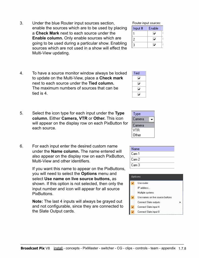
3. Under the blue Router input sources section, enable the sources which are to be used by placing a Check Mark next to each source under the Enable column. Only enable sources which are going to be used during a particular show. Enabling sources which are not used in a show will effect the Multi-View updating.
4. To have a source monitor window always be locked to update on the Multi-View, place a Check mark next to each source under the Tied column. The maximum numbers of sources that can be tied is 4.
5. Select the icon type for each input under the Type column. Either Camera, VTR or Other. This icon will appear on the display row on each PixButton for each source.
6. For each input enter the desired custom name under the Name column. The name entered will also appear on the display row on each PixButton, Multi-View and other identifiers. If you want this name to appear on the PixButtons, you will need to select the Options menu and select Use name on live source buttons, as shown. If this option is not selected, then only the input number and icon will appear for all source PixButtons.
Note: The last 4 inputs will always be grayed out and not configurable, since they are connected to the Slate Output cards.
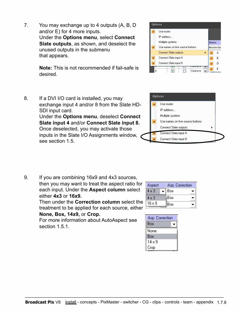
install - concepts - PixMaster - switcher - CG - clips - controls - team - appendix Broadcast Pix V8 1.7.8
7. You may exchange up to 4 outputs (A, B, D and/or E) for 4 more inputs. Under the Options menu, select Connect Slate outputs, as shown, and deselect the unused outputs in the submenu that appears.
Note: This is not recommended if fail-safe is desired.
8. If a DVI I/O card is installed, you may exchange input 4 and/or 8 from the Slate HD-SDI input card. Under the Options menu, deselect Connect Slate input 4 and/or Connect Slate input 8. Once deselected, you may activate those inputs in the Slate I/O Assignments window, see section 1.5.
9. If you are combining 16x9 and 4x3 sources, then you may want to treat the aspect ratio for each input. Under the Aspect column select either 4x3 or 16x9. Then under the Correction column select the treatment to be applied for each source, either None, Box, 14x9, or Crop. For more information about AutoAspect see section 1.5.1.
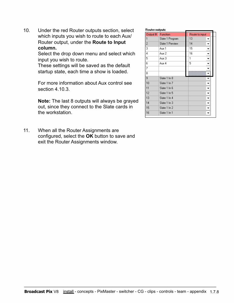
install - concepts - PixMaster - switcher - CG - clips - controls - team - appendix Broadcast Pix V8 1.7.8
10. Under the red Router outputs section, select which inputs you wish to route to each Aux/Router output, under the Route to Input column. Select the drop down menu and select which input you wish to route. These settings will be saved as the default startup state, each time a show is loaded.
For more information about Aux control see section 4.10.3.
Note: The last 8 outputs will always be grayed out, since they connect to the Slate cards in the workstation.
11. When all the Router Assignments are configured, select the OK button to save and exit the Router Assignments window.
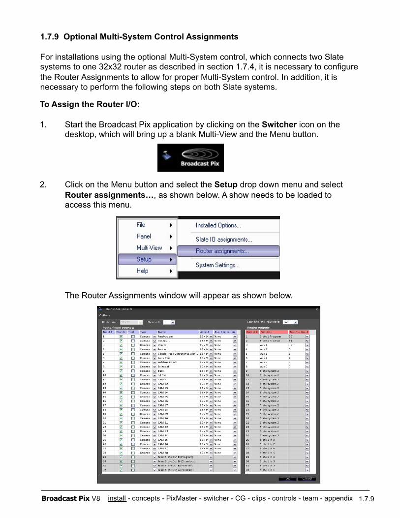
install - concepts - PixMaster - switcher - CG - clips - controls - team - appendix Broadcast Pix V8
To Assign the Router I/O:
1. Start the Broadcast Pix application by clicking on the Switcher icon on the desktop, which will bring up a blank Multi-View and the Menu button.
2. Click on the Menu button and select the Setup drop down menu and select Router assignments…, as shown below. A show needs to be loaded to access this menu.
The Router Assignments window will appear as shown below.
1.7.9 Optional Multi-System Control Assignments
For installations using the optional Multi-System control, which connects two Slate systems to one 32x32 router as described in section 1.7.4, it is necessary to configure the Router Assignments to allow for proper Multi-System control. In addition, it is necessary to perform the following steps on both Slate systems.
1.7.9
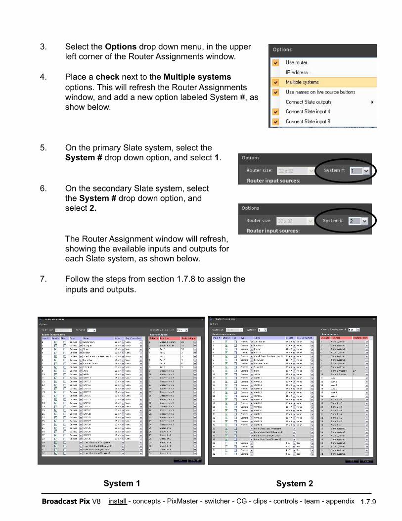
install - concepts - PixMaster - switcher - CG - clips - controls - team - appendix Broadcast Pix V8 1.7.9
3. Select the Options drop down menu, in the upper left corner of the Router Assignments window.
4. Place a check next to the Multiple systems options. This will refresh the Router Assignments window, and add a new option labeled System #, as show below.
5. On the primary Slate system, select the System # drop down option, and select 1.
6. On the secondary Slate system, select the System # drop down option, and select 2.
The Router Assignment window will refresh, showing the available inputs and outputs for each Slate system, as shown below.
7. Follow the steps from section 1.7.8 to assign the inputs and outputs.
System 1 System 2
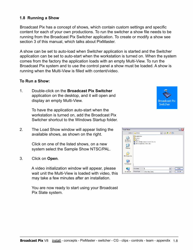
install - concepts - PixMaster - switcher - CG - clips - controls - team - appendix Broadcast Pix V8
1.8 Running a Show
1.8
Broadcast Pix has a concept of shows, which contain custom settings and specific content for each of your own productions. To run the switcher a show file needs to be running from the Broadcast Pix Switcher application. To create or modify a show see section 3 of this manual, which talks about PixMaster.
A show can be set to auto-load when Switcher application is started and the Switcher application can be set to auto-start when the workstation is turned on. When the system comes from the factory the application loads with an empty Multi-View. To run the Broadcast Pix system and to use the control panel a show must be loaded. A show is running when the Multi-View is filled with content/video.
To Run a Show:
1. Double-click on the Broadcast Pix Switcher application on the desktop, and it will open and display an empty Multi-View.
To have the application auto-start when the workstation is turned on, add the Broadcast Pix Switcher shortcut to the Windows Startup folder.
2. The Load Show window will appear listing the available shows, as shown on the right.
Click on one of the listed shows, on a new system select the Sample Show NTSC/PAL.
3. Click on Open.
A video initialization window will appear, please wait unit the Multi-View is loaded with video, this may take a few minutes after an installation.
You are now ready to start using your Broadcast Pix Slate system.
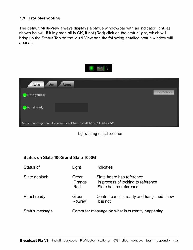
install - concepts - PixMaster - switcher - CG - clips - controls - team - appendix Broadcast Pix V8
1.9 Troubleshooting
1.9
Status of Light Indicates
Slate genlock Green Slate board has reference Orange In process of locking to reference Red Slate has no reference
Panel ready Green Control panel is ready and has joined show - (Grey) It is not
Status message Computer message on what is currently happening
The default Multi-View always displays a status window/bar with an indicator light, as shown below. If it is green all is OK, if not (Red) click on the status light, which will bring up the Status Tab on the Multi-View and the following detailed status window will appear.
Lights during normal operation
Status on Slate 100G and Slate 1000G
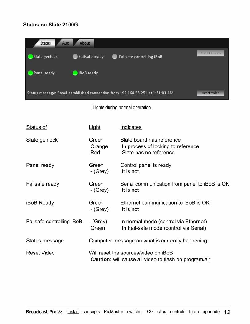
install - concepts - PixMaster - switcher - CG - clips - controls - team - appendix Broadcast Pix V8 1.9
Lights during normal operation
Status on Slate 2100G
Status of Light Indicates
Slate genlock Green Slate board has reference Orange In process of locking to reference Red Slate has no reference
Panel ready Green Control panel is ready - (Grey) It is not
Failsafe ready Green Serial communication from panel to iBoB is OK - (Grey) It is not
iBoB Ready Green Ethernet communication to iBoB is OK - (Grey) It is not
Failsafe controlling iBoB - (Grey) In normal mode (control via Ethernet) Green In Fail-safe mode (control via Serial)
Status message Computer message on what is currently happening
Reset Video Will reset the sources/video on iBoB Caution: will cause all video to flash on program/air
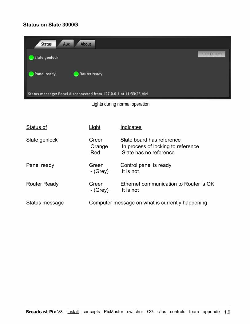
install - concepts - PixMaster - switcher - CG - clips - controls - team - appendix Broadcast Pix V8 1.9
Lights during normal operation
Status on Slate 3000G
Status of Light Indicates
Slate genlock Green Slate board has reference Orange In process of locking to reference Red Slate has no reference
Panel ready Green Control panel is ready - (Grey) It is not
Router Ready Green Ethernet communication to Router is OK - (Grey) It is not
Status message Computer message on what is currently happening
install - concepts - PixMaster - switcher - CG - clips - controls - team - appendix Broadcast Pix V8
1.10 Input Timing & Asynchronous Sources
Reference The Broadcast Pix Switcher requires a reference input from an analog black burst sync generator.
Format Internally, the Broadcast Pix uses the SDI format (SMPTE 259M), and all systems provide SD-SDI digital video I/O with embedded audio (SMPTE 272M ). In addition, Slate can accept HD/SD-SDI formats SMPTE 296M, SMPTE 274M, ITU-R BT601-5, SMPTE 259M and SMPTE 292M. Slate also has analog video I/O conversion for composite, Y/C and component, and its clip store has embedded audio as well as analog stereo audio.
Synchronous Inputs All Slate systems work well with all video inputs that accept a reference input for genlock, including broadcast cameras, tape recorders, servers, etc. The delay through the Slate system on synchronous sources is 1 frame, even if the image is inside a DVE box (picture in picture). In some installations where a stable or wide genlock is not available (i.e. when using a camera/DVD player for reference) there is an option to accommodate this type reference. Select Setup, System Settings and in the Video tab place a check mark next to Narrow Genlock. A restart of the application will be necessary.
Asynchronous Inputs With a precaution, the system will also accept and self time asynchronous sources, such as a DVD player. The precaution is to preview each asynchronous source before taking it to air, which gives the systems the few frames it needs to settle the source down. Unlike synchronous sources, these should not be taken directly to air, because the settling is then visible on program. All direct Slate live Inputs accept asynchronous inputs, and on the inputs coming from the iBoB, inputs 1 through 6 accept asynchronous sources. The delay through the Slate system on asynchronous sources is 2 frames. On all Slate HD systems to allow asynchronous inputs, select Setup, System Settings and in the HDIO tab place a check mark next to Allow A-Sync sources.
HD Inputs The HD I/O card accepts both SD and HD video signals and processes all video at 486p/576p. Although the HD card can accept both Synchronous and Asynchronous sources, it is advised to use genlocked sources to reduce the amount of the delay in the system. In addition to the above delay, there is 1 frame of delay to scale the video coming in and 1 more frame of delay to scale video going out. A complete genlocked system will have a total of 3 frames of delay, a complete non genlocked system will have a total of 4 frames of delay. See the next page for a complete listing of possible delay.
1.10
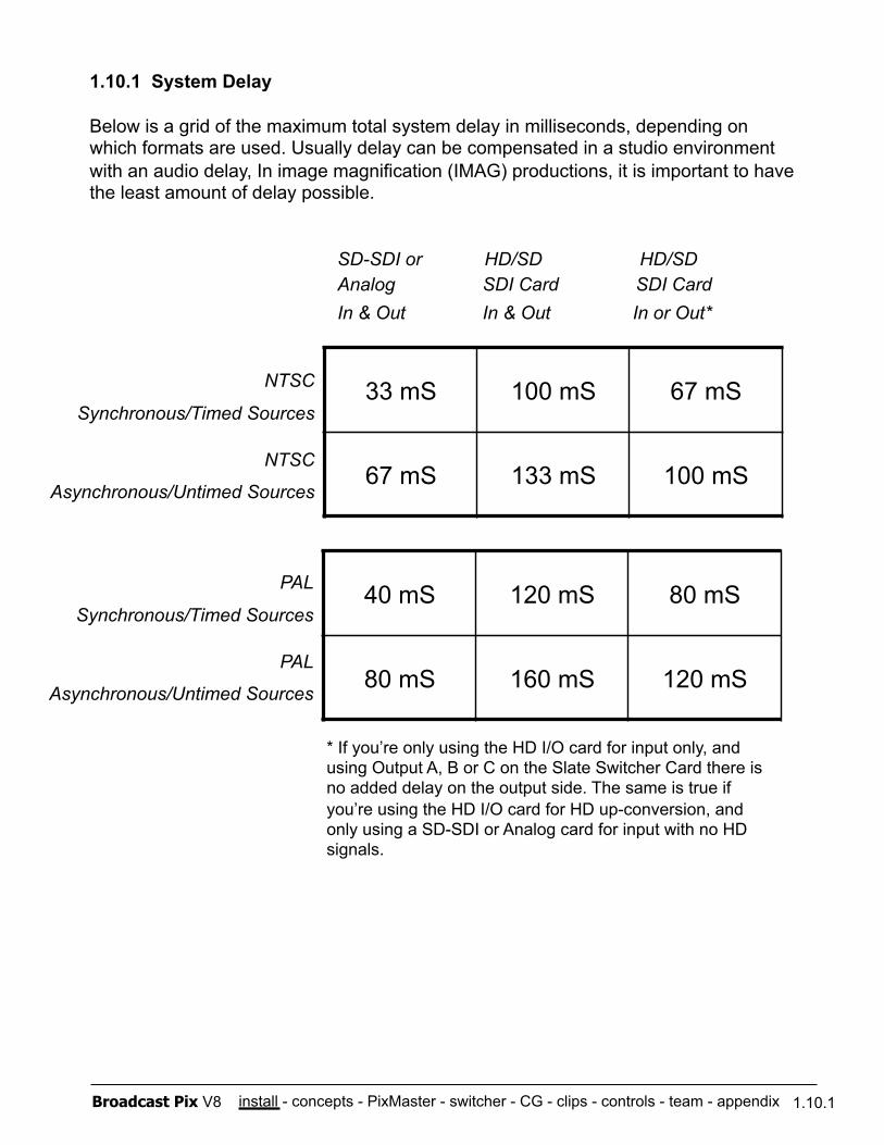
install - concepts - PixMaster - switcher - CG - clips - controls - team - appendix Broadcast Pix V8
1.10.1 System Delay
Below is a grid of the maximum total system delay in milliseconds, depending on which formats are used. Usually delay can be compensated in a studio environment with an audio delay, In image magnification (IMAG) productions, it is important to have the least amount of delay possible.
1.10.1
NTSC
Synchronous/Timed Sources
NTSC
Asynchronous/Untimed Sources
SD-SDI or HD/SD HD/SD Analog SDI Card SDI Card In & Out In & Out In or Out*
* If you’re only using the HD I/O card for input only, and using Output A, B or C on the Slate Switcher Card there is no added delay on the output side. The same is true if you’re using the HD I/O card for HD up-conversion, and only using a SD-SDI or Analog card for input with no HD signals.
33 mS 100 mS 67 mS
67 mS 133 mS 100 mS
40 mS 120 mS 80 mS
80 mS 160 mS 120 mS
PAL
Synchronous/Timed Sources
PAL
Asynchronous/Untimed Sources
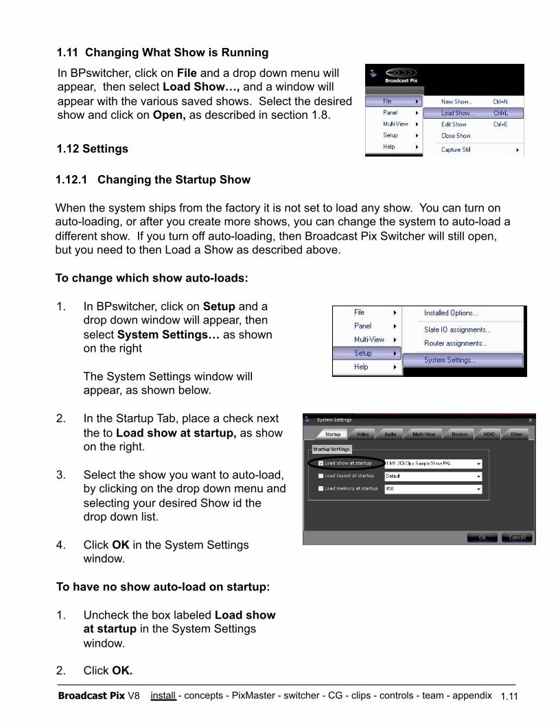
install - concepts - PixMaster - switcher - CG - clips - controls - team - appendix Broadcast Pix V8
1.12.1 Changing the Startup Show
When the system ships from the factory it is not set to load any show. You can turn on auto-loading, or after you create more shows, you can change the system to auto-load a different show. If you turn off auto-loading, then Broadcast Pix Switcher will still open, but you need to then Load a Show as described above.
To change which show auto-loads:
1.11
In BPswitcher, click on File and a drop down menu will appear, then select Load Show…, and a window will appear with the various saved shows. Select the desired show and click on Open, as described in section 1.8.
1.11 Changing What Show is Running
1. In BPswitcher, click on Setup and a drop down window will appear, then select System Settings… as shown on the right
The System Settings window will appear, as shown below.
2. In the Startup Tab, place a check next the to Load show at startup, as show on the right.
3. Select the show you want to auto-load, by clicking on the drop down menu and selecting your desired Show id the drop down list.
4. Click OK in the System Settings window.
To have no show auto-load on startup:
1. Uncheck the box labeled Load show at startup in the System Settings window.
2. Click OK.
1.12 Settings
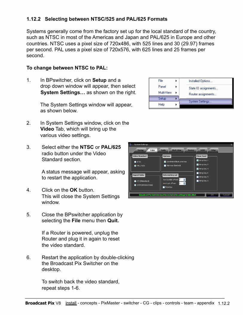
install - concepts - PixMaster - switcher - CG - clips - controls - team - appendix Broadcast Pix V8 1.12.2
1.12.2 Selecting between NTSC/525 and PAL/625 Formats
Systems generally come from the factory set up for the local standard of the country, such as NTSC in most of the Americas and Japan and PAL/625 in Europe and other countries. NTSC uses a pixel size of 720x486, with 525 lines and 30 (29.97) frames per second. PAL uses a pixel size of 720x576, with 625 lines and 25 frames per second.
To change between NTSC to PAL:
1. In BPswitcher, click on Setup and a drop down window will appear, then select System Settings… as shown on the right.
The System Settings window will appear, as shown below.
2. In System Settings window, click on the Video Tab, which will bring up the various video settings.
3. Select either the NTSC or PAL/625 radio button under the Video Standard section.
A status message will appear, asking to restart the application.
4. Click on the OK button. This will close the System Settings window.
5. Close the BPswitcher application by selecting the File menu then Quit.
If a Router is powered, unplug the Router and plug it in again to reset the video standard.
6. Restart the application by double-clicking the Broadcast Pix Switcher on the desktop.
To switch back the video standard, repeat steps 1-6.
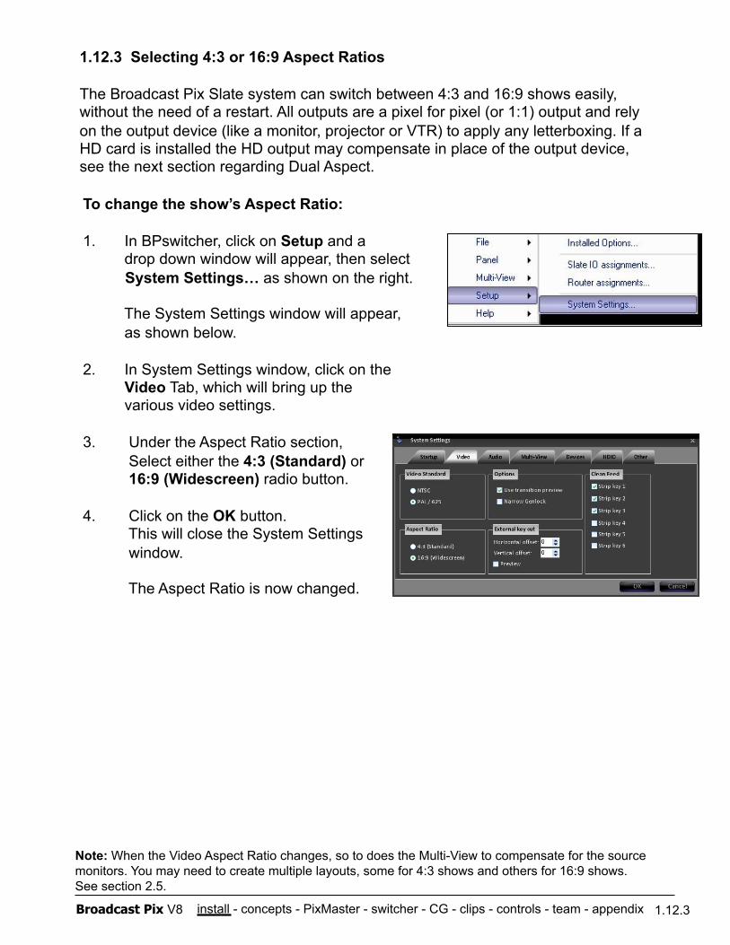
install - concepts - PixMaster - switcher - CG - clips - controls - team - appendix Broadcast Pix V8 1.12.3
1.12.3 Selecting 4:3 or 16:9 Aspect Ratios
The Broadcast Pix Slate system can switch between 4:3 and 16:9 shows easily, without the need of a restart. All outputs are a pixel for pixel (or 1:1) output and rely on the output device (like a monitor, projector or VTR) to apply any letterboxing. If a HD card is installed the HD output may compensate in place of the output device, see the next section regarding Dual Aspect.
To change the show’s Aspect Ratio:
1. In BPswitcher, click on Setup and a drop down window will appear, then select System Settings… as shown on the right.
The System Settings window will appear, as shown below.
2. In System Settings window, click on the Video Tab, which will bring up the various video settings.
3. Under the Aspect Ratio section, Select either the 4:3 (Standard) or 16:9 (Widescreen) radio button.
4. Click on the OK button. This will close the System Settings window.
The Aspect Ratio is now changed.
Note: When the Video Aspect Ratio changes, so to does the Multi-View to compensate for the source monitors. You may need to create multiple layouts, some for 4:3 shows and others for 16:9 shows. See section 2.5.
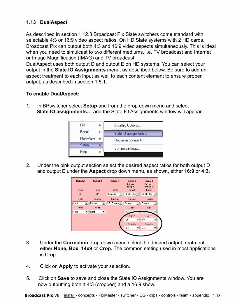
install - concepts - PixMaster - switcher - CG - clips - controls - team - appendix Broadcast Pix V8 1.13
1.13 DualAspect
As described in section 1.12.3 Broadcast Pix Slate switchers come standard with selectable 4:3 or 16:9 video aspect ratios. On HD Slate systems with 2 HD cards, Broadcast Pix can output both 4:3 and 16:9 video aspects simultaneously. This is ideal when you need to simulcast to two different mediums, i.e. TV broadcast and Internet or Image Magnification (IMAG) and TV broadcast. DualAspect uses both output D and output E on HD systems. You can select your output in the Slate IO Assignments menu, as described below. Be sure to add an aspect treatment to each input as well to each content element to ensure proper output, as described in section 1.5.1.
To enable DualAspect:
1. In BPswitcher select Setup and from the drop down menu and select Slate IO assignments… and the Slate IO Assignments window will appear.
2. Under the pink output section select the desired aspect ratios for both output D and output E under the Aspect drop down menu, as shown, either 16:9 or 4:3.
3. Under the Correction drop down menu select the desired output treatment, either None, Box, 14x9 or Crop. The common setting used in most applications is Crop.
4. Click on Apply to activate your selection.
5. Click on Save to save and close the Slate IO Assignments window. You are now outputting both a 4:3 (cropped) and a 16:9 show.
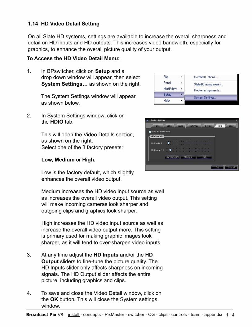
install - concepts - PixMaster - switcher - CG - clips - controls - team - appendix Broadcast Pix V8 1.14
1.14 HD Video Detail Setting
On all Slate HD systems, settings are available to increase the overall sharpness and detail on HD inputs and HD outputs. This increases video bandwidth, especially for graphics, to enhance the overall picture quality of your output.
To Access the HD Video Detail Menu:
1. In BPswitcher, click on Setup and a drop down window will appear, then select System Settings… as shown on the right.
The System Settings window will appear, as shown below.
2. In System Settings window, click on the HDIO tab.
This will open the Video Details section, as shown on the right. Select one of the 3 factory presets:
Low, Medium or High.
Low is the factory default, which slightly enhances the overall video output.
Medium increases the HD video input source as well as increases the overall video output. This setting will make incoming cameras look sharper and outgoing clips and graphics look sharper.
High increases the HD video input source as well as increase the overall video output more. This setting is primary used for making graphic images look sharper, as it will tend to over-sharpen video inputs.
3. At any time adjust the HD Inputs and/or the HD Output sliders to fine-tune the picture quality. The HD Inputs slider only affects sharpness on incoming signals. The HD Output slider affects the entire picture, including graphics and clips.
4. To save and close the Video Detail window, click on the OK button. This will close the System settings window.
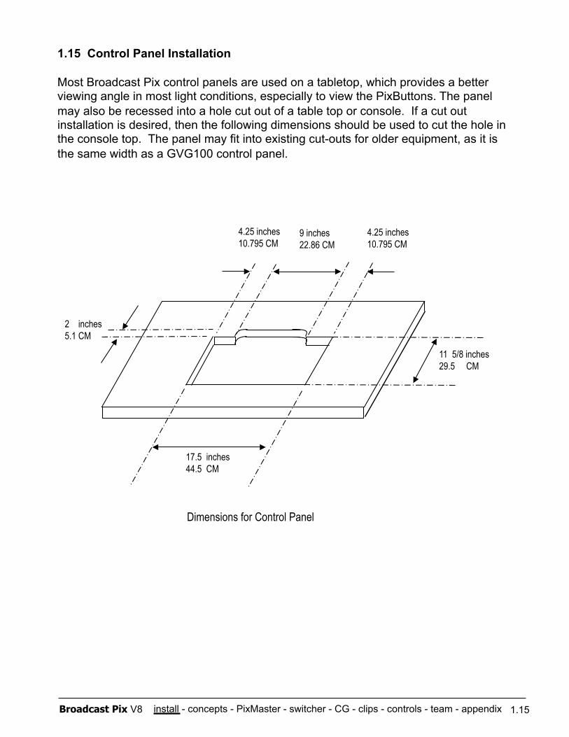
install - concepts - PixMaster - switcher - CG - clips - controls - team - appendix Broadcast Pix V8
1.15 Control Panel Installation
Most Broadcast Pix control panels are used on a tabletop, which provides a better viewing angle in most light conditions, especially to view the PixButtons. The panel may also be recessed into a hole cut out of a table top or console. If a cut out installation is desired, then the following dimensions should be used to cut the hole in the console top. The panel may fit into existing cut-outs for older equipment, as it is the same width as a GVG100 control panel.
17.5 inches 44.5 CM
11 5/8 inches 29.5 CM
4.25 inches 10.795 CM
2 inches 5.1 CM
Dimensions for Control Panel
4.25 inches 10.795 CM
9 inches 22.86 CM
1.15
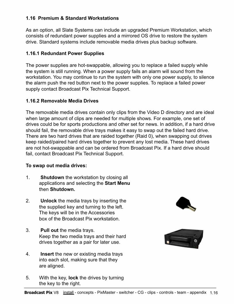
install - concepts - PixMaster - switcher - CG - clips - controls - team - appendix Broadcast Pix V8 1.16
1.16 Premium & Standard Workstations
As an option, all Slate Systems can include an upgraded Premium Workstation, which consists of redundant power supplies and a mirrored OS drive to restore the system drive. Standard systems include removable media drives plus backup software.
1.16.1 Redundant Power Supplies
The power supplies are hot-swappable, allowing you to replace a failed supply while the system is still running. When a power supply fails an alarm will sound from the workstation. You may continue to run the system with only one power supply, to silence the alarm push the red button next to the power supplies. To replace a failed power supply contact Broadcast Pix Technical Support.
1.16.2 Removable Media Drives
The removable media drives contain only clips from the Video D directory and are ideal when large amount of clips are needed for multiple shows. For example, one set of drives could be for sports productions and other set for news. In addition, if a hard drive should fail, the removable drive trays makes it easy to swap out the failed hard drive. There are two hard drives that are raided together (Raid 0), when swapping out drives keep raided/paired hard drives together to prevent any lost media. These hard drives are not hot-swappable and can be ordered from Broadcast Pix. If a hard drive should fail, contact Broadcast Pix Technical Support.
To swap out media drives:
1. Shutdown the workstation by closing all applications and selecting the Start Menu then Shutdown.
2. Unlock the media trays by inserting the the supplied key and turning to the left. The keys will be in the Accessories box of the Broadcast Pix workstation.
3. Pull out the media trays. Keep the two media trays and their hard drives together as a pair for later use.
4. Insert the new or existing media trays into each slot, making sure that they are aligned.
5. With the key, lock the drives by turning the key to the right.
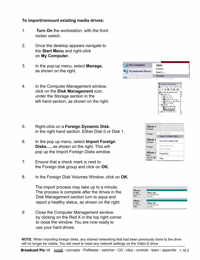
install - concepts - PixMaster - switcher - CG - clips - controls - team - appendix Broadcast Pix V8 1.16.2
To import/remount existing media drives:
1. Turn On the workstation, with the front rocker switch.
2. Once the desktop appears navigate to the Start Menu and right-click on My Computer.
3. In the pop-up menu, select Manage, as shown on the right.
4. In the Computer Management window, click on the Disk Management icon, under the Storage section in the left hand section, as shown on the right.
5. Right-click on a Foreign Dynamic Disk, in the right hand section. Either Disk 0 or Disk 1.
6. In the pop up menu, select Import Foreign Disks…, as shown on the right. This will
pop up the Import Foreign Disks window.
7. Ensure that a check mark is next to the Foreign disk group and click on OK.
8. In the Foreign Disk Volumes Window, click on OK.
The import process may take up to a minute. The process is complete after the drives in the Disk Management section turn to aqua and report a healthy status, as shown on the right.
9 Close the Computer Management window by clicking on the Red X in the top right corner. to close the window. You are now ready to use your hard drives.
NOTE: When importing foreign disks, any shared networking that had been previously done to the drive will no longer be visible. You will need to reset any network settings on the Video D drive.
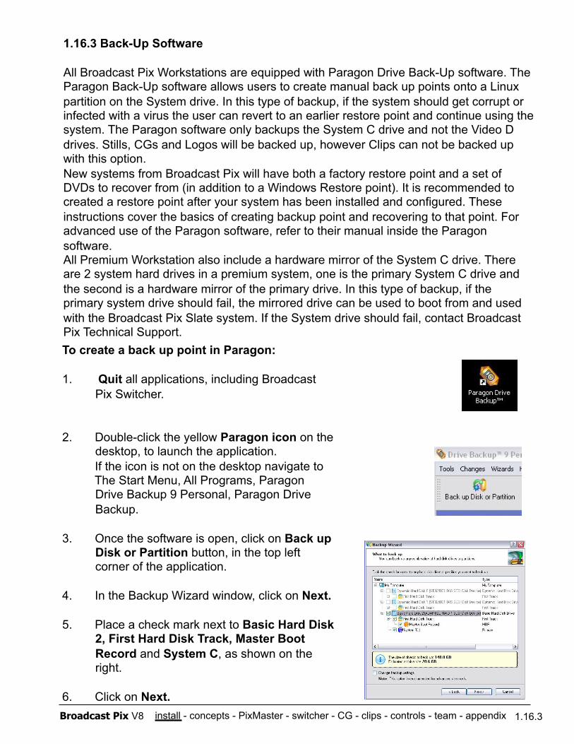
install - concepts - PixMaster - switcher - CG - clips - controls - team - appendix Broadcast Pix V8 1.16.3
1.16.3 Back-Up Software
All Broadcast Pix Workstations are equipped with Paragon Drive Back-Up software. The Paragon Back-Up software allows users to create manual back up points onto a Linux partition on the System drive. In this type of backup, if the system should get corrupt or infected with a virus the user can revert to an earlier restore point and continue using the system. The Paragon software only backups the System C drive and not the Video D drives. Stills, CGs and Logos will be backed up, however Clips can not be backed up with this option. New systems from Broadcast Pix will have both a factory restore point and a set of DVDs to recover from (in addition to a Windows Restore point). It is recommended to created a restore point after your system has been installed and configured. These instructions cover the basics of creating backup point and recovering to that point. For advanced use of the Paragon software, refer to their manual inside the Paragon software. All Premium Workstation also include a hardware mirror of the System C drive. There are 2 system hard drives in a premium system, one is the primary System C drive and the second is a hardware mirror of the primary drive. In this type of backup, if the primary system drive should fail, the mirrored drive can be used to boot from and used with the Broadcast Pix Slate system. If the System drive should fail, contact Broadcast Pix Technical Support. To create a back up point in Paragon:
1. Quit all applications, including Broadcast Pix Switcher.
2. Double-click the yellow Paragon icon on the desktop, to launch the application.
If the icon is not on the desktop navigate to The Start Menu, All Programs, Paragon Drive Backup 9 Personal, Paragon Drive Backup.
3. Once the software is open, click on Back up Disk or Partition button, in the top left corner of the application.
4. In the Backup Wizard window, click on Next.
5. Place a check mark next to Basic Hard Disk 2, First Hard Disk Track, Master Boot Record and System C, as shown on the right.
6. Click on Next.
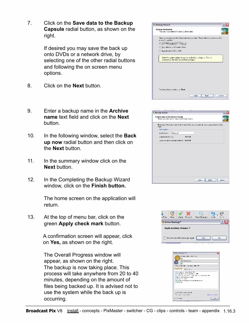
install - concepts - PixMaster - switcher - CG - clips - controls - team - appendix Broadcast Pix V8 1.16.3
7. Click on the Save data to the Backup Capsule radial button, as shown on the right.
If desired you may save the back up onto DVDs or a network drive, by selecting one of the other radial buttons and following the on screen menu options.
8. Click on the Next button.
9. Enter a backup name in the Archive name text field and click on the Next button.
10. In the following window, select the Back up now radial button and then click on the Next button.
11. In the summary window click on the Next button.
12. In the Completing the Backup Wizard window, click on the Finish button.
The home screen on the application will return.
13. At the top of menu bar, click on the green Apply check mark button.
A confirmation screen will appear, click on Yes, as shown on the right.
The Overall Progress window will appear, as shown on the right. The backup is now taking place. This process will take anywhere from 20 to 40 minutes, depending on the amount of files being backed up. It is advised not to use the system while the back up is occurring.
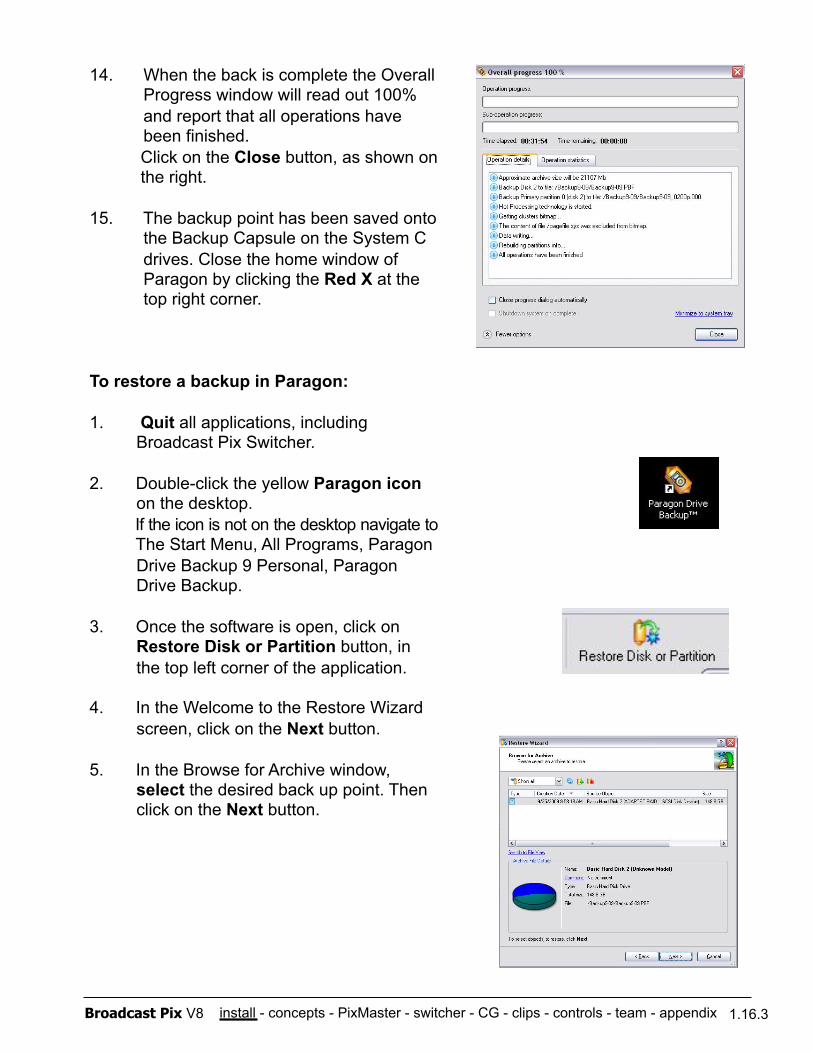
install - concepts - PixMaster - switcher - CG - clips - controls - team - appendix Broadcast Pix V8 1.16.3
14. When the back is complete the Overall Progress window will read out 100% and report that all operations have been finished. Click on the Close button, as shown on the right.
15. The backup point has been saved onto the Backup Capsule on the System C drives. Close the home window of Paragon by clicking the Red X at the top right corner.
To restore a backup in Paragon:
1. Quit all applications, including Broadcast Pix Switcher.
2. Double-click the yellow Paragon icon on the desktop.
If the icon is not on the desktop navigate to The Start Menu, All Programs, Paragon Drive Backup 9 Personal, Paragon Drive Backup.
3. Once the software is open, click on Restore Disk or Partition button, in the top left corner of the application.
4. In the Welcome to the Restore Wizard screen, click on the Next button.
5. In the Browse for Archive window, select the desired back up point. Then click on the Next button.
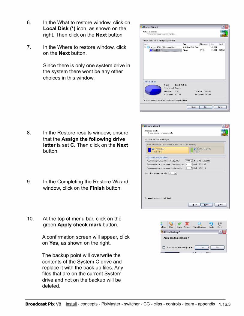
install - concepts - PixMaster - switcher - CG - clips - controls - team - appendix Broadcast Pix V8 1.16.3
6. In the What to restore window, click on Local Disk (*) icon, as shown on the right. Then click on the Next button
7. In the Where to restore window, click on the Next button.
Since there is only one system drive in the system there wont be any other choices in this window.
8. In the Restore results window, ensure that the Assign the following drive letter is set C. Then click on the Next button.
9. In the Completing the Restore Wizard window, click on the Finish button.
10. At the top of menu bar, click on the green Apply check mark button.
A confirmation screen will appear, click on Yes, as shown on the right.
The backup point will overwrite the contents of the System C drive and replace it with the back up files. Any files that are on the current System drive and not on the backup will be deleted.
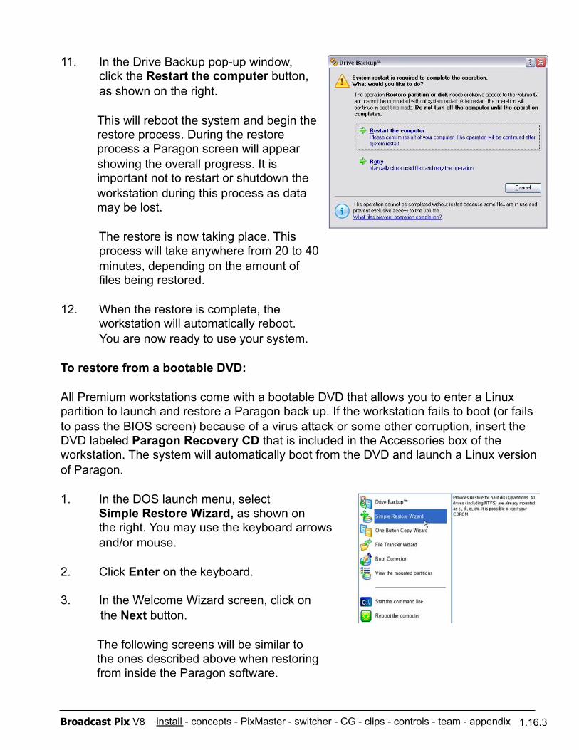
install - concepts - PixMaster - switcher - CG - clips - controls - team - appendix Broadcast Pix V8 1.16.3
11. In the Drive Backup pop-up window, click the Restart the computer button, as shown on the right.
This will reboot the system and begin the restore process. During the restore process a Paragon screen will appear showing the overall progress. It is important not to restart or shutdown the workstation during this process as data may be lost.
The restore is now taking place. This process will take anywhere from 20 to 40 minutes, depending on the amount of files being restored.
12. When the restore is complete, the workstation will automatically reboot. You are now ready to use your system.
To restore from a bootable DVD:
All Premium workstations come with a bootable DVD that allows you to enter a Linux partition to launch and restore a Paragon back up. If the workstation fails to boot (or fails to pass the BIOS screen) because of a virus attack or some other corruption, insert the DVD labeled Paragon Recovery CD that is included in the Accessories box of the workstation. The system will automatically boot from the DVD and launch a Linux version of Paragon.
1. In the DOS launch menu, select Simple Restore Wizard, as shown on the right. You may use the keyboard arrows and/or mouse.
2. Click Enter on the keyboard.
3. In the Welcome Wizard screen, click on the Next button.
The following screens will be similar to the ones described above when restoring from inside the Paragon software.
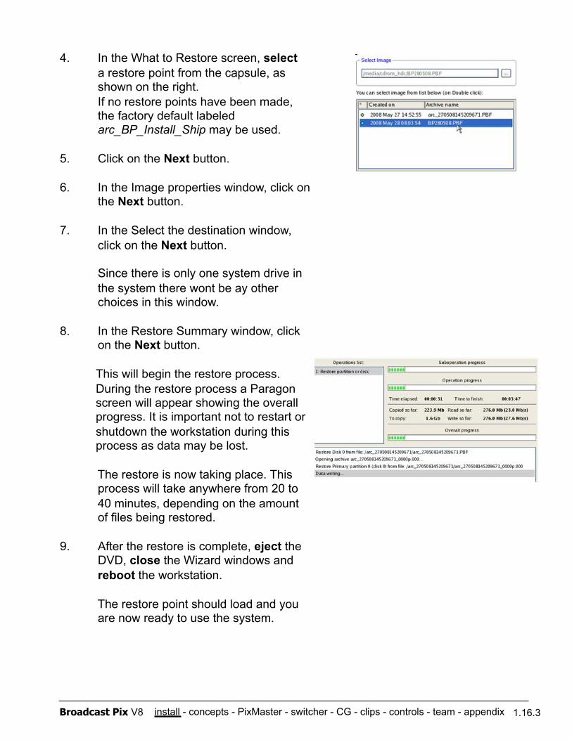
install - concepts - PixMaster - switcher - CG - clips - controls - team - appendix Broadcast Pix V8 1.16.3
4. In the What to Restore screen, select a restore point from the capsule, as shown on the right. If no restore points have been made, the factory default labeled arc_BP_Install_Ship may be used.
5. Click on the Next button.
6. In the Image properties window, click on the Next button.
7. In the Select the destination window, click on the Next button.
Since there is only one system drive in the system there wont be ay other choices in this window.
8. In the Restore Summary window, click on the Next button.
This will begin the restore process. During the restore process a Paragon screen will appear showing the overall progress. It is important not to restart or shutdown the workstation during this process as data may be lost.
The restore is now taking place. This process will take anywhere from 20 to 40 minutes, depending on the amount of files being restored.
9. After the restore is complete, eject the DVD, close the Wizard windows and reboot the workstation.
The restore point should load and you are now ready to use the system.

install - concepts - PixMaster - switcher - CG - clips - controls - team - appendix Broadcast Pix V8 1.16.3
To delete a restore point in Paragon:
1. Quit all applications, including Broadcast Pix Switcher.
2. Double-click the yellow Paragon icon on the desktop.
If the icon is not on the desktop navigate to The Start Menu, All Programs, Paragon Drive Backup 9 Personal, Paragon Drive Backup.
3. Click on the Archives Tab, on the top of the application, as shown on the right.
4. At the bottom of the Archives window a list of saved back up points will be visible. Select the desired back up point, it will highlight grey.
5. Click on the Delete the selected archive button, as shown on the right.
6. A pop-up warning will appear to confirm deletion. Click on the Delete button to permanently delete the backup file. The file is erased from the backup capsule.
Since the Backup Capsule on the System drive is only 70GB, the capsule may fill up with multiple restore points.
Using the Desktop Shortcuts:
On new systems from Broadcast Pix, 4 desktop icons are available as shortcuts for both creating and resorting a backup. There are 2 shortcuts to create a backup, Backup 1 and Backup 2. These backups automate the above steps without the need of entering the Paragon application. There are 2 shortcuts to restore from the each backup, Restore 1 (which corresponds with Backup 1) and Restore 2 (which corresponds with Backup 2). To run a selected shortcut, ensure that no applications or tasks are running and double-click the icon and a script will run in the background. Keep in mind these shortcuts offer a quick and easy recovery method, for more advanced recovery refer to the Paragon Backup manual.
install - concepts - PixMaster - switcher - CG - clips - controls - team - appendix Broadcast Pix V8
2.1 Broadcast Pix Features
Integrated Broadcast Studio Contains an entire control room of devices including: switcher, clip stores, character generator still stores, logos, DVEs, monitoring, optional audio, camera and external DDR control.
Pristine SDI Video Create superb digital video (SMPTE 259M) with 3 keyers (upgradeable to 6 keyers), background video, and a second background when transitioning. Slate 2100G adds iBoB DSK.
Versatile Control Panel Slate 1000G, 2100G and 3000G feature a fast- action control panel enables rapid control of all sources, devices and keys
Confidence of On-Button Content Execute with confidence, as not only the device type, but the actual content element is displayed on PixButtons for every source and keyer, as well as on the Multi-View.
Personal Studio Now one person can create engaging live video that used to require a team of operators
Grow to a Team Studio For complex production add more panels, as described in the team section
Fail-Safe On-Air Multiple redundancies always keep your show on-air. Redundant routing, panels and power.
2.1
Section 2: Broadcast Pix Concepts

install - concepts - PixMaster - switcher - CG - clips - controls - team - appendix Broadcast Pix V8
2.1.1 Video Flow Diagram
2.1.1
Every Broadcast Pix Slate system has an integrated workstation, which enables the switching matrix to be extended into the computer, so it can access disk space for clips, graphics and animations.
As shown in the above diagram, sources may come in from a wide range of creation points. From live video of any format to video and graphic files over a network, the Broadcast Pix Slate system improves your workflow.
Video is then processed in the Slate input video card, which enables up to 6 video keyers with DVEs, 8 chromakeys/luma keys and a wide-range of mix effects.
Sources are then monitored on the integrated Multi-View and outputs through the Slate outputs cards in a wide range of standard and high-definition formats.
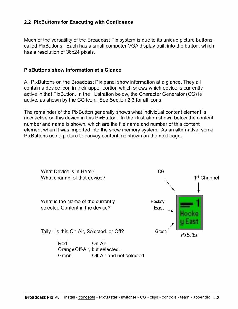
install - concepts - PixMaster - switcher - CG - clips - controls - team - appendix Broadcast Pix V8
2.2 PixButtons for Executing with Confidence
Much of the versatility of the Broadcast Pix system is due to its unique picture buttons, called PixButtons. Each has a small computer VGA display built into the button, which has a resolution of 36x24 pixels.
PixButtons show Information at a Glance
All PixButtons on the Broadcast Pix panel show information at a glance. They all contain a device icon in their upper portion which shows which device is currently active in that PixButton. In the illustration below, the Character Generator (CG) is active, as shown by the CG icon. See Section 2.3 for all icons.
The remainder of the PixButton generally shows what individual content element is now active on this device in this PixButton. In the illustration shown below the content number and name is shown, which are the file name and number of this content element when it was imported into the show memory system. As an alternative, some PixButtons use a picture to convey content, as shown on the next page.
What Device is in Here? CG What channel of that device? 1st Channel
What is the Name of the currently Hockey selected Content in the device? East
Tally - Is this On-Air, Selected, or Off? Green Red On-Air Orange Off-Air, but selected. Green Off-Air and not selected.
PixButton
2.2
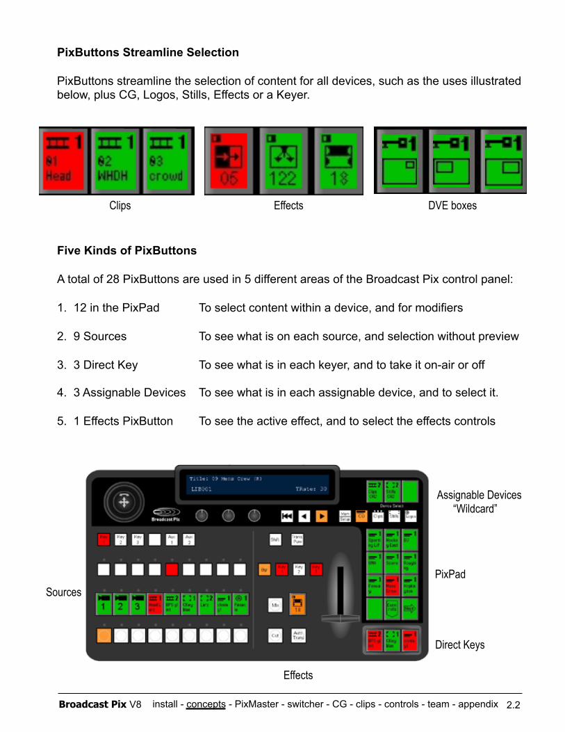
install - concepts - PixMaster - switcher - CG - clips - controls - team - appendix Broadcast Pix V8
PixButtons Streamline Selection
PixButtons streamline the selection of content for all devices, such as the uses illustrated below, plus CG, Logos, Stills, Effects or a Keyer.
Five Kinds of PixButtons
A total of 28 PixButtons are used in 5 different areas of the Broadcast Pix control panel:
1. 12 in the PixPad To select content within a device, and for modifiers
2. 9 Sources To see what is on each source, and selection without preview
3. 3 Direct Key To see what is in each keyer, and to take it on-air or off
4. 3 Assignable Devices To see what is in each assignable device, and to select it.
5. 1 Effects PixButton To see the active effect, and to select the effects controls
Clips Effects DVE boxes
Sources
Direct Keys
Assignable Devices “Wildcard”
PixPad
Effects
2.2
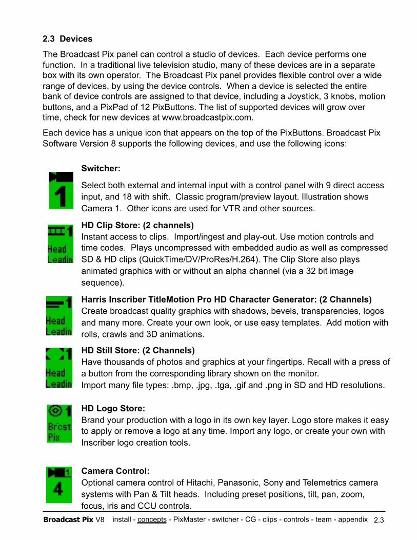
install - concepts - PixMaster - switcher - CG - clips - controls - team - appendix Broadcast Pix V8
2.3 Devices
The Broadcast Pix panel can control a studio of devices. Each device performs one function. In a traditional live television studio, many of these devices are in a separate box with its own operator. The Broadcast Pix panel provides flexible control over a wide range of devices, by using the device controls. When a device is selected the entire bank of device controls are assigned to that device, including a Joystick, 3 knobs, motion buttons, and a PixPad of 12 PixButtons. The list of supported devices will grow over time, check for new devices at www.broadcastpix.com.
Each device has a unique icon that appears on the top of the PixButtons. Broadcast Pix Software Version 8 supports the following devices, and use the following icons:
Switcher:
Select both external and internal input with a control panel with 9 direct access input, and 18 with shift. Classic program/preview layout. Illustration shows Camera 1. Other icons are used for VTR and other sources.
HD Clip Store: (2 channels) Instant access to clips. Import/ingest and play-out. Use motion controls and time codes. Plays uncompressed with embedded audio as well as compressed SD & HD clips (QuickTime/DV/ProRes/H.264). The Clip Store also plays animated graphics with or without an alpha channel (via a 32 bit image sequence).
Harris Inscriber TitleMotion Pro HD Character Generator: (2 Channels) Create broadcast quality graphics with shadows, bevels, transparencies, logos and many more. Create your own look, or use easy templates. Add motion with rolls, crawls and 3D animations.
HD Still Store: (2 Channels) Have thousands of photos and graphics at your fingertips. Recall with a press of a button from the corresponding library shown on the monitor. Import many file types: .bmp, .jpg, .tga, .gif and .png in SD and HD resolutions.
HD Logo Store: Brand your production with a logo in its own key layer. Logo store makes it easy to apply or remove a logo at any time. Import any logo, or create your own with Inscriber logo creation tools.
Camera Control: Optional camera control of Hitachi, Panasonic, Sony and Telemetrics camera systems with Pan & Tilt heads. Including preset positions, tilt, pan, zoom, focus, iris and CCU controls.
2.3
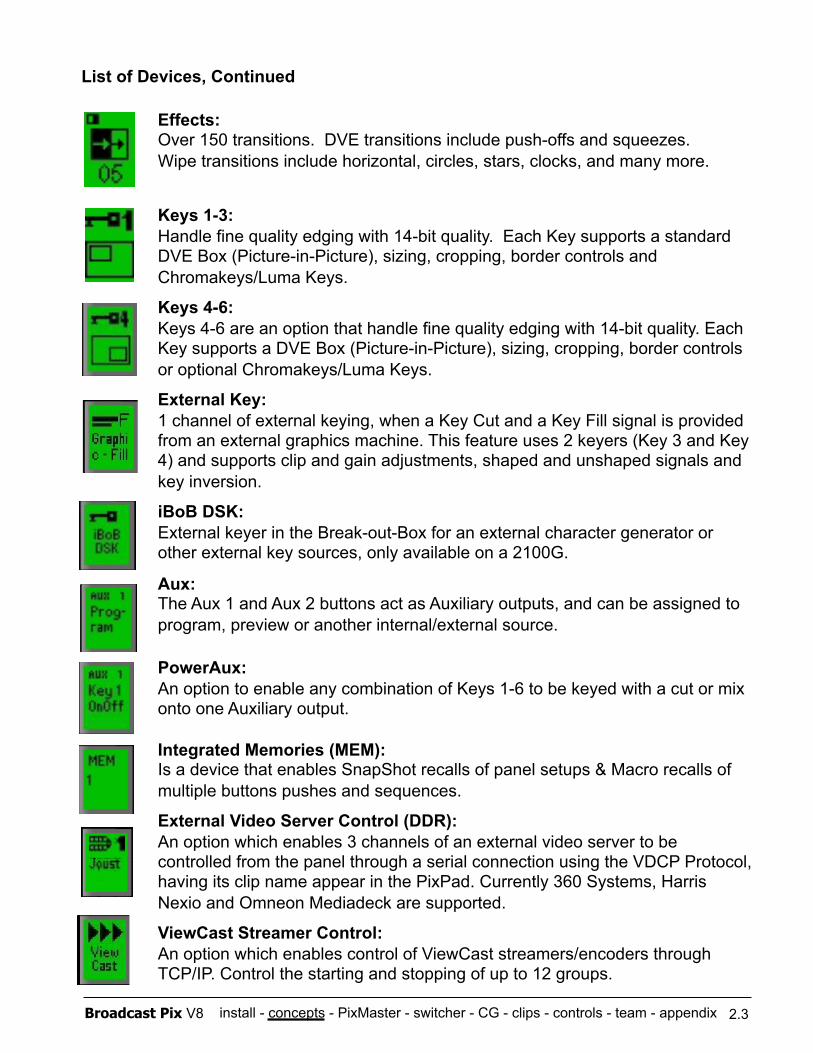
install - concepts - PixMaster - switcher - CG - clips - controls - team - appendix Broadcast Pix V8
List of Devices, Continued
Effects: Over 150 transitions. DVE transitions include push-offs and squeezes. Wipe transitions include horizontal, circles, stars, clocks, and many more.
Keys 1-3: Handle fine quality edging with 14-bit quality. Each Key supports a standard DVE Box (Picture-in-Picture), sizing, cropping, border controls and Chromakeys/Luma Keys.
Keys 4-6: Keys 4-6 are an option that handle fine quality edging with 14-bit quality. Each Key supports a DVE Box (Picture-in-Picture), sizing, cropping, border controls or optional Chromakeys/Luma Keys.
External Key: 1 channel of external keying, when a Key Cut and a Key Fill signal is provided from an external graphics machine. This feature uses 2 keyers (Key 3 and Key 4) and supports clip and gain adjustments, shaped and unshaped signals and key inversion.
iBoB DSK: External keyer in the Break-out-Box for an external character generator or other external key sources, only available on a 2100G.
Aux: The Aux 1 and Aux 2 buttons act as Auxiliary outputs, and can be assigned to program, preview or another internal/external source.
PowerAux: An option to enable any combination of Keys 1-6 to be keyed with a cut or mix onto one Auxiliary output.
Integrated Memories (MEM): Is a device that enables SnapShot recalls of panel setups & Macro recalls of multiple buttons pushes and sequences.
External Video Server Control (DDR): An option which enables 3 channels of an external video server to be controlled from the panel through a serial connection using the VDCP Protocol, having its clip name appear in the PixPad. Currently 360 Systems, Harris Nexio and Omneon Mediadeck are supported.
ViewCast Streamer Control:
An option which enables control of ViewCast streamers/encoders through TCP/IP. Control the starting and stopping of up to 12 groups.
2.3
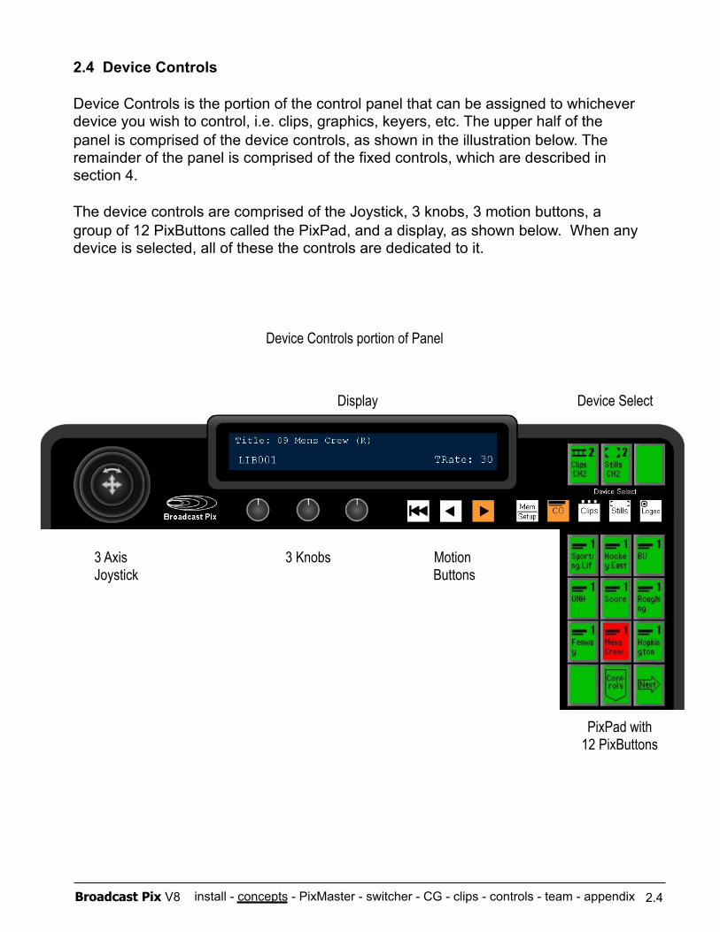
install - concepts - PixMaster - switcher - CG - clips - controls - team - appendix Broadcast Pix V8
2.4 Device Controls
Device Controls is the portion of the control panel that can be assigned to whichever device you wish to control, i.e. clips, graphics, keyers, etc. The upper half of the panel is comprised of the device controls, as shown in the illustration below. The remainder of the panel is comprised of the fixed controls, which are described in section 4.
The device controls are comprised of the Joystick, 3 knobs, 3 motion buttons, a group of 12 PixButtons called the PixPad, and a display, as shown below. When any device is selected, all of these the controls are dedicated to it.
PixPad with 12 PixButtons
Display Device Select
3 Axis 3 Knobs Motion Joystick Buttons
2.4
Device Controls portion of Panel
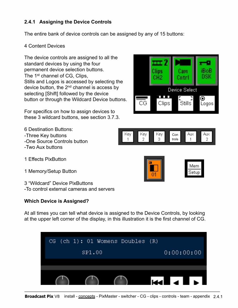
install - concepts - PixMaster - switcher - CG - clips - controls - team - appendix Broadcast Pix V8
2.4.1 Assigning the Device Controls
The entire bank of device controls can be assigned by any of 15 buttons:
4 Content Devices
The device controls are assigned to all the standard devices by using the four permanent device selection buttons. The 1st channel of CG, Clips, Stills and Logos is accessed by selecting the device button, the 2nd channel is access by selecting [Shift] followed by the device button or through the Wildcard Device buttons.
For specifics on how to assign devices to these 3 wildcard buttons, see section 3.7.3.
6 Destination Buttons: -Three Key buttons -One Source Controls button -Two Aux buttons
1 Effects PixButton
1 Memory/Setup Button
3 “Wildcard” Device PixButtons -To control external cameras and servers
Which Device is Assigned?
At all times you can tell what device is assigned to the Device Controls, by looking at the upper left corner of the display, in this illustration it is the first channel of CG.
2.4.1
Con trols
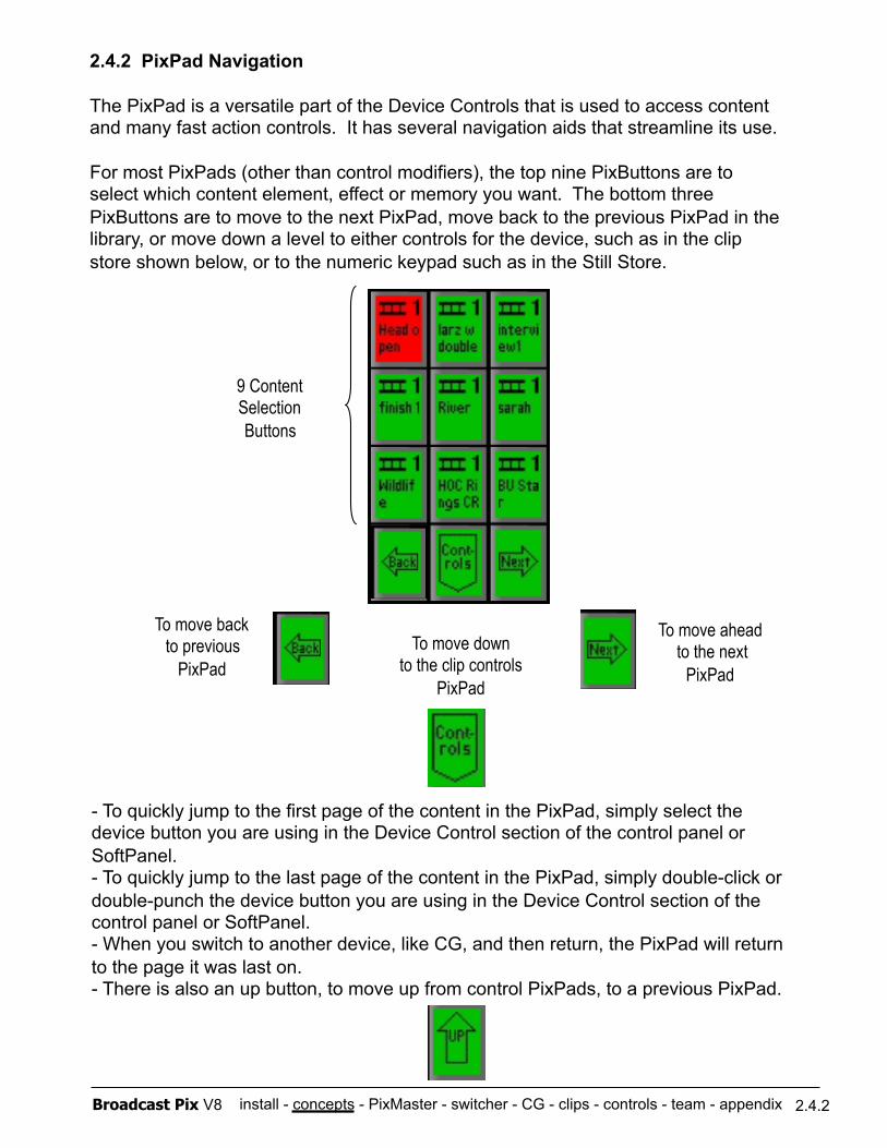
install - concepts - PixMaster - switcher - CG - clips - controls - team - appendix Broadcast Pix V8
2.4.2 PixPad Navigation
The PixPad is a versatile part of the Device Controls that is used to access content and many fast action controls. It has several navigation aids that streamline its use.
For most PixPads (other than control modifiers), the top nine PixButtons are to select which content element, effect or memory you want. The bottom three PixButtons are to move to the next PixPad, move back to the previous PixPad in the library, or move down a level to either controls for the device, such as in the clip store shown below, or to the numeric keypad such as in the Still Store.
9 Content Selection Buttons
To move back to previous
PixPad
To move ahead to the next
PixPad To move down
to the clip controls PixPad
- To quickly jump to the first page of the content in the PixPad, simply select the device button you are using in the Device Control section of the control panel or SoftPanel. - To quickly jump to the last page of the content in the PixPad, simply double-click or double-punch the device button you are using in the Device Control section of the control panel or SoftPanel. - When you switch to another device, like CG, and then return, the PixPad will return to the page it was last on. - There is also an up button, to move up from control PixPads, to a previous PixPad.
2.4.2
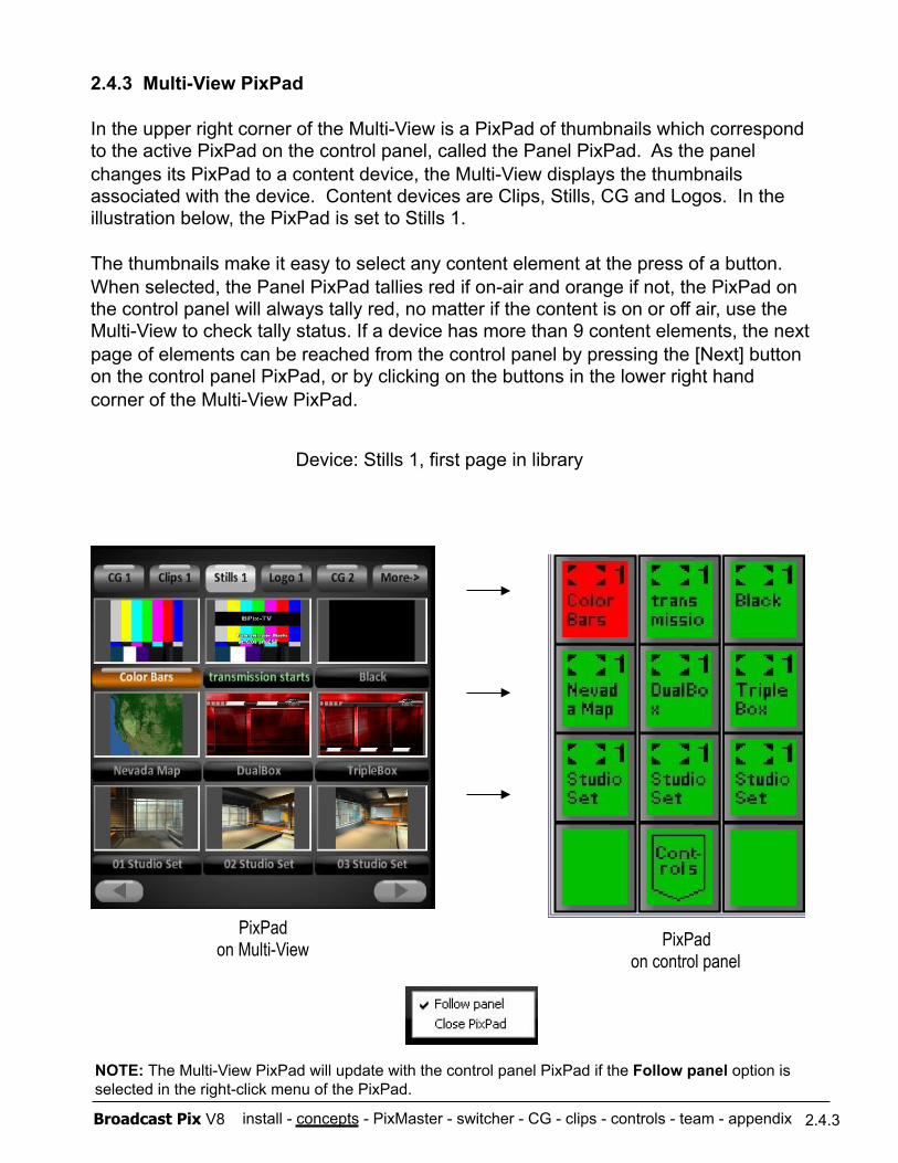
install - concepts - PixMaster - switcher - CG - clips - controls - team - appendix Broadcast Pix V8
2.4.3 Multi-View PixPad
In the upper right corner of the Multi-View is a PixPad of thumbnails which correspond to the active PixPad on the control panel, called the Panel PixPad. As the panel changes its PixPad to a content device, the Multi-View displays the thumbnails associated with the device. Content devices are Clips, Stills, CG and Logos. In the illustration below, the PixPad is set to Stills 1.
The thumbnails make it easy to select any content element at the press of a button. When selected, the Panel PixPad tallies red if on-air and orange if not, the PixPad on the control panel will always tally red, no matter if the content is on or off air, use the Multi-View to check tally status. If a device has more than 9 content elements, the next page of elements can be reached from the control panel by pressing the [Next] button on the control panel PixPad, or by clicking on the buttons in the lower right hand corner of the Multi-View PixPad.
PixPad on control panel
2.4.3
PixPad on Multi-View
Device: Stills 1, first page in library
NOTE: The Multi-View PixPad will update with the control panel PixPad if the Follow panel option is selected in the right-click menu of the PixPad.
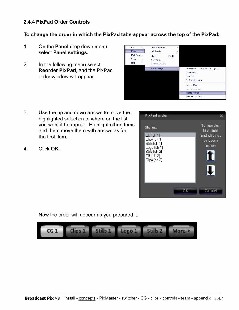
install - concepts - PixMaster - switcher - CG - clips - controls - team - appendix Broadcast Pix V8
To change the order in which the PixPad tabs appear across the top of the PixPad:
1. On the Panel drop down menu select Panel settings.
2. In the following menu select Reorder PixPad, and the PixPad order window will appear.
3. Use the up and down arrows to move the highlighted selection to where on the list you want it to appear. Highlight other items
and them move them with arrows as for the first item.
4. Click OK.
Now the order will appear as you prepared it.
2.4.4 PixPad Order Controls
2.4.4
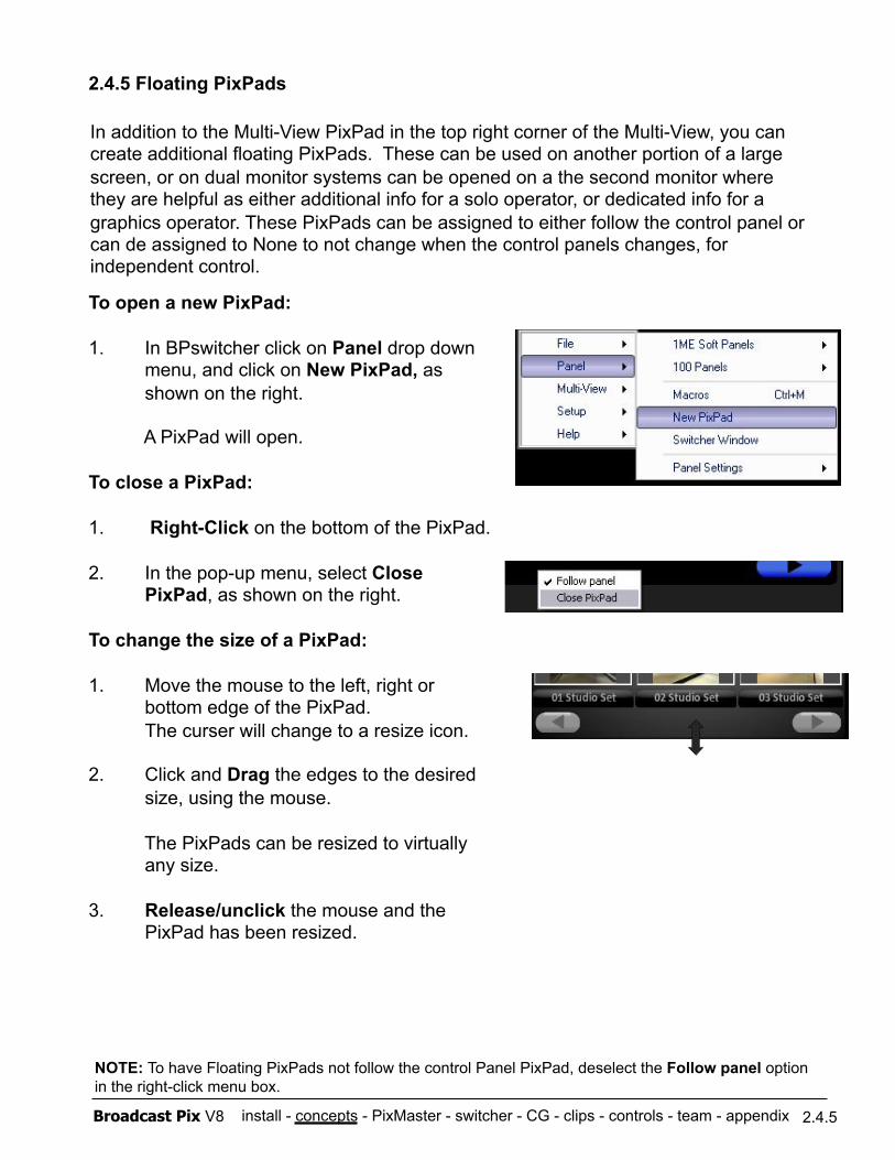
install - concepts - PixMaster - switcher - CG - clips - controls - team - appendix Broadcast Pix V8
To open a new PixPad:
1. In BPswitcher click on Panel drop down menu, and click on New PixPad, as shown on the right.
A PixPad will open.
To close a PixPad:
1. Right-Click on the bottom of the PixPad.
2. In the pop-up menu, select Close PixPad, as shown on the right.
To change the size of a PixPad:
1. Move the mouse to the left, right or bottom edge of the PixPad. The curser will change to a resize icon.
2. Click and Drag the edges to the desired size, using the mouse.
The PixPads can be resized to virtually any size.
3. Release/unclick the mouse and the PixPad has been resized.
2.4.5 Floating PixPads
In addition to the Multi-View PixPad in the top right corner of the Multi-View, you can create additional floating PixPads. These can be used on another portion of a large screen, or on dual monitor systems can be opened on a the second monitor where they are helpful as either additional info for a solo operator, or dedicated info for a graphics operator. These PixPads can be assigned to either follow the control panel or can de assigned to None to not change when the control panels changes, for independent control.
2.4.5
NOTE: To have Floating PixPads not follow the control Panel PixPad, deselect the Follow panel option in the right-click menu box.
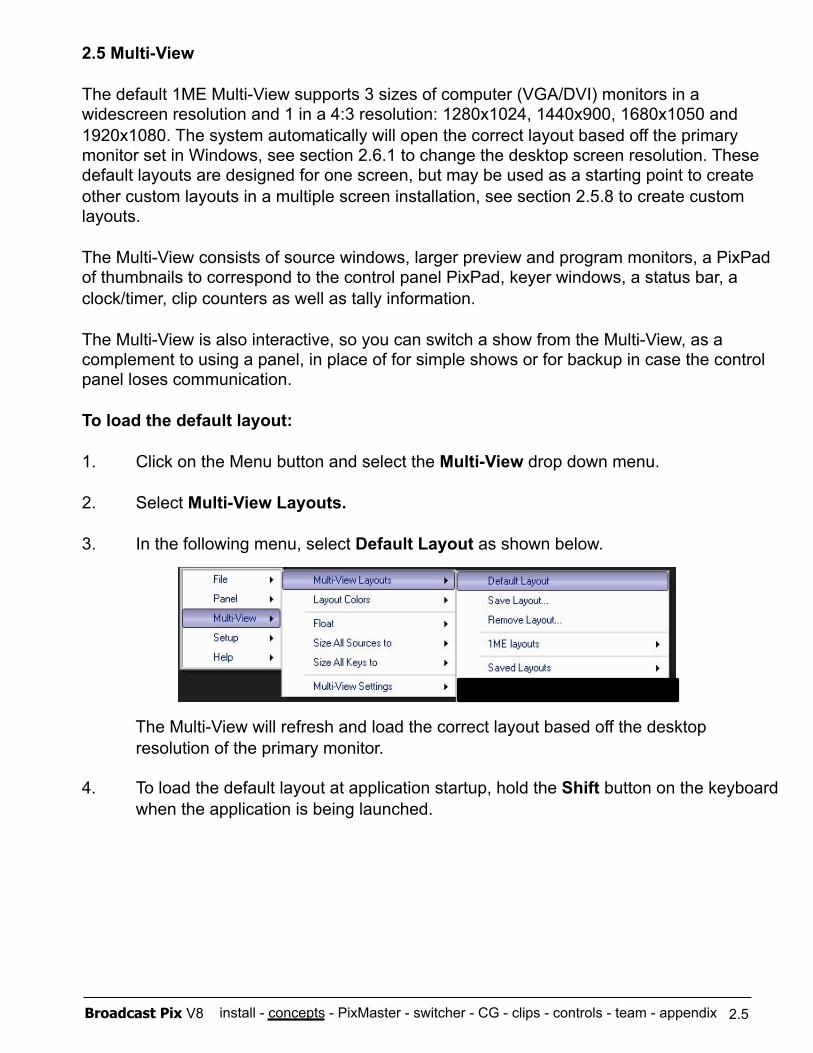
install - concepts - PixMaster - switcher - CG - clips - controls - team - appendix Broadcast Pix V8
2.5 Multi-View
The default 1ME Multi-View supports 3 sizes of computer (VGA/DVI) monitors in a widescreen resolution and 1 in a 4:3 resolution: 1280x1024, 1440x900, 1680x1050 and 1920x1080. The system automatically will open the correct layout based off the primary monitor set in Windows, see section 2.6.1 to change the desktop screen resolution. These default layouts are designed for one screen, but may be used as a starting point to create other custom layouts in a multiple screen installation, see section 2.5.8 to create custom layouts.
The Multi-View consists of source windows, larger preview and program monitors, a PixPad of thumbnails to correspond to the control panel PixPad, keyer windows, a status bar, a clock/timer, clip counters as well as tally information.
The Multi-View is also interactive, so you can switch a show from the Multi-View, as a complement to using a panel, in place of for simple shows or for backup in case the control panel loses communication.
To load the default layout:
1. Click on the Menu button and select the Multi-View drop down menu.
2. Select Multi-View Layouts.
3. In the following menu, select Default Layout as shown below.
The Multi-View will refresh and load the correct layout based off the desktop resolution of the primary monitor.
4. To load the default layout at application startup, hold the Shift button on the keyboard when the application is being launched.
2.5
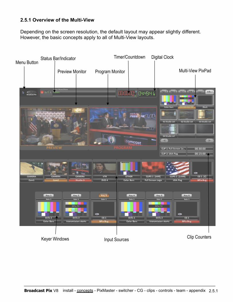
install - concepts - PixMaster - switcher - CG - clips - controls - team - appendix Broadcast Pix V8
2.5.1 Overview of the Multi-View
Depending on the screen resolution, the default layout may appear slightly different. However, the basic concepts apply to all of Multi-View layouts.
Multi-View PixPad
Keyer Windows
Preview Monitor Program Monitor
Input Sources Clip Counters
Status Bar/Indicator Digital Clock
2.5.1
Menu Button Timer/Countdown
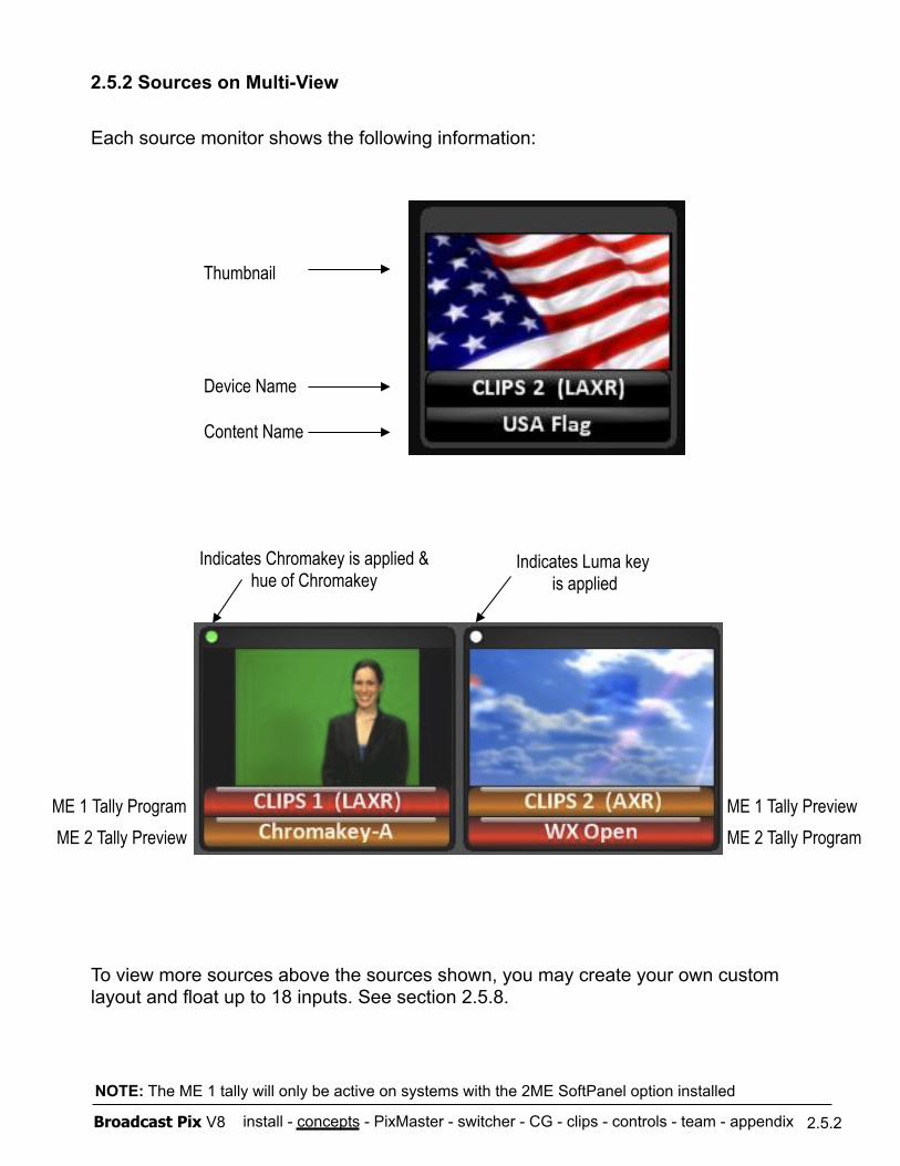
install - concepts - PixMaster - switcher - CG - clips - controls - team - appendix Broadcast Pix V8
Each source monitor shows the following information:
Thumbnail
Device Name
Content Name
To view more sources above the sources shown, you may create your own custom layout and float up to 18 inputs. See section 2.5.8.
2.5.2 Sources on Multi-View
2.5.2
ME 1 Tally Preview ME 2 Tally Program
ME 1 Tally Program ME 2 Tally Preview
Indicates Chromakey is applied & hue of Chromakey
Indicates Luma key is applied
NOTE: The ME 1 tally will only be active on systems with the 2ME SoftPanel option installed
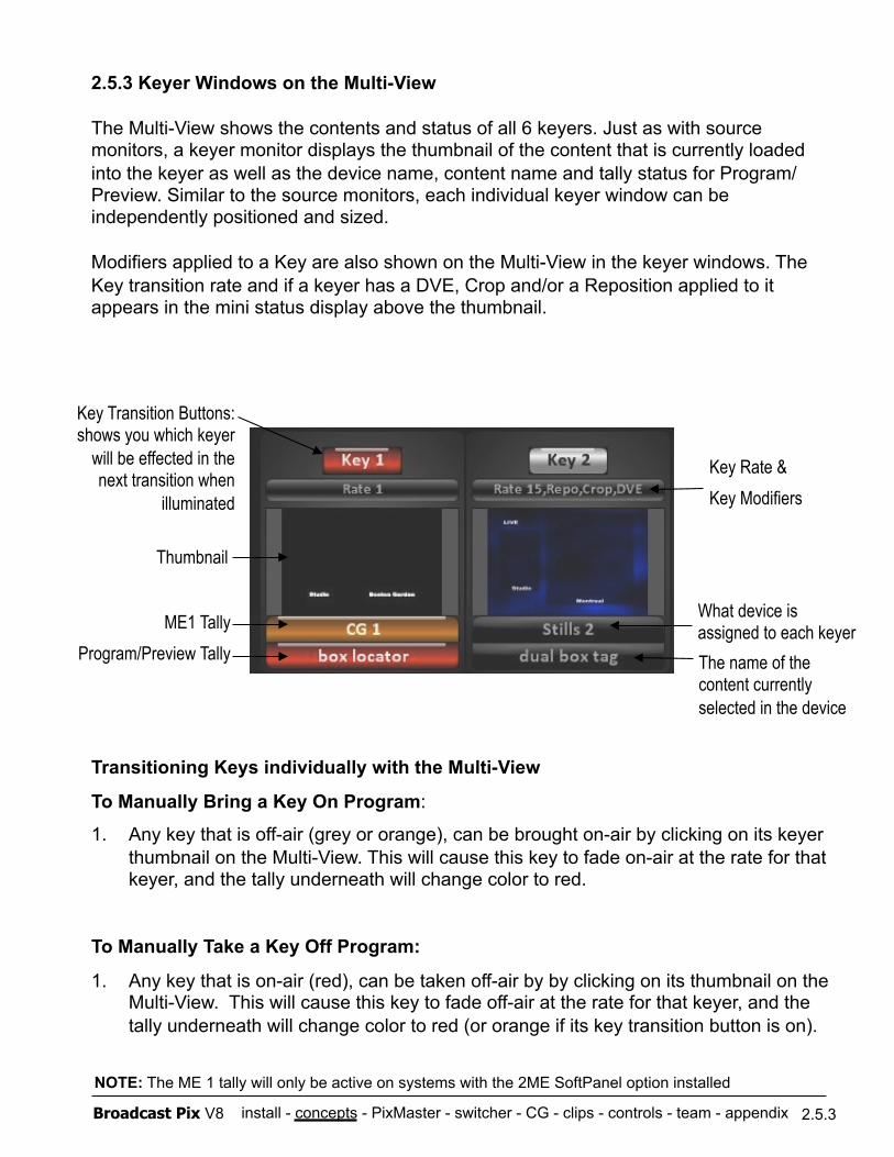
install - concepts - PixMaster - switcher - CG - clips - controls - team - appendix Broadcast Pix V8
2.5.3 Keyer Windows on the Multi-View
The Multi-View shows the contents and status of all 6 keyers. Just as with source monitors, a keyer monitor displays the thumbnail of the content that is currently loaded into the keyer as well as the device name, content name and tally status for Program/Preview. Similar to the source monitors, each individual keyer window can be independently positioned and sized.
Modifiers applied to a Key are also shown on the Multi-View in the keyer windows. The Key transition rate and if a keyer has a DVE, Crop and/or a Reposition applied to it appears in the mini status display above the thumbnail.
Transitioning Keys individually with the Multi-View
To Manually Bring a Key On Program:
1. Any key that is off-air (grey or orange), can be brought on-air by clicking on its keyer thumbnail on the Multi-View. This will cause this key to fade on-air at the rate for that keyer, and the tally underneath will change color to red.
To Manually Take a Key Off Program:
1. Any key that is on-air (red), can be taken off-air by by clicking on its thumbnail on the Multi-View. This will cause this key to fade off-air at the rate for that keyer, and the tally underneath will change color to red (or orange if its key transition button is on).
2.5.3
Key Transition Buttons: shows you which keyer
will be effected in the next transition when
illuminated
ME1 Tally Program/Preview Tally
What device is assigned to each keyer The name of the content currently selected in the device
Thumbnail
Key Rate & Key Modifiers
NOTE: The ME 1 tally will only be active on systems with the 2ME SoftPanel option installed
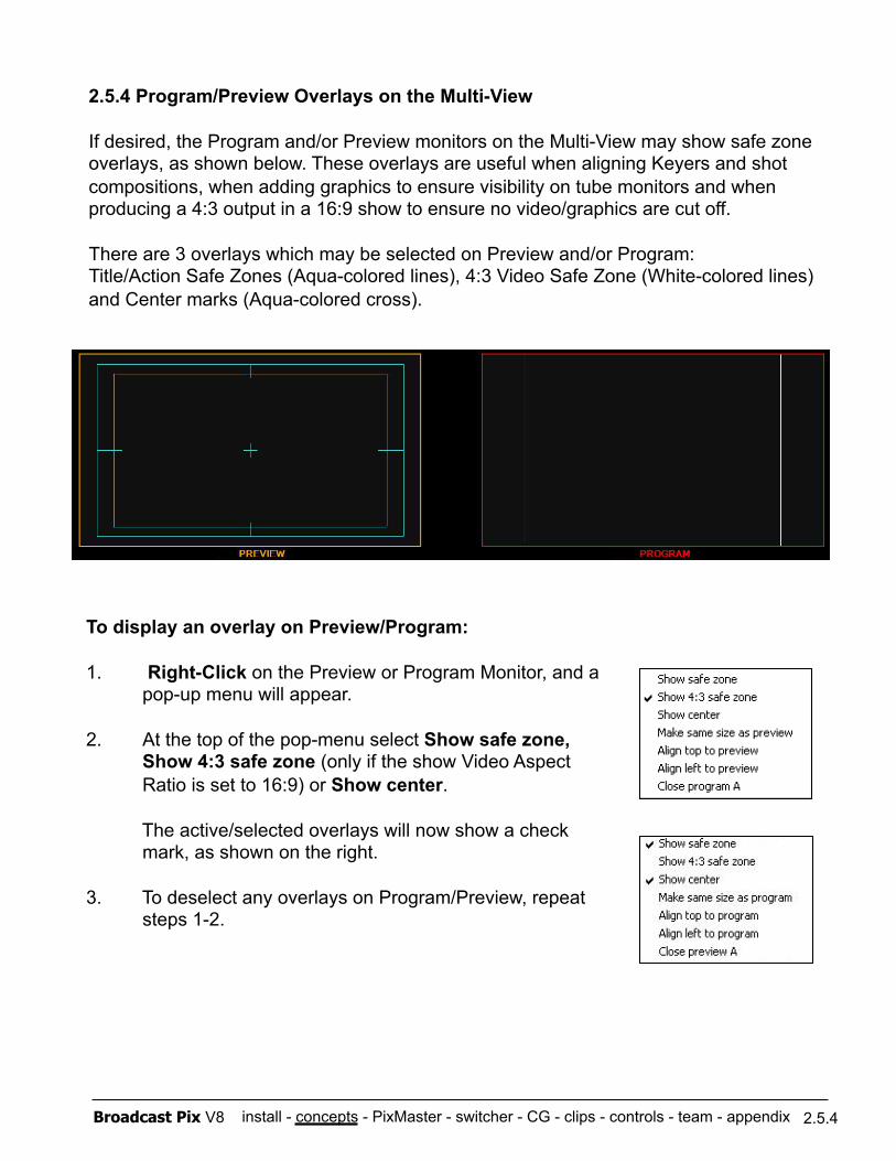
install - concepts - PixMaster - switcher - CG - clips - controls - team - appendix Broadcast Pix V8
2.5.4 Program/Preview Overlays on the Multi-View
If desired, the Program and/or Preview monitors on the Multi-View may show safe zone overlays, as shown below. These overlays are useful when aligning Keyers and shot compositions, when adding graphics to ensure visibility on tube monitors and when producing a 4:3 output in a 16:9 show to ensure no video/graphics are cut off.
There are 3 overlays which may be selected on Preview and/or Program: Title/Action Safe Zones (Aqua-colored lines), 4:3 Video Safe Zone (White-colored lines) and Center marks (Aqua-colored cross).
To display an overlay on Preview/Program:
1. Right-Click on the Preview or Program Monitor, and a pop-up menu will appear.
2. At the top of the pop-menu select Show safe zone, Show 4:3 safe zone (only if the show Video Aspect Ratio is set to 16:9) or Show center.
The active/selected overlays will now show a check mark, as shown on the right.
3. To deselect any overlays on Program/Preview, repeat steps 1-2.
2.5.4
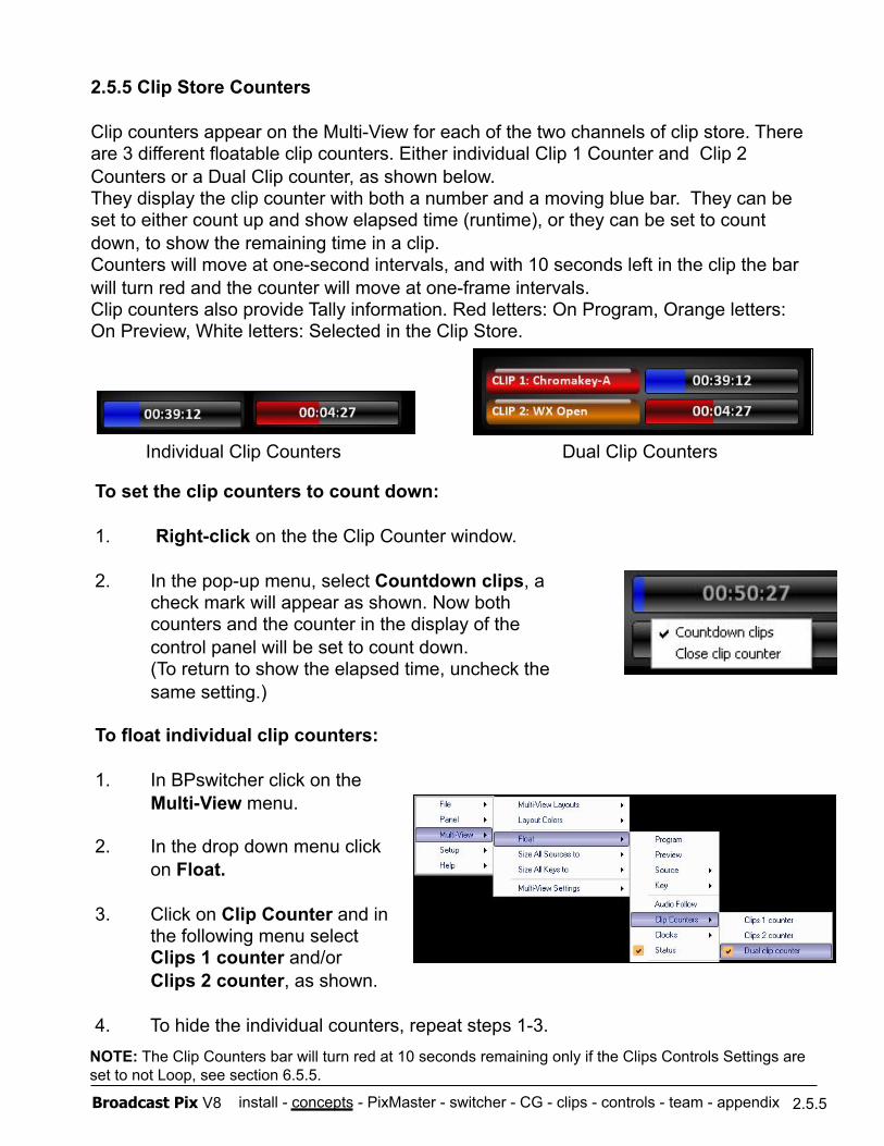
install - concepts - PixMaster - switcher - CG - clips - controls - team - appendix Broadcast Pix V8
2.5.5 Clip Store Counters
Clip counters appear on the Multi-View for each of the two channels of clip store. There are 3 different floatable clip counters. Either individual Clip 1 Counter and Clip 2 Counters or a Dual Clip counter, as shown below. They display the clip counter with both a number and a moving blue bar. They can be set to either count up and show elapsed time (runtime), or they can be set to count down, to show the remaining time in a clip. Counters will move at one-second intervals, and with 10 seconds left in the clip the bar will turn red and the counter will move at one-frame intervals. Clip counters also provide Tally information. Red letters: On Program, Orange letters: On Preview, White letters: Selected in the Clip Store.
To set the clip counters to count down:
1. Right-click on the the Clip Counter window.
2. In the pop-up menu, select Countdown clips, a check mark will appear as shown. Now both counters and the counter in the display of the control panel will be set to count down. (To return to show the elapsed time, uncheck the same setting.)
To float individual clip counters:
1. In BPswitcher click on the Multi-View menu.
2. In the drop down menu click on Float.
3. Click on Clip Counter and in the following menu select Clips 1 counter and/or Clips 2 counter, as shown.
4. To hide the individual counters, repeat steps 1-3.
2.5.5
NOTE: The Clip Counters bar will turn red at 10 seconds remaining only if the Clips Controls Settings are set to not Loop, see section 6.5.5.
Individual Clip Counters Dual Clip Counters
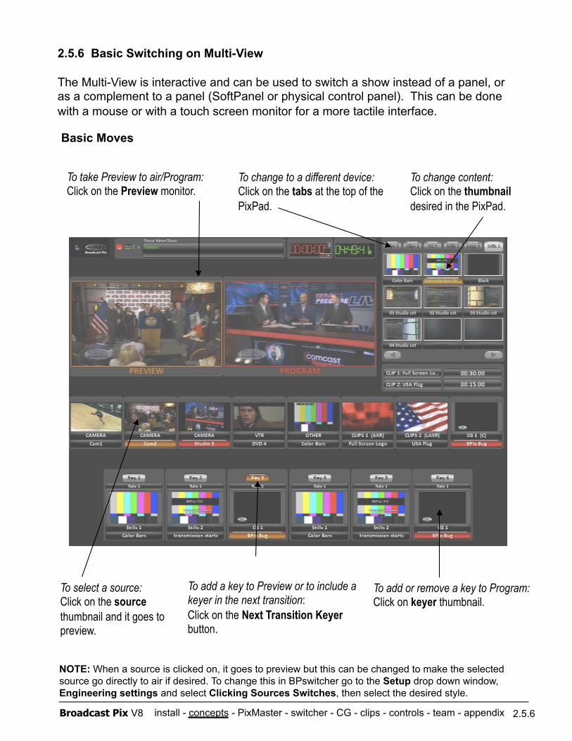
install - concepts - PixMaster - switcher - CG - clips - controls - team - appendix Broadcast Pix V8
2.5.6 Basic Switching on Multi-View
The Multi-View is interactive and can be used to switch a show instead of a panel, or as a complement to a panel (SoftPanel or physical control panel). This can be done with a mouse or with a touch screen monitor for a more tactile interface.
Basic Moves
2.5.6
NOTE: When a source is clicked on, it goes to preview but this can be changed to make the selected source go directly to air if desired. To change this in BPswitcher go to the Setup drop down window, Engineering settings and select Clicking Sources Switches, then select the desired style.
To change to a different device: Click on the tabs at the top of the PixPad.
To change content: Click on the thumbnail desired in the PixPad.
To take Preview to air/Program: Click on the Preview monitor.
To add a key to Preview or to include a keyer in the next transition: Click on the Next Transition Keyer button.
To select a source: Click on the source thumbnail and it goes to preview.
To add or remove a key to Program: Click on keyer thumbnail.

install - concepts - PixMaster - switcher - CG - clips - controls - team - appendix Broadcast Pix V8
2.5.7 Advanced Switching on Multi-View
You can access even more switching capabilities on the Multi-View by floating the Switcher Window, as described in section in 2.5.8. These switcher controls work exactly the same as on the control panel. For more switcher controls beyond these, like to change key and transition rates or effects, open a SoftPanel from the Panel, Soft Panel drop down menu.
To float the Switcher Window:
1. In BPswitcher select the Panel drop down menu.
2. Select Switcher window, as shown on the right.
Advanced Switching:
2.5.7
To assign a source to a keyer: Click on one of the Key Assignment buttons, then click on the thumbnail of the source you wish to assign, and its key thumbnail will change to show the new key source.
To add keys or background video to the next transition: Click on the Key or BGR buttons, and each will illuminate as you click on it and the keyed image will be added to the preview monitor if it is not already on air. The button illuminates red when the key is on air, and orange when it is on preview.
To change the style of transition that occurs when you click on the Preview monitor: Click on Cut, Mix or Wipe.
To take Preview to air/Program Click on the Cut or Auto above (Auto executes whichever transition style and rate is selected).
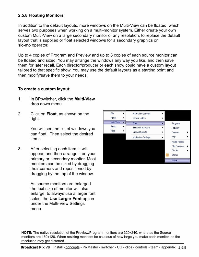
install - concepts - PixMaster - switcher - CG - clips - controls - team - appendix Broadcast Pix V8
2.5.8 Floating Monitors
In addition to the default layouts, more windows on the Multi-View can be floated, which serves two purposes when working on a multi-monitor system. Either create your own custom Multi-View on a large secondary monitor of any resolution, to replace the default layout that is supplied or float selected windows for a secondary graphics or slo-mo operator.
Up to 4 copies of Program and Preview and up to 3 copies of each source monitor can be floated and sized. You may arrange the windows any way you like, and then save them for later recall. Each director/producer or each show could have a custom layout tailored to that specific show. You may use the default layouts as a starting point and then modify/save them to your needs.
To create a custom layout:
1. In BPswitcher, click the Multi-View drop down menu.
2. Click on Float, as shown on the right.
You will see the list of windows you can float. Then select the desired items.
3. After selecting each item, it will appear, and then arrange it on your primary or secondary monitor. Most monitors can be sized by dragging their corners and repositioned by dragging by the top of the window.
As source monitors are enlarged the text size of monitor will also enlarge, to always use a larger font select the Use Larger Font option under the Multi-View Settings menu.
2.5.8
NOTE: The native resolution of the Preview/Program monitors are 320x240, where as the Source monitors are 180x120. When resizing monitors be cautious of how large you make each monitor, as the resolution may get distorted.
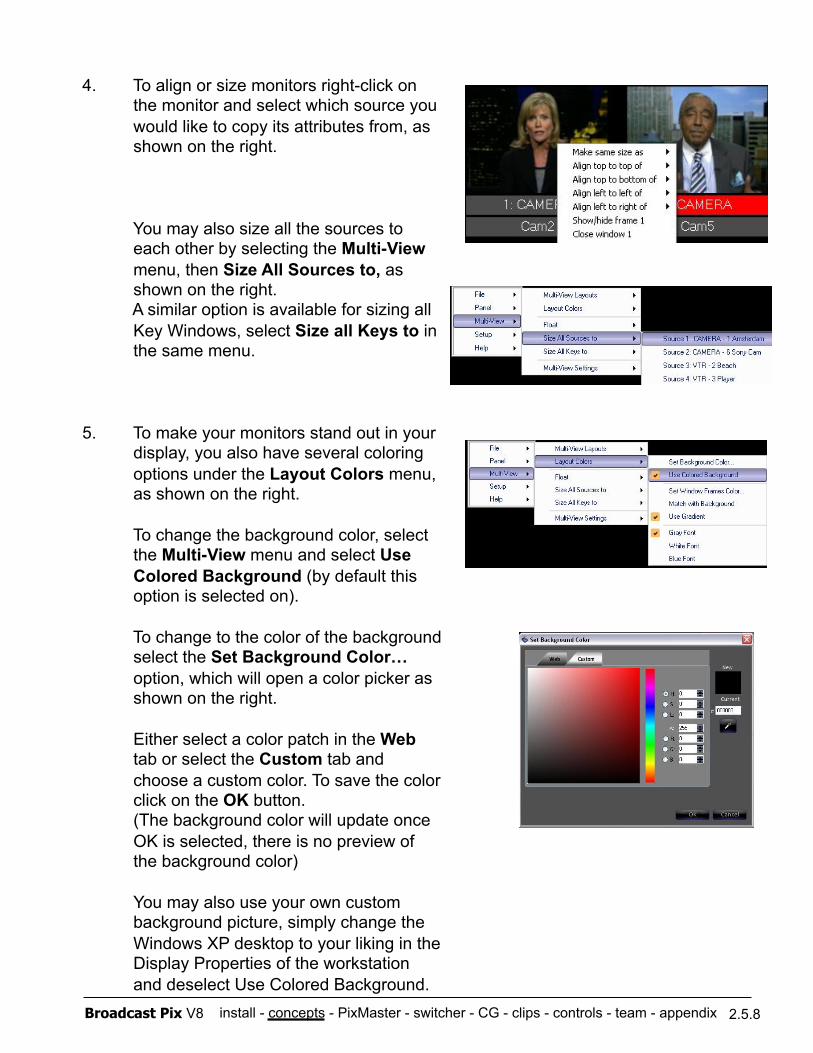
install - concepts - PixMaster - switcher - CG - clips - controls - team - appendix Broadcast Pix V8
4. To align or size monitors right-click on the monitor and select which source you would like to copy its attributes from, as shown on the right.
You may also size all the sources to each other by selecting the Multi-View menu, then Size All Sources to, as shown on the right. A similar option is available for sizing all Key Windows, select Size all Keys to in the same menu.
5. To make your monitors stand out in your display, you also have several coloring options under the Layout Colors menu, as shown on the right.
To change the background color, select the Multi-View menu and select Use Colored Background (by default this option is selected on).
To change to the color of the background select the Set Background Color… option, which will open a color picker as shown on the right.
Either select a color patch in the Web tab or select the Custom tab and choose a custom color. To save the color click on the OK button. (The background color will update once OK is selected, there is no preview of the background color)
You may also use your own custom background picture, simply change the Windows XP desktop to your liking in the Display Properties of the workstation and deselect Use Colored Background.
2.5.8
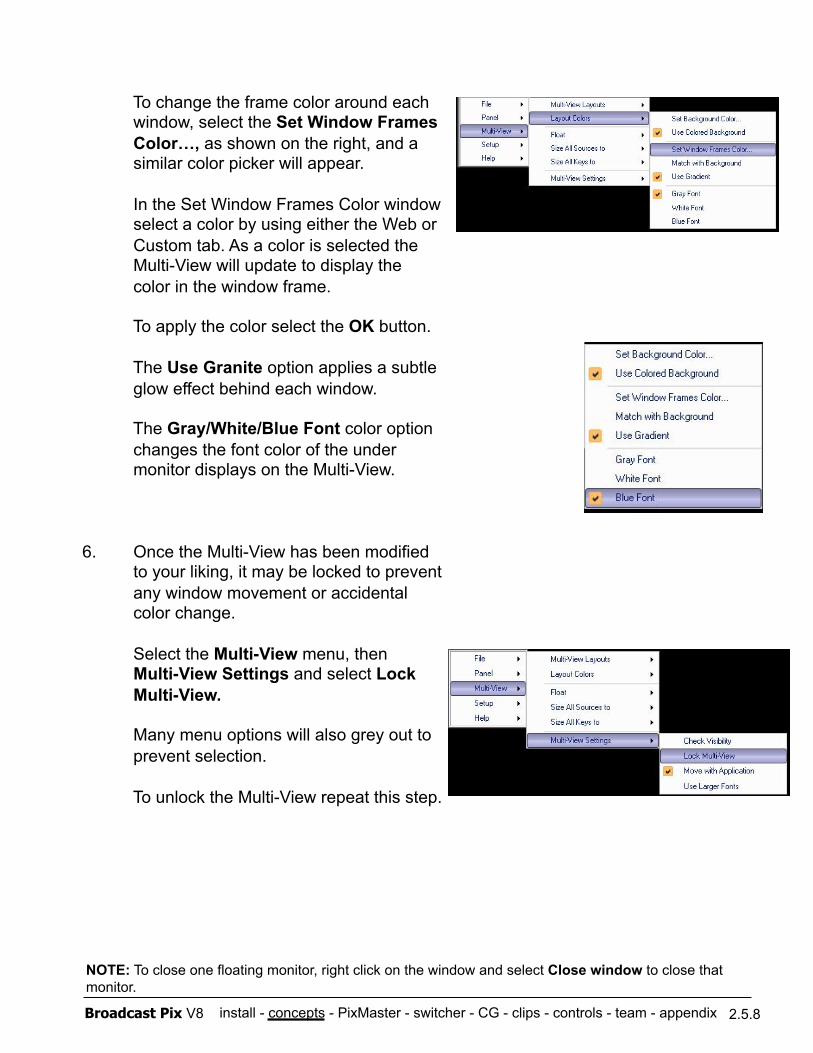
install - concepts - PixMaster - switcher - CG - clips - controls - team - appendix Broadcast Pix V8
To change the frame color around each window, select the Set Window Frames Color…, as shown on the right, and a similar color picker will appear.
In the Set Window Frames Color window select a color by using either the Web or Custom tab. As a color is selected the Multi-View will update to display the color in the window frame.
To apply the color select the OK button.
The Use Granite option applies a subtle glow effect behind each window.
The Gray/White/Blue Font color option changes the font color of the under monitor displays on the Multi-View.
6. Once the Multi-View has been modified to your liking, it may be locked to prevent any window movement or accidental color change.
Select the Multi-View menu, then Multi-View Settings and select Lock Multi-View.
Many menu options will also grey out to prevent selection.
To unlock the Multi-View repeat this step.
2.5.8
NOTE: To close one floating monitor, right click on the window and select Close window to close that monitor.
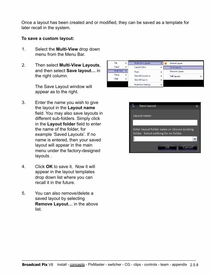
install - concepts - PixMaster - switcher - CG - clips - controls - team - appendix Broadcast Pix V8
Once a layout has been created and or modified, they can be saved as a template for later recall in the system.
To save a custom layout:
2.5.8
1. Select the Multi-View drop down menu from the Menu Bar.
2. Then select Multi-View Layouts, and then select Save layout… in the right column.
The Save Layout window will appear as to the right.
3. Enter the name you wish to give the layout in the Layout name field. You may also save layouts in different sub-folders. Simply click in the Layout folder field to enter the name of the folder, for example ‘Saved Layouts’. If no name is entered, then your saved layout will appear in the main menu under the factory-designed layouts .
4. Click OK to save it. Now it will appear in the layout templates drop down list where you can recall it in the future.
5. You can also remove/delete a saved layout by selecting Remove Layout… in the above list.
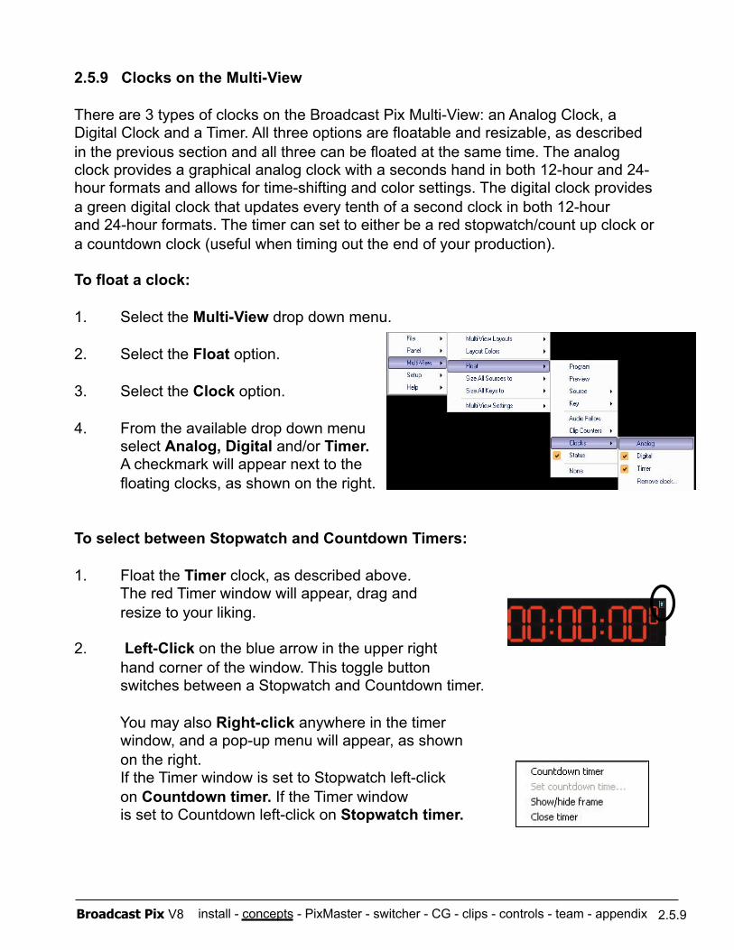
install - concepts - PixMaster - switcher - CG - clips - controls - team - appendix Broadcast Pix V8
2.5.9 Clocks on the Multi-View
There are 3 types of clocks on the Broadcast Pix Multi-View: an Analog Clock, a Digital Clock and a Timer. All three options are floatable and resizable, as described in the previous section and all three can be floated at the same time. The analog clock provides a graphical analog clock with a seconds hand in both 12-hour and 24- hour formats and allows for time-shifting and color settings. The digital clock provides a green digital clock that updates every tenth of a second clock in both 12-hour and 24-hour formats. The timer can set to either be a red stopwatch/count up clock or a countdown clock (useful when timing out the end of your production).
To float a clock:
1. Select the Multi-View drop down menu.
2. Select the Float option.
3. Select the Clock option.
4. From the available drop down menu select Analog, Digital and/or Timer. A checkmark will appear next to the floating clocks, as shown on the right.
To select between Stopwatch and Countdown Timers:
1. Float the Timer clock, as described above. The red Timer window will appear, drag and resize to your liking.
2. Left-Click on the blue arrow in the upper right hand corner of the window. This toggle button switches between a Stopwatch and Countdown timer.
You may also Right-click anywhere in the timer window, and a pop-up menu will appear, as shown on the right. If the Timer window is set to Stopwatch left-click
on Countdown timer. If the Timer window is set to Countdown left-click on Stopwatch timer.
2.5.9
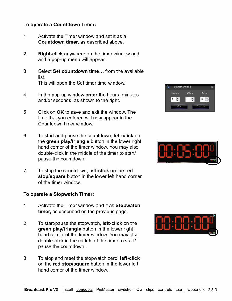
install - concepts - PixMaster - switcher - CG - clips - controls - team - appendix Broadcast Pix V8
To operate a Countdown Timer:
1. Activate the Timer window and set it as a Countdown timer, as described above.
2. Right-click anywhere on the timer window and and a pop-up menu will appear.
3. Select Set countdown time… from the available list. This will open the Set timer time window.
4. In the pop-up window enter the hours, minutes and/or seconds, as shown to the right.
5. Click on OK to save and exit the window. The time that you entered will now appear in the Countdown timer window.
6. To start and pause the countdown, left-click on the green play/triangle button in the lower right hand corner of the timer window. You may also double-click in the middle of the timer to start/pause the countdown.
7. To stop the countdown, left-click on the red stop/square button in the lower left hand corner of the timer window.
To operate a Stopwatch Timer:
1. Activate the Timer window and it as Stopwatch timer, as described on the previous page.
2. To start/pause the stopwatch, left-click on the green play/triangle button in the lower right hand corner of the timer window. You may also double-click in the middle of the timer to start/pause the countdown.
3. To stop and reset the stopwatch zero, left-click on the red stop/square button in the lower left hand corner of the timer window.
2.5.9
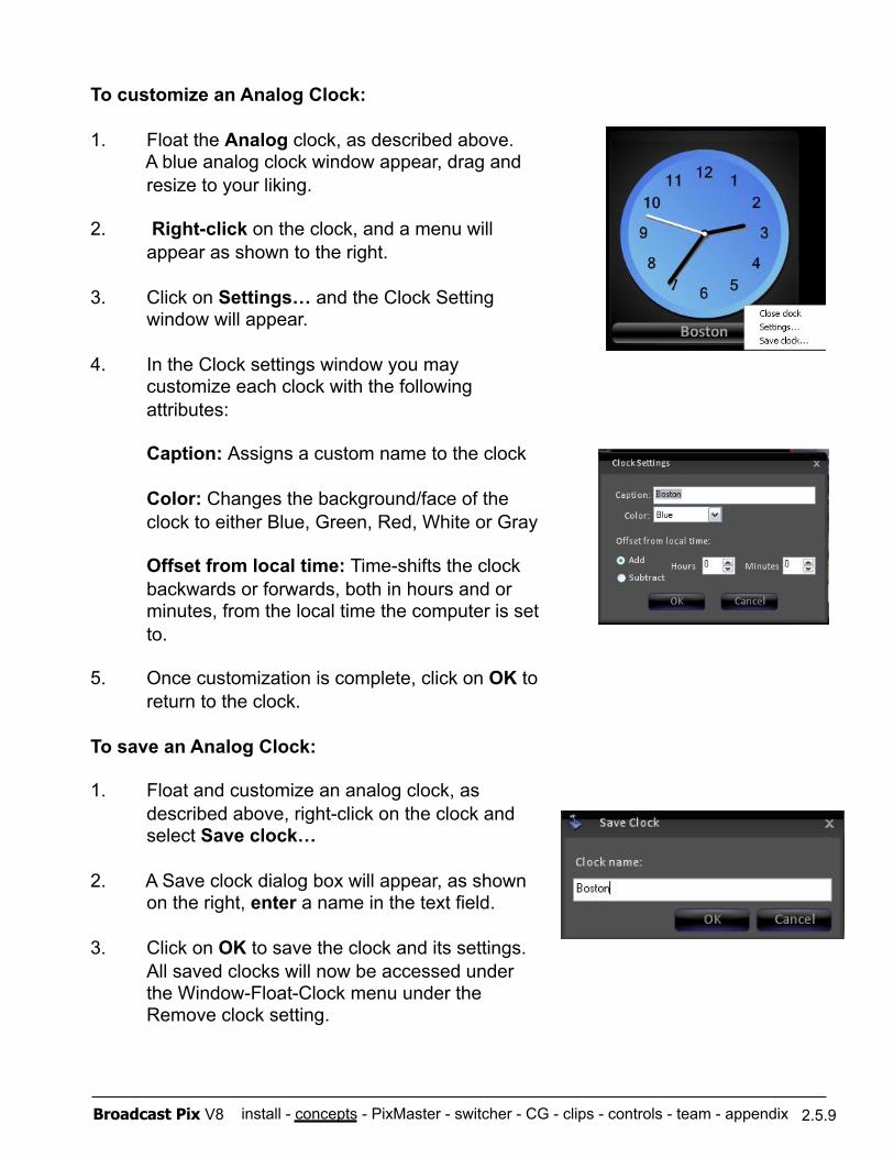
install - concepts - PixMaster - switcher - CG - clips - controls - team - appendix Broadcast Pix V8
To customize an Analog Clock:
1. Float the Analog clock, as described above. A blue analog clock window appear, drag and resize to your liking.
2. Right-click on the clock, and a menu will appear as shown to the right.
3. Click on Settings… and the Clock Setting window will appear.
4. In the Clock settings window you may customize each clock with the following attributes:
Caption: Assigns a custom name to the clock
Color: Changes the background/face of the clock to either Blue, Green, Red, White or Gray
Offset from local time: Time-shifts the clock backwards or forwards, both in hours and or minutes, from the local time the computer is set to.
5. Once customization is complete, click on OK to return to the clock.
To save an Analog Clock:
1. Float and customize an analog clock, as described above, right-click on the clock and select Save clock…
2. A Save clock dialog box will appear, as shown on the right, enter a name in the text field.
3. Click on OK to save the clock and its settings. All saved clocks will now be accessed under the Window-Float-Clock menu under the Remove clock setting.
2.5.9
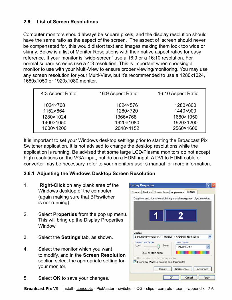
install - concepts - PixMaster - switcher - CG - clips - controls - team - appendix Broadcast Pix V8
It is important to set your Windows desktop settings prior to starting the Broadcast Pix Switcher application. It is not advised to change the desktop resolutions while the application is running. Be advised that some large LCD/Plasma monitors do not accept high resolutions on the VGA input, but do on a HDMI input. A DVI to HDMI cable or converter may be necessary, refer to your monitors user’s manual for more information.
2.6.1 Adjusting the Windows Desktop Screen Resolution
1. Right-Click on any blank area of the Windows desktop of the computer (again making sure that BPswitcher is not running).
2. Select Properties from the pop up menu. This will bring up the Display Properties Window.
3. Select the Settings tab, as shown.
4. Select the monitor which you want to modify, and in the Screen Resolution section select the appropriate setting for your monitor.
5. Select OK to save your changes.
2.6 List of Screen Resolutions
Computer monitors should always be square pixels, and the display resolution should have the same ratio as the aspect of the screen. The aspect of screen should never be compensated for, this would distort text and images making them look too wide or skinny. Below is a list of Monitor Resolutions with their native aspect ratios for easy reference. If your monitor is “wide-screen” use a 16:9 or a 16:10 resolution. For normal square screens use a 4:3 resolution. This is important when choosing a monitor to use with your Multi-View to ensure proper viewing/monitoring. You may use any screen resolution for your Multi-View, but it’s recommended to use a 1280x1024, 1680x1050 or 1920x1080 monitor.
4:3 Aspect Ratio 16:9 Aspect Ratio 16:10 Aspect Ratio
1024×768 1024×576 1280×800 1152×864 1280×720 1440×900
1280×1024 1366×768 1680×1050 1400×1050 1920×1080 1920×1200 1600×1200 2048×1152 2560×1600
2.6
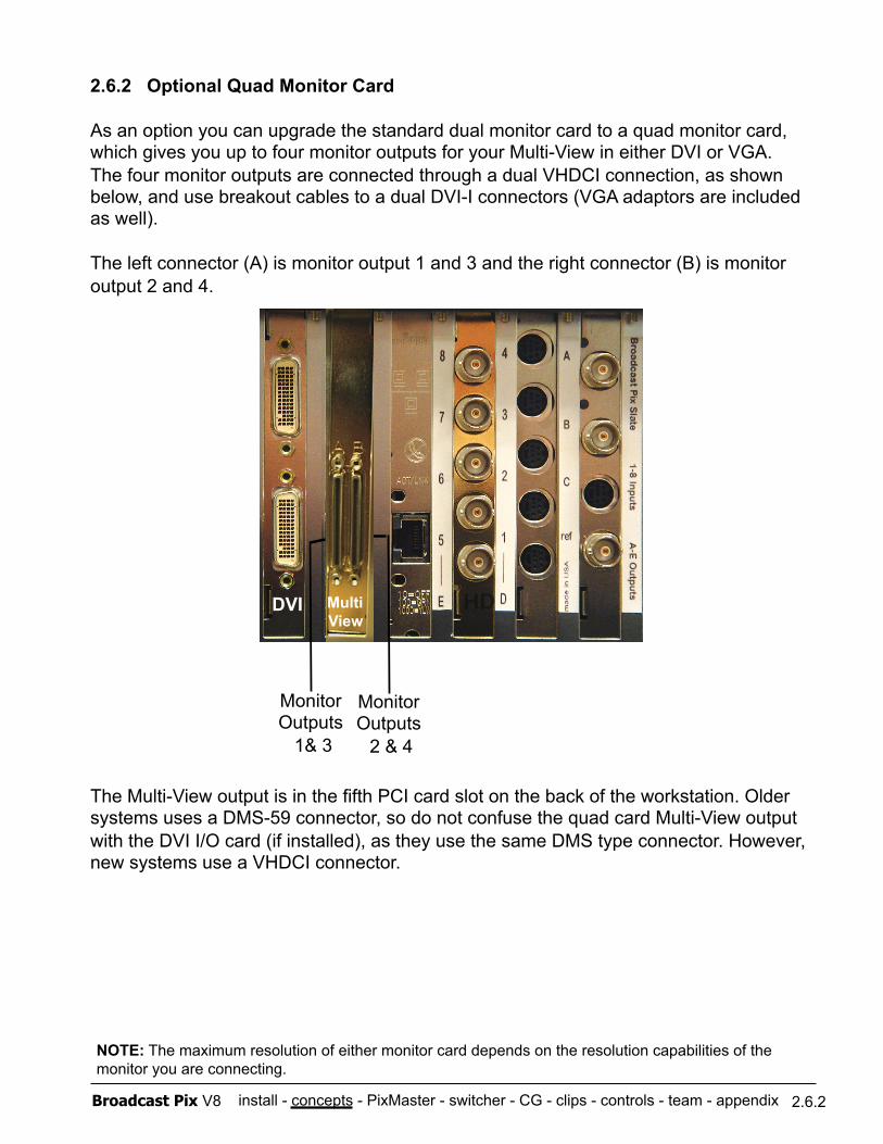
install - concepts - PixMaster - switcher - CG - clips - controls - team - appendix Broadcast Pix V8
2.6.2 Optional Quad Monitor Card
As an option you can upgrade the standard dual monitor card to a quad monitor card, which gives you up to four monitor outputs for your Multi-View in either DVI or VGA. The four monitor outputs are connected through a dual VHDCI connection, as shown below, and use breakout cables to a dual DVI-I connectors (VGA adaptors are included as well).
The left connector (A) is monitor output 1 and 3 and the right connector (B) is monitor output 2 and 4.
The Multi-View output is in the fifth PCI card slot on the back of the workstation. Older systems uses a DMS-59 connector, so do not confuse the quad card Multi-View output with the DVI I/O card (if installed), as they use the same DMS type connector. However, new systems use a VHDCI connector.
2.6.2
NOTE: The maximum resolution of either monitor card depends on the resolution capabilities of the monitor you are connecting.
DVI
Monitor Outputs
1& 3
Monitor Outputs 2 & 4
Multi View
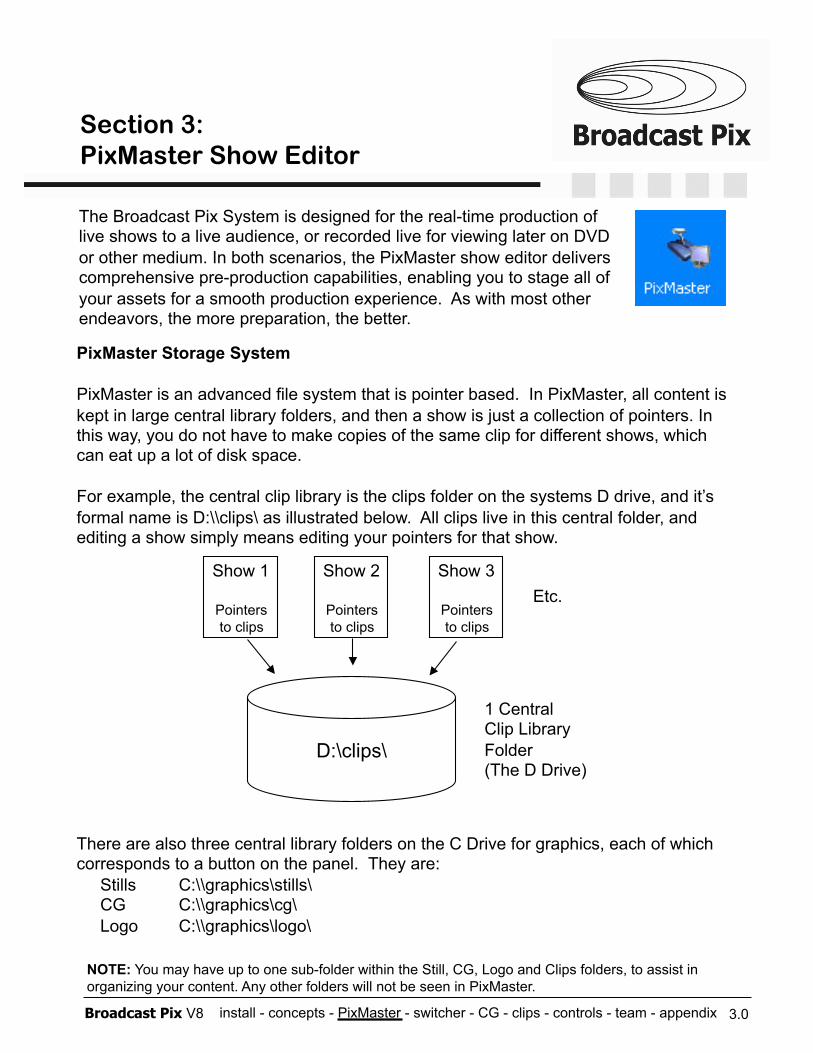
install - concepts - PixMaster - switcher - CG - clips - controls - team - appendix Broadcast Pix V8
PixMaster Storage System
PixMaster is an advanced file system that is pointer based. In PixMaster, all content is kept in large central library folders, and then a show is just a collection of pointers. In this way, you do not have to make copies of the same clip for different shows, which can eat up a lot of disk space.
For example, the central clip library is the clips folder on the systems D drive, and it’s formal name is D:\\clips\ as illustrated below. All clips live in this central folder, and editing a show simply means editing your pointers for that show.
There are also three central library folders on the C Drive for graphics, each of which corresponds to a button on the panel. They are: Stills C:\\graphics\stills\ CG C:\\graphics\cg\ Logo C:\\graphics\logo\
3.0
D:\clips\
Show 1
Pointers to clips
Show 2
Pointers to clips
Show 3
Pointers to clips
Etc.
1 Central Clip Library Folder (The D Drive)
The Broadcast Pix System is designed for the real-time production of live shows to a live audience, or recorded live for viewing later on DVD or other medium. In both scenarios, the PixMaster show editor delivers comprehensive pre-production capabilities, enabling you to stage all of your assets for a smooth production experience. As with most other endeavors, the more preparation, the better.
NOTE: You may have up to one sub-folder within the Still, CG, Logo and Clips folders, to assist in organizing your content. Any other folders will not be seen in PixMaster.
Section 3: PixMaster Show Editor
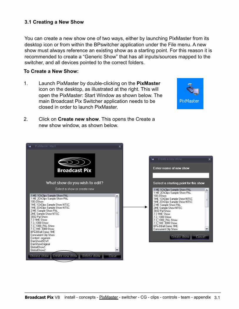
install - concepts - PixMaster - switcher - CG - clips - controls - team - appendix Broadcast Pix V8
You can create a new show one of two ways, either by launching PixMaster from its desktop icon or from within the BPswitcher application under the File menu. A new show must always reference an existing show as a starting point. For this reason it is recommended to create a “Generic Show” that has all inputs/sources mapped to the switcher, and all devices pointed to the correct folders.
3.1
To Create a New Show:
1. Launch PixMaster by double-clicking on the PixMaster icon on the desktop, as illustrated at the right. This will open the PixMaster: Start Window as shown below. The main Broadcast Pix Switcher application needs to be closed in order to launch PixMaster.
2. Click on Create new show. This opens the Create a new show window, as shown below.
3.1 Creating a New Show
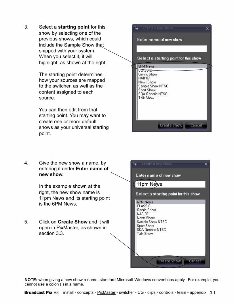
install - concepts - PixMaster - switcher - CG - clips - controls - team - appendix Broadcast Pix V8 3.1
3. Select a starting point for this show by selecting one of the previous shows, which could include the Sample Show that shipped with your system. When you select it, it will highlight, as shown at the right.
The starting point determines how your sources are mapped to the switcher, as well as the content assigned to each source.
You can then edit from that starting point. You may want to create one or more default shows as your universal starting point.
4. Give the new show a name, by entering it under Enter name of new show.
In the example shown at the right, the new show name is 11pm News and its starting point is the 6PM News.
5. Click on Create Show and it will open in PixMaster, as shown in section 3.3.
NOTE: when giving a new show a name, standard Microsoft Windows conventions apply. For example, you cannot use a colon (:) in a name.
11pm News
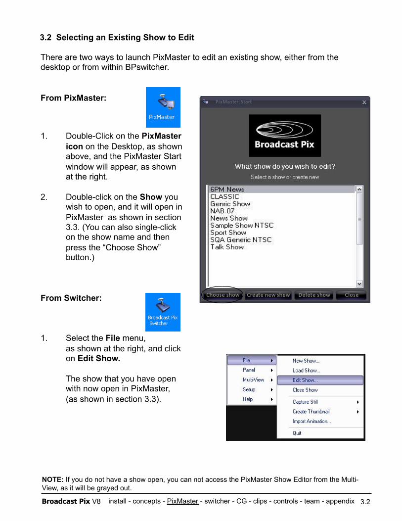
install - concepts - PixMaster - switcher - CG - clips - controls - team - appendix Broadcast Pix V8
1. Double-Click on the PixMaster icon on the Desktop, as shown above, and the PixMaster Start window will appear, as shown at the right.
2. Double-click on the Show you wish to open, and it will open in PixMaster as shown in section 3.3. (You can also single-click on the show name and then press the “Choose Show” button.)
From Switcher:
1. Select the File menu, as shown at the right, and click on Edit Show.
The show that you have open with now open in PixMaster, (as shown in section 3.3).
3.2
3.2 Selecting an Existing Show to Edit
There are two ways to launch PixMaster to edit an existing show, either from the desktop or from within BPswitcher.
From PixMaster:
NOTE: If you do not have a show open, you can not access the PixMaster Show Editor from the Multi-View, as it will be grayed out.
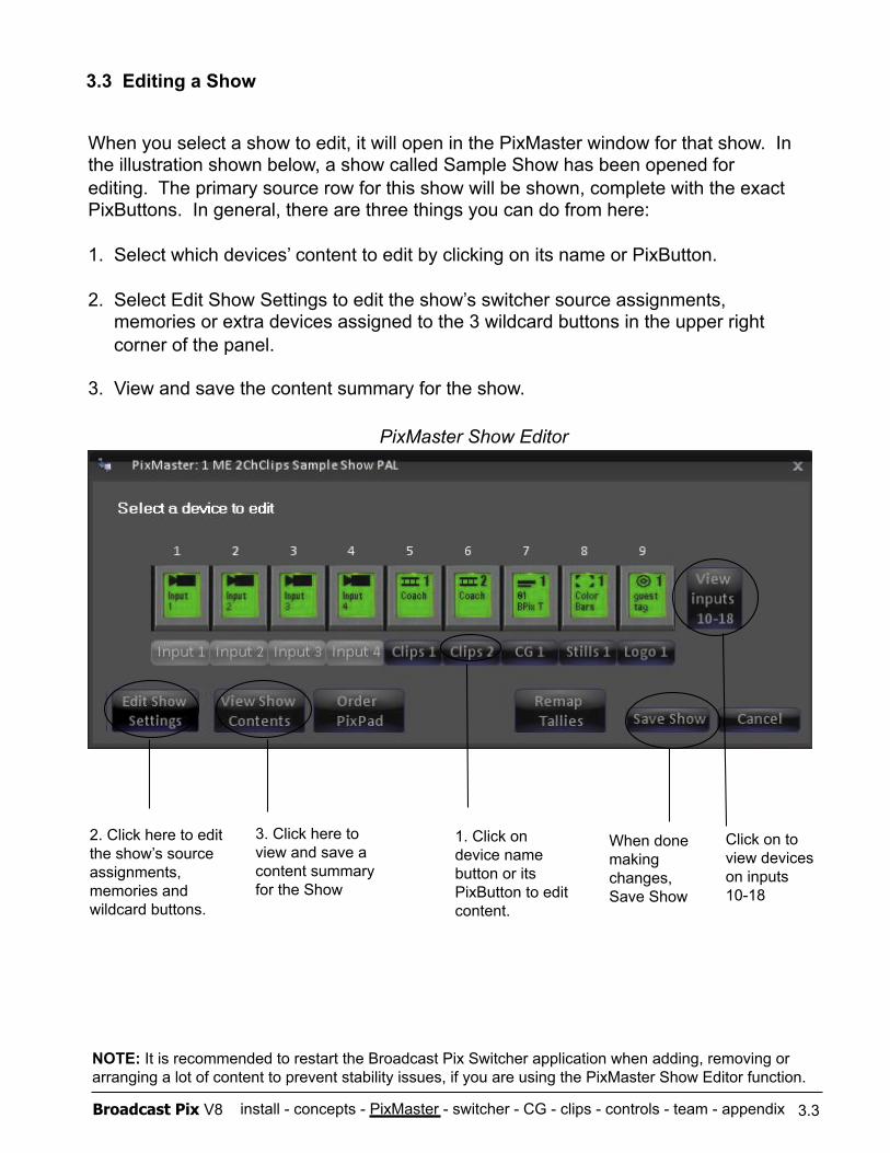
install - concepts - PixMaster - switcher - CG - clips - controls - team - appendix Broadcast Pix V8 3.3
3.3 Editing a Show
When you select a show to edit, it will open in the PixMaster window for that show. In the illustration shown below, a show called Sample Show has been opened for editing. The primary source row for this show will be shown, complete with the exact PixButtons. In general, there are three things you can do from here:
1. Select which devices’ content to edit by clicking on its name or PixButton.
2. Select Edit Show Settings to edit the show’s switcher source assignments, memories or extra devices assigned to the 3 wildcard buttons in the upper right corner of the panel.
3. View and save the content summary for the show.
PixMaster Show Editor
1. Click on device name button or its PixButton to edit content.
2. Click here to edit the show’s source assignments, memories and wildcard buttons.
3. Click here to view and save a content summary for the Show
When done making changes, Save Show
NOTE: It is recommended to restart the Broadcast Pix Switcher application when adding, removing or arranging a lot of content to prevent stability issues, if you are using the PixMaster Show Editor function.
Click on to view devices on inputs 10-18
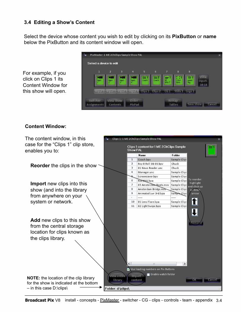
install - concepts - PixMaster - switcher - CG - clips - controls - team - appendix Broadcast Pix V8
3.4 Editing a Show’s Content
3.4
Select the device whose content you wish to edit by clicking on its PixButton or name below the PixButton and its content window will open.
For example, if you click on Clips 1 its Content Window for this show will open.
Content Window:
The content window, in this case for the “Clips 1” clip store, enables you to:
Reorder the clips in the show
Import new clips into this show (and into the library from anywhere on your system or network.
Add new clips to this show from the central storage location for clips known as the clips library.
NOTE: the location of the clip library for the show is indicated at the bottom – in this case D:\clips\
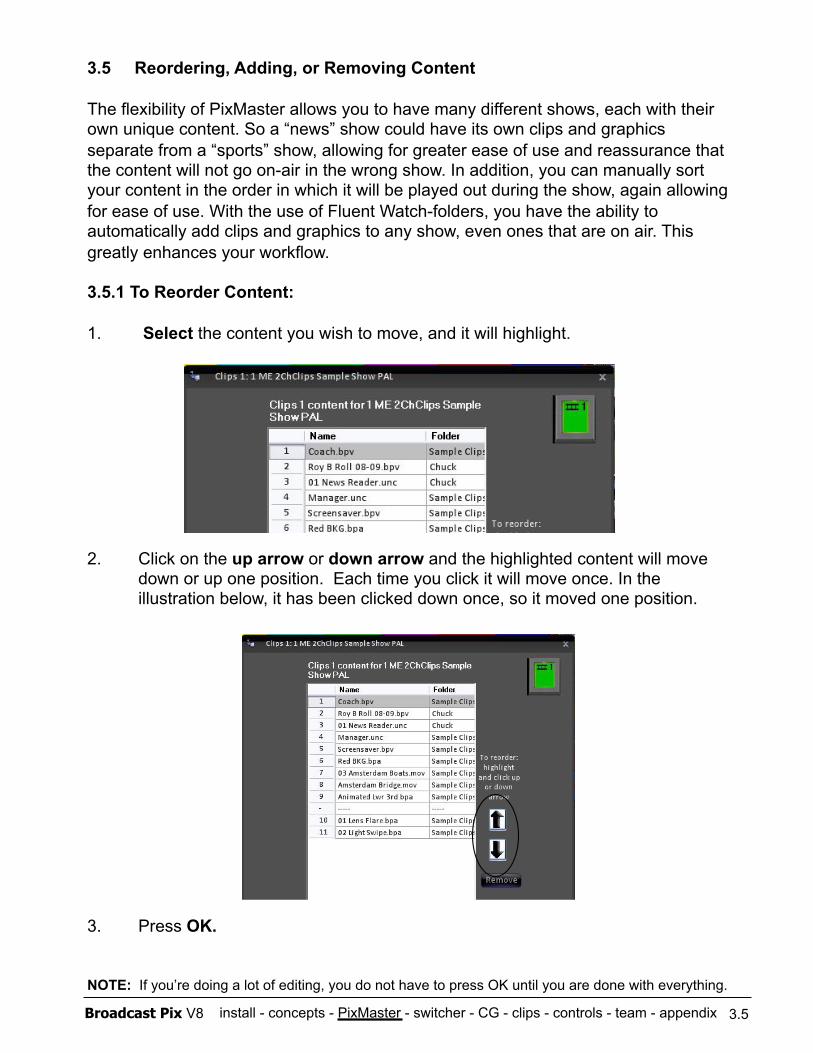
install - concepts - PixMaster - switcher - CG - clips - controls - team - appendix Broadcast Pix V8
3.5 Reordering, Adding, or Removing Content
The flexibility of PixMaster allows you to have many different shows, each with their own unique content. So a “news” show could have its own clips and graphics separate from a “sports” show, allowing for greater ease of use and reassurance that the content will not go on-air in the wrong show. In addition, you can manually sort your content in the order in which it will be played out during the show, again allowing for ease of use. With the use of Fluent Watch-folders, you have the ability to automatically add clips and graphics to any show, even ones that are on air. This greatly enhances your workflow.
3.5.1 To Reorder Content:
1. Select the content you wish to move, and it will highlight.
2. Click on the up arrow or down arrow and the highlighted content will move down or up one position. Each time you click it will move once. In the illustration below, it has been clicked down once, so it moved one position.
3. Press OK.
NOTE: If you’re doing a lot of editing, you do not have to press OK until you are done with everything.
3.5
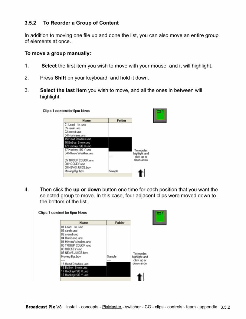
install - concepts - PixMaster - switcher - CG - clips - controls - team - appendix Broadcast Pix V8
To move a group manually:
1. Select the first item you wish to move with your mouse, and it will highlight.
2. Press Shift on your keyboard, and hold it down.
3. Select the last item you wish to move, and all the ones in between will highlight:
4. Then click the up or down button one time for each position that you want the selected group to move. In this case, four adjacent clips were moved down to the bottom of the list.
3.5.2 To Reorder a Group of Content
In addition to moving one file up and done the list, you can also move an entire group of elements at once.
3.5.2
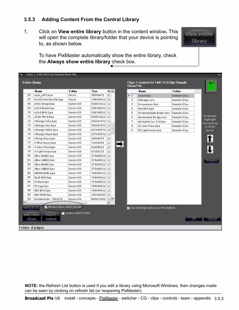
install - concepts - PixMaster - switcher - CG - clips - controls - team - appendix Broadcast Pix V8 3.5.3
3.5.3 Adding Content From the Central Library
1. Click on View entire library button in the content window. This will open the complete library/folder that your device is pointing to, as shown below.
To have PixMaster automatically show the entire library, check the Always show entire library check box.
NOTE: the Refresh List button is used if you edit a library using Microsoft Windows, then changes made can be seen by clicking on refresh list (or reopening PixMaster).
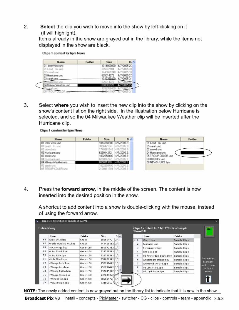
install - concepts - PixMaster - switcher - CG - clips - controls - team - appendix Broadcast Pix V8
2. Select the clip you wish to move into the show by left-clicking on it (it will highlight).
Items already in the show are grayed out in the library, while the items not displayed in the show are black.
3. Select where you wish to insert the new clip into the show by clicking on the show’s content list on the right side. In the illustration below Hurricane is selected, and so the 04 Milwaukee Weather clip will be inserted after the Hurricane clip.
4. Press the forward arrow, in the middle of the screen. The content is now inserted into the desired position in the show.
A shortcut to add content into a show is double-clicking with the mouse, instead of using the forward arrow.
NOTE: The newly added content is now grayed out on the library list to indicate that it is now in the show.
3.5.3
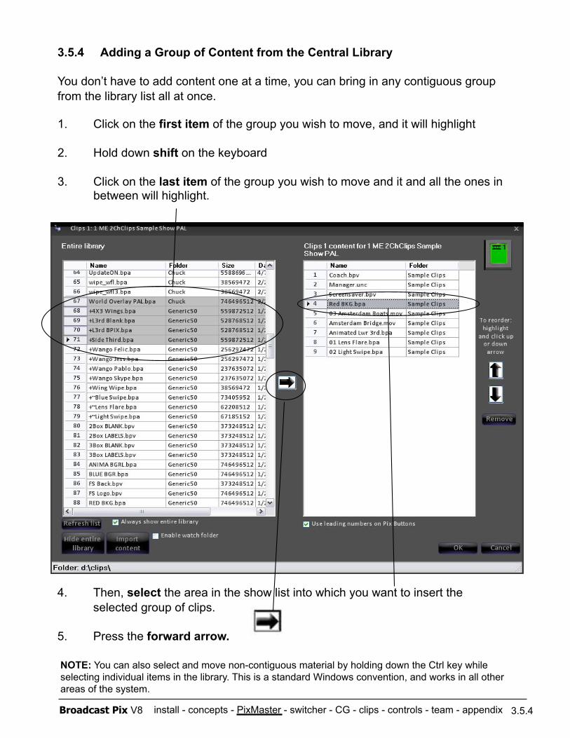
install - concepts - PixMaster - switcher - CG - clips - controls - team - appendix Broadcast Pix V8 3.5.4
3.5.4 Adding a Group of Content from the Central Library
You don’t have to add content one at a time, you can bring in any contiguous group from the library list all at once.
1. Click on the first item of the group you wish to move, and it will highlight
2. Hold down shift on the keyboard
3. Click on the last item of the group you wish to move and it and all the ones in between will highlight.
4. Then, select the area in the show list into which you want to insert the selected group of clips.
5. Press the forward arrow.
NOTE: You can also select and move non-contiguous material by holding down the Ctrl key while selecting individual items in the library. This is a standard Windows convention, and works in all other areas of the system.
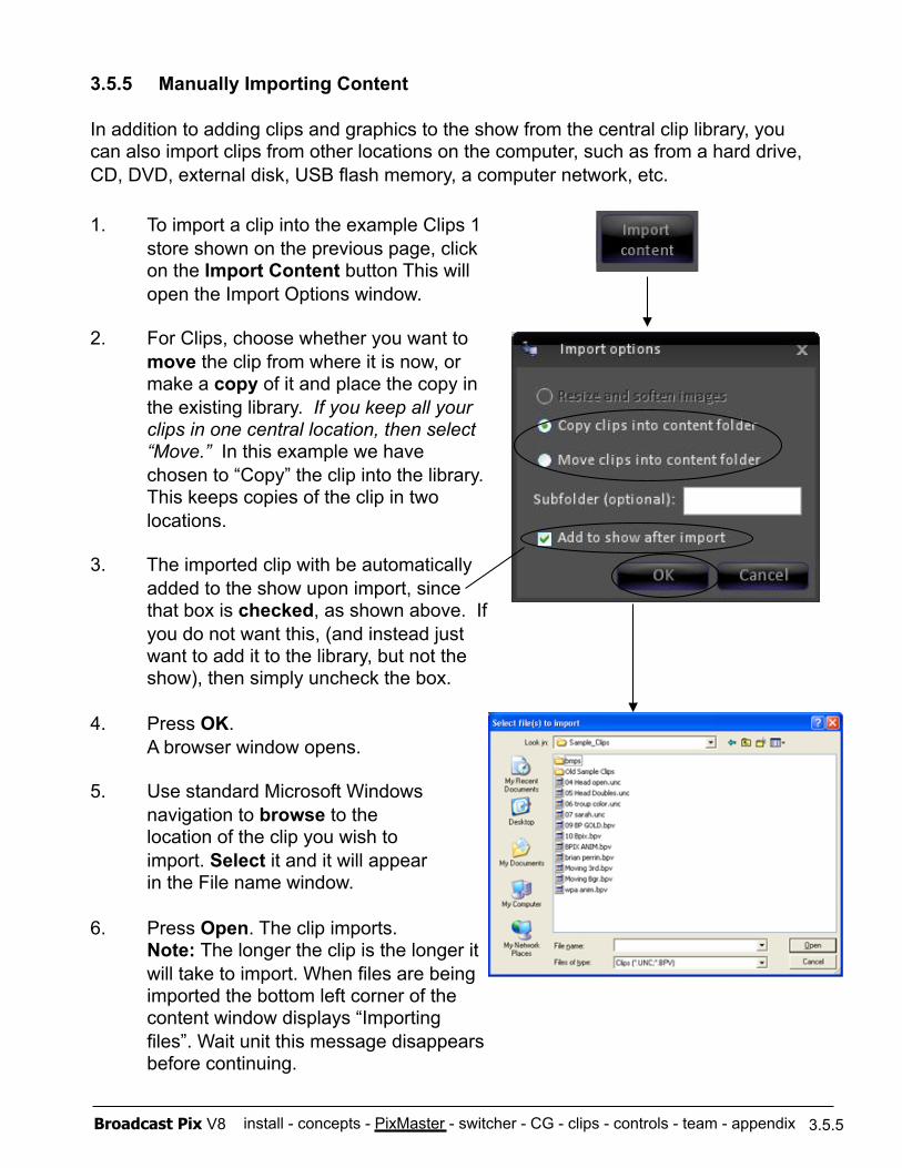
install - concepts - PixMaster - switcher - CG - clips - controls - team - appendix Broadcast Pix V8 3.5.5
1. To import a clip into the example Clips 1 store shown on the previous page, click
on the Import Content button This will open the Import Options window.
2. For Clips, choose whether you want to move the clip from where it is now, or make a copy of it and place the copy in the existing library. If you keep all your clips in one central location, then select “Move.” In this example we have chosen to “Copy” the clip into the library. This keeps copies of the clip in two locations.
3. The imported clip with be automatically added to the show upon import, since that box is checked, as shown above. If you do not want this, (and instead just want to add it to the library, but not the show), then simply uncheck the box.
4. Press OK. A browser window opens.
5. Use standard Microsoft Windows navigation to browse to the location of the clip you wish to import. Select it and it will appear in the File name window.
6. Press Open. The clip imports. Note: The longer the clip is the longer it will take to import. When files are being imported the bottom left corner of the content window displays “Importing files”. Wait unit this message disappears before continuing.
3.5.5 Manually Importing Content
In addition to adding clips and graphics to the show from the central clip library, you can also import clips from other locations on the computer, such as from a hard drive, CD, DVD, external disk, USB flash memory, a computer network, etc.
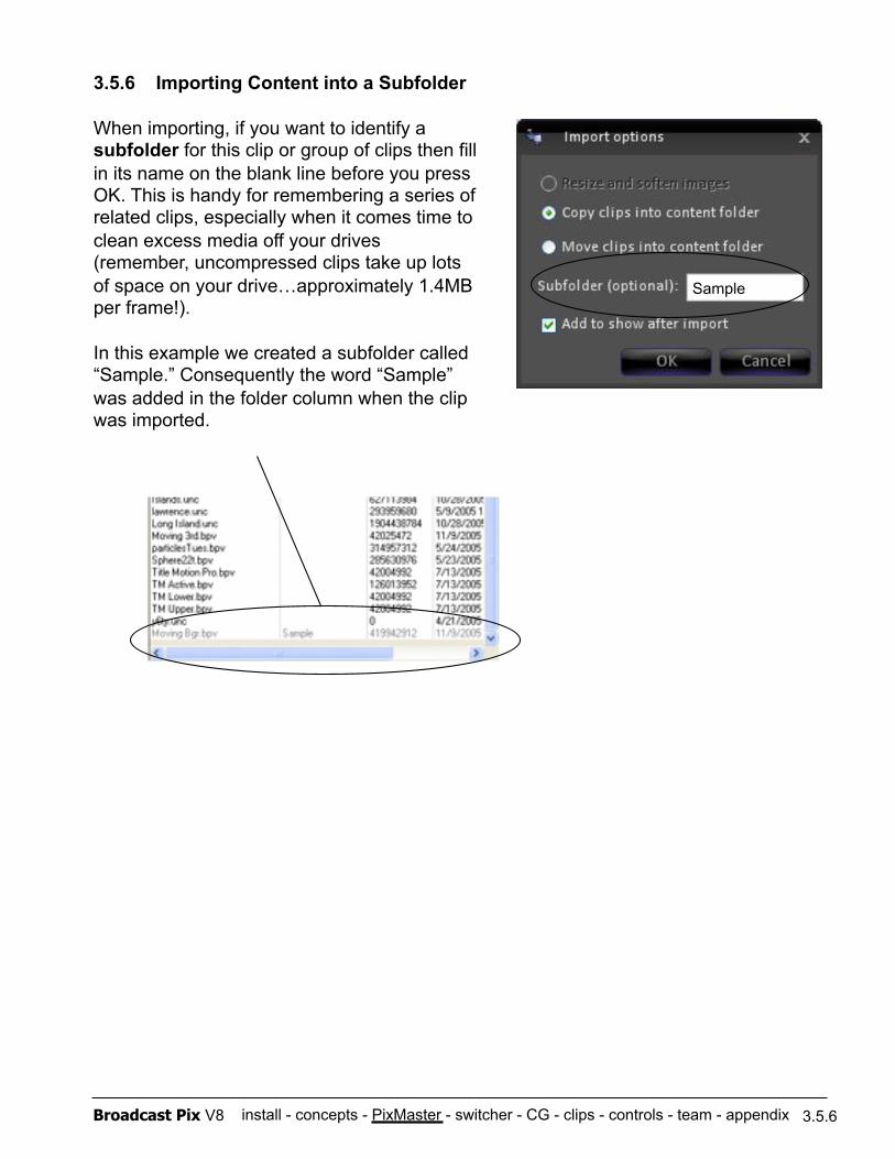
install - concepts - PixMaster - switcher - CG - clips - controls - team - appendix Broadcast Pix V8
Sample
3.5.6
3.5.6 Importing Content into a Subfolder
When importing, if you want to identify a subfolder for this clip or group of clips then fill in its name on the blank line before you press OK. This is handy for remembering a series of related clips, especially when it comes time to clean excess media off your drives (remember, uncompressed clips take up lots of space on your drive…approximately 1.4MB per frame!).
In this example we created a subfolder called “Sample.” Consequently the word “Sample” was added in the folder column when the clip was imported.
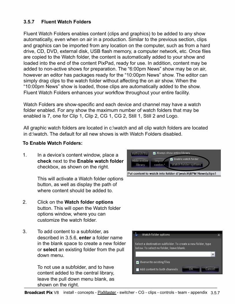
install - concepts - PixMaster - switcher - CG - clips - controls - team - appendix Broadcast Pix V8
3.5.7 Fluent Watch Folders
Fluent Watch Folders enables content (clips and graphics) to be added to any show automatically, even when on air in a production. Similar to the previous section, clips and graphics can be imported from any location on the computer, such as from a hard drive, CD, DVD, external disk, USB flash memory, a computer network, etc. Once files are copied to the Watch folder, the content is automatically added to your show and loaded into the end of the content PixPad, ready for use. In addition, content may be added to non-active shows for preparation. The “6:00pm News” show may be on air, however an editor has packages ready for the “10:00pm News” show. The editor can simply drag clips to the watch folder without affecting the on air show. When the “10:00pm News” show is loaded, those clips are automatically added to the show. Fluent Watch Folders enhances your workflow throughout your entire facility.
Watch Folders are show-specific and each device and channel may have a watch folder enabled. For any show the maximum number of watch folders that may be enabled is 7, one for Clip 1, Clip 2, CG 1, CG 2, Still 1, Still 2 and Logo.
All graphic watch folders are located in c:\watch and all clip watch folders are located in d:\watch. The default for all new shows is with Watch Folders disabled.
3.5.7
To Enable Watch Folders:
1. In a device’s content window, place a check next to the Enable watch folder checkbox, as shown on the right.
This will activate a Watch folder options button, as well as display the path of where content should be added to.
2. Click on the Watch folder options button. This will open the Watch folder options window, where you can customize the watch folder.
3. To add content to a subfolder, as described in 3.5.6, enter a folder name in the blank space to create a new folder or select an existing folder from the pull down menu.
To not use a subfolder, and to have content added to the central library, leave the pull down menu blank, as shown on the right.
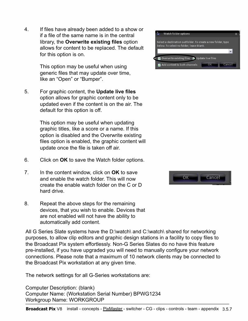
install - concepts - PixMaster - switcher - CG - clips - controls - team - appendix Broadcast Pix V8 3.5.7
4. If files have already been added to a show or if a file of the same name is in the central library, the Overwrite existing files option allows for content to be replaced. The default for this option is on.
This option may be useful when using generic files that may update over time, like an “Open” or “Bumper”.
5. For graphic content, the Update live files option allows for graphic content only to be updated even if the content is on the air. The default for this option is off.
This option may be useful when updating graphic titles, like a score or a name. If this option is disabled and the Overwrite existing files option is enabled, the graphic content will update once the file is taken off air.
6. Click on OK to save the Watch folder options.
7. In the content window, click on OK to save and enable the watch folder. This will now create the enable watch folder on the C or D hard drive.
8. Repeat the above steps for the remaining devices, that you wish to enable. Devices that are not enabled will not have the ability to automatically add content.
All G Series Slate systems have the D:\watch\ and C:\watch\ shared for networking purposes, to allow clip editors and graphic design stations in a facility to copy files to the Broadcast Pix system effortlessly. Non-G Series Slates do no have this feature pre-installed, if you have upgraded you will need to manually configure your network connections. Please note that a maximum of 10 network clients may be connected to the Broadcast Pix workstation at any given time.
The network settings for all G-Series workstations are:
Computer Description: (blank) Computer Name: (Workstation Serial Number) BPWG1234 Workgroup Name: WORKGROUP
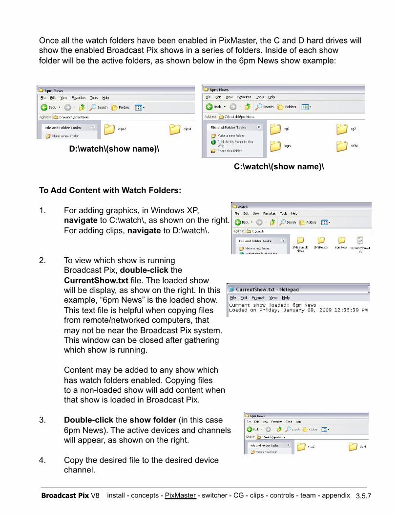
install - concepts - PixMaster - switcher - CG - clips - controls - team - appendix Broadcast Pix V8 3.5.7
Once all the watch folders have been enabled in PixMaster, the C and D hard drives will show the enabled Broadcast Pix shows in a series of folders. Inside of each show folder will be the active folders, as shown below in the 6pm News show example:
To Add Content with Watch Folders:
1. For adding graphics, in Windows XP, navigate to C:\watch\, as shown on the right. For adding clips, navigate to D:\watch\.
2. To view which show is running Broadcast Pix, double-click the CurrentShow.txt file. The loaded show will be display, as show on the right. In this example, “6pm News” is the loaded show. This text file is helpful when copying files from remote/networked computers, that may not be near the Broadcast Pix system. This window can be closed after gathering which show is running.
Content may be added to any show which has watch folders enabled. Copying files to a non-loaded show will add content when that show is loaded in Broadcast Pix.
3. Double-click the show folder (in this case 6pm News). The active devices and channels will appear, as shown on the right.
4. Copy the desired file to the desired device channel.
D:\watch\(show name)\
C:\watch\(show name)\
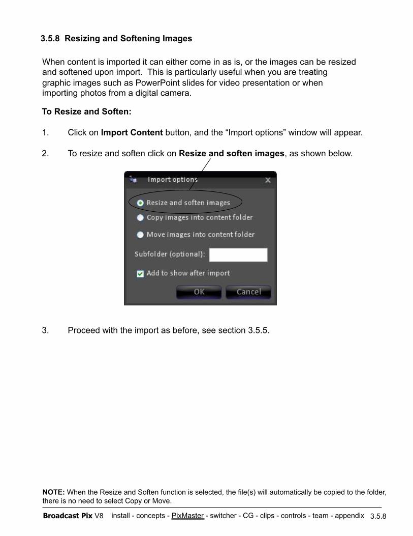
install - concepts - PixMaster - switcher - CG - clips - controls - team - appendix Broadcast Pix V8
To Resize and Soften:
1. Click on Import Content button, and the “Import options” window will appear.
2. To resize and soften click on Resize and soften images, as shown below.
3. Proceed with the import as before, see section 3.5.5.
3.5.8
3.5.8 Resizing and Softening Images
When content is imported it can either come in as is, or the images can be resized and softened upon import. This is particularly useful when you are treating graphic images such as PowerPoint slides for video presentation or when importing photos from a digital camera.
NOTE: When the Resize and Soften function is selected, the file(s) will automatically be copied to the folder, there is no need to select Copy or Move.
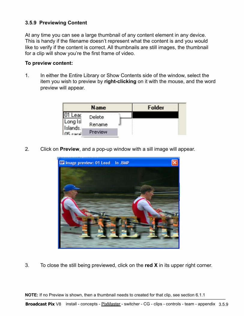
install - concepts - PixMaster - switcher - CG - clips - controls - team - appendix Broadcast Pix V8
To preview content:
1. In either the Entire Library or Show Contents side of the window, select the item you wish to preview by right-clicking on it with the mouse, and the word preview will appear.
2. Click on Preview, and a pop-up window with a sill image will appear.
3. To close the still being previewed, click on the red X in its upper right corner.
3.5.9
3.5.9 Previewing Content
At any time you can see a large thumbnail of any content element in any device. This is handy if the filename doesn’t represent what the content is and you would like to verify if the content is correct. All thumbnails are still images, the thumbnail for a clip will show you’re the first frame of video.
NOTE: If no Preview is shown, then a thumbnail needs to created for that clip, see section 6.1.1
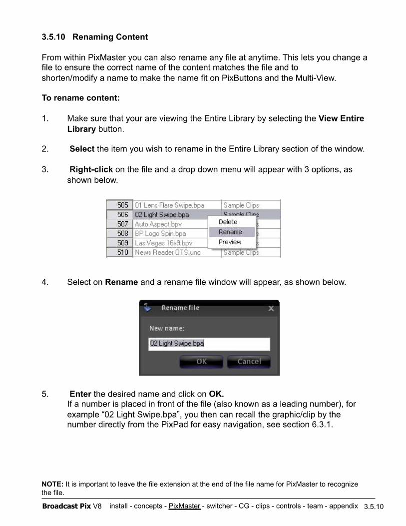
install - concepts - PixMaster - switcher - CG - clips - controls - team - appendix Broadcast Pix V8
3.5.10 Renaming Content
From within PixMaster you can also rename any file at anytime. This lets you change a file to ensure the correct name of the content matches the file and to shorten/modify a name to make the name fit on PixButtons and the Multi-View.
To rename content:
1. Make sure that your are viewing the Entire Library by selecting the View Entire Library button.
2. Select the item you wish to rename in the Entire Library section of the window.
3. Right-click on the file and a drop down menu will appear with 3 options, as shown below.
4. Select on Rename and a rename file window will appear, as shown below.
5. Enter the desired name and click on OK. If a number is placed in front of the file (also known as a leading number), for example “02 Light Swipe.bpa”, you then can recall the graphic/clip by the number directly from the PixPad for easy navigation, see section 6.3.1.
3.5.10
NOTE: It is important to leave the file extension at the end of the file name for PixMaster to recognize the file.
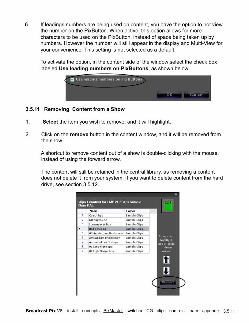
install - concepts - PixMaster - switcher - CG - clips - controls - team - appendix Broadcast Pix V8
3.5.11 Removing Content from a Show
1. Select the item you wish to remove, and it will highlight.
2. Click on the remove button in the content window, and it will be removed from the show.
A shortcut to remove content out of a show is double-clicking with the mouse, instead of using the forward arrow.
The content will still be retained in the central library, as removing a content does not delete it from your system. If you want to delete content from the hard drive, see section 3.5.12.
3.5.11
6. If leadings numbers are being used on content, you have the option to not view the number on the PixButton. When active, this option allows for more characters to be used on the PixButton, instead of space being taken up by numbers. However the number will still appear in the display and Multi-View for your convenience. This setting is not selected as a default.
To activate the option, in the content side of the window select the check box labeled Use leading numbers on PixButtons, as shown below.
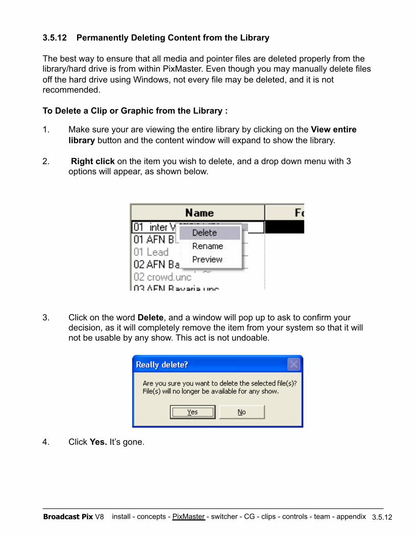
install - concepts - PixMaster - switcher - CG - clips - controls - team - appendix Broadcast Pix V8
3.5.12 Permanently Deleting Content from the Library
The best way to ensure that all media and pointer files are deleted properly from the library/hard drive is from within PixMaster. Even though you may manually delete files off the hard drive using Windows, not every file may be deleted, and it is not recommended.
To Delete a Clip or Graphic from the Library :
1. Make sure your are viewing the entire library by clicking on the View entire library button and the content window will expand to show the library.
2. Right click on the item you wish to delete, and a drop down menu with 3 options will appear, as shown below.
3. Click on the word Delete, and a window will pop up to ask to confirm your decision, as it will completely remove the item from your system so that it will not be usable by any show. This act is not undoable.
4. Click Yes. It’s gone.
3.5.12
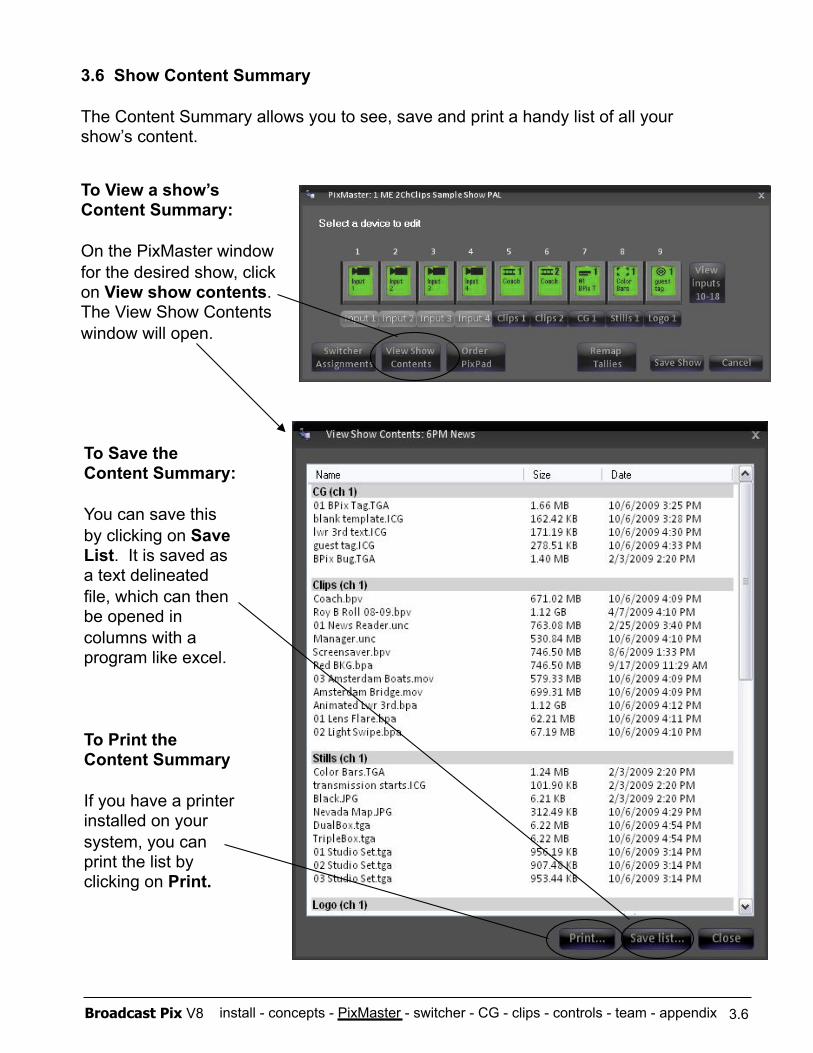
install - concepts - PixMaster - switcher - CG - clips - controls - team - appendix Broadcast Pix V8 3.6
. 3.6 Show Content Summary
The Content Summary allows you to see, save and print a handy list of all your show’s content.
To View a show’s Content Summary:
On the PixMaster window for the desired show, click on View show contents. The View Show Contents window will open.
To Save the Content Summary:
You can save this by clicking on Save List. It is saved as a text delineated file, which can then be opened in columns with a program like excel.
To Print the Content Summary
If you have a printer installed on your system, you can print the list by clicking on Print.
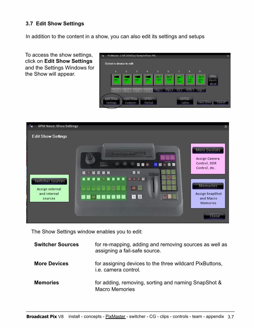
install - concepts - PixMaster - switcher - CG - clips - controls - team - appendix Broadcast Pix V8 3.7
3.7 Edit Show Settings
In addition to the content in a show, you can also edit its settings and setups
To access the show settings, click on Edit Show Settings and the Settings Windows for the Show will appear.
The Show Settings window enables you to edit:
Switcher Sources for re-mapping, adding and removing sources as well as assigning a fail-safe source.
More Devices for assigning devices to the three wildcard PixButtons, i.e. camera control.
Memories for adding, removing, sorting and naming SnapShot & Macro Memories
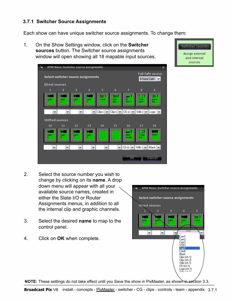
install - concepts - PixMaster - switcher - CG - clips - controls - team - appendix Broadcast Pix V8
3.7.1 Switcher Source Assignments
Each show can have unique switcher source assignments. To change them:
1. On the Show Settings window, click on the Switcher sources button. The Switcher source assignments window will open showing all 18 mapable input sources.
2. Select the source number you wish to change by clicking on its name. A drop down menu will appear with all your available source names, created in either the Slate I/O or Router Assignments menus, in addition to all the internal clip and graphic channels.
3. Select the desired name to map to the control panel.
4. Click on OK when complete.
3.7.1
NOTE: These settings do not take effect until you Save the show in PixMaster, as shown in section 3.3.
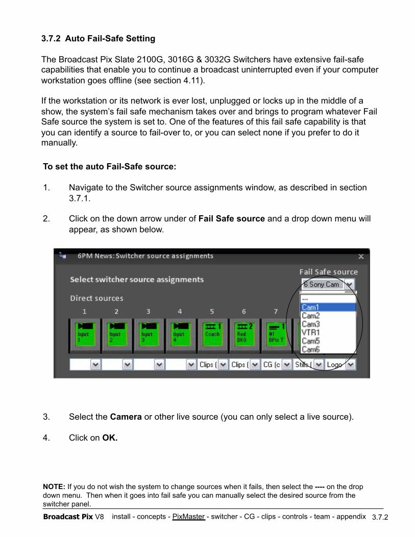
install - concepts - PixMaster - switcher - CG - clips - controls - team - appendix Broadcast Pix V8
To set the auto Fail-Safe source:
1. Navigate to the Switcher source assignments window, as described in section 3.7.1.
2. Click on the down arrow under of Fail Safe source and a drop down menu will appear, as shown below.
3. Select the Camera or other live source (you can only select a live source).
4. Click on OK.
NOTE: If you do not wish the system to change sources when it fails, then select the ---- on the drop down menu. Then when it goes into fail safe you can manually select the desired source from the switcher panel.
3.7.2
3.7.2 Auto Fail-Safe Setting
The Broadcast Pix Slate 2100G, 3016G & 3032G Switchers have extensive fail-safe capabilities that enable you to continue a broadcast uninterrupted even if your computer workstation goes offline (see section 4.11).
If the workstation or its network is ever lost, unplugged or locks up in the middle of a show, the system’s fail safe mechanism takes over and brings to program whatever Fail Safe source the system is set to. One of the features of this fail safe capability is that you can identify a source to fail-over to, or you can select none if you prefer to do it manually.
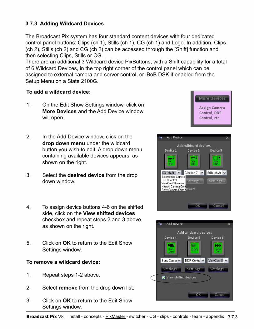
install - concepts - PixMaster - switcher - CG - clips - controls - team - appendix Broadcast Pix V8 3.7.3
To add a wildcard device:
1. On the Edit Show Settings window, click on More Devices and the Add Device window will open.
2. In the Add Device window, click on the drop down menu under the wildcard button you wish to edit. A drop down menu containing available devices appears, as shown on the right.
3. Select the desired device from the drop down window.
4. To assign device buttons 4-6 on the shifted side, click on the View shifted devices checkbox and repeat steps 2 and 3 above, as shown on the right.
5. Click on OK to return to the Edit Show Settings window.
To remove a wildcard device:
1. Repeat steps 1-2 above.
2. Select remove from the drop down list.
3. Click on OK to return to the Edit Show Settings window.
3.7.3 Adding Wildcard Devices
The Broadcast Pix system has four standard content devices with four dedicated control panel buttons: Clips (ch 1), Stills (ch 1), CG (ch 1) and Logo. In addition, Clips (ch 2), Stills (ch 2) and CG (ch 2) can be accessed through the [Shift] function and then selecting Clips, Stills or CG. There are an additional 3 Wildcard device PixButtons, with a Shift capability for a total of 6 Wildcard Devices, in the top right corner of the control panel which can be assigned to external camera and server control, or iBoB DSK if enabled from the Setup Menu on a Slate 2100G.
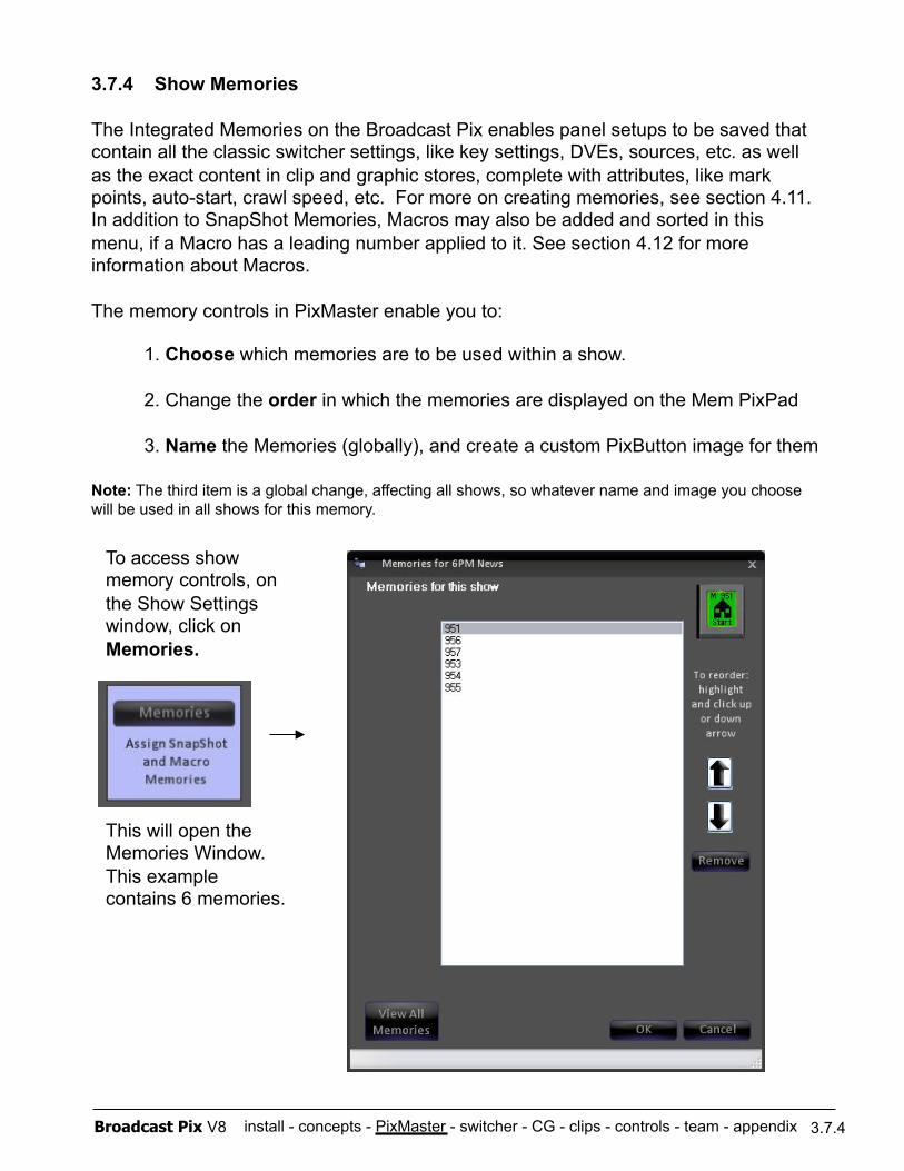
install - concepts - PixMaster - switcher - CG - clips - controls - team - appendix Broadcast Pix V8 3.7.4
3.7.4 Show Memories
The Integrated Memories on the Broadcast Pix enables panel setups to be saved that contain all the classic switcher settings, like key settings, DVEs, sources, etc. as well as the exact content in clip and graphic stores, complete with attributes, like mark points, auto-start, crawl speed, etc. For more on creating memories, see section 4.11. In addition to SnapShot Memories, Macros may also be added and sorted in this menu, if a Macro has a leading number applied to it. See section 4.12 for more information about Macros.
The memory controls in PixMaster enable you to:
Note: The third item is a global change, affecting all shows, so whatever name and image you choose will be used in all shows for this memory.
To access show memory controls, on the Show Settings window, click on Memories.
This will open the Memories Window. This example contains 6 memories.
1. Choose which memories are to be used within a show.
2. Change the order in which the memories are displayed on the Mem PixPad
3. Name the Memories (globally), and create a custom PixButton image for them
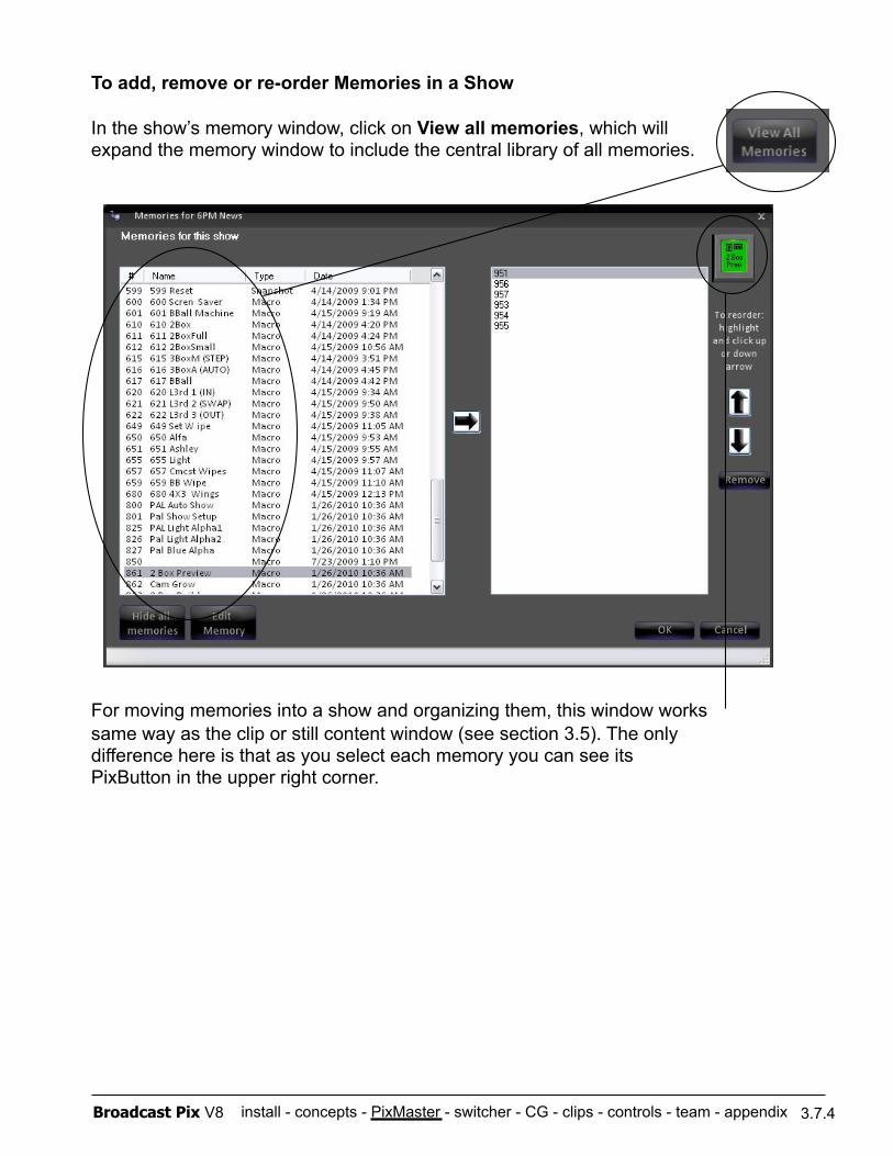
install - concepts - PixMaster - switcher - CG - clips - controls - team - appendix Broadcast Pix V8 3.7.4
To add, remove or re-order Memories in a Show
In the show’s memory window, click on View all memories, which will expand the memory window to include the central library of all memories.
For moving memories into a show and organizing them, this window works same way as the clip or still content window (see section 3.5). The only difference here is that as you select each memory you can see its PixButton in the upper right corner.
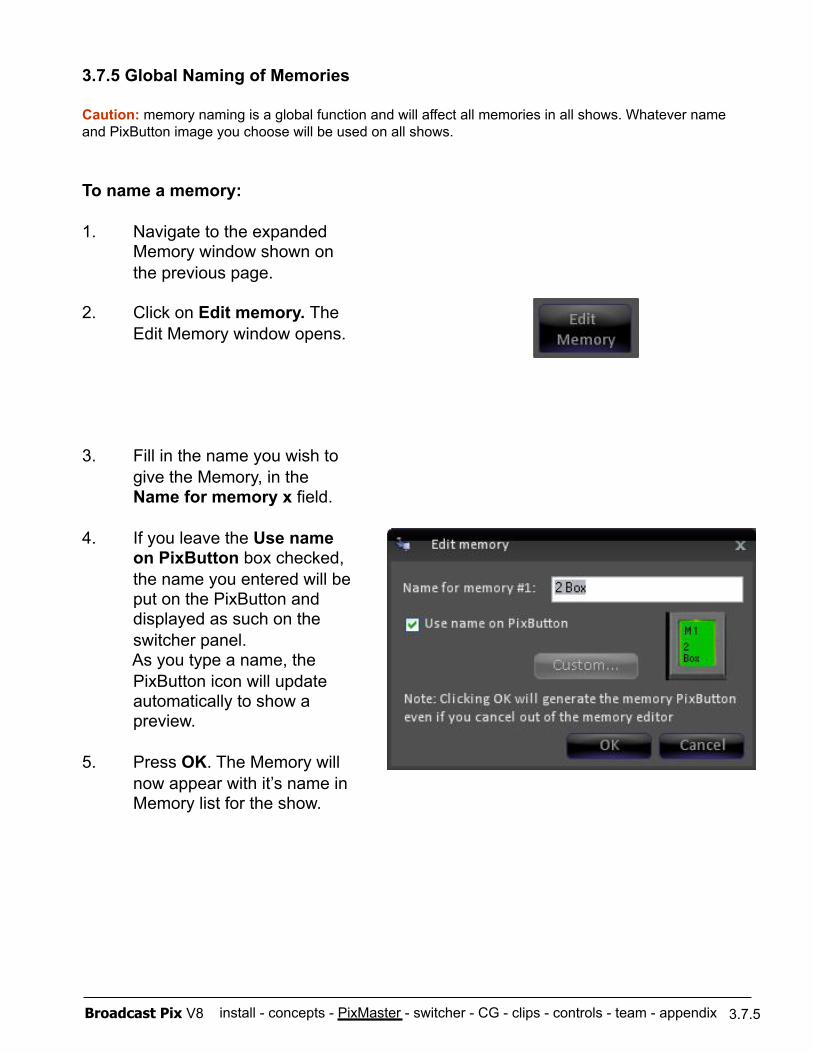
install - concepts - PixMaster - switcher - CG - clips - controls - team - appendix Broadcast Pix V8
3.7.5 Global Naming of Memories
Caution: memory naming is a global function and will affect all memories in all shows. Whatever name and PixButton image you choose will be used on all shows.
To name a memory:
1. Navigate to the expanded Memory window shown on the previous page.
2. Click on Edit memory. The Edit Memory window opens.
3. Fill in the name you wish to give the Memory, in the Name for memory x field.
4. If you leave the Use name on PixButton box checked, the name you entered will be put on the PixButton and displayed as such on the switcher panel. As you type a name, the PixButton icon will update automatically to show a preview.
5. Press OK. The Memory will now appear with it’s name in Memory list for the show.
3.7.5
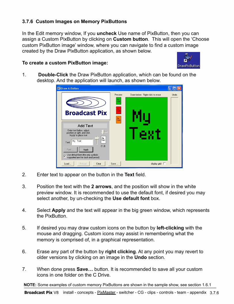
install - concepts - PixMaster - switcher - CG - clips - controls - team - appendix Broadcast Pix V8
3.7.6 Custom Images on Memory PixButtons
In the Edit memory window, If you uncheck Use name of PixButton, then you can assign a Custom PixButton by clicking on Custom button. This will open the ‘Choose custom PixButton image’ window, where you can navigate to find a custom image created by the Draw PixButton application, as shown below.
To create a custom PixButton image:
1. Double-Click the Draw PixButton application, which can be found on the desktop. And the application will launch, as shown below.
2. Enter text to appear on the button in the Text field.
3. Position the text with the 2 arrows, and the position will show in the white preview window. It is recommended to use the default font, if desired you may select another, by un-checking the Use default font box.
4. Select Apply and the text will appear in the big green window, which represents the PixButton.
5. If desired you may draw custom icons on the button by left-clicking with the mouse and dragging. Custom icons may assist in remembering what the memory is comprised of, in a graphical representation.
6. Erase any part of the button by right clicking. At any point you may revert to older versions by clicking on an image in the Undo section.
7. When done press Save… button. It is recommended to save all your custom icons in one folder on the C Drive.
3.7.6
NOTE: Some examples of custom memory PixButtons are shown in the sample show, see section 1.6.1
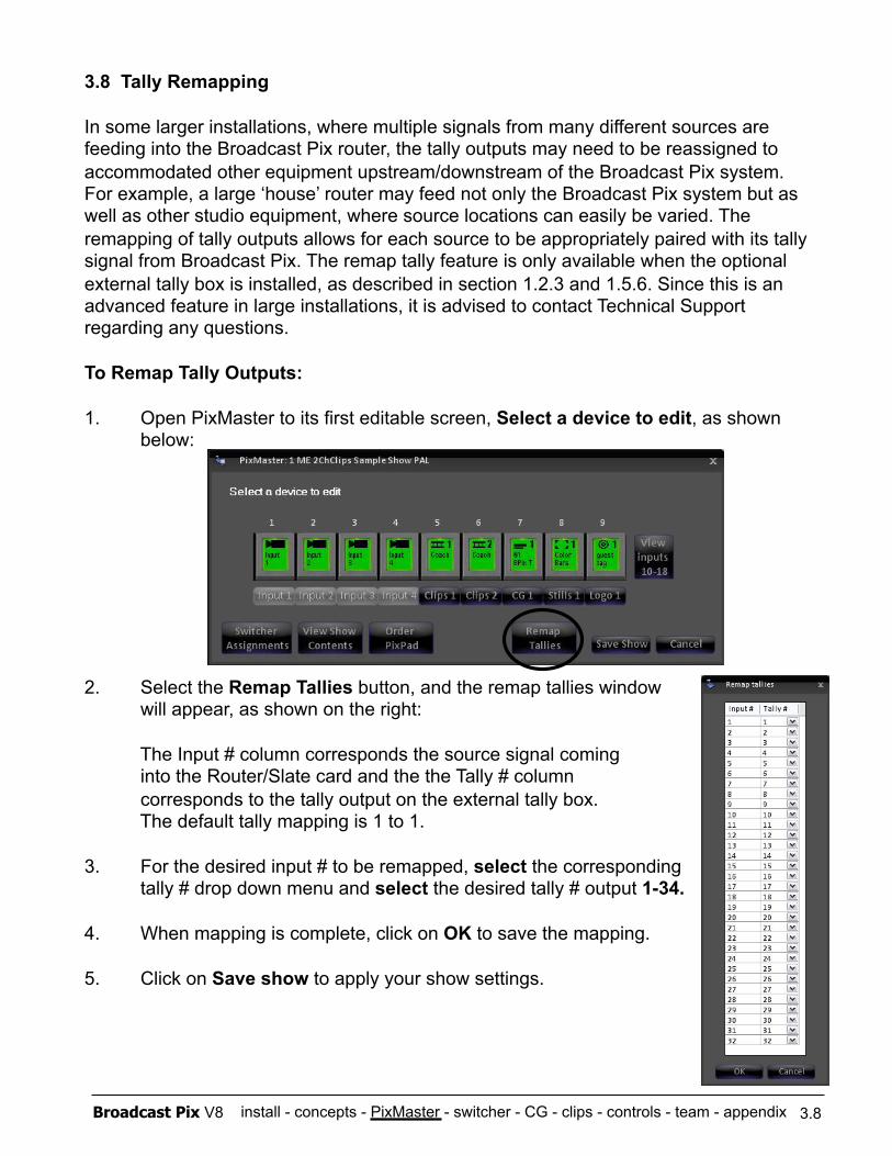
install - concepts - PixMaster - switcher - CG - clips - controls - team - appendix Broadcast Pix V8
3.8 Tally Remapping
In some larger installations, where multiple signals from many different sources are feeding into the Broadcast Pix router, the tally outputs may need to be reassigned to accommodated other equipment upstream/downstream of the Broadcast Pix system. For example, a large ‘house’ router may feed not only the Broadcast Pix system but as well as other studio equipment, where source locations can easily be varied. The remapping of tally outputs allows for each source to be appropriately paired with its tally signal from Broadcast Pix. The remap tally feature is only available when the optional external tally box is installed, as described in section 1.2.3 and 1.5.6. Since this is an advanced feature in large installations, it is advised to contact Technical Support regarding any questions.
To Remap Tally Outputs:
1. Open PixMaster to its first editable screen, Select a device to edit, as shown below:
2. Select the Remap Tallies button, and the remap tallies window will appear, as shown on the right:
The Input # column corresponds the source signal coming into the Router/Slate card and the the Tally # column corresponds to the tally output on the external tally box. The default tally mapping is 1 to 1.
3. For the desired input # to be remapped, select the corresponding tally # drop down menu and select the desired tally # output 1-34.
4. When mapping is complete, click on OK to save the mapping.
5. Click on Save show to apply your show settings.
3.8
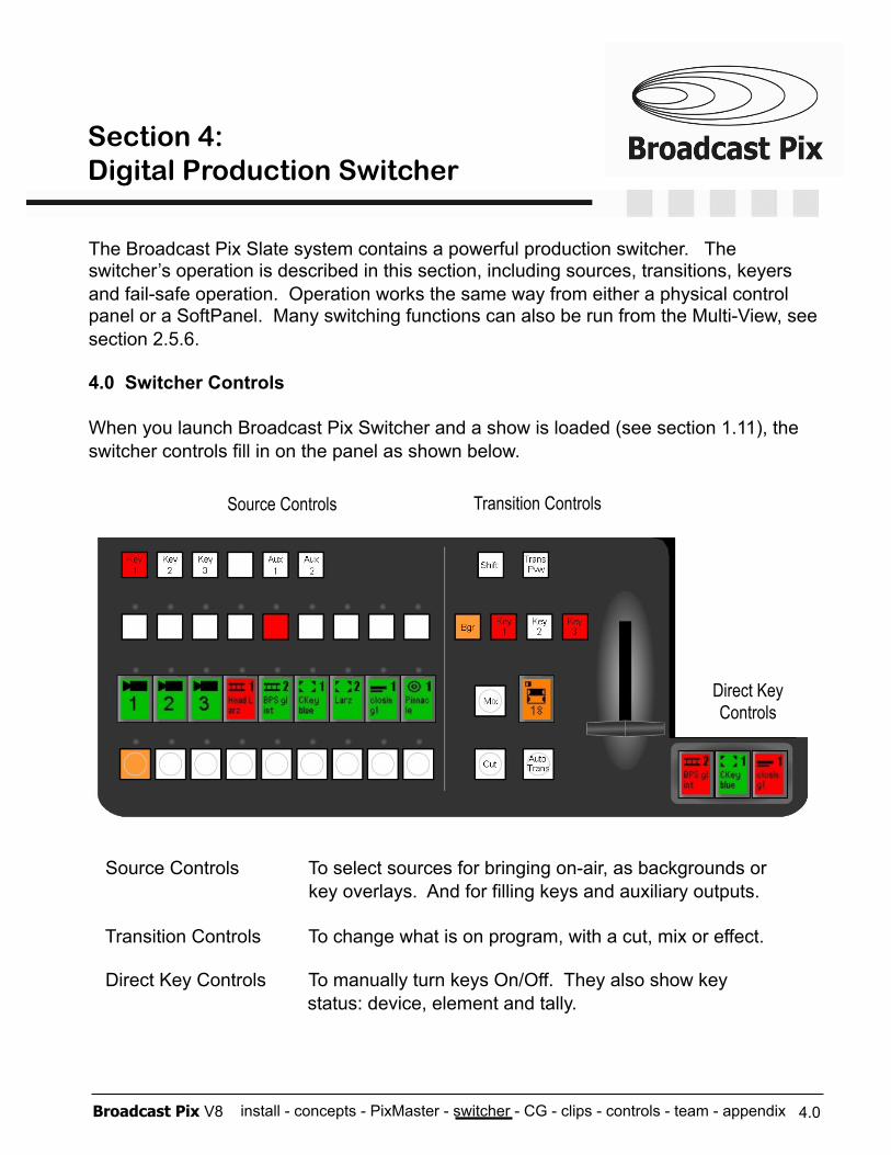
install - concepts - PixMaster - switcher - CG - clips - controls - team - appendix Broadcast Pix V8
The Broadcast Pix Slate system contains a powerful production switcher. The switcher’s operation is described in this section, including sources, transitions, keyers and fail-safe operation. Operation works the same way from either a physical control panel or a SoftPanel. Many switching functions can also be run from the Multi-View, see section 2.5.6.
4.0 Switcher Controls
When you launch Broadcast Pix Switcher and a show is loaded (see section 1.11), the switcher controls fill in on the panel as shown below.
Source Controls To select sources for bringing on-air, as backgrounds or key overlays. And for filling keys and auxiliary outputs.
Transition Controls To change what is on program, with a cut, mix or effect.
Direct Key Controls To manually turn keys On/Off. They also show key status: device, element and tally.
Transition Controls Source Controls
4.0
Direct Key Controls
Section 4: Digital Production Switcher
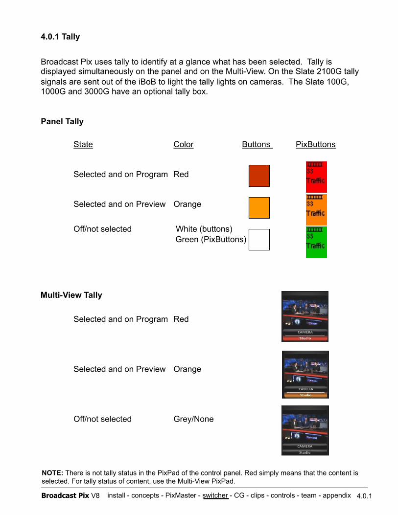
install - concepts - PixMaster - switcher - CG - clips - controls - team - appendix Broadcast Pix V8
Multi-View Tally
4.0.1 Tally
Broadcast Pix uses tally to identify at a glance what has been selected. Tally is displayed simultaneously on the panel and on the Multi-View. On the Slate 2100G tally signals are sent out of the iBoB to light the tally lights on cameras. The Slate 100G, 1000G and 3000G have an optional tally box.
Panel Tally
State Color Buttons PixButtons
Selected and on Program Red
Selected and on Preview Orange
Off/not selected White (buttons) Green (PixButtons)
Selected and on Program Red
Selected and on Preview Orange
Off/not selected Grey/None
4.0.1
NOTE: There is not tally status in the PixPad of the control panel. Red simply means that the content is selected. For tally status of content, use the Multi-View PixPad.
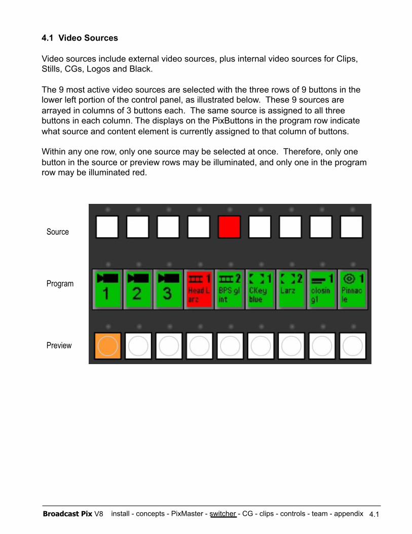
install - concepts - PixMaster - switcher - CG - clips - controls - team - appendix Broadcast Pix V8
4.1 Video Sources
Video sources include external video sources, plus internal video sources for Clips, Stills, CGs, Logos and Black.
The 9 most active video sources are selected with the three rows of 9 buttons in the lower left portion of the control panel, as illustrated below. These 9 sources are arrayed in columns of 3 buttons each. The same source is assigned to all three buttons in each column. The displays on the PixButtons in the program row indicate what source and content element is currently assigned to that column of buttons.
Within any one row, only one source may be selected at once. Therefore, only one button in the source or preview rows may be illuminated, and only one in the program row may be illuminated red.
Source
Program
Preview
4.1
install - concepts - PixMaster - switcher - CG - clips - controls - team - appendix Broadcast Pix V8
Program Row
The Program Row Indicates which source is on the air, which will always be illuminated red. Other available sources will be illuminated green, and buttons with no video source assigned will not be illuminated.
The PixButtons used in this row indicate the contents of the source, including what device is currently assigned, as well as the currently selected content element on the device. For example, in the above illustration the on-air source is the first channel of clip store, which has an the active clip called “Head Larz”.
Preview Row
The Preview Row is used to select which source is selected on preview/preset, which will be illuminated orange, during a transition the preview row illuminates red and returns to orange at the end of the transition.
Source Row
The Source Row is used to select which source is used to fill a key, or an auxiliary output, sources will be illuminated orange to signify that they are selected and on preview and turn to red once that source is on program.
4.1
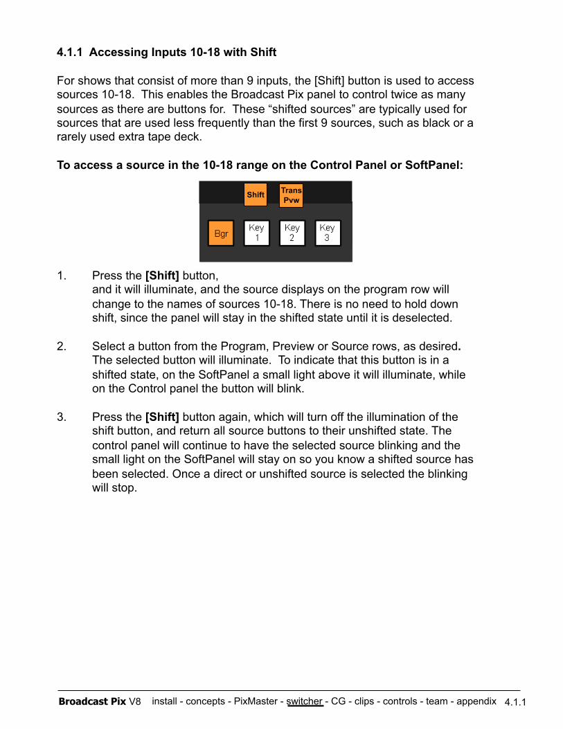
install - concepts - PixMaster - switcher - CG - clips - controls - team - appendix Broadcast Pix V8
4.1.1 Accessing Inputs 10-18 with Shift
For shows that consist of more than 9 inputs, the [Shift] button is used to access sources 10-18. This enables the Broadcast Pix panel to control twice as many sources as there are buttons for. These “shifted sources” are typically used for sources that are used less frequently than the first 9 sources, such as black or a rarely used extra tape deck.
To access a source in the 10-18 range on the Control Panel or SoftPanel:
1. Press the [Shift] button, and it will illuminate, and the source displays on the program row will change to the names of sources 10-18. There is no need to hold down shift, since the panel will stay in the shifted state until it is deselected.
2. Select a button from the Program, Preview or Source rows, as desired. The selected button will illuminate. To indicate that this button is in a shifted state, on the SoftPanel a small light above it will illuminate, while on the Control panel the button will blink.
3. Press the [Shift] button again, which will turn off the illumination of the shift button, and return all source buttons to their unshifted state. The control panel will continue to have the selected source blinking and the small light on the SoftPanel will stay on so you know a shifted source has been selected. Once a direct or unshifted source is selected the blinking will stop.
4.1.1
Trans Pvw
Shift
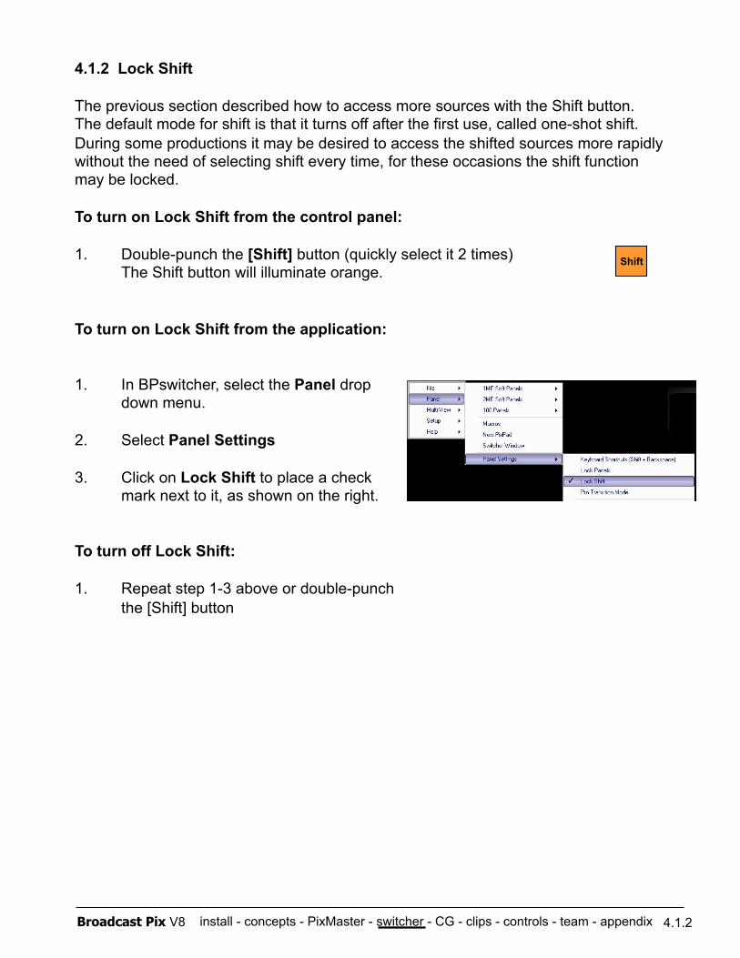
install - concepts - PixMaster - switcher - CG - clips - controls - team - appendix Broadcast Pix V8
4.1.2 Lock Shift
The previous section described how to access more sources with the Shift button. The default mode for shift is that it turns off after the first use, called one-shot shift. During some productions it may be desired to access the shifted sources more rapidly without the need of selecting shift every time, for these occasions the shift function may be locked.
To turn on Lock Shift from the control panel:
1. Double-punch the [Shift] button (quickly select it 2 times) The Shift button will illuminate orange.
To turn on Lock Shift from the application:
1. In BPswitcher, select the Panel drop down menu.
2. Select Panel Settings
3. Click on Lock Shift to place a check mark next to it, as shown on the right.
To turn off Lock Shift:
1. Repeat step 1-3 above or double-punch the [Shift] button
4.1.2
Shift
✓
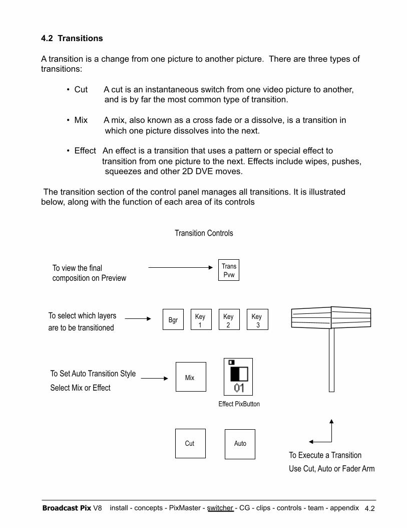
install - concepts - PixMaster - switcher - CG - clips - controls - team - appendix Broadcast Pix V8
4.2 Transitions
A transition is a change from one picture to another picture. There are three types of transitions:
• Cut A cut is an instantaneous switch from one video picture to another, and is by far the most common type of transition.
• Mix A mix, also known as a cross fade or a dissolve, is a transition in which one picture dissolves into the next.
• Effect An effect is a transition that uses a pattern or special effect to transition from one picture to the next. Effects include wipes, pushes,
squeezes and other 2D DVE moves.
The transition section of the control panel manages all transitions. It is illustrated below, along with the function of each area of its controls
Cut Auto
Trans Pvw
Key 1 Bgr
Mix
Key 2
Key 3
To select which layers are to be transitioned
To Set Auto Transition Style Select Mix or Effect
To Execute a Transition Use Cut, Auto or Fader Arm
To view the final composition on Preview
Transition Controls
Effect PixButton
4.2
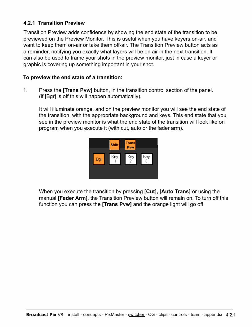
install - concepts - PixMaster - switcher - CG - clips - controls - team - appendix Broadcast Pix V8
To preview the end state of a transition:
1. Press the [Trans Pvw] button, in the transition control section of the panel. (if [Bgr] is off this will happen automatically).
It will illuminate orange, and on the preview monitor you will see the end state of the transition, with the appropriate background and keys. This end state that you see in the preview monitor is what the end state of the transition will look like on program when you execute it (with cut, auto or the fader arm).
When you execute the transition by pressing [Cut], [Auto Trans] or using the manual [Fader Arm], the Transition Preview button will remain on. To turn off this function you can press the [Trans Pvw] and the orange light will go off.
4.2.1
4.2.1 Transition Preview
Transition Preview adds confidence by showing the end state of the transition to be previewed on the Preview Monitor. This is useful when you have keyers on-air, and want to keep them on-air or take them off-air. The Transition Preview button acts as a reminder, notifying you exactly what layers will be on air in the next transition. It can also be used to frame your shots in the preview monitor, just in case a keyer or graphic is covering up something important in your shot.
Trans Pvw
Shift
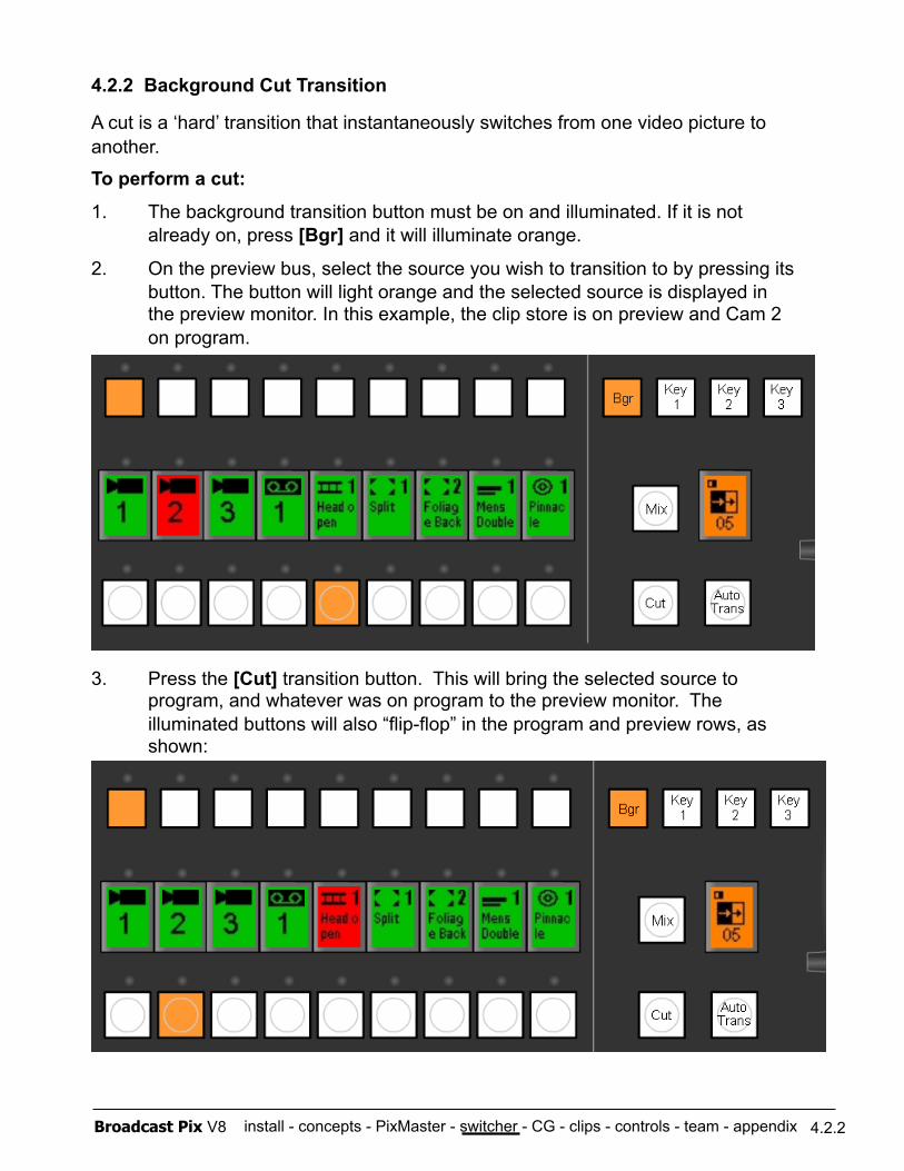
install - concepts - PixMaster - switcher - CG - clips - controls - team - appendix Broadcast Pix V8
4.2.2 Background Cut Transition
A cut is a ‘hard’ transition that instantaneously switches from one video picture to another.
To perform a cut:
1. The background transition button must be on and illuminated. If it is not already on, press [Bgr] and it will illuminate orange.
2. On the preview bus, select the source you wish to transition to by pressing its button. The button will light orange and the selected source is displayed in the preview monitor. In this example, the clip store is on preview and Cam 2 on program.
3. Press the [Cut] transition button. This will bring the selected source to program, and whatever was on program to the preview monitor. The illuminated buttons will also “flip-flop” in the program and preview rows, as shown:
4.2.2
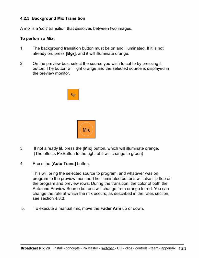
install - concepts - PixMaster - switcher - CG - clips - controls - team - appendix Broadcast Pix V8
4.2.3 Background Mix Transition
A mix is a ‘soft’ transition that dissolves between two images.
To perform a Mix:
1. The background transition button must be on and illuminated. If it is not already on, press [Bgr], and it will illuminate orange.
2. On the preview bus, select the source you wish to cut to by pressing it button. The button will light orange and the selected source is displayed in the preview monitor.
3. If not already lit, press the [Mix] button, which will illuminate orange. (The effects PixButton to the right of it will change to green)
4. Press the [Auto Trans] button.
This will bring the selected source to program, and whatever was on program to the preview monitor. The illuminated buttons will also flip-flop on the program and preview rows. During the transition, the color of both the Auto and Preview Source buttons will change from orange to red. You can change the rate at which the mix occurs, as described in the rates section, see section 4.3.3.
5. To execute a manual mix, move the Fader Arm up or down.
Bgr
Mix
4.2.3
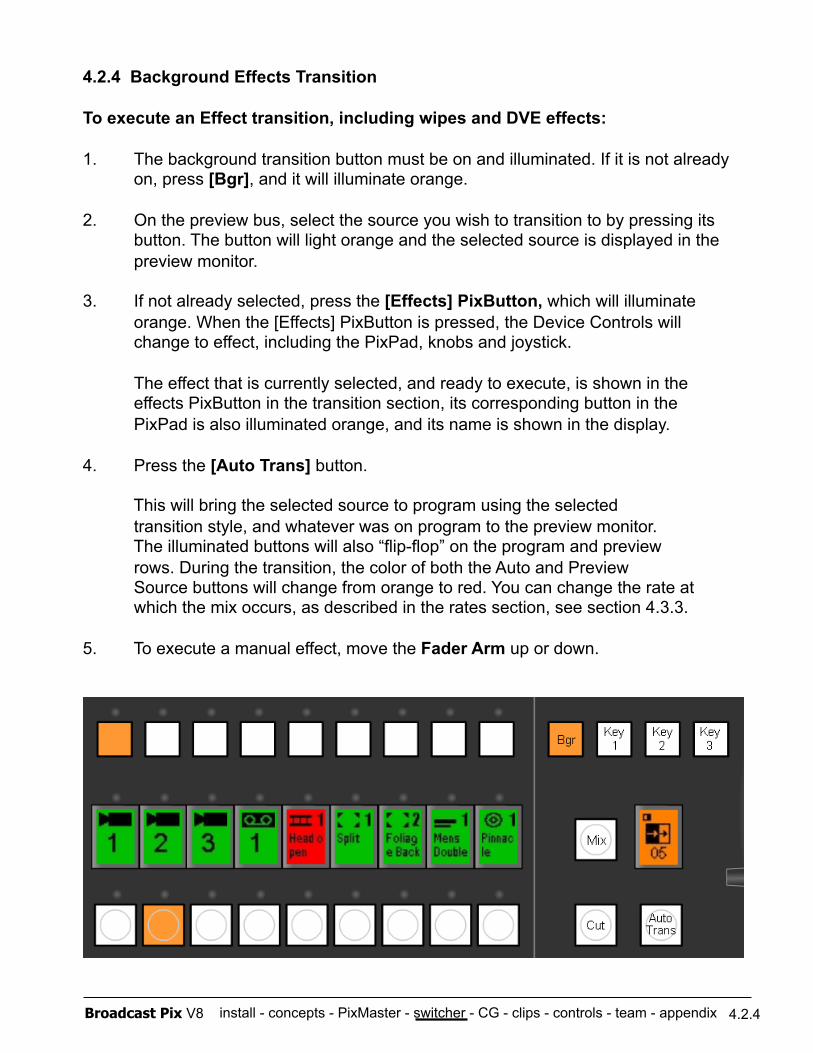
install - concepts - PixMaster - switcher - CG - clips - controls - team - appendix Broadcast Pix V8
4.2.4 Background Effects Transition
To execute an Effect transition, including wipes and DVE effects:
1. The background transition button must be on and illuminated. If it is not already on, press [Bgr], and it will illuminate orange.
2. On the preview bus, select the source you wish to transition to by pressing its button. The button will light orange and the selected source is displayed in the preview monitor.
3. If not already selected, press the [Effects] PixButton, which will illuminate orange. When the [Effects] PixButton is pressed, the Device Controls will change to effect, including the PixPad, knobs and joystick.
The effect that is currently selected, and ready to execute, is shown in the effects PixButton in the transition section, its corresponding button in the PixPad is also illuminated orange, and its name is shown in the display.
4. Press the [Auto Trans] button.
This will bring the selected source to program using the selected transition style, and whatever was on program to the preview monitor. The illuminated buttons will also “flip-flop” on the program and preview rows. During the transition, the color of both the Auto and Preview Source buttons will change from orange to red. You can change the rate at which the mix occurs, as described in the rates section, see section 4.3.3.
5. To execute a manual effect, move the Fader Arm up or down.
4.2.4
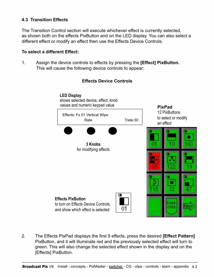
install - concepts - PixMaster - switcher - CG - clips - controls - team - appendix Broadcast Pix V8
4.3 Transition Effects
The Transition Control section will execute whichever effect is currently selected, as shown both on the effects PixButton and on the LED display. You can also select a different effect or modify an effect then use the Effects Device Controls.
To select a different Effect:
1. Assign the device controls to effects by pressing the [Effect] PixButton. This will cause the following device controls to appear:
3 Knobs for modifying effects
LED Display shows selected device, effect, knob values and numeric keypad value
Effects Device Controls
Effects PixButton to turn on Effects Device Controls, and show which effect is selected
PixPad 12 PixButtons to select or modify an effect
Effects: Fx 01 Vertical Wipe Rate Trate:30
2. The Effects PixPad displays the first 9 effects, press the desired [Effect Pattern] PixButton, and it will illuminate red and the previously selected effect will turn to green. This will also change the selected effect shown in the display and on the [Effects] PixButton.
4.3
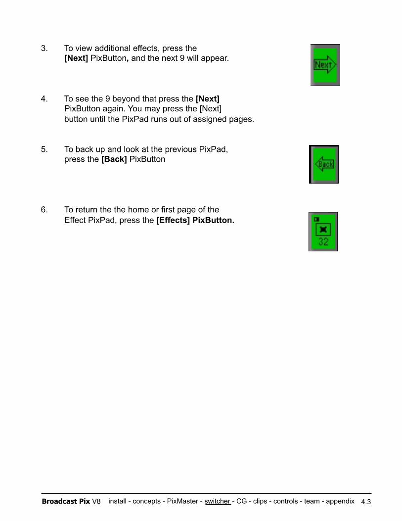
install - concepts - PixMaster - switcher - CG - clips - controls - team - appendix Broadcast Pix V8
3. To view additional effects, press the [Next] PixButton, and the next 9 will appear.
4. To see the 9 beyond that press the [Next] PixButton again. You may press the [Next] button until the PixPad runs out of assigned pages.
5. To back up and look at the previous PixPad, press the [Back] PixButton
6. To return the the home or first page of the Effect PixPad, press the [Effects] PixButton.
4.3
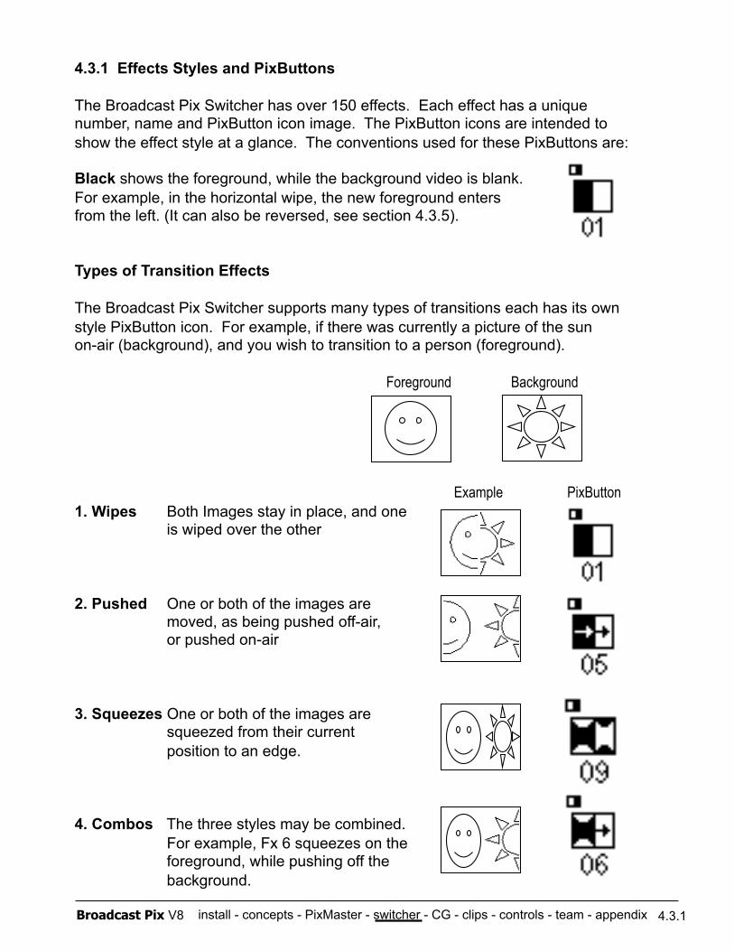
install - concepts - PixMaster - switcher - CG - clips - controls - team - appendix Broadcast Pix V8
4.3.1 Effects Styles and PixButtons
The Broadcast Pix Switcher has over 150 effects. Each effect has a unique number, name and PixButton icon image. The PixButton icons are intended to show the effect style at a glance. The conventions used for these PixButtons are:
Black shows the foreground, while the background video is blank. For example, in the horizontal wipe, the new foreground enters from the left. (It can also be reversed, see section 4.3.5).
Types of Transition Effects
The Broadcast Pix Switcher supports many types of transitions each has its own style PixButton icon. For example, if there was currently a picture of the sun on-air (background), and you wish to transition to a person (foreground).
Foreground Background
Example PixButton
1. Wipes Both Images stay in place, and one is wiped over the other
2. Pushed One or both of the images are moved, as being pushed off-air,
or pushed on-air
3. Squeezes One or both of the images are squeezed from their current position to an edge.
4. Combos The three styles may be combined. For example, Fx 6 squeezes on the foreground, while pushing off the background.
4.3.1
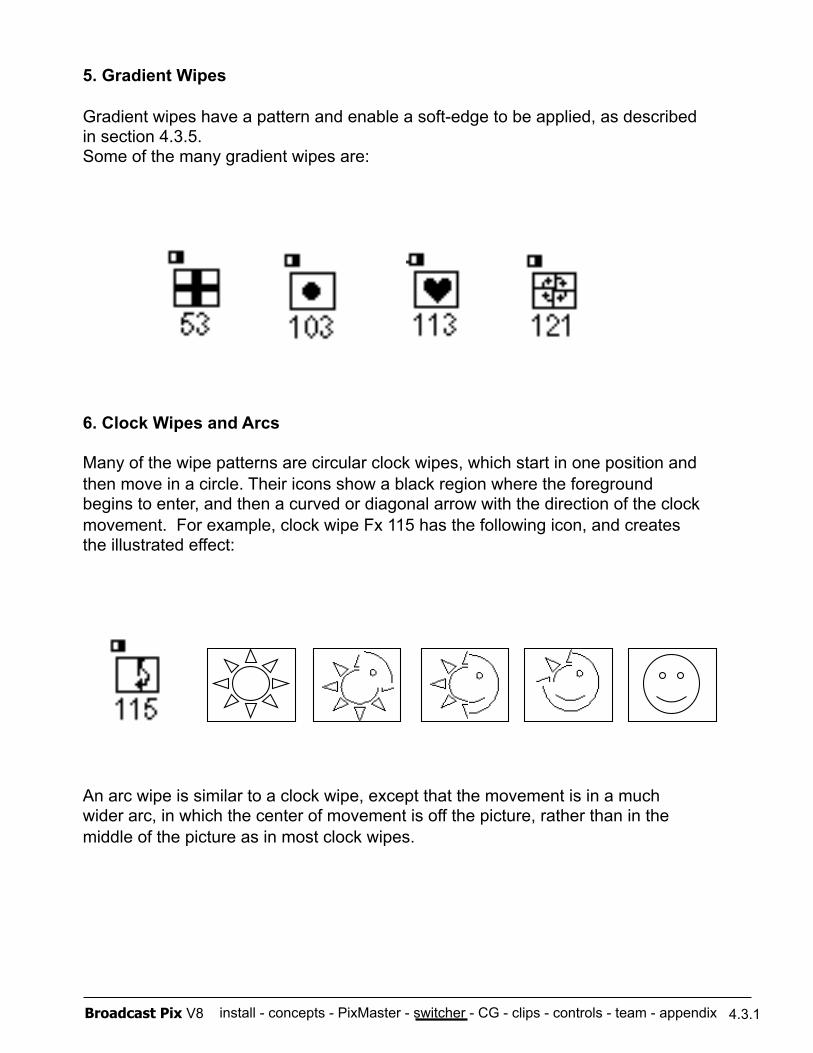
install - concepts - PixMaster - switcher - CG - clips - controls - team - appendix Broadcast Pix V8
5. Gradient Wipes
Gradient wipes have a pattern and enable a soft-edge to be applied, as described in section 4.3.5. Some of the many gradient wipes are:
6. Clock Wipes and Arcs
Many of the wipe patterns are circular clock wipes, which start in one position and then move in a circle. Their icons show a black region where the foreground begins to enter, and then a curved or diagonal arrow with the direction of the clock movement. For example, clock wipe Fx 115 has the following icon, and creates the illustrated effect:
An arc wipe is similar to a clock wipe, except that the movement is in a much wider arc, in which the center of movement is off the picture, rather than in the middle of the picture as in most clock wipes.
4.3.1
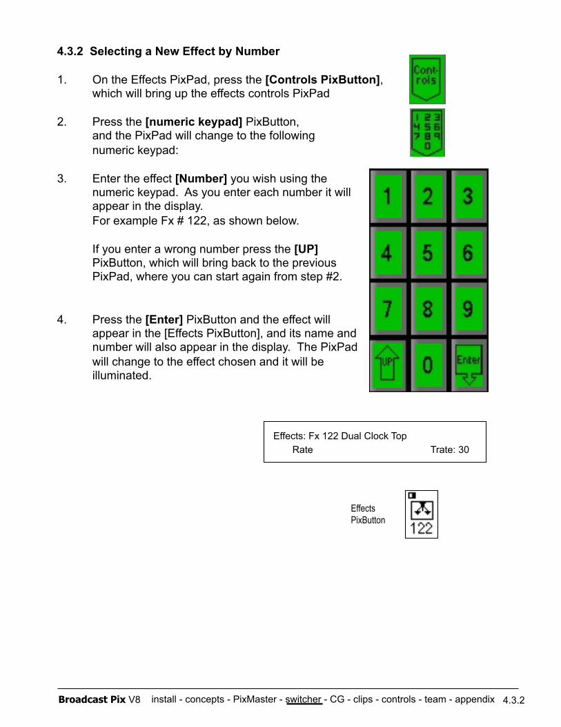
install - concepts - PixMaster - switcher - CG - clips - controls - team - appendix Broadcast Pix V8
4.3.2 Selecting a New Effect by Number
1. On the Effects PixPad, press the [Controls PixButton], which will bring up the effects controls PixPad
2. Press the [numeric keypad] PixButton, and the PixPad will change to the following
numeric keypad:
3. Enter the effect [Number] you wish using the numeric keypad. As you enter each number it will appear in the display. For example Fx # 122, as shown below.
If you enter a wrong number press the [UP] PixButton, which will bring back to the previous PixPad, where you can start again from step #2.
4. Press the [Enter] PixButton and the effect will appear in the [Effects PixButton], and its name and number will also appear in the display. The PixPad will change to the effect chosen and it will be illuminated.
Effects: Fx 122 Dual Clock Top Rate Trate: 30
Effects PixButton
4.3.2
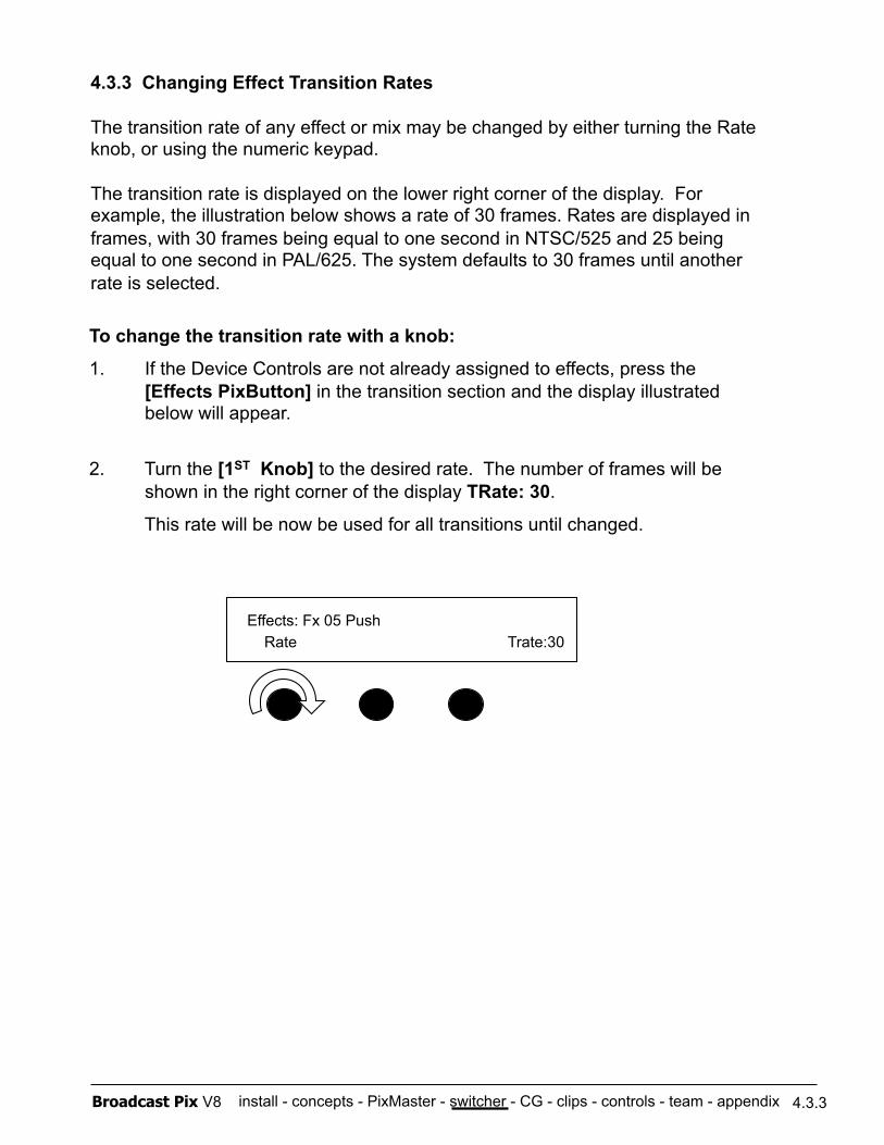
install - concepts - PixMaster - switcher - CG - clips - controls - team - appendix Broadcast Pix V8
4.3.3 Changing Effect Transition Rates
The transition rate of any effect or mix may be changed by either turning the Rate knob, or using the numeric keypad.
The transition rate is displayed on the lower right corner of the display. For example, the illustration below shows a rate of 30 frames. Rates are displayed in frames, with 30 frames being equal to one second in NTSC/525 and 25 being equal to one second in PAL/625. The system defaults to 30 frames until another rate is selected.
To change the transition rate with a knob:
1. If the Device Controls are not already assigned to effects, press the [Effects PixButton] in the transition section and the display illustrated below will appear.
2. Turn the [1ST Knob] to the desired rate. The number of frames will be shown in the right corner of the display TRate: 30.
This rate will be now be used for all transitions until changed.
Effects: Fx 05 Push Rate Trate:30
4.3.3
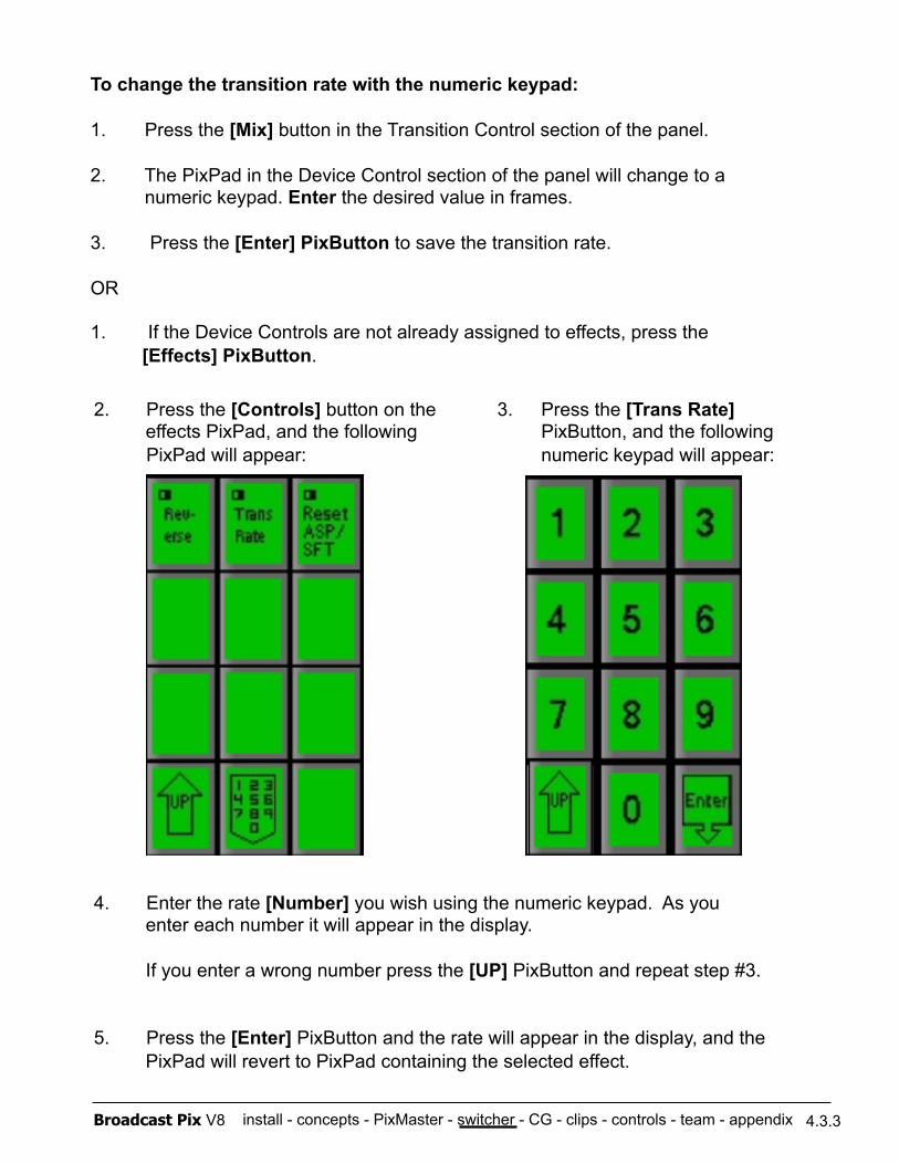
install - concepts - PixMaster - switcher - CG - clips - controls - team - appendix Broadcast Pix V8
To change the transition rate with the numeric keypad:
1. Press the [Mix] button in the Transition Control section of the panel.
2. The PixPad in the Device Control section of the panel will change to a numeric keypad. Enter the desired value in frames.
3. Press the [Enter] PixButton to save the transition rate.
OR
1. If the Device Controls are not already assigned to effects, press the [Effects] PixButton.
3. Press the [Trans Rate] PixButton, and the following numeric keypad will appear:
4. Enter the rate [Number] you wish using the numeric keypad. As you enter each number it will appear in the display.
If you enter a wrong number press the [UP] PixButton and repeat step #3.
5. Press the [Enter] PixButton and the rate will appear in the display, and the PixPad will revert to PixPad containing the selected effect.
2. Press the [Controls] button on the effects PixPad, and the following PixPad will appear:
4.3.3
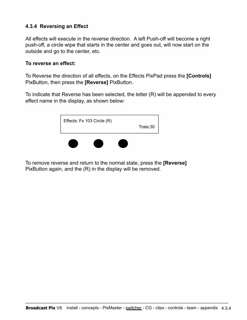
install - concepts - PixMaster - switcher - CG - clips - controls - team - appendix Broadcast Pix V8 4.3.4
4.3.4 Reversing an Effect
All effects will execute in the reverse direction. A left Push-off will become a right push-off, a circle wipe that starts in the center and goes out, will now start on the outside and go to the center, etc.
To reverse an effect:
To Reverse the direction of all effects, on the Effects PixPad press the [Controls] PixButton, then press the [Reverse] PixButton.
To indicate that Reverse has been selected, the letter (R) will be appended to every effect name in the display, as shown below:
To remove reverse and return to the normal state, press the [Reverse] PixButton again, and the (R) in the display will be removed.
Effects: Fx 103 Circle (R) Trate:30
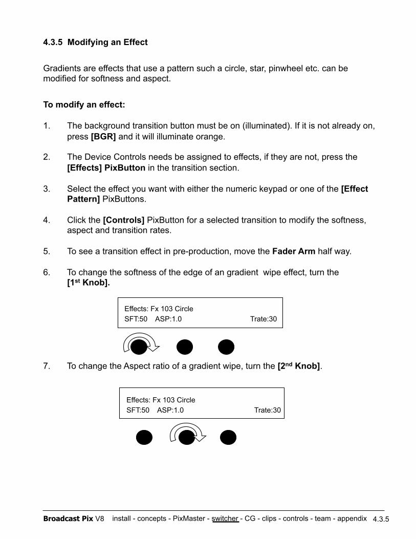
install - concepts - PixMaster - switcher - CG - clips - controls - team - appendix Broadcast Pix V8
4.3.5 Modifying an Effect
Gradients are effects that use a pattern such a circle, star, pinwheel etc. can be modified for softness and aspect.
To modify an effect:
1. The background transition button must be on (illuminated). If it is not already on, press [BGR] and it will illuminate orange.
2. The Device Controls needs be assigned to effects, if they are not, press the [Effects] PixButton in the transition section.
3. Select the effect you want with either the numeric keypad or one of the [Effect Pattern] PixButtons.
4. Click the [Controls] PixButton for a selected transition to modify the softness, aspect and transition rates.
5. To see a transition effect in pre-production, move the Fader Arm half way.
6. To change the softness of the edge of an gradient wipe effect, turn the [1st Knob].
7. To change the Aspect ratio of a gradient wipe, turn the [2nd Knob].
4.3.5
Effects: Fx 103 Circle SFT:50 ASP:1.0 Trate:30
Effects: Fx 103 Circle SFT:50 ASP:1.0 Trate:30
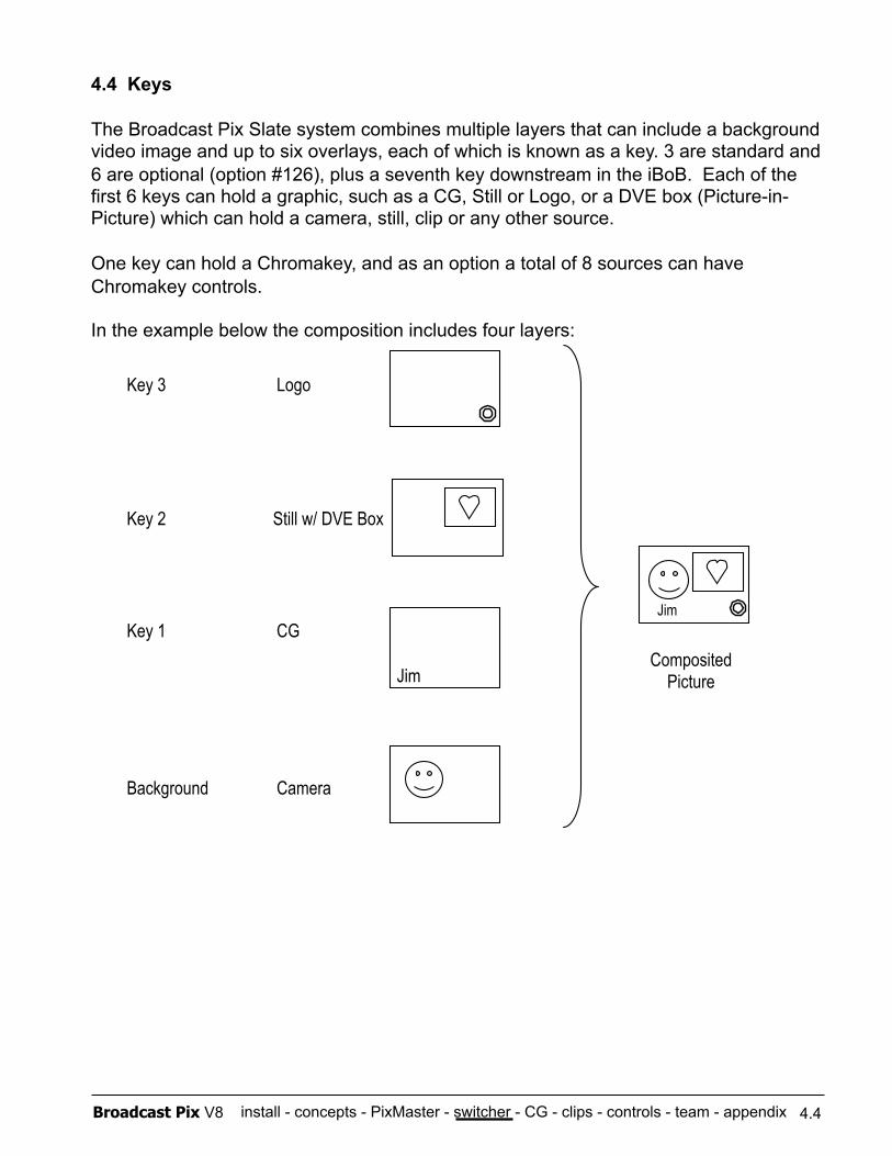
install - concepts - PixMaster - switcher - CG - clips - controls - team - appendix Broadcast Pix V8
4.4 Keys
The Broadcast Pix Slate system combines multiple layers that can include a background video image and up to six overlays, each of which is known as a key. 3 are standard and 6 are optional (option #126), plus a seventh key downstream in the iBoB. Each of the first 6 keys can hold a graphic, such as a CG, Still or Logo, or a DVE box (Picture-in-Picture) which can hold a camera, still, clip or any other source.
One key can hold a Chromakey, and as an option a total of 8 sources can have Chromakey controls.
In the example below the composition includes four layers:
Composited Picture
Key 3 Logo
Key 2 Still w/ DVE Box
Key 1 CG
Background Camera
Jim
Jim
4.4
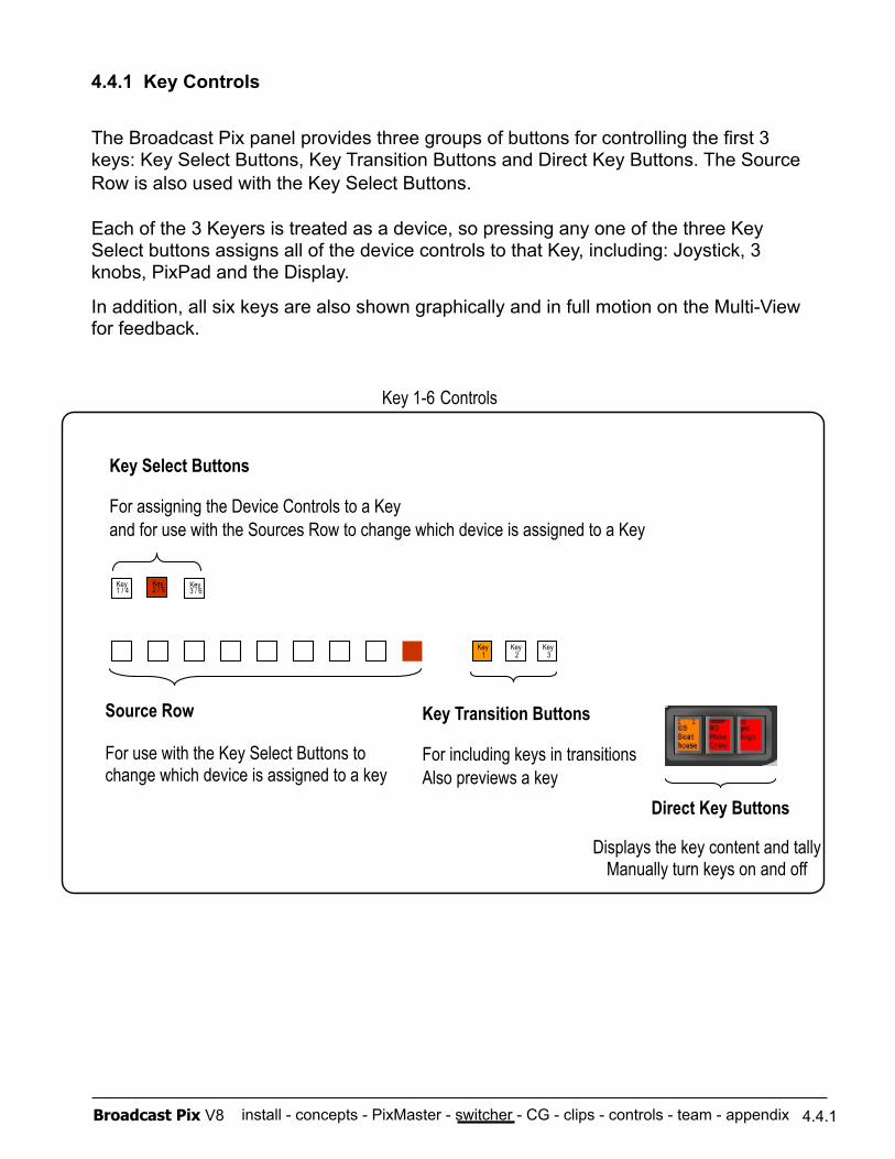
install - concepts - PixMaster - switcher - CG - clips - controls - team - appendix Broadcast Pix V8
4.4.1 Key Controls
The Broadcast Pix panel provides three groups of buttons for controlling the first 3 keys: Key Select Buttons, Key Transition Buttons and Direct Key Buttons. The Source Row is also used with the Key Select Buttons.
Each of the 3 Keyers is treated as a device, so pressing any one of the three Key Select buttons assigns all of the device controls to that Key, including: Joystick, 3 knobs, PixPad and the Display.
In addition, all six keys are also shown graphically and in full motion on the Multi-View for feedback.
Key 1
Key 2
Key 3
Key 3 / 6
Key 1 / 4
Key 2 / 5
Direct Key Buttons
Key Transition Buttons
For including keys in transitions Also previews a key
Source Row
For use with the Key Select Buttons to change which device is assigned to a key
Key Select Buttons
For assigning the Device Controls to a Key and for use with the Sources Row to change which device is assigned to a Key
Key 1-6 Controls
4.4.1
Displays the key content and tally Manually turn keys on and off
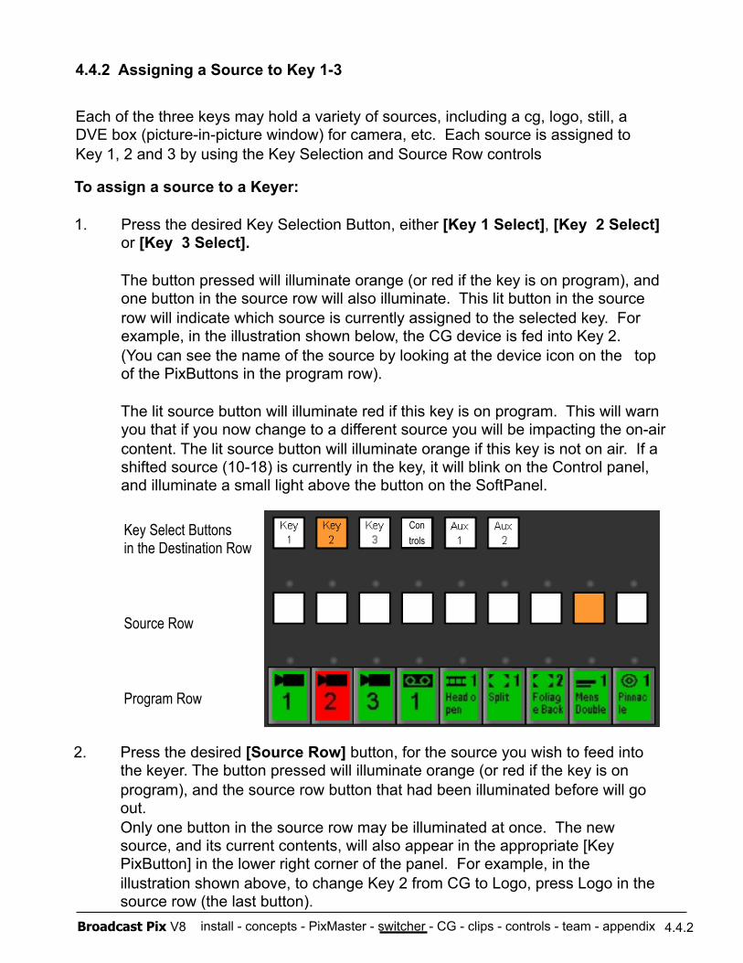
install - concepts - PixMaster - switcher - CG - clips - controls - team - appendix Broadcast Pix V8
To assign a source to a Keyer:
1. Press the desired Key Selection Button, either [Key 1 Select], [Key 2 Select] or [Key 3 Select].
The button pressed will illuminate orange (or red if the key is on program), and one button in the source row will also illuminate. This lit button in the source row will indicate which source is currently assigned to the selected key. For example, in the illustration shown below, the CG device is fed into Key 2. (You can see the name of the source by looking at the device icon on the top of the PixButtons in the program row).
The lit source button will illuminate red if this key is on program. This will warn you that if you now change to a different source you will be impacting the on-air content. The lit source button will illuminate orange if this key is not on air. If a shifted source (10-18) is currently in the key, it will blink on the Control panel, and illuminate a small light above the button on the SoftPanel.
4.4.2 Assigning a Source to Key 1-3
Each of the three keys may hold a variety of sources, including a cg, logo, still, a DVE box (picture-in-picture window) for camera, etc. Each source is assigned to Key 1, 2 and 3 by using the Key Selection and Source Row controls
2. Press the desired [Source Row] button, for the source you wish to feed into the keyer. The button pressed will illuminate orange (or red if the key is on program), and the source row button that had been illuminated before will go out. Only one button in the source row may be illuminated at once. The new source, and its current contents, will also appear in the appropriate [Key PixButton] in the lower right corner of the panel. For example, in the illustration shown above, to change Key 2 from CG to Logo, press Logo in the source row (the last button).
Key Select Buttons in the Destination Row
Source Row
Program Row
4.4.2
Con trols
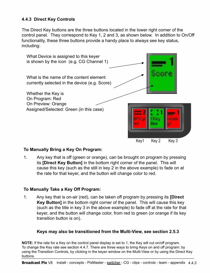
install - concepts - PixMaster - switcher - CG - clips - controls - team - appendix Broadcast Pix V8
4.4.3 Direct Key Controls
The Direct Key buttons are the three buttons located in the lower right corner of the control panel. They correspond to Key 1, 2 and 3, as shown below. In addition to On/Off functionality, these three buttons provide a handy place to always see key status, including:
What Device is assigned to this keyer is shown by the icon (e.g. CG Channel 1)
What is the name of the content element currently selected in the device (e.g. Score)
Whether the Key is On Program: Red On Preview: Orange Assigned/Selected: Green (in this case)
To Manually Bring a Key On Program:
1. Any key that is off (green or orange), can be brought on program by pressing its [Direct Key Button] in the bottom right corner of the panel. This will cause this key (such as the still in key 2 in the above example) to fade on at the rate for that keyer, and the button will change color to red.
To Manually Take a Key Off Program:
1. Any key that is on-air (red), can be taken off program by pressing its [Direct Key Button] in the bottom right corner of the panel. This will cause this key (such as the title in key 3 in the above example) to fade off at the rate for that keyer, and the button will change color, from red to green (or orange if its key transition button is on).
Keys may also be transitioned from the Multi-View, see section 2.5.3
4.4.3
Key1 Key 2 Key 3
NOTE: If the rate for a Key on the control panel display is set to 1, the Key will cut on/off program. To change the Key rate see section 4.4.7. There are three ways to bring Keys on and off program: by using the Transition Controls, by clicking in the keyer window on the Multi-View or by using the Direct Key buttons.
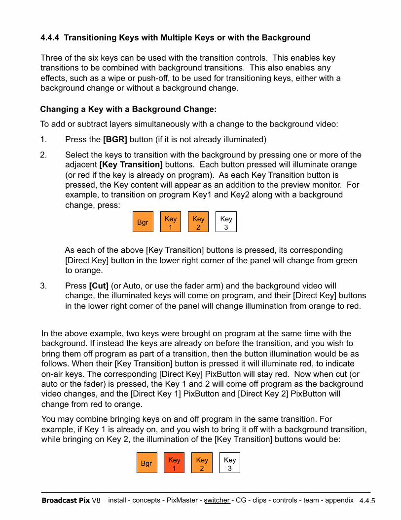
install - concepts - PixMaster - switcher - CG - clips - controls - team - appendix Broadcast Pix V8
4.4.4 Transitioning Keys with Multiple Keys or with the Background
Three of the six keys can be used with the transition controls. This enables key transitions to be combined with background transitions. This also enables any effects, such as a wipe or push-off, to be used for transitioning keys, either with a background change or without a background change.
Key 1 Bgr Key
2 Key 3
Changing a Key with a Background Change:
To add or subtract layers simultaneously with a change to the background video:
1. Press the [BGR] button (if it is not already illuminated)
2. Select the keys to transition with the background by pressing one or more of the adjacent [Key Transition] buttons. Each button pressed will illuminate orange (or red if the key is already on program). As each Key Transition button is pressed, the Key content will appear as an addition to the preview monitor. For example, to transition on program Key1 and Key2 along with a background change, press:
As each of the above [Key Transition] buttons is pressed, its corresponding [Direct Key] button in the lower right corner of the panel will change from green to orange.
3. Press [Cut] (or Auto, or use the fader arm) and the background video will change, the illuminated keys will come on program, and their [Direct Key] buttons in the lower right corner of the panel will change illumination from orange to red.
In the above example, two keys were brought on program at the same time with the background. If instead the keys are already on before the transition, and you wish to bring them off program as part of a transition, then the button illumination would be as follows. When their [Key Transition] button is pressed it will illuminate red, to indicate on-air keys. The corresponding [Direct Key] PixButton will stay red. Now when cut (or auto or the fader) is pressed, the Key 1 and 2 will come off program as the background video changes, and the [Direct Key 1] PixButton and [Direct Key 2] PixButton will change from red to orange.
You may combine bringing keys on and off program in the same transition. For example, if Key 1 is already on, and you wish to bring it off with a background transition, while bringing on Key 2, the illumination of the [Key Transition] buttons would be:
Key 1 Bgr Key
2 Key 3
4.4.5
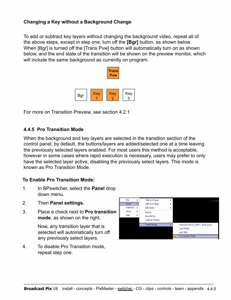
install - concepts - PixMaster - switcher - CG - clips - controls - team - appendix Broadcast Pix V8
Changing a Key without a Background Change
To add or subtract key layers without changing the background video, repeat all of the above steps, except in step one, turn off the [Bgr] button, as shown below. When [Bgr] is turned off the [Trans Pvw] button will automatically turn on as shown below, and the end state of the transition will be shown on the preview monitor, which will include the same background as currently on program.
For more on Transition Preview, see section 4.2.1
4.4.5 Pro Transition Mode
When the background and key layers are selected in the transition section of the control panel, by default, the buttons/layers are added/selected one at a time leaving the previously selected layers enabled. For most users this method is acceptable, however in some cases where rapid execution is necessary, users may prefer to only have the selected layer active, disabling the previously select layers. This mode is known as Pro Transition Mode.
Key 1 Bgr Key
2 Key 3
Trans Pvw
4.4.5
To Enable Pro Transition Mode:
1. In BPswitcher, select the Panel drop down menu.
2. Then Panel settings.
3. Place a check next to Pro transition mode, as shown on the right.
Now, any transition layer that is selected will automatically turn off any previously select layers.
4. To disable Pro Transition mode, repeat step one.
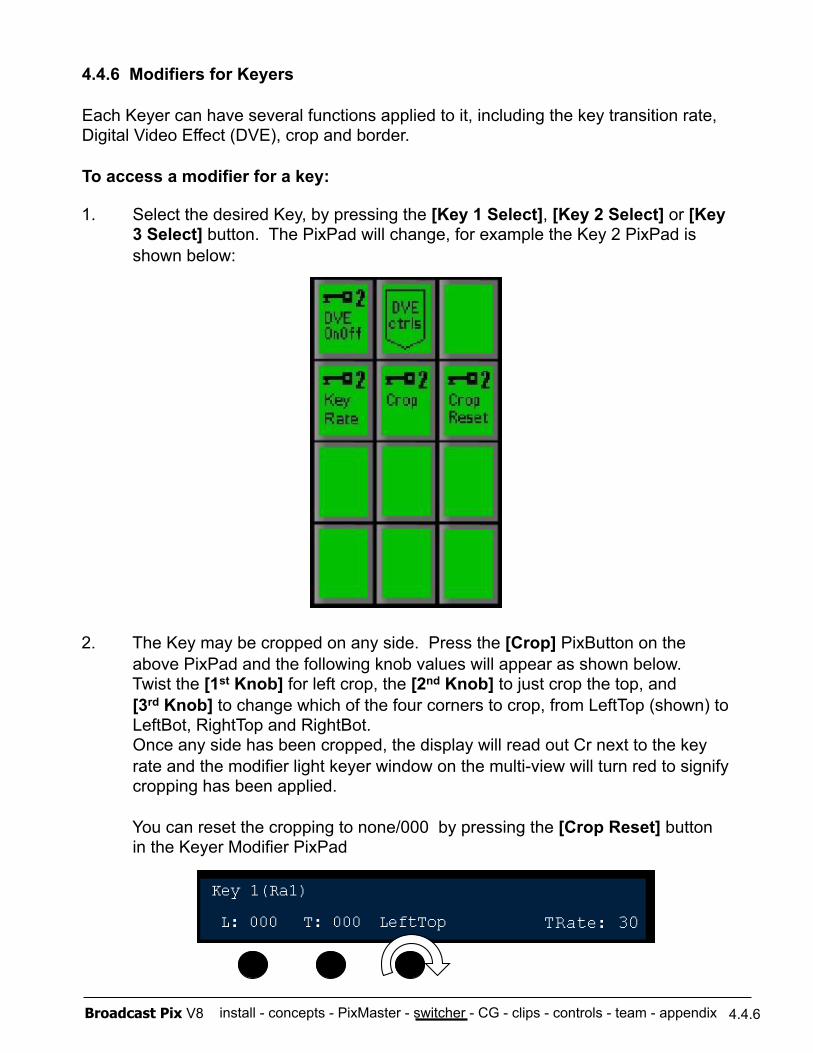
install - concepts - PixMaster - switcher - CG - clips - controls - team - appendix Broadcast Pix V8
1. Select the desired Key, by pressing the [Key 1 Select], [Key 2 Select] or [Key 3 Select] button. The PixPad will change, for example the Key 2 PixPad is shown below:
2. The Key may be cropped on any side. Press the [Crop] PixButton on the above PixPad and the following knob values will appear as shown below. Twist the [1st Knob] for left crop, the [2nd Knob] to just crop the top, and [3rd Knob] to change which of the four corners to crop, from LeftTop (shown) to LeftBot, RightTop and RightBot. Once any side has been cropped, the display will read out Cr next to the key rate and the modifier light keyer window on the multi-view will turn red to signify cropping has been applied.
You can reset the cropping to none/000 by pressing the [Crop Reset] button in the Keyer Modifier PixPad
4.4.6 Modifiers for Keyers
Each Keyer can have several functions applied to it, including the key transition rate, Digital Video Effect (DVE), crop and border.
To access a modifier for a key:
4.4.6
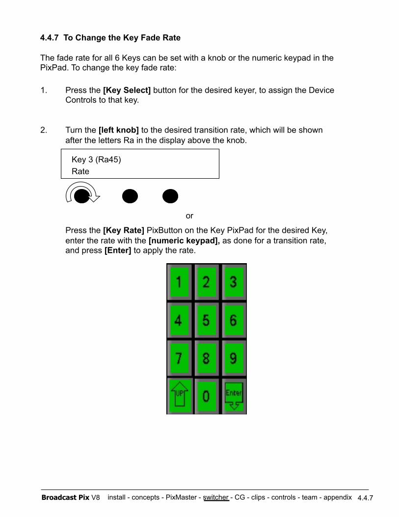
install - concepts - PixMaster - switcher - CG - clips - controls - team - appendix Broadcast Pix V8
4.4.7 To Change the Key Fade Rate
The fade rate for all 6 Keys can be set with a knob or the numeric keypad in the PixPad. To change the key fade rate:
1. Press the [Key Select] button for the desired keyer, to assign the Device Controls to that key.
2. Turn the [left knob] to the desired transition rate, which will be shown after the letters Ra in the display above the knob.
or
Press the [Key Rate] PixButton on the Key PixPad for the desired Key, enter the rate with the [numeric keypad], as done for a transition rate, and press [Enter] to apply the rate.
Key 3 (Ra45) Rate
4.4.7
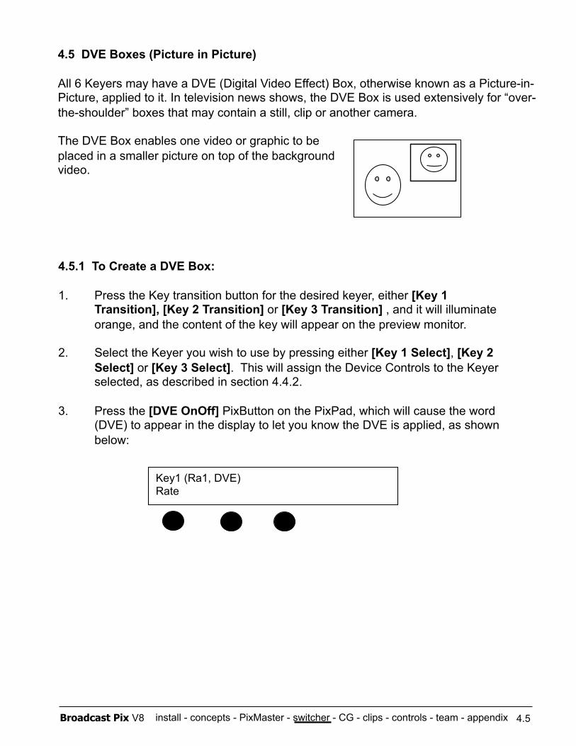
install - concepts - PixMaster - switcher - CG - clips - controls - team - appendix Broadcast Pix V8
4.5.1 To Create a DVE Box:
1. Press the Key transition button for the desired keyer, either [Key 1 Transition], [Key 2 Transition] or [Key 3 Transition] , and it will illuminate orange, and the content of the key will appear on the preview monitor.
2. Select the Keyer you wish to use by pressing either [Key 1 Select], [Key 2 Select] or [Key 3 Select]. This will assign the Device Controls to the Keyer selected, as described in section 4.4.2.
3. Press the [DVE OnOff] PixButton on the PixPad, which will cause the word (DVE) to appear in the display to let you know the DVE is applied, as shown below:
Key1 (Ra1, DVE) Rate
4.5 DVE Boxes (Picture in Picture)
All 6 Keyers may have a DVE (Digital Video Effect) Box, otherwise known as a Picture-in-Picture, applied to it. In television news shows, the DVE Box is used extensively for “over-the-shoulder” boxes that may contain a still, clip or another camera.
The DVE Box enables one video or graphic to be placed in a smaller picture on top of the background video.
4.5
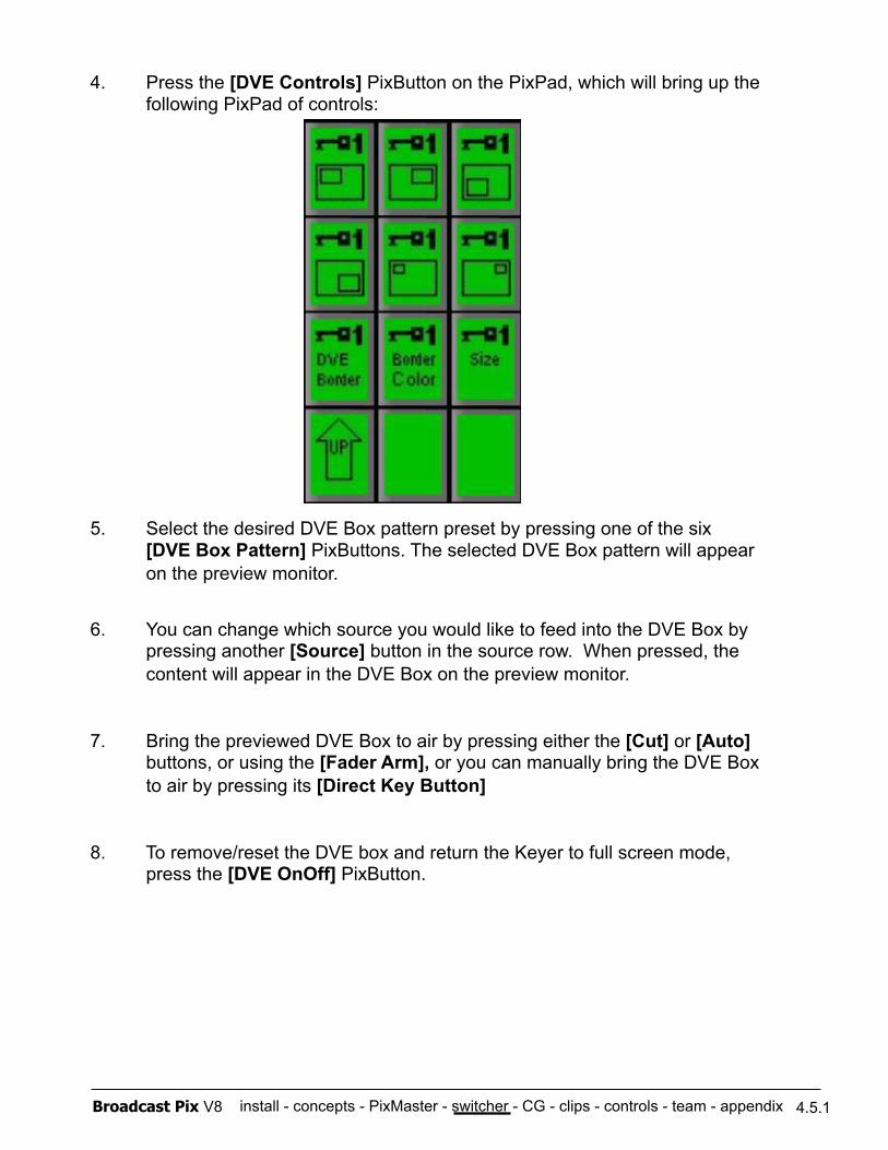
install - concepts - PixMaster - switcher - CG - clips - controls - team - appendix Broadcast Pix V8
4. Press the [DVE Controls] PixButton on the PixPad, which will bring up the following PixPad of controls:
5. Select the desired DVE Box pattern preset by pressing one of the six [DVE Box Pattern] PixButtons. The selected DVE Box pattern will appear on the preview monitor.
6. You can change which source you would like to feed into the DVE Box by pressing another [Source] button in the source row. When pressed, the content will appear in the DVE Box on the preview monitor.
7. Bring the previewed DVE Box to air by pressing either the [Cut] or [Auto] buttons, or using the [Fader Arm], or you can manually bring the DVE Box to air by pressing its [Direct Key Button]
8. To remove/reset the DVE box and return the Keyer to full screen mode, press the [DVE OnOff] PixButton.
4.5.1
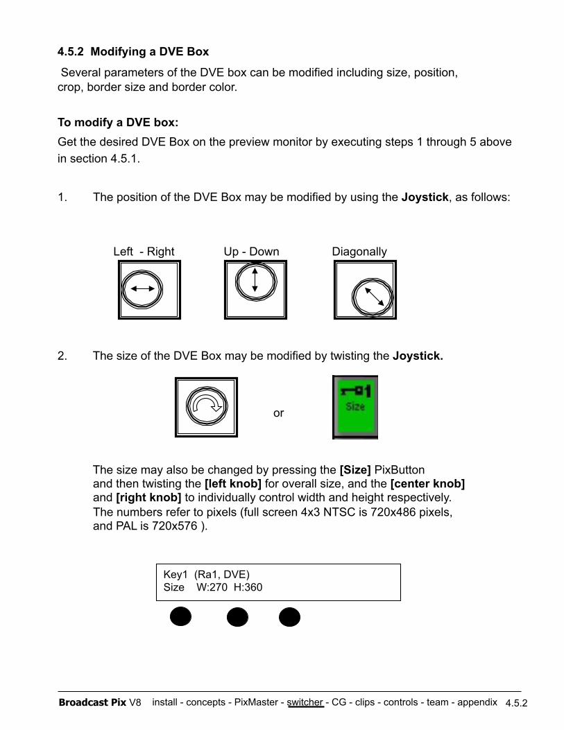
install - concepts - PixMaster - switcher - CG - clips - controls - team - appendix Broadcast Pix V8
Left - Right Up - Down Diagonally
4.5.2 Modifying a DVE Box
Several parameters of the DVE box can be modified including size, position, crop, border size and border color.
To modify a DVE box:
Key1 (Ra1, DVE) Size W:270 H:360
Get the desired DVE Box on the preview monitor by executing steps 1 through 5 above in section 4.5.1.
1. The position of the DVE Box may be modified by using the Joystick, as follows:
2. The size of the DVE Box may be modified by twisting the Joystick.
or
The size may also be changed by pressing the [Size] PixButton and then twisting the [left knob] for overall size, and the [center knob] and [right knob] to individually control width and height respectively. The numbers refer to pixels (full screen 4x3 NTSC is 720x486 pixels, and PAL is 720x576 ).
4.5.2
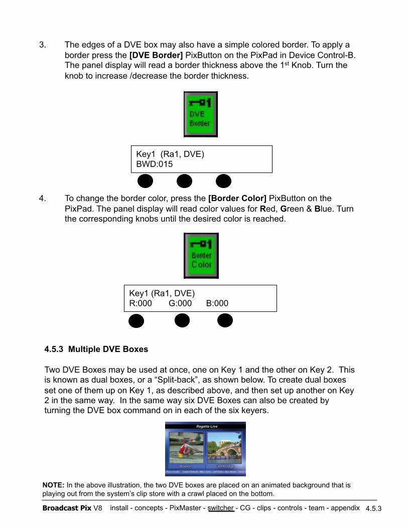
install - concepts - PixMaster - switcher - CG - clips - controls - team - appendix Broadcast Pix V8
3. The edges of a DVE box may also have a simple colored border. To apply a border press the [DVE Border] PixButton on the PixPad in Device Control-B. The panel display will read a border thickness above the 1st Knob. Turn the knob to increase /decrease the border thickness.
4. To change the border color, press the [Border Color] PixButton on the PixPad. The panel display will read color values for Red, Green & Blue. Turn the corresponding knobs until the desired color is reached.
4.5.3
4.5.3 Multiple DVE Boxes
Two DVE Boxes may be used at once, one on Key 1 and the other on Key 2. This is known as dual boxes, or a “Split-back”, as shown below. To create dual boxes set one of them up on Key 1, as described above, and then set up another on Key 2 in the same way. In the same way six DVE Boxes can also be created by turning the DVE box command on in each of the six keyers.
NOTE: In the above illustration, the two DVE boxes are placed on an animated background that is playing out from the system’s clip store with a crawl placed on the bottom.
Key1 (Ra1, DVE) BWD:015
Key1 (Ra1, DVE) R:000 G:000 B:000
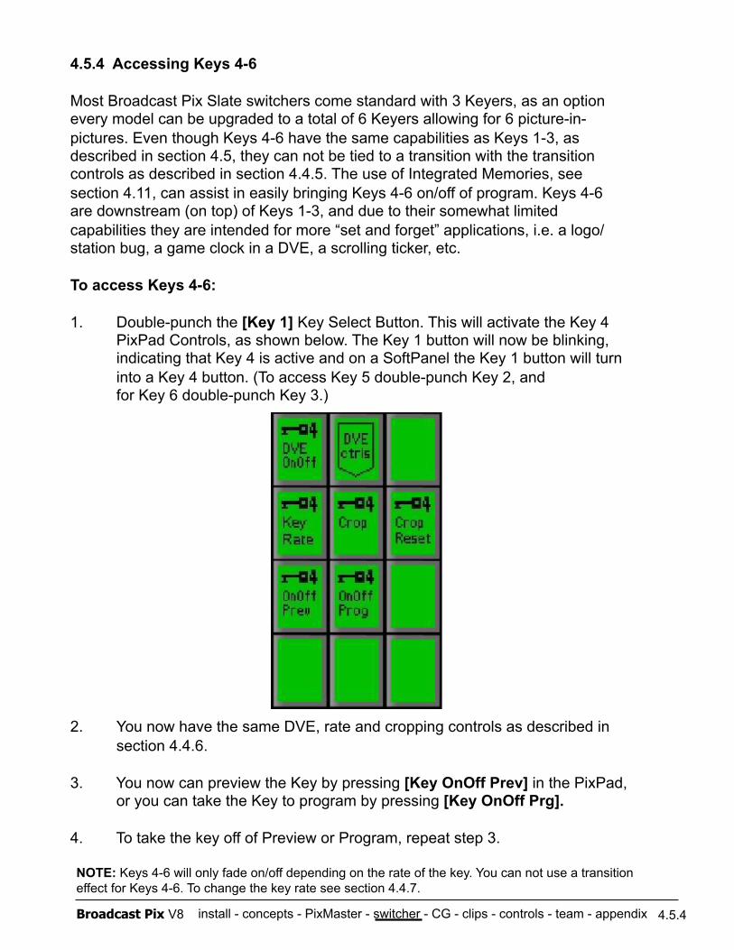
install - concepts - PixMaster - switcher - CG - clips - controls - team - appendix Broadcast Pix V8 4.5.4
4.5.4 Accessing Keys 4-6
Most Broadcast Pix Slate switchers come standard with 3 Keyers, as an option every model can be upgraded to a total of 6 Keyers allowing for 6 picture-in- pictures. Even though Keys 4-6 have the same capabilities as Keys 1-3, as described in section 4.5, they can not be tied to a transition with the transition controls as described in section 4.4.5. The use of Integrated Memories, see section 4.11, can assist in easily bringing Keys 4-6 on/off of program. Keys 4-6 are downstream (on top) of Keys 1-3, and due to their somewhat limited capabilities they are intended for more “set and forget” applications, i.e. a logo/ station bug, a game clock in a DVE, a scrolling ticker, etc.
To access Keys 4-6:
1. Double-punch the [Key 1] Key Select Button. This will activate the Key 4 PixPad Controls, as shown below. The Key 1 button will now be blinking, indicating that Key 4 is active and on a SoftPanel the Key 1 button will turn into a Key 4 button. (To access Key 5 double-punch Key 2, and for Key 6 double-punch Key 3.)
2. You now have the same DVE, rate and cropping controls as described in section 4.4.6.
3. You now can preview the Key by pressing [Key OnOff Prev] in the PixPad, or you can take the Key to program by pressing [Key OnOff Prg].
4. To take the key off of Preview or Program, repeat step 3.
NOTE: Keys 4-6 will only fade on/off depending on the rate of the key. You can not use a transition effect for Keys 4-6. To change the key rate see section 4.4.7.
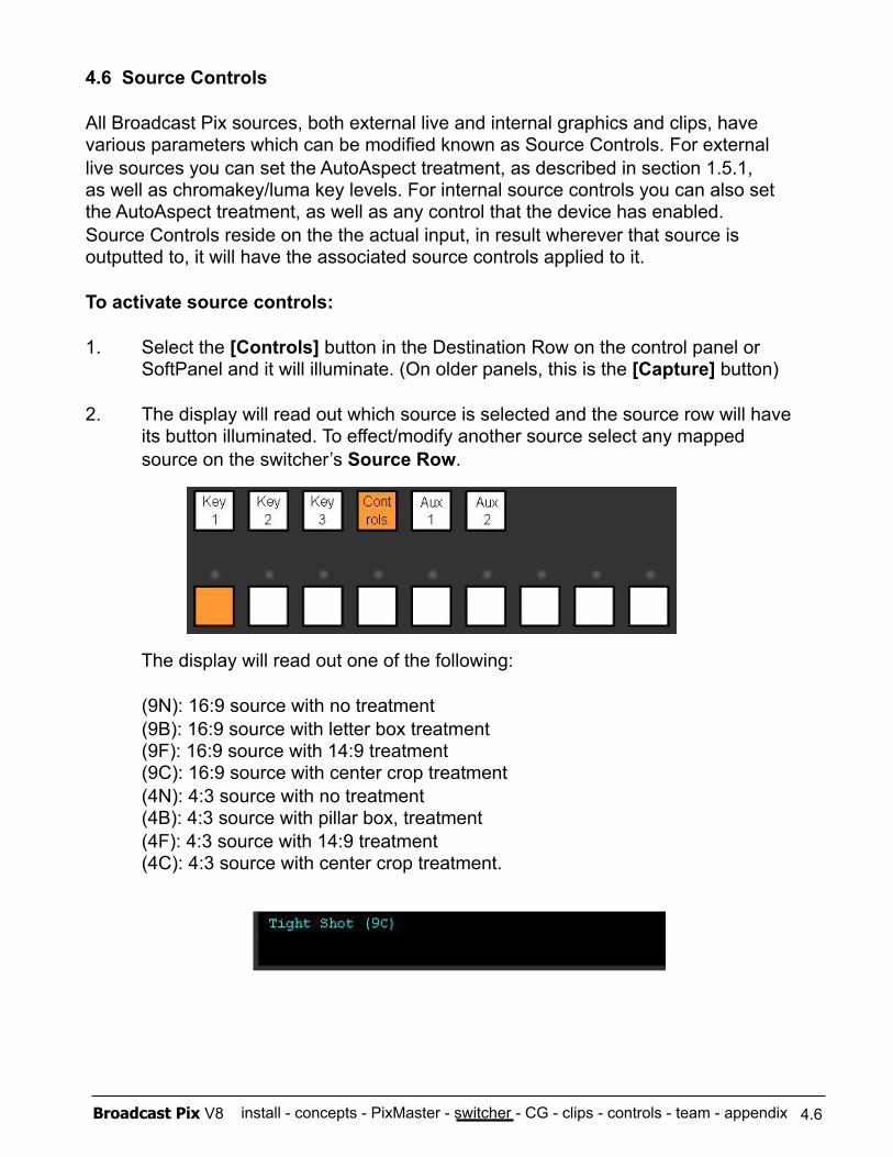
install - concepts - PixMaster - switcher - CG - clips - controls - team - appendix Broadcast Pix V8
4.6 Source Controls
All Broadcast Pix sources, both external live and internal graphics and clips, have various parameters which can be modified known as Source Controls. For external live sources you can set the AutoAspect treatment, as described in section 1.5.1, as well as chromakey/luma key levels. For internal source controls you can also set the AutoAspect treatment, as well as any control that the device has enabled. Source Controls reside on the the actual input, in result wherever that source is outputted to, it will have the associated source controls applied to it.
To activate source controls:
1. Select the [Controls] button in the Destination Row on the control panel or SoftPanel and it will illuminate. (On older panels, this is the [Capture] button)
2. The display will read out which source is selected and the source row will have its button illuminated. To effect/modify another source select any mapped source on the switcher’s Source Row.
The display will read out one of the following:
(9N): 16:9 source with no treatment (9B): 16:9 source with letter box treatment (9F): 16:9 source with 14:9 treatment
(9C): 16:9 source with center crop treatment (4N): 4:3 source with no treatment (4B): 4:3 source with pillar box, treatment (4F): 4:3 source with 14:9 treatment (4C): 4:3 source with center crop treatment.
4.6
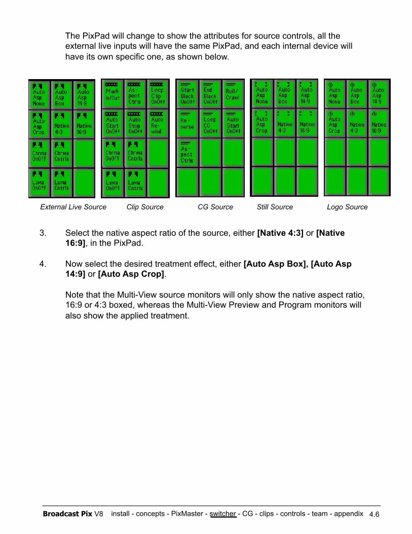
install - concepts - PixMaster - switcher - CG - clips - controls - team - appendix Broadcast Pix V8
The PixPad will change to show the attributes for source controls, all the external live inputs will have the same PixPad, and each internal device will have its own specific one, as shown below.
3. Select the native aspect ratio of the source, either [Native 4:3] or [Native 16:9], in the PixPad.
4. Now select the desired treatment effect, either [Auto Asp Box], [Auto Asp 14:9] or [Auto Asp Crop].
Note that the Multi-View source monitors will only show the native aspect ratio, 16:9 or 4:3 boxed, whereas the Multi-View Preview and Program monitors will also show the applied treatment.
4.6
External Live Source Clip Source CG Source Still Source Logo Source
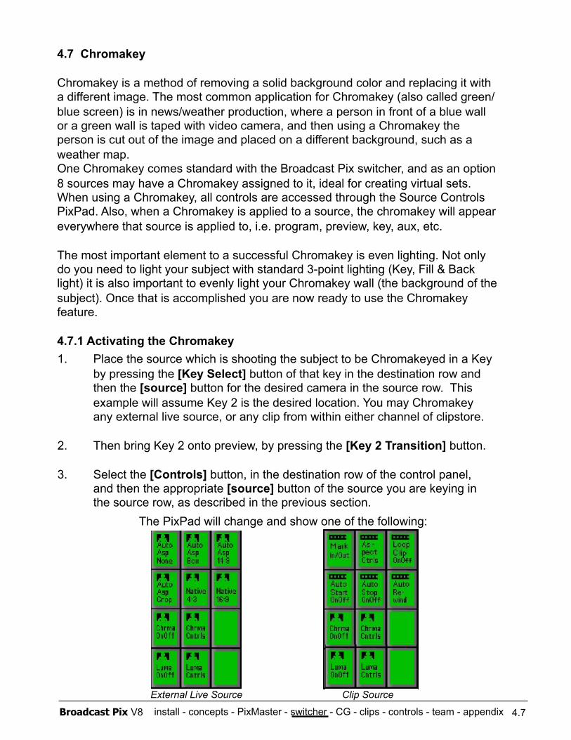
install - concepts - PixMaster - switcher - CG - clips - controls - team - appendix Broadcast Pix V8
4.7 Chromakey
Chromakey is a method of removing a solid background color and replacing it with a different image. The most common application for Chromakey (also called green/blue screen) is in news/weather production, where a person in front of a blue wall or a green wall is taped with video camera, and then using a Chromakey the person is cut out of the image and placed on a different background, such as a weather map. One Chromakey comes standard with the Broadcast Pix switcher, and as an option 8 sources may have a Chromakey assigned to it, ideal for creating virtual sets. When using a Chromakey, all controls are accessed through the Source Controls PixPad. Also, when a Chromakey is applied to a source, the chromakey will appear everywhere that source is applied to, i.e. program, preview, key, aux, etc.
The most important element to a successful Chromakey is even lighting. Not only do you need to light your subject with standard 3-point lighting (Key, Fill & Back light) it is also important to evenly light your Chromakey wall (the background of the subject). Once that is accomplished you are now ready to use the Chromakey feature.
4.7.1 Activating the Chromakey 1. Place the source which is shooting the subject to be Chromakeyed in a Key
by pressing the [Key Select] button of that key in the destination row and then the [source] button for the desired camera in the source row. This example will assume Key 2 is the desired location. You may Chromakey any external live source, or any clip from within either channel of clipstore.
2. Then bring Key 2 onto preview, by pressing the [Key 2 Transition] button.
3. Select the [Controls] button, in the destination row of the control panel, and then the appropriate [source] button of the source you are keying in the source row, as described in the previous section. The PixPad will change and show one of the following:
4.7
External Live Source Clip Source
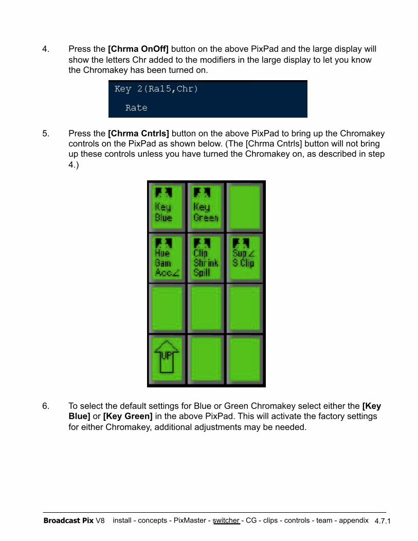
install - concepts - PixMaster - switcher - CG - clips - controls - team - appendix Broadcast Pix V8
4. Press the [Chrma OnOff] button on the above PixPad and the large display will show the letters Chr added to the modifiers in the large display to let you know the Chromakey has been turned on.
5. Press the [Chrma Cntrls] button on the above PixPad to bring up the Chromakey controls on the PixPad as shown below. (The [Chrma Cntrls] button will not bring up these controls unless you have turned the Chromakey on, as described in step 4.)
6. To select the default settings for Blue or Green Chromakey select either the [Key Blue] or [Key Green] in the above PixPad. This will activate the factory settings for either Chromakey, additional adjustments may be needed.
4.7.1
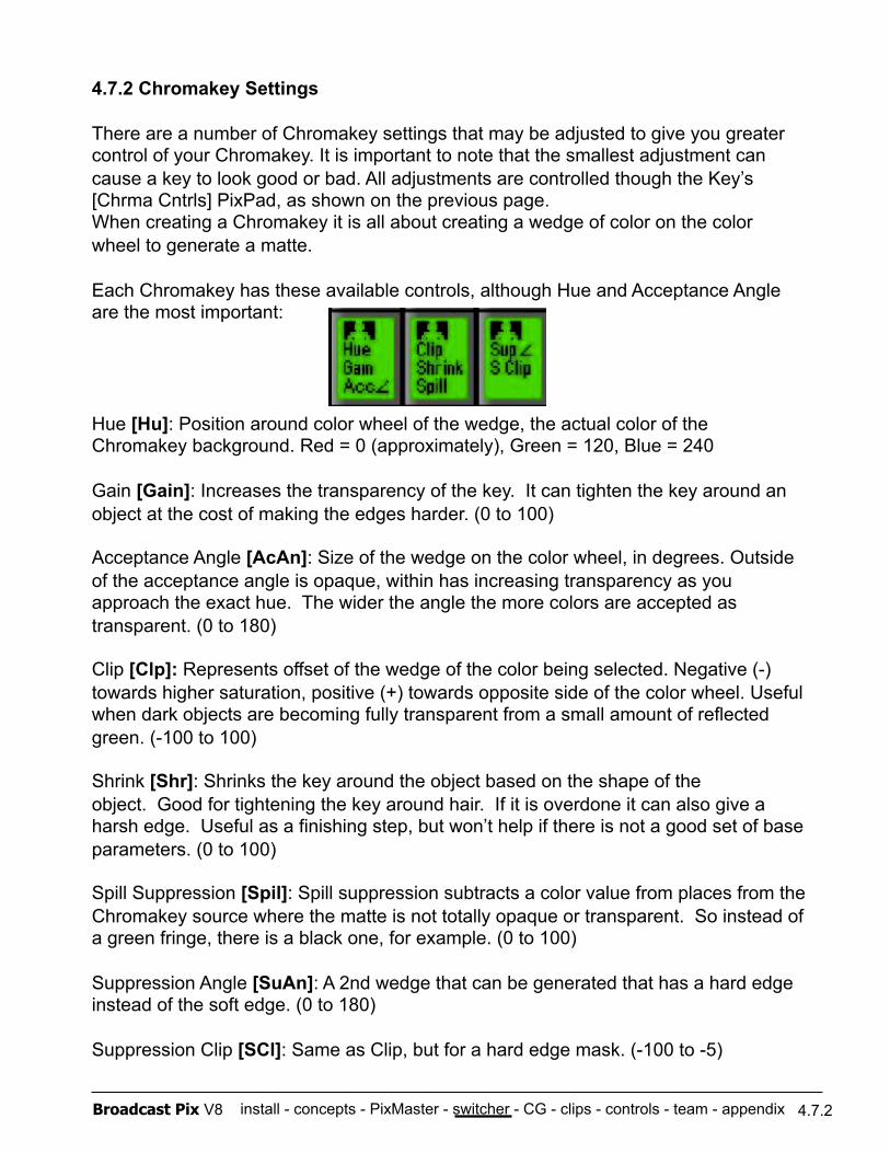
install - concepts - PixMaster - switcher - CG - clips - controls - team - appendix Broadcast Pix V8
4.7.2 Chromakey Settings
There are a number of Chromakey settings that may be adjusted to give you greater control of your Chromakey. It is important to note that the smallest adjustment can cause a key to look good or bad. All adjustments are controlled though the Key’s [Chrma Cntrls] PixPad, as shown on the previous page. When creating a Chromakey it is all about creating a wedge of color on the color wheel to generate a matte.
Each Chromakey has these available controls, although Hue and Acceptance Angle are the most important:
Hue [Hu]: Position around color wheel of the wedge, the actual color of the Chromakey background. Red = 0 (approximately), Green = 120, Blue = 240
Gain [Gain]: Increases the transparency of the key. It can tighten the key around an object at the cost of making the edges harder. (0 to 100)
Acceptance Angle [AcAn]: Size of the wedge on the color wheel, in degrees. Outside of the acceptance angle is opaque, within has increasing transparency as you approach the exact hue. The wider the angle the more colors are accepted as transparent. (0 to 180)
Clip [Clp]: Represents offset of the wedge of the color being selected. Negative (-) towards higher saturation, positive (+) towards opposite side of the color wheel. Useful when dark objects are becoming fully transparent from a small amount of reflected green. (-100 to 100)
Shrink [Shr]: Shrinks the key around the object based on the shape of the object. Good for tightening the key around hair. If it is overdone it can also give a harsh edge. Useful as a finishing step, but won’t help if there is not a good set of base parameters. (0 to 100)
Spill Suppression [Spil]: Spill suppression subtracts a color value from places from the !Chromakey source where the matte is not totally opaque or transparent. So instead of a green fringe, there is a black one, for example. (0 to 100)
Suppression Angle [SuAn]: A 2nd wedge that can be generated that has a hard edge instead of the soft edge. (0 to 180)
Suppression Clip [SCl]: Same as Clip, but for a hard edge mask. (-100 to -5)
4.7.2
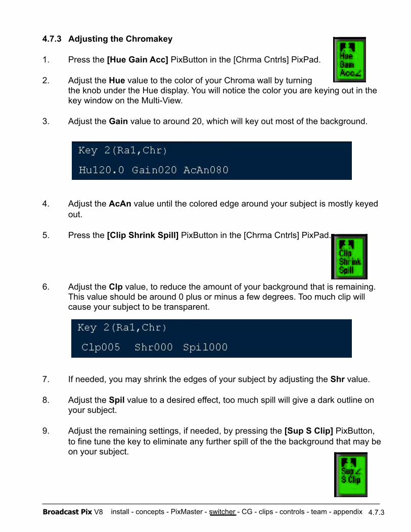
install - concepts - PixMaster - switcher - CG - clips - controls - team - appendix Broadcast Pix V8
4.7.3 Adjusting the Chromakey
1. Press the [Hue Gain Acc] PixButton in the [Chrma Cntrls] PixPad.
2. Adjust the Hue value to the color of your Chroma wall by turning the knob under the Hue display. You will notice the color you are keying out in the key window on the Multi-View.
3. Adjust the Gain value to around 20, which will key out most of the background.
4. Adjust the AcAn value until the colored edge around your subject is mostly keyed out.
5. Press the [Clip Shrink Spill] PixButton in the [Chrma Cntrls] PixPad.
6. Adjust the Clp value, to reduce the amount of your background that is remaining. This value should be around 0 plus or minus a few degrees. Too much clip will cause your subject to be transparent.
7. If needed, you may shrink the edges of your subject by adjusting the Shr value.
8. Adjust the Spil value to a desired effect, too much spill will give a dark outline on your subject.
9. Adjust the remaining settings, if needed, by pressing the [Sup S Clip] PixButton, to fine tune the key to eliminate any further spill of the the background that may be on your subject.
4.7.3
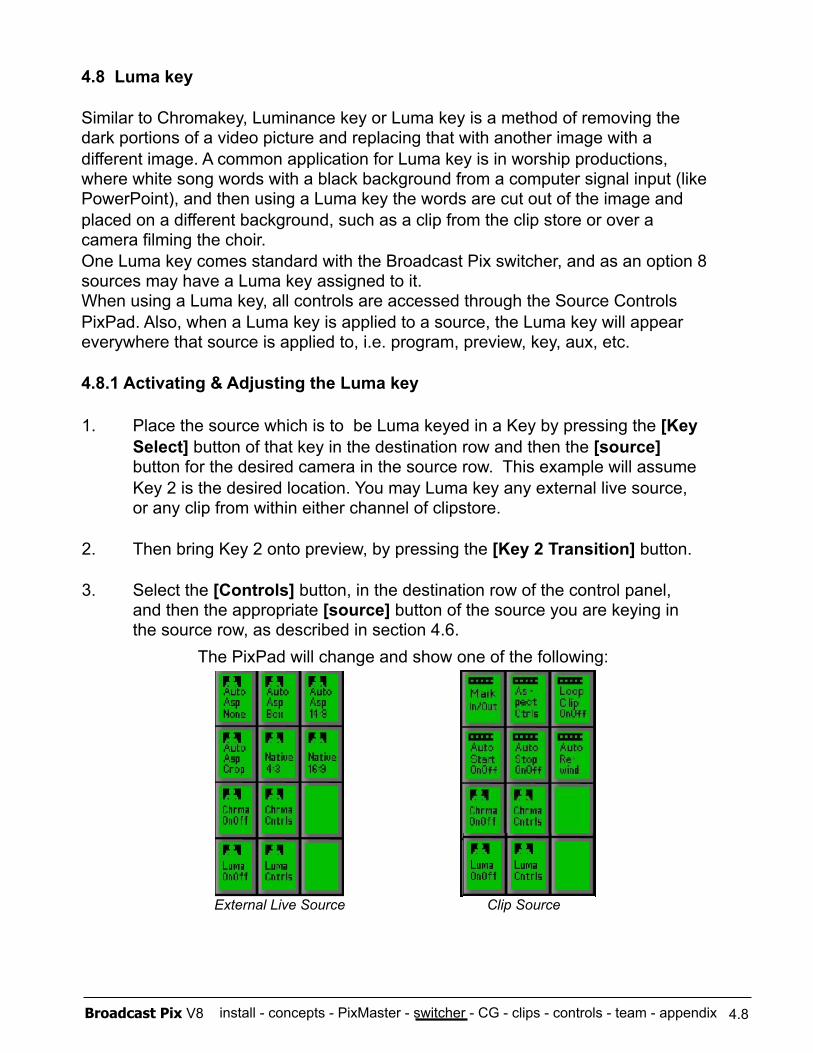
install - concepts - PixMaster - switcher - CG - clips - controls - team - appendix Broadcast Pix V8
4.8 Luma key
Similar to Chromakey, Luminance key or Luma key is a method of removing the dark portions of a video picture and replacing that with another image with a different image. A common application for Luma key is in worship productions, where white song words with a black background from a computer signal input (like PowerPoint), and then using a Luma key the words are cut out of the image and placed on a different background, such as a clip from the clip store or over a camera filming the choir. One Luma key comes standard with the Broadcast Pix switcher, and as an option 8 sources may have a Luma key assigned to it. When using a Luma key, all controls are accessed through the Source Controls PixPad. Also, when a Luma key is applied to a source, the Luma key will appear everywhere that source is applied to, i.e. program, preview, key, aux, etc.
4.8.1 Activating & Adjusting the Luma key
1. Place the source which is to be Luma keyed in a Key by pressing the [Key Select] button of that key in the destination row and then the [source] button for the desired camera in the source row. This example will assume Key 2 is the desired location. You may Luma key any external live source, or any clip from within either channel of clipstore.
2. Then bring Key 2 onto preview, by pressing the [Key 2 Transition] button.
3. Select the [Controls] button, in the destination row of the control panel, and then the appropriate [source] button of the source you are keying in the source row, as described in section 4.6. The PixPad will change and show one of the following:
4.8
External Live Source Clip Source
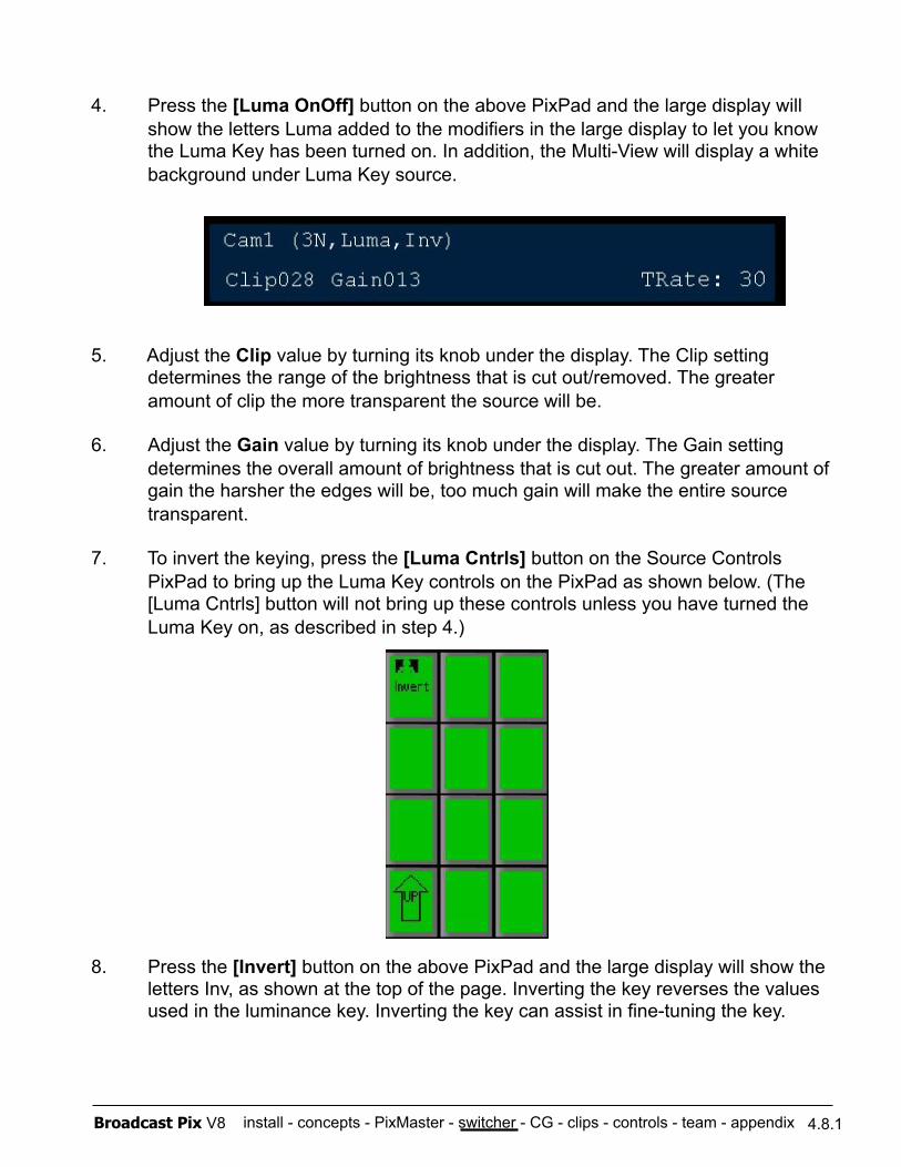
install - concepts - PixMaster - switcher - CG - clips - controls - team - appendix Broadcast Pix V8
4. Press the [Luma OnOff] button on the above PixPad and the large display will show the letters Luma added to the modifiers in the large display to let you know the Luma Key has been turned on. In addition, the Multi-View will display a white background under Luma Key source.
5. Adjust the Clip value by turning its knob under the display. The Clip setting determines the range of the brightness that is cut out/removed. The greater amount of clip the more transparent the source will be.
6. Adjust the Gain value by turning its knob under the display. The Gain setting determines the overall amount of brightness that is cut out. The greater amount of gain the harsher the edges will be, too much gain will make the entire source transparent.
7. To invert the keying, press the [Luma Cntrls] button on the Source Controls PixPad to bring up the Luma Key controls on the PixPad as shown below. (The [Luma Cntrls] button will not bring up these controls unless you have turned the Luma Key on, as described in step 4.)
8. Press the [Invert] button on the above PixPad and the large display will show the letters Inv, as shown at the top of the page. Inverting the key reverses the values used in the luminance key. Inverting the key can assist in fine-tuning the key.
4.8.1
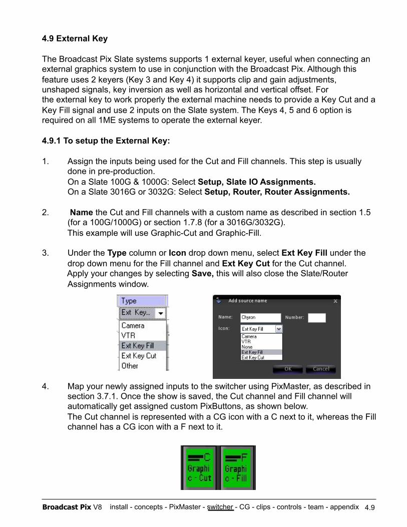
install - concepts - PixMaster - switcher - CG - clips - controls - team - appendix Broadcast Pix V8
4.9 External Key
The Broadcast Pix Slate systems supports 1 external keyer, useful when connecting an external graphics system to use in conjunction with the Broadcast Pix. Although this feature uses 2 keyers (Key 3 and Key 4) it supports clip and gain adjustments, unshaped signals, key inversion as well as horizontal and vertical offset. For the external key to work properly the external machine needs to provide a Key Cut and a Key Fill signal and use 2 inputs on the Slate system. The Keys 4, 5 and 6 option is required on all 1ME systems to operate the external keyer.
4.9.1 To setup the External Key:
1. Assign the inputs being used for the Cut and Fill channels. This step is usually done in pre-production. On a Slate 100G & 1000G: Select Setup, Slate IO Assignments. On a Slate 3016G or 3032G: Select Setup, Router, Router Assignments.
2. Name the Cut and Fill channels with a custom name as described in section 1.5 (for a 100G/1000G) or section 1.7.8 (for a 3016G/3032G). This example will use Graphic-Cut and Graphic-Fill.
3. Under the Type column or Icon drop down menu, select Ext Key Fill under the drop down menu for the Fill channel and Ext Key Cut for the Cut channel. Apply your changes by selecting Save, this will also close the Slate/Router Assignments window.
4. Map your newly assigned inputs to the switcher using PixMaster, as described in section 3.7.1. Once the show is saved, the Cut channel and Fill channel will automatically get assigned custom PixButtons, as shown below. The Cut channel is represented with a CG icon with a C next to it, whereas the Fill channel has a CG icon with a F next to it.
4.9
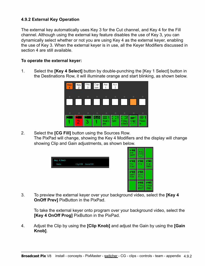
install - concepts - PixMaster - switcher - CG - clips - controls - team - appendix Broadcast Pix V8
4.9.2 External Key Operation
The external key automatically uses Key 3 for the Cut channel, and Key 4 for the Fill channel. Although using the external key feature disables the use of Key 3, you can dynamically select whether or not you are using Key 4 as the external keyer, enabling the use of Key 3. When the external keyer is in use, all the Keyer Modifiers discussed in section 4 are still available.
To operate the external keyer:
1. Select the [Key 4 Select] button by double-punching the [Key 1 Select] button in the Destinations Row, it will illuminate orange and start blinking, as shown below.
2. Select the [CG Fill] button using the Sources Row. The PixPad will change, showing the Key 4 Modifiers and the display will change showing Clip and Gain adjustments, as shown below.
3. To preview the external keyer over your background video, select the [Key 4 OnOff Prev] PixButton in the PixPad.
To take the external keyer onto program over your background video, select the [Key 4 OnOff Prog] PixButton in the PixPad.
4. Adjust the Clip by using the [Clip Knob] and adjust the Gain by using the [Gain Knob].
4.9.2
Key 4
Key 2
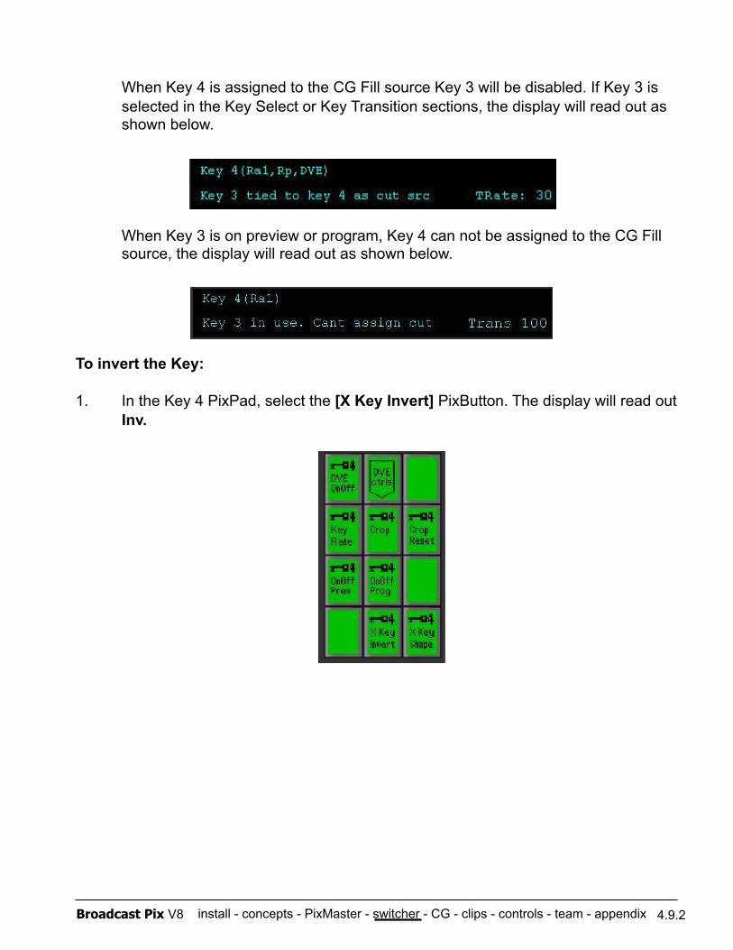
install - concepts - PixMaster - switcher - CG - clips - controls - team - appendix Broadcast Pix V8
When Key 4 is assigned to the CG Fill source Key 3 will be disabled. If Key 3 is selected in the Key Select or Key Transition sections, the display will read out as shown below.
When Key 3 is on preview or program, Key 4 can not be assigned to the CG Fill source, the display will read out as shown below.
To invert the Key:
1. In the Key 4 PixPad, select the [X Key Invert] PixButton. The display will read out Inv.
4.9.2
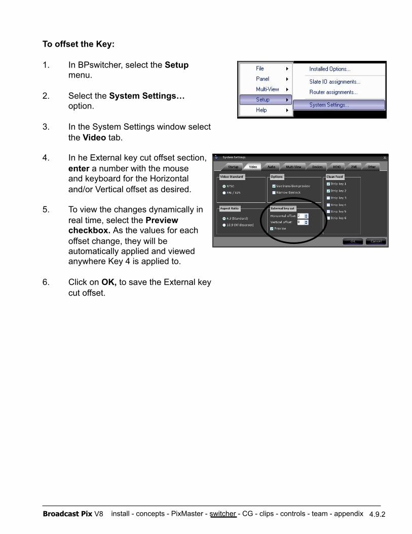
install - concepts - PixMaster - switcher - CG - clips - controls - team - appendix Broadcast Pix V8
To offset the Key:
1. In BPswitcher, select the Setup menu.
2. Select the System Settings… option.
3. In the System Settings window select the Video tab.
4. In he External key cut offset section, enter a number with the mouse and keyboard for the Horizontal and/or Vertical offset as desired.
5. To view the changes dynamically in real time, select the Preview checkbox. As the values for each offset change, they will be automatically applied and viewed anywhere Key 4 is applied to.
6. Click on OK, to save the External key cut offset.
4.9.2
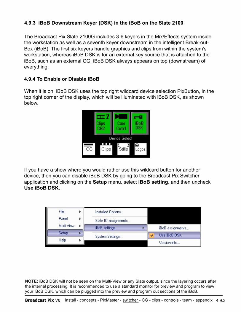
install - concepts - PixMaster - switcher - CG - clips - controls - team - appendix Broadcast Pix V8
4.9.3 iBoB Downstream Keyer (DSK) in the iBoB on the Slate 2100
4.9.3
The Broadcast Pix Slate 2100G includes 3-6 keyers in the Mix/Effects system inside the workstation as well as a seventh keyer downstream in the intelligent Break-out-Box (iBoB). The first six keyers handle graphics and clips from within the system’s workstation, whereas iBoB DSK is for an external key source that is attached to the iBoB, such as an external CG. iBoB DSK always appears on top (downstream) of everything.
4.9.4 To Enable or Disable iBoB
When it is on, iBoB DSK uses the top right wildcard device selection PixButton, in the top right corner of the display, which will be illuminated with iBoB DSK, as shown below.
If you have a show where you would rather use this wildcard button for another device, then you can disable iBoB DSK by going to the Broadcast Pix Switcher application and clicking on the Setup menu, select iBoB setting, and then uncheck Use iBoB DSK.
NOTE: iBoB DSK will not be seen on the Multi-View or any Slate output, since the layering occurs after the internal processing. It is recommended to use a standard monitor for preview and program to view your iBoB DSK, which can be plugged into the preview and program out sections of the iBoB.
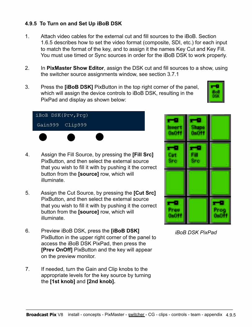
install - concepts - PixMaster - switcher - CG - clips - controls - team - appendix Broadcast Pix V8 4.9.5
4.9.5 To Turn on and Set Up iBoB DSK
1. Attach video cables for the external cut and fill sources to the iBoB. Section 1.6.5 describes how to set the video format (composite, SDI, etc.) for each input to match the format of the key, and to assign it the names Key Cut and Key Fill. You must use timed or Sync sources in order for the iBoB DSK to work properly.
2. In PixMaster Show Editor, assign the DSK cut and fill sources to a show, using the switcher source assignments window, see section 3.7.1
3. Press the [iBoB DSK] PixButton in the top right corner of the panel, which will assign the device controls to iBoB DSK, resulting in the PixPad and display as shown below:
4. Assign the Fill Source, by pressing the [Fill Src] PixButton, and then select the external source that you wish to fill it with by pushing it the correct button from the [source] row, which will illuminate.
5. Assign the Cut Source, by pressing the [Cut Src] PixButton, and then select the external source that you wish to fill it with by pushing it the correct button from the [source] row, which will illuminate.
6. Preview iBoB DSK, press the [iBoB DSK] PixButton in the upper right corner of the panel to access the iBoB DSK PixPad, then press the [Prev OnOff] PixButton and the key will appear on the preview monitor.
7. If needed, turn the Gain and Clip knobs to the appropriate levels for the key source by turning the [1st knob] and [2nd knob].
iBoB DSK PixPad
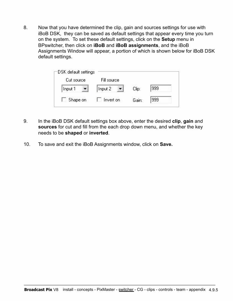
install - concepts - PixMaster - switcher - CG - clips - controls - team - appendix Broadcast Pix V8 4.9.5
8. Now that you have determined the clip, gain and sources settings for use with iBoB DSK, they can be saved as default settings that appear every time you turn on the system. To set these default settings, click on the Setup menu in BPswitcher, then click on iBoB and iBoB assignments, and the iBoB Assignments Window will appear, a portion of which is shown below for iBoB DSK default settings.
9. In the iBoB DSK default settings box above, enter the desired clip, gain and sources for cut and fill from the each drop down menu, and whether the key needs to be shaped or inverted.
10. To save and exit the iBoB Assignments window, click on Save.

install - concepts - PixMaster - switcher - CG - clips - controls - team - appendix Broadcast Pix V8 4.9.6
4.9.6 To Operate iBoB DSK
1. To activate the device controls for iBoB DSK control, press the [iBoB DSK] wildcard PixButton in the upper right corner of the panel.
2. To preview the DSK, press the [Prev OnOff] PixButton and the key will appear on your external preview monitor.
3. To bring the DSK on air, press the [Prog OnOff] PixButton and the key will appear on your external program output.
iBoB DSK can be taken off preview or program by pressing the [Prev OnOff] and [Prog OnOff] buttons again, respectively.
iBoB DSK PixPad
The key controls may be changed from this PixPad at any time during a show, even if default values have been set for them, including Invert OnOff, Shape OnOff, Cut Src, Fill Src on the above PixPad, and the knobs for Clip and Gain.
As each modifier is applied or changed its status is reflected in the display, as shown below.
Modifying iBoB DSK
NOTE: iBoB DSK can only cut on/off, you can not add any mix/effects or tie it to a transition. iBoB DSK also is downstream of all the keys, meaning that it will appear on top of all key layers.
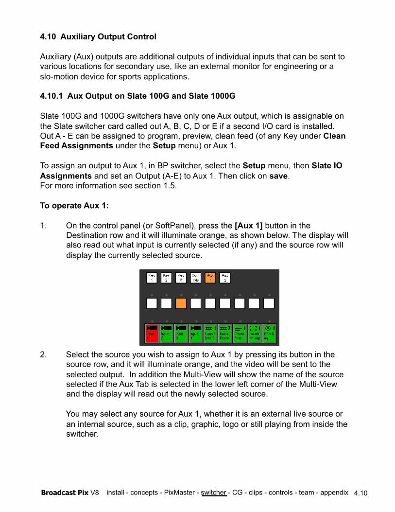
install - concepts - PixMaster - switcher - CG - clips - controls - team - appendix Broadcast Pix V8
4.10 Auxiliary Output Control
Auxiliary (Aux) outputs are additional outputs of individual inputs that can be sent to various locations for secondary use, like an external monitor for engineering or a slo-motion device for sports applications.
4.10.1 Aux Output on Slate 100G and Slate 1000G
Slate 100G and 1000G switchers have only one Aux output, which is assignable on the Slate switcher card called out A, B, C, D or E if a second I/O card is installed. Out A - E can be assigned to program, preview, clean feed (of any Key under Clean Feed Assignments under the Setup menu) or Aux 1.
To assign an output to Aux 1, in BP switcher, select the Setup menu, then Slate IO Assignments and set an Output (A-E) to Aux 1. Then click on save. For more information see section 1.5.
To operate Aux 1:
1. On the control panel (or SoftPanel), press the [Aux 1] button in the Destination row and it will illuminate orange, as shown below. The display will also read out what input is currently selected (if any) and the source row will display the currently selected source.
2. Select the source you wish to assign to Aux 1 by pressing its button in the source row, and it will illuminate orange, and the video will be sent to the selected output. In addition the Multi-View will show the name of the source selected if the Aux Tab is selected in the lower left corner of the Multi-View and the display will read out the newly selected source.
You may select any source for Aux 1, whether it is an external live source or an internal source, such as a clip, graphic, logo or still playing from inside the switcher.
4.10
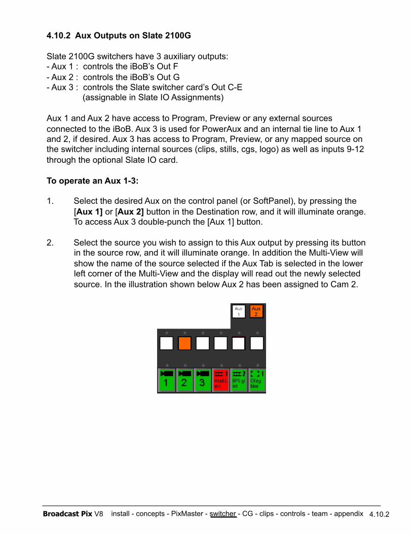
install - concepts - PixMaster - switcher - CG - clips - controls - team - appendix Broadcast Pix V8
4.10.2 Aux Outputs on Slate 2100G
Slate 2100G switchers have 3 auxiliary outputs: - Aux 1 : controls the iBoB’s Out F - Aux 2 : controls the iBoB’s Out G - Aux 3 : controls the Slate switcher card’s Out C-E (assignable in Slate IO Assignments)
Aux 1 and Aux 2 have access to Program, Preview or any external sources connected to the iBoB. Aux 3 is used for PowerAux and an internal tie line to Aux 1 and 2, if desired. Aux 3 has access to Program, Preview, or any mapped source on the switcher including internal sources (clips, stills, cgs, logo) as well as inputs 9-12 through the optional Slate IO card.
To operate an Aux 1-3:
1. Select the desired Aux on the control panel (or SoftPanel), by pressing the [Aux 1] or [Aux 2] button in the Destination row, and it will illuminate orange.
To access Aux 3 double-punch the [Aux 1] button.
2. Select the source you wish to assign to this Aux output by pressing its button in the source row, and it will illuminate orange. In addition the Multi-View will show the name of the source selected if the Aux Tab is selected in the lower left corner of the Multi-View and the display will read out the newly selected source. In the illustration shown below Aux 2 has been assigned to Cam 2.
Aux 2
4.10.2
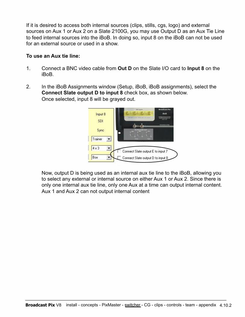
install - concepts - PixMaster - switcher - CG - clips - controls - team - appendix Broadcast Pix V8
If it is desired to access both internal sources (clips, stills, cgs, logo) and external sources on Aux 1 or Aux 2 on a Slate 2100G, you may use Output D as an Aux Tie Line to feed internal sources into the iBoB. In doing so, input 8 on the iBoB can not be used for an external source or used in a show.
To use an Aux tie line:
1. Connect a BNC video cable from Out D on the Slate I/O card to Input 8 on the iBoB.
2. In the iBoB Assignments window (Setup, iBoB, iBoB assignments), select the Connect Slate output D to input 8 check box, as shown below. Once selected, input 8 will be grayed out.
Now, output D is being used as an internal aux tie line to the iBoB, allowing you to select any external or internal source on either Aux 1 or Aux 2. Since there is only one internal aux tie line, only one Aux at a time can output internal content. Aux 1 and Aux 2 can not output internal content
4.10.2

install - concepts - PixMaster - switcher - CG - clips - controls - team - appendix Broadcast Pix V8
4.10.3 Aux Outputs on Slate 3016G
Slate 3016G switchers have a total of 6 auxiliary outputs, which connect to the 16x16 Router through Outputs 3-8. The outputs can either be assigned in pre-production in the Router Assignments window, see section 1.7.8, or through the Destinations Row of the Control Panel. The Control Panel can control Auxes 1-4, leaving 2 outputs to be assigned through Router Assignments or a Remote Aux Panel.
There is 1 Aux Tie Line that connects internal Slate sources such as graphics and clips, to the router to be used in aux bus selection. Only one Aux output at a time may output an internal source. Any external source connected to the router can output to any Aux output at any time.
To operate Aux 1-4:
1. On the Control Panel, press the [Aux 1] or [Aux 2] button, to control Aux 3 double-punch [Aux 1] and to control Aux 4 double-punch [Aux 4], in the Destinations Row and it will illuminate orange, as shown below. Aux 3 and 4 will blink orange.
2. Select the source you wish to assign to Aux 1-4 by pressing its [Source] button in the Sources Row, and it will illuminate orange, and the video will be sent to the selected output. In addition the Multi-View will show the name of the source selected if the Aux Tab is selected in the lower left corner of the Multi-View and the display will read out the newly selected source. In the illustration shown below Aux 2 has been assigned to Cam 2.
4.10.3
NOTE: Since Aux bus selection is a vertical interval cut, there may be a glitch on the Aux output if switching between different formats (SD to HD) and if switching between genlocked and non-genlocked sources.
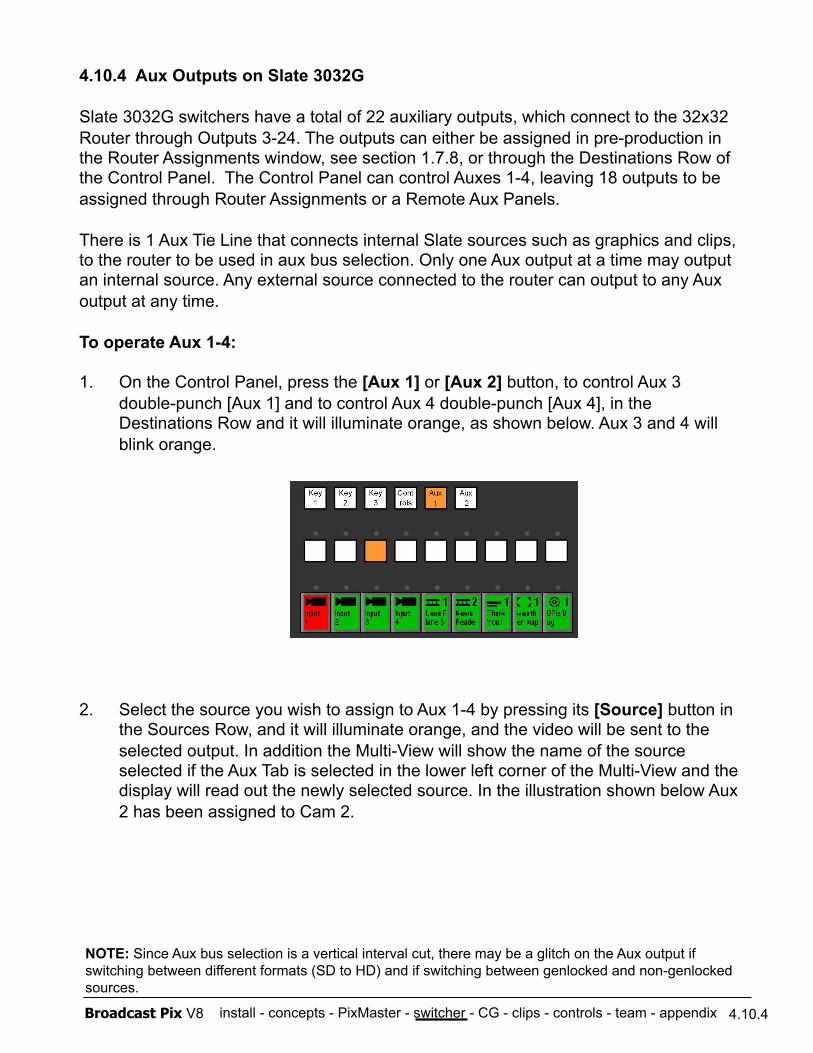
install - concepts - PixMaster - switcher - CG - clips - controls - team - appendix Broadcast Pix V8
4.10.4 Aux Outputs on Slate 3032G
Slate 3032G switchers have a total of 22 auxiliary outputs, which connect to the 32x32 Router through Outputs 3-24. The outputs can either be assigned in pre-production in the Router Assignments window, see section 1.7.8, or through the Destinations Row of the Control Panel. The Control Panel can control Auxes 1-4, leaving 18 outputs to be assigned through Router Assignments or a Remote Aux Panels.
There is 1 Aux Tie Line that connects internal Slate sources such as graphics and clips, to the router to be used in aux bus selection. Only one Aux output at a time may output an internal source. Any external source connected to the router can output to any Aux output at any time.
To operate Aux 1-4:
1. On the Control Panel, press the [Aux 1] or [Aux 2] button, to control Aux 3 double-punch [Aux 1] and to control Aux 4 double-punch [Aux 4], in the Destinations Row and it will illuminate orange, as shown below. Aux 3 and 4 will blink orange.
2. Select the source you wish to assign to Aux 1-4 by pressing its [Source] button in the Sources Row, and it will illuminate orange, and the video will be sent to the selected output. In addition the Multi-View will show the name of the source selected if the Aux Tab is selected in the lower left corner of the Multi-View and the display will read out the newly selected source. In the illustration shown below Aux 2 has been assigned to Cam 2.
4.10.4
NOTE: Since Aux bus selection is a vertical interval cut, there may be a glitch on the Aux output if switching between different formats (SD to HD) and if switching between genlocked and non-genlocked sources.
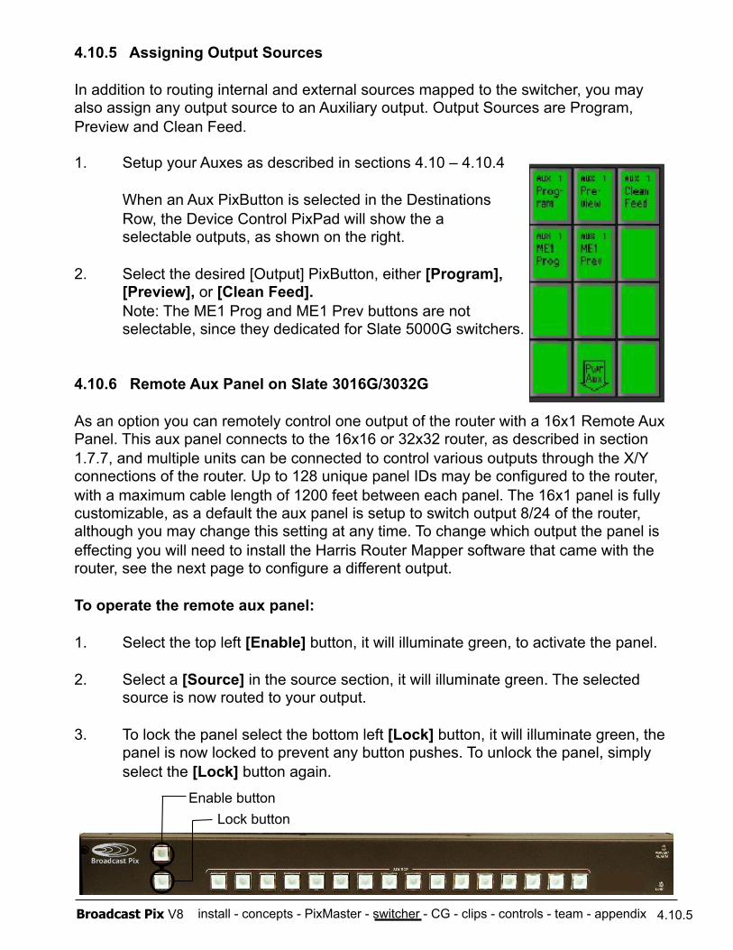
install - concepts - PixMaster - switcher - CG - clips - controls - team - appendix Broadcast Pix V8
4.10.5 Assigning Output Sources
In addition to routing internal and external sources mapped to the switcher, you may also assign any output source to an Auxiliary output. Output Sources are Program, Preview and Clean Feed.
1. Setup your Auxes as described in sections 4.10 – 4.10.4
When an Aux PixButton is selected in the Destinations Row, the Device Control PixPad will show the a selectable outputs, as shown on the right.
2. Select the desired [Output] PixButton, either [Program], [Preview], or [Clean Feed]. Note: The ME1 Prog and ME1 Prev buttons are not selectable, since they dedicated for Slate 5000G switchers.
4.10.6 Remote Aux Panel on Slate 3016G/3032G
As an option you can remotely control one output of the router with a 16x1 Remote Aux Panel. This aux panel connects to the 16x16 or 32x32 router, as described in section 1.7.7, and multiple units can be connected to control various outputs through the X/Y connections of the router. Up to 128 unique panel IDs may be configured to the router, with a maximum cable length of 1200 feet between each panel. The 16x1 panel is fully customizable, as a default the aux panel is setup to switch output 8/24 of the router, although you may change this setting at any time. To change which output the panel is effecting you will need to install the Harris Router Mapper software that came with the router, see the next page to configure a different output.
To operate the remote aux panel:
1. Select the top left [Enable] button, it will illuminate green, to activate the panel.
2. Select a [Source] in the source section, it will illuminate green. The selected source is now routed to your output.
3. To lock the panel select the bottom left [Lock] button, it will illuminate green, the panel is now locked to prevent any button pushes. To unlock the panel, simply
select the [Lock] button again.
4.10.5
Enable button Lock button
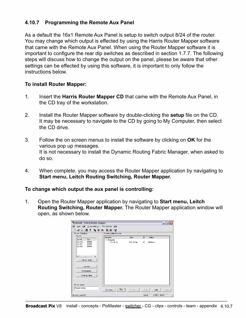
install - concepts - PixMaster - switcher - CG - clips - controls - team - appendix Broadcast Pix V8
4.10.7 Programming the Remote Aux Panel
As a default the 16x1 Remote Aux Panel is setup to switch output 8/24 of the router. You may change which output is effected by using the Harris Router Mapper software that came with the Remote Aux Panel. When using the Router Mapper software it is important to configure the rear dip switches as described in section 1.7.7. The following steps will discuss how to change the output on the panel, please be aware that other settings can be effected by using this software, it is important to only follow the instructions below.
To install Router Mapper:
1. Insert the Harris Router Mapper CD that came with the Remote Aux Panel, in the CD tray of the workstation.
2. Install the Router Mapper software by double-clicking the setup file on the CD. It may be necessary to navigate to the CD by going to My Computer, then select
the CD drive.
3. Follow the on screen menus to install the software by clicking on OK for the various pop up messages. It is not necessary to install the Dynamic Routing Fabric Manager, when asked to do so.
4. When complete, you may access the Router Mapper application by navigating to Start menu, Leitch Routing Switching, Router Mapper.
To change which output the aux panel is controlling:
1. Open the Router Mapper application by navigating to Start menu, Leitch Routing Switching, Router Mapper. The Router Mapper application window will open, as shown below.
4.10.7
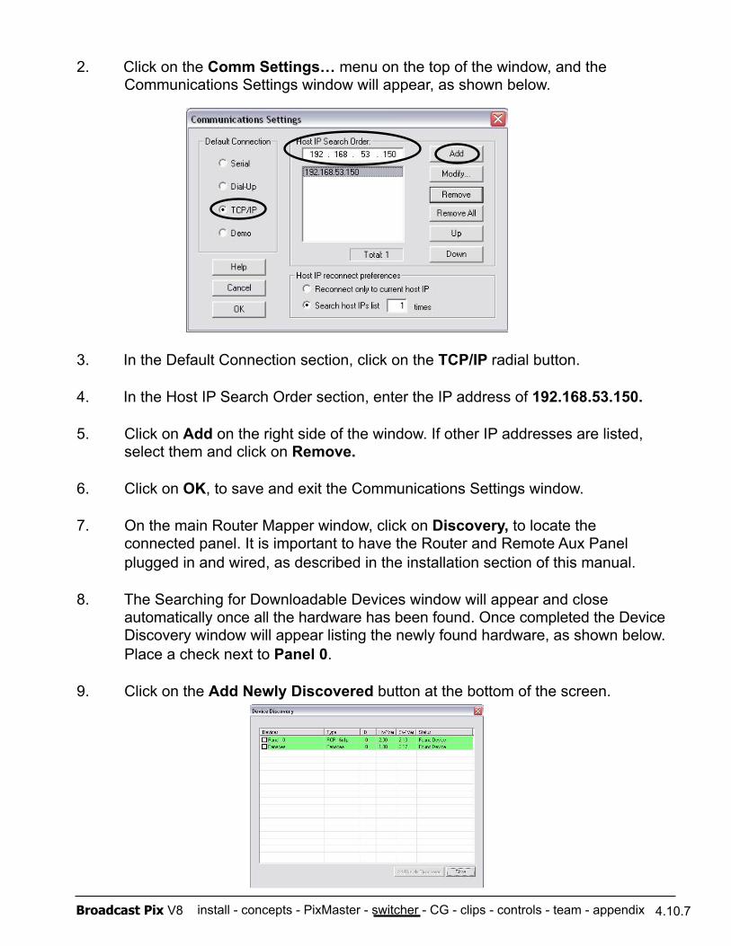
install - concepts - PixMaster - switcher - CG - clips - controls - team - appendix Broadcast Pix V8 4.10.7
2. Click on the Comm Settings… menu on the top of the window, and the Communications Settings window will appear, as shown below.
3. In the Default Connection section, click on the TCP/IP radial button.
4. In the Host IP Search Order section, enter the IP address of 192.168.53.150.
5. Click on Add on the right side of the window. If other IP addresses are listed, select them and click on Remove.
6. Click on OK, to save and exit the Communications Settings window.
7. On the main Router Mapper window, click on Discovery, to locate the connected panel. It is important to have the Router and Remote Aux Panel plugged in and wired, as described in the installation section of this manual.
8. The Searching for Downloadable Devices window will appear and close automatically once all the hardware has been found. Once completed the Device Discovery window will appear listing the newly found hardware, as shown below. Place a check next to Panel 0.
9. Click on the Add Newly Discovered button at the bottom of the screen.
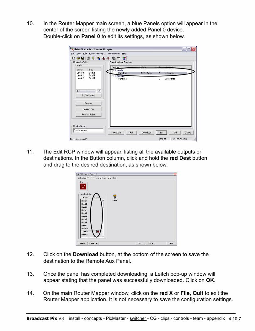
install - concepts - PixMaster - switcher - CG - clips - controls - team - appendix Broadcast Pix V8
10. In the Router Mapper main screen, a blue Panels option will appear in the center of the screen listing the newly added Panel 0 device. Double-click on Panel 0 to edit its settings, as shown below.
11. The Edit RCP window will appear, listing all the available outputs or destinations. In the Button column, click and hold the red Dest button and drag to the desired destination, as shown below.
12. Click on the Download button, at the bottom of the screen to save the destination to the Remote Aux Panel.
13. Once the panel has completed downloading, a Leitch pop-up window will appear stating that the panel was successfully downloaded. Click on OK.
14. On the main Router Mapper window, click on the red X or File, Quit to exit the Router Mapper application. It is not necessary to save the configuration settings.
4.10.7
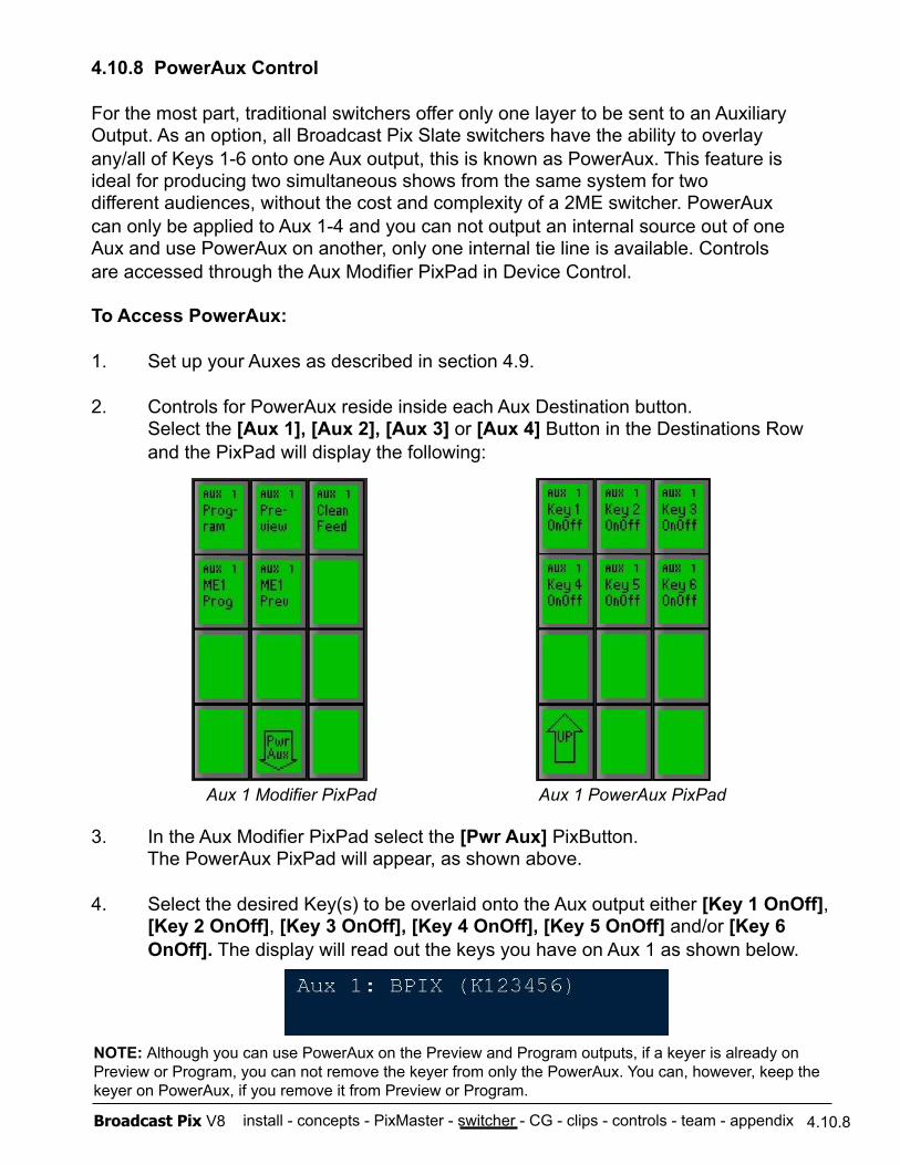
install - concepts - PixMaster - switcher - CG - clips - controls - team - appendix Broadcast Pix V8
4.10.8 PowerAux Control
For the most part, traditional switchers offer only one layer to be sent to an Auxiliary Output. As an option, all Broadcast Pix Slate switchers have the ability to overlay any/all of Keys 1-6 onto one Aux output, this is known as PowerAux. This feature is ideal for producing two simultaneous shows from the same system for two different audiences, without the cost and complexity of a 2ME switcher. PowerAux can only be applied to Aux 1-4 and you can not output an internal source out of one Aux and use PowerAux on another, only one internal tie line is available. Controls are accessed through the Aux Modifier PixPad in Device Control.
To Access PowerAux:
1. Set up your Auxes as described in section 4.9.
2. Controls for PowerAux reside inside each Aux Destination button. Select the [Aux 1], [Aux 2], [Aux 3] or [Aux 4] Button in the Destinations Row and the PixPad will display the following:
3. In the Aux Modifier PixPad select the [Pwr Aux] PixButton. The PowerAux PixPad will appear, as shown above.
4. Select the desired Key(s) to be overlaid onto the Aux output either [Key 1 OnOff], [Key 2 OnOff], [Key 3 OnOff], [Key 4 OnOff], [Key 5 OnOff] and/or [Key 6 OnOff]. The display will read out the keys you have on Aux 1 as shown below.
4.10.8
NOTE: Although you can use PowerAux on the Preview and Program outputs, if a keyer is already on Preview or Program, you can not remove the keyer from only the PowerAux. You can, however, keep the keyer on PowerAux, if you remove it from Preview or Program.
Aux 1 Modifier PixPad Aux 1 PowerAux PixPad
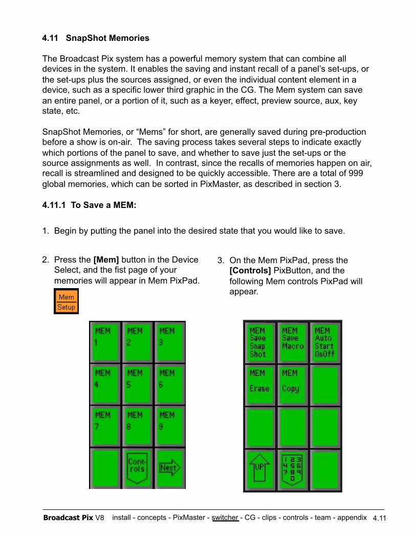
install - concepts - PixMaster - switcher - CG - clips - controls - team - appendix Broadcast Pix V8
4.11 SnapShot Memories
4.11
The Broadcast Pix system has a powerful memory system that can combine all devices in the system. It enables the saving and instant recall of a panel’s set-ups, or the set-ups plus the sources assigned, or even the individual content element in a device, such as a specific lower third graphic in the CG. The Mem system can save an entire panel, or a portion of it, such as a keyer, effect, preview source, aux, key state, etc.
SnapShot Memories, or “Mems” for short, are generally saved during pre-production before a show is on-air. The saving process takes several steps to indicate exactly which portions of the panel to save, and whether to save just the set-ups or the source assignments as well. In contrast, since the recalls of memories happen on air, recall is streamlined and designed to be quickly accessible. There are a total of 999 global memories, which can be sorted in PixMaster, as described in section 3.
4.11.1 To Save a MEM:
2. Press the [Mem] button in the Device Select, and the fist page of your memories will appear in Mem PixPad.
3. On the Mem PixPad, press the [Controls] PixButton, and the following Mem controls PixPad will appear.
1. Begin by putting the panel into the desired state that you would like to save.
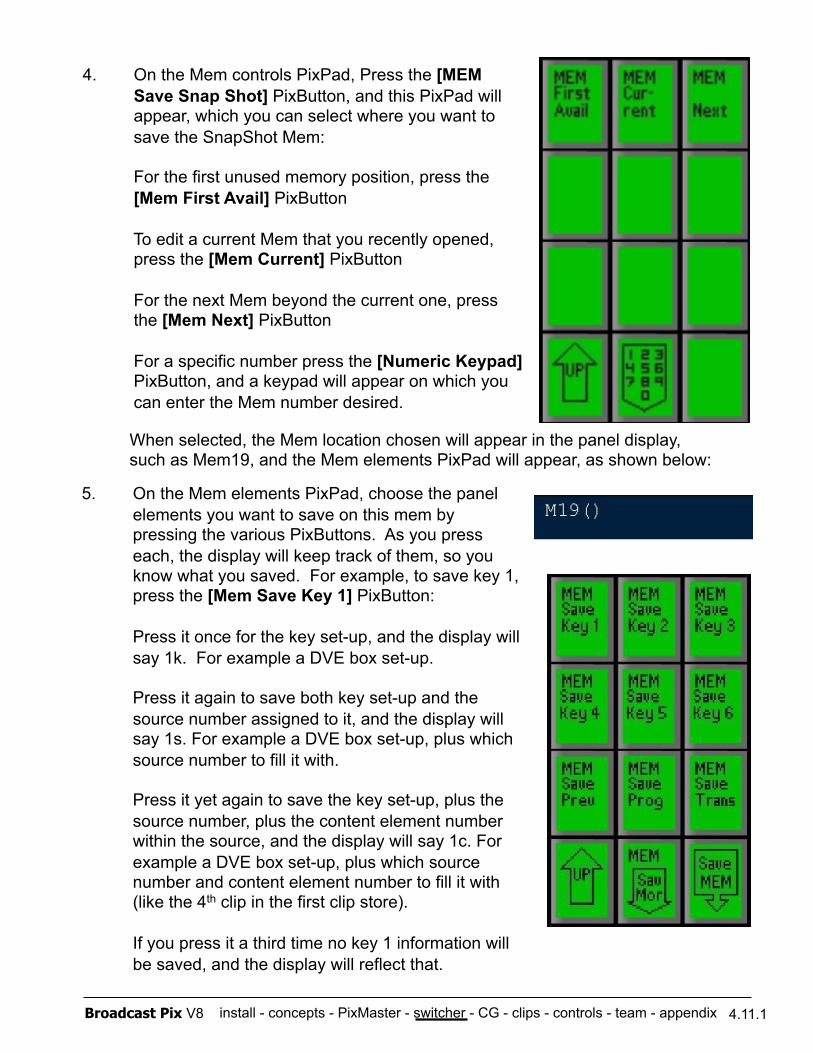
install - concepts - PixMaster - switcher - CG - clips - controls - team - appendix Broadcast Pix V8 4.11.1
4. On the Mem controls PixPad, Press the [MEM Save Snap Shot] PixButton, and this PixPad will appear, which you can select where you want to save the SnapShot Mem:
For the first unused memory position, press the [Mem First Avail] PixButton
To edit a current Mem that you recently opened, press the [Mem Current] PixButton
For the next Mem beyond the current one, press the [Mem Next] PixButton
For a specific number press the [Numeric Keypad] PixButton, and a keypad will appear on which you can enter the Mem number desired.
5. On the Mem elements PixPad, choose the panel elements you want to save on this mem by pressing the various PixButtons. As you press each, the display will keep track of them, so you know what you saved. For example, to save key 1, press the [Mem Save Key 1] PixButton:
Press it once for the key set-up, and the display will say 1k. For example a DVE box set-up.
Press it again to save both key set-up and the source number assigned to it, and the display will say 1s. For example a DVE box set-up, plus which source number to fill it with.
Press it yet again to save the key set-up, plus the source number, plus the content element number within the source, and the display will say 1c. For example a DVE box set-up, plus which source number and content element number to fill it with (like the 4th clip in the first clip store).
If you press it a third time no key 1 information will be saved, and the display will reflect that.
When selected, the Mem location chosen will appear in the panel display, such as Mem19, and the Mem elements PixPad will appear, as shown below:
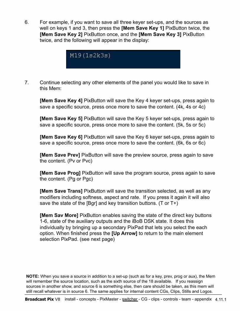
install - concepts - PixMaster - switcher - CG - clips - controls - team - appendix Broadcast Pix V8
6. For example, if you want to save all three keyer set-ups, and the sources as well on keys 1 and 3, then press the [Mem Save Key 1] PixButton twice, the [Mem Save Key 2] PixButton once, and the [Mem Save Key 3] PixButton twice, and the following will appear in the display:
7. Continue selecting any other elements of the panel you would like to save in this Mem:
[Mem Save Key 4] PixButton will save the Key 4 keyer set-ups, press again to save a specific source, press once more to save the content. (4k, 4s or 4c)
[Mem Save Key 5] PixButton will save the Key 5 keyer set-ups, press again to save a specific source, press once more to save the content. (5k, 5s or 5c)
[Mem Save Key 6] PixButton will save the Key 6 keyer set-ups, press again to save a specific source, press once more to save the content. (6k, 6s or 6c)
[Mem Save Prev] PixButton will save the preview source, press again to save the content. (Pv or Pvc)
[Mem Save Prog] PixButton will save the program source, press again to save the content. (Pg or Pgc)
[Mem Save Trans] PixButton will save the transition selected, as well as any modifiers including softness, aspect and rate. If you press it again it will also save the state of the [Bgr] and key transition buttons. (T or T+)
[Mem Sav More] PixButton enables saving the state of the direct key buttons 1-6, state of the auxiliary outputs and the iBoB DSK state. It does this individually by bringing up a secondary PixPad that lets you select the each option. When finished press the [Up Arrow] to return to the main element selection PixPad. (see next page)
4.11.1
NOTE: When you save a source in addition to a set-up (such as for a key, prev, prog or aux), the Mem will remember the source location, such as the sixth source of the 18 available. If you reassign sources in another show, and source 6 is something else, then care should be taken, as this mem will still recall whatever is in source 6. The same applies for internal content CGs, Clips, Stills and Logos.
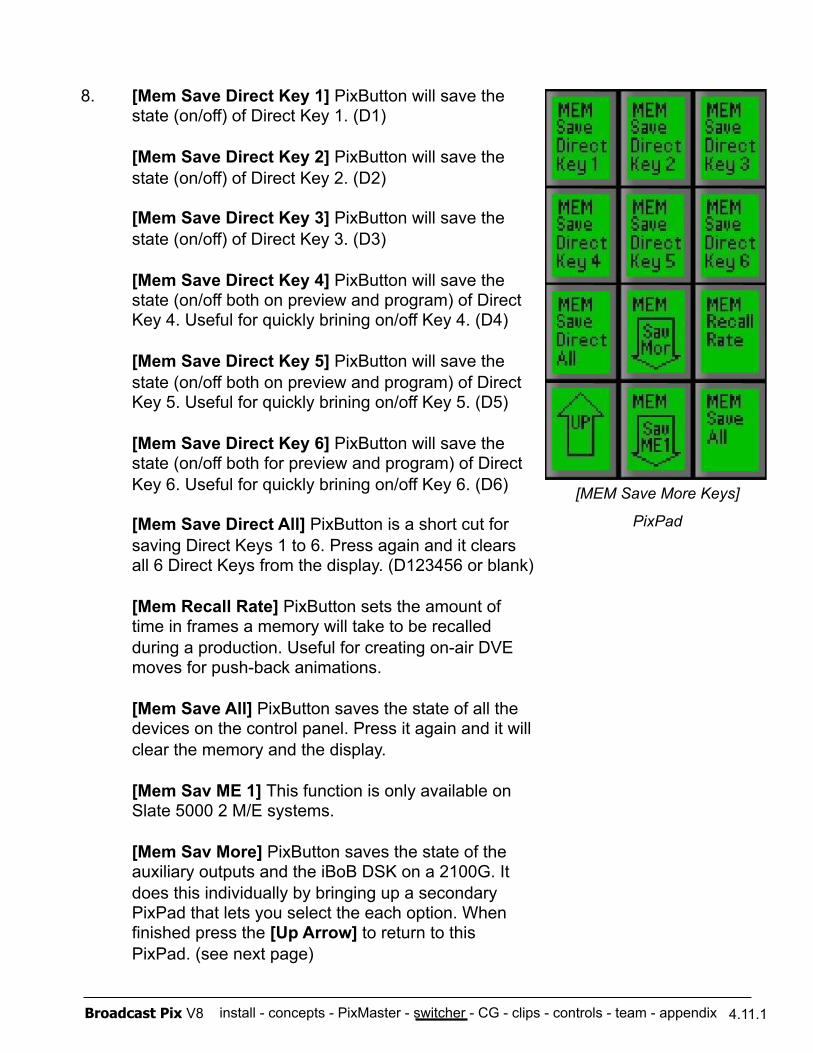
install - concepts - PixMaster - switcher - CG - clips - controls - team - appendix Broadcast Pix V8 4.11.1
8. [Mem Save Direct Key 1] PixButton will save the state (on/off) of Direct Key 1. (D1)
[Mem Save Direct Key 2] PixButton will save the state (on/off) of Direct Key 2. (D2)
[Mem Save Direct Key 3] PixButton will save the state (on/off) of Direct Key 3. (D3)
[Mem Save Direct Key 4] PixButton will save the state (on/off both on preview and program) of Direct Key 4. Useful for quickly brining on/off Key 4. (D4)
[Mem Save Direct Key 5] PixButton will save the state (on/off both on preview and program) of Direct Key 5. Useful for quickly brining on/off Key 5. (D5)
[Mem Save Direct Key 6] PixButton will save the state (on/off both for preview and program) of Direct Key 6. Useful for quickly brining on/off Key 6. (D6)
[Mem Save Direct All] PixButton is a short cut for saving Direct Keys 1 to 6. Press again and it clears all 6 Direct Keys from the display. (D123456 or blank)
[Mem Recall Rate] PixButton sets the amount of time in frames a memory will take to be recalled during a production. Useful for creating on-air DVE moves for push-back animations.
[Mem Save All] PixButton saves the state of all the devices on the control panel. Press it again and it will clear the memory and the display.
[Mem Sav ME 1] This function is only available on Slate 5000 2 M/E systems.
[Mem Sav More] PixButton saves the state of the auxiliary outputs and the iBoB DSK on a 2100G. It does this individually by bringing up a secondary PixPad that lets you select the each option. When finished press the [Up Arrow] to return to this PixPad. (see next page)
[MEM Save More Keys]
PixPad
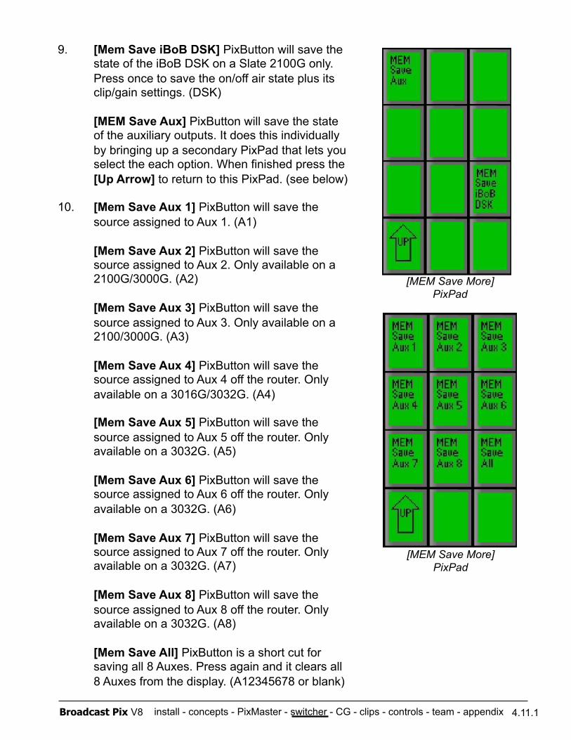
install - concepts - PixMaster - switcher - CG - clips - controls - team - appendix Broadcast Pix V8 4.11.1
9. [Mem Save iBoB DSK] PixButton will save the state of the iBoB DSK on a Slate 2100G only. Press once to save the on/off air state plus its clip/gain settings. (DSK)
[MEM Save Aux] PixButton will save the state of the auxiliary outputs. It does this individually by bringing up a secondary PixPad that lets you select the each option. When finished press the [Up Arrow] to return to this PixPad. (see below)
10. [Mem Save Aux 1] PixButton will save the source assigned to Aux 1. (A1)
[Mem Save Aux 2] PixButton will save the source assigned to Aux 2. Only available on a 2100G/3000G. (A2)
[Mem Save Aux 3] PixButton will save the source assigned to Aux 3. Only available on a 2100/3000G. (A3)
[Mem Save Aux 4] PixButton will save the source assigned to Aux 4 off the router. Only available on a 3016G/3032G. (A4)
[Mem Save Aux 5] PixButton will save the source assigned to Aux 5 off the router. Only available on a 3032G. (A5)
[Mem Save Aux 6] PixButton will save the source assigned to Aux 6 off the router. Only available on a 3032G. (A6)
[Mem Save Aux 7] PixButton will save the source assigned to Aux 7 off the router. Only available on a 3032G. (A7)
[Mem Save Aux 8] PixButton will save the source assigned to Aux 8 off the router. Only available on a 3032G. (A8)
[Mem Save All] PixButton is a short cut for saving all 8 Auxes. Press again and it clears all 8 Auxes from the display. (A12345678 or blank)
[MEM Save More] PixPad
[MEM Save More] PixPad
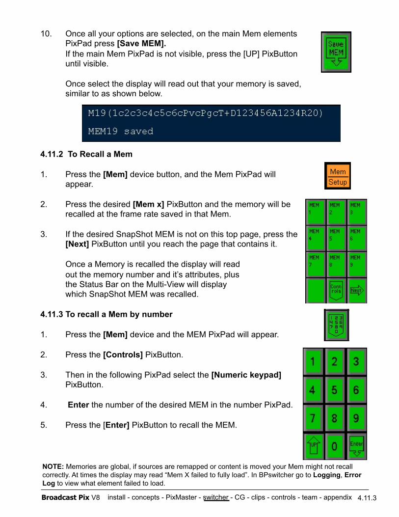
install - concepts - PixMaster - switcher - CG - clips - controls - team - appendix Broadcast Pix V8 4.11.3
10. Once all your options are selected, on the main Mem elements PixPad press [Save MEM]. If the main Mem PixPad is not visible, press the [UP] PixButton until visible.
Once select the display will read out that your memory is saved, similar to as shown below.
4.11.2 To Recall a Mem
1. Press the [Mem] device button, and the Mem PixPad will appear.
2. Press the desired [Mem x] PixButton and the memory will be recalled at the frame rate saved in that Mem.
3. If the desired SnapShot MEM is not on this top page, press the [Next] PixButton until you reach the page that contains it.
Once a Memory is recalled the display will read out the memory number and it’s attributes, plus the Status Bar on the Multi-View will display which SnapShot MEM was recalled.
4.11.3 To recall a Mem by number
1. Press the [Mem] device and the MEM PixPad will appear.
2. Press the [Controls] PixButton.
3. Then in the following PixPad select the [Numeric keypad] PixButton.
4. Enter the number of the desired MEM in the number PixPad.
5. Press the [Enter] PixButton to recall the MEM.
NOTE: Memories are global, if sources are remapped or content is moved your Mem might not recall correctly. At times the display may read “Mem X failed to fully load”. In BPswitcher go to Logging, Error Log to view what element failed to load.
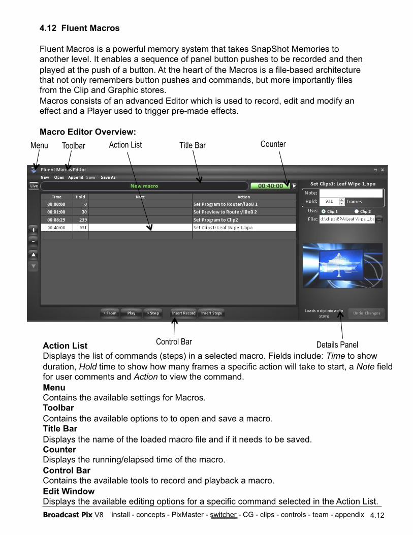
install - concepts - PixMaster - switcher - CG - clips - controls - team - appendix Broadcast Pix V8 4.12
4.12 Fluent Macros
Fluent Macros is a powerful memory system that takes SnapShot Memories to another level. It enables a sequence of panel button pushes to be recorded and then played at the push of a button. At the heart of the Macros is a file-based architecture that not only remembers button pushes and commands, but more importantly files from the Clip and Graphic stores. Macros consists of an advanced Editor which is used to record, edit and modify an effect and a Player used to trigger pre-made effects.
Macro Editor Overview:
Action List Displays the list of commands (steps) in a selected macro. Fields include: Time to show duration, Hold time to show how many frames a specific action will take to start, a Note field for user comments and Action to view the command. Menu Contains the available settings for Macros. Toolbar Contains the available options to to open and save a macro. Title Bar Displays the name of the loaded macro file and if it needs to be saved. Counter Displays the running/elapsed time of the macro. Control Bar Contains the available tools to record and playback a macro. Edit Window Displays the available editing options for a specific command selected in the Action List.
Counter Menu Action List
Control Bar Details Panel
Title Bar Toolbar
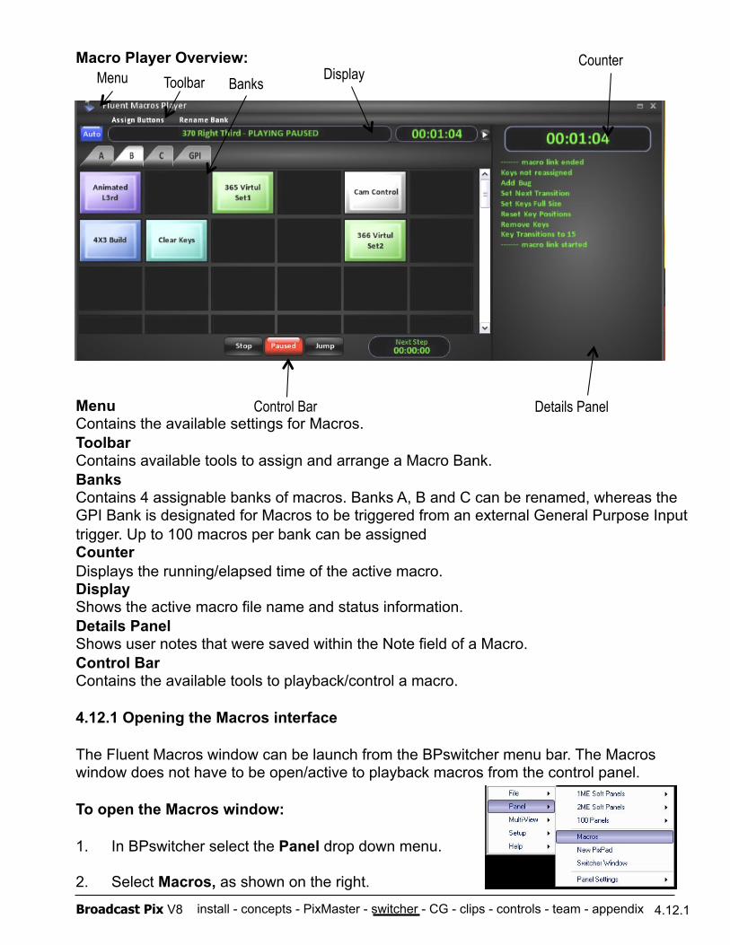
install - concepts - PixMaster - switcher - CG - clips - controls - team - appendix Broadcast Pix V8 4.12.1
Macro Player Overview: Counter Menu
Control Bar
Display
Details Panel Menu Contains the available settings for Macros. Toolbar Contains available tools to assign and arrange a Macro Bank. Banks Contains 4 assignable banks of macros. Banks A, B and C can be renamed, whereas the GPI Bank is designated for Macros to be triggered from an external General Purpose Input trigger. Up to 100 macros per bank can be assigned Counter Displays the running/elapsed time of the active macro. Display Shows the active macro file name and status information. Details Panel Shows user notes that were saved within the Note field of a Macro. Control Bar Contains the available tools to playback/control a macro.
4.12.1 Opening the Macros interface
The Fluent Macros window can be launch from the BPswitcher menu bar. The Macros window does not have to be open/active to playback macros from the control panel.
To open the Macros window:
1. In BPswitcher select the Panel drop down menu.
2. Select Macros, as shown on the right.
Toolbar Banks
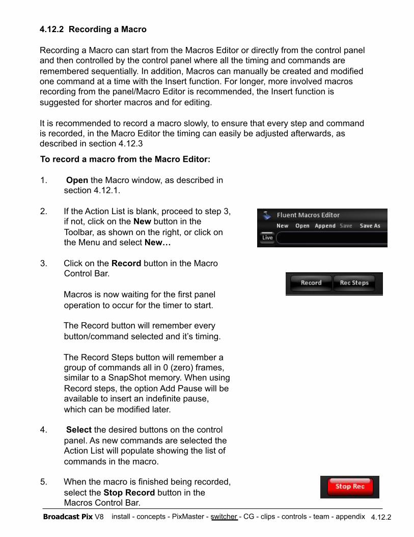
install - concepts - PixMaster - switcher - CG - clips - controls - team - appendix Broadcast Pix V8 4.12.2
4.12.2 Recording a Macro
Recording a Macro can start from the Macros Editor or directly from the control panel and then controlled by the control panel where all the timing and commands are remembered sequentially. In addition, Macros can manually be created and modified one command at a time with the Insert function. For longer, more involved macros recording from the panel/Macro Editor is recommended, the Insert function is suggested for shorter macros and for editing.
It is recommended to record a macro slowly, to ensure that every step and command is recorded, in the Macro Editor the timing can easily be adjusted afterwards, as described in section 4.12.3
To record a macro from the Macro Editor:
1. Open the Macro window, as described in section 4.12.1.
2. If the Action List is blank, proceed to step 3, if not, click on the New button in the Toolbar, as shown on the right, or click on the Menu and select New…
3. Click on the Record button in the Macro Control Bar.
Macros is now waiting for the first panel operation to occur for the timer to start.
The Record button will remember every button/command selected and it’s timing.
The Record Steps button will remember a group of commands all in 0 (zero) frames, similar to a SnapShot memory. When using Record steps, the option Add Pause will be available to insert an indefinite pause, which can be modified later.
4. Select the desired buttons on the control panel. As new commands are selected the Action List will populate showing the list of commands in the macro.
5. When the macro is finished being recorded, select the Stop Record button in the Macros Control Bar.
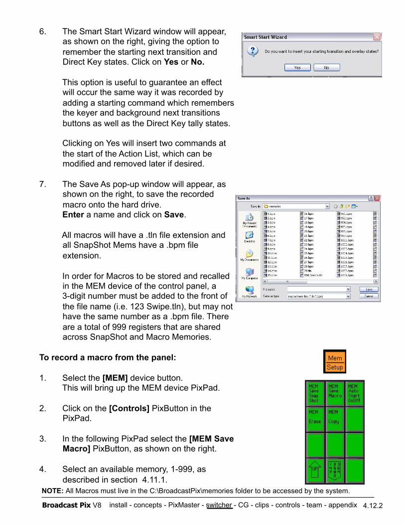
install - concepts - PixMaster - switcher - CG - clips - controls - team - appendix Broadcast Pix V8 4.12.2
6. The Smart Start Wizard window will appear, as shown on the right, giving the option to remember the starting next transition and Direct Key states. Click on Yes or No.
This option is useful to guarantee an effect will occur the same way it was recorded by adding a starting command which remembers the keyer and background next transitions buttons as well as the Direct Key tally states.
Clicking on Yes will insert two commands at the start of the Action List, which can be modified and removed later if desired.
7. The Save As pop-up window will appear, as shown on the right, to save the recorded macro onto the hard drive.
Enter a name and click on Save.
All macros will have a .tln file extension and all SnapShot Mems have a .bpm file extension.
In order for Macros to be stored and recalled in the MEM device of the control panel, a
3-digit number must be added to the front of the file name (i.e. 123 Swipe.tln), but may not have the same number as a .bpm file. There are a total of 999 registers that are shared across SnapShot and Macro Memories.
To record a macro from the panel:
1. Select the [MEM] device button. This will bring up the MEM device PixPad.
2. Click on the [Controls] PixButton in the PixPad.
3. In the following PixPad select the [MEM Save Macro] PixButton, as shown on the right.
4. Select an available memory, 1-999, as described in section 4.11.1.
NOTE: All Macros must live in the C:\BroadcastPix\memories folder to be accessed by the system.

install - concepts - PixMaster - switcher - CG - clips - controls - team - appendix Broadcast Pix V8 4.12.2
5. In the following PixPad select the [MEM Start Record] PixButton, as shown on the right.
Note that the Macro Editor or Player does not need to be opened for recording to occur. However, if the Macro Player is open a list of commands being recorded will be visible in the Macro Display.
Macros is now waiting for the first panel operation to occur for the timer to start.
The Record button will remember every button/command selected and it’s timing sequentially.
6. Select the desired buttons on the control panel.
The display will read out that the Macro is recording, the counter in the lower right corner will start to move and the Play motion control button will illuminate red.
7. When the macro is finished being recorded, select the [MEM] device button, it will illuminate orange.
8. Select the [Back] motion control button to stop the recording, as shown on the right.
The Play motion control button will turn off and the display will read out Recording ended.
4.12.3 Editing a Macro
The Macro Editor can display only one active macro at time, allowing for only one macro to be edited at a time. After a macro has been recorded it can be opened in the Macro Editor to be modified. Once in the Editor, the Action List may be reordered and modified, new commands can be inserted and the timing of each command can be adjusted. All the editing is done in the Macro Editor with the keyboard and mouse.
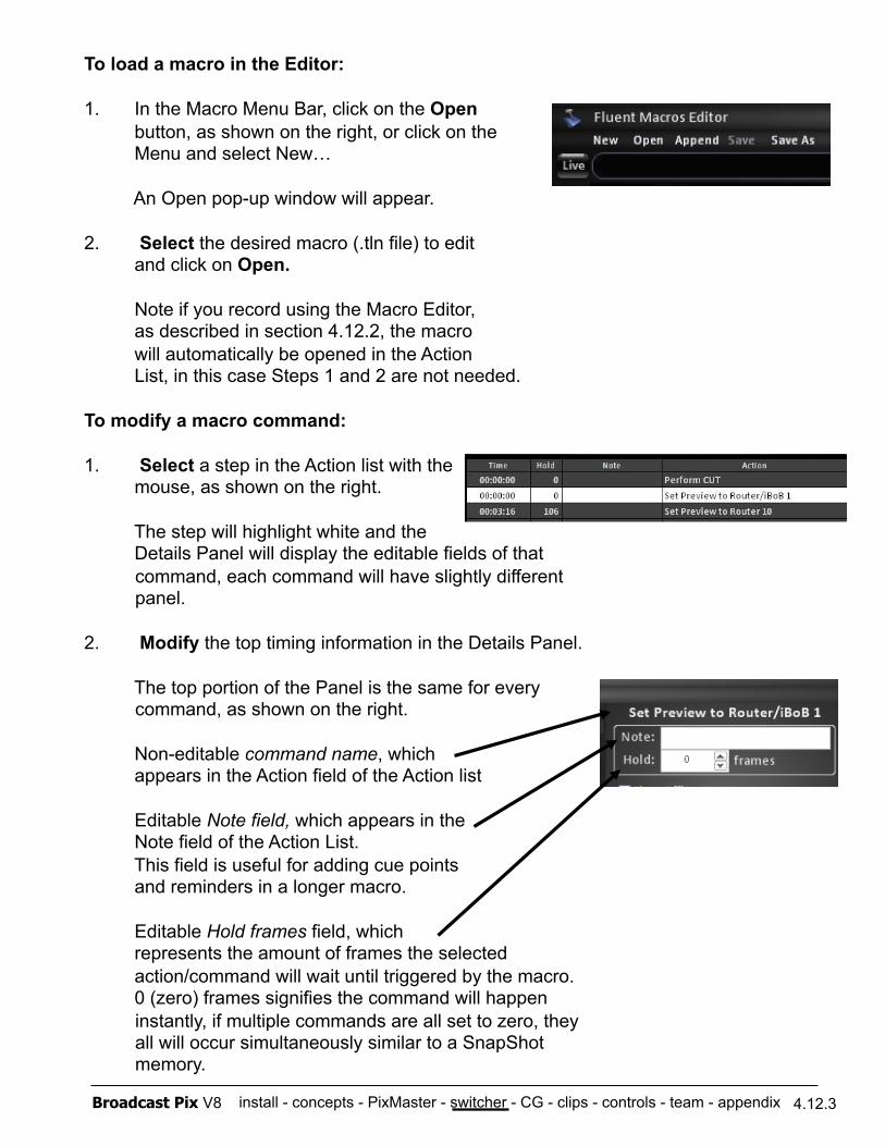
install - concepts - PixMaster - switcher - CG - clips - controls - team - appendix Broadcast Pix V8 4.12.3
To load a macro in the Editor:
1. In the Macro Menu Bar, click on the Open button, as shown on the right, or click on the Menu and select New…
An Open pop-up window will appear.
2. Select the desired macro (.tln file) to edit and click on Open.
Note if you record using the Macro Editor, as described in section 4.12.2, the macro will automatically be opened in the Action List, in this case Steps 1 and 2 are not needed.
To modify a macro command:
1. Select a step in the Action list with the mouse, as shown on the right.
The step will highlight white and the Details Panel will display the editable fields of that command, each command will have slightly different panel.
2. Modify the top timing information in the Details Panel.
The top portion of the Panel is the same for every command, as shown on the right.
Non-editable command name, which appears in the Action field of the Action list
Editable Note field, which appears in the Note field of the Action List. This field is useful for adding cue points and reminders in a longer macro.
Editable Hold frames field, which represents the amount of frames the selected action/command will wait until triggered by the macro. 0 (zero) frames signifies the command will happen instantly, if multiple commands are all set to zero, they all will occur simultaneously similar to a SnapShot memory.
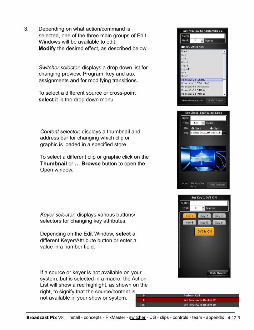
install - concepts - PixMaster - switcher - CG - clips - controls - team - appendix Broadcast Pix V8 4.12.3
3. Depending on what action/command is selected, one of the three main groups of Edit Windows will be available to edit.
Modify the desired effect, as described below.
Switcher selector: displays a drop down list for changing preview, Program, key and aux assignments and for modifying transitions.
To select a different source or cross-point select it in the drop down menu.
Content selector: displays a thumbnail and address bar for changing which clip or graphic is loaded in a specified store.
To select a different clip or graphic click on the Thumbnail or … Browse button to open the Open window.
Keyer selector, displays various buttons/ selectors for changing key attributes.
Depending on the Edit Window, select a different Keyer/Attribute button or enter a value in a number field.
If a source or keyer is not available on your system, but is selected in a macro, the Action List will show a red highlight, as shown on the right, to signify that the source/content is not available in your show or system.
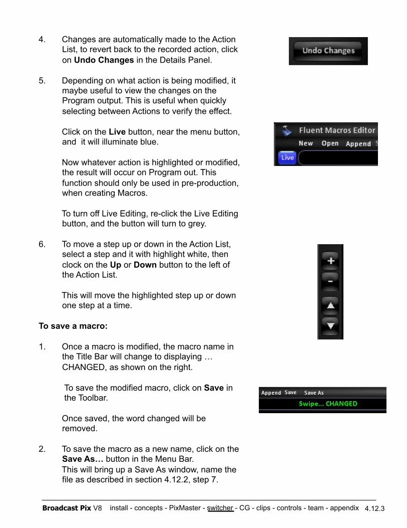
install - concepts - PixMaster - switcher - CG - clips - controls - team - appendix Broadcast Pix V8 4.12.3
4. Changes are automatically made to the Action List, to revert back to the recorded action, click on Undo Changes in the Details Panel.
5. Depending on what action is being modified, it maybe useful to view the changes on the Program output. This is useful when quickly selecting between Actions to verify the effect.
Click on the Live button, near the menu button, and it will illuminate blue.
Now whatever action is highlighted or modified, the result will occur on Program out. This function should only be used in pre-production, when creating Macros.
To turn off Live Editing, re-click the Live Editing button, and the button will turn to grey.
6. To move a step up or down in the Action List, select a step and it with highlight white, then clock on the Up or Down button to the left of the Action List.
This will move the highlighted step up or down one step at a time.
To save a macro:
1. Once a macro is modified, the macro name in the Title Bar will change to displaying …CHANGED, as shown on the right.
To save the modified macro, click on Save in the Toolbar.
Once saved, the word changed will be removed.
2. To save the macro as a new name, click on the Save As… button in the Menu Bar.
This will bring up a Save As window, name the file as described in section 4.12.2, step 7.
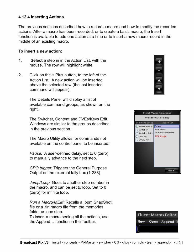
install - concepts - PixMaster - switcher - CG - clips - controls - team - appendix Broadcast Pix V8 4.12.4
4.12.4 Inserting Actions
The previous sections described how to record a macro and how to modify the recorded actions. After a macro has been recorded, or to create a basic macro, the Insert function is available to add one action at a time or to insert a new macro record in the middle of an existing macro.
To insert a new action:
1. Select a step in in the Action List, with the mouse. The row will highlight white.
2. Click on the + Plus button, to the left of the Action List. A new action will be inserted above the selected row (the last inserted command will appear).
The Details Panel will display a list of available command groups, as shown on the right.
The Switcher, Content and DVEs/Keys Edit Windows are similar to the groups described in the previous section.
The Macro Utility allows for commands not available on the control panel to be inserted:
Pause: A user-defined delay, set to 0 (zero) to manually advance to the next step.
GPO trigger: Triggers the General Purpose Output on the external tally box (1-288)
Jump/Loop: Goes to another step number in the macro, and can be set to loop. Set to 0 (zero) for infinite loop.
Run a Macro/MEM: Recalls a .bpm SnapShot file or a .tln macro file from the memories folder as one step.
To insert a macro seeing all the actions, use the Append… function in the Toolbar.
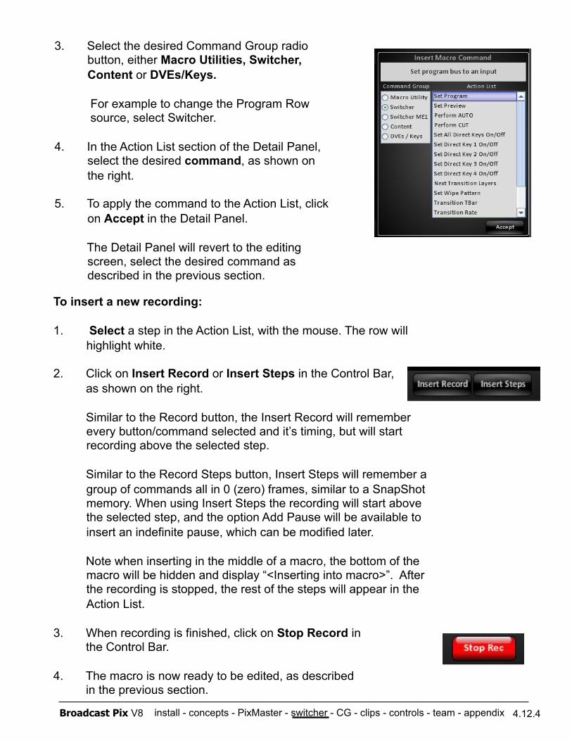
install - concepts - PixMaster - switcher - CG - clips - controls - team - appendix Broadcast Pix V8 4.12.4
3. Select the desired Command Group radio button, either Macro Utilities, Switcher, Content or DVEs/Keys.
For example to change the Program Row source, select Switcher.
4. In the Action List section of the Detail Panel, select the desired command, as shown on the right.
5. To apply the command to the Action List, click on Accept in the Detail Panel.
The Detail Panel will revert to the editing screen, select the desired command as described in the previous section.
To insert a new recording:
1. Select a step in the Action List, with the mouse. The row will highlight white.
2. Click on Insert Record or Insert Steps in the Control Bar, as shown on the right.
Similar to the Record button, the Insert Record will remember every button/command selected and it’s timing, but will start recording above the selected step.
Similar to the Record Steps button, Insert Steps will remember a group of commands all in 0 (zero) frames, similar to a SnapShot memory. When using Insert Steps the recording will start above the selected step, and the option Add Pause will be available to insert an indefinite pause, which can be modified later.
Note when inserting in the middle of a macro, the bottom of the macro will be hidden and display “<Inserting into macro>”. After the recording is stopped, the rest of the steps will appear in the Action List.
3. When recording is finished, click on Stop Record in the Control Bar.
4. The macro is now ready to be edited, as described in the previous section.
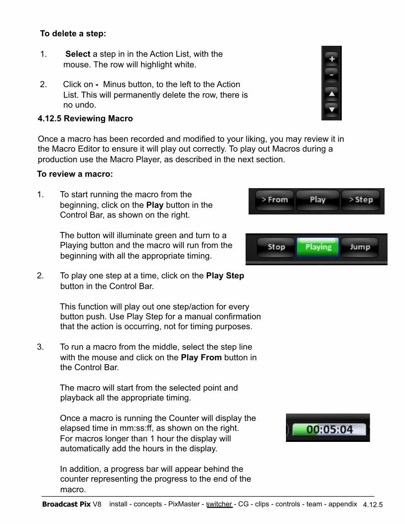
install - concepts - PixMaster - switcher - CG - clips - controls - team - appendix Broadcast Pix V8 4.12.5
4.12.5 Reviewing Macro
Once a macro has been recorded and modified to your liking, you may review it in the Macro Editor to ensure it will play out correctly. To play out Macros during a production use the Macro Player, as described in the next section.
To review a macro:
1. To start running the macro from the beginning, click on the Play button in the Control Bar, as shown on the right.
The button will illuminate green and turn to a Playing button and the macro will run from the beginning with all the appropriate timing.
2. To play one step at a time, click on the Play Step button in the Control Bar.
This function will play out one step/action for every button push. Use Play Step for a manual confirmation that the action is occurring, not for timing purposes.
3. To run a macro from the middle, select the step line with the mouse and click on the Play From button in the Control Bar.
The macro will start from the selected point and playback all the appropriate timing.
Once a macro is running the Counter will display the elapsed time in mm:ss:ff, as shown on the right.
For macros longer than 1 hour the display will automatically add the hours in the display.
In addition, a progress bar will appear behind the counter representing the progress to the end of the macro.
To delete a step:
1. Select a step in in the Action List, with the mouse. The row will highlight white.
2. Click on - Minus button, to the left to the Action List. This will permanently delete the row, there is no undo.
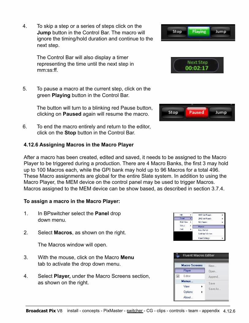
install - concepts - PixMaster - switcher - CG - clips - controls - team - appendix Broadcast Pix V8 4.12.6
4. To skip a step or a series of steps click on the Jump button in the Control Bar. The macro will ignore the timing/hold duration and continue to the next step.
The Control Bar will also display a timer representing the time until the next step in mm:ss:ff.
5. To pause a macro at the current step, click on the green Playing button in the Control Bar.
The button will turn to a blinking red Pause button, clicking on Paused again will resume the macro.
6. To end the macro entirely and return to the editor, click on the Stop button in the Control Bar.
4.12.6 Assigning Macros in the Macro Player
After a macro has been created, edited and saved, it needs to be assigned to the Macro Player to be triggered during a production. There are 4 Macro Banks, the first 3 may hold up to 100 Macros each, while the GPI bank may hold up to 96 Macros for a total 496. These Macro assignments are global for the entire Slate system. In addition to using the Macro Player, the MEM device on the control panel may be used to trigger Macros. Macros assigned to the MEM device can be show based, as described in section 3.7.4.
To assign a macro in the Macro Player:
1. In BPswitcher select the Panel drop down menu.
2. Select Macros, as shown on the right.
The Macros window will open.
3. With the mouse, click on the Macro Menu tab to activate the drop down menu.
4. Select Player, under the Macro Screens section, as shown on the right.
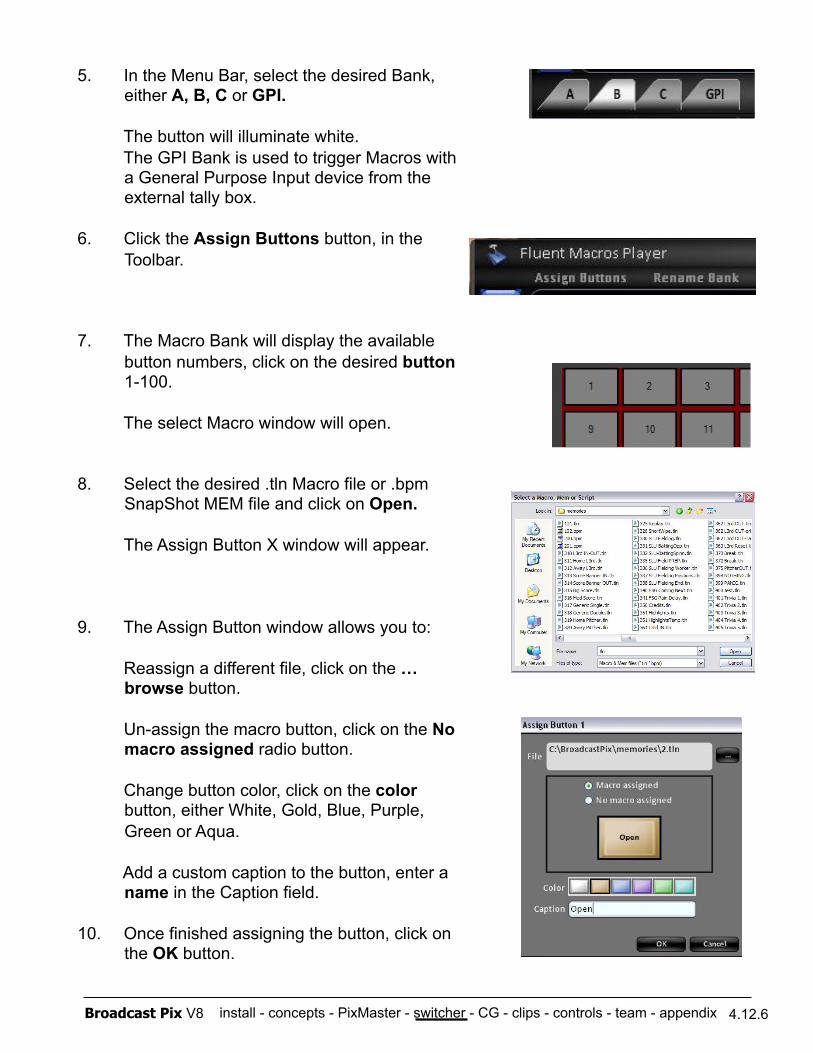
install - concepts - PixMaster - switcher - CG - clips - controls - team - appendix Broadcast Pix V8 4.12.6
5. In the Menu Bar, select the desired Bank, either A, B, C or GPI.
The button will illuminate white. The GPI Bank is used to trigger Macros with a General Purpose Input device from the external tally box.
6. Click the Assign Buttons button, in the Toolbar.
7. The Macro Bank will display the available button numbers, click on the desired button 1-100.
The select Macro window will open.
8. Select the desired .tln Macro file or .bpm SnapShot MEM file and click on Open.
The Assign Button X window will appear.
9. The Assign Button window allows you to:
Reassign a different file, click on the … browse button.
Un-assign the macro button, click on the No macro assigned radio button.
Change button color, click on the color button, either White, Gold, Blue, Purple, Green or Aqua.
Add a custom caption to the button, enter a name in the Caption field.
10. Once finished assigning the button, click on the OK button.
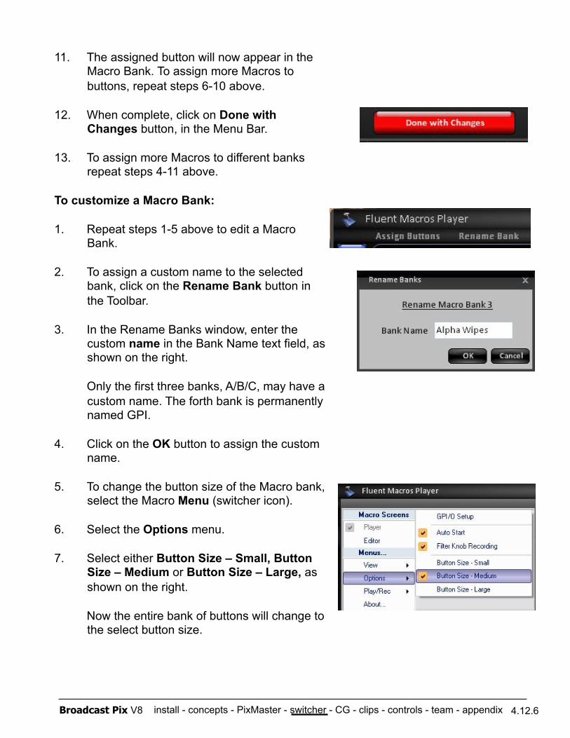
install - concepts - PixMaster - switcher - CG - clips - controls - team - appendix Broadcast Pix V8 4.12.6
11. The assigned button will now appear in the Macro Bank. To assign more Macros to buttons, repeat steps 6-10 above.
12. When complete, click on Done with Changes button, in the Menu Bar.
13. To assign more Macros to different banks repeat steps 4-11 above.
To customize a Macro Bank:
1. Repeat steps 1-5 above to edit a Macro Bank.
2. To assign a custom name to the selected bank, click on the Rename Bank button in the Toolbar.
3. In the Rename Banks window, enter the custom name in the Bank Name text field, as shown on the right.
Only the first three banks, A/B/C, may have a custom name. The forth bank is permanently named GPI.
4. Click on the OK button to assign the custom name.
5. To change the button size of the Macro bank, select the Macro Menu (switcher icon).
6. Select the Options menu.
7. Select either Button Size – Small, Button Size – Medium or Button Size – Large, as shown on the right.
Now the entire bank of buttons will change to the select button size.
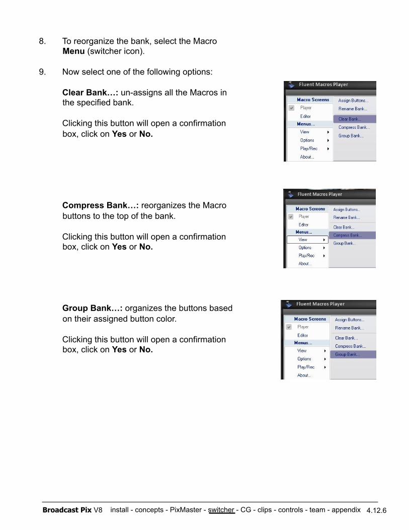
install - concepts - PixMaster - switcher - CG - clips - controls - team - appendix Broadcast Pix V8 4.12.6
8. To reorganize the bank, select the Macro Menu (switcher icon).
9. Now select one of the following options:
Clear Bank…: un-assigns all the Macros in the specified bank.
Clicking this button will open a confirmation box, click on Yes or No.
Compress Bank…: reorganizes the Macro buttons to the top of the bank.
Clicking this button will open a confirmation box, click on Yes or No.
Group Bank…: organizes the buttons based on their assigned button color.
Clicking this button will open a confirmation box, click on Yes or No.
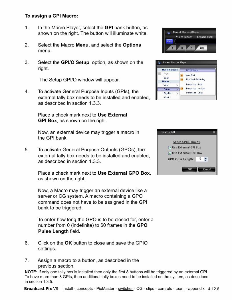
install - concepts - PixMaster - switcher - CG - clips - controls - team - appendix Broadcast Pix V8 4.12.6
To assign a GPI Macro:
1. In the Macro Player, select the GPI bank button, as shown on the right. The button will illuminate white.
2. Select the Macro Menu, and select the Options menu.
3. Select the GPI/O Setup option, as shown on the right.
The Setup GPI/O window will appear.
4. To activate General Purpose Inputs (GPIs), the external tally box needs to be installed and enabled, as described in section 1.3.3.
Place a check mark next to Use External GPI Box, as shown on the right.
Now, an external device may trigger a macro in the GPI bank.
5. To activate General Purpose Outputs (GPOs), the external tally box needs to be installed and enabled, as described in section 1.3.3.
Place a check mark next to Use External GPO Box, as shown on the right.
Now, a Macro may trigger an external device like a server or CG system. A macro containing a GPO command does not have to be assigned in the GPI bank to be triggered.
To enter how long the GPO is to be closed for, enter a number from 0 (indefinite) to 60 frames in the GPO Pulse Length field.
6. Click on the OK button to close and save the GPIO settings.
7. Assign a macro to a button, as described in the previous section.
NOTE: If only one tally box is installed then only the first 8 buttons will be triggered by an external GPI. To have more than 8 GPIs, then additional tally boxes need to be installed on the system, as described in section 1.3.5.
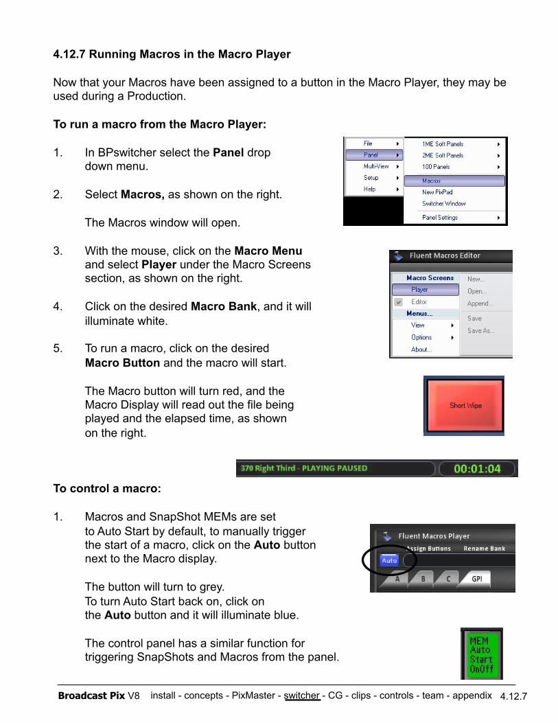
install - concepts - PixMaster - switcher - CG - clips - controls - team - appendix Broadcast Pix V8 4.12.7
4.12.7 Running Macros in the Macro Player
Now that your Macros have been assigned to a button in the Macro Player, they may be used during a Production.
To run a macro from the Macro Player:
1. In BPswitcher select the Panel drop down menu.
2. Select Macros, as shown on the right.
The Macros window will open.
3. With the mouse, click on the Macro Menu and select Player under the Macro Screens section, as shown on the right.
4. Click on the desired Macro Bank, and it will illuminate white.
5. To run a macro, click on the desired Macro Button and the macro will start.
The Macro button will turn red, and the Macro Display will read out the file being played and the elapsed time, as shown on the right.
To control a macro:
1. Macros and SnapShot MEMs are set to Auto Start by default, to manually trigger the start of a macro, click on the Auto button next to the Macro display.
The button will turn to grey. To turn Auto Start back on, click on the Auto button and it will illuminate blue.
The control panel has a similar function for triggering SnapShots and Macros from the panel.
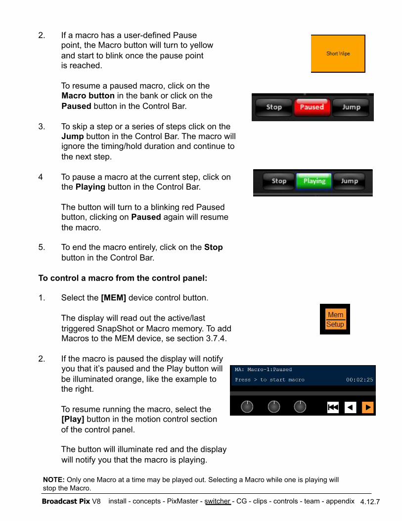
install - concepts - PixMaster - switcher - CG - clips - controls - team - appendix Broadcast Pix V8 4.12.7
2. If a macro has a user-defined Pause point, the Macro button will turn to yellow and start to blink once the pause point is reached.
To resume a paused macro, click on the Macro button in the bank or click on the Paused button in the Control Bar.
3. To skip a step or a series of steps click on the Jump button in the Control Bar. The macro will ignore the timing/hold duration and continue to the next step.
4 To pause a macro at the current step, click on the Playing button in the Control Bar.
The button will turn to a blinking red Paused button, clicking on Paused again will resume the macro.
5. To end the macro entirely, click on the Stop button in the Control Bar.
To control a macro from the control panel:
1. Select the [MEM] device control button.
The display will read out the active/last triggered SnapShot or Macro memory. To add Macros to the MEM device, se section 3.7.4.
2. If the macro is paused the display will notify you that it’s paused and the Play button will
be illuminated orange, like the example to the right.
To resume running the macro, select the [Play] button in the motion control section
of the control panel.
The button will illuminate red and the display will notify you that the macro is playing.
NOTE: Only one Macro at a time may be played out. Selecting a Macro while one is playing will stop the Macro.
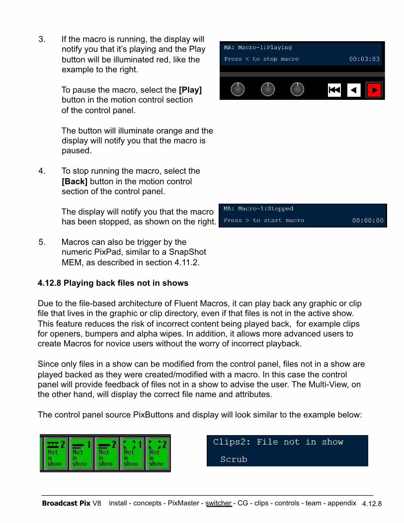
install - concepts - PixMaster - switcher - CG - clips - controls - team - appendix Broadcast Pix V8 4.12.8
3. If the macro is running, the display will notify you that it’s playing and the Play button will be illuminated red, like the example to the right.
To pause the macro, select the [Play] button in the motion control section
of the control panel.
The button will illuminate orange and the display will notify you that the macro is paused.
4. To stop running the macro, select the [Back] button in the motion control section of the control panel.
The display will notify you that the macro has been stopped, as shown on the right.
5. Macros can also be trigger by the numeric PixPad, similar to a SnapShot MEM, as described in section 4.11.2.
4.12.8 Playing back files not in shows
Due to the file-based architecture of Fluent Macros, it can play back any graphic or clip file that lives in the graphic or clip directory, even if that files is not in the active show. This feature reduces the risk of incorrect content being played back, for example clips for openers, bumpers and alpha wipes. In addition, it allows more advanced users to create Macros for novice users without the worry of incorrect playback.
Since only files in a show can be modified from the control panel, files not in a show are played backed as they were created/modified with a macro. In this case the control panel will provide feedback of files not in a show to advise the user. The Multi-View, on the other hand, will display the correct file name and attributes.
The control panel source PixButtons and display will look similar to the example below:
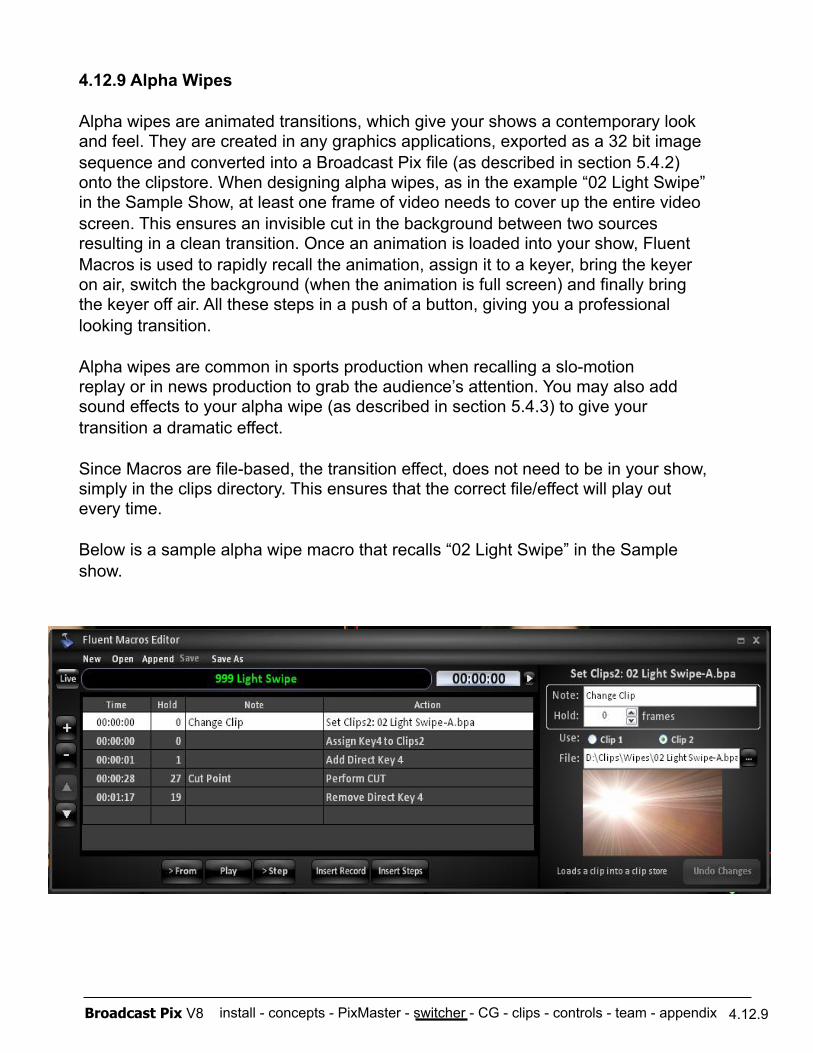
install - concepts - PixMaster - switcher - CG - clips - controls - team - appendix Broadcast Pix V8 4.12.9
4.12.9 Alpha Wipes
Alpha wipes are animated transitions, which give your shows a contemporary look and feel. They are created in any graphics applications, exported as a 32 bit image sequence and converted into a Broadcast Pix file (as described in section 5.4.2) onto the clipstore. When designing alpha wipes, as in the example “02 Light Swipe” in the Sample Show, at least one frame of video needs to cover up the entire video screen. This ensures an invisible cut in the background between two sources resulting in a clean transition. Once an animation is loaded into your show, Fluent Macros is used to rapidly recall the animation, assign it to a keyer, bring the keyer on air, switch the background (when the animation is full screen) and finally bring the keyer off air. All these steps in a push of a button, giving you a professional looking transition.
Alpha wipes are common in sports production when recalling a slo-motion replay or in news production to grab the audience’s attention. You may also add sound effects to your alpha wipe (as described in section 5.4.3) to give your transition a dramatic effect.
Since Macros are file-based, the transition effect, does not need to be in your show, simply in the clips directory. This ensures that the correct file/effect will play out every time.
Below is a sample alpha wipe macro that recalls “02 Light Swipe” in the Sample show.
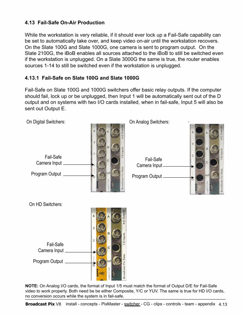
install - concepts - PixMaster - switcher - CG - clips - controls - team - appendix Broadcast Pix V8
4.13 Fail-Safe On-Air Production
While the workstation is very reliable, if it should ever lock up a Fail-Safe capability can be set to automatically take over, and keep video on-air until the workstation recovers. On the Slate 100G and Slate 1000G, one camera is sent to program output. On the Slate 2100G, the iBoB enables all sources attached to the iBoB to still be switched even if the workstation is unplugged. On a Slate 3000G the same is true, the router enables sources 1-14 to still be switched even if the workstation is unplugged.
4.13.1 Fail-Safe on Slate 100G and Slate 1000G
Fail-Safe on Slate 100G and 1000G switchers offer basic relay outputs. If the computer should fail, lock up or be unplugged, then Input 1 will be automatically sent out of the D output and on systems with two I/O cards installed, when in fail-safe, Input 5 will also be sent out Output E.
4.13
Program Output
Fail-Safe Camera Input
On Digital Switchers: On Analog Switchers:
NOTE: On Analog I/O cards, the format of Input 1/5 must match the format of Output D/E for Fail-Safe video to work properly. Both need be be either Composite, Y/C or YUV. The same is true for HD I/O cards, no conversion occurs while the system is in fail-safe.
Program Output
Fail-Safe Camera Input
On HD Switchers:
Program Output
Fail-Safe Camera Input
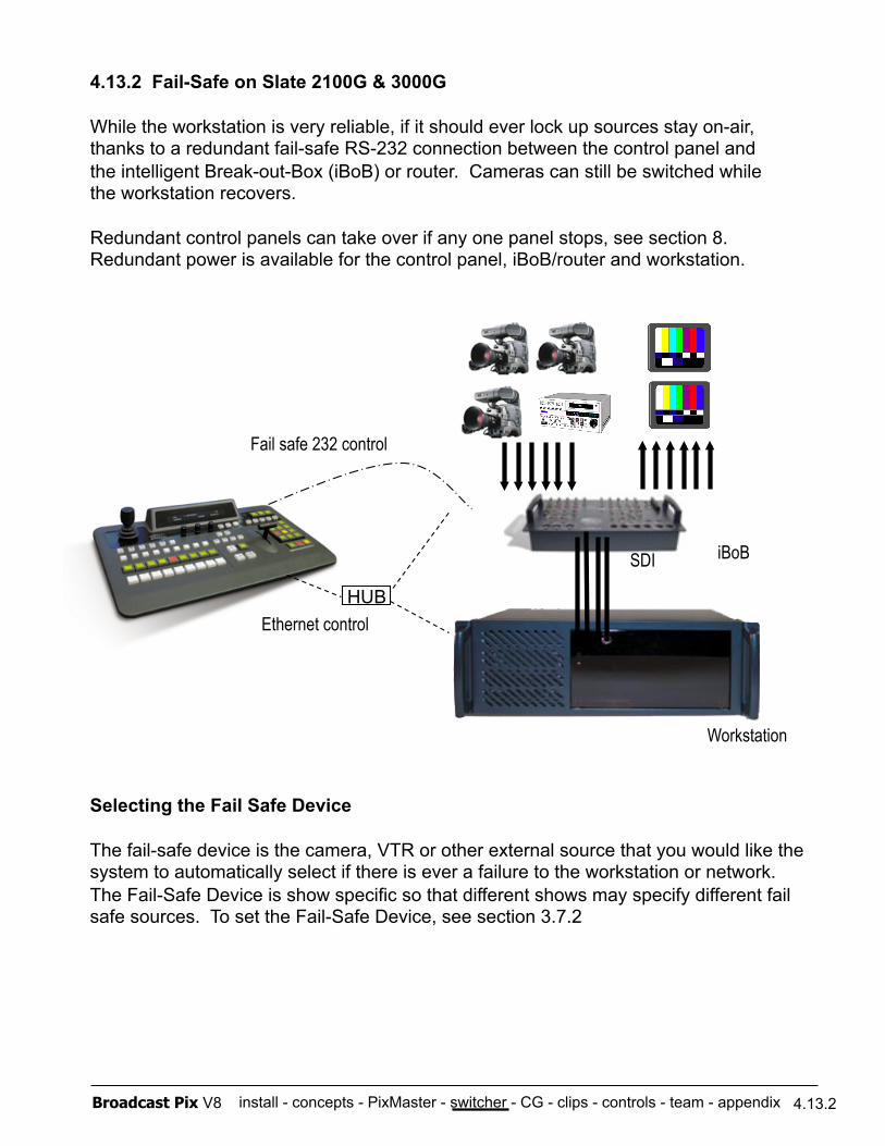
install - concepts - PixMaster - switcher - CG - clips - controls - team - appendix Broadcast Pix V8
4.13.2 Fail-Safe on Slate 2100G & 3000G
While the workstation is very reliable, if it should ever lock up sources stay on-air, thanks to a redundant fail-safe RS-232 connection between the control panel and the intelligent Break-out-Box (iBoB) or router. Cameras can still be switched while the workstation recovers.
Redundant control panels can take over if any one panel stops, see section 8. Redundant power is available for the control panel, iBoB/router and workstation.
Ethernet control
Fail safe 232 control
SDI iBoB
HUB
Workstation
4.13.2
Selecting the Fail Safe Device
The fail-safe device is the camera, VTR or other external source that you would like the system to automatically select if there is ever a failure to the workstation or network. The Fail-Safe Device is show specific so that different shows may specify different fail safe sources. To set the Fail-Safe Device, see section 3.7.2
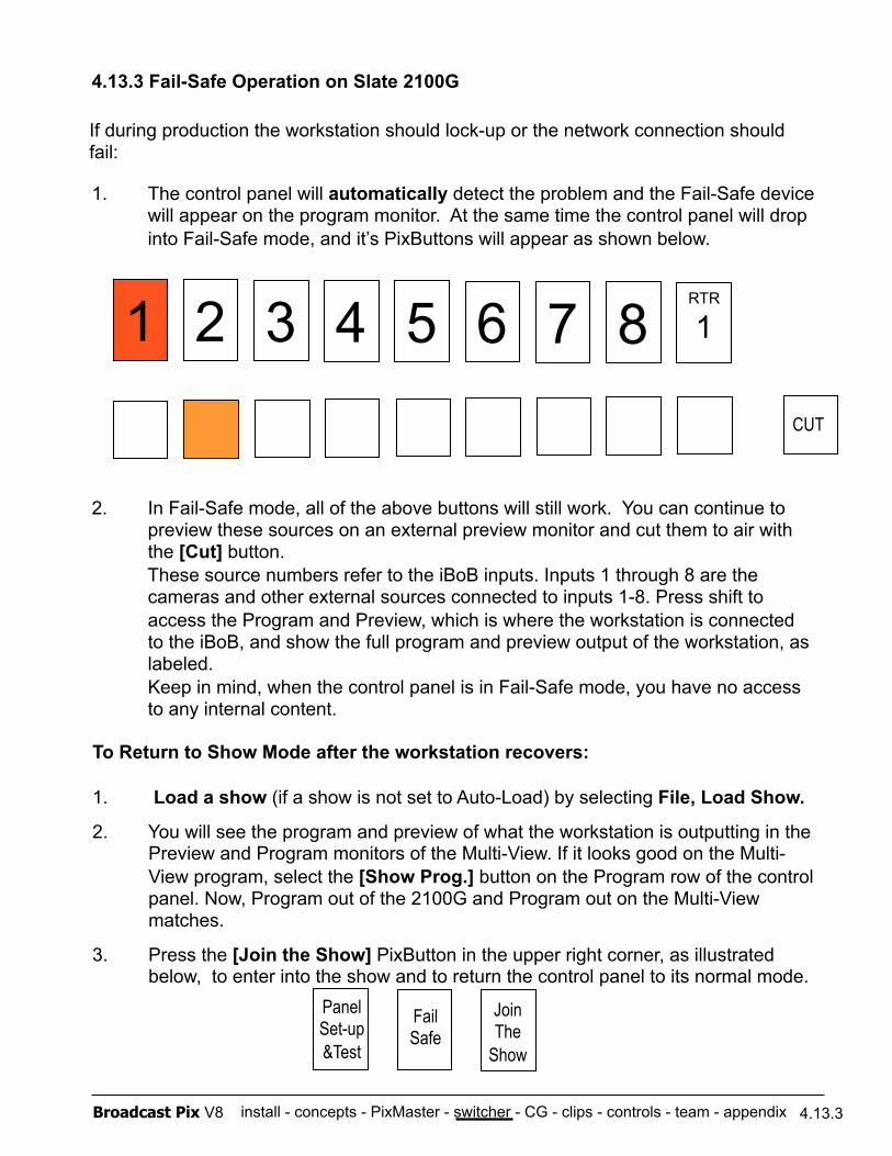
install - concepts - PixMaster - switcher - CG - clips - controls - team - appendix Broadcast Pix V8
4.13.3 Fail-Safe Operation on Slate 2100G
1. The control panel will automatically detect the problem and the Fail-Safe device will appear on the program monitor. At the same time the control panel will drop into Fail-Safe mode, and it’s PixButtons will appear as shown below.
2. In Fail-Safe mode, all of the above buttons will still work. You can continue to preview these sources on an external preview monitor and cut them to air with the [Cut] button. These source numbers refer to the iBoB inputs. Inputs 1 through 8 are the cameras and other external sources connected to inputs 1-8. Press shift to access the Program and Preview, which is where the workstation is connected to the iBoB, and show the full program and preview output of the workstation, as labeled. Keep in mind, when the control panel is in Fail-Safe mode, you have no access to any internal content.
1 2 3 4 5 6 7 8 RTR
1
CUT
Fail Safe
Join The
Show
Panel Set-up &Test
To Return to Show Mode after the workstation recovers:
1. Load a show (if a show is not set to Auto-Load) by selecting File, Load Show.
2. You will see the program and preview of what the workstation is outputting in the Preview and Program monitors of the Multi-View. If it looks good on the Multi-View program, select the [Show Prog.] button on the Program row of the control panel. Now, Program out of the 2100G and Program out on the Multi-View matches.
3. Press the [Join the Show] PixButton in the upper right corner, as illustrated below, to enter into the show and to return the control panel to its normal mode.
4.13.3
If during production the workstation should lock-up or the network connection should fail:
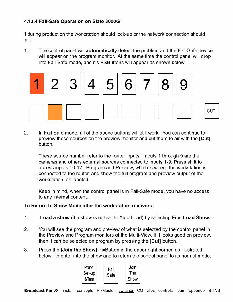
install - concepts - PixMaster - switcher - CG - clips - controls - team - appendix Broadcast Pix V8
4.13.4 Fail-Safe Operation on Slate 3000G
1. The control panel will automatically detect the problem and the Fail-Safe device will appear on the program monitor. At the same time the control panel will drop into Fail-Safe mode, and it’s PixButtons will appear as shown below.
2. In Fail-Safe mode, all of the above buttons will still work. You can continue to preview these sources on the preview monitor and cut them to air with the [Cut] button.
These source number refer to the router inputs. Inputs 1 through 9 are the cameras and others external sources connected to inputs 1-9. Press shift to access inputs 10-12, Program and Preview, which is where the workstation is connected to the router, and show the full program and preview output of the workstation, as labeled.
Keep in mind, when the control panel is in Fail-Safe mode, you have no access to any internal content.
1 2 3 4 5 6 7 8 9 CUT
Fail Safe
Join The
Show
Panel Set-up &Test
To Return to Show Mode after the workstation recovers:
1. Load a show (if a show is not set to Auto-Load) by selecting File, Load Show.
2. You will see the program and preview of what is selected by the control panel in the Preview and Program monitors of the Multi-View. If it looks good on preview, then it can be selected on program by pressing the [Cut] button.
3. Press the [Join the Show] PixButton in the upper right corner, as illustrated below, to enter into the show and to return the control panel to its normal mode.
4.13.4
If during production the workstation should lock-up or the network connection should fail:
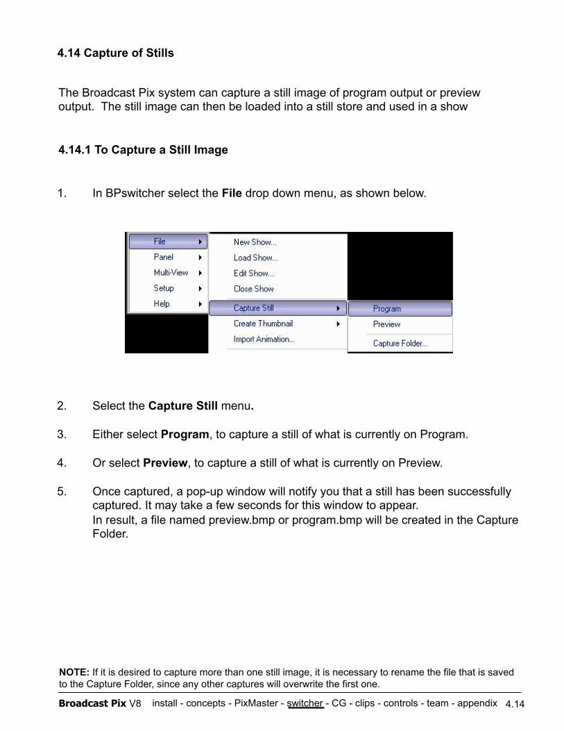
install - concepts - PixMaster - switcher - CG - clips - controls - team - appendix Broadcast Pix V8
1. In BPswitcher select the File drop down menu, as shown below.
2. Select the Capture Still menu.
3. Either select Program, to capture a still of what is currently on Program.
4. Or select Preview, to capture a still of what is currently on Preview.
5. Once captured, a pop-up window will notify you that a still has been successfully captured. It may take a few seconds for this window to appear. In result, a file named preview.bmp or program.bmp will be created in the Capture Folder.
4.14 Capture of Stills
4.14
The Broadcast Pix system can capture a still image of program output or preview output. The still image can then be loaded into a still store and used in a show
4.14.1 To Capture a Still Image
NOTE: If it is desired to capture more than one still image, it is necessary to rename the file that is saved to the Capture Folder, since any other captures will overwrite the first one.
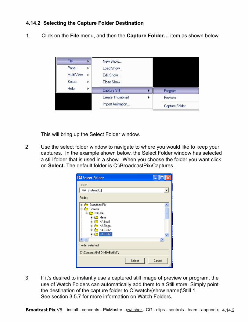
install - concepts - PixMaster - switcher - CG - clips - controls - team - appendix Broadcast Pix V8 4.14.2
4.14.2 Selecting the Capture Folder Destination
1. Click on the File menu, and then the Capture Folder… item as shown below
This will bring up the Select Folder window.
2. Use the select folder window to navigate to where you would like to keep your captures. In the example shown below, the Select Folder window has selected a still folder that is used in a show. When you choose the folder you want click on Select. The default folder is C:\BroadcastPix\Captures.
3. If it’s desired to instantly use a captured still image of preview or program, the use of Watch Folders can automatically add them to a Still store. Simply point the destination of the capture folder to C:\watch\(show name)\Still 1. See section 3.5.7 for more information on Watch Folders.
install - concepts - PixMaster - switcher - CG - clips - controls - team - appendix Broadcast Pix V8
Every Broadcast Pix Slate system includes a broadcast-quality character generator from Harris called Inscriber TitleMotion Pro. The CG has very extensive help menus. No attempt is made here to cover all of the capabilities of the application.
Instead, this section 5 of the Broadcast Pix manual provides a quick overview of how to create CG graphics, and then focuses on how to import them into the Broadcast Pix system, and how to control them on-air from the Broadcast Pix control panel.
TitleMotion Pro can create three main types of CG graphics:
1. Still images see section 5.2
2. Rolls/Crawls see section 5.3
3. 2D/3D Animations see section 5.4
5.1 CG Installation
The Broadcast Pix system ships with the Inscriber TitleMotion Pro software already installed. The Inscriber box packed with the system includes a copy of the CG software, and a purple application dongle. The dongle must be attached to the system to be able to open and use the application. The dongle attaches to any USB port on the back of the workstation. If the dongle is not attached when you attempt to open the application, you will get an error message that reads dongle error.
The included Inscriber CD may be installed on other systems, but they will only work when the dongle is moved to them. Additional dongles may be purchased as options.
If the optional CG Connect software is purchased, it too will come pre-installed on your system. To operate CG Connect a green dongle is provided, which needs to be plugged into another USB port.
On newer systems, both the TitleMotion Pro and CG Connect Dongles are installed internally at the factory.
5.1
Section 5: Inscriber Character Generator

install - concepts - PixMaster - switcher - CG - clips - controls - team - appendix Broadcast Pix V8
5.1.1 TitleMotion Pro Canvas
Before creating any graphics with Inscriber TitleMotion Pro, it may be helpful to understand the main window/canvas of the application. Below is a blank canvas with a brief overview of some main buttons, for further information refer to the Help drop down menu in TitleMotion Pro.
5.1.1
NOTE: It may be useful to turn on the Title Safe zone, which can be found under the View Tab on the bottom on the Inscriber canvas. This will act as a guide when creating graphics so your text does not get cut off on the edges of TV screens.
Canvas: Workspace in which you create CGs
Text / Graphic Plane: Select to activate a text or graphic layer. CTRL + Mouse Click on text or graphic will do the same.
Styles Palette: Shortcut to customizable styles for text/graphics Template Manager: Drop down
menu to access 200+ pre-designed or user-saved templates
Title Types: Select from Still, Roll, Crawl or Animation
Tool Palette: Select to create various text, logos, or custom graphics
Size & Attributes: Change type of font and its attributes. Color & Texture: Change text/graphic’s coloring/shading. Can be solid, gradient, transparent or textured. Styles: Save custom font and graphic styles for quick recalling. Logos: Where pictures, clip-art and other graphic elements are stored. Right-Click to add to library. Background: Add a full-page colored background or graphic. Default is transparent/none. News Edit: Where RTX Tags are applied for CG Connect.
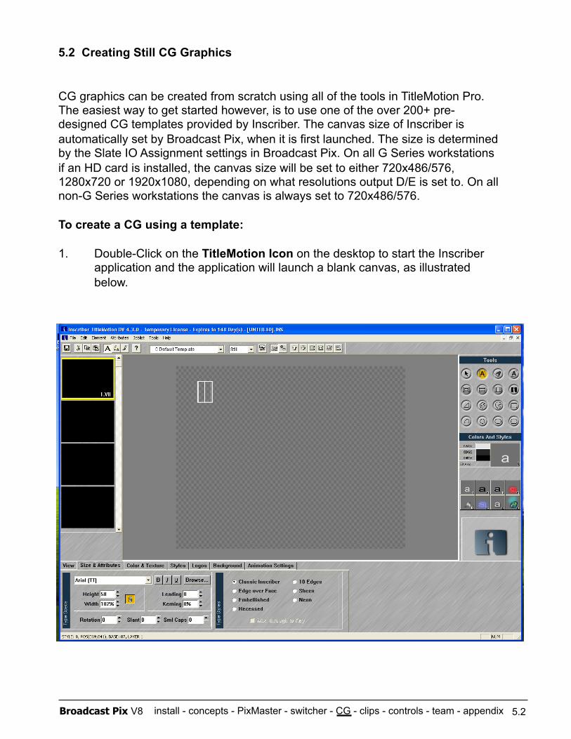
install - concepts - PixMaster - switcher - CG - clips - controls - team - appendix Broadcast Pix V8
5.2 Creating Still CG Graphics
CG graphics can be created from scratch using all of the tools in TitleMotion Pro. The easiest way to get started however, is to use one of the over 200+ pre- designed CG templates provided by Inscriber. The canvas size of Inscriber is automatically set by Broadcast Pix, when it is first launched. The size is determined by the Slate IO Assignment settings in Broadcast Pix. On all G Series workstations if an HD card is installed, the canvas size will be set to either 720x486/576, 1280x720 or 1920x1080, depending on what resolutions output D/E is set to. On all non-G Series workstations the canvas is always set to 720x486/576.
To create a CG using a template:
1. Double-Click on the TitleMotion Icon on the desktop to start the Inscriber application and the application will launch a blank canvas, as illustrated below.
5.2
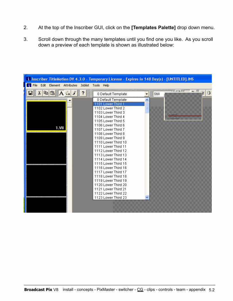
install - concepts - PixMaster - switcher - CG - clips - controls - team - appendix Broadcast Pix V8
2. At the top of the Inscriber GUI, click on the [Templates Palette] drop down menu.
3. Scroll down through the many templates until you find one you like. As you scroll down a preview of each template is shown as illustrated below:
5.2
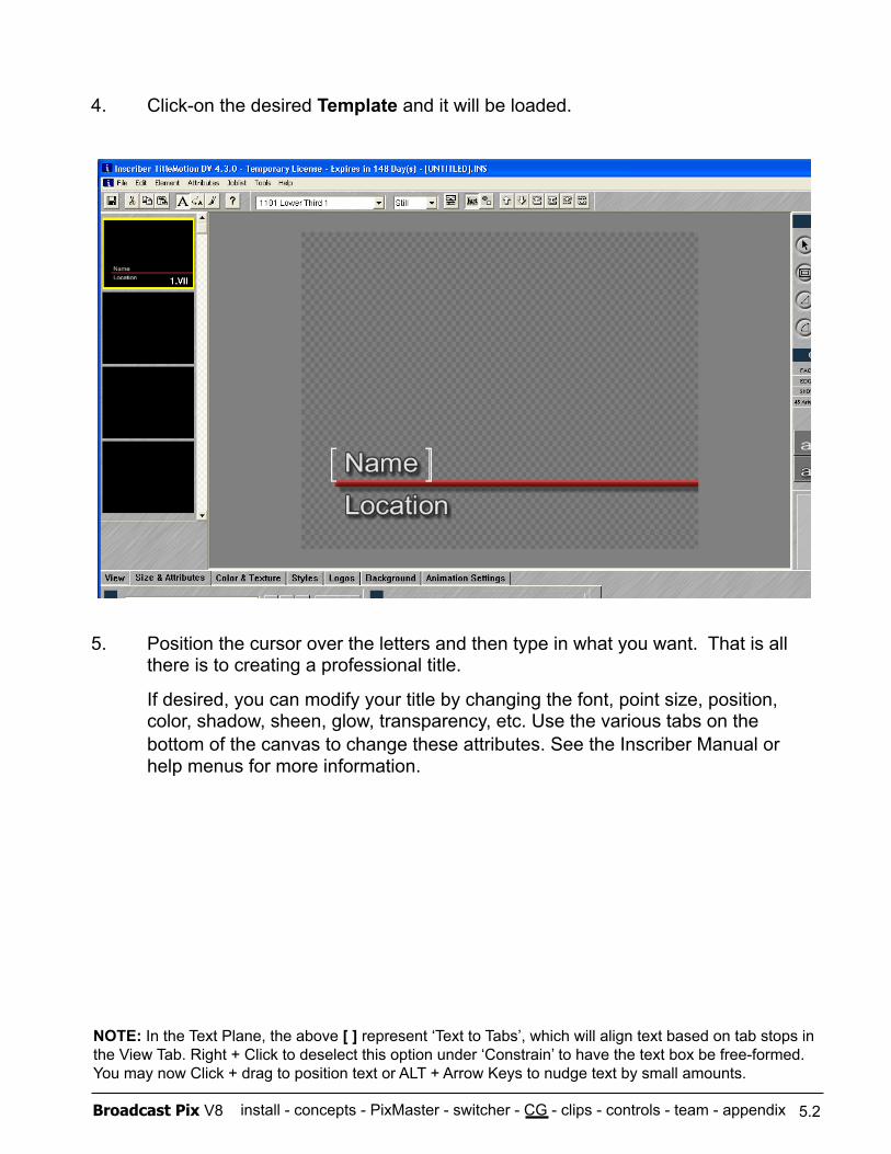
install - concepts - PixMaster - switcher - CG - clips - controls - team - appendix Broadcast Pix V8
4. Click-on the desired Template and it will be loaded.
5. Position the cursor over the letters and then type in what you want. That is all there is to creating a professional title.
If desired, you can modify your title by changing the font, point size, position, color, shadow, sheen, glow, transparency, etc. Use the various tabs on the bottom of the canvas to change these attributes. See the Inscriber Manual or help menus for more information.
5.2
NOTE: In the Text Plane, the above [ ] represent ‘Text to Tabs’, which will align text based on tab stops in the View Tab. Right + Click to deselect this option under ‘Constrain’ to have the text box be free-formed. You may now Click + drag to position text or ALT + Arrow Keys to nudge text by small amounts.
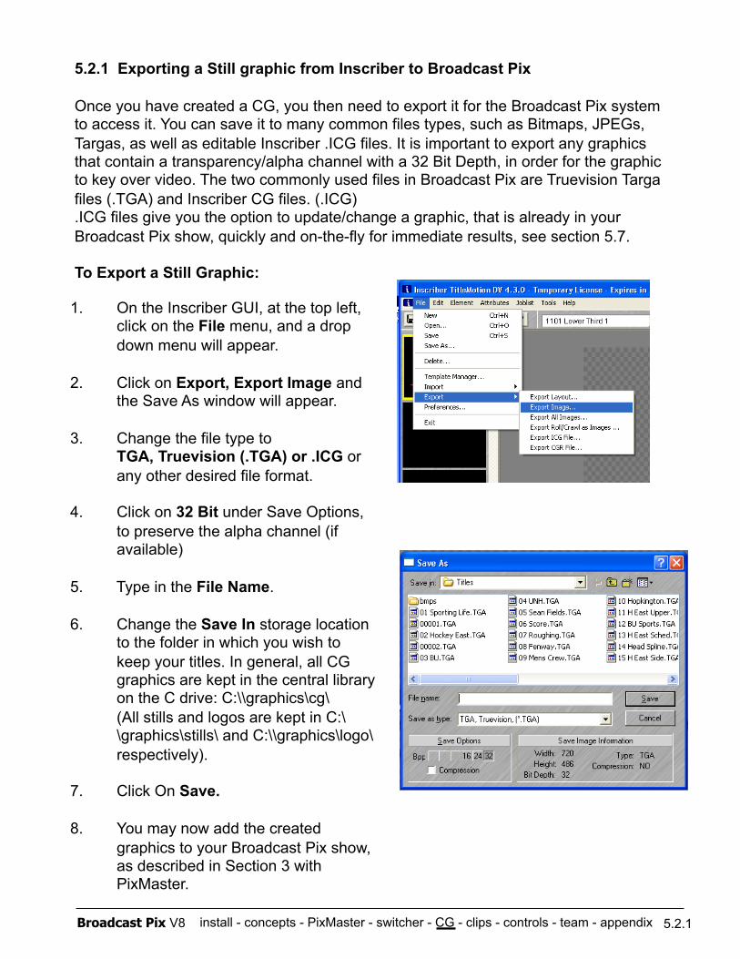
install - concepts - PixMaster - switcher - CG - clips - controls - team - appendix Broadcast Pix V8
5.2.1 Exporting a Still graphic from Inscriber to Broadcast Pix
Once you have created a CG, you then need to export it for the Broadcast Pix system to access it. You can save it to many common files types, such as Bitmaps, JPEGs, Targas, as well as editable Inscriber .ICG files. It is important to export any graphics that contain a transparency/alpha channel with a 32 Bit Depth, in order for the graphic to key over video. The two commonly used files in Broadcast Pix are Truevision Targa files (.TGA) and Inscriber CG files. (.ICG) .ICG files give you the option to update/change a graphic, that is already in your Broadcast Pix show, quickly and on-the-fly for immediate results, see section 5.7.
To Export a Still Graphic:
1. On the Inscriber GUI, at the top left, click on the File menu, and a drop down menu will appear.
2. Click on Export, Export Image and the Save As window will appear.
3. Change the file type to TGA, Truevision (.TGA) or .ICG or any other desired file format.
4. Click on 32 Bit under Save Options, to preserve the alpha channel (if available)
5. Type in the File Name.
6. Change the Save In storage location to the folder in which you wish to keep your titles. In general, all CG graphics are kept in the central library on the C drive: C:\\graphics\cg\
(All stills and logos are kept in C:\\graphics\stills\ and C:\\graphics\logo\ respectively).
7. Click On Save.
8. You may now add the created graphics to your Broadcast Pix show, as described in Section 3 with PixMaster.
5.2.1
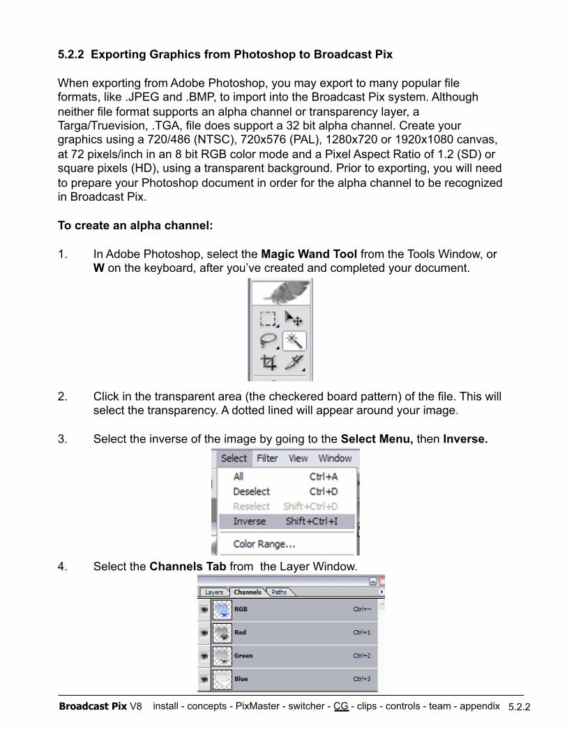
install - concepts - PixMaster - switcher - CG - clips - controls - team - appendix Broadcast Pix V8
5.2.2 Exporting Graphics from Photoshop to Broadcast Pix
When exporting from Adobe Photoshop, you may export to many popular file formats, like .JPEG and .BMP, to import into the Broadcast Pix system. Although neither file format supports an alpha channel or transparency layer, a Targa/Truevision, .TGA, file does support a 32 bit alpha channel. Create your graphics using a 720/486 (NTSC), 720x576 (PAL), 1280x720 or 1920x1080 canvas, at 72 pixels/inch in an 8 bit RGB color mode and a Pixel Aspect Ratio of 1.2 (SD) or square pixels (HD), using a transparent background. Prior to exporting, you will need to prepare your Photoshop document in order for the alpha channel to be recognized in Broadcast Pix.
To create an alpha channel:
1. In Adobe Photoshop, select the Magic Wand Tool from the Tools Window, or W on the keyboard, after you’ve created and completed your document.
2. Click in the transparent area (the checkered board pattern) of the file. This will select the transparency. A dotted lined will appear around your image.
3. Select the inverse of the image by going to the Select Menu, then Inverse.
4. Select the Channels Tab from the Layer Window.
5.2.2
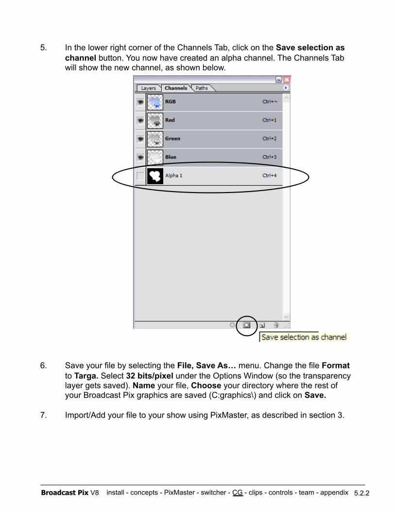
install - concepts - PixMaster - switcher - CG - clips - controls - team - appendix Broadcast Pix V8
5. In the lower right corner of the Channels Tab, click on the Save selection as channel button. You now have created an alpha channel. The Channels Tab will show the new channel, as shown below.
6. Save your file by selecting the File, Save As… menu. Change the file Format to Targa. Select 32 bits/pixel under the Options Window (so the transparency layer gets saved). Name your file, Choose your directory where the rest of your Broadcast Pix graphics are saved (C:graphics\) and click on Save.
7. Import/Add your file to your show using PixMaster, as described in section 3.
5.2.2
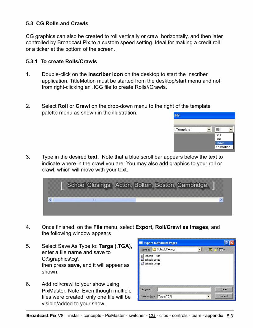
install - concepts - PixMaster - switcher - CG - clips - controls - team - appendix Broadcast Pix V8
5.3 CG Rolls and Crawls
CG graphics can also be created to roll vertically or crawl horizontally, and then later controlled by Broadcast Pix to a custom speed setting. Ideal for making a credit roll or a ticker at the bottom of the screen.
5.3.1 To create Rolls/Crawls
1. Double-click on the Inscriber icon on the desktop to start the Inscriber application. TitleMotion must be started from the desktop/start menu and not from right-clicking an .ICG file to create Rolls//Crawls.
2. Select Roll or Crawl on the drop-down menu to the right of the template palette menu as shown in the illustration.
3. Type in the desired text. Note that a blue scroll bar appears below the text to indicate where in the crawl you are. You may also add graphics to your roll or crawl, which will move with your text.
4. Once finished, on the File menu, select Export, Roll/Crawl as Images, and the following window appears
5. Select Save As Type to: Targa (.TGA), enter a file name and save to C:\\graphics\cg\ then press save, and it will appear as shown.
6. Add roll/crawl to your show using PixMaster. Note: Even though multiple files were created, only one file will be visible/added to your show.
5.3
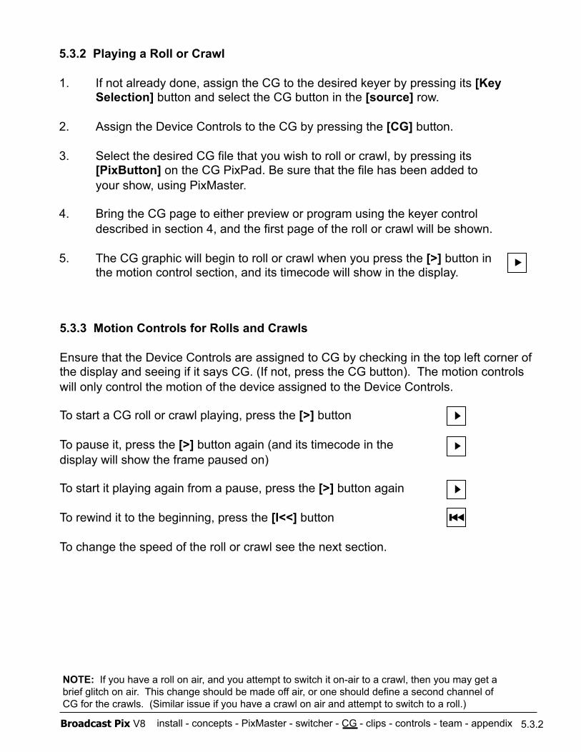
install - concepts - PixMaster - switcher - CG - clips - controls - team - appendix Broadcast Pix V8
5.3.2 Playing a Roll or Crawl
1. If not already done, assign the CG to the desired keyer by pressing its [Key Selection] button and select the CG button in the [source] row.
2. Assign the Device Controls to the CG by pressing the [CG] button.
3. Select the desired CG file that you wish to roll or crawl, by pressing its [PixButton] on the CG PixPad. Be sure that the file has been added to your show, using PixMaster.
4. Bring the CG page to either preview or program using the keyer control described in section 4, and the first page of the roll or crawl will be shown.
5. The CG graphic will begin to roll or crawl when you press the [>] button in the motion control section, and its timecode will show in the display.
5.3.3 Motion Controls for Rolls and Crawls
Ensure that the Device Controls are assigned to CG by checking in the top left corner of the display and seeing if it says CG. (If not, press the CG button). The motion controls will only control the motion of the device assigned to the Device Controls.
To start a CG roll or crawl playing, press the [>] button
To pause it, press the [>] button again (and its timecode in the display will show the frame paused on)
To start it playing again from a pause, press the [>] button again
To rewind it to the beginning, press the [I<<] button
To change the speed of the roll or crawl see the next section.
5.3.2
NOTE: If you have a roll on air, and you attempt to switch it on-air to a crawl, then you may get a brief glitch on air. This change should be made off air, or one should define a second channel of CG for the crawls. (Similar issue if you have a crawl on air and attempt to switch to a roll.)

install - concepts - PixMaster - switcher - CG - clips - controls - team - appendix Broadcast Pix V8
5.3.4 Modifiers for Rolls and Crawls
Modifiers may be applied to rolls and crawls. These include changing a roll to a crawl, adding a blank page at the beginning and/or end, setting it to loop, setting it to auto-start when taken to air, changing the read direction, changing the aspect ratio and changing its speed.
To modify a roll or a crawl:
1. Press the [CG] button to bring up the top page of CG controls on the PixPad, if they are not already up.
2. Press the [Controls] PixButton, which will bring up the following PixPad of Modifiers:
CG Controls PixPad
5.3.4
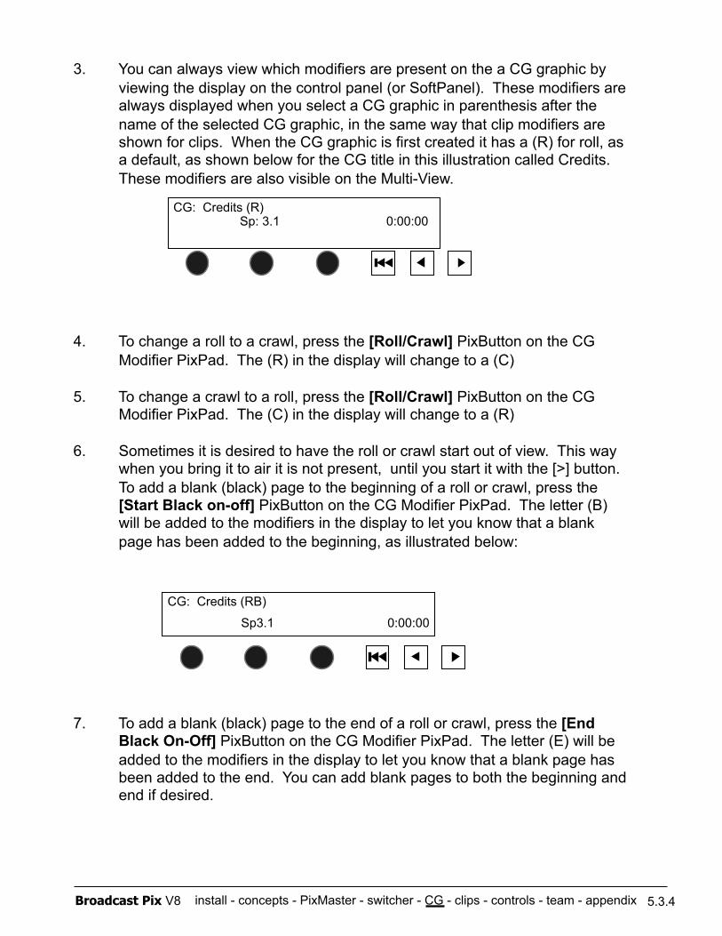
install - concepts - PixMaster - switcher - CG - clips - controls - team - appendix Broadcast Pix V8
3. You can always view which modifiers are present on the a CG graphic by viewing the display on the control panel (or SoftPanel). These modifiers are always displayed when you select a CG graphic in parenthesis after the name of the selected CG graphic, in the same way that clip modifiers are shown for clips. When the CG graphic is first created it has a (R) for roll, as a default, as shown below for the CG title in this illustration called Credits. These modifiers are also visible on the Multi-View.
4. To change a roll to a crawl, press the [Roll/Crawl] PixButton on the CG Modifier PixPad. The (R) in the display will change to a (C)
5. To change a crawl to a roll, press the [Roll/Crawl] PixButton on the CG Modifier PixPad. The (C) in the display will change to a (R)
6. Sometimes it is desired to have the roll or crawl start out of view. This way when you bring it to air it is not present, until you start it with the [>] button. To add a blank (black) page to the beginning of a roll or crawl, press the [Start Black on-off] PixButton on the CG Modifier PixPad. The letter (B) will be added to the modifiers in the display to let you know that a blank page has been added to the beginning, as illustrated below:
7. To add a blank (black) page to the end of a roll or crawl, press the [End Black On-Off] PixButton on the CG Modifier PixPad. The letter (E) will be added to the modifiers in the display to let you know that a blank page has been added to the end. You can add blank pages to both the beginning and end if desired.
CG: Credits (R) Sp: 3.1 0:00:00
CG: Credits (RB)
Sp3.1 0:00:00
5.3.4
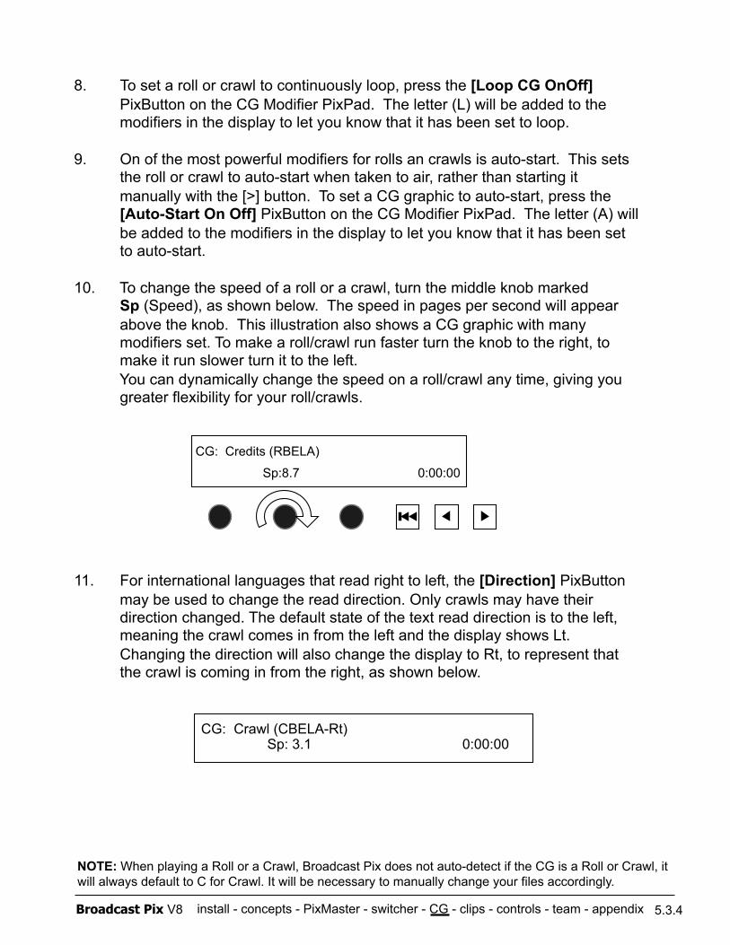
install - concepts - PixMaster - switcher - CG - clips - controls - team - appendix Broadcast Pix V8
8. To set a roll or crawl to continuously loop, press the [Loop CG OnOff] PixButton on the CG Modifier PixPad. The letter (L) will be added to the modifiers in the display to let you know that it has been set to loop.
9. On of the most powerful modifiers for rolls an crawls is auto-start. This sets the roll or crawl to auto-start when taken to air, rather than starting it manually with the [>] button. To set a CG graphic to auto-start, press the [Auto-Start On Off] PixButton on the CG Modifier PixPad. The letter (A) will be added to the modifiers in the display to let you know that it has been set to auto-start.
10. To change the speed of a roll or a crawl, turn the middle knob marked Sp (Speed), as shown below. The speed in pages per second will appear above the knob. This illustration also shows a CG graphic with many modifiers set. To make a roll/crawl run faster turn the knob to the right, to make it run slower turn it to the left. You can dynamically change the speed on a roll/crawl any time, giving you greater flexibility for your roll/crawls.
11. For international languages that read right to left, the [Direction] PixButton may be used to change the read direction. Only crawls may have their direction changed. The default state of the text read direction is to the left, meaning the crawl comes in from the left and the display shows Lt. Changing the direction will also change the display to Rt, to represent that the crawl is coming in from the right, as shown below.
CG: Credits (RBELA)
Sp:8.7 0:00:00
5.3.4
NOTE: When playing a Roll or a Crawl, Broadcast Pix does not auto-detect if the CG is a Roll or Crawl, it will always default to C for Crawl. It will be necessary to manually change your files accordingly.
CG: Crawl (CBELA-Rt) Sp: 3.1 0:00:00
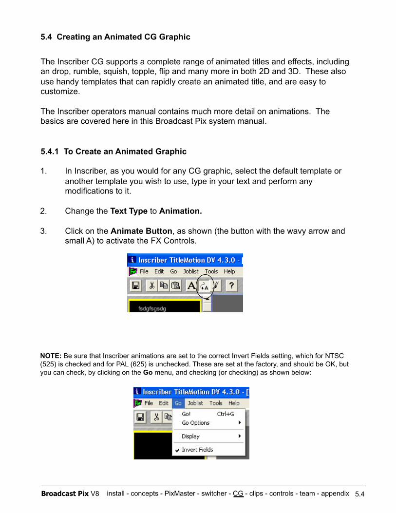
install - concepts - PixMaster - switcher - CG - clips - controls - team - appendix Broadcast Pix V8
5.4 Creating an Animated CG Graphic
The Inscriber CG supports a complete range of animated titles and effects, including an drop, rumble, squish, topple, flip and many more in both 2D and 3D. These also use handy templates that can rapidly create an animated title, and are easy to customize.
The Inscriber operators manual contains much more detail on animations. The basics are covered here in this Broadcast Pix system manual.
5.4.1 To Create an Animated Graphic
1. In Inscriber, as you would for any CG graphic, select the default template or another template you wish to use, type in your text and perform any modifications to it.
2. Change the Text Type to Animation.
3. Click on the Animate Button, as shown (the button with the wavy arrow and small A) to activate the FX Controls.
NOTE: Be sure that Inscriber animations are set to the correct Invert Fields setting, which for NTSC (525) is checked and for PAL (625) is unchecked. These are set at the factory, and should be OK, but you can check, by clicking on the Go menu, and checking (or checking) as shown below:
5.4

install - concepts - PixMaster - switcher - CG - clips - controls - team - appendix Broadcast Pix V8
4. Select an animation template from those shown at the bottom, For example, you might select tip and scale as shown below.
5. You can sample this animation by pressing the green [>] button. If you like it, click on Apply as shown above.
6. If desired, you can move the animation movement points for the chosen animation by clicking on them in the large window showing your text, and dragging them to another location. You can also add key frames and adjust the timing of animations in the various controls tabs on the bottom of the screen.
7. You can preview the animation at any time, either using a wire-frame view, which is quicker but does not provide any graphical information, or a full-quality view, which is slower than real-time but provides and accurate representation of the file animation, by selecting the preview buttons on the canvas.
8. Save the animation by clicking on File, and then a drop down menu appears and click on Import/Export, and then Export All Frames, as shown below:
5.4.1
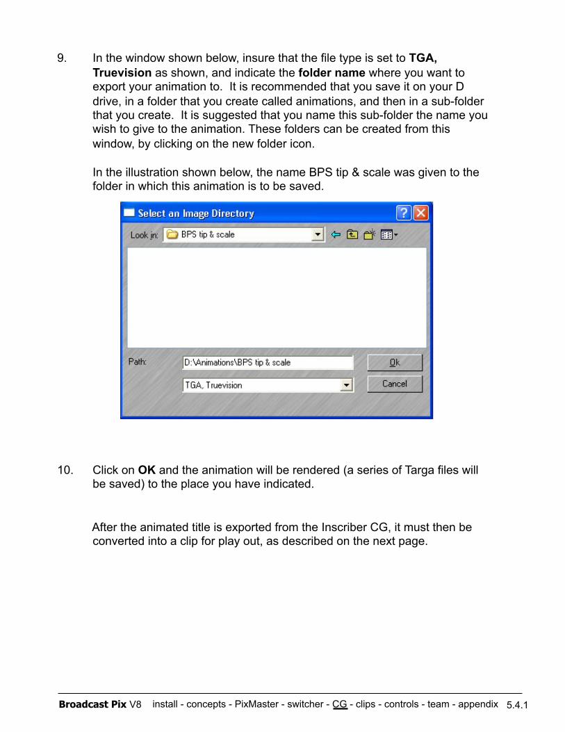
install - concepts - PixMaster - switcher - CG - clips - controls - team - appendix Broadcast Pix V8
9. In the window shown below, insure that the file type is set to TGA, Truevision as shown, and indicate the folder name where you want to export your animation to. It is recommended that you save it on your D drive, in a folder that you create called animations, and then in a sub-folder that you create. It is suggested that you name this sub-folder the name you wish to give to the animation. These folders can be created from this window, by clicking on the new folder icon.
In the illustration shown below, the name BPS tip & scale was given to the folder in which this animation is to be saved.
10. Click on OK and the animation will be rendered (a series of Targa files will be saved) to the place you have indicated.
After the animated title is exported from the Inscriber CG, it must then be converted into a clip for play out, as described on the next page.
5.4.1
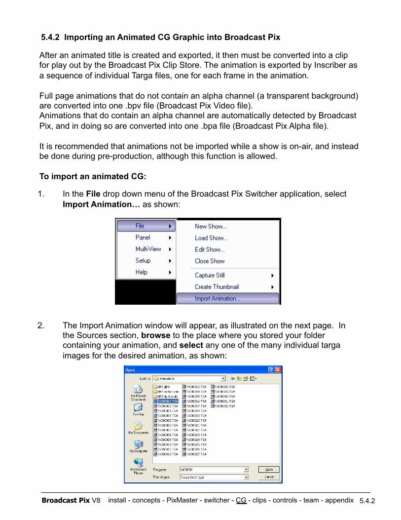
install - concepts - PixMaster - switcher - CG - clips - controls - team - appendix Broadcast Pix V8
After an animated title is created and exported, it then must be converted into a clip for play out by the Broadcast Pix Clip Store. The animation is exported by Inscriber as a sequence of individual Targa files, one for each frame in the animation.
Full page animations that do not contain an alpha channel (a transparent background) are converted into one .bpv file (Broadcast Pix Video file). Animations that do contain an alpha channel are automatically detected by Broadcast Pix, and in doing so are converted into one .bpa file (Broadcast Pix Alpha file).
It is recommended that animations not be imported while a show is on-air, and instead be done during pre-production, although this function is allowed.
To import an animated CG:
5.4.2 Importing an Animated CG Graphic into Broadcast Pix
1. In the File drop down menu of the Broadcast Pix Switcher application, select Import Animation… as shown:
2. The Import Animation window will appear, as illustrated on the next page. In the Sources section, browse to the place where you stored your folder containing your animation, and select any one of the many individual targa images for the desired animation, as shown:
5.4.2
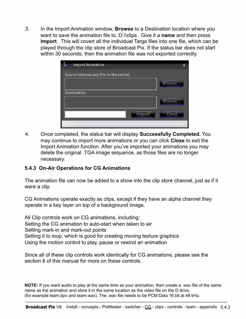
install - concepts - PixMaster - switcher - CG - clips - controls - team - appendix Broadcast Pix V8
3. In the Import Animation window, Browse to a Destination location where you want to save the animation file to, D:\\clips . Give it a name and then press Import. This will covert all the individual Targa files into one file, which can be played through the clip store of Broadcast Pix. If the status bar does not start within 30 seconds, then the animation file was not exported correctly.
4. Once completed, the status bar will display Successfully Completed. You may continue to import more animations or you can click Close to exit the Import Animation function. After you’ve imported your animations you may delete the original .TGA image sequence, as those files are no longer necessary.
5.4.3 On-Air Operations for CG Animations
The animation file can now be added to a show into the clip store channel, just as if it were a clip.
CG Animations operate exactly as clips, except if they have an alpha channel they operate in a key layer on top of a background image.
All Clip controls work on CG animations, including: Setting the CG animation to auto-start when taken to air Setting mark-in and mark-out points Setting it to loop, which is good for creating moving texture graphics Using the motion control to play, pause or rewind an animation
Since all of these clip controls work identically for CG animations, please see the section 6 of this manual for more on these controls.
NOTE: If you want audio to play at the same time as your animation, then create a .wav file of the same name as the animation and store it in the same location as the video file on the D drive, (for example team.bpv and team.wav). The .wav file needs to be PCM Data 16 bit at 48 kHz.
5.4.3
install - concepts - PixMaster - switcher - CG - clips - controls - team - appendix Broadcast Pix V8
5.4.4 Creating Animations in 3rd party Applications.
Inscriber makes great animations, but you can use many popular animation applications including Digital Juice, Art Beats, Adobe After Effects, Apple Motion and others to make animations for the Broadcast Pix system. In general, any animation system that can export a sequence of frames of images will work, as these frames can be brought into the Broadcast Pix systems and converted into .bpv or .bpa file, as previously described.
5.4.4
For example, for creating an animation in Digital Juice:
1. Select the Jump Back or other Digital Juice graphic you want.
2. Set your Digital Juice controls to output a sequence of files.
3. Set the file type to be Targa*, with the right number of frames per second (depending on whether you are in NTSC/525 or PAL/625.)
4. Run Digital Juice to create the animation sequence.
5. Import the animation into Broadcast Pix just as if it were coming from Inscriber, see section 5.4.2.
• Other formats can also be used. You do not have to use Targa files, as the system will also import a series of .bmp, .jpg or .png files.
NOTE: If you are creating animations with alpha channels make sure to save files as 32 Bit Targa files to preserve the transparency layer.
All image sequences need to end with a number starting with “0” in order for the Import Animation function of Broadcast Pix to work properly. (i.e. Animation000000 or Animation2_000000)
If the status bar in the Import Animation function does not move after 30 seconds of importing, then your files/file names have not been exported correctly.
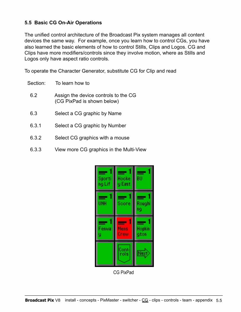
install - concepts - PixMaster - switcher - CG - clips - controls - team - appendix Broadcast Pix V8
5.5 Basic CG On-Air Operations
The unified control architecture of the Broadcast Pix system manages all content devices the same way. For example, once you learn how to control CGs, you have also learned the basic elements of how to control Stills, Clips and Logos. CG and Clips have more modifiers/controls since they involve motion, where as Stills and Logos only have aspect ratio controls.
To operate the Character Generator, substitute CG for Clip and read
Section: To learn how to
6.2 Assign the device controls to the CG (CG PixPad is shown below)
6.3 Select a CG graphic by Name
6.3.1 Select a CG graphic by Number
6.3.2 Select CG graphics with a mouse
6.3.3 View more CG graphics in the Multi-View
CG PixPad
5.5
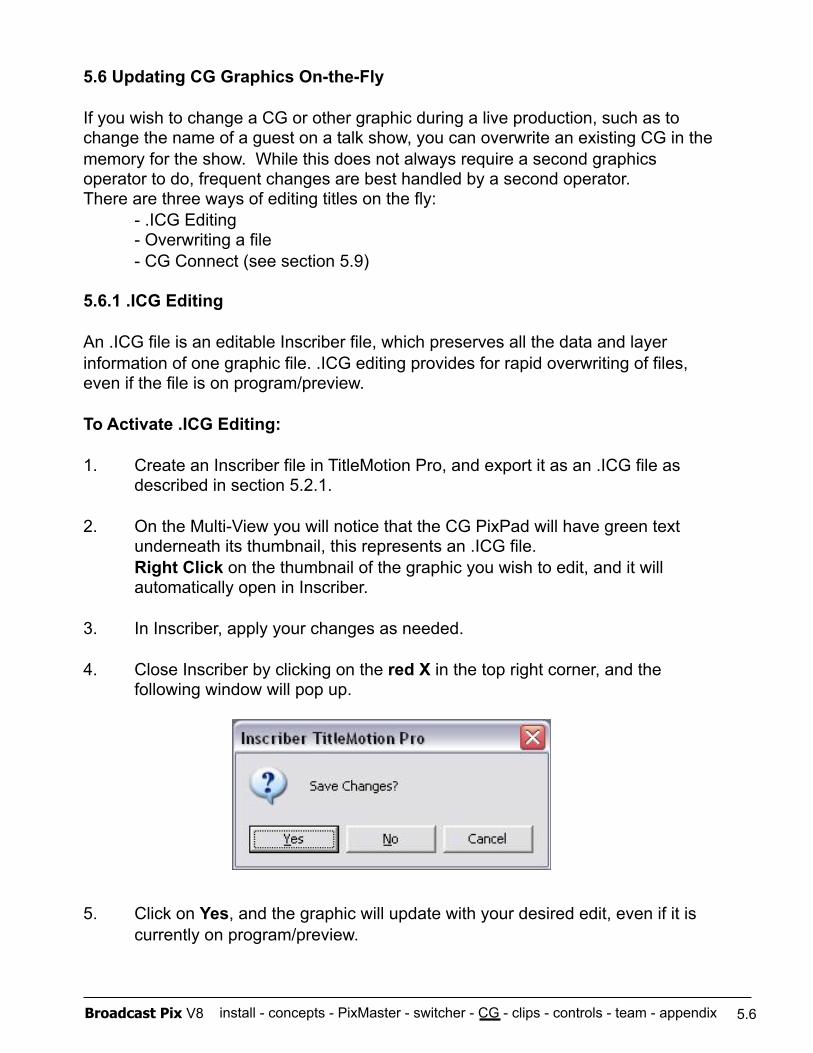
install - concepts - PixMaster - switcher - CG - clips - controls - team - appendix Broadcast Pix V8
5.6 Updating CG Graphics On-the-Fly
If you wish to change a CG or other graphic during a live production, such as to change the name of a guest on a talk show, you can overwrite an existing CG in the memory for the show. While this does not always require a second graphics operator to do, frequent changes are best handled by a second operator. There are three ways of editing titles on the fly:
- .ICG Editing - Overwriting a file - CG Connect (see section 5.9)
5.6.1 .ICG Editing
An .ICG file is an editable Inscriber file, which preserves all the data and layer information of one graphic file. .ICG editing provides for rapid overwriting of files, even if the file is on program/preview.
To Activate .ICG Editing:
1. Create an Inscriber file in TitleMotion Pro, and export it as an .ICG file as described in section 5.2.1.
2. On the Multi-View you will notice that the CG PixPad will have green text underneath its thumbnail, this represents an .ICG file. Right Click on the thumbnail of the graphic you wish to edit, and it will automatically open in Inscriber.
3. In Inscriber, apply your changes as needed.
4. Close Inscriber by clicking on the red X in the top right corner, and the following window will pop up.
5. Click on Yes, and the graphic will update with your desired edit, even if it is currently on program/preview.
5.6
install - concepts - PixMaster - switcher - CG - clips - controls - team - appendix Broadcast Pix V8
5.6.2 Overwriting a File
Another way to update a file that is currently in your show is to simply overwrite the file using standard Microsoft Windows. This may be desired if you have the Broadcast Pix workstation plugged into a separate local network, where files can be shared and saved. The use of Watch Folders can assist in automatically replacing/overwriting graphic files, see section 3.5.7 for more information.
To Overwrite a File:
1. Create a CG in either Inscriber or any other graphics application.
2. Export the graphic with the same file name and file extension as the one you wish to replace, i.e. .TGA, .JPEG, .BMP
3. Save the file in the same location as the current version. C:\\graphics\cg And click on Yes when asked to Replace/Overwrite the existing file.
4. The file will automatically update, glitch-free, on program/preview.
5.7 Dual CG
The Broadcast Pix Switcher software enables a second channel of CG to be used in a show. This enables two CG graphics to be displayed on-air at once, one in its own keyers, taking up 2 Keyers.
To have two channels of CG in a show, in PixMaster Show Editor simply dedicate two sources to CGs. They may have different content of CG titles assigned, or each access the same content.
Both CG channels may have still images, or one can play a roll or a crawl while the other is holding a still titles or both can be playing a roll/crawl.
To transition between two CG channels, simply deselect the [Bgr] button in the transitions controls and select the Key channels you wish to effect.
5.6.1
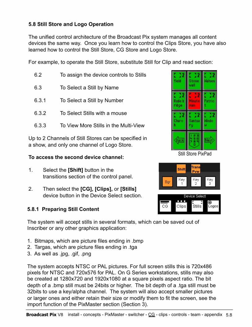
install - concepts - PixMaster - switcher - CG - clips - controls - team - appendix Broadcast Pix V8
5.8 Still Store and Logo Operation
The unified control architecture of the Broadcast Pix system manages all content devices the same way. Once you learn how to control the Clips Store, you have also learned how to control the Still Store, CG Store and Logo Store.
For example, to operate the Still Store, substitute Still for Clip and read section:
6.2 To assign the device controls to Stills
6.3 To Select a Still by Name
6.3.1 To Select a Still by Number
6.3.2 To Select Stills with a mouse
6.3.3 To View More Stills in the Multi-View
Up to 2 Channels of Still Stores can be specified in a show, and only one channel of Logo Store.
To access the second device channel:
1. Select the [Shift] button in the transitions section of the control panel.
2. Then select the [CG], [Clips], or [Stills] device button in the Device Select section.
5.8.1 Preparing Still Content
The system will accept stills in several formats, which can be saved out of Inscriber or any other graphics application:
1. Bitmaps, which are picture files ending in .bmp 2. Targas, which are picture files ending in .tga 3. As well as .jpg, .gif, .png
The system accepts NTSC or PAL pictures. For full screen stills this is 720x486 pixels for NTSC and 720x576 for PAL. On G Series workstations, stills may also be created at 1280x720 and 1920x1080 at a square pixels aspect ratio. The bit depth of a .bmp still must be 24bits or higher. The bit depth of a .tga still must be 32bits to use a key/alpha channel. The system will also accept smaller pictures or larger ones and either retain their size or modify them to fit the screen, see the import function of the PixMaster section (Section 3).
5.8
Still Store PixPad
Trans Pvw Shift
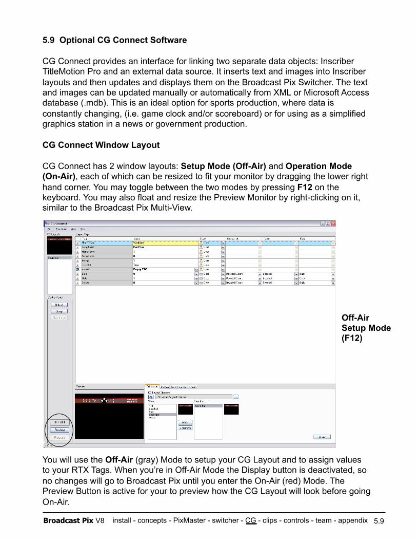
install - concepts - PixMaster - switcher - CG - clips - controls - team - appendix Broadcast Pix V8
5.9 Optional CG Connect Software
CG Connect provides an interface for linking two separate data objects: Inscriber TitleMotion Pro and an external data source. It inserts text and images into Inscriber layouts and then updates and displays them on the Broadcast Pix Switcher. The text and images can be updated manually or automatically from XML or Microsoft Access database (.mdb). This is an ideal option for sports production, where data is constantly changing, (i.e. game clock and/or scoreboard) or for using as a simplified graphics station in a news or government production.
CG Connect Window Layout
CG Connect has 2 window layouts: Setup Mode (Off-Air) and Operation Mode (On-Air), each of which can be resized to fit your monitor by dragging the lower right hand corner. You may toggle between the two modes by pressing F12 on the keyboard. You may also float and resize the Preview Monitor by right-clicking on it, similar to the Broadcast Pix Multi-View.
You will use the Off-Air (gray) Mode to setup your CG Layout and to assign values to your RTX Tags. When you’re in Off-Air Mode the Display button is deactivated, so no changes will go to Broadcast Pix until you enter the On-Air (red) Mode. The Preview Button is active for your to preview how the CG Layout will look before going On-Air.
5.9
Off-Air Setup Mode (F12)
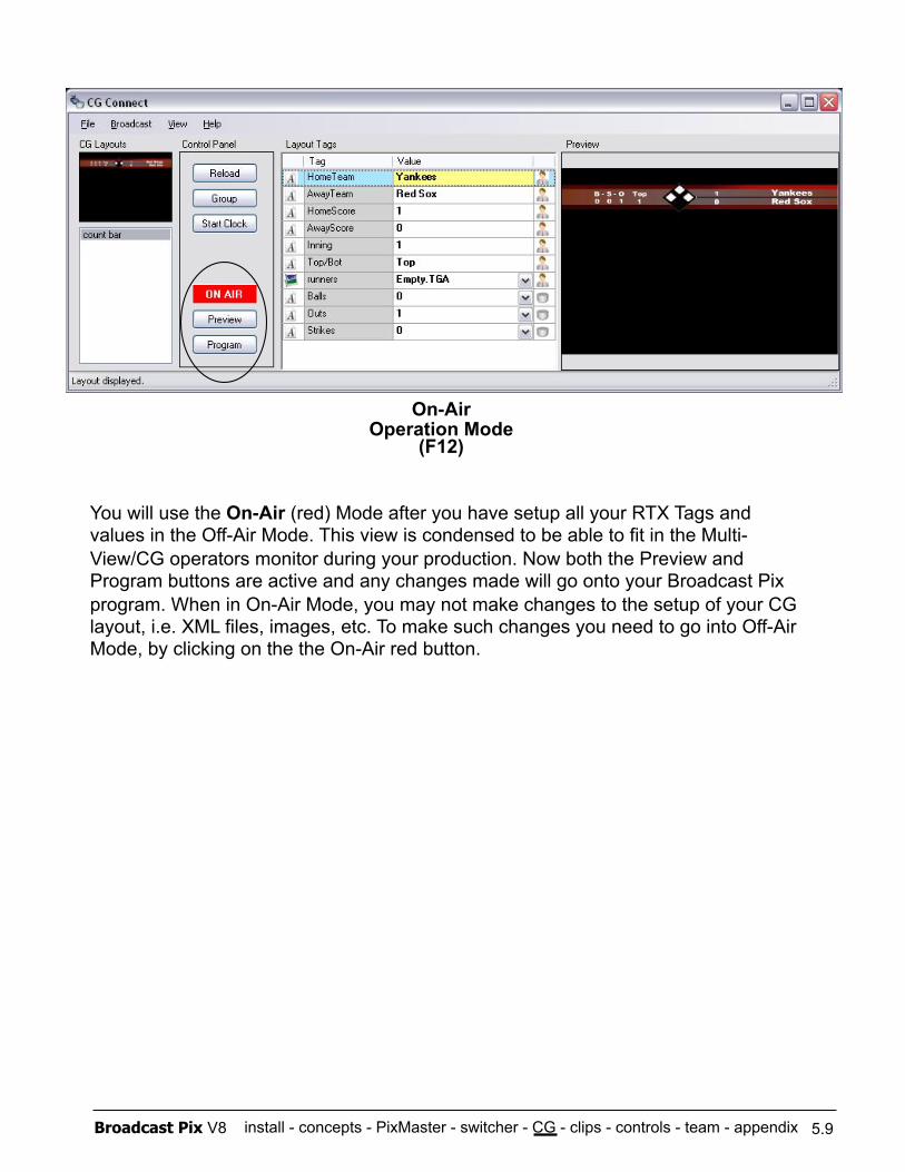
install - concepts - PixMaster - switcher - CG - clips - controls - team - appendix Broadcast Pix V8
You will use the On-Air (red) Mode after you have setup all your RTX Tags and values in the Off-Air Mode. This view is condensed to be able to fit in the Multi- View/CG operators monitor during your production. Now both the Preview and Program buttons are active and any changes made will go onto your Broadcast Pix program. When in On-Air Mode, you may not make changes to the setup of your CG layout, i.e. XML files, images, etc. To make such changes you need to go into Off-Air Mode, by clicking on the the On-Air red button.
5.9
On-Air Operation Mode
(F12)
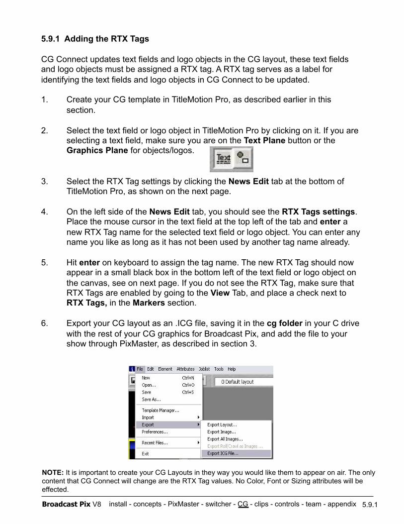
install - concepts - PixMaster - switcher - CG - clips - controls - team - appendix Broadcast Pix V8
5.9.1 Adding the RTX Tags
CG Connect updates text fields and logo objects in the CG layout, these text fields and logo objects must be assigned a RTX tag. A RTX tag serves as a label for identifying the text fields and logo objects in CG Connect to be updated.
1. Create your CG template in TitleMotion Pro, as described earlier in this section.
2. Select the text field or logo object in TitleMotion Pro by clicking on it. If you are selecting a text field, make sure you are on the Text Plane button or the Graphics Plane for objects/logos.
3. Select the RTX Tag settings by clicking the News Edit tab at the bottom of TitleMotion Pro, as shown on the next page.
4. On the left side of the News Edit tab, you should see the RTX Tags settings. Place the mouse cursor in the text field at the top left of the tab and enter a new RTX Tag name for the selected text field or logo object. You can enter any name you like as long as it has not been used by another tag name already.
5. Hit enter on keyboard to assign the tag name. The new RTX Tag should now appear in a small black box in the bottom left of the text field or logo object on the canvas, see on next page. If you do not see the RTX Tag, make sure that RTX Tags are enabled by going to the View Tab, and place a check next to RTX Tags, in the Markers section.
6. Export your CG layout as an .ICG file, saving it in the cg folder in your C drive with the rest of your CG graphics for Broadcast Pix, and add the file to your show through PixMaster, as described in section 3.
5.9.1
NOTE: It is important to create your CG Layouts in they way you would like them to appear on air. The only content that CG Connect will change are the RTX Tag values. No Color, Font or Sizing attributes will be effected.
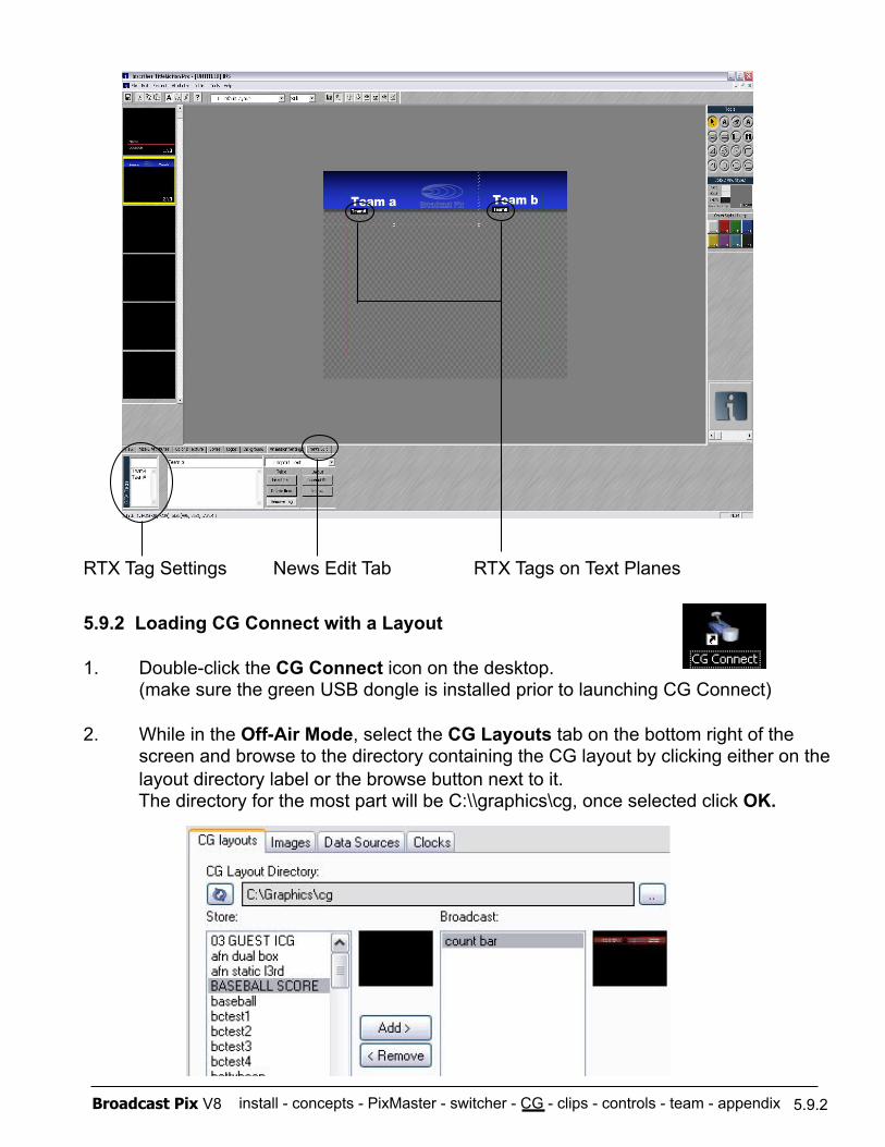
install - concepts - PixMaster - switcher - CG - clips - controls - team - appendix Broadcast Pix V8
5.9.2 Loading CG Connect with a Layout
1. Double-click the CG Connect icon on the desktop. (make sure the green USB dongle is installed prior to launching CG Connect)
2. While in the Off-Air Mode, select the CG Layouts tab on the bottom right of the screen and browse to the directory containing the CG layout by clicking either on the layout directory label or the browse button next to it. The directory for the most part will be C:\\graphics\cg, once selected click OK.
5.9.2
RTX Tag Settings News Edit Tab RTX Tags on Text Planes
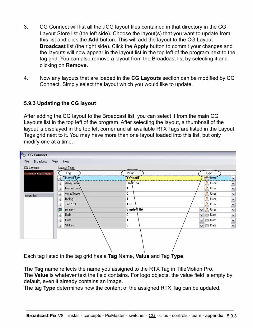
install - concepts - PixMaster - switcher - CG - clips - controls - team - appendix Broadcast Pix V8
3. CG Connect will list all the .ICG layout files contained in that directory in the CG Layout Store list (the left side). Choose the layout(s) that you want to update from this list and click the Add button. This will add the layout to the CG Layout Broadcast list (the right side). Click the Apply button to commit your changes and the layouts will now appear in the layout list in the top left of the program next to the tag grid. You can also remove a layout from the Broadcast list by selecting it and clicking on Remove.
4. Now any layouts that are loaded in the CG Layouts section can be modified by CG Connect. Simply select the layout which you would like to update.
5.9.3 Updating the CG layout
After adding the CG layout to the Broadcast list, you can select it from the main CG Layouts list in the top left of the program. After selecting the layout, a thumbnail of the layout is displayed in the top left corner and all available RTX Tags are listed in the Layout Tags grid next to it. You may have more than one layout loaded into this list, but only modify one at a time.
Each tag listed in the tag grid has a Tag Name, Value and Tag Type.
The Tag name reflects the name you assigned to the RTX Tag in TitleMotion Pro. The Value is whatever text the field contains. For logo objects, the value field is empty by default, even it already contains an image. The tag Type determines how the content of the assigned RTX Tag can be updated.
5.9.3
install - concepts - PixMaster - switcher - CG - clips - controls - team - appendix Broadcast Pix V8
The following 3 Tag Types are available:
User:
Allows you to manually enter text into a text field or select a list of images from a drop down list on the CG layout. This tag type is set by default for tags referencing a text field on the CG layout. After selecting this tag type, click on the value field in the grid and enter the new text you want to display. Hit Enter on keyboard to apply the new text.
Data:
Allows you to connect the tag to a data source/XML file. This tag type can be assigned to either a text field or a logo object. CG Connect will detect automatically which it is and use the data from the data source to either replace the text in the case of a text field, or to reference an image in the case of a logo object. This image must have been added to the broadcast image list first. The reference to this image is done by reading the filename for image from the data source. So, if the data source contains a value “Logo.jpg”, CG Connect will look for an image with this name in the images added to the Images broadcast list.
Clocks:
Allows you to display a clock, like the internal PC Clock. CG Connect will automatically update when the PC Clock changes. You may change the settings in the Clocks tab to display and update by the hour, minute or second as well as change the formatting.
5.9.4 Adding a Data Source with XML Files
CG Connect allows you to use Extensible Markup Language (XML) files as data sources to automatically update your RTX Tags in your CG layout. These XML files can be created by an external source, from a scoreboard for example, or created manually through in the internal Data Editor function.
1. Select the Data Sources tab, as shown on the next page.
2. Click on the New button to add a new data source and give it a name. Select OK. Or you may select from the drop down menu from the active data sources.
3. Click on the Source label or the browse button next to it to choose the XML file you want to use. The XML file will be loaded and tables found in the XML file are listed in the Tables list.
5.9.4
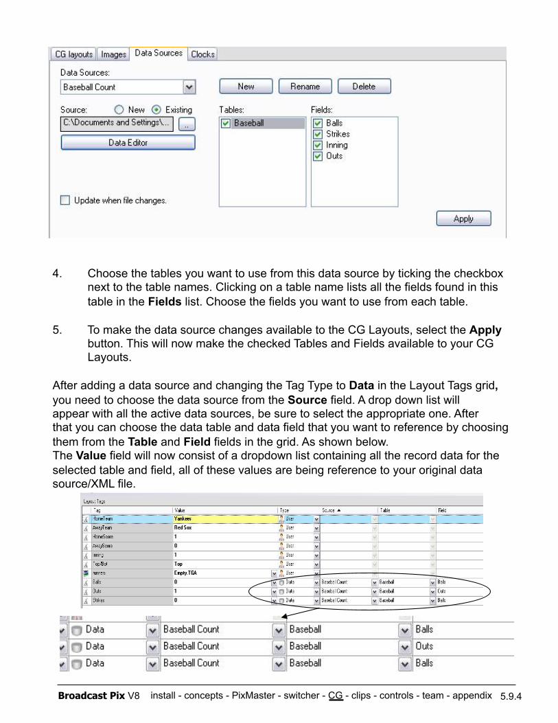
install - concepts - PixMaster - switcher - CG - clips - controls - team - appendix Broadcast Pix V8
4. Choose the tables you want to use from this data source by ticking the checkbox next to the table names. Clicking on a table name lists all the fields found in this table in the Fields list. Choose the fields you want to use from each table.
5. To make the data source changes available to the CG Layouts, select the Apply button. This will now make the checked Tables and Fields available to your CG Layouts.
After adding a data source and changing the Tag Type to Data in the Layout Tags grid, you need to choose the data source from the Source field. A drop down list will appear with all the active data sources, be sure to select the appropriate one. After that you can choose the data table and data field that you want to reference by choosing them from the Table and Field fields in the grid. As shown below. The Value field will now consist of a dropdown list containing all the record data for the selected table and field, all of these values are being reference to your original data source/XML file.
5.9.4
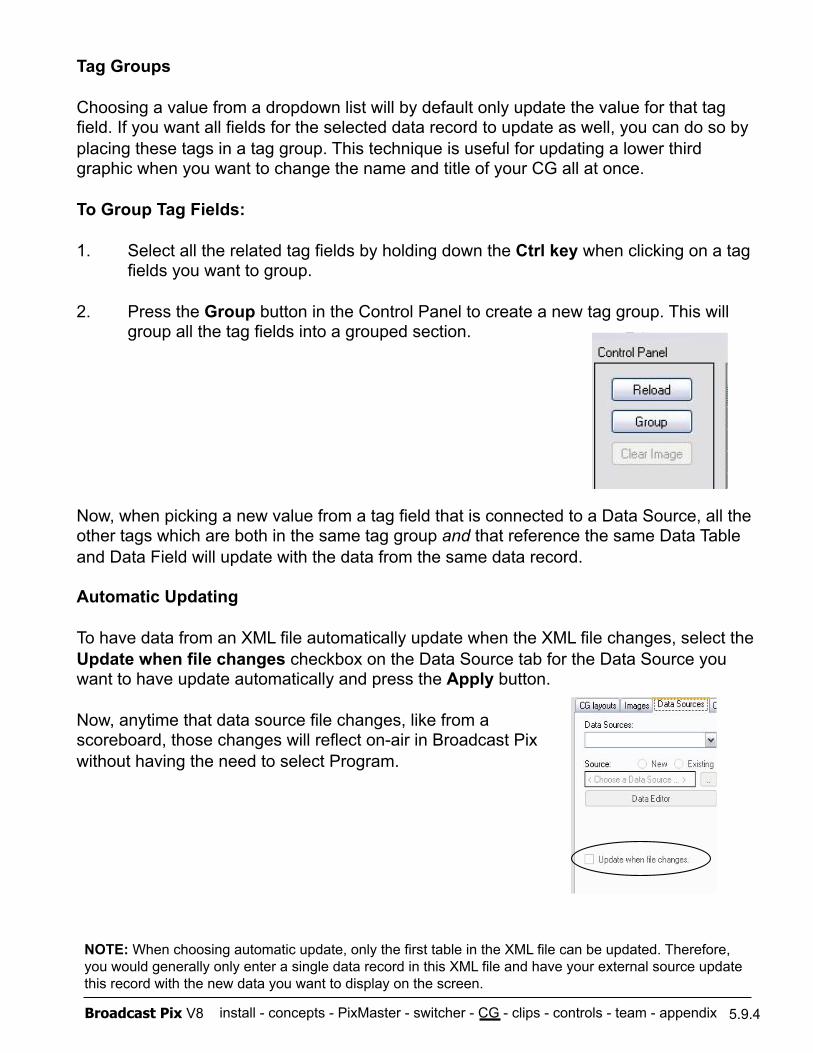
install - concepts - PixMaster - switcher - CG - clips - controls - team - appendix Broadcast Pix V8
Tag Groups
Choosing a value from a dropdown list will by default only update the value for that tag field. If you want all fields for the selected data record to update as well, you can do so by placing these tags in a tag group. This technique is useful for updating a lower third graphic when you want to change the name and title of your CG all at once.
To Group Tag Fields:
1. Select all the related tag fields by holding down the Ctrl key when clicking on a tag fields you want to group.
2. Press the Group button in the Control Panel to create a new tag group. This will group all the tag fields into a grouped section.
Now, when picking a new value from a tag field that is connected to a Data Source, all the other tags which are both in the same tag group and that reference the same Data Table and Data Field will update with the data from the same data record.
Automatic Updating
To have data from an XML file automatically update when the XML file changes, select the Update when file changes checkbox on the Data Source tab for the Data Source you want to have update automatically and press the Apply button.
Now, anytime that data source file changes, like from a scoreboard, those changes will reflect on-air in Broadcast Pix without having the need to select Program.
5.9.4
NOTE: When choosing automatic update, only the first table in the XML file can be updated. Therefore, you would generally only enter a single data record in this XML file and have your external source update this record with the new data you want to display on the screen.
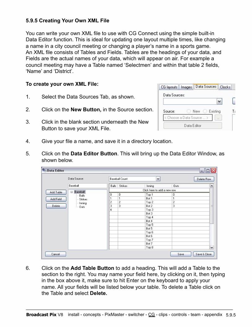
install - concepts - PixMaster - switcher - CG - clips - controls - team - appendix Broadcast Pix V8
5.9.5 Creating Your Own XML File
You can write your own XML file to use with CG Connect using the simple built-in Data Editor function. This is ideal for updating one layout multiple times, like changing a name in a city council meeting or changing a player’s name in a sports game. An XML file consists of Tables and Fields. Tables are the headings of your data, and Fields are the actual names of your data, which will appear on air. For example a council meeting may have a Table named ‘Selectmen’ and within that table 2 fields, ‘Name’ and ‘District’.
To create your own XML File:
1. Select the Data Sources Tab, as shown.
2. Click on the New Button, in the Source section.
3. Click in the blank section underneath the New Button to save your XML File.
4. Give your file a name, and save it in a directory location.
5. Click on the Data Editor Button. This will bring up the Data Editor Window, as shown below.
6. Click on the Add Table Button to add a heading. This will add a Table to the section to the right. You may name your field here, by clicking on it, then typing in the box above it, make sure to hit Enter on the keyboard to apply your name. All your fields will be listed below your table. To delete a Table click on the Table and select Delete.
5.9.5
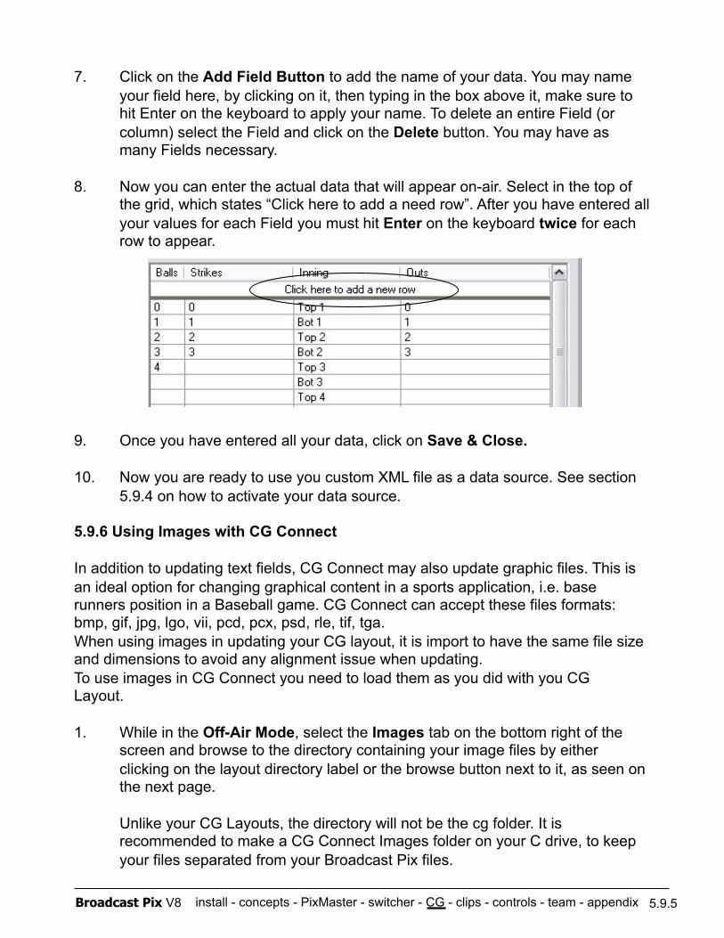
install - concepts - PixMaster - switcher - CG - clips - controls - team - appendix Broadcast Pix V8
7. Click on the Add Field Button to add the name of your data. You may name your field here, by clicking on it, then typing in the box above it, make sure to hit Enter on the keyboard to apply your name. To delete an entire Field (or column) select the Field and click on the Delete button. You may have as many Fields necessary.
8. Now you can enter the actual data that will appear on-air. Select in the top of the grid, which states “Click here to add a need row”. After you have entered all your values for each Field you must hit Enter on the keyboard twice for each row to appear.
9. Once you have entered all your data, click on Save & Close.
10. Now you are ready to use you custom XML file as a data source. See section 5.9.4 on how to activate your data source.
5.9.6 Using Images with CG Connect
In addition to updating text fields, CG Connect may also update graphic files. This is an ideal option for changing graphical content in a sports application, i.e. base runners position in a Baseball game. CG Connect can accept these files formats: bmp, gif, jpg, lgo, vii, pcd, pcx, psd, rle, tif, tga. When using images in updating your CG layout, it is import to have the same file size and dimensions to avoid any alignment issue when updating. To use images in CG Connect you need to load them as you did with you CG Layout.
1. While in the Off-Air Mode, select the Images tab on the bottom right of the screen and browse to the directory containing your image files by either clicking on the layout directory label or the browse button next to it, as seen on the next page.
Unlike your CG Layouts, the directory will not be the cg folder. It is recommended to make a CG Connect Images folder on your C drive, to keep your files separated from your Broadcast Pix files.
5.9.5
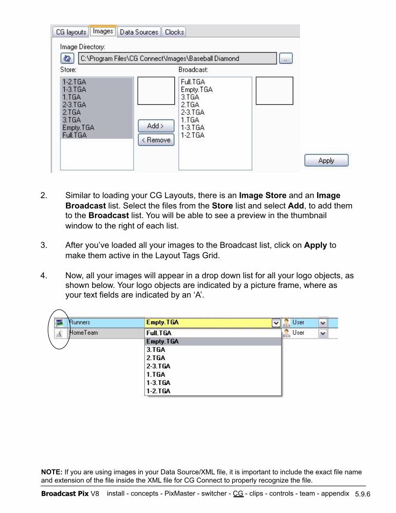
install - concepts - PixMaster - switcher - CG - clips - controls - team - appendix Broadcast Pix V8
2. Similar to loading your CG Layouts, there is an Image Store and an Image Broadcast list. Select the files from the Store list and select Add, to add them to the Broadcast list. You will be able to see a preview in the thumbnail window to the right of each list.
3. After you’ve loaded all your images to the Broadcast list, click on Apply to make them active in the Layout Tags Grid.
4. Now, all your images will appear in a drop down list for all your logo objects, as shown below. Your logo objects are indicated by a picture frame, where as your text fields are indicated by an ‘A’.
5.9.6
NOTE: If you are using images in your Data Source/XML file, it is important to include the exact file name and extension of the file inside the XML file for CG Connect to properly recognize the file.
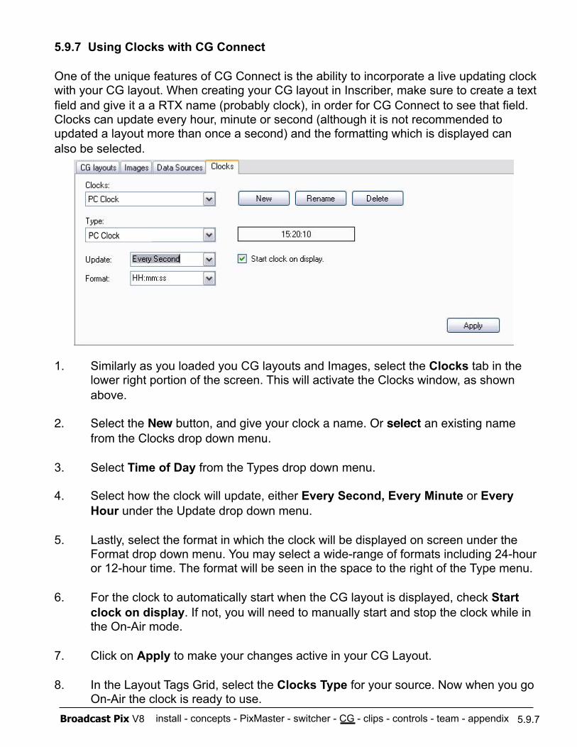
install - concepts - PixMaster - switcher - CG - clips - controls - team - appendix Broadcast Pix V8
5.9.7 Using Clocks with CG Connect
One of the unique features of CG Connect is the ability to incorporate a live updating clock with your CG layout. When creating your CG layout in Inscriber, make sure to create a text field and give it a a RTX name (probably clock), in order for CG Connect to see that field. Clocks can update every hour, minute or second (although it is not recommended to updated a layout more than once a second) and the formatting which is displayed can also be selected.
1. Similarly as you loaded you CG layouts and Images, select the Clocks tab in the lower right portion of the screen. This will activate the Clocks window, as shown above.
2. Select the New button, and give your clock a name. Or select an existing name from the Clocks drop down menu.
3. Select Time of Day from the Types drop down menu.
4. Select how the clock will update, either Every Second, Every Minute or Every Hour under the Update drop down menu.
5. Lastly, select the format in which the clock will be displayed on screen under the Format drop down menu. You may select a wide-range of formats including 24-hour or 12-hour time. The format will be seen in the space to the right of the Type menu.
6. For the clock to automatically start when the CG layout is displayed, check Start clock on display. If not, you will need to manually start and stop the clock while in the On-Air mode.
7. Click on Apply to make your changes active in your CG Layout.
8. In the Layout Tags Grid, select the Clocks Type for your source. Now when you go On-Air the clock is ready to use.
5.9.7
PC Clock
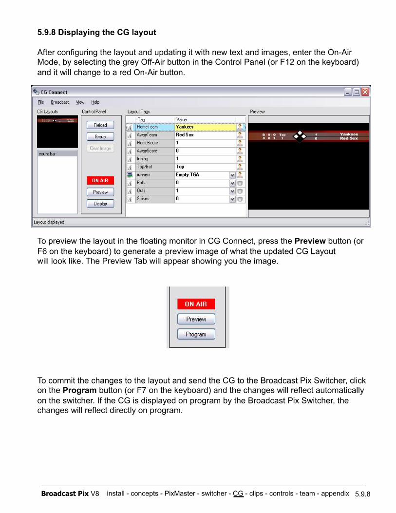
install - concepts - PixMaster - switcher - CG - clips - controls - team - appendix Broadcast Pix V8
5.9.8 Displaying the CG layout
After configuring the layout and updating it with new text and images, enter the On-Air Mode, by selecting the grey Off-Air button in the Control Panel (or F12 on the keyboard) and it will change to a red On-Air button.
To preview the layout in the floating monitor in CG Connect, press the Preview button (or F6 on the keyboard) to generate a preview image of what the updated CG Layout will look like. The Preview Tab will appear showing you the image.
To commit the changes to the layout and send the CG to the Broadcast Pix Switcher, click on the Program button (or F7 on the keyboard) and the changes will reflect automatically on the switcher. If the CG is displayed on program by the Broadcast Pix Switcher, the changes will reflect directly on program.
5.9.8
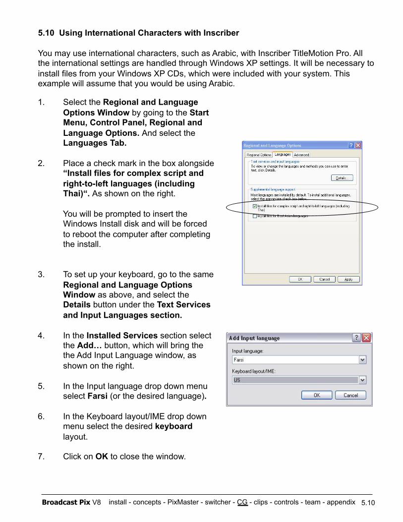
install - concepts - PixMaster - switcher - CG - clips - controls - team - appendix Broadcast Pix V8
5.10 Using International Characters with Inscriber
You may use international characters, such as Arabic, with Inscriber TitleMotion Pro. All the international settings are handled through Windows XP settings. It will be necessary to install files from your Windows XP CDs, which were included with your system. This example will assume that you would be using Arabic.
5.10
1. Select the Regional and Language Options Window by going to the Start Menu, Control Panel, Regional and Language Options. And select the Languages Tab.
2. Place a check mark in the box alongside “Install files for complex script and right-to-left languages (including Thai)“. As shown on the right.
You will be prompted to insert the Windows Install disk and will be forced to reboot the computer after completing the install.
3. To set up your keyboard, go to the same Regional and Language Options Window as above, and select the Details button under the Text Services and Input Languages section.
4. In the Installed Services section select the Add… button, which will bring the the Add Input Language window, as shown on the right.
5. In the Input language drop down menu select Farsi (or the desired language).
6. In the Keyboard layout/IME drop down menu select the desired keyboard layout.
7. Click on OK to close the window.
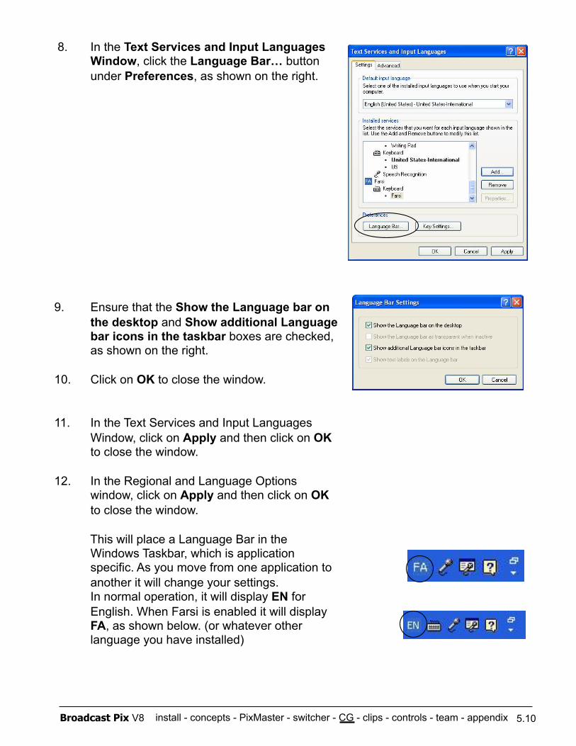
install - concepts - PixMaster - switcher - CG - clips - controls - team - appendix Broadcast Pix V8
8. In the Text Services and Input Languages Window, click the Language Bar… button under Preferences, as shown on the right.
9. Ensure that the Show the Language bar on the desktop and Show additional Language bar icons in the taskbar boxes are checked, as shown on the right.
10. Click on OK to close the window.
11. In the Text Services and Input Languages Window, click on Apply and then click on OK to close the window.
12. In the Regional and Language Options window, click on Apply and then click on OK to close the window.
This will place a Language Bar in the Windows Taskbar, which is application specific. As you move from one application to another it will change your settings. In normal operation, it will display EN for English. When Farsi is enabled it will display FA, as shown below. (or whatever other language you have installed)
5.10
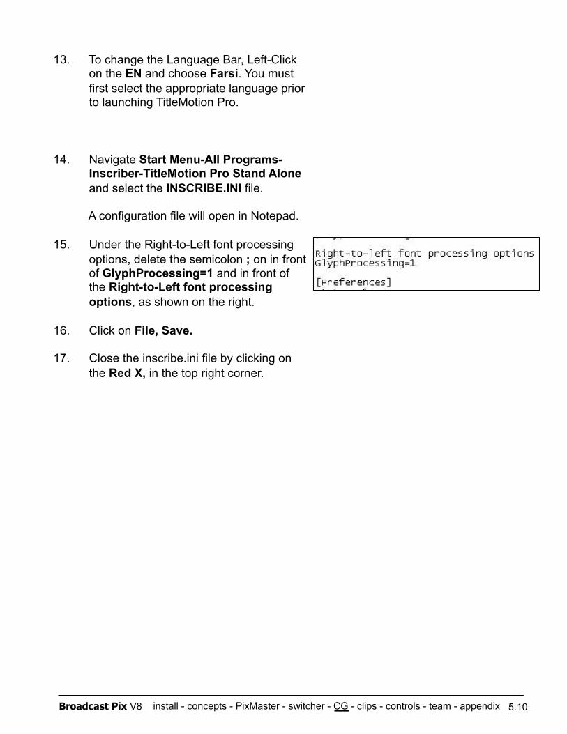
install - concepts - PixMaster - switcher - CG - clips - controls - team - appendix Broadcast Pix V8
13. To change the Language Bar, Left-Click on the EN and choose Farsi. You must first select the appropriate language prior to launching TitleMotion Pro.
14. Navigate Start Menu-All Programs-Inscriber-TitleMotion Pro Stand Alone and select the INSCRIBE.INI file.
A configuration file will open in Notepad.
15. Under the Right-to-Left font processing options, delete the semicolon ; on in front of GlyphProcessing=1 and in front of the Right-to-Left font processing options, as shown on the right.
16. Click on File, Save.
17. Close the inscribe.ini file by clicking on the Red X, in the top right corner.
5.10
install - concepts - PixMaster - switcher - CG - clips - controls - team - appendix Broadcast Pix V8
The Broadcast Pix system contains a two channel clip store (digital disk recorder). Clips can be recorded in an uncompressed digital format in pre-production and then played out during a show. Additionally, the clip store may also play compressed clips, such as a QuickTime movie files, as described in section 6.3.4, and import animation sequences in many formats for playout of animated titles and backgrounds with and without audio as described in section 5.4.2. As an option, the Broadcast Pix system can also control external DDRs/Servers, as described in section 6.7.
There are 2 options available for the Broadcast Pix clip store: - a second channel to play 2 clips at once (standard on Slate 2100G & 3000G) - more capacity to double the space of the clipstore
6.0.1 Audio Flow with Embedded Audio
All SD Slate Switcher systems support the recording and playback of audio that is embedded in the SD-SDI stream, such as from a digital VTR. On a 2100G the iBoB acts as a de-embedder. To enable embedded audio see section 1.4
Playing Embedded Audio
On a Slate 100G, 1000G and 3000G all Slate SD-SDI video outputs can be assigned to playback embedded audio on clip 1 or clip 2, this is configured in the Slate I/O Assignments window, see section 1.5 for more information.
On a 2100G embedded audio is automatically outputted on the Preview and Program SDI stream on the Break-out-Box (iBoB). Clip 1 is embedded on Program and Clip 2 is embedded on Preview. If desired, you may also use the extra outputs D and/or E from the Slate cards as described for a 100G/1000G.
6.0
Section 6: Clip Store
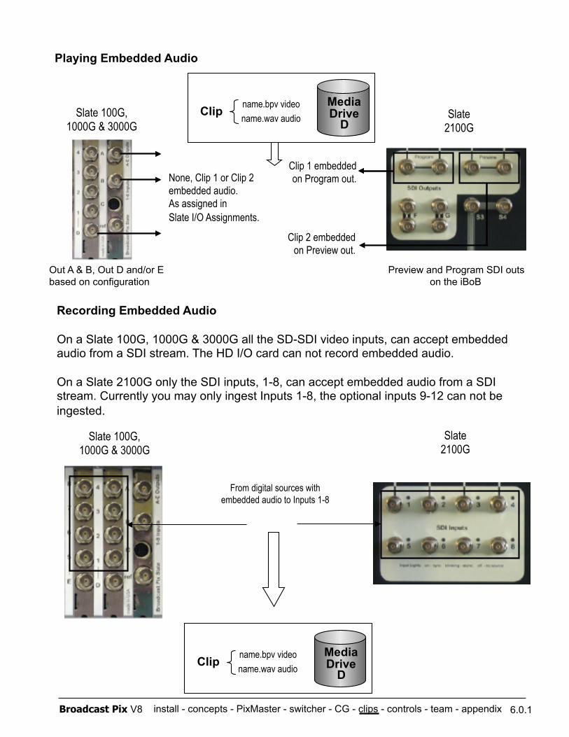
install - concepts - PixMaster - switcher - CG - clips - controls - team - appendix Broadcast Pix V8 6.0.1
Out A & B, Out D and/or E based on configuration
None, Clip 1 or Clip 2 embedded audio. As assigned in Slate I/O Assignments.
Media Drive
D name.wav audio name.bpv video Clip Slate 100G,
1000G & 3000G Slate
2100G
Preview and Program SDI outs on the iBoB
Clip 1 embedded on Program out.
Clip 2 embedded on Preview out.
Playing Embedded Audio
Recording Embedded Audio
On a Slate 100G, 1000G & 3000G all the SD-SDI video inputs, can accept embedded audio from a SDI stream. The HD I/O card can not record embedded audio.
On a Slate 2100G only the SDI inputs, 1-8, can accept embedded audio from a SDI stream. Currently you may only ingest Inputs 1-8, the optional inputs 9-12 can not be ingested.
Media Drive
D name.wav audio name.bpv video Clip
Slate 100G, 1000G & 3000G
Slate 2100G
From digital sources with embedded audio to Inputs 1-8
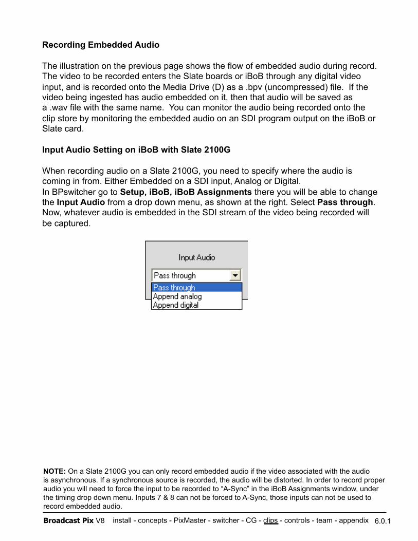
install - concepts - PixMaster - switcher - CG - clips - controls - team - appendix Broadcast Pix V8 6.0.1
Recording Embedded Audio
The illustration on the previous page shows the flow of embedded audio during record. The video to be recorded enters the Slate boards or iBoB through any digital video input, and is recorded onto the Media Drive (D) as a .bpv (uncompressed) file. If the video being ingested has audio embedded on it, then that audio will be saved as a .wav file with the same name. You can monitor the audio being recorded onto the clip store by monitoring the embedded audio on an SDI program output on the iBoB or Slate card.
Input Audio Setting on iBoB with Slate 2100G
When recording audio on a Slate 2100G, you need to specify where the audio is coming in from. Either Embedded on a SDI input, Analog or Digital. In BPswitcher go to Setup, iBoB, iBoB Assignments there you will be able to change the Input Audio from a drop down menu, as shown at the right. Select Pass through. Now, whatever audio is embedded in the SDI stream of the video being recorded will be captured.
NOTE: On a Slate 2100G you can only record embedded audio if the video associated with the audio is asynchronous. If a synchronous source is recorded, the audio will be distorted. In order to record proper audio you will need to force the input to be recorded to “A-Sync” in the iBoB Assignments window, under the timing drop down menu. Inputs 7 & 8 can not be forced to A-Sync, those inputs can not be used to record embedded audio.
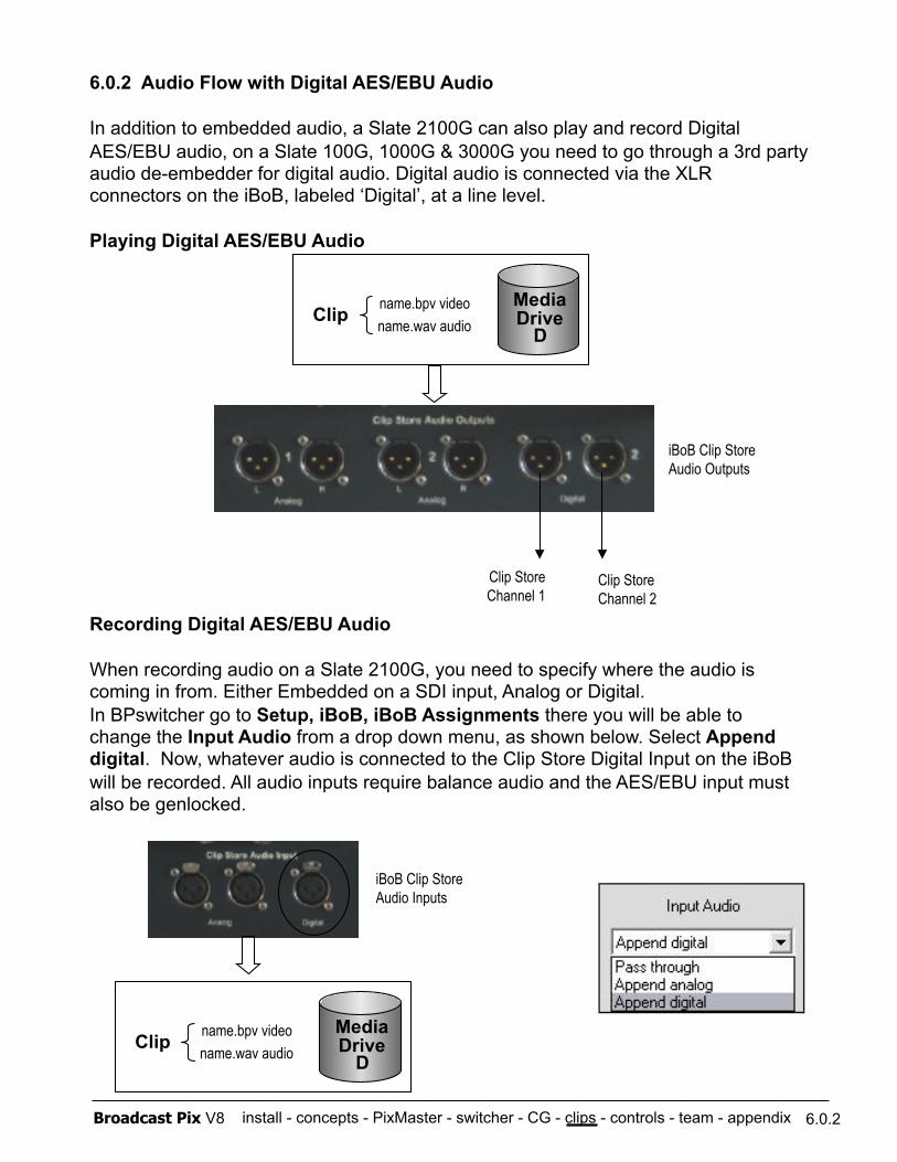
install - concepts - PixMaster - switcher - CG - clips - controls - team - appendix Broadcast Pix V8
6.0.2 Audio Flow with Digital AES/EBU Audio
In addition to embedded audio, a Slate 2100G can also play and record Digital AES/EBU audio, on a Slate 100G, 1000G & 3000G you need to go through a 3rd party audio de-embedder for digital audio. Digital audio is connected via the XLR connectors on the iBoB, labeled ‘Digital’, at a line level.
Playing Digital AES/EBU Audio
Recording Digital AES/EBU Audio
When recording audio on a Slate 2100G, you need to specify where the audio is coming in from. Either Embedded on a SDI input, Analog or Digital. In BPswitcher go to Setup, iBoB, iBoB Assignments there you will be able to change the Input Audio from a drop down menu, as shown below. Select Append digital. Now, whatever audio is connected to the Clip Store Digital Input on the iBoB will be recorded. All audio inputs require balance audio and the AES/EBU input must also be genlocked.
6.0.2
Clip Store Channel 1
Media Drive
D name.wav audio name.bpv video Clip
Clip Store Channel 2
Media Drive
D name.wav audio name.bpv video Clip
iBoB Clip Store Audio Outputs
iBoB Clip Store Audio Inputs
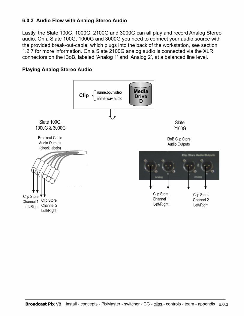
install - concepts - PixMaster - switcher - CG - clips - controls - team - appendix Broadcast Pix V8
6.0.3 Audio Flow with Analog Stereo Audio
Lastly, the Slate 100G, 1000G, 2100G and 3000G can all play and record Analog Stereo audio. On a Slate 100G, 1000G and 3000G you need to connect your audio source with the provided break-out-cable, which plugs into the back of the workstation, see section 1.2.7 for more information. On a Slate 2100G analog audio is connected via the XLR connectors on the iBoB, labeled ‘Analog 1’ and ‘Analog 2’, at a balanced line level.
Playing Analog Stereo Audio
6.0.3
Clip Store Channel 1 Left/Right
Clip Store Channel 2 Left/Right
iBoB Clip Store Audio Outputs
Slate 100G, 1000G & 3000G
Slate 2100G
Breakout Cable Audio Outputs (check labels)
Clip Store Channel 1 Left/Right
Clip Store Channel 2 Left/Right
Media Drive
D name.wav audio name.bpv video Clip
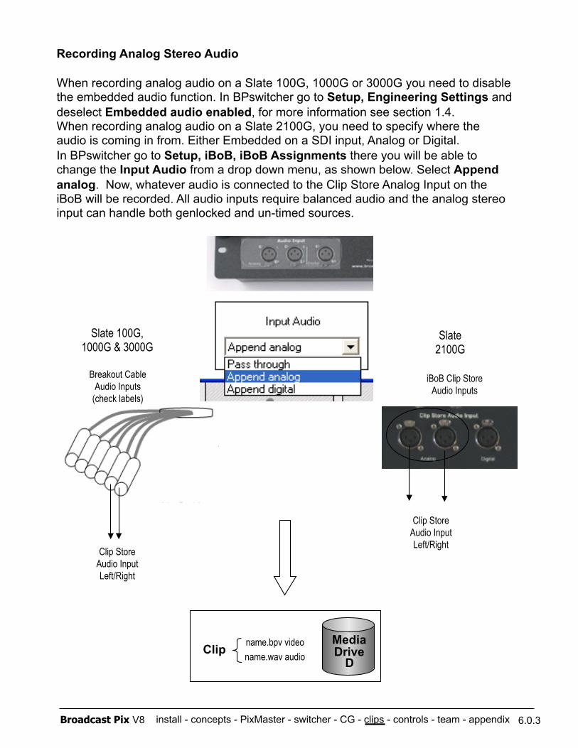
install - concepts - PixMaster - switcher - CG - clips - controls - team - appendix Broadcast Pix V8 6.0.3
Recording Analog Stereo Audio
When recording analog audio on a Slate 100G, 1000G or 3000G you need to disable the embedded audio function. In BPswitcher go to Setup, Engineering Settings and deselect Embedded audio enabled, for more information see section 1.4. When recording analog audio on a Slate 2100G, you need to specify where the audio is coming in from. Either Embedded on a SDI input, Analog or Digital. In BPswitcher go to Setup, iBoB, iBoB Assignments there you will be able to change the Input Audio from a drop down menu, as shown below. Select Append analog. Now, whatever audio is connected to the Clip Store Analog Input on the iBoB will be recorded. All audio inputs require balanced audio and the analog stereo input can handle both genlocked and un-timed sources.
Media Drive
D name.wav audio name.bpv video Clip
Slate 100G, 1000G & 3000G
Slate 2100G
Breakout Cable Audio Inputs
(check labels)
Clip Store Audio Input Left/Right
iBoB Clip Store Audio Inputs
Clip Store Audio Input Left/Right
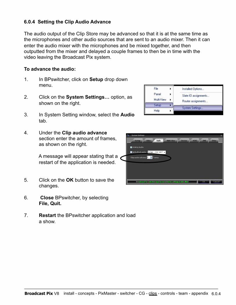
install - concepts - PixMaster - switcher - CG - clips - controls - team - appendix Broadcast Pix V8
6.0.4 Setting the Clip Audio Advance
The audio output of the Clip Store may be advanced so that it is at the same time as the microphones and other audio sources that are sent to an audio mixer. Then it can enter the audio mixer with the microphones and be mixed together, and then outputted from the mixer and delayed a couple frames to then be in time with the video leaving the Broadcast Pix system.
To advance the audio:
1. In BPswitcher, click on Setup drop down menu.
2. Click on the System Settings… option, as shown on the right.
3. In System Setting window, select the Audio tab.
4. Under the Clip audio advance section enter the amount of frames, as shown on the right.
A message will appear stating that a restart of the application is needed.
5. Click on the OK button to save the changes.
6. Close BPswitcher, by selecting File, Quit.
7. Restart the BPswitcher application and load a show.
6.0.4
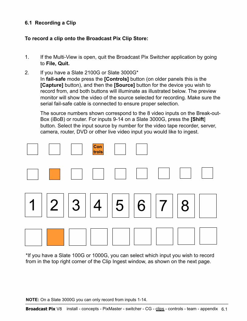
install - concepts - PixMaster - switcher - CG - clips - controls - team - appendix Broadcast Pix V8
6.1 Recording a Clip
To record a clip onto the Broadcast Pix Clip Store:
1. If the Multi-View is open, quit the Broadcast Pix Switcher application by going to File, Quit.
2. If you have a Slate 2100G or Slate 3000G* In fail-safe mode press the [Controls] button (on older panels this is the [Capture] button), and then the [Source] button for the device you wish to record from, and both buttons will illuminate as illustrated below. The preview monitor will show the video of the source selected for recording. Make sure the serial fail-safe cable is connected to ensure proper selection.
The source numbers shown correspond to the 8 video inputs on the Break-out-Box (iBoB) or router. For inputs 9-14 on a Slate 3000G, press the [Shift] button. Select the input source by number for the video tape recorder, server, camera, router, DVD or other live video input you would like to ingest.
6.1
1 2 3 4 5 6 7 8
Con trols
*If you have a Slate 100G or 1000G, you can select which input you wish to record from in the top right corner of the Clip Ingest window, as shown on the next page.
NOTE: On a Slate 3000G you can only record from inputs 1-14.
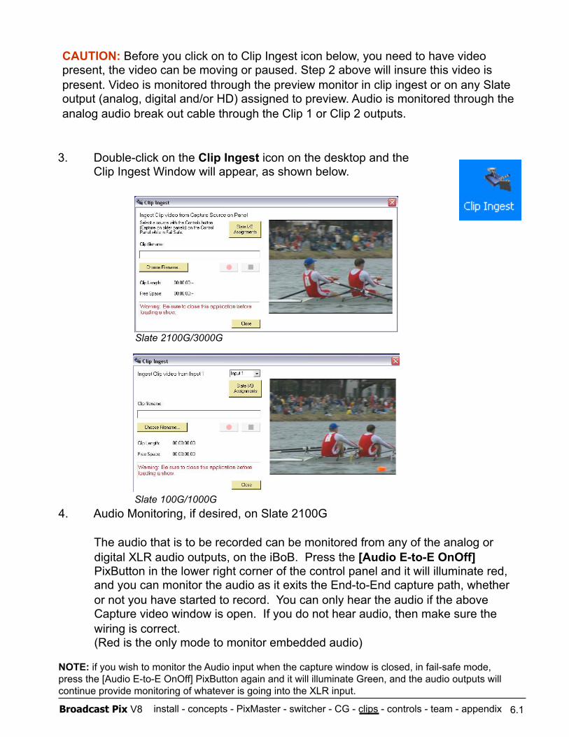
install - concepts - PixMaster - switcher - CG - clips - controls - team - appendix Broadcast Pix V8 6.1
4. Audio Monitoring, if desired, on Slate 2100G
The audio that is to be recorded can be monitored from any of the analog or digital XLR audio outputs, on the iBoB. Press the [Audio E-to-E OnOff] PixButton in the lower right corner of the control panel and it will illuminate red, and you can monitor the audio as it exits the End-to-End capture path, whether or not you have started to record. You can only hear the audio if the above Capture video window is open. If you do not hear audio, then make sure the wiring is correct. (Red is the only mode to monitor embedded audio)
NOTE: if you wish to monitor the Audio input when the capture window is closed, in fail-safe mode, press the [Audio E-to-E OnOff] PixButton again and it will illuminate Green, and the audio outputs will continue provide monitoring of whatever is going into the XLR input.
3. Double-click on the Clip Ingest icon on the desktop and the Clip Ingest Window will appear, as shown below.
CAUTION: Before you click on to Clip Ingest icon below, you need to have video present, the video can be moving or paused. Step 2 above will insure this video is present. Video is monitored through the preview monitor in clip ingest or on any Slate output (analog, digital and/or HD) assigned to preview. Audio is monitored through the analog audio break out cable through the Clip 1 or Clip 2 outputs.
Slate 100G/1000G
Slate 2100G/3000G
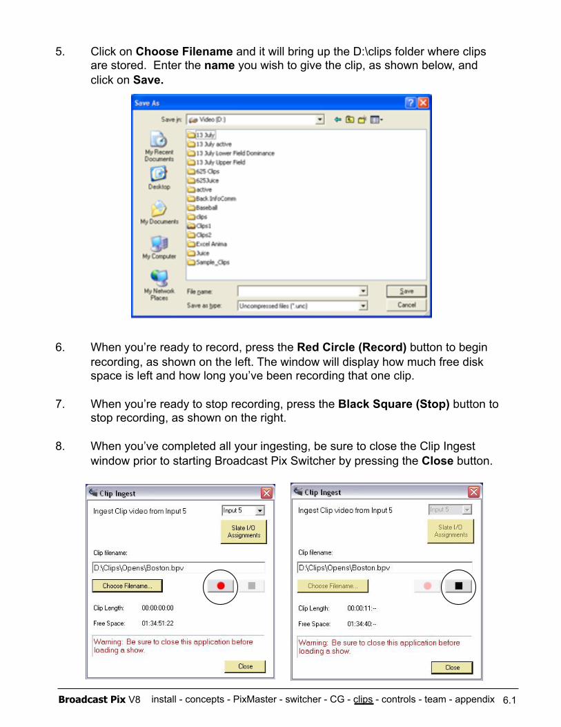
install - concepts - PixMaster - switcher - CG - clips - controls - team - appendix Broadcast Pix V8
5. Click on Choose Filename and it will bring up the D:\clips folder where clips are stored. Enter the name you wish to give the clip, as shown below, and click on Save.
6. When you’re ready to record, press the Red Circle (Record) button to begin recording, as shown on the left. The window will display how much free disk space is left and how long you’ve been recording that one clip.
7. When you’re ready to stop recording, press the Black Square (Stop) button to stop recording, as shown on the right.
8. When you’ve completed all your ingesting, be sure to close the Clip Ingest window prior to starting Broadcast Pix Switcher by pressing the Close button.
6.1
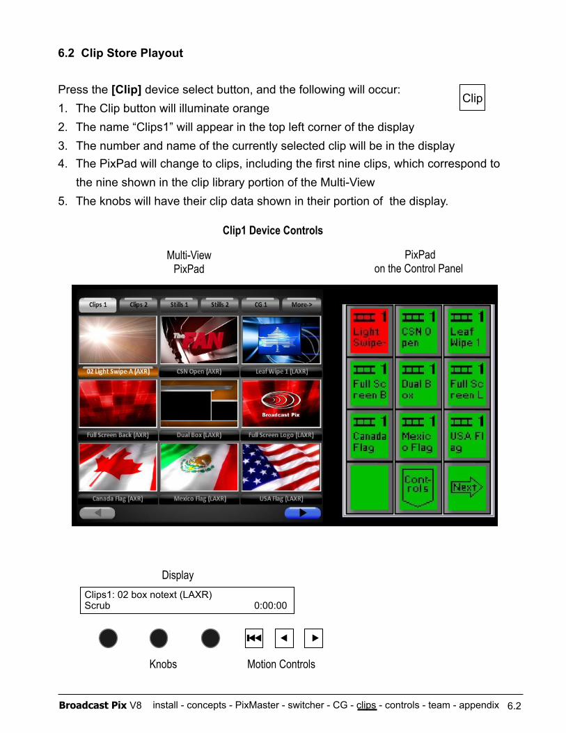
install - concepts - PixMaster - switcher - CG - clips - controls - team - appendix Broadcast Pix V8
6.2 Clip Store Playout
Press the [Clip] device select button, and the following will occur: 1. The Clip button will illuminate orange 2. The name “Clips1” will appear in the top left corner of the display 3. The number and name of the currently selected clip will be in the display 4. The PixPad will change to clips, including the first nine clips, which correspond to
the nine shown in the clip library portion of the Multi-View 5. The knobs will have their clip data shown in their portion of the display.
Clips1: 02 box notext (LAXR) Scrub 0:00:00
PixPad on the Control Panel
Display
Knobs Motion Controls
Multi-View PixPad
Clip1 Device Controls
6.2
Clip
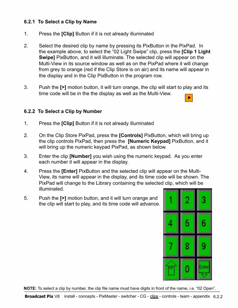
install - concepts - PixMaster - switcher - CG - clips - controls - team - appendix Broadcast Pix V8
6.2.1 To Select a Clip by Name
1. Press the [Clip] Button if it is not already illuminated
2. Select the desired clip by name by pressing its PixButton in the PixPad. In the example above, to select the “02 Light Swipe” clip, press the [Clip 1 Light Swipe] PixButton, and it will illuminate. The selected clip will appear on the Multi-View in its source window as well as on the PixPad where it will change from grey to orange (red if the Clip Store is on air) and its name will appear in the display and in the Clip PixButton in the program row.
3. Push the [>] motion button, it will turn orange, the clip will start to play and its time code will be in the the display as well as the Multi-View.
6.2.2 To Select a Clip by Number
1. Press the [Clip] Button if it is not already illuminated
2. On the Clip Store PixPad, press the [Controls] PixButton, which will bring up the clip controls PixPad, then press the [Numeric Keypad] PixButton, and it will bring up the numeric keypad PixPad, as shown below.
3. Enter the clip [Number] you wish using the numeric keypad. As you enter each number it will appear in the display.
4. Press the [Enter] PixButton and the selected clip will appear on the Multi-View, its name will appear in the display, and its time code will be shown. The PixPad will change to the Library containing the selected clip, which will be illuminated.
5. Push the [>] motion button, and it will turn orange and the clip will start to play, and its time code will advance.
6.2.2
NOTE: To select a clip by number, the clip file name must have digits in front of the name, i.e. “02 Open”.
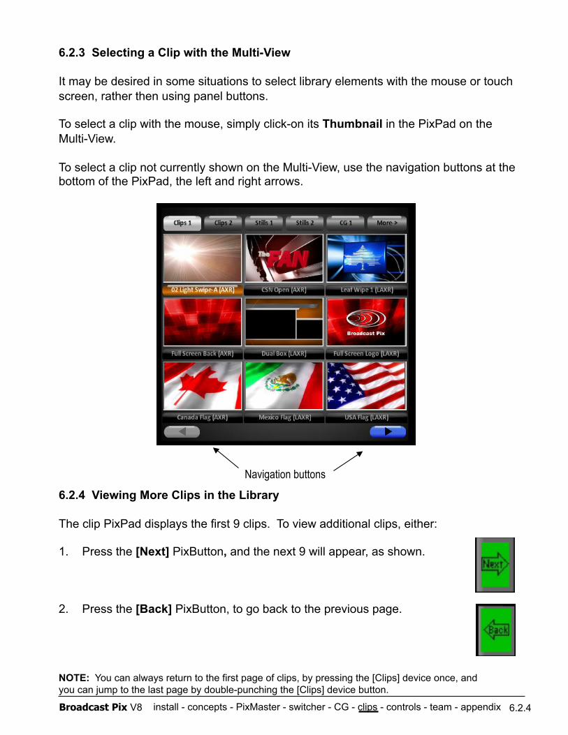
install - concepts - PixMaster - switcher - CG - clips - controls - team - appendix Broadcast Pix V8
6.2.3 Selecting a Clip with the Multi-View
It may be desired in some situations to select library elements with the mouse or touch screen, rather then using panel buttons.
To select a clip with the mouse, simply click-on its Thumbnail in the PixPad on the Multi-View.
To select a clip not currently shown on the Multi-View, use the navigation buttons at the bottom of the PixPad, the left and right arrows.
6.2.4 Viewing More Clips in the Library
The clip PixPad displays the first 9 clips. To view additional clips, either:
1. Press the [Next] PixButton, and the next 9 will appear, as shown.
2. Press the [Back] PixButton, to go back to the previous page.
NOTE: You can always return to the first page of clips, by pressing the [Clips] device once, and you can jump to the last page by double-punching the [Clips] device button.
Navigation buttons
6.2.4
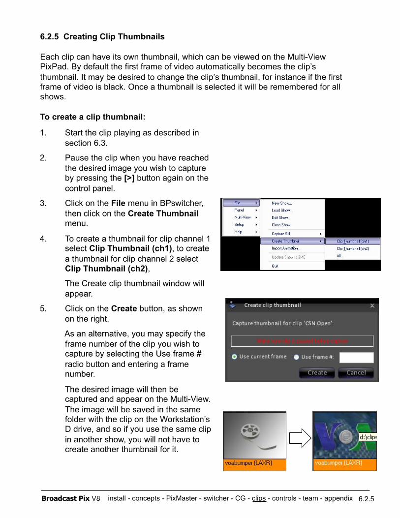
install - concepts - PixMaster - switcher - CG - clips - controls - team - appendix Broadcast Pix V8
1. Start the clip playing as described in section 6.3.
2. Pause the clip when you have reached the desired image you wish to capture by pressing the [>] button again on the control panel.
3. Click on the File menu in BPswitcher, then click on the Create Thumbnail menu.
4. To create a thumbnail for clip channel 1 select Clip Thumbnail (ch1), to create a thumbnail for clip channel 2 select Clip Thumbnail (ch2),
The Create clip thumbnail window will appear.
5. Click on the Create button, as shown on the right.
As an alternative, you may specify the frame number of the clip you wish to capture by selecting the Use frame # radio button and entering a frame number.
The desired image will then be captured and appear on the Multi-View. The image will be saved in the same folder with the clip on the Workstation’s D drive, and so if you use the same clip in another show, you will not have to create another thumbnail for it.
6.2.5 Creating Clip Thumbnails
Each clip can have its own thumbnail, which can be viewed on the Multi-View PixPad. By default the first frame of video automatically becomes the clip’s thumbnail. It may be desired to change the clip’s thumbnail, for instance if the first frame of video is black. Once a thumbnail is selected it will be remembered for all shows.
To create a clip thumbnail:
6.2.5
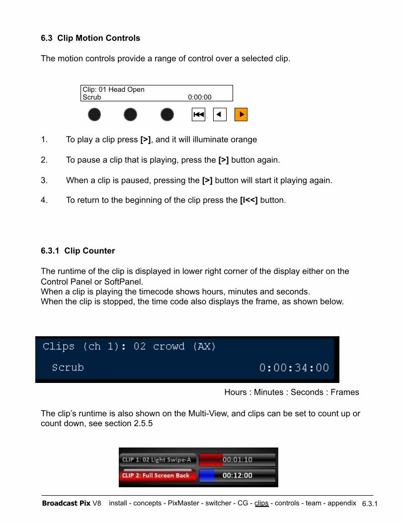
install - concepts - PixMaster - switcher - CG - clips - controls - team - appendix Broadcast Pix V8
6.3 Clip Motion Controls
The motion controls provide a range of control over a selected clip.
1. To play a clip press [>], and it will illuminate orange
2. To pause a clip that is playing, press the [>] button again.
3. When a clip is paused, pressing the [>] button will start it playing again. 4. To return to the beginning of the clip press the [l<<] button.
6.3.1 Clip Counter
The runtime of the clip is displayed in lower right corner of the display either on the Control Panel or SoftPanel. When a clip is playing the timecode shows hours, minutes and seconds. When the clip is stopped, the time code also displays the frame, as shown below.
The clip’s runtime is also shown on the Multi-View, and clips can be set to count up or count down, see section 2.5.5
6.3.1
Clip: 01 Head Open Scrub 0:00:00
Hours : Minutes : Seconds : Frames
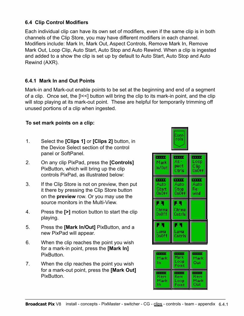
install - concepts - PixMaster - switcher - CG - clips - controls - team - appendix Broadcast Pix V8
6.4 Clip Control Modifiers
Each individual clip can have its own set of modifiers, even if the same clip is in both channels of the Clip Store, you may have different modifiers in each channel. Modifiers include: Mark In, Mark Out, Aspect Controls, Remove Mark In, Remove Mark Out, Loop Clip, Auto Start, Auto Stop and Auto Rewind. When a clip is ingested and added to a show the clip is set up by default to Auto Start, Auto Stop and Auto Rewind (AXR).
6.4.1 Mark In and Out Points
Mark-in and Mark-out enable points to be set at the beginning and end of a segment of a clip. Once set, the [l<<] button will bring the clip to its mark-in point, and the clip will stop playing at its mark-out point. These are helpful for temporarily trimming off unused portions of a clip when ingested.
To set mark points on a clip:
1. Select the [Clips 1] or [Clips 2] button, in the Device Select section of the control panel or SoftPanel.
2. On any clip PixPad, press the [Controls] PixButton, which will bring up the clip controls PixPad, as illustrated below:
3. If the Clip Store is not on preview, then put it there by pressing the Clip Store button on the preview row. Or you may use the source monitors in the Multi-View.
4. Press the [>] motion button to start the clip playing.
5. Press the [Mark In/Out] PixButton, and a new PixPad will appear.
6. When the clip reaches the point you wish for a mark-in point, press the [Mark In] PixButton.
7. When the clip reaches the point you wish for a mark-out point, press the [Mark Out] PixButton.
6.4.1
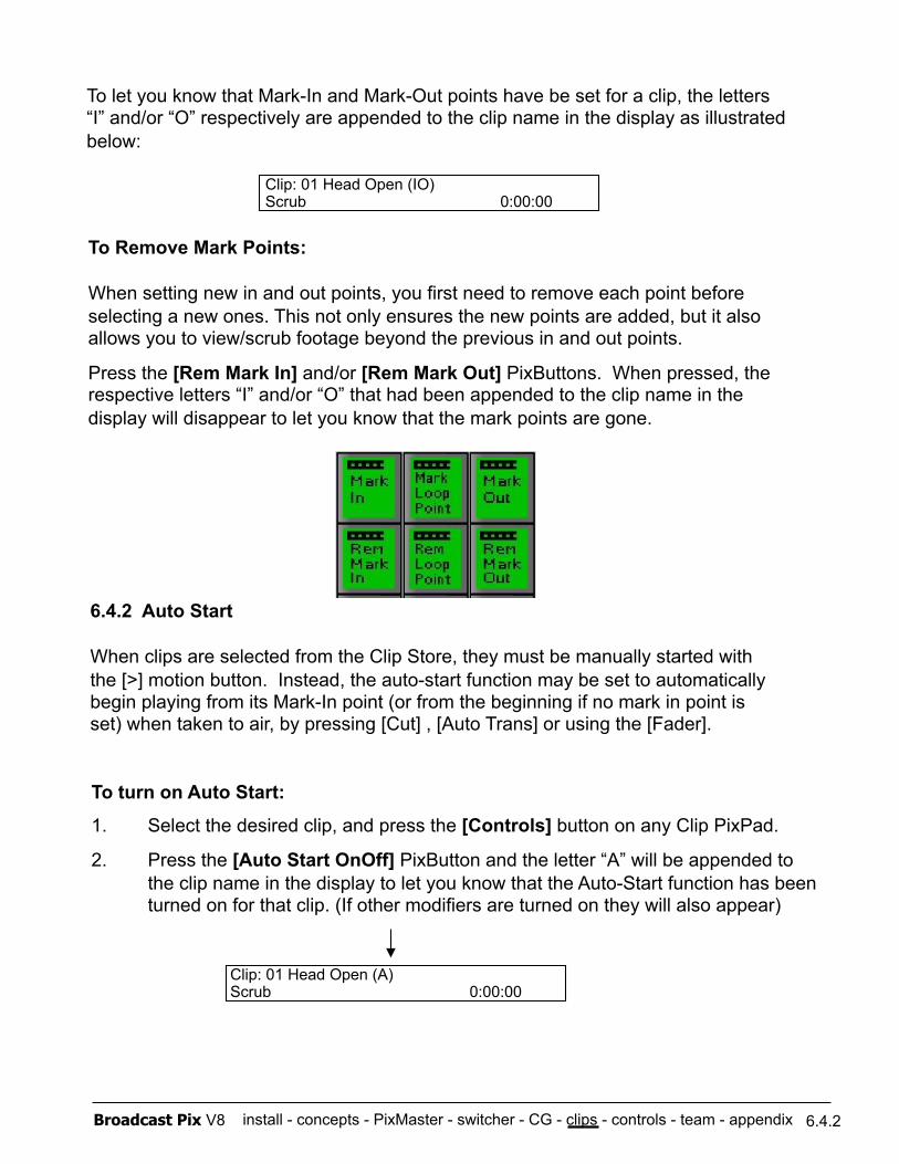
install - concepts - PixMaster - switcher - CG - clips - controls - team - appendix Broadcast Pix V8
To Remove Mark Points:
When setting new in and out points, you first need to remove each point before selecting a new ones. This not only ensures the new points are added, but it also allows you to view/scrub footage beyond the previous in and out points.
Press the [Rem Mark In] and/or [Rem Mark Out] PixButtons. When pressed, the respective letters “I” and/or “O” that had been appended to the clip name in the display will disappear to let you know that the mark points are gone.
6.4.2 Auto Start
When clips are selected from the Clip Store, they must be manually started with the [>] motion button. Instead, the auto-start function may be set to automatically begin playing from its Mark-In point (or from the beginning if no mark in point is set) when taken to air, by pressing [Cut] , [Auto Trans] or using the [Fader].
To turn on Auto Start:
1. Select the desired clip, and press the [Controls] button on any Clip PixPad.
2. Press the [Auto Start OnOff] PixButton and the letter “A” will be appended to the clip name in the display to let you know that the Auto-Start function has been turned on for that clip. (If other modifiers are turned on they will also appear)
6.4.2
Clip: 01 Head Open (A) Scrub 0:00:00
To let you know that Mark-In and Mark-Out points have be set for a clip, the letters “I” and/or “O” respectively are appended to the clip name in the display as illustrated below:
Clip: 01 Head Open (IO) Scrub 0:00:00
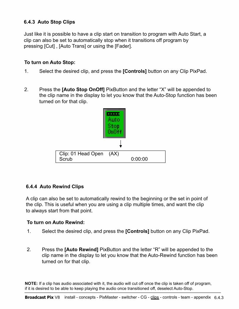
install - concepts - PixMaster - switcher - CG - clips - controls - team - appendix Broadcast Pix V8
6.4.3 Auto Stop Clips
Just like it is possible to have a clip start on transition to program with Auto Start, a clip can also be set to automatically stop when it transitions off program by pressing [Cut] , [Auto Trans] or using the [Fader].
To turn on Auto Stop:
1. Select the desired clip, and press the [Controls] button on any Clip PixPad.
2. Press the [Auto Stop OnOff] PixButton and the letter “X” will be appended to the clip name in the display to let you know that the Auto-Stop function has been turned on for that clip.
6.4.3
NOTE: If a clip has audio associated with it, the audio will cut off once the clip is taken off of program, if it is desired to be able to keep playing the audio once transitioned off, deselect Auto-Stop.
Clip: 01 Head Open (AX) Scrub 0:00:00
6.4.4 Auto Rewind Clips
A clip can also be set to automatically rewind to the beginning or the set in point of the clip. This is useful when you are using a clip multiple times, and want the clip to always start from that point.
To turn on Auto Rewind:
1. Select the desired clip, and press the [Controls] button on any Clip PixPad.
2. Press the [Auto Rewind] PixButton and the letter “R” will be appended to the clip name in the display to let you know that the Auto-Rewind function has been turned on for that clip.
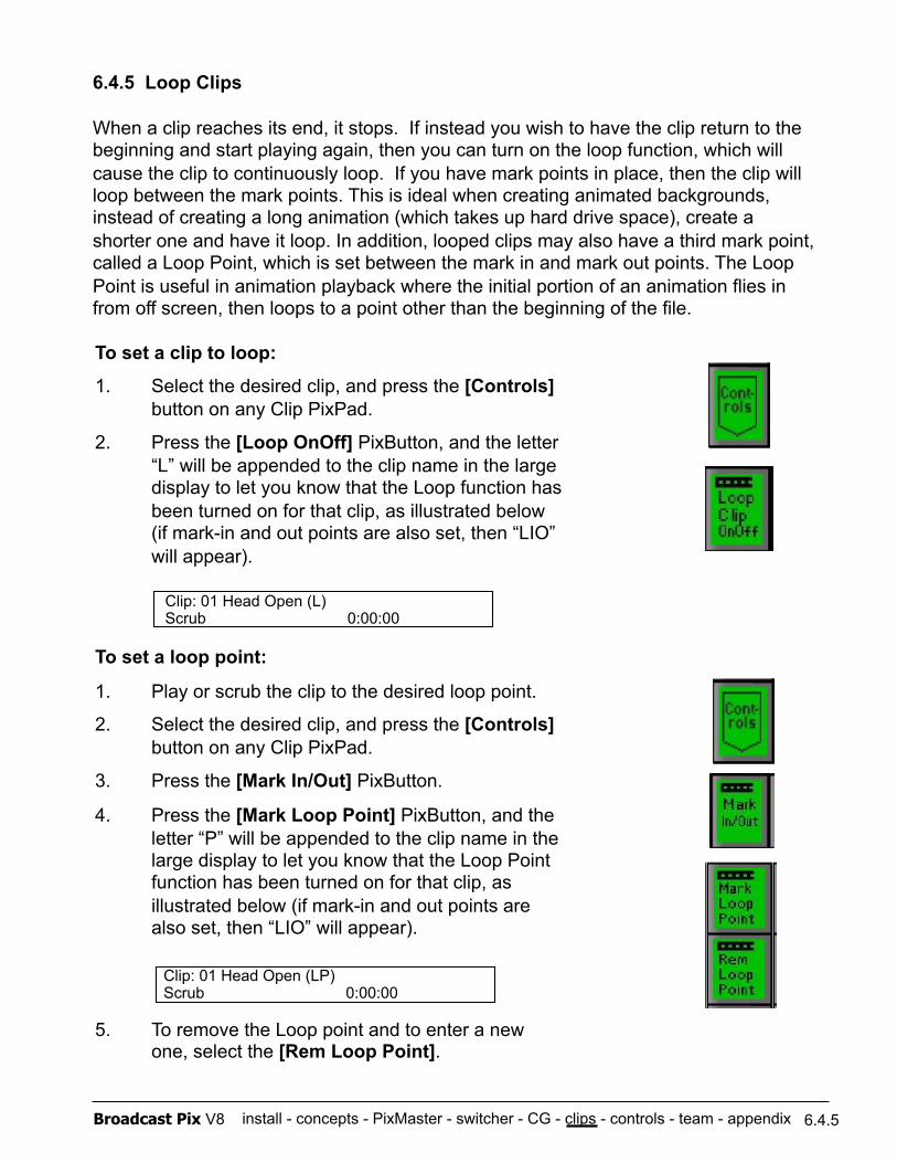
install - concepts - PixMaster - switcher - CG - clips - controls - team - appendix Broadcast Pix V8
To set a clip to loop:
1. Select the desired clip, and press the [Controls] button on any Clip PixPad.
2. Press the [Loop OnOff] PixButton, and the letter “L” will be appended to the clip name in the large display to let you know that the Loop function has been turned on for that clip, as illustrated below (if mark-in and out points are also set, then “LIO” will appear).
To set a loop point:
1. Play or scrub the clip to the desired loop point.
2. Select the desired clip, and press the [Controls] button on any Clip PixPad.
3. Press the [Mark In/Out] PixButton.
4. Press the [Mark Loop Point] PixButton, and the letter “P” will be appended to the clip name in the large display to let you know that the Loop Point function has been turned on for that clip, as illustrated below (if mark-in and out points are also set, then “LIO” will appear).
5. To remove the Loop point and to enter a new one, select the [Rem Loop Point].
6.4.5 Loop Clips
When a clip reaches its end, it stops. If instead you wish to have the clip return to the beginning and start playing again, then you can turn on the loop function, which will cause the clip to continuously loop. If you have mark points in place, then the clip will loop between the mark points. This is ideal when creating animated backgrounds, instead of creating a long animation (which takes up hard drive space), create a shorter one and have it loop. In addition, looped clips may also have a third mark point, called a Loop Point, which is set between the mark in and mark out points. The Loop Point is useful in animation playback where the initial portion of an animation flies in from off screen, then loops to a point other than the beginning of the file.
6.4.5
Clip: 01 Head Open (L) Scrub 0:00:00
Clip: 01 Head Open (LP) Scrub 0:00:00
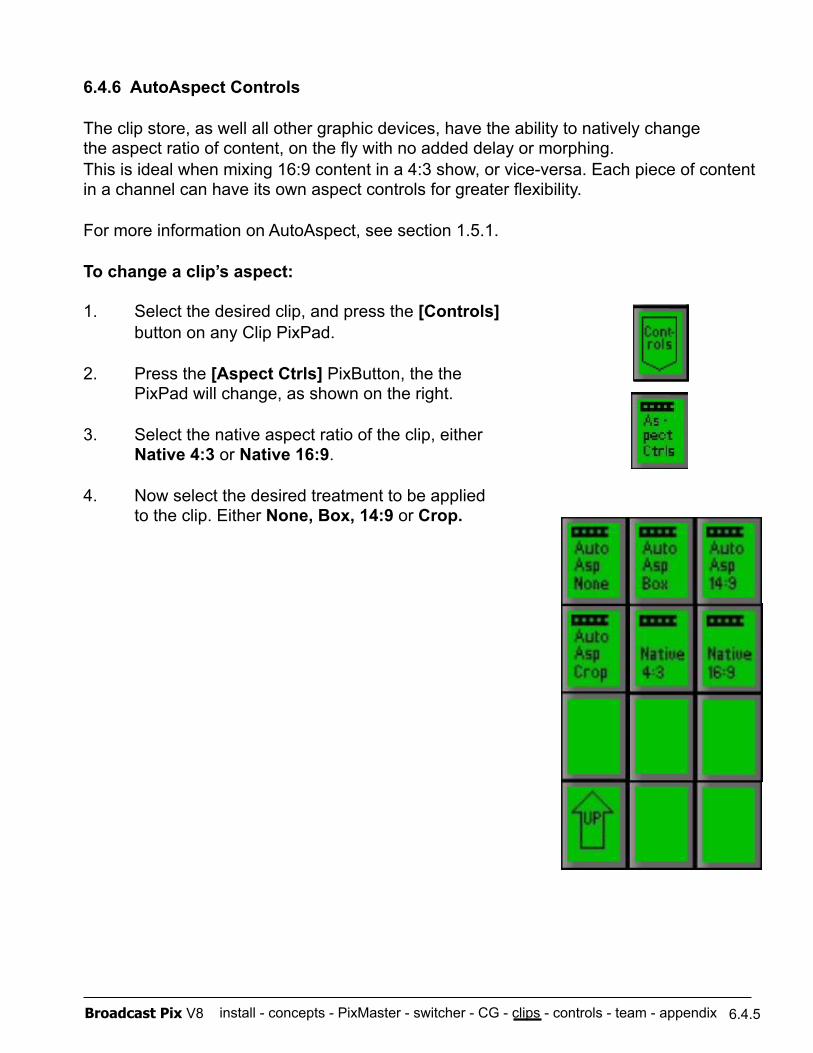
install - concepts - PixMaster - switcher - CG - clips - controls - team - appendix Broadcast Pix V8
6.4.6 AutoAspect Controls
The clip store, as well all other graphic devices, have the ability to natively change the aspect ratio of content, on the fly with no added delay or morphing. This is ideal when mixing 16:9 content in a 4:3 show, or vice-versa. Each piece of content in a channel can have its own aspect controls for greater flexibility.
For more information on AutoAspect, see section 1.5.1.
To change a clip’s aspect:
1. Select the desired clip, and press the [Controls] button on any Clip PixPad.
2. Press the [Aspect Ctrls] PixButton, the the PixPad will change, as shown on the right.
3. Select the native aspect ratio of the clip, either Native 4:3 or Native 16:9.
4. Now select the desired treatment to be applied to the clip. Either None, Box, 14:9 or Crop.
6.4.5
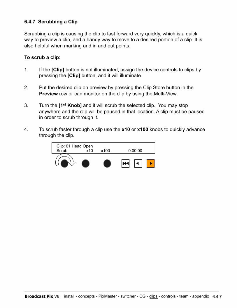
install - concepts - PixMaster - switcher - CG - clips - controls - team - appendix Broadcast Pix V8
6.4.7 Scrubbing a Clip
Scrubbing a clip is causing the clip to fast forward very quickly, which is a quick way to preview a clip, and a handy way to move to a desired portion of a clip. It is also helpful when marking and in and out points.
To scrub a clip:
6.4.7
1. If the [Clip] button is not illuminated, assign the device controls to clips by pressing the [Clip] button, and it will illuminate.
2. Put the desired clip on preview by pressing the Clip Store button in the Preview row or can monitor on the clip by using the Multi-View.
3. Turn the [1st Knob] and it will scrub the selected clip. You may stop anywhere and the clip will be paused in that location. A clip must be paused in order to scrub through it.
4. To scrub faster through a clip use the x10 or x100 knobs to quickly advance through the clip.
Clip: 01 Head Open Scrub x10 x100 0:00:00
install - concepts - PixMaster - switcher - CG - clips - controls - team - appendix Broadcast Pix V8 6.5
6.5 Compressed Clips
The internal clip store of the Slate G Series system can support playback of standard definition and high definition compressed clips. Non-G Series system can only support standard definition clips. This is ideal if you are exporting video files from a non-linear editing system like Avid or Final Cut Pro or even an animated background from Adobe After Effects or Apple Motion. Alpha channels with compressed clips are not supported, to import an animation with an alpha channel you need to export it as a 32 bit image sequence, see section 5.4.4.
To play compressed clips, appropriate codecs need to be installed on the workstation. These are either installed at the factory on new systems, or are installed through an update for existing customers. For assistance please contact technical support.
To play compressed clips:
1. Export your files out of your 3rd party software with these settings:
Standard Definition - File Size: 720x486/NTSC or 720x576/PAL
(4:3 or anamorphic/widescreen at 1.2 pixel aspect ratio 16:9) - Frame Rate: 29.97/NTSC or 25/PAL
- Field Order/Dominance: Bottom/Lower first/NTSC or Top/Upper first/PAL - Scan Mode: Interlaced
High Definition - File Size: 1280x720p or 1920x1080i - Frame Rate: 59.94/50 or 29.97/25
For QuickTime movies: - Video Compression Settings: DV/DVCPro 25 Mbps, H.264 or ProRes
- Quality: Best - Audio Settings: Stereo PCM Data, 16 bit, 48kHz (or any sample rate) - File Extension: .mov
2. Copy the movie file to the D:\clips directory of the Broadcast Pix workstation.
3. Add the file to your show using PixMaster as described in section 3.
4. Play/control your clip as described in this section.
NOTE: The clip store does not support 1080 progressive formats.
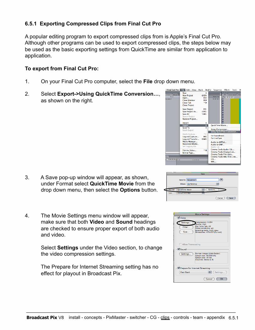
install - concepts - PixMaster - switcher - CG - clips - controls - team - appendix Broadcast Pix V8 6.5.1
6.5.1 Exporting Compressed Clips from Final Cut Pro
A popular editing program to export compressed clips from is Apple’s Final Cut Pro. Although other programs can be used to export compressed clips, the steps below may be used as the basic exporting settings from QuickTime are similar from application to application.
To export from Final Cut Pro:
1. On your Final Cut Pro computer, select the File drop down menu.
2. Select Export->Using QuickTime Conversion…, as shown on the right.
3. A Save pop-up window will appear, as shown, under Format select QuickTime Movie from the drop down menu, then select the Options button.
4. The Movie Settings menu window will appear, make sure that both Video and Sound headings are checked to ensure proper export of both audio and video.
Select Settings under the Video section, to change the video compression settings.
The Prepare for Internet Streaming setting has no effect for playout in Broadcast Pix.
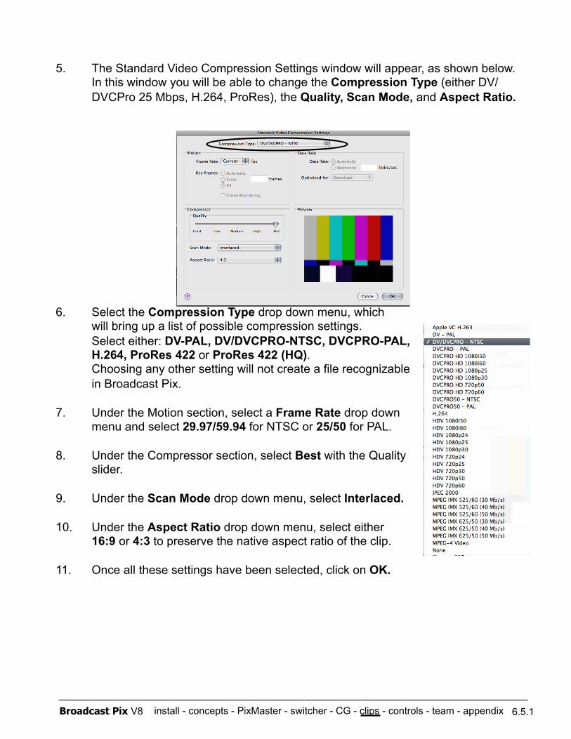
install - concepts - PixMaster - switcher - CG - clips - controls - team - appendix Broadcast Pix V8 6.5.1
5. The Standard Video Compression Settings window will appear, as shown below. In this window you will be able to change the Compression Type (either DV/DVCPro 25 Mbps, H.264, ProRes), the Quality, Scan Mode, and Aspect Ratio.
6. Select the Compression Type drop down menu, which will bring up a list of possible compression settings. Select either: DV-PAL, DV/DVCPRO-NTSC, DVCPRO-PAL, H.264, ProRes 422 or ProRes 422 (HQ). Choosing any other setting will not create a file recognizable in Broadcast Pix.
7. Under the Motion section, select a Frame Rate drop down menu and select 29.97/59.94 for NTSC or 25/50 for PAL.
8. Under the Compressor section, select Best with the Quality slider.
9. Under the Scan Mode drop down menu, select Interlaced.
10. Under the Aspect Ratio drop down menu, select either 16:9 or 4:3 to preserve the native aspect ratio of the clip.
11. Once all these settings have been selected, click on OK.
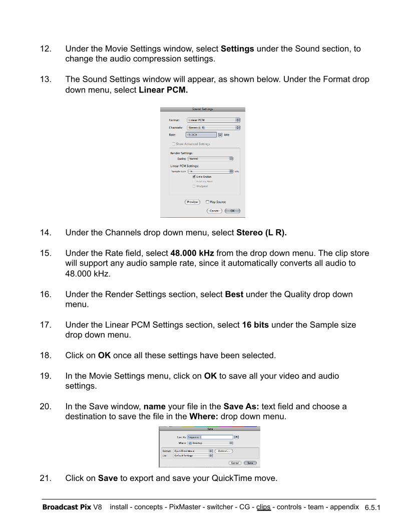
install - concepts - PixMaster - switcher - CG - clips - controls - team - appendix Broadcast Pix V8 6.5.1
12. Under the Movie Settings window, select Settings under the Sound section, to change the audio compression settings.
13. The Sound Settings window will appear, as shown below. Under the Format drop down menu, select Linear PCM.
14. Under the Channels drop down menu, select Stereo (L R).
15. Under the Rate field, select 48.000 kHz from the drop down menu. The clip store will support any audio sample rate, since it automatically converts all audio to 48.000 kHz.
16. Under the Render Settings section, select Best under the Quality drop down menu.
17. Under the Linear PCM Settings section, select 16 bits under the Sample size drop down menu.
18. Click on OK once all these settings have been selected.
19. In the Movie Settings menu, click on OK to save all your video and audio settings.
20. In the Save window, name your file in the Save As: text field and choose a destination to save the file in the Where: drop down menu.
21. Click on Save to export and save your QuickTime move.
install - concepts - PixMaster - switcher - CG - clips - controls - team - appendix Broadcast Pix V8
6.6 Optional Dual Clip Store (Dual DDR)
A second channel of clip store can be installed as an option, and is included on the Slate 2100G and 3000G. It includes a second media hard drive that is striped to the first hard drive. This creates a higher performance media drive that has about twice the capacity of the standard system.
When the second channel of clip store is installed, two clip stores may be defined in a show, just like a second channel of still store can be defined on any system. The second channel of clip store will be accessible like the 2nd channel of CG and Stills by selecting the [Shift] button then the Device Select button.
Clips are recorded onto the second Clip Store channel as they are for the first channel, except that there is a separate thumbnail capture command for the second channel of clip store.
6.6
NOTE: Even though you may have one clip in both channels of the clip store, any control changes (Mark In/Out, Loop, etc) made on one channel with automatically occur on the other clip channel.
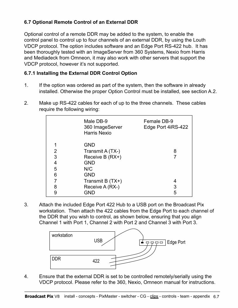
install - concepts - PixMaster - switcher - CG - clips - controls - team - appendix Broadcast Pix V8
6.7 Optional Remote Control of an External DDR
Optional control of a remote DDR may be added to the system, to enable the control panel to control up to four channels of an external DDR, by using the Louth VDCP protocol. The option includes software and an Edge Port RS-422 hub. It has been thoroughly tested with an ImageServer from 360 Systems, Nexio from Harris and Mediadeck from Omneon, it may also work with other servers that support the VDCP protocol, however it’s not supported.
6.7
6.7.1 Installing the External DDR Control Option
1. If the option was ordered as part of the system, then the software in already installed. Otherwise the proper Option Control must be installed, see section A.2.
2. Make up RS-422 cables for each of up to the three channels. These cables require the following wiring:
Male DB-9 Female DB-9 360 ImageServer Edge Port 4iRS-422
Harris Nexio
1 GND 2 Transmit A (TX-) 8 3 Receive B (RX+) 7 4 GND 5 N/C 6 GND 7 Transmit B (TX+) 4 8 Receive A (RX-) 3 9 GND 5
3. Attach the included Edge Port 422 Hub to a USB port on the Broadcast Pix workstation. Then attach the 422 cables from the Edge Port to each channel of the DDR that you wish to control, as shown below, ensuring that you align Channel 1 with Port 1, Channel 2 with Port 2 and Channel 3 with Port 3.
4. Ensure that the external DDR is set to be controlled remotely/serially using the VDCP protocol. Please refer to the 360, Nexio, Omneon manual for instructions.
workstation
DDR
Edge Port USB
422
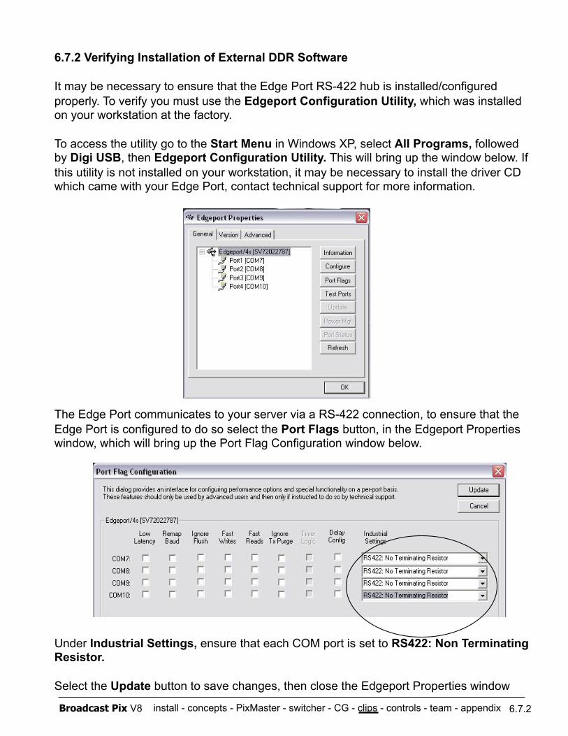
install - concepts - PixMaster - switcher - CG - clips - controls - team - appendix Broadcast Pix V8
6.7.2 Verifying Installation of External DDR Software
It may be necessary to ensure that the Edge Port RS-422 hub is installed/configured properly. To verify you must use the Edgeport Configuration Utility, which was installed on your workstation at the factory.
To access the utility go to the Start Menu in Windows XP, select All Programs, followed by Digi USB, then Edgeport Configuration Utility. This will bring up the window below. If this utility is not installed on your workstation, it may be necessary to install the driver CD which came with your Edge Port, contact technical support for more information.
The Edge Port communicates to your server via a RS-422 connection, to ensure that the Edge Port is configured to do so select the Port Flags button, in the Edgeport Properties window, which will bring up the Port Flag Configuration window below.
Under Industrial Settings, ensure that each COM port is set to RS422: Non Terminating Resistor.
Select the Update button to save changes, then close the Edgeport Properties window
6.7.2
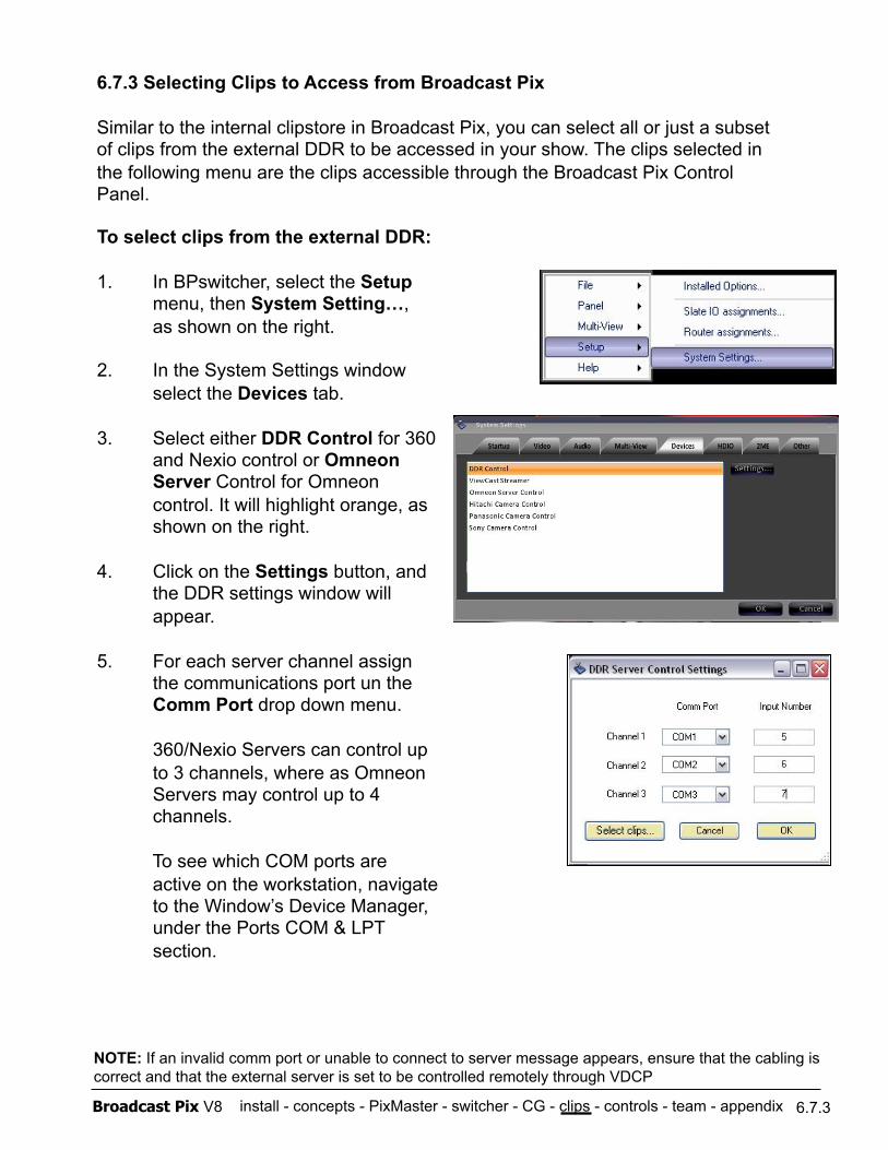
install - concepts - PixMaster - switcher - CG - clips - controls - team - appendix Broadcast Pix V8
6.7.3 Selecting Clips to Access from Broadcast Pix
Similar to the internal clipstore in Broadcast Pix, you can select all or just a subset of clips from the external DDR to be accessed in your show. The clips selected in the following menu are the clips accessible through the Broadcast Pix Control Panel.
6.7.3
To select clips from the external DDR:
1. In BPswitcher, select the Setup menu, then System Setting…, as shown on the right.
2. In the System Settings window select the Devices tab.
3. Select either DDR Control for 360 and Nexio control or Omneon Server Control for Omneon control. It will highlight orange, as shown on the right.
4. Click on the Settings button, and the DDR settings window will appear.
5. For each server channel assign the communications port un the Comm Port drop down menu.
360/Nexio Servers can control up to 3 channels, where as Omneon Servers may control up to 4 channels.
To see which COM ports are active on the workstation, navigate to the Window’s Device Manager, under the Ports COM & LPT section.
NOTE: If an invalid comm port or unable to connect to server message appears, ensure that the cabling is correct and that the external server is set to be controlled remotely through VDCP
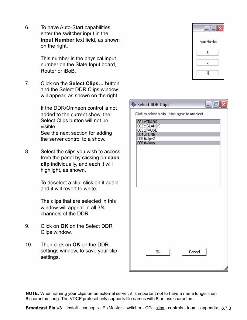
install - concepts - PixMaster - switcher - CG - clips - controls - team - appendix Broadcast Pix V8 6.7.3
6. To have Auto-Start capabilities, enter the switcher input in the Input Number text field, as shown on the right.
This number is the physical input number on the Slate Input board, Router or iBoB.
7. Click on the Select Clips… button and the Select DDR Clips window will appear, as shown on the right.
If the DDR/Omneon control is not added to the current show, the Select Clips button will not be visible. See the next section for adding the server control to a show.
8. Select the clips you wish to access from the panel by clicking on each clip individually, and each it will highlight, as shown.
To deselect a clip, click on it again and it will revert to white.
The clips that are selected in this window will appear in all 3/4 channels of the DDR.
9. Click on OK on the Select DDR Clips window.
10 Then click on OK on the DDR settings window, to save your clip settings.
NOTE: When naming your clips on an external server, it is important not to have a name longer than 8 characters long. The VDCP protocol only supports file names with 8 or less characters.
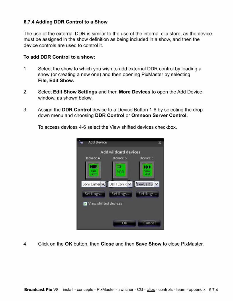
install - concepts - PixMaster - switcher - CG - clips - controls - team - appendix Broadcast Pix V8
To add DDR Control to a show:
1. Select the show to which you wish to add external DDR control by loading a show (or creating a new one) and then opening PixMaster by selecting File, Edit Show.
2. Select Edit Show Settings and then More Devices to open the Add Device window, as shown below.
3. Assign the DDR Control device to a Device Button 1-6 by selecting the drop down menu and choosing DDR Control or Omneon Server Control.
To access devices 4-6 select the View shifted devices checkbox.
4. Click on the OK button, then Close and then Save Show to close PixMaster.
6.7.4
6.7.4 Adding DDR Control to a Show
The use of the external DDR is similar to the use of the internal clip store, as the device must be assigned in the show definition as being included in a show, and then the device controls are used to control it.
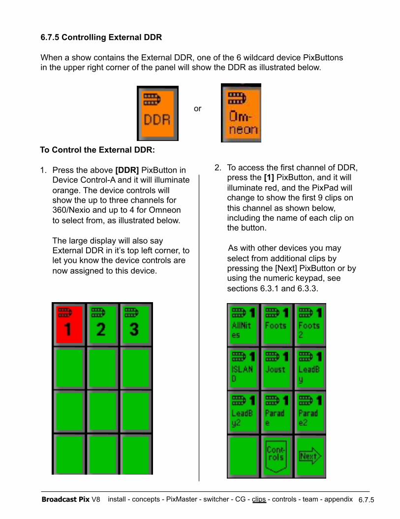
install - concepts - PixMaster - switcher - CG - clips - controls - team - appendix Broadcast Pix V8
6.7.5 Controlling External DDR
When a show contains the External DDR, one of the 6 wildcard device PixButtons in the upper right corner of the panel will show the DDR as illustrated below.
6.7.5
To Control the External DDR:
1. Press the above [DDR] PixButton in Device Control-A and it will illuminate orange. The device controls will show the up to three channels for 360/Nexio and up to 4 for Omneon to select from, as illustrated below.
The large display will also say External DDR in it’s top left corner, to let you know the device controls are now assigned to this device.
2. To access the first channel of DDR, press the [1] PixButton, and it will illuminate red, and the PixPad will change to show the first 9 clips on this channel as shown below, including the name of each clip on the button.
As with other devices you may select from additional clips by pressing the [Next] PixButton or by using the numeric keypad, see sections 6.3.1 and 6.3.3.
or
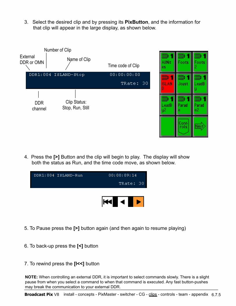
install - concepts - PixMaster - switcher - CG - clips - controls - team - appendix Broadcast Pix V8
4. Press the [>] Button and the clip will begin to play. The display will show both the status as Run, and the time code move, as shown below.
5. To Pause press the [>] button again (and then again to resume playing)
6. To back-up press the [<] button
7. To rewind press the [I<<] button
3. Select the desired clip and by pressing its PixButton, and the information for that clip will appear in the large display, as shown below.
6.7.5
Name of Clip Time code of Clip
External DDR or OMN
Clip Status: Stop, Run, Still
DDR channel
Number of Clip
NOTE: When controlling an external DDR, it is important to select commands slowly. There is a slight pause from when you select a command to when that command is executed. Any fast button-pushes may break the communication to your external DDR.
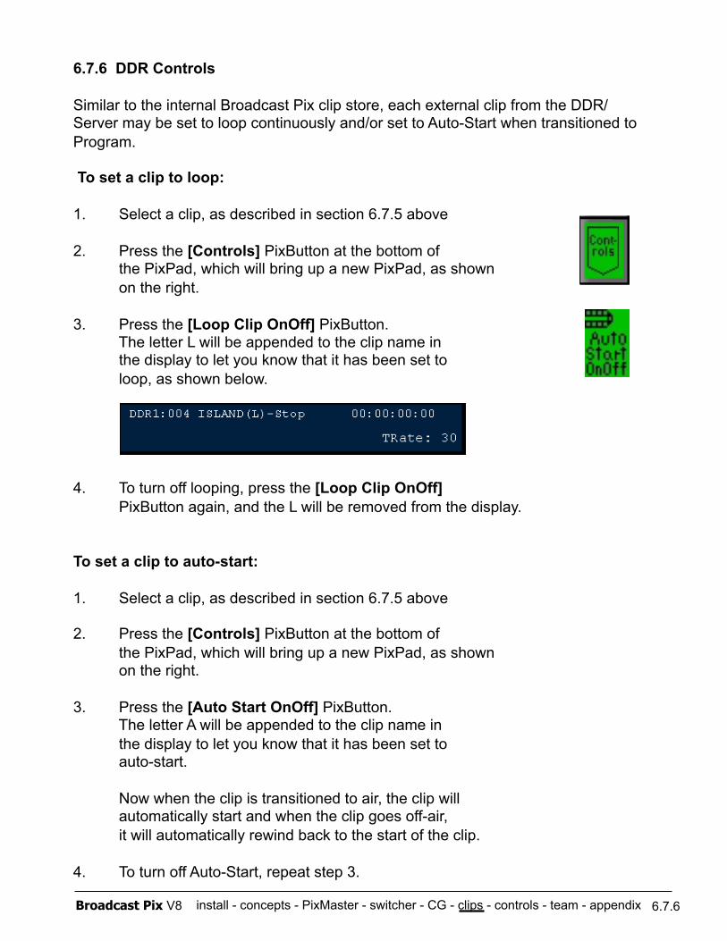
install - concepts - PixMaster - switcher - CG - clips - controls - team - appendix Broadcast Pix V8 6.7.6
6.7.6 DDR Controls
Similar to the internal Broadcast Pix clip store, each external clip from the DDR/ Server may be set to loop continuously and/or set to Auto-Start when transitioned to Program.
To set a clip to loop:
1. Select a clip, as described in section 6.7.5 above
2. Press the [Controls] PixButton at the bottom of the PixPad, which will bring up a new PixPad, as shown on the right.
3. Press the [Loop Clip OnOff] PixButton. The letter L will be appended to the clip name in the display to let you know that it has been set to loop, as shown below.
4. To turn off looping, press the [Loop Clip OnOff] PixButton again, and the L will be removed from the display.
To set a clip to auto-start:
1. Select a clip, as described in section 6.7.5 above
2. Press the [Controls] PixButton at the bottom of the PixPad, which will bring up a new PixPad, as shown on the right.
3. Press the [Auto Start OnOff] PixButton. The letter A will be appended to the clip name in the display to let you know that it has been set to auto-start.
Now when the clip is transitioned to air, the clip will automatically start and when the clip goes off-air, it will automatically rewind back to the start of the clip.
4. To turn off Auto-Start, repeat step 3.
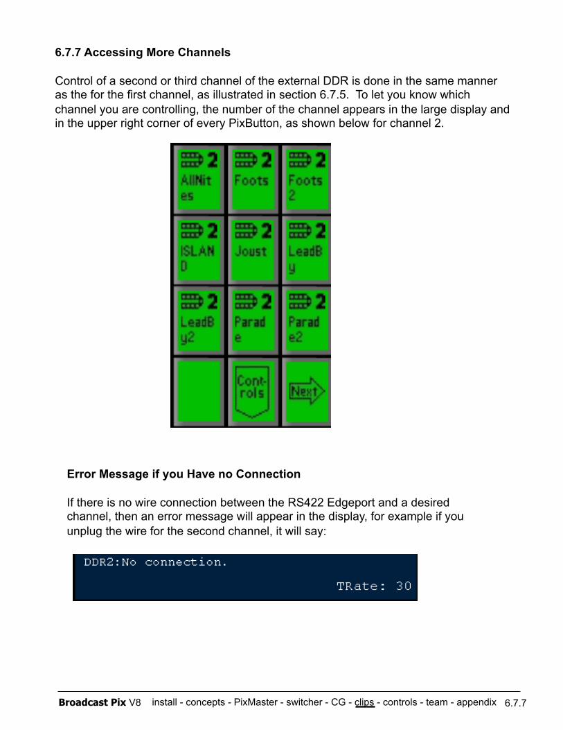
install - concepts - PixMaster - switcher - CG - clips - controls - team - appendix Broadcast Pix V8 6.7.7
6.7.7 Accessing More Channels
Control of a second or third channel of the external DDR is done in the same manner as the for the first channel, as illustrated in section 6.7.5. To let you know which channel you are controlling, the number of the channel appears in the large display and in the upper right corner of every PixButton, as shown below for channel 2.
Error Message if you Have no Connection
If there is no wire connection between the RS422 Edgeport and a desired channel, then an error message will appear in the display, for example if you unplug the wire for the second channel, it will say:
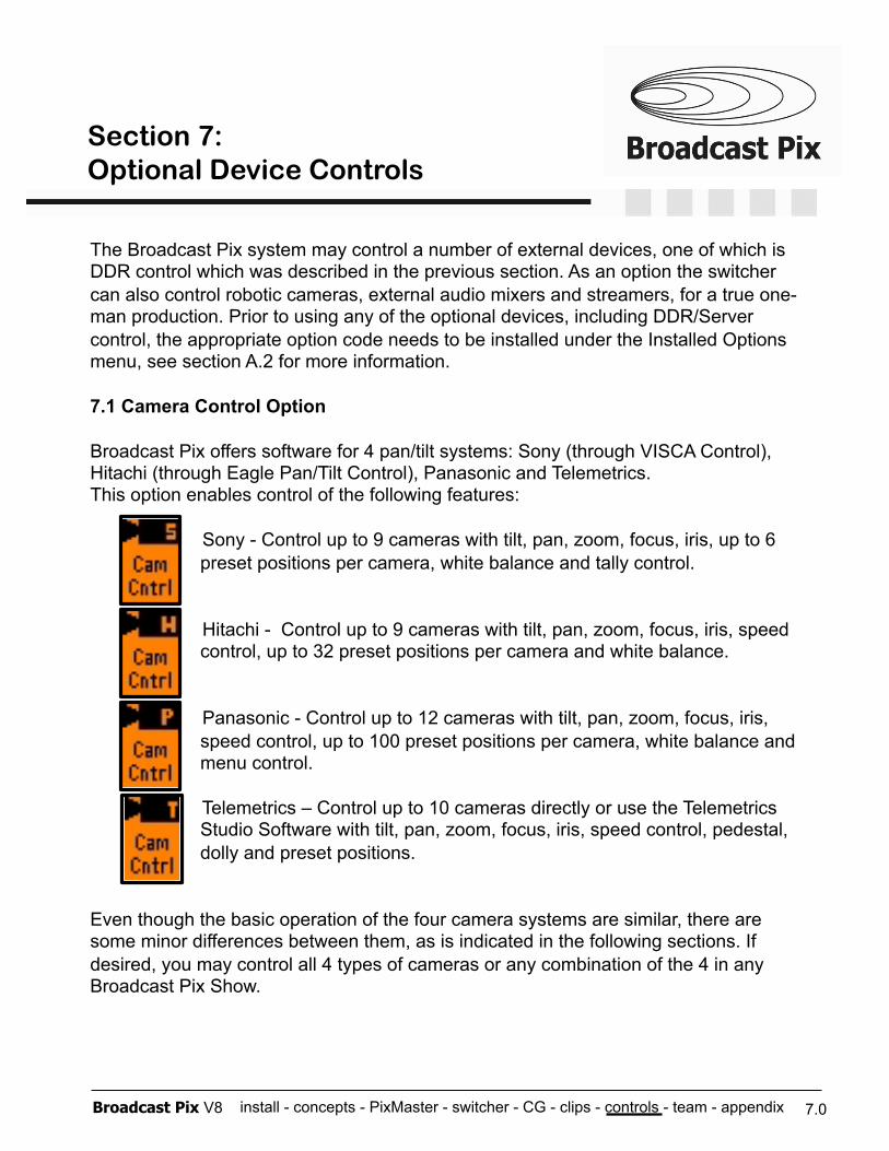
install - concepts - PixMaster - switcher - CG - clips - controls - team - appendix Broadcast Pix V8
The Broadcast Pix system may control a number of external devices, one of which is DDR control which was described in the previous section. As an option the switcher can also control robotic cameras, external audio mixers and streamers, for a true one-man production. Prior to using any of the optional devices, including DDR/Server control, the appropriate option code needs to be installed under the Installed Options menu, see section A.2 for more information.
7.1 Camera Control Option
Broadcast Pix offers software for 4 pan/tilt systems: Sony (through VISCA Control), Hitachi (through Eagle Pan/Tilt Control), Panasonic and Telemetrics. This option enables control of the following features:
Sony - Control up to 9 cameras with tilt, pan, zoom, focus, iris, up to 6 preset positions per camera, white balance and tally control.
Hitachi - Control up to 9 cameras with tilt, pan, zoom, focus, iris, speed control, up to 32 preset positions per camera and white balance.
Panasonic - Control up to 12 cameras with tilt, pan, zoom, focus, iris, speed control, up to 100 preset positions per camera, white balance and menu control.
Telemetrics – Control up to 10 cameras directly or use the Telemetrics Studio Software with tilt, pan, zoom, focus, iris, speed control, pedestal, dolly and preset positions.
Even though the basic operation of the four camera systems are similar, there are some minor differences between them, as is indicated in the following sections. If desired, you may control all 4 types of cameras or any combination of the 4 in any Broadcast Pix Show.
7.0
Section 7: Optional Device Controls
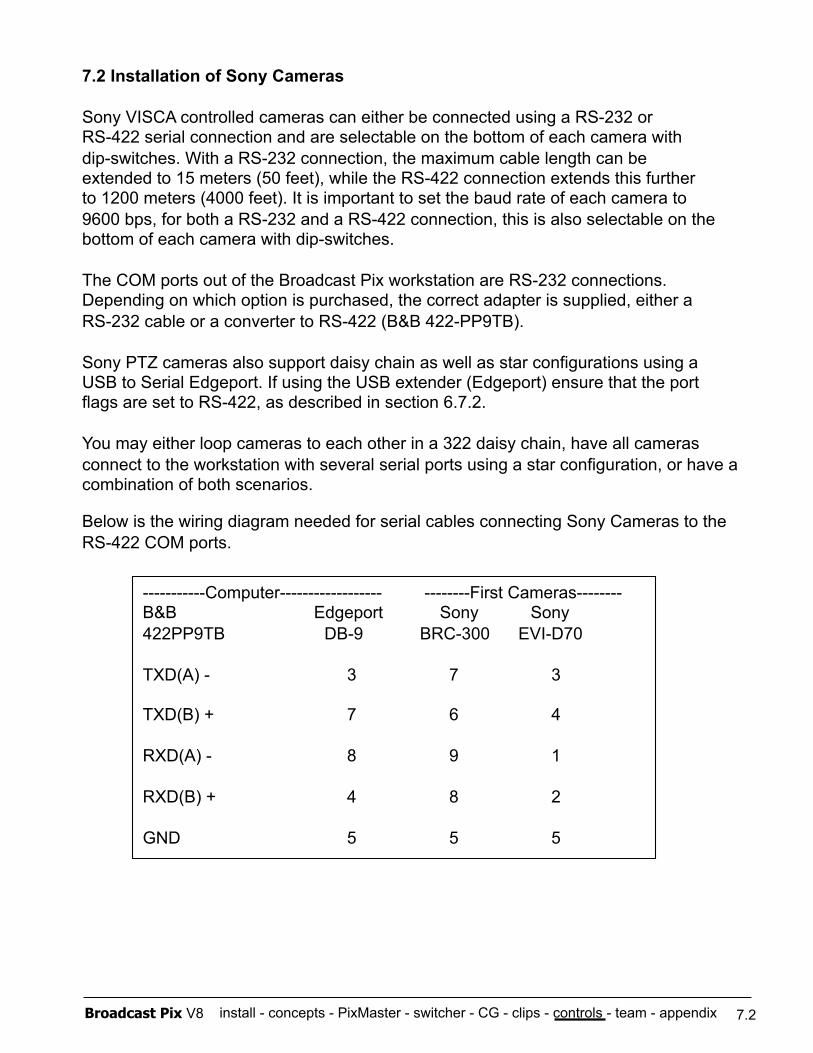
install - concepts - PixMaster - switcher - CG - clips - controls - team - appendix Broadcast Pix V8
7.2 Installation of Sony Cameras
Sony VISCA controlled cameras can either be connected using a RS-232 or RS-422 serial connection and are selectable on the bottom of each camera with dip-switches. With a RS-232 connection, the maximum cable length can be extended to 15 meters (50 feet), while the RS-422 connection extends this further to 1200 meters (4000 feet). It is important to set the baud rate of each camera to 9600 bps, for both a RS-232 and a RS-422 connection, this is also selectable on the bottom of each camera with dip-switches.
The COM ports out of the Broadcast Pix workstation are RS-232 connections. Depending on which option is purchased, the correct adapter is supplied, either a RS-232 cable or a converter to RS-422 (B&B 422-PP9TB).
Sony PTZ cameras also support daisy chain as well as star configurations using a USB to Serial Edgeport. If using the USB extender (Edgeport) ensure that the port flags are set to RS-422, as described in section 6.7.2.
You may either loop cameras to each other in a 322 daisy chain, have all cameras connect to the workstation with several serial ports using a star configuration, or have a combination of both scenarios.
Below is the wiring diagram needed for serial cables connecting Sony Cameras to the RS-422 COM ports.
7.2
-----------Computer------------------ --------First Cameras-------- B&B Edgeport Sony Sony 422PP9TB DB-9 BRC-300 EVI-D70
TXD(A) - 3 7 3
TXD(B) + 7 6 4
RXD(A) - 8 9 1
RXD(B) + 4 8 2
GND 5 5 5
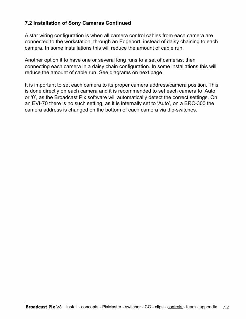
install - concepts - PixMaster - switcher - CG - clips - controls - team - appendix Broadcast Pix V8
7.2 Installation of Sony Cameras Continued
A star wiring configuration is when all camera control cables from each camera are connected to the workstation, through an Edgeport, instead of daisy chaining to each camera. In some installations this will reduce the amount of cable run.
Another option it to have one or several long runs to a set of cameras, then connecting each camera in a daisy chain configuration. In some installations this will reduce the amount of cable run. See diagrams on next page.
It is important to set each camera to its proper camera address/camera position. This is done directly on each camera and it is recommended to set each camera to ‘Auto’ or ‘0’, as the Broadcast Pix software will automatically detect the correct settings. On an EVI-70 there is no such setting, as it is internally set to ‘Auto’, on a BRC-300 the camera address is changed on the bottom of each camera via dip-switches.
7.2
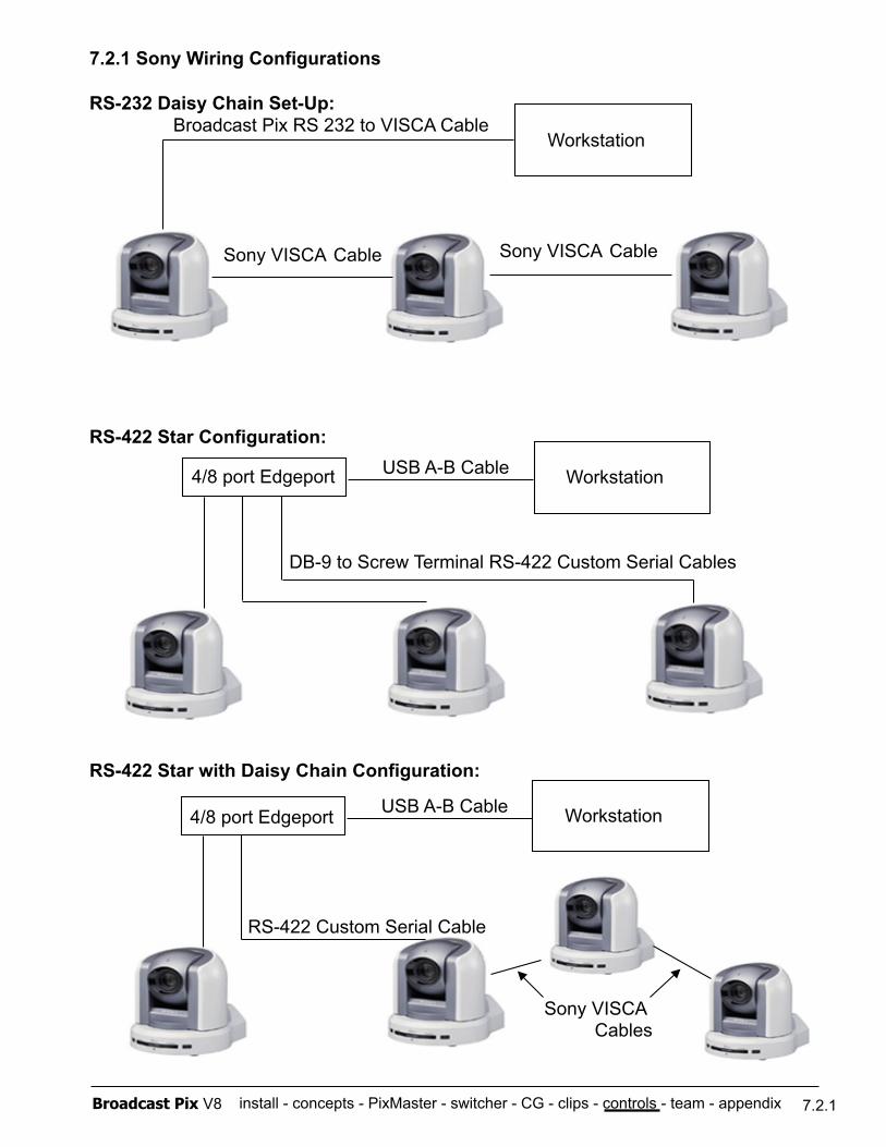
install - concepts - PixMaster - switcher - CG - clips - controls - team - appendix Broadcast Pix V8
7.2.1 Sony Wiring Configurations
RS-232 Daisy Chain Set-Up:
RS-422 Star Configuration:
RS-422 Star with Daisy Chain Configuration:
7.2.1
Sony VISCA Cable Sony VISCA Cable
Broadcast Pix RS 232 to VISCA Cable Workstation
Workstation 4/8 port Edgeport USB A-B Cable
DB-9 to Screw Terminal RS-422 Custom Serial Cables
Workstation 4/8 port Edgeport USB A-B Cable
RS-422 Custom Serial Cable
Sony VISCA Cables
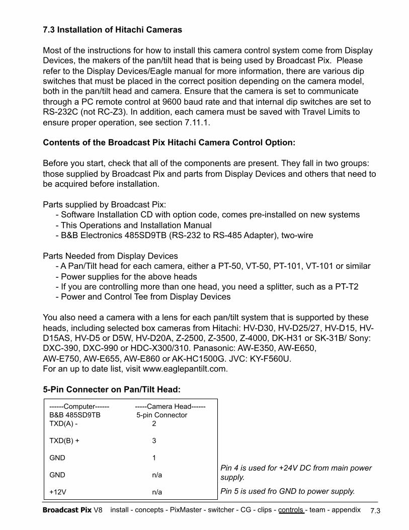
install - concepts - PixMaster - switcher - CG - clips - controls - team - appendix Broadcast Pix V8
7.3 Installation of Hitachi Cameras
Most of the instructions for how to install this camera control system come from Display Devices, the makers of the pan/tilt head that is being used by Broadcast Pix. Please refer to the Display Devices/Eagle manual for more information, there are various dip switches that must be placed in the correct position depending on the camera model, both in the pan/tilt head and camera. Ensure that the camera is set to communicate through a PC remote control at 9600 baud rate and that internal dip switches are set to RS-232C (not RC-Z3). In addition, each camera must be saved with Travel Limits to ensure proper operation, see section 7.11.1.
Contents of the Broadcast Pix Hitachi Camera Control Option:
Before you start, check that all of the components are present. They fall in two groups: those supplied by Broadcast Pix and parts from Display Devices and others that need to be acquired before installation.
Parts supplied by Broadcast Pix: - Software Installation CD with option code, comes pre-installed on new systems - This Operations and Installation Manual - B&B Electronics 485SD9TB (RS-232 to RS-485 Adapter), two-wire
Parts Needed from Display Devices - A Pan/Tilt head for each camera, either a PT-50, VT-50, PT-101, VT-101 or similar - Power supplies for the above heads - If you are controlling more than one head, you need a splitter, such as a PT-T2 - Power and Control Tee from Display Devices
You also need a camera with a lens for each pan/tilt system that is supported by these heads, including selected box cameras from Hitachi: HV-D30, HV-D25/27, HV-D15, HV-D15AS, HV-D5 or D5W, HV-D20A, Z-2500, Z-3500, Z-4000, DK-H31 or SK-31B/ Sony: DXC-390, DXC-990 or HDC-X300/310. Panasonic: AW-E350, AW-E650, AW-E750, AW-E655, AW-E860 or AK-HC1500G. JVC: KY-F560U. For an up to date list, visit www.eaglepantilt.com.
5-Pin Connecter on Pan/Tilt Head:
7.3
------Computer------ -----Camera Head------ B&B 485SD9TB 5-pin Connector TXD(A) - 2
TXD(B) + 3
GND 1
GND n/a
+12V n/a
Pin 4 is used for +24V DC from main power supply.
Pin 5 is used fro GND to power supply.
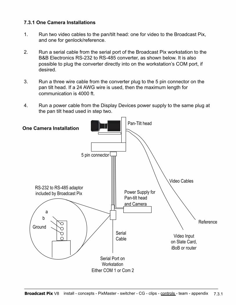
install - concepts - PixMaster - switcher - CG - clips - controls - team - appendix Broadcast Pix V8
7.3.1 One Camera Installations
1. Run two video cables to the pan/tilt head: one for video to the Broadcast Pix, and one for genlock/reference.
2. Run a serial cable from the serial port of the Broadcast Pix workstation to the B&B Electronics RS-232 to RS-485 converter, as shown below. It is also possible to plug the converter directly into on the workstation’s COM port, if desired.
3. Run a three wire cable from the converter plug to the 5 pin connector on the pan tilt head. If a 24 AWG wire is used, then the maximum length for communication is 4000 ft.
4. Run a power cable from the Display Devices power supply to the same plug at the pan tilt head used in step two.
Serial Port on Workstation
Either COM 1 or Com 2
Power Supply for Pan-tilt head and Camera
Serial Cable
Pan-Tilt head
Video Cables
Video Input on Slate Card, iBoB or router
Reference
One Camera Installation
Ground
a b
RS-232 to RS-485 adaptor included by Broadcast Pix
7.3.1
5 pin connector
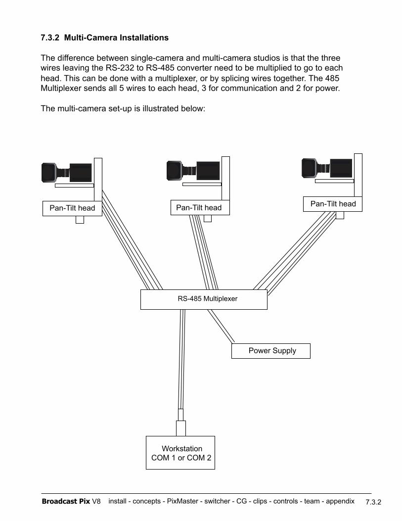
install - concepts - PixMaster - switcher - CG - clips - controls - team - appendix Broadcast Pix V8
7.3.2 Multi-Camera Installations
The difference between single-camera and multi-camera studios is that the three wires leaving the RS-232 to RS-485 converter need to be multiplied to go to each head. This can be done with a multiplexer, or by splicing wires together. The 485 Multiplexer sends all 5 wires to each head, 3 for communication and 2 for power.
The multi-camera set-up is illustrated below:
7.3.2
Workstation COM 1 or COM 2
Power Supply
RS-485 Multiplexer
Pan-Tilt head Pan-Tilt head Pan-Tilt head
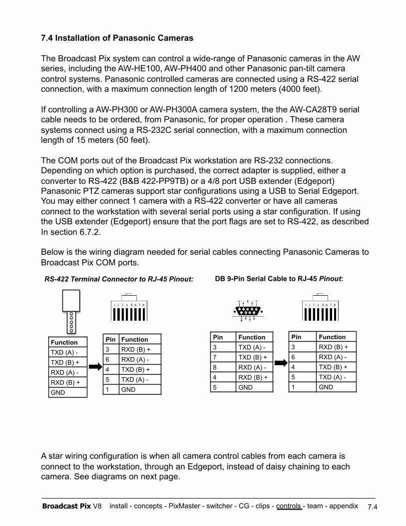
install - concepts - PixMaster - switcher - CG - clips - controls - team - appendix Broadcast Pix V8
7.4 Installation of Panasonic Cameras
The Broadcast Pix system can control a wide-range of Panasonic cameras in the AW series, including the AW-HE100, AW-PH400 and other Panasonic pan-tilt camera control systems. Panasonic controlled cameras are connected using a RS-422 serial connection, with a maximum connection length of 1200 meters (4000 feet).
If controlling a AW-PH300 or AW-PH300A camera system, the the AW-CA28T9 serial cable needs to be ordered, from Panasonic, for proper operation . These camera systems connect using a RS-232C serial connection, with a maximum connection length of 15 meters (50 feet).
The COM ports out of the Broadcast Pix workstation are RS-232 connections. Depending on which option is purchased, the correct adapter is supplied, either a converter to RS-422 (B&B 422-PP9TB) or a 4/8 port USB extender (Edgeport) Panasonic PTZ cameras support star configurations using a USB to Serial Edgeport. You may either connect 1 camera with a RS-422 converter or have all cameras connect to the workstation with several serial ports using a star configuration. If using the USB extender (Edgeport) ensure that the port flags are set to RS-422, as described In section 6.7.2.
Below is the wiring diagram needed for serial cables connecting Panasonic Cameras to Broadcast Pix COM ports.
A star wiring configuration is when all camera control cables from each camera is connect to the workstation, through an Edgeport, instead of daisy chaining to each camera. See diagrams on next page.
7.4
Function TXD (A) - TXD (B) + RXD (A) - RXD (B) + GND
Pin Function 3 RXD (B) + 6 RXD (A) - 4 TXD (B) + 5 TXD (A) - 1 GND
RS-422 Terminal Connector to RJ-45 Pinout:
Pin Function 3 TXD (A) - 7 TXD (B) + 8 RXD (A) - 4 RXD (B) + 5 GND
DB 9-Pin Serial Cable to RJ-45 Pinout:
Pin Function 3 RXD (B) + 6 RXD (A) - 4 TXD (B) + 5 TXD (A) - 1 GND
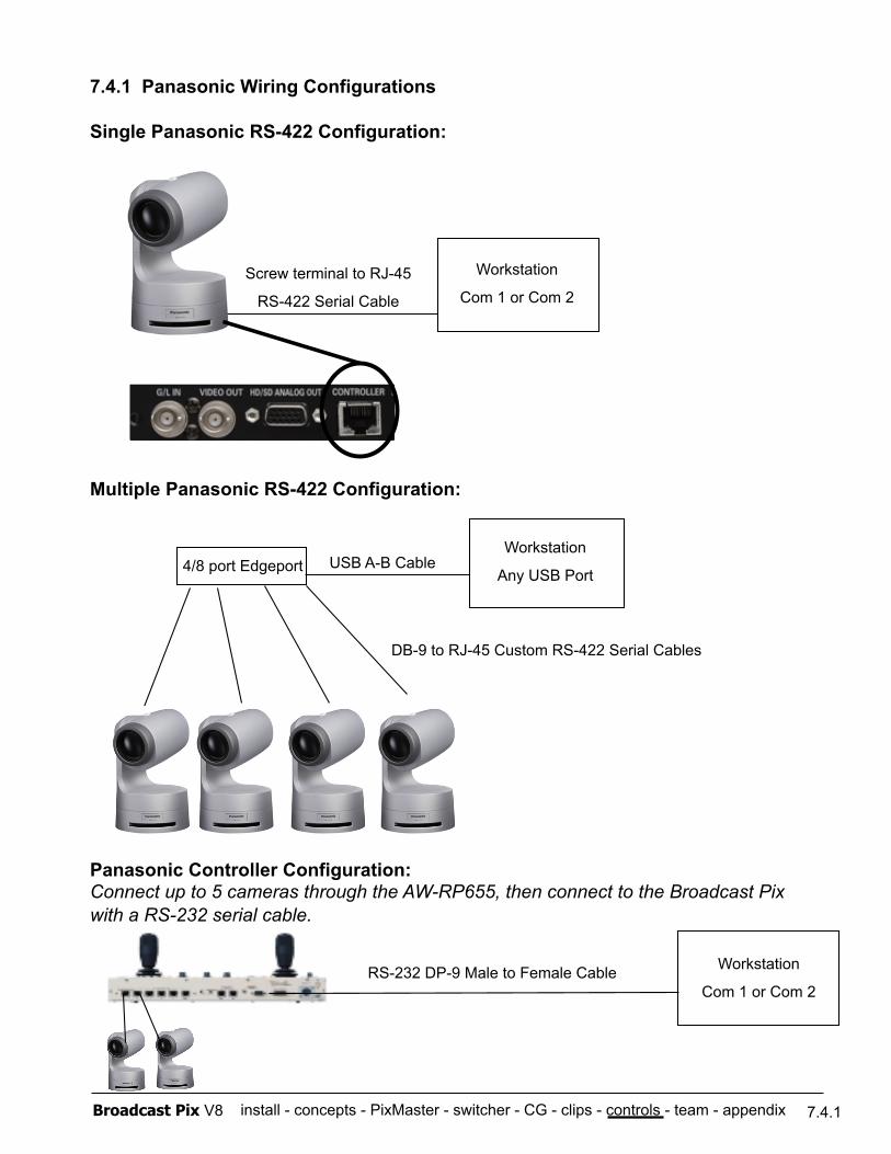
install - concepts - PixMaster - switcher - CG - clips - controls - team - appendix Broadcast Pix V8
7.4.1 Panasonic Wiring Configurations
Single Panasonic RS-422 Configuration:
Multiple Panasonic RS-422 Configuration:
Panasonic Controller Configuration: Connect up to 5 cameras through the AW-RP655, then connect to the Broadcast Pix with a RS-232 serial cable.
7.4.1
Screw terminal to RJ-45
RS-422 Serial Cable
Workstation
Com 1 or Com 2
USB A-B Cable Workstation
Any USB Port 4/8 port Edgeport
DB-9 to RJ-45 Custom RS-422 Serial Cables
Workstation
Com 1 or Com 2 RS-232 DP-9 Male to Female Cable

install - concepts - PixMaster - switcher - CG - clips - controls - team - appendix Broadcast Pix V8
7.5 Installation of Telemetrics Camera Systems
The Broadcast Pix system can control the full line of Telemetrics camera systems, including the PT-CP-S4, Televator and TeleGlide. Broadcast Pix offers basic support for Telemetrics Systems. For detailed wiring information and technical support, contact Telemetrics, Inc. at +1-201-848-9818.
There are 2 main ways to configure a Telemetrics systems with Broadcast Pix control:
- Direct control from the Broadcast Pix to the Telemetrics camera head. This configuration allows for up to 10 cameras to be controlled by Broadcast Pix. No shading/white balance control is offered when controlled directly, camera/lens manufacturers remote panels may be needed for shading. When controlling more than 1 camera, the Telmetrics Serial Transfer Switch, STS-12, is needed to connect multiple serial cables.
- Broadcast Pix control of the camera systems through the Telemetrics Studio Software, CPS-ST-S. This configuration allows for up to 50 cameras to be controlled through the Telemetrics CPS-ST-S software application. Full shading/white balance control is provided by the CPS-ST-S, and not by Broadcast Pix. A single serial cable from the Broadcast Pix workstation to the CPS-ST-S is needed.
The control for both configurations can can either be connected using a RS-232 or RS-422 serial connection and are selectable in the Camera Control Settings menu in BPSwitcher. With a RS-232 connection, the maximum cable length can be extended to 15 meters (50 feet), while the RS-422 connection extends this further to 1200 meters (4000 feet).
The COM ports out of the Broadcast Pix workstation are RS-232 connections.
7.5
Pin Function 2 TXD 3 RXD 5 GND
RS-232 DB 9-Pin Serial Cable Pinout:
Pin Function 3 TXD - 4 RXD + 5 GND 7 TXD + 8 RXD -
RS-422 DB 9-Pin Serial Cable Pinout for Edgeport:
Pin Function 3 RXD - 1 TXD + 5 GND 4 RXD + 2 TXD -
Female (Edgeport end) Male (Telemetrics end)
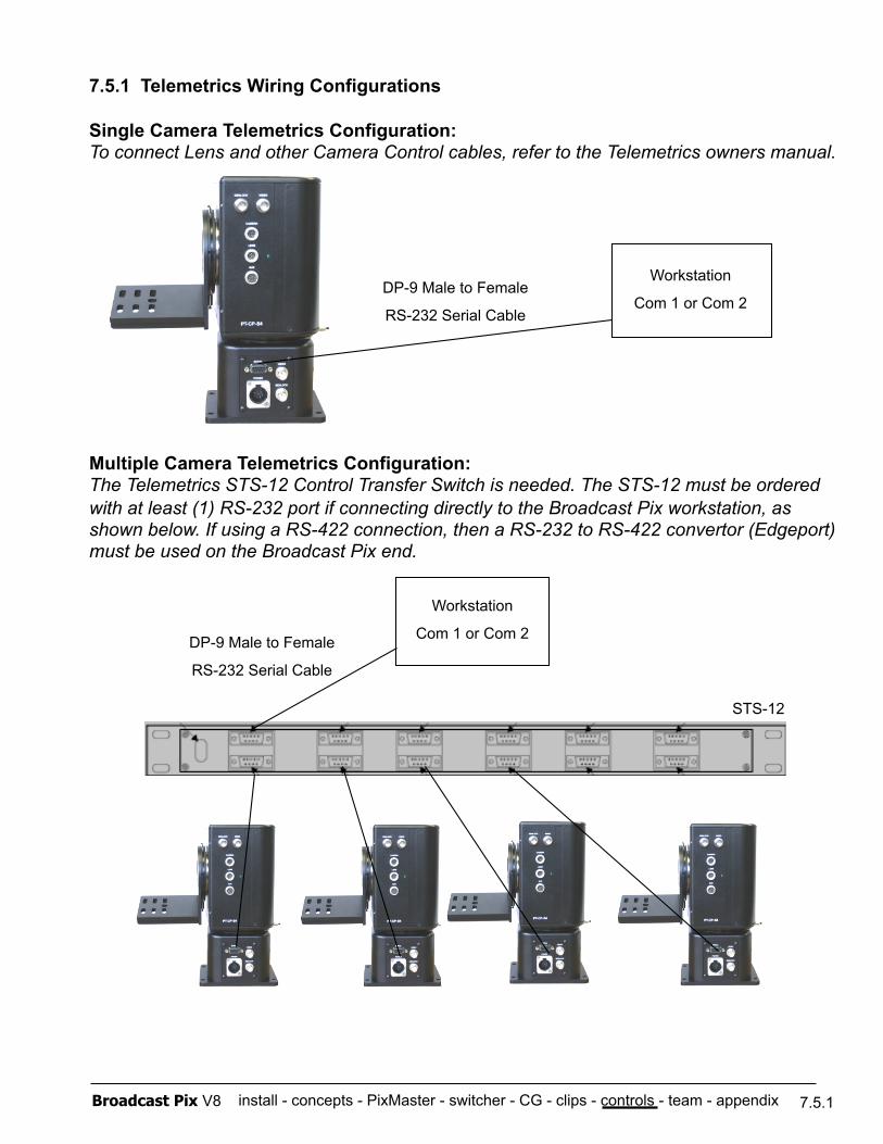
install - concepts - PixMaster - switcher - CG - clips - controls - team - appendix Broadcast Pix V8
7.5.1 Telemetrics Wiring Configurations
Single Camera Telemetrics Configuration: To connect Lens and other Camera Control cables, refer to the Telemetrics owners manual.
Multiple Camera Telemetrics Configuration: The Telemetrics STS-12 Control Transfer Switch is needed. The STS-12 must be ordered with at least (1) RS-232 port if connecting directly to the Broadcast Pix workstation, as shown below. If using a RS-422 connection, then a RS-232 to RS-422 convertor (Edgeport) must be used on the Broadcast Pix end.
7.5.1
DP-9 Male to Female
RS-232 Serial Cable
Workstation
Com 1 or Com 2
STS-12
Workstation
Com 1 or Com 2 DP-9 Male to Female
RS-232 Serial Cable
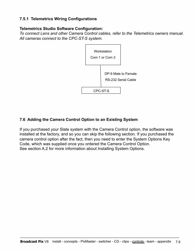
install - concepts - PixMaster - switcher - CG - clips - controls - team - appendix Broadcast Pix V8
7.5.1 Telemetrics Wiring Configurations
Telemetrics Studio Software Configuration: To connect Lens and other Camera Control cables, refer to the Telemetrics owners manual. All cameras connect to the CPC-ST-S system.
7.6
DP-9 Male to Female
RS-232 Serial Cable
Workstation
Com 1 or Com 2
CPC-ST-S
7.6 Adding the Camera Control Option to an Existing System
If you purchased your Slate system with the Camera Control option, the software was installed at the factory, and so you can skip the following section. If you purchased the camera control option after the fact, then you need to enter the System Options Key Code, which was supplied once you ordered the Camera Control Option. See section A.2 for more information about Installing System Options.
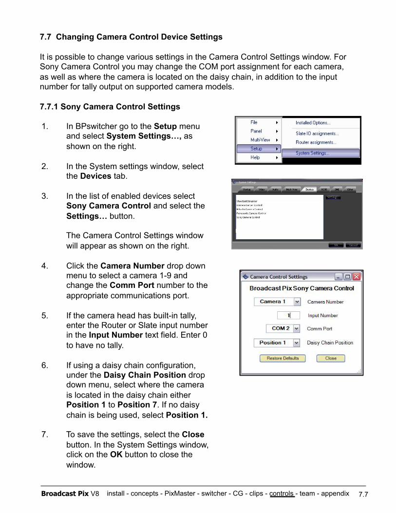
install - concepts - PixMaster - switcher - CG - clips - controls - team - appendix Broadcast Pix V8
7.7 Changing Camera Control Device Settings
It is possible to change various settings in the Camera Control Settings window. For Sony Camera Control you may change the COM port assignment for each camera, as well as where the camera is located on the daisy chain, in addition to the input number for tally output on supported camera models.
7.7.1 Sony Camera Control Settings
7.7
1. In BPswitcher go to the Setup menu and select System Settings…, as shown on the right.
2. In the System settings window, select the Devices tab.
3. In the list of enabled devices select Sony Camera Control and select the Settings… button.
The Camera Control Settings window will appear as shown on the right.
4. Click the Camera Number drop down menu to select a camera 1-9 and change the Comm Port number to the appropriate communications port.
5. If the camera head has built-in tally, enter the Router or Slate input number in the Input Number text field. Enter 0 to have no tally.
6. If using a daisy chain configuration, under the Daisy Chain Position drop down menu, select where the camera is located in the daisy chain either Position 1 to Position 7. If no daisy chain is being used, select Position 1.
7. To save the settings, select the Close button. In the System Settings window, click on the OK button to close the window.
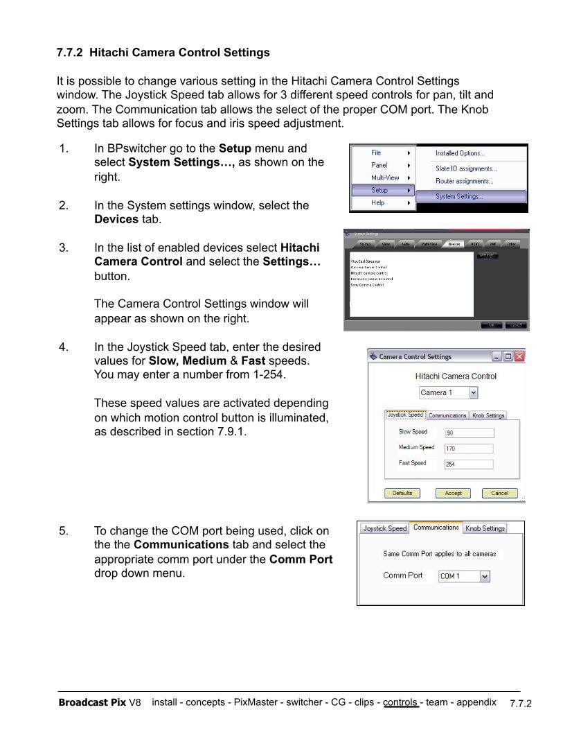
install - concepts - PixMaster - switcher - CG - clips - controls - team - appendix Broadcast Pix V8
7.7.2 Hitachi Camera Control Settings
It is possible to change various setting in the Hitachi Camera Control Settings window. The Joystick Speed tab allows for 3 different speed controls for pan, tilt and zoom. The Communication tab allows the select of the proper COM port. The Knob Settings tab allows for focus and iris speed adjustment.
7.7.2
1. In BPswitcher go to the Setup menu and select System Settings…, as shown on the right.
2. In the System settings window, select the Devices tab.
3. In the list of enabled devices select Hitachi Camera Control and select the Settings… button.
The Camera Control Settings window will appear as shown on the right.
4. In the Joystick Speed tab, enter the desired values for Slow, Medium & Fast speeds. You may enter a number from 1-254.
These speed values are activated depending on which motion control button is illuminated, as described in section 7.9.1.
5. To change the COM port being used, click on the the Communications tab and select the appropriate comm port under the Comm Port drop down menu.
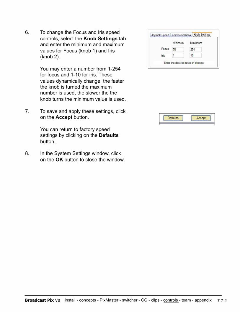
install - concepts - PixMaster - switcher - CG - clips - controls - team - appendix Broadcast Pix V8 7.7.2
6. To change the Focus and Iris speed controls, select the Knob Settings tab and enter the minimum and maximum values for Focus (knob 1) and Iris (knob 2).
You may enter a number from 1-254 for focus and 1-10 for iris. These values dynamically change, the faster the knob is turned the maximum number is used, the slower the the knob turns the minimum value is used.
7. To save and apply these settings, click on the Accept button.
You can return to factory speed settings by clicking on the Defaults button.
8. In the System Settings window, click on the OK button to close the window.
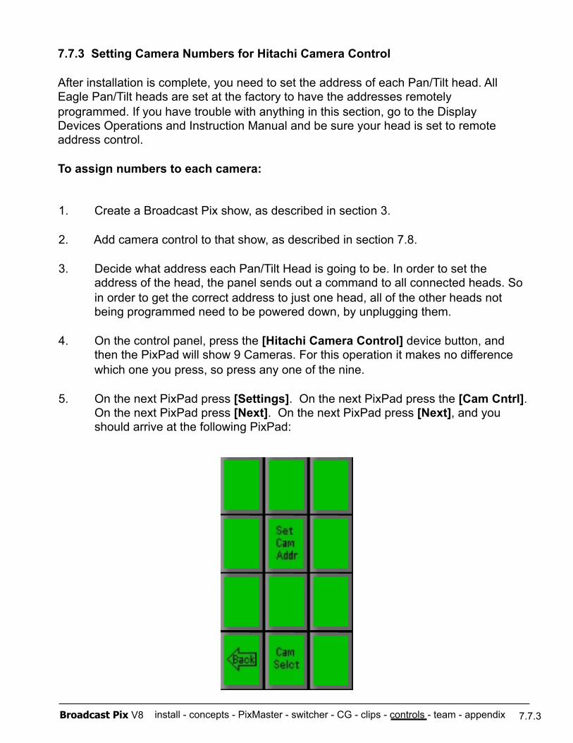
install - concepts - PixMaster - switcher - CG - clips - controls - team - appendix Broadcast Pix V8
7.7.3 Setting Camera Numbers for Hitachi Camera Control
After installation is complete, you need to set the address of each Pan/Tilt head. All Eagle Pan/Tilt heads are set at the factory to have the addresses remotely programmed. If you have trouble with anything in this section, go to the Display Devices Operations and Instruction Manual and be sure your head is set to remote address control.
To assign numbers to each camera:
1. Create a Broadcast Pix show, as described in section 3.
2. Add camera control to that show, as described in section 7.8.
3. Decide what address each Pan/Tilt Head is going to be. In order to set the address of the head, the panel sends out a command to all connected heads. So in order to get the correct address to just one head, all of the other heads not being programmed need to be powered down, by unplugging them.
4. On the control panel, press the [Hitachi Camera Control] device button, and then the PixPad will show 9 Cameras. For this operation it makes no difference which one you press, so press any one of the nine.
5. On the next PixPad press [Settings]. On the next PixPad press the [Cam Cntrl]. On the next PixPad press [Next]. On the next PixPad press [Next], and you should arrive at the following PixPad:
7.7.3
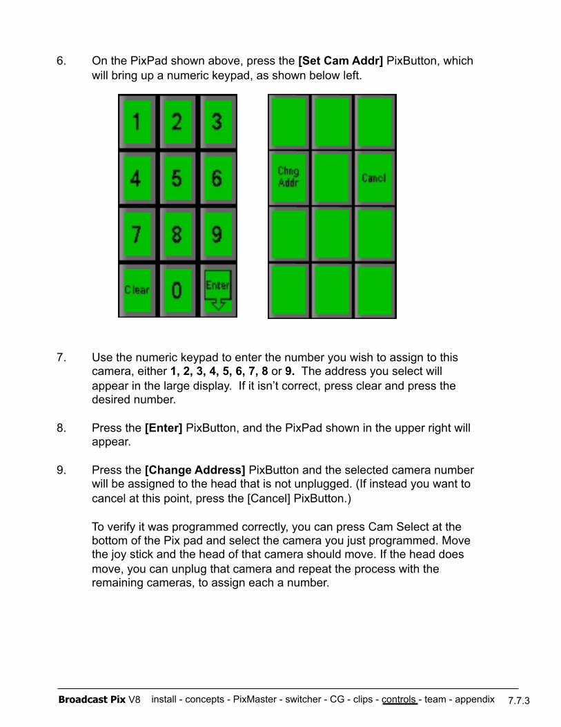
install - concepts - PixMaster - switcher - CG - clips - controls - team - appendix Broadcast Pix V8
6. On the PixPad shown above, press the [Set Cam Addr] PixButton, which will bring up a numeric keypad, as shown below left.
7. Use the numeric keypad to enter the number you wish to assign to this camera, either 1, 2, 3, 4, 5, 6, 7, 8 or 9. The address you select will appear in the large display. If it isn’t correct, press clear and press the desired number.
8. Press the [Enter] PixButton, and the PixPad shown in the upper right will appear.
9. Press the [Change Address] PixButton and the selected camera number will be assigned to the head that is not unplugged. (If instead you want to cancel at this point, press the [Cancel] PixButton.)
To verify it was programmed correctly, you can press Cam Select at the bottom of the Pix pad and select the camera you just programmed. Move the joy stick and the head of that camera should move. If the head does move, you can unplug that camera and repeat the process with the remaining cameras, to assign each a number.
7.7.3
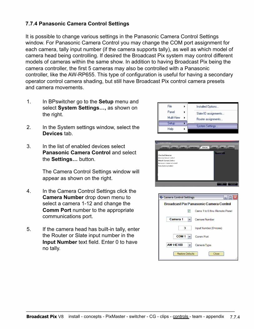
install - concepts - PixMaster - switcher - CG - clips - controls - team - appendix Broadcast Pix V8
7.7.4 Panasonic Camera Control Settings
It is possible to change various settings in the Panasonic Camera Control Settings window. For Panasonic Camera Control you may change the COM port assignment for each camera, tally input number (if the camera supports tally), as well as which model of camera head being controlling. If desired the Broadcast Pix system may control different models of cameras within the same show. In addition to having Broadcast Pix being the camera controller, the first 5 cameras may also be controlled with a Panasonic controller, like the AW-RP655. This type of configuration is useful for having a secondary operator control camera shading, but still have Broadcast Pix control camera presets and camera movements.
7.7.4
1. In BPswitcher go to the Setup menu and select System Settings…, as shown on the right.
2. In the System settings window, select the Devices tab.
3. In the list of enabled devices select Panasonic Camera Control and select the Settings… button.
The Camera Control Settings window will appear as shown on the right.
4. In the Camera Control Settings click the Camera Number drop down menu to select a camera 1-12 and change the Comm Port number to the appropriate communications port.
5. If the camera head has built-in tally, enter the Router or Slate input number in the Input Number text field. Enter 0 to have no tally.
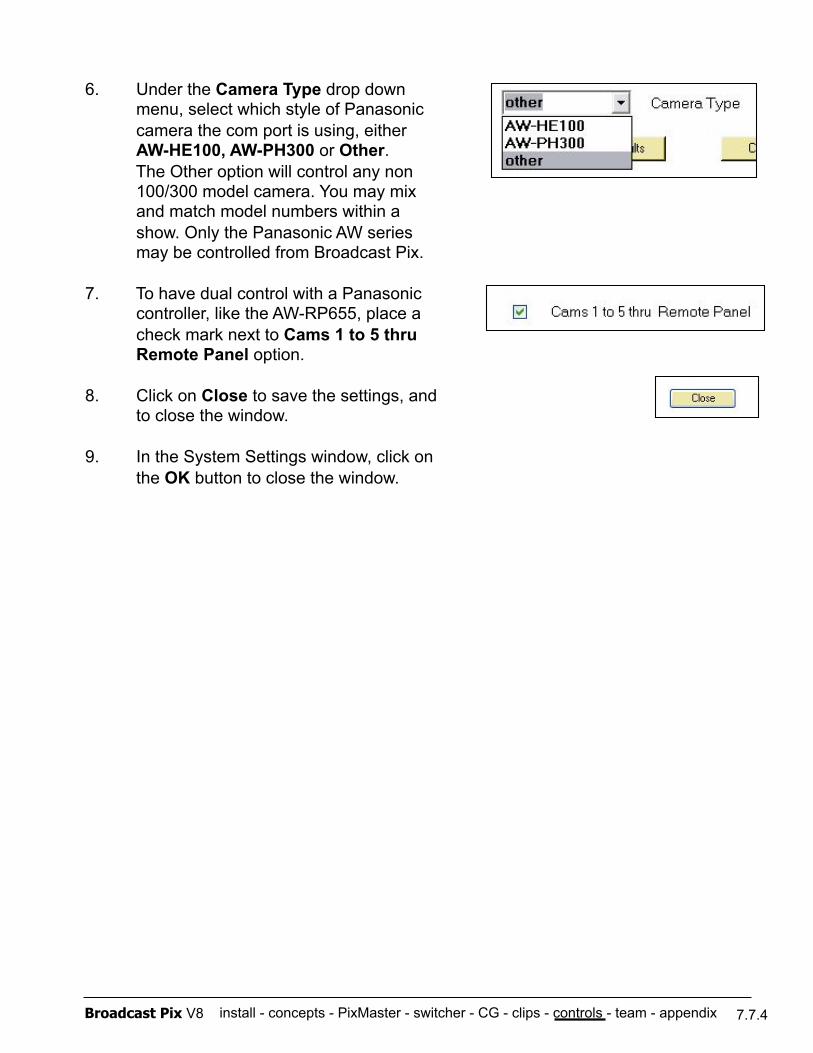
install - concepts - PixMaster - switcher - CG - clips - controls - team - appendix Broadcast Pix V8 7.7.4
6. Under the Camera Type drop down menu, select which style of Panasonic camera the com port is using, either AW-HE100, AW-PH300 or Other. The Other option will control any non 100/300 model camera. You may mix and match model numbers within a show. Only the Panasonic AW series may be controlled from Broadcast Pix.
7. To have dual control with a Panasonic controller, like the AW-RP655, place a check mark next to Cams 1 to 5 thru Remote Panel option.
8. Click on Close to save the settings, and to close the window.
9. In the System Settings window, click on the OK button to close the window.
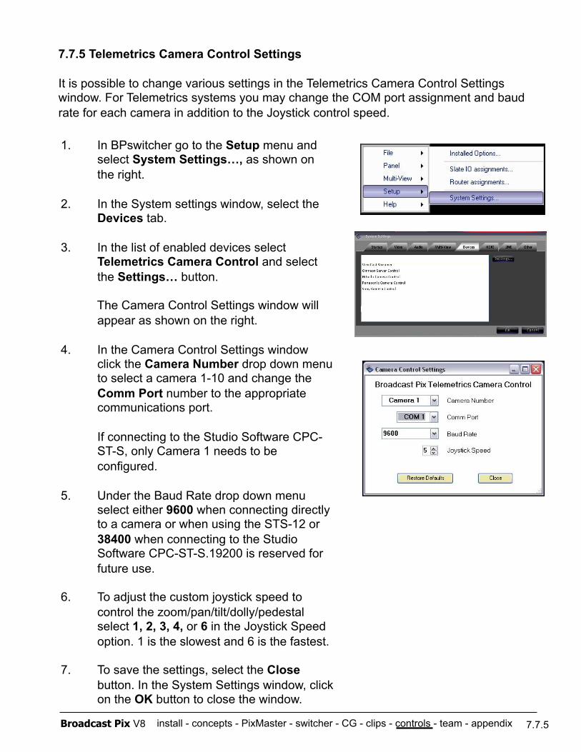
install - concepts - PixMaster - switcher - CG - clips - controls - team - appendix Broadcast Pix V8
7.7.5 Telemetrics Camera Control Settings
It is possible to change various settings in the Telemetrics Camera Control Settings window. For Telemetrics systems you may change the COM port assignment and baud rate for each camera in addition to the Joystick control speed.
7.7.5
1. In BPswitcher go to the Setup menu and select System Settings…, as shown on the right.
2. In the System settings window, select the Devices tab.
3. In the list of enabled devices select Telemetrics Camera Control and select the Settings… button.
The Camera Control Settings window will appear as shown on the right.
4. In the Camera Control Settings window click the Camera Number drop down menu to select a camera 1-10 and change the Comm Port number to the appropriate communications port.
If connecting to the Studio Software CPC-ST-S, only Camera 1 needs to be configured.
5. Under the Baud Rate drop down menu select either 9600 when connecting directly to a camera or when using the STS-12 or 38400 when connecting to the Studio Software CPC-ST-S.19200 is reserved for future use.
6. To adjust the custom joystick speed to control the zoom/pan/tilt/dolly/pedestal select 1, 2, 3, 4, or 6 in the Joystick Speed option. 1 is the slowest and 6 is the fastest.
7. To save the settings, select the Close button. In the System Settings window, click on the OK button to close the window.
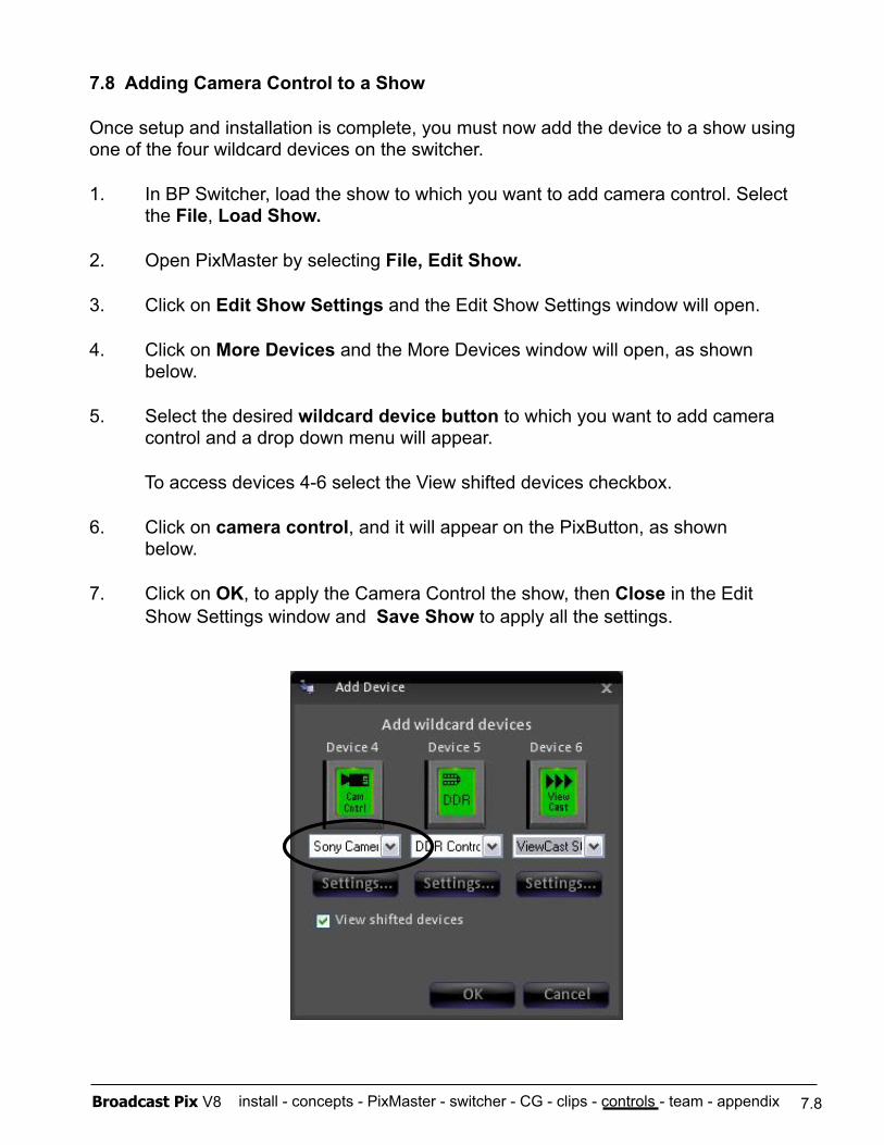
install - concepts - PixMaster - switcher - CG - clips - controls - team - appendix Broadcast Pix V8
7.8 Adding Camera Control to a Show
Once setup and installation is complete, you must now add the device to a show using one of the four wildcard devices on the switcher.
1. In BP Switcher, load the show to which you want to add camera control. Select the File, Load Show.
2. Open PixMaster by selecting File, Edit Show.
3. Click on Edit Show Settings and the Edit Show Settings window will open.
4. Click on More Devices and the More Devices window will open, as shown below.
5. Select the desired wildcard device button to which you want to add camera control and a drop down menu will appear.
To access devices 4-6 select the View shifted devices checkbox.
6. Click on camera control, and it will appear on the PixButton, as shown below.
7. Click on OK, to apply the Camera Control the show, then Close in the Edit Show Settings window and Save Show to apply all the settings.
7.8
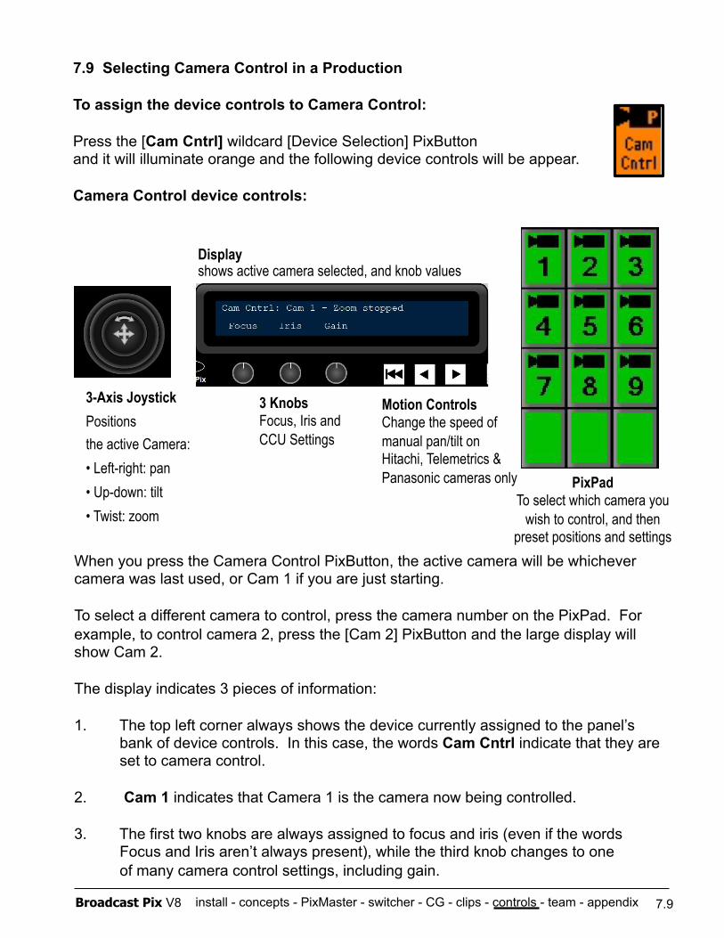
install - concepts - PixMaster - switcher - CG - clips - controls - team - appendix Broadcast Pix V8
3-Axis Joystick Positions the active Camera: • Left-right: pan • Up-down: tilt • Twist: zoom
7.9 Selecting Camera Control in a Production
To assign the device controls to Camera Control:
Press the [Cam Cntrl] wildcard [Device Selection] PixButton and it will illuminate orange and the following device controls will be appear.
Camera Control device controls:
3 Knobs Focus, Iris and CCU Settings
Display shows active camera selected, and knob values
PixPad To select which camera you
wish to control, and then preset positions and settings
Motion Controls Change the speed of manual pan/tilt on Hitachi, Telemetrics & Panasonic cameras only
When you press the Camera Control PixButton, the active camera will be whichever camera was last used, or Cam 1 if you are just starting.
To select a different camera to control, press the camera number on the PixPad. For example, to control camera 2, press the [Cam 2] PixButton and the large display will show Cam 2.
The display indicates 3 pieces of information:
1. The top left corner always shows the device currently assigned to the panel’s bank of device controls. In this case, the words Cam Cntrl indicate that they are set to camera control.
2. Cam 1 indicates that Camera 1 is the camera now being controlled.
3. The first two knobs are always assigned to focus and iris (even if the words Focus and Iris aren’t always present), while the third knob changes to one of many camera control settings, including gain.
7.9
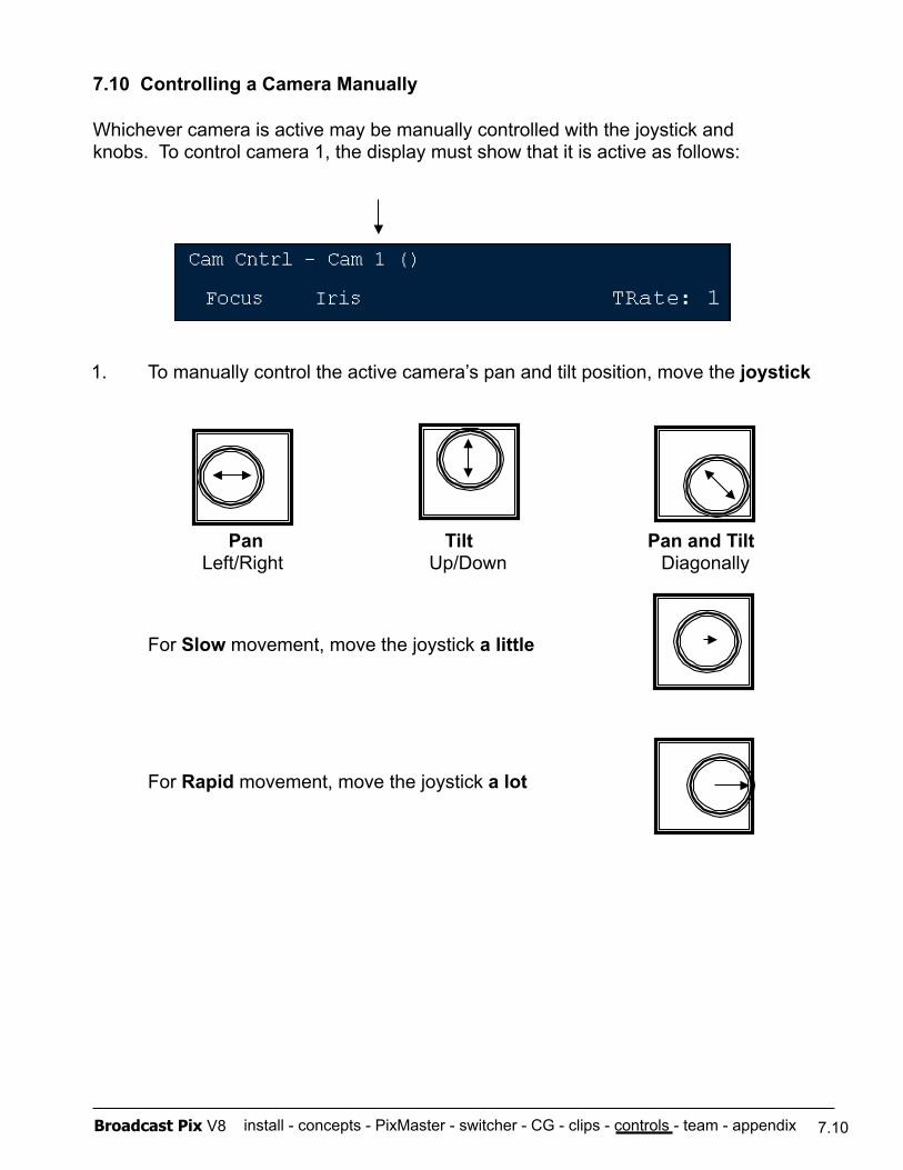
install - concepts - PixMaster - switcher - CG - clips - controls - team - appendix Broadcast Pix V8
7.10 Controlling a Camera Manually
Whichever camera is active may be manually controlled with the joystick and knobs. To control camera 1, the display must show that it is active as follows:
1. To manually control the active camera’s pan and tilt position, move the joystick
For Slow movement, move the joystick a little
For Rapid movement, move the joystick a lot
Pan Tilt Pan and Tilt Left/Right Up/Down Diagonally
7.10
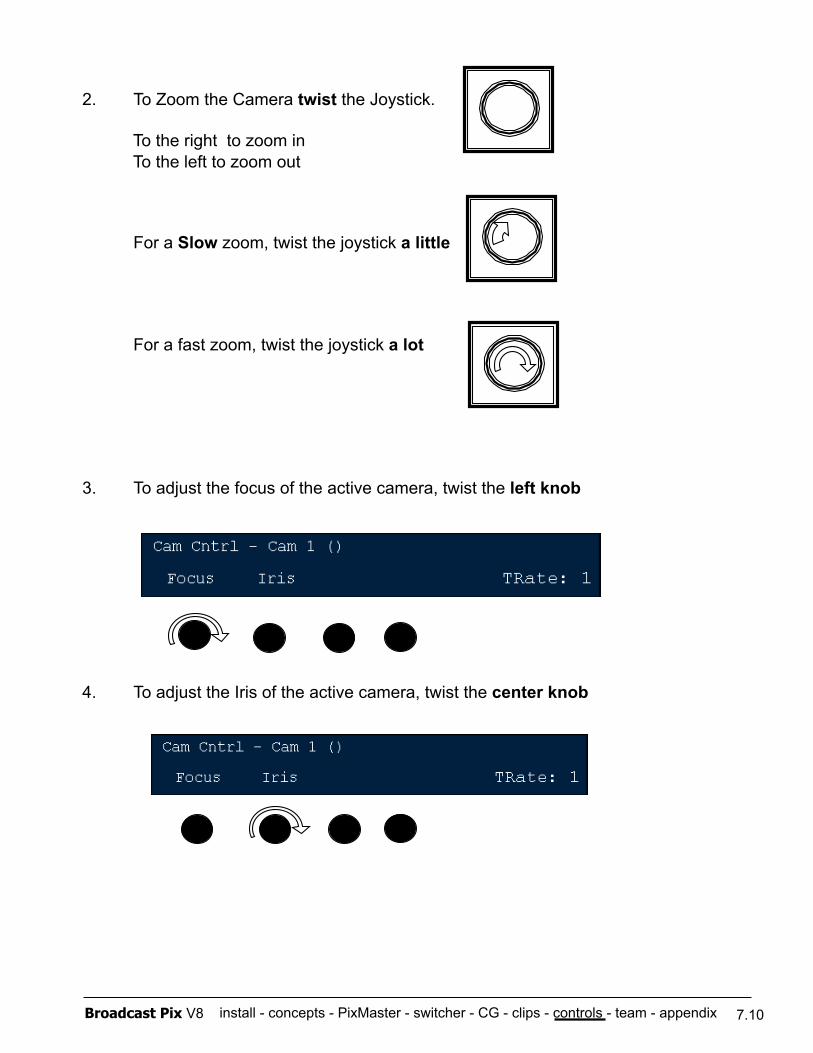
install - concepts - PixMaster - switcher - CG - clips - controls - team - appendix Broadcast Pix V8
2. To Zoom the Camera twist the Joystick.
To the right to zoom in To the left to zoom out
For a Slow zoom, twist the joystick a little
For a fast zoom, twist the joystick a lot
3. To adjust the focus of the active camera, twist the left knob
4. To adjust the Iris of the active camera, twist the center knob
7.10
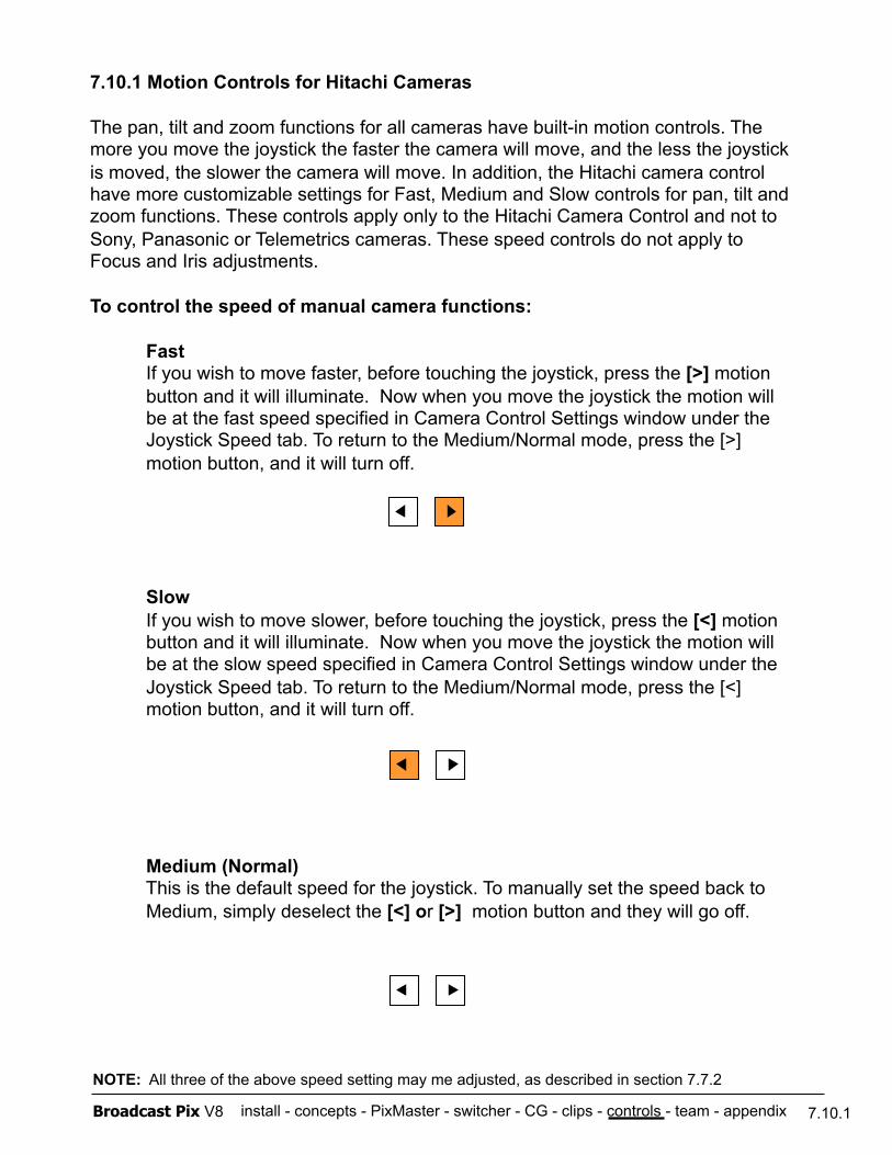
install - concepts - PixMaster - switcher - CG - clips - controls - team - appendix Broadcast Pix V8
7.10.1 Motion Controls for Hitachi Cameras
The pan, tilt and zoom functions for all cameras have built-in motion controls. The more you move the joystick the faster the camera will move, and the less the joystick is moved, the slower the camera will move. In addition, the Hitachi camera control have more customizable settings for Fast, Medium and Slow controls for pan, tilt and zoom functions. These controls apply only to the Hitachi Camera Control and not to Sony, Panasonic or Telemetrics cameras. These speed controls do not apply to Focus and Iris adjustments.
To control the speed of manual camera functions:
Fast If you wish to move faster, before touching the joystick, press the [>] motion
button and it will illuminate. Now when you move the joystick the motion will be at the fast speed specified in Camera Control Settings window under the Joystick Speed tab. To return to the Medium/Normal mode, press the [>] motion button, and it will turn off.
Slow If you wish to move slower, before touching the joystick, press the [<] motion
button and it will illuminate. Now when you move the joystick the motion will be at the slow speed specified in Camera Control Settings window under the Joystick Speed tab. To return to the Medium/Normal mode, press the [<] motion button, and it will turn off.
Medium (Normal) This is the default speed for the joystick. To manually set the speed back to
Medium, simply deselect the [<] or [>] motion button and they will go off.
7.10.1
NOTE: All three of the above speed setting may me adjusted, as described in section 7.7.2
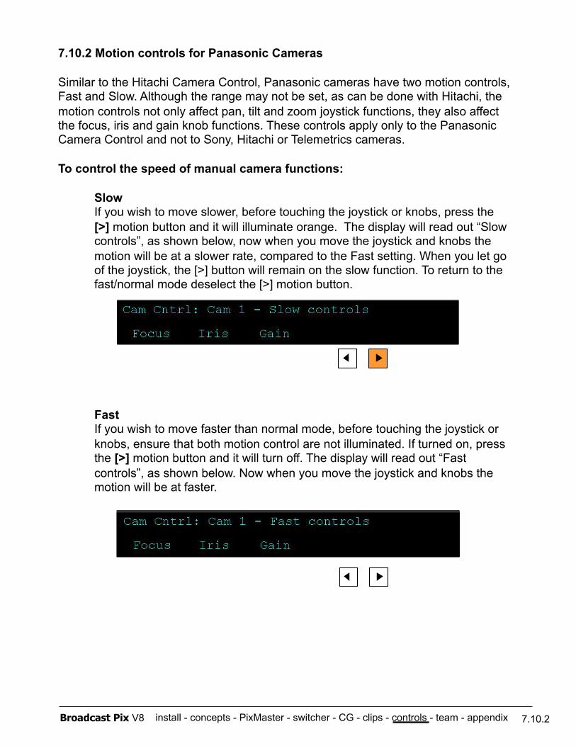
install - concepts - PixMaster - switcher - CG - clips - controls - team - appendix Broadcast Pix V8
7.10.2 Motion controls for Panasonic Cameras
Similar to the Hitachi Camera Control, Panasonic cameras have two motion controls, Fast and Slow. Although the range may not be set, as can be done with Hitachi, the motion controls not only affect pan, tilt and zoom joystick functions, they also affect the focus, iris and gain knob functions. These controls apply only to the Panasonic Camera Control and not to Sony, Hitachi or Telemetrics cameras.
To control the speed of manual camera functions:
Slow If you wish to move slower, before touching the joystick or knobs, press the
[>] motion button and it will illuminate orange. The display will read out “Slow controls”, as shown below, now when you move the joystick and knobs the motion will be at a slower rate, compared to the Fast setting. When you let go of the joystick, the [>] button will remain on the slow function. To return to the fast/normal mode deselect the [>] motion button.
Fast If you wish to move faster than normal mode, before touching the joystick or
knobs, ensure that both motion control are not illuminated. If turned on, press the [>] motion button and it will turn off. The display will read out “Fast controls”, as shown below. Now when you move the joystick and knobs the motion will be at faster.
7.10.2
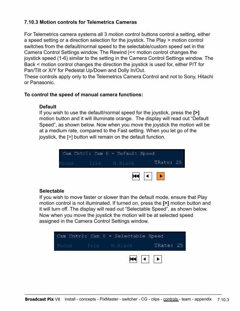
install - concepts - PixMaster - switcher - CG - clips - controls - team - appendix Broadcast Pix V8
7.10.3 Motion controls for Telemetrics Cameras
For Telemetrics camera systems all 3 motion control buttons control a setting, either a speed setting or a direction selection for the joystick. The Play > motion control switches from the default/normal speed to the selectable/custom speed set in the Camera Control Settings window. The Rewind |<< motion control changes the joystick speed (1-6) similar to the setting in the Camera Control Settings window. The Back < motion control changes the direction the joystick is used for, either P/T for Pan/Tilt or X/Y for Pedestal Up/Down and Dolly In/Out. These controls apply only to the Telemetrics Camera Control and not to Sony, Hitachi or Panasonic.
To control the speed of manual camera functions:
Default If you wish to use the default/normal speed for the joystick, press the [>]
motion button and it will illuminate orange. The display will read out “Default Speed”, as shown below. Now when you move the joystick the motion will be at a medium rate, compared to the Fast setting. When you let go of the joystick, the [>] button will remain on the default function.
Selectable If you wish to move faster or slower than the default mode, ensure that Play
motion control is not illuminated. If turned on, press the [>] motion button and it will turn off. The display will read out “Selectable Speed”, as shown below. Now when you move the joystick the motion will be at selected speed assigned in the Camera Control Settings window.
7.10.3
Focus Iris M.Black
Focus Iris M.Black
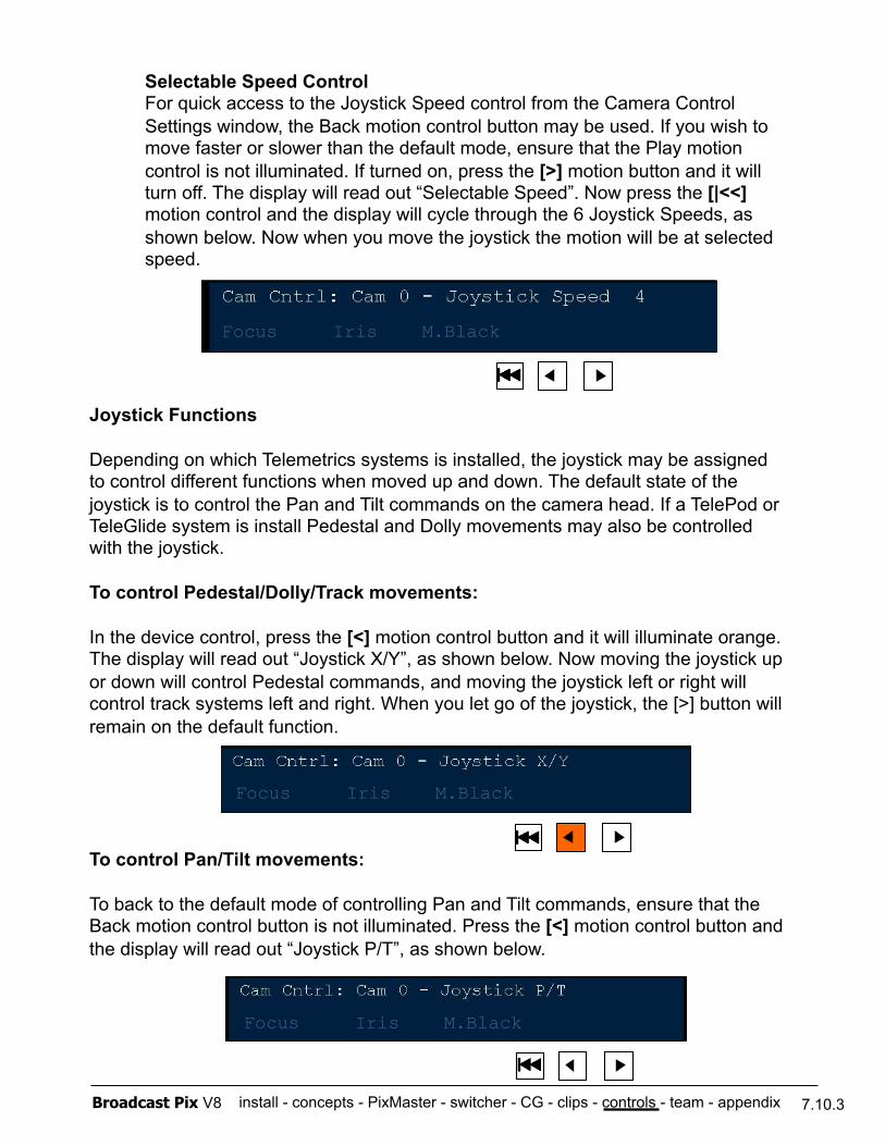
install - concepts - PixMaster - switcher - CG - clips - controls - team - appendix Broadcast Pix V8
Selectable Speed Control For quick access to the Joystick Speed control from the Camera Control
Settings window, the Back motion control button may be used. If you wish to move faster or slower than the default mode, ensure that the Play motion control is not illuminated. If turned on, press the [>] motion button and it will turn off. The display will read out “Selectable Speed”. Now press the [|<<] motion control and the display will cycle through the 6 Joystick Speeds, as shown below. Now when you move the joystick the motion will be at selected speed.
Joystick Functions
Depending on which Telemetrics systems is installed, the joystick may be assigned to control different functions when moved up and down. The default state of the joystick is to control the Pan and Tilt commands on the camera head. If a TelePod or TeleGlide system is install Pedestal and Dolly movements may also be controlled with the joystick.
To control Pedestal/Dolly/Track movements:
In the device control, press the [<] motion control button and it will illuminate orange. The display will read out “Joystick X/Y”, as shown below. Now moving the joystick up or down will control Pedestal commands, and moving the joystick left or right will control track systems left and right. When you let go of the joystick, the [>] button will remain on the default function.
To control Pan/Tilt movements:
To back to the default mode of controlling Pan and Tilt commands, ensure that the Back motion control button is not illuminated. Press the [<] motion control button and the display will read out “Joystick P/T”, as shown below.
7.10.3
Focus Iris M.Black
Focus Iris M.Black
Focus Iris M.Black
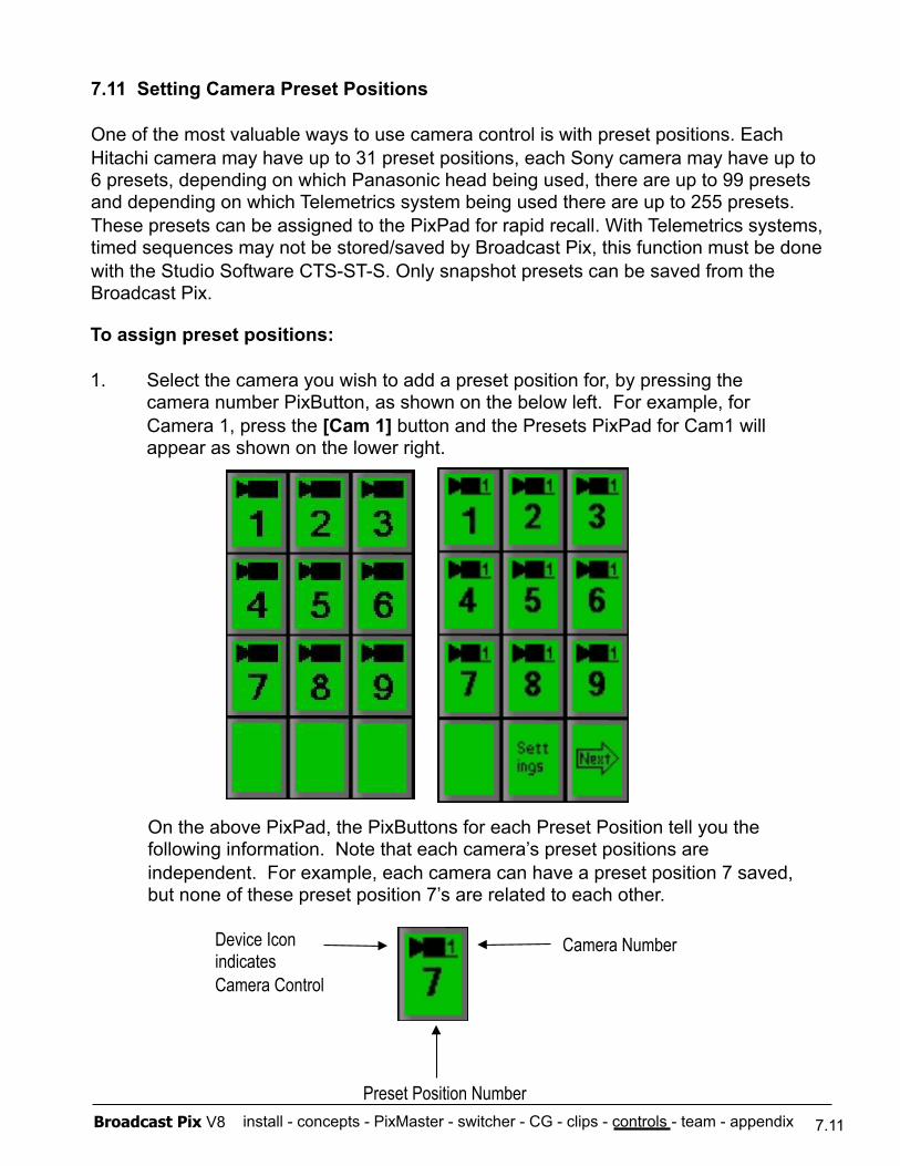
install - concepts - PixMaster - switcher - CG - clips - controls - team - appendix Broadcast Pix V8
7.11 Setting Camera Preset Positions
One of the most valuable ways to use camera control is with preset positions. Each Hitachi camera may have up to 31 preset positions, each Sony camera may have up to 6 presets, depending on which Panasonic head being used, there are up to 99 presets and depending on which Telemetrics system being used there are up to 255 presets. These presets can be assigned to the PixPad for rapid recall. With Telemetrics systems, timed sequences may not be stored/saved by Broadcast Pix, this function must be done with the Studio Software CTS-ST-S. Only snapshot presets can be saved from the Broadcast Pix.
Device Icon indicates Camera Control
Camera Number
Preset Position Number
On the above PixPad, the PixButtons for each Preset Position tell you the following information. Note that each camera’s preset positions are independent. For example, each camera can have a preset position 7 saved, but none of these preset position 7’s are related to each other.
To assign preset positions:
1. Select the camera you wish to add a preset position for, by pressing the camera number PixButton, as shown on the below left. For example, for Camera 1, press the [Cam 1] button and the Presets PixPad for Cam1 will appear as shown on the lower right.
7.11
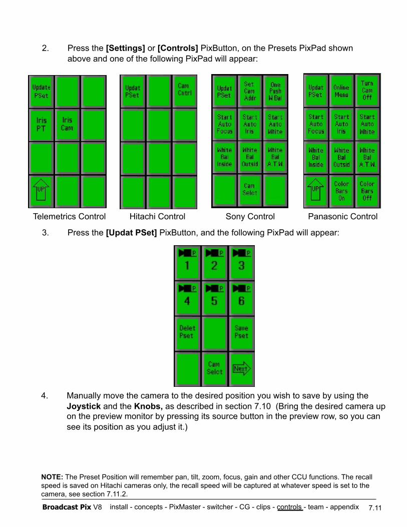
install - concepts - PixMaster - switcher - CG - clips - controls - team - appendix Broadcast Pix V8
2. Press the [Settings] or [Controls] PixButton, on the Presets PixPad shown above and one of the following PixPad will appear:
3. Press the [Updat PSet] PixButton, and the following PixPad will appear:
4. Manually move the camera to the desired position you wish to save by using the Joystick and the Knobs, as described in section 7.10 (Bring the desired camera up on the preview monitor by pressing its source button in the preview row, so you can see its position as you adjust it.)
NOTE: The Preset Position will remember pan, tilt, zoom, focus, gain and other CCU functions. The recall speed is saved on Hitachi cameras only, the recall speed will be captured at whatever speed is set to the camera, see section 7.11.2.
7.11
Telemetrics Control Hitachi Control Sony Control Panasonic Control
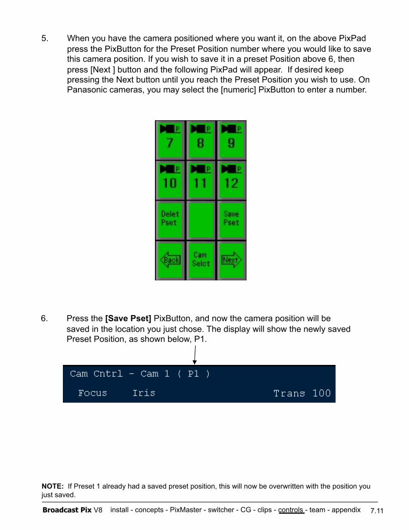
install - concepts - PixMaster - switcher - CG - clips - controls - team - appendix Broadcast Pix V8
5. When you have the camera positioned where you want it, on the above PixPad press the PixButton for the Preset Position number where you would like to save this camera position. If you wish to save it in a preset Position above 6, then press [Next ] button and the following PixPad will appear. If desired keep pressing the Next button until you reach the Preset Position you wish to use. On Panasonic cameras, you may select the [numeric] PixButton to enter a number.
6. Press the [Save Pset] PixButton, and now the camera position will be saved in the location you just chose. The display will show the newly saved Preset Position, as shown below, P1.
NOTE: If Preset 1 already had a saved preset position, this will now be overwritten with the position you just saved.
7.11
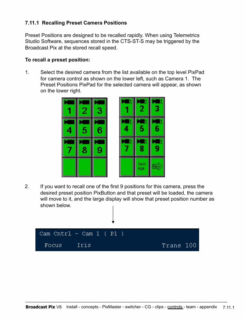
install - concepts - PixMaster - switcher - CG - clips - controls - team - appendix Broadcast Pix V8
7.11.1 Recalling Preset Camera Positions
Preset Positions are designed to be recalled rapidly. When using Telemetrics Studio Software, sequences stored in the CTS-ST-S may be triggered by the Broadcast Pix at the stored recall speed.
To recall a preset position:
1. Select the desired camera from the list available on the top level PixPad for camera control as shown on the lower left, such as Camera 1. The Preset Positions PixPad for the selected camera will appear, as shown on the lower right.
2. If you want to recall one of the first 9 positions for this camera, press the desired preset position PixButton and that preset will be loaded, the camera will move to it, and the large display will show that preset position number as shown below.
7.11.1
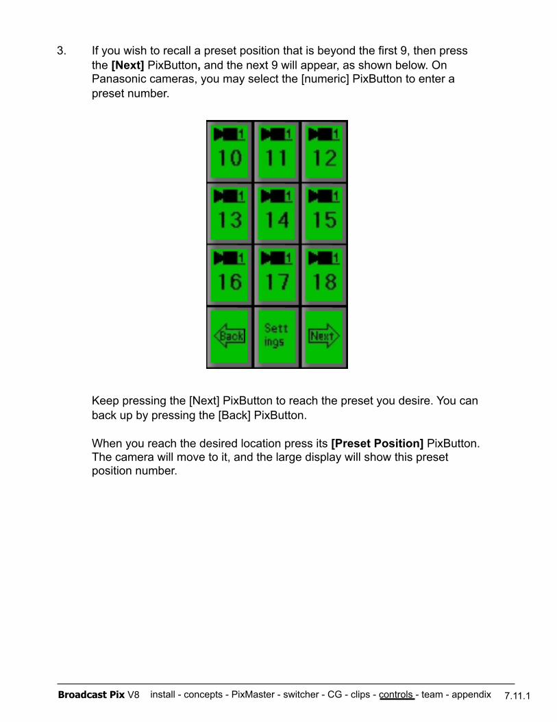
install - concepts - PixMaster - switcher - CG - clips - controls - team - appendix Broadcast Pix V8
3. If you wish to recall a preset position that is beyond the first 9, then press the [Next] PixButton, and the next 9 will appear, as shown below. On Panasonic cameras, you may select the [numeric] PixButton to enter a preset number.
Keep pressing the [Next] PixButton to reach the preset you desire. You can back up by pressing the [Back] PixButton.
When you reach the desired location press its [Preset Position] PixButton. The camera will move to it, and the large display will show this preset position number.
7.11.1
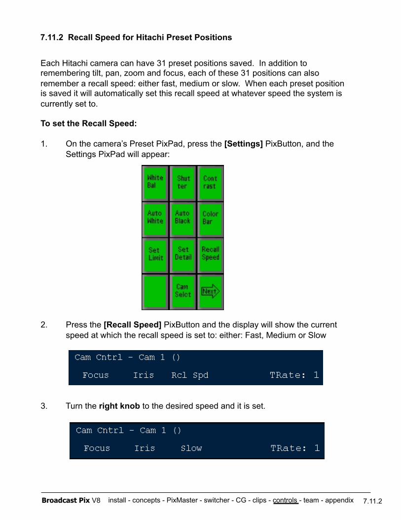
install - concepts - PixMaster - switcher - CG - clips - controls - team - appendix Broadcast Pix V8
7.11.2 Recall Speed for Hitachi Preset Positions
Each Hitachi camera can have 31 preset positions saved. In addition to remembering tilt, pan, zoom and focus, each of these 31 positions can also remember a recall speed: either fast, medium or slow. When each preset position is saved it will automatically set this recall speed at whatever speed the system is currently set to.
To set the Recall Speed:
1. On the camera’s Preset PixPad, press the [Settings] PixButton, and the Settings PixPad will appear:
2. Press the [Recall Speed] PixButton and the display will show the current speed at which the recall speed is set to: either: Fast, Medium or Slow
3. Turn the right knob to the desired speed and it is set.
7.11.2
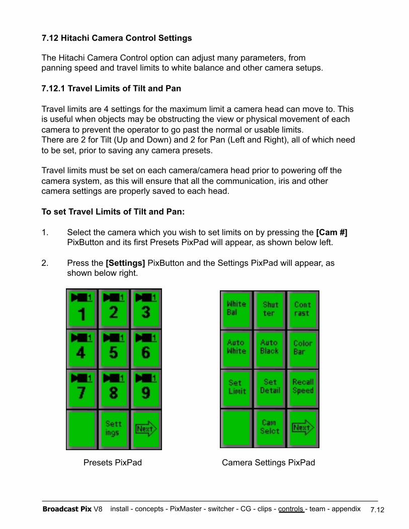
install - concepts - PixMaster - switcher - CG - clips - controls - team - appendix Broadcast Pix V8
7.12 Hitachi Camera Control Settings
The Hitachi Camera Control option can adjust many parameters, from panning speed and travel limits to white balance and other camera setups.
7.12.1 Travel Limits of Tilt and Pan
Travel limits are 4 settings for the maximum limit a camera head can move to. This is useful when objects may be obstructing the view or physical movement of each camera to prevent the operator to go past the normal or usable limits. There are 2 for Tilt (Up and Down) and 2 for Pan (Left and Right), all of which need to be set, prior to saving any camera presets.
Travel limits must be set on each camera/camera head prior to powering off the camera system, as this will ensure that all the communication, iris and other camera settings are properly saved to each head.
To set Travel Limits of Tilt and Pan:
1. Select the camera which you wish to set limits on by pressing the [Cam #] PixButton and its first Presets PixPad will appear, as shown below left.
2. Press the [Settings] PixButton and the Settings PixPad will appear, as shown below right.
7.12
Presets PixPad Camera Settings PixPad
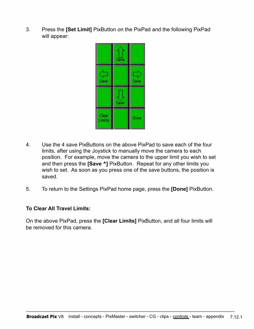
install - concepts - PixMaster - switcher - CG - clips - controls - team - appendix Broadcast Pix V8
3. Press the [Set Limit] PixButton on the PixPad and the following PixPad will appear:
4. Use the 4 save PixButtons on the above PixPad to save each of the four limits, after using the Joystick to manually move the camera to each position. For example, move the camera to the upper limit you wish to set and then press the [Save ^] PixButton. Repeat for any other limits you wish to set. As soon as you press one of the save buttons, the position is saved.
5. To return to the Settings PixPad home page, press the [Done] PixButton.
To Clear All Travel Limits:
On the above PixPad, press the [Clear Limits] PixButton, and all four limits will be removed for this camera.
7.12.1
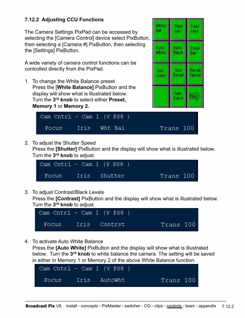
install - concepts - PixMaster - switcher - CG - clips - controls - team - appendix Broadcast Pix V8
7.12.2 Adjusting CCU Functions
The Camera Settings PixPad can be accessed by selecting the [Camera Control] device select PixButton, then selecting a [Camera #] PixButton, then selecting the [Settings] PixButton.
A wide variety of camera control functions can be controlled directly from the PixPad.
1. To change the White Balance preset Press the [White Balance] PixButton and the
display will show what is illustrated below. Turn the 3rd knob to select either Preset,
Memory 1 or Memory 2.
2. To adjust the Shutter Speed Press the [Shutter] PixButton and the display will show what is illustrated below.
Turn the 3rd knob to adjust.
3. To adjust Contrast/Black Levels Press the [Contrast] PixButton and the display will show what is illustrated below. Turn the 3rd knob to adjust.
4. To activate Auto White Balance Press the [Auto White] PixButton and the display will show what is illustrated
below. Turn the 3rd knob to white balance the camera. The setting will be saved in either in Memory 1 or Memory 2 of the above White Balance function.
7.12.2
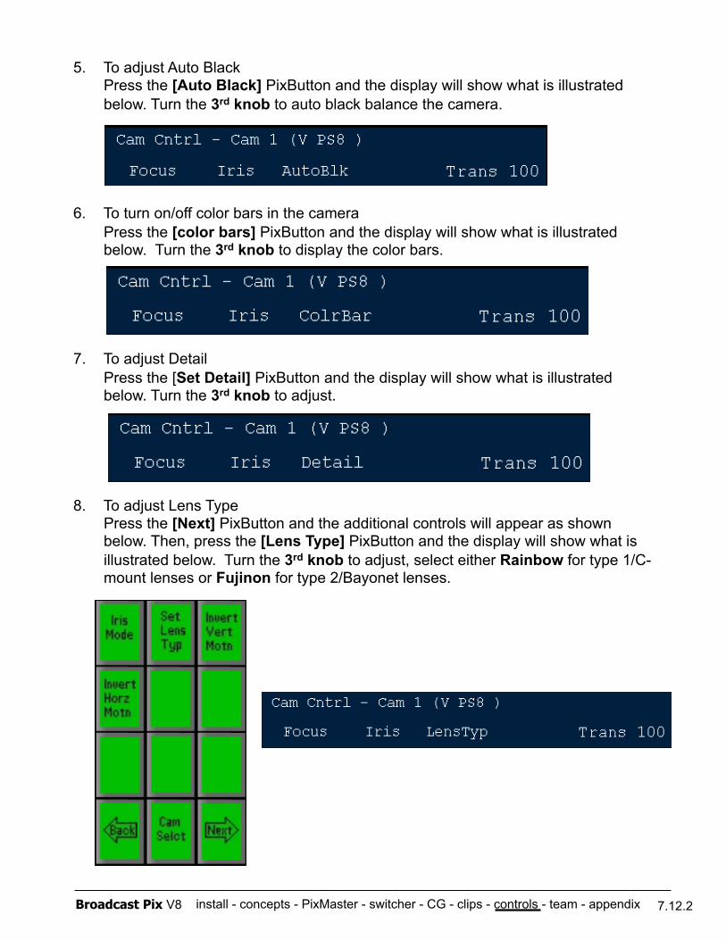
install - concepts - PixMaster - switcher - CG - clips - controls - team - appendix Broadcast Pix V8
5. To adjust Auto Black Press the [Auto Black] PixButton and the display will show what is illustrated
below. Turn the 3rd knob to auto black balance the camera.
6. To turn on/off color bars in the camera Press the [color bars] PixButton and the display will show what is illustrated
below. Turn the 3rd knob to display the color bars.
7. To adjust Detail Press the [Set Detail] PixButton and the display will show what is illustrated
below. Turn the 3rd knob to adjust.
8. To adjust Lens Type Press the [Next] PixButton and the additional controls will appear as shown
below. Then, press the [Lens Type] PixButton and the display will show what is illustrated below. Turn the 3rd knob to adjust, select either Rainbow for type 1/C-mount lenses or Fujinon for type 2/Bayonet lenses.
7.12.2
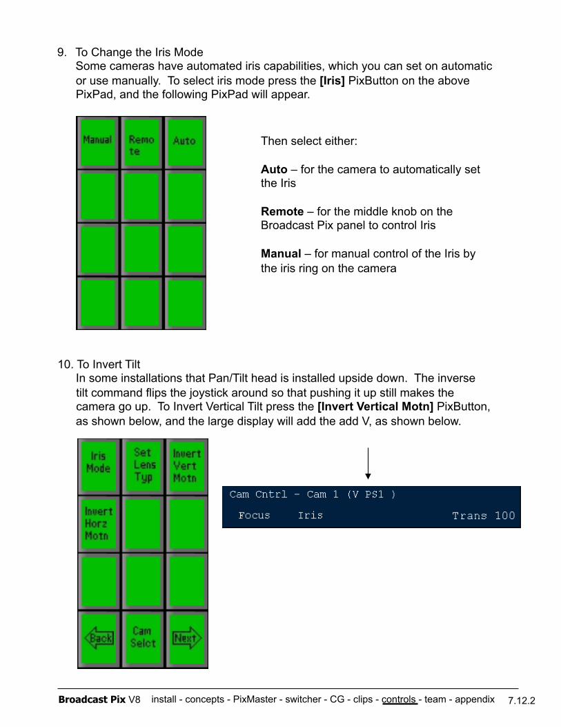
install - concepts - PixMaster - switcher - CG - clips - controls - team - appendix Broadcast Pix V8
9. To Change the Iris Mode Some cameras have automated iris capabilities, which you can set on automatic or use manually. To select iris mode press the [Iris] PixButton on the above PixPad, and the following PixPad will appear.
Then select either:
Auto – for the camera to automatically set the Iris
Remote – for the middle knob on the Broadcast Pix panel to control Iris
Manual – for manual control of the Iris by the iris ring on the camera
10. To Invert Tilt In some installations that Pan/Tilt head is installed upside down. The inverse tilt command flips the joystick around so that pushing it up still makes the camera go up. To Invert Vertical Tilt press the [Invert Vertical Motn] PixButton,
as shown below, and the large display will add the add V, as shown below.
7.12.2
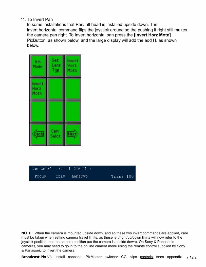
install - concepts - PixMaster - switcher - CG - clips - controls - team - appendix Broadcast Pix V8
11. To Invert Pan In some installations that Pan/Tilt head is installed upside down. The invert horizontal command flips the joystick around so the pushing it right still makes the camera pan right. To Invert horizontal pan press the [Invert Horz Motn] PixButton, as shown below, and the large display will add the add H, as shown below.
7.12.2
NOTE: When the camera is mounted upside down, and so these two invert commands are applied, care must be taken when setting camera travel limits, as these left/right/up/down limits will now refer to the joystick position, not the camera position (as the camera is upside down). On Sony & Panasonic cameras, you may need to go in to the on line camera menu using the remote control supplied by Sony & Panasonic to invert the camera.
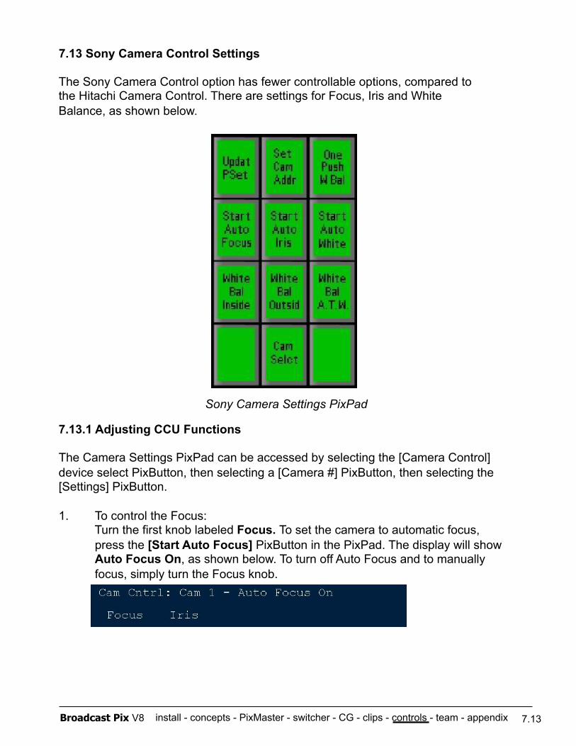
install - concepts - PixMaster - switcher - CG - clips - controls - team - appendix Broadcast Pix V8
7.13 Sony Camera Control Settings
The Sony Camera Control option has fewer controllable options, compared to the Hitachi Camera Control. There are settings for Focus, Iris and White Balance, as shown below.
7.13.1 Adjusting CCU Functions
The Camera Settings PixPad can be accessed by selecting the [Camera Control] device select PixButton, then selecting a [Camera #] PixButton, then selecting the [Settings] PixButton.
1. To control the Focus: Turn the first knob labeled Focus. To set the camera to automatic focus, press the [Start Auto Focus] PixButton in the PixPad. The display will show Auto Focus On, as shown below. To turn off Auto Focus and to manually focus, simply turn the Focus knob.
7.13
Sony Camera Settings PixPad
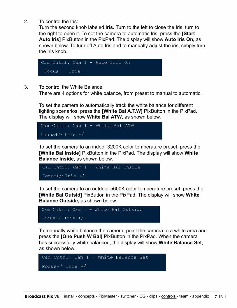
install - concepts - PixMaster - switcher - CG - clips - controls - team - appendix Broadcast Pix V8
2. To control the Iris: Turn the second knob labeled Iris. Turn to the left to close the Iris, turn to the right to open it. To set the camera to automatic Iris, press the [Start Auto Iris] PixButton in the PixPad. The display will show Auto Iris On, as shown below. To turn off Auto Iris and to manually adjust the iris, simply turn the Iris knob.
3. To control the White Balance: There are 4 options for white balance, from preset to manual to automatic.
To set the camera to automatically track the white balance for different lighting scenarios, press the [White Bal A.T.W] PixButton in the PixPad. The display will show White Bal ATW, as shown below.
To set the camera to an indoor 3200K color temperature preset, press the [White Bal Inside] PixButton in the PixPad. The display will show White Balance Inside, as shown below.
To set the camera to an outdoor 5600K color temperature preset, press the [White Bal Outsid] PixButton in the PixPad. The display will show White Balance Outside, as shown below.
To manually white balance the camera, point the camera to a white area and press the [One Push W Bal] PixButton in the PixPad. When the camera has successfully white balanced, the display will show White Balance Set, as shown below.
7.13.1
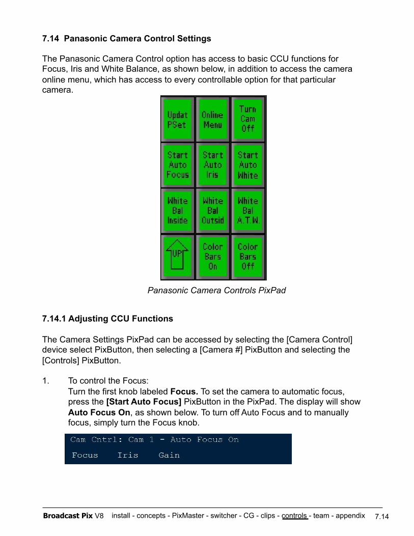
install - concepts - PixMaster - switcher - CG - clips - controls - team - appendix Broadcast Pix V8
7.14 Panasonic Camera Control Settings
The Panasonic Camera Control option has access to basic CCU functions for Focus, Iris and White Balance, as shown below, in addition to access the camera online menu, which has access to every controllable option for that particular camera.
7.14.1 Adjusting CCU Functions
The Camera Settings PixPad can be accessed by selecting the [Camera Control] device select PixButton, then selecting a [Camera #] PixButton and selecting the [Controls] PixButton.
1. To control the Focus: Turn the first knob labeled Focus. To set the camera to automatic focus, press the [Start Auto Focus] PixButton in the PixPad. The display will show Auto Focus On, as shown below. To turn off Auto Focus and to manually focus, simply turn the Focus knob.
7.14
Panasonic Camera Controls PixPad
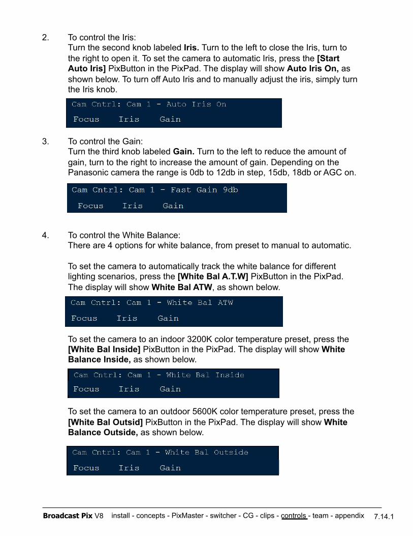
install - concepts - PixMaster - switcher - CG - clips - controls - team - appendix Broadcast Pix V8
2. To control the Iris: Turn the second knob labeled Iris. Turn to the left to close the Iris, turn to the right to open it. To set the camera to automatic Iris, press the [Start Auto Iris] PixButton in the PixPad. The display will show Auto Iris On, as shown below. To turn off Auto Iris and to manually adjust the iris, simply turn the Iris knob.
3. To control the Gain: Turn the third knob labeled Gain. Turn to the left to reduce the amount of gain, turn to the right to increase the amount of gain. Depending on the Panasonic camera the range is 0db to 12db in step, 15db, 18db or AGC on.
4. To control the White Balance: There are 4 options for white balance, from preset to manual to automatic.
To set the camera to automatically track the white balance for different lighting scenarios, press the [White Bal A.T.W] PixButton in the PixPad. The display will show White Bal ATW, as shown below.
To set the camera to an indoor 3200K color temperature preset, press the [White Bal Inside] PixButton in the PixPad. The display will show White Balance Inside, as shown below.
To set the camera to an outdoor 5600K color temperature preset, press the [White Bal Outsid] PixButton in the PixPad. The display will show White Balance Outside, as shown below.
7.14.1
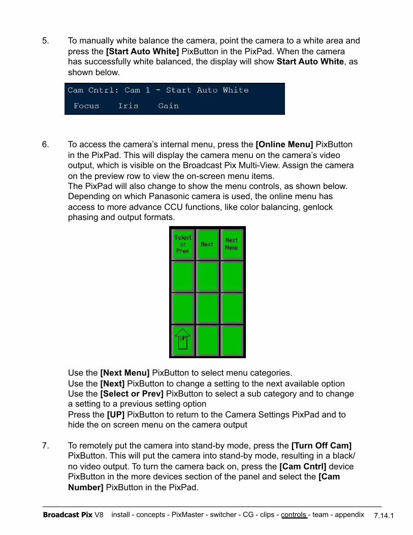
install - concepts - PixMaster - switcher - CG - clips - controls - team - appendix Broadcast Pix V8
5. To manually white balance the camera, point the camera to a white area and press the [Start Auto White] PixButton in the PixPad. When the camera has successfully white balanced, the display will show Start Auto White, as shown below.
6. To access the camera’s internal menu, press the [Online Menu] PixButton in the PixPad. This will display the camera menu on the camera’s video output, which is visible on the Broadcast Pix Multi-View. Assign the camera on the preview row to view the on-screen menu items. The PixPad will also change to show the menu controls, as shown below. Depending on which Panasonic camera is used, the online menu has access to more advance CCU functions, like color balancing, genlock phasing and output formats.
Use the [Next Menu] PixButton to select menu categories. Use the [Next] PixButton to change a setting to the next available option Use the [Select or Prev] PixButton to select a sub category and to change a setting to a previous setting option Press the [UP] PixButton to return to the Camera Settings PixPad and to hide the on screen menu on the camera output
7. To remotely put the camera into stand-by mode, press the [Turn Off Cam] PixButton. This will put the camera into stand-by mode, resulting in a black/no video output. To turn the camera back on, press the [Cam Cntrl] device PixButton in the more devices section of the panel and select the [Cam Number] PixButton in the PixPad.
7.14.1
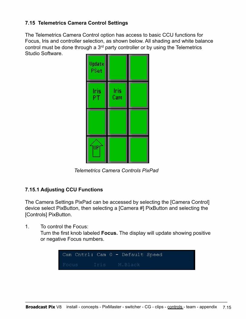
install - concepts - PixMaster - switcher - CG - clips - controls - team - appendix Broadcast Pix V8
7.15 Telemetrics Camera Control Settings
The Telemetrics Camera Control option has access to basic CCU functions for Focus, Iris and controller selection, as shown below. All shading and white balance control must be done through a 3rd party controller or by using the Telemetrics Studio Software.
7.15.1 Adjusting CCU Functions
The Camera Settings PixPad can be accessed by selecting the [Camera Control] device select PixButton, then selecting a [Camera #] PixButton and selecting the [Controls] PixButton.
1. To control the Focus: Turn the first knob labeled Focus. The display will update showing positive or negative Focus numbers.
7.15
Telemetrics Camera Controls PixPad
Focus Iris M.Black
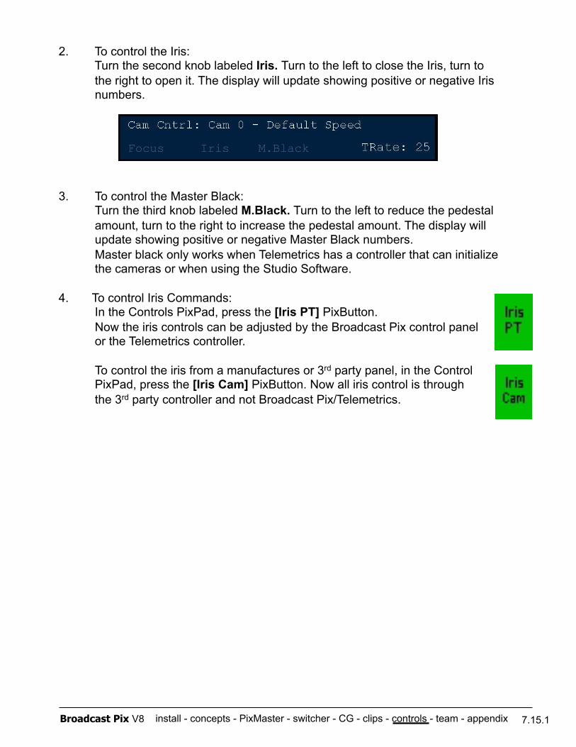
install - concepts - PixMaster - switcher - CG - clips - controls - team - appendix Broadcast Pix V8
2. To control the Iris: Turn the second knob labeled Iris. Turn to the left to close the Iris, turn to the right to open it. The display will update showing positive or negative Iris numbers.
3. To control the Master Black: Turn the third knob labeled M.Black. Turn to the left to reduce the pedestal amount, turn to the right to increase the pedestal amount. The display will update showing positive or negative Master Black numbers. Master black only works when Telemetrics has a controller that can initialize the cameras or when using the Studio Software.
4. To control Iris Commands: In the Controls PixPad, press the [Iris PT] PixButton. Now the iris controls can be adjusted by the Broadcast Pix control panel or the Telemetrics controller.
To control the iris from a manufactures or 3rd party panel, in the Control PixPad, press the [Iris Cam] PixButton. Now all iris control is through the 3rd party controller and not Broadcast Pix/Telemetrics.
7.15.1
Focus Iris M.Black
install - concepts - PixMaster - switcher - CG - clips - controls - team - appendix Broadcast Pix V8 7.16
7.16 Optional Audio-Follow-Video Control
As an option the Broadcast Pix switcher can provide control of virtually any external audio mixer, digital or analog, through a Musical Instrument Digital Interface (MIDI). Controls can be as simple as turning on a source when it transitions to program, or as complex as calling up scene changes to modify effect parameters like reverb, panning and equalization controls. This option can either use one of the computers COM or USB ports to communicate data to and from the audio mixer using MIDI commands. Some mixers, such as the Yamaha 01V or 01V96, have a ‘To Host’ adaptor (either a USB-B and/or 8-pin mini-din connection) and/or a standard 5-pin MIDI connection. You may use any connection to connect the workstation to your audio mixer. If using a standard MIDI connection, use the supplied M-Audio Uno USB to MIDI converter. If using a COM port you will need a 8-pin mini-din to DB9 serial cable (the same which is used for Sony Camera Control). For assistance about which connection to use, please contact technical support.
7.16.1 Enabling Audio-Follow
To use the Audio Follow Video, the System Option needs to be installed. On new systems this is preinstalled, to enable this option after the initial purchase, see section A.2 for more information.
7.16.2 Audio-Follow Activation
Enable your audio mixer to receive MIDI commands on the port in which you have connected to, either MIDI, USB, PC or other depending on the manufacturer. You must also activate your mixer to be able to receive (RX) and transmit (TX) Program Change and Control Change information for Audio-Follow to work properly. Refer to the MIDI section of your audio mixer’s manual on how to select these options, as they may be located in several menus.
It may be necessary to install drivers from your audio mixer, depending on which connection you are using with your audio mixer:
- If you are using a Serial cable to control your audio mixer, no extra drivers are needed. - If you are using a USB to MIDI converter, drivers are installed automatically using Windows XP when that device is plugged in. - If you are using a standard USB cable, you must install the appropriate drivers that came with your audio mixer.
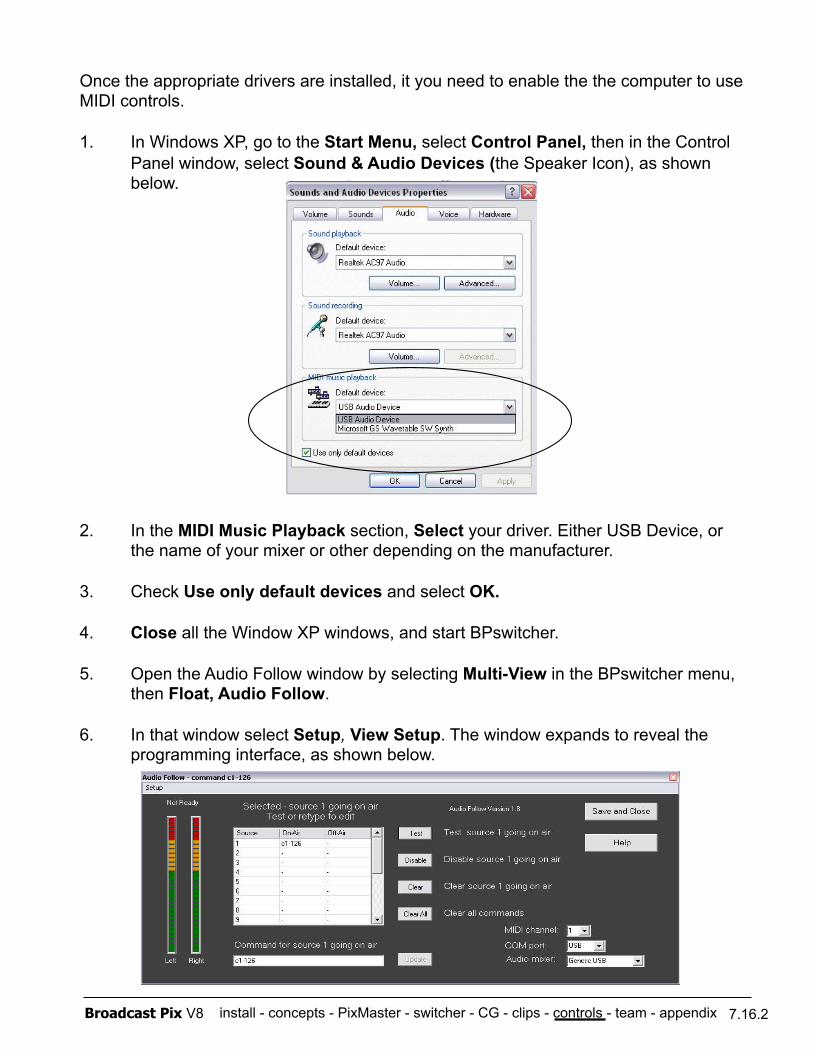
install - concepts - PixMaster - switcher - CG - clips - controls - team - appendix Broadcast Pix V8
Once the appropriate drivers are installed, it you need to enable the the computer to use MIDI controls.
1. In Windows XP, go to the Start Menu, select Control Panel, then in the Control Panel window, select Sound & Audio Devices (the Speaker Icon), as shown below.
2. In the MIDI Music Playback section, Select your driver. Either USB Device, or the name of your mixer or other depending on the manufacturer.
3. Check Use only default devices and select OK.
4. Close all the Window XP windows, and start BPswitcher.
5. Open the Audio Follow window by selecting Multi-View in the BPswitcher menu, then Float, Audio Follow.
6. In that window select Setup, View Setup. The window expands to reveal the programming interface, as shown below.
7.16.2
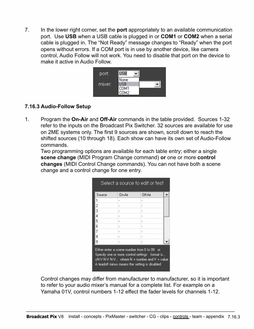
install - concepts - PixMaster - switcher - CG - clips - controls - team - appendix Broadcast Pix V8 7.16.3
7. In the lower right corner, set the port appropriately to an available communication port. Use USB when a USB cable is plugged in or COM1 or COM2 when a serial cable is plugged in. The “Not Ready” message changes to “Ready” when the port opens without errors. If a COM port is in use by another device, like camera control, Audio Follow will not work. You need to disable that port on the device to make it active in Audio Follow.
7.16.3 Audio-Follow Setup
1. Program the On-Air and Off-Air commands in the table provided. Sources 1-32 refer to the inputs on the Broadcast Pix Switcher. 32 sources are available for use on 2ME systems only. The first 9 sources are shown, scroll down to reach the shifted sources (10 through 18). Each show can have its own set of Audio-Follow commands. Two programming options are available for each table entry; either a single scene change (MIDI Program Change command) or one or more control changes (MIDI Control Change commands). You can not have both a scene change and a control change for one entry.
Control changes may differ from manufacturer to manufacturer, so it is important to refer to your audio mixer’s manual for a complete list. For example on a Yamaha 01V, control numbers 1-12 effect the fader levels for channels 1-12.
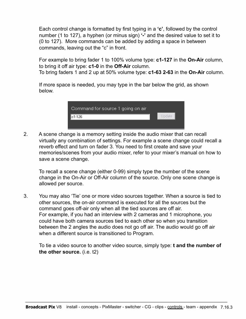
install - concepts - PixMaster - switcher - CG - clips - controls - team - appendix Broadcast Pix V8 7.16.3
Each control change is formatted by first typing in a ‘c’, followed by the control number (1 to 127), a hyphen (or minus sign) ‘-’ and the desired value to set it to (0 to 127). More commands can be added by adding a space in between commands, leaving out the “c” in front.
For example to bring fader 1 to 100% volume type: c1-127 in the On-Air column, to bring it off air type: c1-0 in the Off-Air column. To bring faders 1 and 2 up at 50% volume type: c1-63 2-63 in the On-Air column.
If more space is needed, you may type in the bar below the grid, as shown below.
2. A scene change is a memory setting inside the audio mixer that can recall virtually any combination of settings. For example a scene change could recall a reverb effect and turn on fader 3. You need to first create and save your memories/scenes from your audio mixer, refer to your mixer’s manual on how to save a scene change.
To recall a scene change (either 0-99) simply type the number of the scene change in the On-Air or Off-Air column of the source. Only one scene change is allowed per source.
3. You may also ‘Tie’ one or more video sources together. When a source is tied to other sources, the on-air command is executed for all the sources but the command goes off-air only when all the tied sources are off air. For example, if you had an interview with 2 cameras and 1 microphone, you could have both camera sources tied to each other so when you transition between the 2 angles the audio does not go off air. The audio would go off air when a different source is transitioned to Program.
To tie a video source to another video source, simply type: t and the number of the other source. (i.e. t2)
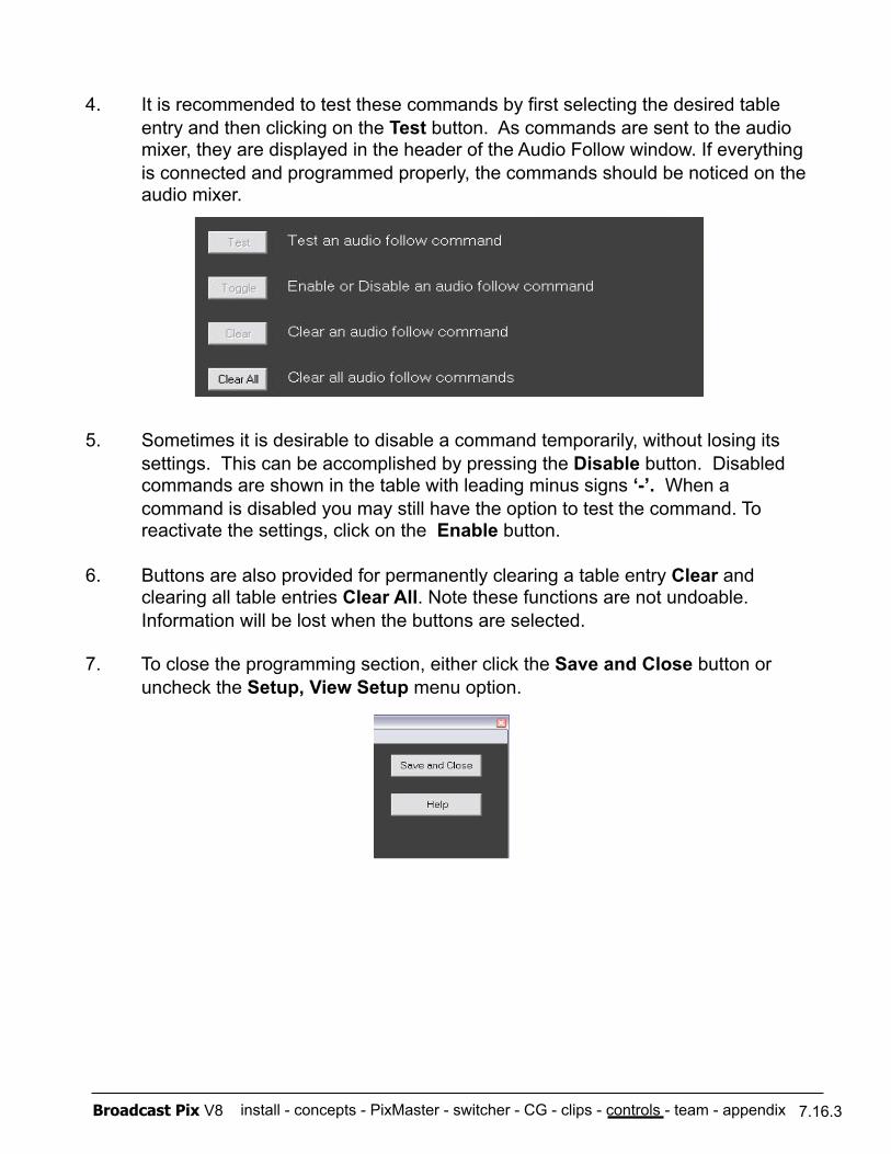
install - concepts - PixMaster - switcher - CG - clips - controls - team - appendix Broadcast Pix V8 7.16.3
4. It is recommended to test these commands by first selecting the desired table entry and then clicking on the Test button. As commands are sent to the audio mixer, they are displayed in the header of the Audio Follow window. If everything is connected and programmed properly, the commands should be noticed on the audio mixer.
5. Sometimes it is desirable to disable a command temporarily, without losing its settings. This can be accomplished by pressing the Disable button. Disabled commands are shown in the table with leading minus signs ‘-’. When a command is disabled you may still have the option to test the command. To reactivate the settings, click on the Enable button.
6. Buttons are also provided for permanently clearing a table entry Clear and clearing all table entries Clear All. Note these functions are not undoable. Information will be lost when the buttons are selected.
7. To close the programming section, either click the Save and Close button or uncheck the Setup, View Setup menu option.
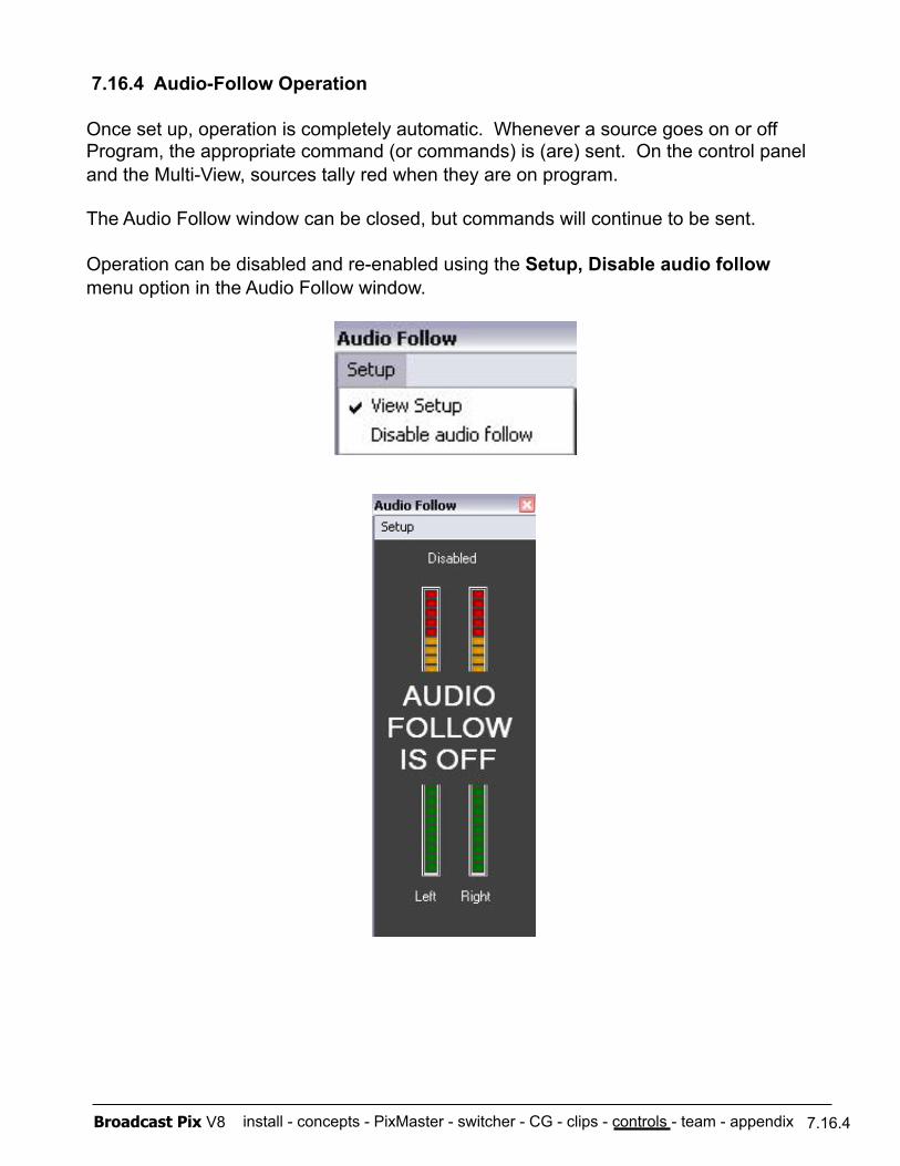
install - concepts - PixMaster - switcher - CG - clips - controls - team - appendix Broadcast Pix V8 7.16.4
7.16.4 Audio-Follow Operation
Once set up, operation is completely automatic. Whenever a source goes on or off Program, the appropriate command (or commands) is (are) sent. On the control panel and the Multi-View, sources tally red when they are on program.
The Audio Follow window can be closed, but commands will continue to be sent.
Operation can be disabled and re-enabled using the Setup, Disable audio follow menu option in the Audio Follow window.
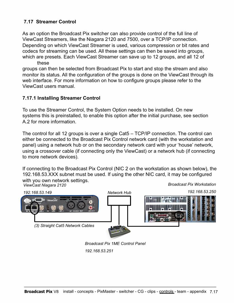
install - concepts - PixMaster - switcher - CG - clips - controls - team - appendix Broadcast Pix V8 7.17
7.17 Streamer Control
As an option the Broadcast Pix switcher can also provide control of the full line of ViewCast Streamers, like the Niagara 2120 and 7500, over a TCP/IP connection. Depending on which ViewCast Streamer is used, various compression or bit rates and codecs for streaming can be used. All these settings can then be saved into groups, which are presets. Each ViewCast Streamer can save up to 12 groups, and all 12 of
these groups can then be selected from Broadcast Pix to start and stop the stream and also monitor its status. All the configuration of the groups is done on the ViewCast through its web interface. For more information on how to configure groups please refer to the ViewCast users manual.
7.17.1 Installing Streamer Control
To use the Streamer Control, the System Option needs to be installed. On new systems this is preinstalled, to enable this option after the initial purchase, see section A.2 for more information.
The control for all 12 groups is over a single Cat5 – TCP/IP connection. The control can either be connected to the Broadcast Pix Control network card (with the workstation and panel) using a network hub or on the secondary network card with your ‘house’ network, using a crossover cable (if connecting only the ViewCast) or a network hub (if connecting to more network devices).
If connecting to the Broadcast Pix Control (NIC 2 on the workstation as shown below), the 192.168.53.XXX subnet must be used. If using the other NIC card, it may be configured with you own network settings. ViewCast Niagara 2120
192.168.53.149
Broadcast Pix Workstation
192.168.53.250 Network Hub
(3) Straight Cat5 Network Cables
Broadcast Pix 1ME Control Panel
192.168.53.251
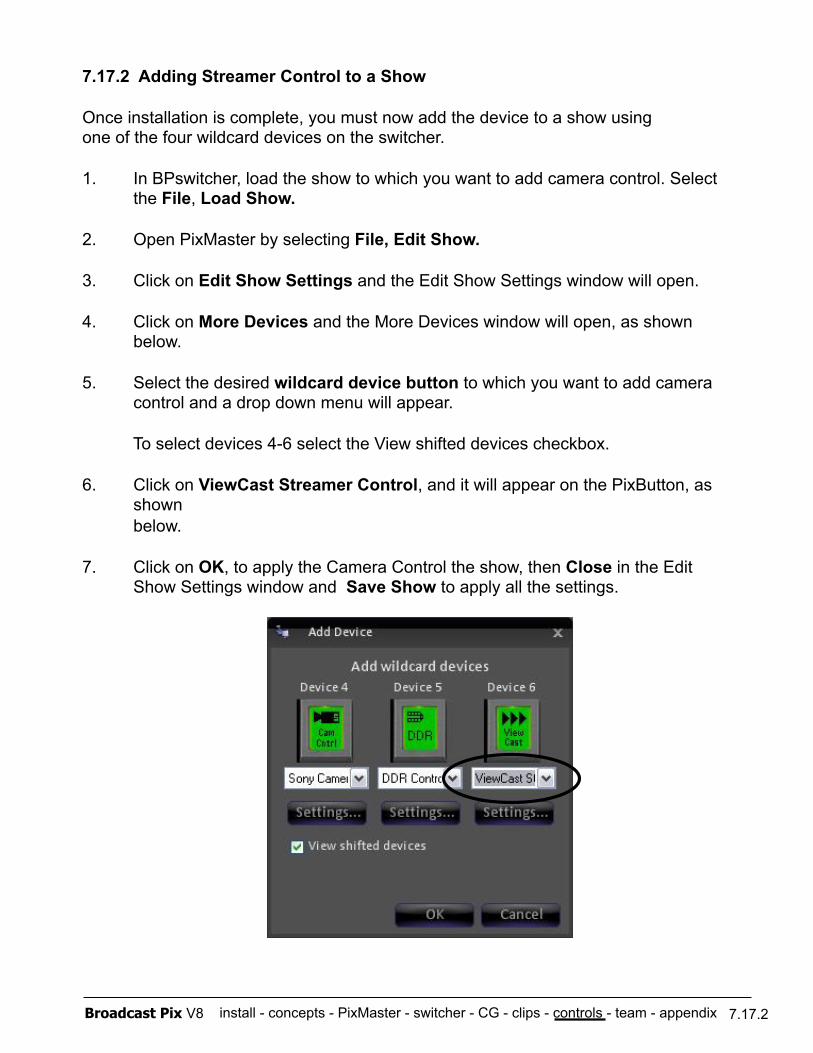
install - concepts - PixMaster - switcher - CG - clips - controls - team - appendix Broadcast Pix V8
7.17.2 Adding Streamer Control to a Show
Once installation is complete, you must now add the device to a show using one of the four wildcard devices on the switcher.
1. In BPswitcher, load the show to which you want to add camera control. Select the File, Load Show.
2. Open PixMaster by selecting File, Edit Show.
3. Click on Edit Show Settings and the Edit Show Settings window will open.
4. Click on More Devices and the More Devices window will open, as shown below.
5. Select the desired wildcard device button to which you want to add camera control and a drop down menu will appear.
To select devices 4-6 select the View shifted devices checkbox.
6. Click on ViewCast Streamer Control, and it will appear on the PixButton, as shown below.
7. Click on OK, to apply the Camera Control the show, then Close in the Edit Show Settings window and Save Show to apply all the settings.
7.17.2
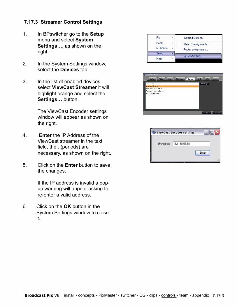
install - concepts - PixMaster - switcher - CG - clips - controls - team - appendix Broadcast Pix V8 7.17.3
7.17.3 Streamer Control Settings
1. In BPswitcher go to the Setup menu and select System Settings…, as shown on the right.
2. In the System Settings window, select the Devices tab.
3. In the list of enabled devices select ViewCast Streamer it will highlight orange and select the Settings… button.
The ViewCast Encoder settings window will appear as shown on the right.
4. Enter the IP Address of the ViewCast streamer in the text field, the . (periods) are necessary, as shown on the right.
5. Click on the Enter button to save the changes.
If the IP address is invalid a pop- up warning will appear asking to re-enter a valid address.
6. Click on the OK button in the System Settings window to close it.
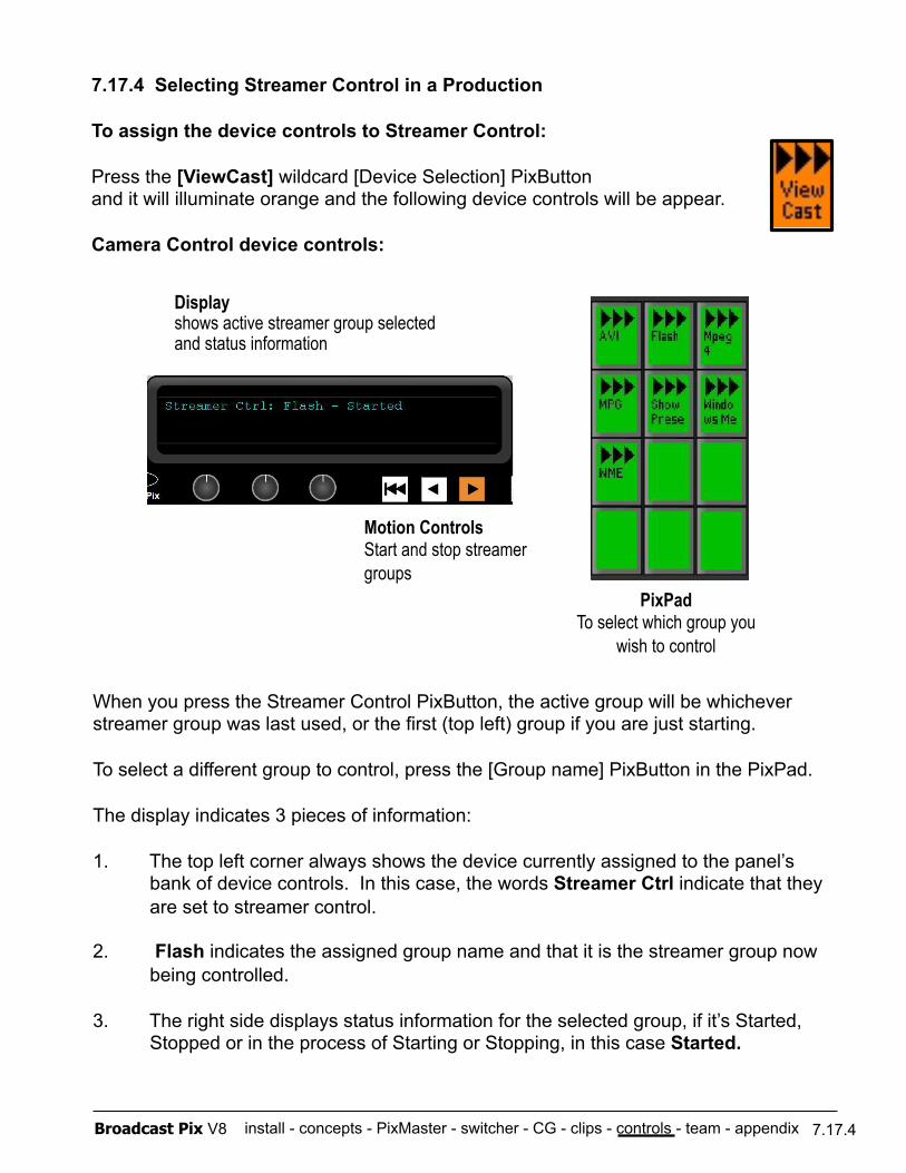
install - concepts - PixMaster - switcher - CG - clips - controls - team - appendix Broadcast Pix V8
7.17.4 Selecting Streamer Control in a Production
To assign the device controls to Streamer Control:
Press the [ViewCast] wildcard [Device Selection] PixButton and it will illuminate orange and the following device controls will be appear.
Camera Control device controls:
PixPad To select which group you
wish to control
Motion Controls Start and stop streamer groups
When you press the Streamer Control PixButton, the active group will be whichever streamer group was last used, or the first (top left) group if you are just starting.
To select a different group to control, press the [Group name] PixButton in the PixPad.
The display indicates 3 pieces of information:
1. The top left corner always shows the device currently assigned to the panel’s bank of device controls. In this case, the words Streamer Ctrl indicate that they are set to streamer control.
2. Flash indicates the assigned group name and that it is the streamer group now being controlled.
3. The right side displays status information for the selected group, if it’s Started, Stopped or in the process of Starting or Stopping, in this case Started.
Display shows active streamer group selected and status information
7.17.4
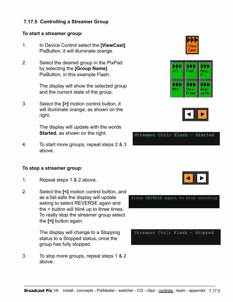
install - concepts - PixMaster - switcher - CG - clips - controls - team - appendix Broadcast Pix V8 7.17.5
7.17.5 Controlling a Streamer Group
To start a streamer group:
1. In Device Control select the [ViewCast] PixButton, it will illuminate orange.
2. Select the desired group in the PixPad by selecting the [Group Name] PixButton, in this example Flash.
The display will show the selected group and the current state of the group.
3. Select the [>] motion control button, it will illuminate orange, as shown on the right.
The display will update with the words Started, as shown on the right.
4. To start more groups, repeat steps 2 & 3 above.
To stop a streamer group:
1. Repeat steps 1 & 2 above.
2. Select the [<] motion control button, and as a fail-safe the display will update asking to select REVERSE again and the < button will blink up to three times. To really stop the streamer group select the [<] button again.
The display will change to a Stopping status to a Stopped status, once the group has fully stopped.
3. To stop more groups, repeat steps 1 & 2 above.
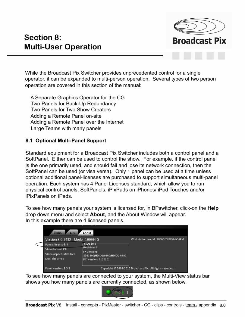
install - concepts - PixMaster - switcher - CG - clips - controls - team - appendix Broadcast Pix V8
8.1 Optional Multi-Panel Support
Standard equipment for a Broadcast Pix Switcher includes both a control panel and a SoftPanel. Either can be used to control the show. For example, if the control panel is the one primarily used, and should fail and lose its network connection, then the SoftPanel can be used (or visa versa). Only 1 panel can be used at a time unless optional additional panel-licenses are purchased to support simultaneous multi-panel operation. Each system has 4 Panel Licenses standard, which allow you to run physical control panels, SoftPanels, iPixPads on iPhones/ iPod Touches and/or iPixPanels on iPads.
To see how many panels your system is licensed for, in BPswitcher, click-on the Help drop down menu and select About, and the About Window will appear. In this example there are 4 licensed panels.
To see how many panels are connected to your system, the Multi-View status bar shows you how many panels are currently connected, as shown below.
While the Broadcast Pix Switcher provides unprecedented control for a single operator, it can be expanded to multi-person operation. Several types of two person operation are covered in this section of the manual:
A Separate Graphics Operator for the CG Two Panels for Back-Up Redundancy Two Panels for Two Show Creators Adding a Remote Panel on-site Adding a Remote Panel over the Internet Large Teams with many panels
8.0
Section 8: Multi-User Operation
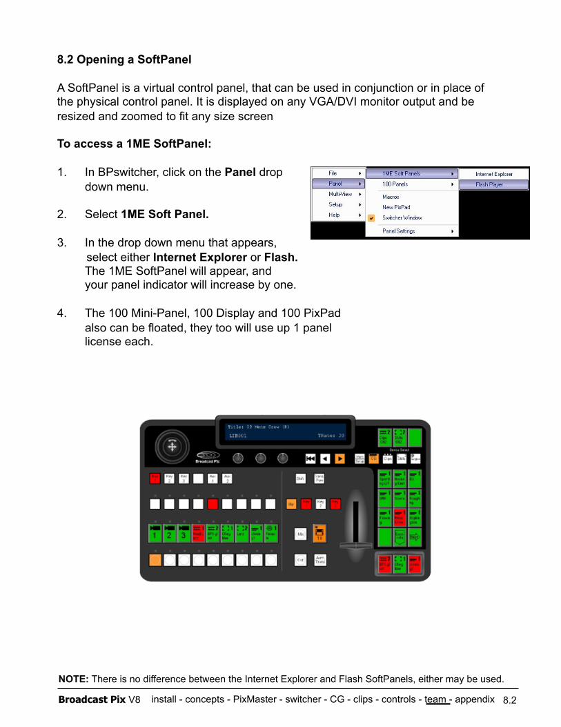
install - concepts - PixMaster - switcher - CG - clips - controls - team - appendix Broadcast Pix V8
8.2 Opening a SoftPanel
A SoftPanel is a virtual control panel, that can be used in conjunction or in place of the physical control panel. It is displayed on any VGA/DVI monitor output and be resized and zoomed to fit any size screen
To access a 1ME SoftPanel:
1. In BPswitcher, click on the Panel drop down menu.
2. Select 1ME Soft Panel.
3. In the drop down menu that appears, select either Internet Explorer or Flash.
The 1ME SoftPanel will appear, and your panel indicator will increase by one.
4. The 100 Mini-Panel, 100 Display and 100 PixPad also can be floated, they too will use up 1 panel license each.
8.2
NOTE: There is no difference between the Internet Explorer and Flash SoftPanels, either may be used.
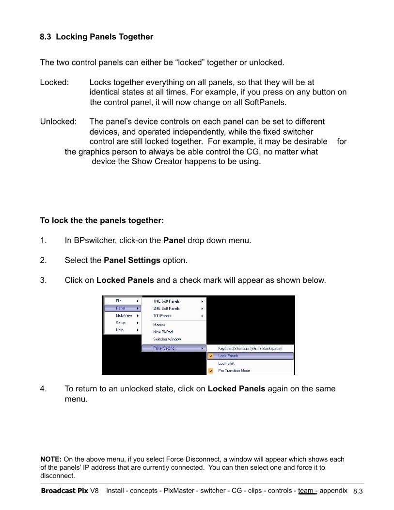
install - concepts - PixMaster - switcher - CG - clips - controls - team - appendix Broadcast Pix V8
8.3 Locking Panels Together
The two control panels can either be “locked” together or unlocked.
Locked: Locks together everything on all panels, so that they will be at identical states at all times. For example, if you press on any button on
the control panel, it will now change on all SoftPanels.
Unlocked: The panel’s device controls on each panel can be set to different devices, and operated independently, while the fixed switcher control are still locked together. For example, it may be desirable for
the graphics person to always be able control the CG, no matter what device the Show Creator happens to be using.
To lock the the panels together:
1. In BPswitcher, click-on the Panel drop down menu.
2. Select the Panel Settings option.
3. Click on Locked Panels and a check mark will appear as shown below.
4. To return to an unlocked state, click on Locked Panels again on the same menu.
8.3
NOTE: On the above menu, if you select Force Disconnect, a window will appear which shows each of the panels’ IP address that are currently connected. You can then select one and force it to disconnect.
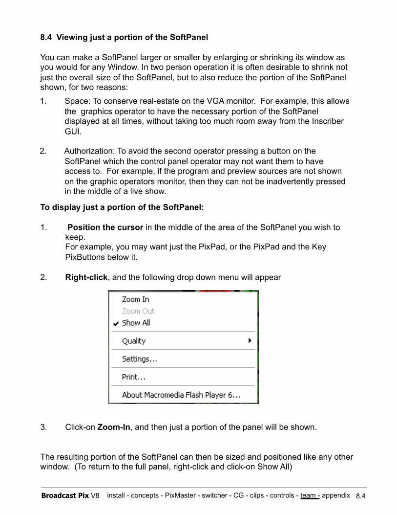
install - concepts - PixMaster - switcher - CG - clips - controls - team - appendix Broadcast Pix V8
8.4 Viewing just a portion of the SoftPanel
You can make a SoftPanel larger or smaller by enlarging or shrinking its window as you would for any Window. In two person operation it is often desirable to shrink not just the overall size of the SoftPanel, but to also reduce the portion of the SoftPanel shown, for two reasons:
To display just a portion of the SoftPanel:
1. Position the cursor in the middle of the area of the SoftPanel you wish to keep. For example, you may want just the PixPad, or the PixPad and the Key PixButtons below it.
2. Right-click, and the following drop down menu will appear
3. Click-on Zoom-In, and then just a portion of the panel will be shown.
The resulting portion of the SoftPanel can then be sized and positioned like any other window. (To return to the full panel, right-click and click-on Show All)
8.4
1. Space: To conserve real-estate on the VGA monitor. For example, this allows the graphics operator to have the necessary portion of the SoftPanel displayed at all times, without taking too much room away from the Inscriber GUI.
2. Authorization: To avoid the second operator pressing a button on the SoftPanel which the control panel operator may not want them to have access to. For example, if the program and preview sources are not shown on the graphic operators monitor, then they can not be inadvertently pressed in the middle of a live show.
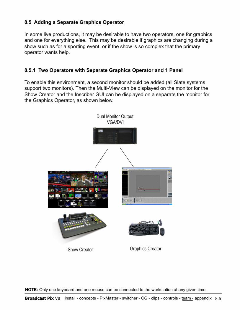
install - concepts - PixMaster - switcher - CG - clips - controls - team - appendix Broadcast Pix V8
8.5 Adding a Separate Graphics Operator
In some live productions, it may be desirable to have two operators, one for graphics and one for everything else. This may be desirable if graphics are changing during a show such as for a sporting event, or if the show is so complex that the primary operator wants help.
8.5.1 Two Operators with Separate Graphics Operator and 1 Panel
To enable this environment, a second monitor should be added (all Slate systems support two monitors). Then the Multi-View can be displayed on the monitor for the Show Creator and the Inscriber GUI can be displayed on a separate the monitor for the Graphics Operator, as shown below.
Dual Monitor Output VGA/DVI
Show Creator Graphics Creator
8.5
NOTE: Only one keyboard and one mouse can be connected to the workstation at any given time.
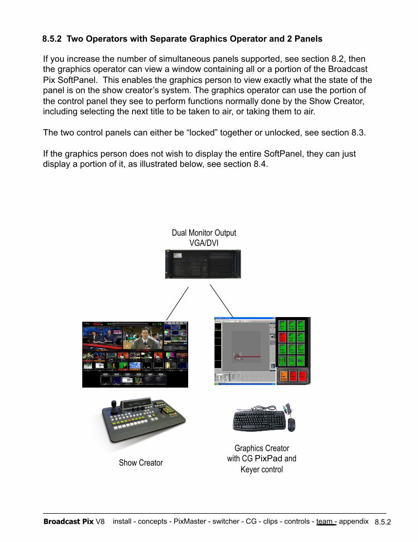
install - concepts - PixMaster - switcher - CG - clips - controls - team - appendix Broadcast Pix V8
8.5.2 Two Operators with Separate Graphics Operator and 2 Panels
Show Creator Graphics Creator
with CG PixPad and Keyer control
If you increase the number of simultaneous panels supported, see section 8.2, then the graphics operator can view a window containing all or a portion of the Broadcast Pix SoftPanel. This enables the graphics person to view exactly what the state of the panel is on the show creator’s system. The graphics operator can use the portion of the control panel they see to perform functions normally done by the Show Creator, including selecting the next title to be taken to air, or taking them to air.
The two control panels can either be “locked” together or unlocked, see section 8.3.
If the graphics person does not wish to display the entire SoftPanel, they can just display a portion of it, as illustrated below, see section 8.4.
8.5.2
Dual Monitor Output VGA/DVI
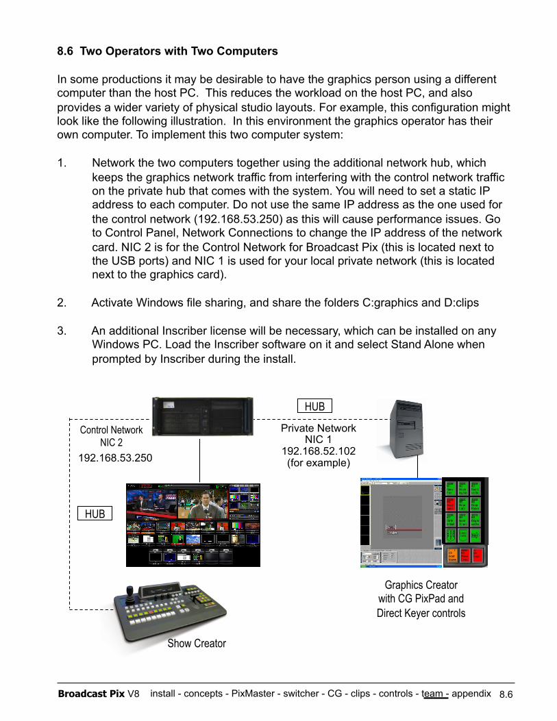
install - concepts - PixMaster - switcher - CG - clips - controls - team - appendix Broadcast Pix V8
Show Creator
HUB
8.6 Two Operators with Two Computers
In some productions it may be desirable to have the graphics person using a different computer than the host PC. This reduces the workload on the host PC, and also provides a wider variety of physical studio layouts. For example, this configuration might look like the following illustration. In this environment the graphics operator has their own computer. To implement this two computer system:
1. Network the two computers together using the additional network hub, which keeps the graphics network traffic from interfering with the control network traffic on the private hub that comes with the system. You will need to set a static IP address to each computer. Do not use the same IP address as the one used for the control network (192.168.53.250) as this will cause performance issues. Go to Control Panel, Network Connections to change the IP address of the network card. NIC 2 is for the Control Network for Broadcast Pix (this is located next to the USB ports) and NIC 1 is used for your local private network (this is located next to the graphics card).
2. Activate Windows file sharing, and share the folders C:graphics and D:clips
3. An additional Inscriber license will be necessary, which can be installed on any Windows PC. Load the Inscriber software on it and select Stand Alone when prompted by Inscriber during the install.
HUB
Graphics Creator with CG PixPad and Direct Keyer controls
Control Network NIC 2
8.6
192.168.53.250
Private Network NIC 1
192.168.52.102 (for example)
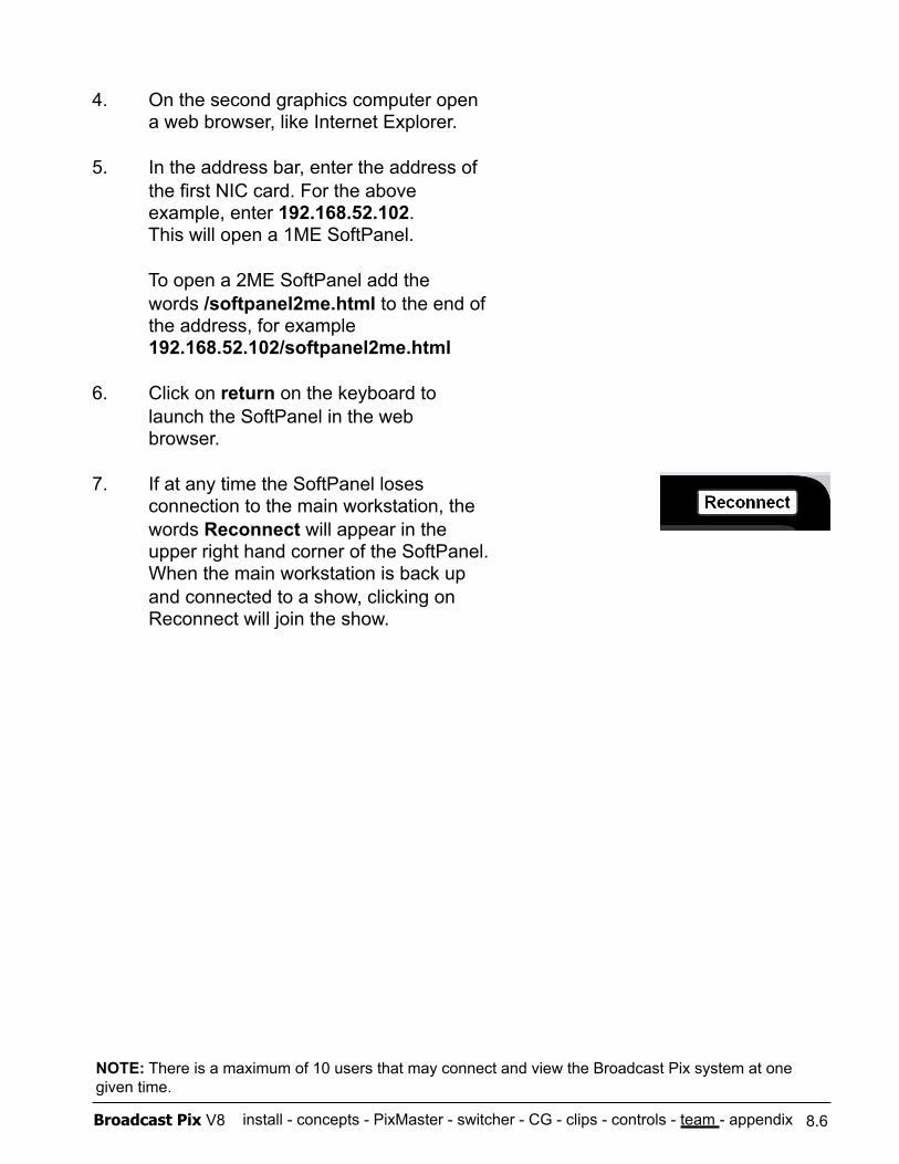
install - concepts - PixMaster - switcher - CG - clips - controls - team - appendix Broadcast Pix V8
4. On the second graphics computer open a web browser, like Internet Explorer.
5. In the address bar, enter the address of the first NIC card. For the above example, enter 192.168.52.102. This will open a 1ME SoftPanel.
To open a 2ME SoftPanel add the words /softpanel2me.html to the end of the address, for example 192.168.52.102/softpanel2me.html
6. Click on return on the keyboard to launch the SoftPanel in the web browser.
7. If at any time the SoftPanel loses connection to the main workstation, the words Reconnect will appear in the upper right hand corner of the SoftPanel. When the main workstation is back up and connected to a show, clicking on Reconnect will join the show.
8.6
NOTE: There is a maximum of 10 users that may connect and view the Broadcast Pix system at one given time.
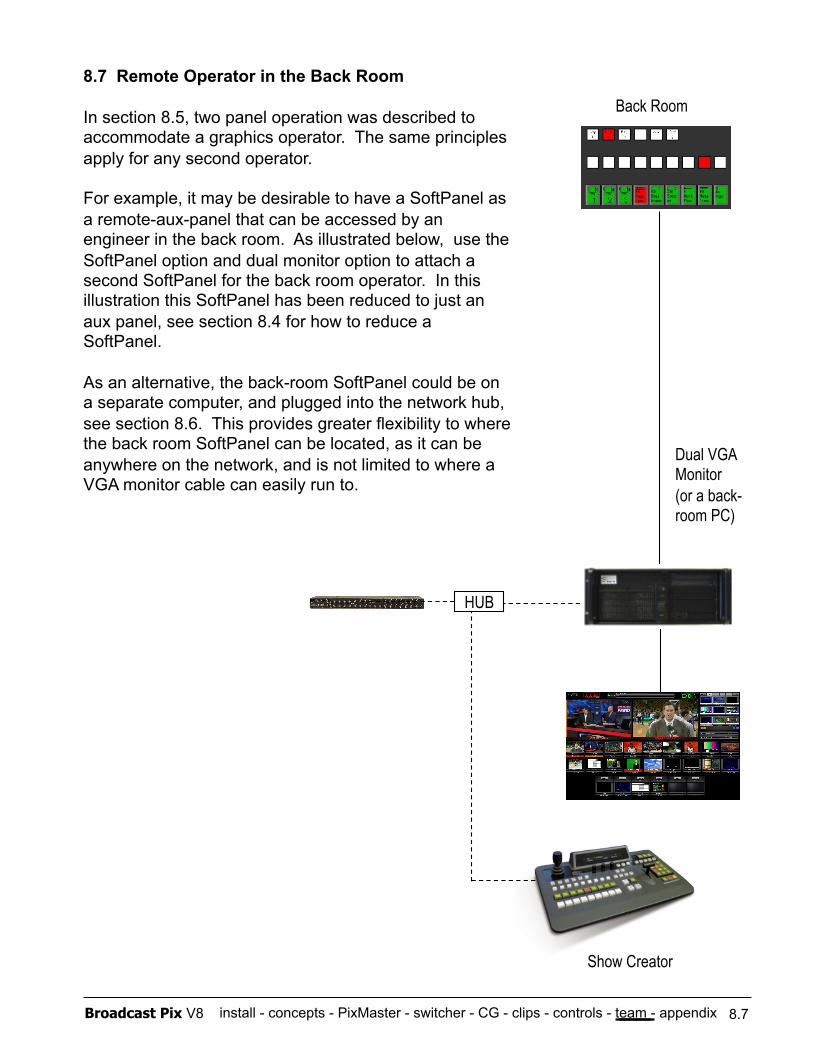
install - concepts - PixMaster - switcher - CG - clips - controls - team - appendix Broadcast Pix V8
Show Creator
HUB
8.7 Remote Operator in the Back Room
In section 8.5, two panel operation was described to accommodate a graphics operator. The same principles apply for any second operator.
For example, it may be desirable to have a SoftPanel as a remote-aux-panel that can be accessed by an engineer in the back room. As illustrated below, use the SoftPanel option and dual monitor option to attach a second SoftPanel for the back room operator. In this illustration this SoftPanel has been reduced to just an aux panel, see section 8.4 for how to reduce a SoftPanel.
As an alternative, the back-room SoftPanel could be on a separate computer, and plugged into the network hub, see section 8.6. This provides greater flexibility to where the back room SoftPanel can be located, as it can be anywhere on the network, and is not limited to where a VGA monitor cable can easily run to.
Back Room
Dual VGA Monitor (or a back-room PC)
8.7
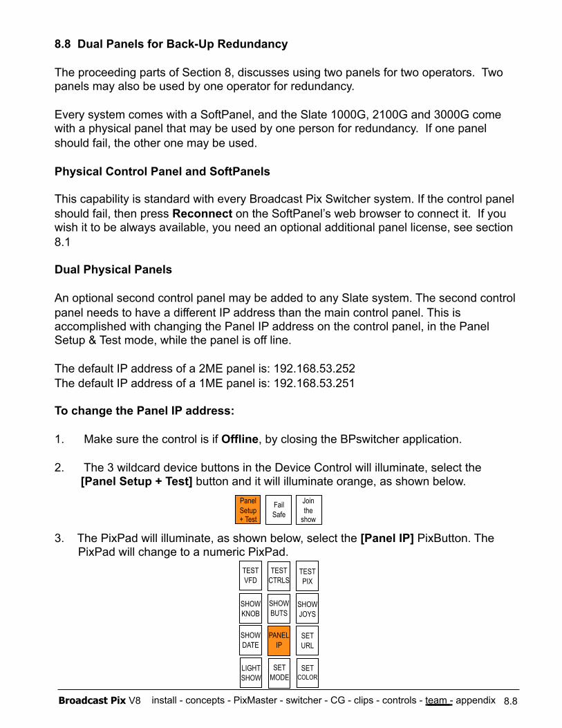
install - concepts - PixMaster - switcher - CG - clips - controls - team - appendix Broadcast Pix V8
8.8 Dual Panels for Back-Up Redundancy
The proceeding parts of Section 8, discusses using two panels for two operators. Two panels may also be used by one operator for redundancy.
Every system comes with a SoftPanel, and the Slate 1000G, 2100G and 3000G come with a physical panel that may be used by one person for redundancy. If one panel should fail, the other one may be used.
Physical Control Panel and SoftPanels
This capability is standard with every Broadcast Pix Switcher system. If the control panel should fail, then press Reconnect on the SoftPanel’s web browser to connect it. If you wish it to be always available, you need an optional additional panel license, see section 8.1
Dual Physical Panels
An optional second control panel may be added to any Slate system. The second control panel needs to have a different IP address than the main control panel. This is accomplished with changing the Panel IP address on the control panel, in the Panel Setup & Test mode, while the panel is off line.
The default IP address of a 2ME panel is: 192.168.53.252 The default IP address of a 1ME panel is: 192.168.53.251
To change the Panel IP address:
1. Make sure the control is if Offline, by closing the BPswitcher application.
2. The 3 wildcard device buttons in the Device Control will illuminate, select the [Panel Setup + Test] button and it will illuminate orange, as shown below.
3. The PixPad will illuminate, as shown below, select the [Panel IP] PixButton. The PixPad will change to a numeric PixPad.
8.8
Panel Setup + Test
Fail Safe
Join the
show
TEST VFD
TEST CTRLS
TEST PIX
SHOW KNOB
SHOW BUTS
SHOW JOYS
SHOW DATE
PANEL IP
SET URL
LIGHT SHOW
SET MODE
SET COLOR
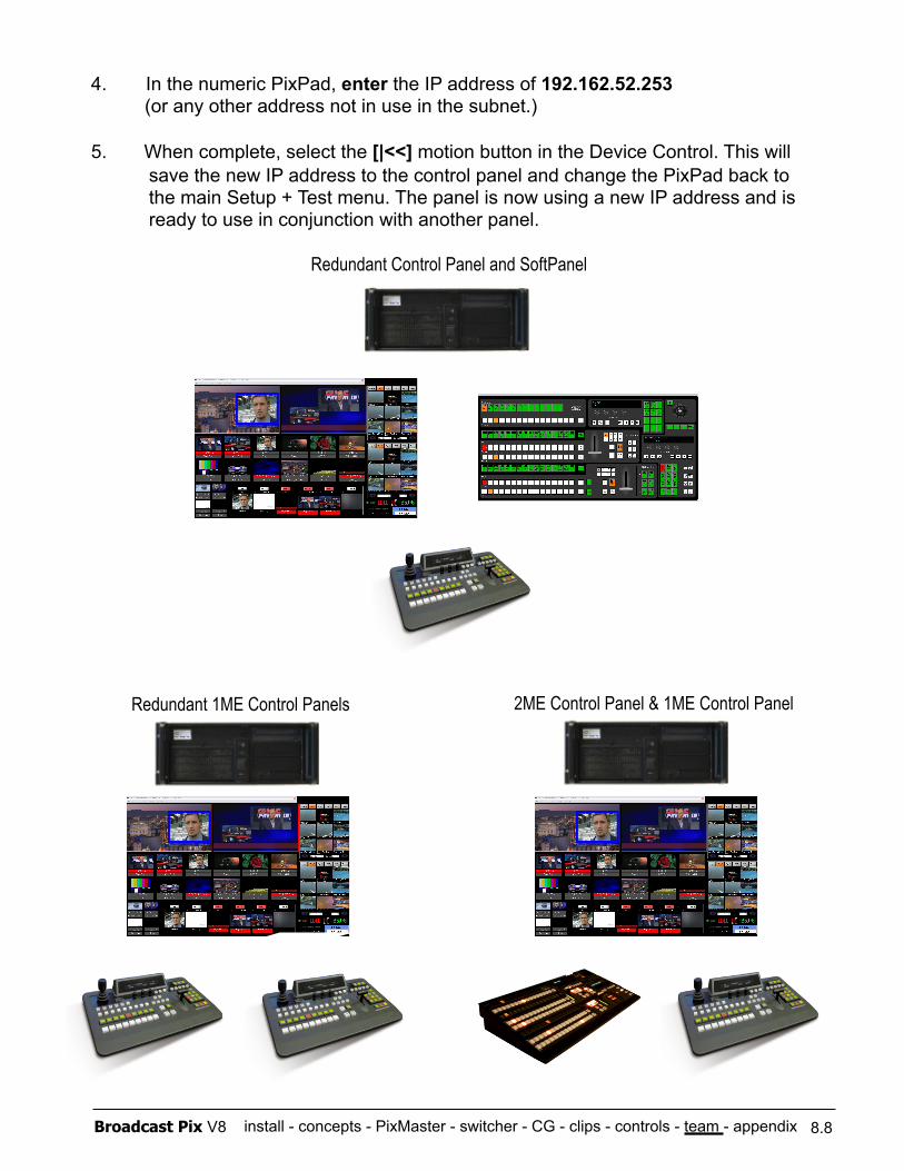
install - concepts - PixMaster - switcher - CG - clips - controls - team - appendix Broadcast Pix V8
4. In the numeric PixPad, enter the IP address of 192.162.52.253 (or any other address not in use in the subnet.)
5. When complete, select the [|<<] motion button in the Device Control. This will save the new IP address to the control panel and change the PixPad back to the main Setup + Test menu. The panel is now using a new IP address and is ready to use in conjunction with another panel.
8.8
Redundant 1ME Control Panels
Redundant Control Panel and SoftPanel
2ME Control Panel & 1ME Control Panel
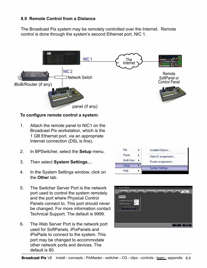
install - concepts - PixMaster - switcher - CG - clips - controls - team - appendix Broadcast Pix V8
8.9 Remote Control from a Distance
The Broadcast Pix system may be remotely controlled over the Internet. Remote control is done through the system’s second Ethernet port, NIC 1.
8.9
NIC 2
NIC 1
Remote SoftPanel or Control Panel
The Internet
To configure remote control a system:
1. Attach the remote panel to NIC1 on the Broadcast Pix workstation, which is the 1 GB Ethernet port, via an appropriate Internet connection (DSL is fine).
2. In BPSwitcher, select the Setup menu.
3. Then select System Settings…
4. In the System Settings window, click on the Other tab.
5. The Switcher Server Port is the network port used to control the system remotely and the port where Physical Control Panels connect to. This port should never be changed. For more information contact Technical Support. The default is 9999.
6. The Web Server Port is the network port used for SoftPanels, iPixPanels and iPixPads to connect to the system. This port may be changed to accommodate other network ports and devices. The default is 80.
Network Switch iBoB/Router (if any)
panel (if any)
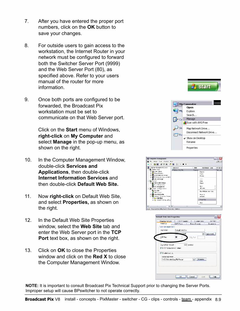
install - concepts - PixMaster - switcher - CG - clips - controls - team - appendix Broadcast Pix V8 8.9
7. After you have entered the proper port numbers, click on the OK button to save your changes.
8. For outside users to gain access to the workstation, the Internet Router in your network must be configured to forward both the Switcher Server Port (9999) and the Web Server Port (80), as specified above. Refer to your users manual of the router for more information.
9. Once both ports are configured to be forwarded, the Broadcast Pix workstation must be set to communicate on that Web Server port.
Click on the Start menu of Windows, right-click on My Computer and select Manage in the pop-up menu, as shown on the right.
10. In the Computer Management Window, double-click Services and Applications, then double-click Internet Information Services and then double-click Default Web Site.
11. Now right-click on Default Web Site, and select Properties, as shown on the right.
12. In the Default Web Site Properties window, select the Web Site tab and enter the Web Server port in the TCP Port text box, as shown on the right.
13. Click on OK to close the Properties window and click on the Red X to close the Computer Management Window.
NOTE: It is important to consult Broadcast Pix Technical Support prior to changing the Server Ports. Improper setup will cause BPswitcher to not operate correctly.
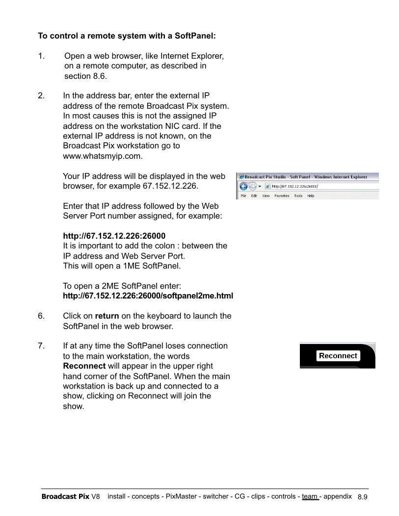
install - concepts - PixMaster - switcher - CG - clips - controls - team - appendix Broadcast Pix V8 8.9
To control a remote system with a SoftPanel:
1. Open a web browser, like Internet Explorer, on a remote computer, as described in section 8.6.
2. In the address bar, enter the external IP address of the remote Broadcast Pix system. In most causes this is not the assigned IP address on the workstation NIC card. If the external IP address is not known, on the Broadcast Pix workstation go to www.whatsmyip.com.
Your IP address will be displayed in the web browser, for example 67.152.12.226.
Enter that IP address followed by the Web Server Port number assigned, for example:
http://67.152.12.226:26000 It is important to add the colon : between the IP address and Web Server Port. This will open a 1ME SoftPanel.
To open a 2ME SoftPanel enter: http://67.152.12.226:26000/softpanel2me.html
6. Click on return on the keyboard to launch the SoftPanel in the web browser.
7. If at any time the SoftPanel loses connection to the main workstation, the words Reconnect will appear in the upper right hand corner of the SoftPanel. When the main workstation is back up and connected to a show, clicking on Reconnect will join the show.
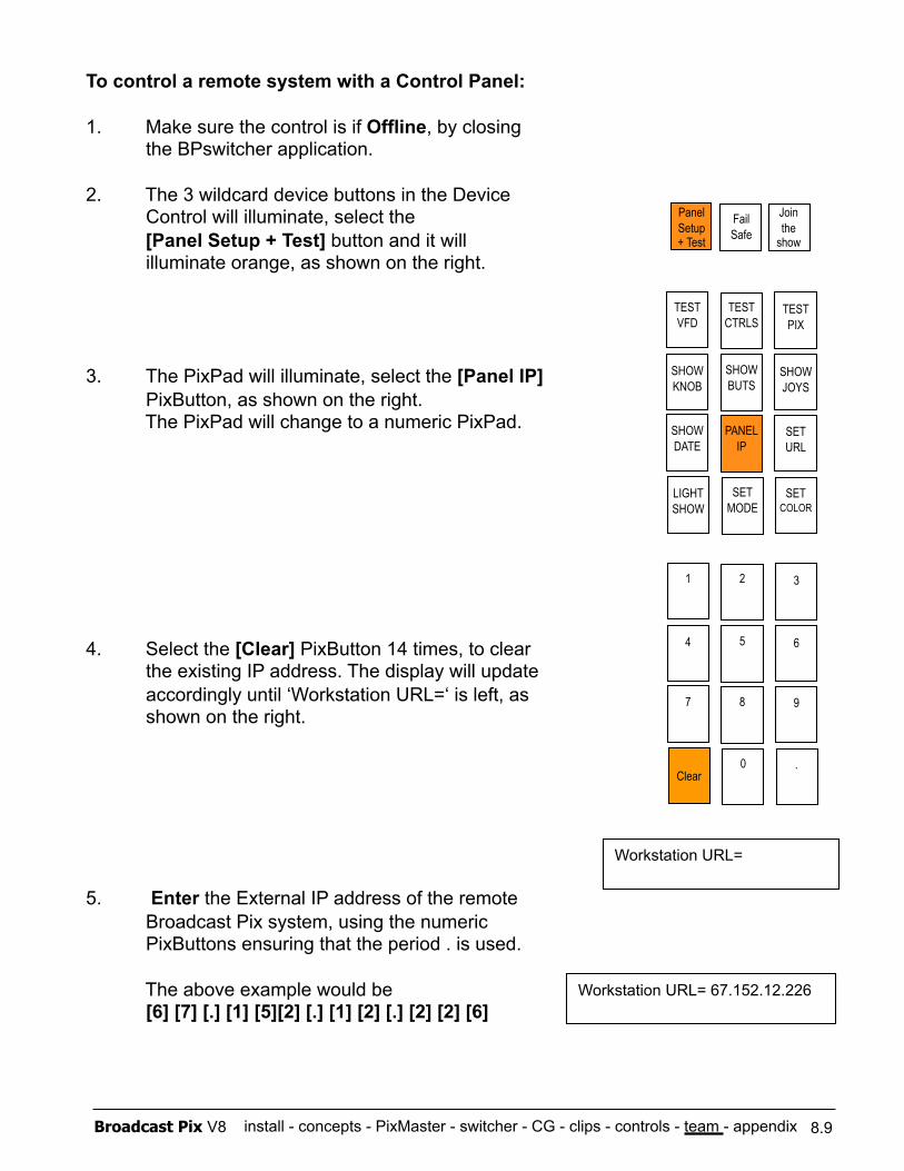
install - concepts - PixMaster - switcher - CG - clips - controls - team - appendix Broadcast Pix V8 8.9
To control a remote system with a Control Panel:
1. Make sure the control is if Offline, by closing the BPswitcher application.
2. The 3 wildcard device buttons in the Device Control will illuminate, select the
[Panel Setup + Test] button and it will illuminate orange, as shown on the right.
3. The PixPad will illuminate, select the [Panel IP] PixButton, as shown on the right.
The PixPad will change to a numeric PixPad.
4. Select the [Clear] PixButton 14 times, to clear the existing IP address. The display will update accordingly until ‘Workstation URL=‘ is left, as shown on the right.
5. Enter the External IP address of the remote Broadcast Pix system, using the numeric PixButtons ensuring that the period . is used.
The above example would be [6] [7] [.] [1] [5][2] [.] [1] [2] [.] [2] [2] [6]
TEST VFD
TEST CTRLS
TEST PIX
SHOW KNOB
SHOW BUTS
SHOW JOYS
SHOW DATE
PANEL IP
SET URL
LIGHT SHOW
SET MODE
SET COLOR
1 2 3
4 5 6
7 8 9
Clear 0 .
Workstation URL=
Workstation URL= 67.152.12.226
Panel Setup + Test
Fail Safe
Join the
show
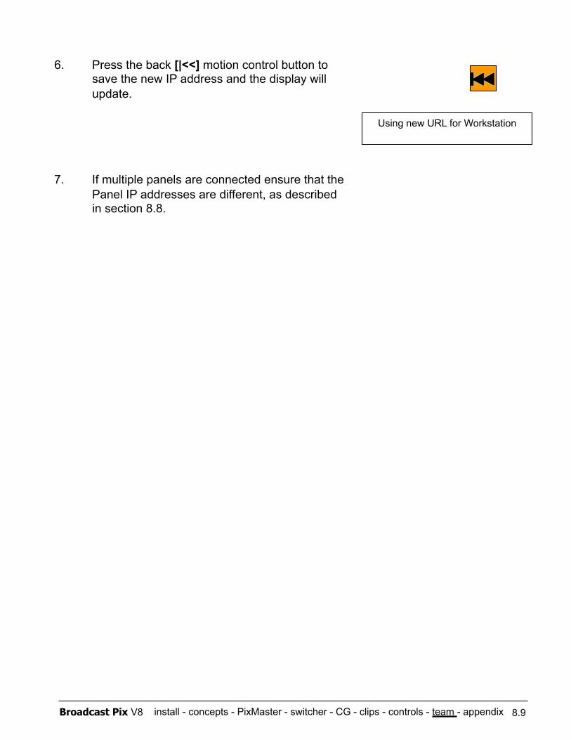
install - concepts - PixMaster - switcher - CG - clips - controls - team - appendix Broadcast Pix V8 8.9
6. Press the back [|<<] motion control button to save the new IP address and the display will update.
7. If multiple panels are connected ensure that the Panel IP addresses are different, as described in section 8.8.
Using new URL for Workstation
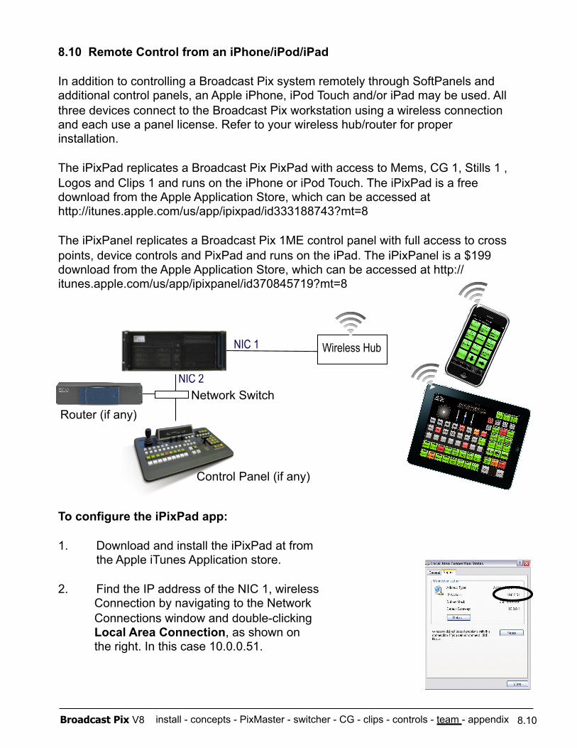
install - concepts - PixMaster - switcher - CG - clips - controls - team - appendix Broadcast Pix V8
8.10 Remote Control from an iPhone/iPod/iPad
In addition to controlling a Broadcast Pix system remotely through SoftPanels and additional control panels, an Apple iPhone, iPod Touch and/or iPad may be used. All three devices connect to the Broadcast Pix workstation using a wireless connection and each use a panel license. Refer to your wireless hub/router for proper installation.
The iPixPad replicates a Broadcast Pix PixPad with access to Mems, CG 1, Stills 1 , Logos and Clips 1 and runs on the iPhone or iPod Touch. The iPixPad is a free download from the Apple Application Store, which can be accessed at http://itunes.apple.com/us/app/ipixpad/id333188743?mt=8
The iPixPanel replicates a Broadcast Pix 1ME control panel with full access to cross points, device controls and PixPad and runs on the iPad. The iPixPanel is a $199 download from the Apple Application Store, which can be accessed at http://itunes.apple.com/us/app/ipixpanel/id370845719?mt=8
To configure the iPixPad app:
1. Download and install the iPixPad at from the Apple iTunes Application store.
2. Find the IP address of the NIC 1, wireless Connection by navigating to the Network Connections window and double-clicking Local Area Connection, as shown on the right. In this case 10.0.0.51.
8.10
NIC 2
NIC 1 Wireless Hub
Network Switch Router (if any)
Control Panel (if any)
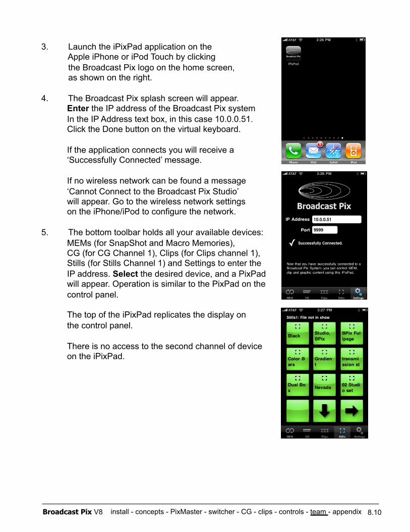
install - concepts - PixMaster - switcher - CG - clips - controls - team - appendix Broadcast Pix V8
3. Launch the iPixPad application on the Apple iPhone or iPod Touch by clicking the Broadcast Pix logo on the home screen, as shown on the right.
4. The Broadcast Pix splash screen will appear. Enter the IP address of the Broadcast Pix system In the IP Address text box, in this case 10.0.0.51. Click the Done button on the virtual keyboard.
If the application connects you will receive a ‘Successfully Connected’ message.
If no wireless network can be found a message ‘Cannot Connect to the Broadcast Pix Studio’ will appear. Go to the wireless network settings on the iPhone/iPod to configure the network.
5. The bottom toolbar holds all your available devices: MEMs (for SnapShot and Macro Memories), CG (for CG Channel 1), Clips (for Clips channel 1), Stills (for Stills Channel 1) and Settings to enter the IP address. Select the desired device, and a PixPad will appear. Operation is similar to the PixPad on the control panel.
The top of the iPixPad replicates the display on the control panel.
There is no access to the second channel of device on the iPixPad.
8.10
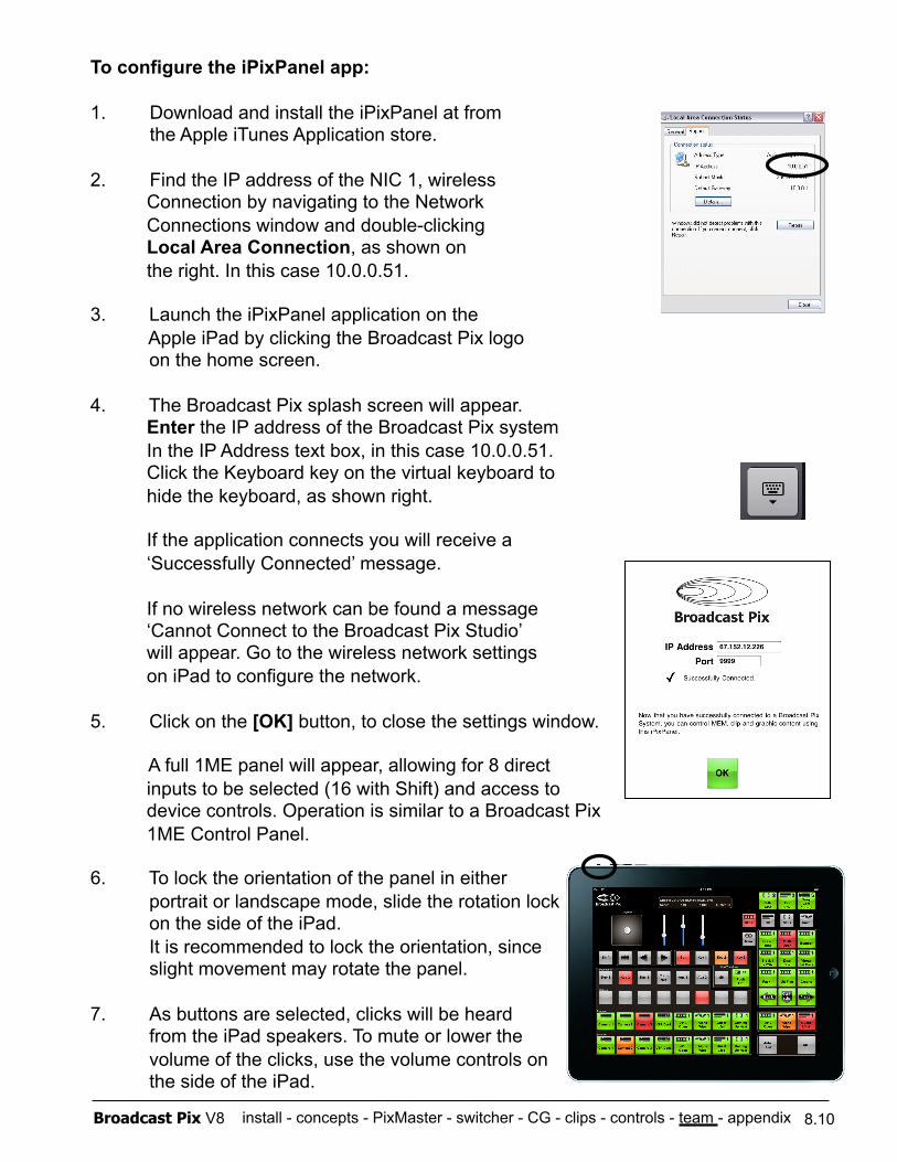
install - concepts - PixMaster - switcher - CG - clips - controls - team - appendix Broadcast Pix V8
To configure the iPixPanel app:
1. Download and install the iPixPanel at from the Apple iTunes Application store.
2. Find the IP address of the NIC 1, wireless Connection by navigating to the Network Connections window and double-clicking Local Area Connection, as shown on the right. In this case 10.0.0.51.
3. Launch the iPixPanel application on the Apple iPad by clicking the Broadcast Pix logo on the home screen.
4. The Broadcast Pix splash screen will appear. Enter the IP address of the Broadcast Pix system In the IP Address text box, in this case 10.0.0.51. Click the Keyboard key on the virtual keyboard to hide the keyboard, as shown right.
If the application connects you will receive a ‘Successfully Connected’ message.
If no wireless network can be found a message ‘Cannot Connect to the Broadcast Pix Studio’ will appear. Go to the wireless network settings on iPad to configure the network.
5. Click on the [OK] button, to close the settings window.
A full 1ME panel will appear, allowing for 8 direct inputs to be selected (16 with Shift) and access to device controls. Operation is similar to a Broadcast Pix 1ME Control Panel.
6. To lock the orientation of the panel in either portrait or landscape mode, slide the rotation lock on the side of the iPad. It is recommended to lock the orientation, since slight movement may rotate the panel.
7. As buttons are selected, clicks will be heard from the iPad speakers. To mute or lower the volume of the clicks, use the volume controls on the side of the iPad.
8.10
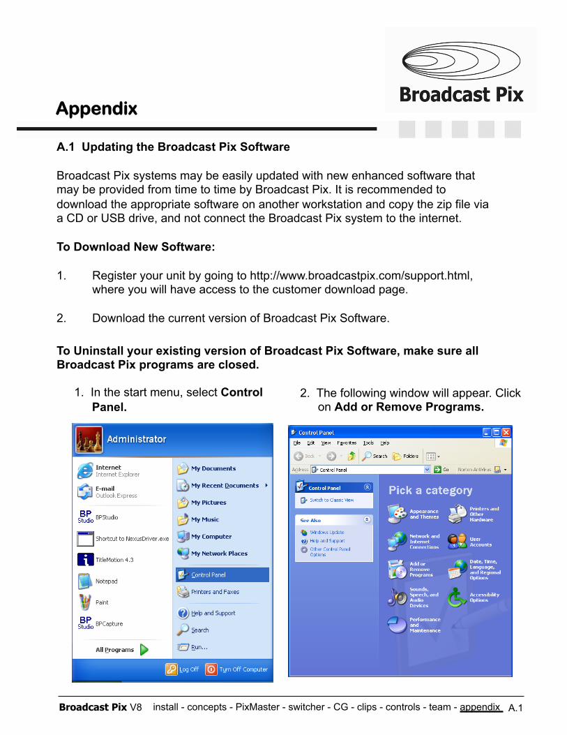
install - concepts - PixMaster - switcher - CG - clips - controls - team - appendix Broadcast Pix V8 A.1
A.1 Updating the Broadcast Pix Software
Broadcast Pix systems may be easily updated with new enhanced software that may be provided from time to time by Broadcast Pix. It is recommended to download the appropriate software on another workstation and copy the zip file via a CD or USB drive, and not connect the Broadcast Pix system to the internet.
To Download New Software:
1. Register your unit by going to http://www.broadcastpix.com/support.html, where you will have access to the customer download page.
2. Download the current version of Broadcast Pix Software.
To Uninstall your existing version of Broadcast Pix Software, make sure all Broadcast Pix programs are closed.
2. The following window will appear. Click on Add or Remove Programs.
1. In the start menu, select Control Panel.
Appendix
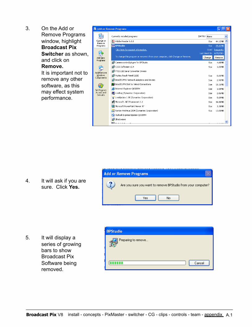
install - concepts - PixMaster - switcher - CG - clips - controls - team - appendix Broadcast Pix V8 A.1
3. On the Add or Remove Programs window, highlight Broadcast Pix Switcher as shown, and click on Remove. It is important not to remove any other software, as this may effect system performance.
4. It will ask if you are sure. Click Yes.
5. It will display a series of growing bars to show Broadcast Pix Software being removed.
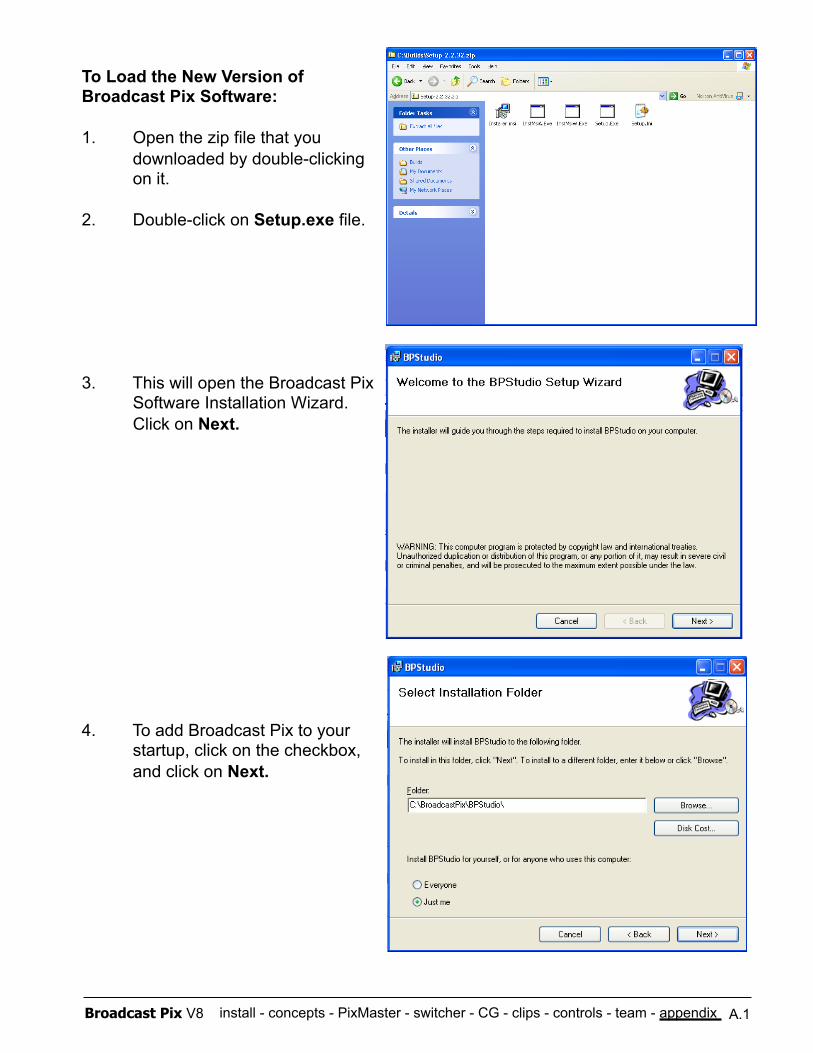
install - concepts - PixMaster - switcher - CG - clips - controls - team - appendix Broadcast Pix V8 A.1
To Load the New Version of Broadcast Pix Software:
1. Open the zip file that you downloaded by double-clicking on it.
2. Double-click on Setup.exe file.
3. This will open the Broadcast Pix Software Installation Wizard. Click on Next.
4. To add Broadcast Pix to your startup, click on the checkbox, and click on Next.
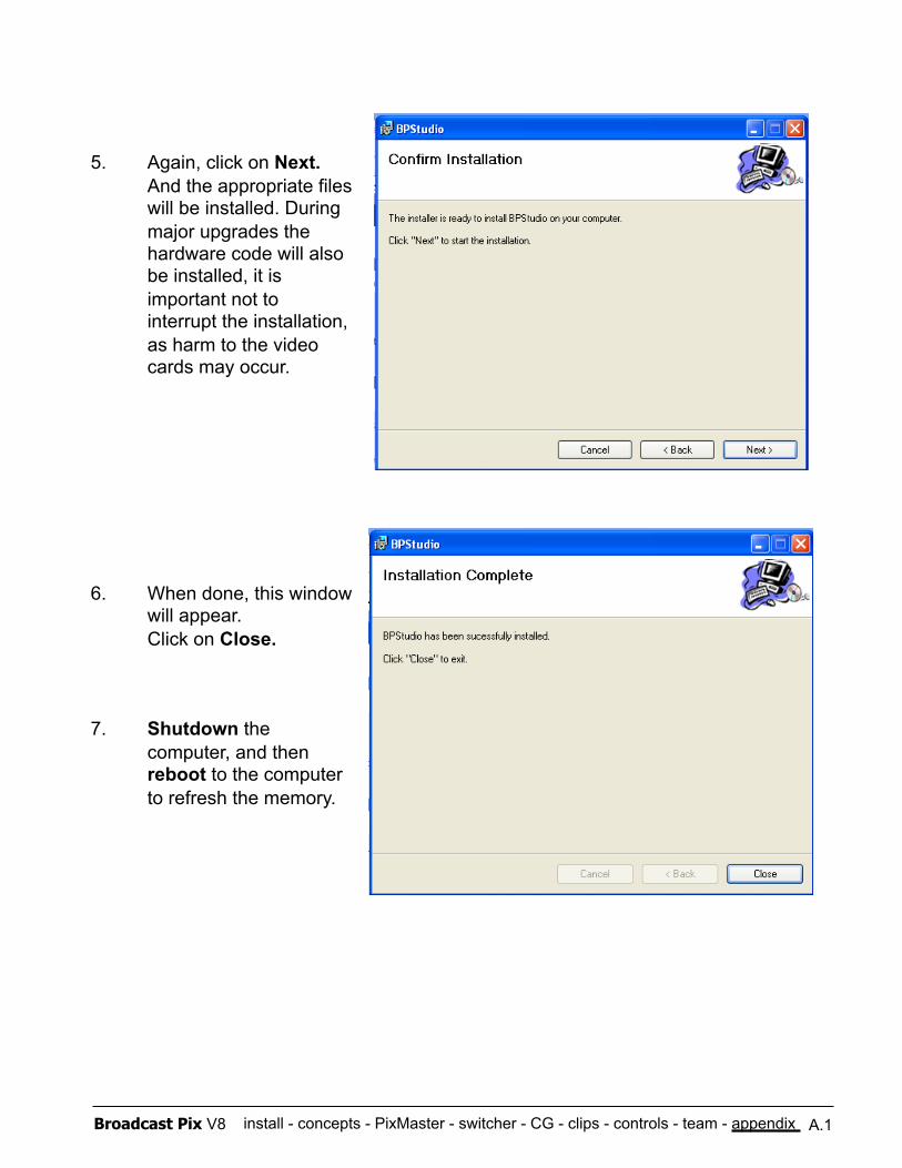
install - concepts - PixMaster - switcher - CG - clips - controls - team - appendix Broadcast Pix V8 A.1
5. Again, click on Next. And the appropriate files will be installed. During major upgrades the hardware code will also be installed, it is important not to interrupt the installation, as harm to the video cards may occur.
6. When done, this window will appear. Click on Close.
7. Shutdown the computer, and then reboot to the computer to refresh the memory.
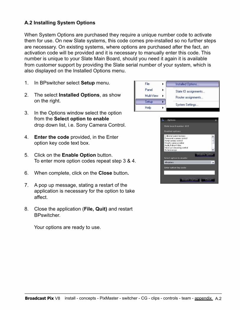
install - concepts - PixMaster - switcher - CG - clips - controls - team - appendix Broadcast Pix V8 A.2
A.2 Installing System Options
When System Options are purchased they require a unique number code to activate them for use. On new Slate systems, this code comes pre-installed so no further steps are necessary. On existing systems, where options are purchased after the fact, an activation code will be provided and it is necessary to manually enter this code. This number is unique to your Slate Main Board, should you need it again it is available from customer support by providing the Slate serial number of your system, which is also displayed on the Installed Options menu.
1. In BPswitcher select Setup menu.
2. The select Installed Options, as show on the right.
3. In the Options window select the option from the Select option to enable drop down list, i.e. Sony Camera Control.
4. Enter the code provided, in the Enter option key code text box.
5. Click on the Enable Option button. To enter more option codes repeat step 3 & 4.
6. When complete, click on the Close button.
7. A pop up message, stating a restart of the application is necessary for the option to take affect.
8. Close the application (File, Quit) and restart BPswitcher.
Your options are ready to use.
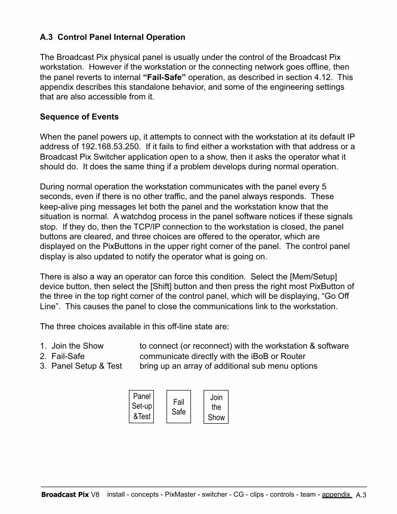
install - concepts - PixMaster - switcher - CG - clips - controls - team - appendix Broadcast Pix V8
A.3 Control Panel Internal Operation
The Broadcast Pix physical panel is usually under the control of the Broadcast Pix workstation. However if the workstation or the connecting network goes offline, then the panel reverts to internal “Fail-Safe” operation, as described in section 4.12. This appendix describes this standalone behavior, and some of the engineering settings that are also accessible from it.
Sequence of Events
When the panel powers up, it attempts to connect with the workstation at its default IP address of 192.168.53.250. If it fails to find either a workstation with that address or a Broadcast Pix Switcher application open to a show, then it asks the operator what it should do. It does the same thing if a problem develops during normal operation.
During normal operation the workstation communicates with the panel every 5 seconds, even if there is no other traffic, and the panel always responds. These keep-alive ping messages let both the panel and the workstation know that the situation is normal. A watchdog process in the panel software notices if these signals stop. If they do, then the TCP/IP connection to the workstation is closed, the panel buttons are cleared, and three choices are offered to the operator, which are displayed on the PixButtons in the upper right corner of the panel. The control panel display is also updated to notify the operator what is going on.
There is also a way an operator can force this condition. Select the [Mem/Setup] device button, then select the [Shift] button and then press the right most PixButton of the three in the top right corner of the control panel, which will be displaying, “Go Off Line”. This causes the panel to close the communications link to the workstation.
The three choices available in this off-line state are:
1. Join the Show to connect (or reconnect) with the workstation & software 2. Fail-Safe communicate directly with the iBoB or Router 3. Panel Setup & Test bring up an array of additional sub menu options
A.3
Fail Safe
Join the
Show
Panel Set-up &Test
install - concepts - PixMaster - switcher - CG - clips - controls - team - appendix Broadcast Pix V8
Join the Show
Whenever a panel is not connected to a workstation, it continuously attempts reconnection. If successful, the Join the Show button changes from green to orange.
Pressing this button when it is orange, immediately connects to the current running show on the workstation.
Pressing this button when it is green, causes the panel to reboot itself. This can be useful to recover from an unusual condition.
Fail-Safe
By selecting this option the operator commands the panel to control the Break Out Box (iBoB) or the router directly using the serial connection. The program and preview rows of buttons are activated, and the program row PixButtons are labeled appropriately. Inputs 1 through 8 are labeled 1 through 8, indicating the input channels of the iBoB or router. On a Slate 2100G inputs 9 through 16 are labeled RTR 1 through RTR 8, indicating cascaded router inputs 1 through 8. Inputs 17 and 18 are labeled Show Prog. and Show Prev., indicating their use as the connections from the Broadcast Pix workstation running the current show. On a Slate 3000G inputs inputs 9 through 14 are labeled 9 thought 14 indicating input channels on the router and inputs 15 and 16 are labeled Show Prog. and Show Prev., indicating their use as the connections from the Broadcast Pix workstation running the current show. The Cut button is also illuminated, indicating that it can be used to perform cuts between program and preview.
When entering the Fail-Safe mode, program and preview are automatically connected to the input that the most recently run show defined as the fail-safe source. If no source was so identified, then program is set to Show Prog. and preview is set to Show Prev. For this fall back mode of operation to work most effectively, be sure that the video source connected to fail-safe source is the one that you want to go on air when Fail-safe mode is entered.
Two other PixButtons are illuminated while in fail-safe mode. These are the Join The Show and the Panel Setup & Test PixButtons. These allow selection of these two modes, as described in the next page.
When in Fail-Safe mode, if the operator wants to switch back to the show running on the workstation, first check on the state of the workstation by calling up on preview the workstation’s program output by selecting [Show Prog.] on preview. If it looks good, a seamless reconnection to the show can be achieved by first selecting [Show Prog.] on the program row (or the [Cut] button) before pressing the [Join The Show] button.
A.3
install - concepts - PixMaster - switcher - CG - clips - controls - team - appendix Broadcast Pix V8
Panel Setup & Test
Selecting this option opens a sub menu on the PixPad PixButtons. It also sets up a button labeled “Select Panel Mode” on the effects PixButtons, which instantly terminates any of the sub modes and returns the panel to this Panel Setup & Test mode. The sub menus are:
Turn Off/On Sleep turns off or forces on sleep mode (see below)
Test Vfd displays and scrolls all possible characters through the display Test Ctrls allows testing and interpretation of all controls Test Pix allows testing of each Pix button display Show Knobs displays the raw data from the three rotary encoders Show Buts displays the raw data from all the pushbuttons Show Joys displays the raw data from the lever and joystick Show Date displays the version date of the panel software Panel IP allows editing of the TCP/IP address of the panel Set URL allows editing of the TCP/IP address of the workstation Light Show cycles through all the lights in an eye-catching manner Set Mode allows selection of which router is connected (see below) Set Color a 2ME function to allow brightness/contrast adjust for PixButtons
Sleep
Normally the panel falls asleep after 30 minutes of inactivity. While asleep all panel buttons are extinguished, and a single dot scrolls through the display. A press of any button awakens the panel, but is otherwise ignored. If sleeping is not desired, press Turn Off Sleep to disable it The second line of the display will now say, “Sleep has been disabled.” When sleep is disabled the Turn Off Sleep button changes to Force To Sleep and if pressed, re-enables sleeping and forces the panel asleep immediately.
Panel Mode
The control panel can control three external routers: the iBoB, a 16x16 and a 32x32 router. In doing so, the control panel needs to be told which router is being used. On new systems this setting is already set, but on existing units this setting needs to be changed. If the control panel version date is 2/26/2008 or later, then this setting is enabled, if not contact technical support about upgrading your control panel’s software. To check which version is installed see the above Panel Setup & Test menu and select Show Date. When the Panel Mode button is selected, this activates the backwards and forwards motion controls as well as the display. Select the appropriate router either Targa mode, iBoB mode, 16x Router mode or 32x Router mode. Select the Select Panel Mode PixButton when the correct mode has been selected.
A.3
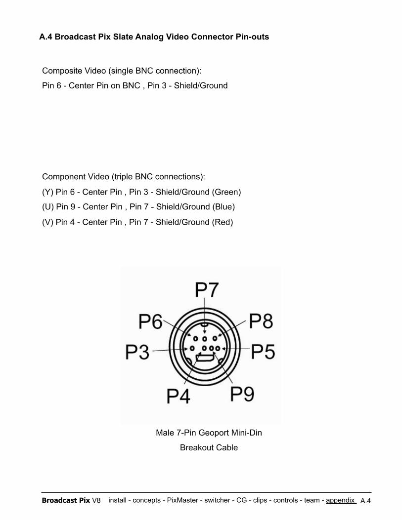
install - concepts - PixMaster - switcher - CG - clips - controls - team - appendix Broadcast Pix V8
A.4 Broadcast Pix Slate Analog Video Connector Pin-outs
A.4
Composite Video (single BNC connection):
Pin 6 - Center Pin on BNC , Pin 3 - Shield/Ground
Component Video (triple BNC connections):
(Y) Pin 6 - Center Pin , Pin 3 - Shield/Ground (Green)
(U) Pin 9 - Center Pin , Pin 7 - Shield/Ground (Blue)
(V) Pin 4 - Center Pin , Pin 7 - Shield/Ground (Red)
Male 7-Pin Geoport Mini-Din
Breakout Cable
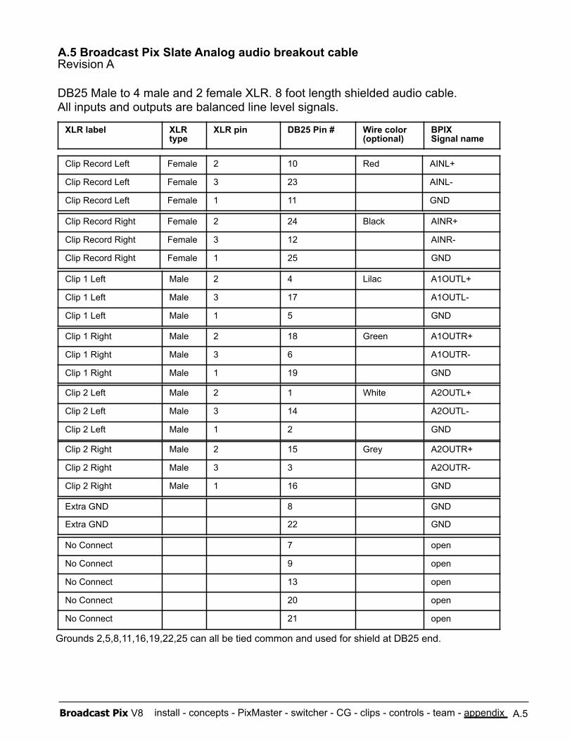
install - concepts - PixMaster - switcher - CG - clips - controls - team - appendix Broadcast Pix V8
Revision A
DB25 Male to 4 male and 2 female XLR. 8 foot length shielded audio cable. All inputs and outputs are balanced line level signals.
XLR label XLR type
XLR pin DB25 Pin # Wire color (optional)
BPIX Signal name
Clip Record Left Female 2 10 Red AINL+
Clip Record Left Female 3 23 AINL-
Clip Record Left Female 1 11 GND
Clip Record Right Female 2 24 Black AINR+
Clip Record Right Female 3 12 AINR-
Clip Record Right Female 1 25 GND
Clip 1 Left Male 2 4 Lilac A1OUTL+
Clip 1 Left Male 3 17 A1OUTL-
Clip 1 Left Male 1 5 GND
Clip 1 Right Male 2 18 Green A1OUTR+
Clip 1 Right Male 3 6 A1OUTR-
Clip 1 Right Male 1 19 GND
Clip 2 Left Male 2 1 White A2OUTL+
Clip 2 Left Male 3 14 A2OUTL-
Clip 2 Left Male 1 2 GND
Clip 2 Right Male 2 15 Grey A2OUTR+
Clip 2 Right Male 3 3 A2OUTR-
Clip 2 Right Male 1 16 GND
Extra GND 8 GND
Extra GND 22 GND
No Connect 7 open
No Connect 9 open
No Connect 13 open
No Connect 20 open
No Connect 21 open
Grounds 2,5,8,11,16,19,22,25 can all be tied common and used for shield at DB25 end.
A.5 Broadcast Pix Slate Analog audio breakout cable
A.5
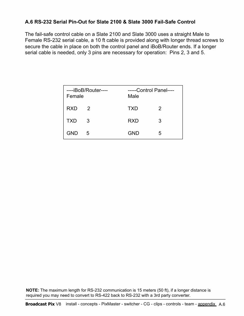
install - concepts - PixMaster - switcher - CG - clips - controls - team - appendix Broadcast Pix V8
A.6 RS-232 Serial Pin-Out for Slate 2100 & Slate 3000 Fail-Safe Control
The fail-safe control cable on a Slate 2100 and Slate 3000 uses a straight Male to Female RS-232 serial cable, a 10 ft cable is provided along with longer thread screws to secure the cable in place on both the control panel and iBoB/Router ends. If a longer serial cable is needed, only 3 pins are necessary for operation: Pins 2, 3 and 5.
A.6
NOTE: The maximum length for RS-232 communication is 15 meters (50 ft), if a longer distance is required you may need to convert to RS-422 back to RS-232 with a 3rd party converter.
----iBoB/Router---- -----Control Panel---- Female Male
RXD 2 TXD 2
TXD 3 RXD 3
GND 5 GND 5
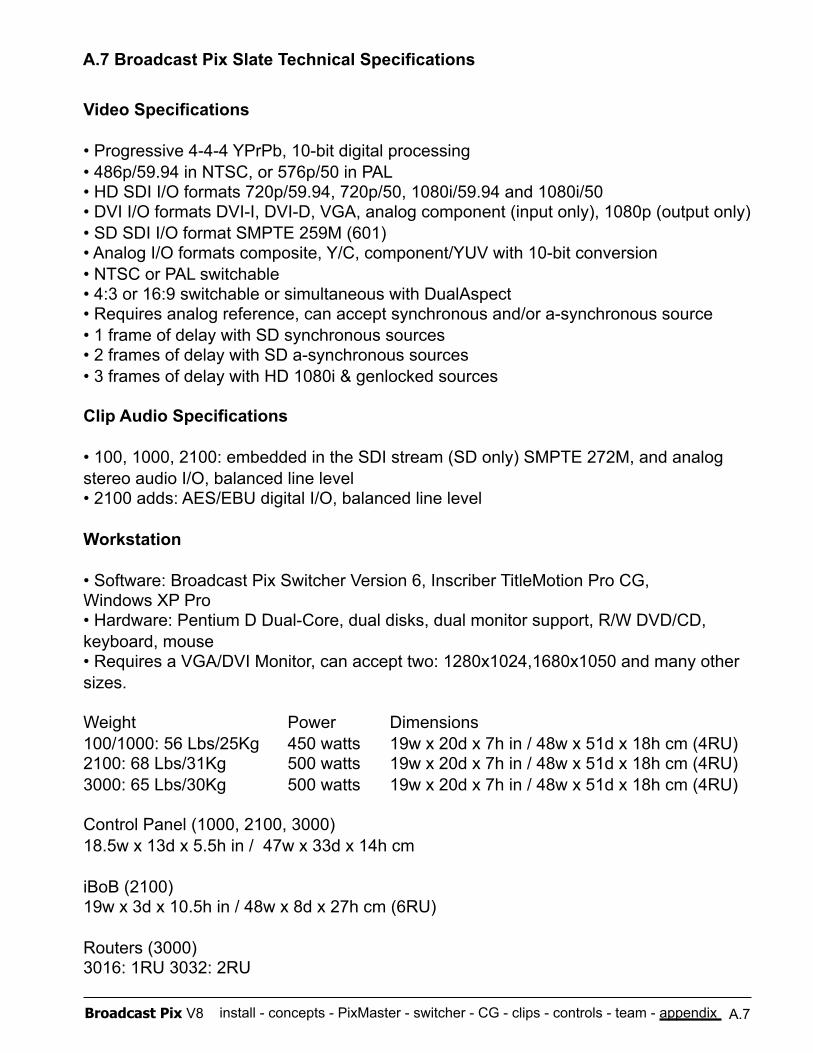
install - concepts - PixMaster - switcher - CG - clips - controls - team - appendix Broadcast Pix V8
Video Specifications
• Progressive 4-4-4 YPrPb, 10-bit digital processing • 486p/59.94 in NTSC, or 576p/50 in PAL • HD SDI I/O formats 720p/59.94, 720p/50, 1080i/59.94 and 1080i/50 • DVI I/O formats DVI-I, DVI-D, VGA, analog component (input only), 1080p (output only) • SD SDI I/O format SMPTE 259M (601) • Analog I/O formats composite, Y/C, component/YUV with 10-bit conversion • NTSC or PAL switchable • 4:3 or 16:9 switchable or simultaneous with DualAspect • Requires analog reference, can accept synchronous and/or a-synchronous source • 1 frame of delay with SD synchronous sources • 2 frames of delay with SD a-synchronous sources • 3 frames of delay with HD 1080i & genlocked sources
Clip Audio Specifications
• 100, 1000, 2100: embedded in the SDI stream (SD only) SMPTE 272M, and analog stereo audio I/O, balanced line level • 2100 adds: AES/EBU digital I/O, balanced line level
Workstation
• Software: Broadcast Pix Switcher Version 6, Inscriber TitleMotion Pro CG, Windows XP Pro • Hardware: Pentium D Dual-Core, dual disks, dual monitor support, R/W DVD/CD, keyboard, mouse • Requires a VGA/DVI Monitor, can accept two: 1280x1024,1680x1050 and many other sizes.
Weight Power Dimensions 100/1000: 56 Lbs/25Kg 450 watts 19w x 20d x 7h in / 48w x 51d x 18h cm (4RU) 2100: 68 Lbs/31Kg 500 watts 19w x 20d x 7h in / 48w x 51d x 18h cm (4RU) 3000: 65 Lbs/30Kg 500 watts 19w x 20d x 7h in / 48w x 51d x 18h cm (4RU)
Control Panel (1000, 2100, 3000) 18.5w x 13d x 5.5h in / 47w x 33d x 14h cm
iBoB (2100) 19w x 3d x 10.5h in / 48w x 8d x 27h cm (6RU)
Routers (3000) 3016: 1RU 3032: 2RU
A.7 Broadcast Pix Slate Technical Specifications
A.7
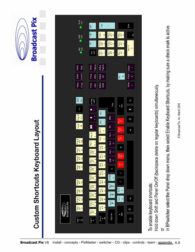
install - concepts - PixMaster - switcher - CG - clips - controls - team - appendix Broadcast Pix V8 A.8
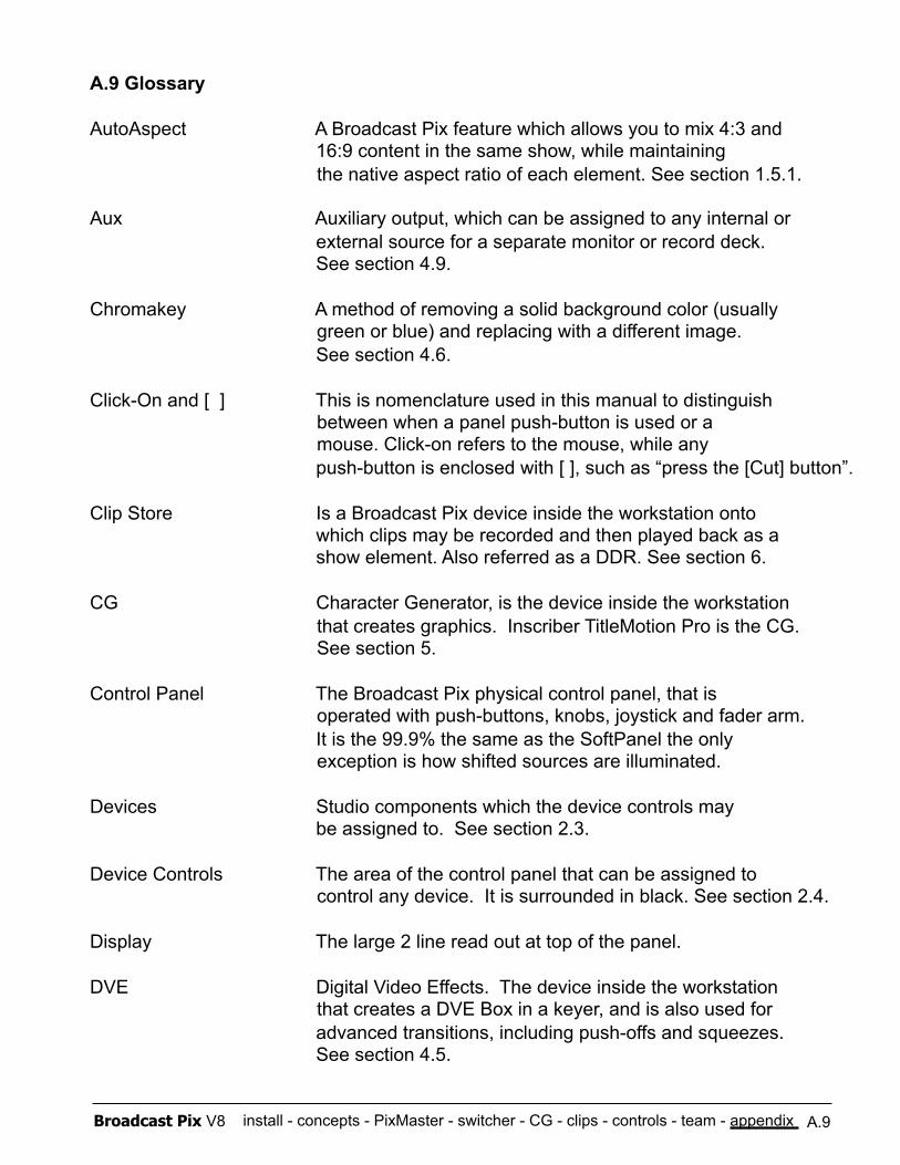
install - concepts - PixMaster - switcher - CG - clips - controls - team - appendix Broadcast Pix V8
A.9 Glossary
AutoAspect A Broadcast Pix feature which allows you to mix 4:3 and 16:9 content in the same show, while maintaining
the native aspect ratio of each element. See section 1.5.1.
Aux Auxiliary output, which can be assigned to any internal or external source for a separate monitor or record deck. See section 4.9.
Chromakey A method of removing a solid background color (usually green or blue) and replacing with a different image.
See section 4.6.
Click-On and [ ] This is nomenclature used in this manual to distinguish between when a panel push-button is used or a mouse. Click-on refers to the mouse, while any
push-button is enclosed with [ ], such as “press the [Cut] button”.
Clip Store Is a Broadcast Pix device inside the workstation onto which clips may be recorded and then played back as a
show element. Also referred as a DDR. See section 6.
CG Character Generator, is the device inside the workstation that creates graphics. Inscriber TitleMotion Pro is the CG. See section 5.
Control Panel The Broadcast Pix physical control panel, that is operated with push-buttons, knobs, joystick and fader arm.
It is the 99.9% the same as the SoftPanel the only exception is how shifted sources are illuminated.
Devices Studio components which the device controls may be assigned to. See section 2.3.
Device Controls The area of the control panel that can be assigned to control any device. It is surrounded in black. See section 2.4.
Display The large 2 line read out at top of the panel.
DVE Digital Video Effects. The device inside the workstation that creates a DVE Box in a keyer, and is also used for
advanced transitions, including push-offs and squeezes. See section 4.5.
A.9
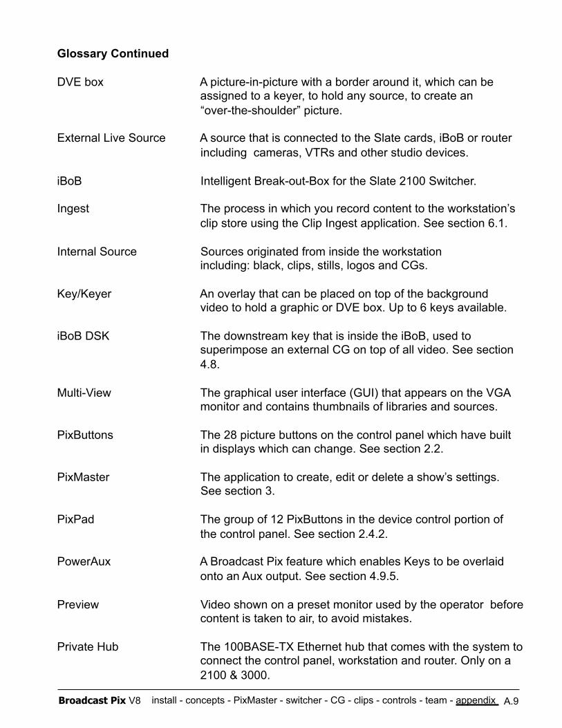
install - concepts - PixMaster - switcher - CG - clips - controls - team - appendix Broadcast Pix V8
Glossary Continued
DVE box A picture-in-picture with a border around it, which can be assigned to a keyer, to hold any source, to create an “over-the-shoulder” picture.
External Live Source A source that is connected to the Slate cards, iBoB or router including cameras, VTRs and other studio devices.
iBoB Intelligent Break-out-Box for the Slate 2100 Switcher.
Ingest The process in which you record content to the workstation’s clip store using the Clip Ingest application. See section 6.1.
Internal Source Sources originated from inside the workstation including: black, clips, stills, logos and CGs.
Key/Keyer An overlay that can be placed on top of the background video to hold a graphic or DVE box. Up to 6 keys available.
iBoB DSK The downstream key that is inside the iBoB, used to superimpose an external CG on top of all video. See section 4.8.
Multi-View The graphical user interface (GUI) that appears on the VGA monitor and contains thumbnails of libraries and sources.
PixButtons The 28 picture buttons on the control panel which have built in displays which can change. See section 2.2.
PixMaster The application to create, edit or delete a show’s settings. See section 3.
PixPad The group of 12 PixButtons in the device control portion of the control panel. See section 2.4.2.
PowerAux A Broadcast Pix feature which enables Keys to be overlaid onto an Aux output. See section 4.9.5.
Preview Video shown on a preset monitor used by the operator before content is taken to air, to avoid mistakes.
Private Hub The 100BASE-TX Ethernet hub that comes with the system to connect the control panel, workstation and router. Only on a 2100 & 3000.
A.9
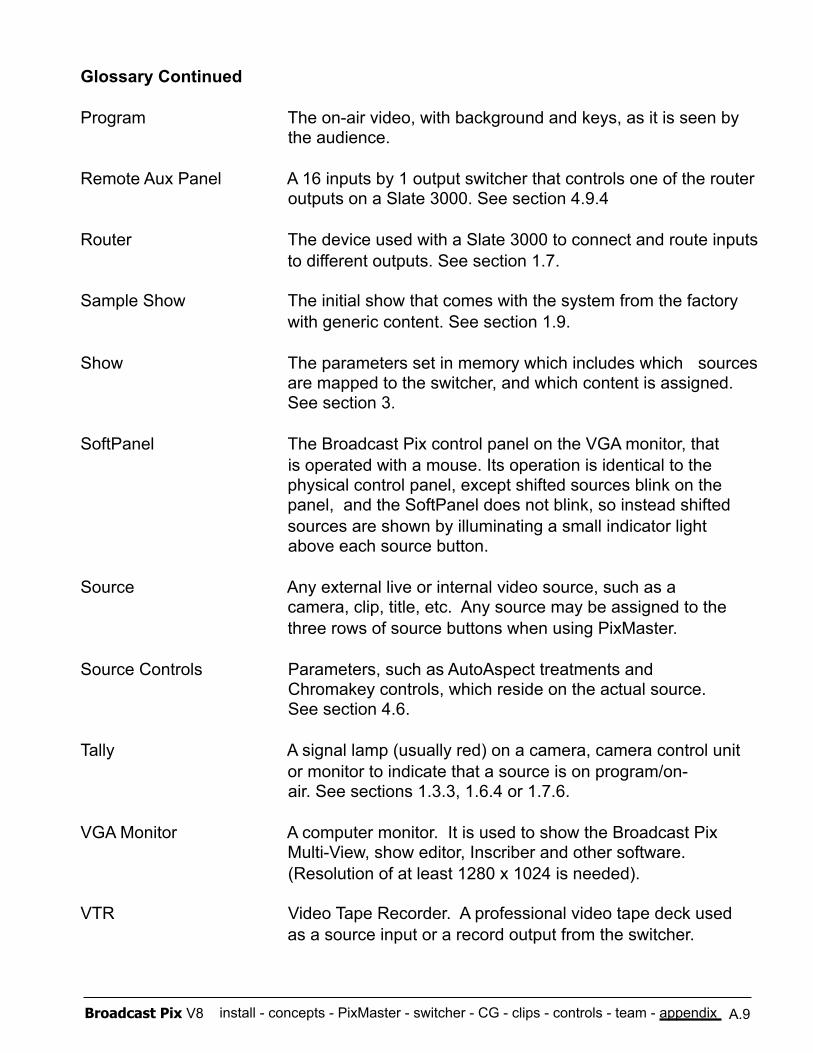
install - concepts - PixMaster - switcher - CG - clips - controls - team - appendix Broadcast Pix V8
Glossary Continued
Program The on-air video, with background and keys, as it is seen by the audience.
Remote Aux Panel A 16 inputs by 1 output switcher that controls one of the router outputs on a Slate 3000. See section 4.9.4
Router The device used with a Slate 3000 to connect and route inputs to different outputs. See section 1.7.
Sample Show The initial show that comes with the system from the factory with generic content. See section 1.9.
Show The parameters set in memory which includes which sources are mapped to the switcher, and which content is assigned. See section 3.
SoftPanel The Broadcast Pix control panel on the VGA monitor, that is operated with a mouse. Its operation is identical to the physical control panel, except shifted sources blink on the panel, and the SoftPanel does not blink, so instead shifted sources are shown by illuminating a small indicator light above each source button.
Source Any external live or internal video source, such as a camera, clip, title, etc. Any source may be assigned to the three rows of source buttons when using PixMaster.
Source Controls Parameters, such as AutoAspect treatments and Chromakey controls, which reside on the actual source. See section 4.6.
Tally A signal lamp (usually red) on a camera, camera control unit or monitor to indicate that a source is on program/on- air. See sections 1.3.3, 1.6.4 or 1.7.6.
VGA Monitor A computer monitor. It is used to show the Broadcast Pix Multi-View, show editor, Inscriber and other software. (Resolution of at least 1280 x 1024 is needed).
VTR Video Tape Recorder. A professional video tape deck used as a source input or a record output from the switcher.
A.9

install - concepts - PixMaster - switcher - CG - clips - controls - team - appendix Broadcast Pix V8
A.10 Broadcast Pix Contact Information:
Toll Free: +1-866-914-9484
Phone: +1-978-600-1100
Technical Support: +1-978-600-1098
Fax: +1-978-663-2811
Website: www.broadcastpix.com
Register on-line at www.broadcastpix.com/support.html for access to the latest software downloads and support information.
Support E-mail: [email protected]
Mailing Address: 3 Federal Street Billerica, Massachusetts 01821
USA
Broadcast Pix welcomes suggestions to this manual, please send to [email protected]
A.10
© 2010 Copyright Broadcast Pix, Inc. Broadcast Pix, Slate, iBoB, PixButtons, PixMaster, PixPad, iPixPad, iPixPanel, AutoAspect, and SoftPanel are trademarks of Broadcast Pix, Inc. Other trademarks are owned by their respective companies.

install - concepts - PixMaster - switcher - CG - clips - controls - team - appendix Broadcast Pix V8
Notes