bq76200 datasheet - ti.com · 470 nf bq76200 chg nc cp_en chg_en bat vddcp pmon_en dsg_en pchg_en...
TRANSCRIPT
470 nF
bq76200CHG
NC
CP_EN
CHG_EN
BAT
VDDCP
PMON_EN
DSG_EN
PCHG_EN
NC
PACKDIV
PCHG
NC
DSG
PACK
VSS
From AFE or
MCU
1 M
Ra
To ADC
10 M 10 M
Rb
PACK-
PACK+
100
0.01 µF
100
0.01 µF
Product
Folder
Sample &Buy
Technical
Documents
Tools &
Software
Support &Community
bq76200SLUSC16 –NOVEMBER 2015
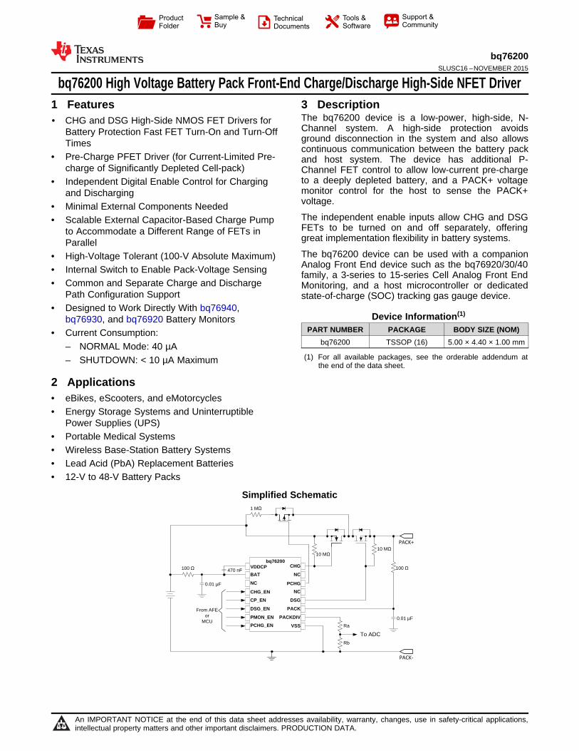
bq76200 High Voltage Battery Pack Front-End Charge/Discharge High-Side NFET Driver1 Features 3 Description
The bq76200 device is a low-power, high-side, N-1• CHG and DSG High-Side NMOS FET Drivers for
Channel system. A high-side protection avoidsBattery Protection Fast FET Turn-On and Turn-Offground disconnection in the system and also allowsTimes continuous communication between the battery pack
• Pre-Charge PFET Driver (for Current-Limited Pre- and host system. The device has additional P-charge of Significantly Depleted Cell-pack) Channel FET control to allow low-current pre-charge
to a deeply depleted battery, and a PACK+ voltage• Independent Digital Enable Control for Chargingmonitor control for the host to sense the PACK+and Dischargingvoltage.• Minimal External Components NeededThe independent enable inputs allow CHG and DSG• Scalable External Capacitor-Based Charge PumpFETs to be turned on and off separately, offeringto Accommodate a Different Range of FETs ingreat implementation flexibility in battery systems.ParallelThe bq76200 device can be used with a companion• High-Voltage Tolerant (100-V Absolute Maximum)Analog Front End device such as the bq76920/30/40• Internal Switch to Enable Pack-Voltage Sensing family, a 3-series to 15-series Cell Analog Front End
• Common and Separate Charge and Discharge Monitoring, and a host microcontroller or dedicatedPath Configuration Support state-of-charge (SOC) tracking gas gauge device.
• Designed to Work Directly With bq76940,Device Information(1)
bq76930, and bq76920 Battery MonitorsPART NUMBER PACKAGE BODY SIZE (NOM)• Current Consumption:
bq76200 TSSOP (16) 5.00 × 4.40 × 1.00 mm– NORMAL Mode: 40 µA(1) For all available packages, see the orderable addendum at– SHUTDOWN: < 10 µA Maximum the end of the data sheet.
2 Applications• eBikes, eScooters, and eMotorcycles• Energy Storage Systems and Uninterruptible
Power Supplies (UPS)• Portable Medical Systems• Wireless Base-Station Battery Systems• Lead Acid (PbA) Replacement Batteries• 12-V to 48-V Battery Packs
Simplified Schematic
1
An IMPORTANT NOTICE at the end of this data sheet addresses availability, warranty, changes, use in safety-critical applications,intellectual property matters and other important disclaimers. PRODUCTION DATA.

bq76200SLUSC16 –NOVEMBER 2015 www.ti.com
Table of Contents7.3 Feature Description................................................... 91 Features .................................................................. 17.4 Device Functional Modes........................................ 112 Applications ........................................................... 1
8 Application and Implementation ........................ 123 Description ............................................................. 18.1 Application Information............................................ 124 Revision History..................................................... 28.2 Typical Applications ................................................ 175 Pin Configuration and Functions ......................... 3
9 Power Supply Recommendations ...................... 196 Specifications......................................................... 410 Layout................................................................... 196.1 Absolute Maximum Ratings ...................................... 4
10.1 Layout Guidelines ................................................. 196.2 ESD Ratings.............................................................. 410.2 Layout Example .................................................... 196.3 Recommended Operating Conditions....................... 4
11 Device and Documentation Support ................. 216.4 Thermal Information .................................................. 411.1 Documentation Support ........................................ 216.5 Electrical Characteristics........................................... 511.2 Community Resources.......................................... 216.6 Timing Requirements ................................................ 611.3 Trademarks ........................................................... 216.7 Typical Characteristics ............................................. 711.4 Electrostatic Discharge Caution............................ 217 Detailed Description .............................................. 811.5 Glossary ................................................................ 217.1 Overview ................................................................... 8
12 Mechanical, Packaging, and Orderable7.2 Functional Block Diagram ......................................... 9Information ........................................................... 21
4 Revision History
DATE REVISION NOTESNovember 2015 * Initial Release
2 Submit Documentation Feedback Copyright © 2015, Texas Instruments Incorporated
Product Folder Links: bq76200

1
2
3
4
5
6
7
8 9
10
11
12
13
14
15
16
CHG
NC
CP_EN
CHG_EN
BAT
VDDCP
PMON_EN
DSG_EN
PCHG_EN
NC
PACKDIV
PCHG
NC
DSG
PACK
VSS
bq76200www.ti.com SLUSC16 –NOVEMBER 2015
5 Pin Configuration and Functions
PW Package16-pin TSSOP
Top View
Pin FunctionsPIN TYPE (1)
DESCRIPTIONNAME NO. I/OBAT 2 P Top of battery stack
CHG (2) 16 O Gate drive for charge FETCHG_EN (3) 4 I Charge FET enableCP_EN (3) 5 I Charge pump enable (internally logic ORed with CHG_EN and DSG_EN
signals)DSG (2) 12 O Gate drive for discharge FET
DSG_EN (3) 6 I Discharge FET enableNC 3, 13, 15 — No connect. Leave the pin floating
PACK 11 P Analog input from PACK+ terminalPACKDIV (2) 10 O PACK voltage after internal switch (connect to MCU ADC via resistor divider).
PCHG (2) 14 O Gate drive for pre-charge FETPCHG_EN (3) 8 I Pre-charge FET enablePMON_EN (3) 7 I Pack monitor enable (allows connection of internal switch between PACK
and PACKDIV)VDDCP 1 O Charge pump output. Connect a capacitor to BAT pin. Do not load this pin.
VSS 9 P Ground reference
(1) P = Power Connection, O = Digital Output, AI = Analog Input, I = Digital Input, I/OD = Digital Input/Output(2) Leave the pin float if function is not used.(3) Recommended to connect the pin to ground if function is not used.
Copyright © 2015, Texas Instruments Incorporated Submit Documentation Feedback 3
Product Folder Links: bq76200

bq76200SLUSC16 –NOVEMBER 2015 www.ti.com
6 Specifications
6.1 Absolute Maximum RatingsOver operating free-air temperature range (unless otherwise noted) (1)
MIN MAX UNITBAT, PACK (both under charge pump disabled condition) –0.3 100 V
Input voltage range, VIN CHG_EN, DSG_EN, PCHG_EN, PMON_EN, CP_EN (2) –0.3 15 VOutput voltage range, VO CHG, DSG, PCHG, PACKDIV, VDDCP –0.3 100 VTFUNC Functional Temperature –40 110 °CStorage temperature, Tstg –65 150 °C
(1) Stresses beyond those listed under Absolute Maximum Ratings may cause permanent damage to the device. These are stress ratingsonly, which do not imply functional operation of the device at these or any other conditions beyond those indicated under RecommendedOperating Conditions. Exposure to absolute-maximum-rated conditions for extended periods may affect device reliability.
(2) The enable inputs need to be current limited with max current not exceeding 5 mA.
6.2 ESD RatingsVALUE UNIT
Human-body model (HBM), per ANSI/ESDA/JEDEC JS- ±2000001 (1)V(ESD) Electrostatic discharge V
Charged-device model (CDM), per JEDEC specification ±500JESD22-C101 (2)
(1) JEDEC document JEP155 states that 500-V HBM allows safe manufacturing with a standard ESD control process.(2) JEDEC document JEP157 states that 250-V CDM allows safe manufacturing with a standard ESD control process.
6.3 Recommended Operating ConditionsTypical values stated where TA = 25°C and VBAT = 48.8 V, Min/Max values stated where TA = –40°C to 85°C and BAT = 8 Vto 75 V (unless otherwise noted)
MIN NOM MAX UNITVBAT Battery cell input supply voltage range 8 75 VVPACK Charger/Load voltage range 0 75 VVIN Input voltage range CHG_EN, DSG_EN, PCHG_EN, PMON_EN, CP_EN 0 14 VCVDDCP Capacitor Between VDDCP and BAT 470 nFTOPR Operating free-range temperature –40 85 °C
6.4 Thermal InformationTSSOP (PW)
THERMAL METRIC (1) UNIT16 PINS
RθJA, High K Junction-to-ambient thermal resistance 106.8 °C/WRθJC(top) Junction-to-case(top) thermal resistance 41.5 °C/WRθJB Junction-to-board thermal resistance 51.8 °C/WψJT Junction-to-top characterization parameter 3.8 °C/WψJB Junction-to-board characterization parameter 51.3 °C/WRθJC(bot) Junction-to-case(bottom) thermal resistance n/a °C/W
(1) For more information about traditional and new thermal metrics, see the Semiconductor and IC Package Thermal Metrics applicationreport, SPRA953.
4 Submit Documentation Feedback Copyright © 2015, Texas Instruments Incorporated
Product Folder Links: bq76200

bq76200www.ti.com SLUSC16 –NOVEMBER 2015
6.5 Electrical CharacteristicsTypical values stated at TA = 25°C and V(BAT) = 48 V. MIN/MAX values stated with TA = –40°C to 85°C and V(BAT) = 8 to 75 Vunless otherwise noted.
PARAMETER DESCRIPTION TEST CONDITION MIN TYP MAX UNITSUPPLY AND LEAKAGE CURRENT
C(VDDCP) = 470 nF, V(BAT) = 8V 40 60 µACL = 10 nFI(BAT) NORMAL mode current (1)
C(VDDCP) = 470 nF, V(BAT) ≥ 48V 40 52 uACL = 10 nFSum of current into BAT andIshut Shutdown Mode, PACK = 0 V, BAT = 8 V 6 9.5 µAPACK pin
CHARGE PUMPV(VDDCP) Charge pump voltage No Load, CP_EN = hi, V(VDDCP) – V(BAT) 9 14 V
Charge pump start up time from C(VDDCP) = 470 nF, 10% to 90% oftCPON 100 mszero volt V(VDDCP)
INPUT ENABLE CONTROL SIGNALSDigital low input level for
VIL CHG_EN, DSG_EN, 0.6 VPCHG_EN, CP_EN, PMON_ENDigital high input level for
VIH CHG_EN, DSG_EN, 1.2 VPCHG_EN, CP_EN, PMON_EN
RPD Internal Pull down VIN = 5 V 0.6 1 4 MΩCHARGE FET DRIVER
CL = 10 nF, CHG_EN = Hi, V(BAT) =V(CHGFETON) CHG gate drive voltage (on) 9 12 14 VV(PACK), V(CHG) – V(BAT)
V(VDDCP) – V(BAT) = 12 V, CHG_EN = Hi,R(CHGFETON) CHG FET driver on resistance 1.1 kΩV(BAT) = V(PACK)
V(VDDCP) – V(BAT) = 12 V, CHG_EN = Lo,R(CHGFETOFF) CHG FET driver off resistance 0.3 kΩV(BAT) = V(PACK)
DISCHARGE FET DRIVERCL = 10 nF, DSG_EN = Hi, V(BAT) =V(DSGFETON) DSG gate drive voltage (on) 9 12 14 VV(PACK), V(DSG) – V(PACK)
V(VDDCP) – V(BAT) = 12 V, DSG_EN = Hi,R(DSGFETON) DSG FET driver on resistance 3.5 kΩV(BAT) = V(PACK)
V(VDDCP) – V(BAT) = 12 V, DSG_EN = Lo,R(DSGFETOFF) DSG FET driver off resistance 1 kΩV(BAT) = V(PACK)
PRECHARGE FET DRIVERV(PACK) > 17 V, V(BAT) < V(PACK), V(PACK) –V(PCHGFETON) PCHG gate drive voltage (on) 5 12 14 VV(PCHG)
PACK MONITOR (PACK_DIV)On resistance of internal FET
R(PMONFET) (R between PACK and PMON_EN = hi 1.5 2.5 3.5 kΩPACKDIV)
(1) NORMAL mode is defined as CHG_EN = Hi, DSG_EN = Hi, CP_EN = Hi, PCHG_EN = Lo, PMON_EN = Lo. Current value is averagedout over time.
Copyright © 2015, Texas Instruments Incorporated Submit Documentation Feedback 5
Product Folder Links: bq76200
80%
20%
80%
20%
CHG_EN/DSG_EN/
CHG/DSG/
TpropTprop
TFETON TFETOFF
bq76200SLUSC16 –NOVEMBER 2015 www.ti.com
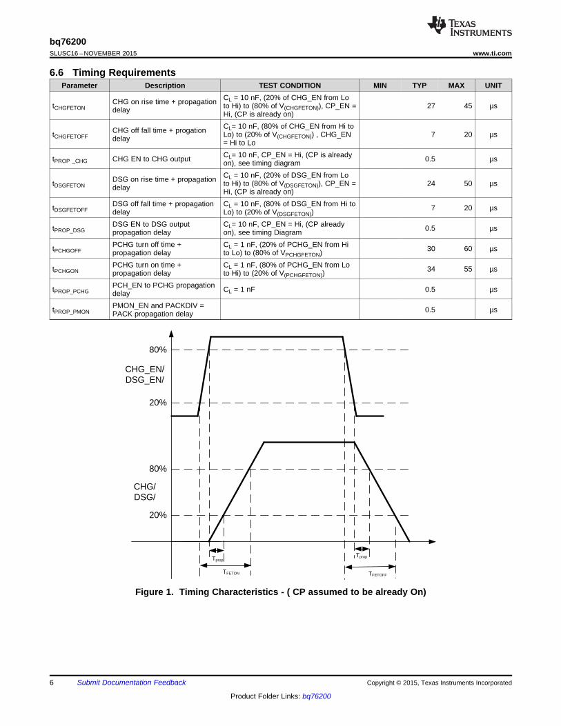
6.6 Timing RequirementsParameter Description TEST CONDITION MIN TYP MAX UNIT
CL = 10 nF, (20% of CHG_EN from LoCHG on rise time + propagationtCHGFETON to Hi) to (80% of V(CHGFETON)), CP_EN = 27 45 µsdelay Hi, (CP is already on)CL= 10 nF, (80% of CHG_EN from Hi toCHG off fall time + progationtCHGFETOFF Lo) to (20% of V(CHGFETON)) , CHG_EN 7 20 µsdelay = Hi to LoCL= 10 nF, CP_EN = Hi, (CP is alreadytPROP _CHG CHG EN to CHG output 0.5 µson), see timing diagramCL = 10 nF, (20% of DSG_EN from LoDSG on rise time + propagationtDSGFETON to Hi) to (80% of V(DSGFETON)), CP_EN = 24 50 µsdelay Hi, (CP is already on)
DSG off fall time + propagation CL = 10 nF, (80% of DSG_EN from Hi totDSGFETOFF 7 20 µsdelay Lo) to (20% of V(DSGFETON))DSG EN to DSG output CL= 10 nF, CP_EN = Hi, (CP alreadytPROP_DSG 0.5 µspropagation delay on), see timing DiagramPCHG turn off time + CL = 1 nF, (20% of PCHG_EN from HitPCHGOFF 30 60 µspropagation delay to Lo) to (80% of VPCHGFETON)PCHG turn on time + CL = 1 nF, (80% of PCHG_EN from LotPCHGON 34 55 µspropagation delay to Hi) to (20% of V(PCHGFETON))PCH_EN to PCHG propagationtPROP_PCHG CL = 1 nF 0.5 µsdelayPMON_EN and PACKDIV =tPROP_PMON 0.5 µsPACK propagation delay
Figure 1. Timing Characteristics - ( CP assumed to be already On)
6 Submit Documentation Feedback Copyright © 2015, Texas Instruments Incorporated
Product Folder Links: bq76200

Temperature (qC)
VP
CG
On
(V)
-50 -25 0 25 50 75 1006
8
10
12
14
16
D005
MinAverageMax
Input Voltage (V)
Inte
rnal
Rpd
(M:
)
0 2 4 6 8 10 12 14 160.5
0.75
1
1.25
1.5
1.75
D003
40qC25qC105qC
Temperature (qC)
FE
T O
n V
olta
ge (
V)
-50 -25 0 25 50 75 1009.5
9.75
10
10.25
10.5
10.75
11
11.25
11.5
D004D001
MinAverageMax
Temperature (qC)
Nor
mal
Mod
e C
urre
nt (P
A)
-50 -25 0 25 50 75 100 12522
24
26
28
30
32
34
36
D001
MinAverageMax
Temperature (qC)
Shu
tdow
n C
urre
nt (P
A
-50 -25 0 25 50 75 1004.5
5
5.5
6
6.5
7
D002
MinAverageMax
bq76200www.ti.com SLUSC16 –NOVEMBER 2015
6.7 Typical Characteristics
Figure 2. Normal Mode Current Vs Battery Figure 3. Shutdown Mode Current vs Battery
Figure 4. Input Pin Voltage for Internal Pull-Down Figure 5. CHG/DSG FET On Voltage vs TemperatureResistance (Rpd)
Figure 6. PCHG On Voltage vs Temperature
Copyright © 2015, Texas Instruments Incorporated Submit Documentation Feedback 7
Product Folder Links: bq76200

bq76200SLUSC16 –NOVEMBER 2015 www.ti.com
7 Detailed Description
7.1 OverviewThe bq76200 device is a low-power, high-side, N-Channel MOSFET driver for battery-pack protection systems,allowing a low-side battery-protection system to be implemented into a high-side protection system.
High-side charge/discharge FETs offer a huge advantage versus their low-side counterparts; with high-sideimplementation, a system-side processor can always communicate with the monitor or micro-controller (MCU)within the battery pack, regardless of whether the FETs are on or off — this is not easily supported in a low-sideswitching architecture due to the lack of a shared ground reference. One key benefit of an ever-presentcommunication link is the ability to read out critical pack parameters despite safety faults, thereby enabling thesystem to assess pack conditions before determining if normal operation may resume.
The device allows independent control on charging and discharge via the digital enable pins. The device hasintegrated charge pump which is enabled by the CP_EN pin. The enable inputs, CHG_EN, DSG_EN, andPCHG_EN control the CHG, DSG, and PCHG FET gate drivers, respectively. The enable inputs can beconnected to low-side FET driver outputs of an Analog Front End (AFE) such as Texas Instruments bq769x0series, a general purpose microcontroller, or dedicated battery pack controller such as the bq783xx series.
In normal mode, the AFE or MCU enables the CHG_EN and DSG_EN, turning on the CHG and DSG FETdrivers to connect the battery power to the PACK+ terminal. When a fault is detected by the AFE or themicrocontroller, it can disable the CHG_EN and/or DSG_EN to open the charge or discharge path for protection.Note that when either the CHG_EN or DSG_EN is enabled, the charge pump will be automatically enabled evenif the CP_EN is in the disable state. It is recommended to enable the charge pump via CP_EN pin during systemstart-up to avoid adding the tCPON time into the FET switching time during normal operation.
A lower charging current is usually applied to a deeply depleted battery pack. The bq76200 PCHG_EN inputprovides an option to implement a P-Channel MOSFET pre-charge path (current-limited path) in the battery pack.
An AFE usually provides individual cell voltages and/or battery stack voltage measurements, but it is notnecessary to have PACK+ voltage measurement. The bq76200 PMON_EN pin, when enabled, will connect thePACK+ voltage onto the PACKDIV pin, which is connected to an external resistor divider to scale down thePACK+ voltage. This scaled down PACK+ voltage can be connected to a microcontroller's ADC input for voltagemeasurement. The system can use this information for charger detection or to implement advanced chargingcontrol.
For safety purposes, all the enable inputs are internally pulled down. If the AFE or microcontroller is turned off, orif the PCB trace is damaged, the internal pull down of the enable inputs will keep CHG, DSG, PCHG in an offstate and the PACK+ voltage does not switch onto the PACKDIV pin.
8 Submit Documentation Feedback Copyright © 2015, Texas Instruments Incorporated
Product Folder Links: bq76200

ChargePump
PCHG_EN
CHG_EN
CP_EN
DSG_EN
Vcommon
PCHG
CHG
VDDCP
DSG
VSS
BAT PACK
Reference
Vcommon
UVLO
PMON_EN
PACKDIV
I/O
bq76200www.ti.com SLUSC16 –NOVEMBER 2015
7.2 Functional Block Diagram
Figure 7. Functional Block Diagram
7.3 Feature Description
7.3.1 Charge Pump ControlThe bq76200 device has an integrated charge pump. A minimum of 470-nF capacitor is required on the V(VDDCP)pin to the BAT pin to ensure proper function of the charge pump. If the V(VDDCP) capacitor is disconnected, aresidual voltage could reside at the CHG and/or DSG output if CHG_EN and/or DSG_EN are enabled. Such afault condition can put the external FETs in high Rdson state and result in FET damage.
Copyright © 2015, Texas Instruments Incorporated Submit Documentation Feedback 9
Product Folder Links: bq76200

bq76200SLUSC16 –NOVEMBER 2015 www.ti.com
Feature Description (continued)The V(VDDCP) capacitor can be scaled up to support more FETs in parallel (such as high-total FET-gatecapacitance) than the value specified in the electrical characteristics table. A higher VDDCP capacitance resultsin longer tCPON time. See the Application Information section for more information. Note that probing the VDDCPpin may increase the loading on the charge pump and result in lower measurement value than the V(VDDCP)specification. Using higher impedance probe can reduce such effect on the measurement.
The charge pump is controlled by CP_EN and also OR'ed with the CHG_EN and DSG_EN inputs. This meansby enabling CHG_EN or DSG_EN alone, the charge pump will automatically turn on even if the CP_EN pin isdisabled. The PCHG_EN controls the PCHG pin, which is a P-channel FET driver and does not require thefunction of the charge pump. The charge pump is turned off by default. When CP_EN is high, the charge pumpturns on regardless of the status of the CHG_EN and DSG_EN inputs.
When CP_EN is enabled, the charge pump voltage starts to ramp up. Once the voltage is above an internalUVLO level, about 9-V typical above VBAT, the charge pump is considered on. The charge pump voltage shouldcontinuously ramp to the V(VDDCP) level. If the CHG_EN and/or DSG_EN is enabled, the CHG and/or DSGvoltage will starts to turn on after the charge pump voltage is above the UVLO level, and ramp up along thecharge pump voltage to the V(VDDCP) level. Otherwise, the CHG and DSG do not turn on if the charge pumpvoltage fails to ramp up above UVLO. For example, if the C(VDDCP) is not scaled properly to support the numberof FETs in parallel, the heavy loading would prevent the charge pump to ramp up above UVLO. CHG and DSGwould not be turned on in this case.
When CHG_EN and/or DSG_EN is enabled after the charge pump is fully turned on, the CHG_EN-enable toCHG-on delay (or DSG_EN-enable to DSG-on delay) is simply the sum of (tprop + FET rise time). A systemconfiguration example for this scenario will be connecting the CP_EN to the host MCU, enable CP_EN at systemstart-up and keep the CP_EN enabled during normal operation. This is the recommended configuration, becausethe charge pump ramp-up time, tCPON, becomes part of the system start-up time and does not add onto the FETswitch delay during normal operation.
If CP_EN is not used (it is highly recommended to connect the CP_EN to ground), the charge pump on- and off-state is controlled by CHG_EN or DSG_EN. The CHG or DSG output will only be on after the charge-pumpvoltage is ramped up above UVLO. This means the CHG_EN-enable to CHG-on delay (or DSG_EN-enable toDSG-on delay) will be (tCPON + tprop + FET rise time).
The charge pump is turned off when CP_EN AND CHG_EN AND DSG_EN signals are all low. The charge pumpis not actively driven low and the voltage on the V(VDDCP) capacitor bleeds off passively. If any of the CP_EN,CHG_EN, or DSG_EN signals is switched high again while the V(VDDCP) capacitor is still bleeding off its charge,the charge pump start up time, tCPON, will be shorter.
7.3.2 Pin Enable ControlsThe bq76200 has four digital enable inputs that control the state of associated output signals as defined in thefollowing table. The VIH and VIL levels of these enable pins are low enough to work with most MCUs. At thesame times, the pins have high enough tolerant to allow direct control from an AFE FET driver. This givessystem maker a flexible option to architect the battery pack configuration.
INPUT PIN ASSOCIATED OUTPUT PIN DESCRIPTIONCHG_EN CHG Charge FET controlDSG_EN DSG Discharge FET control
PCHG_EN PCHG Pre-charge FET controlPMON_EN PACKDIV Pack monitor control
10 Submit Documentation Feedback Copyright © 2015, Texas Instruments Incorporated
Product Folder Links: bq76200

bq76200www.ti.com SLUSC16 –NOVEMBER 2015
7.3.2.1 External Control of CHG and DSG Output DriversThe CHG_EN and DSG_EN pins provide direct control of the CHG and DSG FET driver. Table 1 summarizesthe CHG and DSG statute with respect to the CP_EN, CHG_EN and DSG_EN inputs.
Table 1. CHG and DSG with Respect to CP_EN, CHG_EN, and DSG_ENCP_EN CHG_EN DSG_EN CHARGE PUMP CHG DSG
Lo (default) Lo (default) Lo (default) OFF (default) OFF (default) OFF (default)Lo Lo Hi ON OFF ONLo Hi Lo ON ON OFFLo Hi Hi ON ON ONHi Lo Lo ON OFF OFFHi Lo Hi ON OFF ONHi Hi Lo ON ON OFFHi Hi Hi ON ON ON
7.3.2.2 External Control of PCHG Output DriverThe PCHG output driver is designed to drive a P-channel FET and is controlled by the PCHG_EN pin. ThePCHG driver provides an option to implement a separate charging path with a P-channel FET to charge thebattery when the cells are deeply depleted. A resistor should be added in series to the P-channel pre-chargeFET to limit the charging current. A pre-charge current is usually at or less than 1/20 of the normal chargecurrent if the charger does not support lower current pre-charge. Refer to the battery cell specification from thecell manufacturer charging for the appropriate current limit.
PCHG_EN PCHGLo (default) OFF (default)
Hi ON
7.3.2.3 Pack Monitor EnableThe bq76200 device provides an internal-switch control to post the PACK+ voltage on to the PACKDIV pin. Aresistor divider can be connected to the PACKDIV pin externally to divide down the PACK+ voltage into ameasurable range of an MCU. The PMON_EN controls the internal switch between PACK pin and PACKDIV pin.The internal switch has an on resistance of R(PMONFET). The external resistor divider for PACKDIV pin should beselected to avoid exceeding the absolute maximum of the PACKDIV pin and should also keep the loading current< 500 µA. If this function is not used, the PACKDIV pin should leave floating. To reduce power consumption, thePMON_EN should be enabled only when PACK+ voltage measurement is needed.
PMON_EN PACKDIVLo (default) DISABLED (default)
Hi ENABLED
7.4 Device Functional Modes• In NORMAL mode, the bq76200 charge pump is turned on by enabling either CP_EN, CHG_EN, or DSG_EN.
In this mode, typically the CHG and DSG outputs are driven to V(BAT) + V(VDDCP).• In SHUTDOWN mode, the bq76200 is completely powered down. When CHG_EN, DSG_EN, and CP_EN are
driven low, the device enters SHUTDOWN mode, and the outputs are driven low.
DEVICE MODES CONDITIONNORMAL CHG_EN = Hi, DSG_EN = Hi, CP_EN = Hi, PCHG_EN = don't care, PMON_EN = don't careSHUTDOWN CHG_EN = Lo, DSG_EN = Lo, CP_EN = Lo, PCHG_EN = Lo, PMON_EN = Lo
Copyright © 2015, Texas Instruments Incorporated Submit Documentation Feedback 11
Product Folder Links: bq76200

bq76200SLUSC16 –NOVEMBER 2015 www.ti.com
8 Application and Implementation
NOTEInformation in the following applications sections is not part of the TI componentspecification, and TI does not warrant its accuracy or completeness. TI’s customers areresponsible for determining suitability of components for their purposes. Customers shouldvalidate and test their design implementation to confirm system functionality.
8.1 Application InformationThe bq76200 device is a high-side NMOS FET driver with integrated charge pump. The device can convert alow-side battery protection system into a high-side protection system, allowing the battery monitor device orbattery MCU to always maintain communication to the host system regardless if the protection FETs are on oroff. The device provides independent enables to control charge and discharge of a battery pack.
The following section highlights several recommended implementations when using this device. A detail bq76200Application Note, SLVA729, is available at www.ti.com.
8.1.1 Recommended System Implementation
8.1.1.1 The bq76200 is a Slave DeviceThe bq76200 is a FET driver. It controls the output pins (CHG, DSG, PCHG, and PACKDIV) according to theinput pin (CHG_EN, DSG_EN, PCHG_EN, CP_EN, and PMON_EN) status. The device does not validate if theinputs should or should not be turned on or off. For example, if both CHG_EN and PCHG_EN are enabled,bq76200 will turn on both CHG and PCHG simultaneously, enabling two charging paths to the system. Thesystem designer should avoid undesirable enable combination via schematic, AFE, or host MCU implementation.
8.1.1.2 Flexible Control via AFE or via MCUThe bq76200 device has simple-logic input pins (CHG_EN, DSG_EN, PCHG_EN, CP_EN, and PMON_EN) thatcan accept a control signal from any MCU I/O. At the same time, the input pins are designed to tolerate highvoltage signal such as the FET driver output from an AFE. This flexibility allows a mix of control input drivingfrom AFE and/or MCU to optimize the system design.
For example, it is recommended to control the CP_EN pin via MCU which the system can turn on the chargepump at system start-up, excluding the extra FET delay due to charge pump voltage ramping. On the other hand,the CHG_EN and DSG_EN can be driven by the AFE FET driver output, especially if the AFE has hardwareprotection features (such as the bq76920/30/40 family), to optimize the FET reaction time.
All the input pins have internal pull-down resistor. The outputs are default to be off if any of the input pins are athigh-Z state.
8.1.1.3 Scalable VDDCP Capacitor to Support Multiple FETs in ParallelThe bq76200 requires a minimum 470-nF capacitor to be connected between the VDDCP pin and BAT pin inorder to turn on the integrated charge pump. The Electrical Characteristics Specification of this documentspecified the device performance based on 10 nF loading with 470-nF VDDCP capacitor. The loadingcapacitance varies with FET choices, number of FETs in use, and in parallel and simultaneous switching versussequential switching of CHG and DSG FET.
The more FETs that are in parallel, the higher the loading capacitance. Similarly, simultaneously switching of theCHG and DSG FET loads down the charge pump more than sequentially switching both FETs. Eventually, theloading capacitance can exceed the supported range of a 470-nF VDDCP capacitor. A > 470-nF VDDCPcapacitor can be used to support higher-loading capacitance.
12 Submit Documentation Feedback Copyright © 2015, Texas Instruments Incorporated
Product Folder Links: bq76200

CVDDCP
bq76200CHG
NC
CP_EN
CHG_EN
BAT
VDDCP
PMON_EN
DSG_EN
PCHG_EN
NC
PACKDIV
PCHG
NC
DSG
PACK
VSS
PACK-
PACK+
100
0.01 µF
bq76200www.ti.com SLUSC16 –NOVEMBER 2015
Application Information (continued)
Figure 8. Scale CVDDCP to Support Multiple FETs in Parallel (Partial Schematic Shown)
Based on test results, 470-nF VDDCP capacitor can support up to approximately 30-nF loading capacitance.Using a 470-nF/20-nF ratio (to include some design margin), a 2.1-µF VCCDP capacitor can support up to ~90nF loading capacitance. Note that a larger VDDCP capacitor increases the charge pump start up time; a higherloading capacitance increases the FET on and off time. System designers should test across the operation rangeto ensure the design margin and system performance. Refer to the bq76200 Application note for more testresults.
Also notice that any damage or disconnection of the VDDCP capacitor during operation can leave a residualvoltage on the FET driver output if the inputs are enabled. This can result in putting the external FETs in a high-Rdson state and cause FET damage.
8.1.1.4 Pre-Charge and Pre-Discharge SupportFor a deeply depleted battery pack, a much lower charging current, for example, a C/10 rate, is usually used topre-charge the battery cells. This allows the passivating layer of the cell to be recovered slowly (the passivatinglayer might be dissolved in the deep discharge state).
The bq76200 has a PCHG output to drive an external P-channel FET to support battery pre-charge. In thisscenario, the external P-channel FET is placed in parallel with the CHG FET and a power resistor can beconnected in series of the P-channel FET to limit the charging current during the pre-charge state. The MCU canbe used to control the PCHG_EN pin to determine the entry and exit of the pre-charge mode.
Copyright © 2015, Texas Instruments Incorporated Submit Documentation Feedback 13
Product Folder Links: bq76200

470 nF
bq76200CHG
NC
CP_EN
CHG_EN
BAT
VDDCP
PMON_EN
DSG_EN
PCHG_EN
NC
PACKDIV
PCHG
NC
DSG
PACK
VSS
Rpchg
PACK-
PACK+
100
0.01 µF
From MCU
bq76200SLUSC16 –NOVEMBER 2015 www.ti.com
Application Information (continued)
Figure 9. P-channel FET in Parallel With CHG FET for Pre-Charging (Partial Schematic Shown)
Alternatively, the CHG pin can also be used to pre-charge a battery pack given if the charging current iscontrolled by the system (i.e. does not require external component to limit the charging current such as a smartcharger) and the battery stack voltage is higher than minimum operation voltage of the bq76200 (i.e. the chargepump can start to turn on the CHG FET). PCHG should leave floating if it is not used in the application.
The PCHG output can be used to pre-discharge a high-capacitive system. For example, a load removal can beone of the recovery requirements after a discharge related fault has been detected. In a high-capacitive system,the residual voltage at the system side can take a significant time to bleed off. This results in an additional delayin fault recovery. The PCHG output can be used to control an external P-channel FET placed in parallel with theDSG FET to pre-discharge the residual voltage in order to speed up the fault recovery process.
14 Submit Documentation Feedback Copyright © 2015, Texas Instruments Incorporated
Product Folder Links: bq76200

470 nF
bq76200CHG
NC
CP_EN
CHG_EN
BAT
VDDCP
PMON_EN
DSG_EN
PCHG_EN
NC
PACKDIV
PCHG
NC
DSG
PACK
VSS
Rpdsg
10 M 10 M
PACK-
PACK+
100
0.01 µF
From MCU
bq76200www.ti.com SLUSC16 –NOVEMBER 2015
Application Information (continued)
Figure 10. P-channel FET in Parallel with DSG FET for Pre-Discharging (Partial Schematic Shown)
8.1.1.5 Optional External Gate ResistorThe CHG and DSG have certain internal on and off resistance. However, an optional external gate resistor canbe added to CHG and/or DSG FET to slow down the FET on and off timing.
8.1.1.6 Separate Charge and Discharge pathsIn some systems, the charging current might be significantly lower than the discharge current. In such systems,the system designer may prefer to implement a separate charge and discharge paths in which the number ofFET in parallel for charge and discharge can be different to reduce to BOM cost.
Copyright © 2015, Texas Instruments Incorporated Submit Documentation Feedback 15
Product Folder Links: bq76200

470 nF
bq76200CHG
NC
CP_EN
CHG_EN
BAT
VDDCP
PMON_EN
DSG_EN
PCHG_EN
NC
PACKDIV
PCHG
NC
DSG
PACK
VSS
PACK-
Discharge
100
0.01 µF
Charge
bq76200SLUSC16 –NOVEMBER 2015 www.ti.com
Application Information (continued)
Figure 11. Separate Charge and Discharge Paths (Partial Schematic Shown)
16 Submit Documentation Feedback Copyright © 2015, Texas Instruments Incorporated
Product Folder Links: bq76200

Rc
Rc
Rc
Rc
Rsns
Cc
Cc
Cc
Cc
Cc
100
0.1 µF
4.7 µF
VC5x
VC5
VC4
VC3
VC2
VC1
VSS
SCL
SDA
CHG
DSG
REGSRC
REGOUT
SRN
SRP
VC0
CAP1
TS1 Cf
100
0.1 µF
1 µF
Rc
Rc
10 k
ALERT
PUSH-BUTTON FOR BOOT
VCC
GPIO
SDA
SCL
VSS
µC
Cc
1 µF
0.1 µF
10 N
PACK+
PACK-
VC10
VC9
VC8
VC7
VC6
VC5b
Rc
Rc
Rc
Rc
Cc
Cc
Cc
Cc
Cc
Rc
Rc
Cc
VC10x
CAP2
TS2 Cf
Rf
1 µF10kRf
A
A
VC15
VC14
VC13
VC12
VC11
VC10b
Rc
Rc
Rc
Rc
Cc
Cc
Cc
Cc
Cc
Rc
Rc
Cc
B
BAT
CAP3
TS3
bq76940
Cf1 µF10k Rf
B
GPIO
470 nFCVDDCP
GPIO
Rb
Ra
10 M Rgs
1 M Rpchg
10 M Rgs
10 M Rgs
ADC_IN
bq76200CHG
NC
CP_EN
CHG_EN
BAT
VDDCP
PMON_EN
DSG_EN
PCHG_EN
NC
PACKDIV
PCHG
NC
DSG
PACK
VSS
GPIO
VC10x
VC5x
100 Rfilter
0.01 µFCfilter
100 Rfilter
0.01 µFCfilter
Analog Front End
bq76200www.ti.com SLUSC16 –NOVEMBER 2015
8.2 Typical Applications
8.2.1 Design RequirementsFor this design example, use the parameters listed in Table 2.
Table 2. Design ParametersPARAMETER EXTERNAL COMPONENT NOTE
BAT and PACK Filters Rfilter and Cfilter Recommended to use 100 Ω and 0.01 µF.A minimum of 470 µF is required. A higher value can be used to
VDDCP capacitor CVDDCP support higher-loading capacitance. See RecommendedImplementation and bq76200 Application Note () for details.Based on the max PACK voltage of the application, calculate the
PACKDIV resistor divider Ra and Rb total value of (Ra + Rb) that can keep the PACKDIV current below500 µA.Recommended to use 10 MΩ. A different Rgs value may change theCHG, DSG, PCHG gate-source Rgs loading level of the charge pump. System designer should performresistor thorough system testing if a different Rgs is used.
Copyright © 2015, Texas Instruments Incorporated Submit Documentation Feedback 17
Product Folder Links: bq76200

bq76200SLUSC16 –NOVEMBER 2015 www.ti.com
8.2.2 Detailed Design Procedure1. Determine if CP_EN pin will be driven by MCU. It is highly recommended to use CP_EN to turn on the
charge pump at system start-up. However, it is not a must to operate the bq76200 to switch on CHG andDSG pins. System designer should ensure the FET's turn on time is acceptable during normal operation ifCP_EN is not enabled at system startup.
2. Select the correct VDDCP capacitance. Scaling up the VDDCP capacitance allows support for a highernumber of FETs in parallel. This test result of various parallel FETs versus VDDCP capacitance in thebq76200 application is for general reference only. System designer should always validate their designtolerant across operation temperature range.
3. If the PMON_EN is used, the PACKDIV resistor divider, Ra and Rb, must be selected to satisfy (Ra+Rb) <500uA, AND [Rb/(Ra + Rb)] < (max ADC input range)/(max PACK+ voltage). For example, In a 48V system,if the max charger voltage is 50.4V and a MCU's max ADC input is 3V. To meet both (Ra + Rb) < 500uA,AND [Rb/(Ra + Rb)] < (3V/50.4V) requirements, the Ra value might be 100 kΩ or less and Rb value might be6 KΩ or less.
4. Follow the application schematic (see Typical Applications) to connect the device.
8.2.3 Application Curves
CHG output reacts to the CHG_EN signal immediately. Similar CHG output reacts to the CHG_EN signal after charge pumpbehavior applies to DSG pin. startup delay. Similar behavior applies to DSG pin.
Figure 12. CHG_EN Switched On After Charger Pump Figure 13. CHG_EN Enabled Before Charge Pump isTurns On and is Stable Turned On
With 10 nF loading and no Rgs on DSG output. Note the time scale was 800ns/div. Hence, the DSG waveform above wasbasically the DSG FET fall time
Figure 14. DSG_EN to DSG Output Propagation Delay
18 Submit Documentation Feedback Copyright © 2015, Texas Instruments Incorporated
Product Folder Links: bq76200

CVDDCP
bq76200CHG
NC
CP_EN
CHG_EN
BAT
VDDCP
PMON_EN
DSG_EN
PCHG_EN
NC
PACKDIV
PCHG
NC
DSG
PACK
VSS
PACK-
PACK+
100
0.01 µF
100
0.01 µF
Place these components close to the device pins
bq76200www.ti.com SLUSC16 –NOVEMBER 2015
9 Power Supply RecommendationsThe maximum recommended operation voltage on the BAT and PACK pins is 75 V. The charge pump, when itturns on, will add 14 V maximum voltage on top of the BAT or PACK voltage to the device, pushing the totaldevice voltage to approximately 89 V.
The bq76200 has high voltage (100 V) tolerant pins, but system designer should take into account the worse-case transient voltage and the maximum charge pump on voltage to determine the maximum voltage applying toBAT and PACK pins.
10 Layout
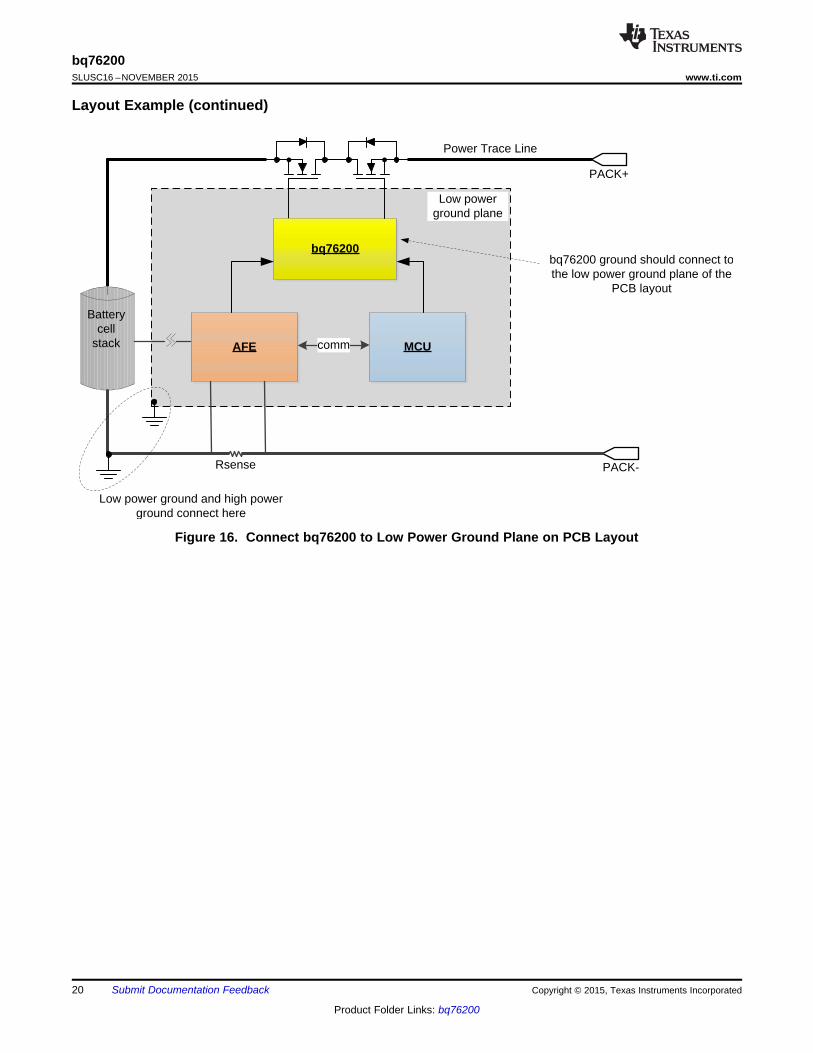
10.1 Layout GuidelinesFor the following procedure, see Figure 15 and Figure 16.1. Place CVDDCP capacitor close to the device.2. Place BAT and PACK RC filters close to the device.3. Generally, a typical system using an AFE, MCU, and bq76200 usually have a high-current ground
trace/plane and low-current ground plane in the PCB layout. If so, the bq76200 ground should be connectedto the low-current ground plane of the PCB layout to remove noise affecting the ENABLE signals.
10.2 Layout Example
Figure 15. Place CVDDCP and Filter Components Close to Device
Copyright © 2015, Texas Instruments Incorporated Submit Documentation Feedback 19
Product Folder Links: bq76200
PACK-
PACK+
Battery cell
stack AFE
Rsense
bq76200
MCUcomm
Power Trace Line
Low power ground plane
Low power ground and high power ground connect here
bq76200 ground should connect to the low power ground plane of the
PCB layout
bq76200SLUSC16 –NOVEMBER 2015 www.ti.com
Layout Example (continued)
Figure 16. Connect bq76200 to Low Power Ground Plane on PCB Layout
20 Submit Documentation Feedback Copyright © 2015, Texas Instruments Incorporated
Product Folder Links: bq76200

bq76200www.ti.com SLUSC16 –NOVEMBER 2015
11 Device and Documentation Support
11.1 Documentation Support
11.1.1 Related DocumentationFor related documentation, see the bq76200 FET Configurations Test Results (SLVA729).
11.2 Community ResourcesThe following links connect to TI community resources. Linked contents are provided "AS IS" by the respectivecontributors. They do not constitute TI specifications and do not necessarily reflect TI's views; see TI's Terms ofUse.
TI E2E™ Online Community TI's Engineer-to-Engineer (E2E) Community. Created to foster collaborationamong engineers. At e2e.ti.com, you can ask questions, share knowledge, explore ideas and helpsolve problems with fellow engineers.
Design Support TI's Design Support Quickly find helpful E2E forums along with design support tools andcontact information for technical support.
11.3 TrademarksE2E is a trademark of Texas Instruments.
11.4 Electrostatic Discharge CautionThis integrated circuit can be damaged by ESD. Texas Instruments recommends that all integrated circuits be handled withappropriate precautions. Failure to observe proper handling and installation procedures can cause damage.
ESD damage can range from subtle performance degradation to complete device failure. Precision integrated circuits may be moresusceptible to damage because very small parametric changes could cause the device not to meet its published specifications.
11.5 GlossarySLYZ022 — TI Glossary.
This glossary lists and explains terms, acronyms, and definitions.
12 Mechanical, Packaging, and Orderable InformationThe following pages include mechanical packaging and orderable information. This information is the mostcurrent data available for the designated devices. This data is subject to change without notice and revision ofthis document. For browser-based versions of this data sheet, refer to the left-hand navigation.
Copyright © 2015, Texas Instruments Incorporated Submit Documentation Feedback 21
Product Folder Links: bq76200

PACKAGE OPTION ADDENDUM
www.ti.com 3-Dec-2015
Addendum-Page 1
PACKAGING INFORMATION
Orderable Device Status(1)
Package Type PackageDrawing
Pins PackageQty
Eco Plan(2)
Lead/Ball Finish(6)
MSL Peak Temp(3)
Op Temp (°C) Device Marking(4/5)
Samples
BQ76200PW ACTIVE TSSOP PW 16 90 Green (RoHS& no Sb/Br)
CU NIPDAU Level-2-260C-1 YEAR -40 to 85 BQ7620B
BQ76200PWR ACTIVE TSSOP PW 16 2000 Green (RoHS& no Sb/Br)
CU NIPDAU Level-2-260C-1 YEAR -40 to 85 BQ7620B
(1) The marketing status values are defined as follows:ACTIVE: Product device recommended for new designs.LIFEBUY: TI has announced that the device will be discontinued, and a lifetime-buy period is in effect.NRND: Not recommended for new designs. Device is in production to support existing customers, but TI does not recommend using this part in a new design.PREVIEW: Device has been announced but is not in production. Samples may or may not be available.OBSOLETE: TI has discontinued the production of the device.
(2) Eco Plan - The planned eco-friendly classification: Pb-Free (RoHS), Pb-Free (RoHS Exempt), or Green (RoHS & no Sb/Br) - please check http://www.ti.com/productcontent for the latest availabilityinformation and additional product content details.TBD: The Pb-Free/Green conversion plan has not been defined.Pb-Free (RoHS): TI's terms "Lead-Free" or "Pb-Free" mean semiconductor products that are compatible with the current RoHS requirements for all 6 substances, including the requirement thatlead not exceed 0.1% by weight in homogeneous materials. Where designed to be soldered at high temperatures, TI Pb-Free products are suitable for use in specified lead-free processes.Pb-Free (RoHS Exempt): This component has a RoHS exemption for either 1) lead-based flip-chip solder bumps used between the die and package, or 2) lead-based die adhesive used betweenthe die and leadframe. The component is otherwise considered Pb-Free (RoHS compatible) as defined above.Green (RoHS & no Sb/Br): TI defines "Green" to mean Pb-Free (RoHS compatible), and free of Bromine (Br) and Antimony (Sb) based flame retardants (Br or Sb do not exceed 0.1% by weightin homogeneous material)
(3) MSL, Peak Temp. - The Moisture Sensitivity Level rating according to the JEDEC industry standard classifications, and peak solder temperature.
(4) There may be additional marking, which relates to the logo, the lot trace code information, or the environmental category on the device.
(5) Multiple Device Markings will be inside parentheses. Only one Device Marking contained in parentheses and separated by a "~" will appear on a device. If a line is indented then it is a continuationof the previous line and the two combined represent the entire Device Marking for that device.
(6) Lead/Ball Finish - Orderable Devices may have multiple material finish options. Finish options are separated by a vertical ruled line. Lead/Ball Finish values may wrap to two lines if the finishvalue exceeds the maximum column width.
Important Information and Disclaimer:The information provided on this page represents TI's knowledge and belief as of the date that it is provided. TI bases its knowledge and belief on informationprovided by third parties, and makes no representation or warranty as to the accuracy of such information. Efforts are underway to better integrate information from third parties. TI has taken andcontinues to take reasonable steps to provide representative and accurate information but may not have conducted destructive testing or chemical analysis on incoming materials and chemicals.TI and TI suppliers consider certain information to be proprietary, and thus CAS numbers and other limited information may not be available for release.

PACKAGE OPTION ADDENDUM
www.ti.com 3-Dec-2015
Addendum-Page 2
In no event shall TI's liability arising out of such information exceed the total purchase price of the TI part(s) at issue in this document sold by TI to Customer on an annual basis.

TAPE AND REEL INFORMATION
*All dimensions are nominal
Device PackageType
PackageDrawing
Pins SPQ ReelDiameter
(mm)
ReelWidth
W1 (mm)
A0(mm)
B0(mm)
K0(mm)
P1(mm)
W(mm)
Pin1Quadrant
BQ76200PWR TSSOP PW 16 2000 330.0 12.4 6.9 5.6 1.6 8.0 12.0 Q1
PACKAGE MATERIALS INFORMATION
www.ti.com 13-Feb-2016
Pack Materials-Page 1

*All dimensions are nominal
Device Package Type Package Drawing Pins SPQ Length (mm) Width (mm) Height (mm)
BQ76200PWR TSSOP PW 16 2000 367.0 367.0 38.0
PACKAGE MATERIALS INFORMATION
www.ti.com 13-Feb-2016
Pack Materials-Page 2


IMPORTANT NOTICE
Texas Instruments Incorporated and its subsidiaries (TI) reserve the right to make corrections, enhancements, improvements and otherchanges to its semiconductor products and services per JESD46, latest issue, and to discontinue any product or service per JESD48, latestissue. Buyers should obtain the latest relevant information before placing orders and should verify that such information is current andcomplete. All semiconductor products (also referred to herein as “components”) are sold subject to TI’s terms and conditions of salesupplied at the time of order acknowledgment.TI warrants performance of its components to the specifications applicable at the time of sale, in accordance with the warranty in TI’s termsand conditions of sale of semiconductor products. Testing and other quality control techniques are used to the extent TI deems necessaryto support this warranty. Except where mandated by applicable law, testing of all parameters of each component is not necessarilyperformed.TI assumes no liability for applications assistance or the design of Buyers’ products. Buyers are responsible for their products andapplications using TI components. To minimize the risks associated with Buyers’ products and applications, Buyers should provideadequate design and operating safeguards.TI does not warrant or represent that any license, either express or implied, is granted under any patent right, copyright, mask work right, orother intellectual property right relating to any combination, machine, or process in which TI components or services are used. Informationpublished by TI regarding third-party products or services does not constitute a license to use such products or services or a warranty orendorsement thereof. Use of such information may require a license from a third party under the patents or other intellectual property of thethird party, or a license from TI under the patents or other intellectual property of TI.Reproduction of significant portions of TI information in TI data books or data sheets is permissible only if reproduction is without alterationand is accompanied by all associated warranties, conditions, limitations, and notices. TI is not responsible or liable for such altereddocumentation. Information of third parties may be subject to additional restrictions.Resale of TI components or services with statements different from or beyond the parameters stated by TI for that component or servicevoids all express and any implied warranties for the associated TI component or service and is an unfair and deceptive business practice.TI is not responsible or liable for any such statements.Buyer acknowledges and agrees that it is solely responsible for compliance with all legal, regulatory and safety-related requirementsconcerning its products, and any use of TI components in its applications, notwithstanding any applications-related information or supportthat may be provided by TI. Buyer represents and agrees that it has all the necessary expertise to create and implement safeguards whichanticipate dangerous consequences of failures, monitor failures and their consequences, lessen the likelihood of failures that might causeharm and take appropriate remedial actions. Buyer will fully indemnify TI and its representatives against any damages arising out of the useof any TI components in safety-critical applications.In some cases, TI components may be promoted specifically to facilitate safety-related applications. With such components, TI’s goal is tohelp enable customers to design and create their own end-product solutions that meet applicable functional safety standards andrequirements. Nonetheless, such components are subject to these terms.No TI components are authorized for use in FDA Class III (or similar life-critical medical equipment) unless authorized officers of the partieshave executed a special agreement specifically governing such use.Only those TI components which TI has specifically designated as military grade or “enhanced plastic” are designed and intended for use inmilitary/aerospace applications or environments. Buyer acknowledges and agrees that any military or aerospace use of TI componentswhich have not been so designated is solely at the Buyer's risk, and that Buyer is solely responsible for compliance with all legal andregulatory requirements in connection with such use.TI has specifically designated certain components as meeting ISO/TS16949 requirements, mainly for automotive use. In any case of use ofnon-designated products, TI will not be responsible for any failure to meet ISO/TS16949.
Products ApplicationsAudio www.ti.com/audio Automotive and Transportation www.ti.com/automotiveAmplifiers amplifier.ti.com Communications and Telecom www.ti.com/communicationsData Converters dataconverter.ti.com Computers and Peripherals www.ti.com/computersDLP® Products www.dlp.com Consumer Electronics www.ti.com/consumer-appsDSP dsp.ti.com Energy and Lighting www.ti.com/energyClocks and Timers www.ti.com/clocks Industrial www.ti.com/industrialInterface interface.ti.com Medical www.ti.com/medicalLogic logic.ti.com Security www.ti.com/securityPower Mgmt power.ti.com Space, Avionics and Defense www.ti.com/space-avionics-defenseMicrocontrollers microcontroller.ti.com Video and Imaging www.ti.com/videoRFID www.ti-rfid.comOMAP Applications Processors www.ti.com/omap TI E2E Community e2e.ti.comWireless Connectivity www.ti.com/wirelessconnectivity
Mailing Address: Texas Instruments, Post Office Box 655303, Dallas, Texas 75265Copyright © 2016, Texas Instruments Incorporated