brain–controlled wheelchairs: a robotic architecture
TRANSCRIPT

1
Brain–Controlled Wheelchairs:A Robotic Architecture
Tom Carlson, Member IEEE, and Jose del R. Millan, Senior Member IEEE
Abstract—Independent mobility is core to being able to per-form activities of daily living by oneself. However, poweredwheelchairs are not an option for a large number of peoplewho are unable to use conventional interfaces, due to severemotor–disabilities. For some of these poeple, non–invasive brain–computer interfaces (BCIs) offer a promising solution to thisinteraction problem and in this article we present a sharedcontrol architecture that couples the intelligence and desires ofthe user with the precision of a powered wheelchair. We show howfour healthy subjects are able to master control of the wheelchairusing an asynchronous motor–imagery based BCI protocol andhow this results in a higher overall task performance, comparedwith alternative synchronous P300–based approaches.
I. INTRODUCTION
Millions of people around the world suffer from mobilityimpairments and hundreds of thousands of them rely uponpowered wheelchairs to get on with their activities of dailyliving [1]. However, many patients are not prescribed pow-ered wheelchairs at all, either because they are physicallyunable to control the chair using a conventional interface,or because they are deemed incapable of driving safely [2].Consequently, it has been estimated that between 1.4 and 2.1million wheelchair users might benefit from a smart poweredwheelchair, if it were able to provide a degree of additionalassistance to the driver [3].
In our work with brain–actuated wheelchairs, we targeta population who are—or will become—unable to use con-ventional interfaces, due to severe motor–disabilities. Non-invasive brain–computer interfaces (BCIs) offer a promisingnew interaction modality, that does not rely upon a fully–functional peripheral nervous system to mechanically interactwith the world and instead uses the brain activity directly.However, mastering the use of a BCI, like with all newskills, does not come without a few challenges. Spontaneouslyperforming mental tasks to convey one’s intentions to a BCIcan require a high level of concentration, so it would result in afantastic mental workload, if one had to precisely control everymovement of the wheelchair. Furthermore, due to the noisynature of brain signals, we are currently unable to achieve thesame information rates that you might get from a joystick,which would make it difficult to wield such levels of controleven if one wanted to.
Thankfully, we are able to address these issues through theuse of intelligent robotics, as will be discussed. Our wheelchairuses the notion of shared control to couple the intelligence ofthe user with the precise capabilities of a robotic wheelchair,
T. Carlson and J. d. R. Millan are with the Defitech Chair in Non-InvasiveBrain Machine Interface (CNBI), Ecole Polytechnique Federale de Lausanne(EPFL), Station 11, 1015 Lausanne, Switzerland. [email protected]
given the context of the surroundings [4]. It is this synergy,which begins to make brain–actuated wheelchairs a potentiallyviable assistive technology of the not–so–distant future.
In this paper we describe the overall robotic architectureof our brain–actuated wheelchair. We begin by discussingthe brain computer interface, since the human is central toour design philosophy. Then, the wheelchair hardware andmodifications are described, before we explain how the sharedcontrol system fuses the multiple information sources in orderto decide how to execute appropriate manoeuvres in coopera-tion with the human operator. Finally, we present the resultsof an experiment involving four healthy subjects and comparethem with those reported on other brain–actuated wheelchairs.We find that our continuous control approach offers a verygood level of performance, with experienced BCI wheelchairoperators achieving a comparable performance to that of amanual benchmark condition.
II. BRAIN COMPUTER INTERFACES (BCI)
The electrical activity of the brain can be monitored in real–time using an array of electrodes, which are placed on thescalp in a process known as electroencephalography (EEG).In order to bypass the peripheral nervous system, we need tofind some reliable correlates in the brain signals that can bemapped to the intention to perform specific actions. In the nexttwo subsections, we first discuss the philosophy of differentBCI paradigms, before explaining our chosen asynchronousimplementation for controlling the wheelchair.
A. The BCI Philosophy
Many BCI implementations, rely upon the subject attendingto visual stimuli, which are presented on a screen. Conse-quently, researchers are able to detect a specific event–relatedpotential in the EEG, known as the P300, which is exhibited300 ms after a rare stimulus has been presented. For example,in one P300–based BCI wheelchair, the user is presented witha 3×3 grid of possible destinations from a known environment(e.g. the bathroom, the kitchen etc., within the user’s house),which are highlighted in a standard oddball paradigm [5]. Theuser then has to focus on looking at the particular option towhich they wish to drive. Once the BCI has detected theirintention, the wheelchair drives autonomously along a pre-defined route and the user is able to send a mental emergencystop command (if required) with an average of 6 seconds delay.
Conversely, another BCI wheelchair, which is also basedupon the P300 paradigm doesn’t restrict the user to navigatingin known, pre–mapped environments. Instead, in this design,the user is able to select subgoals (such as close left, far right,
© 2012 IEEE. Personal use of this material is permitted. Permission from IEEE must be obtained for all other uses, in any current or future media, including reprinting/republishing this material for advertising or promotional purposes, creating new collective works, for resale or redistribution to servers or lists, or reuse of any copyrighted component of this work in other works.
This article is the accepted preprint of the version that was published in the IEEE Robotics and Automation Magazine. 20(1): 65 – 73, March 2013. DOI: 10.1109/MRA.2012.2229936

2
mid–ahead etc.) from an augmented reality matrix superim-posed on a representation of the surrounding environment [6].To minimise errors (at the expense of command delivery time),after a subgoal has been pre–selected, the user then has tofocus on a validation option. This gives users more flexibilityin terms of following trajectories of their choice, however, thewheelchair has to stop each time it reaches the desired sub–goal and wait for the next command (and validation) from theuser. Consequently, when driving to specific destinations, thewheelchair was stationary for more time than it was actuallymoving (as can be seen in Fig. 8 of [6]).
Our philosophy is to keep as much authority with the usersas possible, whilst enabling them to dynamically generatenatural and efficient trajectories. Rather than using externalstimuli to evoke potentials in the brain, as is done in theP300 paradigm, we allow the user to spontaneously andasynchronously control the wheelchair by performing a motorimagery task. Since this does not rely on visual stimuli, it doesnot interfere with the visual task of navigation. Furthermore,when dealing with motor–disabled patients, it makes sense touse motor imagery, since this involves a part of the cortex,which may have effectively become redundant; i.e. the taskdoes not interfere with the residual capabilities of the patient.
Previously, we have demonstrated that it is possible to drivea wheelchair using such a protocol [7]. However, this earliersystem relied upon an expensive laser scanner to map theenvironment. In Section III, we show how a combination ofrelatively cheap sensors is sufficient to provide environmentalfeedback to the wheelchair controller. Moreover, the originalprotocol required the user to continuously deliver commands todrive the wheelchair, which resulted in a high user workload.Our current BCI protocol, coupled with shared control (seeSection IV) has reduced this workload.
In our motor imagery (MI) paradigm, the user is required toimagine the kinaesthetic movement of the left hand, the righthand or both feet, yielding three distinct classes. During theBCI training process, we select the two most discriminableclasses to provide a reliable mapping from the MI tasks tocontrol actions (e.g imagine left hand movements to deliver aturn left command and right hand movements to turn right).
To control our BCI wheelchair, at any moment, the usercan spontaneously issue a high–level turn left or turn rightcommand. When one of these two turning commands is notdelivered by the user, a third implicit class of intentionalnon–control exists, whereby the wheelchair continues to travelforward and automatically avoid obstacles where necessary.Consequently, this reduces the user’s cognitive workload. Theimplementation will be discussed in Section IV-D.
B. The BCI Implementation
Since we are interested in detecting motor imagery, weacquire monopolar EEG at a rate of 512 Hz from the mo-tor cortex using 16 electrodes (see Fig. 1). The electricalactivity of the brain is diffused as it passes through theskull, which results in a spatial blur of the signals, so weapply a Laplacian filter, which attenuates the common activitybetween neighbouring electrodes and consequently improves
Fig. 1: The active electrode placement over the motor cortexfor the acquisition of EEG data, based on the International10-20 system (nose at top).
our signal to noise ratio. After the filtering, we estimate thepower spectral density (PSD) over the last second, in theband 4–48 Hz with a 2 Hz resolution [8]. It is well knowthat when one performs motor imagery tasks, correspondingparts of the motor cortex are activated, which, as a result ofevent related desynchronisation, yields a reduction in the muband power (∼ 8–13 Hz) over these locations (e.g. the righthand corresponds to approximately C1 and the left hand toapproximately C2 in Fig. 1). In order to detect these changes,we estimate the PSD features every 62.5 ms (i.e. 16 timesper second) using the Welch method with 5 overlapped (25%)Hanning windows of 500 ms.
Every person is different, so we have to select the featuresthat best reflect the motor–imagery task for each subject.Therefore, canonical variate analysis (CVA) is used to selectsubject–specific features that maximize the separability be-tween the different tasks and that are most stable (accordingto cross validation on the training data) [9]. These featuresare then used to train a Gaussian classifier [10]. Decisionswith a confidence on the probability distribution that are belowa given rejection threshold are filtered out. Finally, evidenceabout the executed task is accumulated using an exponentialsmoothing probability integration framework [11]. This helpsto prevent commands from being delivered accidentally.
III. WHEELCHAIR HARDWARE
Our brain–controlled wheelchair is based upon a commer-cially available mid–wheel drive model by Invacare that wehave modified. First, we have developed a remote joystickmodule that acts as an interface between a laptop computer andthe wheelchair’s CANBUS–based control network. This allowsus to control the wheelchair directly from a laptop computer.Second, we have added a pair of wheel–encoders to thecentral driving wheels in order to provide the wheelchair withfeedback about its own motion. Third, an array of ten sonarsensors and two webcams have been added to the wheelchairto provide environmental feedback to the controller. Fourth,we have mounted an adjustable 8” display to provide visualfeedback to the user. Fifth, we have built a power distribution
© 2012 IEEE. Personal use of this material is permitted. Permission from IEEE must be obtained for all other uses, in any current or future media, including reprinting/republishing this material for advertising or promotional purposes, creating new collective works, for resale or redistribution to servers or lists, or reuse of any copyrighted component of this work in other works.
This article is the accepted preprint of the version that was published in the IEEE Robotics and Automation Magazine. 20(1): 65 – 73, March 2013. DOI: 10.1109/MRA.2012.2229936

3
Fig. 2: The complete brain–actuated wheelchair. The wheelchair’s knowledge of the environment is acquired by the fusionof complementary sensors and is represented as a probabilistic occupancy grid. The user is given feedback about the currentstatus of the BCI and about the wheelchair’s knowledge of the environment.
unit, to hook up all the sensors, the laptop and the displayto the wheelchair’s batteries. The complete BCI wheelchairplatform is shown in Fig. 2. The positions of the sonars areindicated by the white dots in the centre of the occupancygrid, whereas the two webcams are positioned forward–facing,directly above each of the front castor wheels.
A. Wheel–encodersThe encoders return 128 ticks per revolution and are geared
up to the rim of the drive wheels, resulting in a resolution of2.75×10−3 metres translation of the inflated drive wheel perencoder tick. We use this information to calculate the averagevelocities of the left and right wheels for each time–step. Notonly is this important feedback to regulate the wheelchaircontrol signals, but we also use it as the basis for deadreckoning (or estimating the trajectory that has been driven).We apply the simple differential drive model derived in [12].To ensure that the model is always analytically solvable,we neglect the acceleration component. In practice, since inthis application we are only using the odometry to update a6 m×6 m map, this does not prove to be a problem. However,if large degrees of acceleration or slippage occur and theodometry does not receive any external correcting factors, themodel will begin to accumulate significant errors [12].
IV. SHARED CONTROL ARCHITECTURE
The job of the shared controller is to determine the meaningof the vague, high–level user input (e.g. turn left, turn right,keep going straight), given the context of the surroundingenvironment [4]. We do not want to restrict ourselves to aknown, mapped environment—since it may change at anytime (e.g. due to human activities)—so the wheelchair mustbe capable of perceiving its surroundings. Then, the sharedcontroller can determine what actions should be taken, basedupon the user’s input, given the context of the surroundings.The overall robotic shared control architecture is depicted inFig. 3 and we discuss the perception and planning blocks ofthe controller over then next few subsections.
Main laptop
Cameras
Sonars
Targetacquisition
Computer visionobstacle detection
Occupancygrid
User intentionestimation
Shared controller (path planning, obstacle avoidance etc.)
Wheelchair drivecontroller
Wheelencoders
Auxiliary laptop(required for BCI)
Discrete button input
Other devices,e.g. joystick
EEG User Input
EnvironmentSensors
Wheelchair
Fig. 3: The user’s input is interpreted by the shared controllergiven the context of the surroundings. The environment issensed using a fusion of complementary sensors, then theshared controller generates appropriate control signals to navi-gate safely, based upon the user input and the occupancy grid.
A. Perception
Unlike for humans, perception in robotics is difficult. Tobegin with, choosing appropriate sensors is a not a trivial taskand tends to result in a trade–off between many issues, suchas: cost, precision, range, robustness, sensitivity, complexity ofpost-processing and so on. Furthermore, no single sensor by it-
© 2012 IEEE. Personal use of this material is permitted. Permission from IEEE must be obtained for all other uses, in any current or future media, including reprinting/republishing this material for advertising or promotional purposes, creating new collective works, for resale or redistribution to servers or lists, or reuse of any copyrighted component of this work in other works.
This article is the accepted preprint of the version that was published in the IEEE Robotics and Automation Magazine. 20(1): 65 – 73, March 2013. DOI: 10.1109/MRA.2012.2229936
4
(a) Original image (b) Edge detection (c) Distance transform (exagger-ated contrast)
(d) Watershed segmentation (e) Detected obstacles (red)
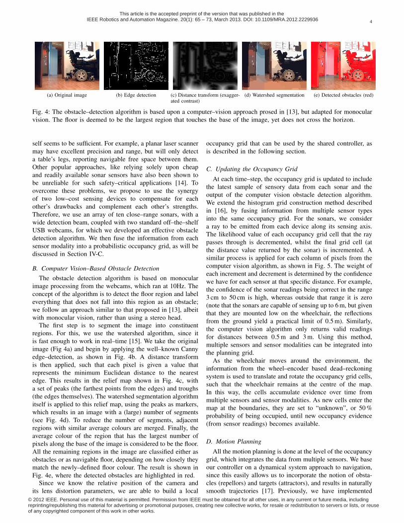
Fig. 4: The obstacle–detection algorithm is based upon a computer–vision approach prosed in [13], but adapted for monocularvision. The floor is deemed to be the largest region that touches the base of the image, yet does not cross the horizon.
self seems to be sufficient. For example, a planar laser scannermay have excellent precision and range, but will only detecta table’s legs, reporting navigable free space between them.Other popular approaches, like relying solely upon cheapand readily available sonar sensors have also been shown tobe unreliable for such safety–critical applications [14]. Toovercome these problems, we propose to use the synergyof two low–cost sensing devices to compensate for eachother’s drawbacks and complement each other’s strengths.Therefore, we use an array of ten close–range sonars, with awide detection beam, coupled with two standard off–the–shelfUSB webcams, for which we developed an effective obstacledetection algorithm. We then fuse the information from eachsensor modality into a probabilistic occupancy grid, as will bediscussed in Section IV-C.
B. Computer Vision–Based Obstacle DetectionThe obstacle detection algorithm is based on monocular
image processing from the webcams, which ran at 10Hz. Theconcept of the algorithm is to detect the floor region and labeleverything that does not fall into this region as an obstacle;we follow an approach similar to that proposed in [13], albeitwith monocular vision, rather than using a stereo head.
The first step is to segment the image into constituentregions. For this, we use the watershed algorithm, since itis fast enough to work in real–time [15]. We take the originalimage (Fig 4a) and begin by applying the well–known Cannyedge–detection, as shown in Fig. 4b. A distance transformis then applied, such that each pixel is given a value thatrepresents the minimum Euclidean distance to the nearestedge. This results in the relief map shown in Fig. 4c, witha set of peaks (the farthest points from the edges) and troughs(the edges themselves). The watershed segmentation algorithmitself is applied to this relief map, using the peaks as markers,which results in an image with a (large) number of segments(see Fig. 4d). To reduce the number of segments, adjacentregions with similar average colours are merged. Finally, theaverage colour of the region that has the largest number ofpixels along the base of the image is considered to be the floor.All the remaining regions in the image are classified either asobstacles or as navigable floor, depending on how closely theymatch the newly–defined floor colour. The result is shown inFig. 4e, where the detected obstacles are highlighted in red.
Since we know the relative position of the camera andits lens distortion parameters, we are able to build a local
occupancy grid that can be used by the shared controller, asis described in the following section.
C. Updating the Occupancy Grid
At each time–step, the occupancy grid is updated to includethe latest sample of sensory data from each sonar and theoutput of the computer vision obstacle detection algorithm.We extend the histogram grid construction method describedin [16], by fusing information from multiple sensor typesinto the same occupancy grid. For the sonars, we considera ray to be emitted from each device along its sensing axis.The likelihood value of each occupancy grid cell that the raypasses through is decremented, whilst the final grid cell (atthe distance value returned by the sonar) is incremented. Asimilar process is applied for each column of pixels from thecomputer vision algorithm, as shown in Fig. 5. The weight ofeach increment and decrement is determined by the confidencewe have for each sensor at that specific distance. For example,the confidence of the sonar readings being correct in the range3 cm to 50 cm is high, whereas outside that range it is zero(note that the sonars are capable of sensing up to 6 m, but giventhat they are mounted low on the wheelchair, the reflectionsfrom the ground yield a practical limit of 0.5 m). Similarly,the computer vision algorithm only returns valid readingsfor distances between 0.5 m and 3 m. Using this method,multiple sensors and sensor modalities can be integrated intothe planning grid.
As the wheelchair moves around the environment, theinformation from the wheel–encoder based dead–reckoningsystem is used to translate and rotate the occupancy grid cells,such that the wheelchair remains at the centre of the map.In this way, the cells accumulate evidence over time frommultiple sensors and sensor modalities. As new cells enter themap at the boundaries, they are set to “unknown”, or 50 %probability of being occupied, until new occupancy evidence(from sensor readings) becomes available.
D. Motion Planning
All the motion planning is done at the level of the occupancygrid, which integrates the data from multiple sensors. We baseour controller on a dynamical system approach to navigation,since this easily allows us to incorporate the notion of obsta-cles (repellors) and targets (attractors), and results in naturallysmooth trajectories [17]. Previously, we have implemented
© 2012 IEEE. Personal use of this material is permitted. Permission from IEEE must be obtained for all other uses, in any current or future media, including reprinting/republishing this material for advertising or promotional purposes, creating new collective works, for resale or redistribution to servers or lists, or reuse of any copyrighted component of this work in other works.
This article is the accepted preprint of the version that was published in the IEEE Robotics and Automation Magazine. 20(1): 65 – 73, March 2013. DOI: 10.1109/MRA.2012.2229936

5
Fig. 5: Each column of pixels is scanned from bottom to top,in order to detect the nearest obstacle (assuming it intersectswith the ground). The estimated distance from the wheelchairto this obstacle is a function of the (x, y) pixel coordinatesand the camera distortion parameters.
such a control strategy on a circular mobile robotic platform,which was successfully controlled by motor–disabled patientsusing a BCI [18].
With no user input, the dynamical system causes thewheelchair to move forwards and automatically avoid anyobstacles that it comes across. In practice, this is realisedby adding repellors into the dynamical system according tothe obstacle densities in the occupancy grid. Rather thansimply looking at the densities in radial directions from therobot, as was sufficient in [18]—to account for the fact thatthe wheelchair’s shape and motion is more complex thanthe circular robot—we define a set of N = 10 zones withinthe occupancy grid, as shown in Fig. 6. These zones aresplit into three sets, such that if obstacles were present inthem: Ωc = RB1, LC1, LF1, LF2 would cause clockwiserotations of the wheelchair, Ωa = LB1, RC1, RF1, RF2would cause anticlockwise rotations, and Ωn = F1, F2would not affect the rotational velocity of the wheelchair.Each zone, zi ∈ Ω, has a centre (zix, ziy) and an associatedrepulsion strength λi < 0 ∈ Λ, which is determined accordingto the position of the zone relative to the wheelchair, such thatΛ = Λc ∪Λa ∪Λn. The likelihood of there being an obstaclein each zone is ϕi ∈ [0, 1]. The rotational velocity ω is then:
ω = Kω
N∑i=1
λiSiϕi, ω ∈ [−ωmax,+ωmax], (1)
Kω =ωmax∑
λi∈Λc
|λi|(2)
Si = sgn(−zix × ziy), Si ∈ −1, 0,+1, (3)
where the constant Kω ensures that |ω| is not greater than themaximum possible rotational velocity ωmax. Note that Kω
in (1) assumes that the obstacle detection zones in Ωc andΩa, and their corresponding Λc and Λa values, are symmetric,as it is in our case. In general, this makes sense, since youwould expect symmetric behaviour from the wheelchair for
Fig. 6: The wheelchair centred in an 8 m × 8 m occupancygrid (to scale). The wheelchair obstacle detection zones arelabelled and the origin of the coordinate system is on the centreof the wheelchair’s driving axle.
symmetric stimuli1. Si simply encodes the sign (direction) ofthe resultant rotation, assuming that (zix, ziy) is the Cartesiancentre of the i-th zone, in a coordinate system whose originis in the centre of the wheelchair’s axis (as shown in Fig. 6).
Similarly, for the translational velocity, v, each zone has anassociated translational repellor, γi < 0:
v = vmax +
N∑i=1
γiϕi, v ∈ [0,+vmax]. (4)
The γi values are chosen empirically according to the dy-namics of the wheelchair and the reliability of the sensors,such that, for example, when the zone F1 reaches 50%occupancy, the wheelchair will stop. Therefore we set the γthat corresponds to zone F1 to be −2vmax, whereas the γthat corresponds to zone F2 is −0.75vmax.
When the user issues a BCI command (either a high–level turn left, or turn right), the wheelchair should turn upto a maximum of 45° in the direction indicated, dependingon the environmental context. To achieve this, an additional,corresponding virtual attractor zone is placed in the occupancygrid 1 m in front of the wheelchair, at an angle of 45° inthe direction indicated by the BCI command. This attractorzone has a corresponding ϕi = 1.0, λi = 0.5 and γi = 0.0,such that in practice it only affects the rotational velocitydynamical system. Note that λ is a positive value when actingas an attractor. The attractor remains in the dynamical system,until the wheelchair has turned up to 45° in the correspondingdirection, or a new BCI command is delivered, or until atimeout has been reached (in our case 4 seconds), at whichpoint, it is removed.
We extend the dynamical system, by exploiting the fact thatwe have a human in the loop, to enable an additional dockingbehaviour. Such a behaviour is important if the system is tobe useful outside of experimental lab conditions. Therefore,if the occupancy of zone F1 or F2 is greater than anempirically set activation threshold, KT , providing there is
1If this is not the case, one should take Kω to be the maximum valueof Kωc and Kωa, computed using Λc and Λa, respectively. However, thiswould result in asymmetric behaviour of the wheelchair.
© 2012 IEEE. Personal use of this material is permitted. Permission from IEEE must be obtained for all other uses, in any current or future media, including reprinting/republishing this material for advertising or promotional purposes, creating new collective works, for resale or redistribution to servers or lists, or reuse of any copyrighted component of this work in other works.
This article is the accepted preprint of the version that was published in the IEEE Robotics and Automation Magazine. 20(1): 65 – 73, March 2013. DOI: 10.1109/MRA.2012.2229936

6
no user input, the rotational velocity of the chair will be setto 0 rad−s. The translational velocity will still be controlledby the dynamical system, such that the wheelchair will slowdown smoothly and stop in front of the object. At any point,the user is able to deliver a left of right command to initiate anobstacle avoidance manoeuvre. If the user remains in a stateof intentional non–control, once the wheelchair has completedthe docking procedure, it will remain stationary and wait forfurther user input.
In the current implementation, the user is not able to stopthe chair in free space, instead the chair will stop whenit has docked to a potential target. In future this controlstrategy could easily be extended to include an additionalBCI command (or another biosignal, in the case of a hybridapproach) to implement an explicit stop signal.
V. EVALUATION
We demonstrate that both naıve and experienced BCIwheelchair operators are able to complete a navigation tasksuccessfully. Furthermore, unlike in P300–based systems, notonly was the user in continuous spontaneous control of thewheelchair, but the resultant trajectories were smooth andintuitive (i.e. no stopping, unless there was an obstacle, andusers could voluntarily control the motion at all times).
A. Participants
Mastering a motor imagery BCI requires extensive training,over a period of weeks or months to generate stable volitionalcontrol; it is not simply a case of putting a cap on andstarting to drive. Therefore, we have performed an initialevaluation with four healthy male subjects, aged 23–28. Allsubjects were experienced BCI users, who had participatedin at least 12 hours of online motor imagery BCI trainingand other BCI experiments over the previous few months.They all had some previous experience of driving a BCI–based tele–presence mobile robot, which requires a better levelof performance, compared to simply moving a cursor on ascreen [18]. Subjects s1 and s2 had no previous experienceof driving a BCI–controlled wheelchair, whereas subjects s3and s4 had each clocked–up several hours of driving the BCIwheelchair. Subject s1 used motor imagery of both feet toindicate turn left and of the right hand to mean turn right; allthe other subjects used left hand motor imagery to turn leftand right hand motor imagery to turn right.
B. Experiment Protocol
As a benchmark, the subject was seated in the wheelchairand was instructed to perform an online BCI session, be-fore actually driving. In this online session, the wheelchairremained stationary and the participant simply had to performthe appropriate motor imagery task to move a cursor onthe wheelchair screen in the direction indicated by a cuearrow. There was a randomized balanced set of 30 trials,separated by short resting intervals, which lasted around 4–5 mins, depending on the performance of the subject.
After the online session, participants were given 15–30minutes to familiarise themselves with driving the wheelchair
Fig. 7: Trajectories followed by subject s3 on one of themanual benchmark trials (left), compared with one of theBCI trials (right). These trajectories were reconstructed fromodometry using the independent reconstruction method [19].
using each of the control conditions: a two button manualinput, which served as a benchmark, and the BCI system.Both input paradigms allowed the users to issue left and rightcommands at an inter–trial interval of one second.
The actual task was to enter a large open–plan room througha doorway from a corridor, navigate to two different tables,whilst avoiding obstacles and passing through narrow openings(including other non–target tables, chairs, ornamental treesand a piano), before finishing by reaching a second doorwayexit of the room (as shown in Fig 7). When approaching thetarget tables, the participants were instructed to wait for thewheelchair to finish docking to the table, then once it hadstopped they should issue a turning command to continue ontheir journey. The trials were counter–balanced, such that usersbegan with a manual trial, then performed two BCI trials andfinished with another manual trial.
C. Results and Discussion
All subjects were able to achieve a remarkably good levelof control in the stationary online BCI session, as can beseen in Table I. Furthermore, the actual driving task wascompleted successfully by every subject, for every run andno collisions occurred. A comparison between the typicaltrajectories followed under the two conditions is shown inFig 7. The statistical tests reported in this section are pairedStudent’s t-tests.
A great advantage that our asynchronous BCI wheelchairbrings, compared with alternative approaches like the P300–based chairs, is that the driver is in continuous control ofthe wheelchair. This means that not only does the wheelchairfollow natural trajectories, which are determined in real–timeby the user (rather than following predefined ones, like in[5]), but also that the chair spends a large portion of the
© 2012 IEEE. Personal use of this material is permitted. Permission from IEEE must be obtained for all other uses, in any current or future media, including reprinting/republishing this material for advertising or promotional purposes, creating new collective works, for resale or redistribution to servers or lists, or reuse of any copyrighted component of this work in other works.
This article is the accepted preprint of the version that was published in the IEEE Robotics and Automation Magazine. 20(1): 65 – 73, March 2013. DOI: 10.1109/MRA.2012.2229936

7
navigation time actually moving (see Fig. 8). This is not thecase with some state–of–the–art P300–controlled wheelchairs,where the wheelchair has to spend between 60% and 80% ofthe manoeuvre time stationary, waiting for input from the user(c.f. Fig. 8 of this article with Fig. 8 of [6]).
In terms of path efficiency, there was no significant dif-ference (p = 0.6107) across subjects between the distancetravelled in the manual benchmark condition (43.1±8.9 m) andthat in the BCI condition (44.9±4.1 m). Although the actualenvironments were different, the complexity of the navigationwas comparable to that of the tasks investigated on a P300–based wheelchair in [6]. In fact, the average distance travelledfor our BCI condition (44.9±4.1 m), was greater than thatin the longest task of [6] (39.3±1.3 m), yet on average ourparticipants were able to complete the task in 417.6±108.1 s,which was 37% faster than the 659±130 s reported in [6]. Thisincrease in speed might (at least partly) be attributed to thefact that our wheelchair was not stationary for such a largeproportion of the trial time.
Across subjects, it took an average of 160.0 s longer tocomplete the task under the BCI condition (see Fig. 8,p = 0.0028). This is probably due to a combination of subjectsissuing manual commands with a higher temporal accuracyand a slight increase in the number of turning commands thatwere issued when using the BCI (c.f. Fig. 7), which resultedin a lower average translational velocity. It should be notedthat in the manual benchmark condition, the task completiontime varied slightly from subject to subject, as the experimentswere carried out on different days, where the changes inlighting conditions affected the computer vision system. Onbrighter days, some shadows and reflections from the shinywooden floor caused the wheelchair to be cautious and slowdown earlier than on dull days, until the sonars confirmed thatactually there was not an obstacle present. Therefore, it makesmore sense to do a within subjects comparison, looking atthe performance improvement or degradation on a given day,rather than comparing absolute performance values betweensubjects on different days.
From Fig. 8, it can be seen that for the inexperiencedusers (s1 and s2), there was some discrepancy in the taskcompletion time between the benchmark manual conditionand the BCI condition. However, for the experienced BCIwheelchair users (s3 and s4), the performance in the BCIcondition is much closer to the performance in the manualbenchmark condition. This is likely to be due to the fact thatperforming a motor–imagery task, whilst navigating and beingseated on a moving wheelchair, is much more demanding thansimply moving a cursor on the screen (c.f. the stationary onlineBCI session of Table I). In particular, aside from the increasedworkload, when changing from a task where one has to delivera particular command as fast as possible following a cue, to atask that involves navigating asynchronously in a continuouscontrol paradigm, the timing of delivering commands becomesvery important. In order to drive efficiently, the user needsto develop a good mental model of how the entire systembehaves (i.e. the BCI, coupled with the wheelchair) [20].Clearly, through their own experience, subjects s3 and s4 haddeveloped such mental models and were therefore able to
TABLE I: Confusion matrices of the left and right classesand accuracy for the online session, for each subject, beforeactually controlling the wheelchair.
s1 s2 s3 s4L R L R L R L R
Left class 13 2 12 3 14 1 15 0Right class 0 15 0 15 0 15 0 15
Accuracy (%) 93.3 90.0 96.7 100.0
s1 s2 s3 s40
100
200
300
400
500
600Manual benchmark condition (left bars) vs BCI condition (right bars)
Tas
k co
mpl
etio
n tim
e (s
)Subject
Time movingTime stationary
Fig. 8: The average time required to complete the task for eachparticipant in a benchmark manual condition (left bars) andthe BCI condition (right bars). The wheelchair was stationary,waiting user input, only for a small proportion of the trial.
anticipate when they should begin performing a motor imagerytask to ensure that the wheelchair would execute the desiredturn at the correct moment. Furthermore, they were alsomore experienced in refraining from accidentally deliveringcommands (intentional non–control) during the periods wherethey wanted the wheelchair to drive straight forwards andautonomously avoid any obstacles. Conversely, despite thegood online BCI performance of subjects s1 and s2, theyhad not developed such good mental models and were lessexperienced in controlling the precise timing of the delivery ofBCI commands. Despite this, the use of shared control ensuredthat all subjects, whether experienced or not, could achieve thetask safely and at their own pace, enabling continuous mentalcontrol over long periods of time (> 400 s, almost 7 minutes).
VI. CONCLUSION
In this article, we have seen how a viable brain–actuatedwheelchair can be constructed by combining a brain computerinterface with a commercial wheelchair, via a shared controllayer. The shared controller couples the intelligence and de-sires of the user with the precision of the machine. We havefound that this enabled both experienced and inexperiencedusers alike to safely complete a driving task that involveddocking to two separate tables along the way.
Furthermore, we have compared our results with those pub-lished on other state–of–the–art brain–controlled wheelchairsthat are based on an alternative synchronous stimulus–drivenprotocol (P300). Our asynchronous motor–imagery approach
© 2012 IEEE. Personal use of this material is permitted. Permission from IEEE must be obtained for all other uses, in any current or future media, including reprinting/republishing this material for advertising or promotional purposes, creating new collective works, for resale or redistribution to servers or lists, or reuse of any copyrighted component of this work in other works.
This article is the accepted preprint of the version that was published in the IEEE Robotics and Automation Magazine. 20(1): 65 – 73, March 2013. DOI: 10.1109/MRA.2012.2229936

8
gives users greater flexibility and authority over the actualtrajectories driven, since it allowed users to interact with thewheelchair spontaneously, rather than having to wait for exter-nal cues as was the case with [5], [6]. Moreover, combiningour BCI with a shared control architecture allowed users todynamically produce intuitive and smooth trajectories, ratherthan relying on predefined routes [5] or having to remainstationary for the majority of the navigation time [6].
Although there was a cost in terms of time for inexperiencedusers to complete the task using the BCI input compared with amanual benchmark, experienced users were able to completethe task in comparable times under both conditions. This isprobably as a result of them developing good mental modelsof how the coupled BCI–shared control system behaves.
In summary, the training procedure for spontaneous motorimagery–based BCIs might take a little longer than thatfor stimulus–driven P300 systems, but ultimately it is veryrewarding. After learning to modulate their brain signalsappropriately, we have demonstrated that both experienced andinexperienced users were able to master a degree of continuouscontrol that was sufficient to safely operate a wheelchair ina real world environment. They were always successful incompleting a complex navigation task using mental controlover long periods of time. One participant remarked that themotor–imagery BCI learning process is similar to that ofathletes or musicians training to perfect their skills: when theyeventually succeed they are rewarded with a great sense ofself–achievement.
VII. THE FUTURE
We have already begun evaluating our brain–actuatedwheelchair with motor–disabled patients in partnership withmedical practitioners and rehabilitation clinics, but this is anarduous process that will take significantly longer than theinitial trials with healthy subjects. This is for a number ofreasons, not least that patients tend to take part in fewersessions per week and generally tire more quickly than healthyparticipants. This leads us to another one of the excitingnew challenges for the future of such shared control systems.Since each user’s needs are not only different, but also changethroughout the day (e.g. due to fatigue, frustration etc.), it isnot sufficient that a shared control system offers a constantlevel of assistance. Furthermore, if this assistance is not well–matched to the user, it could lead to degradation or loss offunction. Therefore we are developing shared control systemsthat adapt to the user’s evolving needs, given not only theenvironmental context, but also the state of the user. This willallow people to use intelligent assistive devices in their day–to–day lives for extended periods of time.
VIII. ACKNOWLEDGEMENT
This work is supported by the European ICT Project TOBI(FP7-224631) and the Swiss National Science Foundationthrough the NCCR Robotics. This paper only reflects theauthors’ views and funding agencies are not liable for anyuse that may be made of the information contained herein.
REFERENCES
[1] A. van Drongelen, B. Roszek, E. S. M. Hilbers-Modderman,M. Kallewaard, and C. Wassenaar, “Wheelchair incidents,” Rijksinstituutvoor Volksgezondheid en Milieu RIVM, Bilthoven, NL, Tech. Rep.,November 2002, accessed Februaury, 2010. [Online]. Available:http://hdl.handle.net/10029/9183
[2] A. Frank, J. Ward, N. Orwell, C. McCullagh, and M. Belcher, “Intro-duction of a new NHS electric-powered indoor/outdoor chair (EPIOC)service: benefits, risks and implications for prescribers,” Clinical Reha-bilitation, no. 14, pp. 665–673, 2000.
[3] R. C. Simpson, E. F. LoPresti, and R. A. Cooper, “How many peoplewould benefit from a smart wheelchair?” Journal of RehabilitationResearch and Development, vol. 45, no. 1, pp. 53–71, 2008.
[4] T. Carlson and Y. Demiris, “Collaborative control for a roboticwheelchair: Evaluation of performance, attention, and workload,” IEEETransactions on Systems, Man, and Cybernetics, Part B: Cybernetics,vol. 42, no. 3, pp. 876–888, 2012.
[5] B. Rebsamen, C. Guan, H. Zhang, C. Wang, C. Teo, M. Ang, andE. Burdet, “A brain controlled wheelchair to navigate in familiarenvironments,” IEEE Transactions on Neural Systems and RehabilitationEngineering, vol. 18, no. 6, pp. 590–598, dec. 2010.
[6] I. Iturrate, J. Antelis, A. Kubler, and J. Minguez, “A noninvasive brain-actuated wheelchair based on a P300 neurophysiological protocol andautomated navigation,” IEEE Transactions on Robotics, vol. 25, no. 3,pp. 614–627, june 2009.
[7] J. d. R. Millan, F. Galan, D. Vanhooydonck, E. Lew, J. Philips, andM. Nuttin, “Asynchronous non-invasive brain-actuated control of anintelligent wheelchair,” in Proc. 31st Annual Int. Conf. IEEE Eng. Med.Biol. Soc., 2009, pp. 3361–3364.
[8] J. d. R. Millan, F. Renkens, J. Mourino, and W. Gerstner, “Noninvasivebrain-actuated control of a mobile robot by human EEG,” IEEE TransBiomed Eng, vol. 51, no. 6, pp. 1026–1033, 2004.
[9] F. Galan, P. W. Ferrez, F. Oliva, J. Guardia, and J. d. R. Millan, “Featureextraction for multi-class BCI using canonical variates analysis,” in IEEEInt Symp Intelligent Signal Processing, 2007.
[10] J. d. R. Millan, P. W. Ferrez, F. Galan, E. Lew, and R. Chavarriaga,“Non-invasive brain-machine interaction,” Int J Pattern Recognition andArtificial Intelligence, vol. 22, no. 5, pp. 959–972, 2008.
[11] S. Perdikis, H. Bayati, R. Leeb, and J. d. R. Millan, “Evidenceaccumulation in asynchronous BCI,” International Journal of Bioelec-tromagnetism, vol. 13, no. 3, pp. 131–132, 2011.
[12] G. Lucas, “A tutorial and elementary trajectory model forthe differential steering system of robot wheel actuators,” TheRossum Project, Tech. Rep., May 2000. [Online]. Available:http://rossum.sourceforge.net/papers/DiffSteer/
[13] E. Fazl-Ersi and J. Tsotsos, “Region classification for robust floordetection in indoor environments,” in Image Analysis and Recognition,M. Kamel and A. Campilho, Eds. Springer Berlin / Heidelberg, 2009,vol. 5627, pp. 717–726.
[14] T. Dutta and G. Fernie, “Utilization of ultrasound sensors for anti-collision systems of powered wheelchairs,” IEEE Transactions on NeuralSystems and Rehabilitation Engineering, vol. 13, no. 1, pp. 24–32,March 2005.
[15] S. Beucher, “The watershed transformation applied to image segmenta-tion,” Scanning Microscopy International, vol. 6, pp. 299–314, 1992.
[16] J. Borenstein and Y. Koren, “The vector field histogram - fast obstacleavoidance for mobile robots,” IEEE Transactions on Robotics andAutomation, vol. 7, no. 3, pp. 278–288, 1991.
[17] G. Schoner, M. Dose, and C. Engels, “Dynamics of behavior: Theory andapplications for autonomous robot architectures,” Robot. AutonomousSyst., vol. 16, pp. 213 – 245, 1995.
[18] L. Tonin, T. Carlson, R. Leeb, and J. d. R. Millan, “Brain-controlledtelepresence robot by motor-disabled people,” in Proc. Annual Interna-tional Conference of the IEEE Engineering in Medicine and BiologySociety EMBC 2011, 2011, pp. 4227–4230.
[19] S. ten Hagen and B. Krose, “Trajectory reconstruction for self-localization and map building,” in Proceedings of the IEEE InternationalConference on Robotics and Automation, vol. 2, 2002, pp. 1796 – 1801vol.2.
[20] D. Norman, The Design of Everyday Things. Doubleday Business,2002.
© 2012 IEEE. Personal use of this material is permitted. Permission from IEEE must be obtained for all other uses, in any current or future media, including reprinting/republishing this material for advertising or promotional purposes, creating new collective works, for resale or redistribution to servers or lists, or reuse of any copyrighted component of this work in other works.
This article is the accepted preprint of the version that was published in the IEEE Robotics and Automation Magazine. 20(1): 65 – 73, March 2013. DOI: 10.1109/MRA.2012.2229936