computer-controlled robotic marine coatings application system
TRANSCRIPT

Computer-Controlled Robotic Marine Coatings Application System
David Tolliver (Lead Author) Steve Morton
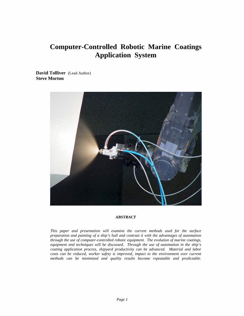
ABSTRACT This paper and presentation will examine the current methods used for the surface preparation and painting of a ship’s hull and contrast it with the advantages of automation through the use of computer-controlled robotic equipment. The evolution of marine coatings, equipment and techniques will be discussed. Through the use of automation in the ship’s coating application process, shipyard productivity can be advanced. Material and labor costs can be reduced, worker safety is improved, impact to the environment over current methods can be minimized and quality results become repeatable and predictable.
Page 1

BODY OF KNOWLEDGE The ideas and design goals discussed in this paper come from a collaborative synthesis of over seventy-five years of experience involving the time-honored craftsmanship of the yacht coatings application process, computer numerical control (CNC) robotic integration along with complex real time computer systems used for data acquisition, simulation and scientific research. Please review the biographical entries in the appendix for more detail. Nomenclature used is clarified at first use. A STATUS OF THE MARINE COATINGS INDUSTRY When compared to many industries, the field of marine coatings is quite unique. Obviously, there are a number of sciences involved if one considers the actual coatings themselves. However, if the discussion is limited to just the marine coatings application process, it could be successfully argued that the adaptation of technology in advancing coatings application methods is lagging other industries. Automotive companies in the Far East began the adaptation of robotics almost forty years ago as a matter of establishing competitive advantage in their strategy to enter the world market. For the domestic auto makers, it was a matter of survival. Robotics were first introduced to the domestic automotive industry well over twenty-five years ago. Toyota quickly became the third largest manufacturer behind GM and Ford. Constant attention to improvements in robotic integration and operation has provided advancements in automotive manufacturing productivity to the extent that now there is less concern over domination in a marketplace as a standard of quality has emerged; especially where the application of automotive coatings is concerned. One might say that this advancement through the adaptation of robotic technologies has “leveled the playing field.” Adaptation of robotics for the marine coatings industry remains a tricky proposition. While the technology to do so certainly exists, it has not been achieved. That may be more a function of apprehension of the unknown or presumed costs associated with the capital expense of re-tooling rather than the exercise of practical judgment and an honest calculation for the return on investment (ROI) for such a system.
What follows in this paper is an examination of the current methods employed in the yacht coatings application process. It will contrast traditional methods with what has been achieved by the adaptation of computer-controlled robotics, developed to automate the coatings process. The yacht coatings system discussed is commercially available today. One can also consider the similarities within the process between marine coatings for yachts with military and commercial applications where coatings application to large amounts of surface areas can be greatly enhanced through automation. A development project is under way for a commercial/military surface preparation and coatings application system employing computer-controlled robotic automation. (Please refer to the Appendix, Charts 1 and 2.) TODAY’S MARINE COATINGS METHODOLOGY Visiting any shipyard engaged in ship’s repair work or new builds will provide a glimpse of the laborious nature of the marine coatings process. The perspectives of the process range from the vessel owner wondering when the job will be done and how much it will cost, to shipyard management wondering how they can cut costs and improve productivity and profits and to the laborer wondering if there is a better way to get the job done. The fact is, to properly fair and paint a yacht requires that each square foot above the waterline be gone over by hand multiple times to properly apply a complete coatings system. Paint scaffolding must be constructed around the work area itself in order to perform the various steps in the coatings process. This by itself is a difficult task and if not done correctly, would provide unsafe conditions that could prove to be very costly before the job is done. Assuming that all paint-able surfaces are prepared, primed and ready for the coatings process to begin, the next step in yacht coatings involves mapping the surfaces of the hull to determine low spots for the fairing process. This is typically done by a team of workers holding a long straight edge (wood or aluminum batten), one at either end with a third worker marking the low spots on the surface relative to the straight edge. Low spots are later filled with fairing material. After the surfaces are mapped by hand, workers mix two-part epoxy fairing materials and begin the process of filling in the lows identified in the mapping step. Once this step is complete, additional fairing material is troweled on to help add shape and
Page 2
continuity to the surface. By accident, ignorance or with intent, the materials could be incorrectly mixed creating an opportunity for early failure of the coatings system. The exact manufacturer’s mixing instructions are not always followed. 100% solids epoxy fairing material is sometimes ”juiced” with solvents to make it trowel onto the surface easier or a worker may have added solvents to extend the “pot life” of the mixed epoxy materials. Either way, solvents are being used which greatly increases the chances for failure through solvent entrapment. Even without the solvents, an inexperienced worker may inadvertently trap excessive air in the fairing material, through improper mixing or troweling, again producing an opportunity for early failure of the coating system. The next step involves perhaps the most laborious activity in the yacht coatings process: Long-Boarding. In order to develop smooth surfaces from the fairing process, long sanding boards are used. Two or more workers may work as a team to push a long-board back and forth across the surface, first with heavy grit sandpaper to shape the fairing then with finer grit to smooth the surface in preparation for primer coats. A last step in shaping and sanding is to remove the dust which has settled over the work areas and scaffolding. Using vacuums and tack cloths, the workers must clean the area. With the area cleaned, the work surfaces are ready to be painted. The application of the correct and compatible primers and top coats must be done as uniformly as possible to insure good coverage (dry film thickness) and the desirable result. The talent of the workers involved is variable and may in their own way inadvertently induce failures either by their methods or their equipment. Poor adhesion or de-lamination can occur if application temperatures and time intervals are not maintained. Again, incorrect mixing of the materials and over-use of solvents will also result in a failed coatings system. To achieve a “mirror-like” surface on a yacht is not impossible, but every worker involved must make sure each step of the process is performed correctly, on time and without failing to follow instructions. Shortcuts in the process may bring the job to an end sooner but will also, more than likely, bring the job back sooner for warranty failures. PRODUCTIVITY, SAFETY AND ENVIRONMENTAL CONCERNS When considering today’s methodologies for the marine coatings process, the more labor intensive the job may be, the more likely it is for mistakes to be made. Productivity suffers at this point in that
rework has to be performed. An experienced and competent crew can be very productive relative to manual methods but not as productive when compared to the use of automation. Asking a painter to hold a High Volume Low Pressure (HVLP) spray gun connected to a plural component mixing system, possibly with heated fluid lines and consistently apply 10 mil of thickness of the epoxy coatings while climbing around scaffolding for more than two hours at a time is not practical. Training that painter to program and operate a system that has automated that process would be far more productive and would yield the desired, uniform result. Scaffolding and motorized high-reach man-lifts are commonly used to place the workers close to the work surface. The U.S. Department of Labor Occupational Safety & Health Administration (OSHA) reports that over 45,000 accidents and 50 deaths occur each year where industrial construction scaffolding is in use. Eliminating the use of scaffolding in the coatings process immediately makes for a safer workplace. A by-product of the marine coatings process is the release of Hazardous Air Pollutants (HAPs) or Volatile Organic Compounds (VOCs) into the atmosphere, and sometimes into the groundwater and ecosystems. Regulatory compliance may have a calculable expense but the impact on the environment may remain an unknown for years. Costs can include draping adjacent areas, collection and treatment systems but may also include regulatory fines or litigation. ADAPTATION OF TECHNOLOGY Without question, increased productivity and efficiency are attainable through the automation of a process. As technology continues its evolutionary pace, those that harness it will enjoy its advances. Automation in the marine coatings process is long over due. Few attempts have been made but until now, no one company has integrated the technology necessary to automate the yacht fairing and coatings process. Patented computer-controlled robotic technology exists today that brings the efficiencies of automation to the marine coating process. Similar to the automotive industry, the integration of computer-controlled robotics to perform a labor intensive process provides predictable uniformity and works tirelessly while changing the marine coatings application process. What follows in this paper is a discussion of such technology in a configuration that can perform the complete yacht coatings process. For the yacht
Page 3
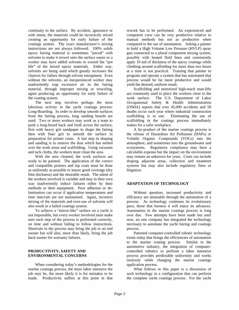
system, twin robots traverse stationary, parallel motion tracks installed and laser-leveled for accuracy. Depending upon the size vessel (ideally 50 meters and above), 7 or 9-axis capabilities are employed. Commercial/military applications would typically utilize a mobile high-reach system, depending upon the available space in the work area. LASER TOPOGRAPHIC MAPPING At the heart of the track-mounted, multi-axis robotic yacht system is a CDRH Class IIIb laser tool, which mounts on the robot arm and incorporates vision sensors to accurately scan objects at high speed. The laser is actually collecting 3D measurement data that is processed further to develop the tool paths for subsequent steps in the coatings process. The CDRH, Center for Devices and Radiological Health, classifies lasers based on the power range the laser operates in. Associated with the different laser classifications are varying levels of safety precautions to be taken for safe operation. The current operational laser mapping capability utilizes a scanning beam 800 mm long that collects 512 points of data per scan and moves across the work surface at a rate of 50 scans per second. In functional terms, the laser mapping system, set up to function with these parameters, is capable of mapping the hull surface of a 50 meter yacht in a single day. To perform the mapping, and other process steps, the vessel remains stationary and the robot performs its functions while moving on a stationary track beside the vessel. What is most important about the laser mapping system is that the data captured is processed by the system software application and rendered into a CAD file with control data that drives the other steps of the coatings process. Figure 1 shows multiple scanned profiles that make up the measured point cloud data.
Figure 1.
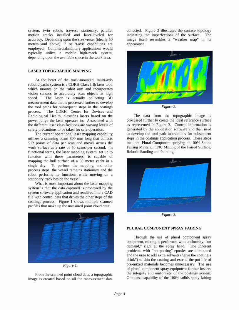
From the scanned point cloud data, a topographic image is created based on all the measurement data
collected. Figure 2 illustrates the surface topology indicating the imperfections of the surface. The image itself resembles a “weather map” in its appearance.
Figure 2.
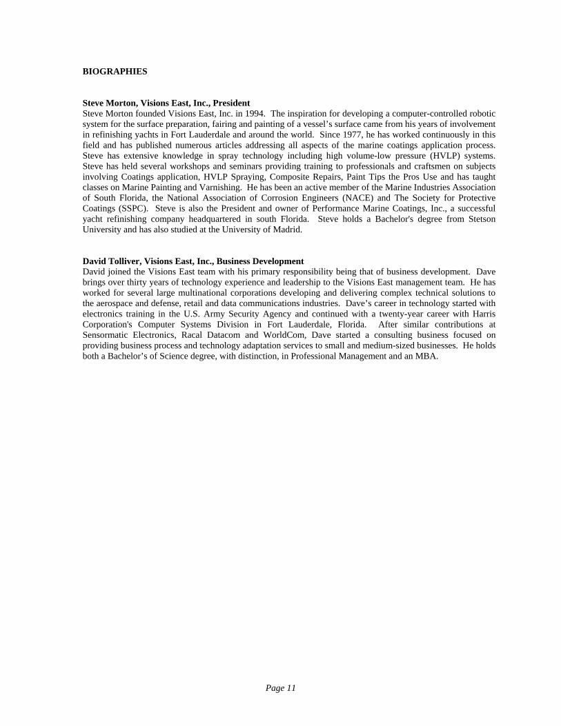
The data from the topographic image is processed further to create the ideal reference surface as represented in Figure 3. Control information is generated by the application software and then used to develop the tool path instructions for subsequent steps in the coatings application process. These steps include: Plural Component spraying of 100% Solids Fairing Material, CNC Milling of the Faired Surface, Robotic Sanding and Painting.
Figure 3.
PLURAL COMPONENT SPRAY FAIRING Through the use of plural component spray equipment, mixing is performed with uniformity, “on demand,” right at the spray head. The inherent problems with “hot-potting” epoxies are eliminated and the urge to add extra solvents (“give the coating a drink”) to thin the coating and extend the pot life of pre-mixed materials becomes unnecessary. The use of plural component spray equipment further insures the integrity and uniformity of the coatings system. One-pass capability of the 100% solids spray fairing
Page 4

material can reach 15-19 mm or 5/8 to 3/4 of an inch. Solvents are not used thereby avoiding solvent entrapment, a big cause of coatings failures and shrinkage of the material due to the evaporation and release of VOCs. To maintain the proper viscosity for pumping and spraying the epoxy compounds, heated fluid lines and drum heaters are employed. Below, figures 4 through 6 show the pumping system, the spray tip and a one pass sample of the sprayed fairing materials. The optimal milling window will typically occur between 18 to 72 hours of curing, depending upon the ambient room temperatures. As with all coatings application, the work area environmental conditions have to be taken into account for best results.
Figure 4. Plural Component Spray Pump System
Figure 5. P.C. Spray tip applying single pass of Robotically Applied Fairing Compound
Figure 6. Cross-section of single-pass Robotically
Applied Fairing Compound
Shown is a one-pass sample 15 to 19 mm (5/8 to 3/4 inch)
thickness
CNC MILLING OF THE FAIRED SURFACE The robot arm is next fitted with a tool designed for robotic milling. Attached to the spindle motor on the tool is a hollow core high speed milling bit equipped with vacuum lines Utilizing the control data generated during the topographic mapping step, the cutting bit is moved along the surface to cut the “ideal” shape of the hull from the sprayed fairing material as depicted by the processed CAD file. The bit used is a 2 inch (5 cm) hollow core bit that allows for vacuum evacuation of the milled debris. The combination of a hollow core and the ventilated tip with vacuum dust extraction maintains a cooler working temperature that extends the life of the milling bit. Typically, only a few millimeters will actually be milled from the surface that was optimized during the laser scanning step. The result is a smooth, clean surface that will next be sanded to establish a profile that the primer coats will adhere to. While a single sanding head is shown below in figure 8, for larger jobs, an array of multiple sanding heads would be configured and guided across the work surface by the control data initially collected and processed.
Page 5

Figure 7. High speed CNC milling of Robotically
Applied Fairing Compound
Figure 8. Robotic sanding with vacuum-through-
head sanding tool in single-head configuration
ROBOTIC SPRAY PAINTING The last process step is where automation clearly has the edge in providing uniformity in the coatings application process. Manually holding a spray gun and moving it over the work surface such that the best possible finish is achieved over an extended period of time is virtually impossible. That is to say that to expect a painter to hold his equipment at the same stand-off distance, the same angle, move it at the same speed allowing the same volume of material to be applied uniformly on the surface is a difficult task. That is why, within painting crews, there are those that are recognized as “expert” craftsmen and those that are not. The individual lacking the expertise may never reach expert capability but may
be a great pot or hose man in the traditional paint crew. Automation of the spraying step not only provides efficiency in the process, it also provides uniform quality in the process. If the paint specification calls for a 6 mil thickness, it can be dialed in and maintained throughout the complete surface coating. If the paint specification requires the use of 80% high solids material and a dry film thickness of say 8 mils, then the robotic spray system’s computer would be programmed for the paint specification and will guide the equipment to spray 10 mil wet film thickness to provide the uniformity desired of an 8 mil dry film thickness avoiding excess material waist in the process. The choice of paint mixing and spray equipment is not limited but the use of Plural Component mixing combined with a High Volume Low Pressure (HVLP) spray gun is an excellent system for producing yacht-quality finishes. This combination allows for a very high transfer efficiency while maintaining appropriate painting attributes such as overlap and wet edge retention. High transfer efficiency spray equipment minimizes overspray, is friendlier to the environment and safer for the workers involved. Plural component mixing as opposed to “hot-potting” is desirable in that the coatings material is mixed at the spray tip in a precise method. Using automation, the mixture rate is set up for continuous uniformity and material waste is minimized if not altogether avoided. Airless and air-assisted airless and electrostatic spray systems can be utilized as well, typically in a commercial/military application where high gloss and an “automobile-quality” finish are not required. An optional overspray capture system can also be engineered to further address potential environmental concerns.
Figure 9. Robotic spray system with HVLP gun
Page 6

Figure 10. Robotic spray system with HVLP gun minimizes overspray for high transfer efficiency
EVOLUTION OF AN IDEA One of the most desirable attributes of the system design is the integration and use of the computer system. The computer is used not just to operate and guide the tools of the system over the work surface but to also monitor and record the various streams of data that are generated constituting a verification of the complete coatings process. Monitoring the material mixing steps can include barcode verification for lot, batch, color, Material Safety Data Sheet (MSDS), project or date codes, etc., further limiting potential mistakes in the coatings application process. A fully integrated system may feature a cache of real-time measurement instruments to read and monitor coatings thickness, chlorides and even substrate verification, making the system even more comprehensive. Ultrasonic thickness gauges could be adapted and used to verify substrate integrity prior to application. Wet film thickness measurement can be utilized to verify in real time that the coatings specification is being met. Adapting computer-controlled robotic methods for large commercial/military ships and similar applications, incorporating both surface preparation and coatings application in one system has already taking shape. Through the lessons learned in developing and delivering the yacht system solution to a first customer, arguably a more difficult technological challenge, the desired capabilities of a commercial/military system combining surface preparation and coatings application in one system are certainly within reach and under development. Figure 11 shows a wheeled robotic manipulator that has been modified with advanced hydraulics and servos. A shot-blasting unit is mounted in this illustration as a surface preparation method at the end
of the 20 meter arm. The integration of commercially successful Ultra High Pressure Waterblasting equipment provides a more generally accepted surface preparation method. The spray system design incorporates years of painting expertise in delivering uniform coating application at speeds unattainable by manual methods. An accomplished painter may be able to spray up to 2,000 square feet of coatings per hour for a short time but could not be expected to maintain that high rate of production over the course of a day and maintain uniformity. Utilizing computer-controlled automation, rates above 5,000 square feet per hour can be attained, consistently with predictable, continuous uniformity. The systems for automated guidance and surface positioning require adaptation and testing of visions systems that are commercially available and certainly represent a level of effort to incorporate and perfect. Meanwhile, work towards demonstrating coatings capability continues. (Please see Chart 2 in the Appendix for a detailed process flow.)
Figure 11. Mobile Robot for Surface Preparation
and Coatings Application BEYOND THE HORIZON The Wright Brothers were credited with the first manned flight in 1903. Their first design was a fixed-wing aircraft that was powered by a small engine. Over time, their designs evolved to where today we have super-sonic aircraft and space shuttles that transport man to and from outer-space. The challenge to utilize the technology discussed for the marine coatings application process and have it treat more than exterior flat surfaces, is an incumbent responsibility, and will soon be achieved. For now, integrating additional technology that has already
Page 7

been proven in other industries will provide a source of continued functional improvement for the automated marine coatings application system.
The next frontier for consideration might be the
automated robotic application of marine coatings on a vessel’s superstructure, internal tanks or even double-bottom areas. Difficult challenges are ahead, but technology will enable success.
SUMMARY The technology available to force an evolution in
the marine coatings application process has already proven itself in the automotive and aerospace industries for many years. 2004 is the year automation of the marine coatings application process has taken its first steps with a customer delivery of the first patented system. The arcane “craftsmanship” methods still in use today will always have its limitations and variations because of the inefficient manual effort component but will continue to evolve. We appreciate the beauty of craftsmanship but when technology provides a clearly superior method for performing a process, adherence to old methods cease to be advantageous. Especially when the savings achieved in all areas of concern, from manpower and materials to safety, warranty and reliability combine to provide substantial savings in time and expense.
Ongoing advancements in coatings formulas
along with a desire for higher efficiency, better quality and repeatable uniformity, have driven the technological advancements that have been discussed and are now being made today in the marine coatings application process. The marine coatings industry is ready to evolve. The question is - “are you?”
Page 8

APPENDIX - CHART 1
Step 3
Epoxy Spray FairingOver the Hull
Step 2
Class IIIb LaserTopogrphic
Mapping Process
Step 3Plural Component
100% SolidsEpoxy Spray Fairing
Fill Lows
Step 4
MillingVacuum-Through-Head
Step 1
Surface Preparation(as required)
Media Reclamation
Step 5
SandingMulti-Head Array
Vacuum-Through-Head Step 6Painting
Plural ComponentHighest
Transfer Efficiency
Yacht SystemProcess Flow
Process FlowYacht Process
10/2003Visions East, Inc.
Point CloudData
CAD ReferenceFile
OptionalMeasurement
SystemsAudioguaging, Laser
Wet Film Thickness, etc.
Page 9

APPENDIX - CHART 2 COMMERCIAL / MILITARY SYSTEM
s.
Step 2Robot
Programming
Step 3Surface Preparation
UHP WaterblastingVacuum Reclamation
Step 4Coatings Application
Highest TransferEfficiency System Optional
MeasurementA. Coatings Thickness
(Ultrasonic, Laser)B. Audio-gauging ofconstruction material
OptionalMaterial Verification
PDF417 Barcode
Step 1Surface Detection
Point to Pointor Laser Sensor
OptionalChloride
MeasurementSystem
OptionalWaste Treatment
System
OptionalOverspray Capture
System
“Lean Sh pbu ding”i il
Material Verification:• Type, Lot, Color of Coating • Date Codes, Project Codes, Inventory Control• MSDS Information
“Limiting Coatings Mistakes”
Measurement:• Real Time Data Acquisition• Coatings Thickness• Residual Chlorides• Detection of “Holidays”• Ship’s Hull Construction Integrity
“Verifying Process Quality”
Capture Sub-Systems:• Waterblasting Debris Capture & Water Treatment• Overspray Capture and HAP/VOC Removal
“Protecting the Environment”
Coatings Application:• Exceed 10,000 Sq.Ft./Hour• Exceed 90% Transfer Efficiency
“Enhanced Productivity”
Commercial/Military Robotic Coatings System
Page 10
BIOGRAPHIES Steve Morton, Visions East, Inc., President Steve Morton founded Visions East, Inc. in 1994. The inspiration for developing a computer-controlled robotic system for the surface preparation, fairing and painting of a vessel’s surface came from his years of involvement in refinishing yachts in Fort Lauderdale and around the world. Since 1977, he has worked continuously in this field and has published numerous articles addressing all aspects of the marine coatings application process. Steve has extensive knowledge in spray technology including high volume-low pressure (HVLP) systems. Steve has held several workshops and seminars providing training to professionals and craftsmen on subjects involving Coatings application, HVLP Spraying, Composite Repairs, Paint Tips the Pros Use and has taught classes on Marine Painting and Varnishing. He has been an active member of the Marine Industries Association of South Florida, the National Association of Corrosion Engineers (NACE) and The Society for Protective Coatings (SSPC). Steve is also the President and owner of Performance Marine Coatings, Inc., a successful yacht refinishing company headquartered in south Florida. Steve holds a Bachelor's degree from Stetson University and has also studied at the University of Madrid. David Tolliver, Visions East, Inc., Business Development David joined the Visions East team with his primary responsibility being that of business development. Dave brings over thirty years of technology experience and leadership to the Visions East management team. He has worked for several large multinational corporations developing and delivering complex technical solutions to the aerospace and defense, retail and data communications industries. Dave’s career in technology started with electronics training in the U.S. Army Security Agency and continued with a twenty-year career with Harris Corporation's Computer Systems Division in Fort Lauderdale, Florida. After similar contributions at Sensormatic Electronics, Racal Datacom and WorldCom, Dave started a consulting business focused on providing business process and technology adaptation services to small and medium-sized businesses. He holds both a Bachelor’s of Science degree, with distinction, in Professional Management and an MBA.
Page 11