brb900 gps telemetry system
TRANSCRIPT

BRB900 GPS Telemetry System May 10, 2011 Version 0.05
1. Overview: The BRB900 Telemetry System consists of a GPS receiver and RF transmitter paired with a matching RF receiver. The
GPS/Transmitter is placed in the object to be tracked, and the receiver is located at the base station. The GPS computes the position
of the object being tracked and transmits this information over an RF data link. The receiver decodes the data, which shows, in real
time, the precise location of the object being tracked.
2. Quick Start Guide: All BRB900 transmitters and receivers arrive preconfigured and ready to run OUT OF THE BOX, no configuration
necessary. Simply apply power to the transmitter and make sure the GPS module has a clear view of the sky (initial lock
times may exceed 15 minutes). Power is turned on/off by installing/removing the small 2-pin jumper to the right of the
3-pin battery connector). The battery connects to the GPS transmitter via the 3-pin blue connector, and should be left
connected at all times (except when charging). See section 15 for a description of the different jumpers and headers.
Plug the receiver into the USB port, or turn on the power switch for the LCD version.
For the USB version, you will also have to run some terminal emulation (e.g. Hyperterm) program to view the GPS data
stream. Baud rate should be set to 9600-8-N-1.
For those who want to know more about configuring and using your BRB900 GPS devices, read on.
3. Configurations:
3.1 Configuration #1 This basic setup consists of the entry level transmtiter and receiver. Data from the GPS receiver is forward
onto the wireless link. The matching receiver contains a USB interface, and reports everything it recives from
the wireless link. Multiple transmitters can be enabled at the same time, but will only be decoded by the
receiver their destination addressess match. If multiple transmitters are configured with the same destination

address, the receiver will echo all received packets. It is not possible to determine which packets were sent from which receiver.
The selection and rate of transmitted NMEA sentences from the GPS module are configured using the “Trimble Studio” software.
If many NMEA sentences are enabled for transmit every second, battery life wil be at a minimum and bandwidth usage at a
maximum since the transmitter will be active for much of the time.
The networking parameters of the receiver are updated with the X-CTU software via the USB port. It is not
possible to update the networking parameters on the transmitter unless the module is removed and transferred
temporarily into the receiver.
3.2 Configuration #2
This is the same as the the previous configuration, but uses the enhanced, or “Smart” version of the
transmitter. This transmitter contains a microcontroller, G-switch, and non-voltalile memory. The G-switch
is used to detect he beginning of the flight. This information will be used to stop the data logging when the
memory fills. Up to 1200 data points can be stored at a user defined rate for later download to a .kml file
viewable in Google Earth.
The microcontroller can also assemble a “summary” packet from the NMEA data which is then sent over the
RF link along with the raw NMEA sentences. In addition to the summarized data, the packet contains a unique identifier. If
multiple transmitters are configured with the same destination address, the receiver will echo all received
packets. The unique identifier in the summary packets can be used to determine the source of the
transmitted data. The source of the NMEA data strings, however, can not be determined. Transmisson of
both the NMEA strings and summary packets can be in individually disabled.
Battery usage and bandwidth can be minimized by disabling the transmission of raw NMEA data, and configuring the Summary
packet to be transmitted intermittenttly (every 5 seconds, for example).
3.3 Configuration #3
The third configuration is like #1, but adds the enhanced LCD receiver. If the $GPGGA NMEA sentence is
enabled, the Latitude, longitude, altitude HDOP (Horizontal Dilution of Precision) and number of satellites
locked will be displayed on the LCD screen. Other NMEA sentences can be enabled as well, using the
Trimble software, and all received data will be sent to the USB port.
The networking parameters of the receiver are updated with the X-CTU software via the USB port. It is not
possible to update the networking parameters on the transmitter unless the module is removed and
transferred temporarily into the transmitter.
Figure 2:
Configuration #2
Figure 1
Configuration #1
Figure 3 Configuration #3

3.4 Configuration #4
The final configuration uses the enhance LCD receiver and Smart transmitter. As in configuration #3, the
GPGGA sentences can be displayed on the LCD screen. Additionally, the Receiver can be configured to
decode and display the summary packets. Sent by the smart transmitter. In addition to the information
described in configuration #3, the summary packets contain VDOP (Vertical Dilution of Precision) as well as
the unique identifier and the battery voltage of the transmitter. When the Receiver is first powered on, it
looks for the first summary packet and remembers the unique identifier. Subsequent summary packets
from other transmitters will be ignored. As with the other receivers, all data (NMEA and Summary
packets) that match the destination address will be sent to the USB port.
The networking paramters of the receiver are updated with the X-CTU software via the USB port. The
networking parameters of the transmitter may be modified using the “BRB900 Communicator”.
4. BRB 900 Transmitter The base level transmitter consists of a GPS receiver, 900 MHz spread spectrum transmitter, and battery regulator circuitry.
Power is supplied via J4 and J5. The battery is connected via J4 and can be left in indefinitely. While power is applied to J4, the GPS
module’s battery backup circuit is powered on and keeps the almanac and ephemeris up to date, allowing for quicker lock times.
Jumper J5 may be used to turn the rest of the board ON and OFF.
The LED will blink when GPS lock is obtained.
The rate and selection of NMEA sentences are controlled by directly programming the GPS receiver using the Trimble Studio
program. Access to the GPS receiver is provided via J2 and pictured below: The default setup transmits the $GPRMC sentence once
every 5 seconds.
The RF transmitter cannot be modified while the transmit module is installed in the base level transmitter. It must be removed and
installed into one of the receivers
WARNING: Incorrect programming of either the GPS module or radio transmitter can result in broken communication links.
Please do not modify the GPS or transmitter parameters without a detailed understanding of the changes you are about to make.
The enhanced version of the transmitter adds a microcontroller and additional circuitry to log flight data. To configure the
microcontroller parameters, use the BRB900 programming software. Access to the microcontroller is provided via J1 and pictured
below. With the enhanced version, both the gaps and RF parameters are managed by the brb900 configuration software
It is NOT possible to upgrade from the base level to the enhanced version of the BRB900 Transmitter.
5. BRB900 Receiver The base level receiver consists of a 900 MHz spread spectrum radio module with a USB interface that appears as a virtual serial
port. Power is provided via the USB interface, and data is transmitted at 9600 baud, 8 data bits, No parity 1 stop bit (9600-8-N-1).
Trimble Studio or many other readily available software packages can be used to display the NMEA data received from the GPS
transmitter. The RF transmitter is configured using the X-CTU programming software over the USB link.
The LCD version of the transmitter adds a microcontroller and LCD display. The LCD display is battery powered, and can be charged
over the USB port. The RF transmitter is configured using the X-CTU programming software over the USB link.
Figure 4 Configuration #4
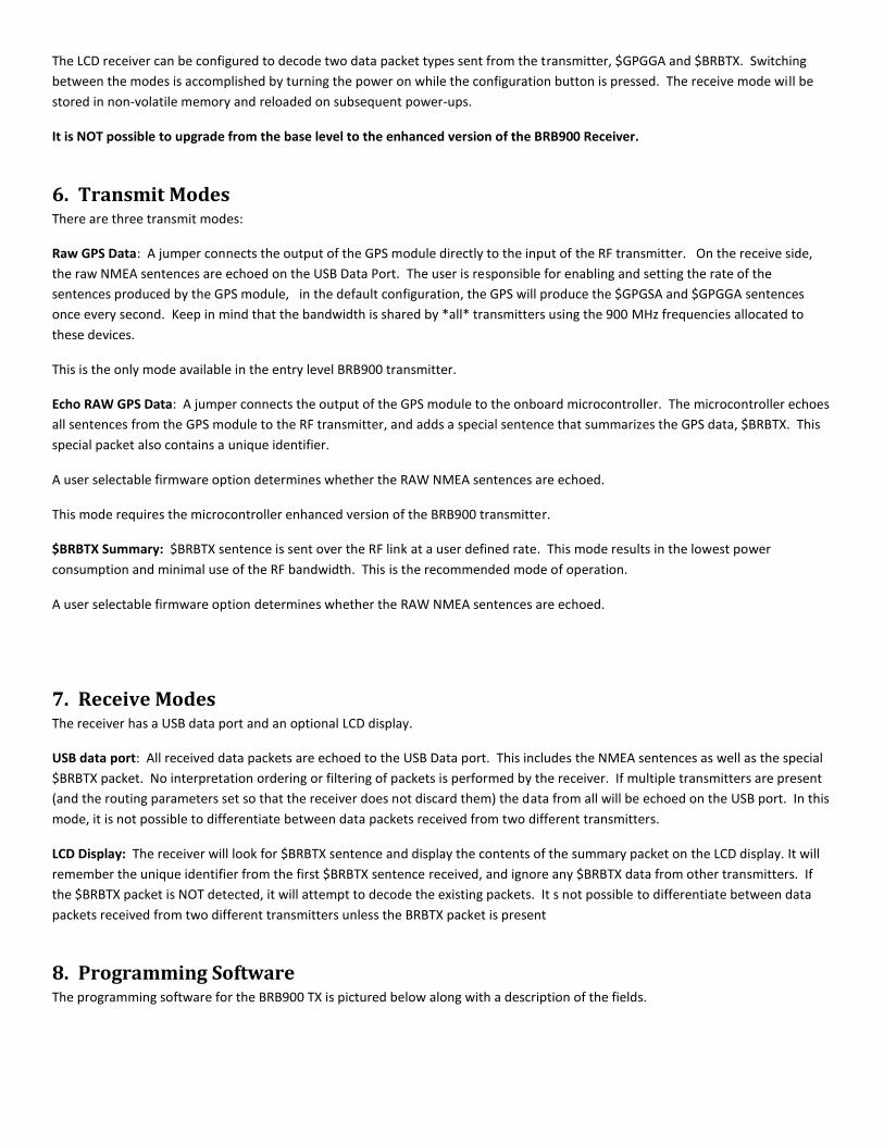
The LCD receiver can be configured to decode two data packet types sent from the transmitter, $GPGGA and $BRBTX. Switching
between the modes is accomplished by turning the power on while the configuration button is pressed. The receive mode will be
stored in non-volatile memory and reloaded on subsequent power-ups.
It is NOT possible to upgrade from the base level to the enhanced version of the BRB900 Receiver.
6. Transmit Modes There are three transmit modes:
Raw GPS Data: A jumper connects the output of the GPS module directly to the input of the RF transmitter. On the receive side,
the raw NMEA sentences are echoed on the USB Data Port. The user is responsible for enabling and setting the rate of the
sentences produced by the GPS module, in the default configuration, the GPS will produce the $GPGSA and $GPGGA sentences
once every second. Keep in mind that the bandwidth is shared by *all* transmitters using the 900 MHz frequencies allocated to
these devices.
This is the only mode available in the entry level BRB900 transmitter.
Echo RAW GPS Data: A jumper connects the output of the GPS module to the onboard microcontroller. The microcontroller echoes
all sentences from the GPS module to the RF transmitter, and adds a special sentence that summarizes the GPS data, $BRBTX. This
special packet also contains a unique identifier.
A user selectable firmware option determines whether the RAW NMEA sentences are echoed.
This mode requires the microcontroller enhanced version of the BRB900 transmitter.
$BRBTX Summary: $BRBTX sentence is sent over the RF link at a user defined rate. This mode results in the lowest power
consumption and minimal use of the RF bandwidth. This is the recommended mode of operation.
A user selectable firmware option determines whether the RAW NMEA sentences are echoed.
7. Receive Modes The receiver has a USB data port and an optional LCD display.
USB data port: All received data packets are echoed to the USB Data port. This includes the NMEA sentences as well as the special
$BRBTX packet. No interpretation ordering or filtering of packets is performed by the receiver. If multiple transmitters are present
(and the routing parameters set so that the receiver does not discard them) the data from all will be echoed on the USB port. In this
mode, it is not possible to differentiate between data packets received from two different transmitters.
LCD Display: The receiver will look for $BRBTX sentence and display the contents of the summary packet on the LCD display. It will
remember the unique identifier from the first $BRBTX sentence received, and ignore any $BRBTX data from other transmitters. If
the $BRBTX packet is NOT detected, it will attempt to decode the existing packets. It s not possible to differentiate between data
packets received from two different transmitters unless the BRBTX packet is present
8. Programming Software The programming software for the BRB900 TX is pictured below along with a description of the fields.
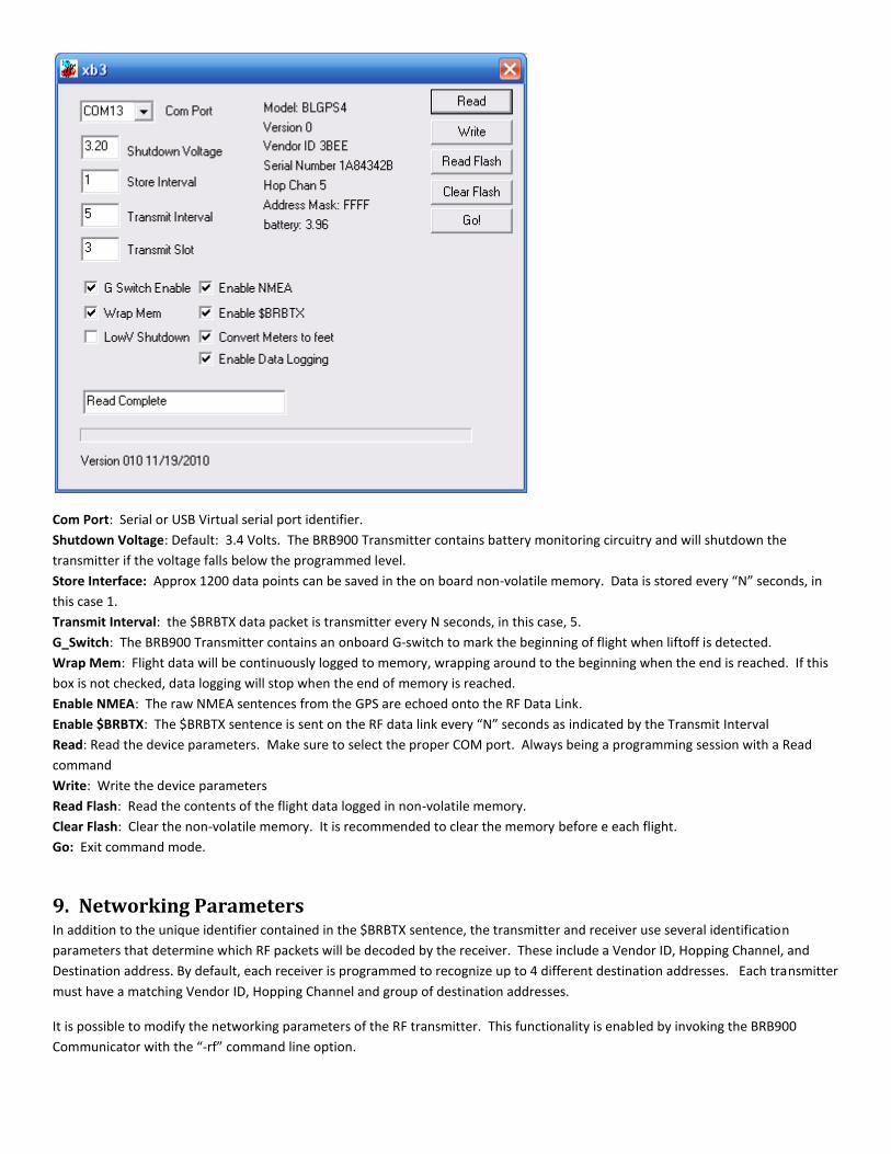
Com Port: Serial or USB Virtual serial port identifier.
Shutdown Voltage: Default: 3.4 Volts. The BRB900 Transmitter contains battery monitoring circuitry and will shutdown the
transmitter if the voltage falls below the programmed level.
Store Interface: Approx 1200 data points can be saved in the on board non-volatile memory. Data is stored every “N” seconds, in
this case 1.
Transmit Interval: the $BRBTX data packet is transmitter every N seconds, in this case, 5.
G_Switch: The BRB900 Transmitter contains an onboard G-switch to mark the beginning of flight when liftoff is detected.
Wrap Mem: Flight data will be continuously logged to memory, wrapping around to the beginning when the end is reached. If this
box is not checked, data logging will stop when the end of memory is reached.
Enable NMEA: The raw NMEA sentences from the GPS are echoed onto the RF Data Link.
Enable $BRBTX: The $BRBTX sentence is sent on the RF data link every “N” seconds as indicated by the Transmit Interval
Read: Read the device parameters. Make sure to select the proper COM port. Always being a programming session with a Read
command
Write: Write the device parameters
Read Flash: Read the contents of the flight data logged in non-volatile memory.
Clear Flash: Clear the non-volatile memory. It is recommended to clear the memory before e each flight.
Go: Exit command mode.
9. Networking Parameters In addition to the unique identifier contained in the $BRBTX sentence, the transmitter and receiver use several identification
parameters that determine which RF packets will be decoded by the receiver. These include a Vendor ID, Hopping Channel, and
Destination address. By default, each receiver is programmed to recognize up to 4 different destination addresses. Each transmitter
must have a matching Vendor ID, Hopping Channel and group of destination addresses.
It is possible to modify the networking parameters of the RF transmitter. This functionality is enabled by invoking the BRB900
Communicator with the “-rf” command line option.

These parameters can be modified so that all packets matching the Vendor ID and Hopping Channel are displayed. Additionally the
Vendor ID and Hopping Channel can be modified to match other vendors.
Default Settings for Address Parameters:
Hopping Channel (ATHP): The default hopping channel for the BRB900 transmitter and receiver is 5, and should not be changed.
Address Mask (ATMK): The default address mask is 0xFFFF and should not be changed.
Destination Address (ATDT): Each transmit/receive pair is shipped with a unique/matching destination address. In order for the
Receiver to decode the transmitter packets, the Destination addresses must match. If you purchase additional transmitters, you can
change the Destination Address to match your existing receiver.
Vendor Identification (ATID): The default Vendor ID is 0x3BEE, and should not be changed.
UPDATE: The update button will modify the BRB900 Transmitter parameters. Use extreme caution when modifying these
parameters.

GPS Parameters RF Parameters
Base Transmitter Trimble Software N/A *
Enhanced Transmitter Trimble Software BRB900 Communicator
Base Receiver X-CTU Software
Enhanced (LCD) Receiver X-CTU Software
*The RF parameters cannot be modified while the transmitters is installed in the base level transmitter
10. Special Sentence Format $BRBTX
BigRedBee Summary Information
$BRBTX, ID0001,*,033618,3412.3456N,12345.6789W,04,2.69,012345,1.24,2F0
Where:
$BRBTX BigRedBee Summary Packet ID0001 Unique identifier string * BRB Status Flag 033618 fix taken at 033618 UTC Time 3412.3456N Latitude 34 degrees 12.3456 minutes North 12345.6789W Longitude 123 degrees 45.6789W minutes West 04 4 satellites user to compute position 2.69 HDOP 012345 Altitude in Meters or Feet 1.24 VDOP 2F0 Raw A/D conversion of onboard battery voltage

11. LCD Display When the power switch is turned on, the LCD will display the following information: The firmware version (V0.01) and the battery
voltage of the receiver are displayed. The BRB-LCD can be configure to display the information from the $GPGGA sentence, or the
$BRBTX sentence. Switching between modes is accomplished by holding the configuration button while the unit is powered on.
X x x x x x x x x x x x x x x x x x
x B R B 9 0 0 V 0 . 0 1 x
x v B A T = 4 . 1 7 B R B x
x B i g R e d B e e , L L C x
x x x x x x x x x x x x x x x x x x
If the configuration button is held when power is applied, the NMEA mode will be toggled.
X x x x x x x x x x x x x x x x x x
x B R B 9 0 0 V 0 . 0 1 x
x v B A T = 4 . 1 7 N M E A x
x B i g R e d B e e , L L C x
x x x x x x x x x x x x x x x x x x
The 16x3 line LCD display contains the following information when decoding the $GPGGA NMEA sentence
X x x x x x x x x x x x x x x x x x
x * 4 5 3 4 . 5 6 7 8 H 2 6 9 x
x 1 2 2 3 4 . 5 6 7 8 x
x 1 2 3 4 5 2 3 S 4 x
x x x x x x x x x x x x x x x x x x
The 16x3 line LCD display contains the following information when decoding the $BRBTX Summary sentence before the GPS has
locked. Note that the battery voltage and # of satellites are valid.
X x x x x x x x x x x x x x x x x x
x - , , , , , , , , , , , , , x
x , , , , , , , , , , , , , , x
x , , , , , , , S 0 B 3 9 5 x
x x x x x x x x x x x x x x x x x x

The 16x3 line LCD display contains the following information when decoding the $BRBTX Summary sentence.
X x x x x x x x x x x x x x x x x x
x * 4 5 3 4 . 5 6 7 8 H 2 6 9 x
x 1 2 2 3 4 . 5 6 7 8 V 9 0 9 x
x 1 2 3 4 5 2 3 S 4 B 3 9 5 x
x x x x x x x x x x x x x x x x x x
Altitude in this mode is “MSL”. If the configuration button is held, the LCD receiver will “lock in” the currently altitude as the “base”
altitude, and report all future altitudes as “AGL”. Negative altitudes will be displayed as “0”.
*: Status Character: ‘*’
4535.567 Latitude: 45° 34.5678”
12234.5678 Longitude: 122° 34.5678”
12345 Altitude: 12345
H269 Horizontal Dilution of Precision (HDOP): 2.69
V909 Vertical Dilution of Precision (VDOP) 9.09
23 Time of Day (Seconds only): 23
S4 Number of satellites in view: 4
B395 Voltage of Battery on Transmitter 3.95V
12. BigRedBee USB Interface and Charger The BigRedBee USB interface integrates the functionality of two separate devices; a USB data
interface, and a single cell lithium poly battery charger. The charger and programming
interface functions should not be used at the same time. When programming the device, the
battery must be used to provide power. Power is NOT provided via the USB interface. Do not
attempt to charge the battery and modify the device parameters at the same time.
12.1 Single Cell Lithium Poly Charger
Plug the USB cable into the USB interface board and connect to your computer’s USB port. Plug the battery into the three pin
connector. The LED will remain on while the battery is charging, and turn off once it is fully charged. Charge rate is 100 milliamps
per hour.
The battery charger function is independent of the data interface. The battery WILL NOT CHARGE unless it is connected directly to
the 3-pin header on the USB / charger interface.
12.2 USB Data Interface
X x x x x x x x x x x x x x x x x x
x * 4 5 3 4 . 5 6 7 8 H 2 6 9 x
x 1 2 2 3 4 . 5 6 7 8 V 9 0 9 x
x 0 0 0 0 0 a 2 3 S 4 B 3 9 5 x
x x x x x x x x x x x x x x x x x x

Apply power to the transmitter. Plug the USB cable into the USB interface board and connect to your computer’s USB port.. If this is
the first time you have used this type of USB interface, Windows will need to install the drivers for it.
Once Windows has recognized the device, plug the 5-pin connector on the USB adapter into the Beeline transmitter. Now you can
use the BeeLine Communicator to modify the device parameters. Make sure to select the proper COM port
Drivers are located here: http://www.ftdichip.com/FTDrivers.htm
13. Trimble Studio:
The default configuration should work for most users, but here’s a summary of the steps needed to modify the parameters of the
GPS Module. Be careful not to touch the PORT configurations, as it can easily get you into a position where you’re unable to
communicate with the device. You should only have to make these modifications once, as they parameters are stored in non-
volatile memory inside the GPS module.
Executing Trimble studio brings up the start screen that looks like this:
Clicking on “New connection” will bring up the Port settings.
In this case, we’ve selected COM 3, and 9600-8-E-1. Click on OK

Next we see the main status screen – notice the “satellite data” section is populated with data, and that the RX light is blinking
Selecting Receiver->Configure and then select the NMEA configuration tab.

If you are using the base level transmitter, enable the sentences you desire and the Output Interval. If you are using the LCD
enhanced receiver, you should make that at at least the GGA sentence is enabled. If using the Summary mode on an enhanced
transmitter, then set the output Interval to 1, and make sure that GSA is enabled along with GGA. Make sure to “Set” and “Save
Configuration”.
The GPS configuration should be left unchanged
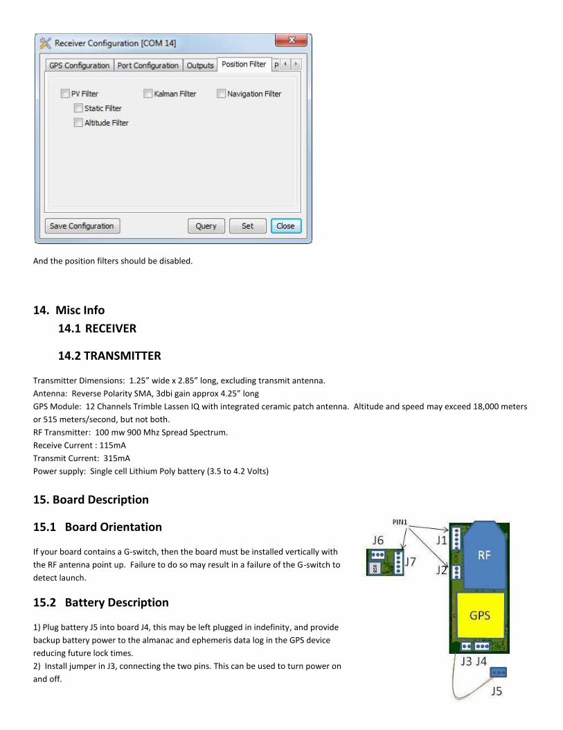
And the position filters should be disabled.
14. Misc Info
14.1 RECEIVER
14.2 TRANSMITTER
Transmitter Dimensions: 1.25” wide x 2.85” long, excluding transmit antenna.
Antenna: Reverse Polarity SMA, 3dbi gain approx 4.25” long
GPS Module: 12 Channels Trimble Lassen IQ with integrated ceramic patch antenna. Altitude and speed may exceed 18,000 meters
or 515 meters/second, but not both.
RF Transmitter: 100 mw 900 Mhz Spread Spectrum.
Receive Current : 115mA
Transmit Current: 315mA
Power supply: Single cell Lithium Poly battery (3.5 to 4.2 Volts)
15. Board Description
15.1 Board Orientation
If your board contains a G-switch, then the board must be installed vertically with
the RF antenna point up. Failure to do so may result in a failure of the G-switch to
detect launch.
15.2 Battery Description
1) Plug battery J5 into board J4, this may be left plugged in indefinity, and provide
backup battery power to the almanac and ephemeris data log in the GPS device
reducing future lock times.
2) Install jumper in J3, connecting the two pins. This can be used to turn power on
and off.

Programming:
Plug J7 into J1, aligning pin 1
15.3 GPS Programming
Plug J7 into J2, aligning pin 1.
15.4 Battery Charging
Pl lug J5 into J6, and the usb connector into the PC. The connectors are keyed, and can only be installed in one direction.