börger rotary lobe pump classic - doc.borger.frdoc.borger.fr/notice pl - anglais.pdf · america...
TRANSCRIPT

www.boerger.de www.boerger.com
Operating Manual Börger Rotary Lobe Pump
Classic PL Series
Börger Worldwide
2 www.boerger.de / www.boerger.com BA-Classic PL, 12.12.2013
Börger Worldwide Europe Germany
– Head Office –
Börger GmbH Benningsweg 24 46325 Borken-Weseke Germany
Phone +49 (0) 2862 / 91030 Fax +49 (0) 2862 / 910346 [email protected] www.boerger.de
France Börger France S.A.R.L. 9 rue des Prés 67670 Wittersheim France
Phone +33 (0) 3 / 88515468 Fax +33 (0) 3 / 88515413 [email protected] www.borger.fr
Great Britain/ Ireland
Börger UK Ltd. East Wing - Old School Watling St. Gailey Staffordshire ST19 5PR, United Kingdom
Phone +44 (0) 1902 / 798977 Fax +44 (0) 1902 / 798979 [email protected] www.boerger.com
Netherlands Belgium Luxembourg
Börger Benelux Postbus 78 7630 AB Ootmarsum Netherlands
Phone +31 (0) 541 / 293687 Fax +31 (0) 541 / 293578 [email protected] www.boerger-pumps.nl
Poland Boerger Polska Sp.z o.o. ul. Toszecka 101 44-100 Gliwice Poland
Phone +48 32 / 3356094 Fax +48 32 / 3356095 [email protected] www.boerger.pl
America USA Boerger, LLC 2860 Water Tower Place Chanhassen, MN 55317 USA
Phone +1 877 / 7263743 +1 612 / 4357300 Fax +1 612 / 4357301 [email protected] www.boerger.com
Asia and Australia / Oceania
Singapore Boerger Pumps Asia Pte. Ltd. 16 Boon Lay Way #01-48 TradeHub21 Singapore 609965
Phone +65 / 65629540 Fax +65 / 65629542 [email protected] www.boerger.com
China Boerger China Shanghai Representation Office Room 2111, No. 58 Yinqiao Building Jin Xin Road, Pudong Shanghai 201206, China
Phone +86 (0) 21 / 51389081 Fax +86 (0) 21 / 51389082 [email protected] www.boerger.com.cn
India Boerger Pumps Asia Pte. Ltd. India Representation Office German Centre, Office #21 14th floor, Building no. 9, Tower B DLF Cyber City Phase III Gurgaon 122002 Haryana, India
Phone +91 (0) 124 / 4636060 Fax +91 (0) 124 / 4636063 [email protected] www.boerger.com
Africa * Head Office Börger GmbH Benningsweg 24 46325 Borken-Weseke Germany
Phone +49 (0) 2862 / 91030 Fax +49 (0) 2862 / 910346 [email protected] www.boerger.de
Your sales partner:
– Stamp –
* Algeria, Morocco: See France, Börger France S.A.R.L.

Product Specifications
BA-Classic PL, 12.12.2013 www.boerger.de / www.boerger.com 3
Product Specifications Machine:
Product group: Classic rotary lobe pump Type: PL 100, PL 200, PL 300, PL 400,
Series no. 5
The precise product specifications for your rotary lobe pump can be found in the data sheet enclosed with this operating manual.
Manufacturer’s address:
Company: Börger GmbH Address: Benningsweg 24
Town / city: 46325 Borken – Weseke, Germany Phone: +49 (0)2862 / 9103 – 0
Fax: +49 (0)2862 / 9103 – 46 E-mail: [email protected]
Internet: www.boerger.de
Spare parts orders and customer service in Germany:
Börger GmbH
Tel. / fax: Spare parts orders – industrial sector: Tel. +49 (0)2862 / 9103 – 38 Fax +49 (0)2862 / 9103 – 49
Customer service – industrial sector:
Tel. +49 (0)2862 / 9103 – 35 Fax +49 (0)2862 / 9103 – 49
Spare parts orders and customer service – agricultural sector: Tel. +49 (0)2862 / 9103 – 31 Fax +49 (0)2862 / 9103 – 47
E-mail: [email protected]
Spare parts orders and customer service in other countries:
See contact data for your regional sales
partner
Document data: Document: BA-Classic PL_Englisch.docx Language: English translation of the German original,
available at [email protected] Issue date: 12/12/2013 (translation: 1/28/2014)

Contents
4 www.boerger.de / www.boerger.com BA-Classic PL, 12.12.2013
Contents
Börger Worldwide.......................................................................................................................... 2
Product Specifications .................................................................................................................. 3
Contents ........................................................................................................................................ 4
1 General Information ...................................................................................................... 7
1.1 Introduction ...................................................................................................................... 7 1.2 Notes on copyrights and property rights .......................................................................... 7 1.3 Information for the operator ............................................................................................. 7 1.4 Training and instruction ................................................................................................... 8 1.5 Sample training topics ................................................................................................... 10
2 Safety ........................................................................................................................... 12
2.1 General information ....................................................................................................... 12 2.2 Notes on signs and symbols .......................................................................................... 12 2.3 Proper use ..................................................................................................................... 14 2.4 Residual risk .................................................................................................................. 14 2.5 Description of the safety equipment ............................................................................... 15 2.5.1 Coupling guard .............................................................................................................. 16 2.5.2 Intermediate chamber .................................................................................................... 16 2.5.3 Optional monitoring devices .......................................................................................... 16 2.6 Markings and signs on the rotary lobe pump ................................................................. 17 2.7 Markings and signs to be attached by the operator ........................................................ 18 2.8 Safety instructions for operating personnel .................................................................... 18 2.9 Safety instructions for maintenance and rectifying malfunctions on the rotary
lobe pump...................................................................................................................... 19 2.10 Information on special dangers ...................................................................................... 20 2.10.1 Oil, grease and other chemical substances ................................................................... 20 2.10.2 Noise ............................................................................................................................. 20
3 Product Description .................................................................................................... 21
3.1 Construction of the rotary lobe pump ............................................................................. 21 3.1.1 Quick-release cover ....................................................................................................... 22 3.1.2 Pump casing .................................................................................................................. 22 3.1.3 Rotors ............................................................................................................................ 23 3.1.4 Timing gear ................................................................................................................... 24 3.1.5 Shaft seal on pump chamber ......................................................................................... 24 3.1.6 Intermediate chamber (quench) ..................................................................................... 25 3.1.7 Designs / mounting positions ......................................................................................... 27 3.1.8 Pipe connections on inlet and outlet: ............................................................................. 29 3.1.9 Pump units .................................................................................................................... 31

Contents
BA-Classic PL, 12.12.2013 www.boerger.de / www.boerger.com 5
3.1.10 Options and accessories ............................................................................................... 32 3.2 Operating principle of a rotary lobe pump ...................................................................... 32 3.3 Technical data ............................................................................................................... 33 3.3.1 Dimensions ................................................................................................................... 34 3.3.2 Performance data and maximum loads ......................................................................... 36
4 Transportation, Storage and Installation ................................................................... 39
4.1 As-delivered condition ................................................................................................... 40 4.2 Storage / interim storage ............................................................................................... 40 4.2.1 Storage .......................................................................................................................... 40 4.2.2 Interim storage .............................................................................................................. 41 4.3 Installation ..................................................................................................................... 42 4.3.1 Positioning ..................................................................................................................... 44 4.3.2 Installing the inlet and outlet .......................................................................................... 46 4.3.3 Aligning the unit ............................................................................................................. 47 4.3.4 Electrical, hydraulic and PTO shaft connection .............................................................. 49 4.3.5 Checking the pump functions ........................................................................................ 51 4.3.6 Preparation for commissioning ...................................................................................... 53
5 Operation ..................................................................................................................... 56
5.1 Qualifications for operating personnel ........................................................................... 57 5.2 Commissioning .............................................................................................................. 58 5.2.1 Test run with pumped medium ...................................................................................... 58 5.2.2 Complete commissioning............................................................................................... 59 5.3 Normal operation ........................................................................................................... 59 5.4 Downtimes .................................................................................................................... 60 5.5 Malfunctions .................................................................................................................. 61
6 Maintenance and Repairs ........................................................................................... 67
6.1 Machine care ................................................................................................................. 67 6.2 Maintenance and inspection .......................................................................................... 69 6.2.1 Maintenance and inspection plan .................................................................................. 69 6.2.2 Lubricant fill level and changing the lubricants ............................................................... 70 6.3 Repairs .......................................................................................................................... 72 6.3.1 Notes on repair work ..................................................................................................... 72 6.3.2 Opening and closing the quick-release cover ................................................................ 75 6.3.3 Replacing the rotors ...................................................................................................... 77 6.3.4 Replacing the mechanical seals .................................................................................... 86 6.3.5 Replacing the casing liners (optional) ............................................................................ 93 6.3.6 Replacing the gear-side casing protection plate ............................................................ 96 6.3.7 Other repairs ................................................................................................................. 97 6.3.8 Queries .......................................................................................................................... 97 6.3.9 Maintenance instructions for special equipment ............................................................ 97

Contents
6 www.boerger.de / www.boerger.com BA-Classic PL, 12.12.2013
7 Disposal ....................................................................................................................... 98
7.1 Environmental protection ............................................................................................... 98 7.2 Oil, oily waste and grease .............................................................................................. 98 7.3 Plastics .......................................................................................................................... 98 7.4 Metals ............................................................................................................................ 99 7.5 Electrical and electronic waste ....................................................................................... 99 7.6 Final decommissioning .................................................................................................. 99
8 Accessories ............................................................................................................... 100
8.1 Frequency converter .................................................................................................... 100 8.2 Monitoring equipment .................................................................................................. 100 8.2.1 Dry run protection with temperature sensor / conductivity sensor ................................ 100 8.2.2 Pressure monitoring devices as overpressure protection ............................................. 101 8.2.3 Pressure relief valve with bypass ................................................................................. 101 8.2.4 Level monitor with float switch ..................................................................................... 102 8.3 Auger feed ................................................................................................................... 102
9 Appendix .................................................................................................................... 103
9.1 Data sheet ................................................................................................................... 103 9.2 Wear parts ................................................................................................................... 103 9.3 Assembly drawing ....................................................................................................... 105 9.4 Complete spare parts list ............................................................................................. 108 9.5 Type code table ........................................................................................................... 120 9.6 Parallel keys ................................................................................................................ 126 9.7 Checklist for commissioning ........................................................................................ 127 9.8 EC Declaration of Conformity / EC Declaration of Incorporation .................................. 128 9.9 Additional documentation ............................................................................................ 130 9.10 Supplier documentation ............................................................................................... 130

General Information
BA-Classic PL, 12.12.2013 www.boerger.de / www.boerger.com 7
General Information 1
Introduction 1.1This operating manual is an important aid for the correct and safe operation of the rotary lobe pump.
It contains important information for operating the rotary lobe pump in a safe, proper and economical manner.
Adhering to these instructions will help avoid associated dangers, reduce repair costs and downtimes and increase the reliability and service life of the rotary lobe pump.
The operating manual must be made available at all times. All personnel who work on or with the rotary lobe pump must read and adhere to the manual. This work includes:
— Operation and troubleshooting — Maintenance (machine care, maintenance and repairs) — Transportation
Notes on copyrights and property rights 1.2This operating manual must be treated as confidential. It may only be made accessible to authorized persons. The manual may only be passed on to third parties following written approval from Börger GmbH.
All documents are protected according to the copyright laws. The distribution and reproduction of documents, in whole or in part, plus the exploitation and distribution of all associated content is forbidden unless expressly authorized in writing.
Violations will be prosecuted and may lead to claims for compensation. All rights for exercising industrial property rights are reserved by Börger GmbH.
Information for the operator 1.3The operating manual is an integral part of the rotary lobe pump. The operator (i.e. the responsible party) is responsible for making the operating personnel aware of this manual.
General Information
8 www.boerger.de / www.boerger.com BA-Classic PL, 12.12.2013
Additionally, the operator is obligated to ensure the notice and observance of national regulations for accident prevention and environmental protection, plus the notice and observance of supervision and reporting duties taking special operational aspects into account, e.g. regarding work organization, work processes and personnel.
Aside from the operating manual and the currently valid accident prevention regulations in the country of operation and at the installation site, all recognized special regulations for safe and proper operation must be observed.
The operator is not permitted to make or advise any changes, modifications or alterations to the rotary lobe pump without approval from Börger GmbH.
Any spare parts used must comply with the technical requirements specified by Börger GmbH. This is always guaranteed when original spare parts are used. Only original spare parts may be used during the warranty period, failing which the warranty is void.
Only trained or instructed personnel may be assigned to operate, maintain, repair or transport the rotary lobe pump. Clearly define the personnel responsible for operation, maintenance, repair and transportation.
Training and instruction 1.4As the operator, you are obligated to inform and, if necessary, instruct operating personnel in regard to the applicable legal and accident prevention regulations, as well as the available safety equipment on the rotary lobe pump. This obligation also applies to all other safety equipment on and around the rotary lobe pump. The different technical qualifications of the operating personnel must be taken into account.
The operating personnel must have fully understood the instructions, and adherence to the instructions must be guaranteed. Only then can your personnel work safely and be fully aware of associated risks.
Adherence to instructions must be checked on a regular basis. As the operator, you should therefore have each instructed staff member confirm their training participation in writing.
General Information
BA-Classic PL, 12.12.2013 www.boerger.de / www.boerger.com 9
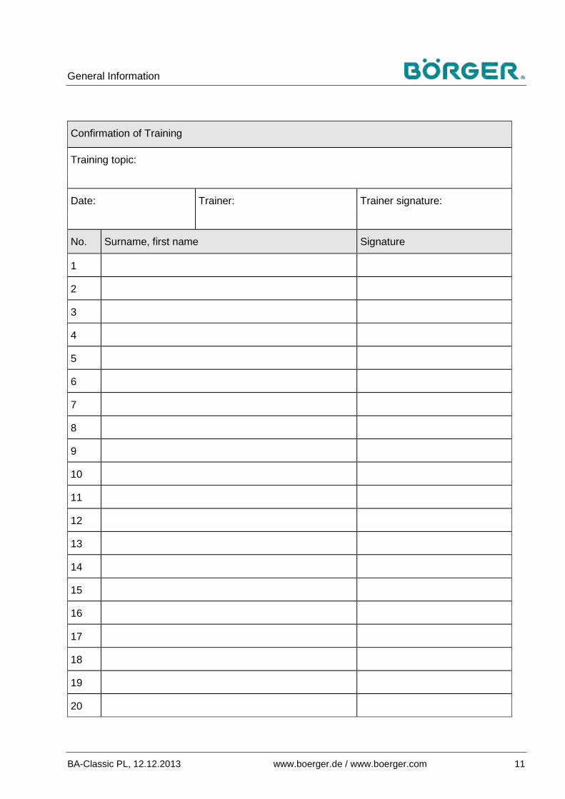
Sample training topics and a sample form for confirming participation in the training / instruction can be found on the following pages.
Börger GmbH, their regional subsidiaries or your local sales partner will be happy to help you regarding staff instruction.They can also carry out training on the functionality, commissioning, maintenance and repair of the rotary lobe pump on request.
Contact us for a detailed quotation.

General Information
10 www.boerger.de / www.boerger.com BA-Classic PL, 12.12.2013
Sample training topics 1.5
1. Operational safety
Accident prevention regulations
General legal regulations
General safety instructions
Measures in the event of emergencies
Safety instructions for operating the rotary lobe pump
Using the safety equipment on the rotary lobe pump
Safety equipment on and around the rotary lobe pump
Explanation of symbols and signs
_________________________________
_________________________________
2. Operating the rotary lobe pump
Using the operating elements on the rotary lobe pump
Explanation of the operating manual for operating personnel
Specific experiences in using the rotary lobe pump
Troubleshooting / dealing with malfunctions
_________________________________
_________________________________
3. Repair and maintenance regulations
Correct handling of cleaning agents and lubricants
Specific experiences regarding repair, maintenance, cleaning and care of the rotary lobe pump
_________________________________
_________________________________
General Information
BA-Classic PL, 12.12.2013 www.boerger.de / www.boerger.com 11
Confirmation of Training
Training topic:
Date: Trainer: Trainer signature:
No. Surname, first name Signature
1
2
3
4
5
6
7
8
9
10
11
12
13
14
15
16
17
18
19
20

Safety
12 www.boerger.de / www.boerger.com BA-Classic PL, 12.12.2013
Safety 2
General information 2.1The rotary lobe pump has been developed and constructed according to current state-of-the-art technology and recognized safety guidelines in observance of the valid safety regulations in the country of manufacture.
However, operation of the rotary lobe pump may endanger the operating person and cause damage to the pump or other material assets in the following circumstances:
— When operated by untrained or uninstructed personnel — When not used properly — When not maintained or repaired properly
Notes on signs and symbols 2.2The following terms, signs and symbols are used in this operating manual, and indicate particularly important information.
Danger!
Warns of an immediate hazardous situation with unavoidable serious injuries or death as a result if the instructions shown are not strictly adhered to.
Warning!
Warns of a hazardous situation with the possible risk of subsequent serious injuries or death if the instructions shown are not strictly adhered to.
Caution!
Warns of a possible hazardous situation with the risk of subsequent moderate or light injuries and material damage if the instructions shown are not strictly adhered to.
Safety
BA-Classic PL, 12.12.2013 www.boerger.de / www.boerger.com 13
Notice
Indicates a possible hazardous situation or unsafe, dangerous work processes that may lead to damage to the machine or surrounding area.
Note
Offers useful information on safe and proper operation.
Bullet points describe work and / or operational steps. These ●steps must be carried out from the top down.
— Indents indicate lists.
All instructions and symbols attached directly to the rotary lobe pump (e.g. warning signs, operational signs, all component designations etc.) must be strictly adhered to. They may not be removed and must be kept completely legible.
Some of the diagrams and photographic images used in this operating manual, which are only used to illustrate a function or a particular work step, show a different type of rotary lobe pump. However the functional principle or work step is the same.

Safety
14 www.boerger.de / www.boerger.com BA-Classic PL, 12.12.2013
Proper use 2.3The rotary lobe pump is a self-priming, valveless positive displacement pump.
The rotary lobe pump delivers the pumped medium specified in the data sheet continuously, at speed-proportional flow rates, in a gentle, low-pulsation procedure.
Note
The rotary lobe pump or entire unit is configured exclusively for the operating conditions entered in your request / order and specified in the order confirmation and enclosed data sheet.
Therefore, proper use of the pump is restricted to the specified pumped medium, temperatures, speeds and pump output only.
Observe the technical specifications in the data sheet.
Proper use includes compliance with the instructions on
— safety, — operation and control, — repairs and maintenance,
specified in this operating manual.
Any other use or use over and above these specifications is deemed as improper use. The operator of the rotary lobe pump is solely liable for any resulting damage.
Residual risk 2.4Even when all safety instructions are adhered to, there are residual risks involved in operating the rotary lobe pump as detailed below.
All persons that work on and with the rotary lobe pump must be aware of these residual risks and observe the associated instructions to avoid accidents or damage caused by these residual risks.

Safety
BA-Classic PL, 12.12.2013 www.boerger.de / www.boerger.com 15
It may be necessary to remove on-site safety equipment during installation and modifications. This causes a residual risk and potential danger that each operating person must be aware of:
Warning!
Risk of hand injuries when operating the rotary lobe pump!
Automatic movements of the rotary lobe pump during operation may cause hand injuries.
The operating person is obligated to check that all safety equipment is installed and fully functional before operating the rotary lobe pump.
Warning!
Risk of serious injuries caused by the pumped medium spouting out or escaping gases!
Gases or liquids may escape uncontrollably from seals and screw connections.
Especially when the quick-release cover is opened, liquid can spout out at the cover when the pump is pressurized.
Take the appropriate precautions.
Warning!
There may be a considerable danger from the drive of a complete unit, e.g. due to an electric current for an electric drive.
Please read and observe the residual risks described in the operating manual for the drive of this unit.
Description of the safety equipment 2.5The rotary lobe pump is equipped with the required safety equipment according to the applicable legal guidelines in the country of manufacture, current state-of-the-art technology and recognized safety regulations.
Safety
16 www.boerger.de / www.boerger.com BA-Classic PL, 12.12.2013
Coupling guard 2.5.1
The rotating shafts between the drive and rotary lobe pump are connected by a coupling, and must be secured by a fixed safety guard against reaching in and blockages caused by falling parts.
Börger GmbH delivers units with couplings and drives including a screw-fixed coupling guard as standard.
This coupling guard may not be removed, and must always be reinstalled carefully following removal due to maintenance.
If your rotary lobe pump is delivered without an installed drive, you must attach the enclosed coupling guard (or another suitable coupling guard) after the drive is installed.
This also applies to the V-belt / chain guards on overhead mounted drive assemblies and the coupling lantern on hydraulic units.
Intermediate chamber 2.5.2
The intermediate chamber separates the hydraulic pump part from the timing gear. It is used for monitoring the integrity of the mechanical seals on rotary lobe pumps with single-acting mechanical seals.
Overflowing caused by penetrating pumped medium indicates that the mechanical seals must be replaced immediately in order to prevent the pumped medium from entering the gear unit.
The vent hole in the intermediate chamber must not be sealed or plugged.
When the vent hole is closed tightly or has become blocked, emerging pumped medium cannot escape and will penetrate the gear unit if the mechanical seal is defective. This could damage the gear unit.
Optional monitoring devices 2.5.3
Optional monitoring devices are listed and described in chapter 8 Accessories.

Safety
BA-Classic PL, 12.12.2013 www.boerger.de / www.boerger.com 17
Markings and signs on the rotary lobe pump 2.6
Meaning: Nameplate according to DIN EN 809 1)
Location: In a clearly visible position on the rotary lobe pump 1) Different address possible, e.g. when delivered through a subsidiary. CE marking not applicable for incomplete machines where only a declaration of incorporation may be delivered, and in certain other cases.
Meaning: Protective ground connection
Location: On the base frame, to the right of the quick-release cover
Meaning: Do not touch rotating pump parts
Location: In a clearly visible position on the rotary lobe pump
Meaning: Please read the operating manuals carefully before performing any activity involving the device! Keep for future reference!
Location: In a clearly visible position on the packaging of the operating manual

Safety
18 www.boerger.de / www.boerger.com BA-Classic PL, 12.12.2013
Markings and signs to be attached by the operator 2.7The operator is obligated to label the pumped medium and the flow direction on the rotary lobe pump (see chapter 4.3.5.1).
The operator may also be required to attach additional markings and signs on or around the rotary lobe pump. These additional markings and signs may relate to regulations for wearing personal protective equipment (ear protection), for example.
Safety instructions for operating personnel 2.8The rotary lobe pump may only be operated while it is in perfect working condition and only for its intended purpose, in a safe and risk-conscious manner having regard to this operating manual. All malfunctions must be rectified immediately, especially those affecting safety.
Every person assigned with commissioning, operation or maintenance work must have fully read and understood this operating manual beforehand – specifically chapter 2, Safety. Consulting the manual during work is already too late. This applies especially to personnel that only work occasionally on the pump.
The operating manual must always be kept accessible next to the rotary lobe pump.
No liability will be assumed for any damage and accidents caused by non-compliance with the operating manual.
Adhere to the applicable accident prevention regulations and all other generally recognized safety regulations and guidelines for occupational health at work.
Clearly specify the responsible parties for the various maintenance and repair tasks and adhere thereto. Only then can handling errors be avoided, especially in dangerous situations.
The operator must make personal protective equipment mandatory for operating and maintenance personnel. This especially applies to safety shoes, protective goggles and gloves. Always wear this protective equipment when working on the rotary lobe pump.

Safety
BA-Classic PL, 12.12.2013 www.boerger.de / www.boerger.com 19
Keep long hair tied and do not wear loose clothing or jewelry. There is always a danger of getting caught, pulled in or dragged along by moving parts.
If malfunctions occur on the rotary lobe pump:
Bring the rotary lobe pump to an immediate halt. ●
Secure the pump against accidental restart. ●
Report the malfunction to the responsible department / person. ●
This especially applies to safety-related alterations to the rotary lobe pump.
Observe the maintenance instructions when carrying out maintenance on the rotary lobe pump.
Work on the rotary lobe pump may only be carried out by trained, reliable personnel. Personnel in training or requiring instruction, as well as persons currently in vocational training, may only operate the rotary lobe pump under the constant supervision of an experienced staff member.
Safety instructions for maintenance and rectifying malfunctions on 2.9the rotary lobe pump
Adhere to the prescribed intervals for regular maintenance and inspections or those specified in the operating manual.
Aside from the special tools specified in the spare parts list, suitable customary workshop equipment is essential for carrying out maintenance work.
Modifications, repairs, maintenance and troubleshooting may only be carried out when the rotary lobe pump is switched off. Accidental restarting of the unit must be prevented completely.
To the extent necessary, amply secure the surrounding area when performing maintenance. Cordon off the working area with a red and white safety chain and a warning sign.
Large assemblies and components must be carefully attached and secured to hoists when they are removed or replaced so that associated dangers are minimized. Only appropriate hoists and lifting media in technically perfect working condition with sufficient load capacities may be used.
Never stand under suspended loads.

Safety
20 www.boerger.de / www.boerger.com BA-Classic PL, 12.12.2013
At the start of maintenance, repairs or machine care, clean any dirt or cleaning agents off the connections and screw connections. Do not use any aggressive cleaning agents. Use lint-free cleaning cloths.
During installation, always tighten any screw connections that have been loosened for maintenance and repair work. Tighten to the prescribed torque, where this is specified.
Dispose of operating materials and replacement parts in a safe and environmentally-friendly manner.
Information on special dangers 2.10 Oil, grease and other chemical substances 2.10.1
When handling oil, grease and other chemical substances, pay attention and adhere to the applicable regulations and safety data sheets issued by the respective manufacturer relating to storage, handling, correct use and disposal.
Noise 2.10.2
The A-weighted equivalent continuous noise level on the workstations is below 80 dB(A) during normal operation of the rotary lobe pump. Higher noise levels may occur at the pump installation site due to local conditions. In this case, the operator is obligated to provide operating personnel with appropriate protective equipment.

Product Description
BA-Classic PL, 12.12.2013 www.boerger.de / www.boerger.com 21
Product Description 3
Construction of the rotary lobe pump 3.1
Figure 3.1-1 Rotary lobe pump components
Components: 1 Pump chamber 2 Intermediate chamber 3 Gear chamber
Figure 3.1-2 Construction of the rotary lobe pump
Construction of the rotary lobe pump (standing):
1 Quick-release cover 2 Pump casing 2.1 Connection flange, inlet (suction side)
and outlet (pressure side) 3 Rotor 4 Timing gear 4.1 Oil sight glass 4.2 Breather, oil filler for gear unit 4.3 Oil drain for gear unit 4.4 Two shafts with parallel axes; drive shaft
can optionally be at position 0 or 1 (see chapter 3.1.4)
5 Shaft seal on pump chamber 6 Intermediate chamber (quench) 6.1 Filler for quench fluid 6.2 Drain for quench fluid 6.3 Breather

Product Description
22 www.boerger.de / www.boerger.com BA-Classic PL, 12.12.2013
Quick-release cover 3.1.1
1 Quick-release cover 2 Ring nuts Figure 3.1.1 Quick-release cover
The Börger MIP principle (Maintenance in Place) starts with the quick-release cover (1):
This cover enables easy access to the interior of the pump casing and to all parts subject to wear in the pump.
The suction line and pressure line remain connected.
The cover can be removed after loosening the four ring nuts (2), see chapter 6.3.1 / 6.3.2.
The pump can be inspected, maintained and repaired directly at its point of installation.
Descriptions for other cover versions, e.g. the Variocap and the cover with groove for the temperature sensor, can be found in the supplementary operating manual in the appendix, if these versions were delivered.
Pump casing 3.1.2
Figure 3.1.2 Depths
The PL rotary lobe pump is available in four casing depths. The performance data of your rotary lobe pump depends on this depth, among other things (see chapter 3.3).
The block-type, one-piece pump casing is equipped as standard with an internal casing protection plate towards the gear unit and one towards the quick-release cover.
The pump chamber can also be completely covered with optional radial casing liners.
The pump casing is manufactured from high-quality gray cast iron, spheroidal cast iron and stainless steel.
The eighth, ninth and tenth positions of the type code indicate the relevant pump casing design and equipment.

Product Description
BA-Classic PL, 12.12.2013 www.boerger.de / www.boerger.com 23
Rotors 3.1.3
A wide variety of different rotors are available for Börger rotary lobe pumps. The rotor type on your rotary lobe pump depends on the operating conditions and the properties of the pumped medium.
The thirteenth position of the type code on the nameplate indicates the rotor design.
Type A... Dual-lobe, linear, polymers
Position 9.4 in the spare parts list
Type D... Tri-lobe, screw profile, polymers
Position 9.7 in the spare parts list
Type I...* Optimum rotor, dual-lobe, screw profile, polymers
Position 9.5 in the spare parts list
Types IS*, IE*
Optimum rotor, dual-lobe, screw profile, steel / stainless steel
Position 9.5 in the spare parts list
Type J...* Premium rotor, dual-lobe, linear, polymers
Position 9.6 in the spare parts list
Types JS, JE
Premium rotor, dual-lobe, linear, steel / stainless steel
Position 9.6 in the spare parts list
* not available for PL 400

Product Description
24 www.boerger.de / www.boerger.com BA-Classic PL, 12.12.2013
The rotor material used in your rotary lobe pump with regard to the resistance to the pumped medium is defined according to the attached data sheet and the fourteenth position of the type code.
A supplementary operating manual for special rotors with the relevant descriptions can be found in the appendix if these versions were delivered.
Timing gear 3.1.4
The rotors are driven synchronously and exactly through the carrier shafts by two gear wheels.
The shafts on the rotary lobe pump are seated on one side inside the carrier gear unit. As the gear unit is completely separate from the pump chamber, disassembly is not necessary for any maintenance work.
Depending on the ordered version, the drive shaft is installed in position 0 or position 1.
The rotary lobe pump can also be delivered with two drive shafts, e.g. a pump driven mechanically by means of the PTO shaft, where the direction of rotation can be changed by switching the PTO shaft.
The fifth position of the type code on the nameplate indicates the design and position of the drive shaft.
The timing gear is equipped with a breather system to compensate for increased pressure due to rising temperatures. The breather system must always be installed on the highest point of the pump, compare the illustrations of the pump versions for the different mounting positions in chapter 3.1.7.
Figure 3.1.4 Drive shaft position
Shaft seal on pump chamber 3.1.5
Börger rotary lobe pumps are equipped as standard with mechanical seals designed specifically for this pump type.These are used to completely seal off the pump chamber from the gear unit, or from the intermediate chamber (see chapter 3.1.6).
These seals can be quickly accessed through the pump chamber without removing the pump, and can be replaced easily.
Mechanical seals are available in a variety of material combinations.

Product Description
BA-Classic PL, 12.12.2013 www.boerger.de / www.boerger.com 25
The shaft seal of the pump chamber on your rotary lobe pump is described in the attached data sheet and is indicated by the twelfth position of the type code.
Information about any special seals that apply to your pump can be found in the additional documentation in the appendix.
Intermediate chamber (quench) 3.1.6
The pump chamber and gear chamber are separated by an intermediate chamber filled with quench fluid as standard.
The heat-absorbing quench fluid prevents the mechanical seals from running dry and captures any pumped medium that enters the intermediate chamber due to leaks in the mechanical seals. This quench function also prevents the gear unit from being damaged by intrusion of the pumped medium.
The rotor / shaft connection is also lubricated with quench fluid, thus preventing corrosion.
The intermediate chamber is sealed from the gear unit with DUO lip seals. The lip seal material is indicated by the seventh position of the type code.
To compensate an increase in pressure at rising temperatures, the intermediate chamber features a breather at the side (1, at the side on standing versions) with a vent hole.
1 Breather 2 Fill hole with screw plug Figure 3.1.6 Breather
Notice
Risk of damage to the gear unit when the vent hole is closed!
The vent hole is also used for monitoring the integrity of the mechanical seals, and must not be closed or plugged off. If the quench fluid overflows at the vent hole, this indicates a seal malfunction.
When the vent hole is closed tightly or has become blocked, emerging pumped medium cannot escape and will penetrate the gear unit if the mechanical seal is defective. This could damage the gear unit.

Product Description
26 www.boerger.de / www.boerger.com BA-Classic PL, 12.12.2013
The vent hole on the intermediate chamber can be positioned in a visible location via a pipe extension for special applications, e.g. on submerged pumps.
Optionally, the rotary lobe pump can also be supplied with a safety plug in the fill hole of the intermediate chamber. The safety plug must be able to move out without pressure when the quench is overfilled. There is no breather on the side on this version. The fill hole may only be closed with the optional safety plug.
Product Description
BA-Classic PL, 12.12.2013 www.boerger.de / www.boerger.com 27
Designs / mounting positions 3.1.7
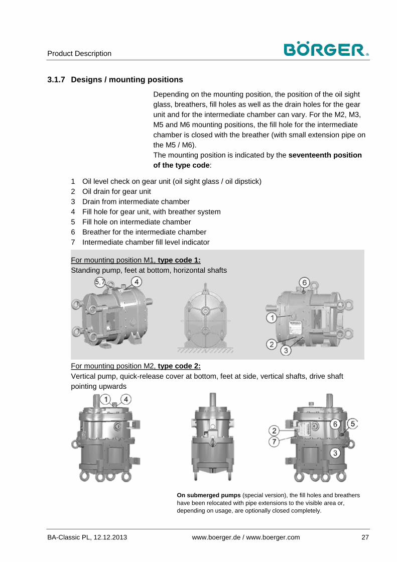
Depending on the mounting position, the position of the oil sight glass, breathers, fill holes as well as the drain holes for the gear unit and for the intermediate chamber can vary. For the M2, M3, M5 and M6 mounting positions, the fill hole for the intermediate chamber is closed with the breather (with small extension pipe on the M5 / M6). The mounting position is indicated by the seventeenth position of the type code:
1 Oil level check on gear unit (oil sight glass / oil dipstick) 2 Oil drain for gear unit 3 Drain from intermediate chamber 4 Fill hole for gear unit, with breather system 5 Fill hole on intermediate chamber 6 Breather for the intermediate chamber 7 Intermediate chamber fill level indicator
For mounting position M1, type code 1: Standing pump, feet at bottom, horizontal shafts
For mounting position M2, type code 2: Vertical pump, quick-release cover at bottom, feet at side, vertical shafts, drive shaft pointing upwards
On submerged pumps (special version), the fill holes and breathers have been relocated with pipe extensions to the visible area or, depending on usage, are optionally closed completely.

Product Description
28 www.boerger.de / www.boerger.com BA-Classic PL, 12.12.2013
1 Oil level check on gear unit (oil sight glass / oil dipstick) 2 Oil drain for gear unit 3 Drain from intermediate chamber 4 Fill hole for gear unit, with breather system 5 Fill hole on intermediate chamber 6 Breather for the intermediate chamber 7 Intermediate chamber fill level indicator
For mounting position M3, type code 3: Pump upside-down, feet upwards, horizontal shafts
For mounting position M5, type code 5: Pump turned 90° to the left, feet to the right, horizontal shafts
For mounting position M6, type code 6: Pump turned 90° to the right, feet to the left, horizontal shafts

Product Description
BA-Classic PL, 12.12.2013 www.boerger.de / www.boerger.com 29
Pipe connections on inlet and outlet: 3.1.8
In most cases, Börger rotary lobe pumps are equipped with pipe connectors on the inlet and outlet that have been specially designed for the different mounting conditions. The inlet and outlet can be equipped with the same or different pipe connectors. Pipe connectors are available with a variety of connections, for example: — DIN EN flange / DIN flange — ANSI / ASME flange — Quarter turn coupling — Quick-release coupling, e.g. Perrot, female adapter (optional
male) — Dairy screw connections, and others The pipe connectors can be equipped with optional additional fittings, e.g. screw socket G½" (½" BSPP female) or G 1" (1" BSPP female) for the connection of pressure gauges, shut-off devices or vent devices.
Pipe connectors (sample designs) – Short, straight pipe connector:
– 90° pipe bend connection towards the front, back, top or bottom:
– Gooseneck version – Angled version each with connection towards the front, back or side:

Product Description
30 www.boerger.de / www.boerger.com BA-Classic PL, 12.12.2013
– Angled version for narrow installations, connection towards the front, back, top or bottom:
– Double bend upwards, connection towards the front, back, top, bottom or side:
– Continuous, fully-pivotable suction and pressure connection, with quick-release coupling, e.g. Perrot system:
A 90° turned rotary lobe pump can be equipped with an intake hopper on the inlet for highly viscous, fluid material:

Product Description
BA-Classic PL, 12.12.2013 www.boerger.de / www.boerger.com 31
Pump units 3.1.9
The majority of Börger rotary lobe pumps are delivered as a complete unit, i.e. with mounted drive fixed on a base frame. The most common unit variations are as follows:
Standard unit 1 Börger rotary lobe pump 2 Torsionally flexible coupling 3 Coupling guard 8 Drive (with gear reducer in this example) 10 Base frame 11 Pipe connector (short, straight pipe connector with flange in
this example) 12 Motor plate
Figure 3.1.9-1 Pump unit with torsionally flexible coupling
Figure 3.1.9-2 Pump unit with V-belt or chain drive
Overhead mounted drive assembly (piggyback) 1 Börger rotary lobe pump 4 V-belt pulley / chain drive 5 V-belt (up to five belts, depending on the drive) or chain drive 6 V-belt / chain guard 8 Drive (with gear reducer in this example) 10 Base frame 11 Pipe connector (short, straight pipe connector with flange in
this example) 12 Motor plate
Figure 3.1.9-3 Pump unit with hydraulic drive
Pump unit with hydraulic drive 1 Börger rotary lobe pump 2 Torsionally flexible coupling 7 Hydraulic drive 9 Coupling lantern / drive fastening 11 Pipe connector (short, straight pipe connector with flange in
this example)

Product Description
32 www.boerger.de / www.boerger.com BA-Classic PL, 12.12.2013
Options and accessories 3.1.10
A variety of special equipment and additional accessories (cf.chapter 8) are available for the safe operation of the rotary lobe pump.
You can determine whether your rotary lobe pump has special equipment on the nameplate (19th position onwards in type code). You will find explanations referring to the special equipment and any delivered accessories in the appendix.
Notice
Risk of material damage due to non-compliance with the operating manuals for accessories!
If your rotary lobe pump is equipped with special equipment, then you must first read the corresponding supplementary operating manual for the equipment or accessories before carrying out any installation, commissioning or repair work on the pump.
Otherwise, you run the risk of damaging the rotary lobe pump.
Operating principle of a rotary lobe pump 3.2
Börger rotary lobe pumps are self-priming, valveless, positive displacement pumps.
The rotors are turned in opposite directions via an external drive using two parallel shafts.
The geometry of the rotors results in a complete separation of the suction chamber (1) and pressure chamber (3).
The synchronous rotation of the rotor pairs creates a vacuum on the priming side of the pump, which can be defined by the direction of rotation of the drive. This vacuum draws the liquid into the pump chamber.
The dynamic transfer (2) from the suction chamber to the pressure chamber allows low-pulsation pumping, and nearly pulsation-free pumping when screw rotors are used.
1 Suction chamber 2 Transfer from suction
chamber to pressure chamber
3 Pressure chamber Figure 3.2 Operating principle

Product Description
BA-Classic PL, 12.12.2013 www.boerger.de / www.boerger.com 33
The pumped medium is forced into the pressure lines on the pressure side (3) through the rotating, intermeshing rotors.
Depending on the rotor type, up to six chamber charges are displaced with each drive rotation.
The symmetrical construction of the rotary lobe pump means that the flow direction can be changed by reversing the direction of rotation, provided this is allowed by the system.
When the rotor pair is at a standstill, the pump seals off almost completely.
Technical data 3.3Börger rotary lobe pumps are configured individually for the application requirements. This leads to a wide range of variations that have been optimized for specific applications. Therefore, only some of the standard versions can be listed here as examples. Detailed specifications for your rotary lobe pump or unit can be found in the data sheet and the individual dimensional drawing sent when the pump was ordered. Please contact Börger customer service if you require a copy of this drawing.

Product Description
34 www.boerger.de / www.boerger.com BA-Classic PL, 12.12.2013
Dimensions 3.3.1
3.3.1.1 Pump without attachment parts
Dimensions of standard Classic PL rotary lobe pump in mm / inches (approx.) PL... A a1 B C c1 D E F G H i J Ø K L M N O P
100 47 1.85
90 3.54
116 4.56
15 .59
45 1.77
160 6.30
460 18.11
393 15.47
250 9.84
200 7.87
250 9.84
225 8.86
35 1.38
105 4.13
80 3.15
G½" ½" BSPP
165 6.5
G½" ½" BSPP
200 91 3.58
145 5.71
116 4.56
37.5 1.48
67.5 2.66
215 8.46
515 20.28
393 15.47
250 9.84
200 7.87
250 9.84
225 8.86
35 1.38
105 4.13
80 3.15
G½" ½" BSPP
165 6.5
G½" ½" BSPP
300 147 5.79
200 7.87
116 4.56
65 2.56
95 3.74
270 10.63
570 22.44
393 15.47
250 9.84
200 7.87
250 9.84
225 8.86
35 1.38
105 4.13
80 3.15
G½" ½" BSPP
165 6.5
G½" ½" BSPP
400 201 7.91
255 10.04
116 4.56
92.5 3.64
122.5 4.82
325 12.79
625 24.61
393 15.47
250 9.84
200 7.87
250 9.84
225 8.86
35 1.38
105 4.13
80 3.15
G½" ½" BSPP
165 6.5
G½" ½" BSPP
PL... Ø Q q1 R s t u v w x y Weight:
100 13 .51 M8x15 178
7.01 8
.31 — — 74 2.91
80 3.15
144 5.67
160 6.30
approx. 96 kg 211.2 lb
200 13 .51 M8x15 178
7.01 8
.31 32
1.25 55
2.16 — 80 3.15
144 5.67
160 6.30
approx. 107 kg 235.9 lb
300 13 .51 M8x15 178
7.01 8
.31 32
1.25 55
2.16 — 80 3.15
144 5.67
160 6.30
approx. 116 kg 255.7 lb
400 13 .51 M8x15 178
7.01 8
.31 32
1.25 55
2.16 — 80 3.15
144 5.67
160 6.30
approx. 129 kg 287.4 lb

Product Description
BA-Classic PL, 12.12.2013 www.boerger.de / www.boerger.com 35
3.3.1.2 Pipe connectors
The pipe connectors are designed according to the dimensional drawing created for the order.
We deliver short, straight pipe connectors as standard, with flanges (selectable) according to:
— DIN EN 1092-1, for some pipe diameters (pump side) according to former DIN 2633, PN 10/16
— ANSI/ASME B 16.5 RF Class 150
Short, straight pipe connectors with connection flange and O-ring seal, dimensions in mm / inches (approx.) Size PL 100 PL 200 PL 300 PL 400 DIN / EN ANSI / ASME DIN / EN ANSI / ASME DIN / EN ANSI / ASME DIN / EN ANSI / ASME
Nominal diameter: A B A B A B A B A B A B A B A B
DN 50 (2") 176 6.92
602 23.70
195 7.68
640 25.20
156 6.14
562 22.13
175 6.89
600 23.62 — — — — — — — —
DN 65 (2½") 141 5.55
532 20.94
166 6.54
582 22.91
176 6.93
602 23.7
201 7.91
652 25.67
200 7.84
650 25.59
225 8.86
700 27.56 — — — —
DN 80 (3") 146 5.75
542 21.34
166 6.54
582 22.91
156 6.14
562 22.13
175 6.89
600 23.62
236 9.29
722 28.42
256 10.08
762 30.00 — — — —
DN 100 (4") 146 5.75
542 21.34
170 6.69
590 23.23
136 5.35
522 20.55
160 6.3
570 22.44
201 7.91
652 25.67
225 8.86
700 27.56
221 8.7
692 27.24
245 9.64
740 29.13
DN 125 (5") 176 6.92
602 23.70
210 8.27
670 26.38
151 5.94
552 21.73
185 7.28
620 24.41
161 6.34
572 22.52
195 7.68
640 25.2
188 7.4
626 24.65
222 8.74
694 27.32
DN 150 (6") 176 6.92
602 23.70
210 8.27
670 26.38
181 7.13
612 24.09
215 8.46
680 26.77
166 6.54
582 22.91
200 8.87
650 25.59
191 7.52
632 24.88
225 8.86
700 27.56
DN 200 (8") 236 9.29
722 28.43
276 10.87
802 31.57
251 9.88
752 29.61
291 11.46
832 32.76
196 7.71
642 25.276
236 9.29
722 28.42
221 8.7
692 27.24
261 10.28
772 30.39
When using two 2 mm (.08") gaskets, 4 mm (.16") must be added to the specified B dimensions and 2 mm (.08") to the specified A dimensions.
Deviations in individual dimensions within an acceptable tolerance due to production cannot be ruled out.
3.3.1.3 Base frame (standard version)
Base frame for PL 100 to 300, dimensions (mm / inches)
A B C D E F G P1 P2 P3 890
35.04 90
3.54 420
16.54 810
31.89 40
1.57 30
1.18 17.5 .69
160 6.30
215 8.46
270 10.63
Weight: approx. 40 kg (88.18 lb)
Product Description
36 www.boerger.de / www.boerger.com BA-Classic PL, 12.12.2013
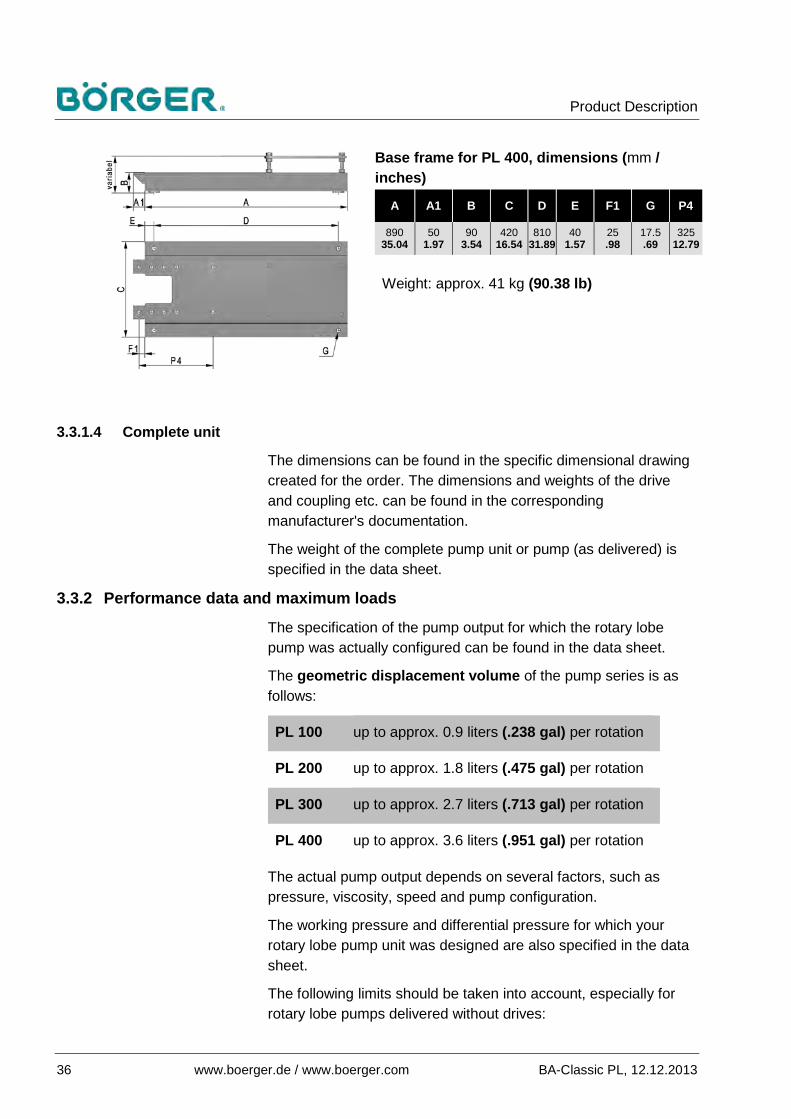
Base frame for PL 400, dimensions (mm / inches)
A A1 B C D E F1 G P4
890 35.04
50 1.97
90 3.54
420 16.54
810 31.89
40 1.57
25 .98
17.5 .69
325 12.79
Weight: approx. 41 kg (90.38 lb)
3.3.1.4 Complete unit
The dimensions can be found in the specific dimensional drawing created for the order. The dimensions and weights of the drive and coupling etc. can be found in the corresponding manufacturer's documentation.
The weight of the complete pump unit or pump (as delivered) is specified in the data sheet.
Performance data and maximum loads 3.3.2
The specification of the pump output for which the rotary lobe pump was actually configured can be found in the data sheet.
The geometric displacement volume of the pump series is as follows:
PL 100 up to approx. 0.9 liters (.238 gal) per rotation
PL 200 up to approx. 1.8 liters (.475 gal) per rotation
PL 300 up to approx. 2.7 liters (.713 gal) per rotation
PL 400 up to approx. 3.6 liters (.951 gal) per rotation
The actual pump output depends on several factors, such as pressure, viscosity, speed and pump configuration.
The working pressure and differential pressure for which your rotary lobe pump unit was designed are also specified in the data sheet.
The following limits should be taken into account, especially for rotary lobe pumps delivered without drives:
Product Description
BA-Classic PL, 12.12.2013 www.boerger.de / www.boerger.com 37
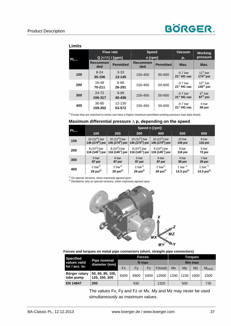
Limits
PL...
Flow rate Speed Vacuum Working pressure Q [m³/h] / [gpm] n [rpm] ps
Recommended Permitted Recommen
ded Permitted Max. Max.
100 8-24 35-106
3-33 13-145 150-450 50-600 -0.7 bar
21" HG vac 121) bar
1741) psi
200 16-48 70-211
6-66 26-291 150-450 50-600 -0.7 bar
21" HG vac 101) bar 1451) psi
300 24-72 106-317
9-99 40-436 150-450 50-600 -0.7 bar
21" HG vac 61) bar
871) psi
400 36-80 159-352
12-130 53-572 150-450 50-600 -0.7 bar
21" HG vac 4 bar 58 psi
1) Pumps that are switched in series can have a higher maximum permitted working pressure (see data sheet).
Maximum differential pressure ∆ p, depending on the speed
PL... Speed n [rpm]:
100 200 300 400 500 600
100 10 (121)) bar 145 (1741)) psi
10 (121)) bar 145 (1741)) psi
10 (121)) bar 145 (1741)) psi
10 (121)) bar 145 (1741)) psi
10 bar 145 psi
8 bar 116 psi
200 8 (101)) bar 116 (1451)) psi
8 (101)) bar 116 (1451)) psi
8 (101)) bar 116 (1451)) psi
8 (101)) bar 116 (1451)) psi
8 bar 116 psi
5 bar 72 psi
300 6 bar 87 psi
6 bar 87 psi
6 bar 87 psi
6 bar 87 psi
4 bar 58 psi
2 bar 29 psi
400 2 bar2) 29 psi2)
2 bar2) 29 psi2)
2 bar2) 29 psi2)
2 bar2) 29 psi2)
1 bar 2) 14.5 psi2)
1 bar 2) 14.5 psi2)
1) On special versions, when expressly agreed upon 2) Deviations only on special versions, when expressly agreed upon
Forces and torques on metal pipe connectors (short, straight pipe connectors)
Specified values valid for / acc. to:
Pipe nominal diameter (mm)
Forces Torques N max Nm max
Fx Fy Fz F(total) Mx My Mz M(total) Börger rotary lobe pump
50, 65, 80, 100, 125, 150, 200 6400 8900 6400 12600 1330 1150 1600 2300
EN 14847 200 930 1320 500 735
The values Fx, Fy and Fz or Mx, My and Mz may never be used simultaneously as maximum values.

Product Description
38 www.boerger.de / www.boerger.com BA-Classic PL, 12.12.2013
The specified values are calculated, and may deviate in practice due to casting tolerances and structural changes. Therefore, the limits specified in terms of EN ISO 14847 for pipe diameter 200 should not be exceeded.
Notice
Risk of material damage due to stress in the pipes!
Börger rotary lobe pumps are robust, and are constructed for use with high loads. However, the pump must not be used as an anchor point for the pipe under any circumstances.
In particular, misalignment between the pump flange and pipe must not occur, see chapter 4.3.
Even at low vibrations, the stress generated on the pipe during pump operation can lead to cracks on weaker components / weld seams.
Transportation, Storage and Installation
BA-Classic PL, 12.12.2013 www.boerger.de / www.boerger.com 39
Transportation, Storage and Installation 4
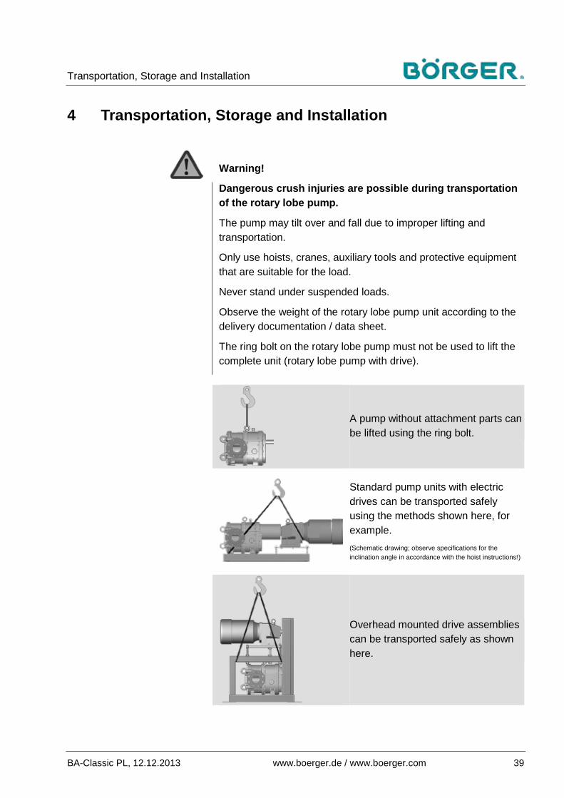
Warning!
Dangerous crush injuries are possible during transportation of the rotary lobe pump.
The pump may tilt over and fall due to improper lifting and transportation.
Only use hoists, cranes, auxiliary tools and protective equipment that are suitable for the load.
Never stand under suspended loads.
Observe the weight of the rotary lobe pump unit according to the delivery documentation / data sheet.
The ring bolt on the rotary lobe pump must not be used to lift the complete unit (rotary lobe pump with drive).
A pump without attachment parts can be lifted using the ring bolt.
Standard pump units with electric drives can be transported safely using the methods shown here, for example. (Schematic drawing; observe specifications for the inclination angle in accordance with the hoist instructions!)
Overhead mounted drive assemblies can be transported safely as shown here.

Transportation, Storage and Installation
40 www.boerger.de / www.boerger.com BA-Classic PL, 12.12.2013
If a special base frame with additional lifting lugs was ●delivered, use the lugs accordingly.
As-delivered condition 4.1The rotary lobe pump or complete rotary lobe pump unit is delivered in a pre-assembled, packed state. Optional accessories may be included in separate packaging.
Observe the applicable delivery conditions for the order. ●
Check that the delivery is complete when you receive it. ●
Inspect the delivery immediately for any signs of transport ●damage.
Ensure that the unit is not put into operation in the event of ●incorrect or incomplete delivery, or transport damage.
Inform the shipping agent immediately of any transport ●damage and contact Börger GmbH.
Storage / interim storage 4.2 Storage 4.2.1
If the rotary lobe pump is not used immediately, then appropriate storage conditions are as important as the correct installation and maintenance for subsequent trouble-free operation.
Always adhere to the following storage conditions for the ●rotary lobe pump:
– The storage room must be evenly ventilated and free of dust and vibrations.
– The relative humidity must be below 65% and the temperature between 15 °C and 25 °C (59 °F and 77 °F)
– Avoid exposure to direct heat sources (sunlight, heating).
Repair any damage to the external coating, galvanized ●components and corrosion protection on bare metal parts caused by external influences.
Protect the rotary lobe pump from cold, moisture, ●contamination and mechanical influences.
Close the inlet and outlet connections in particular (flange, coupling etc.), plus any other openings to the interior of the pump with covers impermeable to moisture.
Transportation, Storage and Installation
BA-Classic PL, 12.12.2013 www.boerger.de / www.boerger.com 41
When the pump is stored for longer periods, rotate the rotating ●parts several times after about six months (or more often, depending on the storage conditions). This way the gears, bearings and shaft seals are moved and coated again with lubricant.
Before commissioning / recommissioning at a later date, ●remove all protective covers and anti-corrosion coatings.
If the device was stored for two years or more, or if the storage conditions detailed above could not be met:
Replace the lubricants before commissioning. ●
Check the O-rings that come into contact with the medium, the ●elastomer rotors and the mechanical seals and replace them if necessary.
Note
Börger GmbH recommends contacting Börger customer service in these cases.
Observe the drive manufacturer's instructions for storing the ●drive.
Interim storage 4.2.2
For the interim storage of a used pump, the following applies:
Clean the rotary lobe pump thoroughly. ●
Apply suitable corrosion protection to the rotary lobe pump. ●
Follow the storage instructions as detailed in chapter 4.2.1. ●

Transportation, Storage and Installation
42 www.boerger.de / www.boerger.com BA-Classic PL, 12.12.2013
Installation 4.3
Note
The pipe lengths and nominal diameters must have been defined before the pump was configured.
Check that the original pipe layout has been adhered to before installing the pump. A change in pipe diameter, length etc. can completely change the suction and pressure conditions in the system.
Börger rotary lobe pumps are configured for different mounting positions. Refer to the diagram in chapter 3.1.7 for the mounting position of your rotary lobe pump. Depending on the design, it may be necessary to replace the temporary shipping plugs in the intermediate chamber and gear unit with the breather (intermediate chamber) and the breather system (gear unit).
Check all specifications in the technical data sheet and only ●install the rotary lobe pump if it is suitable for the intended application.
Apart from the performance data on the rotary lobe pump, also ●check that the materials are compatible with the pumped medium.
If available, replace the temporary shipping plug on the ●intermediate chamber with the breather and that on the gear unit with the breather system. Refer to the design diagram in chapter 3.1.7.
If your rotary lobe pump was delivered on a base frame without a drive:
Connect the rotary lobe pump to a suitable drive. Observe the ●appropriate speed and sufficient torque, and take all necessary parameters into account, such as viscosity, the solid content of the medium, pump pressure, displacement volume and desired flow rate.
Attach a suitable cover (coupling guard) for the rotating parts. ●

Transportation, Storage and Installation
BA-Classic PL, 12.12.2013 www.boerger.de / www.boerger.com 43
If your rotary lobe pump was delivered without a drive or base frame:
Attach the rotary lobe pump to a solid, rigid surface. ●
Connect the rotary lobe pump to a suitable drive, see the ●previous section.
If your rotary lobe pump was delivered without pipe connectors:
(with standard rectangular flanges on the inlet and outlet), the appropriate pipe connectors must be attached as follows:
Use the following components accordingly: ●
– Flange screws (spare parts list, position 58) – Spring washers (spare parts list, position 54) for securing
the flange screws – Seals made from materials compatible with the pumped
medium
O-ring seals (spare parts list, position 25.1) must be used as standard, and are to be installed into the O-ring groove on the pump inlet / pump outlet. Optionally, gaskets are also used (spare parts list, position 25.2), e.g. for agricultural pumps.
Gradually tighten the flange screws used to install the pipe ●connectors on the pump inlet and outlet crosswise so that the leak tightness of the connection is guaranteed. Observe the maximum torque specified below. Make sure that the seals and the spring washers are not damaged and not to squeeze out the rubber gaskets (NBR, EPDM, FKM).
Torque specifications
O-ring seals and PTFE-based gaskets
M8 steel screws 25 Nm (221 in-lbs)
M8 stainless steel screws, property class 70
20 Nm (177 in-lbs)
The torque cannot be attained when using gaskets made of NBR, EPDM or FKM. For these seals, gradually tighten the screws crosswise, however only insofar that the seals are not squeezed out.
Transportation, Storage and Installation
44 www.boerger.de / www.boerger.com BA-Classic PL, 12.12.2013
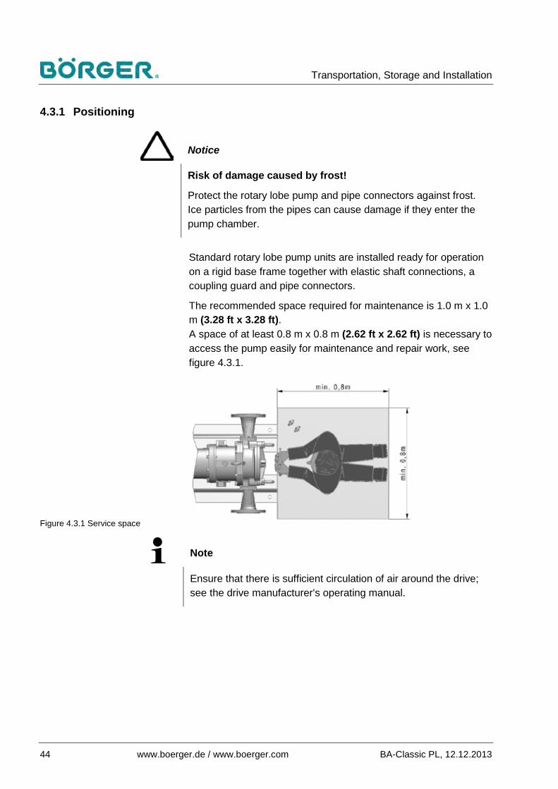
Positioning 4.3.1
Notice
Risk of damage caused by frost!
Protect the rotary lobe pump and pipe connectors against frost. Ice particles from the pipes can cause damage if they enter the pump chamber.
Standard rotary lobe pump units are installed ready for operation on a rigid base frame together with elastic shaft connections, a coupling guard and pipe connectors.
The recommended space required for maintenance is 1.0 m x 1.0 m (3.28 ft x 3.28 ft). A space of at least 0.8 m x 0.8 m (2.62 ft x 2.62 ft) is necessary to access the pump easily for maintenance and repair work, see figure 4.3.1.
Figure 4.3.1 Service space
Note
Ensure that there is sufficient circulation of air around the drive; see the drive manufacturer's operating manual.

Transportation, Storage and Installation
BA-Classic PL, 12.12.2013 www.boerger.de / www.boerger.com 45
4.3.1.1 Versions with base frames
Note
The nuts underneath the base frame must be accessible with a wrench from the front and back. If realignment is required or a pump is reinstalled on the base frame (e.g. following repairs or replacement), then it must be possible to hold the nuts in place with a wrench.
Only set the base frame in concrete if a suitable special base frame has been delivered as agreed upon in advance.
The surface must be solid, level, clean and dry.
Position the base frame without subjecting it to stress. ●
Compensate for any unevenness in the floor, e.g. by using ●washers.
Install the base frame onto the reinforced surface without ●subjecting it to stress, e.g. using four suitable M12x160 anchor bolts and appropriate resin capsules or four other safe fixing systems suitable for the surface and the application.
4.3.1.2 Other versions
Mobile pumps must be operated on a solid surface and be ●secured in place. Double-check this.
Pumps that are operated on a vehicle must be fixed to the ●vehicle frame. Double-check this.
When installing special pump versions (e.g. submerged ●pumps), check whether a supplementary operating manual is enclosed in the appendix and, if so, follow the instructions.
Transportation, Storage and Installation
46 www.boerger.de / www.boerger.com BA-Classic PL, 12.12.2013
Installing the inlet and outlet 4.3.2
Suitable seals are required for installing the inlet and outlet pipe connectors to the pipes / hoses, i.e. gaskets are required on flange connections. These must be resistant against the pumped medium.
The type, design, nominal diameter and nominal pressure of the connection flanges (or any special connections) are specified in the order confirmation / data sheet. Only suitable counter flanges / connectors may be attached in combination with the appropriate seals.
The pipes to be connected must correspond to the specifications in the order (material, DN, PN, NPSHA value etc.).
Note
Pipes to be connected and any additional components such as valves, check valves etc. must not subject the pump and flange connections to stress. All components must be supported as close to the pump as possible according to the valid general technical rules.
Note
In order to avoid cavitation, the rotary lobe pump should only have to negotiate a minimal priming height or no priming height at all. The NPSH value on the system (NPSHavail. / NPSHA) must always be sufficiently larger than the required NPSH value on the pump (NPSHreq. / NPSHR). The following applies here:
NPSHavail. > NPSHreq. + 0.5 m (1.64 ft) or NPSHA > NPSHR + 0.5 m (1.64 ft).
Depending on the application (e.g. when used with gas-emitting media) and pipe construction, it may be advisable to equip the pipe system with vents at high points. Ensure that no pockets of air can build up in front of or behind the pump.
Clean all connection flanges and all other connections before ●installation and ensure that they are not damaged.
Transportation, Storage and Installation
BA-Classic PL, 12.12.2013 www.boerger.de / www.boerger.com 47
On flange connections, ensure that the flanges are positioned ●exactly face to face, even without being fixed by screws. They must not be inclined, nor pressed together, nor spring backwards due to tensile forces.
Prevent any stress on the pipes connected to the pump by ●taking suitable measures.
Use seals that are suitable for the connections. ●
Install the connections to the matching pieces on the pipes or ●hoses without stress. When necessary, apply the appropriate torque for the connection. Consult the manufacturer's instructions for coupling connections, e.g. Perrot couplings and dairy screw connections, etc.
Aligning the unit 4.3.3
4.3.3.1 On versions with torsionally flexible couplings
In order to rule out damage caused by displacement, you must check the alignment of the coupling on pump units with gear motors mounted on a base frame after the pump is installed.
Refer to the manual from the coupling manufacturer in the ●appendix.
Note
The coupling guard is a safety-relevant component.
It prevents personnel from reaching into rotating parts.
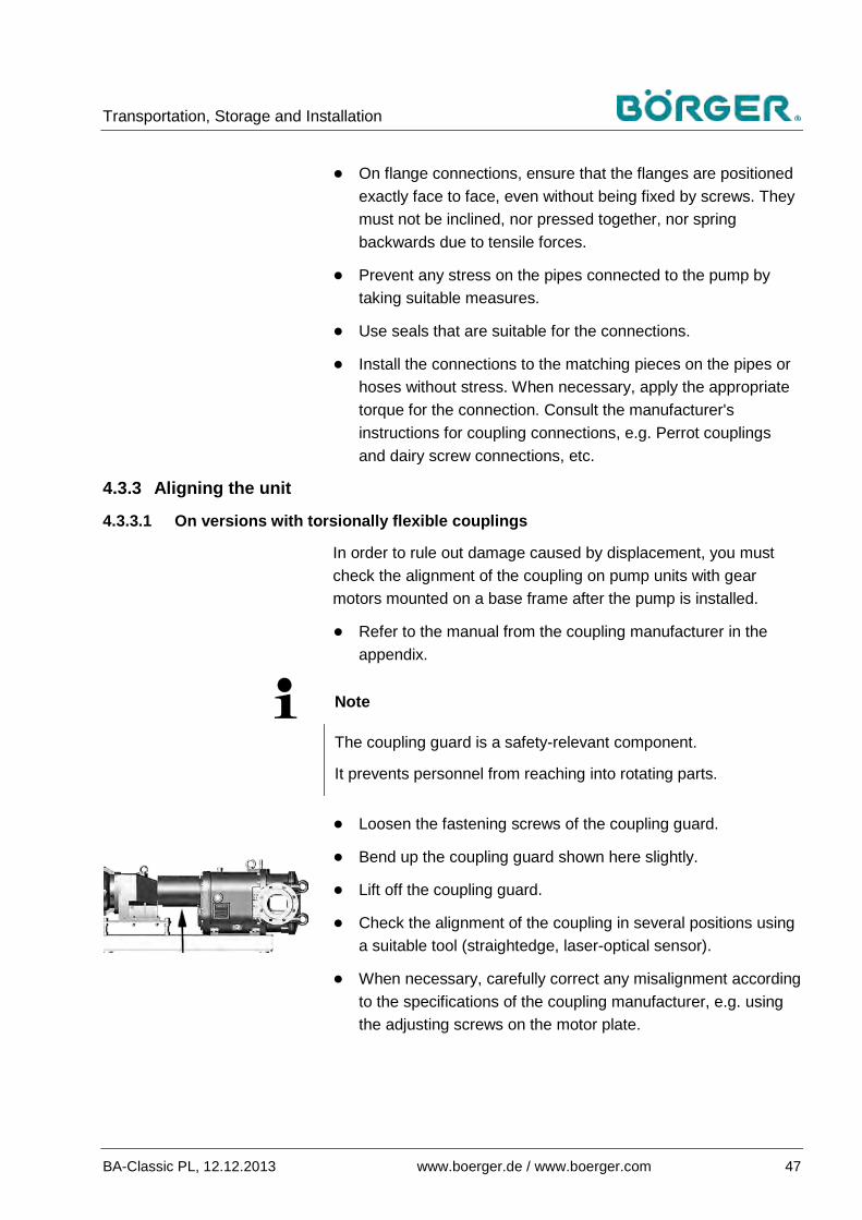
Loosen the fastening screws of the coupling guard. ●
Bend up the coupling guard shown here slightly. ●
Lift off the coupling guard. ●
Check the alignment of the coupling in several positions using ●a suitable tool (straightedge, laser-optical sensor).
When necessary, carefully correct any misalignment according ●to the specifications of the coupling manufacturer, e.g. using the adjusting screws on the motor plate.

Transportation, Storage and Installation
48 www.boerger.de / www.boerger.com BA-Classic PL, 12.12.2013
Reattach the coupling guard correctly. Fasten all fastening ●screws tightly.
Check the screws used to fasten the pump to the base frame ●and retighten them, if necessary.
4.3.3.2 On overhead mounted drive assemblies
The correct belt pre-tension or chain tension is necessary for correct belt drive or chain drive functionality and a long service life for the V-belts / chains.
Observe the specifications from the V-belt or chain ●manufacturer in the appendix.
Note
The V-belt / chain guard is a safety-relevant component.
It prevents personnel from reaching into rotating parts.
After receiving your rotary lobe pump with belt drive or chain ●drive, check that the V-belt or chain is positioned correctly and that the pre-tension is correct according to the manufacturer's specifications.
Check the screws used to fasten the pump to the base frame ●and retighten them, if necessary.
Transportation, Storage and Installation
BA-Classic PL, 12.12.2013 www.boerger.de / www.boerger.com 49
Electrical, hydraulic and PTO shaft connection 4.3.4
4.3.4.1 Electrical connection
The rotary lobe pump must be completely installed before establishing the electrical connections.
Note
A machine must be integrated in an emergency stop system.
It is only permissible to do without an emergency stop device if this omission would not reduce the stopping time and if the emergency stop device would not enable the special measures required to deal with the risk to be taken. The normal shutdown equipment must then be labeled accordingly.
Danger!
Risk of fatal injury due to electric shock!
Electrical connections may only be installed by qualified electricians.
Pay particular attention to all instructions and safety regulations contained in the operating manuals for electronic components in the appendix.
Connect all electrical monitoring devices and the drive ●according to the operating manuals from the manufacturers.
Ground the rotary lobe pump. Use the grounding terminal on ●the base frame.

Transportation, Storage and Installation
50 www.boerger.de / www.boerger.com BA-Classic PL, 12.12.2013
4.3.4.2 Hydraulic connection
Warning!
Danger of injuries due to hydraulic oil spurting out under pressure!
Hydraulic connections may only be installed by qualified technicians.
Pay particular attention to all instructions and safety regulations contained in the operating manuals for hydraulic components.
Connect the hydraulic connections on pump versions with a ●hydraulic drive according to the operating manual from the drive manufacturer.
4.3.4.3 PTO shaft connection
Warning!
Danger of crushing / injuries when connecting the PTO shaft!
PTO shaft connections may only be installed by qualified technicians.
Pay particular attention to all instructions and safety regulations contained in the operating manuals for PTO shaft components.
On pump versions with a PTO shaft drive, connect the suitable ●PTO shaft - which has to be mounted properly to the drive - with the corresponding shaft end of the rotary lobe pump according to the operating manual from the PTO shaft manufacturer.
Note
Ensure that the drive connection side of the PTO shaft is connected to the drive and the driving side is connected to the pump.
Check the length of the PTO shaft and adjust it when necessary, especially when the pump is mounted on a frame for a three-point hitch and driven by tractor hydraulics.
Transportation, Storage and Installation
BA-Classic PL, 12.12.2013 www.boerger.de / www.boerger.com 51
Checking the pump functions 4.3.5
Warning!
Risk of serious hand injuries due to rotating parts!
Do not reach into the rotating parts under any circumstances when checking the direction of rotation as detailed below.
Notice
Risk of material damage (to the system) when operating the rotary lobe pump with incorrect direction of rotation!
The rotary lobe pump must not be put into operation during the following function test.
Ensure that all valves and shut-off devices are closed.
Notice
Risk of damage to the rotary lobe pump due to frictional heat caused by dry run!
A rotary lobe pump with rubber-coated rotors should not run dry, i.e. without pumped medium, for longer than 15 seconds at a normal speed under any circumstances. Otherwise, the frictional heat would cause damage to the pump components.
Ensure that the drive is switched on only briefly for the function test and switched off again in time.

Transportation, Storage and Installation
52 www.boerger.de / www.boerger.com BA-Classic PL, 12.12.2013
4.3.5.1 Flow direction
The flow direction on Börger rotary lobe pumps can be reversed, and is defined by the direction of rotation on the drive.
Figure 4.3.5.1-1 Flow direction RL (View of quick-release cover)
Figure 4.3.5.1-2 Flow direction LR (View of quick-release cover)
Flow direction from right to left, when the upper shaft turns counter-clockwise, as shown here.
Flow direction from left to right, when the upper shaft turns clockwise, as shown here.
On non-standing versions (cf. chapter 3.1.7), the flow direction according to figures 4.3.5.1-1 and -2 applies correspondingly when looking at the quick-release cover.
After establishing the electrical connections or the drive, check ●the direction of rotation of the rotary lobe pump and correct it, if necessary:
Figure 4.3.5.1-3 Marking of flow direction
● Open the quick-release cover according to chapter 6.3.2.
● Check the direction of rotation on the drive, for example by pressing the switch briefly so that the direction of rotation of the pump can just be determined.
● Switch the drive off again immediately.
● If the direction of rotation is incorrect, change the direction of rotation of the drive or switch the PTO shaft for versions with two drive shafts.
● Mark the selected flow direction (RL or LR) on the pump using the adhesive label provided.
● Attach the cover-side casing protection plate and quick-release cover in accordance with chapter 6.3.2.
Transportation, Storage and Installation
BA-Classic PL, 12.12.2013 www.boerger.de / www.boerger.com 53
4.3.5.2 Smooth running following storage and long downtimes
Following long storage periods and downtimes, check that the mechanical seals (standard seals) and rotors run smoothly before commissioning the pump again (cf. chapter 6.3.3 regarding smooth running of the rotors):
Open the quick-release cover according to chapter 6.3.2. ●
Attach a hexagon socket wrench or ratchet to one of the ●hexagon socket head cap screws that fasten the rotors to the shafts and rotate the shaft. The shafts and rotors must not become jammed.
On used pumps, remove any foreign bodies that may cause ●the rotors to jam. If this does not solve the problem, then removal and possibly replacement of the mechanical seals or rotors is necessary (see chapter 6).
Attach the cover-side casing protection plate and quick-●release cover in accordance with chapter 6.3.2.
Preparation for commissioning 4.3.6
Ensure that you have removed the transport lock from the ●breather system on the drive if one was present according to the operating manual of the drive manufacturer. Adhere to all instructions from the drive manufacturer regarding commissioning.
If your pump was delivered with special accessories, then ●ensure that these accessories are installed correctly and ready for operation. This especially applies to devices used for safety and monitoring system functionality. Adhere to the relevant operating manuals in the appendix.
Check the oil level in the pump gear unit. ●On standing versions, the oil level must reach at least halfway up the oil sight glass. If this is not the case, the gear oil (cf. data sheet) must be refilled according to chapter 6.2.2.
If your pump was delivered with a temporary shipping plug ●on the intermediate chamber, replace this with the breather; cf. the description of the position of the breather in chapter 3.1.7.
Transportation, Storage and Installation
54 www.boerger.de / www.boerger.com BA-Classic PL, 12.12.2013
Check the level of quench fluid in the intermediate chamber. ●On standing versions, the fluid must reach at least halfway up the top shaft. If this is not the case, the quench fluid (cf. data sheet) must be refilled according to chapter 6.2.2.
Note
The quench fluid is used for monitoring the integrity of the mechanical seals, and for the protection, lubrication and cooling of the mechanical seals (cf. chapters 3.1.5 / 3.1.6) as well as the rotor / shaft connections.
Check whether the delivered quench fluid (see enclosed data ●sheet) is suitable or whether an alternative fluid must be used in order to observe environmental protection regulations, or for biological or other reasons. This fluid must be compatible with the pumped medium, and must not adversely affect the O-rings of the mechanical seals. Consult Börger GmbH regarding this, if necessary.
Notice
Risk of damage to the gear unit when the intermediate chamber is closed tightly!
The vent hole in the intermediate chamber is used for monitoring the integrity of the mechanical seals.
When the vent hole is closed tightly or has become blocked, emerging pumped medium cannot escape and will penetrate the gear unit if the mechanical seal is defective. This could damage the gear unit.
Make sure that if the intermediate chamber overflows, the fluid ●can escape unobstructed through the breather.
Provide suitable measures to collect any fluid escaping at the ●breather in the event of a seal leakage (e.g. drip pan).

Transportation, Storage and Installation
BA-Classic PL, 12.12.2013 www.boerger.de / www.boerger.com 55
Note
Take suitable precautions when using hazardous pumped media, e.g. by attaching a closed overflow system with a secure breather system which guarantees the functionality of the leak monitor and venting, instead of the breather.
Check that the coupling guard is positioned correctly and ●fixed securely.
Ensure that the supply lines to the drive are connected and ●secured according to the relevant regulations.
Check that the rotary lobe pump unit is grounded. ●
Check that the pipe connectors are attached correctly and do ●not leak. (Torque for the connection between pump and pipe connector can be found in the introduction in chapter 4.3).
Check that all screws, which may have become loose during ●transportation and installation, are tight.
Rectify all errors determined by this check. ●
Operation
56 www.boerger.de / www.boerger.com BA-Classic PL, 12.12.2013
Operation 5
Notice
Risk of severe damage to the rotary lobe pump caused by running against closed valves!
The rotary lobe pump should not be run against closed valves under any circumstances.
Running against closed valves will cause lasting damage to your rotary lobe pump.
Notice
Risk of permanent damage if the pressure / temperature / speed limits are exceeded!
The pressure on the outlet must not exceed the permissible pressure of the pipe system and rotary lobe pump, and must not overload the drive unit and its elastic connections.
The temperature values may not exceed or fall below the limits.
The maximum drive speeds may not be exceeded.
Otherwise, permanent damage to the components cannot be ruled out.
Notice
Risk of damage due to blockage of the drive shaft!
Long-fibrous particles and other foreign bodies which might result in a blockage of the drive shaft must not enter the pump chamber. Take the appropriate precautions if necessary (install a macerator / stone trap upstream).

Operation
BA-Classic PL, 12.12.2013 www.boerger.de / www.boerger.com 57
Notice
Risk of damage to the mechanical seal due to a lack of quench fluid!
The heat-absorbing quench fluid prevents the mechanical seals from running dry and captures any pumped medium that enters the intermediate chamber due to leaks in the mechanical seals.
This quench function also prevents the gear unit from being damaged by intrusion of the pumped medium.
Make sure that the fill level in the intermediate chamber is sufficient.
Note
Rotary lobe pumps are self-priming positive displacement pumps. However, we recommend filling the pump with medium for suction operation before switching it on. This shortens the priming process and prevents dry run with increased wear. Suitable equipment for filling and venting may be required in the suction and pressure lines. The pump should be prepared so that venting is possible directly behind the pump, on the pressure side, during the initial priming process. If the suction line is flooded with medium (e.g. gravity feed), only the pipes need to be free and all valves open to ensure the unrestricted transportation of pumped medium and any air remaining in the pipe.
Qualifications for operating personnel 5.1The operating personnel must have been informed or instructed on the applicable legal and accident prevention regulations as well as the safety equipment on and around the rotary lobe pump.

Operation
58 www.boerger.de / www.boerger.com BA-Classic PL, 12.12.2013
The operating personnel must have fully understood the instructions, and adherence to the instructions must be guaranteed. Only then can all personnel work safely and in full awareness of the associated risks.
Appoint only trained or instructed personnel. ●
Clearly define the personnel responsible for operation, ●installation, maintenance and repair.
In addition, also specify the area of responsibility for the ●operating persons and allow them to reject unsafe instructions from others.
Commissioning 5.2
Note
There might be residues of soft soap in the rotary lobe pump as a result of the manufacturing process and test runs. Dirt caused by packaging and transport cannot be ruled out.
If necessary, thoroughly rinse the rotary lobe pump with a suitable agent as part of the test run (chapter 5.2.1) while adhering to the limits before commissioning the pump for the first time.
Test run with pumped medium 5.2.1
This test run may only be made when all measures detailed in chapter 4 are completed, all errors have been rectified and the functional check without medium (chapter 4.3.5) has shown the desired direction of rotation and the required smooth running.
Observe the information in chapter 6.3.3 for checking the smooth running of the rotors.
Open any pipe shut-off devices on the pressure side and ●suction side.
First, switch on all additional devices, especially those with ●measurement and control functions relevant to safety.
Switch on the pump drive. ●
Check all pipe connectors, the quick-release cover, etc., for ●leaks.

Operation
BA-Classic PL, 12.12.2013 www.boerger.de / www.boerger.com 59
Check the correct functionality and display on all additional ●devices, especially the dry run monitoring.
Check that the pump runs quietly and vibration-free. If the ●pump or drive emits uneven, rattling sounds, then the cause must be determined.
Check the power consumption of the drive. ●Compare the values with those in the drive operating manual.
Check the development of noises and temperature on the ●drive.
Check the connections for leaks. ●
After a short run-in period, the rotary lobe pump delivers the flow rate that corresponds to the technical data under the prevailing operating conditions.
Complete commissioning 5.2.2
The rotary lobe pump can be operated properly when all functions run correctly and no leaks are detected.
Note
A checklist for commissioning Börger rotary lobe pumps can be found in chapter 9.7.
Normal operation 5.3Börger rotary lobe pumps are suitable for continuous operation. The specified operating cycle for which the rotary lobe pump was designed can be found in the enclosed data sheet.
Ensure that no imbalances are caused by improper cleaning, ●product residue or foreign bodies.
On pumps that operate with a frequency converter, make sure ●that the operating speed is sufficiently below the maximum permissible speed (speed limit based on pump configuration, see enclosed data sheet).

Operation
60 www.boerger.de / www.boerger.com BA-Classic PL, 12.12.2013
Downtimes 5.4 Leave the pumped medium in the pump during normal ●
downtimes, provided the type of medium does not prevent this (e.g. the medium hardens when cooling down).
Clean the pump in these cases, and before long downtime ●periods.
Operation
BA-Classic PL, 12.12.2013 www.boerger.de / www.boerger.com 61
Malfunctions 5.5
Notice
Permanent damage to components due to a delayed shutdown of the system in the event of malfunctions!
In the event of a malfunction, shut down the pump and all upstream and downstream system components immediately until the cause has been rectified. Otherwise, permanent damage to the components cannot be ruled out.
Troubleshooting
The pump does not start, or runs with difficulty after a downtime
Possible causes Remedial action
Pressure-side pipes blocked or closed
● Open the shut-off devices ● Clean the pressure line
Sediment of the pumped medium has been deposited in the pump chamber following a lengthy downtime of the rotary lobe pump
● Clean the pump chamber
Long-fibrous or film-like particles have become wrapped around the rotors
● Remove all foreign bodies ● If necessary, install a
macerator (Multicrusher, Multichopper) upstream
Incorrect parameterization of the control unit or frequency converter
● Correct the settings ● Check that the frequency
converter is suitable (it must emit a constant torque)
Polymer rotors have expanded and press too strongly against the casing wall
● Determine the chemical composition and temperature of the pumped medium and use rotors made from suitable materials (test plates for testing the expansion are available from Börger GmbH)
Drive output too low ● Install a more powerful drive

Operation
62 www.boerger.de / www.boerger.com BA-Classic PL, 12.12.2013
The pump does not generate suction
Possible causes Remedial action
Incorrect flow direction / direction of drive rotation
● Change the direction of drive rotation
Suction line closed or blocked ● Open the shut-off devices ● Clean the suction line
Suction connection is leaky ● Tighten the screws on the flange connection cross-wise with uniform strength
● Check / replace the seal ● Check the pipes for damage
and rectify, if necessary ● Rule out any leaks on
components (pressure gauges, ball valves etc.)
Suction line completely empty ● Provide a flooded suction line / start-up volume
● Lower the pump / prevent emptying of the pump chamber, e.g. with 90° pipe bend (see chapter 3.1.8)
Suction height too large (> 8 m / 26.25 ft)* ● Lower the pump*
Pipe diameter too large* ● Adjust the pipe diameter to the pump output of the rotary lobe pump*
Cross-linked pipes: several / all lines open
● Only open the shut-off devices of the applicable suction and pressure lines on which the pump is to operate
Viscosity of pumped medium too high*
● Reduce the viscosity when possible*
● Change the pump position* or install an auger upstream
Build-up of air pockets (pump could not discharge air on pressure side)
● Provide venting
* Observe the information in chapters 2.3 and 4.3.2.

Operation
BA-Classic PL, 12.12.2013 www.boerger.de / www.boerger.com 63
Continued The pump does not generate suction...
Possible causes Remedial action
Rotors have been destroyed
— By wear ● Replace the rotors
— By dry run ● Replace the rotors Notice: If the rotors were damaged due to dry run, the mechanical seals should also be replaced.
● Determine the cause of dry run and eliminate it
— By foreign bodies ● Replace the rotors ● Install a macerator
(Multicrusher, Multichopper) and a stone trap upstream, if necessary
Wear on casing liners ● Replace worn parts
Note
Observe the note regarding the sequence of the measures at the end of this chapter.
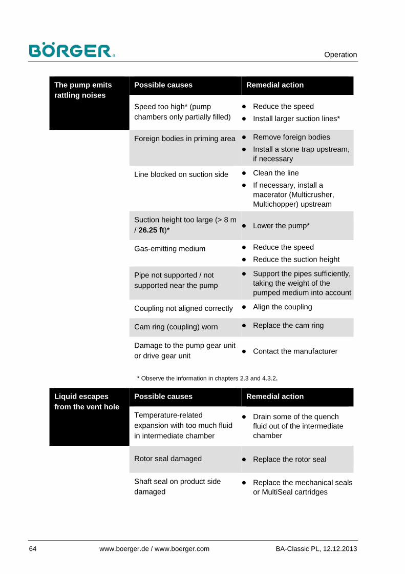
Operation
64 www.boerger.de / www.boerger.com BA-Classic PL, 12.12.2013
The pump emits rattling noises
Possible causes Remedial action
Speed too high* (pump chambers only partially filled)
● Reduce the speed ● Install larger suction lines*
Foreign bodies in priming area ● Remove foreign bodies ● Install a stone trap upstream,
if necessary
Line blocked on suction side ● Clean the line ● If necessary, install a
macerator (Multicrusher, Multichopper) upstream
Suction height too large (> 8 m / 26.25 ft)* ● Lower the pump*
Gas-emitting medium ● Reduce the speed ● Reduce the suction height
Pipe not supported / not supported near the pump
● Support the pipes sufficiently, taking the weight of the pumped medium into account
Coupling not aligned correctly ● Align the coupling
Cam ring (coupling) worn ● Replace the cam ring
Damage to the pump gear unit or drive gear unit ● Contact the manufacturer
* Observe the information in chapters 2.3 and 4.3.2.
Liquid escapes from the vent hole
Possible causes Remedial action
Temperature-related expansion with too much fluid in intermediate chamber
● Drain some of the quench fluid out of the intermediate chamber
Rotor seal damaged ● Replace the rotor seal
Shaft seal on product side damaged
● Replace the mechanical seals or MultiSeal cartridges

Operation
BA-Classic PL, 12.12.2013 www.boerger.de / www.boerger.com 65
Pump output below the nominal value
Possible causes Remedial action
Suction height too large (> 8 m / 26.25 ft)*
● Lower the pump*
Suction line diameter too large / too small*
● Adjust the pipe diameter to the pump output of the rotary lobe pump*
Pressure line diameter too small*
● Adjust the pipe diameter to the pump output of the rotary lobe pump*
Shut-off devices not open / not open completely, pipes blocked
● Open the shut-off devices ● Clean the pipes
Counter-pressure too high for other reasons
● Reduce the counter-pressure ● Install pressure monitoring
equipment
Speed too low* ● Increase the speed*
Viscosity of pumped medium too high*
● Reduce the viscosity when possible*
● Change the pump position* or install an auger upstream
Rotors have been destroyed
— By wear ● Replace the rotors
— By dry run ● Replace the rotors Notice: If the rotors were damaged due to dry run, the mechanical seals should also be replaced.
● Determine the cause of dry run and eliminate it
— By foreign bodies ● Replace the rotors ● Install a macerator
(Multicrusher, Multichopper) and a stone trap upstream, if necessary
Wear on casing liners ● Replace worn parts
* Observe the information in chapters 2.3 and 4.3.2.

Operation
66 www.boerger.de / www.boerger.com BA-Classic PL, 12.12.2013
Note
In the event of decreased pump output, Börger GmbH recommends first checking the condition of the rotors. Replace the rotors when they exhibit signs of significant wear. If these measures are not successful and the original pump output is still not reached following the installation of new rotors, the pump casing components must be inspected.
If one of the gear-side and cover-side casing protection plates exhibits significant signs of wear, it must be replaced, whereby the cover-side casing protection plate can be turned once before replacing it. If a gap still remains between the rotor body tips and the radial casing wall following the installation of new rotors – while the pump output remains too low – then we also recommend replacing the MIP radial casing liners if these are installed on the pump.
You have the option of retrofitting your pump with the innovative MIP casing and its replaceable, radial casing liners at a later date. Contact Börger customer service for more information.
Before replacing wear parts, take advantage of the possibility of increasing the speed of the pump drive (and thus, the pump output). On electric motors, this can be an increase in frequency on your frequency converter (this can also be above the mains frequency). For example, the speed can be varied on some drive types by adjusting the drive speed (hand wheel on the control gear motor or gas lever on the combustion motor) or oil quantity (on hydraulic drives). Consider the maximum loads as detailed in chapter 3.3.2. If in doubt, contact Börger customer service regarding the physical limitations of your unit.
Note
Contact Börger GmbH if there are other kinds of malfunctions / any other possible causes for malfunctions.

Maintenance and Repairs
BA-Classic PL, 12.12.2013 www.boerger.de / www.boerger.com 67
Maintenance and Repairs 6
The Maintenance and Repairs chapter is divided into sections on machine care, maintenance and inspection, and repairs.
The instructions described in this chapter are to be understood as the minimum requirements. Depending on the operating conditions, further work may be necessary to maintain the rotary lobe pump in an optimum condition.
Information on maintenance and repairs for special assemblies can be found in the supplier documentation in the appendix.
The maintenance and repair tasks detailed in this chapter may only be carried out by trained personnel employed by the operator.
Observe the assembly drawing, the spare parts list and the wear parts list in chapter 9.2 to 9.4 when carrying out repairs or ordering spare parts.
Any spare parts used must comply with the technical requirements specified by Börger GmbH, especially if they come into contact with the medium. This is always guaranteed when original spare parts are used. Only original spare parts may be used during the warranty period, failing which the warranty is void.
Read and strictly comply with the applicable regulations, manufacturer's safety data sheets and operator's instructions in respect of the storage, handling, use and disposal of oils, grease and other chemical substances.
Dispose of operating materials and replaced parts in a safe and environmentally-friendly manner.
Machine care 6.1Appropriate machine care helps to maintain the functionality of the rotary lobe pump unit on a long-term basis.
In general, regular cleaning of dust and deposits from all surfaces is sufficient.

Maintenance and Repairs
68 www.boerger.de / www.boerger.com BA-Classic PL, 12.12.2013
Caution!
Risk of burns!
The gear casing and, when the medium has reached certain temperatures, also the pump casing, can become hot and should not be touched during operation.
Only clean the rotary lobe pump when it is at a standstill.
Allow the rotary lobe pump to cool down completely, if necessary.
Avoid dust formation as this contributes to heat build-up.
Notice
Improper cleaning of the rotary lobe pump can lead to malfunctions and damage!
Do not use water jets.
Do not use aggressive cleaning agents, solvents or sandpaper, as these can damage the metallic and plastic surfaces, casing coating and seals.
Do not use metal objects such as scrapers and screwdrivers for cleaning coated machine parts.
Never clean sensitive components with hard scrubbing and strong mechanical pressure.
Only clean the rotary lobe pump by wiping or brushing it. Use ●lint-free cleaning cloths.
When required, use a standard aqueous industrial cleaner. ●
Keep all markings on the rotary lobe pump in a legible state at ●all times.

Maintenance and Repairs
BA-Classic PL, 12.12.2013 www.boerger.de / www.boerger.com 69
Maintenance and inspection 6.2 Maintenance and inspection plan 6.2.1
Note
Also observe the maintenance intervals detailed in the operating manuals for the drive, coupling, V-belts etc., which are included in the appendix.
In the event of a malfunction, shut down the rotary lobe pump immediately until the cause has been rectified.
The following intervals are guidelines. These intervals can be significantly reduced depending on the operating conditions.
Inspection / maintenance Interval (approx.)
Operating hours (approx.)
Measures
Cleaning the outer surfaces N See chapter 6.1 Machine care
Visual check for leaks* D 24 Replace the seals, if necessary
Audible check for smooth running D 24
Check the suction line, rectify any cavitation
Check the rotors and replace, if necessary
Checking the functions and flow rate W 168 Replace wear parts, if
necessary
Checking the oil level of the gear unit on the oil sight glass M 720 Refill, if necessary
Checking the pump and components for tight fit and possible damage
¼ Y 2160 Fasten loosened parts tightly, replace damaged parts
Checking the level of the quench fluid in the intermediate chamber
½ Y 4320 Refill, if necessary
Changing the lubricants 2 Y 10,000 See chapter 6.2.2
* Includes check of any overflowing quench fluid N = when necessary M = monthly D = daily Y = yearly W = weekly

Maintenance and Repairs
70 www.boerger.de / www.boerger.com BA-Classic PL, 12.12.2013
Lubricant fill level and changing the lubricants 6.2.2
The intervals for changing the lubricants can vary significantly and be reduced considerably depending on the operating conditions, such as high levels of humidity, high temperatures / temperature variations, aggressive atmospheres etc.
Caution!
Danger to health caused by contact with the pumped medium!
The quench fluid can contain pumped medium.
When using dangerous or health-endangering pumped media, take all necessary safety measures when draining and checking the fill level of the intermediate chamber.
Check the oil level and oil quality in the timing gear on the oil ●sight glass on a regular basis, according to chapter 6.2.1 or more often depending on the operating conditions. Also check the level and quality of the quench fluid in the intermediate chamber.
Use an oil dipstick, when necessary. ●
Note
The quench fluid can rise to the rim of the vent hole due to its quench function and depending on the operating temperature.
A leak of the mechanical seal can only be assumed if the liquid overflows. The fill levels specified below relate to optimal volumes of pure lubricants.

Maintenance and Repairs
BA-Classic PL, 12.12.2013 www.boerger.de / www.boerger.com 71
Fill levels: Mounting position
Type code 17th position
Gear unit Intermediate chamber
M1 standing 1 Center of oil sight glass
Top shaft, center to covered
M2 vertical 2 Completely filled1) Lower edge, test bore2)
M3 upside-down 3 Center of oil sight glass
Top shaft, center to covered
M5, M6 turned 90°
5, 6 Center of oil sight glass
Approximately up to the bend in the filler
1) In this case: Expansion of the gear oil caused by the temperature cannot be compensated. The operating temperature must not exceed the temperature specified in the order.
2) For submerged pumps: approx. 10 cm (3.94'') below the edge of the extension pipe
Change both lubricants after approximately 10,000 operating ●hours (or earlier, depending on the operating conditions) or after two years, whichever occurs first.
Change the lubricants earlier if they are heavily contaminated. ●
Notice
Risk of material damage caused by using wrong lubricants!
Observe the detailed specifications and instructions on changing the lubricants in the lubricant list in the appendix, which is part of this operating manual, as well as the specifications in the data sheet regarding the lubricants used.
Regarding the quench fluid, especially consider:
Due to the possibility, though unlikely, of quench fluid entering the pump chamber and thus intruding on the process itself, the quench fluid must be compatible with the pumped medium in addition to the other materials (O-rings).
Observe the repair instructions in chapter 6.3.1. ●
Shut down the rotary lobe pump. ●
Use a safe drip pan when draining used lubricant. ●

Maintenance and Repairs
72 www.boerger.de / www.boerger.com BA-Classic PL, 12.12.2013
Position of drain and fill holes: see chapter 3.1.7. ●
Observe the following fill quantities: ●
Fill quantities:
Mounting position Type code 17th position
Gear unit Intermediate chamber
M1 standing 1 approx. 1.5 l (.396 gal)
approx. 0.7 l (.185 gal)
M2 vertical 2 approx. 2.2 l (.581 gal)
approx. 0.8 l (.211 gal)
M3 upside-down 3 approx. 1.5 l (.396 gal)
approx. 0.7 l (.185 gal)
M5, M6 turned 90° 5, 6 approx. 1.0 l (.264 gal)
approx. 0.6 l (.159 gal)
Properly re-insert the screw plug with the sealing washer / the ●breather, with the opening facing downwards (cf. chapter 4.3.6).
Reattach the breather system on the gear unit correctly (cf. ●chapter 4.3.6).
When restarting after completing maintenance, observe the ●instructions in chapter 5.
Repairs 6.3 Notes on repair work 6.3.1
Warning!
Risk of serious hand injuries due to rotating parts!
Shut down the rotary lobe pump before carrying out repair work on the rotary lobe pump and accessories.
Secure the pump against accidental restart, e.g. by disconnecting the electrical drive from the power supply.
Maintenance and Repairs
BA-Classic PL, 12.12.2013 www.boerger.de / www.boerger.com 73
Warning!
Risk of serious injuries caused by pumped medium spouting out!
Liquid – when it is still pressurized – can spout out of the gap opening behind the cover while dismounting.
Therefore, wear protective clothing (gloves, goggles) when opening the cover and take all necessary precautions.
Warning!
Danger to health caused by contact with the pumped medium!
You may come into contact with the pumped medium when carrying out repair work.
Adhere to all possible safety regulations relating to the pumped medium.
When necessary, flush the pump and pipes before opening the quick-release cover.
Warning!
Risk of serious injuries caused by falling heavy parts!
Wear suitable protective clothing, especially safety shoes.
Secure heavy parts using suitable hoists.

Maintenance and Repairs
74 www.boerger.de / www.boerger.com BA-Classic PL, 12.12.2013
Caution!
Risk of burns!
The gear casing and, when the medium has reached certain temperatures, also the pump casing can become hot and should not be touched during operation.
Allow the system to cool down completely, if necessary.
Note
Observe the assembly drawing of the rotary lobe pump in chapter 9.3.
Repair work on the rotary lobe pump may only be carried out by qualified, authorized specialists employed by the operator.
Shut down the rotary lobe pump. ●
Close all valves and shut-off devices so that no pumped ●medium can enter the pump.
Only replace worn components, seals, screws, nuts etc., but ●especially the wetted parts, with original spare parts according to the following instructions.

Maintenance and Repairs
BA-Classic PL, 12.12.2013 www.boerger.de / www.boerger.com 75
Opening and closing the quick-release cover 6.3.2
1 Ring nut 2 Quick-release cover 4 Cover-side casing protection plate 5 Stud screw 6 O-ring The numbers indicated in brackets in the following chapter relate to this figure unless displayed in a more detailed figure next to the text.
Figure 6.3.2-1 Opening and closing the quick-release cover
All parts on the rotary lobe pump that are subject to wear are accessible after the quick-release cover has been removed.
Read and follow the safety instructions detailed in chapter ●6.3.1.
Switch off the drive and secure it against accidental restart. ●
Close all valves and shut-off devices so that no pumped ●medium can enter the pump.
Figure 6.3.2-2
Opening the quick-release cover:
● Use a suitable cover to prevent the medium from spouting out.
● Place a drip pan underneath.
● Loosen the four ring nuts (1) uniformly by approx. 5 mm (.20'') using a wrench.
● Initially, only open the cover (2) at the bottom (3 on standing versions) by a small gap (approx. 5 mm / .20'') to allow all residual pressure to escape and catch any pumped medium that spouts out.
● Completely undo the four ring nuts (1).
● Remove the quick-release cover (2).
● Remove the cover-side casing protection plate (4).

Maintenance and Repairs
76 www.boerger.de / www.boerger.com BA-Classic PL, 12.12.2013
Closing the quick-release cover:
● Check the O-ring (6). Replace the O-ring (6) if it shows signs of damage.
● Press the O-ring seal (6) carefully into position.
● Attach the cover-side casing protection plate (4).
● Push the quick-release cover (2) over the stud screws (5) and fasten it with the four ring nuts (1).
● Tighten the ring nuts (1) crosswise with uniform strength using a wrench. Take care not to damage the O-ring (6) or to push it out of position. Make sure that the ring nuts (1) are fastened tight enough so they cannot be loosened by hand.

Maintenance and Repairs
BA-Classic PL, 12.12.2013 www.boerger.de / www.boerger.com 77
Replacing the rotors 6.3.3
1 Rotor fastening screw, hexagon socket head cap screw
2 Premium rotor (linear)
type JS, JE (steel, stainless steel)
3 O-ring 4 Cover disk 5 Sealing washer 6 Grub screw 6.1 Threaded bore 7 Optimum rotor (screw profile)
types IS, IE (steel, stainless steel)
8 Optimum rotor (screw profile)
types I... (polymers) 9 Rotor (linear)
types A... (polymers) 10 Rotor (screw profile)
type D... (polymers) 11 Premium rotor (linear)
types J... (polymers) 12 O-ring 13 Special rotor fastening screw
with O-ring groove and hexagon socket
14 O-ring for rotating holding bush 15 Parallel key The numbers indicated in brackets in the following chapter relate to this figure unless displayed in a more detailed figure next to the text. Figure 6.3.3 Replacing the rotors

Maintenance and Repairs
78 www.boerger.de / www.boerger.com BA-Classic PL, 12.12.2013
Special tools required: A Rotor puller
For rotors made from steel or stainless steel: Z Auxiliary puller with
S Outer bores M Threaded bore
Notice
Risk of lasting damage due to
— improper cleaning
— switching on without rotors installed!
If the rotors are not properly installed, the parallel keys cannot reliably fix the rotating seal holding bushes. This may cause permanent damage to the rotary lobe pump.
Do not use pressurized fluid in the pump chamber for cleaning purposes.
Never switch the rotary lobe pump on, even for testing or cleaning, if the rotors are not properly installed, see also chapter 2.9.
● Shut down the rotary lobe pump and open the quick-release cover in accordance with chapter 6.3.2.
● Block the rotors by clamping an object with no sharp edges between the rotors, e.g. a lint-free cloth.
● Loosen the hexagon socket head cap screws (1, 13) on both rotors using a 14 mm hexagon socket wrench.
Polymer rotors (8, 9, 10, 11):
● Screw the rotor puller [A, spare parts list, position W2] into the bore of the respective rotor.

Maintenance and Repairs
BA-Classic PL, 12.12.2013 www.boerger.de / www.boerger.com 79
● Remove the rotor. For screw rotors (8, 10) use two rotor pullers [A] simultaneously and remove the screw rotors (8, 10) in pairs by pulling them off in alternate, uniform steps.
Rotors made from steel, stainless steel (2, 7):
● In each case, remove the sealing washer (5).
● Remove the respective cover disk (4) and O-ring (3) using a suitable hook or two slotted screwdrivers.
● Unscrew the grub screws (6) from the threaded bores (6.1) using a 6 mm hexagon socket wrench.
● Screw two screws (M12x30) into the threaded bores (6.1) of the grub screws (6) through the outer bores (S) of the auxiliary puller [Z].
● Screw the rotor puller [A] into the center bore (M) of the auxiliary puller [Z].
● Remove the rotor. For the screw rotors (7) use two rotor pullers [A] and auxiliary pullers [Z] simultaneously and remove the screw rotors (7) in pairs by pulling them off in alternate, uniform steps.
8
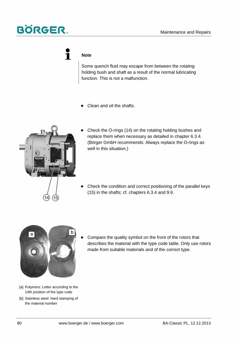
Maintenance and Repairs
80 www.boerger.de / www.boerger.com BA-Classic PL, 12.12.2013
Note
Some quench fluid may escape from between the rotating holding bush and shaft as a result of the normal lubricating function. This is not a malfunction.
● Clean and oil the shafts.
● Check the O-rings (14) on the rotating holding bushes and replace them when necessary as detailed in chapter 6.3.4. (Börger GmbH recommends: Always replace the O-rings as well in this situation.)
● Check the condition and correct positioning of the parallel keys (15) in the shafts; cf. chapters 6.3.4 and 9.6.
[a] Polymers: Letter according to the
14th position of the type code
[b] Stainless steel: Hard stamping of the material number
● Compare the quality symbol on the front of the rotors that describes the material with the type code table. Only use rotors made from suitable materials and of the correct type.
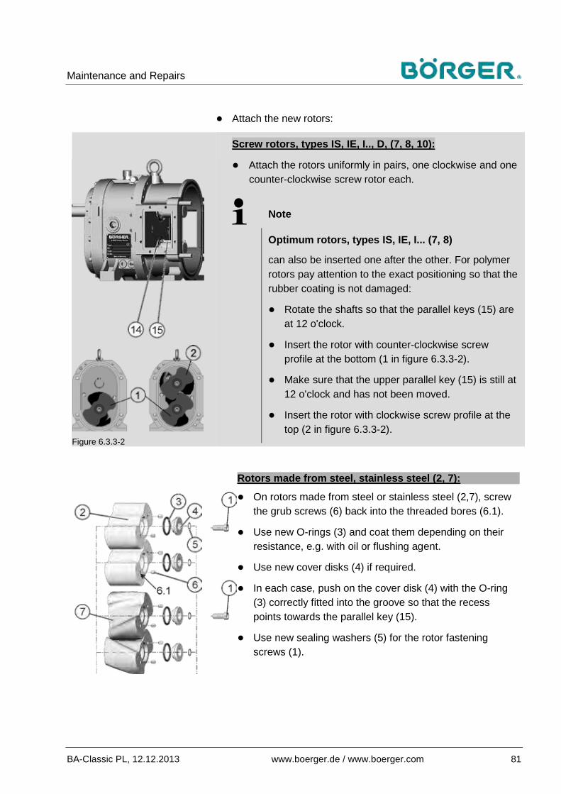
Maintenance and Repairs
BA-Classic PL, 12.12.2013 www.boerger.de / www.boerger.com 81
● Attach the new rotors:
Figure 6.3.3-2
Screw rotors, types IS, IE, I.., D, (7, 8, 10):
● Attach the rotors uniformly in pairs, one clockwise and one counter-clockwise screw rotor each.
Note
Optimum rotors, types IS, IE, I... (7, 8)
can also be inserted one after the other. For polymer rotors pay attention to the exact positioning so that the rubber coating is not damaged:
● Rotate the shafts so that the parallel keys (15) are at 12 o'clock.
● Insert the rotor with counter-clockwise screw profile at the bottom (1 in figure 6.3.3-2).
● Make sure that the upper parallel key (15) is still at 12 o'clock and has not been moved.
● Insert the rotor with clockwise screw profile at the top (2 in figure 6.3.3-2).
Rotors made from steel, stainless steel (2, 7):
● On rotors made from steel or stainless steel (2,7), screw the grub screws (6) back into the threaded bores (6.1).
● Use new O-rings (3) and coat them depending on their resistance, e.g. with oil or flushing agent.
● Use new cover disks (4) if required.
● In each case, push on the cover disk (4) with the O-ring (3) correctly fitted into the groove so that the recess points towards the parallel key (15).
● Use new sealing washers (5) for the rotor fastening screws (1).

Maintenance and Repairs
82 www.boerger.de / www.boerger.com BA-Classic PL, 12.12.2013
Premium polymer rotors, type J (11):
● Use new O-rings (12).
● Fit the O-rings (12) onto the rotor fastening screws (13) which have also been replaced if necessary. Ensure that each O-ring (12) is correctly fitted into the O-ring groove of the rotor fastening screw (13).
Screw in the suitable rotor fastening screws (1 or 13, with ●sealing washer / O-ring if required) and tighten them with a torque wrench.
Torque specifications
M16 steel screws, 10.9 180 Nm (1,593 in-lbs) M16 stainless steel screws A4-70 144 Nm (1,274 in-lbs) M16 Duplex 144 Nm (1,274 in-lbs)
Check that the newly installed rotors run smoothly. The ●easiest way of doing this is by turning the rotor on the drive shaft clockwise with an appropriate amount of force using a hexagon socket wrench or ratchet.
Note
"Smooth running" means a uniform, trouble-free true-running (concentricity) without any blocking.
When dry, fully rubber-coated rotors can only be rotated with a certain degree of force, as they are positioned close to the pump casing.
Providing the pumped medium and materials used allow this, the rotors can be coated with liquid (e.g. soft soap) for the smooth running check.
Attach the cover-side casing protection plate and quick-●release cover in accordance with chapter 6.3.2.
Before releasing the rotary lobe pump, a further short test run ●of the correct true-running must be made, e.g. by tapping the motor switch.

Maintenance and Repairs
BA-Classic PL, 12.12.2013 www.boerger.de / www.boerger.com 83
6.3.3.1 Replacing the rotors of PL 400
Figure 6.3.3.1 Replacing the rotors of PL400 The numbers indicated in brackets in the following chapter relate to this figure unless displayed in a more detailed figure next to the text.
Rotors, types JS, JE 2v Front rotors 2h Rear rotors
3 O-ring 4 Cover disk 5 Sealing washer 6 Grub screw 6.1 Threaded bore 14 Connecting sleeve 15 O-ring
Rotors, type A 9v Front rotor 9h Rear rotor 18 Connecting sleeve 19 O-ring Rotors, type D
10v Front rotor 10h Rear rotor 16 Connecting sleeve 17 O-ring Special tools:
A Puller Z, Z1 Auxiliary puller
On the PL 400 rotary lobe pump there are two rotors of series PL 200 on each shaft.
The rear rotors (toward the gear unit) of types A and D (9h, 10h) are modified designs with an open front.
A connecting sleeve with two O-rings tightly connects the front and the rear rotors.
Remove the front rotors as previously described in chapter ●6.3.3.

Maintenance and Repairs
84 www.boerger.de / www.boerger.com BA-Classic PL, 12.12.2013
For Premium rotors, types JS, JE, also remove the grub ●screws (6) on the rear rotors (2h).
Screw the threaded rods with nuts as a head (stop for the ●auxiliary puller) through the outer bores of the suitable auxiliary puller [Z, Z1] into the corresponding threaded bores of the respective rear rotor, in accordance with figure 6.3.3.1.
Screw the rotor puller [A] into the center bore of the auxiliary ●puller [Z, Z1], and then remove the rotor.
When attaching the rear rotors, and preparing to do so, ●proceed as described in chapter 6.3.3. For screw rotors observe the information at the end of this chapter.
Check the connecting sleeves (14, 16 or 18) and replace ●them, if necessary.
Replace the O-rings (15, 17 or 19). ●
Note
You can lubricate the O-rings and the connecting sleeves, depending on their resistance, with a type of oil or grease which is compatible with the medium to aid insertion.
Make sure that the O-rings are not pushed out of the O-ring groove during insertion.
You can use a plastic support and a plastic mallet, if necessary, but take care to insert the connecting sleeves equipped with O-rings evenly.
Insert the connecting sleeves (14, 16 or 18) with the fitted O-●rings (15, 17 or 19) into the front rotors.
Observe the details which were given in chapter 6.3.3 and ●push the new front rotor with the connecting sleeve inserted onto the shaft up to the stop on the rear rotor, if necessary by striking it lightly with a plastic mallet.
Complete installation and perform a smooth running check, as ●described in chapter 6.3.3.

Maintenance and Repairs
BA-Classic PL, 12.12.2013 www.boerger.de / www.boerger.com 85
Note
Screw rotors, type D (10):
The front pair and the rear pair of rotors each consist of a clockwise screw rotor (R) and a counter-clockwise screw rotor (L).
On each shaft, the screw profile direction of the front rotor (vR or vL) must be the opposite of the screw profile direction of the rear rotor (hL or hR).
The tips of the rotors are to be aligned with each other exactly.

Maintenance and Repairs
86 www.boerger.de / www.boerger.com BA-Classic PL, 12.12.2013
Replacing the mechanical seals 6.3.4
1 O-ring 2 Rotating seal holding bush 3 Shaft 4 Seal faces 5 O-ring 6 Lip seal 7 Gear-side casing protection
plate 8 Stationary seal holding bush 9 Parallel key 10 Fill hole on intermediate
chamber 10.1 Screw plug 10.2 Sealing washer 11 Drain from intermediate
chamber The numbers indicated in brackets in the following chapter relate to this figure unless displayed in a more detailed figure next to the text.
Figure 6.3.4-1 Replacing the mechanical seals
Special tool required: 12 Multitool — special tool for the rotating
holding bushes on one side, — push-in tool for the
mechanical seals on the other side (remove handle!)
In addition to the maintenance intervals detailed in chapter 6.2.1, replacement of the mechanical seals is necessary when pumped medium enters the intermediate chamber and the quench fluid escapes.
Switch off the drive and secure it against accidental restart. ●
Close all valves and shut-off devices. ●
12

Maintenance and Repairs
BA-Classic PL, 12.12.2013 www.boerger.de / www.boerger.com 87
Loosen the screw plug at the drain hole of the intermediate ●chamber (11) and drain the quench fluid from the intermediate chamber while adhering to the relevant safety precautions relating to the pumped medium and the quench fluid. See also chapter 3.1.7 regarding the position of the drain screw as well as chapter 6.2.2 and the lubricant list in the appendix for the quench fluid.
Thoroughly clean the intermediate chamber following a leak in ●the mechanical seal in order to remove all deposits of the pumped medium from the intermediate chamber and from in front of the lip seals (6). To do this, flush a suitable liquid (water, if appropriate, do not use high pressure!) through the fill hole (10) with the drain (11) open.
Open the quick-release cover according to chapter 6.3.2. ●
● Remove the rotors as detailed in chapter 6.3.3.
● Take precautions for pumps turned 90° to ensure the parallel key cannot fall into the inlet / outlet opening.
● Lift each of the parallel keys (9) out of the keyways of the shaft using a suitable tool (e.g. small lever). Make sure that the parallel keys are not damaged while doing this.
● Unscrew each rotating seal holding bush (2) using the special tool (Multitool, 12) and pull it off the shaft.
● Remove the seal face (4) with O-ring (5) out of the corresponding rotating seal holding bush (2).

Maintenance and Repairs
88 www.boerger.de / www.boerger.com BA-Classic PL, 12.12.2013
● Remove the seal faces (4) with O-rings (5) out of the stationary seal holding bushes (8) remaining in the pump using a suitable tool (e.g. small lever).
● Clean the O-ring seats with a suitable agent that is compatible with the seal material, quench fluid and pumped medium, e.g. alcohol-based industrial cleaner.
Notice
Risk of consequential damage caused by improper handling of the new seal faces!
Make sure not to damage the sealing surfaces of the new seal faces.
The sealing surfaces must be clean and should not be scratched.
● If delivered separately, fit the O-rings (5) onto the new seal faces (4). The mechanical seals are normally equipped with O-rings on delivery.
Notice
Risk of consequential damage caused by improper handling of the new O-rings!
The O-rings of a mechanical seal must be installed without oil or grease.
Otherwise, the sealing function is compromised.

Maintenance and Repairs
BA-Classic PL, 12.12.2013 www.boerger.de / www.boerger.com 89
Note
Generally, the mechanical seals equipped with O-rings can be inserted dry. In order to ensure that they are free of grease and to aid insertion, the O-rings can be sprayed lightly, depending on their resistance, with a quickly-volatilizing spray cleaner (degreaser) that leaves no residue.
● Press one seal face (4) with O-ring (5) into each rotating holding bush (2) using the push-in tool (Multitool, 12) for mechanical seals.
● Remove the pulling handle from the Multitool (12).
● Press both remaining seal faces (4) with O-rings (5) into the stationary holding bushes (8) using the push-in tool for mechanical seals (Multitool, 12).
● Lightly coat the clean sealing surfaces of the seal faces with suitable oil.
Notice
Risk of material damage if the rotating seal holding bushes are installed incorrectly!
First install one rotating holding bush with new mechanical seal completely according to the following description and secure the bush with the parallel key before installing the second rotating holding bush with new mechanical seal on the second shaft.
If the rotating holding bush with thread is not secured when the shafts are turned, the position of the holding bush can imperceptibly change while the second bush is being aligned. Use the special tool / Multitool for the installation.

Maintenance and Repairs
90 www.boerger.de / www.boerger.com BA-Classic PL, 12.12.2013
● Screw in the rotating holding bush (2) flush with the gear-side casing protection plate (7) and then unscrew it until the first groove is aligned with the keyway (figure 6.3.4-2). The rotating holding bush (2) should then protrude by approximately 0.2 mm (.008'').
Figure 6.3.4-2
Notice
Risk of consequential damage if the rotating seal holding bush (2) is unscrewed too far!
The pre-tension on the seal faces required for a correct seal is generated by the correct setting of the rotating holding bush.
Do not unscrew the rotating seal holding bush (2) too far.
● Insert the parallel key (9) so that it fits into the groove of the rotating seal holding bush (2) and the keyway of the shaft (3).
Note
If the parallel key only has one rounded side, then this must be fitted into the groove of the rotating holding bush (2). If the parallel key has a straight front, then this must point towards the quick-release cover. If the parallel key consists of two pieces, insert the parallel key rounded on both sides so that it fits into the rotating holding bush. Insert the second parallel key with the straight front pointing towards the quick-release cover.
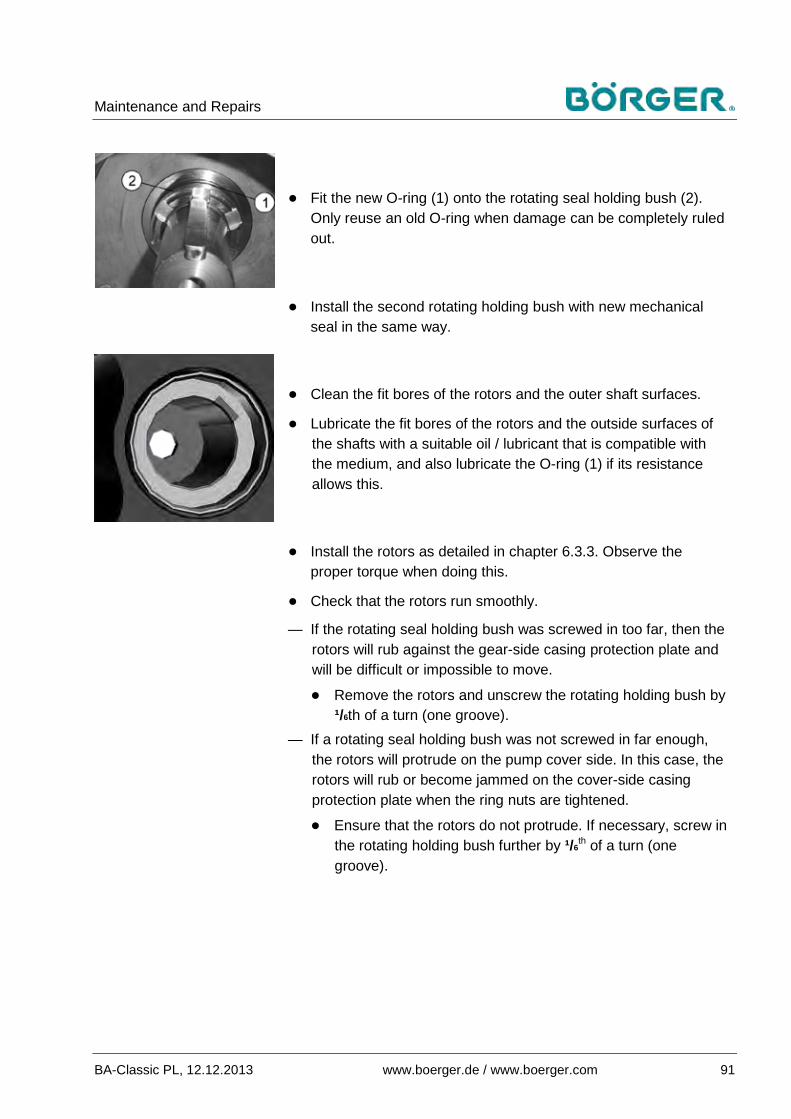
Maintenance and Repairs
BA-Classic PL, 12.12.2013 www.boerger.de / www.boerger.com 91
● Fit the new O-ring (1) onto the rotating seal holding bush (2). Only reuse an old O-ring when damage can be completely ruled out.
● Install the second rotating holding bush with new mechanical seal in the same way.
● Clean the fit bores of the rotors and the outer shaft surfaces.
● Lubricate the fit bores of the rotors and the outside surfaces of the shafts with a suitable oil / lubricant that is compatible with the medium, and also lubricate the O-ring (1) if its resistance allows this.
● Install the rotors as detailed in chapter 6.3.3. Observe the proper torque when doing this.
● Check that the rotors run smoothly.
— If the rotating seal holding bush was screwed in too far, then the rotors will rub against the gear-side casing protection plate and will be difficult or impossible to move.
● Remove the rotors and unscrew the rotating holding bush by ¹/6th of a turn (one groove).
— If a rotating seal holding bush was not screwed in far enough, the rotors will protrude on the pump cover side. In this case, the rotors will rub or become jammed on the cover-side casing protection plate when the ring nuts are tightened.
● Ensure that the rotors do not protrude. If necessary, screw in the rotating holding bush further by ¹/6
th of a turn (one groove).
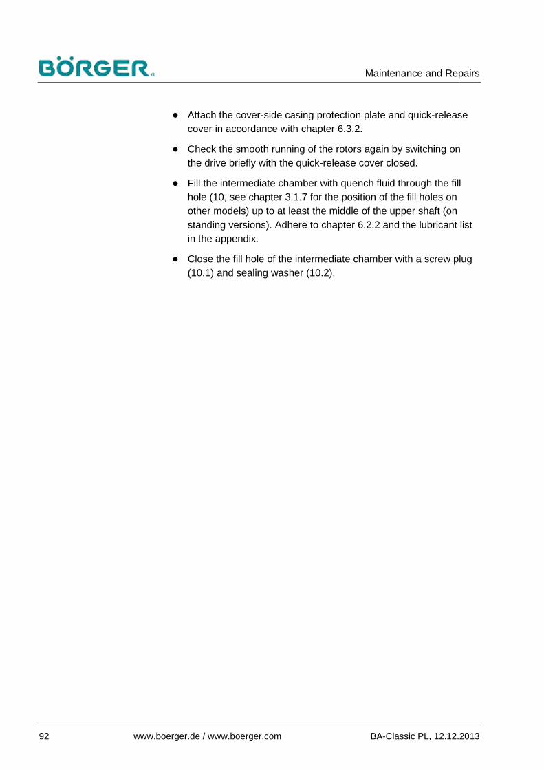
Maintenance and Repairs
92 www.boerger.de / www.boerger.com BA-Classic PL, 12.12.2013
● Attach the cover-side casing protection plate and quick-release cover in accordance with chapter 6.3.2.
● Check the smooth running of the rotors again by switching on the drive briefly with the quick-release cover closed.
● Fill the intermediate chamber with quench fluid through the fill hole (10, see chapter 3.1.7 for the position of the fill holes on other models) up to at least the middle of the upper shaft (on standing versions). Adhere to chapter 6.2.2 and the lubricant list in the appendix.
● Close the fill hole of the intermediate chamber with a screw plug (10.1) and sealing washer (10.2).

Maintenance and Repairs
BA-Classic PL, 12.12.2013 www.boerger.de / www.boerger.com 93
Replacing the casing liners (optional) 6.3.5
1 Hexagon socket head cap screw
2 Sealing washer 3 Clamping part 4 O-ring 5 Casing liners 6 O-ring groove
The numbers indicated in brackets in the following chapter relate to this figure unless displayed in a more detailed figure next to the text. Figure 6.3.5 Replacing the casing liners
Removing the casing liners
Shut down the rotary lobe pump and open the quick-release ●cover in accordance with chapter 6.3.2.
Note
The easiest way to remove the casing liners is to first remove the rotors as detailed in chapter 6.3.3.

Maintenance and Repairs
94 www.boerger.de / www.boerger.com BA-Classic PL, 12.12.2013
● Loosen the clamping parts (3) used to fix the casing liners (5) in the pump casing. To do this, loosen the hexagon socket head cap screws (1) above and below the inlet and outlet openings using a suitable hexagon socket wrench, i.e. PL 100, 200: 10 mm, PL 300, 400: 8 mm.
● The clamping parts (3) may not always loosen easily due to deposits of the pumped medium. In most cases, hitting the screw head lightly will loosen the clamping parts.
● Sealing washers (2) are located under the hexagon socket head cap screws (1). Replace these sealing washers.
● In order to prevent the rim [S] between the pump opening and O-ring groove (6) from being damaged, remove the O-ring (4) and clamp a parallel key [P] or a similar object in the O-ring groove (6) before using any tools.
● To remove the corresponding casing liner (5), lever out the liner carefully using a small lever or slotted screwdriver.
● Pull out the radial casing liner using a pair of tongs (e.g. pipe tongs).
Installing the casing liners
Clean the pump casing, clamping parts and contact surfaces. ●
Fasten the clamping parts (3) to the corresponding bores ●using the screws (1) and sealing washers (2), but do not tighten the screws yet.
Insert the casing liners (5) symmetrically into the pump ●casing. The casing liners (5) must be inserted into the gap between the gear-side casing protection plate (11 in the assembly drawing in chapter 9.3) and casing all the way to the stop at the rear wall. You can use a plastic mallet to aid insertion without damaging the casing liners (5). The complete front edge of the casing liner (5) must be flush with the pump casing.
Secure the casing liners (5) by tightening the hexagon socket ●head cap screws (1) alternately and uniformly with the appropriate torque.

Maintenance and Repairs
BA-Classic PL, 12.12.2013 www.boerger.de / www.boerger.com 95
Torque specifications
PL 100, 200 M 12 Steel 10.9
100 Nm (885 in-lbs)
Stainless steel A4-70 60 Nm (531 in-lbs)
PL 300, 400 M 10 Steel 10.9
50 Nm (443 in-lbs)
Stainless steel A4-70 40 Nm (354 in-lbs)
If you have removed the rotors, replace the O-rings on the ●rotating holding bushes (position 31 in the spare parts list) and, on PL 400, the O-rings on the connecting sleeves and reinstall the rotors as detailed in chapter 6.3.3. Observe the proper torque when doing this.
Check the smooth running of the rotors by turning the rotors ●by hand, see chapter 6.3.3.
Attach the cover-side casing protection plate and quick-●release cover in accordance with chapter 6.3.2.

Maintenance and Repairs
96 www.boerger.de / www.boerger.com BA-Classic PL, 12.12.2013
Replacing the gear-side casing protection plate 6.3.6
1 O-ring 2 Countersunk screw 3 Gear-side casing
protection plate 4 Jacking thread
Figure 6.3.6 Replacing the gear-side casing protection plate
Shut down the rotary lobe pump and open the quick-release ●cover in accordance with chapter 6.3.2.
Remove the rotors as detailed in chapter 6.3.3. ●
Unscrew the countersunk screws (2) from the gear-side casing ●protection plate (standard: 2 or 4 M8 / T40 Torx®screws, depending on the version).
Screw the countersunk screws (2) into the jacking threads (4) ●to loosen the casing protection plate, then remove the plate.
Clean any sealing compound from the rear wall of the pump ●casing.
Apply sealing compound (position W1 in the spare parts list) to ●that side of the new casing protection plate which faces away from the medium. Exception: no sealing compound is used on Longlife casing protection plates.
Insert the new gear-side casing protection plate and fasten it ●using the countersunk screws (2).
Replace the O-rings (1, position 31 in the spare parts list) on ●the rotating holding bushes.
Reinstall the rotors as detailed in chapter 6.3.3. Observe the ●proper torque when doing this.

Maintenance and Repairs
BA-Classic PL, 12.12.2013 www.boerger.de / www.boerger.com 97
Attach the cover-side casing protection plate and quick-●release cover in accordance with chapter 6.3.2.
Other repairs 6.3.7
If repairs to the rotary lobe pump are required that are not covered by the described repair and maintenance measures, we recommend contacting Börger customer service.
The factory can only accept repair orders if a completed safety certificate / declaration of decontamination accompany the device submitted for repair, as well as any necessary safety data sheets for the pumped medium and / or cleaning agent. The relevant form is also available as a download from our website under the service menu.
Queries 6.3.8
Börger rotary lobe pumps are easy to maintain. We hope that we have clearly described all the relevant operating steps in this operating manual. However, the applications and variations of Börger rotary lobe pumps are so multi-faceted that a general operating manual cannot answer all questions entirely.
If you have any questions, please contact Börger customer ●service. We will be happy to help.
We would also be grateful to receive feedback on any errors or unclear passages in this operating manual. This will help us to improve and develop this document and to offer you and all of our customers the best possible service.
Maintenance instructions for special equipment 6.3.9
Adhere to all possible supplementary operating manuals in the ●appendix.

Disposal
98 www.boerger.de / www.boerger.com BA-Classic PL, 12.12.2013
Disposal 7
Environmental protection 7.1
Caution!
Water-polluting materials
Such materials can pollute the soil and groundwater and enter the sewage system.
Comply with the legal obligations regarding waste avoidance and the proper recycling / disposal of waste during all work on and around the machine.
Water-polluting materials such as grease and lubricating oil must not pollute the soil or enter the sewage system, especially during installation, repair and maintenance work.
These materials must be collected, stored, transported and disposed of in suitable containers.
The applicable legal regulations must be strictly adhered to when disposing of operating materials or replacement materials during maintenance or decommissioning of the rotary lobe pump.
Oil, oily waste and grease 7.2Oil, oily waste and grease pose a significant risk to the environment. Therefore, disposal of such materials must be handled by a specialist company.
Collect any oil and oily waste and only dispose of them ●according to the legal requirements through authorized waste disposal companies / authorities.
Plastics 7.3 Sort any plastic waste as thoroughly as possible. ●
Dispose of plastics according to the legal requirements ●through authorized waste disposal companies / authorities.
Disposal
BA-Classic PL, 12.12.2013 www.boerger.de / www.boerger.com 99
Metals 7.4 Sort and separate different metal types. ●
Dispose of these metals according to the legal requirements ●through authorized waste disposal companies / authorities.
Electrical and electronic waste 7.5Electrical and electronic waste must be disposed of separately. Electrical and electronic waste must not be disposed of with domestic waste.
Only dispose of electrical or electronic waste according to the ●legal requirements through authorized waste disposal companies / authorities, e.g. recycling plants.
Final decommissioning 7.6 Check which materials can be recycled and make the ●
appropriate arrangements.

Accessories
100 www.boerger.de / www.boerger.com BA-Classic PL, 12.12.2013
Accessories 8
The range of pump accessories provided by Börger GmbH is as multi-faceted as the areas of application for the Börger rotary lobe pump. Only the most frequently requested equipment can be mentioned below.
If your rotary lobe pump was delivered with accessories, the corresponding operating manuals can generally be found in the appendix or in the packaging of the units, if delivered as originally packed.
Frequency converter 8.1Rotary lobe pumps can be operated with frequency converters.
As on all positive displacement pumps, only frequency converters that deliver a constant torque are suitable.
Note
An external drive cooler may be necessary if the motor frequency is set very low.
Monitoring equipment 8.2 Dry run protection with temperature sensor / conductivity sensor 8.2.1
Long dry run periods (i.e. operation without pumped medium) should be avoided. This especially applies to rotary lobe pumps with rubber-coated rotors. Components on the rotary lobe pump are damaged when frictional heat is generated.
In processes in which dry running cannot be fully excluded, e.g. when containers are emptied using the rotary lobe pump, dry run protection is recommended through a temperature sensor or a conductivity sensor as a level control indicator, both in combination with a connected controller.

Accessories
BA-Classic PL, 12.12.2013 www.boerger.de / www.boerger.com 101
Temperature sensor: If the temperature in the pump chamber rises to a preset value due to a lack of pumped medium, the rotary lobe pump / system is switched off by means of a control unit. This then prevents the rotary lobe pump from running dry. PT100 temperature sensors and control units are available from Börger GmbH.
Conductivity sensors measure the electrical conductivity on the pump inlet and switch the rotary lobe pump / system off by means of a control unit when the value drops beneath a specified limit.
Pressure monitoring devices as overpressure protection 8.2.2
Exceeding the permissible maximum pressure can cause lasting damage to parts of the rotary lobe pump and all components. There is also a risk of leakage and subsequent risks to personnel and the environment, depending on the pumped medium.
Pressure switches / pressure monitoring devices offer protection against damage caused by overpressure. They are used to switch off the rotary lobe pump or system automatically when a preset pressure is exceeded, or to carry out other measures for reducing the pressure.
Pressure relief valve with bypass 8.2.3
By using a bypass with pressure relief valve (safety valve), it is possible to close the pressure line completely for a short period without switching off the pump.
While the pressure line is closed, the pump delivers the medium back to the suction side through the opened pressure relief valve. The causes of overpressure can now be rectified.
When the pressure decreases and the pressure line opens again, the pressure relief valve closes and operation can be continued without delay.

Accessories
102 www.boerger.de / www.boerger.com BA-Classic PL, 12.12.2013
Level monitor with float switch 8.2.4
Float switches and floating magnetic switches are used for monitoring or controlling the fill level, and can also be used for dry run protection (depending on the version).
The Condor PSN-X float switch with converter (no protective ground connection) is often used for monitoring the pump processes of filling and emptying, and is stocked by Börger GmbH.
Auger feed 8.3An auger feed installed in front of the pump inlet with a feed hopper allows non-flowing media that are just able to be pumped to be conveyed in certain cases.

Appendix
BA-Classic PL, 12.12.2013 www.boerger.de / www.boerger.com 103
Appendix 9
Data sheet 9.1The data sheet is included separately from the operating manual.
The data sheet contains all relevant data for your Börger rotary lobe pump.
Wear parts 9.2The following wear parts list includes the quantity, designation and position number (see assembly drawing in chapter 9.3) of the pump elements that are replaced during the corresponding installation and repair work. The complete spare parts list with article numbers (important when ordering) is found in chapter 9.4.
The rotor type and corresponding materials are indicated by the type code on the nameplate of the pump or unit (see chapters 2.6 and 9.5).
The required number of individual parts will to some extent depend on your rotary lobe pump version. Take note of the number of parts removed from the rotary lobe pump. Please contact Börger GmbH if you have any questions on this matter.
Rotor replacement Quantity Unit Designation Pos. no. 2 piece(s) Rotors (front rotors on PL 400) 9... 0 / 2 piece(s) Rear rotors for PL 400 9.4b, 9.6e, 9.7b 0 / 2 piece(s) Connecting sleeve for rotors on PL 400 9.4c, 9.6c, 9.7c 0 / 4 piece(s) O-ring 55x3 for connecting sleeve on PL 400 9.4d, 9.6d, 9.7d 1 piece(s) O-ring 250x7 for quick-release cover 30 2 piece(s) O-ring 54x4 for rotating holding bush 31
0 / 2 piece(s) O-ring 54x4 for cover disk on Premium and Optimum rotors made from steel or stainless steel (types JS, JE, IS, IE) 32
0 / 2 piece(s) Cover disk for Premium and Optimum rotors made from steel or stainless steel (types JS, JE, IS, IE) 24
0 / 2 piece(s) Rotor fastening screw M16x40 64.1
piece(s) Special rotor fastening screw M16x40 with O-ring groove, for PFA rotors, type J 64.2a
0 / 2 piece(s)
Sealing washer for rotor fastening screw on Premium and Optimum rotors made from steel or stainless steel (types JS, JE, IS, IE)
74
piece(s) O-ring for rotor fastening screw on PFA rotors, type J 64.2b
Appendix
104 www.boerger.de / www.boerger.com BA-Classic PL, 12.12.2013
Replacement of casing protection: Quantity Unit Designation Pos. no. 1 piece(s) Cover-side casing protection plate 10 1 piece(s) Gear-side casing protection plate 11 0 / 2 piece(s) Casing liners 12.a 0 / 4 / 8 piece(s) Hexagon socket head cap screw for clamping parts 12.c
0 / 4 / 8 piece(s) Sealing washer for hexagon socket head cap screw on clamping part 12.d
1 piece(s) O-ring 250x7 for quick-release cover 30 2 piece(s) O-ring 54x4 for rotating holding bush 31
0 / 2 piece(s) O-ring 54x4 for cover disk on Premium and Optimum rotors made from steel or stainless steel (types JS, JE, IS, IE) 32
2 / 4 piece(s) Countersunk screw M8x16 (Standard: Torx) for casing protection plate 52
0 / 2
piece(s) O-ring for rotor fastening screw on PFA rotors, type J 64.2b
piece(s) Sealing washer for rotor fastening screw on Premium and Optimum rotors made from steel or stainless steel (types JS, JE, IS, IE)
74
0 / 4 piece(s) O-ring 55x3 for connecting sleeve on PL 400 9.4d, 9.6d, 9.7d
Replacement of mechanical seal: Quantity Unit Designation Pos. no. 2 piece(s) Mechanical seal (2 seal faces, 2 O-rings) 15 1 piece(s) O-ring 250x7 for quick-release cover 30 2 piece(s) O-ring 54x4 for rotating holding bush 31
0 / 2 piece(s) O-ring 54x4 for cover disk on Premium and Optimum rotors made from steel or stainless steel (types JS, JE, IS, IE) 32
0 / 2
piece(s) O-ring for rotor fastening screw on PFA rotors, type J 64.2b
piece(s) Sealing washer for rotor fastening screw on Premium and Optimum rotors made from steel or stainless steel (types JS, JE, IS, IE)
74
0 / 4 piece(s) O-ring 55x3 for connecting sleeve on PL 400 9.4d, 9.6d, 9.7d
Installation aids:
— Rotor puller (spare parts list, position W2) — Additionally for rear rotors on PL 400: Auxiliary puller (spare
parts list, position W3.2) — Multitool (spare parts list, position W4), with special tool for
rotating holding bushes on one side and push-in tool for mechanical seals on the other.

Appendix
BA-Classic PL, 12.12.2013 www.boerger.de / www.boerger.com 105
Note on ordering spare parts
You can order spare parts by quoting the article number from the enclosed spare parts list.
You can also quote the type code and serial number on the nameplate of the rotary lobe pump when ordering. Börger GmbH will then obtain the information for the appropriate spare parts for you from the production documents of your rotary lobe pump.
Record all modifications made to the pump equipment after the initial delivery in the type code table, such as changes to the rotor material and / or type (see chapter 9.5).
In order to avoid incorrect deliveries, always quote all modifications made when ordering spare parts.
Assembly drawing 9.3The assembly drawing shows the positions of the spare parts detailed in the spare parts list (chapter 9.4).
The most common wear parts are distinguished by a black border around the position number (see chapter 9.2).

Appendix
106 www.boerger.de / www.boerger.com BA-Classic PL, 12.12.2013
Figure 9.3-1 PL assembly drawing

Appendix
BA-Classic PL, 12.12.2013 www.boerger.de / www.boerger.com 107
Figure 9.3-2 Tools

Appendix
108 www.boerger.de / www.boerger.com BA-Classic PL, 12.12.2013
Complete spare parts list 9.4The spare parts list is universal and contains many variations of the pump elements. The positioning of the parts can be seen in the assembly drawing. The elements used in your rotary lobe pump are defined according to the type code and all additional specifications in the data sheet.
Observe the article numbers in the separate parts list of the order for special versions, e.g. steel / stainless steel rotors with temperature-dependent undersizes for applications in explosive areas.
Pos. Art. no. Item description Material Quantity PL …
..100 ..200 ..300 ..400
1 A20008-5 Gear casing PL EN-JL1040 (~ASTM A48-40 B, UNS F12801) 1 1 1 1
2 A20109 Gear casing cover for top or bottom drive shaft EN-JL1040 (~ASTM A48-40 B, UNS F12801) 1 1 1 1
A20111 Gear casing cover for top and bottom drive shaft EN-JL1040 (~ASTM A48-40 B, UNS F12801) 1 1 1 1
A20110 Gear casing cover for top or bottom drive shaft with bores for hydraulic lantern
EN-JL1040 (~ASTM A48-40 B, UNS F12801) 1 1 1 1
A20113 Gear casing cover for top or bottom drive shaft, with bores for hydraulic lantern and additional bore G½ for mounting position M2
EN-JL1040 (~ASTM A48-40 B, UNS F12801) 1 1 1 1
5 B40118-5 Pump casing, PL 100 EN-JL1040 (~ASTM A48-40 B, UNS F12801) 1 — — —
B40138-5 Pump casing, PL 100 1.4517 (~ASTM A 890) 1 — — —
B40430-5 Pump casing, MIP, PL 100 EN-JL1040 (~ASTM A48-40 B, UNS F12801) 1 — — —
B40130-5 Pump casing, MIP, PL 100 1.4517 (~ASTM A 890) 1 — — —
B40218-5 Pump casing, PL 200 EN-JL1040 (~ASTM A48-40 B, UNS F12801) — 1 — —
B40238-5 Pump casing, PL 200 1.4517 (~ASTM A 890) — 1 — —
B40440-5 Pump casing, MIP, PL 200 EN-JL1040 (~ASTM A48-40 B, UNS F12801) — 1 — —
B40230-5 Pump casing, MIP, PL 200 1.4517 (~ASTM A 890) — 1 — —
B40318-5 Pump casing, PL 300 EN-JL1040 (~ASTM A48-40 B, UNS F12801) — — 1 —
B40338-5 Pump casing, PL 300 1.4517 (~ASTM A 890) — — 1 —
B40450-5 Pump casing, MIP, PL 300 EN-JL1040 (~ASTM A48-40 B, UNS F12801) — — 1 —
B40330-5 Pump casing, MIP, PL 300 1.4517 (~ASTM A 890) — — 1 —
B40418-5 Pump casing, PL 400 EN-JL1040 (~ASTM A48-40 B, UNS F12801) — — — 1
B40460-5 Pump casing, MIP, PL 400 EN-JL1040 (~ASTM A48-40 B, UNS F12801) — — — 1
8 B41008 Quick-release cover for pump casing EN-JS1030 (~ASTM A536, 60-40-18, UNS F32800) 1 1 1 1
B41008PT Quick-release cover with groove for PT 100 for pump casing
EN-JS1030 (~ASTM A536, 60-40-18, UNS F32800) 1 1 1 1
B41009 Quick-release cover for pump casing 1.4517 (~ASTM A 890) 1 1 1 1
B41009PT Pump casing cover with groove for PT 100 1.4517 (~ASTM A 890) 1 1 1 1

Appendix
BA-Classic PL, 12.12.2013 www.boerger.de / www.boerger.com 109
Pos. Art. no. Item description Material Quantity PL …
..100 ..200 ..300 ..400 9.4 R82468 Rotor, dual-lobe, linear, PL 100 NBR 2 — — —
R82478 Rotor, dual-lobe, linear, PL 100 EPDM 2 — — —
R82458 Rotor, dual-lobe, linear, PL 100 FKM 2 — — —
R82488 Rotor, dual-lobe, linear, PL 100 CSM 2 — — —
R82783 Rotor, dual-lobe, linear, PL 100 PUR, black — 2 — —
R82568 Rotor, dual-lobe, linear, PL 200 NBR — 2 — 2
R82578 Rotor, dual-lobe, linear, PL 200 EPDM — 2 — 2
R82558 Rotor, dual-lobe, linear, PL 200 FKM — 2 — 2
R82793 Rotor, dual-lobe, linear, PL 200 PUR, black — 2 — 2
R82588 Rotor, dual-lobe, linear, PL 200 CSM — 2 — —
R82618 Rotor, dual-lobe, linear, PL 300 NBR — — 2 —
R82628 Rotor, dual-lobe, linear, PL 300 EPDM — — 2 —
R82608 Rotor, dual-lobe, linear, PL 300 FKM — — 2 —
R82638 Rotor, dual-lobe, linear, PL 300 CSM — — 2 —
9.4b R82569 Rotor, dual-lobe, linear, open front NBR — — — 2
R82579 Rotor, dual-lobe, linear, open front EPDM — — — 2
R82559 Rotor, dual-lobe, linear, open front FKM — — — 2
R82794 Rotor, dual-lobe, linear, open front PUR, black — — — 2
9.4c C79900 Connecting sleeve for rotors, type A and D, on PL 400 1.7225 (~AISI 4140/4142) — — — 2
C79902 Connecting sleeve for rotors, type A and D, on PL 400 1.4571 (~AISI 316 Ti) — — — 2
9.4d O55705 O-ring 55x3 for connecting sleeve PL400 NBR — — — 4
O55715 O-ring 55x3 for connecting sleeve PL400 EPDM — — — 4
O55725 O-ring 55x3 for connecting sleeve PL400 FKM — — — 4
9.5 R8840L9 Optimum rotor, dual-lobe, screw profile, ccw, PL 100 NBR 1 — — —
R8840R9 Optimum rotor, dual-lobe, screw profile, cw, PL 100 NBR 1 — — —
R8842L9 Optimum rotor, dual-lobe, screw profile, ccw, PL 100 EPDM 1 — — — R8842R9 Optimum rotor, dual-lobe, screw profile, cw, PL 100 EPDM 1 — — —
R8844L9 Optimum rotor, dual-lobe, screw profile, ccw, PL 100 FKM 1 — — — R8844R9 Optimum rotor, dual-lobe, screw profile, cw, PL 100 FKM 1 — — —
R8850L9 Optimum rotor, dual-lobe, screw profile, ccw, PL 200 NBR — 1 — — R8850R9 Optimum rotor, dual-lobe, screw profile, cw, PL 200 NBR — 1 — —
R8852L9 Optimum rotor, dual-lobe, screw profile, ccw, PL 200 EPDM — 1 — — R8852R9 Optimum rotor, dual-lobe, screw profile, cw, PL 200 EPDM — 1 — —
R8854L9 Optimum rotor, dual-lobe, screw profile, ccw, PL 200 FKM — 1 — —
R8854R9 Optimum rotor, dual-lobe, screw profile, cw, PL 200 FKM — 1 — —
R8860L9 Optimum rotor, dual-lobe, screw profile, ccw, PL 300 NBR — — 1 — R8860R9 Optimum rotor, dual-lobe, screw profile, cw, PL 300 NBR — — 1 —
R8862L9 Optimum rotor, dual-lobe, screw profile, ccw, PL 300 EPDM — — 1 —
R8862R9 Optimum rotor, dual-lobe, screw profile, cw, PL 300 EPDM — — 1 —
R8864L9 Optimum rotor, dual-lobe, screw profile, ccw, PL 300 FKM — — 1 — R8864R9 Optimum rotor, dual-lobe, screw profile, cw, PL 300 FKM — — 1 —
9.5a On request Optimum rotor, dual-lobe, screw profile, ccw, PL 100 Steel 1 — — —
On request Optimum rotor, dual-lobe, screw profile, cw, PL 100 Steel 1 — — —
On request Optimum rotor, dual-lobe, screw profile, ccw, PL 100 1.4404 (~AISI 316 L, UNS S31603) 1 — — —
On request Optimum rotor, dual-lobe, screw profile, cw, PL 100 1.4404 (~AISI 316 L, UNS S31603) 1 — — —
On request Optimum rotor, dual-lobe, screw profile, ccw, PL 200 Steel — 1 — —
On request Optimum rotor, dual-lobe, screw profile, cw, PL 200 Steel — 1 — —
R8855L9 Optimum rotor, dual-lobe, screw profile, ccw, PL 200 1.4404 (~AISI 316 L, UNS — 1 — —

Appendix
110 www.boerger.de / www.boerger.com BA-Classic PL, 12.12.2013
Pos. Art. no. Item description Material Quantity PL …
..100 ..200 ..300 ..400 S31603)
R8855R9 Optimum rotor, dual-lobe, screw profile, cw, PL 200 1.4404 (~AISI 316 L, UNS S31603) — 1 — —
On request Optimum rotor, dual-lobe, screw profile, ccw, PL 300 Steel — — 1 — On request Optimum rotor, dual-lobe, screw profile, cw, PL 300 Steel — — 1 —
On request Optimum rotor, dual-lobe, screw profile, ccw, PL 300 1.4404 (~AISI 316 L, UNS S31603) — — 1 —
On request Optimum rotor, dual-lobe, screw profile, cw, PL 300 1.4404 (~AISI 316 L, UNS S31603) — — 1 —
9.5b Z41160 Grub screw M12x16, DIN EN ISO 4027 Steel, galvanized 4 4 4 —
Z41162 Grub screw M12x16, DIN EN ISO 4027 Stainless steel 4 4 4 —
9.6 R89215 Premium rotor, dual-lobe, linear, PL 100 PFA black 2 — — —
R89227 Premium rotor, dual-lobe, linear, PL 200 PFA black — 2 — —
R89233 Premium rotor, dual-lobe, linear, PL 300 PFA black — — 2 —
R89235 Premium rotor, dual-lobe, linear, PL 300 PFA white — — 2 —
9.6a R89210 Premium rotor, dual-lobe, linear, PL 100 1.7225 (~AISI 4140/4142) 2 — — —
R89212 Premium rotor, dual-lobe, linear, PL 100 1.4404 (~AISI 316 L, UNS S31603) 2 — — —
R89314 Premium rotor, dual-lobe, linear, PL 100 1.4539 (~AISI 904 L, UNS N 08904) 2 — — —
R89220 Premium rotor, dual-lobe, linear, PL 200 1.7225 (~AISI 4140/4142) — 2 — 4
R89222 Premium rotor, dual-lobe, linear, PL 200 1.4404 (~AISI 316 L, UNS S31603) — 2 — 4
R89324 Premium rotor, dual-lobe, linear, PL 200 1.4539 (~AISI 904 L, UNS N 08904) — 2 — 4
R89230 Premium rotor, dual-lobe, linear, PL 300 1.7225 (~AISI 4140/4142) — — 2 —
R89232 Premium rotor, dual-lobe, linear, PL 300 1.4404 (~AISI 316 L, UNS S31603) — — 2 —
9.6b Z41160 Grub screw M12x16, DIN EN ISO 4027 Steel, galvanized 4 4 4 8
Z41162 Grub screw M12x16, DIN EN ISO 4027 Stainless steel 4 4 4 8
9.6c C79904 Connecting sleeve for Premium rotors on PL 400 1.7225 (~AISI 4140/4142) — — — 2
C79919 Connecting sleeve for Premium rotors on PL 400 1.4571 (~AISI 316 Ti) — — — 2
9.6d O55705 O-ring 55x3 for connecting sleeve PL400 NBR — — — 4
O55715 O-ring 55x3 for connecting sleeve PL400 EPDM — — — 4
O55725 O-ring 55x3 for connecting sleeve PL400 FKM — — — 4
9.7 R9323L9 Rotor, tri-lobe, screw profile, ccw, PL 100 NBR 1 — — — R9323R9 Rotor, tri-lobe, screw profile, cw, PL 100 NBR 1 — — —
R9324L9 Rotor, tri-lobe, screw profile, ccw, PL 100 EPDM 1 — — —
R9324R9 Rotor, tri-lobe, screw profile, cw, PL 100 EPDM 1 — — —
R9325L9 Rotor, tri-lobe, screw profile, ccw, PL 100 FKM 1 — — — R9325R9 Rotor, tri-lobe, screw profile, cw, PL 100 FKM 1 — — —
R9327L9 Rotor, tri-lobe, screw profile, ccw, PL 200 NBR — 1 — 1 R9327R9 Rotor, tri-lobe, screw profile, cw, PL 200 NBR — 1 — 1
R9328L9 Rotor, tri-lobe, screw profile, ccw, PL 200 EPDM — 1 — 1 R9328R9 Rotor, tri-lobe, screw profile, cw, PL 200 EPDM — 1 — 1
R9329L9 Rotor, tri-lobe, screw profile, ccw, PL 200 FKM — 1 — 1 R9329R9 Rotor, tri-lobe, screw profile, cw, PL 200 FKM — 1 — 1
R9330L9 Rotor, tri-lobe, screw profile, ccw, PL 200 NR/SBR — 1 — —
R9330R9 Rotor, tri-lobe, screw profile, cw, PL 200 NR/SBR — 1 — —
R9331L9 Rotor, tri-lobe, screw profile, ccw, PL 300 NBR — — 1 — R9331R9 Rotor, tri-lobe, screw profile, cw, PL 300 NBR — — 1 —

Appendix
BA-Classic PL, 12.12.2013 www.boerger.de / www.boerger.com 111
Pos. Art. no. Item description Material Quantity PL …
..100 ..200 ..300 ..400 R9332L9 Rotor, tri-lobe, screw profile, ccw, PL 300 EPDM — — 1 — R9332R9 Rotor, tri-lobe, screw profile, cw, PL 300 EPDM — — 1 —
R9333L9 Rotor, tri-lobe, screw profile, ccw, PL 300 FKM — — 1 — R9333R9 Rotor, tri-lobe, screw profile, cw, PL 300 FKM — — 1 —
R9334L9 Rotor, tri-lobe, screw profile, ccw, PL 300 NR/SBR — — 1 — R9334R9 Rotor, tri-lobe, screw profile, cw, PL 300 NR/SBR — — 1 —
9.7b R9335L9 Rotor, tri-lobe, screw profile, ccw, open front, with spacer ring NBR — — — 1
R9335R9 Rotor, tri-lobe, screw profile, cw, open front, with spacer ring NBR — — — 1
R9339L9 Rotor, tri-lobe, screw profile, ccw, open front, with spacer ring FKM — — — 1
R9339R9 Rotor, tri-lobe, screw profile, cw, open front, with spacer ring FKM — — — 1
R9338L9 Rotor, tri-lobe, screw profile, ccw, open front, with spacer ring EPDM — — — 1
R9338R9 Rotor, tri-lobe, screw profile, cw, open front, with spacer ring EPDM — — — 1
9.7c C79900 Connecting sleeve for rotors, type A and D, on PL 400 1.7225 (~AISI 4140/4142) — — — 2
C79902 Connecting sleeve for rotors, type A and D, on PL 400 1.4571 (~AISI 316 Ti) — — — 2
9.7d O55705 O-ring 55x3 for connecting sleeve PL400 NBR — — — 4
O55715 O-ring 55x3 for connecting sleeve PL400 EPDM — — — 4
O55725 O-ring 55x3 for connecting sleeve PL400 FKM — — — 4
10 B41018 Cover-side casing protection plate 1.8714 (~XAR 400) 1 1 1 1
B41028 Cover-side casing protection plate 1.4571 (~AISI 316 Ti) 1 1 1 1
B41028P Cover-side casing protection plate 1.4571 (~AISI 316 Ti) plasma hardened 1 1 1 1
B41037 Cover-side casing protection plate, specially for O-ring FFKM 248x3 mm, item no. O45439 1.4571 (~AISI 316 Ti) 1 1 1 1
B41032 Cover-side casing protection plate 1.4539 (~AISI 904 L, UNS N 08904) 1 1 1 1
B41042 Cover-side casing protection plate SiSiC 1 1 1 1
B41018K Cover-side casing protection plate Ceramic coated 1 1 1 1
11 B41058 Gear-side casing protection plate 1.7225 (~AISI 4140/4142) 1 1 1 1
B41058k Gear-side casing protection plate Ceramic coated 1 1 1 1
B51056 Gear-side casing protection plate (4 fixing bores) 1.4571 (~AISI 316 Ti) 1 1 1 1
B51056P Gear-side casing protection plate (4 fixing bores)
1.4571 (~AISI 316 Ti) plasma hardened 1 1 1 1
B51059 Gear-side casing protection plate (4 fixing bores)
1.4539 (~AISI 904 L, UNS N 08904) 1 1 1 1
B41059 Longlife gear-side casing protection plate Ceramic composite 1 1 1 1
B41057 Gear-side casing protection plate, with fiber barrier edge 1.7225 (~AISI 4140/4142) 1 1 1 1
B41056 Gear-side casing protection plate, with fiber barrier edge 1.4571 (~AISI 316 Ti) 1 1 1 1
B41068 Gear-side casing protection plate for rotating holding bush with backflush grooves 1.7225 (~AISI 4140/4142) 1 1 1 1
B51064 Gear-side casing protection plate for rotating holding bush with backflush grooves 1.4571 (~AISI 316 Ti) 1 1 1 1

Appendix
112 www.boerger.de / www.boerger.com BA-Classic PL, 12.12.2013
Pos. Art. no. Item description Material Quantity PL …
..100 ..200 ..300 ..400 12.a B41060 Casing liner, PL 100 1.8714 (~XAR 400) 2 — — —
B41100 Casing liner, PL 100 1.4571 (~AISI 316 Ti) 2 — — —
B41102 Casing liner, PL 100 1.4539 (~AISI 904 L, UNS N 08904) 2 — — —
B41100P Casing liner, PL 100 1.4571 (~AISI 316 Ti) plasma hardened 2 — — —
B41070 Casing liner, PL 200 1.8714 (~XAR 400) — 2 — —
B41110 Casing liner, PL 200 1.4571 (~AISI 316 Ti) — 2 — —
B41112 Casing liner, PL 200 1.4539 (~AISI 904 L, UNS N 08904) — 2 — —
B41110P Casing liner, PL 200 1.4571 (~AISI 316 Ti) plasma hardened — 2 — —
B41080 Casing liner, PL 300 1.8714 (~XAR 400) — — 2 —
B41120 Casing liner, PL 300 1.4571 (~AISI 316 Ti) — — 2 —
B41122 Casing liner, PL 300 1.4539 (~AISI 904 L, UNS N 08904) — — 2 —
B41120P Casing liner, PL 300 1.4571 (~AISI 316 Ti) plasma hardened — — 2 —
B41090 Casing liner, PL 400 1.8714 (~XAR 400) — — — 2
B41130 Casing liner, PL 400 1.4571 (~AISI 316 Ti) — — — 2
B41130P Casing liner, PL 400 1.4571 (~AISI 316 Ti) plasma hardened — — — 2
12.b B41140 Clamping part, ccw, PL 100 1.0038 (~ASTM A570-36) 2 — — — B41143 Clamping part, cw, PL 100 1.0038 (~ASTM A570-36) 2 — — —
B41270 Clamping part, ccw, PL 100 1.4571 (~AISI 316 Ti) 2 — — —
B41273 Clamping part, cw, PL 100 1.4571 (~AISI 316 Ti) 2 — — —
B41400 Clamping part, ccw, PL 100 1.4539 (~AISI 904 L, UNS N 08904) 2 — — —
B41403 Clamping part, cw, PL 100 1.4539 (~AISI 904 L, UNS N 08904) 2 — — —
B41150 Clamping part, PL 200 1.0038 (~ASTM A570-36) — 4 — —
B41280 Clamping part, PL 200 1.4571 (~AISI 316 Ti) — 4 — —
B41410 Clamping part, PL 200 1.4539 (~AISI 904 L, UNS N 08904) — 4 — —
B41160 Clamping part, PL 300 1.0038 (~ASTM A570-36) — — 4 —
B41290 Clamping part, PL 300 1.4571 (~AISI 316 Ti) — — 4 —
B41412 Clamping part, PL 300 1.4539 (~AISI 904 L, UNS N 08904) — — 4 —
B41170 Clamping part, PL 400 1.0038 (~ASTM A570-36) — — — 4
B41300 Clamping part, PL 400 1.4571 (~AISI 316 Ti) — — — 4
12.c Z49430 Hexagon socket head cap screw, M12x30, DIN EN ISO 4762 (DIN 912) Steel (10.9), galvanized 4 4 — —
Z49432 Hexagon socket head cap screw, M12x30, DIN EN ISO 4762 (DIN 912) Stainless steel (A4-70) 4 4 — —
Z93000 Hexagon socket head cap screw, M10x30, DIN EN ISO 4762 (DIN 912) Steel (10.9), galvanized — — 8 8
Z93100 Hexagon socket head cap screw, M10x30, DIN EN ISO 4762 (DIN 912) Stainless steel (A4-70) — — 8 8
12.d K32505 Sealing washer, A12x18x1.5 Cu 4 4 — —
K34002 Sealing washer, A12x19x1.6 PTFE 4 4 — —
Z31309 Sealing washer, A10x16X1.5 Cu — — 8 8
K34001 Sealing washer, A10x16x1.6 PTFE — — 8 8
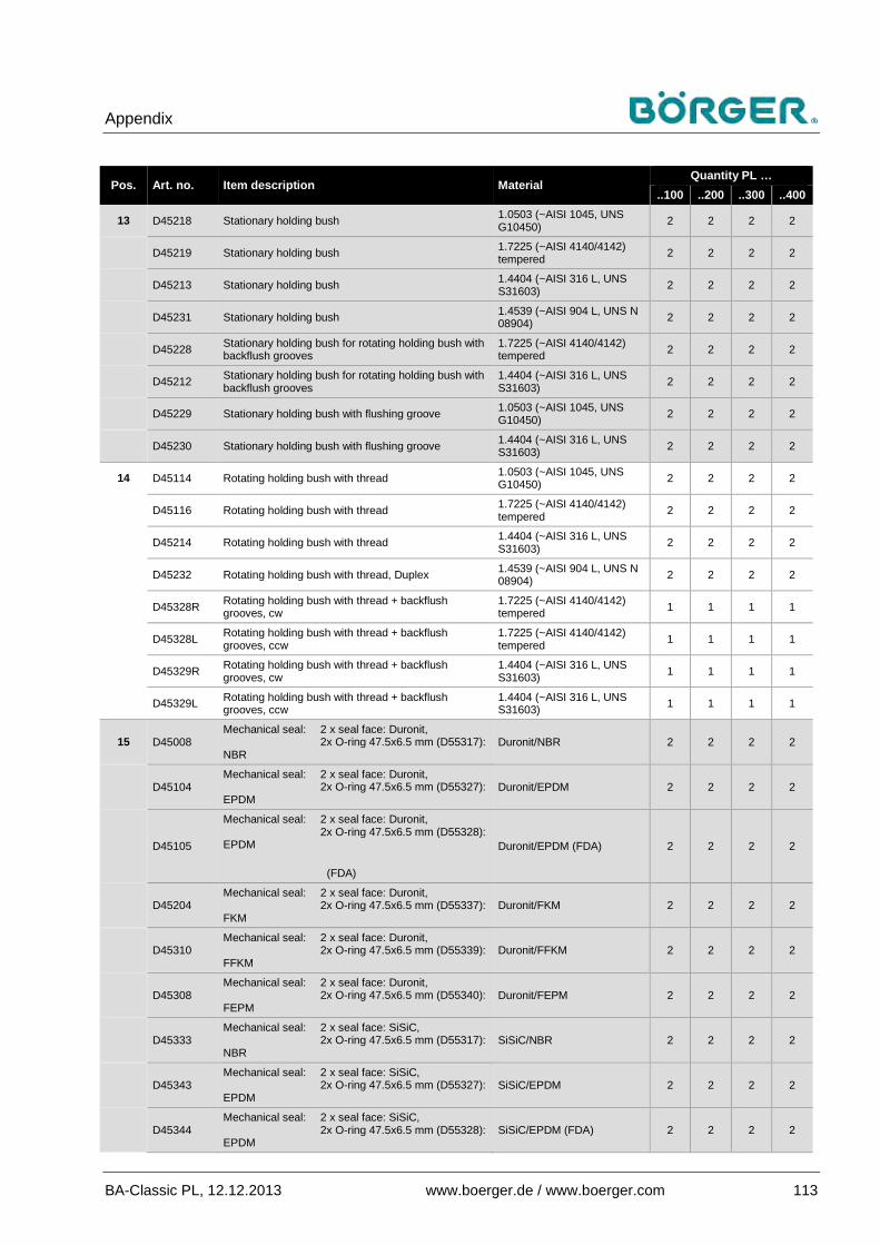
Appendix
BA-Classic PL, 12.12.2013 www.boerger.de / www.boerger.com 113
Pos. Art. no. Item description Material Quantity PL …
..100 ..200 ..300 ..400
13 D45218 Stationary holding bush 1.0503 (~AISI 1045, UNS G10450) 2 2 2 2
D45219 Stationary holding bush 1.7225 (~AISI 4140/4142) tempered 2 2 2 2
D45213 Stationary holding bush 1.4404 (~AISI 316 L, UNS S31603) 2 2 2 2
D45231 Stationary holding bush 1.4539 (~AISI 904 L, UNS N 08904) 2 2 2 2
D45228 Stationary holding bush for rotating holding bush with backflush grooves
1.7225 (~AISI 4140/4142) tempered 2 2 2 2
D45212 Stationary holding bush for rotating holding bush with backflush grooves
1.4404 (~AISI 316 L, UNS S31603) 2 2 2 2
D45229 Stationary holding bush with flushing groove 1.0503 (~AISI 1045, UNS G10450) 2 2 2 2
D45230 Stationary holding bush with flushing groove 1.4404 (~AISI 316 L, UNS S31603) 2 2 2 2
14 D45114 Rotating holding bush with thread 1.0503 (~AISI 1045, UNS G10450) 2 2 2 2
D45116 Rotating holding bush with thread 1.7225 (~AISI 4140/4142) tempered 2 2 2 2
D45214 Rotating holding bush with thread 1.4404 (~AISI 316 L, UNS S31603) 2 2 2 2
D45232 Rotating holding bush with thread, Duplex 1.4539 (~AISI 904 L, UNS N 08904) 2 2 2 2
D45328R Rotating holding bush with thread + backflush grooves, cw
1.7225 (~AISI 4140/4142) tempered 1 1 1 1
D45328L Rotating holding bush with thread + backflush grooves, ccw
1.7225 (~AISI 4140/4142) tempered 1 1 1 1
D45329R Rotating holding bush with thread + backflush grooves, cw
1.4404 (~AISI 316 L, UNS S31603) 1 1 1 1
D45329L Rotating holding bush with thread + backflush grooves, ccw
1.4404 (~AISI 316 L, UNS S31603) 1 1 1 1
15 D45008 Mechanical seal: 2 x seal face: Duronit, 2x O-ring 47.5x6.5 mm (D55317): NBR
Duronit/NBR 2 2 2 2
D45104 Mechanical seal: 2 x seal face: Duronit, 2x O-ring 47.5x6.5 mm (D55327): EPDM
Duronit/EPDM 2 2 2 2
D45105
Mechanical seal: 2 x seal face: Duronit, 2x O-ring 47.5x6.5 mm (D55328): EPDM (FDA)
Duronit/EPDM (FDA) 2 2 2 2
D45204 Mechanical seal: 2 x seal face: Duronit, 2x O-ring 47.5x6.5 mm (D55337): FKM
Duronit/FKM 2 2 2 2
D45310 Mechanical seal: 2 x seal face: Duronit, 2x O-ring 47.5x6.5 mm (D55339): FFKM
Duronit/FFKM 2 2 2 2
D45308 Mechanical seal: 2 x seal face: Duronit, 2x O-ring 47.5x6.5 mm (D55340): FEPM
Duronit/FEPM 2 2 2 2
D45333 Mechanical seal: 2 x seal face: SiSiC, 2x O-ring 47.5x6.5 mm (D55317): NBR
SiSiC/NBR 2 2 2 2
D45343 Mechanical seal: 2 x seal face: SiSiC, 2x O-ring 47.5x6.5 mm (D55327): EPDM
SiSiC/EPDM 2 2 2 2
D45344 Mechanical seal: 2 x seal face: SiSiC, 2x O-ring 47.5x6.5 mm (D55328): EPDM
SiSiC/EPDM (FDA) 2 2 2 2
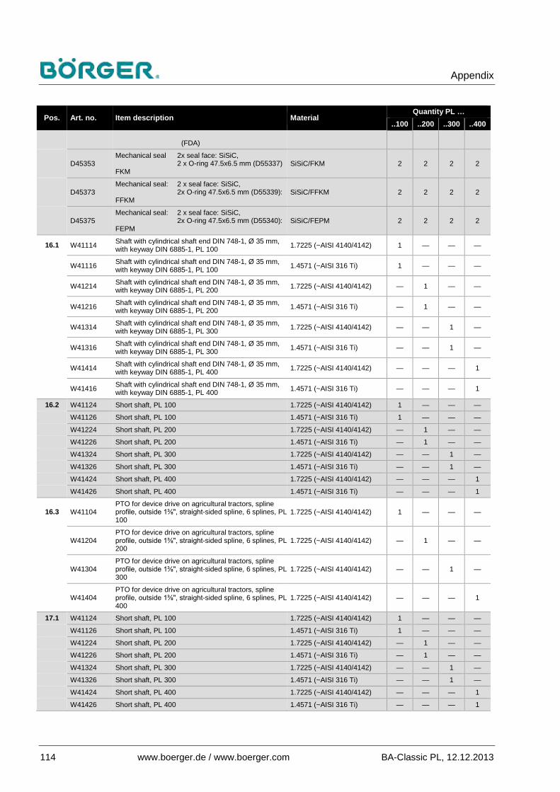
Appendix
114 www.boerger.de / www.boerger.com BA-Classic PL, 12.12.2013
Pos. Art. no. Item description Material Quantity PL …
..100 ..200 ..300 ..400 (FDA)
D45353 Mechanical seal 2x seal face: SiSiC, 2 x O-ring 47.5x6.5 mm (D55337) FKM
SiSiC/FKM 2 2 2 2
D45373 Mechanical seal: 2 x seal face: SiSiC, 2x O-ring 47.5x6.5 mm (D55339): FFKM
SiSiC/FFKM 2 2 2 2
D45375 Mechanical seal: 2 x seal face: SiSiC, 2x O-ring 47.5x6.5 mm (D55340): FEPM
SiSiC/FEPM 2 2 2 2
16.1 W41114 Shaft with cylindrical shaft end DIN 748-1, Ø 35 mm, with keyway DIN 6885-1, PL 100 1.7225 (~AISI 4140/4142) 1 — — —
W41116 Shaft with cylindrical shaft end DIN 748-1, Ø 35 mm, with keyway DIN 6885-1, PL 100 1.4571 (~AISI 316 Ti) 1 — — —
W41214 Shaft with cylindrical shaft end DIN 748-1, Ø 35 mm, with keyway DIN 6885-1, PL 200 1.7225 (~AISI 4140/4142) — 1 — —
W41216 Shaft with cylindrical shaft end DIN 748-1, Ø 35 mm, with keyway DIN 6885-1, PL 200 1.4571 (~AISI 316 Ti) — 1 — —
W41314 Shaft with cylindrical shaft end DIN 748-1, Ø 35 mm, with keyway DIN 6885-1, PL 300 1.7225 (~AISI 4140/4142) — — 1 —
W41316 Shaft with cylindrical shaft end DIN 748-1, Ø 35 mm, with keyway DIN 6885-1, PL 300 1.4571 (~AISI 316 Ti) — — 1 —
W41414 Shaft with cylindrical shaft end DIN 748-1, Ø 35 mm, with keyway DIN 6885-1, PL 400 1.7225 (~AISI 4140/4142) — — — 1
W41416 Shaft with cylindrical shaft end DIN 748-1, Ø 35 mm, with keyway DIN 6885-1, PL 400 1.4571 (~AISI 316 Ti) — — — 1
16.2 W41124 Short shaft, PL 100 1.7225 (~AISI 4140/4142) 1 — — —
W41126 Short shaft, PL 100 1.4571 (~AISI 316 Ti) 1 — — —
W41224 Short shaft, PL 200 1.7225 (~AISI 4140/4142) — 1 — —
W41226 Short shaft, PL 200 1.4571 (~AISI 316 Ti) — 1 — —
W41324 Short shaft, PL 300 1.7225 (~AISI 4140/4142) — — 1 —
W41326 Short shaft, PL 300 1.4571 (~AISI 316 Ti) — — 1 —
W41424 Short shaft, PL 400 1.7225 (~AISI 4140/4142) — — — 1
W41426 Short shaft, PL 400 1.4571 (~AISI 316 Ti) — — — 1
16.3 W41104 PTO for device drive on agricultural tractors, spline profile, outside 1⅜", straight-sided spline, 6 splines, PL 100
1.7225 (~AISI 4140/4142) 1 — — —
W41204 PTO for device drive on agricultural tractors, spline profile, outside 1⅜", straight-sided spline, 6 splines, PL 200
1.7225 (~AISI 4140/4142) — 1 — —
W41304 PTO for device drive on agricultural tractors, spline profile, outside 1⅜", straight-sided spline, 6 splines, PL 300
1.7225 (~AISI 4140/4142) — — 1 —
W41404 PTO for device drive on agricultural tractors, spline profile, outside 1⅜", straight-sided spline, 6 splines, PL 400
1.7225 (~AISI 4140/4142) — — — 1
17.1 W41124 Short shaft, PL 100 1.7225 (~AISI 4140/4142) 1 — — —
W41126 Short shaft, PL 100 1.4571 (~AISI 316 Ti) 1 — — —
W41224 Short shaft, PL 200 1.7225 (~AISI 4140/4142) — 1 — —
W41226 Short shaft, PL 200 1.4571 (~AISI 316 Ti) — 1 — —
W41324 Short shaft, PL 300 1.7225 (~AISI 4140/4142) — — 1 —
W41326 Short shaft, PL 300 1.4571 (~AISI 316 Ti) — — 1 —
W41424 Short shaft, PL 400 1.7225 (~AISI 4140/4142) — — — 1
W41426 Short shaft, PL 400 1.4571 (~AISI 316 Ti) — — — 1

Appendix
BA-Classic PL, 12.12.2013 www.boerger.de / www.boerger.com 115
Pos. Art. no. Item description Material Quantity PL …
..100 ..200 ..300 ..400
17.2 W41114 Shaft with cylindrical shaft end DIN 748-1, Ø 35 mm, with keyway DIN 6885-1, PL 100 1.7225 (~AISI 4140/4142) 1 — — —
W41116 Shaft with cylindrical shaft end DIN 748-1, Ø 35 mm, with keyway DIN 6885-1, PL 100 1.4571 (~AISI 316 Ti) 1 — — —
W41214 Shaft with cylindrical shaft end DIN 748-1, Ø 35 mm, with keyway DIN 6885-1, PL 200 1.7225 (~AISI 4140/4142) — 1 — —
W41216 Shaft with cylindrical shaft end DIN 748-1, Ø 35 mm, with keyway DIN 6885-1, PL 200 1.4571 (~AISI 316 Ti) — 1 — —
W41314 Shaft with cylindrical shaft end DIN 748-1, Ø 35 mm, with keyway DIN 6885-1, PL 300 1.7225 (~AISI 4140/4142) — — 1 —
W41316 Shaft with cylindrical shaft end DIN 748-1, Ø 35 mm, with keyway DIN 6885-1, PL 300 1.4571 (~AISI 316 Ti) — — 1 —
W41414 Shaft with cylindrical shaft end DIN 748-1, Ø 35 mm, with keyway DIN 6885-1, PL 400 1.7225 (~AISI 4140/4142) — — — 1
W41416 Shaft with cylindrical shaft end DIN 748-1, Ø 35 mm, with keyway DIN 6885-1, PL 400 1.4571 (~AISI 316 Ti) — — — 1
17.3 W41104 PTO for device drive on agricultural tractors, spline profile, outside 1⅜", straight-sided spline, 6 splines, PL 100
1.7225 (~AISI 4140/4142) 1 — — —
W41204 PTO for device drive on agricultural tractors, spline profile, outside 1⅜", straight-sided spline, 6 splines, PL 200
1.7225 (~AISI 4140/4142) — 1 — —
W41304 PTO for device drive on agricultural tractors, spline profile, outside 1⅜", straight-sided spline, 6 splines, PL 300
1.7225 (~AISI 4140/4142) — — 1 —
W41404 PTO for device drive on agricultural tractors, spline profile, outside 1⅜", straight-sided spline, 6 splines, PL 400
1.7225 (~AISI 4140/4142) — — — 1
19.a E12111 Gear wheel with keyway, center tooth 1.7225 (~AISI 4140/4142) 1 1 1 1
19.b E12110 Gear wheel with keyway, center tooth space 1.7225 (~AISI 4140/4142) 1 1 1 1
24 C80004 Cover disk for rotors made from steel / stainless steel 1.7225 (~AISI 4140/4142) 2 2 2 2
C80104 Cover disk for rotors made from steel / stainless steel 1.4571 (~AISI 316 Ti) 2 2 2 2
C80108 Cover disk for rotors made from steel / stainless steel 1.4539 (~AISI 904 L, UNS N 08904) 2 2 2 2
25.1 O45760 Flange seal, O-ring 110x3.5, PL 100 NBR 2 — — —
O45761 Flange seal, O-ring 110x3.5, PL 100 EPDM 2 — — —
O45762 Flange seal, O-ring 110x3.5, PL 100 FKM 2 — — —
O45770 Flange seal, O-ring 139x3.5, PL 200 NBR — 2 — —
O45771 Flange seal, O-ring 139x3.5, PL 200 EPDM — 2 — —
O45772 Flange seal, O-ring 139x3.5, PL 200 FKM — 2 — —
O45780 Flange seal, O-ring 174x3.5, PL 300 NBR — — 2 —
O45781 Flange seal, O-ring 174x3.5, PL 300 EPDM — — 2 —
O45782 Flange seal, O-ring 174x3.5, PL 300 FKM — — 2 —
O45790 Flange seal, O-ring 209x3.5, PL 400 NBR — — — 2
O45791 Flange seal, O-ring 209x3.5, PL 400 EPDM — — — 2
O45792 Flange seal, O-ring 209x3.5, PL 400 FKM — — — 2
25.2 F82018 Flange seal, gasket 2 mm, PL 100 NBR 2 — — —
F82134 Flange seal, gasket 2 mm, PL 100 EPDM 2 — — —
F82144 Flange seal, gasket 2 mm, PL 100 FKM 2 — — —
F82057 Flange seal, gasket 2 mm, PL 100 PTFE base 2 — — —
F82028 Flange seal, gasket 2 mm, PL 200 NBR — 2 — —
F82234 Flange seal, gasket 2 mm, PL 200 EPDM — 2 — —
F82244 Flange seal, gasket 2 mm, PL 200 FKM — 2 — —
F82067 Flange seal, gasket 2 mm, PL 200 PTFE base — 2 — —

Appendix
116 www.boerger.de / www.boerger.com BA-Classic PL, 12.12.2013
Pos. Art. no. Item description Material Quantity PL …
..100 ..200 ..300 ..400 F82038 Flange seal, gasket 2 mm, PL 300 NBR — — 2 —
F82334 Flange seal, gasket 2 mm, PL 300 EPDM — — 2 —
F82344 Flange seal, gasket 2 mm, PL 300 FKM — — 2 —
F82077 Flange seal, gasket 2 mm, PL 300 PTFE base — — 2 —
F82048 Flange seal, gasket 2 mm, PL 400 NBR — — — 2
F82434 Flange seal, gasket 2 mm, PL 400 EPDM — — — 2
F82444 Flange seal, gasket 2 mm, PL 400 FKM — — — 2
30 O45408 O-ring for cover, 250x7 mm NBR 1 1 1 1
O45424 O-ring for cover, 250x7 mm EPDM 1 1 1 1
O45418 O-ring for cover, 250x7 mm FKM 1 1 1 1
O45438 O-ring for cover, 248x6.5 mm FEP/FKM 1 1 1 1
O45426 O-ring for cover, 250x7 mm CSM 1 1 1 1
31 O45508 O-ring for rotating holding bush, 54x4 mm NBR 2 2 2 2
O45524 O-ring for rotating holding bush, 54x4 mm EPDM 2 2 2 2
O45518 O-ring for rotating holding bush, 54x4 mm FKM 2 2 2 2
O45545 O-ring for rotating holding bush, 54x4 mm FEPM 2 2 2 2
O45537 O-ring for rotating holding bush, 54x4 mm FEP/FKM 2 2 2 2
O45540 O-ring for rotating holding bush, 54x4 mm FFKM 2 2 2 2
O45550 O-ring for rotating holding bush, 54x4 mm CSM 2 2 2 2
32 O45508 O-ring for cover disk, 54x4 mm NBR 0/2 0/2 0/2 0/2
O45524 O-ring for cover disk, 54x4 mm EPDM 0/2 0/2 0/2 0/2
O45518 O-ring for cover disk, 54x4 mm FKM 0/2 0/2 0/2 0/2
O45545 O-ring for cover disk, 54x4 mm FEPM 0/2 0/2 0/2 0/2
O45537 O-ring for cover disk, 54x4 mm FEP/FKM 0/2 0/2 0/2 0/2
O45540 O-ring for cover disk, 54x4 mm FFKM 0/2 0/2 0/2 0/2
33 O45708 O-ring for stationary holding bush, 80x3 mm NBR 2 2 2 2
O45724 O-ring for stationary holding bush, 80x3 mm EPDM 2 2 2 2
O45718 O-ring for stationary holding bush, 80x3 mm FKM 2 2 2 2
O45745 O-ring for stationary holding bush, 80x3 mm FEPM 2 2 2 2
O45737 O-ring for stationary holding bush, 80x3 mm FEP/FKM 2 2 2 2
O45740 O-ring for stationary holding bush, 80x3 mm FFKM 2 2 2 2
36 S16508 Lip seal with dust protection lip, DIN 3760 form AS, 45x70x10 mm NBR 1/2 1/2 1/2 1/2
S16509 Lip seal with dust protection lip, DIN 3760 form AS, 45x70x10 mm FKM 1/2 1/2 1/2 1/2
37 S16108 DUO double lip seal, 55x80x10 mm NBR 2 2 2 2
S16118 DUO double lip seal, 55x80x10 mm FKM 2 2 2 2
40 S14608 Cylindrical roller bearing, NJ2309, DIN 5412 Cage 1.3505 (~AISI 52100) 2 2 2 2
S14618 Cylindrical roller bearing (extra long life) NJ2309, DIN 5412 / ISO 281 Cage 1.3505 (~AISI 52100) 2 2 2 2
41 S14508 Self-aligning roller bearing, 22310, DIN 635 Cage 1.3505 (~AISI 52100) 2 2 2 2
S14518 Self-aligning roller bearing (extra long life), 22310, DIN 635 / ISO 281 Cage 1.3505 (~AISI 52100) 2 2 2 2
42 S16229 Inner ring as shaft protection sleeve, 50x55x25 mm 1.3505 (~AISI 52100) hardened 2 2 2 2
S16452 Inner ring as shaft protection sleeve, 50x55x25 mm 1.4034 (~AISI 420 C) hardened 2 2 2 2
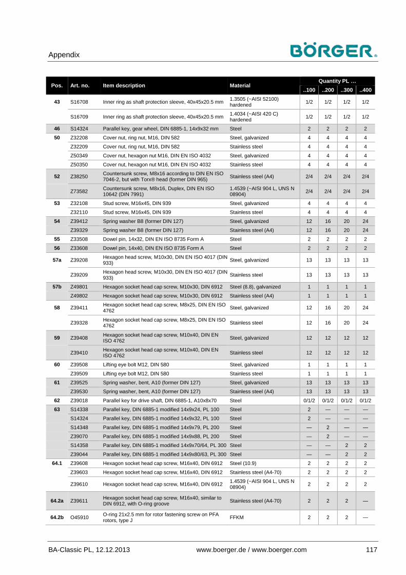
Appendix
BA-Classic PL, 12.12.2013 www.boerger.de / www.boerger.com 117
Pos. Art. no. Item description Material Quantity PL …
..100 ..200 ..300 ..400
43 S16708 Inner ring as shaft protection sleeve, 40x45x20.5 mm 1.3505 (~AISI 52100) hardened 1/2 1/2 1/2 1/2
S16709 Inner ring as shaft protection sleeve, 40x45x20.5 mm 1.4034 (~AISI 420 C) hardened 1/2 1/2 1/2 1/2
46 S14324 Parallel key, gear wheel, DIN 6885-1, 14x9x32 mm Steel 2 2 2 2
50 Z32208 Cover nut, ring nut, M16, DIN 582 Steel, galvanized 4 4 4 4
Z32209 Cover nut, ring nut, M16, DIN 582 Stainless steel 4 4 4 4
Z50349 Cover nut, hexagon nut M16, DIN EN ISO 4032 Steel, galvanized 4 4 4 4
Z50350 Cover nut, hexagon nut M16, DIN EN ISO 4032 Stainless steel 4 4 4 4
52 Z38250 Countersunk screw, M8x16 according to DIN EN ISO 7046-2, but with Torx® head (former DIN 965) Stainless steel (A4) 2/4 2/4 2/4 2/4
Z73582 Countersunk screw, M8x16, Duplex, DIN EN ISO 10642 (DIN 7991)
1.4539 (~AISI 904 L, UNS N 08904) 2/4 2/4 2/4 2/4
53 Z32108 Stud screw, M16x45, DIN 939 Steel, galvanized 4 4 4 4
Z32110 Stud screw, M16x45, DIN 939 Stainless steel 4 4 4 4
54 Z39412 Spring washer B8 (former DIN 127) Steel, galvanized 12 16 20 24
Z39329 Spring washer B8 (former DIN 127) Stainless steel (A4) 12 16 20 24
55 Z33508 Dowel pin, 14x32, DIN EN ISO 8735 Form A Steel 2 2 2 2
56 Z33608 Dowel pin, 14x40, DIN EN ISO 8735 Form A Steel 2 2 2 2
57a Z39208 Hexagon head screw, M10x30, DIN EN ISO 4017 (DIN 933) Steel, galvanized 13 13 13 13
Z39209 Hexagon head screw, M10x30, DIN EN ISO 4017 (DIN 933) Stainless steel 13 13 13 13
57b Z49801 Hexagon socket head cap screw, M10x30, DIN 6912 Steel (8.8), galvanized 1 1 1 1
Z49802 Hexagon socket head cap screw, M10x30, DIN 6912 Stainless steel (A4) 1 1 1 1
58 Z39411 Hexagon socket head cap screw, M8x25, DIN EN ISO 4762 Steel, galvanized 12 16 20 24
Z39328 Hexagon socket head cap screw, M8x25, DIN EN ISO 4762 Stainless steel 12 16 20 24
59 Z39408 Hexagon socket head cap screw, M10x40, DIN EN ISO 4762 Steel, galvanized 12 12 12 12
Z39410 Hexagon socket head cap screw, M10x40, DIN EN ISO 4762 Stainless steel 12 12 12 12
60 Z39508 Lifting eye bolt M12, DIN 580 Steel, galvanized 1 1 1 1
Z39509 Lifting eye bolt M12, DIN 580 Stainless steel 1 1 1 1
61 Z39525 Spring washer, bent, A10 (former DIN 127) Steel, galvanized 13 13 13 13
Z39530 Spring washer, bent, A10 (former DIN 127) Stainless steel (A4) 13 13 13 13
62 Z39018 Parallel key for drive shaft, DIN 6885-1, A10x8x70 Steel 0/1/2 0/1/2 0/1/2 0/1/2
63 S14338 Parallel key, DIN 6885-1 modified 14x9x24, PL 100 Steel 2 — — —
S14324 Parallel key, DIN 6885-1 modified 14x9x32, PL 100 Steel 2 — — —
S14348 Parallel key, DIN 6885-1 modified 14x9x79, PL 200 Steel — 2 — —
Z39070 Parallel key, DIN 6885-1 modified 14x9x88, PL 200 Steel — 2 — —
S14358 Parallel key, DIN 6885-1 modified 14x9x70/64, PL 300 Steel — — 2 2
Z39044 Parallel key, DIN 6885-1 modified 14x9x80/63, PL 300 Steel — — 2 2
64.1 Z39608 Hexagon socket head cap screw, M16x40, DIN 6912 Steel (10.9) 2 2 2 2
Z39603 Hexagon socket head cap screw, M16x40, DIN 6912 Stainless steel (A4-70) 2 2 2 2
Z39610 Hexagon socket head cap screw, M16x40, DIN 6912 1.4539 (~AISI 904 L, UNS N 08904) 2 2 2 2
64.2a Z39611 Hexagon socket head cap screw, M16x40, similar to DIN 6912, with O-ring groove Stainless steel (A4-70) 2 2 2 —
64.2b O45910 O-ring 21x2.5 mm for rotor fastening screw on PFA rotors, type J FFKM 2 2 2 —

Appendix
118 www.boerger.de / www.boerger.com BA-Classic PL, 12.12.2013
Pos. Art. no. Item description Material Quantity PL …
..100 ..200 ..300 ..400 65 Z18508 Oil sight glass, G 1 A (1" BSPP male) Brass 1 1 1 1
Z18509 Oil sight glass, G 1 A (1" BSPP male) Stainless steel 1 1 1 1
66 Z19308 Screw plug, G ½ A (½" BSPP male), for oil drain, DIN 908 Steel, galvanized 2 2 2 2
Z19310 Screw plug, G ½ A (½" BSPP male), for oil drain, DIN 908 Stainless steel 2 2 2 2
67 Z19108 Breather, G ½ A (½" BSPP male) Steel, galvanized 1 1 1 1
Z18408 Oil sight glass, G ½ A (½" BSPP male) (for 90° turned pumps) Brass 1 1 1 1
68 Z41150 Grub screw, M8x12, EN ISO4027 Steel, galvanized 4 4 4 4
69 Z29305 Screw plug, G ⅜" (⅜" BSPP male), DIN 908 Steel, galvanized 1 1 1 1
70 K22108 Sealing washer, A33x39x2 (for screw plug, position 78) Cu 1 1 1 1
71 K22408 Sealing washer, A21x26X1.5 (for position 66) Cu 2 2 2 2
72 K22208 Sealing washer, A33x39x1.5 (for position 65) Cellulose/NBR 1 1 1 1
73 K22210 Sealing washer 21x26x1.5 for oil sight glass ½" on 90° turned pump Cellulose/NBR 0/1 0/1 0/1 0/1
74 K32405 Sealing washer, A17x23x1.5 Cu 0/2 0/2 0/2 0/2
K34003 Sealing washer, A16x25x1.6 PTFE 0/2 0/2 0/2 0/2
75 MECH-3025 Breather G ⅜" (⅜" BSPP), male Aluminum, anodized bright 1 1 1 1
77 K23008 Snap ring, J 110, DIN 472 Steel 2 2 2 2
78 Z22815 Screw plug for gear unit, G 1 A (1" BSPP male), DIN 908 Steel, galvanized 1 1 1 1
Z22820 Screw plug for gear unit, G 1 A (1" BSPP male), DIN 908 Stainless steel 1 1 1 1
79 K32405 Sealing washer A17x23x1.5, DIN 7603, for pos. 69 and 80 Cu 2 2 2 2
80 Z29305 Screw plug, G ⅜" (⅜" BSPP male), DIN 908 Steel, galvanized 1 1 1 1
Pos. Art. no. Tool / installation aid Material Quantity PL …
..100 ..200 ..300 ..400 W1 U22308 Sealing compound (50 ml tube) 1 1 1 1
U22208 Sealing compound (200 ml tube) 1 1 1 1
W2 U22918 Rotor puller 1.0038 (~ASTM A570-36) 1 1 1 1
W3.1 U22930 Auxiliary puller for dual-lobe rotors made from steel / stainless steel (Premium, Optimum) * 1.0038 (~ASTM A570-36) 0 / 1 0 / 1 0 / 1 0 / 1
W3.2 U22958 Auxiliary puller for rear rotors, types A and D, for PL 400 ** 1.0038 (~ASTM A570-36) — — — 0 / 1
W4 U22102 Multitool, push-in tool for mechanical seal and special tool for rotating holding bush 1.0038 (~ASTM A570-36) 1 1 1 1
*to be used with two M12x30 screws or, for rear rotors (Premium, Optimum made from steel / stainless steel) on PL 400, with two M12x140 threaded rods with M12 nuts as a head (as a stop for the auxiliary puller) **to be used with three M6x130 threaded rods with M6 nuts as a head (as a stop for the auxiliary puller)
There is a wide variety of attachment parts, such as the coupling guard and pipe connectors, which are delivered depending on the order. This means that not all variations can be listed here. Always quote the Börger order number or pump number according to the nameplate when ordering spare parts.

Appendix
BA-Classic PL, 12.12.2013 www.boerger.de / www.boerger.com 119
Material information on spare parts list Material Description ~ Equivalent
US market
EN-JL1040 Gray cast iron (EN-GJL-250), DIN EN 1561 (former designation GG 25 / 0.6025)
ASTM A48-40 B, UNS F12801
EN-JS1030 Spheroidal graphite cast iron (EN-GJS-400-15), DIN EN 1563 (Sphäroguss®; former designation GGG 40 / 0.7040)
ASTM A536, 60-40-18, UNS F32800
EN-JS1060 Spheroidal graphite cast iron (EN-GJS-600-3), DIN EN 1563 (Sphäroguss®; former designation GGG 60 / 0.7060)
A48-45 B, ASTM A536 80-55-06, UNS F33800
1.0038 Non-alloy structural steel, hot rolled, DIN EN 10025-2 (former designation St 37) ASTM A570-36
1.0503 Non-alloy steel for quenching and tempering as per DIN EN 10083-2 (former designation C45)
AISI 1045, UNS G10450
1.2379 Secondary hardening, 12% Cr cold work tool steel AISI D2 1.3505 Ball and roller bearing steel (100Cr6), DIN EN ISO 683-17 AISI 52100 1.4034 Martensitic stainless steel (X5CrNi18-10), DIN EN 10088 AISI 420 C 1.4301 Austenitic stainless steel, DIN EN 10088, (V2A) AISI 304
1.4404 Austenitic stainless steel (X2CrNiMo17-12-2), DIN EN 10088 AISI 316 L, UNS S31603
1.4462 Austenitic-ferritic duplex steel (X2CrNiMON22-5-3), DIN EN 10088 ASTM A182 F-51 318LN, UNS S 31803
1.4517 Corrosion-resistant austenitic-ferritic steel casting (GX2CrNiMoCuN25-6-3-3), DIN EN 10283 (Duplex) ASTM A 890
1.4539 Superaustenitic stainless steel (X1NiCrMoCu25-20-5), DIN EN 10088, (A5) AISI 904 L, UNS N 08904
1.4571 Austenitic stainless steel (X6CrNiMoTi17-12-2), DIN EN 10088, (V4A) AISI 316 Ti
1.6220 Steel casting for pressure purposes with specified low temperature properties, G20Mn5 V, DIN EN 10213, (formerly 1.1120, GS2 20 Mn5, DIN 17182)
Steel casting, ~ ASTM A352 LCB
1.7218 Alloy steel for quenching and tempering (25CrMo4), DIN EN 10083-3 AISI 4130 1.7225 Alloy steel for quenching and tempering (42CrMo4V), DIN EN 10083-3 AISI 4140/4142
1.8714 Hard metal (non-wearing special structural steel, trade names: Hardox ®, XAR® 400) —
CSM Chlorine-sulphonyl-polyethylene rubber CSM Duronit ® Ledeburitic chilled cast iron (60-65 HRC) Duronit ®
EPDM Ethylene-propylene-diene rubber (trade marks e.g. Vistalon® Keltan®) EPDM
FEPM Tetrafluorine-ethylene-propylene rubber (trade marks e.g. Aflas®, Viton extreme®) FEPM
FFKM Perfluoro rubber (previously FFPM; trade marks e.g. Chemraz®, Kalrez®) FFKM FKM Fluoro rubber (previously FPM; trade mark e.g. Viton®) FKM
HNBR Hydrogenated acrylonitrile-butadiene rubber (trade marks e.g. Therban®, Zetpol®) HNBR
HPM™ Bearing material made of PTFE, reinforced with full-length, high-strength coiled fibers, encapsulated in high-strength epoxy resin HPMTM
NBR Acrylonitrile-butadiene rubber (trade mark e.g. Buna N®) NBR NR Natural rubber NR PE Polyethylene PE PFA Perfluoroalkoxy (trade marks e.g. Teflon®, Symalit®, Hyflon®) PFA PTFE Polytetrafluoroethylene (trade mark e.g. Teflon®) PTFE PU / PUR Polyurethane PU / PUR
SBR Styrene-butadiene rubber (trade marks e.g. Buna S®, Solprene®) SBR
SiSiC Reaction-bonded, silicium-infiltrated silicon carbide with extreme abrasion resistance SiSiC
TC Tungsten carbide (normally bonded e.g. with 6% nickel = TC-6N) TC

Appendix
120 www.boerger.de / www.boerger.com BA-Classic PL, 12.12.2013
Type code table 9.5The following type code table can be used to identify your pump version.
Observe the additional descriptions in the delivery note, invoice or data sheet for special variations that are not included in the type code.
The letter X at any position of the type code indicates that your pump is equipped with a special part at this position, for instance a part made from a different material than those listed in our regular type code.
To facilitate the quick and accurate ordering of spare parts, record the necessary details and all modifications to the pump equipment in the space provided at the end of the type code table. Always indicate any modifications explicitly on every spare part order.

Appendix
BA-Classic PL, 12.12.2013 www.boerger.de / www.boerger.com 121
Type code
1 Eq
uipm
ent g
roup
2 Ty
pe
3 Si
ze
4 G
ear d
esig
n
5 D
rive
shaf
ts
6 Fl
ow d
irect
ion
7 Li
p se
als,
inne
r rin
gs
8 C
asin
g
9 C
asin
g pr
otec
tion
plat
es
10 C
asin
g lin
ers
11 H
oldi
ng b
ushe
s
12 M
echa
nica
l sea
ls
13 R
otor
s / b
lade
s
14 R
otor
/ bl
ade
mat
eria
l
15 O
-rin
gs
16 F
lang
e se
als
17 M
ount
ing
posi
tion
18 S
erie
s in
dex
19 S
peci
al e
quip
men
t
1-3 Pump type Classic AL 25 P A 2 4 Classic AL 50 P A 5 4 Classic AL 75 P A 7 4 Classic / Select PL 100 P P 1 5 Classic / Select PL 200 P P 2 5 Classic / Select PL 300 P P 3 5 Classic / Select PL 400 P P 4 5 Classic / Select CL 260 P C 2 5 Classic / Select CL 390 P C 3 5 Classic / Select CL 520 P C 5 5 Classic / Select FL 518 P F 5 4 Classic / Select FL 776 P F 7 4 Classic / Select FL 1036 P F 1 4 Classic FLA 518 P L 5 4 Classic FLA 776 P L 7 4 Classic FLA 1036 P L 1 4 Classic FLA 1540 P L 4 4 Classic FLA 2072 P L 2 4 Classic EL 1000 P E 0 1 Classic EL 1550 P E 1 1 Classic EL 2250 P E 2 1 Classic EL 3050 P E 3 1 Classic XL 1760 P X 1 1 Classic XL 2650 P X 2 1 Classic XL 3530 P X 3 1 Protect PL 100 P D 1 1 Protect PL 200 P D 2 1 Protect PL 300 P D 3 1 Protect PL 400 P D 4 1 Protect FL 518 P G 5 1 Protect FL 776 P G 7 1 Protect FL 1036 P G 1 1
4 Gear design (bearing) Standard S ATEX A Reinforced bearing V
5 Drive shafts (design, position, material) 1x drive shaft, cylindrical with keyway, pos. 0, steel A 1x drive shaft, cylindrical with keyway, pos. 1, steel B 2x drive shaft, cylindrical with keyway, pos. 0 and 1, steel C 2x drive shaft with PTO profile 1⅜", 6 tooth, pos. 0 and 1, steel D 1x drive shaft with PTO profile 1⅜", 6 tooth, pos. 0, steel E 1x drive shaft with PTO profile 1⅜", 6 tooth, pos. 1, steel F 2x drive shaft with PTO profile 1¾", 20 tooth, pos. 0 and 1, steel G 1x drive shaft with PTO profile 1¾", 20 tooth, pos. 0, steel H 1x drive shaft with PTO profile 1¾", 20 tooth, pos. 1, steel I 1x hollow drive shaft, cylindrical with parallel key, pos. 0, steel J 1x hollow drive shaft, cylindrical with parallel key, pos. 1, steel K 1x hollow drive shaft with PTO profile 1⅜", 6 tooth, pos. 0, steel L 1x hollow drive shaft with PTO profile 1⅜", 6 tooth, pos. 1, steel M 1x drive shaft, cylindrical with keyway, pos. 0, stainless steel N 1x drive shaft, cylindrical with keyway, pos. 1, stainless steel O 2x drive shaft with PTO profile 1¾", 6 tooth, pos. 0 and 1, steel P 1x drive shaft with PTO profile 1¾", 6 tooth, pos. 0, steel Q 1x drive shaft with PTO profile 1¾", 6 tooth, pos. 1, steel R

Appendix
122 www.boerger.de / www.boerger.com BA-Classic PL, 12.12.2013
Type code
1 Eq
uipm
ent g
roup
2 Ty
pe
3 Si
ze
4 G
ear d
esig
n
5 D
rive
shaf
ts
6 Fl
ow d
irect
ion
7 Li
p se
als,
inne
r rin
gs
8 C
asin
g
9 C
asin
g pr
otec
tion
plat
es
10 C
asin
g lin
ers
11 H
oldi
ng b
ushe
s
12 M
echa
nica
l sea
ls
13 R
otor
s / b
lade
s
14 R
otor
/ bl
ade
mat
eria
l
15 O
-rin
gs
16 F
lang
e se
als
17 M
ount
ing
posi
tion
18 S
erie
s in
dex
19 S
peci
al e
quip
men
t
1x drive shaft with spline profile according to former DIN 5482, pos. 0, steel S
1x drive shaft with spline profile according to former DIN 5482, pos. 1, steel T
6 Flow direction From left to right (when looking at the quick-release cover) A From right to left (when looking at the quick-release cover) B Reversible R
7 Lip seals, inner rings Classic NBR / steel C Classic FKM / steel I Classic NBR / stainless steel E Classic FKM / stainless steel J Classic magnet-activated bearing isolator M Classic PTFE / steel P Select NBR / steel R Select FKM / steel S Select PTFE / steel T
8 Pump casing Gray cast iron, standard A Gray cast iron, nitrite hardened B Spheroidal cast iron, laser hardened C Stainless steel D Stainless steel, plasma hardened E Gray cast iron, with radial MIP liners F Gray cast iron, with radial MIP liners I Special steel casting J Special steel casting, with radial MIP liners K Gray cast iron, standard, Select N Stainless steel, Select O Gray cast iron, with radial MIP liners, Select R Stainless steel, with radial MIP liners, Select S
9 Casing protection plates Hard metal A Stainless steel B Hard metal, with fiber barrier edge C Stainless steel, 1.4539 I Hard metal (special version for fiber barrier) D Stainless steel (special version for fiber barrier) E Ceramic F Ceramic coated G Stainless steel, plasma hardened H Longlife ceramic composite K
10 Casing liners Hard metal A Stainless steel B Stainless steel, 1.4539 C Ceramic D Without E Stainless steel, plasma hardened H
11 Holding bushes
Steel, standard A Stainless steel B Steel, hardened C Stainless steel, 1.4539 D
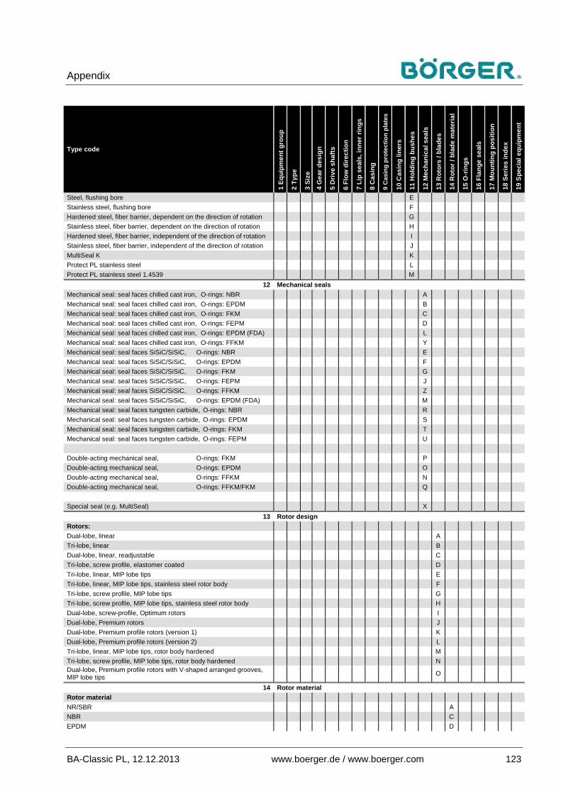
Appendix
BA-Classic PL, 12.12.2013 www.boerger.de / www.boerger.com 123
Type code
1 Eq
uipm
ent g
roup
2 Ty
pe
3 Si
ze
4 G
ear d
esig
n
5 D
rive
shaf
ts
6 Fl
ow d
irect
ion
7 Li
p se
als,
inne
r rin
gs
8 C
asin
g
9 C
asin
g pr
otec
tion
plat
es
10 C
asin
g lin
ers
11 H
oldi
ng b
ushe
s
12 M
echa
nica
l sea
ls
13 R
otor
s / b
lade
s
14 R
otor
/ bl
ade
mat
eria
l
15 O
-rin
gs
16 F
lang
e se
als
17 M
ount
ing
posi
tion
18 S
erie
s in
dex
19 S
peci
al e
quip
men
t
Steel, flushing bore E Stainless steel, flushing bore F Hardened steel, fiber barrier, dependent on the direction of rotation G Stainless steel, fiber barrier, dependent on the direction of rotation H Hardened steel, fiber barrier, independent of the direction of rotation I Stainless steel, fiber barrier, independent of the direction of rotation J MultiSeal K K Protect PL stainless steel L Protect PL stainless steel 1.4539 M
12 Mechanical seals Mechanical seal: seal faces chilled cast iron, O-rings: NBR A Mechanical seal: seal faces chilled cast iron, O-rings: EPDM B Mechanical seal: seal faces chilled cast iron, O-rings: FKM C Mechanical seal: seal faces chilled cast iron, O-rings: FEPM D Mechanical seal: seal faces chilled cast iron, O-rings: EPDM (FDA) L Mechanical seal: seal faces chilled cast iron, O-rings: FFKM Y Mechanical seal: seal faces SiSiC/SiSiC, O-rings: NBR E Mechanical seal: seal faces SiSiC/SiSiC, O-rings: EPDM F Mechanical seal: seal faces SiSiC/SiSiC, O-rings: FKM G Mechanical seal: seal faces SiSiC/SiSiC, O-rings: FEPM J Mechanical seal: seal faces SiSiC/SiSiC, O-rings: FFKM Z Mechanical seal: seal faces SiSiC/SiSiC, O-rings: EPDM (FDA) M Mechanical seal: seal faces tungsten carbide, O-rings: NBR R Mechanical seal: seal faces tungsten carbide, O-rings: EPDM S Mechanical seal: seal faces tungsten carbide, O-rings: FKM T Mechanical seal: seal faces tungsten carbide, O-rings: FEPM U Double-acting mechanical seal, O-rings: FKM P Double-acting mechanical seal, O-rings: EPDM O Double-acting mechanical seal, O-rings: FFKM N Double-acting mechanical seal, O-rings: FFKM/FKM Q Special seal (e.g. MultiSeal) X
13 Rotor design Rotors: Dual-lobe, linear A Tri-lobe, linear B Dual-lobe, linear, readjustable C Tri-lobe, screw profile, elastomer coated D Tri-lobe, linear, MIP lobe tips E Tri-lobe, linear, MIP lobe tips, stainless steel rotor body F Tri-lobe, screw profile, MIP lobe tips G Tri-lobe, screw profile, MIP lobe tips, stainless steel rotor body H Dual-lobe, screw-profile, Optimum rotors I Dual-lobe, Premium rotors J Dual-lobe, Premium profile rotors (version 1) K Dual-lobe, Premium profile rotors (version 2) L Tri-lobe, linear, MIP lobe tips, rotor body hardened M Tri-lobe, screw profile, MIP lobe tips, rotor body hardened N Dual-lobe, Premium profile rotors with V-shaped arranged grooves, MIP lobe tips O
14 Rotor material Rotor material NR/SBR A NBR C EPDM D

Appendix
124 www.boerger.de / www.boerger.com BA-Classic PL, 12.12.2013
Type code
1 Eq
uipm
ent g
roup
2 Ty
pe
3 Si
ze
4 G
ear d
esig
n
5 D
rive
shaf
ts
6 Fl
ow d
irect
ion
7 Li
p se
als,
inne
r rin
gs
8 C
asin
g
9 C
asin
g pr
otec
tion
plat
es
10 C
asin
g lin
ers
11 H
oldi
ng b
ushe
s
12 M
echa
nica
l sea
ls
13 R
otor
s / b
lade
s
14 R
otor
/ bl
ade
mat
eria
l
15 O
-rin
gs
16 F
lang
e se
als
17 M
ount
ing
posi
tion
18 S
erie
s in
dex
19 S
peci
al e
quip
men
t
FKM I PUR P Stainless steel, 1.4404 E Steel 1.7225, tempered S PTFE T CSM H Stainless steel, 1.4539 J NBR, light-colored K EPDM, light-colored L H-NBR M
15 O-rings, static NBR C EPDM D FKM I FEPM J FFKM Z FEP/FKM T EPDM (FDA) L
16 Flange seals NBR C EPDM D FKM I PTFE base T
17 Mounting position
Standing pump, feet downwards (M1) 1 Pump vertically positioned, cover downwards, feet at the side (M2) 2 Pump upside-down, feet upwards (M3) 3 Pump turned 90° to the left, feet to the right* (M5) 5 Pump turned 90° to the right, feet to the left* (M6) 6 * when looking at the quick-release cover
18 Series index
See above see
above
19 Special equipment Seal monitoring / conductivity measurement in intermediate chamber D Temperature monitoring / temperature sensor in the casing cover Z Variocap as integrated overpressure protection V Quick-release cover with shaft support (integrated slide bearing) G Other special equipment or more than one optional extra X

Appendix
BA-Classic PL, 12.12.2013 www.boerger.de / www.boerger.com 125
Modification Date Reason 1 2 3 4 5 6 7 8 9 10 11 12 13 14 15 16 17 18 19

Appendix
126 www.boerger.de / www.boerger.com BA-Classic PL, 12.12.2013
Parallel keys 9.6The following parallel key lengths must be adhered to and checked when replacing rotors on the PL pump series (Classic, Select, Protect).
Notice
Imprecise parallel key lengths can lead to misalignment of the rotating holding bush and can cause mechanical damage to the pump or to the complete unit.
Position: Rotors: Parallel key dimensions / article no.
PL 100: PL 200: PL 300: PL 400:
9.4
Type A
Dual-lobe, linear, polymers
14 x 9 x 24 mm .55 x .35 x .94" S14338
14 x 9 x 79 mm .55 x .35 x 3.11" S14348
14 x 9 x 134 (70 + 64) mm .55 x .35 x 5.28" (2.76 + 2.52") S14358
14 x 9 x 190 (100 + 90) mm .55 x .35 x 7.48" (3.94 + 3.54") S14368
Cover disk
integrated
9.5
Type I*
Optimum rotor, dual-lobe, screw profile, polymers
9.6
Type J*
Premium rotor, dual-lobe, linear, polymers
9.7
Type D
Screw rotor, tri-lobe, screw profile, polymers
9.5
Types IS*, IE*
Optimum rotor, dual-lobe, screw profile, steel / stainless steel 14 x 9 x
32 mm .55 x .35 x 1.26" S14324
14 x 9 x 88 mm .55 x .35 x 3.46" Z39070
14 x 9 x 143 (80 + 63) mm .55 x .35 x 5.63" (3.15 + 2.48") Z39044
14 x 9 x 199 (100 + 99) mm .55 x .35 x 7.83" (3.93 + 3.89") Z39054
Cover disk separate
9.6
Types JS, JE
Premium rotor, dual-lobe, linear, steel / stainless steel
9.8
Type BE
Tri-lobe, linear, stainless steel**
* not available for PL 400
**special version, see supplementary operating manual

Appendix
BA-Classic PL, 12.12.2013 www.boerger.de / www.boerger.com 127
Checklist for commissioning 9.7This checklist can be used as an additional aid when commissioning a Börger rotary lobe pump. It is not a substitute for careful reading of the operating manual before commissioning the unit.
Customer: Börger order confirmation no.:
Machine number: Type code:
Your project: Order number:
Commissioning date: Delivery date:
Test point Carried out by: (date / signature)
Checked by: (date / signature)
1 Operating manual and appendices read and understood
2 Application data and operating parameters according to pump data sheet correspond to application
3 Base frame fixed correctly to solid, even surface
4 Coupling alignment within the permitted tolerance, coupling guard attached
5 Pipes laid correctly on suction and pressure side, pipes fixed and not leaking
6 Optional safety equipment installed correctly, connected and functions checked
7 Electrical connections and grounding OK, direction of pump rotation correct
8 Oil level in drive OK, transport lock removed from breather system (if present)
9 Oil level in pump gear unit OK; in M2 mounting position: screw plug replaced by breather system
10 Fluid level in the intermediate chamber of the pump is OK, breather installed in the correct position and open
11 All valves in pipes opened; check valves installed correctly
12 Noise and vibration levels normal when drive is switched on
13 Pipes checked for leaks again with pump switched on
14 Check made of the flow rate achieved and the pump pressure
15 Power consumption of drive checked to guarantee correct installation
16 Maintenance and inspection intervals organized for the machine

Appendix
128 www.boerger.de / www.boerger.com BA-Classic PL, 12.12.2013
EC Declaration of Conformity / EC Declaration of Incorporation 9.8EC Declaration of Conformity for complete units:
Appendix
BA-Classic PL, 12.12.2013 www.boerger.de / www.boerger.com 129
EC Declaration of Incorporation for pumps delivered separately:

Appendix
130 www.boerger.de / www.boerger.com BA-Classic PL, 12.12.2013
Additional documentation 9.9The lubricant list in the appendix is part of the operating manual.
Follow the instructions. ●
Further, separate supplementary operating manuals for special versions are also part of this operating manual.
Follow the instructions. ●
Supplier documentation 9.10 You must completely read the separate supplier ●
documentation and consider it accordingly to prevent damage to the equipment.
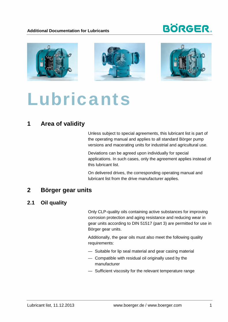
Additional Documentation for Lubricants
Lubricant list, 11.12.2013 www.boerger.de / www.boerger.com 1
Lubricants Area of validity 1
Unless subject to special agreements, this lubricant list is part of the operating manual and applies to all standard Börger pump versions and macerating units for industrial and agricultural use.
Deviations can be agreed upon individually for special applications. In such cases, only the agreement applies instead of this lubricant list.
On delivered drives, the corresponding operating manual and lubricant list from the drive manufacturer applies.
Börger gear units 2
Oil quality 2.1Only CLP-quality oils containing active substances for improving corrosion protection and aging resistance and reducing wear in gear units according to DIN 51517 (part 3) are permitted for use in Börger gear units.
Additionally, the gear oils must also meet the following quality requirements:
— Suitable for lip seal material and gear casing material — Compatible with residual oil originally used by the
manufacturer — Sufficient viscosity for the relevant temperature range

Additional Documentation for Lubricants
2 www.boerger.de / www.boerger.com Lubricant list, 11.12.2013
Notice
Risk of material damage and loss of warranty when using low-quality lubricants!
The oil classification and viscosity must be adhered to according to the factory-supplied lubricant specified in the data sheet. The lubricants used must meet the quality standards as detailed above.
Otherwise, the warranty supplied by Börger GmbH is void. Deviations are only permitted following consultation with Börger GmbH.
If the actual operating conditions on or after commissioning deviate from those specified in the order, then a change of lubricant must be considered. Any such actions must be approved by Börger GmbH.
Lubricants suitable for use in Börger gear units are listed in the table in chapter 5.1. However, the lubricant manufacturers are solely liable for the suitability and quality of their products.
According to the manufacturer's specifications, the listed lubricants are available globally in compliance with the necessary quality.
Oil change 2.2The purity of the lubricant influences the service life of the oil and gear unit, plus general operating safety.
Therefore, always ensure that the gear unit contains clean oil.
Instructions for changing the oil / lubricant contained in the operating manual of the Börger device must be strictly adhered to.
The amount of remaining used oil in the gear unit must be kept as low as possible, even when the same oil type is used for the oil change.
Note
Gear oils of different types or from different manufacturers must not be mixed together.

Additional Documentation for Lubricants
Lubricant list, 11.12.2013 www.boerger.de / www.boerger.com 3
When necessary, a confirmation of oil compatibility with the used oil must be obtained from the manufacturer of the new oil.
If the composition of the new oil type deviates greatly from the used oil (e.g. additives), then the used oil must be completely removed from the gear unit. In this case, the gear unit must be flushed carefully with the new oil. Gear oils must not become contaminated with other substances, including any residue from cleaning agents (e.g. petrol). Therefore, flushing with petrol or other cleaning agents is not permitted.
Börger intermediate chamber 3Most Börger devices are equipped with an intermediate chamber as standard. This chamber is filled with an unpressurized fluid. This protective fluid is used for the following:
— Collection of any pumped / flow media that enter the intermediate chamber due to leaks in the mechanical seal (protection of the gear unit against penetration of pumped / flow media)
— Monitoring of the mechanical seal through periodical or continuous determination of the fill level
— Lubrication and cooling of sliding surfaces on the mechanical seal
— Air exclusion (especially important for pumped media that react negatively with air)
Any fluids with good lubricant qualities that do not react with any of the materials they come into contact with are suitable as quench fluids.
Pay attention to compatibility with the residual quench fluid when filling or refilling.
Additional Documentation for Lubricants
4 www.boerger.de / www.boerger.com Lubricant list, 11.12.2013
Notice
Risk of material damage when using wrong lubricants!
Due to the possibility, though unlikely, of quench fluid entering the pump / cutting chamber and thus intruding on the process itself, the quench fluid must be compatible with the pumped / flow medium in addition to the other materials (O-rings).
In order to rule out damage to the gear unit as comprehensively as possible, even in the exceptional case that quench fluid enters the gear unit (e.g. due to improper maintenance of the gear unit), the quench fluid should also be compatible with the gear oil. In Börger devices, the quench fluid is:
— Zinc-free hydraulic oil as standard, or
— A synthetic gear or hydraulic oil (CLP / HLP) on ATEX versions
See table in chapter 5.2.
Notice
Risk of material damage when using wrong lubricants!
Versions used for special applications and / or those with special sealing materials (e.g. EPDM), can be filled with special lubricants, such as:
— Castrol Optileb HY 68 (food quality)
— Sugar-dissolving oil (Klüberfood NH 1 6-10) — Solvents (lacquer)
— Other special lubricants
Filling with these lubricants is approved / tested specifically for the supplied version and is indicated in the data sheet. In such cases, the same quench fluid must be used exclusively when filling or refilling. Otherwise, there is a risk of material damage, which can be significant depending on the application.

Additional Documentation for Lubricants
Lubricant list, 11.12.2013 www.boerger.de / www.boerger.com 5
Oil properties 4 Oil classifications 4.1
The oil classifications of applicable oils are specified in chapter 5 next to each lubricant.
Observe chapter 3 for details on the intermediate chamber. In certain applications, oil may not be permitted for use as a lubricant.
Explanation of classification according to DIN
Classification according to DIN 51524-2 HLP
High-performance hydraulic oil (H), with corrosion protection (L) and high-pressure additives (EP)
Classification according to DIN 51517-1 to -3
C Can be used as lubricating oil
CL Circulating oil, C-oil with corrosion protection
CLP Industrial gear oil, CL-oil with EP additives (high-pressure additive)
Additional letters according to DIN 51502 HC Synthetic hydrocarbons
Operating temperatures 4.2Compared to mineral oils, synthetic oils can be used in a wider operating temperature range, whereupon the temperature-related viscosity deviation is lower (higher viscosity index).
Therefore, only use synthetic, high-quality industrial gear oil in gear units in potentially explosive atmospheres. Alternatively, a synthetic high-performance hydraulic oil can be used in the intermediate chamber.
We recommend adhering to the following limits for lubricants used in Börger devices:
Mineral oils up to +80 °C (176 °F) Hydraulic oil (zinc-free, quench only) up to +80 °C (176 °F)
Synthetic oils up to +100 °C (212 °F) (for short periods +110 °C (230 °F))
Note
Special lubricants for higher operating temperatures can be delivered on agreement. In this case, the agreed limits apply.

Additional Documentation for Lubricants
6 www.boerger.de / www.boerger.com Lubricant list, 11.12.2013
The specified values are recommended guidelines.
Consult the technical data sheets of the relevant lubricant manufacturer for their specified operating temperature ranges and other oil property details.
Oil service life 4.3The general service life at average temperatures in gear units without a significant change in oil quality is approximately 2 years or 10,000 operating hours.
In potentially explosive atmospheres, an oil change should be made annually or after 8,000 operating hours.
The actual service life can increase or decrease significantly depending on the operating conditions. Therefore, check the oil level and oil quality on a regular basis.
This also applies to the quench fluid.
Oil types 5 Applicable lubricants in Börger gear units 5.1
Viscosity class 1) Label / DIN classification Pour
point Flash point
ISO VG 220
ARAL Degol BG 220 CLP -12 °C 10.4 °F
274 °C 525.2 °F
BP Energol GR XP 2202) CLP -21 °C
-5.8 °F 274 °C
525.2 °F Enersyn HTX 220 CLP HC (PAO4)) -36 °C
-32.8 °F 270 °C 518 °F
CASTROL
Alpha SP 220 CLP -21 °C -5.8 °F
226 °C 438.8 °F
Alphasyn T 220 CLP HC (PAO4)) -45 °C -49 °F
220 °C 428 °F
Aphasyn HTX 2203) CLP HC (PAO4)) -39 °C -38.2 °F
220 °C 428 °F
ESSO Spartan EP 220 CLP -24 °C -11.2 °F
255 °C 491 °F
Klüber Lubrication Klüberoil GEM 1-220 CLP -10 °C 14 °F
> 200 °C > 392 °F
SHELL Omala Oil F 220 CLP -27 °C -16.6 °F
240 °C 464 °F
1) i.e. viscosity v = 220 mm²/s (cSt) at 40 °C (104 °F) 2) Börger factory standard, unless agreed otherwise 3) Börger factory standard for ATEX versions and for Protect pumps 4) PAO = polyalphaolefin-based fully synthetic base oils

Additional Documentation for Lubricants
Lubricant list, 11.12.2013 www.boerger.de / www.boerger.com 7
Applicable lubricants in Börger intermediate chambers 5.2
Notice
Risk of material damage when using wrong lubricants!
Check the quench fluid specifications in the data sheet before filling / refilling the intermediate chamber.
Only use a lubricant with the same classification.
When the device was delivered with special lubricants for special applications or seal materials, only use the same fluid as originally applied by the manufacturer. This fluid has been tested for the version. Alternative quench fluids may only be used following consultation with Börger GmbH. Otherwise, there is a risk of material damage, which can be significant depending on the application.
Viscosity class 1) Label / DIN classification Pour
point Flash point
ISO VG 68
ARAL Vitam GF 68 2) HLP (only zinc-
free!) -18 °C -0.4 °F
258 °C 496.4 °F
Degol BG 68 CLP -30 °C -22 °F
242 °C 467.6 °F
BP Energol CS 68 C
-15 °C 5 °F
235 °C 455 °F
Enersyn HTX 68 CLP HC (PAO4)) -42 °C -43.6 °F
270 °C 518 °F
CASTROL
Magna 68 C -18 °C -0.4 °F
220 °C 428 °F
Alphasyn T 68 CL HC (PAO4)) -57 °C -70.6 °F
220 °C 428 °F
Alphasyn HTX 68 3) CLP HC (PAO4)) -39 °C -38.2 °F
220 °C 428 °F
ESSO Nuray 68 C -18 °C -0.4 °F
230 °C 446 °F
Klüber Lubrication Klüberoil GEM 1-68 CLP -15 °C 5 °F
> 200 °C > 392 °F
SHELL Vitrea 68 C -9 °C 16 °F
223 °C 433.4 °F
1) i.e. viscosity v = 68 mm²/s (cSt) at 40 °C (104 °F) 2) Börger factory standard, unless agreed otherwise 3) Börger factory standard for ATEX versions 4) PAO = polyalphaolefin-based fully synthetic base oils We reserve the right to make technical alterations. Errors cannot be excluded.