brick masonry 24 & siding - mr. wilsons technology...
TRANSCRIPT
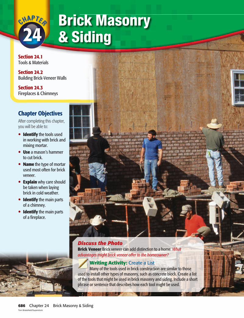
Brick Masonry & Siding
Chapter ObjectivesAfter completing this chapter, you will be able to:
• Identify the tools used in working with brick and mixing mortar.
• Use a mason’s hammer to cut brick.
• Name the type of mortar used most often for brick veneer.
• Explain why care should be taken when laying brick in cold weather.
• Identify the main parts of a chimney.
• Identify the main parts of a fi replace.
Section 24.1Tools & Materials
Section 24.2Building Brick-Veneer Walls
Section 24.3Fireplaces & Chimneys
24
Discuss the PhotoBrick Veneer Brick veneer can add distinction to a home. Whatadvantages might brick veneer offer to the homeowner?
Writing Activity: Create a List Many of the tools used in brick construction are similar to those
used to install other types of masonry, such as concrete block. Create a list of the tools that might be used in brick masonry and siding. Include a short phrase or sentence that describes how each tool might be used.
686 Chapter 24 Brick Masonry & Siding Tom Brakefi eld/Superstock

24
NCTE National Council of Teachers of EnglishNCTM National Council of Teachers of Mathematics
NSES National Science Education Standards
1. Gather the bricks, a brick hammer, and a brick set.
2. Line the bricks up evenly.
3. Use a straightedge to scribe a line across the bricks.
Go to glencoe.com for this book’s OLC for a downloadable version of this graphic organizer.
Content Vocabulary
Academic VocabularyYou will fi nd these words in your reading and on your tests. Use the academic vocabulary glossary to look up their defi nitions if necessary.
■ initial ■ transmission ■ prolonged
Graphic OrganizerAs you read, use a chart like the one shown to organize events in a sequence. For example, you could list the steps of how to cut a brick in half across its width with a hand tool.
Before You Read PreviewBrick masonry is a popular building material that has many uses, including residential siding, chimneys, and fi replaces. Before reading the chapter, list some ways in which you think brick masonry is used as a building material in the construction of a new home.
Academic Standards
Mathematics
Number and Operations: Compute fl uently and make reasonable estimates (NCTM)Geometry: Use visualization, spatial reasoning, and geometric modeling to solve problems (NCTM)Algebra: Represent and analyze mathematical situations and structures using algebraic symbols (NCTM)
English Language Arts
Conduct research and gather, evaluate, and synthesize data to communicate discoveries (NCTE 7)Use language to accomplish individual purposes (NCTE 12)
Industry StandardsExterior Finishing
●● jointer●● retempering●● weep hole●● lintel
●● lead corner●● line block●● fi rebox
●● makeup air●● refractory cement●● hearth
●● draft●● fl ue●● corbel
Chapter 24 Reading Guide 687

Toe or point Heel Ferrule
HandleShank
Frog
Brick Masonry ToolsAre hand tools better than power tools for cutting brick?
Brick comes in many colors and shapes. On some houses, it covers the entire surface of every exterior wall, while on others it is used on just some of the walls. In every case, it should be applied by skilled brick masons using suitable tools. This ensures that the brick will properly protect the house.
Hand ToolsMany of the tools used in brick construc-
tion are similar to those used to install other types of masonry, such as concrete block (see Chapter 10). Brick Trowel The brick mason’s basic tool is the brick trowel. The trowel has a steel blade and a wood handle. The end of the blade is called the toe, or point. The wide portion is called the heel, as shown in Figure 24-1. Trowels are available in many sizes and in two main shapes:Philadelphia Pattern A Philadelphia trowel has a blade with a squared-off heel. It is best suited to laying block because it holds more mortar.London Pattern This trowel has a rounded heel and is the pattern used most for laying
brick. The shape of the blade holds less mortar than a Philadelphia trowel, and mortar tends to be supported more toward the toe of the trowel.
The width of a trowel, measured at the heel, is often between 5" and 51⁄2". The most popular length is 11". However, each mason should fi nd a style and size of trowel that feels good in the hand. Some masons fi nd that short, wide trowels are most comfort-able to use because their weight, when loaded with mortar, is centered nearer the handle. This puts less strain on the mason’s wrist. Wood handles and cushioned-wood handles are available.
Jointer A jointer, or jointing tool, is a simple metal bar with a shaped end, such as the one in Figure 24-2. It is run over the joints to pack the mortar into them and give them a particular shape.
Mason’s Level A good quality mason’s level, shown in Figure 24-3, is another important tool for the brick mason. It should have horizontal and vertical leveling vials that can be read from both sides. The edges should be metal to withstand wear.
Mason’s Rule A mason’s rule, shown in Figure 24-4, is used for measuring the height and spa-cing of brick courses (rows) as they are laid.
Tools & Materials24.1
Figure 24-1 Brick TrowelBasic Anatomy The main parts of a brick trowel.
688 Chapter 24 Brick Masonry & Siding Arnold & Brown

A folding rule is preferred over a tape mea-sure because the tape can be damaged by contact with mortar. Two types of folding rule are available. The standard mason’s rule is white. It is used for measuring standard, or modular, brick. An oversized mason’s rule is yellow. It is easier to use when working with oversized bricks.Brick Tongs Brick tongs help masons carry small quantities of brick effi ciently, as shown in Figure 24-5. The metal tool clamps over a row of six to eleven bricks. The lever action of the handle holds the bricks in place. When the handle is lowered, the bricks are released. Brick Hammer A brick hammer, shown in Figure 24-6, is used for splitting and rough-breaking bricks. It often has a hardwood handle. The head has a chisel blade (some-times called the peen end) and a square face.
Figure 24-2 JointersTwo Styles A jointer is used to form and compact mortar joints. Various types are available.
Figure 24-4 Mason’s RuleBrick Measurements The front side of the rule reads in feet and inches. The back side of the rule is marked with brick coursing dimensions.
Figure 24-3 Mason’s LevelsDurable Wood Mason’s levels are available in various sizes. These are traditional mahogany levels.
Figure 24-5 Brick TongsQuality Control Tongs reduce the damage that might occur to bricks if they were just dumped into a wheelbarrow.
Figure 24-6 Brick HammersEssential Tools These brick hammers have wood handles and carbide chisel ends.
Section 24.1 Tools & Materials 689Arnold & Brown; David R. Frazier Photolibrary, Inc.

Brick set
B
A
Cutting BrickCutting brick with hand tools is often the
easiest and quickest method. To cut brick with a brick hammer, make a cutting line around the brick by striking it lightly and repeatedly with the square face. A sharp blow to one side of the completed cutting line will then split the brick along the line, as shown in Figure 24-7. Rough surfaces can be cleaned up somewhat with the chisel blade.
To cut a brick in half across its width, use a brick hammer and brick set, as shown in Figure 24-8. If several bricks must be cut to the same size, line them up evenly. Then use a straightedge to scribe a line across them. This limits variations in the sizes of the cut brick.
Brick BasicsWhy are there so many sizes of brick?
Like concrete block and similar materi-als, brick is categorized as a unit masonry product. Unit masonry consists of individual pieces of material that can be assembled into larger structures using mortar.
Brick is produced in factories by crushing clay and shale, tempering it with water, forming it into bricks, and then drying the bricks in large kilns (ovens). Other
Figure 24-8 Cutting Across the WidthBrick Set Using a brick hammer and brick set to cut brick.
Figure 24-7 Cutting Across the LengthHalf Size Cutting brick in half lengthwise. A. Splitting the brick along the cutting line using a brick hammer. B. Trimming brick with the hammer’s chisel blade.
Brick Set A brick set is a chisel-like tool made of tempered steel. One edge is beveled. Strik-ing the brick set with a brick hammer cuts a brick cleanly. A brick set is shown in use in Figure 24-8.
Power ToolsIn some cases it is most effi cient to cut brick
with a tool such as a brick masonry saw (also called a brick saw). These tools are smaller and more portable than saws used to cut block and can cut to a depth of 31⁄4" or 5", depending on model. The saws typically include a small pump that sprays water to lubricate the blade and reduce dust. Brick is a harder but less abrasive material than block, so it should be cut with a diamond blade designed specifi cally for brick. Blades are available for cutting brick dry, but the process generates a great deal of dust that is hazardous to breathe.
690 Chapter 24 Brick Masonry & Siding
Handling Masonry Products Masonry products are heavy. Do not bend over as you lift. Always lift moderately heavy loads by bending at the knees and use machinery to lift heavy loads. For example, loads of brick or bags of mortar can be transported on pallets and moved with a forklift to a point near where they will be used.
Go to glencoe.com for this book’s OLC for more on job safety.
ingredients may be added during manufac-ture to improve some qualities of the brick. The tempered material is formed into bricks in one of three basic ways:• By extruding the material through dies
and slicing it into individual bricks.• By placing the material into individual
molds.• By dry-pressing the material under high
pressure.
TypesThe suitability of a brick for a particular
use depends on several factors. These include the type and source of the clay and how the brick was manufactured. Many types of bricks are available. Following are the three basic types:
Building Brick Building brick is a strong, general-purpose brick. Its color varies from brick to brick. Sizes are somewhat inconsistent.Facing Brick Facing brick is used primarily for exposed exterior surfaces such as veneer walls. Because manufacturing is carefully controlled, the resulting bricks are consistent in size, texture, and color.Fire Brick Fire brick is usually pale yellow or buff in color. It is used specifi cally for lining fi replaces and other heating units. It is sometimes referred to as refractory brick.
Bricks with holes (cores) through them are called hollow bricks, or sometimes cored bricks. Those without holes are called solid bricks. Both kinds of bricks are suitable for veneer walls. During fi ring, the cores enable the bricks to dry and harden more evenly. Firing is a process that heats the brick to temperatures as high as 2,400°F (1,316°C). Bricks with cores are also less expensive to produce, because they use less clay and the fi ring process uses less fuel. Because they weigh less, they are less expensive to ship and easier to lay. One other advantage is that when mortar oozes into the cores, it makes a very strong mechanical connection.
Some hollow bricks have three fairly large cores. Others have ten or more smaller cores. The exact arrangement is determined by the manufacturer. However, the overall area of coring must not be more than 60 percent of the brick’s surface.
A depression in one bedding surface of a solid brick is called a frog, or sometimes a panel. A frog serves a purpose similar to that of a core. Frogs are limited to a specifi ed depth and a specifi ed distance from the brick’s face. Bricks should always be laid with the frogged surface down.
SizesFor many years, only three sizes of bricks
were available: standard, Roman, and Norman. Today there are hundreds of sizes,
Brick Dust and Fragments Cutting brick by hand can launch small pieces of brick toward you. Wear suitable eye protection. If cutting with a dry-cut masonry saw, wear a dust mask so as not to breathe in the fi ne brick dust. Always wear eye protection.
Go to glencoe.com for this book’s OLC for more on job safety.
Section 24.1 Tools & Materials 691

THREE-INCH
STANDARDMODULAR
ENGINEER
ROMAN NORMAN NORWEGIAN ECONOMY 12 ORJUMBO UTILITY
DOUBLECLOSURE
STANDARD
NONMODULAR BRICK (actual dimensions)
MODULAR BRICK (nominal dimensions)
OVERSIZE
3" 31/4"91/4"or 93/4" 8"
21/4"or 23/4" 21/4"
4"
4" 4" 4" 4"
8"
21/4"
21/4"
4"8"
31/2"
31/2"
4"
4"2"
12" 12" 12" 12"
8"
4"
4"8"
8"
31/4" 8"
23/4"
including those shown in Figure 24-9. When specifying the size of a brick, always list the dimensions in the following order: thickness by height by length.
All brick can be classifi ed into two size groups: modular and nonmodular. The length of a modular brick is based on mul-tiples of 4". It is a nominal size that includes an allowance for the thickness of a standard 3⁄8" mortar joint. The actual dimensions of a modular brick are therefore smaller than the nominal dimensions, just as the actual dimensions of a 2�4 stud are smaller than its nominal dimensions.
The size of nonmodular brick does not take the thickness of the mortar joint into account. The dimensions given for non-modular brick are the actual dimensions.
Figure 24-9 Sizes of Modular/Nonmodular BrickCommon Sizes Sizes of modular and nonmodular brick, shown with nominal and actual dimensions.
Brick Height Regular modular and nonmodular building brick are different lengths but they are always the same height. Specialty brick may be different heights. This is because brick manufactur-ers who fi rst introduced modular brick wanted the material to match the cours-ing of nonmodular brick walls. That way builders could use the new brick when adding on to houses built with the old brick. That is why reference tables that list course heights for brick walls apply to either type of brick.
692 Chapter 24 Brick Masonry & Siding

AStretcher
BHeader
CRowlock
DShiner
ESailor
FSoldier
Volume and Surface Area A Roman brick is a nonmodular brick that is 12 inches long, 4 inches wide, and 2 inches thick. If you cut a Roman brick into two equal parts along any of its dimensions, will its volume increase, decrease, or stay the same? What will happen to its surface area?Starting Hint Make a chart showing volume and surface area of a whole brick and the brick cut into two in various ways.
Geometry
TexturesAlong with color and size, bricks vary in
texture. The texture of a brick can signifi -cantly affect its appearance. Some bricks have smooth surfaces. Others may have a wirecut (velour), brushed, or other type of rough texture.
Brick Positions and BondsA brick can be mortared into place in
any one of six basic positions shown in Figure 24-10. Some of these positions are
used to strengthen a wall, while others are used primarily for decorative purposes. A skilled mason should know how to install brick in each of these positions. A row of brick in one position is called a course. Thus a row of brick arranged as in Figure 24-10A would be called a stretcher course.
There are many ways to position the bricks in a wall to create various patterns. These patterns are called bonds. The bond used on a brick project affects the look of a wall as well as its cost, strength, and ease of construction. For example, if each brick was stacked directly above the brick below, this would be called a stacked bond. It would result in a grid-like pattern of mortar joints but would not create an especially strong wall. Another bond is called a running bond or a stretcher bond. In this method, each brick is centered directly over the joint between the two bricks below. In other words, each brick overlaps adjacent bricks by one-half its length. This is the method used most often in residential brick con-struction. All illustrations in this chapter show a running bond.
Figure 24-10 Brick PositionsSix Possibilities Bricks can be installed in these basic positions: A. Stretcher B. Header C. Rowlock D. Shiner E. Sailor F. Soldier. The darkened surface is the one that would be exposed in a wall.
Section 24.1 Tools & Materials 693

Mortar BasicsWhat effect would hot weather have on mortar?
Mortar holds bricks together as they are laid. Its bond strength is its most important quality. Mortar must be durable and have enough bearing capacity to support the brick. It must also block the passage of water.
The basic dry ingredients of mortar are Portland cement, masonry cement, hydrated lime, and sand. When mixed with clean water, these ingredients form a durable and easily worked material.
Types of MortarDifferent types of mortar are needed for
different types of brick construction. They vary as to ingredients and proportions. Fol-lowing are the four basic types of mortar:Type M This type is recommended specifi -cally for masonry below grade and in contact with soil. Uses include foundations, retain-ing walls, and walkways.Type S This type is recommended when the brick must resist high levels of lateral (sideways) force. It may be required in areas of high earthquake activity.Type N This type is a general-purpose mortar for brick-veneer walls. It is suitable for gen-eral use in exposed masonry above grade. It is recommended specifi cally for exterior walls exposed to severe weather conditions.Type O This type is used for load-bearing walls that will not be subjected to moisture and freeze/thaw cycles.
Mixing MortarMixing proportions for these basic types
of mortar are shown in Table 24-1. Measure-ments should be made carefully. A common mistake is to add too much sand. A fi ner sand requires a greater proportion of cement to produce a workable mix. Colorants may also be added to change the appearance of mortar. This is sometimes done to comple-ment the color of the brick.
The proper amount of water to use in mix-ing mortar is often misunderstood. Mortar should not be confused with concrete. Concrete is mixed with the least amount of water possible in order to maximize its abil-ity to bear heavy loads. Mortar, on the other hand, requires workability and high bond strength. Mortar is considered workable if it spreads easily and will readily stick to verti-cal surfaces. Another difference between the two materials is that concrete does not contain lime.
Unlike concrete, mixed mortar may be retempered. Retempering is the process of adding water to a batch of mortar that has become too stiff to work. Only enough water is added to replace that lost by evaporation. Also, mortar should be used within 21⁄2 hours after initial mixing if the air temperature is 80°F (27°C) or higher. Cooler weather allows a somewhat longer working time.
If a large volume of mortar is required, it may be mixed in a mortar mixer (sometimes called a power mixer or mechanical mixer), such as the one in Figure 24-11. It is similar
TypePortland Cement-Lime Mortars
SandPortland Cement
Hydrated Lime or Lime Putty
M 1 ¼ 3S 1 ½ 4½N 1 1 6O 1 2 6
TypeMasonry Cement Mortars
SandPortland Cement
Masonry Cement Type II
M 1 1 6S ½ 1 4½N — 1 3O — 1 (Type I or II) 3
Note: Numbers represent parts. For example, “1 part lime to 6 parts water.”
Table 24-1: Mortar Proportions by Volume
694 Chapter 24 Brick Masonry & Siding

to a concrete mixer, except that the mix-ing drum does not rotate. Instead, mixing paddles inside the drum are turned by a heavy-duty electric motor or a gas engine. Mortar ingredients are added to the drum and blended by the rotating paddles. All the dry ingredients should be measured and placed in the mixing drum and mixed for one minute before clean water is added. The mixer should continue to run until the ingredients are thoroughly blended.
A mortar mixer should be maintained regularly. This includes cleaning the mixing drum thoroughly after use. Any drive belts should be checked for proper tension, and the retractable guard over the mixing drum must work smoothly. Mortar should not be allowed to dry on the mixer’s moving parts, particularly on the drive gears.
Small amounts of mortar may be mixed in a wheelbarrow. However, a steel mortar box is less likely to tip over. A mortar hoe is used to blend the ingredients. It has holes in the blade to make mixing easier. Blend all the dry ingredients, and then add clean water as needed. Do not let the hoe or any other mixing tools come into contact with dirt.
Figure 24-11 Mortar MixerHigh-Volume Mixing Mortar mixers come in capacities of 7, 9, and 12 cubic feet.
After You Read: Self-Check1. What is the term used to describe the wide portion of a brick trowel blade?2. Name two safety precautions to be taken when cutting brick.3. How should a mortar mixer be maintained?4. What must be done before adding water to a mortar mixture?
Academic Integration: English Language Arts5. Brick Trowels The brick mason’s basic tool is the brick trowel. Write a one-paragraph
description of the brick trowel. Name its components and uses. State how it is best used.
Go to glencoe.com for this book’s OLC to check your answers.
24.1
Section 24.1 Tools & Materials 695David R. Frazier Photolibrary, Inc.

Construction DetailsWhat supports a brick-veneer wall?
In residential construction, a layer of brick may be used for part or all of the exterior covering over standard wood-frame walls and sheathing. This is called brick-veneer siding, or more often, brick veneer. Brick is also sometimes used as a load-bearing struc-tural material, rather than as veneer. These types of walls are called cavity walls. This is because the walls consist of two layers of brick separated by an air space, or cavity. This chapter will focus on brick veneer, because this is the most common use of brick wall in modern residential construction.
One advantage of brick veneer over wood materials is that it reduces the transmission of sound to the inside of the house. Another advantage is brick’s natural fi re resistance. Although fairly high in cost, brick has low maintenance requirements and a long life. In addition, it is versatile and suitable for a variety of architectural styles.
For brick veneer to protect the house, it must be installed with skill. All mortar joints must be fully fi lled because partially fi lled joints allow water to pass through. This can
Building Brick-Veneer Walls 24.2
cause wood sheathing behind the wall to rot. It can also damage the wall when water freezes and expands in the joints. However, if too much mortar is used, it will squeeze out and stain the bricks below. All mortar joints should be fi lled so that some mortar is forced out of the joint when the brick is set. In this way a full bond is achieved. The mor-tar momentarily hangs on the brick until the mason cleans the excess off with a trowel. If done properly there is no mortar that falls on the ground. It is equally important to keep mortar out of areas intended to let moisture drain from behind the wall. Brick courses should be straight and level. In addition, vertical joints must fall in regular patterns that are plumb.
A brick-veneer wall must be supported by a masonry or concrete foundation and be tied into the framework of the house, as shown in Figure 24-12. The brick rests on a supporting ledge or shelf formed into the main house foundation. This ledge is often fl ashed. This ledge is approximately 5" wide, which allows the brick to be spaced at least 1" away from the sheathed wall. If moisture penetrates the wall, this air space will allow the water to drain out through gaps in the bottom of the wall. This space also prevents mortar from blocking the drainage plane.
The fi rst course of brick is a leveling course intended to make up for any irregularities in the support ledge. Subsequent courses should be checked frequently for level and plumb. When a house has deep overhangs, they are often framed as shown in Figure 24-13. At the top of the veneer wall, building code calls for a gap of at least 3⁄4" between the brick and the underside of the soffi t framing. Cove molding can be used to conceal the joint between the soffi t material and the brick. The cove mold-ing should be attached to the underside of the soffi t material, not to the brick.
Brick Masonry & Earthquakes In areas of the country where the risk of seismic activity is high, extra precautions must be taken to ensure that brick-veneer walls will not topple. These may include restricting the height of the wall, installing additional wall ties, and limiting the type of mortar allowable.
Go to glencoe.com for this book’s OLC for more information about regional concerns.
696 Chapter 24 Brick Masonry & Siding

Sheathing paper
Sheathing
Base flashing extends behind sheathing paper
Maintain 1" space between sheathing and back of veneer
Weep hole
Metal ties fasten to studs
Brick veneer
5"
3/4" Clearanceminimum
Wall tie
Wall studSheathing
Cove molding
LookoutSoffit
Brick veneer
Air space
Another way to handle veneer at the soffi t is to continue the brick veneer into the soffi t cavity by adding one course of brick to the wall. The horizontal framing forming the soffi t can then be butted into
the side of the veneer. Cove molding would be used to conceal the joint. This method is suitable for relatively short overhangs but increases the amount of brick that must be used.
Figure 24-13 Brick Veneer at the Soffi tPlanning for Movement If soffi ts are framed in this manner, a gap is necessary between the brick and the wood framing to allow for movement.
Figure 24-12 Brick Veneer at the FoundationSupport and Drainage Details of brick-veneer construction supported by a concrete foundation wall.
Section 24.2 Building Brick-Veneer Walls 697
C
B
E
A
D
Flashing and DrainageIt is important to remember that no siding
is considered waterproof. Brick is no excep-tion. Materials behind the brick should be installed on the assumption that water will reach this area eventually. For example, base fl ashing should be used at the brick course below the bottom of the sheathing and fram-ing (see Figure 24-12). The top edge of the fl ashing should be slipped behind the build-ing paper or building felt already attached to the sheathed walls. This is an important detail that is often overlooked. Various fl ashing materials are acceptable, but copper is highly durable and is often preferred.
A series of weep holes must be built into the wall. A weep hole is a hole that provides drainage near the bottom of walls. Weep holes are often formed by omitting some of the mortar in a vertical joint every 18" to 24" along the wall. Moisture that builds up behind the veneer can then escape to the outside. Weep holes are located in the low-est mortar joints above grade. They may be formed by leaving out certain head joints, by inserting plastic tubing into the wall, or by creating a hole using a metal rod. Where insect infestations are a problem, plastic weep hole vents can be inserted into the
open mortar joint. The vents allow moisture to escape but prevent insects from getting behind the brick veneer.
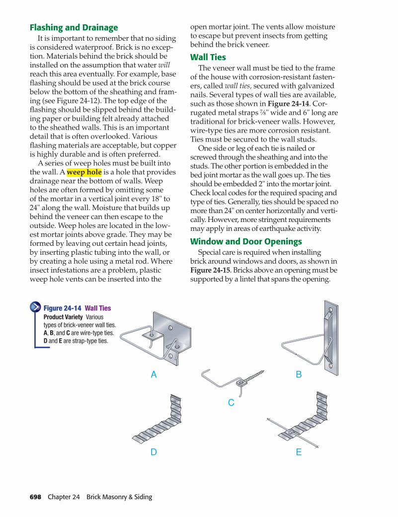
Wall TiesThe veneer wall must be tied to the frame
of the house with corrosion-resistant fasten-ers, called wall ties, secured with galvanized nails. Several types of wall ties are available, such as those shown in Figure 24-14. Cor-rugated metal straps 7⁄8" wide and 6" long are traditional for brick-veneer walls. However, wire-type ties are more corrosion resistant. Ties must be secured to the wall studs.
One side or leg of each tie is nailed or screwed through the sheathing and into the studs. The other portion is embedded in the bed joint mortar as the wall goes up. The ties should be embedded 2" into the mortar joint. Check local codes for the required spacing and type of ties. Generally, ties should be spaced no more than 24" on center horizontally and verti-cally. However, more stringent requirements may apply in areas of earthquake activity.
Window and Door OpeningsSpecial care is required when installing
brick around windows and doors, as shown in Figure 24-15. Bricks above an opening must be supported by a lintel that spans the opening.
Figure 24-14 Wall TiesProduct Variety Various types of brick-veneer wall ties. A, B, and C are wire-type ties. D and E are strap-type ties.
698 Chapter 24 Brick Masonry & Siding

Header
Lintel
Jamb
Framedwall
Sill
Corner
Line block
Mason's line
A lintel is a structural support for masonry. It can be made of solid stone, pre-cast concrete, or an L-shaped length of 1⁄4"-thick steel. In any case, a lintel must have at least 4" of bearing on each jamb. The sill below a window or door is sometimes made of a row of bricks slanted downward to shed water. This is called a rowlock. However, it is also common to install a sill made of solid stone or precast concrete.
Recall What are some advantages of brick veneer over wood materials?
Building a Veneer WallHow would you create a raked joint?
Before actually laying brick, the mason should review the plans for the house. This
will reveal any special details called for, such as arches or decorative coursing. The mason should also plan the courses of brick so that they line up with the top and bottom of window and door openings wherever possible. This reduces the need to cut brick and results in a better overall appearance. On a small project, a mason may mix mortar as well as lay brick. On larger projects, he or she may have a helper, called a tender. This person mixes mortar and provides a steady supply to the mason. The mason can then focus on laying brick. Steps for laying a brick appear on the next page.
Building Lead CornersA lead corner is a partially constructed
corner of brick, as shown in Figure 24-16. After lead corners are established at both
Figure 24-15 Wall Opening DetailsOpenings These details show a door frame installed in brick-veneer construction. Window installation would be similar.
Figure 24-16 Lead CornersKeeping Courses Straight Line blocks hooked over each lead corner of a wall hold a mason’s line in place to help keep the courses straight.
Section 24.2 Building Brick-Veneer Walls 699

Step 1 Scoop up a portion of mortar with the trowel. Spread it over three to fi ve bricks by sliding the mortar off the trowel with one smooth sweeping motion. This creates a mortar bed.
Step 2 Furrow the mortar by drawing the point of the trowel across it. This provides better coverage for the brick. However, it is important not to leave any voids in the bed joint. For this reason, some masons do not furrow the mortar.
Step 3 Pick up a brick with one hand and butter one end. Buttering means swiping a small amount of mortar over the end of the brick. This mortar will fi ll the vertical (head) joint. (An alternate method is to butter the end of a brick already in place.)
Step 4 Shove the brick into place so that the mortar squeezes out the top of the head joint.
Step 5 Using the end of the trowel handle, bed the brick by tapping the top of the brick into place. Make sure that it is level with the adjoining brick and
aligned with, but not touching, the mason’s line used for alignment.
Step 6 Slide the edge of your trowel at an angle across the bed and head joints (across the surface of the wall) to cut off mortar that has squeezed out. This prevents the mortar from staining the bricks below. Mortar that is cut off can be reused. Continue to lay brick in this fashion until reaching the end of the mortar bed. Apply a new bed and repeat the process.
Step 7 After several complete courses of brick have been laid, use a jointer to compact bed and head joints. This is called tooling the joints. The head joints should always be tooled before the bed joints. Finally, brush the wall with a mason’s brush to remove stray bits of mortar.
ends of a wall, the remaining brick is laid between them. The fi rst course of each corner is placed into a thick bed of mortar laid on the foundation wall. Additional courses are stepped upward toward the cor-ner. Work then proceeds toward the center
of the wall. This technique helps to maintain straight and level courses. Line blocks may be hooked onto the outside edges of each lead corner. In the case of an unusually long wall, an additional lead, called a middle lead, is built between the two corner leads.
Go to glencoe.com for this book’s OLC for additional step-by-step procedures, applications, and certifi cation practice.
Laying a Brick It is important for a mason to work effi ciently. Each brick should be laid using the fewest possible motions. This reduces physical stress and increases speed. Fol-lowing are the basic steps for laying brick for a wall that has already been started.
700 Chapter 24 Brick Masonry & Siding
Top extension
Adjustablesteel tape
Aluminumclamp
Line holder
Bronze clip
Baseextension
Base adapter
Top adapterLaying Brick to a LineTo ensure that a course of brick is level
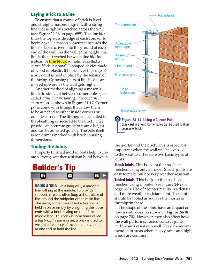
and straight, masons align it with a string line that is tightly stretched across the wall (see Figure 24-16 on page 699). The line iden-tifi es the top outside edge of each course. To begin a wall, a mason sometimes secures the line to stakes driven into the ground at each end of the wall. As the wall gains height, the line is then stretched between line blocks instead. A line block sometimes called a corner block, is a small L-shaped device made of wood or plastic. It hooks over the edge of a brick and is held in place by the tension of the string. Opposing pairs of line blocks are moved upward as the wall gets higher.
Another method of aligning a mason’s line is to stretch it between corner poles (also called adjustable masonry guides or corner story poles), as shown in Figure 24-17. Corner poles come with fi ttings that allow them to be attached to either inside corners or outside corners. The fi ttings can be nailed to the sheathing or secured to the brick. They provide an accurate guide to course height and can be adjusted quickly. The pole itself is sometimes marked with brick coursing dimensions.
Tooling the JointsProperly fi nished mortar joints help to cre-
ate a strong, weather-resistant bond between
the mortar and the brick. This is especially important when the wall will be exposed to the weather. There are two basic types of joints:Struck Joints This is a joint that has been fi nished using only a trowel. Struck joints are easy to make but not very weather-resistant.Tooled Joints This is a joint that has been fi nished using a jointer (see Figure 24-2 on page 689). Use of a jointer results in a denser and more weather-resistant joint. The joint should be tooled as soon as the mortar is thumbprint hard.
The shape of the joints have an impact on how a wall looks, as shown in Figure 24-18 on page 702. However, they also affect how the wall performs. Tooled concave joints and V-joints resist rain well. They are recom-mended in areas where heavy rains and high winds are common.
Using a Trig On a long wall, a mason’s line will sag at the middle. To provide support, masons often loop a short piece of line around the midpoint of the main line. The piece, sometimes called a trig line, is held in place simply by weighting the loose ends with a brick resting on top of the middle lead. This brick is sometimes called a trig brick. In some cases, a brick is used to weight a fl at piece of metal that has a loop at one end to hold the line.
Figure 24-17 Using a Corner PoleQuick Adjustment Corner poles can be used to align courses of brick.
Section 24.2 Building Brick-Veneer Walls 701

Working in Cold WeatherCold weather slows the hydration process
in mortar and can affect the strength of the wall. Building codes therefore include rules for the installation of masonry in cold weather. Bricks that are cold affect curing. When outdoor temperatures are below 20°F (-7°C), bricks should be warmed before use. However, it is rarely necessary to warm them to more than 40°F (4°C). If wet brick has become frozen, it must be thawed and dried completely before use.
When mixing mortar in cold weather, you may need to heat the sand and water before mixing them with the other ingredients. Mortar should never be allowed to freeze as
it is curing. This makes it less weather resis-tant. It can also reduce or destroy the bond between brick and mortar. For this reason, masons often work beneath protective tents in cold weather.
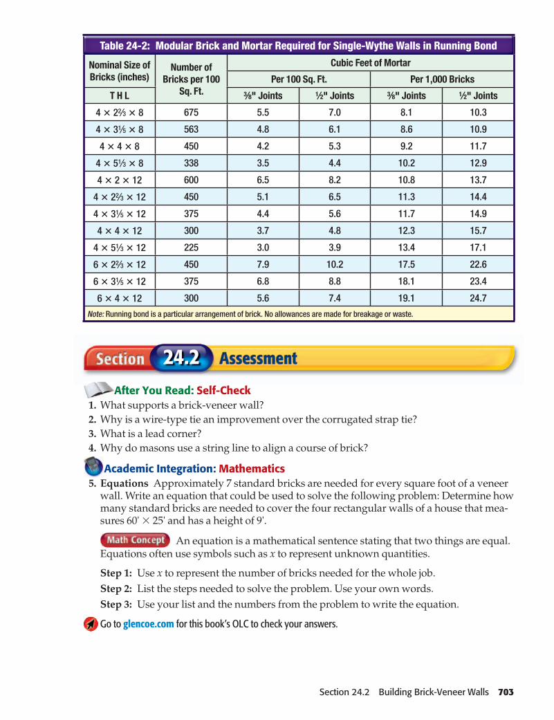
Estimating BrickA rough estimate of bricks needed may
be made based on the wall’s square footage. Approximately seven standard bricks are needed for every square foot of a veneer wall. This includes a small allowance for waste. After calculating the square footage of walls, minus any openings, multiply this fi gure by 7 to get the number of bricks required. Another method is to consult a table such as Table 24-2.
Common Types There are many brick joints but these joints are often used in construction: A. Concave. B. V-shaped. C. Weathered (also called weather-struck). D. Rough cut (also called fl ush). E. Raked.
Figure 24-18 Mortar Joint Shapes
Concave
RakedRough CutWeathered
V-Shaped
702 Chapter 24 Brick Masonry & Siding
Nominal Size of Bricks (inches)
Number of Bricks per 100
Sq. Ft.
Cubic Feet of Mortar
Per 100 Sq. Ft. Per 1,000 Bricks
T H L 3⁄8" Joints 1⁄2" Joints 3⁄8" Joints 1⁄2" Joints
4 � 22⁄3 � 8 675 5.5 7.0 8.1 10.3
4 � 31⁄5 � 8 563 4.8 6.1 8.6 10.9
4 � 4 � 8 450 4.2 5.3 9.2 11.7
4 � 51⁄3 � 8 338 3.5 4.4 10.2 12.9
4 � 2 � 12 600 6.5 8.2 10.8 13.7
4 � 22⁄3 � 12 450 5.1 6.5 11.3 14.4
4 � 31⁄5 � 12 375 4.4 5.6 11.7 14.9
4 � 4 � 12 300 3.7 4.8 12.3 15.7
4 � 51⁄3 � 12 225 3.0 3.9 13.4 17.1
6 � 22⁄3 � 12 450 7.9 10.2 17.5 22.6
6 � 31⁄5 � 12 375 6.8 8.8 18.1 23.4
6 � 4 � 12 300 5.6 7.4 19.1 24.7
Note: Running bond is a particular arrangement of brick. No allowances are made for breakage or waste.
Table 24-2: Modular Brick and Mortar Required for Single-Wythe Walls in Running Bond
After You Read: Self-Check 1. What supports a brick-veneer wall? 2. Why is a wire-type tie an improvement over the corrugated strap tie? 3. What is a lead corner? 4. Why do masons use a string line to align a course of brick?
Academic Integration: Mathematics 5. Equations Approximately 7 standard bricks are needed for every square foot of a veneer
wall. Write an equation that could be used to solve the following problem: Determine how many standard bricks are needed to cover the four rectangular walls of a house that mea-sures 60' � 25' and has a height of 9'.
An equation is a mathematical sentence stating that two things are equal. Equations often use symbols such as x to represent unknown quantities.
Step 1: Use x to represent the number of bricks needed for the whole job.Step 2: List the steps needed to solve the problem. Use your own words.Step 3: Use your list and the numbers from the problem to write the equation.
Go to glencoe.com for this book’s OLC to check your answers.
24.2
Section 24.2 Building Brick-Veneer Walls 703
Fireplace Design & PlanningWhat is a fi rebox?
Fireplaces are sometimes installed as a prefabricated product made of metal, but brick fi replaces are a traditional favorite. Whatever the material, it is essential for safety to follow all local building codes when installing fi replaces and chimneys. This reduces fi re hazards.
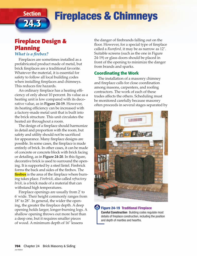
An ordinary fi replace has a heating effi -ciency of only about 10 percent. Its value as a heating unit is low compared with its deco-rative value, as in Figure 24-19. However, its heating effi ciency can be increased with a factory-made metal unit that is built into the brick structure. This unit circulates the heated air throughout a room.
The design of a fi replace should harmonize in detail and proportion with the room, but safety and utility should not be sacrifi ced for appearance. Many fi replace designs are possible. In some cases, the fi replace is made entirely of brick. In other cases, it can be made of concrete or concrete block with brick facing or detailing, as in Figure 24-20. In this fi gure, decorative brick is used to surround the open-ing. It is supported by a steel lintel. Firebrick forms the back and sides of the fi rebox. The fi rebox is the area of the fi replace where burn-ing takes place. Firebrick, also called refractory brick, is a brick made of a material that can withstand high temperatures.
Fireplace openings are usually from 2' to 6' wide. Their height commonly ranges from 18" to 28". In general, the wider the open-ing, the greater the fi replace depth. A deep opening holds larger, longer-burning logs. A shallow opening throws out more heat than a deep one, but it requires smaller pieces of wood. A minimum depth of 16" lessens
Fireplaces & Chimneys 24.3
the danger of fi rebrands falling out on the fl oor. However, for a special type of fi replace called a Rumford, it may be as narrow as 12". Suitable screens (such as the one in Figure 24-19) or glass doors should be placed in front of the opening to minimize the danger from brands and sparks.
Coordinating the WorkThe installation of a masonry chimney
and fi replace calls for close coordination among masons, carpenters, and roofi ng contractors. The work of each of these trades affects the others. Scheduling must be monitored carefully because masonry often proceeds in several stages separated by
Figure 24-19 Traditional FireplaceCareful Construction Building codes regulate most details of fi replace construction, including the position and depth of mantles and hearths.
704 Chapter 24 Brick Masonry & Siding Joe Mallon

Firebrick
Ash dump
Reinforcedconcrete slab
Depth
Hei
ght
Steel lintel
8"
8"
14"
Smoke shelf
Damper
Fireplaceflue liner
Furnaceflue liner
Wallframing
Header
Fronthearth
Floorframing
2" clearanceall sides
16" minimum
days or weeks. It is also affected by weather extremes. The various trades should contact each other directly and be cooperative. They should notify the general contractor or project supervisor when they have technical questions or scheduling problems that may affect the other trades.
Makeup AirCombustion requires a source of air. In
many cases, air for a fi replace is drawn from inside the house. That air is in turn replaced by outside air that is pulled in through gaps
and cracks. In cold weather, this means that heated household air is drawn up the chimney and replaced by cold outside air. In houses built to reduce air infi ltration, the fi re may not burn well because it cannot get enough air, and the chimney may smoke.
To reduce this problem, makeup air should be drawn into the fi rebox directly from outdoors. Makeup air replaces air exhausted by a combustion appliance. Most local codes now require that all types of fi replaces be supplied with makeup air. The makeup air passageway (sometimes called
Figure 24-20 Anatomy of a FireplaceConstruction Details Basic fi replace construction and framing details. The dimensions of the fi rebox determine its ability to function properly.
Section 24.3 Fireplaces & Chimneys 705

Regional Heating Though many houses have chimneys, fewer have fi replaces. They are least popular where the climate is mild. However, a masonry or prefabricated fi replace is common in cold climates and in cool, rainy climates, such as in the Northwest. In rural areas, a woodstove may provide all the heating needs of an entire house.
Go to glencoe.com for this book’s OLC for more information about regional concerns.
the fresh air intake) must have a cross section of at least 6 sq. in. and be covered with a cor-rosion-resistant screen. It may be located in the back or sides of the fi rebox, or within 24" of the fi rebox opening on or near the fl oor. It cannot be located in a basement or garage. The outlet must be closable. Be sure to check local codes for makeup air requirements.
Fireplace ConstructionDoes every fi replace need a hearth?
The relationships among the depth, height, and width of the fi rebox are impor-tant for proper operation of a fi replace. The cross-sectional size of the fl ue is also important. Building codes contain charts and graphs as an aid to fi replace design.
The main parts of a fi replace include the fi re-box, hearth, lintel and throat, damper, smoke shelf, and smoke chamber. Building codes regulate the relative sizes of these elements as well as their relationship to each other. The following information should serve as a general construction guide. However, always consult local codes prior to constructing a fi replace.
FireboxBuilding codes generally require that the
backs and sides of fi reboxes be constructed of solid masonry, stone, reinforced concrete, or hollow masonry units grouted solid. When lined with at least 2" of fi rebrick, the walls should be at least 8" thick. The fi rebrick must
be laid using refractory cement, with joints no greater than 1⁄4" wide. Refractory cement is a cement resistant to high temperatures.
HearthThe hearth is the fl oor of the fi rebox, plus
the fi reproof area in front of the fi replace. The hearth has two parts: the front hearth (sometimes called the hearth extension or the fi nish hearth) and the back hearth, under the fi re. Because the back hearth must withstand intense heat, it is built of or lined with fi re-brick. It should be at least 4" thick. The front hearth protects against fl ying sparks. While it must be noncombustible, it does not have to resist intense prolonged heat. It should be at least 2" thick.
If the fi replace opening is less than 6 sq. ft. in area, the front hearth should extend at least 16" in front of it and at least 8" on both sides. If the fi replace opening is 6 sq. ft. or more, the hearth should extend 20" in front of the opening and at least 12" to either side. However, always be sure to check local codes because they may require somewhat different dimensions.
The hearth can be fl ush with the fl oor or it can be raised. Raising and lengthening the hearth is presently common practice, especially in contemporary design. If there is a basement, a convenient ash dump can be built under the back of the hearth. (See Figure 24-20.)
In wood-framed buildings, the front and back hearths are sometimes supported by steel-reinforced concrete poured in place. If this method is used, any wood formwork must be removed after construction is complete. No combustible material can remain against the underside of the back or front hearths. One method of installing fl oor framing around the fi replace is shown in Figure 24-21.
Lintel and ThroatEvery standard masonry fi replace
includes a lintel. A lintel is a length of steel angle iron installed across the top of the fi re-box opening to support the masonry (Figure 24-20). It cannot be seen from the front of the fi replace. Angle iron measuring 1⁄4" thick
706 Chapter 24 Brick Masonry & Siding

Doubletrimmer
Subflooring
Joist
Subflooring
Hearth
2" min.
Doubleheader
and having 31⁄2" wide legs is commonly used. However, the actual dimensions depend on the width of the opening and the load to be supported.
Proper construction of the throat is essen-tial for a satisfactory fi replace, as shown in Figure 24-22. The throat is the narrowest part of the fi rebox, where the damper is located. The sides of the fi rebox must be vertical up to the throat, which should be 8" or more above the bottom of the lintel. The area of the throat must not be smaller than that of the fl ue.
DamperA damper consists of a cast iron frame
with a hinged lid. It opens or closes to vary the size of the throat opening (see Figure 24-20). In cold weather, closing the damper reduces heat loss when the chimney is not in use. In warm weather, a closed damper prevents insects and small animals from entering the house.
Dampers of various designs are available. However, it is important that the size of the damper opening equal the cross-sectional area of the fl ue.
Smoke Shelf and Smoke ChamberThe smoke shelf is on the back wall of the
smoke chamber. It helps to prevent down-drafts from driving smoke back down into the fi rebox (see Figure 24-20). It is made by
Figure 24-21 Floor Framing DetailsFire Prevention The framing details around this brick fi replace are designed to transfer loads around the opening.
Figure 24-22 Chimney Throat ConstructionCareful Detailing Approved installation details for the chimney throat and surrounding areas must be followed closely. This assures fi re safety and improves the draw of the fi replace and chimney.
Section 24.3 Fireplaces & Chimneys 707

MantelProjection (P)
Sectionthrough mantel
P =
1/8
"di
stan
cein
inch
es
Hearth
Surround
6" min.
6" min.
setting the brickwork at the top of the throat back to the line of the fl ue wall for the full length of the throat. The depth of the shelf may be 6" to 12" or more, depending on the depth of the fi replace. The smoke shelf is concave to hold any slight amount of rain that may enter.
The smoke chamber is the area from the top of the throat to the bottom of the fl ue. Its sidewalls slope inward to meet the fl ue, and its front is formed by corbeled bricks. To make the surfaces of the smoke shelf and the smoke chamber walls smooth, they should be plastered with cement mortar at least 1⁄2" thick. If corbelled gradually, the chamber walls can be plastered with refractory cement that can be sponged smooth. This seals any voids in the walls and reduces the amount of creosote buildup on the walls.
ClearancesIt is the front, or surround, of a fi replace
that can have the greatest effect on the architectural style of a room. Many different materials can be used. These include brick, ceramic tile, wood molding and trim, and wood mantels. However, any combustible material must be installed with care and according to building codes, as shown in Figure 24-23. Use the following guidelines:• No woodwork can be placed within 6" of
the fi rebox opening.
• Woodwork, including any mantel located between 6" and 12" from the fi rebox opening, must not project forward more than 1⁄8" for every inch above the opening. For example, a mantel located 9" above the fi rebox opening can be no more than 11⁄8" wide (9 � 1⁄8" � 11⁄8").
Figure 24-23 Clearance to WoodMimimum Clearances Maintaining a suitable distance between combustible trim and the fi replace opening helps to prevent trim from overheating.
708 Chapter 24 Brick Masonry & Siding

Heatoutlet
Heat outlet register
Airinlet
Prefabricated FireplacesSome fi replaces are made with a heavy-
gauge metal fi rebox. Some of these are designed to be concealed by brickwork or other materials, as shown in Figure 24-24. Others can be set into a wood-framed open-ing and connected to a prefabricated metal chimney system. In either case, a prefab-ricated fi replace includes all the essential parts: fi rebox, damper, throat, smoke shelf, and smoke chamber. The correctly designed and proportioned fi rebox provides a ready-made form for masonry. This reduces the chance of faulty construction.
Recall Why is the back hearth built or lined with fi rebrick?
Chimney Design & PlanningWhat design problems would a cylindrical chimney create?
Just as with fi replaces, chimneys may be built of various materials but brick is a popular choice. It is essential for safety to follow all local building codes when install-ing chimneys. This reduces fi re hazards and ensures that dangerous combustion gases are not released into the house.
A chimney is required for any fuel-burning appliance, such as a fi replace, wood stove, or furnace. The purpose of a chimney is to produce suffi cient draft. Draft is the upward movement of air within the chimney. Draft draws air into the appliance. This aids in combustion (burning) and expels smoke and harmful gases. The greater the difference in temperature between chimney gases and the outside air, the stronger the draft. An interior chimney will usually have a better draft than an exterior chimney of the same height because it is better able to retain heat.
Chimneys are generally constructed of brick or other masonry units supported by a concrete slab foundation. However, lightweight metal chimneys can be used when approved by local building codes. The design of a chimney is very important for its safety and effectiveness. It may be well constructed, but if it is not designed properly it will not work well. The following information is meant only as a general guide. Always consult local building codes.
Flue SizeThe fl ue is the passage inside the chimney
through which the air, gases, and smoke rise. Its dimensions, height, shape, and interior smooth-ness determine how effective the chimney is in creating enough draft. When a fuel-burning unit is connected to a chimney, consult the unit’s specifi cations to establish the fl ue size.
HeightThe height of a chimney above the roofl ine
is usually based on its location in relation to the ridge. On a pitched roof, the top of the
Figure 24-24 Prefabricated FireboxEffi cient Heater Air from the room is drawn through the air inlet. The air is heated upon contact with the metal and discharged through the heat outlet.
Section 24.3 Fireplaces & Chimneys 709

Top offlue lining
2' minimum
Ridge
Flue lining
Framing
Incombustiblematerial
2" gap minimum
fl ue lining should be at least 2' above any portion of the roof that is within 10' (measured horizontally) of the chimney, as shown in Figure 24-25. One reason for this is to ensure that burning embers leaving the chimney will cool before they can ignite roofi ng materials. Another reason is to encourage proper draft. A chimney shielded from the wind by a nearby ridge may not draw well.
In addition, codes may require that the top of the chimney be above any operable window within a 20' radius. This helps to prevent smoke from being drawn into the house when the window is open.
Earthquake ProtectionIn many areas, chimneys need little
in the way of reinforcement. However, where earthquake activity is a serious risk, building codes require masonry chimneys to be reinforced vertically and horizontally. The exact size and type of reinforcement depend on the size of the chimney and local codes. However, chimneys up to 40" wide must contain at least four continuous lengths of No. 4 reinforcing bar. Horizontal reinforcements must be located no farther apart than every 18" along the height of the chimney.
In addition, a masonry chimney located outside the house walls must be anchored to the framing. This must be done with two 3⁄16" � 1" metal straps at each fl oor, ceiling, and roofl ine that is more than 6' above grade. The straps should be bolted to framing with 1⁄2" diameter bolts. These reinforcement details are not required if the chimney is located completely within the exterior walls.
ClearancesAny portion of a chimney located within
the house must have a 2" clearance between its walls and the wood framing, as shown in Figure 24-26. Subfl ooring and fi nish fl oor-ing can be laid within 3⁄4" of the masonry. If the chimney is located entirely outside the exterior walls, the gap must be at least 1". Exterior wood sheathing, siding, and trim can touch the side walls of the chimney, but only where they will be at least 12" from the nearest fl ue liner.
The space between wall and fl oor framing must be fi lled with a code-approved fi re-stopping material. This prevents shavings or
Figure 24-25 Chimney HeightA Safe Height The top of the fl ue lining should be at least 2' above the ridge.
Figure 24-26 Clearance to FramingHeat Shield Wood fl oor joists must be protected from chimney heat with a suitable fi re-stopping product.
710 Chapter 24 Brick Masonry & Siding

Cleanoutdoor
Ash dump
4'-0"
2'-6" Back hearth
2" air gapbetweenchimney andwood framing
Firebrick
Dampercontrol
Damper
Smokechamber
Smokeshelf
Basement floor
Chimney foundation
Chimneywall
8"2' minimum
Cap
Flue liner
Front hearth
Heatingunit flue
Fireplaceflue
Concretehearth support
Firebox(fireplace)
3'-0"
6'-0"
other fl ammable material from building up in these areas. It also keeps combustible materials away from the masonry. Several types of materials may be used, including mineral wool. Unbacked fi berglass insula-tion is not recommended. Brickwork or standard mortar should not be used because they conduct heat. Fire-stopping materials should be added before the fl oor sheathing is installed.
Chimney Construction DetailsThe main parts of a chimney include the
foundation, fl ue liners, walls, and cleanout opening.
Foundation The chimney is usually the heaviest part of a building. It must rest on a foundation and footings to prevent uneven settling and to avoid exceeding the load-bearing capacity of the soil. The foundation is usually built at the same time as the house foundation walls. It must extend at least 6" beyond the chimney on all sides and be at least 12" thick, as shown in Figure 24-27. Steel reinforcement should be added as required by local codes.Flue Liners Building code now requires that all chimneys be lined during installation. A separate fl ue and fl ue liner is needed for each fi replace, furnace, and boiler. A fl ue liner
Figure 24-27 Anatomy of a ChimneyDual Use This chimney is designed to exhaust gases from the furnace and from one fi replace.
Section 24.3 Fireplaces & Chimneys 711

Wall coveringWythe
2"
2"
Groupedflue liners
is a fi re-clay or stainless-steel pipe assembled from individual sections that sit within the chimney brickwork. Without a liner, mortar and bricks directly exposed to heat and fl ue gases can crack. This creates a fi re hazard.
Rectangular fi re-clay fl ue liners or round glazed (vitrifi ed) tile can normally be used in all chimneys. Glazed tile or a stainless steel liner is usually required for gas-burning equipment. Local codes outline specifi c requirements.
Each length of fi re-clay or glazed-tile liner should be set in refractory cement with the joint struck smooth on the inside. The liner and brick are installed together as the chimney is built. In masonry chimneys with walls less than 8" thick, there should be an air space between the liner and the chimney walls. This allows for expansion and contrac-tion, and improves heat dissipation. This space should not be blocked by mortar.
The fl ue liner above a fi replace starts at the top of the throat and extends to the top of the chimney. If a chimney contains three or more lined fl ues, each group of two must be separated from the others by a layer of brick called a wythe, as seen in Figure 24-28. Joints in the liners of two fl ues grouped together without a wythe between them should be staggered at least 7".
Chimney WallsWalls of masonry chimneys must have a
nominal thickness of at least 4", not includ-ing the lining. This is about the width of one brick. Greater thickness may be required if the chimney is unusually tall or located in an earthquake zone.
To strengthen the exposed portion of an interior chimney, the bricks are sometimes corbeled in the portion around the roofl ine. A corbel is a course of brick offset to extend past the course below it, as shown in Figure 24-29. A corbel must not project more than one-half the height of the brick or one-third the width of the mortar bed depth, whichever is less. The top of a chimney is also sometimes corbeled, though this is done purely for decoration. Corbeling can
be used to alter the position of a chimney, as when avoiding framing that cannot be relocated. Local codes may specify other requirements.
The chimney wall and its fl ue liner must not change dimension within 6" above or below where the chimney passes through a fl oor, ceiling, or roof assembly. This reduces the risk of leaving gaps in the masonry that might allow sparks to reach the framing.Joints Brickwork around chimney fl ues and fi replaces should be laid with cement mortar. It is more resistant to the action of heat and fl ue gases than lime mortar. All bricks and blocks require full, push-fi lled mortar joints having no gaps anywhere. A push-fi lled joint is one created by pushing the brick into a thick bed of mortar and then striking off the excess that squeezes out.
Cleanout OpeningSoot and ash that build up in a chimney
can be removed through a small cleanout (see Figure 24-27). A cleanout is required within 6" of the base of each fl ue. A single cleanout should serve only one fl ue. If two or more fl ues are connected to the same clean-out, air drawn from one to the other will
Figure 24-28 Three-Flue ChimneyPlan View The joints of successive courses of brick should be staggered. This strengthens the chimney. Wood framing should be at least 2" from the masonry.
712 Chapter 24 Brick Masonry & Siding

Corbeling
Flue liner
Flashing
Saddle
6" min.
Cut lining fortight joint
Corbeling
Flue liner
Upper flue linercenterline
affect the draft in all the fl ues. The cast-iron door on the cleanout should fi t snugly and be kept tightly closed to keep air out.
Summarize Why must the chimney rest on a foundation and footings?
Roof DetailsCare must be taken where the chimney
meets the roofi ng system. The area must resist heat from the chimney, but it must also resist water leakage. Wood and masonry expand and contract at different rates, so construction must allow for this movement.At the Roof Where any portion of the chim-ney is located within the exterior walls, a
A
B
Figure 24-29 CorbelingChanging Size or Direction A. Corbeling (offsetting the bricks) to provide a larger chimney above the roof line. B. Offsetting a chimney. For structural safety, the centerline of the upper fl ue should not fall beyond the center of the lower chimney wall.
Working on a Roof When completing the top of a chimney, work from scaffolding whenever possible. This is safer than trying to work standing on the roof itself. Scaffolding offers a fl at, stable surface from which tools and materials will not slide. It is also a more comfortable surface from which to work.
Go to glencoe.com for this book’s OLC for more on job safety.
2" clearance is required between the masonry and any wood framing or sheath-ing. This is done to reduce fi re hazards. However, if the chimney is entirely outside the exterior walls, the minimum clearance is reduced to 1". This clearance also permits expansion due to temperature changes, set-tling, and slight movement of the chimney during heavy winds.
Section 24.3 Fireplaces & Chimneys 713

Flue liner
Concretecap
Face of chimney(high side)
Level
Roofsheathing
Chimney width
Saddle
A
B
6" minimum
Saddle height
Caulk cap flashing 1" or more intomasonry joint
4" minimum for slopes5-in-12 and over, and 3"minimum forslopes under 5-in-12
Flashingbent into joint
Capflashing
Baseflashing
Jointsoldered
Ridgecap
Figure 24-31 Special Flashing DetailsPreventing Leaks Flashing a chimney that rises through a sloped roof. A. A narrow chimney where no saddle is required. B. A wide chimney with a saddle.
Figure 24-32 Chimney CapDecorative and Functional A cap prevents water from seeping between the chimney walls and the fl ue.
Chimneys must be fl ashed and counter-fl ashed to make the junction with the roof watertight, as shown in Figure 24-30. Corrosion-resistant metal, such as copper, galvanized steel, or lead-coated copper, should be used for fl ashing.
When a chimney rises through a sloped roof, careful detailing is required to prevent water fl owing down the roof from causing leaks at the chimney. There are two methods for handling this detail. Overlapping Flashing Cap fl ashing embedded in the chimney mortar joints overlaps a wide piece of base fl ashing on the roof, as in Figure 24-31A.Chimney Saddle A saddle (sometimes called a chimney cricket) actually diverts water around the chimney, as in Figure 24-31B. Building code requires a saddle when the chimney dimension parallel to the ridge line is greater than 30" and does not intersect the ridge. For installation information, see Section 19.3.
Above the Roof A mortar or precast concrete cap should be placed over the top course of brick to prevent moisture from seeping between the brick and fl ue liner, as shown in Figure 24-32. The cap should be sloped away from the fl ues on all sides to drain water away. The fl ue liner should extend at least 4" above the top course of brick. Any gaps between the fl ue liner and the cap should be sealed with mortar.
Figure 24-30 Chimney FlashingWater Blocker A chimney located on a ridge calls for cap fl ashing that fi ts over base fl ashing.
714 Chapter 24 Brick Masonry & Siding
Stone orconcretecap
1/2" min. meshwoven wirescreen, galv.
Stone orconcrete cap
Wythe
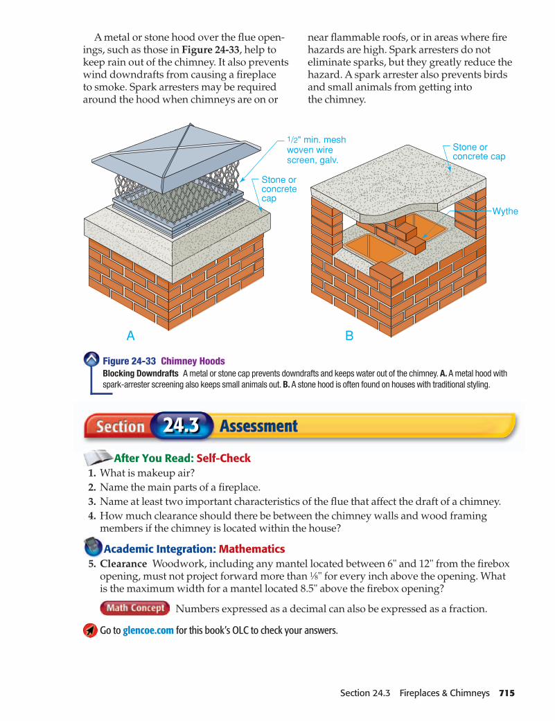
A metal or stone hood over the fl ue open-ings, such as those in Figure 24-33, help to keep rain out of the chimney. It also prevents wind downdrafts from causing a fi replace to smoke. Spark arresters may be required around the hood when chimneys are on or
near fl ammable roofs, or in areas where fi re hazards are high. Spark arresters do not eliminate sparks, but they greatly reduce the hazard. A spark arrester also prevents birds and small animals from getting into the chimney.
Figure 24-33 Chimney HoodsBlocking Downdrafts A metal or stone cap prevents downdrafts and keeps water out of the chimney. A. A metal hood with spark-arrester screening also keeps small animals out. B. A stone hood is often found on houses with traditional styling.
A
After You Read: Self-Check 1. What is makeup air? 2. Name the main parts of a fi replace. 3. Name at least two important characteristics of the fl ue that affect the draft of a chimney. 4. How much clearance should there be between the chimney walls and wood framing
members if the chimney is located within the house?
Academic Integration: Mathematics 5. Clearance Woodwork, including any mantel located between 6" and 12" from the fi rebox
opening, must not project forward more than 1⁄8" for every inch above the opening. What is the maximum width for a mantel located 8.5" above the fi rebox opening?
Numbers expressed as a decimal can also be expressed as a fraction.
Go to glencoe.com for this book’s OLC to check your answers.
24.3
B
Section 24.3 Fireplaces & Chimneys 715

24
Review Content Vocabulary and Academic Vocabulary 1. Use each of these content vocabulary and academic vocabulary words in a sentence or diagram.
Content Vocabulary• jointer (p. 688)• retempering (p. 694)• weep hole (p. 698)• lintel (p. 699)• lead corner (p. 699)
• line block (p. 701)• fi rebox (p. 704)• makeup air (p. 705)• refractory cement (p. 706)• hearth (p. 706)
Academic Vocabulary• initial (p. 694)• transmission (p. 696)• prolonged (p. 706)
Like a ProTechnical Terms 2. Work with a classmate to defi ne the follow-
ing terms used in the chapter: brick trowel (p. 688), mason’s rule (p. 688), brick tongs (p. 689), brick hammer (p. 689), brick set (p. 690), frog (p. 691), wall ties (p. 698), damper (p. 707), smoke shelf (p. 707), smoke chamber (p. 708), surround (p. 708), fl ue liner (p. 711), wythe (p. 712), push-fi lled joint (p. 712), saddle (p. 714).
Review Key Concepts 3. Name three tools used in working with
brick and mixing mortar.
4. List the steps in cutting brick with a mason’s hammer.
5. Identify the type of mortar used most often for brick veneer.
6. Describe how cold may affect laying out brick.
7. List the main parts of a chimney.
8. List the main parts of a fi replace.
Review and Assessment
24.1
Chapter SummaryImportant brick-laying tools include the brick trowel and the jointer. Brick comes in three main types: building brick, facing brick and fi re brick. The four types of mortar are M, S, N, and O. Mortar may be mixed by hand or by machine.
Weep holes provide drainage for veneer walls. Wall ties secure the wall to the framing. Line blocks and corner poles help masons align courses. A wall is begun at the corners. Joints are tooled for strength and appearance.
Chimneys may be made of masonry or prefabricated parts. It is extremely important to construct a chimney so that it does not create a fi re hazard. Height above the roofl ine and clearance to wood framing must be considered. A chimney saddle diverts water around the chimney. A cap keeps moisture from seeping between the brick and the fl ue. The interior portions of a masonry fi replace must be properly designed and carefully constructed. This ensures proper working of the fi replace. It also ensures that smoke and harmful gases are drawn out of the house effi ciently. The main parts of a fi replace include the fi rebox, damper, throat, lintel, smoke shelf, smoke chamber, and hearth.
24.2
Section
Section
24.3Section
• draft (p. 709)• fl ue (p. 709)• corbel (p. 712)
716 Chapter 24 Review and Assessment

Critical Thinking 9. Summarize What may happen if building
codes for installing masonry in the cold are not followed properly?
Academic and Workplace Applications
10. Using Standard Units If a fi replace open-ing is less than 6 sq. ft. in area, the front hearth should extend at least 16" in front of it and at least 8" on both sides. If the fi re-place opening is 6 sq. ft. or more, the hearth should extend 20" in front of the opening and at least 12" to either side. What is the minimum area of a front hearth for a fi re-place that is 40" wide and 30" tall?
When solving a measure-ment problem, convert all measurements to the same units.
Step 1: Determine the area of the fi replace opening in square feet.
Step 2: Determine the length and width of the front hearth.
Step 3: Calculate the area.
11. Heating Effi ciency Describe the heating effi ciency of a traditional fi replace. Then describe some ways in which you could improve its heating effi ciency in order to fulfi ll your architectural desires, as well as your heating needs. Your description should be no more than one page and can include lists, diagrams, or bullets.
12. Communication Skills You are the fore-man on a masonry project. You have just hired an inexperienced laborer to help com-plete the job. You have noticed that he is using a tape measure to measure the height and spacing of brick courses. Write a short paragraph explaining how you could explain to the laborer that a mason’s rule would be better suited for this purpose. Explain what a mason’s rule is and why this tool is better for this particular job than a tape measure is.
Short AnswerDirections Write one or two sentences to answer the following questions. Use complete sentences.
13. What is a struck joint?
14. How are weep holes formed?
15. How is a brick hammer used to cut brick?
Before answering short-answer questions, write down key words or phrases from the material you remember before writing your sentences. Make sure your complete sentences include both a subject and a predicate.
* These questions will help you practice for nationalcertifi cation assessment.
Chapter 24 Review and Assessment 717

Your Project AssignmentFor a weekend volunteer project, you will design and
assemble a storage shed. The shed will have a simple gable roof with a 4-in-12 slope. The exterior will have vinyl siding. Before you begin, you need to estimate and price all the materials you will need for the project.
• Find a local organization, such as Rebuilding Together, that builds or repairs homes for low-income members of the community.
• Specify the dimensions and materials for a rectangular storage shed that could be part of one of the organization’s building projects.
• Calculate the quantity of materials required for the shed.
• Create a three- to fi ve-minute presentation.
Applied SkillsSome skills you might use include:
• Defi ne the dimensions for a shed based on its location and intended use.
• Compare shed materials and specify which one best fi ts your needs.
• Research the steps in building a shed.
• Calculate the total materials and costs for your project.
• Identify the amount of labor involved in building the shed.
Measurement: Understand measurable attributes of objects and the units, systems, and processes of measurement
Measurement: Apply appropriate techniques, tools, and formulas to determine measurements
Geometry: Analyze characteristics and properties of two- and three-dimensional geometric shapes and develop mathemati-cal arguments about geometric relationships
NCTM National Council of Teachers of Mathematics
The Math Behind the ProjectThe traditional math skills for this project are estima-
tion and geometry. Remember these key concepts:
EstimationMany construction materials, such as vinyl siding,
come in standard sizes. To estimate how much of these materials you will need, fi rst calculate the amount of the material you will need for the project. Then divide this total by the standard size of the material. For example, if your exterior walls measure 250 square feet and 12 pieces of 8' vinyl siding covers 100 square feet, you will need 30 pieces of siding.
GeometryA 4-in-12 gable roof has 4 inches of rise for every
12 inches of run. To calculate the rise of a 4-in-12 gable roof, fi rst divide the span in half to fi nd the run. Then multiply the run by 4" to fi nd the rise. Once you know the run and the rise, you can use the Pythagorean theorem to calculate the rafter length.
For example, if your shed is 8 feet wide, to fi nd the run, rise, and rafter length, use the following steps:
UNIT 5Hands-On Math Project
Assembling Resources
718 Unit 5 Completing the Structure
1. Divide the span by two to fi nd the run. 8' � 2 � 4'
2. Multiply the run by 4" to fi nd the rise. 4 � 4" � 16"
3. Convert the run from feet to inches. 4 � 12 � 48"
4. Use the Pythagorean theorem to calculate the rafter length. Round the result.
√(16)2 + (48)2 = 50.6"

Project Steps
Research
• Find a local organization that provides repairs or builds homes for members of the community.
• Contact your organization to fi nd out the size, materials, and likely use of a shed that would be most suitable for its building projects.
• Compare the costs of various shed materials such as redwood lumber and enamel-coated steel.
• Research the steps involved in building a shed.
• Investigate what building permits may be required for a new shed.
Plan
• Determine the main use for your shed. Sketch a suitable plan, labeling dimensions and indicating the placement and size of the door.
• Calculate the run, rise, and rafter length of the roof.
• Calculate total square footage of siding and roof materials.
• Estimate how long it will take to build the shed, working either alone or in a team.
Apply
• Use your plan and measurements to calculate how much wall and roof material, siding, paint, and other materials you will need to build the shed.
• Create a quantity take-off for the project.
• Calculate the total cost of building the shed.
Go to glencoe.com for this book’s OLC to read an article titled “Vinyl By Design” to learn more about vinyl as a building material. Write a summary of this article.
PRESENTATION CHECKLISTDid you remember to…
✓ Explain and describe your shed design?
✓ Demonstrate how you calculated the run, rise, and rafter length of the roof?
✓ Include costs for all materials needed to build the shed?
✓ Describe the basic steps in assembling the shed?
✓ Use a standard format for your quantity take-off?
Technical and Academic Evaluation
Assess yourself before and after your presentation.
1. Did you choose a realistic and practical shed design?2. Was your research thorough?3. Were your cost estimates accurate and realistic?4. Were your measurements and calculations accurate?5. Was your presentation creative and effective?
Go to glencoe.com for this book’s OLC for an evaluation rubric and the Academic assessment for this project.
Rebuilding TogetherMission: To bring volunteers and communities together to improve the homes and lives of low-income homeowners by providing free repair services for those with the greatest need.
Go to glencoe.com for this book’s OLC for more information on this organization.
Present
Prepare a presentation that describes your research, presents your design, and explains your cost calculations using the checklist below.
Unit 5 Completing the Structure 719