bridge design memorandum - nh.gov of new hampshire 1 of 2 bridge design memorandum from: l. robert...
TRANSCRIPT

STATE OF NEW HAMPSHIRE 1 of 2 BRIDGE DESIGN MEMORANDUM
FROM: L. Robert Landry, Jr., PE DATE: October 27, 2017
Administrator AT (Office): Bureau of Bridge Design
SUBJECT: Design Memorandum 2017-01
LRFD Design for Overhead Sign Structures, Structural Supports for CCTV cameras,
RWIS, and Non-invasive Pavement Sensor Systems, and their Foundations
Straight Anchor Rods for Foundations
TO: Bureau of Bridge Design Staff, Bridge Design Consultants, FHWA, and NHDOT Bureaus
The Bureau of Bridge Design is updating the Bridge Design Manual. During this process, certain
design decisions are being issued for immediate implementation. Consequently, the Bridge Design Manual
and Traffic Detail Sheets have been modified as follows:
A. Bridge Design Manual:
• Chapter 10, Section 10.2, 10.3, 10.6, and References
• Appendix 10.2-A1
B. Traffic Detail Sheets:
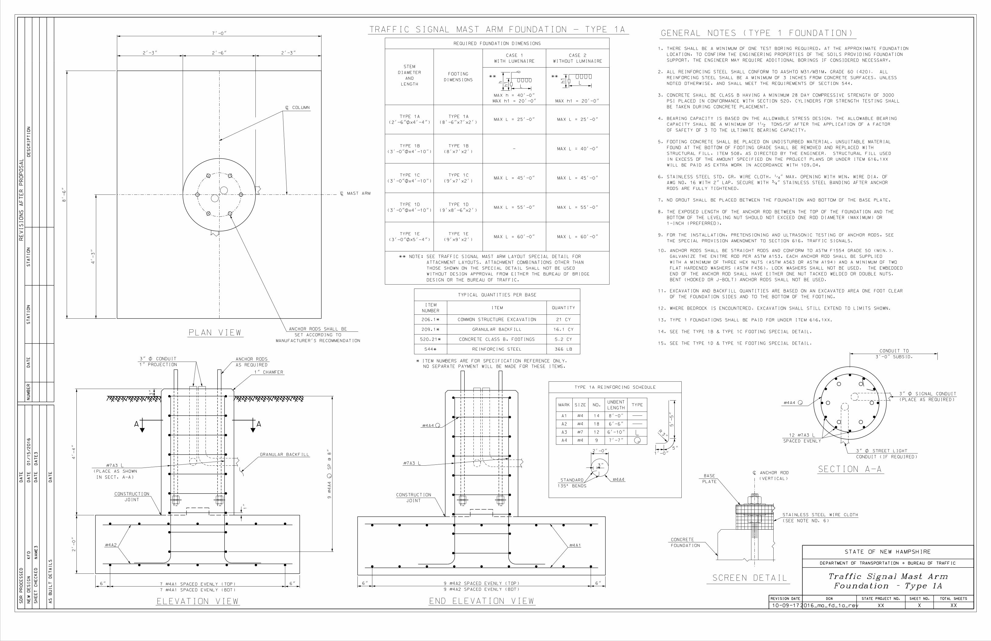
• Traffic Signal Mast Arm Foundation – Type 1A
• Traffic Signal Mast Arm Foundation – Type 1B & 1C
• Traffic Signal Mast Arm Foundation – Type 1D & 1E
• Traffic Signal Mast Arm Foundation – Type 2
C. Summary: The above noted revisions are being implemented to specify the following:
• NHDOT is implementing that all overhead sign structures, CCTV poles, RWIS and non-
invasive pavement sensor system supports, and their foundations be designed in accordance
with the current AASHTO LRFD Specifications for Structural Supports for Highway Signs,
Luminaires, and Traffic Signals.
• Traffic signal mast arms, luminaire poles, high-mast lighting poles, roadside signs, their
foundations, and bridge-mounted sign supports shall be designed in accordance with AASHTO
Standard Specifications for Structural Supports for Highway Signs, Luminaires, and Traffic
Signals.
• NHDOT is implementing that all foundation anchor rods for overhead sign structures, CCTV
poles, RWIS, non-invasive pavement sensor systems, traffic signal mast arms, luminaire poles,
and high-mast lighting poles shall be straight rods conforming to the requirements of ASTM
F1554 Grade 55 (minimum). ASTM A615 reinforcing steel is not permitted. Galvanize the
entire anchor rod per ASTM A153. Each anchor rod shall be supplied with a minimum of three
hex nuts (ASTM A563 or ASTM A194) and a minimum of two flat hardened washers (ASTM
F436). Bent (hooked or J-bolt) anchor rods shall not be used.
• The special provisions have been revised for these implementations.
• The Traffic Detail Sheets (.dgn and .pdf format) have been revised and are located on the
Bureau of Highway Design Detail Sheets web page:
https://www.nh.gov/dot/org/projectdevelopment/highwaydesign/detailsheets/index.htm


Chapter 10 Non-Bridge Structures
NHDOT Bridge Design Manual v2.0 Page 10.2-1 January 2015
Revised October 2017
10.2 Loads
A. General
Overhead sign structures, intelligent transportation systems (CCTV, Road and Weather Information Station Systems, and Non-Invasive Pavement Sensor Systems), and the foundations shall be designed in accordance with the current edition of AASHTO LRFD Specifications for Structural Supports for Highway Signs, Luminaires, and Traffic Signals, including interims, ASCE/SEI 7 Minimum Design Loads For Buildings and other Structures, NHDOT Standard Specifications for Road and Bridge Construction, NHDOT Bridge Design Manual, and any special provisions. Traffic signal mast arms, luminaire poles, high mast lighting poles, and bridge-mounted sign supports shall be designed in accordance with AASHTO Standard Specifications for Structural Supports for Highway Signs, Luminaires, and Traffic Signals, including interims.
B. Dead Loads
• Sign (Incl. weight of sign & attachments (3 psf [14.6 kg/m2]) and 5.0 psf (24.4 kg/m2)
weight of W6x9 sign support (typically avg. 2 psf [9.8 kg/m2]) • Dynamic Message Sign (DMS) per manufacturer • Variable Speed Limit Sign (VSLS) per manufacturer • Luminaire per manufacturer • Standard Signal Head per manufacturer • Bridge Mounted Sign Supports calculate • Structural Members calculate • Maintenance Walkway per manufacturer • Closed Circuit Television per manufacturer
C. Wind Loads
• The 3-second wind gust map in the AASHTO LRFD Specifications for Structural Supports for Highway Signs, Luminaires, and Traffic Signals shows the basic wind speed to be used when computing design wind pressure.
• 1700-year MRI basic wind speed of 130-mph (209-km/hr) shall be used for the entire state of NH except in the Special Wind Region (i.e. regions along the NH-VT border and Franconia Notch) as shown in AASHTO LRFD Specifications, Fig. 3.8-2b. The maximum-recorded wind speed in this area shall be used as the basic wind speed if it is greater than the NH basic wind speed of 130-mph (209-km/hr). See the special wind region map located at http://www.windspeedbyzip.com/, Appendix 10.2-A1, and weather stations in the special wind region for recorded wind speeds.
D. Mean Recurrence Interval (Table 3.8-1 AASHTO LRFD Specifications for Structural Supports for Highway Signs, Luminaires, and Traffic Signals)
• Risk Category: Typical, 1700-year MRI
E. Ice Loads (Applied to a DMS or VSLS only)
• Applied to the top, ends, and front face.
• Ice load per ASCE 7, Chapter 10. Factored load combinations using Strength Design per ASCE 7, Section 2.3.2 and 2.3.4.

Chapter 10 Non-Bridge Structures
NHDOT Bridge Design Manual v2.0 Page 10.2-2 January 2015
Revised October 2017
F. Snow Loads (Applied to a DMS or VSLS only)
• Applied to the top panel and any other horizontal projection of a DMS or VSLS. • Ground snow load (pg) taken at a specific elevation and location in New Hampshire as
noted in US Army Corps of Engineers Ground Snow Loads for NH (February 2002), Table 1. Reduce or increase value for the design elevation as noted in footnote.
• Use flat roof snow load (pf) per equation 7.3-1 in ASCE 7. • Use load combinations with Strength Design per ASCE 7, Section 2.3.2 and 2.3.4.
G. Fatigue Design
Fatigue design shall conform to AASHTO LRFD Specifications for Structural Supports for Highway Signs, Luminaires, and Traffic Signals and the following categories:
1) Cantilevered Fatigue Category I: • All overhead cantilever sign structures
⇒ Galloping loads may be excluded for fatigue design of overhead cantilevered sign structures with four-chord horizontal trusses.
• ITS support poles (horizontal distance from roadway to pole ≤ height of pole)
2) Cantilevered Fatigue Category II: • ITS support poles (horizontal distance from roadway to pole > height of pole)
3) Non-Cantilevered Fatigue Category I: • Overhead bridge sign structures located along the Turnpike, Interstate, and
Interstate ramps
4) Non-Cantilevered Fatigue Category II: • Overhead bridge sign structures located on non-Turnpike, non-Interstate, NH,
and US numbered routes
H. Live Load:
• A live load consisting of a single load of 500-lbs. (226.8-kg) distributed over 2.0-ft. (0.6-m) transversely to the member shall be used for designing members for walkways and platforms (AASHTO LRFD Specifications for Structural Supports for Highway Signs, Luminaires, and Traffic Signals, Section 3.6).
Support structures shall be designed using the maximum of the load combinations noted in AASHTO LRFD Specifications for Structural Supports for Highway Signs, Luminaires, and Traffic Signals, Section 3.4 and Table 3.4-1 and ASCE 7 (ice and snow loads).

Chapter 10 Non-Bridge Structures
NHDOT Bridge Design Manual v2.0 Page 10.3-1 January 2015
Revised October 2017
10.3 Overhead Sign Structures
10.3.1 General
The design of overhead sign structures is a combined effort between the Bureau of Bridge Design and the supplier of the structure. Bridge Design is responsible for the preliminary and final design of the foundations for overhead sign structures for In-House projects. Consultants are responsible for the preliminary and final design of the foundations, with the guidance from Bridge Design, for Consultant projects. The supplier of overhead sign structures is responsible for the design of the structure and submits shop drawings to the Department for approval. The supplier’s calculations and shop plans are reviewed for general conformity with Contract Plans and NHDOT’s policies and specifications.
10.3.2 NHDOT Design Requirements
A. Structure • Overhead sign structures shall be designed to accommodate sign surface areas 30 percent
greater than those shown on the plans, unless otherwise noted. • The structures shall be galvanized steel in accordance with NHDOT Specification
550.2.9. • Provide a 3-foot (1-meter) walkway with OSHA approved railing for access to any
electronic message signs on overhead structures. The walkway shall extend to the edge of pavement to provide access to the DMS without having to use a bucket truck over the travel lane, or having to shut down travel lanes.
• The structure shop plans and calculations shall be prepared and stamped by a professional engineer licensed in the state of New Hampshire.
• 25 percent of the base plate-to-post weld shall be inspected by magnetic particle testing per AASHTO Specifications. This requirement shall be noted on the shop plans.
• Sign support members (W6x9) shall not be greater in length than the sign height. • The Fabricator shall furnish a complete set of shop drawings and design calculations,
along with the design forces and offsets, as noted in Special Provision Amendment to Section 615, Traffic Signs.
• The connection of the structure to the foundation shall be a double-nut moment connection.
• Lock washers shall not be used with the installation of high strength bolts per FHWA Guidelines.
• Triangular truss and tubular arch type overhead sign structures, as shown below, are not permitted due to concerns with their susceptibility to fatigue cracking.

Chapter 10 Non-Bridge Structures
NHDOT Bridge Design Manual v2.0 Page 10.3-2 January 2015
Revised October 2017
• NHDOT permitted sign structure types include the following (see Figure 10.3.2-1): 1) truss upright, truss horizontal 2) monotube upright, truss horizontal 3) monotube upright, monotube horizontal
NHDOT Sign Structure Types
Figure 10.3.2-1
monotube upright, truss horizontal
truss upright, truss horizontal
monotube upright, monotube horizontal
truss upright, truss horizontal

Chapter 10 Non-Bridge Structures
NHDOT Bridge Design Manual v2.0 Page 10.3-3 January 2015
Revised October 2017
B. Foundation • Spread footing foundations shall be used for all sign structures, unless directed otherwise
by the Geotechnical Engineer. • NHDOT policy for maximum allowed area of footing with uplift shall be the following:
⇒ Sign bridge structure = 5 % of footing area. ⇒ Cantilevered sign structure = 1 % of footing area.
• Use the same reinforcing bar size for both directions in the footing. • The vertical stem reinforcing bars shall be checked for development length, into both the
stem and footing. • The overlap length of the vertical reinforcing bar and anchor rod shall be checked that the
length is equivalent to a class c splice of the reinforcing bar. • The distance from the top of the concrete stem to the bottom of the sign structure base
plate shall equal the nut height plus 1-inch (25-mm) (preferred) or nut height plus the anchor rod diameter (maximum). (Note the nut height equals the rod diameter.)
• Anchor rods shall be straight double headed rods and conform to the requirements of ASTM F1554 Grade 55 (minimum). ASTM A615 reinforcing steel is not permitted. Galvanize the entire anchor rod per ASTM A153. Each anchor rod shall be supplied with a minimum of three hex nuts (ASTM A563 or ASTM A194) and a minimum of two flat hardened washers (ASTM F436). Bent (hooked or J-bolt) anchor rods shall not be used.
• Anchor rods shall include hardened washers. Lock washers shall not be used as they do not prevent loss of the anchor bolt preload, and their variability of deformation under load does not provide for proper bolt tension during installation.
• Anchor rod size and layout shall be designed by the structure Fabricator and shall be identical for both left and right footings.
• For sign structures that are designed for Cantilevered Fatigue Category I, the anchor rods shall be designed for wind-induced cyclic loads per AASHTO Standard Specifications for Structural Supports for Highway Signs, Luminaires, and Traffic Signals, 5.17.3.4.
• Each monotube upright post shall have a minimum of eight (8) foundation anchor rods. Each post of a multi post upright (truss) shall have a minimum of four (4) foundation anchor rods per post.
• The connection of the structure to the foundation shall be a double-nut moment connection.
• Grout shall not be used between the structure base plate and the top of the footing. The grout on existing footings has cracked, allowing water and chlorides to stay in the cracks and not dry out, which has led to corrosion of the anchor rods.
• A stainless steel standard grade wire cloth (1/4-in. (6.4 mm) maximum opening with minimum wire diameter of AWG No. 16) shall be installed around the structure base plate and top of footing with a 2-inch (51 mm) lap as shown and noted on the footing plans. The screen is to prevent debris from collecting beneath the base plate, keep animals out, and protect the electrical wires.
• Typical NHDOT sign footing plan is shown in Appendix 10.3-B1. • Cofferdams, Item 503.20x may be required if there is insufficient room to excavate for
the footing using 1.5:1 cut slopes. Cofferdams with Sheeting Left-in-Place, Item 503.30x, should be used when its removal would create a stability problem with adjacent

Chapter 10 Non-Bridge Structures
NHDOT Bridge Design Manual v2.0 Page 10.3-4 January 2015
Revised October 2017
structures of any type, including roadways and drainage, the sign structure itself or as required by the geotechnical engineer.
Typical NHDOT Sign Structure Footing
Figure 10.3.2-2

Chapter 10 Non-Bridge Structures
NHDOT Bridge Design Manual v2.0 Page 10.3-5 January 2015
Revised October 2017
C. Geometry • The top of the concrete stem shall be placed 3-inches ± (76-mm) higher than the adjacent
highest finished grade. • The bottom of the foundation shall be placed a minimum of 5’-0” (1.5-m) below the
lowest finished grade (normal to the ground surface) for frost cover. • The upright face of the sign structure which is closest to traffic shall be located outside
the clear zone. However, if the sign structure cannot located outside the clear zone, the upright face closest to traffic shall be located a minimum of 10-ft. (3-m) behind the guardrail for any Interstate or Turnpike location. Any exception to this shall be approved by the Bureau of Traffic.
• Overhead signs shall provide a vertical clearance of 17’-6” (5.3-m) [18’-0” (5.5-m) preferred by Bureau of Traffic] over the entire width of the travel way and shoulders.
• The maximum overhead cantilever sign structure span is 50-ft. (15-m). Any exception to this shall be approved by the Design Chief, Bureau of Bridge Design.
• The foundation and structure shall be located within the state owned right-of-way, and without interference with utilities, drainage pipes, or structures.
10.3.3 Installation
• The foundation shall be constructed and the sign structure installed according to NHDOT Standard Specifications for Road and Bridge Construction, Section 615 – Traffic Signs, and the Special Provision, Amendment to Section 615 – Traffic Signs.
• The Special Provision, Amendment to Section 615 – Traffic Signs, shall be included in all project proposals that have a sign structure. This special provision addresses the anchor rod installation and pretensioning procedures for the double-nut connection to the foundation.
• The structure shall not be placed onto the leveling nuts until the foundation concrete has cured for at least 7 days or attained at least 80 percent of its design compressive strength.
• Sign mounting brackets shall be attached to the structure utilizing only bolted connections, which allow complete lateral and vertical adjustment of the sign over the roadway, as noted in Section 615.
• Foundation must be backfilled to the elevation shown on the plans, prior to installation of the sign structure.
• When the sign panels are not installed immediately upon installation of the structure, an equivalent loading, such as dampers, shall be installed temporarily for mono-tube cantilever structures only.
10.3.4 Design Guidelines
A guideline for the review of the sign structure shop plans and design, and drawing of the foundation plan, can be found in Appendix 10.3-A1. A sample plan of a sign footing can be found in Appendix 10.3-B1.
If the site being considered for a sign structure has poor soil conditions, a decision must be made on whether to use a bridge sign structure with two foundations or a cantilevered sign structure

Chapter 10 Non-Bridge Structures
NHDOT Bridge Design Manual v2.0 Page 10.3-6 January 2015
Revised October 2017
with one foundation on piles, a cost comparison will usually show that the cantilevered sign structure with one foundation on piles is approximately twice the cost of a bridge sign structure. The pile foundation cost is higher due to the cost of providing pile driving equipment.
10.3.5 Design Process and Coordination
1) Upon initiation of a design for a new sign structure, the lead Bureau shall request borings and shall provide the following to the Bureau of Materials and Research:
• Roadway plan and cross-sections showing the proposed location of the structure(s) and boring location by station and offset.
• One boring should be requested for each foundation. If poor soils are encountered, the designer shall be contacted to determine if a boring should be taken at another location (i.e., the location moved or a sign bridge structure could be used at the location instead of a cantilever structure).
2) The lead Bureau then requests a preliminary sign footing size and quantities from the Bureau of Bridge Design or the design Consultant. The request should include the following:
• A “stick diagram” for each structure indicating the structure location, span, offset, signs, sign location on the structure, elevations, vertical clearance, dimensions, and any other attachments to the structure.
• Roadway plan and cross-sections showing the proposed location of the structure(s).
• Any other information that may affect the final location of the sign foundation.
3) In response to the Preliminary Sign Footing Request, the Bureau of Bridge Design or the design Consultant shall provide the following to the lead Bureau:
• Approximate footing dimensions for each structure. • A cross-section of each structure with the preliminary footing drawn on the
section, indicating the top and bottom footing elevations and showing cofferdams, if required.
• Estimated quantities for construction of the footing: ⇒ Item 206.1, Common Structure Excavation ⇒ Item 503.20x, Cofferdams (if required) ⇒ Item 503.30x, Cofferdams with Sheeting Left-in-Place (if required) ⇒ Item 508, Structural Fill (if required) ⇒ Item 520.2, Concrete Class B ⇒ Item 544.1, Reinforcing Steel (Roadway)
• Appendix 10.3-A2 provides tables of data for bridge and cantilever sign structures and their foundation that have been designed and constructed. This information is for reference only and can be used for preliminary estimates for footing dimensions and quantities.

Chapter 10 Non-Bridge Structures
NHDOT Bridge Design Manual v2.0 Page 10.3-7 January 2015
Revised October 2017
4) Contract Plan Stage The lead Bureau or design Consultant shall transfer the preliminary sign footing information onto the contract plans. The contract plans and/or proposal shall include the following:
• “Stick diagram” of each structure with the latest information showing the structure location, span, offset, signs, sign location on the structure, elevations, vertical clearance, dimensions, and any other attachments to the structure.
• Sign Text Layout Plan • General Roadway Plan showing the structure and foundation locations • Cross-sections showing the structures and foundations (transferred from the
preliminary sign footing cross-section). • Special Provision, Amendment to Section 615 – Traffic Signs • The project estimate shall include funds for structural steel inspection during
fabrication of the sign structure (approximately $2,000 for each structure).
5) Award of the Contract Stage • The Contractor shall submit a complete set of sign structure shop drawings and
design calculations, along with the design forces and offsets, as noted in Section 615.3.4.1.2, Structure Requirements, of the Special Provision Amendment to 615, Traffic Signs.
• The Bureau of Bridge Design, or the design Consultant, shall review the Fabricator’s sign structure calculations and shop plans for conformity with the contract plans, proposal, specifications, and NHDOT policy. The shop plans shall be stamped “Approved”, “Approved Except as Noted”, or “Disapproved” and returned to the Bureau of Construction for distribution to the Contractor, Traffic Bureau, Steel Fabrication Inspector, and Fabricator.
The review shall conform to the requirements of the following: o Contract plans o Addendums o Specifications o Special Provision, Amendment to Section 615 o NHDOT Bridge Design Manual, Chapter 10 Non-Bridge Structures o Sign Structure and Footing Design Guidelines (Appendix 10.3-A1)
• The Bureau of Bridge Design or the design Consultant will design the sign structure footing(s) using the design loads provided by the Fabricator of the sign structure. A footing plan shall be prepared (See Appendix 10.3-B1 for a sample Sign Structure Footing Plan) and shall include the following: Plan, elevation, and sectional view of footing Reinforcing layout and schedule Item numbers and quantities Item number of structure Notes Detailed description of the footing location (obtain from the Bureau of
Traffic; the description shall be more than the structure stationing) Traffic Inventory Number (obtain from the Bureau of Traffic)
Chapter 10 Non-Bridge Structures
NHDOT Bridge Design Manual v2.0 Page 10.3-8 January 2015
Revised October 2017
Plan file number (Assign file number as instructed in the Sign Footing File Number document [S:\Bridge-Design\FORMS\PROJECT\Sign Footing Plan File Number.xls])
Anchor Rod detail as shown on the sample footing plan Pay limits of Items 206.1 and 508 (if required)
6) Distribution of Plans • Distribute the following to the Bureau of Construction:
Electronic copy of the sign structure footing plan(s). Electronic copy of “Approved” stamped sign structure shop plans.
• Distribute the following to the Fabrication Engineer, Bureau of Bridge Design: One (1) paper or electronic copy of the “Approved” stamped sign
structure shop plans with a transmittal letter noting the project name, number, sign structure location, name of fabricator, and noting that the copy is to be distributed to the shop inspector.
• Email the Bureau of Traffic Engineering Section, noting that a copy of the “Approved” stamped sign structure shop plans and foundation drawings were scanned and placed as noted below in “Archiving the Plans”.
7) Archiving the Plans The sign structure shop plans and footing plans are stored in the Bureau of Bridge Design. The following shall be filed in Bridge Design for future reference: One (1) full size plan(s) of the sign structure footing, filed in the tub per the file
number. A folder labeled with the sign structure project name and project number, and
placed in the Sign Structure file cabinet. The folder shall contain the following: Half-size paper copy of the “Approved” stamped sign structure shop
plans ⇒ Mark the Traffic Inventory Number for the structure on the
corresponding shop plans for future reference Design calculations of the sign structure and footing Half-size paper copy of the sign structure footing plans “Stick Diagrams” of each structure from the contract plans Cross-section of each structure from the contract plans
(Note: The final footing needs to be sketched on the cross-sections and noted since the cross-section shows the preliminary footing)
Copy of any addendums or special provisions Half-size copy of the General Roadway Plans showing the structure
locations Geotechnical Report and Boring Logs Half-size copy of the Sign Text Layout Plan from the contract plans
Save an electronic copy of the “Approved” stamped sign structure shop plans and foundation drawings.
Save the scanned documents in the V:\ directory (V:\Bureaus\B54-Traffic\ENGINEERING&RESEARCH\OHSS\Plans (Structure & Footing).
Create a sub-folder with the structure inventory number. Save the documents in the sub-folder. The scanned structure shop plans
should be named with the year approved (i.e., structure 2012.pdf). The

Chapter 10 Non-Bridge Structures
NHDOT Bridge Design Manual v2.0 Page 10.3-9 January 2015
Revised October 2017
scanned footing plans should also be named with the year designed (i.e., footing 2012.pdf). Include the word “original if a new structure and/or footing.
8) Recording Sign Structure and Footing Details • The sign structure and footing details shall be entered into the Bureau of Bridge
Design Database by the project engineer as described in the Sign Structure and Footing Design Guidelines (Appendix 10.3-A1).
• If Bridge Design was not the lead Bureau of the sign structure project, the lead Bureau or design Consultant shall forward the plans and information as noted above (Archiving the Plans) to the Bureau of Bridge Design for archiving and recording.
10.3.6 Adding New Signs to an Existing Overhead Sign Structure
Existing sign structures and foundations that were constructed since 1975 have been designed to accommodate a total sign surface area 30% greater than the proposed sign area. If a sign(s) needs to be replaced or added to an existing overhead sign structure, the Bureau of Traffic shall coordinate the following:
1) The Traffic Engineer shall determine, from the existing project folder calculations and shop plans, the total sign surface area for which the structure and foundation were designed. If the Bureau of Traffic does not have a copy of the calculations and shop plans, the Traffic Engineer shall contact the Bureau of Bridge Design for a copy. Since the existing signs on the structure may not be the actual signs for which the structure was designed, the actual designed sign surface area needs to be confirmed by the design calculations and shop plans. The Bureau of Traffic has created a sign structure database to inventory each structure and its signs. Information regarding the total designed sign surface area for the structure will be added to the database for future reference.
2) For overhead sign structures where the centroid of each sign remains coincident with the mid-height of the horizontal truss, does not lower the vertical clearance and does not move laterally: a) If the new total sign surface area is less than the total designed sign surface area
(original sign surface area plus 30%), the Traffic Engineer can replace the existing sign with the new sign without any further analysis.
b) If the new total sign surface area is greater than the total designed sign surface area (original sign surface area plus 30%), the Traffic Engineer shall contact the Bureau of Bridge Design for analysis of the existing structure and foundation with the new loading.
3) For overhead sign structures where the centroid of an existing or new sign moves vertically from the mid-height of the horizontal truss and/or moves laterally to a different location on the horizontal, the Traffic Engineer shall contact the Bureau of Bridge Design for analysis of the existing structure and foundation with the new loading, regardless of whether the total sign area increases or decreases.
4) Any change of the sign(s) on the structure or the structure itself shall be updated in the Bridge Design Database.

Chapter 10 Non-Bridge Structures
NHDOT Bridge Design Manual v2.0 Page 10.3-10 January 2015
Revised October 2017
Page intentionally left blank.
Chapter 10 Non-Bridge Structures
NHDOT Bridge Design Manual v2.0 Page 10.6-1 January 2015
Revised October 2017
10.6 Intelligent Transportation Systems (ITS), Dynamic Message Sign (DMS), and Luminaire Support Structures
10.6.1 Intelligent Transportation Systems (ITS) Support Structures
Support structures and foundations for all intelligent transportation systems [Closed Circuit Television Cameras (CCTV), Road and Weather Information Station (RWIS) Systems, and Non-Invasive Pavement Sensor Systems] shall be designed, fabricated, and constructed in accordance with the current edition of AASHTO LRFD Specifications for Structural Supports for Highway Signs, Luminaires, and Traffic Signals, including interims; ASCE/SEI 7 Minimum Design Loads For Buildings and other Structures, and the current NHDOT Special Provisions, Section 677.xx – Intelligent Transportation Systems (ITS) Equipment.
A. Closed Circuit Television Cameras (CCTV)
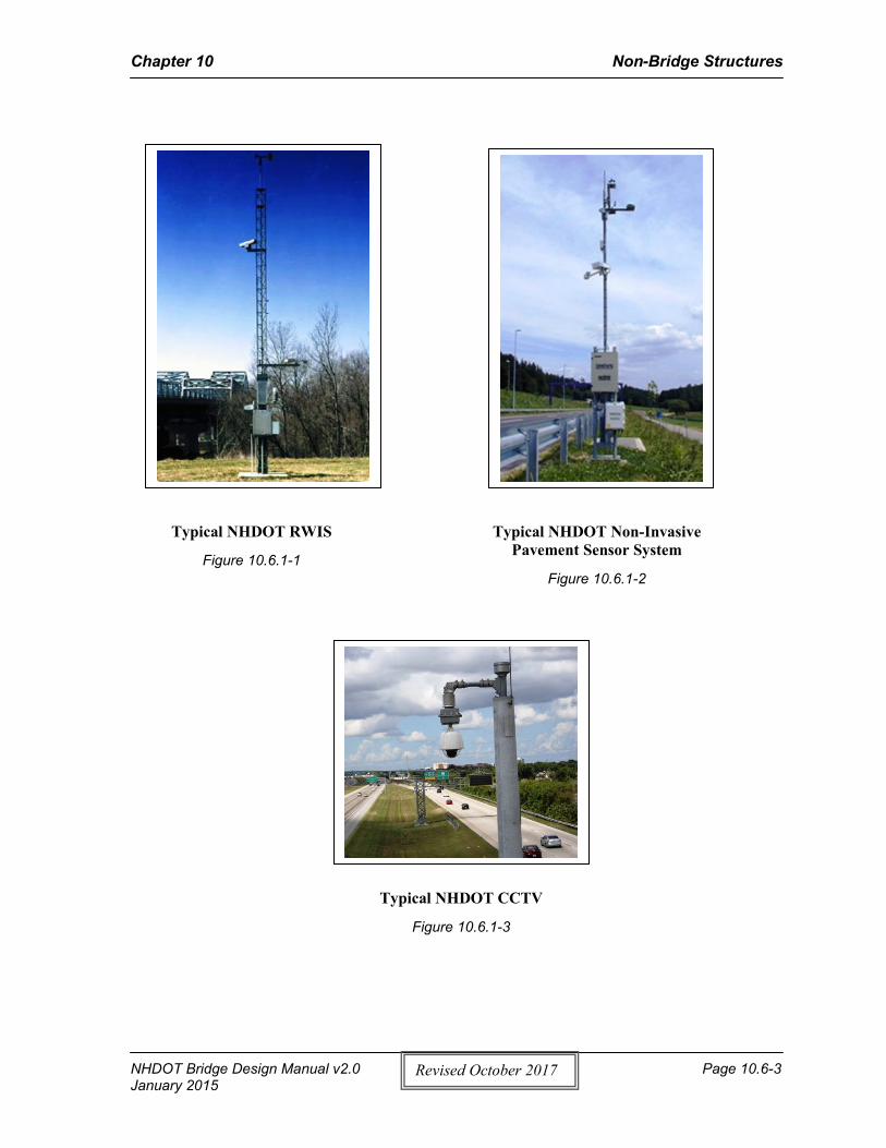
The design of CCTV systems is a combined effort between the Transportation Management Center, the Bureau of Bridge Design, Bureau of Materials and Research, and the supplier of the structure. Bridge Design and Materials and Research are responsible for the preliminary and final design of the CCTV pole foundation for In-House projects. For Consultant projects, Consultants are responsible for the preliminary and final design of the foundation, with the guidance from Materials and Research and Bridge Design. The supplier of the pole is responsible for the design of the pole and submits shop drawings (through the Contractor) to the Department or the Consultant for approval. The supplier’s calculations and shop plans (stamped by a NH PE) are reviewed for general conformance with the Contract Plans and NHDOT policies and specifications. See Figure 10.6.1-3 for a typical CCTV.
B. Road and Weather Information Station (RWIS)
The design of Road and Weather Information Station Systems is a combined effort between the Transportation Management Center, the Bureau of Bridge Design, and the supplier of the structure and foundation. The supplier of the pole is responsible for the design of the pole and foundation and submits shop drawings and calculations to the Department for approval. Bridge Design is responsible for reviewing the pole and foundation shop plans and calculations (stamped by a NH PE) for general conformity, for In-House projects. For Consultant projects, the design Consultant is responsible for reviewing the pole and foundation shop plans and calculations (stamped by a NH PE) for general conformity. See Figure 10.6.1-1 for a typical RWIS.
C. Non-Invasive Pavement Sensor Systems
The design of Non-Invasive Pavement Sensor Systems is a combined effort between the Transportation Management Center, the Bureau of Bridge Design, and the supplier of the structure and foundation. The supplier of the pole is responsible for the design of the pole and foundation and submits shop drawings and calculations to the Department for approval. Bridge Design is responsible for reviewing the pole and foundation shop plans and calculations (stamped by a NH PE) for general conformity, for In-House projects. For Consultant projects, the design Consultant is responsible for reviewing the pole and foundation shop plans and calculations (stamped by a NH PE) for general conformity. See Figure 10.6.1-2 for a typical Non-Invasive Pavement Sensor.
D. Coordination of CCTV Support Pole and Foundation
1) Once the contract is awarded, the Contractor shall submit shop drawings of the CCTV support pole(s), design calculations, and top of foundation reactions for each pole location to
Chapter 10 Non-Bridge Structures
NHDOT Bridge Design Manual v2.0 Page 10.6-2 January 2015
Revised October 2017
the Bureau of Bridge Design for approval in accordance with Section 105.02 of the NHDOT Standard Specifications and the special provision. The Contractor shall also indicate which foundation he will be installing: spread footing or drilled shaft foundation.
⇒ The Bureau of Bridge Design or the design Consultant will use the top of foundation reactions from the fabricator to verify or modify the preliminary foundation design that was included in the contract, for a final design.
⇒ The Bureau of Bridge Design or the design Consultant shall review the Fabricator’s shop plans for conformity with the contract plans, proposal, specifications, and NHDOT policy. The shop plans shall be stamped “Approved”, “Approved Except as Noted” or “Disapproved”, and returned to the Bureau of Construction for distribution to the Contractor and Fabricator.
2) Distribution of Plans: ⇒ Distribute the following to the Bureau of Construction:
Four (4) copies of “Approved” stamped structure shop plans Four (4) copies of the foundation plan stamped “Final Design”.
⇒ Distribute the following to the Fabrication Engineer, Bureau of Bridge Design: One (1) copy of the “Approved” stamped structure shop plans with a
transmittal noting the project name, number, fabricator, location, and noting that the copy is to be distributed to the shop inspector.
⇒ Distribute the following to the Transportation Management Center: One (1) copy of “Approved” stamped structure shop plans One (1) copy of “Approved” stamped foundation shop plans stamped “Final
Design”.
3) Archiving the Plans: ⇒ Archive the foundation support structure plans in the Bureau of Bridge Design:
A folder labeled with the project name and number containing one (1) half-size copy of the “Approved” stamped shop plans, foundation plans, and any correspondence and shall be placed in the project folder (if applicable). A copy should also be filed in the ITS file cabinet located in the Bureau of Bridge Design.
Chapter 10 Non-Bridge Structures
NHDOT Bridge Design Manual v2.0 Page 10.6-3 January 2015
Revised October 2017
Typical NHDOT CCTV
Figure 10.6.1-3
Typical NHDOT Non-Invasive Pavement Sensor System
Figure 10.6.1-2
Typical NHDOT RWIS
Figure 10.6.1-1

Chapter 10 Non-Bridge Structures
NHDOT Bridge Design Manual v2.0 Page 10.6-4 January 2015
Revised October 2017
10.6.2 Dynamic Message Sign (DMS) Overhead Structures
All dynamic message sign (DMS) overhead structures and foundations shall be designed, fabricated, and constructed in accordance with the current edition of AASHTO LRFD Specifications for Structural Supports for Highway Signs, Luminaires, and Traffic Signals, including interims, ASCE/SEI 7 Minimum Design Loads For Buildings and other Structures, NHDOT Bridge Design Manual Chapter 10, and the current NHDOT Special Provisions, Section 677.xx – Permanent Fixed Location Dynamic Message Sign System.
The design of DMS overhead structures is a combined effort between the Transportation Management Center, the Bureau of Bridge Design, and the Manufacturer of the structure. Bridge Design is responsible for the preliminary and final design of the foundations for In-House projects. Consultants are responsible for the preliminary and final design of the foundations, with the guidance of Bridge Design and Materials and Research, for Consultant projects. The Manufacturer of the structure is responsible for the design of the structure and shall submit shop drawings to the Department (through the Contractor) for approval. The Manufacturer’s calculations and shop plans are reviewed for general conformity with Contract Plans and NHDOT policies and specifications.
The design process and coordination shall be as noted in Chapter 10, Section 10.3.5. The Department will furnish the foundation design plans for the DMS overhead structure to the Contractor after approval of the overhead structure shop drawings.
10.6.3 Luminaire Support Structures
A. Light Poles with Mast Arm
The typical light poles with mast arm and foundation (light pole bases) shall be designed, fabricated, and constructed in accordance with the current edition of AASHTO Standard Specifications for Structural Supports for Highway Signs, Luminaires, and Traffic Signals, including interims; the current NHDOT Standard Specifications for Road and Bridge Construction, Section 625, Light Pole Bases; and any special provision.
Typical NHDOT DMS Overhead Structure
Figure 10.6.2-1

Chapter 10 Non-Bridge Structures
NHDOT Bridge Design Manual v2.0 Page 10.6-5 January 2015
Revised October 2017
Standard foundation designs for typical light pole bases are provided in the NHDOT Standard Plans for Road Construction, SL-2, Concrete Foundations and Light Pole Base Type B located at: http://www.nh.gov/dot/org/projectdevelopment/highwaydesign/standardplans/index.htm.
B. High-mast Light Poles
High-mast light poles (towers) shall be designed, fabricated, and constructed in accordance with the current edition of AASHTO Standard Specifications for Structural Supports for Highway Signs, Luminaires, and Traffic Signals, including interims; and the current NHDOT Standard Specifications for Road and Bridge Construction and any special provisions.
Typical NHDOT Light Pole with Mast Arm
Figure 10.6.3-1
Typical NHDOT High-mast Light Poles
Figure 10.6.3-2

Chapter 10 Non-Bridge Structures
NHDOT Bridge Design Manual v2.0 Page 10.6-6 January 2015
Revised October 2017
Page intentionally left blank.

Chapter 10 Non-Bridge Structures
NHDOT Bridge Design Manual v2.0 Page 10.R-1 January 2015
Revised October 2017
References 1. American Association of State Highway and Transportation Officials (AASHTO), AASHTO
LRFD Bridge Design Specifications, 7th Ed., 2014, Washington, D.C.
2. American Association of State Highway and Transportation Officials (AASHTO), Standard Specifications for Highway Bridges, 17th Ed., 2002, Washington, D.C.
3. American Association of State Highway and Transportation Officials (AASHTO), Standard Specifications for Structural Supports for Highway Signs, Luminaires, and Traffic Signals, 6th Ed., 2013, Washington, D.C.
4. American Society of Civil Engineers (ASCE 7-10), Minimum Design Loads for Buildings and Other Structures, 2013, Reston, Virginia.
5. Federal Highway Administration (FHWA), FHWA Guidelines for the Installation, Inspection, Maintenance and Repair of Structural Supports for Highway Signs, Luminaires, and Traffic Signals, Publication No. FHWA NHI05-036, March 2005, Washington, D.C. Retrieved from http://www.fhwa.dot.gov/bridge/signinspection03.cfm#fig34
6. Johannessen & Leone Associates, WIND Speed by Zip Retrieved from http://www.windspeedbyzip.com/
7. New Hampshire Department of Transportation Bureau of Bridge Design, Bridge Design Manual, October1, 2000, Concord, NH
8. New Hampshire Department of Transportation Bureau of Highway Design, Highway Design Manual, 2007, Vol. 1, Concord, NH
9. New Hampshire Department of Transportation, NHDOT Standard Specifications for Road and Bridge Construction 2010, Concord, NH
10. US Army Corps of Engineers, Ground Snow Loads for New Hampshire, February 2002, Cold regions Research and Engineering Laboratory ERDC/CRREL TR-02-6 Retrieved from www.senh.org/wp-content/uploads/2010/12/tr02-6.pdf
11. Weather Underground, Inc., Weather Underground Map Retrieved from http://www.wunderground.com/wundermap/?lat=43.208099&lon=-71.537598&zoom=8&type=lightmap&rad=0&sat=0&stormreports=0&svr=0&pix=0&cams=0&tor=0&riv=0&wxsn=1&wxsn.mode=temp&wxsn.opa=50&wxsn.bcdgtemp=0&wxsn.rf=1&ski=0&tfk=0&mm=0&ndfd=0&fire=0&firewfas=0&extremes=0&hurrevac=0&sst=0&livesurge=0&femaflood=0&tsunami=0&seismicrisk=0&fault=0&fissures=0&fronts=0&dir=1&dir.mode=driving&hur=0

Chapter 10 Non-Bridge Structures
NHDOT Bridge Design Manual v2.0 Page 10.R-2 January 2015
Revised October 2017
Page intentionally left blank.

Appendix 10.2-A1 Special Wind Region Map for NH
NHDOT Bridge Design Manual v2.0 Page 10.2-A1-1 January 2015
Revised October 2017
Special Wind Region Map • For the Special Wind Region (i.e. regions along the NH-VT border and Franconia
Notch) as shown in AASHTO LRFD Figure 3.8-1b and 2b, the maximum-recorded wind speed in this area shall be used if it is greater than basic wind speed. See Chapter 4, Section 4.3.11 Wind Loads, for additional information.
• For wind speeds in the Special Wind Region, weather station data can be accessed by clicking on the markers (weather stations) on the weather underground map located at: http://www.wunderground.com/wundermap/?lat=43.63526535&lon=-72.25418091&zoom=8&pin=Lebanon%2c%20NH
• The basic wind speed for the design of sign structures and CCTV pole supports shall be 130-mph (209-km.hr) as noted in Chapter 10, Section 10.2.
• The basic wind speed for the design of bridges, RWIS, and non-invasive pavement sensor supports shall be 120-mph (193-km.hr) as noted in Chapter 10, Section 10.2.

Appendix 10.2-A1 Special Wind Region Map for NH
NHDOT Bridge Design Manual v2.0 Page 10.2-A1-2 January 2015
Revised October 2017
Special Wind Region for NH
8'-
6"
4'-
3"
7'-0"
4'-
4"
2'-
0"
3"
9
#4
A4
SP
@
8" 2'-0"
**
*
* *
*
À MAST ARM
À COLUMN
* ITEM NUMBERS ARE FOR SPECIFICATION REFERENCE ONLY.
NO SEPARATE PAYMENT WILL BE MADE FOR THESE ITEMS.
MARK SIZE NO.
A1
A2
A3
#4
(2'-6"Âx4'-4")
TYPE 1A
(3'-0"Âx4'-10")
TYPE 1B
(3'-0"Âx4'-10")
TYPE 1C
-
CONDUIT (IF REQUIRED)
3" Â STREET LIGHT
1" CHAMFER
JOINT
CONSTRUCTION
(8'x7'x2')
TYPE 1B
NUMBER
ITEMITEM QUANTITY
TYPICAL QUANTITIES PER BASE
206.1* COMMON STRUCTURE EXCAVATION
REINFORCING STEEL544*
(PLACE AS REQUIRED)
3" Â SIGNAL CONDUIT
LENGTH
UNBENTTYPE
TYPE 1A REINFORCING SCHEDULE
A4 9
14
#4
#4
JOINT
CONSTRUCTION
TRAFFIC SIGNAL MAST ARM FOUNDATION - TYPE 1A
PLAN VIEW
SECTION A-A
A
6" 6"
7 #4A1 SPACED EVENLY (BOT)
7 #4A1 SPACED EVENLY (TOP) 6" 6"
9 #4A2 SPACED EVENLY (BOT)
9 #4A2 SPACED EVENLY (TOP)
18
8'-0"
6'-6"
END ELEVATION VIEWELEVATION VIEW
IN SECT. A-A)
(PLACE AS SHOWN
#7A3 Ó
#7 12
#7A3 Ó
#4A2 #4A1
5'-
5"
1'-0"
5"
R3"
6'-10"
135° BENDS
STANDARD #4A4
3"
#4A4
#4A4
1"
SPACED EVENLY
12 #7A3 Ó
1" PROJECTION
3" Â CONDUIT3'-0" SUBSID.
CONDUIT TO
AS REQUIRED
ANCHOR RODS
A
FOUNDATION
CONCRETE
(VERTICAL)
À ANCHOR ROD
PLATE
BASE
SCREEN DETAIL
520.21* CONCRETE CLASS B, FOOTINGS
(8'-6"x7'x2')
TYPE 1A
(9'x7'x2')
TYPE 1C
(3'-0"Âx4'-10")
TYPE 1D
(9'x8'-6"x2')
TYPE 1D
(9'x9'x2')
TYPE 1E
7'-7"
5.2 CY
(3'-0"Âx5'-4")
TYPE 1E
MANUFACTURER'S RECOMMENDATION
SET ACCORDING TO
ANCHOR RODS SHALL BE
MAX h = 40'-0"
MAX h1 = 20'-0" MAX h1 = 20'-0"
MAX L = 25'-0"MAX L = 25'-0"
MAX L = 40'-0"
WITH LUMINAIRE
CASE 1
WITHOUT LUMINAIRE
CASE 2
MAX L = 45'-0" MAX L = 45'-0"
MAX L = 55'-0" MAX L = 55'-0"
MAX L = 60'-0" MAX L = 60'-0"
366 LB
21 CY
2'-3" 2'-6" 2'-3"
GENERAL NOTES (TYPE 1 FOUNDATION)
209.1* 16.1 CY
GRANULAR BACKFILL
h
h1
L
h1
L
GRANULAR BACKFILL
REQUIRED FOUNDATION DIMENSIONS
LENGTH
AND
DIAMETER
STEM
DIMENSIONS
FOOTING
(SEE NOTE NO. 6)
STAINLESS STEEL WIRE CLOTH
STATE PROJECT NO. SHEET NO. TOTAL SHEETS
SH
EE
T
CH
EC
KE
D
AS
BUI
LT
DE
TAI
LS
DA
TE
DA
TE
DA
TE
DA
TE
NU
MB
ER
DA
TE
ST
ATI
ON
ST
ATI
ON
DE
SC
RI
PTI
ON
RE
VI
SI
ON
S
AF
TE
R
PR
OP
OS
AL
XX
DGN
2016_ma_fd_1a_rev
STATE OF NEW HAMPSHIRE
SD
R
PR
OC
ES
SE
D
NE
W
DE
SI
GN
BUREAU OF TRAFFICDEPARTMENT OF TRANSPORTATION
X XX
Foundation - Type 1A
Traffic Signal Mast Arm
KF
D
NA
ME3
01/15/2016
DA
TE3
1. THERE SHALL BE A MINIMUM OF ONE TEST BORING REQUIRED, AT THE APPROXIMATE FOUNDATION
LOCATION, TO CONFIRM THE ENGINEERING PROPERTIES OF THE SOILS PROVIDING FOUNDATION
SUPPORT. THE ENGINEER MAY REQUIRE ADDITIONAL BORINGS IF CONSIDERED NECESSARY.
2. ALL REINFORCING STEEL SHALL CONFORM TO AASHTO M31/M31M, GRADE 60 (420). ALL
REINFORCING STEEL SHALL BE A MINIMUM OF 3 INCHES FROM CONCRETE SURFACES, UNLESS
NOTED OTHERWISE, AND SHALL MEET THE REQUIREMENTS OF SECTION 544.
3. CONCRETE SHALL BE CLASS B HAVING A MINIMUM 28 DAY COMPRESSIVE STRENGTH OF 3000
PSI PLACED IN CONFORMANCE WITH SECTION 520. CYLINDERS FOR STRENGTH TESTING SHALL
BE TAKEN DURING CONCRETE PLACEMENT.
4. BEARING CAPACITY IS BASED ON THE ALLOWABLE STRESS DESIGN. THE ALLOWABLE BEARING
CAPACITY SHALL BE A MINIMUM OF 1• TONS/SF AFTER THE APPLICATION OF A FACTOR
OF SAFETY OF 3 TO THE ULTIMATE BEARING CAPACITY.
5. FOOTING CONCRETE SHALL BE PLACED ON UNDISTURBED MATERIAL. UNSUITABLE MATERIAL
FOUND AT THE BOTTOM OF FOOTING GRADE SHALL BE REMOVED AND REPLACED WITH
STRUCTURAL FILL, ITEM 508, AS DIRECTED BY THE ENGINEER. STRUCTURAL FILL USED
IN EXCESS OF THE AMOUNT SPECIFIED ON THE PROJECT PLANS OR UNDER ITEM 616.1XX
WILL BE PAID AS EXTRA WORK IN ACCORDANCE WITH 109.04.
6. STAINLESS STEEL STD. GR. WIRE CLOTH. ‚" MAX. OPENING WITH MIN. WIRE DIA. OF
AWG NO. 16 WITH 2" LAP. SECURE WITH ƒ" STAINLESS STEEL BANDING AFTER ANCHOR
RODS ARE FULLY TIGHTENED.
7. NO GROUT SHALL BE PLACED BETWEEN THE FOUNDATION AND BOTTOM OF THE BASE PLATE.
8. THE EXPOSED LENGTH OF THE ANCHOR ROD BETWEEN THE TOP OF THE FOUNDATION AND THE
BOTTOM OF THE LEVELING NUT SHOULD NOT EXCEED ONE ROD DIAMETER (MAXIMUM) OR
1-INCH (PREFERRED).
9. FOR THE INSTALLATION, PRETENSIONING AND ULTRASONIC TESTING OF ANCHOR RODS, SEE
THE SPECIAL PROVISION AMENDMENT TO SECTION 616, TRAFFIC SIGNALS.
11. EXCAVATION AND BACKFILL QUANTITIES ARE BASED ON AN EXCAVATED AREA ONE FOOT CLEAR
OF THE FOUNDATION SIDES AND TO THE BOTTOM OF THE FOOTING.
12. WHERE BEDROCK IS ENCOUNTERED, EXCAVATION SHALL STILL EXTEND TO LIMITS SHOWN.
13. TYPE 1 FOUNDATIONS SHALL BE PAID FOR UNDER ITEM 616.1XX.
14. SEE THE TYPE 1B & TYPE 1C FOOTING SPECIAL DETAIL.
15. SEE THE TYPE 1D & TYPE 1E FOOTING SPECIAL DETAIL.
DESIGN OR THE BUREAU OF TRAFFIC.
WITHOUT DESIGN APPROVAL FROM EITHER THE BUREAU OF BRIDGE
THOSE SHOWN ON THE SPECIAL DETAIL SHALL NOT BE USED
ATTACHMENT LAYOUTS. ATTACHMENT COMBINATIONS OTHER THAN
NOTE: SEE TRAFFIC SIGNAL MAST ARM LAYOUT SPECIAL DETAIL FOR
REVISION DATE
10-09-17
BENT (HOOKED OR J-BOLT) ANCHOR RODS SHALL NOT BE USED.
END OF THE ANCHOR ROD SHALL HAVE EITHER ONE NUT TACKED WELDED OR DOUBLE NUTS.
FLAT HARDENED WASHERS (ASTM F436). LOCK WASHERS SHALL NOT BE USED. THE EMBEDDED
WITH A MINIMUM OF THREE HEX NUTS (ASTM A563 OR ASTM A194) AND A MINIMUM OF TWO
GALVANIZE THE ENITRE ROD PER ASTM A153. EACH ANCHOR ROD SHALL BE SUPPLIED
10. ANCHOR RODS SHALL BE STRAIGHT RODS AND CONFORM TO ASTM F1554 GRADE 50 (MIN.).

2'-6"2'-6"
4'-
0"
8'-
0"
7'-0"
4'-
10"
2'-
0"
8
#5
B4
SP
@
10"
4'-
6"
9'-
0"
7'-0"
4'-
10"
2'-
0"
8
#5
C6
SP
@
10"
CONDUIT (IF REQUIRED)
3" Â STREET LIGHT
(PLACE AS REQUIRED)
3" Â SIGNAL CONDUIT
MARK SIZE NO.
B1
B2
B3
#4
LENGTH
UNBENTTYPE
TYPE 1B REINFORCING SCHEDULE
8
16
16
14
#4
#7
#5B4
TRAFFIC SIGNAL MAST ARM FOUNDATION - TYPE 1B
SECTION B-B
7'-6"
6'-6"
1'-0"
5"
R3"
5'-
11"
7'-4"
135° BENDS
STANDARD #5B4
4"
#5B4
SPACED EVENLY
16 #7B3 Ó
3'-0" SUBSID.
CONDUIT TO
* ITEM NUMBERS ARE FOR SPECIFICATION REFERENCE ONLY.
NO SEPARATE PAYMENT WILL BE MADE FOR THESE ITEMS.
NUMBER
ITEMITEM QUANTITY
TYPICAL QUANTITIES PER BASE
206.1* COMMON STRUCTURE EXCAVATION
REINFORCING STEEL544*
520.21* CONCRETE CLASS B, FOOTINGS
FOUNDATION
CONCRETE
(VERTICAL)
À ANCHOR ROD
PLATE
BASE
SCREEN DETAIL
NOTES
9'-3"
5.4 CY
22 CY
457 LB
209.1* 16.6 CYGRANULAR BACKFILL
(SEE NOTE NO. 6 ON TS-1)
STAINLESS STEEL WIRE CLOTH
CONDUIT (IF REQUIRED)
3" Â STREET LIGHT
(PLACE AS REQUIRED)
3" Â SIGNAL CONDUIT
MARK SIZE NO.
C1
C2
C3
#4
LENGTH
UNBENTTYPE
TYPE 1C REINFORCING SCHEDULE
8
9
7#5
#4
#5C6
TRAFFIC SIGNAL MAST ARM FOUNDATION - TYPE 1C
SECTION C-C
C4 #5 9
8'-6"
6'-6"
6'-6"
8'-6"
C5 #7 16
1'-0"
5"
R3"
5'-
11"
7'-4"
135° BENDS
STANDARD #5C6
4"
#5C6
SPACED EVENLY
16 #7C5 Ó
3'-0" SUBSID.
CONDUIT TO
* ITEM NUMBERS ARE FOR SPECIFICATION REFERENCE ONLY.
NO SEPARATE PAYMENT WILL BE MADE FOR THESE ITEMS.
ITEM QUANTITY
206.1* COMMON STRUCTURE EXCAVATION
CONCRETE CLASS B, FOOTINGS
9'-3"
5.9 CY
24 CY
519 LB
520.21*
544* REINFORCING STEEL
NUMBER
ITEM
TYPICAL QUANTITIES PER BASE
209.1* 18.3 CY
7
GRANULAR BACKFILL
À MAST ARM
À COLUMN
PLAN VIEW
1" CHAMFER
JOINT
CONSTRUCTION
JOINT
CONSTRUCTION
3"
6" 6"
6" 6"
8 #4B2 SPACED EVENLY (BOT)
8 #4B2 SPACED EVENLY (TOP)
7 #4B1 SPACED EVENLY (BOT)
7 #4B1 SPACED EVENLY (TOP)
END ELEVATION VIEW
ELEVATION VIEW
IN SECT. B-B)
(PLACE AS SHOWN
#7B3 Ó
#7B3 Ó
#4B2
#4B1
#5B4
B B
1" PROJECTION
3" Â CONDUIT
AS REQUIRED
ANCHOR RODS
5"
MANUFACTURER'S RECOMMENDATION
SET ACCORDING TO
ANCHOR RODS SHALL BE
2'-0" 3'-0" 2'-0"
GRANULAR BACKFILL
JOINT
CONSTRUCTION
JOINT
CONSTRUCTION
3"
1" CHAMFER
PLAN VIEW
À MAST ARM
À COLUMN
6" 6"
6" 6"
7 #5C2 SPACED EVENLY (BOT)
7 #4C1 SPACED EVENLY (TOP)
9 #5C4 SPACED EVENLY (BOT)
9 #4C3 SPACED EVENLY (TOP)
END ELEVATION VIEW
ELEVATION VIEW
IN SECT. C-C)
(PLACE AS SHOWN
#7C5 Ó
#7C5 Ó
#4C3
#5C4
#4C1
#5C2
#5C6
C C
1" PROJECTION
3" Â CONDUITAS REQUIRED
ANCHOR RODS
(VERTICAL)
À ANCHOR ROD
PLATE
BASE
FOUNDATION
CONCRETE
SCREEN DETAIL
5"
MANUFACTURER'S RECOMMENDATION
SET ACCORDING TO
ANCHOR RODS SHALL BE
2'-0" 3'-0" 2'-0"
GRANULAR BACKFILL
(SEE NOTE NO. 6 ON TS-1)
STAINLESS STEEL WIRE CLOTH
STATE PROJECT NO. SHEET NO. TOTAL SHEETS
SH
EE
T
CH
EC
KE
D
AS
BUI
LT
DE
TAI
LS
DA
TE
DA
TE
DA
TE
DA
TE
NU
MB
ER
DA
TE
ST
ATI
ON
ST
ATI
ON
DE
SC
RI
PTI
ON
RE
VI
SI
ON
S
AF
TE
R
PR
OP
OS
AL
XX
DGN
2016_ma_fd_1b&c_rev
STATE OF NEW HAMPSHIRE
SD
R
PR
OC
ES
SE
D
NE
W
DE
SI
GN
BUREAU OF TRAFFICDEPARTMENT OF TRANSPORTATION
X XXXX
Foundations - Type 1B & 1C
Traffic Signal Mast Arm
KF
D
NA
ME3
01/15/2016
DA
TE3
NOTES
FOR TYPE 1 FOUNDATION NOTES.
1. SEE MAST ARM FOUNDATION - TYPE 1A SPECIAL DETAIL, FOR TYPE 1 FOUNDATION NOTES.
1. SEE MAST ARM FOUNDATION - TYPE 1A SPECIAL DETAIL,
REVISION DATE
10-09-17

2'-6"
2'-6"
4'-
10"
2'-
0"
4'-
6"
9'-
0"
8'-6"
12
#5
D6
SP
@
6"
2'-
0"
5'-
4"
4'-
6"
9'-
0"
9'-0"
13
#5
E4
SP
@
6
CONDUIT (IF REQUIRED)
3" Â STREET LIGHT
(PLACE AS REQUIRED)
3" Â SIGNAL CONDUIT
MARK SIZE NO.
D1
D2
D3
#4
LENGTH
UNBENTTYPE
TYPE 1D REINFORCING SCHEDULE
12
9
9
9
#5
#4
#5D6
TRAFFIC SIGNAL MAST ARM FOUNDATION - TYPE 1D
SECTION D-D
D4 #5 9
8'-6"
8'-6"
8'-0"
8'-0"
D5 #7 16
1'-0"
5"
R3"
5'-
11"
7'-4"
135° BENDS
STANDARD #5D6
4"
#5D6
SPACED EVENLY
16 #7D5 Ó
3'-0" SUBSID.
CONDUIT TO
* ITEM NUMBERS ARE FOR SPECIFICATION REFERENCE ONLY.
NO SEPARATE PAYMENT WILL BE MADE FOR THESE ITEMS.
NUMBER
ITEMITEM QUANTITY
TYPICAL QUANTITIES PER BASE
206.1* COMMON STRUCTURE EXCAVATION
REINFORCING STEEL544*
520.21* CONCRETE CLASS B, FOOTINGS
FOUNDATION
CONCRETE
(VERTICAL)
À ANCHOR ROD
PLATE
BASE
SCREEN DETAIL
NOTES
6.9 CY
9'-3"
28 CY
610 LB
209.1* 21.3 CYGRANULAR BACKFILL
(SEE NOTE NO. 6 ON TS-1)
STAINLESS STEEL WIRE CLOTH
CONDUIT (IF REQUIRED)
3" Â STREET LIGHT
(PLACE AS REQUIRED)
3" Â SIGNAL CONDUIT
MARK SIZE NO.
E1
E2
E3
#4
LENGTH
UNBENTTYPE
TYPE 1E REINFORCING SCHEDULE
18
18
#6
E4
TRAFFIC SIGNAL MAST ARM FOUNDATION - TYPE 1E
SECTION E-E
#5 13
8'-6"
8'-6"
#7 16
1'-0"
5"
R3"
6'-
5"
7'-10"
135° BENDS
STANDARD #5E4
4"
#5E4
SPACED EVENLY
16 #7E3 Ó
3'-0" SUBSID.
CONDUIT TO
* ITEM NUMBERS ARE FOR SPECIFICATION REFERENCE ONLY.
NO SEPARATE PAYMENT WILL BE MADE FOR THESE ITEMS.
NUMBER
ITEMITEM QUANTITY
TYPICAL QUANTITIES PER BASE
206.1* COMMON STRUCTURE EXCAVATION
REINFORCING STEEL544*
520.21* CONCRETE CLASS B, FOOTINGS 7.4 CY
9'-3"
32 CY
714 LB
209.1* 24.4 CYGRANULAR BACKFILL
JOINT
CONSTRUCTION
JOINT
CONSTRUCTION
3"
1" CHAMFER
PLAN VIEW
À MAST ARM
À COLUMN
6" 6"
6" 6"
9 #5D2 SPACED EVENLY (BOT)
9 #4D1 SPACED EVENLY (TOP)
9 #5D4 SPACED EVENLY (BOT)
9 #4D3 SPACED EVENLY (TOP)
END ELEVATION VIEW
ELEVATION VIEW
IN SECT. D-D)
(PLACE AS SHOWN
#7D5 Ó
#7D5 Ó
#4D3
#5D4
#4D1
#5D2
1"
#5D6
D D
1" PROJECTION
3" Â CONDUITAS REQUIRED
ANCHOR RODS
MANUFACTURER'S RECOMMENDATION
SET ACCORDING TO
ANCHOR RODS SHALL BE
2'-9" 3'-0" 2'-9"
GRANULAR BACKFILL
JOINT
CONSTRUCTION
JOINT
CONSTRUCTION
3"
1" CHAMFER
PLAN VIEW
À MAST ARM
À COLUMN
6" 6"
6" 6"
9 #6E2 SPACED EVENLY (BOT)
9 #4E1 SPACED EVENLY (TOP)
9 #6E2 SPACED EVENLY (BOT)
9 #4E1 SPACED EVENLY (TOP)
END ELEVATION VIEW
ELEVATION VIEW
IN SECT. E-E)
(PLACE AS SHOWN
#7E3 Ó
#7E3 Ó
#4E1
#6E2
#4E1
#6E2
#5E4
1"
E E
1" PROJECTION
3" Â CONDUITAS REQUIRED
ANCHOR RODS
(VERTICAL)
À ANCHOR ROD
PLATE
BASE
FOUNDATION
CONCRETE
SCREEN DETAIL
MANUFACTURER'S RECOMMENDATION
SET ACCORDING TO
ANCHOR RODS SHALL BE
3'-0" 3'-0" 3'-0"
GRANULAR BACKFILL
(SEE NOTE NO. 6 ON TS-1)
STAINLESS STEEL WIRE CLOTH
STATE PROJECT NO. SHEET NO. TOTAL SHEETS
SH
EE
T
CH
EC
KE
D
AS
BUI
LT
DE
TAI
LS
DA
TE
DA
TE
DA
TE
DA
TE
NU
MB
ER
DA
TE
ST
ATI
ON
ST
ATI
ON
DE
SC
RI
PTI
ON
RE
VI
SI
ON
S
AF
TE
R
PR
OP
OS
AL
XX
DGN
2016_ma_fd_1d&e_rev
STATE OF NEW HAMPSHIRE
SD
R
PR
OC
ES
SE
D
NE
W
DE
SI
GN
BUREAU OF TRAFFICDEPARTMENT OF TRANSPORTATION
X XX
Foundations - Type 1D & 1E
Traffic Signal Mast Arm
KF
D
NA
ME3
01/15/2016
DA
TE3
NOTES
FOR TYPE 1 FOUNDATION NOTES.
1. SEE MAST ARM FOUNDATION - TYPE 1A SPECIAL DETAIL,
FOR TYPE 1 FOUNDATION NOTES.
1. SEE MAST ARM FOUNDATION - TYPE 1A SPECIAL DETAIL,
REVISION DATE
10-09-17

2'-6"
3" * *
*
* *
*
-
GENERAL NOTES (TYPE 2 FOUNDATION)
DRILLED HOLES
EXCAVATED HOLES
TRAFFIC SIGNAL MAST ARM FOUNDATION - TYPE 2
* ITEM NUMBERS ARE FOR SPECIFICATION REFERENCE ONLY.
NUMBER
ITEMITEM
REINFORCING STEEL544*
508* STRUCTURAL FILL
F F
MARK
F1
F2
LENGTH
UNBENTTYPE
135° BENDS
STANDARD
ELEVATION VIEW
SECTION F-F
#58'-0"
9'-0"
10'-0"
11'-0"
12'-0"
#7 7'-6"
8'-6"
9'-6"
10'-6"
11'-6"
F2
F1
F2
F1
F2
F1
F2
F1
BAR #
#7
#7
#7
#7
#5
#5
#5
#5
BARS
# OF
"4"
8'-0" 9'-0" 10'-0" 11'-0" 12'-0"
16
16
16
16
16
#5F2
15 @ 8"
22 @ 6"
24 @ 6"
9'-3"
9'-3"
9'-3"
9'-3"
9'-3"
11 @ 10"
10 @ 10"
2.1 2.4 2.6 2.9
UNIT
CY
CY
LB
REINFORCING SCHEDULE
(PLACE AS REQUIRED)
3" Â SIGNAL CONDUIT
CONDUIT (IF REQUIRED)
3" Â STREET LIGHT
(T
YP)
3"
CL
EA
R
IN SECT. F-F)
(PLACE AS SHOWN
#7F1
SPACED EVENLY
16 #7F1
#5F2
3'-0" SUBSID.
CONDUIT TO
1" PROJECTION
3" Â CONDUIT
NO SEPARATE PAYMENT WILL BE MADE FOR THESE ITEMS.
FOUNDATION
CONCRETE
(VERTICAL)
À ANCHOR ROD
PLATE
BASE
SCREEN DETAIL
1" CHAMFER
(SEE GENERAL NOTE NO. 8)
STAINLESS STEEL WIRE CLOTH
MANUFACTURER'S RECOMMENDATION
SET ACCORDING TO
ANCHOR RODS SHALL BE
MAX h = 40'-0"
MAX h1 = 20'-0" MAX h1 = 20'-0"
WITHOUT LUMINAIRE
CASE 2
WITH LUMINAIRE
CASE 1
MAX L = 20'-0"
MAX L = 20'-0" MAX L = 25'-0"
MAX L = 35'-0" MAX L = 40'-0"
MAX L = 50'-0" MAX L = 55'-0"
MAX L = 60'-0" MAX L = 60'-0"
20
342
22
384 455
26
556
28
608
508. NO PAYMENT SHALL BE MADE FOR STRUCTURAL FILL OR EXCAVATION.
4. THE EXCAVATED HOLE SHALL BE BACKFILLED TO THE LIMITS OF EXCAVATION WITH STRUCTURAL FILL ACCORDING TO SECTION
THIS IS NOT POSSIBLE THEN THE ENGINEER SHALL REQUEST A REDESIGN.
3. ANY BEDROCK ENCOUNTERED SHALL BE REMOVED TO THE SAME LIMITS AS DESCRIBED FOR SOIL (SEE PREVIOUS NOTE). IF
2. THE EXCAVATED HOLE SHALL BE AT LEAST 3 FT CLEAR OF THE FOUNDATION SIDES AND 1 FT DEEPER THAN THE FOUNDATION.
ALTERNATIVELY A PRECAST CIRCULAR SHAFT FOUNDATION SHALL BE INSTALLED.
EXCAVATED HOLE. THE FOUNDATION SHALL BE CAST IN PLACE USING FORMS (WHICH MUST BE REMOVED) OR
1. AS AN ALTERNATIVE TO A DRILLED HOLE, THE CIRCULAR SHAFT FOUNDATION CONCRETE SHALL BE CONSTRUCTED IN AN
DENOTES EXCAVATED HOLE METHOD OF CONSTRUCTION FOR CIRCULAR SHAFTS
(SEE GENERAL NOTE 3)
FINISHED GRADE
CONCRETE CLASS AAA
OR
CONCRETE CLASS A
520.001*
OR
520.1*
24
3.1
h
h1
L
h1
L
SHAFT DIAMETER
3'-0"
(S
EE
RE
QUI
RE
D
SH
AF
T
DI
ME
NSI
ON
S
TA
BL
E)
SH
AF
T
LE
NG
TH
(S
EE
REI
NF
OR
CI
NG
SC
HE
DU
LE
TA
BL
E
FO
R
SP
ACI
NG)
#5
F2
REQUIRED SHAFT DIMENSIONS
LENGTH
AND
DIAMETER
SHAFT
3'-0"x9'-0"
3'-0"x8'-0"
3'-0"x10'-0"
3'-0"x11'-0"
3'-0"x12'-0"
LENGTH
SHAFT
QUANTITY PER SHAFT LENGTH (MIN)
TYPICAL QUANTITIES FOR SHAFT LENGTH
13. TYPE 2 FOUNDATIONS SHALL BE PAID FOR UNDER ITEM 616.1XX.
544.
MINIMUM OF 3 INCHES FROM CONCRETE SURFACES, UNLESS NOTED OTHERWISE, AND MEET THE REQUIREMENTS OF SECTION
12. ALL REINFORCING STEEL SHALL CONFORM TO AASHTO M31/M31M, GRADE 60 (420). ALL REINFORCING STEEL SHALL BE A
AMENDMENT TO SECTION 616, TRAFFIC SIGNALS.
11. FOR THE INSTALLATION, PRETENSIONING AND ULTRASONIC TESTING OF ANCHOR RODS, SEE THE SPECIAL PROVISION
SHOULD NOT EXCEED ONE ROD DIAMETER (MAXIMUM) OR 1-INCH (PREFERRED).
10. THE EXPOSED LENGTH OF THE ANCHOR ROD BETWEEN THE TOP OF THE FOUNDATION AND THE BOTTOM OF THE LEVELING NUT
9. NO GROUT SHALL BE PLACED BETWEEN THE FOUNDATION AND BOTTOM OF THE BASE PLATE.
SECURE WITH ƒ" STAINLESS STEEL BANDING AFTER ANCHOR RODS ARE FULLY TIGHTENED.
8. STAINLESS STEEL STD. GR. WIRE CLOTH. ‚" MAX. OPENING WITH MIN. WIRE DIA. OF AWG NO. 16 WITH 2" LAP.
TO ARRANGE FOR PLANT INSPECTION AT LEAST 14 DAYS PRIOR TO CASTING.
DURING THE PRECASTING AT THE PLANT IS REQUIRED. CONTACT THE BUREAU OF MATERIALS AND RESEARCH AT 271-1656
STRENGTH OF 5000 PSI CONSTRUCTED IN CONFORMANCE WITH SECTION 520. INSPECTION BY A DEPARTMENT REPRESENTATIVE
7. CONCRETE FOR A PRECAST CIRCULAR SHAFT FOUNDATION SHALL BE CLASS AAA WITH A MINIMUM 28 DAY COMPRESSIVE
PLACEMENT.
PLACED IN CONFORMANCE WITH SECTION 520. CYLINDERS FOR STRENGTH TESTING SHALL BE TAKEN DURING CONCRETE
6. CAST IN PLACE CONCRETE SHALL BE CLASS A HAVING A MINIMUM 28 DAY COMPRESSIVE STRENGTH OF 3000 PSI AND BE
METHOD ONLY, AS DESCRIBED IN THE DRILLED HOLE NOTES.
5. WHERE BEDROCK IS ENCOUNTERED, A REDUCTION IN CIRCULAR SHAFT LENGTH MAY BE POSSIBLE FOR THE DRILLED HOLE
THE RESULTING TRENCHES SHALL BE BACKFILLED WITH STRUCTURAL FILL CONFORMING TO SECTION 508.
POSSIBLE IN PLACING OF THE CONDUITS (APPROXIMATELY 2.5 FT MAXIMUM DOWN FROM THE EXISTING GROUND SURFACE).
4. TRENCHES FOR THE CONDUITS SHALL BE HAND DUG NEAR THE PROPOSED FOUNDATION, DISTURBING AS LITTLE SOIL AS
CONDITIONS WITH THE GEOTECHNICAL SECTION AND EVALUATE WHETHER A REDESIGN IS REQUIRED.
OR GREATER LATERAL CAPACITY, AS COMPARED TO THIS SOIL MODEL, THEN THE ENGINEER WILL REVIEW THE FOUNDATION
AND NEAR SURFACE GROUNDWATER TABLE. IF THE SOIL PROVIDING FOUNDATION SUPPORT CANNOT GENERATE AN EQUIVALENT
(COHESIONLESS) SOILS HAVING A FRICTION ANGLE OF 32 DEGRESS, MAXIMUM GROUND SURFACE STEEPNESS OF 4H:1V,
3. THE EVALUATION OF GEOTECHNICAL LATERAL CAPACITY IS BASED ON A SOIL MODEL COMPRISED OF HOMOGENEOUS GRANULAR
EXCAVATION METHOD. PRECAST CONCRETE SHALL ONLY BE USED WITH THE EXCAVATED HOLE METHOD.
THE NOTES PROVIDED BELOW FOR EACH METHOD. CAST IN PLACE CONCRETE SHALL BE AN OPTION FOR EITHER
2. THE CIRCULAR SHAFT FOUNDATION SHALL BE CONSTRUCTED IN EITHER A DRILLED HOLE OR IN AN EXCAVATED HOLE PER
BORINGS IF CONSIDERED NECESSARY.
THE ENGINEERING PROPERTIES OF THE SOILS PROVIDING FOUNDATION SUPPORT. THE ENGINEER MAY REQUIRE ADDITIONAL
1. THERE SHALL BE A MINIMUM OF ONE TEST BORING REQUIRED, AT THE APPROXIMATE FOUNDATION LOCATION, TO CONFIRM
BE COMPLETED AS APPROVED BY THE ENGINEER.
6. IF THE DRILLED HOLE METHOD IS PERFORMED AND THE SOILS ARE FOUND TO BE UNSUITABLE, AN EXCAVATED HOLE SHALL
TO CONSTRUCTING THE SHAFT. PLACEMENT AND COMPACTION OF THE FILL SHALL BE IN ACCORDANCE WITH SECTION 203.
5. WHERE FILL EMBANKMENT IS TO BE CONSTRUCTED ABOVE THE EXISTING GROUND, THE EMBANKMENT SHALL BE BUILT PRIOR
BEYOND THE SPECIFIED SOIL-BASED LENGTH GIVEN ON THE PLANS.
A MINIMUM SHAFT LENGTH OF 5 FEET SHALL BE OBTAINED. IT IS NOT NECESSARY TO EXTEND THE SHAFT IN BEDROCK
4. WHERE BEDROCK IS ENCOUNTERED, THE DRILL SHALL PENETRATE THE BEDROCK A MINIMUM OF 3 FEET AND IN ALL CASES
A DRILLED HOLE SHALL BE AT A STABILIZED, STATIC LEVEL AT THE TIME OF CONCRETE PLACEMENT.
THE STANDARDS FOR A DRY EXCAVATION AND FREE FALL PLACEMENT METHOD CANNOT BE MET. THE WATER LEVEL WITHIN
3. UNDERWATER PLACEMENT PROCEDURES (TREMIE OR PUMPING METHODS) SHALL BE REQUIRED WITHIN A DRILLED HOLE WHERE
WITH THE TOP HAVING A SMOOTH LEVEL FINISH.
2. THE EXPOSED PORTION OF THE SHAFT AND TO A DEPTH OF AT LEAST 12 INCHES SHALL HAVE A FORMED APPEARANCE
EXCAVATION, THE ARRANGEMENT OF THE REINFORCING BARS, AND THE ANCHOR BOLTS PRIOR TO CONCRETE PLACEMENT.
FREEFALL OR UNDERWATER. THE CONTRACTOR SHALL COORDINATE WITH THE ENGINEER FOR VISUAL INSPECTION OF THE
CAGE TO THE EXCAVATION SIDES WITH MINIMAL USE OF VIBRATION EQUIPMENT WHETHER THE METHOD OF PLACEMENT IS
USING TEMPORARY CASING IF NECESSARY. THE CONCRETE MIX SHALL BE CAPABLE OF FLOWING THROUGH THE REINFORCING
1. THE CIRCULAR SHAFT FOUNDATION SHALL BE CONSTRUCTED OF CAST IN PLACE CONCRETE AGAINST UNDISTURBED MATERIAL
STATE PROJECT NO. SHEET NO. TOTAL SHEETS
SH
EE
T
CH
EC
KE
D
AS
BUI
LT
DE
TAI
LS
DA
TE
DA
TE
DA
TE
DA
TE
NU
MB
ER
DA
TE
ST
ATI
ON
ST
ATI
ON
DE
SC
RI
PTI
ON
RE
VI
SI
ON
S
AF
TE
R
PR
OP
OS
AL
XX
DGN
2016_ma_fd_2_rev
STATE OF NEW HAMPSHIRE
SD
R
PR
OC
ES
SE
D
NE
W
DE
SI
GN
BUREAU OF TRAFFICDEPARTMENT OF TRANSPORTATION
X XX
Foundation - Type 2
Traffic Signal Mast Arm
KF
D
NA
ME3
01/15/2016
DA
TE3
DESIGN OR THE BUREAU OF TRAFFIC.
WITHOUT DESIGN APPROVAL FROM EITHER THE BUREAU OF BRIDGE
THOSE SHOWN ON THE SPECIAL DETAIL SHALL NOT BE USED
ATTACHMENT LAYOUTS. ATTACHMENT COMBINATIONS OTHER THAN
NOTE: SEE TRAFFIC SIGNAL MAST ARM LAYOUT SPECIAL DETAIL FOR
REVISION DATE
10-09-17
BENT (HOOKED OR J-BOLT) ANCHOR RODS SHALL NOT BE USED.
END OF THE ANCHOR ROD SHALL HAVE EITHER ONE NUT TACKED WELDED OR DOUBLE NUTS.
FLAT HARDENED WASHERS (ASTM F436). LOCK WASHERS SHALL NOT BE USED. THE EMBEDDED
WITH A MINIMUM OF THREE HEX NUTS (ASTM A563 OR ASTM A194) AND A MINIMUM OF TWO
GALVANIZE THE ENITRE ROD PER ASTM A153. EACH ANCHOR ROD SHALL BE SUPPLIED
ANCHOR RODS SHALL BE STRAIGHT RODS AND CONFORM TO ASTM F1554 GRADE 50 (MIN.).