bridgelux gen 7 v22 array series · these chip on board (cob) arrays can be efficiently driven at...
TRANSCRIPT

1
Bridgelux® Gen 7 V22 Array SeriesProduct Data Sheet DS103

Introduction
The V Series™ LED Array products deliver high quality light in a compact and cost-effective solid-state lighting package. These chip on board (CoB) arrays can be efficiently driven at twice the nominal drive current, enabling design flexibility not previously possible. This high flux density light source is designed to support a wide range of high quality, low cost directional luminaires and replacement lamps for commercial and residential applications.
The V22 LED Array is available in a variety of electrical, CCT and CRI combinations providing substantial design flexibility and energy efficiencies.
Lighting system designs incorporating these LED arrays deliver increased system level efficacy and longer service life. Typical applications include, replacement lamps, and task, accent, spot, track, wide area, security, wall pack and down lights.
Bridgelux Décor Series is our state of the art color line designed specifically for premium applications, producing unmatched LED light quality with brilliant color-rendering options and offer pleasing and inspiring lighting palettes. Bridgelux Décor Series color points are available on Vero® SE Series, Vero® Series, V Series™ and H Series™.
Décor Series Class A is based on human response testing, providing color points with a combined GAI and CRI metric.
Décor Series™ Ultra products provide a high CRI of 97 and a minimum R9 value of 93, which emphasizes the reds and color tones to which the human eye is most receptive - perfect for the most luxurious retail shops and world renowned museums. Décor Series Ultra is designed as a replacement for halogen lamps.
Décor Series™ Food products offer color points developed to address the unique requirements of the food, grocery, and restaurant industries. Highlighting the distinctive colors and nuanced patterns found in meats and breads, the Décor Series Food products are a must have for any butcher counter or bakery.
Décor Series ™ Entertainment products provide color points developed specifically for the healthcare and entertainment industries. The 5600K cool white color point combined with a CRI of 90 or 97 provides the bright white required by these industries.
Décor Series™ Street and Landmark is designed to be a direct replacement for high pressure sodium lamps.
Décor Series™ Showcase is the optimal solution for replacing ceramic metal halide lamps, incorporating the same pure white light with enhanced spectrum coverage and higher efficacy.
V S
erie
s
Features
• Efficacy of 160 lm/W typical
• Compact high flux density light source
• Uniform high quality illumination
• Minimum 65, 70, 80, 90 and 95 CRI options
• Streamlined thermal path
• ENERGY STAR® / ANSI compliant color binning structure with 2, 3 and 4 SDCM options
• More energy efficient than incandescent, halogen and fluorescent lamps
• Low voltage DC operation
• Instant light with unlimited dimming
• Vf bin code backside marking
Benefits
• Enhanced optical control
• Clean white light without pixilation
• High quality true color reproduction
• Significantly reduced thermal resistance and increased operating temperatures
• Uniform consistent white light
• Lower operating costs
• Easy to use with daylight and motion detectors to enable increased energy savings
• Reduced maintenance costs
• Environmentally friendly, no disposal issue

1
Contents
Product Feature Map 2
Product Nomenclature 2
Product Selection Guide 3
Performance at Commonly Used Drive Currents 8
Electrical Characteristics 14
Eye Safety 15
Absolute Maximum Ratings 16
Performance Curves 17
Typical Radiation Pattern 21
Typical Color Spectrum 22
Mechanical Dimensions 23
Color Binning Information 24
Packaging and Labeling 25
Design Resources 27
Precautions 27
Disclaimers 27
About Bridgelux 28
2
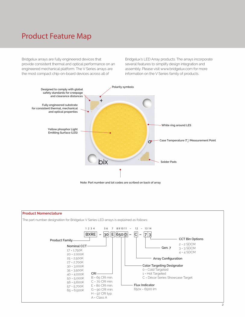
Product Feature Map
Product Nomenclature
The part number designation for Bridgelux V Series LED arrays is explained as follows:
1 2 3 4 5 6 7 8 9 10 11 – 12 – 13 14
Product Family CCT Bin Options
2 = 2 SDCM3 = 3 SDCM4 = 4 SDCM
CRIB = 65 CRI min.C = 70 CRI min.E = 80 CRI min. G = 90 CRI min.H = 97 CRI typ.A = Class A
Array Configuration
17 = 1,750K20 = 2,000K25 = 2,500K27 = 2,700K30 = 3,000K35 = 3,500K40 = 4,000K50 = 5,000K56 = 5,600K57 = 5,700K65 = 6,500K
BXRE – 30 E 650 0 – C – 7 3
Color Targeting Designator0 = Cold Targeted1 = Hot TargetedC = Décor Series Showcase Target
Gen. 7Nominal CCT
Flux Indicator650x = 6500 lm
Bridgelux arrays are fully engineered devices that provide consistent thermal and optical performance on an engineered mechanical platform. The V Series arrays are the most compact chip-on-board devices across all of
Bridgelux’s LED Array products. The arrays incorporate several features to simplify design integration and assembly. Please visit www.bridgelux.com for more information on the V Series family of products.
Fully engineered substrate for consistent thermal, mechanical
and optical properties
Yellow phosphor Light Emitting Surface (LES)
Note: Part number and lot codes are scribed on back of array
Polarity symbols
Solder Pads
White ring around LES
Case Temperature (Tc) Measurement Point
Designed to comply with global safety standards for creepage
and clearance distances

3
Product Selection Guide
The following product configurations are available:
Table 1: Selection Guide, Pulsed Measurement Data (Tj = Tc = 25°C)
Part NumberNominal
CCT1
(K)CRI2
Nominal Drive Current3
(mA)
Typical Pulsed Flux4,5,6
Tc = 25ºC(lm)
Minimum Pulsed Flux6,7
Tc = 25ºC(lm)
Typical Vf (V)
Typical Power
(W)
Typical Efficacy (lm/W)
BXRE-17E6500-D-74 1750 80 1400 4340 3906 35.0 49.0 89
BXRE-20B6501-C-73 2000 65 1440 11183 10065 52.0 74.9 149
BXRE-20B6501-D-73 2000 65 1400 7318 6586 35.0 49.0 149
BXRE-25E6500-D-74 2500 80 1400 7015 6314 35.0 49.0 143
BXRE-27E6500-B-7X 2700 80 1170 9337 8403 52.0 60.8 153
BXRE-27E6500-C-7X 2700 80 1440 11492 10343 52.0 74.9 153
BXRE-27E6500-D-7X 2700 80 1400 7520 6768 35.0 49.0 153
BXRE-27G6500-B-7X 2700 90 1170 7770 6993 52.0 60.8 128
BXRE-27G6500-C-7X 2700 90 1440 9564 8607 52.0 74.9 128
BXRE-27G6500-D-7X 2700 90 1400 6258 5632 35.0 49.0 128
BXRE-27H6500-D-7X 2700 97 1400 5451 4906 35.0 49.0 111
BXRE-30E6500-B-7X10 3000 80 1170 9713 8742 52.0 60.8 160
BXRE-30E6500-C-7X10 3000 80 1440 11955 10759 52.0 74.9 160
BXRE-30E6500-D-7X10 3000 80 1400 7823 7041 35.0 49.0 160
BXRE-30G6500-B-7X 3000 90 1170 8084 7275 52.0 60.8 133
BXRE-30G6500-C-7X 3000 90 1440 9949 8954 52.0 74.9 133
BXRE-30G6500-D-7X 3000 90 1400 6511 5860 35.0 49.0 133
BXRE-30G650C-D-73 3000 90 1400 6056 5451 35.0 49.0 124
BXRE-30H6500-D-7X 3000 97 1400 5804 5224 35.0 49.0 118
BXRE-35E6500-B-7X10 3500 80 1170 10026 9024 52.0 60.8 165
BXRE-35E6500-C-7X10 3500 80 1440 12340 11106 52.0 74.9 165
BXRE-35E6500-D-7X10 3500 80 1400 8075 7268 35.0 49.0 165
BXRE-35G6500-B-7X 3500 90 1170 8334 7501 52.0 60.8 137
BXRE-35G6500-C-7X 3500 90 1440 10258 9232 52.0 74.9 137
BXRE-35G6500-D-7X 3500 90 1400 6713 6041 35.0 49.0 137
BXRE-35A6501-D-738,9 3500 93 1400 6321 5689 35.0 49.0 129
BXRE-40E6500-B-7X10 4000 80 1170 10089 9080 52.0 60.8 166
BXRE-40E6500-C-7X10 4000 80 1440 12417 11176 52.0 74.9 166
BXRE-40E6500-D-7X10 4000 80 1400 8126 7313 35.0 49.0 166
BXRE-40G6500-B-7X 4000 90 1170 8648 7783 52.0 60.8 142
BXRE-40G6500-C-7X 4000 90 1440 10643 9579 52.0 74.9 142
BXRE-40G6500-D-7X 4000 90 1400 6965 6268 35.0 49.0 142
Notes for Table 1:1. Nominal CCT as defined by ANSI C78.377-2011. Products with a CCT of 5000K-6500K are hot targeted to Tc = 85°C.2. CRI values are typical for Décor Series Ultra and Décor Series Class A products. CRI values are minimums for all other products. Minimum R9 value for
80 CRI products is 0, the minimum R9 values for 90 CRI products is 50, the minimum R9 values for 97 CRI products is 93. Bridgelux maintains a ± 3 tolerance on R9 values.
3. Drive current is referred to as nominal drive current. 4. Products tested under pulsed condition (10ms pulse width) at nominal test current where Tj (junction temperature) = Tc (case temperature) = 25°C. 5. Typical performance values are provided as a reference only and are not a guarantee of performance. 6. Bridgelux maintains a ±7% tolerance on flux measurements. 7. Minimum flux values at the nominal test current are guaranteed by 100% test. 8. Nominal CCT is defined by the Lighting Research Center’s Class A definition. The center of the Class A color bin is on the corresponding isothermal line.9. GAI value is 80. To help ensure optimal fixture level performance, GAI is measured at the fixture level, on axis, at a case temperature of 70°C. GAI may
vary depending on fixture design and performance.10. SKUs meet DLC premium (Outdoor Mid Output) requirements under certain system level conditions.

4
Product Selection Guide
Table 1: Selection Guide, Pulsed Measurement Data (Tj = Tc = 25°C) (continued)
Part NumberNominal
CCT1 (K)
CRI2 Nominal Drive
Current3 (mA)
Typical Pulsed Flux4,5,6
Tc = 25ºC(lm)
Minimum Pulsed Flux6,7
Tc = 25ºC(lm)
Typical Vf (V)
Typical Power
(W)
Typical Efficacy (lm/W)
BXRE-50C6501-B-7x10 5000 70 1170 11092 9983 52.0 60.8 182
BXRE-50C6501-C-7x10 5000 70 1440 13651 12286 52.0 74.9 182
BXRE-50C6501-D-7x10 5000 70 1400 8933 8040 35.0 49.0 182
BXRE-50E6501-B-7x10 5000 80 1170 10402 9362 52.0 60.8 171
BXRE-50E6501-C-7x10 5000 80 1440 12803 11523 52.0 74.9 171
BXRE-50E6501-D-7x10 5000 80 1400 8378 7540 35.0 49.0 171
BXRE-50G6501-B-7x 5000 90 1170 8836 7952 52.0 60.8 145
BXRE-50G6501-C-7x 5000 90 1440 10875 9787 52.0 74.9 145
BXRE-50G6501-D-7x 5000 90 1400 7116 6405 35.0 49.0 145
BXRE-56G6501-D-74 5600 90 1400 7470 6723 35.0 49.0 152
BXRE-57C6501-B-7x10 5700 70 1170 10716 9644 52.0 60.8 176
BXRE-57C6501-C-7x10 5700 70 1440 13189 11870 52.0 74.9 176
BXRE-57C6501-D-7x10 5700 70 1400 8630 7767 35.0 49.0 176
BXRE-57E6501-B-7x10 5700 80 1170 10282 9254 52.0 60.8 169
BXRE-57E6501-C-7x10 5700 80 1440 12655 11389 52.0 74.9 169
BXRE-57E6501-D-7x10 5700 80 1400 8281 7453 35.0 49.0 169
BXRE-65C6501-B-7x10 6500 70 1170 10904 9813 52.0 60.8 179
BXRE-65C6501-C-7x10 6500 70 1440 13420 12078 52.0 74.9 179
BXRE-65C6501-D-7x10 6500 70 1400 8782 7904 35.0 49.0 179
BXRE-65E6501-B-7x10 6500 80 1170 10464 9418 52.0 60.8 172
BXRE-65E6501-C-7x10 6500 80 1440 12879 11591 52.0 74.9 172
BXRE-65E6501-D-7x10 6500 80 1400 8428 7585 35.0 49.0 172
Notes for Table 1:1. Nominal CCT as defined by ANSI C78.377-2011. Products with a CCT of 5000K-6500K are hot targeted to Tc = 85°C.2. CRI values are typical for Décor Series Ultra and Décor Series Class A products. CRI values are minimums for all other products. Minimum R9 value for 80
CRI products is 0, the minimum R9 values for 90 CRI products is 50, the minimum R9 values for 97 CRI products is 93. Bridgelux maintains a ± 3 tolerance on R9 values.
3. Drive current is referred to as nominal drive current. 4. Products tested under pulsed condition (10ms pulse width) at nominal test current where Tj (junction temperature) = Tc (case temperature) = 25°C. 5. Typical performance values are provided as a reference only and are not a guarantee of performance. 6. Bridgelux maintains a ±7% tolerance on flux measurements. 7. Minimum flux values at the nominal test current are guaranteed by 100% test. 8. Nominal CCT is defined by the Lighting Research Center’s Class A definition. The center of the Class A color bin is on the corresponding isothermal line.9. GAI value is 80. To help ensure optimal fixture level performance, GAI is measured at the fixture level, on axis, at a case temperature of 70°C. GAI may vary
depending on fixture design and performance.10. SKUs meet DLC premium (Outdoor Mid Output) requirements under certain system level conditions.

5
Product Selection Guide
Table 2: Selection Guide, Stabilized DC Performance (Tc = 70°C) 7,8
Part NumberNominal
CCT1 (K)
GAI2 CRI3 Nominal Drive
Current4 (mA)
Typical DC Flux5,6
Tc = 70ºC(lm)
Minimum DC Flux6,9
Tc = 70ºC(lm)
Typical Vf (V)
Typical Power
(W)
Typical Efficacy (lm/W)
BXRE-35A6501-D-73 3500 80 93 1400 5879 5291 33.4 46.8 126
Notes for Table 2:
1. Nominal CCT is defined by the Lighting Research Center’s Class A definition. The center of the Class A color bin is on the corresponding isothermal line.
2. To help ensure optimal fixture level performance, GAI is measured at the fixture level, on axis, at a case temperature of 70°C. GAI may vary depending on fixture design and performance.
3. All CRI values are measured at Tj = Tc = 25°C. CRI Values are specified as typical.
4. Drive current is referred to as nominal drive current.
5. Typical performance values are provided as a reference only and are not a guarantee of performance.
6. Bridgelux maintains a ±7% tolerance on flux measurements.
7. Typical stabilized DC performance values are provided as reference only and are not a guarantee of performance.
8. Typical performance is estimated based on operation under DC (direct current) with LED array mounted onto a heat sink with thermal interface material and the case temperature maintained at specified temperature. Based on Bridgelux test setup, values may vary depending on the thermal design of the luminaire and/or the exposed environment to which the product is subjected.
9. Minimum flux values at elevated temperatures are provided for reference only and are not guaranteed by 100% production testing. Based on Bridgelux test setup, values may vary depending on the thermal design of the luminaire and/or the exposed environment to which the product is subjected.

6
Product Selection Guide
Table 3: Selection Guide, Stabilized DC Performance (Tc = 85°C) 4,5
Part Number Nominal CCT1 (K) CRI2
Nominal Drive Current3
(mA)
Typical DC Flux4,5
Tc = 85ºC(lm)
Minimum DC Flux6
Tc = 85ºC(lm)
Typical Vf (V)
Typical Power
(W)
Typical Efficacy (lm/W)
BXRE-17E6500-D-74 1750 80 1400 3906 3516 33.4 46.8 84
BXRE-20B6501-C-73 2000 65 1440 10065 9058 50.7 73.0 138
BXRE-20B6501-D-73 2000 65 1400 6586 5928 33.4 46.8 141
BXRE-25E6500-D-74 2500 80 1400 6314 5682 33.4 46.8 135
BXRE-27E6500-B-7X 2700 80 1170 8403 7563 50.7 59.3 142
BXRE-27E6500-C-7X 2700 80 1440 10343 9308 50.7 73.0 142
BXRE-27E6500-D-7X 2700 80 1400 6768 6091 33.4 46.8 145
BXRE-27G6500-B-7X 2700 90 1170 6993 6294 50.7 59.3 118
BXRE-27G6500-C-7X 2700 90 1440 8607 7747 50.7 73.0 118
BXRE-27G6500-D-7X 2700 90 1400 5632 5069 33.4 46.8 120
BXRE-27H6500-D-7X 2700 97 1400 4906 4415 33.4 46.8 105
BXRE-30E6500-B-7X 3000 80 1170 8742 7868 50.7 59.3 147
BXRE-30E6500-C-7X 3000 80 1440 10759 9683 50.7 73.0 147
BXRE-30E6500-D-7X 3000 80 1400 7041 6337 33.4 46.8 151
BXRE-30G6500-B-7X 3000 90 1170 7275 6548 50.7 59.3 123
BXRE-30G6500-C-7X 3000 90 1440 8954 8059 50.7 73.0 123
BXRE-30G6500-D-7X 3000 90 1400 5860 5274 33.4 46.8 125
BXRE-30G650C-D-73 3000 90 1400 5451 4906 33.4 46.8 117
BXRE-30H6500-D-7X 3000 97 1400 5224 4701 33.4 46.8 112
BXRE-35E6500-B-7X 3500 80 1170 9024 8121 50.7 59.3 152
BXRE-35E6500-C-7X 3500 80 1440 11106 9996 50.7 73.0 152
BXRE-35E6500-D-7X 3500 80 1400 7268 6541 33.4 46.8 155
BXRE-35G6500-B-7X 3500 90 1170 7501 6751 50.7 59.3 127
BXRE-35G6500-C-7X 3500 90 1440 9232 8309 50.7 73.0 127
BXRE-35G6500-D-7X 3500 90 1400 6041 5437 33.4 46.8 129
BXRE-35A6501-D-737,8 3500 93 1400 5689 5120 33.4 46.8 122
BXRE-40E6500-B-7X 4000 80 1170 9080 8172 50.7 59.3 153
BXRE-40E6500-C-7X 4000 80 1440 11176 10058 50.7 73.0 153
BXRE-40E6500-D-7X 4000 80 1400 7313 6582 33.4 46.8 156
BXRE-40G6500-B-7X 4000 90 1170 7783 7005 50.7 59.3 131
BXRE-40G6500-C-7X 4000 90 1440 9579 8621 50.7 73.0 131
BXRE-40G6500-D-7X 4000 90 1400 6268 5642 33.4 46.8 134
Notes for Table 3:1. Nominal CCT as defined by ANSI C78.377-2011. Products with a CCT of 5000K-6500K are hot targeted to Tc = 85°C. 2. All CRI values are measured at Tj = Tc = 25°C. CRI values are typical for Décor Series Ultra and Décor Series Class A products. CRI values are minimums
for all other products. Minimum R9 value for 80 CRI products is 0, the minimum R9 values for 90 CRI products is 50, the minimum R9 values for 97 CRI products is 93. Bridgelux maintains a ± 3 tolerance on R9 values.
3. Drive current is referred to as nominal drive current. 4. Typical stabilized DC performance values are provided as reference only and are not a guarantee of performance. 5. Typical performance is estimated based on operation under DC (direct current) with LED array mounted onto a heat sink with thermal interface
material and the case temperature maintained at 85°C. Based on Bridgelux test setup, values may vary depending on the thermal design of the luminaire and/or the exposed environment to which the product is subjected.
6. Minimum flux values at elevated temperatures are provided for reference only and are not guaranteed by 100% production testing. Based on Bridgelux test setup, values may vary depending on the thermal design of the luminaire and/or the exposed environment to which the product is subjected.
7. Nominal CCT is defined by the Lighting Research Center’s Class A definition. The center of the Class A color bin is on the corresponding isothermal line.8. GAI value is 80. To help ensure optimal fixture level performance, GAI is measured at the fixture level, on axis, at a case temperature of 70°C. GAI may
vary depending on fixture design and performance.

7
Product Selection Guide
Table 3: Selection Guide, Stabilized DC Performance (Tc = 85°C) 4,5 (continued)
Part Number Nominal CCT1 (K) CRI2
Nominal Drive Current3
(mA)
Typical DC Flux4,5
Tc = 85ºC(lm)
Minimum DC Flux6
Tc = 85ºC(lm)
Typical Vf (V)
Typical Power
(W)
Typical Efficacy (lm/W)
BXRE-50C6501-B-7x 5000 70 1170 9983 8984 50.7 59.3 168
BXRE-50C6501-C-7x 5000 70 1440 12286 11058 50.7 73.0 168
BXRE-50C6501-D-7x 5000 70 1400 8040 7236 33.4 46.8 172
BXRE-50E6501-B-7x 5000 80 1170 9362 8426 50.7 59.3 158
BXRE-50E6501-C-7x 5000 80 1440 11523 10370 50.7 73.0 158
BXRE-50E6501-D-7x 5000 80 1400 7540 6786 33.4 46.8 161
BXRE-50G6501-B-7x 5000 90 1170 7952 7157 50.7 59.3 134
BXRE-50G6501-C-7x 5000 90 1440 9787 8809 50.7 73.0 134
BXRE-50G6501-D-7x 5000 90 1400 6405 5764 33.4 46.8 137
BXRE-56G6501-D-74 5600 90 1400 6723 6050 33.4 46.8 144
BXRE-57C6501-B-7x 5700 70 1170 9644 8680 50.7 59.3 163
BXRE-57C6501-C-7x 5700 70 1440 11870 10683 50.7 73.0 163
BXRE-57C6501-D-7x 5700 70 1400 7767 6991 33.4 46.8 166
BXRE-57E6501-B-7x 5700 80 1170 9254 8328 50.7 59.3 156
BXRE-57E6501-C-7x 5700 80 1440 11389 10250 50.7 73.0 156
BXRE-57E6501-D-7x 5700 80 1400 7453 6708 33.4 46.8 159
BXRE-65C6501-B-7x 6500 70 1170 9813 8832 50.7 59.3 166
BXRE-65C6501-C-7x 6500 70 1440 12078 10870 50.7 73.0 166
BXRE-65C6501-D-7x 6500 70 1400 7904 7113 33.4 46.8 169
BXRE-65E6501-B-7x 6500 80 1170 9418 8476 50.7 59.3 159
BXRE-65E6501-C-7x 6500 80 1440 11591 10432 50.7 73.0 159
BXRE-65E6501-D-7x 6500 80 1400 7585 6827 33.4 46.8 162
Notes for Table 3:1. Nominal CCT as defined by ANSI C78.377-2011. Products with a CCT of 5000K-6500K are hot targeted to Tc = 85°C. 2. All CRI values are measured at Tj = Tc = 25°C. CRI values are typical for Décor Series Ultra and Décor Series Class A products. CRI values are minimums
for all other products. Minimum R9 value for 80 CRI products is 0, the minimum R9 values for 90 CRI products is 50, the minimum R9 values for 97 CRI products is 93. Bridgelux maintains a ± 3 tolerance on R9 values.
3. Drive current is referred to as nominal drive current. 4. Typical stabilized DC performance values are provided as reference only and are not a guarantee of performance. 5. Typical performance is estimated based on operation under DC (direct current) with LED array mounted onto a heat sink with thermal interface
material and the case temperature maintained at 85°C. Based on Bridgelux test setup, values may vary depending on the thermal design of the luminaire and/or the exposed environment to which the product is subjected.
6. Minimum flux values at elevated temperatures are provided for reference only and are not guaranteed by 100% production testing. Based on Bridgelux test setup, values may vary depending on the thermal design of the luminaire and/or the exposed environment to which the product is subjected.
7. Nominal CCT is defined by the Lighting Research Center’s Class A definition. The center of the Class A color bin is on the corresponding isothermal line.8. GAI value is 80. To help ensure optimal fixture level performance, GAI is measured at the fixture level, on axis, at a case temperature of 70°C. GAI may vary
depending on fixture design and performance.

8
Performance at Commonly Used Drive Currents
V Series LED arrays are tested to the specifications shown using the nominal drive currents in Table 1. V Series may also
be driven at other drive currents dependent on specific application design requirements. The performance at any
drive current can be derived from the current vs. voltage characteristics shown in Figures 1, 2 & 3 and the flux vs. current
characteristics shown in Figures 4, 5 & 6. The performance at commonly used drive currents is summarized in Table 4.
Table 4: Product Performance at Commonly Used Drive Currents
Part Number CRIDrive
Current1
(mA)
Typical Vf Tc = 25ºC
(V)
Typical Power
Tc = 25ºC(W)
Typical Flux2
Tc = 25ºC(lm)
Typical DC Flux3 Tc = 85ºC
(lm)
Typical Efficacy Tc = 25ºC(lm/W)
BXRE-17E6500-D-74 80
700 33.2 23.3 2241 2065 961050 34.2 35.9 3301 3028 921400 35.0 49.0 4340 3906 892100 36.4 76.5 6276 5637 822800 37.7 105.6 8082 7185 77
BXRE-20B6501-C-73 65
720 49.6 35.7 6243 5301 175960 50.5 48.5 7941 6946 1641440 52.0 74.9 11183 10065 1492160 54.2 117.0 15660 14397 1342880 55.9 161.1 19673 18249 122
BXRE-20B6501-D-73 65
700 33.2 23.3 3778 3482 1621050 34.2 35.9 5566 5105 1551400 35.0 49.0 7318 6586 1492100 36.4 76.5 10581 9505 1382800 37.7 105.6 13626 12114 129
BXRE-25E6500-D-74 80
700 33.2 23.3 3622 3337 1561050 34.2 35.9 5336 4893 1481400 35.0 49.0 7015 6314 1432100 36.4 76.5 10143 9112 1332800 37.7 105.6 13062 11612 124
BXRE-27E6500-B-7X 80
585 49.6 29.0 4996 4622 172780 50.5 39.4 6486 5930 1651170 52.0 60.8 9337 8403 1531755 54.3 95.3 13294 11828 1402340 56.2 131.5 16868 14856 128
BXRE-27E6500-C-7X 80
720 49.6 35.7 6415 5448 179960 50.5 48.5 8160 7138 1681440 52.0 74.9 11492 10343 1532160 54.2 117.0 16092 14794 1382880 55.9 161.1 20216 18752 125
BXRE-27E6500-D-7X 80
700 33.2 23.3 3882 3578 1671050 34.2 35.9 5720 5246 1591400 35.0 49.0 7520 6768 1532100 36.4 76.5 10873 9767 1422800 37.7 105.6 14002 12448 133
BXRE-27G6500-B-7X 90
585 49.6 29.0 4158 3847 143780 50.5 39.4 5398 4935 1371170 52.0 60.8 7770 6993 1281755 54.3 95.3 11064 9843 1162340 56.2 131.5 14038 12363 107
Notes for Table 4:1. Alternate drive currents are provided for reference only and are not a guarantee of performance.2. Bridgelux maintains a ± 7% tolerance on flux measurements.3. Typical stabilized DC performance values are provided as reference only and are not a guarantee of performance.

9
Performance at Commonly Used Drive Currents
Table 4: Product Performance at Commonly Used Drive Currents (Continued)
Part Number CRIDrive
Current1
(mA)
Typical Vf Tc = 25ºC
(V)
Typical Power
Tc = 25ºC(W)
Typical Flux2
Tc = 25ºC(lm)
Typical DC Flux3 Tc = 85ºC
(lm)
Typical Efficacy Tc = 25ºC(lm/W)
BXRE-27G6500-C-7X 90
720 49.6 35.7 5338 4534 149960 50.5 48.5 6791 5940 1401440 52.0 74.9 9564 8607 1282160 54.2 117.0 13392 12312 1142880 55.9 161.1 16824 15606 104
BXRE-27G6500-D-7X 90
700 33.2 23.3 3231 2977 1391050 34.2 35.9 4760 4365 1321400 35.0 49.0 6258 5632 1282100 36.4 76.5 9048 8128 1182800 37.7 105.6 11653 10359 110
BXRE-27H6500-D-7X 97
700 33.2 23.3 2814 2593 1211050 34.2 35.9 4146 3802 1151400 35.0 49.0 5451 4906 1112100 36.4 76.5 7881 7080 1032800 37.7 105.6 10149 9023 96
BXRE-30E6500-B-7X 80
585 49.6 29.0 5197 4808 179780 50.5 39.4 6747 6168 1711170 52.0 60.8 9713 8742 1601755 54.3 95.3 13830 12304 1452340 56.2 131.5 17548 15454 133
BXRE-30E6500-C-7X 80
720 49.6 35.7 6673 5667 187960 50.5 48.5 8489 7425 1751440 52.0 74.9 11955 10759 1602160 54.2 117.0 16740 15390 1432880 55.9 161.1 21030 19507 131
BXRE-30E6500-D-7X 80
700 33.2 23.3 4039 3722 1741050 34.2 35.9 5950 5457 1661400 35.0 49.0 7823 7041 1602100 36.4 76.5 11311 10160 1482800 37.7 105.6 14566 12949 138
BXRE-30G6500-B-7X 90
585 49.6 29.0 4326 4002 149780 50.5 39.4 5615 5134 1431170 52.0 60.8 8084 7275 1331755 54.3 95.3 11510 10240 1212340 56.2 131.5 14604 12862 111
BXRE-30G6500-C-7X 90
720 49.6 35.7 5554 4716 155960 50.5 48.5 7065 6180 1461440 52.0 74.9 9949 8954 1332160 54.2 117.0 13932 12808 1192880 55.9 161.1 17502 16235 109
BXRE-30G6500-D-7X 90
700 33.2 23.3 3361 3097 1441050 34.2 35.9 4952 4541 1381400 35.0 49.0 6511 5860 1332100 36.4 76.5 9413 8456 1232800 37.7 105.6 12123 10777 115
Notes for Table 4:1. Alternate drive currents are provided for reference only and are not a guarantee of performance.2. Bridgelux maintains a ± 7% tolerance on flux measurements.3. Typical stabilized DC performance values are provided as reference only and are not a guarantee of performance.

10
Table 4: Product Performance at Commonly Used Drive Currents (Continued)
Part Number CRIDrive
Current1
(mA)
Typical Vf Tc = 25ºC
(V)
Typical Power
Tc = 25ºC(W)
Typical Flux2
Tc = 25ºC(lm)
Typical DC Flux3 Tc = 85ºC
(lm)
Typical Efficacy Tc = 25ºC(lm/W)
BXRE-30G650C-D-73 90
700 33.2 23.3 3127 2881 1341050 34.2 35.9 4607 4225 1281400 35.0 49.0 6056 5451 1232100 36.4 76.5 8757 7866 1142800 37.7 105.6 11277 10025 107
BXRE-30H6500-D-7X 97
700 33.2 23.3 2996 2761 1291050 34.2 35.9 4415 4049 1231400 35.0 49.0 5804 5224 1182100 36.4 76.5 8392 7538 1102800 37.7 105.6 10807 9607 102
BXRE-35E6500-B-7X 80
585 49.6 29.0 5365 4963 185780 50.5 39.4 6965 6367 1771170 52.0 60.8 10026 9024 1651755 54.3 95.3 14276 12701 1502340 56.2 131.5 18114 15952 138
BXRE-35E6500-C-7X 80
720 49.6 35.7 6888 5850 193960 50.5 48.5 8762 7665 1811440 52.0 74.9 12340 11106 1652160 54.2 117.0 17280 15886 1482880 55.9 161.1 21708 20137 135
BXRE-35E6500-D-7X 80
700 33.2 23.3 4169 3842 1791050 34.2 35.9 6142 5633 1711400 35.0 49.0 8075 7268 1652100 36.4 76.5 11675 10488 1532800 37.7 105.6 15036 13367 142
BXRE-35G6500-B-7X 90
585 49.6 29.0 4460 4126 154780 50.5 39.4 5789 5293 1471170 52.0 60.8 8334 7501 1371755 54.3 95.3 11867 10558 1252340 56.2 131.5 15057 13260 115
BXRE-35G6500-C-7X 90
720 49.6 35.7 5726 4863 160960 50.5 48.5 7284 6371 1501440 52.0 74.9 10258 9232 1372160 54.2 117.0 14364 13205 1232880 55.9 161.1 18045 16739 112
BXRE-35G6500-D-7X 90
700 33.2 23.3 3465 3193 1491050 34.2 35.9 5106 4682 1421400 35.0 49.0 6713 6041 1372100 36.4 76.5 9705 8718 1272800 37.7 105.6 12499 11111 118
BXRE-35A6501-D-73 93
700 33.2 23.3 3263 3007 1401050 34.2 35.9 4808 4409 1341400 35.0 49.0 6321 5689 1292100 36.4 76.5 9139 8210 1192800 37.7 105.6 11770 10463 111
Performance at Commonly Used Drive Currents
Notes for Table 4:1. Alternate drive currents are provided for reference only and are not a guarantee of performance.2. Bridgelux maintains a ± 7% tolerance on flux measurements.3. Typical stabilized DC performance values are provided as reference only and are not a guarantee of performance.
11
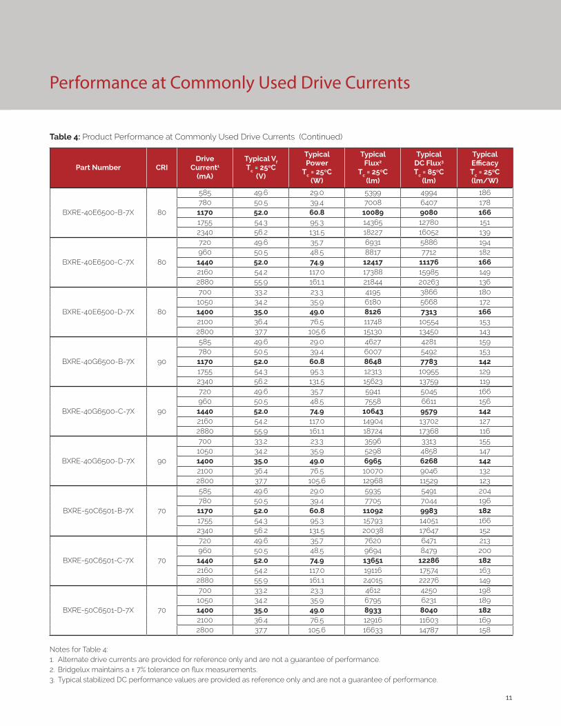
Performance at Commonly Used Drive Currents
Table 4: Product Performance at Commonly Used Drive Currents (Continued)
Part Number CRIDrive
Current1
(mA)
Typical Vf Tc = 25ºC
(V)
Typical Power
Tc = 25ºC(W)
Typical Flux2
Tc = 25ºC(lm)
Typical DC Flux3 Tc = 85ºC
(lm)
Typical Efficacy Tc = 25ºC(lm/W)
BXRE-40E6500-B-7X 80
585 49.6 29.0 5399 4994 186780 50.5 39.4 7008 6407 1781170 52.0 60.8 10089 9080 1661755 54.3 95.3 14365 12780 1512340 56.2 131.5 18227 16052 139
BXRE-40E6500-C-7X 80
720 49.6 35.7 6931 5886 194960 50.5 48.5 8817 7712 1821440 52.0 74.9 12417 11176 1662160 54.2 117.0 17388 15985 1492880 55.9 161.1 21844 20263 136
BXRE-40E6500-D-7X 80
700 33.2 23.3 4195 3866 1801050 34.2 35.9 6180 5668 1721400 35.0 49.0 8126 7313 1662100 36.4 76.5 11748 10554 1532800 37.7 105.6 15130 13450 143
BXRE-40G6500-B-7X 90
585 49.6 29.0 4627 4281 159780 50.5 39.4 6007 5492 1531170 52.0 60.8 8648 7783 1421755 54.3 95.3 12313 10955 1292340 56.2 131.5 15623 13759 119
BXRE-40G6500-C-7X 90
720 49.6 35.7 5941 5045 166960 50.5 48.5 7558 6611 1561440 52.0 74.9 10643 9579 1422160 54.2 117.0 14904 13702 1272880 55.9 161.1 18724 17368 116
BXRE-40G6500-D-7X 90
700 33.2 23.3 3596 3313 1551050 34.2 35.9 5298 4858 1471400 35.0 49.0 6965 6268 1422100 36.4 76.5 10070 9046 1322800 37.7 105.6 12968 11529 123
BXRE-50C6501-B-7X 70
585 49.6 29.0 5935 5491 204780 50.5 39.4 7705 7044 1961170 52.0 60.8 11092 9983 1821755 54.3 95.3 15793 14051 1662340 56.2 131.5 20038 17647 152
BXRE-50C6501-C-7X 70
720 49.6 35.7 7620 6471 213960 50.5 48.5 9694 8479 2001440 52.0 74.9 13651 12286 1822160 54.2 117.0 19116 17574 1632880 55.9 161.1 24015 22276 149
BXRE-50C6501-D-7X 70
700 33.2 23.3 4612 4250 1981050 34.2 35.9 6795 6231 1891400 35.0 49.0 8933 8040 1822100 36.4 76.5 12916 11603 1692800 37.7 105.6 16633 14787 158
Notes for Table 4:1. Alternate drive currents are provided for reference only and are not a guarantee of performance.2. Bridgelux maintains a ± 7% tolerance on flux measurements.3. Typical stabilized DC performance values are provided as reference only and are not a guarantee of performance.

12
Performance at Commonly Used Drive Currents
Table 4: Product Performance at Commonly Used Drive Currents (Continued)
Part Number CRIDrive
Current1
(mA)
Typical Vf Tc = 25ºC
(V)
Typical Power
Tc = 25ºC(W)
Typical Flux2
Tc = 25ºC(lm)
Typical DC Flux3 Tc = 85ºC
(lm)
Typical Efficacy Tc = 25ºC(lm/W)
BXRE-50E6501-B-7X 80
585 49.6 29.0 5566 5149 192780 50.5 39.4 7226 6606 1831170 52.0 60.8 10402 9362 1711755 54.3 95.3 14811 13177 1552340 56.2 131.5 18793 16551 143
BXRE-50E6501-C-7X 80
720 49.6 35.7 7147 6069 200960 50.5 48.5 9091 7952 1881440 52.0 74.9 12803 11523 1712160 54.2 117.0 17928 16482 1532880 55.9 161.1 22523 20892 140
BXRE-50E6501-D-7X 80
700 33.2 23.3 4325 3986 1861050 34.2 35.9 6372 5844 1771400 35.0 49.0 8378 7540 1712100 36.4 76.5 12113 10882 1582800 37.7 105.6 15600 13868 148
BXRE-50G6501-B-7X 90
585 49.6 29.0 4728 4374 163780 50.5 39.4 6138 5611 1561170 52.0 60.8 8836 7952 1451755 54.3 95.3 12581 11193 1322340 56.2 131.5 15963 14058 121
BXRE-50G6501-C-7X 90
720 49.6 35.7 6070 5155 170960 50.5 48.5 7722 6754 1591440 52.0 74.9 10875 9787 1452160 54.2 117.0 15228 14000 1302880 55.9 161.1 19131 17745 119
BXRE-50G6501-D-7X 90
700 33.2 23.3 3674 3385 1581050 34.2 35.9 5413 4964 1511400 35.0 49.0 7116 6405 1452100 36.4 76.5 10289 9243 1342800 37.7 105.6 13250 11779 125
BXRE-56G6501-D-74 90
700 33.2 23.3 3856 3554 1661050 34.2 35.9 5681 5210 1581400 35.0 49.0 7470 6723 1522100 36.4 76.5 10800 9702 1412800 37.7 105.6 13908 12364 132
BXRE-57C6501-B-7X 70
585 49.6 29.0 5734 5305 197780 50.5 39.4 7443 6805 1891170 52.0 60.8 10716 9644 1761755 54.3 95.3 15257 13574 1602340 56.2 131.5 19359 17049 147
BXRE-57C6501-C-7X 70
720 49.6 35.7 7362 6252 206960 50.5 48.5 9365 8192 1931440 52.0 74.9 13189 11870 1762160 54.2 117.0 18468 16978 1582880 55.9 161.1 23201 21521 144
BXRE-57C6501-D-7X 70
700 33.2 23.3 4455 4106 1911050 34.2 35.9 6564 6020 1831400 35.0 49.0 8630 7767 1762100 36.4 76.5 12478 11209 1632800 37.7 105.6 16070 14286 152

13
Performance at Commonly Used Drive Currents
Table 4: Product Performance at Commonly Used Drive Currents (Continued)
Part Number CRIDrive
Current1
(mA)
Typical Vf Tc = 25ºC
(V)
Typical Power
Tc = 25ºC(W)
Typical Flux2
Tc = 25ºC(lm)
Typical DC Flux3 Tc = 85ºC
(lm)
Typical Efficacy Tc = 25ºC(lm/W)
BXRE-57E6501-B-7X 80
585 49.6 29.0 5502 5090 189780 50.5 39.4 7142 6530 1811170 52.0 60.8 10282 9254 1691755 54.3 95.3 14640 13025 1542340 56.2 131.5 18575 16359 141
BXRE-57E6501-C-7X 80
720 49.6 35.7 7064 5999 198960 50.5 48.5 8986 7860 1851440 52.0 74.9 12655 11389 1692160 54.2 117.0 17721 16291 1512880 55.9 161.1 22262 20650 138
BXRE-57E6501-D-74 80
700 33.2 23.3 4275 3940 1841050 34.2 35.9 6299 5776 1751400 35.0 49.0 8281 7453 1692100 36.4 76.5 11973 10756 1562800 37.7 105.6 15419 13707 146
BXRE-65C6501-B-7X 70
585 49.6 29.0 5835 5398 201780 50.5 39.4 7574 6924 1921170 52.0 60.8 10904 9813 1791755 54.3 95.3 15525 13812 1632340 56.2 131.5 19699 17348 150
BXRE-65C6501-C-7X 70
720 49.6 35.7 7491 6362 210960 50.5 48.5 9529 8335 1971440 52.0 74.9 13420 12078 1792160 54.2 117.0 18792 17276 1612880 55.9 161.1 23608 21899 147
BXRE-65C6501-D-7X 70
700 33.2 23.3 4534 4178 1951050 34.2 35.9 6679 6126 1861400 35.0 49.0 8782 7904 1792100 36.4 76.5 12697 11406 1662800 37.7 105.6 16351 14536 155
BXRE-65E6501-B-7X 80
585 49.6 29.0 5600 5180 193780 50.5 39.4 7269 6646 1851170 52.0 60.8 10464 9418 1721755 54.3 95.3 14900 13256 1562340 56.2 131.5 18905 16649 144
BXRE-65E6501-C-7X 80
720 49.6 35.7 7189 6105 201960 50.5 48.5 9145 7999 1891440 52.0 74.9 12879 11591 1722160 54.2 117.0 18035 16580 1542880 55.9 161.1 22657 21016 141
BXRE-65E6501-D-7X 80
700 33.2 23.3 4351 4010 1871050 34.2 35.9 6410 5879 1781400 35.0 49.0 8428 7585 1722100 36.4 76.5 12185 10946 1592800 37.7 105.6 15693 13951 149
Notes for Table 4:1. Alternate drive currents are provided for reference only and are not a guarantee of performance.2. Bridgelux maintains a ± 7% tolerance on flux measurements.3. Typical stabilized DC performance values are provided as reference only and are not a guarantee of performance.

14
Electrical Characteristics
Table 5: Electrical Characteristics
Part NumberDrive Current
(mA)
Forward VoltagePulsed, Tc = 25ºC (V) 1, 2, 3, 8 Typical
Coefficient of Forward
Voltage4 ∆Vf/∆Tc
(mV/ºC)
Typical Thermal
Resistance Junction to Case5,6
Rj-c (ºC/W)
Driver Selection Voltages7
(V)
Minimum Typical MaximumVf Min.
Hot Tc = 105ºC
(V)
Vf Max. Cold
Tc = -40ºC (V)
BXRE-xxx650x-B-7x1170 48.1 52.0 55.9 -22.1 0.07 46.3 57.3
2340 52.0 56.2 60.4 -22.1 0.09 50.2 61.8
BXRE-xxx650x-C-7x1440 48.1 52.0 55.9 -22.1 0.06 46.3 57.3
2880 51.7 55.9 60.1 -22.1 0.08 50.0 61.6
BXRE-xxx650x-D-7x1400 32.4 35.0 37.6 -22.1 0.07 30.6 39.1
2800 35.0 37.7 40.4 -22.1 0.08 33.2 41.8
Notes for Table 5:
1. Parts are tested in pulsed conditions, Tc = 25°C. Pulse width is 10ms.
2. Voltage minimum and maximum are provided for reference only and are not a guarantee of performance.
3. Bridgelux maintains a tester tolerance of ± 0.10V on forward voltage measurements.
4. Typical coefficient of forward voltage tolerance is ± 0.1mV for nominal current.
5. Thermal resistance values are based from test data of a 3000K 80 CRI product.
6. Thermal resistance value was calculated using total electrical input power; optical power was not subtracted from input power. The thermal interface material used during testing is not included in the thermal resistance value.
7. Vf min hot and max cold values are provided as reference only and are not guaranteed by test. These values are provided to aid in driver design and selection over the operating range of the product.
8. This product has been designed and manufactured per IEC 62031:2014. This product has passed dielectric withstand voltage testing at 1160 V. The working voltage designated for the insulation is 80V d.c. The maximum allowable voltage across the array must be determined in the end product application.

15
Eye Safety
Table 6: Eye Safety Risk Group (RG) Classifications
Part NumberDrive
Current 5
(mA)
CCT1,5
2700K/3000K 4000K2 5000K3 6500K4
BXRE-xxx650x-B-7x
1170 RG1 RG1 RG1 RG1
1755 RG1 RG1 RG2 RG2
2340 RG1 RG2 RG2 RG2
BXRE-xxx650x-C-7x
1440 RG1 RG1 RG1 RG2
2160 RG1 RG1 RG2 RG2
2880 RG1 RG2 RG2 RG2
BXRE-xxx650x-D-7x
1400 RG1 RG1 RG1 RG1
2100 RG1 RG1 RG1 RG2
2800 RG1 RG1 RG2 RG2
Notes for Table 6:1. Eye safety classification for the use of Bridgelux V Series LED arrays is in accordance with specification IEC/TR 62778: Application of IEC 62471 for the
assessment of blue light hazard to light sources and luminaires.2. For products classified as RG2 at 4000K, Ethr= 1847.5 lx.3. For products classified as RG2 at 5000K Ethr= 1315.8 lx.4. For products classified as RG2 at 6500K, Ethr= 1124.5 lx.5. Please contact your Bridgelux sales representative for Ethr values at specific drive currents and CCTs not listed.

16
Absolute Maximum Ratings
Parameter Maximum Rating
LED Junction Temperature (Tj) 125°C
Storage Temperature -40°C to +105°C
Operating Case Temperature1 (Tc) 105°C
Soldering Temperature2 300°C or lower for a maximum of 6 seconds
BXRE-xxx650x-B-7x BXRE-xxx650x-C-7x BXRE-xxx650x-D-7x
Maximum Drive Current3 2340mA 2880mA 2800mA
Maximum Peak Pulsed Drive Current4 3340mA 4110mA 4000mA
Maximum Reverse Voltage5 -90V -90V -60V
Notes for Table 7:
1. For IEC 62717 requirement, please consult your Bridgelux sales representative.
2. Refer to Bridgelux Application Note AN101: Handling and Assembly of Bridgelux V Series LED Arrays
3. Arrays may be driven at higher currents however lumen maintenance may be reduced.
4. Bridgelux recommends a maximum duty cycle of 10% and pulse width of 20 ms when operating LED Arrays at maximum peak pulsed current specified. Maximum peak pulsed currents indicate values where LED Arrays can be driven without catastrophic failures.
5. Light emitting diodes are not designed to be driven in reverse voltage and will not produce light under this condition. Maximum rating provided for reference only.
Table 7: Maximum Ratings

17
Performance Curves
Figure 3: V22D Drive Current vs. Voltage Figure 4: V22B Typical Relative Flux vs. Current
Notes for Figures 1-6:
1. Bridgelux does not recommend driving high power LEDs at low currents. Doing so may produce unpredictable results. Pulse width modulation (PWM) is recommended for dimming effects.
2. Products tested under pulsed condition (10ms pulse width) at nominal test current where Tj (junction temperature) = Tc (case temperature) = 25°C.
Figure 1: V22B Drive Current vs. Voltage Figure 2: V22C Drive Current vs. Voltage
Figure 5: V22C Typical Relative Flux vs. Current Figure 6: V22D Typical Relative Flux vs. Current
0
500
1000
1500
2000
2500
47 48 49 50 51 52 53 54 55 56 57
Forw
ard
Cur
rent
(mA)
Forward Voltage (V)
0
500
1000
1500
2000
2500
3000
47 48 49 50 51 52 53 54 55 56 57
Forw
ard
Cur
rent
(mA)
Forward Voltage (V)
0
500
1000
1500
2000
2500
3000
30 31 32 33 34 35 36 37 38
Forw
ard
Cu
rre
nt
(mA
)
Forward Voltage (V)
0%
20%
40%
60%
80%
100%
120%
140%
160%
180%
200%
100 400 700 1000 1300 1600 1900 2200 2500
Rela
tive
Lum
inou
s Flu
x
Forward Current (mA)
0%
20%
40%
60%
80%
100%
120%
140%
160%
180%
200%
100 400 700 1000 1300 1600 1900 2200 2500 2800
Rela
tive
Lum
inou
s Flu
x
Forward Current (mA)
0%
20%
40%
60%
80%
100%
120%
140%
160%
180%
200%
0 500 1000 1500 2000 2500 3000
Re
lati
ve L
um
ino
us
Flu
x
Forward Current (mA)

18
Performance Curves
Figure 7: Typical DC Flux vs. Case Temperature
82%
85%
88%
91%
94%
97%
100%
103%
0 25 50 75 100 125
Rela
tive
Lum
inou
s Flu
x
Case Temperature (°C)
Warm WhiteNeutral WhiteCool White25°C Pulsed
Notes for Figures 7-9:
1. Characteristics shown for warm white based on 3000K and 80 CRI.
2. Characteristics shown for neutral white based on 4000K and 80 CRI.
3. Characteristics shown for cool white based on 5000K and 70 CRI.
4. For other color SKUs, the shift in color will vary. Please contact your Bridgelux Sales Representative for more information.
Figure 9: Typical DC ccx Shift vs. Case Temperature
Figure 8: Typical DC ccy Shift vs. Case Temperature
-0.012
-0.010
-0.008
-0.006
-0.004
-0.002
0.0000 25 50 75 100 125
ccx
Shift
Case Temperature (°C)
Warm WhiteNeutral WhiteCool White25°C Pulsed
-0.015
-0.012
-0.009
-0.006
-0.003
0.000
0.0030 25 50 75 100 125
ccy
Shift
Case Temperature (°C)
Warm WhiteNeutral WhiteCool White25°C Pulsed

19
Figure 8: Typical DC ccy Shift vs. Case Temperature
Performance Curves
Note for Figures 10-13:
1. Measurements made under DC test conditions at the nominal drive current.
2. Typical color shift is shown with a tolerance of ±0.002.3. Characteristics shown for Decor Series Showcase products, BXRE-30G650C-x-73
Figure 10: 1750K Color Shift vs. Case Temperature1 Figure 11: 2500K Color Shift vs. Case Temperature1
0.368
0.3685
0.369
0.3695
0.37
0.3705
0.5196 0.5198 0.52 0.5202 0.5204 0.5206
ccy
ccx
15°C
25°C
45°C
70°C
85°C
105°C
Pulsed Center Point Tc = 25°C
0.4105
0.411
0.4115
0.412
0.4125
0.413
0.4135
0.414
0.4145
0.468 0.47 0.472 0.474 0.476 0.478
ccy
ccx
15°C
25°C
45°C
70°C
85°C
105°C
Pulsed Center Point Tc = 25°C
Figure 13: 3000K, 90 CRI Color Shift vs. Case Temperature3 Figure 12: 2000K, 65 CRI Color Shift vs. Case Temperature
Pulsed Center Point Tc=25°C
15°C
25°C
45°C
65°C
85°C
105°C
0.395
0.396
0.397
0.398
0.399
0.4
0.401
0.402
0.403
0.444 0.4445 0.445 0.4455 0.446 0.4465 0.447
ccy
ccx
105°C
85°C
65°C
45°C
25°C
15°C
Pulsed Center Point Tc=25°C
0.409
0.4091
0.4092
0.4093
0.4094
0.4095
0.4096
0.4097
0.4098
0.4099
0.41
0.4101
0.525 0.526 0.527 0.528 0.529 0.53 0.531 0.532
ccy
ccx

20
Performance Curves
Figure 14: 2700K, 97 CRI Color Shift vs. Case Temperature1 Figure 15: 3000K, 97 CRI Color Shift vs. Case Temperature1
Figure 16: 5600K Color Shift vs. Case Temperature1,3 Figure 17: 3500K Class A Color Shift vs. Case Temperature1
Note for Figures 14-17:
1. Measurements made under DC test conditions at the nominal drive current.
2. Typical color shift is shown with a tolerance of ±0.002.
3. Color shift shown for product hot targeted at Tc=85°C
15°C
25°C
45°C
65°C
85°C
105°C
Pulsed Center Point
Tc = 25°C
0.4030
0.4040
0.4050
0.4060
0.4070
0.4080
0.4090
0.4100
0.4110
0.457 0.4572 0.4574 0.4576 0.4578 0.458
ccy
ccx
15°C
25°C
45°C
70°C
85°C
105°C
Pulsed Center Point
Tc = 25°C
0.3950
0.3970
0.3990
0.4010
0.4030
0.4050
0.4323 0.4328 0.4333 0.4338 0.4343 0.4348 0.4353
ccy
ccx
0.322
0.324
0.326
0.328
0.33
0.332
0.334
0.336
0.338
0.34
0.342
0.344
0.32 0.322 0.324 0.326 0.328 0.33
ccy
ccx
15°C
25°C
45°C
70°C
85°C
105°C
Pulsed Center PointTc = 25°C
0.358
0.36
0.362
0.364
0.366
0.368
0.37
0.392 0.393 0.394 0.395 0.396 0.397
ccy
ccx
PulsedCenter Point Tc=25°C
15°C
45°C
85°C
105°C
70°C
25°C

21
Typical Radiation Pattern
Figure 18: Typical Spatial Radiation Pattern
Figure 19: Typical Polar Radiation Pattern
Note for Figure 18:
1. Typical viewing angle is 120⁰.
2. The viewing angle is defined as the off axis angle from the centerline where intensity is ½ of the peak value.

22
Typical Color Spectrum
Figure 20: Typical Color Spectrum
Note for Figure 20:
1. Color spectra measured at nominal current for Tj = Tc = 25°C.
2. Color spectra shown is 3000K and 80 CRI.
3. Color spectra shown is 4000K and 80 CRI.
4. Color spectra shown is 5000K and 70 CRI.
4. Color spectra shown is 6500K and 70 CRI.
0%
10%
20%
30%
40%
50%
60%
70%
80%
90%
100%
110%
400 450 500 550 600 650 700 750 800
Rela
tive
Spec
tral
Pow
er D
istr
ibut
ion
Wavelength (nm)
3000K4000K5000K6500K
Figure 21: Typical Color Spectrum for Décor Series
Note for Figure 21:
1. Color spectra measured at nominal current for Tj = Tc = 25°C.
0
0.1
0.2
0.3
0.4
0.5
0.6
0.7
0.8
0.9
1
400 450 500 550 600 650 700 750 800
Re
lati
ve S
pe
ctra
l Po
we
r D
istr
ibu
tio
n
Wavelength (nm)
17E
20B
25E
27H
30G (Décor Series Showcase)
30H
56G

23
Mechanical Dimensions
Figure 22: Drawing for V22 LED Array
Notes for Figure 22:
1. Drawings are not to scale.
2. Drawing dimensions are in millimeters.
3. Unless otherwise specified, tolerances are ±0.1mm.
4. Solder pad labeled “+” denotes positive contact.
5. Refer to Application Notes AN101 for product handling, mounting and heat sink recommendations.
6. The optical center of the LED Array is nominally defined by the mechanical center of the array to a tolerance of ± 0.2mm.
7. Bridgelux maintains a flatness of 0.10mm across the mounting surface of the array.

24
Figure 23: Graph of Warm and Neutral White Test Bins in xy Color Space
Figure 24: Graph of Cool White Test Bins in xy Color Space
Color Binning Information
Bin Code 2000K 2700K 3000K1 3500K1 4000K1
ANSI Bin(for reference only)
- (2580K - 2870K) (2870K - 3220K) (3220K - 3710K) (3710K - 4260K)
73 (3 SDCM) - (2651K - 2794K) (2968K - 3136K) (3369K - 3586K) (3851K - 4130K)
72 (2 SDCM) - (2674K - 2769K) (2995K - 3107K) (3404K - 3548K) (3895K - 4081K)
Center Point (x,y) (0.5280, 0.4100) (0.4578, 0.4101)(0.4338, 0.403)
(0.4465, 0.4024)2 (0.4073, 0.3917) (0.3818, 0.3797)
Table 8: Warm and Neutral White xy Bin Coordinates and Associated Typical CCT
Bin Code 5000K 5600K 5700K 6500K
ANSI Bin (for reference only) (4745K - 5311K) (5310K - 6020K) (5312K - 6022K) (6022K - 7042K)
74 (4 SDCM) (4801K - 5282K) (5475K - 5830K) (5481K - 5829K) (6270K - 6765K)
73 (3 SDCM) (4835K - 5215K) (5490K - 5820K) (5490K - 5820K) (6250K - 6745K)
Center Point (x,y) (0.3447, 0.3553) (0.3293, 0.3423) (0.3287, 0.3417) (0.3123, 0.3282)
Table 9: Cool White xy Bin Coordinates and Associated Typical CCT (product is hot targeted to Tc = 85°C)
Note: Pulsed Test Conditions, Tc = 25°C
Note: Pulsed Test Conditions, Tc = 25°C Note: Pulsed Test Conditions, Tc = 25°C
Note for Table 9:
1. Select configurations with a CCT of 5600K are available with center point targets at Tc = 85°C or Tc = 25°C.
Note for Table 8:
1. Color Binning information excludes Decor Series Class A products. Please contact your Bridgelux Sales Representative for more information.
2. Center Point for Decor Series Showcase.
0.34
0.36
0.38
0.4
0.42
0.44
0.36 0.39 0.42 0.45 0.48 0.51 0.54
Y
X
3 SDCM
4 SDCM
3500K
2500K4SDCM
1750K4SDCM
2000K3SDCM
2700K
3000K
4000K
0.3
0.31
0.32
0.33
0.34
0.35
0.36
0.37
0.38
0.39
0.3 0.31 0.32 0.33 0.34 0.35 0.36
Y
X
4 SDCM
3 SDCM
6500K
5700K
5000K

25
Packaging and Labeling
Figure 25: Drawing for V22 Packaging Tube
Notes for Figure 25:
1. Each tube holds 15 V22 COB arrays.
2. One tube is sealed in an anti-static bag. Four bags are placed in a shipping box and shipped. Depending on quantities ordered, a bigger shipping box, containing four boxes may be used to ship products.
3. Each bag and box is to be labeled as shown above.
4. Dimensions for each tube are 30.7 (W) x 9.65(H) x 460(L). Dimensions for the anti-static bag are 75 (W) x 615 (L) x 3.1 (T) mm. Dimensions for the shipping box are 58.7 x 13.3 x 7.9 cm.

26
Packaging and Labeling
Figure 26: Gen. 7 Product Labeling
Bridgelux COB arrays have laser markings on the back side of the substrate to help with product identification. In
addition to the product identification markings, Bridgelux COB arrays also contain markings for internal Bridgelux
manufacturing use only. The image below shows which markings are for customer use and which ones are for
Bridgelux internal use only. The Bridgelux internal manufacturing markings are subject to change without notice,
however these will not impact the form, function or performance of the COB array.
Customer Use- 2D Barcode Scannable barcode provides product part number and other Bridgelux internal production information.
Customer Use- Product part number 30E4000C 73 2F Customer Use- Vf Bin Code included to enable greater luminaire design flexibility. Refer to AN92 for bin code definitions.

27
Design Resources
Disclaimers
Precautions
Application Notes
Bridgelux has developed a comprehensive set of application notes and design resources to assist customers in successfully designing with the V Series product family of LED array products. For all available application notes visit www.bridgelux.com.
Optical Source Models
Optical source models and ray set files are available for all Bridgelux products. For a list of available formats, visit www.bridgelux.com.
MINOR PRODUCT CHANGE POLICY
The rigorous qualification testing on products offered by Bridgelux provides performance assurance. Slight cosmetic changes that do not affect form, fit, or function may occur as Bridgelux continues product optimization.
CAUTION: CHEMICAL EXPOSURE HAZARD
Exposure to some chemicals commonly used in luminaire manufacturing and assembly can cause damage to the LED array. Please consult Bridgelux Application Note AN101 for additional information.
CAUTION: RISK OF BURN
Do not touch the V Series LED array during operation. Allow the array to cool for a sufficient period of time before handling. The V Series LED array may reach elevated temperatures such that could burn skin when touched.
3D CAD Models
Three dimensional CAD models depicting the product outline of all Bridgelux V Series LED arrays are available in both IGS and STEP formats. Please contact your Bridgelux sales representative for assistance.
LM80
LM80 testing has been completed and the LM80 report is now available. Please contact your Bridgelux sales representative for LM-80 report.
STANDARD TEST CONDITIONS
Unless otherwise stated, array testing is performed at the nominal drive current.
CAUTION
CONTACT WITH LIGHT EMITTING SURFACE (LES)
Avoid any contact with the LES. Do not touch the LES of the LED array or apply stress to the LES (yellow phosphor resin area). Contact may cause damage to the LED array.
Optics and reflectors must not be mounted in contact with the LES (yellow phosphor resin area).

28
About Bridgelux: We Build Light That Transforms
© 2016-2017 Bridgelux, Inc. All rights reserved 2016. Product specifications are subject to change without notice. Bridgelux, the Bridgelux stylized logo design and Vero are registered trademarks, and Decor Series is a trademark of Bridgelux, Inc. All other trademarks are the property of their respective owners.
Bridgelux Gen 7 V22 Array Series Product Data Sheet DS103 Rev. L (12/2017)
46430 Fremont Boulevard
Fremont, CA 94538
Tel (925) 583-8400
www.bridgelux.com
At Bridgelux, we help companies, industries and people experience the power and possibility of light. Since 2002, we’ve designed LED solutions that are high performing, energy efficient, cost effective and easy to integrate. Our focus is on light’s impact on human behavior, delivering products that create better environments, experiences and returns—both experiential and financial. And our patented technology drives new platforms for commercial and industrial luminaires.
For more information about the company, please visit bridgelux.comtwitter.com/Bridgeluxfacebook.com/Bridgeluxyoutube.com/user/Bridgeluxlinkedin.com/company/bridgelux-inc-_2WeChat ID: BridgeluxInChina