bridon crane rope catalogue
TRANSCRIPT
Crane Rope Catalogue
02 BRIDON Crane
Bridon - the world’s leading specialistin the manufacture of wire and ropesolutions for the most demanding
applications, delivering reassurancethrough unrivalled experience.
High quality performance wireropes for the crane industry and
other specialist applications
High quality ropes forcranes, hoists and general
engineering offeringimproved performance.
Drawing from a background of long standing experience
and technology, Bridon is an acknowledged world leader
in the design, manufacture, development and supply of
wire & rope to meet the needs of the crane industry.

Contents
Introduction ............................................ 2-3
General Guidance on Rope Selection.... 4-7
Product Selection ..................................8-17
Products ..............................................18-28
Terminations ........................................29-39
Services & Training .................................. 40
Brilube Advanced Rope Dressings......41-42
Technical Information ..........................43-78
Contacts ....................................................79
03
All statements, technical information and recommendationscontained herein are believed to be reliable, but no guarantee isgiven as to their accuracy and/or completeness. The user mustdetermine the suitability of the product for his own particularpurpose, either alone or in combination with other products andshall assume all risk and liability in connection therewith.
Whilst every attempt has been made to ensure accuracy in thecontent of the tables, the information contained in this cataloguedoes not form part of any contract.
Bridon’s products are manufactured undercontrols that conform to quality
management system ISO 9001:2000.
ISO 14001
Bridon operates environmentalmanagement systems which, where
required by legislation or risk, comply withthe requirements of EN ISO 14001:2004
and are assessed and registered byaccredited certification bodies.
BRIDON Crane
Before using any products contained within thisbrochure read, understand and follow the guidancegiven in ISO 4309:2004 Cranes - Wire Ropes - Care,Maintenance, Installation, Examination and Discard.
For Offshore Cranes refer to API RP 2DRecommended Practice for Operation andMaintenance of Offshore Cranes.
General Guidance on Rope Selection
04 BRIDON Crane
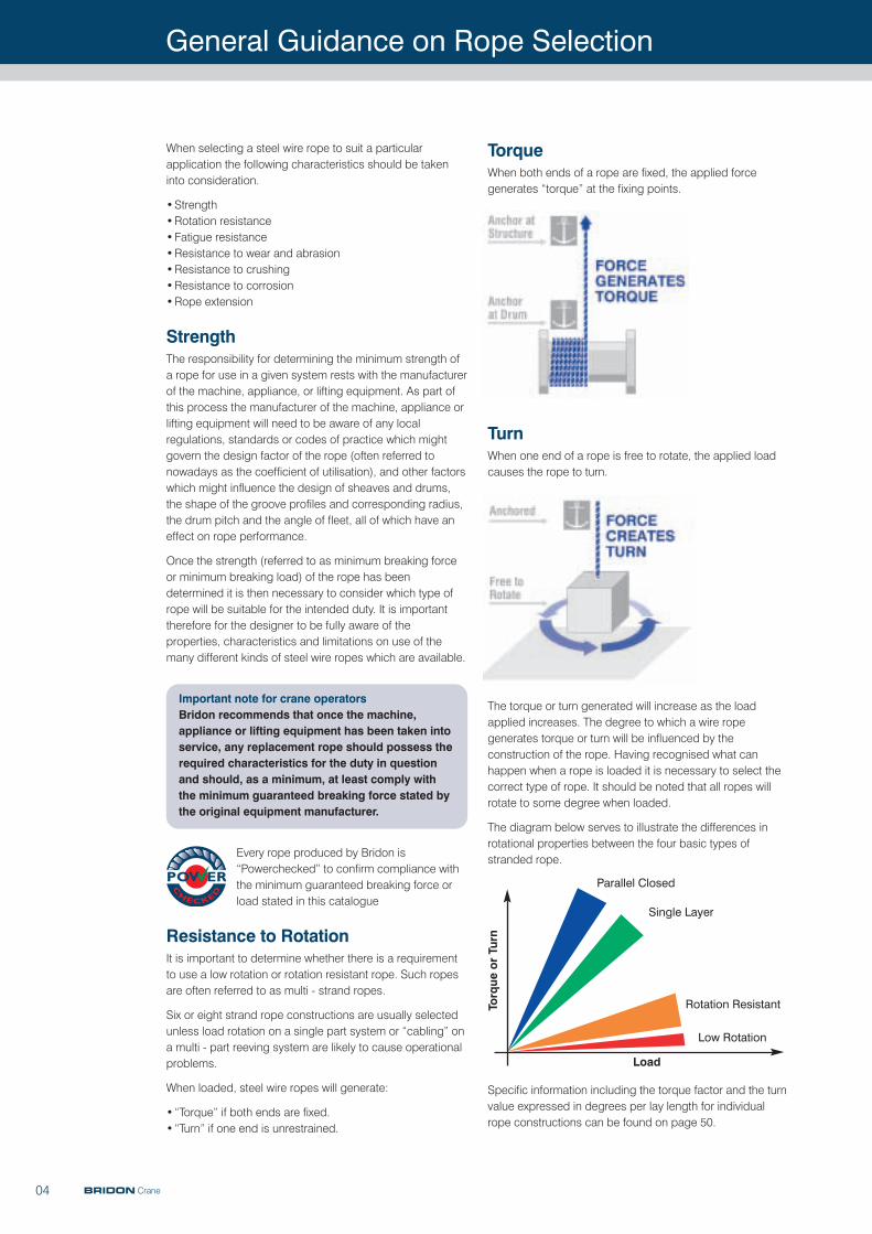
TorqueWhen both ends of a rope are fixed, the applied forcegenerates “torque” at the fixing points.
TurnWhen one end of a rope is free to rotate, the applied loadcauses the rope to turn.
The torque or turn generated will increase as the loadapplied increases. The degree to which a wire ropegenerates torque or turn will be influenced by theconstruction of the rope. Having recognised what canhappen when a rope is loaded it is necessary to select thecorrect type of rope. It should be noted that all ropes willrotate to some degree when loaded.
The diagram below serves to illustrate the differences inrotational properties between the four basic types ofstranded rope.
Specific information including the torque factor and the turnvalue expressed in degrees per lay length for individualrope constructions can be found on page 50.
When selecting a steel wire rope to suit a particularapplication the following characteristics should be takeninto consideration.
•Strength•Rotation resistance•Fatigue resistance•Resistance to wear and abrasion•Resistance to crushing•Resistance to corrosion•Rope extension
StrengthThe responsibility for determining the minimum strength ofa rope for use in a given system rests with the manufacturerof the machine, appliance, or lifting equipment. As part ofthis process the manufacturer of the machine, appliance orlifting equipment will need to be aware of any localregulations, standards or codes of practice which mightgovern the design factor of the rope (often referred tonowadays as the coefficient of utilisation), and other factorswhich might influence the design of sheaves and drums,the shape of the groove profiles and corresponding radius,the drum pitch and the angle of fleet, all of which have aneffect on rope performance.
Once the strength (referred to as minimum breaking forceor minimum breaking load) of the rope has beendetermined it is then necessary to consider which type ofrope will be suitable for the intended duty. It is importanttherefore for the designer to be fully aware of theproperties, characteristics and limitations on use of themany different kinds of steel wire ropes which are available.
Important note for crane operatorsBridon recommends that once the machine,appliance or lifting equipment has been taken intoservice, any replacement rope should possess therequired characteristics for the duty in questionand should, as a minimum, at least comply withthe minimum guaranteed breaking force stated bythe original equipment manufacturer.
Every rope produced by Bridon is“Powerchecked” to confirm compliance withthe minimum guaranteed breaking force orload stated in this catalogue
Resistance to RotationIt is important to determine whether there is a requirementto use a low rotation or rotation resistant rope. Such ropesare often referred to as multi - strand ropes.
Six or eight strand rope constructions are usually selectedunless load rotation on a single part system or “cabling” ona multi - part reeving system are likely to cause operationalproblems.
When loaded, steel wire ropes will generate:
•“Torque” if both ends are fixed.•“Turn” if one end is unrestrained.
Torque or Turn
Load
Parallel Closed
Single Layer
Rotation Resistant
Low Rotation
General Guidance on Rope Selection
05BRIDON Crane
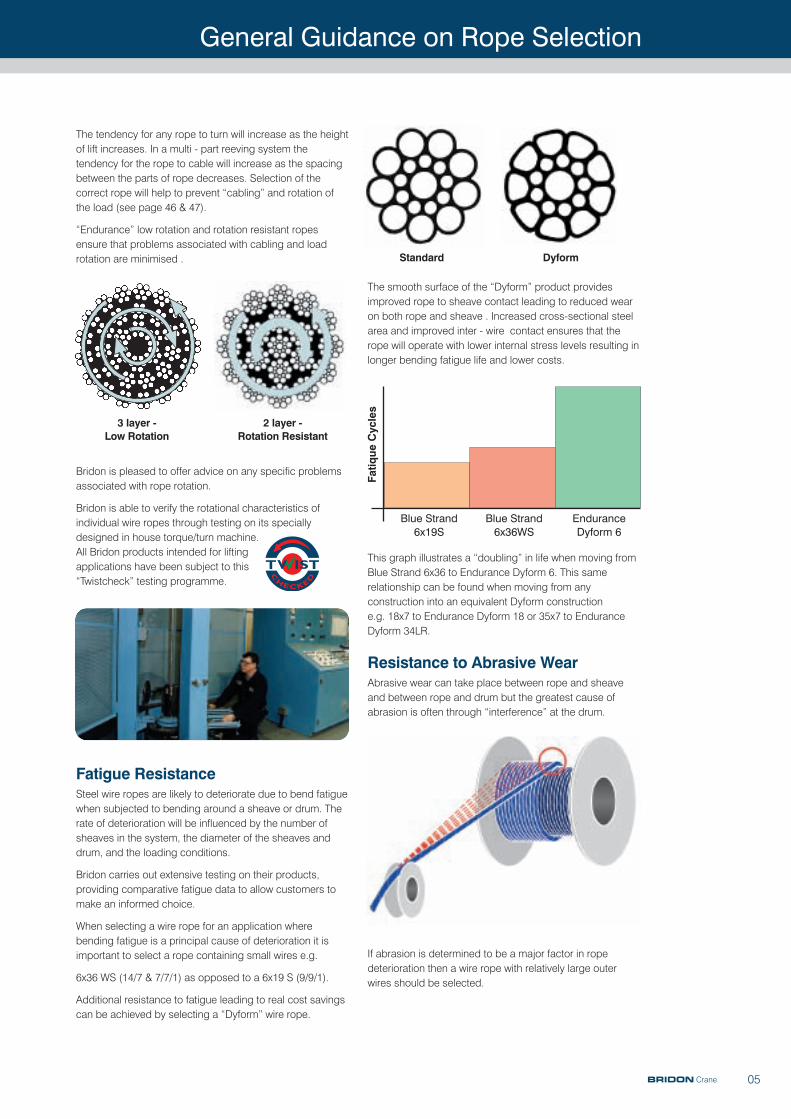
The smooth surface of the “Dyform” product providesimproved rope to sheave contact leading to reduced wearon both rope and sheave . Increased cross-sectional steelarea and improved inter - wire contact ensures that therope will operate with lower internal stress levels resulting inlonger bending fatigue life and lower costs.
This graph illustrates a “doubling” in life when moving fromBlue Strand 6x36 to Endurance Dyform 6. This samerelationship can be found when moving from anyconstruction into an equivalent Dyform construction e.g. 18x7 to Endurance Dyform 18 or 35x7 to EnduranceDyform 34LR.
Resistance to Abrasive WearAbrasive wear can take place between rope and sheaveand between rope and drum but the greatest cause ofabrasion is often through “interference” at the drum.
If abrasion is determined to be a major factor in ropedeterioration then a wire rope with relatively large outerwires should be selected.
The tendency for any rope to turn will increase as the heightof lift increases. In a multi - part reeving system thetendency for the rope to cable will increase as the spacingbetween the parts of rope decreases. Selection of thecorrect rope will help to prevent “cabling” and rotation ofthe load (see page 46 & 47).
“Endurance” low rotation and rotation resistant ropesensure that problems associated with cabling and loadrotation are minimised .
Bridon is pleased to offer advice on any specific problemsassociated with rope rotation.
Bridon is able to verify the rotational characteristics ofindividual wire ropes through testing on its speciallydesigned in house torque/turn machine. All Bridon products intended for liftingapplications have been subject to this“Twistcheck” testing programme.
Fatigue ResistanceSteel wire ropes are likely to deteriorate due to bend fatiguewhen subjected to bending around a sheave or drum. Therate of deterioration will be influenced by the number ofsheaves in the system, the diameter of the sheaves anddrum, and the loading conditions.
Bridon carries out extensive testing on their products,providing comparative fatigue data to allow customers tomake an informed choice.
When selecting a wire rope for an application wherebending fatigue is a principal cause of deterioration it isimportant to select a rope containing small wires e.g.
6x36 WS (14/7 & 7/7/1) as opposed to a 6x19 S (9/9/1).
Additional resistance to fatigue leading to real cost savingscan be achieved by selecting a “Dyform” wire rope.
3 layer - Low Rotation
2 layer - Rotation Resistant
Standard Dyform
Fatique Cycles
Blue Strand6x19S
Blue Strand6x36WS
EnduranceDyform 6
General Guidance on Rope Selection
06 BRIDON Crane
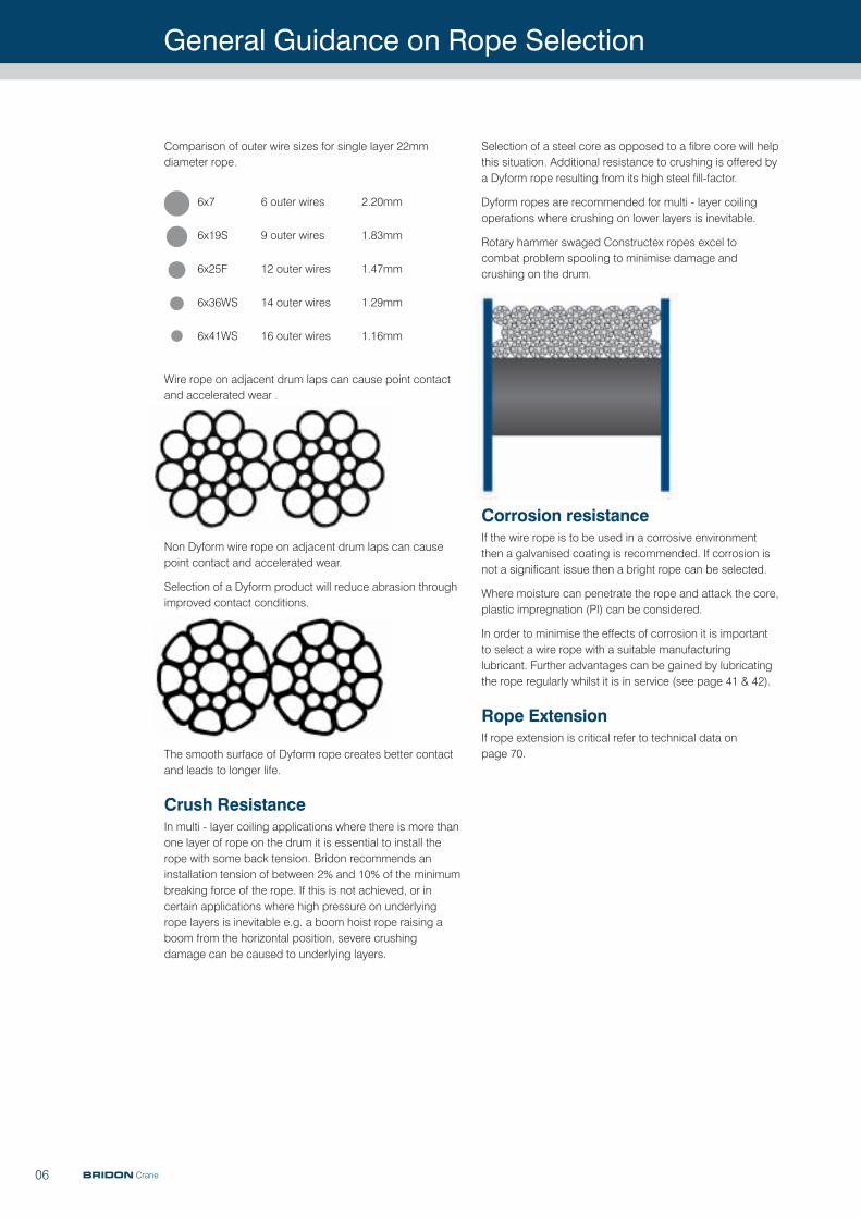
Selection of a steel core as opposed to a fibre core will helpthis situation. Additional resistance to crushing is offered bya Dyform rope resulting from its high steel fill-factor.
Dyform ropes are recommended for multi - layer coilingoperations where crushing on lower layers is inevitable.
Rotary hammer swaged Constructex ropes excel to combat problem spooling to minimise damage andcrushing on the drum.
Corrosion resistance If the wire rope is to be used in a corrosive environmentthen a galvanised coating is recommended. If corrosion isnot a significant issue then a bright rope can be selected.
Where moisture can penetrate the rope and attack the core,plastic impregnation (PI) can be considered.
In order to minimise the effects of corrosion it is importantto select a wire rope with a suitable manufacturinglubricant. Further advantages can be gained by lubricatingthe rope regularly whilst it is in service (see page 41 & 42).
Rope ExtensionIf rope extension is critical refer to technical data on page 70.
Comparison of outer wire sizes for single layer 22mmdiameter rope.
Wire rope on adjacent drum laps can cause point contactand accelerated wear .
Non Dyform wire rope on adjacent drum laps can causepoint contact and accelerated wear.
Selection of a Dyform product will reduce abrasion throughimproved contact conditions.
The smooth surface of Dyform rope creates better contactand leads to longer life.
Crush Resistance In multi - layer coiling applications where there is more thanone layer of rope on the drum it is essential to install therope with some back tension. Bridon recommends aninstallation tension of between 2% and 10% of the minimumbreaking force of the rope. If this is not achieved, or incertain applications where high pressure on underlyingrope layers is inevitable e.g. a boom hoist rope raising aboom from the horizontal position, severe crushingdamage can be caused to underlying layers.
6x7 6 outer wires 2.20mm
6x19S 9 outer wires 1.83mm
6x25F 12 outer wires 1.47mm
6x36WS 14 outer wires 1.29mm
6x41WS 16 outer wires 1.16mm
General Guidance on Rope Selection
07BRIDON Crane
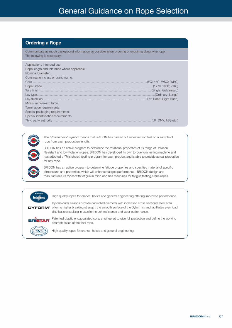
Ordering a Rope
The “Powercheck” symbol means that BRIDON has carried out a destruction test on a sample ofrope from each production length.
BRIDON has an active program to determine the rotational properties of its range of RotationResistant and low Rotation ropes. BRIDON has developed its own torque turn testing machine andhas adopted a "Twistcheck" testing program for each product and is able to provide actual propertiesfor any rope.
BRIDON has an active program to determine fatigue properties and specifies material of specificdimensions and properties, which will enhance fatigue performance. BRIDON design andmanufactures its ropes with fatigue in mind and has machines for fatigue testing crane ropes.
Dyform outer strands provide controlled diameter with increased cross sectional steel areaoffering higher breaking strength, the smooth surface of the Dyform strand facilitates even loaddistribution resulting in excellent crush resistance and wear performance.
High quality ropes for cranes, hoists and general engineering offering improved performance.
Patented plastic encapsulated core, engineered to give full protection and define the workingcharacteristics of the final rope.
High quality ropes for cranes, hoists and general engineering.
Communicate as much background information as possible when ordering or enquiring about wire rope. The following is necessary:
Application / intended use.Rope length and tolerance where applicable.Nominal Diameter.Construction, class or brand name.Core ..........................................................................................................................................(FC; FFC; WSC; IWRC)Rope Grade ....................................................................................................................................(1770; 1960; 2160)Wire finish ......................................................................................................................................(Bright; Galvanised)Lay type..............................................................................................................................................(Ordinary; Langs)Lay direction ............................................................................................................................(Left Hand; Right Hand)Minimum breaking force.Termination requirements.Special packaging requirements.Special identification requirements.Third party authority ......................................................................................................................(LR; DNV; ABS etc.)
Product Selection
08
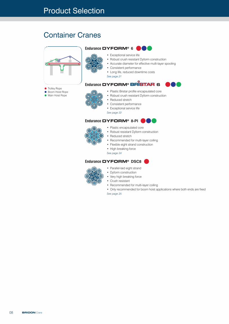
Endurance DYFORM® 6• Plastic Bristar profile encapsulated core• Robust crush resistant Dyform construction• Reduced stretch • Consistent performance • Exceptional service life See page 22
Endurance DYFORM® 8-PI
• Plastic encapsulated core• Robust resistant Dyform construction • Reduced stretch• Recommended for multi-layer coiling • Flexible eight strand construction• High breaking forceSee page 24
Endurance DYFORM® DSC8
• Parallel-laid eight strand• Dyform construction • Very high breaking force• Crush resistant • Recommended for multi-layer coiling • Only recommended for boom hoist applications where both ends are fixedSee page 25
Container Cranes
Endurance DYFORM® 6
• Exceptional service life• Robust crush resistant Dyform construction• Accurate diameter for effective multi-layer spooling • Consistent performance • Long life, reduced downtime costs See page 21
•Trolley Rope
•Boom Hoist Rope
•Main Hoist Rope
BRIDON Crane
Product Selection
09
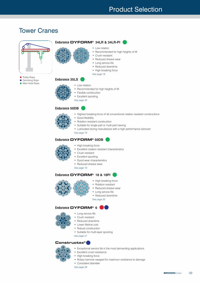
Tower Cranes
Endurance DYFORM® 34LR & 34LR-PI
• Low rotation• Recommended for high heights of lift• Crush resistant • Reduced sheave wear• Long service life• Reduced downtime• High breaking forceSee page 18
Endurance 35LS
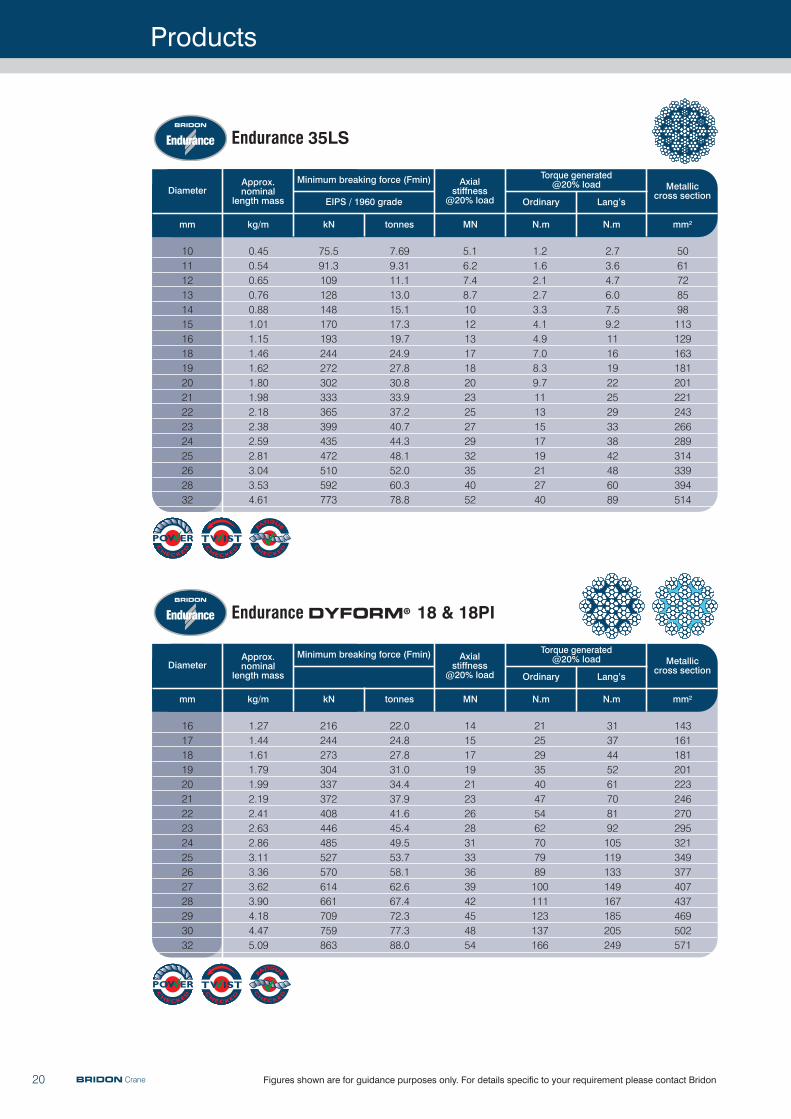
• Low rotation• Recommended for high heights of lift• Flexible construction• Excellent spoolingSee page 20
Endurance 50DB
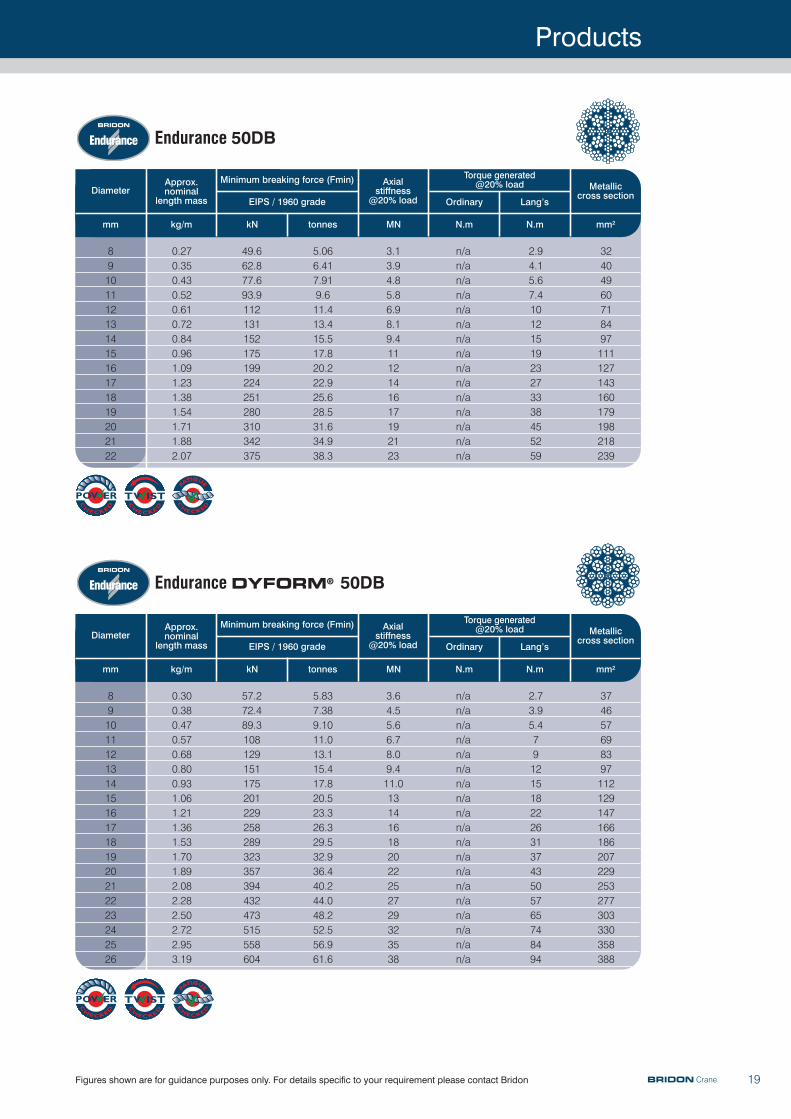
• Highest breaking force of all conventional rotation resistant constructions• Good flexibility• Rotation resistant construction• Suitable for single part or multi-part reeving• Lubricated during manufacture with a high performance lubricantSee page 19
Endurance DYFORM® 6
• Long service life• Crush resistant • Reduced downtime• Lower lifetime cost• Robust construction• Suitable for multi-layer spooling See page 21
Endurance DYFORM® 18 & 18PI
• High breaking force • Rotation resistant• Reduced sheave wear• Long service life• Reduced downtimeSee page 20
Endurance DYFORM® 50DB
• High breaking force• Excellent rotation resistant characteristics• Crush resistant• Excellent spooling• Good wear characteristics• Reduced sheave wearSee page 19
•Trolley Rope
•Derricking Rope
•Main Hoist Rope
BRIDON Crane
Constructex®
• Exceptional service life in the most demanding applications• Excellent crush resistance• High breaking force• Rotary hammer swaged for maximum resistance to damage• Consistent diameterSee page 28

Product Selection
10 BRIDON Crane
Endurance 35LS
• Low rotation • Good flexibility • Recommended for high heights of lift• Suitable for single-part and multi-part reeving See page 20
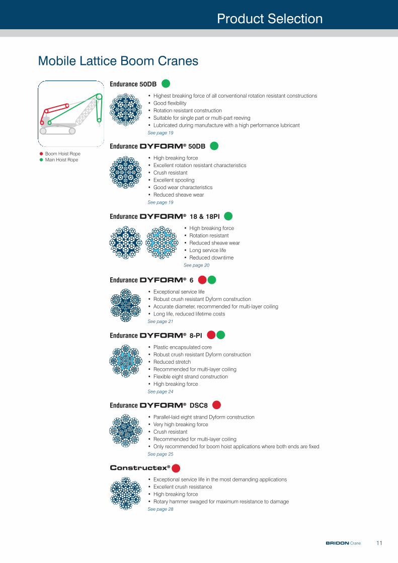
Mobile Lattice Boom Cranes
Endurance DYFORM® 34LR & 34LR-PI
• Low rotation Dyform• Recommended for high lifting operations• High strength• Reduced rope sheave wear• Accurate diameter, recommended for multi-layer coiling• Suitable for single part and multi-part reeving• Long service lifeSee page 18
•Boom Hoist Rope
•Main Hoist Rope
Endurance 35LS
• Low rotation• Recommended for high heights of lift• Good flexibility• Suitable for single-part and multi-part reevingSee page 20
Endurance 50DB
• Highest breaking force of all conventional rotation resistant constructions• Good flexibility• Rotation resistant construction• Suitable for single part or multi-part reeving• Lubricated during manufacture with a high performance lubricantSee page 19
Telescopic Mobile Cranes
Endurance DYFORM® 34LR & 34LR-PI
• Low rotation• Long service life• Crush resistant• Recommended for multi-layer coiling• Recommended for high heights of lift• Suitable for single-part and multi-part reevingSee page 18
•Main Hoist Rope
Endurance DYFORM® 18 & 18PI
• High breaking force • Rotation resistant• Reduced sheave wear• Long service life• Reduced downtimeSee page 20
Endurance DYFORM® 50DB
• High breaking force• Excellent rotation resistant characteristics• Crush resistant• Excellent spooling• Good wear characteristics• Reduced sheave wearSee page 19
Product Selection
11BRIDON Crane
Endurance 50DB
• Highest breaking force of all conventional rotation resistant constructions• Good flexibility• Rotation resistant construction• Suitable for single part or multi-part reeving• Lubricated during manufacture with a high performance lubricantSee page 19
Endurance DYFORM® 6
• Exceptional service life• Robust crush resistant Dyform construction• Accurate diameter, recommended for multi-layer coiling• Long life, reduced lifetime costsSee page 21
Endurance DYFORM® 8-PI
• Plastic encapsulated core• Robust crush resistant Dyform construction• Reduced stretch• Recommended for multi-layer coiling• Flexible eight strand construction• High breaking forceSee page 24
Endurance DYFORM® DSC8
• Parallel-laid eight strand Dyform construction• Very high breaking force • Crush resistant• Recommended for multi-layer coiling • Only recommended for boom hoist applications where both ends are fixedSee page 25
Constructex®
• Exceptional service life in the most demanding applications • Excellent crush resistance • High breaking force• Rotary hammer swaged for maximum resistance to damageSee page 28
Mobile Lattice Boom Cranes
•Boom Hoist Rope
•Main Hoist Rope
Endurance DYFORM® 18 & 18PI
• High breaking force • Rotation resistant• Reduced sheave wear• Long service life• Reduced downtimeSee page 20
Endurance DYFORM® 50DB
• High breaking force• Excellent rotation resistant characteristics• Crush resistant• Excellent spooling• Good wear characteristics• Reduced sheave wearSee page 19
Product Selection
12 BRIDON Crane
Endurance DYFORM® 8-PI
• Plastic encapsulated core • Robust crush resistant Dyform construction • Reduced stretch • Flexible eight strand construction • High breaking force See page 24
Endurance DYFORM® 6• Plastic Bristar profile encapsulated core• Robust crush resistant Dyform construction• Reduced stretch • Exceptional service lifeSee page 22
• Plastic encapsulated core incorporating plastic sections between outer strands• Robust crush resistant Dyform construction• Exceptional fatigue properties• Reduced stretch• Reduced lifetime costs See page 22
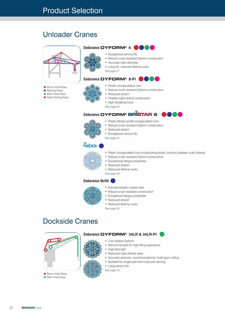
Unloader Cranes
Endurance DYFORM® 6
• Exceptional service life• Robust crush resistant Dyform construction • Accurate rope diameter • Long life, reduced lifetime costsSee page 21
•Boom Hoist Rope
•Racking Rope
•Main Hoist Rope
•Grab Closing Rope
Endurance Brifil
• Extruded plastic coated rope• Robust crush resistant construction• Exceptional fatigue properties• Reduced stretch• Reduced lifetime costsSee page 23
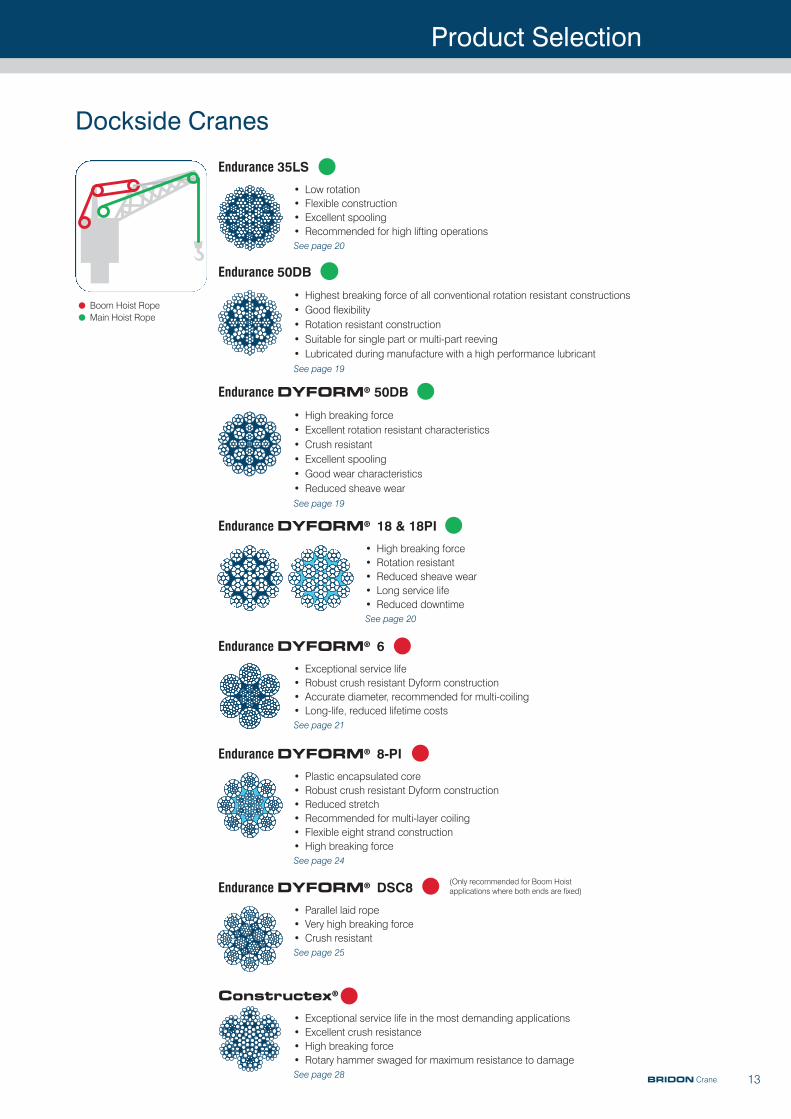
Dockside Cranes
Endurance DYFORM® 34LR & 34LR-PI
• Low rotation Dyform• Recommended for high lifting operations• High Strength• Reduced rope sheave wear• Accurate diameter, recommended for multi-layer coiling • Suitable for single part and multi-part reeving • Long service lifeSee page 18
•Boom Hoist Rope
•Main Hoist Rope
Product Selection
13BRIDON Crane
Endurance 35LS
• Low rotation• Flexible construction• Excellent spooling • Recommended for high lifting operationsSee page 20
Endurance 50DB
• Highest breaking force of all conventional rotation resistant constructions• Good flexibility• Rotation resistant construction• Suitable for single part or multi-part reeving• Lubricated during manufacture with a high performance lubricantSee page 19
Endurance DYFORM® 6
• Exceptional service life• Robust crush resistant Dyform construction • Accurate diameter, recommended for multi-coiling • Long-life, reduced lifetime costs See page 21
Endurance DYFORM® 8-PI
• Plastic encapsulated core • Robust crush resistant Dyform construction• Reduced stretch • Recommended for multi-layer coiling • Flexible eight strand construction• High breaking forceSee page 24
Constructex®
• Exceptional service life in the most demanding applications• Excellent crush resistance• High breaking force• Rotary hammer swaged for maximum resistance to damage See page 28
Dockside Cranes
•Boom Hoist Rope
•Main Hoist Rope
Endurance DYFORM® DSC8
• Parallel laid rope• Very high breaking force• Crush resistant See page 25
(Only recommended for Boom Hoistapplications where both ends are fixed)
Endurance DYFORM® 18 & 18PI
• High breaking force • Rotation resistant• Reduced sheave wear• Long service life• Reduced downtimeSee page 20
Endurance DYFORM® 50DB
• High breaking force• Excellent rotation resistant characteristics• Crush resistant• Excellent spooling• Good wear characteristics• Reduced sheave wearSee page 19
Product Selection
14
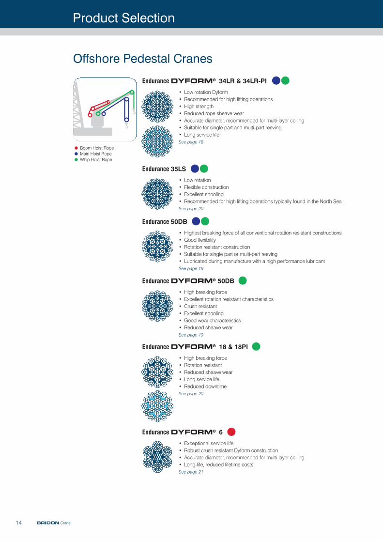
Endurance 35LS
• Low rotation • Flexible construction • Excellent spooling • Recommended for high lifting operations typically found in the North SeaSee page 20
Endurance 50DB
• Highest breaking force of all conventional rotation resistant constructions• Good flexibility• Rotation resistant construction• Suitable for single part or multi-part reeving• Lubricated during manufacture with a high performance lubricantSee page 19
Endurance DYFORM® 6
• Exceptional service life• Robust crush resistant Dyform construction• Accurate diameter, recommended for multi-layer coiling • Long-life, reduced lifetime costs See page 21
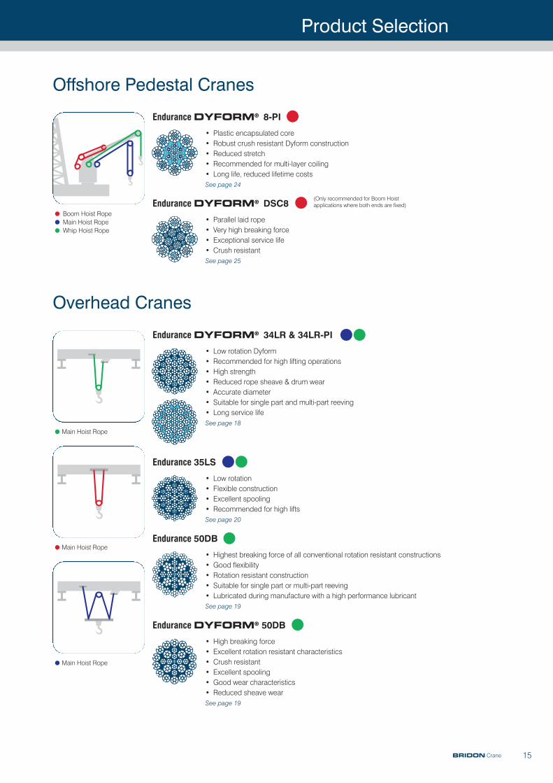
Offshore Pedestal Cranes
Endurance DYFORM® 34LR & 34LR-PI
• Low rotation Dyform• Recommended for high lifting operations• High strength• Reduced rope sheave wear• Accurate diameter, recommended for multi-layer coiling • Suitable for single part and multi-part reeving • Long service life See page 18
•Boom Hoist Rope
•Main Hoist Rope
•Whip Hoist Rope
Endurance DYFORM® 18 & 18PI
• High breaking force • Rotation resistant• Reduced sheave wear• Long service life• Reduced downtimeSee page 20
BRIDON Crane
Endurance DYFORM® 50DB
• High breaking force• Excellent rotation resistant characteristics• Crush resistant• Excellent spooling• Good wear characteristics• Reduced sheave wearSee page 19
Product Selection
15
Endurance DYFORM® 8-PI
• Plastic encapsulated core• Robust crush resistant Dyform construction• Reduced stretch• Recommended for multi-layer coiling • Long life, reduced lifetime costsSee page 24
Endurance DYFORM® DSC8
• Parallel laid rope • Very high breaking force• Exceptional service life• Crush resistant See page 25
Offshore Pedestal Cranes
•Boom Hoist Rope
•Main Hoist Rope
•Whip Hoist Rope
(Only recommended for Boom Hoistapplications where both ends are fixed)
BRIDON Crane
Endurance 35LS
• Low rotation• Flexible construction• Excellent spooling • Recommended for high lifts See page 20
Endurance 50DB
• Highest breaking force of all conventional rotation resistant constructions• Good flexibility• Rotation resistant construction• Suitable for single part or multi-part reeving• Lubricated during manufacture with a high performance lubricantSee page 19
Overhead Cranes
Endurance DYFORM® 34LR & 34LR-PI
• Low rotation Dyform• Recommended for high lifting operations• High strength• Reduced rope sheave & drum wear• Accurate diameter • Suitable for single part and multi-part reeving • Long service lifeSee page 18
•Main Hoist Rope
•Main Hoist Rope
•Main Hoist Rope
Endurance DYFORM® 50DB
• High breaking force• Excellent rotation resistant characteristics• Crush resistant• Excellent spooling• Good wear characteristics• Reduced sheave wearSee page 19
Product Selection
16
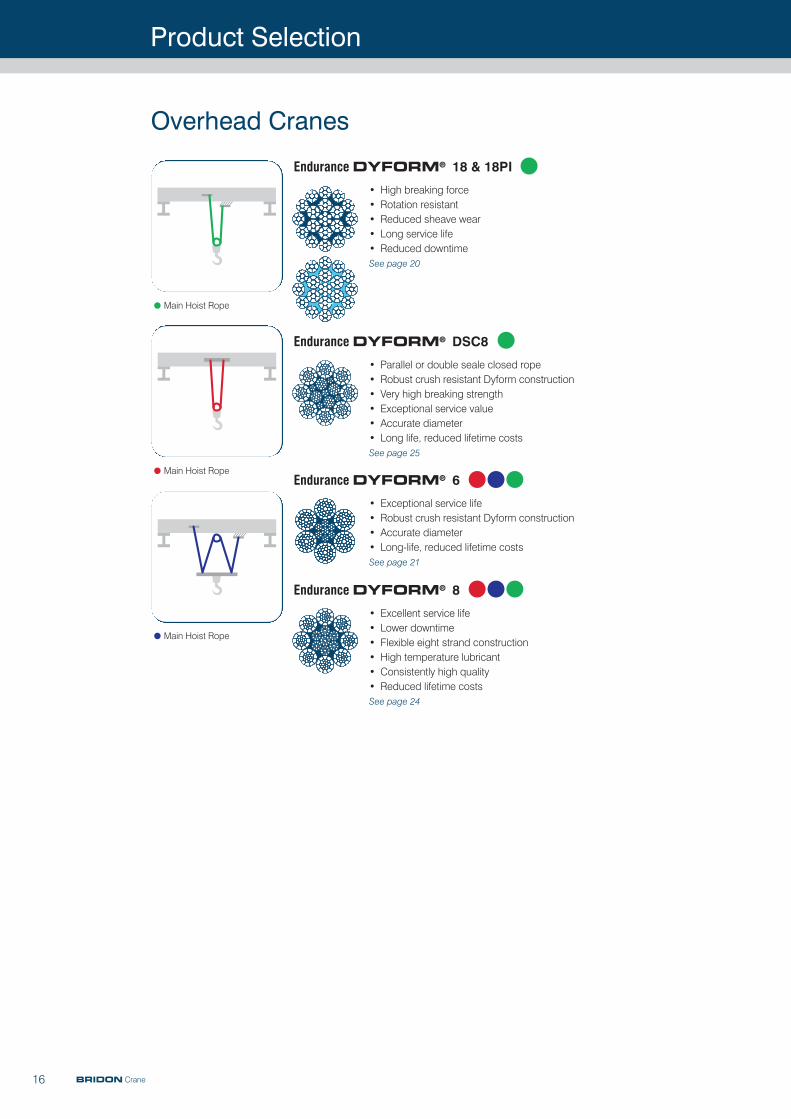
Endurance DYFORM® DSC8
• Parallel or double seale closed rope • Robust crush resistant Dyform construction• Very high breaking strength • Exceptional service value• Accurate diameter • Long life, reduced lifetime costsSee page 25
Endurance DYFORM® 6
• Exceptional service life• Robust crush resistant Dyform construction • Accurate diameter• Long-life, reduced lifetime costsSee page 21
Endurance DYFORM® 8
• Excellent service life • Lower downtime• Flexible eight strand construction• High temperature lubricant• Consistently high quality • Reduced lifetime costs See page 24
Overhead Cranes
•Main Hoist Rope
•Main Hoist Rope
•Main Hoist Rope
BRIDON Crane
Endurance DYFORM® 18 & 18PI
• High breaking force • Rotation resistant• Reduced sheave wear• Long service life• Reduced downtimeSee page 20
Product Selection
17
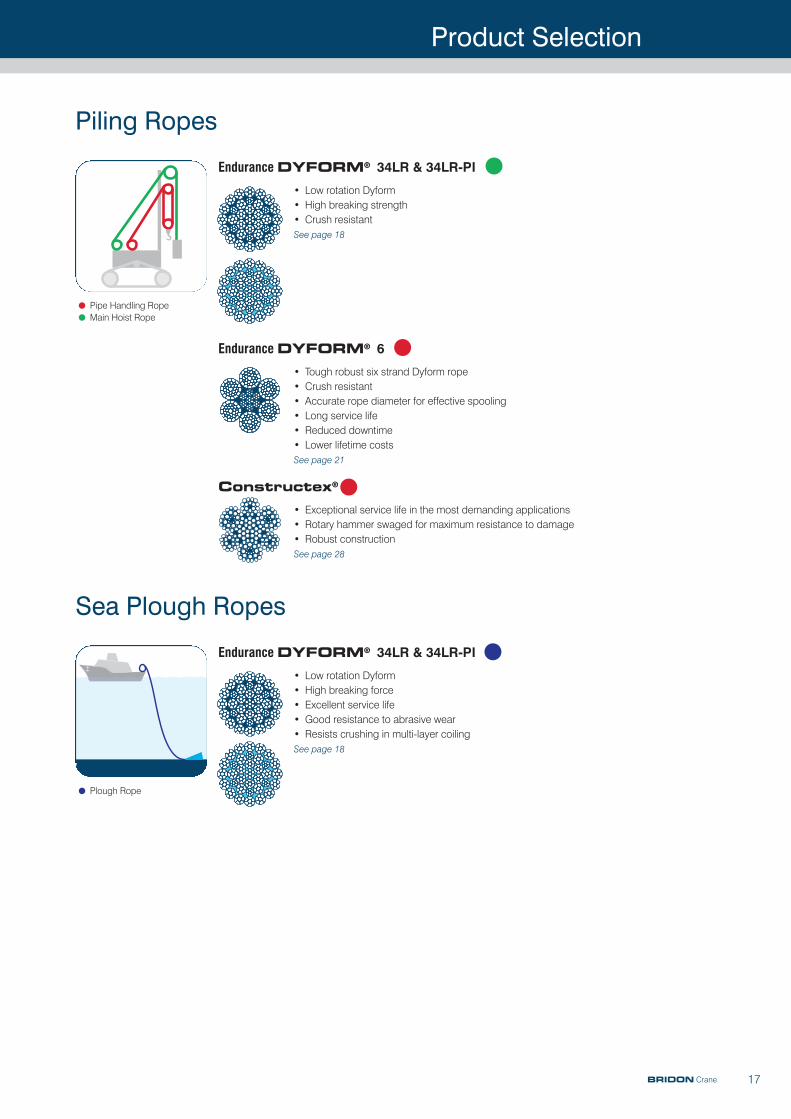
Endurance DYFORM® 6
• Tough robust six strand Dyform rope• Crush resistant • Accurate rope diameter for effective spooling • Long service life• Reduced downtime• Lower lifetime costsSee page 21
Constructex®
• Exceptional service life in the most demanding applications• Rotary hammer swaged for maximum resistance to damage• Robust construction See page 28
Piling Ropes
Endurance DYFORM® 34LR & 34LR-PI
• Low rotation Dyform• High breaking strength• Crush resistantSee page 18
Sea Plough Ropes
Endurance DYFORM® 34LR & 34LR-PI
• Low rotation Dyform• High breaking force• Excellent service life• Good resistance to abrasive wear• Resists crushing in multi-layer coilingSee page 18
•Pipe Handling Rope
•Main Hoist Rope
•Plough Rope
BRIDON Crane
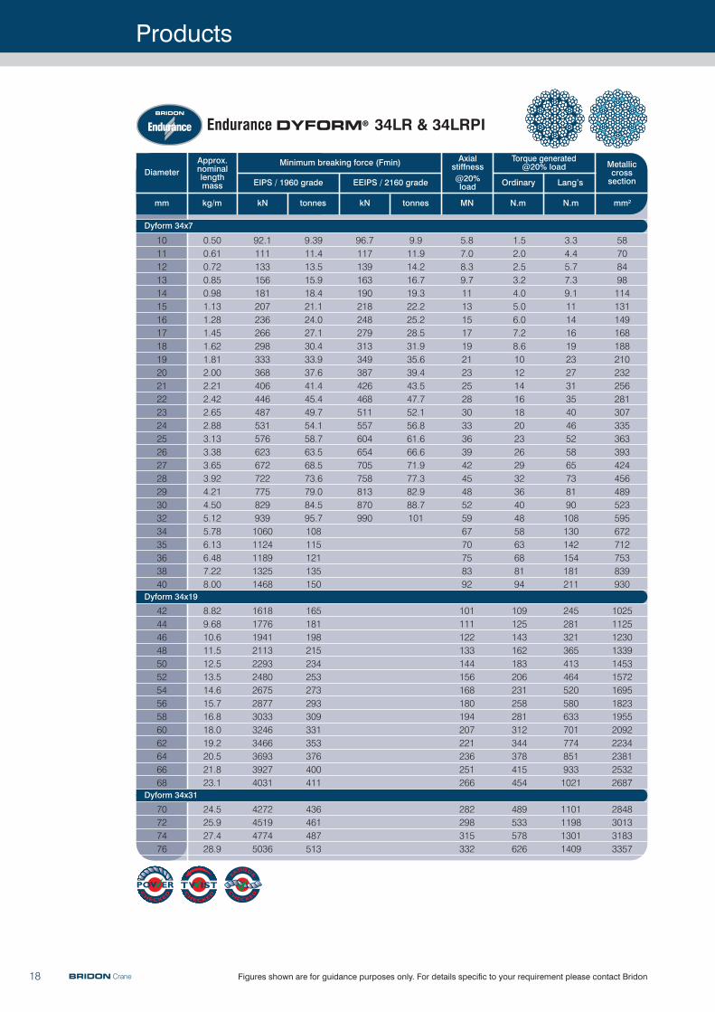
Diameter
mm
EIPS / 1960 grade
Minimum breaking force (Fmin)
EEIPS / 2160 grade @20% load
Axialstiffness
Torque generated @20% load Metallic
crosssectionLang’sOrdinary
mm2kg/m kN tonnes kN tonnes MN N.mN.m
Approx.nominal lengthmass
101112131415161718192021222324252627282930323435363840
4244464850525456586062646668
70727476
0.500.610.720.850.981.131.281.451.621.812.002.212.422.652.883.133.383.653.924.214.505.125.786.136.487.228.00
8.829.6810.611.512.513.514.615.716.818.019.220.521.823.1
24.525.927.428.9
Products
18
92.111113315618120723626629833336840644648753157662367272277582993910601124118913251468
16181776194121132293248026752877303332463466369339274031
4272451947745036
9.3911.413.515.918.421.124.027.130.433.937.641.445.449.754.158.763.568.573.679.084.595.7108115121135150
165181198215234253273293309331353376400411
436461487513
96.7117139163190218248279313349387426468511557604654705758813870990
9.911.914.216.719.322.225.228.531.935.639.443.547.752.156.861.666.671.977.382.988.7101
5.87.08.39.71113151719212325283033363942454852596770758392
101111122133144156168180194207221236251266
282298315332
1.52.02.53.24.05.06.07.28.6101214161820232629323640485863688194
109125143162183206231258281312344378415454
489533578626
3.34.45.77.39.111141619232731354046525865738190108130142154181211
2452813213654134645205806337017748519331021
1101119813011409
58708498114131149168188210232256281307335363393424456489523595672712753839930
10251125123013391453157216951823195520922234238125322687
2848301331833357
Figures shown are for guidance purposes only. For details specific to your requirement please contact Bridon
Dyform 34x7
Dyform 34x19
Dyform 34x31
Endurance DYFORM® 34LR & 34LRPI
BRIDON Crane
Products
19Figures shown are for guidance purposes only. For details specific to your requirement please contact Bridon
Diameter
mm
EIPS / 1960 grade
Minimum breaking force (Fmin) Axial stiffness
@20% load
Torque generated @20% load Metallic
cross section
mm2kg/m kN tonnes MN N.mN.m
Lang’sOrdinary
Approx.nominal
length mass
8910111213141516171819202122
0.270.350.430.520.610.720.840.961.091.231.381.541.711.882.07
49.662.877.693.9112131152175199224251280310342375
5.066.417.919.611.413.415.517.820.222.925.628.531.634.938.3
3.13.94.85.86.98.19.41112141617192123
2.94.15.67.41012151923273338455259
n/an/an/an/an/an/an/an/an/an/an/an/an/an/an/a
32404960718497111127143160179198218239
Endurance 50DB
BRIDON Crane
Diameter
mm
EIPS / 1960 grade
Minimum breaking force (Fmin) Axial stiffness
@20% load
Torque generated @20% load Metallic
cross section
mm2kg/m kN tonnes MN N.mN.m
Lang’sOrdinary
Approx.nominal
length mass
891011121314151617181920212223242526
0.300.380.470.570.680.800.931.061.211.361.531.701.892.082.282.502.722.953.19
57.272.489.3108129151175201229258289323357394432473515558604
5.837.389.1011.013.115.417.820.523.326.329.532.936.440.244.048.252.556.961.6
3.64.55.66.78.09.411.0131416182022252729323538
2.73.95.4791215182226313743505765748494
n/an/an/an/an/an/an/an/an/an/an/an/an/an/an/an/an/an/an/a
374657698397112129147166186207229253277303330358388
Endurance DYFORM® 50DB
Products
20 Figures shown are for guidance purposes only. For details specific to your requirement please contact BridonBRIDON Crane
Diameter
mm
Minimum breaking force (Fmin) Axial stiffness
@20% load
Torque generated @20% load Metallic
cross section
mm2kg/m kN tonnes MN N.mN.m
Lang’sOrdinary
Approx.nominal
length mass
16171819202122232425262728293032
1.271.441.611.791.992.192.412.632.863.113.363.623.904.184.475.09
216244273304337372408446485527570614661709759863
22.024.827.831.034.437.941.645.449.553.758.162.667.472.377.388.0
14151719212326283133363942454854
3137445261708192105119133149167185205249
2125293540475462707989100111123137166
143161181201223246270295321349377407437469502571
Endurance DYFORM® 18 & 18PI
Diameter
mm
EIPS / 1960 grade
Minimum breaking force (Fmin) Axial stiffness
@20% load
Torque generated @20% load Metallic
cross section
mm2kg/m kN tonnes MN N.mN.m
Lang’sOrdinary
Approx.nominal
length mass
101112131415161819202122232425262832
0.450.540.650.760.881.011.151.461.621.801.982.182.382.592.813.043.534.61
75.591.3109128148170193244272302333365399435472510592773
7.699.3111.113.015.117.319.724.927.830.833.937.240.744.348.152.060.378.8
5.16.27.48.71012131718202325272932354052
2.73.64.76.07.59.2111619222529333842486089
1.21.62.12.73.34.14.97.08.39.71113151719212740
5061728598113129163181201221243266289314339394514
Endurance 35LS
Products
21
Diameter
mm
EIPS / 1960 grade
Minimum breaking force (Fmin)
EEIPS / 2160 grade
Axialstiffness@20% load
Torque generated@20% load Metallic
crosssectionLang’sOrdinary
mm2kg/m kN tonnes kN tonnes MN N.mN.m
Approx.nominal lengthmass
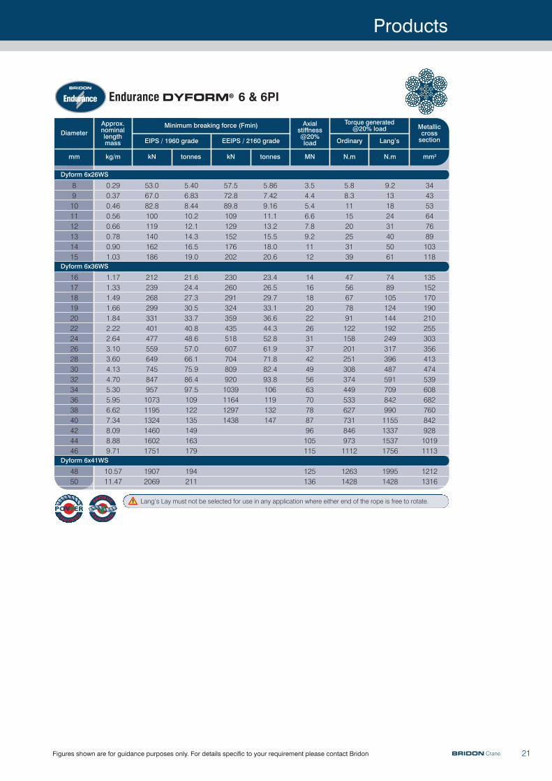
89101112131415
161718192022242628303234363840424446
4850
0.290.370.460.560.660.780.901.03
1.171.331.491.661.842.222.643.103.604.134.705.305.956.627.348.098.889.71
10.5711.47
53.067.082.8100119140162186
212239268299331401477559649745847957107311951324146016021751
19072069
5.406.838.4410.212.114.316.519.0
21.624.427.330.533.740.848.657.066.175.986.497.5109122135149163179
194211
57.572.889.8109129152176202
2302602913243594355186077048099201039116412971438
5.867.429.1611.113.215.518.020.6
23.426.529.733.136.644.352.861.971.882.493.8106119132147
3.54.45.46.67.89.21112
14161820222631374249566370788796105115
125136
5.88.3111520253139
47566778911221582012513083744495336277318469731112
12631428
9.213182431405061
74891051241441922493173964875917098429901155133715371756
19951428
344353647689103118
13515217019021025530335641347453960868276084292810191113
12121316
Figures shown are for guidance purposes only. For details specific to your requirement please contact Bridon
Lang’s Lay must not be selected for use in any application where either end of the rope is free to rotate.
Dyform 6x26WS
Dyform 6x36WS
Dyform 6x41WS
Endurance DYFORM® 6 & 6PI
BRIDON Crane
Products
22 Figures shown are for guidance purposes only. For details specific to your requirement please contact Bridon
Diameter
mm
EIPS / 1960 grade
Minimum breaking force (Fmin)
EEIPS / 2160 grade
Axialstiffness@20% load
Torque generated@20% load Metallic
crosssectionLang’sOrdinary
mm2kg/m kN tonnes kN tonnes MN N.mN.m
Approx.nominal lengthmass
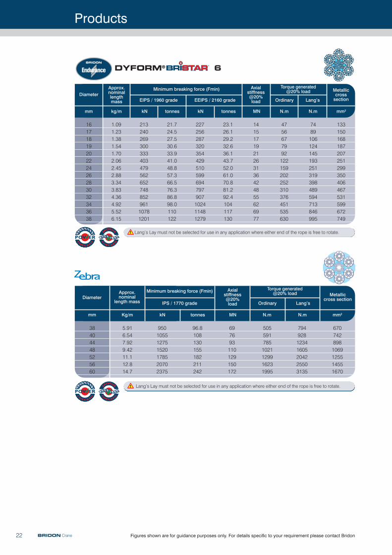
1617181920222426283032343638
1.091.231.381.541.702.062.452.883.343.834.364.925.526.15
DYFORM® 6
21324026930033340347956265274885296110781201
21.724.527.530.633.941.048.857.366.576.386.898.0110122
227256287320354429510599694797907102411481279
23.126.129.232.636.143.752.061.070.881.292.4104117130
1415171921263136424855626977
4756677992122159202252310376451535630
7489106124145193251319398489594713846995
133150168187207251299350406467531599672749
Lang’s Lay must not be selected for use in any application where either end of the rope is free to rotate.
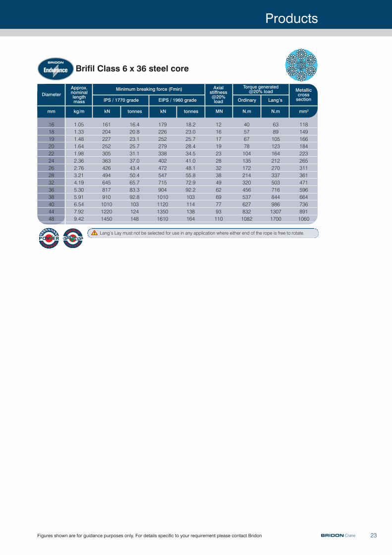
Diameter
kN tonnes MN N.m N.m mm2Kg/mmm
Approx.nominal
length mass
Axial stiffness@20% load
Metalliccross section
Minimum breaking force (Fmin)
IPS / 1770 grade
Torque generated@20% load
Ordinary Lang’s
38404448525660
5.916.547.929.4211.112.814.7
950105512751520178520702375
96.8108130155182211242
697693110129150172
5055917851021129916231995
79492812341605204225503135
6707428981069125514551670
BRIDON Crane
Lang’s Lay must not be selected for use in any application where either end of the rope is free to rotate.
Products
23Figures shown are for guidance purposes only. For details specific to your requirement please contact Bridon BRIDON Crane
Diameter
mm
IPS / 1770 grade
Minimum breaking force (Fmin)
EIPS / 1960 grade
Axialstiffness@20% load
Torque generated@20% load Metallic
crosssectionLang’sOrdinary
mm2kg/m kN tonnes kN tonnes MN N.mN.m
Approx.nominal lengthmass
1618192022242628323638404448
1.051.331.481.641.982.362.763.214.195.305.916.547.929.42
Brifil Class 6 x 36 steel core
161204227252305363426494645817910101012201450
16.420.823.125.731.137.043.450.465.783.392.8103124148
1792262522793384024725477159041010112013501610
18.223.025.728.434.541.048.155.872.992.2103114138164
12161719232832384962697793110
405767781041351722143204565376278321082
638910512316421227033750371684498613071700
1181491661842232653113614715966647368911060
Lang’s Lay must not be selected for use in any application where either end of the rope is free to rotate.
Products
24 Figures shown are for guidance purposes only. For details specific to your requirement please contact Bridon
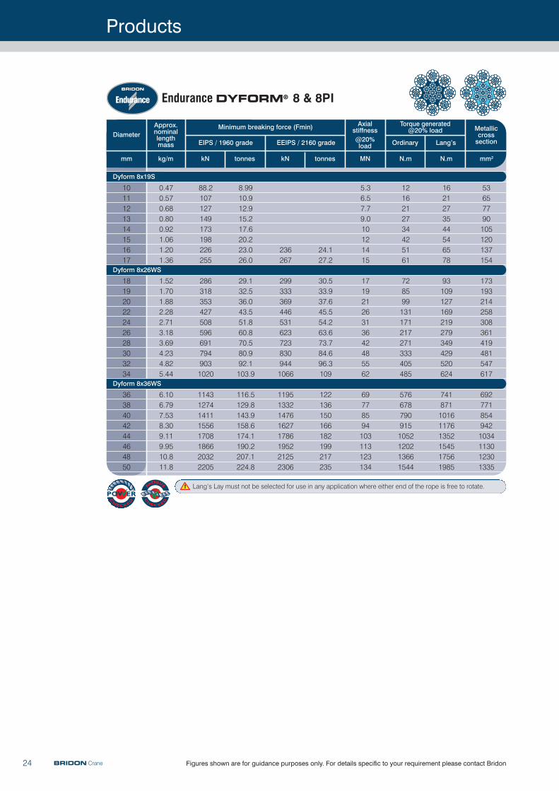
Diameter
mm
EIPS / 1960 grade
Minimum breaking force (Fmin)
EEIPS / 2160 grade @20% load
Axialstiffness
Torque generated@20% load Metallic
crosssectionLang’s
mm2kg/m kN tonnes kN tonnes MN N.m
Ordinary
N.m
Approx.nominal lengthmass
1011121314151617
18192022242628303234
3638404244464850
0.470.570.680.800.921.061.201.36
1.521.701.882.282.713.183.694.234.825.44
6.106.797.538.309.119.9510.811.8
88.2107127149173198226255
2863183534275085966917949031020
11431274141115561708186620322205
8.9910.912.915.217.620.223.026.0
29.132.536.043.551.860.870.580.992.1103.9
116.5129.8143.9158.6174.1190.2207.1224.8
236267
2993333694465316237238309441066
11951332147616271786195221252306
24.127.2
30.533.937.645.554.263.673.784.696.3109
122136150166182199217235
5.36.57.79.010121415
17192126313642485562
69778594103113123134
1216212734425161
728599131171217271333405485
5766787909151052120213661544
1621273544546578
93109127169219279349429520624
741871101611761352154517561985
53657790105120137154
173193214258308361419481547617
6927718549421034113012301335
Lang’s Lay must not be selected for use in any application where either end of the rope is free to rotate.
Dyform 8x19S
Dyform 8x26WS
Dyform 8x36WS
Endurance DYFORM® 8 & 8PI
BRIDON Crane
Products
25Figures shown are for guidance purposes only. For details specific to your requirement please contact Bridon
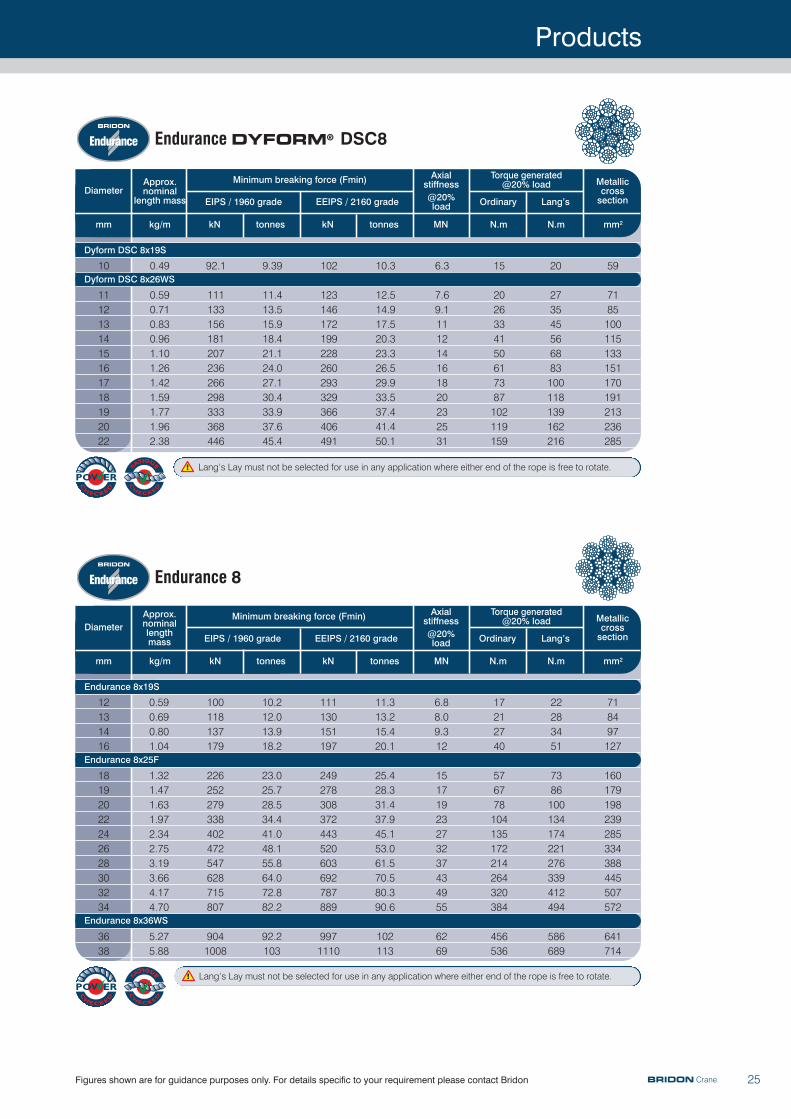
Diameter
mm
EIPS / 1960 grade
Minimum breaking force (Fmin)
EEIPS / 2160 grade @20% load
Axialstiffness
Torque generated@20% load Metallic
crosssectionLang’sOrdinary
mm2kg/m kN tonnes kN tonnes MN N.mN.m
Approx.nominal
length mass
10
1112131415161718192022
0.49
0.590.710.830.961.101.261.421.591.771.962.38
92.1
111133156181207236266298333368446
9.39
11.413.515.918.421.124.027.130.433.937.645.4
102
123146172199228260293329366406491
10.3
12.514.917.520.323.326.529.933.537.441.450.1
6.3
7.69.1111214161820232531
15
2026334150617387102119159
20
273545566883100118139162216
59
7185100115133151170191213236285
Lang’s Lay must not be selected for use in any application where either end of the rope is free to rotate.
Diameter
mm
EIPS / 1960 grade
Minimum breaking force (Fmin)
EEIPS / 2160 grade @20% load
Axialstiffness
Torque generated@20% load Metallic
crosssectionLang’s
mm2kg/m kN tonnes kN tonnes MN N.m
Ordinary
N.m
Approx.nominal lengthmass
12131416
18192022242628303234
3638
0.590.690.801.04
1.321.471.631.972.342.753.193.664.174.70
5.275.88
100118137179
226252279338402472547628715807
9041008
10.212.013.918.2
23.025.728.534.441.048.155.864.072.882.2
92.2103
111130151197
249278308372443520603692787889
9971110
11.313.215.420.1
25.428.331.437.945.153.061.570.580.390.6
102113
6.88.09.312
15171923273237434955
6269
17212740
576778104135172214264320384
456536
22283451
7386100134174221276339412494
586689
718497127
160179198239285334388445507572
641714
Lang’s Lay must not be selected for use in any application where either end of the rope is free to rotate.
Dyform DSC 8x19S
Dyform DSC 8x26WS
Endurance 8x19S
Endurance 8x25F
Endurance 8x36WS
Endurance DYFORM® DSC8
Endurance 8
BRIDON Crane
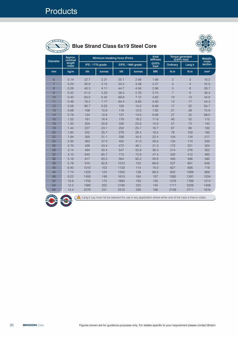
Diameter
mm
IPS / 1770 grade
Minimum breaking force (Fmin)
EIPS / 1960 grade @20% load
Axialstiffness
Torque generated@20% load Metallic
crosssectionLang’s
mm2kg/m kN tonnes kN tonnes MN N.m
Ordinary
N.m
Approx.nominal lengthmass
678910111213141618192022242628323638404448525660
0.140.200.260.320.400.480.580.680.781.021.301.441.601.942.302.703.144.105.185.786.407.749.2210.812.514.4
22.730.940.351.063.076.290.7106124161204227252305363426494645817910101012201450170019802270
2.313.154.115.206.427.779.2510.812.616.420.823.125.731.137.043.450.465.783.392.8103124148173202231
25.134.244.756.569.884.41001181371792262522793384024725477159041010112013501610189021902510
2.563.494.565.767.128.6010.212.014.018.223.025.728.434.541.048.155.872.992.2103114138164193223256
1.662.272.963.754.625.606.667.829.0611.815.016.718.522.426.631.336.347.459.966.874.089.5107125145166
23571013172127405767781041351722143204565376278321082137617172108
3469131722283552738610013417422127641258669180610691391176922082711
16.222.028.736.444.954.364.775.988.01151451621802172593043524605826487188691034121414081616
Blue Strand Class 6x19 Steel Core
Lang’s Lay must not be selected for use in any application where either end of the rope is free to rotate.
Products
26 Figures shown are for guidance purposes only. For details specific to your requirement please contact BridonBRIDON Crane
Products
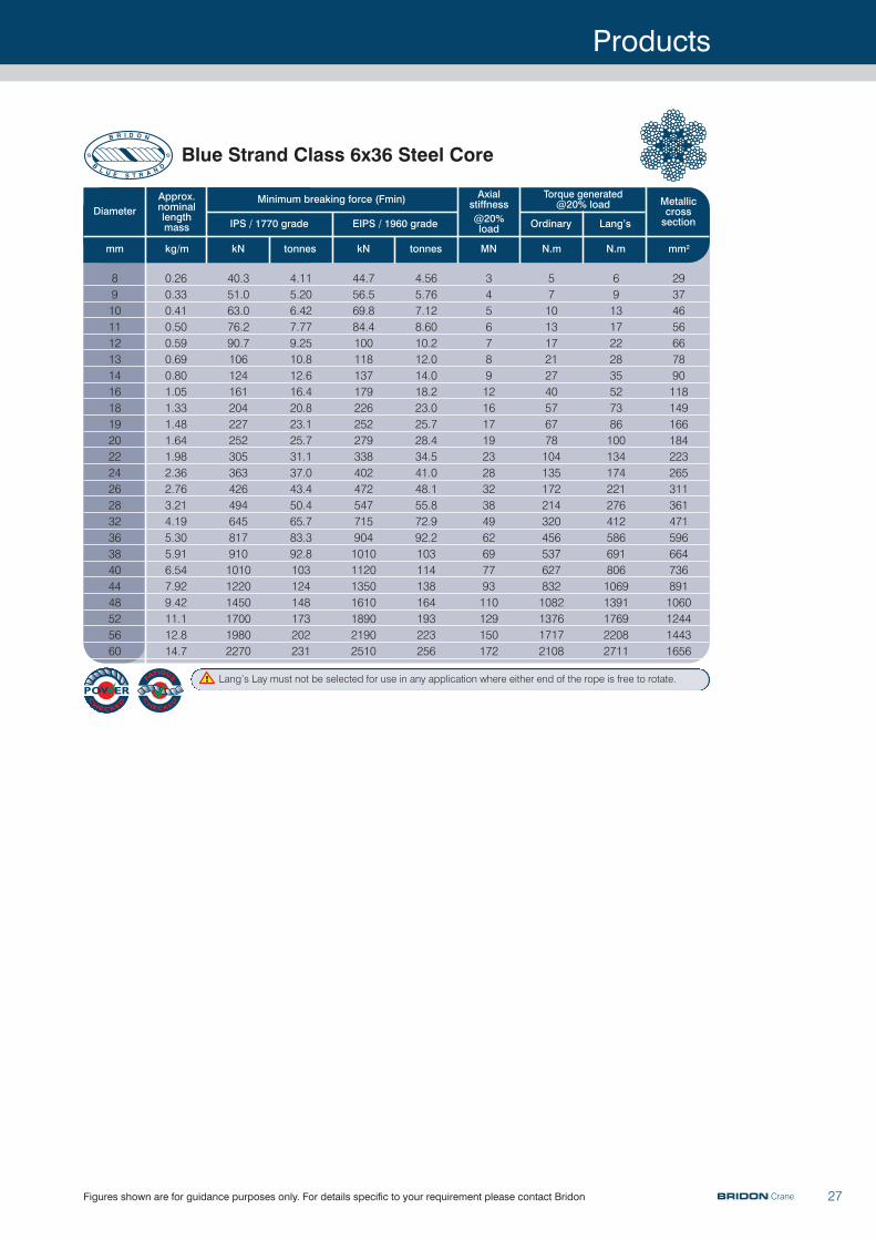
27Figures shown are for guidance purposes only. For details specific to your requirement please contact Bridon
Diameter
mm
IPS / 1770 grade
Minimum breaking force (Fmin)
EIPS / 1960 grade @20% load
Axialstiffness
Torque generated@20% load Metallic
crosssectionLang’s
mm2kg/m kN tonnes kN tonnes MN N.m
Ordinary
N.m
Approx.nominal lengthmass
8910111213141618192022242628323638404448525660
0.260.330.410.500.590.690.801.051.331.481.641.982.362.763.214.195.305.916.547.929.4211.112.814.7
40.351.063.076.290.7106124161204227252305363426494645817910101012201450170019802270
4.115.206.427.779.2510.812.616.420.823.125.731.137.043.450.465.783.392.8103124148173202231
44.756.569.884.41001181371792262522793384024725477159041010112013501610189021902510
4.565.767.128.6010.212.014.018.223.025.728.434.541.048.155.872.992.2103114138164193223256
345678912161719232832384962697793110129150172
571013172127405767781041351722143204565376278321082137617172108
69131722283552738610013417422127641258669180610691391176922082711
293746566678901181491661842232653113614715966647368911060124414431656
Blue Strand Class 6x36 Steel Core
Lang’s Lay must not be selected for use in any application where either end of the rope is free to rotate.
BRIDON Crane
Products
28 Figures shown are for guidance purposes only. For details specific to your requirement please contact BridonBRIDON Crane
Diameter
mm ins
EIPS / 1960 grade
Minimum breaking force (Fmin)
@20% load
Axialstiffness
Torque generated@20% load Metallic
crosssectionOrdinary
mm2kg/m lb/ft kN tonnes tons(200lbs) MN kN.m
Approx. nominal length mass
15.919.122.225.428.631.834.938.141.344.5
5/83/47/811.1/81.1/41.3/81.1/21.5/81.3/4
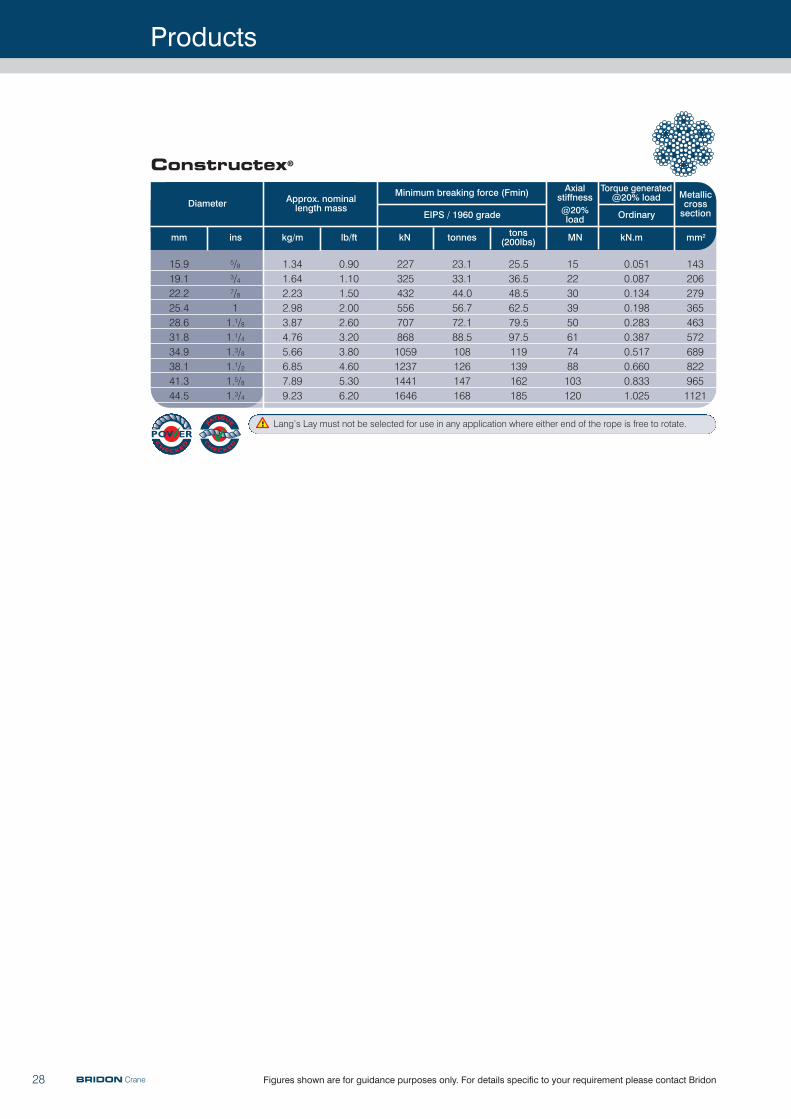
Constructex®
1.341.642.232.983.874.765.666.857.899.23
0.901.101.502.002.603.203.804.605.306.20
2273254325567078681059123714411646
23.133.144.056.772.188.5108126147168
25.536.548.562.579.597.5119139162185
1522303950617488103120
0.0510.0870.1340.1980.2830.3870.5170.6600.8331.025
1432062793654635726898229651121
Lang’s Lay must not be selected for use in any application where either end of the rope is free to rotate.
Terminations
29
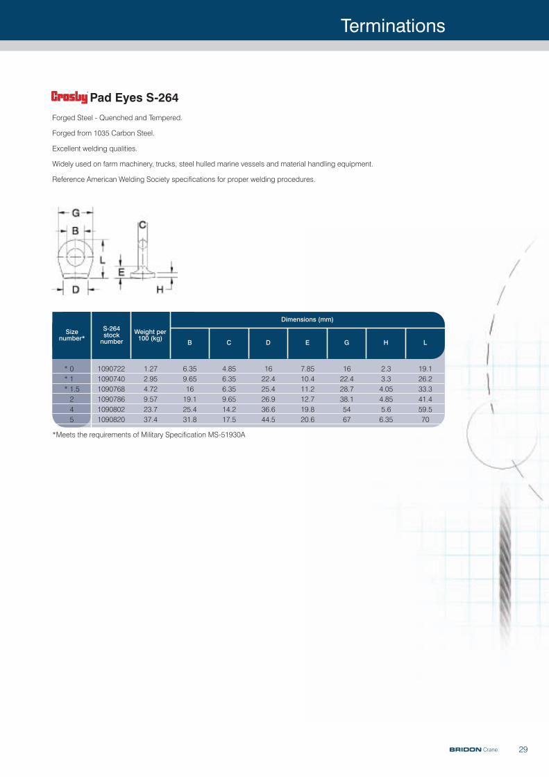
Forged Steel - Quenched and Tempered.
Forged from 1035 Carbon Steel.
Excellent welding qualities.
Widely used on farm machinery, trucks, steel hulled marine vessels and material handling equipment.
Reference American Welding Society specifications for proper welding procedures.
Sizenumber*
S-264 stocknumber
Weight per100 (kg)
B C D E G H L
1.272.954.729.5723.737.4
6.359.651619.125.431.8
4.856.356.359.6514.217.5
1622.425.426.936.644.5
7.8510.411.212.719.820.6
1622.428.738.15467
2.33.34.054.855.66.35
19.126.233.341.459.570
109072210907401090768109078610908021090820
* 0* 1* 1.5245
Pad Eyes S-264
Dimensions (mm)
*Meets the requirements of Military Specification MS-51930A
BRIDON Crane
Terminations
30
Nominal size
(dia of rope)a b c s p
(min) hApproximateweight per 100 pieces
mm mm mm mm mm mm mm kg
4681012141618202224262832364044
5791113161820222426293135404448
912131619222527303337465055606570
101520253035404550556065708090100110
2.12.6456789101011121214161820
5.17.1111416171921232427303338424653
2030405060708090100110120130140160180200220
1.22.85.715.224385266881041292602774404607001000
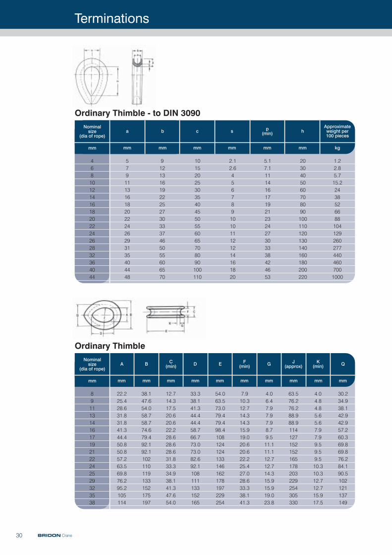
Ordinary Thimble - to DIN 3090
Nominal size
(dia of rope)DC
(min)BA E F(min) G J
(approx)K
(min) Q
mm mm mm mm mm mm mm mm mm mm mm
891113141617192122242529323538
22.225.428.631.831.841.344.450.850.857.263.569.876.295.2105114
38.147.654.058.758.774.679.492.192.1102110119133152175197
12.714.317.520.620.622.228.628.628.631.833.334.938.141.347.654.0
33.338.141.344.444.458.766.773.073.082.692.1108111133152165
54.063.573.079.479.498.4108124124133146162178197229254
7.910.312.714.314.315.919.020.620.622.225.427.028.633.338.141.3
4.06.47.97.97.98.79.511.111.112.712.714.315.915.919.023.8
63.576.276.288.988.9114127152152165178203229254305330
4.04.84.85.65.67.97.99.59.59.510.310.312.712.715.917.5
30.234.938.142.942.957.260.369.869.876.284.190.5102121137149
Ordinary Thimble
BRIDON Crane
Terminations
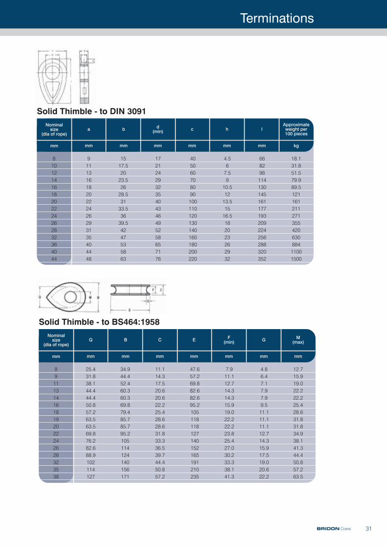
31
Nominal size
(dia of rope)a b d
(min) c h lApproximateweight per 100 pieces
mm mm mm mm mm mm mm kg
81012141618202224262832364044
91113161820222426293135404448
1517.52023.52628.53133.53639.54247535863
172124293235404346495258657176
405060708090100110120130140160180200220
4.567.5910.51213.51516.5182023262932
668298114130145161177193209224256288320352
18.131.851.579.989.512116121127135542063088411001500
Solid Thimble - to DIN 3091
Nominal size
(dia of rope)Q B C E F
(min) G M(max)
mm mm mm mm mm mm mm mm
891113141618192022242628323538
25.431.838.144.444.450.857.263.563.569.876.282.688.9102114127
34.944.452.460.360.369.879.485.785.795.2105114124140156171
11.114.317.520.620.622.225.428.628.631.833.336.539.744.450.857.2
47.657.269.882.682.695.2105118118127140152165191210235
7.911.112.714.314.315.919.022.222.223.825.427.030.233.338.141.3
4.86.47.17.97.99.511.111.111.112.714.315.917.519.020.622.2
12.715.919.022.222.225.428.631.831.834.938.141.344.450.857.263.5
Solid Thimble - to BS464:1958
BRIDON Crane
Terminations
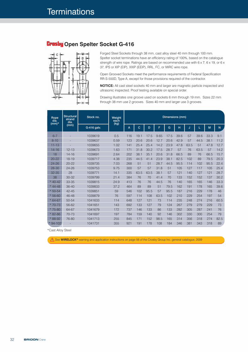
32
Forged Steel Sockets through 38 mm, cast alloy steel 40 mm through 100 mm. Spelter socket terminations have an efficiency rating of 100%, based on the cataloguestrength of wire rope. Ratings are based on recommended use with 6 x 7, 6 x 19, or 6 x37, IPS or XIP (EIP), XXIP (EEIP), RRL, FC, or IWRC wire rope.
Open Grooved Sockets meet the performance requirements of Federal SpecificationRR-S-550D, Type A, except for those provisions required of the contractor.
NOTICE: All cast steel sockets 40 mm and larger are magnetic particle inspected andultrasonic inspected. Proof testing available on special order.
Drawing illustrates one groove used on sockets 6 mm through 19 mm. Sizes 22 mmthrough 38 mm use 2 grooves. Sizes 40 mm and larger use 3 grooves.
Rope dia.(mm)*
Structuralstranddia.(mm)
Stock no.
G-416 galv. A C D F G H J L M N
10396191039637103965510396731039691103971710397351039753103977110397991039815103983310398511039879104163310416511041679104169710417131041731
---
12-1314-1618-1920-2224-262830-3233-3536-4042-4546-4850-5456-6264-6770-7376-80-
6-78-1011-1314-161820-2224-2628-3032-3538
* 40-42* 44-48* 50-54* 56-60* 64-67* 70-73* 75-80* 82-86* 88-92* 94-102
0.50.591.021.632.644.387.039.7514.121.424.937.25976114143172197255355
116123141171202235268300335384413464546597648692737784845921
19.120.625.431.838.144.5515763.5767689102114127133146159171191
17.520.625.430.235.141.4515763.570768995.5108121127133140152178
9.6512.714.217.520.623.928.731.838.141.444.5515763.57379869298.5108
17.520.623.928.731.838.144.55157707679.595.5102114124133146165184
39.642.947.85766.582.595.5105121133140162187210235267282302314346
575763.57689102114127140152165191216229248279305330356381
39.644.55163.57689102117127152165178229254274279287300318343
33.338.147.85766.579.595.5105121137146165178197216229241254274318
9.111.212.714.215.720.322.425.428.730.233.339.6465460.573767982.589
Open Spelter Socket G-416
Weighteach(kg)
Dimensions (mm)
*Cast Alloy Steel
See WIRELOCK® warning and application instructions on page 56 of the Crosby Group Inc. general catalogue, 2009
BRIDON Crane
Terminations
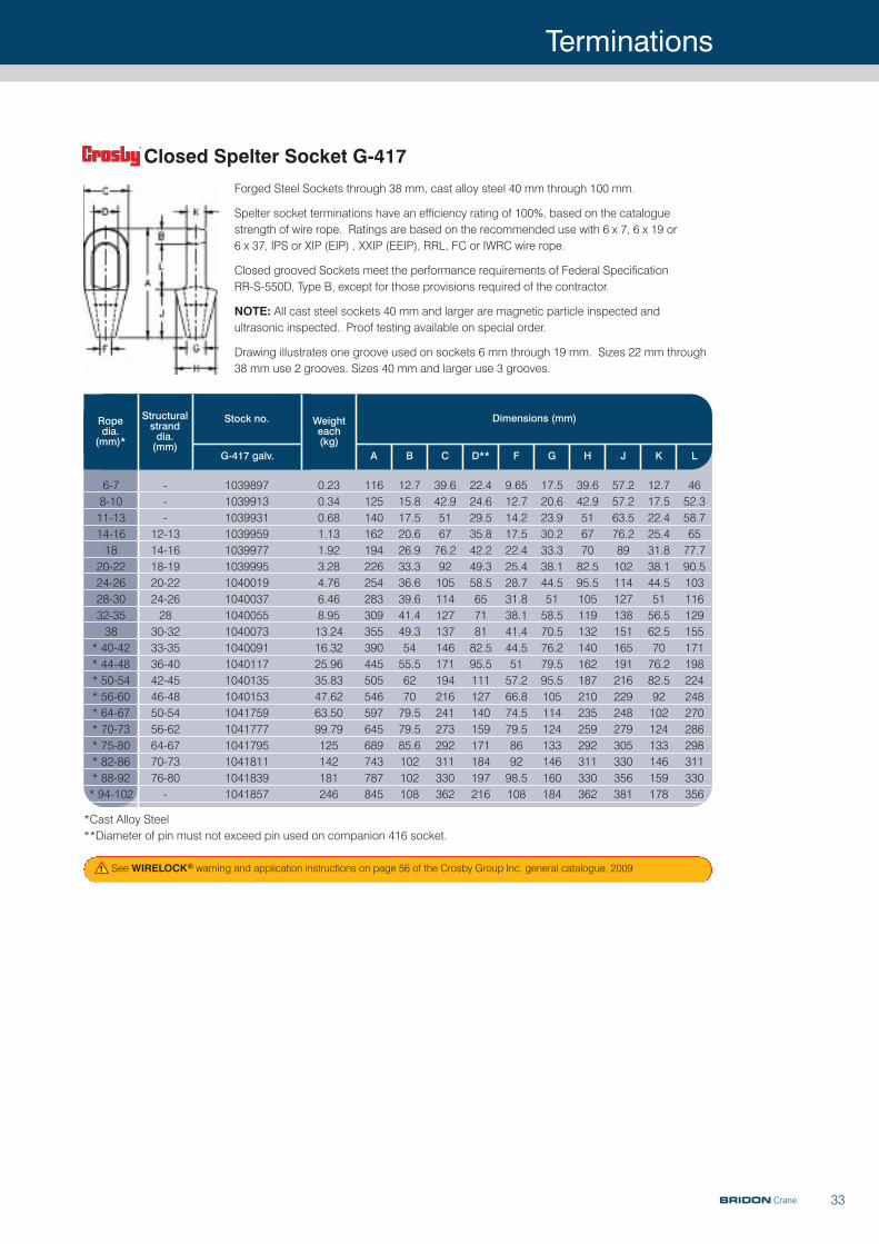
33
Forged Steel Sockets through 38 mm, cast alloy steel 40 mm through 100 mm.
Spelter socket terminations have an efficiency rating of 100%, based on the cataloguestrength of wire rope. Ratings are based on the recommended use with 6 x 7, 6 x 19 or 6 x 37, IPS or XIP (EIP) , XXIP (EEIP), RRL, FC or IWRC wire rope.
Closed grooved Sockets meet the performance requirements of Federal Specification RR-S-550D, Type B, except for those provisions required of the contractor.
NOTE: All cast steel sockets 40 mm and larger are magnetic particle inspected andultrasonic inspected. Proof testing available on special order.
Drawing illustrates one groove used on sockets 6 mm through 19 mm. Sizes 22 mm through38 mm use 2 grooves. Sizes 40 mm and larger use 3 grooves.
Rope dia.(mm)*
Structuralstranddia.(mm)
Stock no.
G-417 galv. A B C D** F G H J K L
10398971039913103993110399591039977103999510400191040037104005510400731040091104011710401351040153104175910417771041795104181110418391041857
---
12-1314-1618-1920-2224-262830-3233-3536-4042-4546-4850-5456-6264-6770-7376-80-
6-78-1011-1314-161820-2224-2628-3032-3538
* 40-42* 44-48* 50-54* 56-60* 64-67* 70-73* 75-80* 82-86* 88-92* 94-102
0.230.340.681.131.923.284.766.468.9513.2416.3225.9635.8347.6263.5099.79125142181246
116125140162194226254283309355390445505546597645689743787845
12.715.817.520.626.933.336.639.641.449.35455.5627079.579.585.6102102108
39.642.9516776.292105114127137146171194216241273292311330362
22.424.629.535.842.249.358.565718182.595.5111127140159171184197216
9.6512.714.217.522.425.428.731.838.141.444.55157.266.874.579.5869298.5108
17.520.623.930.233.338.144.55158.570.576.279.595.5105114124133146160184
39.642.951677082.595.5105119132140162187210235259292311330362
57.257.263.576.289102114127138151165191216229248279305330356381
12.717.522.425.431.838.144.55156.562.57076.282.592102124133146159178
4652.358.76577.790.5103116129155171198224248270286298311330356
Closed Spelter Socket G-417
Weighteach(kg)
Dimensions (mm)
See WIRELOCK® warning and application instructions on page 56 of the Crosby Group Inc. general catalogue, 2009
*Cast Alloy Steel**Diameter of pin must not exceed pin used on companion 416 socket.
BRIDON Crane
Terminations
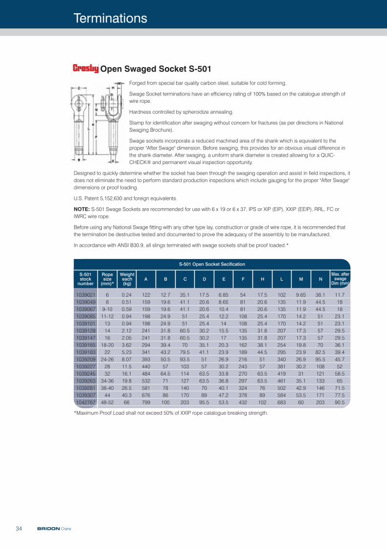
34
S-501stocknumber
Ropesize(mm)*
Weighteach(kg)
A B C D E F H M NL
689-1011-1213141618-202224-26283234-3638-404448-52
0.240.510.590.940.942.122.053.625.238.0711.516.119.826.540.366
122159159198198241241294341393440484532581676799
12.719.619.624.924.931.831.839.443.250.55764.5717886100
35.141.141.1515160.560.57079.593.5103114127140170203
17.520.620.625.425.430.230.235.141.1515763.563.5708995.5
6.858.6510.412.21415.51720.323.926.930.233.836.840.147.253.5
548181108108135135162189216243270297324378432
17.520.620.625.425.431.831.838.144.5515763.563.57689102
102135135170170207207254295340381419461502584683
9.6511.911.914.214.217.317.319.823.926.930.23135.142.953.560
38.144.544.5515157577082.595.5108121133146171203
11.7181823.123.129.529.536.139.445.75258.56571.577.590.5
1039021103904910390671039085103910110391291039147103916510391831039209103922710392451039263103928110393071042767
Open Swaged Socket S-501
S-501 Open Socket Secification
Max. afterswage
Dim (mm)
Forged from special bar quality carbon steel, suitable for cold forming.
Swage Socket terminations have an efficiency rating of 100% based on the catalogue strength ofwire rope.
Hardness controlled by spheroidize annealing.
Stamp for identification after swaging without concern for fractures (as per directions in NationalSwaging Brochure).
Swage sockets incorporate a reduced machined area of the shank which is equivalent to theproper "After Swage" dimension. Before swaging, this provides for an obvious visual difference inthe shank diameter. After swaging, a uniform shank diameter is created allowing for a QUIC-CHECK® and permanent visual inspection opportunity.
Designed to quickly determine whether the socket has been through the swaging operation and assist in field inspections, itdoes not eliminate the need to perform standard production inspections which include gauging for the proper "After Swage"dimensions or proof loading.
U.S. Patent 5,152,630 and foreign equivalents.
NOTE: S-501 Swage Sockets are recommended for use with 6 x 19 or 6 x 37, IPS or XIP (EIP), XXIP (EEIP), RRL, FC orIWRC wire rope.
Before using any National Swage fitting with any other type lay, construction or grade of wire rope, it is recommended thatthe termination be destructive tested and documented to prove the adequacy of the assembly to be manufactured.
In accordance with ANSI B30.9, all slings terminated with swage sockets shall be proof loaded.*
*Maximum Proof Load shall not exceed 50% of XXIP rope catalogue breaking strength.
BRIDON Crane
Terminations
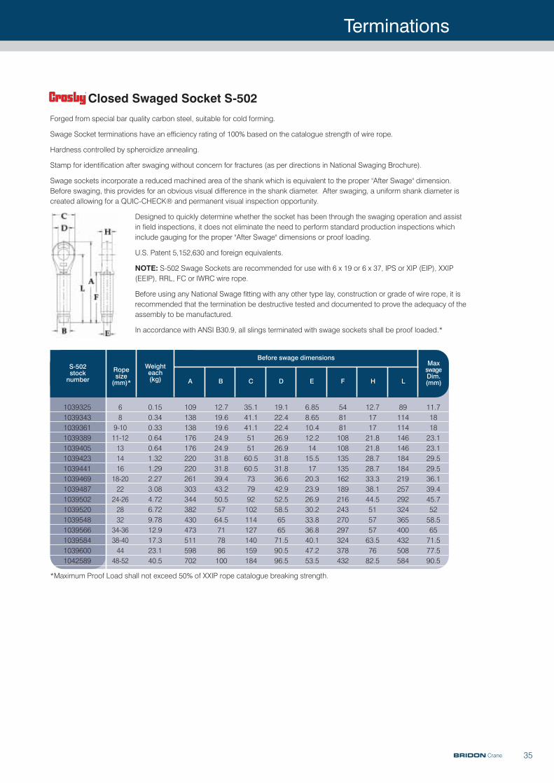
35
S-502stocknumber
Ropesize(mm)*
Weighteach(kg) A B C D E F H
MaxswageDim.(mm)L
1039325103934310393611039389103940510394231039441103946910394871039502103952010395481039566103958410396001042589
689-1011-1213141618-202224-26283234-3638-404448-52
0.150.340.330.640.641.321.292.273.084.726.729.7812.917.323.140.5
109138138176176220220261303344382430473511598702
12.719.619.624.924.931.831.839.443.250.55764.5717886100
35.141.141.1515160.560.5737992102114127140159184
19.122.422.426.926.931.831.836.642.952.558.5656571.590.596.5
6.858.6510.412.21415.51720.323.926.930.233.836.840.147.253.5
548181108108135135162189216243270297324378432
12.7171721.821.828.728.733.338.144.551575763.57682.5
89114114146146184184219257292324365400432508584
11.7181823.123.129.529.536.139.445.75258.56571.577.590.5
Before swage dimensions
Closed Swaged Socket S-502
Forged from special bar quality carbon steel, suitable for cold forming.
Swage Socket terminations have an efficiency rating of 100% based on the catalogue strength of wire rope.
Hardness controlled by spheroidize annealing.
Stamp for identification after swaging without concern for fractures (as per directions in National Swaging Brochure).
Swage sockets incorporate a reduced machined area of the shank which is equivalent to the proper "After Swage" dimension.Before swaging, this provides for an obvious visual difference in the shank diameter. After swaging, a uniform shank diameter iscreated allowing for a QUIC-CHECK® and permanent visual inspection opportunity.
Designed to quickly determine whether the socket has been through the swaging operation and assistin field inspections, it does not eliminate the need to perform standard production inspections whichinclude gauging for the proper "After Swage" dimensions or proof loading.
U.S. Patent 5,152,630 and foreign equivalents.
NOTE: S-502 Swage Sockets are recommended for use with 6 x 19 or 6 x 37, IPS or XIP (EIP), XXIP(EEIP), RRL, FC or IWRC wire rope.
Before using any National Swage fitting with any other type lay, construction or grade of wire rope, it isrecommended that the termination be destructive tested and documented to prove the adequacy of theassembly to be manufactured.
In accordance with ANSI B30.9, all slings terminated with swage sockets shall be proof loaded.*
*Maximum Proof Load shall not exceed 50% of XXIP rope catalogue breaking strength.
BRIDON Crane
Terminations
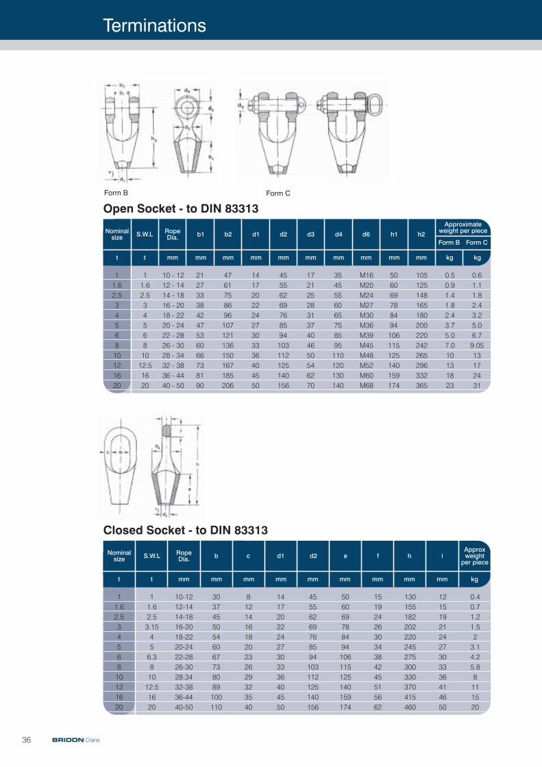
36
Nominal size S.W.L Rope
Dia. b1 b2 d1 d2 d3 d4 d6 h1 h2
t t mm mm mm mm mm mm mm mm mm mm kg kg
Approximateweight per piece
Form B Form C
11.62.53456810121620
11.62.5345681012.51620
10 - 1212 - 1414 - 1816 - 2018 - 2220 - 2422 - 2826 - 3028 - 3432 - 3836 - 4440 - 50
212733384247536066738190
4761758696107121136150167185206
141720222427303336404550
45556269768594103112125140156
172125283137404650546270
3545556065758595110120130140
M16M20M24M27M30M36M39M45M48M52M60M68
506069788494106115125140159174
105125148165180200220242265296332365
0.50.91.41.82.43.75.07.010131823
0.61.11.82.43.25.06.79.0513172431
Open Socket - to DIN 83313Form B Form C
Nominal size S.W.L Rope
Dia. b c d1 d2 e f h i
t t mm mm mm mm mm mm mm mm mm kg
Approxweightper piece
11.62.53456810121620
11.62.53.15456.381012.51620
10-1212-1414-1816-2018-2220-2422-2826-3028.3432-3836-4440-50
30374550546067738089100110
81214161820232629323540
141720222427303336404550
45556269768594103112125140156
506069788494106115125140159174
151924263034384245515662
130155182202220245275300330370415460
121519212427303336414650
0.40.71.21.523.14.25.88111520
Closed Socket - to DIN 83313
BRIDON Crane
37
Terminations
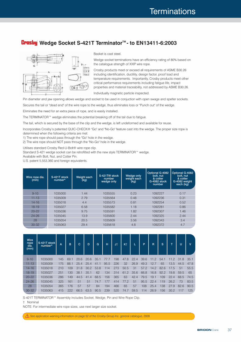
Wire rope dia.(mm)
S-421T stocknumber*
Weight each (kg)
S-421TW stocknumber
wedge only
Wedge onlyweight each
(kg)
Optional G-4082bolt, nut & cotter
G-4082 stocknumber
Optional G-4082bolt, nut & cotter
G-4082 weighteach (kg)
9-1011-1314-1618-1920-2224-262830-32
10350001035009103501810350271035036103504510350541035063
1.442.794.46.589.7513.920.529.4
10355551035564103557310355821035591103560010356091035618
0.230.480.811.181.822.443.564.8
10922271092236109225410922811092307109232510923431092372
0.170.310.520.861.462.443.44.7
Wire rope dia.(mm)
S-421T stocknumber* A B C D G H J† K† L P R S T U V
10350001035009103501810350271035036103504510350541035063
145175210251286325365415
69.188.1109130149161176222
20.625.431.838.144.5515766.5
20.625.430.235.141.4515763.5
35.141.153.86268.574.78490.5
77.795.5114134156177194239
198226273314365414466520
47.83250.561.26377.26574.7
22.426.93135.642.4515759.5
39.649.357.266.879.595.5108114
11.212.714.216.819.122.425.426.9
54.16582.692.2109119138156
11.213.517.519.822.426.227.930.2
31.844.55159.568.57382.6117
35.147.855.56574.583.590.5125
9-1011-1314-1618-1920-2224-262830-32
S-421T TERMINATOR™ Assembly includes Socket, Wedge, Pin and Wire Rope Clip.† NominalNOTE: For intermediate wire rope sizes, use next larger size socket.
See application warning information on page 52 of the Crosby Group Inc. general catalogue, 2009
Basket is cast steel.
Wedge socket terminations have an efficiency rating of 80% based onthe catalogue strength of XXIP wire rope.
Crosby products meet or exceed all requirements of ASME B30.26including identification, ductility, design factor, proof load andtemperature requirements. Importantly, Crosby products meet othercritical performance requirements including fatigue life, impactproperties and material traceability, not addressed by ASME B30.26.
Individually magnetic particle inspected.
Pin diameter and jaw opening allows wedge and socket to be used in conjuction with open swage and spelter sockets.
Secures the tail or "dead end" of the wire rope to the wedge, thus eliminates loss or "Punch out" of the wedge.
Eliminates the need for an extra piece of rope, and is easily installed.
The TERMINATOR™ wedge eliminates the potential breaking off of the tail due to fatigue.
The tail, which is secured by the base of the clip and the wedge, is left undeformed and available for reuse.
Incorporates Crosby’s patented QUIC-CHECK® "Go" and "No-Go" feature cast into the wedge. The proper size rope isdetermined when the following criteria are met: 1) The wire rope should pass through the "Go" hole in the wedge. 2) The wire rope should NOT pass through the "No-Go" hole in the wedge.
Utilises standard Crosby Red-U-Bolt® wire rope clip. Standard S-421 wedge socket can be retrofitted with the new style TERMINATOR™ wedge. Available with Bolt, Nut, and Cotter Pin.U.S. patent 5,553,360 and foreign equivalents.
Wedge Socket S-421T TerminatorTM - to EN13411-6:2003
BRIDON Crane
Terminations
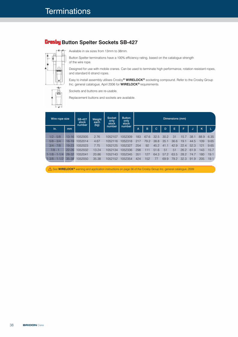
38
Available in six sizes from 13mm to 38mm.
Button Spelter terminations have a 100% efficiency rating, based on the catalogue strength of the wire rope.
Designed for use with mobile cranes. Can be used to terminate high performance, rotation resistant ropes,and standard 6 strand ropes.
Easy to install assembly utilises Crosby® WIRELOCK® socketing compound. Refer to the Crosby GroupInc. general catalogue, April 2006 for WIRELOCK® requirements.
Sockets and buttons are re-usable.
Replacement buttons and sockets are available.
Wire rope size SB-427stocknumber
Weighteach (kg)
In. mm
105200510520141052023105203210520411052050
13-1616-1919-2322-2628-3235-38
1/2 - 5/85/8 - 3/43/4 - 7/87/8 - 1
1-1/8 - 1-1/41-3/8 - 1-1/2
2.764.677.7513.2420.8635.38
105210710521161052125105213410521431052152
105230910523181052327105233610523451052354
183217254298351424
67.679.292111127152
32.538.845.251.664.377
30.235.141.15157.269.9
3136.642.95163.579.2
15.719.122.426.228.232.3
38.144.552.361.974.791.9
88.9109121143180205
6.359.659.6515.719.119.1
Button Spelter Sockets SB-427
Socketonly stocknumber
Buttononly stocknumber
A B C D E F J K L
Dimensions (mm)
See WIRELOCK® warning and application instructions on page 56 of the Crosby Group Inc. general catalogue, 2009
BRIDON Crane
Terminations
39
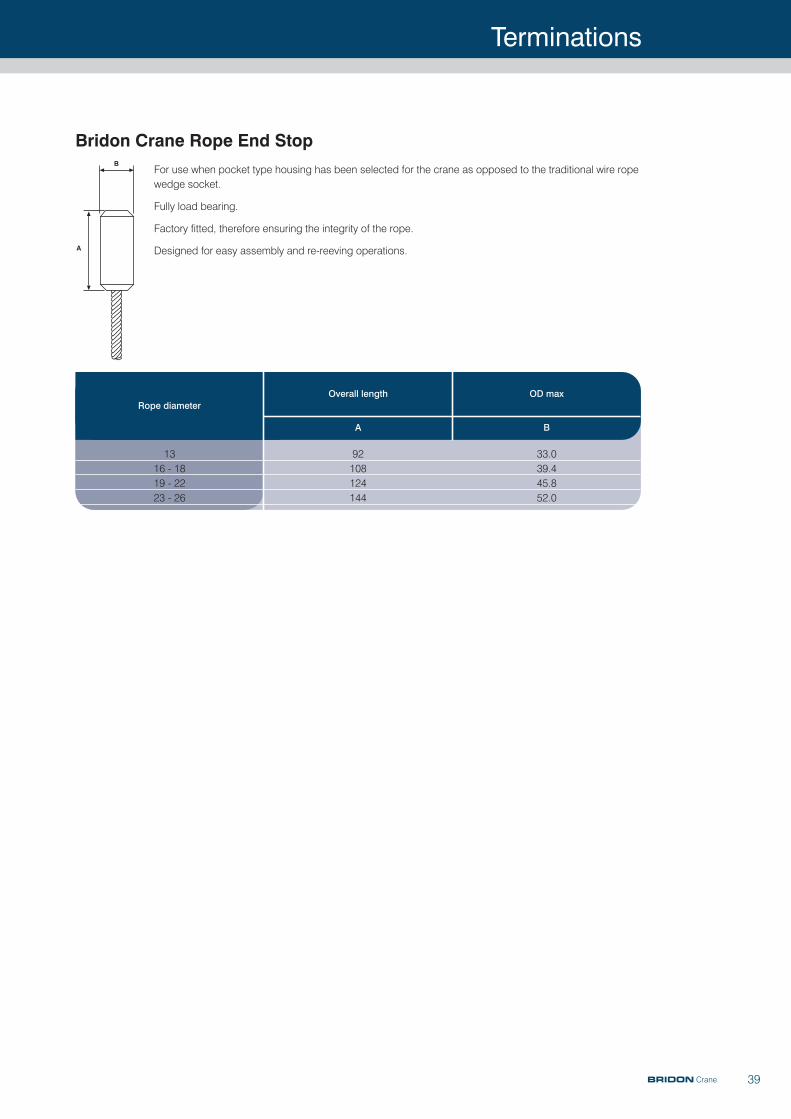
For use when pocket type housing has been selected for the crane as opposed to the traditional wire ropewedge socket.
Fully load bearing.
Factory fitted, therefore ensuring the integrity of the rope.
Designed for easy assembly and re-reeving operations.
Rope diameter
1316 - 1819 - 2223 - 26
92108124144
33.039.445.852.0
Bridon Crane Rope End Stop
OD maxOverall length
BA
BRIDON Crane

40 BRIDON Crane
Services & Training
Non destructive examination (NDE)
The primary cause of wire rope failure is internal degradationthrough corrosion and fatigue. We provide acomprehensives non-destructive examination service,operating to the most meticulous standards. This detects thepresence of defects such as broken wires, both on thesurface and within the rope, loss of metallic cross-sectionalarea and distortions. Results from this examination arerecorded progressively, in digital format, from the surveyhead of the specialist equipment to a notebook or laptop, asthe wire rope passes through the head. The resulting trace isthen analysed and a comprehensive report produced.
Splicing
In addition to any basic splicing requirements, BRIDON areable to offer a variety of specialist splicing abilities, such aslong splicing, to meet our client’s needs.
Such requirements, which are carried out in-situ, mayentail; rope driven conveyors, aerial haulages, funiculars,tile conveyors etc. and may be long splices or eye splices,including multi-strand and bordeaux connection. All splices,including passenger carrying ropes, are carried out tointernationally recognised standards. Where required allsplicing materials, including liquid rubber for injection to thesplice area, can be provided.
TrainingBridon has established a deserved reputation for runninghigh quality training courses, which is no less than would beexpected from a world leader in the design, manufacture andsubsequent use of wire and fibre ropes. Our courses neverstand still and are directly relevant to current legislation,improved technology, and the competitive trading conditionsof today’s markets. In an increasingly competitive world,costs must be continually reduced without compromisingsafety. There is no better way to prepare for this challengethan through a Bridon training course.
For further information on training courses, includingpractical workshop based wire rope splicing and socketingcourses, any of which can be fine tuned to suit yourindividual needs, please contact BRIDON.
Bridon International Services employ some of the mosthighly trained professionals in the industry. Ourunderstanding of, and expertise in dealing with, all mannerof issues related to wire and fibre ropes has enabled us todevelop a wide portfolio of cost effective services which areenjoyed by Bridon customers world-wide.
24 hours a day, 365 days a year, our engineers andtechnicians are dispatched across the globe to provideexpert assistance and solutions, no matter what theproblem, or wherever the location. With resources andsupport services based at key hubs on every continent,BRIDON really does provide a truly International specialistafter sales service in wire and fibre rope.
Repair and Maintenance
Repair and maintenance can be carried out in many forms.All types of ropes including haulage, multi-strand rope,Locked Coil and Spiral Strand are catered for, from abroken wire to a total re-splice.
Installation & Replacement Services
The service life and safety of a wire rope can depend as muchupon the quality of the installation as upon the quality of theproduct itself. To protect your investment, take advantage ofour installation and replacement service - expert internationalsupport covering virtually all types of equipment which uses orincorporates wire rope. Typical installations include: miningapplications, elevators, excavators, cranes and aerialropeways. Bridon Services has a range of specialisedinstallation equipment, such as back tension winches,spoolers and hydraulic tensioners, that can be employed inconjunction with our skilled engineers to ensure installations ofwire rope are carried out correctly, professionally, and aboveall, safely.
Inspection & Statutory Examination Services
We are also able to provide customers with statutoryexamination services, as required under law, whichsubjects wire rope and lifting equipment (“below the hook”)to stringent testing and examination procedures.
Brilube Advanced Rope Dressings
41
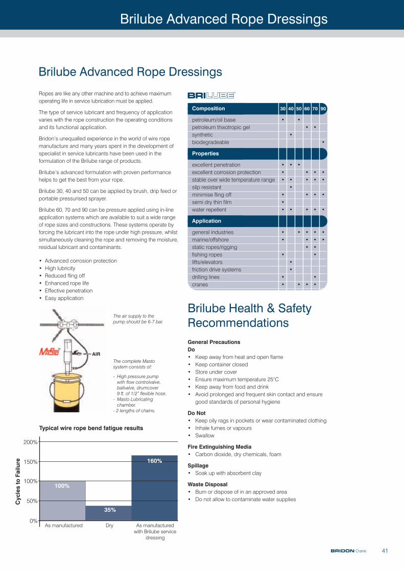
Ropes are like any other machine and to achieve maximumoperating life in service lubrication must be applied.
The type of service lubricant and frequency of applicationvaries with the rope construction the operating conditionsand its functional application.
Bridon’s unequalled experience in the world of wire ropemanufacture and many years spent in the development ofspecialist in service lubricants have been used in theformulation of the Brilube range of products.
Brilube’s advanced formulation with proven performancehelps to get the best from your rope.
Brilube 30, 40 and 50 can be applied by brush, drip feed orportable pressurised sprayer.
Brilube 60, 70 and 90 can be pressure applied using in-lineapplication systems which are available to suit a wide rangeof rope sizes and constructions. These systems operate byforcing the lubricant into the rope under high pressure, whilstsimultaneously cleaning the rope and removing the moisture,residual lubricant and contaminants.
• Advanced corrosion protection• High lubricity• Reduced fling off• Enhanced rope life• Effective penetration• Easy application
Brilube Advanced Rope Dressings
As manufactured Dry As manufacturedwith Brilube service
dressing
200%
150%
100%100%
35%
160%
50%
0%
Typical wire rope bend fatigue results
Cycles to Failure
AIRThe complete Mastosystem consists of:
- High pressure pumpwith flow controlvalve,ballvalve, drumcover 9 ft. of 1/2” flexible hose.
- Masto Lubricatingchamber.
- 2 lengths of chains.
The air supply to thepump should be 6-7 bar.
Composition 30 40 50 60 70 90
petroleum/oil base • •petroleum thixotropic gel • •synthetic •biodegradeable •
Properties
excellent penetration • • •excellent corrosion protection • • • •stable over wide temperature range • • • • •slip resistant •minimise fling off • • • •semi dry thin film •water repellent • • • • •
Application
general industries • • • • •marine/offshore • • • •static ropes/rigging • •fishing ropes • •lifts/elevators •friction drive systems •drilling lines • •cranes • • • •
BRIDON Crane
Brilube Health & SafetyRecommendationsGeneral PrecautionsDo • Keep away from heat and open flame• Keep container closed • Store under cover• Ensure maximum temperature 25°C• Keep away from food and drink• Avoid prolonged and frequent skin contact and ensure
good standards of personal hygiene
Do Not • Keep oily rags in pockets or wear contaminated clothing• Inhale fumes or vapours• Swallow
Fire Extinguishing Media• Carbon dioxide, dry chemicals, foam
Spillage• Soak up with absorbent clay
Waste Disposal• Burn or dispose of in an approved area• Do not allow to contaminate water supplies
Brilube Advanced Rope Dressings
42
Brilube Advanced Rope Dressings
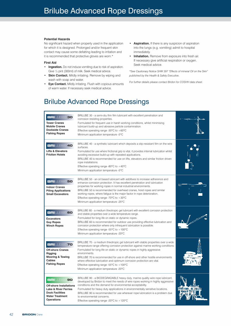
30 BRILUBE 30 - a semi-dry thin film lubricant with excellent penetration andcorrosion resisting properties.Formulated for frequent use in harsh working conditions, whilst minimisinglubricant build-up and abrasive particle contamination.Effective operating range -30ºC to +60ºCMinimum application temperature -5ºC
BRILUBE 40 - a synthetic lubricant which deposits a slip-resistant film on the wiresurfaces.Formulated for use where frictional grip is vital, it provides internal lubrication whilstavoiding excessive build-up with repeated applications.BRILUBE 40 is recommended for use on lifts, elevators and similar friction drivenrope installations.Effective operating range -80ºC to +40ºCMinimum application temperature -5ºC
BRILUBE 50 - an oil based lubricant with additives to increase adherence andenhance corrosion protection. It has excellent penetration and lubricationproperties for working ropes in normal industrial environments.BRILUBE 50 is recommended for overhead cranes, hoist ropes and similarworking ropes, where fatigue is the major factor in rope deterioration.Effective operating range -70ºC to +30ºCMinimum application temperature -25ºC
BRILUBE 60 - a medium thixotropic gel lubricant with excellent corrosion protectionand stable properties over a wide temperature range.Formulated for long life on static or dynamic ropes.BRILUBE 60 is recommended for outdoor use providing effective lubrication andcorrosion protection where only infrequent lubrication is possible.Effective operating range -55ºC to +100ºCMinimum application temperature -20ºC
BRILUBE 70 - a medium thixotropic gel lubricant with stable properties over a widetemperature range offering corrosion protection against marine working conditions.Formulated for long life on static or dynamic ropes in highly aggressiveenvironments.BRILUBE 70 is recommended for use in off-shore and other hostile environmentswhere effective lubrication and optimum corrosion protection are vital.Effective operating range -55ºC to +100ºCMinimum application temperature -20ºC
BRILUBE 90 - a BIODEGRADABLE heavy duty, marine quality wire rope lubricant,developed by Bridon to meet the needs of wire ropes working in highly aggressiveconditions and the demand for environmental acceptability.Formulated for heavy duty applications in environmentally sensitive locations.BRILUBE 90 is recommended for use wherever rope lubrication is a problem dueto environmental concerns.Effective operating range -20ºC to +120ºC
Tower CranesMobile CranesDockside CranesFishing Ropes
Lifts & ElevatorsFriction Hoists
Indoor CranesPiling ApplicationsSmall Excavators
ExcavatorsGuy RopesWinch Ropes
Off-shore CranesRiggingMooring & TowingCablesFishing Ropes
Off-shore InstallationsLake & River FerriesDock FacilitiesWater TreatmentOperations
40
50
60
70
90
Potential Hazards No significant hazard when properly used in the applicationfor which it is designed. Prolonged and/or frequent skincontact may cause some defatting leading to irritation andit is recommended that protective gloves are worn.*
First Aid• Ingestion. Do not induce vomiting due to risk of aspiration.
Give 1/2 pint (300ml) of milk. Seek medical advice.• Skin Contact. Mildly irritating. Remove by wiping and
wash with soap and water.• Eye Contact. Mildly irritating. Flush with copious amounts
of warm water. If necessary seek medical advice.
• Aspiration. If there is any suspicion of aspiration into the lungs (e.g. vomiting) admit to hospitalimmediately.
• Inhalation. Remove from exposure into fresh air. If necessary give artificial respiration or oxygen. Seek medical advice.
*See Cautionary Notice SHW 397 “Effects of mineral Oil on the Skin”
published by the Health & Safety Executive.
For further details please contact Bridon for COSHH data sheet.
BRIDON Crane
Technical Information
43
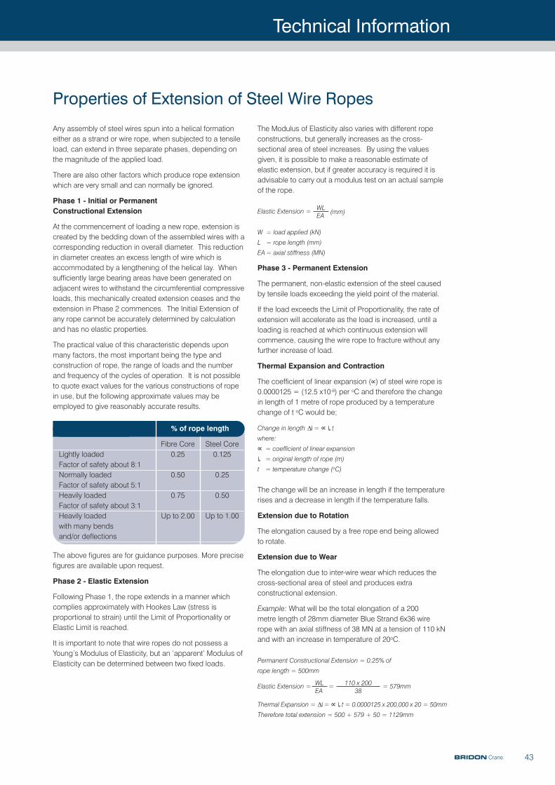
Any assembly of steel wires spun into a helical formationeither as a strand or wire rope, when subjected to a tensileload, can extend in three separate phases, depending onthe magnitude of the applied load.
There are also other factors which produce rope extensionwhich are very small and can normally be ignored.
Phase 1 - Initial or Permanent Constructional Extension
At the commencement of loading a new rope, extension iscreated by the bedding down of the assembled wires with acorresponding reduction in overall diameter. This reductionin diameter creates an excess length of wire which isaccommodated by a lengthening of the helical lay. Whensufficiently large bearing areas have been generated onadjacent wires to withstand the circumferential compressiveloads, this mechanically created extension ceases and theextension in Phase 2 commences. The Initial Extension ofany rope cannot be accurately determined by calculationand has no elastic properties.
The practical value of this characteristic depends uponmany factors, the most important being the type andconstruction of rope, the range of loads and the numberand frequency of the cycles of operation. It is not possibleto quote exact values for the various constructions of ropein use, but the following approximate values may beemployed to give reasonably accurate results.
The above figures are for guidance purposes. More precisefigures are available upon request.
Phase 2 - Elastic Extension
Following Phase 1, the rope extends in a manner whichcomplies approximately with Hookes Law (stress isproportional to strain) until the Limit of Proportionality orElastic Limit is reached.
It is important to note that wire ropes do not possess aYoung’s Modulus of Elasticity, but an ‘apparent’ Modulus ofElasticity can be determined between two fixed loads.
The Modulus of Elasticity also varies with different ropeconstructions, but generally increases as the cross-sectional area of steel increases. By using the valuesgiven, it is possible to make a reasonable estimate ofelastic extension, but if greater accuracy is required it isadvisable to carry out a modulus test on an actual sampleof the rope.
Elastic Extension =
W = load applied (kN)
L = rope length (mm)
EA= axial stiffness (MN)
Phase 3 - Permanent Extension
The permanent, non-elastic extension of the steel causedby tensile loads exceeding the yield point of the material.
If the load exceeds the Limit of Proportionality, the rate ofextension will accelerate as the load is increased, until aloading is reached at which continuous extension willcommence, causing the wire rope to fracture without anyfurther increase of load.
Thermal Expansion and Contraction
The coefficient of linear expansion (∝) of steel wire rope is0.0000125 = (12.5 x10⁻⁶) per oC and therefore the changein length of 1 metre of rope produced by a temperaturechange of t oC would be;
Change in length ∆| = ∝ |o t
where:
∝ = coefficient of linear expansion
|o = original length of rope (m)
t = temperature change (oC)
The change will be an increase in length if the temperaturerises and a decrease in length if the temperature falls.
Extension due to Rotation
The elongation caused by a free rope end being allowed to rotate.
Extension due to Wear
The elongation due to inter-wire wear which reduces thecross-sectional area of steel and produces extraconstructional extension.
Example: What will be the total elongation of a 200 metre length of 28mm diameter Blue Strand 6x36 wire rope with an axial stiffness of 38 MN at a tension of 110 kNand with an increase in temperature of 20oC.
Permanent Constructional Extension = 0.25% of
rope length = 500mm
Elastic Extension = = = 579mm
Thermal Expansion = ∆| = ∝ |o t = 0.0000125 x 200,000 x 20 = 50mm
Therefore total extension = 500 + 579 + 50 = 1129mm
Properties of Extension of Steel Wire Ropes
WL (mm)EA
WLEA
110 x 20038
% of rope length
Fibre Core Steel CoreLightly loaded 0.25 0.125Factor of safety about 8:1Normally loaded 0.50 0.25Factor of safety about 5:1Heavily loaded 0.75 0.50Factor of safety about 3:1Heavily loaded Up to 2.00 Up to 1.00with many bends and/or deflections
BRIDON Crane
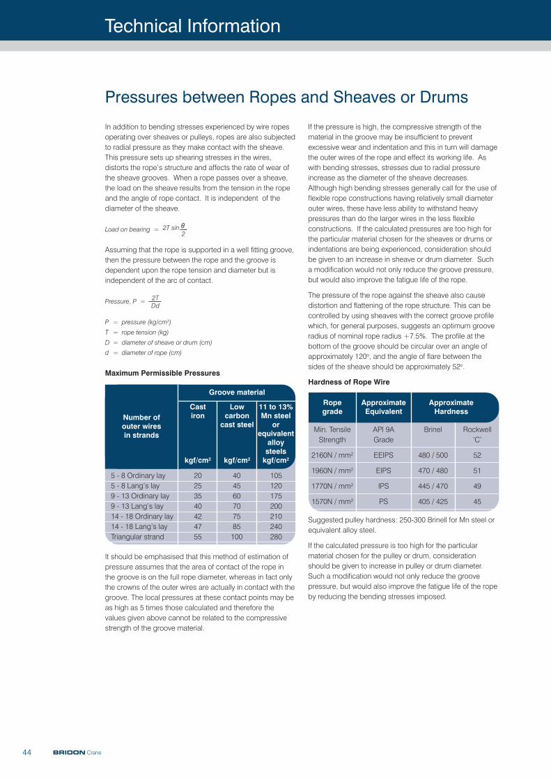
Technical Information
44 BRIDON Crane
In addition to bending stresses experienced by wire ropesoperating over sheaves or pulleys, ropes are also subjectedto radial pressure as they make contact with the sheave.This pressure sets up shearing stresses in the wires,distorts the rope’s structure and affects the rate of wear ofthe sheave grooves. When a rope passes over a sheave,the load on the sheave results from the tension in the ropeand the angle of rope contact. It is independent of thediameter of the sheave.
Load on bearing =
Assuming that the rope is supported in a well fitting groove,then the pressure between the rope and the groove isdependent upon the rope tension and diameter but isindependent of the arc of contact.
Pressure, P =
P = pressure (kg/cm2)
T = rope tension (kg)
D = diameter of sheave or drum (cm)
d = diameter of rope (cm)
Maximum Permissible Pressures
It should be emphasised that this method of estimation ofpressure assumes that the area of contact of the rope inthe groove is on the full rope diameter, whereas in fact onlythe crowns of the outer wires are actually in contact with thegroove. The local pressures at these contact points may beas high as 5 times those calculated and therefore thevalues given above cannot be related to the compressivestrength of the groove material.
If the pressure is high, the compressive strength of thematerial in the groove may be insufficient to preventexcessive wear and indentation and this in turn will damagethe outer wires of the rope and effect its working life. Aswith bending stresses, stresses due to radial pressureincrease as the diameter of the sheave decreases.Although high bending stresses generally call for the use offlexible rope constructions having relatively small diameterouter wires, these have less ability to withstand heavypressures than do the larger wires in the less flexibleconstructions. If the calculated pressures are too high forthe particular material chosen for the sheaves or drums orindentations are being experienced, consideration shouldbe given to an increase in sheave or drum diameter. Sucha modification would not only reduce the groove pressure,but would also improve the fatigue life of the rope.
The pressure of the rope against the sheave also causedistortion and flattening of the rope structure. This can becontrolled by using sheaves with the correct groove profilewhich, for general purposes, suggests an optimum grooveradius of nominal rope radius +7.5%. The profile at thebottom of the groove should be circular over an angle ofapproximately 120o, and the angle of flare between thesides of the sheave should be approximately 52o.
Hardness of Rope Wire
Suggested pulley hardness: 250-300 Brinell for Mn steel orequivalent alloy steel.
If the calculated pressure is too high for the particularmaterial chosen for the pulley or drum, considerationshould be given to increase in pulley or drum diameter.Such a modification would not only reduce the groovepressure, but would also improve the fatigue life of the ropeby reducing the bending stresses imposed.
Pressures between Ropes and Sheaves or Drums
2T sin θ2
2TDd
Min. TensileStrength
2160N / mm2
1960N / mm2
1770N / mm2
1570N / mm2
API 9AGrade
EEIPS
EIPS
IPS
PS
Brinel
480 / 500
470 / 480
445 / 470
405 / 425
Rockwell‘C’
52
51
49
45
Ropegrade
ApproximateEquivalent
ApproximateHardness
5 - 8 Ordinary lay5 - 8 Lang’s lay9 - 13 Ordinary lay9 - 13 Lang’s lay14 - 18 Ordinary lay14 - 18 Lang’s layTriangular strand
20253540424755
404560707585100
105120175200210240280
Number of outer wiresin strands
Groove material
Castiron
kgf/cm2
Lowcarboncast steel
kgf/cm2
11 to 13%Mn steel
orequivalentalloysteelskgf/cm2
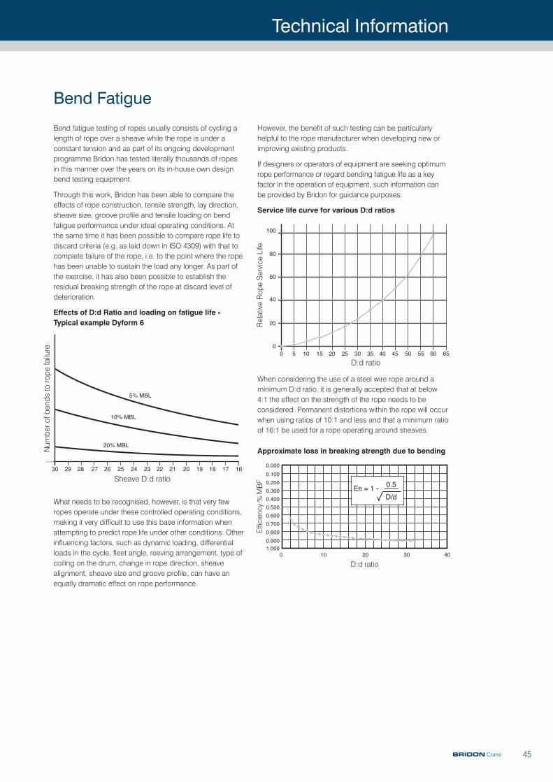
Technical Information
45
Bend fatigue testing of ropes usually consists of cycling alength of rope over a sheave while the rope is under aconstant tension and as part of its ongoing developmentprogramme Bridon has tested literally thousands of ropesin this manner over the years on its in-house own designbend testing equipment.
Through this work, Bridon has been able to compare theeffects of rope construction, tensile strength, lay direction,sheave size, groove profile and tensile loading on bendfatigue performance under ideal operating conditions. Atthe same time it has been possible to compare rope life todiscard criteria (e.g. as laid down in ISO 4309) with that tocomplete failure of the rope, i.e. to the point where the ropehas been unable to sustain the load any longer. As part ofthe exercise, it has also been possible to establish theresidual breaking strength of the rope at discard level ofdeterioration.
Effects of D:d Ratio and loading on fatigue life -Typical example Dyform 6
What needs to be recognised, however, is that very fewropes operate under these controlled operating conditions,making it very difficult to use this base information whenattempting to predict rope life under other conditions. Otherinfluencing factors, such as dynamic loading, differentialloads in the cycle, fleet angle, reeving arrangement, type ofcoiling on the drum, change in rope direction, sheavealignment, sheave size and groove profile, can have anequally dramatic effect on rope performance.
However, the benefit of such testing can be particularlyhelpful to the rope manufacturer when developing new orimproving existing products.
If designers or operators of equipment are seeking optimumrope performance or regard bending fatigue life as a keyfactor in the operation of equipment, such information canbe provided by Bridon for guidance purposes.
Service life curve for various D:d ratios
When considering the use of a steel wire rope around aminimum D:d ratio, it is generally accepted that at below4:1 the effect on the strength of the rope needs to beconsidered. Permanent distortions within the rope will occurwhen using ratios of 10:1 and less and that a minimum ratioof 16:1 be used for a rope operating around sheaves.
Approximate loss in breaking strength due to bending
Bend Fatigue
Number of bends to rope failure
30 29 28 27 26
5% MBL
10% MBL
20% MBL
25 24 23 22 21 20 19 18 17 16
D:d ratio0
100
60
40
20
0
5 10 15 20 25 30 35 40 45 50 55 60 65
80Relative Rope Service Life
Efficiency % MBF
1.0000 10 20 30 40
0.900
0.800
0.700
0.600
0.500
0.400
0.300
0.200
0.100
0.000
D:d ratio
EB = 1 -0.5
D/d
Sheave D:d ratio
BRIDON Crane
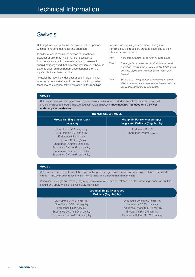
Technical Information
46 BRIDON Crane
Rotating loads can put at risk the safety of those personswithin a lifting zone during a lifting operation.
In order to reduce the risk of rotation the machinerydesigner or user may find it may be necessary toincorporate a swivel in the reeving system; however, itshould be recognised that excessive rotation could have anadverse effect on rope performance depending on therope’s rotational characteristics.
To assist the machinery designer or user in determiningwhether or not a swivel should be used in a lifting system,the following guidance, taking into account the rope type,
construction and lay type and direction, is given. For simplicity, the ropes are grouped according to theirrotational characteristics.
Note 1: A swivel should not be used when installing a rope.
Note 2: Further guidance on the use of swivels with six strand
and rotation-resistant ropes is given in ISO 4308 ‘Cranes
and lifting appliances - selection of wire ropes - part 1
General’.
Note 3: Swivels have varying degrees of efficiency and may be
either an independent accessory or an integral part of a
lifting accessory such as a crane hook.
Swivels
Group 1
Both sets of ropes in this group have high values of rotation when loaded and must not be used unless both ends of the rope are fixed and prevented from rotating however they must NOT be used with a swivel, under any circumstances.
Blue Strand 6x19 Lang’s layBlue Strand 6x36 Lang’s layEndurance 8 Lang’s layEndurance 8PI Lang’s lay
Endurance Dyform 8 Lang’s layEndurance Dyform 8PI Lang’s layEndurance Dyform 6 Lang’s layEndurance Dyform 6PI Lang’s lay
Endurance DSC 8 Endurance Dyform DSC 8
DO NOT USE A SWIVEL
Group 1a: Single layer ropesLang’s lay
Group 1b: Parallel-closed ropesLang’s and Ordinary (Regular) lay
Group 2
With one end free to rotate, all of the ropes in this group will generate less rotation when loaded than those listed inGroup 1. However, such ropes are still likely to unlay and distort under this condition.
When used in single part reeving they may require a swivel to prevent rotation in certain operating conditions but thisshould only apply when employee safety is an issue.
Blue Strand 6x19 Ordinary layBlue Strand 6x36 Ordinary layEndurance 8 Ordinary lay
Endurance Dyform 6 Ordinary layEndurance Dyform 6PI Ordinary lay
Endurance Dyform 8 Ordinary layEndurance 8PI Ordinary lay
Endurance Dyform 8PI Ordinary layEndurance 6FS Ordinary lay
Endurance Dyform 6FS Ordinary lay
Group 2: Single layer ropesOrdinary (Regular) lay
Technical Information
47
Group 3
The ropes in this group incorporate a centre which is laid in the opposite direction to that of the outer strands andare specifically designed to have a medium amount of resistance to rotation.
If it is necessary to use a swivel with any of these ropes in single part reeving to prevent rotation of the load, therope should operate within the normal design factor of 5, not be subject to any shock loading and be checked dailyfor any evidence of distortion.
Where any of these ropes are used in multi-part reeving, the use of an anti-friction swivel at the outboard anchorpoint is not recommended. However, a swivel which can be locked may be useful when optimising the reeving,following rope installation or after subsequent changes to the reeving arrangement.
It should be noted that if a swivel is used in conjunction with these ropes, the bending fatigue life may be reduceddue to increased internal deterioration between the outer strands and the underlying layer.
Endurance 18 Endurance Dyform 18 Endurance 18PI
Group 3: Rotation-resistant ropesLang’s and Ordinary (Regular) lay
Group 4
The ropes in this group are designed to have extremely low levels of rotation when loaded and, if necessary, mayoperate with a swivel in both single and multi-part reeving systems.
Any induced rotation which might normally result from any fleet angle or loads cycle effect would be expected to berelieved when the rope is used with a swivel.
Testing has also shown that when used with a swivel at normal design factor of 5 and zero fleet angle, no reduction ineither rope breaking force or bending fatigue life would be expected.
Endurance 35LS Endurance Dyform 34LR Endurance Dyform 34LRPI
Group 4: Low rotation ropes
Swivels
BRIDON Crane
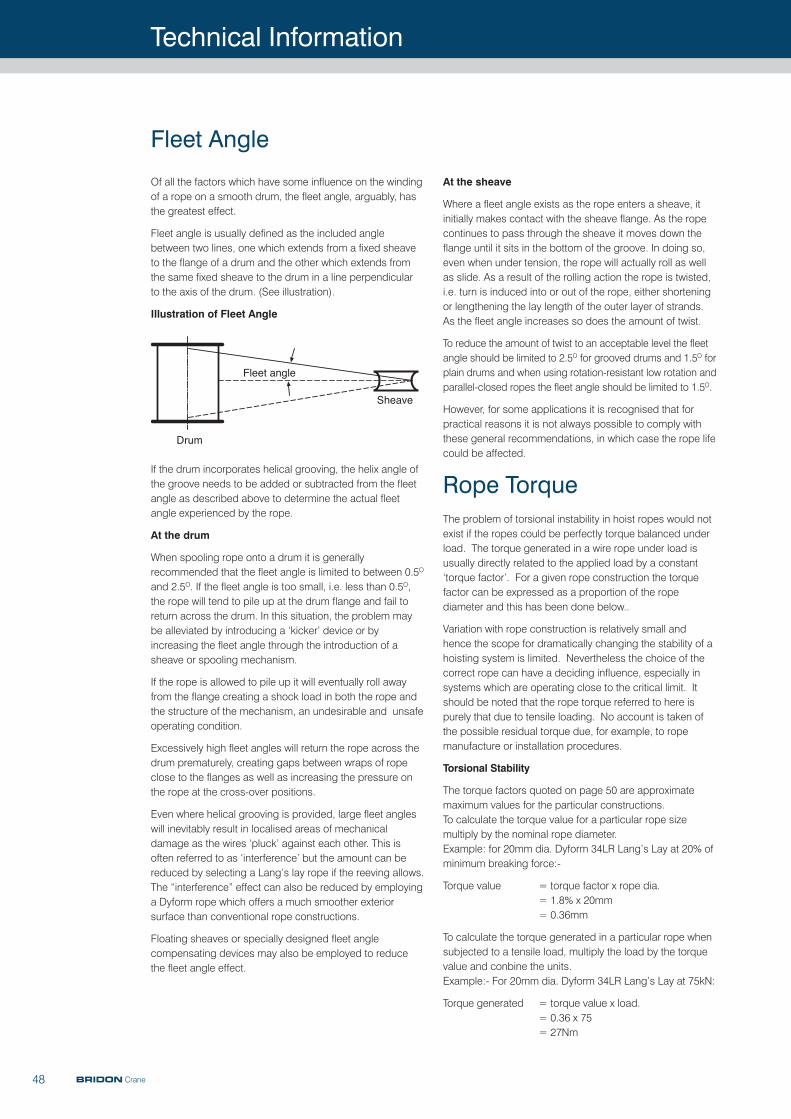
Technical Information
48 BRIDON Crane
Of all the factors which have some influence on the windingof a rope on a smooth drum, the fleet angle, arguably, hasthe greatest effect.
Fleet angle is usually defined as the included anglebetween two lines, one which extends from a fixed sheaveto the flange of a drum and the other which extends fromthe same fixed sheave to the drum in a line perpendicularto the axis of the drum. (See illustration).
Illustration of Fleet Angle
If the drum incorporates helical grooving, the helix angle ofthe groove needs to be added or subtracted from the fleetangle as described above to determine the actual fleetangle experienced by the rope.
At the drum
When spooling rope onto a drum it is generallyrecommended that the fleet angle is limited to between 0.5O
and 2.5O. If the fleet angle is too small, i.e. less than 0.5O,the rope will tend to pile up at the drum flange and fail toreturn across the drum. In this situation, the problem maybe alleviated by introducing a ‘kicker’ device or byincreasing the fleet angle through the introduction of asheave or spooling mechanism.
If the rope is allowed to pile up it will eventually roll awayfrom the flange creating a shock load in both the rope andthe structure of the mechanism, an undesirable and unsafeoperating condition.
Excessively high fleet angles will return the rope across thedrum prematurely, creating gaps between wraps of ropeclose to the flanges as well as increasing the pressure onthe rope at the cross-over positions.
Even where helical grooving is provided, large fleet angleswill inevitably result in localised areas of mechanicaldamage as the wires ‘pluck’ against each other. This isoften referred to as ‘interference’ but the amount can bereduced by selecting a Lang’s lay rope if the reeving allows.The “interference” effect can also be reduced by employinga Dyform rope which offers a much smoother exteriorsurface than conventional rope constructions.
Floating sheaves or specially designed fleet anglecompensating devices may also be employed to reducethe fleet angle effect.
At the sheave
Where a fleet angle exists as the rope enters a sheave, itinitially makes contact with the sheave flange. As the ropecontinues to pass through the sheave it moves down theflange until it sits in the bottom of the groove. In doing so,even when under tension, the rope will actually roll as wellas slide. As a result of the rolling action the rope is twisted,i.e. turn is induced into or out of the rope, either shorteningor lengthening the lay length of the outer layer of strands.As the fleet angle increases so does the amount of twist.
To reduce the amount of twist to an acceptable level the fleetangle should be limited to 2.5O for grooved drums and 1.5O forplain drums and when using rotation-resistant low rotation andparallel-closed ropes the fleet angle should be limited to 1.5O.
However, for some applications it is recognised that forpractical reasons it is not always possible to comply withthese general recommendations, in which case the rope lifecould be affected.
Rope TorqueThe problem of torsional instability in hoist ropes would notexist if the ropes could be perfectly torque balanced underload. The torque generated in a wire rope under load isusually directly related to the applied load by a constant‘torque factor’. For a given rope construction the torquefactor can be expressed as a proportion of the ropediameter and this has been done below..
Variation with rope construction is relatively small andhence the scope for dramatically changing the stability of ahoisting system is limited. Nevertheless the choice of thecorrect rope can have a deciding influence, especially insystems which are operating close to the critical limit. Itshould be noted that the rope torque referred to here ispurely that due to tensile loading. No account is taken ofthe possible residual torque due, for example, to ropemanufacture or installation procedures.
Torsional Stability
The torque factors quoted on page 50 are approximatemaximum values for the particular constructions. To calculate the torque value for a particular rope sizemultiply by the nominal rope diameter. Example: for 20mm dia. Dyform 34LR Lang’s Lay at 20% ofminimum breaking force:-
Torque value = torque factor x rope dia.= 1.8% x 20mm= 0.36mm
To calculate the torque generated in a particular rope whensubjected to a tensile load, multiply the load by the torquevalue and conbine the units. Example:- For 20mm dia. Dyform 34LR Lang’s Lay at 75kN:
Torque generated = torque value x load.= 0.36 x 75= 27Nm
Fleet Angle
Fleet angle
Drum
Sheave
Fleet angle
Drum
Sheave
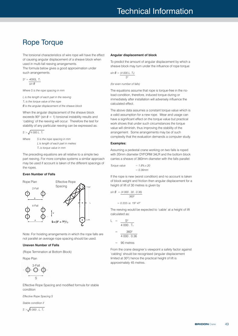
Technical Information
49
The torsional characteristics of wire rope will have the effectof causing angular displacement of a sheave block whenused in multi-fall reeving arrangements. The formula below gives a good approximation under such arrangements.
S2 = 4000L. Tv
sin θ�
Where S is the rope spacing in mm
L is the length of each part in the reeving
Tv is the torque value of the rope
θ is the angular displacement of the sheave block
When the angular displacement of the sheave blockexceeds 90O (sin θ = 1) torsional instability results and‘cabling’ of the reeving will occur. Therefore the test forstability of any particular reeving can be expressed as:
S > 4 000 L. Tv
Where S is the rope spacing in mm
L is length of each part in metres
Tv is torque value in mm
The preceding equations are all relative to a simple twopart reeving. For more complex systems a similar approachmay be used if account is taken of the different spacings ofthe ropes.
Even Number of Falls
Note: For hoisting arrangements in which the rope falls arenot parallel an average rope spacing should be used.
Uneven Number of Falls
(Rope Termination at Bottom Block)
Rope Plan
Effective Rope Spacing and modified formula for stablecondition
Effective Rope Spacing S
Stable condition if
S > 6 000 . L. Tv
Angular displacement of block
To predict the amount of angular displacement by which asheave block may turn under the influence of rope torque:
sin θ = (4 000 L. Tv)S2
(for even number of falls)
The equations assume that rope is torque-free in the no-load condition, therefore, induced torque during orimmediately after installation will adversely influence thecalculated effect.
The above data assumes a constant torque value which isa valid assumption for a new rope. Wear and usage canhave a significant effect on the torque value but practicalwork shows that under such circumstances the torquevalue will diminish, thus improving the stability of thearrangement. Some arrangements may be of suchcomplexity that the evaluation demands a computer study.
Examples:
Assuming a pedestal crane working on two falls is ropedwith 20mm diameter DYFORM 34LR and the bottom blockcarries a sheave of 360mm diameter with the falls parallel:
Torque value = 1.8% x 20
= 0.36mm
If the rope is new (worst condition) and no account is takenof block weight and friction then angular displacement for aheight of lift of 30 metres is given by
sin θ = (4 000 . 30 . 0.36)
3602
= 0.333 i.e. 19O 47’
The reeving would be expected to ‘cable’ at a height of liftcalculated as:
L = S2
4 000 . Tv
= 3602
4 000 . 0.36
= 90 metres
From the crane designer’s viewpoint a safety factor against‘cabling’ should be recognised (angular displacementlimited at 30O) hence the practical height of lift isapproximately 45 metres.
Rope Torque
Effective RopeSpacing
Rope Plan
2-Fall
4-Fall
3-Fall
S
BRIDON Crane
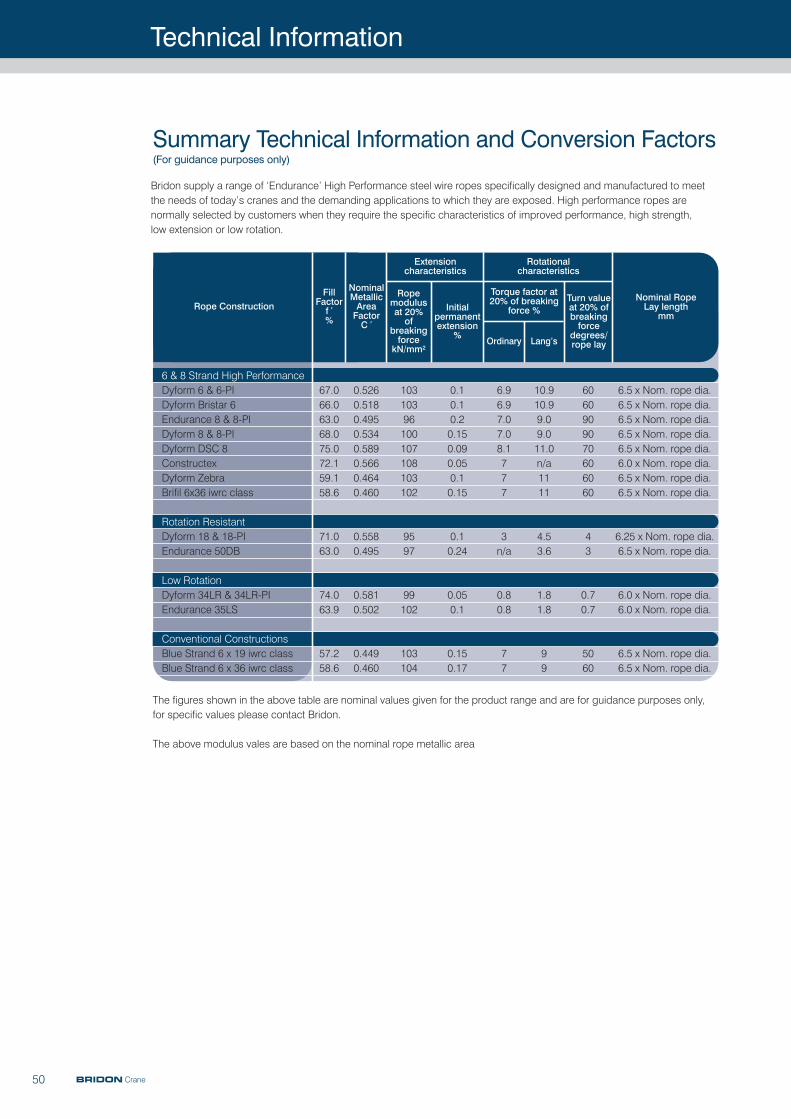
Technical Information
50 BRIDON Crane
Bridon supply a range of ‘Endurance’ High Performance steel wire ropes specifically designed and manufactured to meetthe needs of today’s cranes and the demanding applications to which they are exposed. High performance ropes arenormally selected by customers when they require the specific characteristics of improved performance, high strength, low extension or low rotation.
Summary Technical Information and Conversion Factors(For guidance purposes only)
Rope ConstructionFill
Factorf ’%
NominalMetallicAreaFactorC ’
Ropemodulusat 20%of
breakingforcekN/mm2
Initialpermanentextension
%
Torque factor at20% of breaking
force %
Ordinary Lang’s
Turn valueat 20% ofbreakingforce
degrees/rope lay
Nominal Rope Lay length
mm
6 & 8 Strand High PerformanceDyform 6 & 6-PIDyform Bristar 6Endurance 8 & 8-PIDyform 8 & 8-PIDyform DSC 8ConstructexDyform ZebraBrifil 6x36 iwrc class
Rotation ResistantDyform 18 & 18-PIEndurance 50DB
Low RotationDyform 34LR & 34LR-PIEndurance 35LS
Conventional ConstructionsBlue Strand 6 x 19 iwrc classBlue Strand 6 x 36 iwrc class
6.5 x Nom. rope dia.6.5 x Nom. rope dia.6.5 x Nom. rope dia.6.5 x Nom. rope dia.6.5 x Nom. rope dia.6.0 x Nom. rope dia.6.5 x Nom. rope dia.6.5 x Nom. rope dia.
6.25 x Nom. rope dia.6.5 x Nom. rope dia.
6.0 x Nom. rope dia.6.0 x Nom. rope dia.
6.5 x Nom. rope dia.6.5 x Nom. rope dia.
67.066.063.068.075.072.159.158.6
71.063.0
74.063.9
57.258.6
0.5260.5180.4950.5340.5890.5660.4640.460
0.5580.495
0.5810.502
0.4490.460
10310396100107108103102
9597
99102
103104
0.10.10.20.150.090.050.10.15
0.10.24
0.050.1
0.150.17
6.96.97.07.08.1777
3n/a
0.80.8
77
10.910.99.09.011.0n/a1111
4.53.6
1.81.8
99
6060909070606060
43
0.70.7
5060
Rotationalcharacteristics
Extensioncharacteristics
The figures shown in the above table are nominal values given for the product range and are for guidance purposes only,for specific values please contact Bridon.
The above modulus vales are based on the nominal rope metallic area
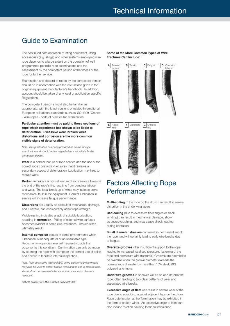
Technical Information
51
Some of the More Common Types of Wire Fractures Can Include:
Factors Affecting RopePerformanceMulti-coiling of the rope on the drum can result in severedistortion in the underlying layers.
Bad coiling (due to excessive fleet angles or slackwinding) can result in mechanical damage, shown as severe crushing, and may cause shock loading during operation.
Small diameter sheaves can result in permanent set ofthe rope, and will certainly lead to early wire breaks due to fatigue.
Oversize grooves offer insufficient support to the ropeleading to increased localised pressure, flattening of therope and premature wire fractures. Grooves are deemed tobe oversize when the groove diameter exceeds the nominal rope diameter by more than 15% steel, 20%polyurethane liners.
Undersize grooves in sheaves will crush and deform therope, often leading to two clear patterns of wear andassociated wire breaks.
Excessive angle of fleet can result in severe wear of therope due to scrubbing against adjacent laps on the drum.Rope deterioration at the Termination may be exhibited inthe form of broken wires. An excessive angle of fleet canalso induce rotation causing torsional imbalance.
The continued safe operation of lifting equipment, liftingaccessories (e.g. slings) and other systems employing wirerope depends to a large extent on the operation of wellprogrammed periodic rope examinations and theassessment by the competent person of the fitness of therope for further service.
Examination and discard of ropes by the competent personshould be in accordance with the instructions given in theoriginal equipment manufacturer’s handbook. In addition,account should be taken of any local or application specificRegulations.
The competent person should also be familiar, asappropriate, with the latest versions of related International,European or National standards such as ISO 4309 “Cranes- Wire ropes - code of practice for examination.
Particular attention must be paid to those sections ofrope which experience has shown to be liable todeterioration. Excessive wear, broken wires,distortions and corrosion are the more commonvisible signs of deterioration.
Note: This publication has been prepared as an aid for rope
examination and should not be regarded as a substitute for the
competent person.
Wear is a normal feature of rope service and the use of thecorrect rope construction ensures that it remains asecondary aspect of deterioration. Lubrication may help toreduce wear.
Broken wires are a normal feature of rope service towardsthe end of the rope’s life, resulting from bending fatigueand wear. The local break up of wires may indicate somemechanical fault in the equipment. Correct lubrication inservice will increase fatigue performance.
Distortions are usually as a result of mechanical damage,and if severe, can considerably affect rope strength.
Visible rusting indicates a lack of suitable lubrication,resulting in corrosion. Pitting of external wire surfacesbecomes evident in some circumstances. Broken wiresultimately result.
Internal corrosion occurs in some environments whenlubrication is inadequate or of an unsuitable type.Reduction in rope diameter will frequently guide theobserver to this condition. Confirmation can only be madeby opening the rope with clamps or the correct use of spikeand needle to facilitate internal inspection.
Note: Non-destructive testing (NDT) using electromagnetic means
may also be used to detect broken wires and/or loss in metallic area.
This method complements the visual examination but does not
replace it.
Pictures courtesy of S.M.R.E. Crown Copyright 1966
Guide to Examination
A Severedby wear
B Tension C Fatigue D Corrosionfatigue
E Plasticwear
F Martensite G Shearedend
BRIDON Crane
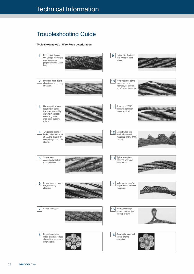
Technical Information
52 BRIDON Crane
Troubleshooting Guide
Mechanical damagedue to rope movementover sharp edgeprojection whilst underload.
1 Typical wire fracturesas a result of bendfatigue.
9
Localised wear due toabrasion on supportingstructure.
2 Wire fractures at thestrand, or coreinterface, as distinctfrom ‘crown’ fractures.
10
Narrow path of wearresulting in fatiguefractures, caused byworking in a grosslyoversize groove, orover small supportrollers.
3 Break up of IWRCresulting from highstress application.
11
Two parallel paths ofbroken wires indicativeof bending through anundersize groove in thesheave.
4 Looped wires as aresult of torsionalimbalance and/or shockloading.
12
Severe wear,associated with hightread pressure.
5 Typical example oflocalised wear anddeformation.
13
Severe wear in Lang’sLay, caused byabrasion.
6 Multi strand rope ‘birdcaged’ due to torsionalimbalance.
14
Severe corrosion.7 Protrusion of ropecentre resulting frombuild up of turn.
15
Internal corrosionwhilst external surfaceshows little evidence ofdeterioration.
8 Substantial wear andsevere internalcorrosion.
16
Typical examples of Wire Rope deterioration
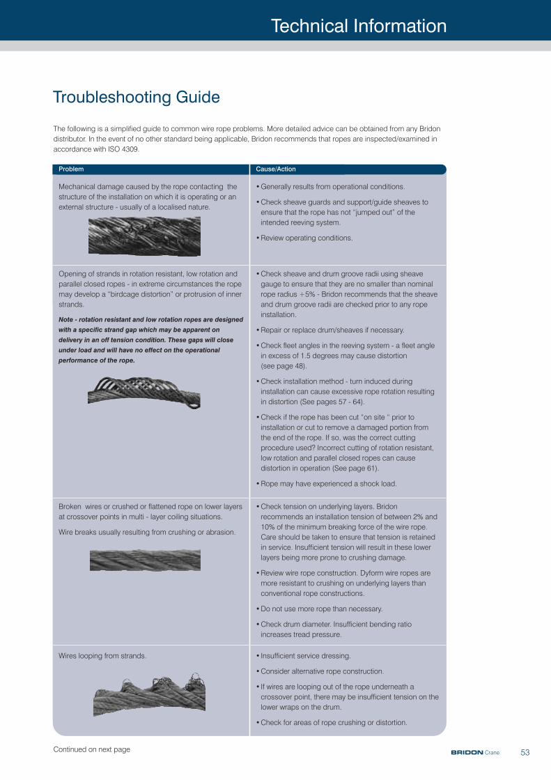
Technical Information
53
Troubleshooting Guide
Mechanical damage caused by the rope contacting thestructure of the installation on which it is operating or anexternal structure - usually of a localised nature.
•Generally results from operational conditions.
•Check sheave guards and support/guide sheaves toensure that the rope has not “jumped out” of theintended reeving system.
•Review operating conditions.
Opening of strands in rotation resistant, low rotation andparallel closed ropes - in extreme circumstances the ropemay develop a “birdcage distortion” or protrusion of innerstrands.
Note - rotation resistant and low rotation ropes are designed
with a specific strand gap which may be apparent on
delivery in an off tension condition. These gaps will close
under load and will have no effect on the operational
performance of the rope.
•Check sheave and drum groove radii using sheavegauge to ensure that they are no smaller than nominalrope radius +5% - Bridon recommends that the sheaveand drum groove radii are checked prior to any ropeinstallation.
•Repair or replace drum/sheaves if necessary.
•Check fleet angles in the reeving system - a fleet anglein excess of 1.5 degrees may cause distortion(see page 48).
•Check installation method - turn induced duringinstallation can cause excessive rope rotation resultingin distortion (See pages 57 - 64).
•Check if the rope has been cut “on site “ prior toinstallation or cut to remove a damaged portion fromthe end of the rope. If so, was the correct cuttingprocedure used? Incorrect cutting of rotation resistant,low rotation and parallel closed ropes can causedistortion in operation (See page 61).
•Rope may have experienced a shock load.
Broken wires or crushed or flattened rope on lower layersat crossover points in multi - layer coiling situations.
Wire breaks usually resulting from crushing or abrasion.
•Check tension on underlying layers. Bridonrecommends an installation tension of between 2% and10% of the minimum breaking force of the wire rope.Care should be taken to ensure that tension is retainedin service. Insufficient tension will result in these lowerlayers being more prone to crushing damage.
•Review wire rope construction. Dyform wire ropes aremore resistant to crushing on underlying layers thanconventional rope constructions.
•Do not use more rope than necessary.
•Check drum diameter. Insufficient bending ratioincreases tread pressure.
The following is a simplified guide to common wire rope problems. More detailed advice can be obtained from any Bridondistributor. In the event of no other standard being applicable, Bridon recommends that ropes are inspected/examined inaccordance with ISO 4309.
Problem Cause/Action
Wires looping from strands. • Insufficient service dressing.
•Consider alternative rope construction.
• If wires are looping out of the rope underneath acrossover point, there may be insufficient tension on thelower wraps on the drum.
•Check for areas of rope crushing or distortion.
BRIDON CraneContinued on next page
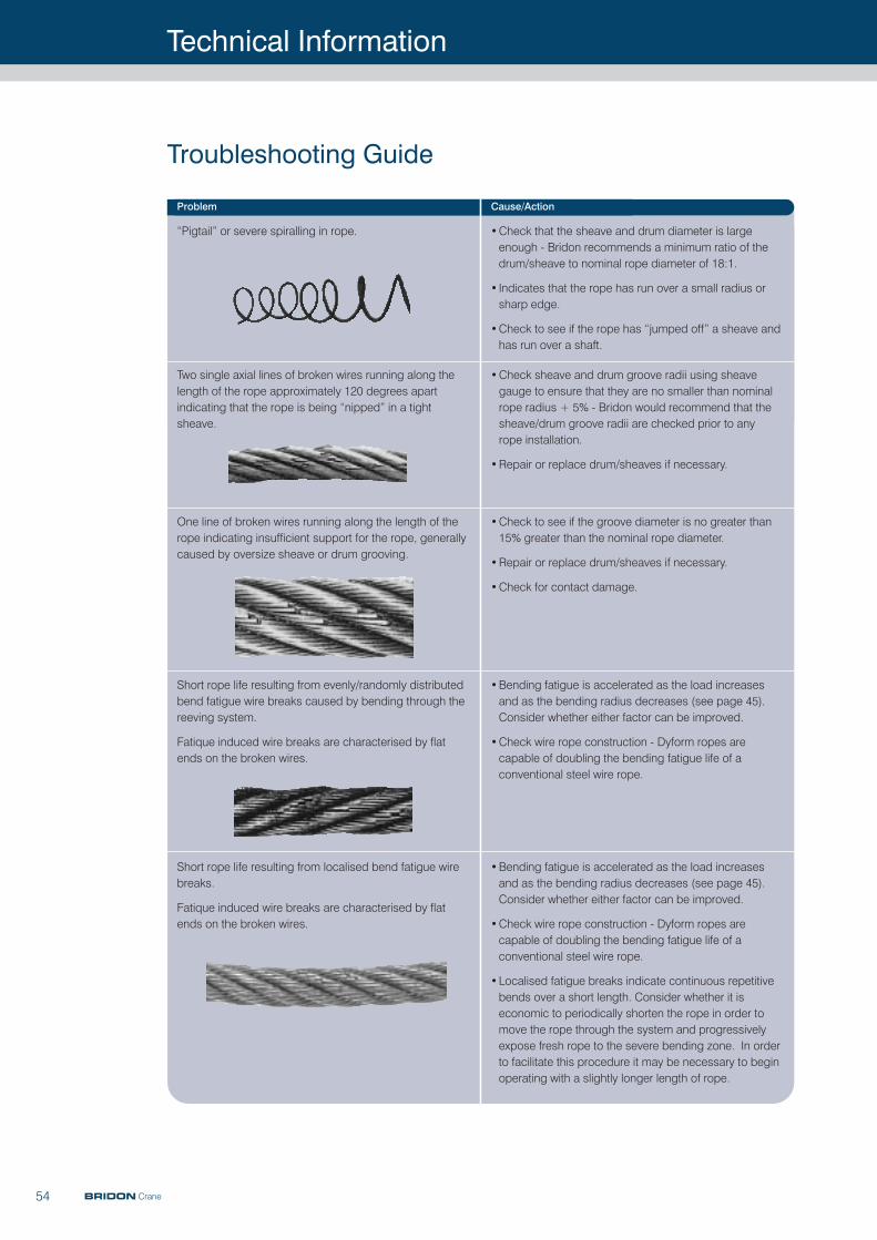
Technical Information
54
Problem Cause/Action
“Pigtail” or severe spiralling in rope. •Check that the sheave and drum diameter is largeenough - Bridon recommends a minimum ratio of thedrum/sheave to nominal rope diameter of 18:1.
• Indicates that the rope has run over a small radius orsharp edge.
•Check to see if the rope has “jumped off” a sheave andhas run over a shaft.
Two single axial lines of broken wires running along thelength of the rope approximately 120 degrees apartindicating that the rope is being “nipped” in a tightsheave.
•Check sheave and drum groove radii using sheavegauge to ensure that they are no smaller than nominalrope radius + 5% - Bridon would recommend that thesheave/drum groove radii are checked prior to any rope installation.
•Repair or replace drum/sheaves if necessary.
One line of broken wires running along the length of therope indicating insufficient support for the rope, generallycaused by oversize sheave or drum grooving.
•Check to see if the groove diameter is no greater than15% greater than the nominal rope diameter.
•Repair or replace drum/sheaves if necessary.
•Check for contact damage.
Short rope life resulting from evenly/randomly distributedbend fatigue wire breaks caused by bending through thereeving system.
Fatique induced wire breaks are characterised by flatends on the broken wires.
•Bending fatigue is accelerated as the load increasesand as the bending radius decreases (see page 45).Consider whether either factor can be improved.
•Check wire rope construction - Dyform ropes arecapable of doubling the bending fatigue life of aconventional steel wire rope.
Troubleshooting Guide
Short rope life resulting from localised bend fatigue wirebreaks.
Fatique induced wire breaks are characterised by flatends on the broken wires.
•Bending fatigue is accelerated as the load increasesand as the bending radius decreases (see page 45).Consider whether either factor can be improved.
•Check wire rope construction - Dyform ropes arecapable of doubling the bending fatigue life of aconventional steel wire rope.
•Localised fatigue breaks indicate continuous repetitivebends over a short length. Consider whether it iseconomic to periodically shorten the rope in order tomove the rope through the system and progressivelyexpose fresh rope to the severe bending zone. In orderto facilitate this procedure it may be necessary to beginoperating with a slightly longer length of rope.
BRIDON Crane
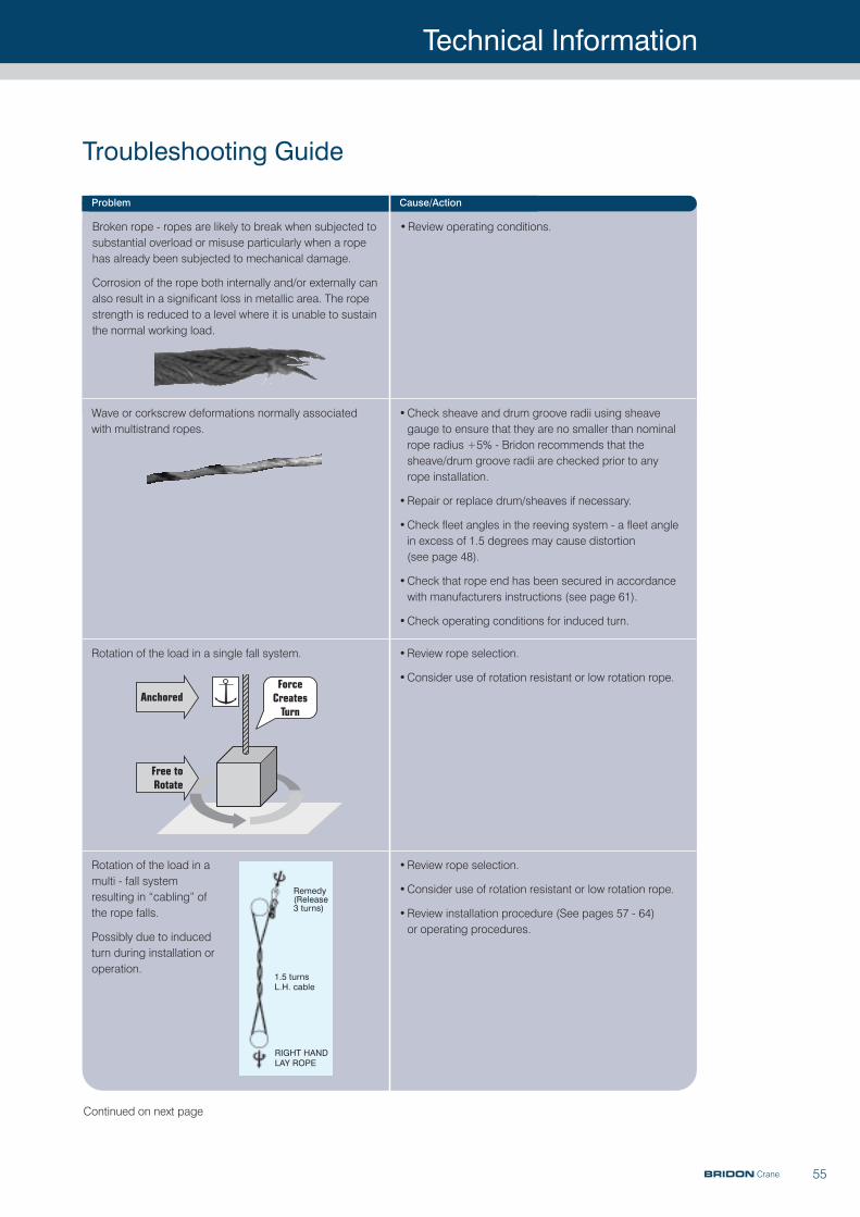
Technical Information
55
Problem Cause/Action
Wave or corkscrew deformations normally associatedwith multistrand ropes.
•Check sheave and drum groove radii using sheavegauge to ensure that they are no smaller than nominalrope radius +5% - Bridon recommends that thesheave/drum groove radii are checked prior to any rope installation.
•Repair or replace drum/sheaves if necessary.
•Check fleet angles in the reeving system - a fleet anglein excess of 1.5 degrees may cause distortion (see page 48).
•Check that rope end has been secured in accordancewith manufacturers instructions (see page 61).
•Check operating conditions for induced turn.
Rotation of the load in a single fall system. •Review rope selection.
•Consider use of rotation resistant or low rotation rope.
Rotation of the load in amulti - fall systemresulting in “cabling” ofthe rope falls.
Possibly due to inducedturn during installation oroperation.
•Review rope selection.
•Consider use of rotation resistant or low rotation rope.
•Review installation procedure (See pages 57 - 64)or operating procedures.
Broken rope - ropes are likely to break when subjected tosubstantial overload or misuse particularly when a ropehas already been subjected to mechanical damage.
Corrosion of the rope both internally and/or externally canalso result in a significant loss in metallic area. The ropestrength is reduced to a level where it is unable to sustainthe normal working load.
•Review operating conditions.
Troubleshooting Guide
Anchored
Free toRotate
ForceCreates
Turn
Remedy(Release3 turns)
1.5 turnsL.H. cable
RIGHT HANDLAY ROPE
Continued on next page
BRIDON Crane
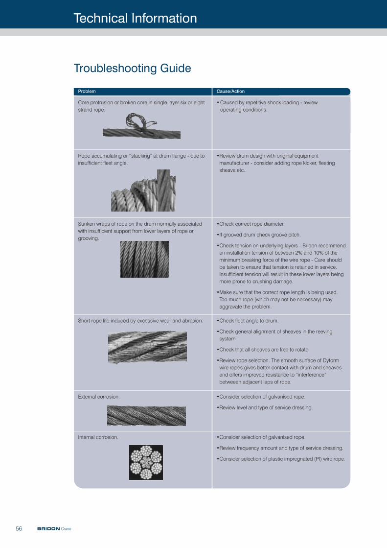
56 BRIDON Crane
Technical Information
Troubleshooting Guide
Problem Cause/Action
External corrosion. •Consider selection of galvanised rope.
•Review level and type of service dressing.
Internal corrosion. •Consider selection of galvanised rope.
•Review frequency amount and type of service dressing.
•Consider selection of plastic impregnated (PI) wire rope.
Short rope life induced by excessive wear and abrasion. •Check fleet angle to drum.
•Check general alignment of sheaves in the reevingsystem.
•Check that all sheaves are free to rotate.
•Review rope selection. The smooth surface of Dyformwire ropes gives better contact with drum and sheavesand offers improved resistance to “interference”betweeen adjacent laps of rope.
Sunken wraps of rope on the drum normally associatedwith insufficient support from lower layers of rope orgrooving.
•Check correct rope diameter.
•If grooved drum check groove pitch.
•Check tension on underlying layers - Bridon recommendan installation tension of between 2% and 10% of theminimum breaking force of the wire rope - Care shouldbe taken to ensure that tension is retained in service.Insufficient tension will result in these lower layers beingmore prone to crushing damage.
•Make sure that the correct rope length is being used.Too much rope (which may not be necessary) mayaggravate the problem.
Rope accumulating or “stacking” at drum flange - due toinsufficient fleet angle.
•Review drum design with original equipmentmanufacturer - consider adding rope kicker, fleetingsheave etc.
Core protrusion or broken core in single layer six or eightstrand rope.
•Caused by repetitive shock loading - review operating conditions.
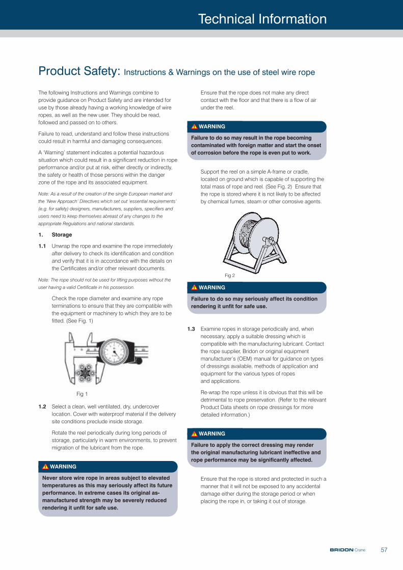
Technical Information
57
Ensure that the rope does not make any direct contact with the floor and that there is a flow of airunder the reel.
WARNING
Failure to do so may result in the rope becomingcontaminated with foreign matter and start the onsetof corrosion before the rope is even put to work.
Support the reel on a simple A-frame or cradle,located on ground which is capable of supporting thetotal mass of rope and reel. (See Fig. 2) Ensure thatthe rope is stored where it is not likely to be affectedby chemical fumes, steam or other corrosive agents.
WARNING
Failure to do so may seriously affect its conditionrendering it unfit for safe use.
1.3 Examine ropes in storage periodically and, whennecessary, apply a suitable dressing which iscompatible with the manufacturing lubricant. Contactthe rope supplier, Bridon or original equipmentmanufacturer’s (OEM) manual for guidance on typesof dressings available, methods of application andequipment for the various types of ropes and applications.
Re-wrap the rope unless it is obvious that this will bedetrimental to rope preservation. (Refer to the relevantProduct Data sheets on rope dressings for moredetailed information.)
WARNING
Failure to apply the correct dressing may renderthe original manufacturing lubricant ineffective andrope performance may be significantly affected.
Ensure that the rope is stored and protected in such amanner that it will not be exposed to any accidentaldamage either during the storage period or whenplacing the rope in, or taking it out of storage.
The following Instructions and Warnings combine toprovide guidance on Product Safety and are intended foruse by those already having a working knowledge of wireropes, as well as the new user. They should be read,followed and passed on to others.
Failure to read, understand and follow these instructionscould result in harmful and damaging consequences.
A ‘Warning’ statement indicates a potential hazardoussituation which could result in a significant reduction in ropeperformance and/or put at risk, either directly or indirectly,the safety or health of those persons within the dangerzone of the rope and its associated equipment.
Note: As a result of the creation of the single European market and
the ‘New Approach’ Directives which set out ‘essential requirements’
(e.g. for safety) designers, manufacturers, suppliers, specifiers and
users need to keep themselves abreast of any changes to the
appropriate Regulations and national standards.
1. Storage
1.1 Unwrap the rope and examine the rope immediatelyafter delivery to check its identification and conditionand verify that it is in accordance with the details onthe Certificates and/or other relevant documents.
Note: The rope should not be used for lifting purposes without the
user having a valid Certificate in his possession.
Check the rope diameter and examine any ropeterminations to ensure that they are compatible withthe equipment or machinery to which they are to befitted. (See Fig. 1)
1.2 Select a clean, well ventilated, dry, undercoverlocation. Cover with waterproof material if the deliverysite conditions preclude inside storage.
Rotate the reel periodically during long periods ofstorage, particularly in warm environments, to preventmigration of the lubricant from the rope.
WARNING
Never store wire rope in areas subject to elevatedtemperatures as this may seriously affect its futureperformance. In extreme cases its original as-manufactured strength may be severely reducedrendering it unfit for safe use.
Product Safety: Instructions & Warnings on the use of steel wire rope
Fig 1
Fig 2
BRIDON Crane
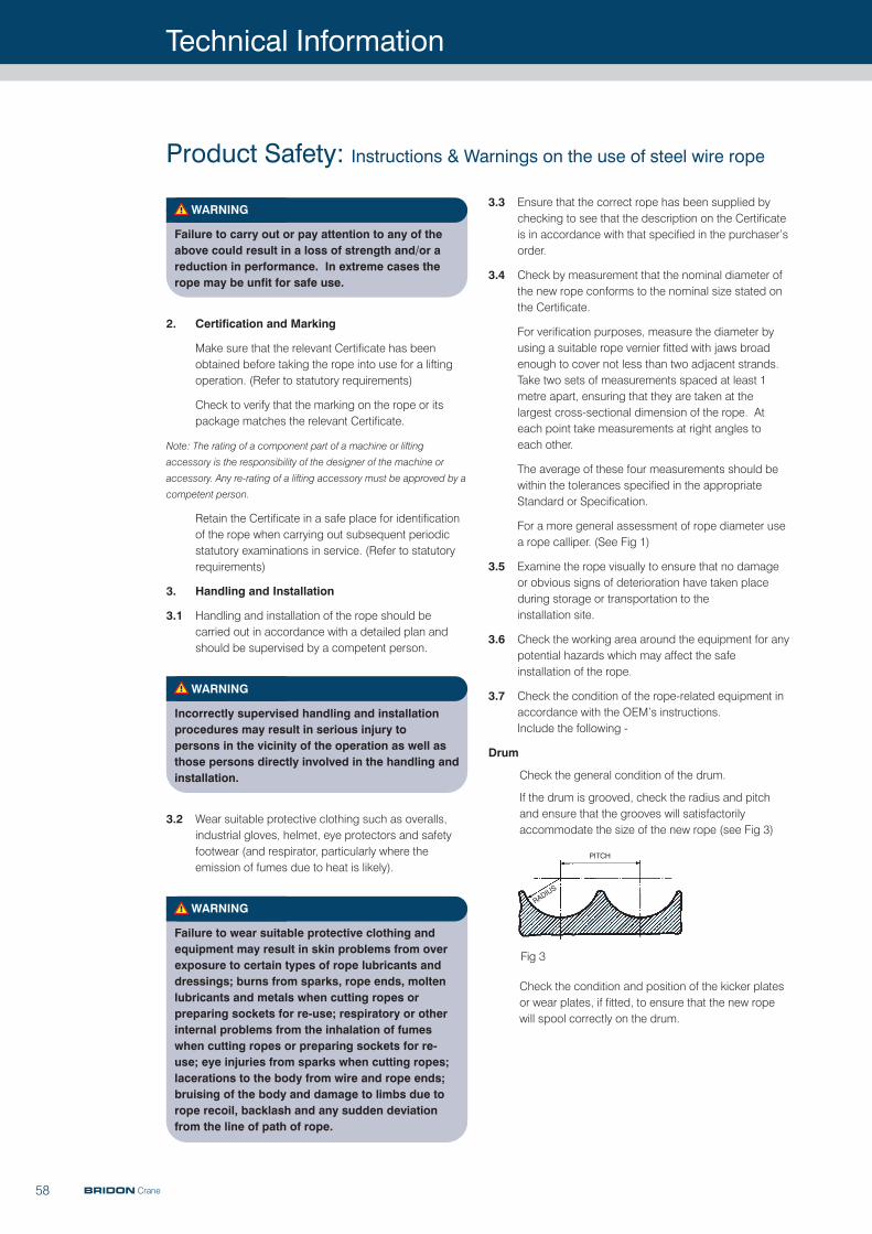
Technical Information
58
WARNING
Failure to carry out or pay attention to any of theabove could result in a loss of strength and/or areduction in performance. In extreme cases therope may be unfit for safe use.
2. Certification and Marking
Make sure that the relevant Certificate has beenobtained before taking the rope into use for a liftingoperation. (Refer to statutory requirements)
Check to verify that the marking on the rope or itspackage matches the relevant Certificate.
Note: The rating of a component part of a machine or lifting
accessory is the responsibility of the designer of the machine or
accessory. Any re-rating of a lifting accessory must be approved by a
competent person.
Retain the Certificate in a safe place for identificationof the rope when carrying out subsequent periodicstatutory examinations in service. (Refer to statutoryrequirements)
3. Handling and Installation
3.1 Handling and installation of the rope should becarried out in accordance with a detailed plan andshould be supervised by a competent person.
WARNING
Incorrectly supervised handling and installationprocedures may result in serious injury to persons in the vicinity of the operation as well asthose persons directly involved in the handling andinstallation.
3.2 Wear suitable protective clothing such as overalls,industrial gloves, helmet, eye protectors and safetyfootwear (and respirator, particularly where theemission of fumes due to heat is likely).
WARNING
Failure to wear suitable protective clothing andequipment may result in skin problems from overexposure to certain types of rope lubricants anddressings; burns from sparks, rope ends, moltenlubricants and metals when cutting ropes orpreparing sockets for re-use; respiratory or otherinternal problems from the inhalation of fumeswhen cutting ropes or preparing sockets for re-use; eye injuries from sparks when cutting ropes;lacerations to the body from wire and rope ends;bruising of the body and damage to limbs due torope recoil, backlash and any sudden deviationfrom the line of path of rope.
3.3 Ensure that the correct rope has been supplied bychecking to see that the description on the Certificateis in accordance with that specified in the purchaser’sorder.
3.4 Check by measurement that the nominal diameter ofthe new rope conforms to the nominal size stated onthe Certificate.
For verification purposes, measure the diameter byusing a suitable rope vernier fitted with jaws broadenough to cover not less than two adjacent strands.Take two sets of measurements spaced at least 1metre apart, ensuring that they are taken at thelargest cross-sectional dimension of the rope. Ateach point take measurements at right angles to each other.
The average of these four measurements should bewithin the tolerances specified in the appropriateStandard or Specification.
For a more general assessment of rope diameter usea rope calliper. (See Fig 1)
3.5 Examine the rope visually to ensure that no damageor obvious signs of deterioration have taken placeduring storage or transportation to the installation site.
3.6 Check the working area around the equipment for anypotential hazards which may affect the safeinstallation of the rope.
3.7 Check the condition of the rope-related equipment inaccordance with the OEM’s instructions. Include the following -
Drum
Check the general condition of the drum.
If the drum is grooved, check the radius and pitchand ensure that the grooves will satisfactorilyaccommodate the size of the new rope (see Fig 3)
Check the condition and position of the kicker platesor wear plates, if fitted, to ensure that the new ropewill spool correctly on the drum.
Product Safety: Instructions & Warnings on the use of steel wire rope
BRIDON Crane
Fig 3
PITCH
RADIU
S
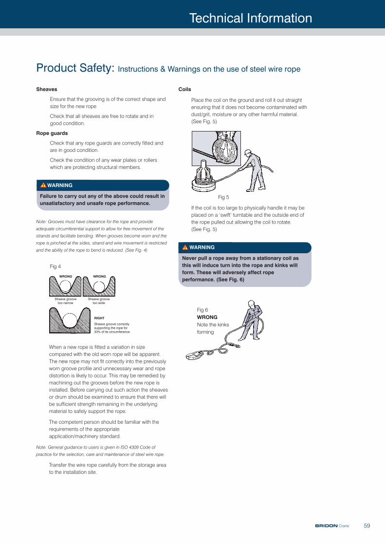
Technical Information
59
Product Safety: Instructions & Warnings on the use of steel wire rope
Sheaves
Ensure that the grooving is of the correct shape andsize for the new rope
Check that all sheaves are free to rotate and in good condition.
Rope guards
Check that any rope guards are correctly fitted andare in good condition.
Check the condition of any wear plates or rollerswhich are protecting structural members.
WARNING
Failure to carry out any of the above could result inunsatisfactory and unsafe rope performance.
Note: Grooves must have clearance for the rope and provide
adequate circumferential support to allow for free movement of the
strands and facilitate bending. When grooves become worn and the
rope is pinched at the sides, strand and wire movement is restricted
and the ability of the rope to bend is reduced. (See Fig. 4)
When a new rope is fitted a variation in sizecompared with the old worn rope will be apparent.The new rope may not fit correctly into the previouslyworn groove profile and unnecessary wear and ropedistortion is likely to occur. This may be remedied bymachining out the grooves before the new rope isinstalled. Before carrying out such action the sheavesor drum should be examined to ensure that there willbe sufficient strength remaining in the underlyingmaterial to safely support the rope.
The competent person should be familiar with therequirements of the appropriateapplication/machinery standard.
Note: General guidance to users is given in ISO 4309 Code of
practice for the selection, care and maintenance of steel wire rope.
Transfer the wire rope carefully from the storage areato the installation site.
Coils
Place the coil on the ground and roll it out straightensuring that it does not become contaminated withdust/grit, moisture or any other harmful material.(See Fig. 5)
If the coil is too large to physically handle it may beplaced on a ‘swift’ turntable and the outside end ofthe rope pulled out allowing the coil to rotate. (See Fig. 5)
WARNING
Never pull a rope away from a stationary coil asthis will induce turn into the rope and kinks willform. These will adversely affect ropeperformance. (See Fig. 6)
Fig 4
Wrong
Sheave groovetoo narrow
Sheave groove too wide
Sheave groove correctlysupporting the rope for33% of its circumference
Wrong
rIgHT
Fig 5
Fig 6
Wrong
Note the kinks
forming
BRIDON Crane
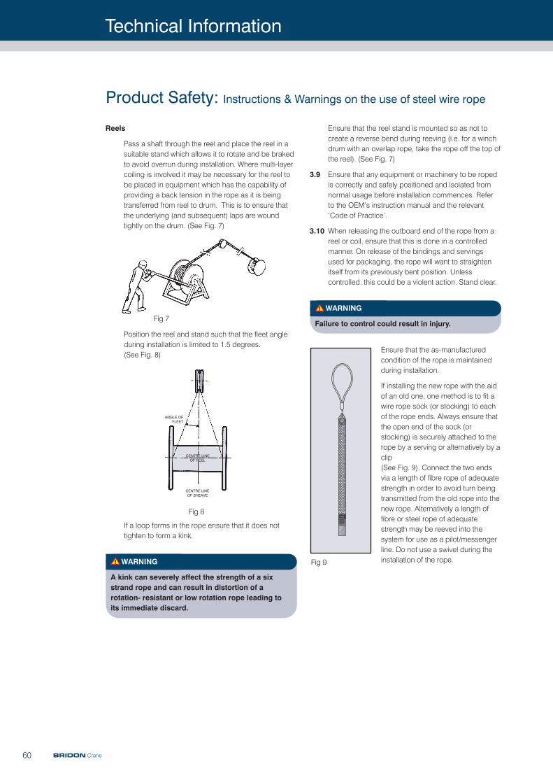
Technical Information
60
Ensure that the reel stand is mounted so as not tocreate a reverse bend during reeving (i.e. for a winchdrum with an overlap rope, take the rope off the top ofthe reel). (See Fig. 7)
3.9 Ensure that any equipment or machinery to be ropedis correctly and safely positioned and isolated fromnormal usage before installation commences. Referto the OEM’s instruction manual and the relevant‘Code of Practice’.
3.10 When releasing the outboard end of the rope from areel or coil, ensure that this is done in a controlledmanner. On release of the bindings and servingsused for packaging, the rope will want to straightenitself from its previously bent position. Unlesscontrolled, this could be a violent action. Stand clear.
WARNING
Failure to control could result in injury.
Ensure that the as-manufacturedcondition of the rope is maintainedduring installation.
If installing the new rope with the aidof an old one, one method is to fit awire rope sock (or stocking) to eachof the rope ends. Always ensure thatthe open end of the sock (orstocking) is securely attached to therope by a serving or alternatively by aclip (See Fig. 9). Connect the two endsvia a length of fibre rope of adequatestrength in order to avoid turn beingtransmitted from the old rope into thenew rope. Alternatively a length offibre or steel rope of adequatestrength may be reeved into thesystem for use as a pilot/messengerline. Do not use a swivel during theinstallation of the rope.
Reels
Pass a shaft through the reel and place the reel in asuitable stand which allows it to rotate and be brakedto avoid overrun during installation. Where multi-layercoiling is involved it may be necessary for the reel tobe placed in equipment which has the capability ofproviding a back tension in the rope as it is beingtransferred from reel to drum. This is to ensure thatthe underlying (and subsequent) laps are woundtightly on the drum. (See Fig. 7)
Position the reel and stand such that the fleet angleduring installation is limited to 1.5 degrees.(See Fig. 8)
If a loop forms in the rope ensure that it does nottighten to form a kink.
WARNING
A kink can severely affect the strength of a sixstrand rope and can result in distortion of arotation- resistant or low rotation rope leading toits immediate discard.
Fig 7
Fig 8
ANGLE OFFLEET
CENTRE LINEOF REEL
CENTRE LINEOF SHEAVE
Fig 9
Product Safety: Instructions & Warnings on the use of steel wire rope
BRIDON Crane
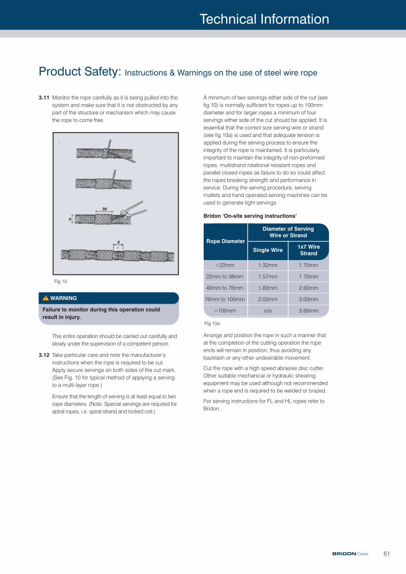
Technical Information
61BRIDON Crane
A minimum of two servings either side of the cut (seefig 10) is normally sufficient for ropes up to 100mmdiameter and for larger ropes a minimum of fourservings either side of the cut should be applied. It isessential that the correct size serving wire or strand(see fig 10a) is used and that adequate tension isapplied during the serving process to ensure theintegrity of the rope is maintained. It is particularlyimportant to maintain the integrity of non-preformedropes, multistrand rotational resistant ropes andparallel closed ropes as failure to do so could affectthe ropes breaking strength and performance inservice. During the serving procedure, servingmallets and hand operated serving machines can beused to generate tight servings.
Bridon ‘On-site serving instructions’
Arrange and position the rope in such a manner thatat the completion of the cutting operation the ropeends will remain in position, thus avoiding anybacklash or any other undesirable movement.
Cut the rope with a high speed abrasive disc cutter.Other suitable mechanical or hydraulic shearingequipment may be used although not recommendedwhen a rope end is required to be welded or brazed.
For serving instructions for FL and HL ropes refer toBridon.
Fig 10
Product Safety: Instructions & Warnings on the use of steel wire rope
3.11 Monitor the rope carefully as it is being pulled into thesystem and make sure that it is not obstructed by anypart of the structure or mechanism which may causethe rope to come free.
WARNING
Failure to monitor during this operation couldresult in injury.
This entire operation should be carried out carefully andslowly under the supervision of a competent person.
3.12 Take particular care and note the manufacturer’sinstructions when the rope is required to be cut.Apply secure servings on both sides of the cut mark.(See Fig. 10 for typical method of applying a servingto a multi-layer rope.)
Ensure that the length of serving is at least equal to tworope diameters. (Note: Special servings are required forspiral ropes, i.e. spiral strand and locked coil.)
<22mm
22mm to 38mm
40mm to 76mm
76mm to 100mm
>100mm
1.32mm
1.57mm
1.83mm
2.03mm
n/a
1.70mm
1.70mm
2.60mm
3.00mm
3.60mm
Rope Diameter
Diameter of Serving Wire or Strand
Single Wire 1x7 WireStrand
Fig 10a
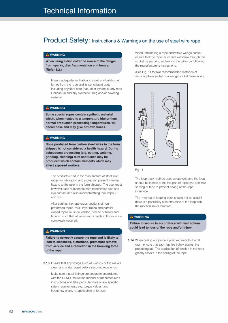
Technical Information
62
When terminating a rope end with a wedge socket,ensure that the rope tail cannot withdraw through thesocket by securing a clamp to the tail or by followingthe manufacturer’s instructions.
(See Fig. 11 for two recommended methods ofsecuring the rope tail of a wedge socket termination).
The loop back method uses a rope grip and the loopshould be lashed to the live part of rope by a soft wireserving or tape to prevent flexing of the rope in service.
The method of looping back should not be used ifthere is a possibility of interference of the loop withthe mechanism or structure.
WARNING
Failure to secure in accordance with instructionscould lead to loss of the rope and/or injury.
3.14 When coiling a rope on a plain (or smooth) barreldrum ensure that each lap lies tightly against thepreceding lap. The application of tension in the ropegreatly assists in the coiling of the rope.
WARNING
When using a disc cutter be aware of the dangerfrom sparks, disc fragmentation and fumes.(Refer 3.2.)
Ensure adequate ventilation to avoid any build-up offumes from the rope and its constituent partsincluding any fibre core (natural or synthetic) any ropelubricant(s) and any synthetic filling and/or coveringmaterial.
WARNING
Some special ropes contain synthetic materialwhich, when heated to a temperature higher thannormal production processing temperatures, willdecompose and may give off toxic fumes.
WARNING
Rope produced from carbon steel wires in the formshipped is not considered a health hazard. Duringsubsequent processing (e.g. cutting, welding,grinding, cleaning) dust and fumes may beproduced which contain elements which mayaffect exposed workers.
The products used in the manufacture of steel wireropes for lubrication and protection present minimalhazard to the user in the form shipped. The user musthowever, take reasonable care to minimise skin andeye contact and also avoid breathing their vapour and mist.
After cutting, the rope cross-sections of non-preformed ropes, multi-layer ropes and parallelclosed ropes must be welded, brazed or fused andtapered such that all wires and strands in the rope arecompletely secured.
WARNING
Failure to correctly secure the rope end is likely tolead to slackness, distortions, premature removalfrom service and a reduction in the breaking forceof the rope.
3.13 Ensure that any fittings such as clamps or fixtures areclean and undamaged before securing rope ends.
Make sure that all fittings are secure in accordancewith the OEM’s instruction manual or manufacturer’sinstructions and take particular note of any specificsafety requirements e.g. torque values (andfrequency of any re-application of torque).
Fig 11
Product Safety: Instructions & Warnings on the use of steel wire rope
BRIDON Crane
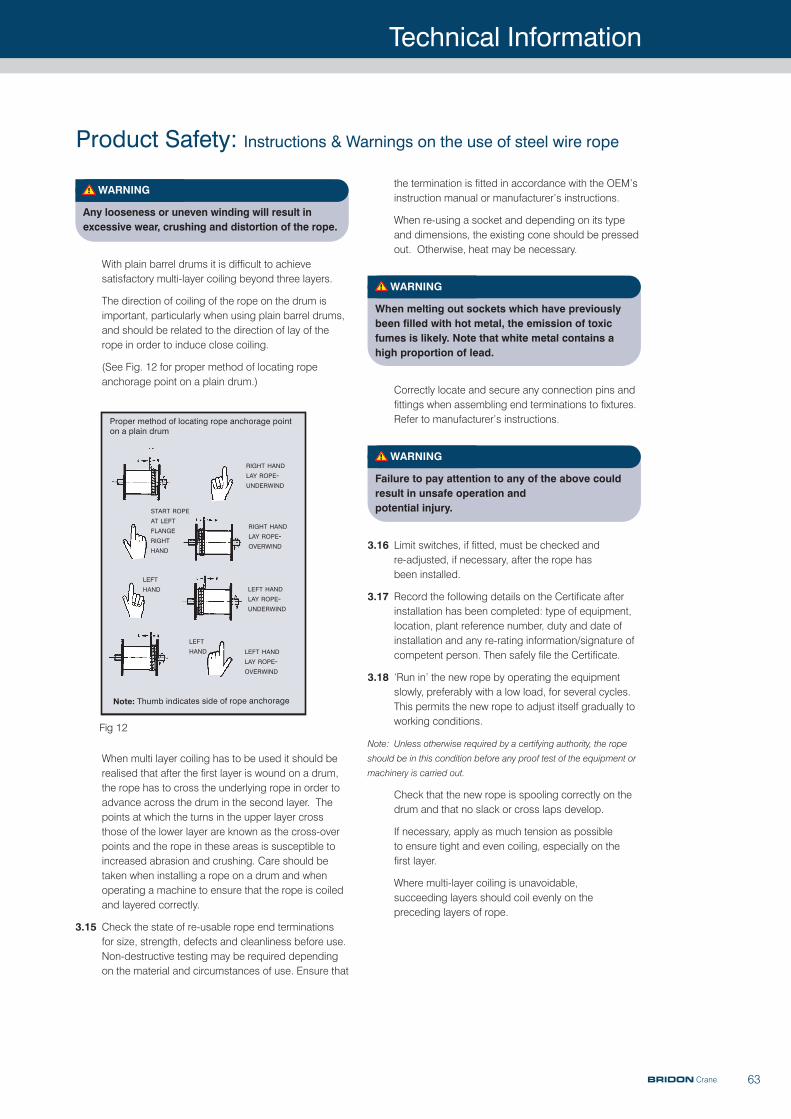
Technical Information
63
the termination is fitted in accordance with the OEM’sinstruction manual or manufacturer’s instructions.
When re-using a socket and depending on its typeand dimensions, the existing cone should be pressedout. Otherwise, heat may be necessary.
WARNING
When melting out sockets which have previouslybeen filled with hot metal, the emission of toxicfumes is likely. Note that white metal contains ahigh proportion of lead.
Correctly locate and secure any connection pins andfittings when assembling end terminations to fixtures.Refer to manufacturer’s instructions.
WARNING
Failure to pay attention to any of the above couldresult in unsafe operation and potential injury.
3.16 Limit switches, if fitted, must be checked and re-adjusted, if necessary, after the rope has been installed.
3.17 Record the following details on the Certificate afterinstallation has been completed: type of equipment,location, plant reference number, duty and date ofinstallation and any re-rating information/signature ofcompetent person. Then safely file the Certificate.
3.18 ‘Run in’ the new rope by operating the equipmentslowly, preferably with a low load, for several cycles.This permits the new rope to adjust itself gradually toworking conditions.
Note: Unless otherwise required by a certifying authority, the rope
should be in this condition before any proof test of the equipment or
machinery is carried out.
Check that the new rope is spooling correctly on thedrum and that no slack or cross laps develop.
If necessary, apply as much tension as possible to ensure tight and even coiling, especially on the first layer.
Where multi-layer coiling is unavoidable, succeeding layers should coil evenly on thepreceding layers of rope.
WARNING
Any looseness or uneven winding will result inexcessive wear, crushing and distortion of the rope.
With plain barrel drums it is difficult to achievesatisfactory multi-layer coiling beyond three layers.
The direction of coiling of the rope on the drum isimportant, particularly when using plain barrel drums,and should be related to the direction of lay of therope in order to induce close coiling.
(See Fig. 12 for proper method of locating ropeanchorage point on a plain drum.)
When multi layer coiling has to be used it should berealised that after the first layer is wound on a drum,the rope has to cross the underlying rope in order toadvance across the drum in the second layer. Thepoints at which the turns in the upper layer crossthose of the lower layer are known as the cross-overpoints and the rope in these areas is susceptible toincreased abrasion and crushing. Care should betaken when installing a rope on a drum and whenoperating a machine to ensure that the rope is coiledand layered correctly.
3.15 Check the state of re-usable rope end terminationsfor size, strength, defects and cleanliness before use.Non-destructive testing may be required dependingon the material and circumstances of use. Ensure that
Proper method of locating rope anchorage pointon a plain drum
RIGHT HAND
LAY ROPE-UNDERWIND
RIGHT HAND
LAY ROPE-OVERWIND
LEFT HAND
LAY ROPE-UNDERWIND
LEFT HAND
LAY ROPE-OVERWIND
LEFT
HAND
LEFT
HAND
START ROPE
AT LEFT
FLANGE
RIGHT
HAND
note: Thumb indicates side of rope anchorage
Fig 12
Product Safety: Instructions & Warnings on the use of steel wire rope
BRIDON Crane
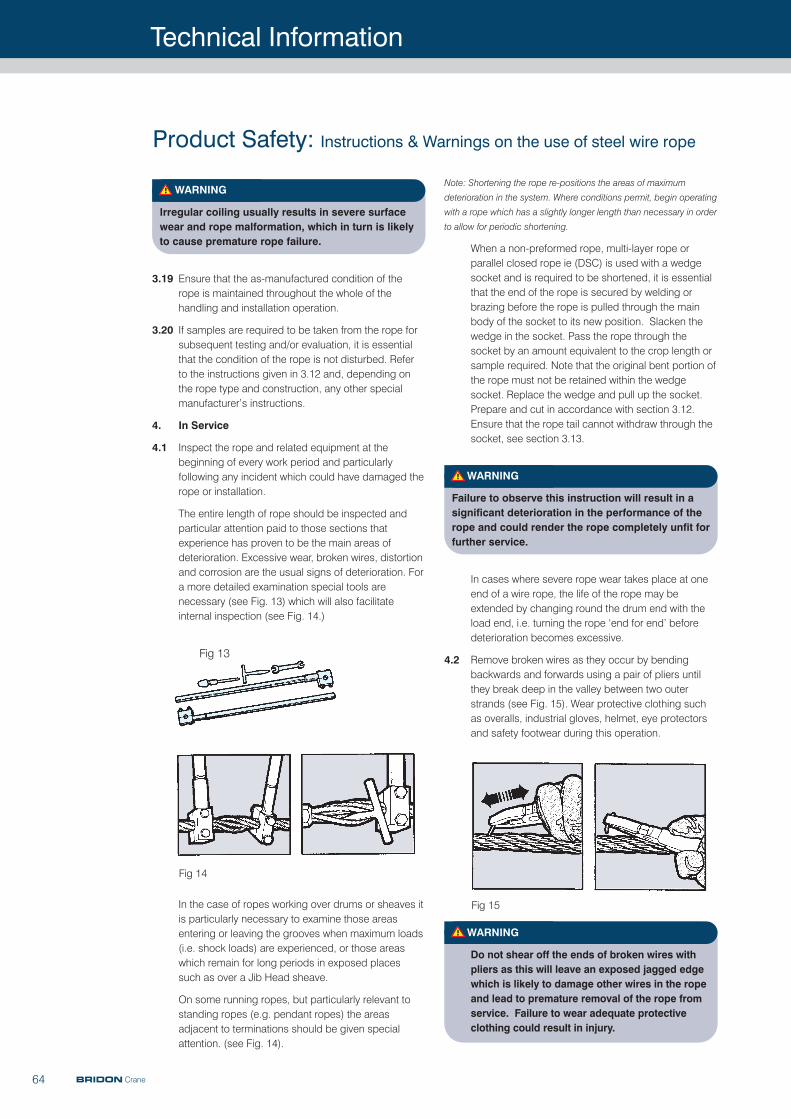
Technical Information
64
Note: Shortening the rope re-positions the areas of maximum
deterioration in the system. Where conditions permit, begin operating
with a rope which has a slightly longer length than necessary in order
to allow for periodic shortening.
When a non-preformed rope, multi-layer rope orparallel closed rope ie (DSC) is used with a wedgesocket and is required to be shortened, it is essentialthat the end of the rope is secured by welding orbrazing before the rope is pulled through the mainbody of the socket to its new position. Slacken thewedge in the socket. Pass the rope through thesocket by an amount equivalent to the crop length orsample required. Note that the original bent portion ofthe rope must not be retained within the wedgesocket. Replace the wedge and pull up the socket.Prepare and cut in accordance with section 3.12.Ensure that the rope tail cannot withdraw through thesocket, see section 3.13.
WARNING
Failure to observe this instruction will result in asignificant deterioration in the performance of therope and could render the rope completely unfit forfurther service.
In cases where severe rope wear takes place at oneend of a wire rope, the life of the rope may beextended by changing round the drum end with theload end, i.e. turning the rope ‘end for end’ beforedeterioration becomes excessive.
4.2 Remove broken wires as they occur by bendingbackwards and forwards using a pair of pliers untilthey break deep in the valley between two outerstrands (see Fig. 15). Wear protective clothing suchas overalls, industrial gloves, helmet, eye protectorsand safety footwear during this operation.
WARNING
Do not shear off the ends of broken wires withpliers as this will leave an exposed jagged edgewhich is likely to damage other wires in the ropeand lead to premature removal of the rope fromservice. Failure to wear adequate protectiveclothing could result in injury.
WARNING
Irregular coiling usually results in severe surfacewear and rope malformation, which in turn is likelyto cause premature rope failure.
3.19 Ensure that the as-manufactured condition of therope is maintained throughout the whole of thehandling and installation operation.
3.20 If samples are required to be taken from the rope forsubsequent testing and/or evaluation, it is essentialthat the condition of the rope is not disturbed. Referto the instructions given in 3.12 and, depending onthe rope type and construction, any other specialmanufacturer’s instructions.
4. In Service
4.1 Inspect the rope and related equipment at thebeginning of every work period and particularlyfollowing any incident which could have damaged therope or installation.
The entire length of rope should be inspected andparticular attention paid to those sections thatexperience has proven to be the main areas ofdeterioration. Excessive wear, broken wires, distortionand corrosion are the usual signs of deterioration. Fora more detailed examination special tools arenecessary (see Fig. 13) which will also facilitateinternal inspection (see Fig. 14.)
In the case of ropes working over drums or sheaves itis particularly necessary to examine those areasentering or leaving the grooves when maximum loads(i.e. shock loads) are experienced, or those areaswhich remain for long periods in exposed placessuch as over a Jib Head sheave.
On some running ropes, but particularly relevant tostanding ropes (e.g. pendant ropes) the areasadjacent to terminations should be given specialattention. (see Fig. 14).
Fig 13
Fig 14
Fig 15
Product Safety: Instructions & Warnings on the use of steel wire rope
BRIDON Crane
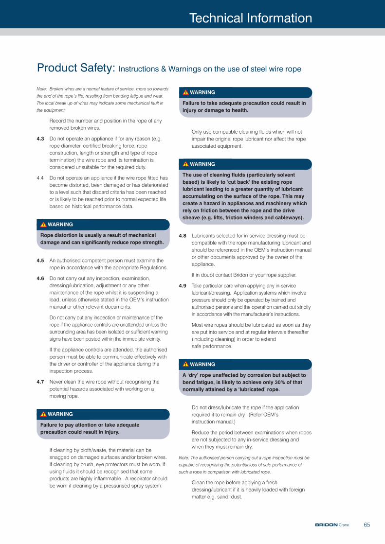
Technical Information
65
WARNING
Failure to take adequate precaution could result ininjury or damage to health.
Only use compatible cleaning fluids which will notimpair the original rope lubricant nor affect the ropeassociated equipment.
WARNING
The use of cleaning fluids (particularly solventbased) is likely to ‘cut back’ the existing ropelubricant leading to a greater quantity of lubricantaccumulating on the surface of the rope. This maycreate a hazard in appliances and machinery whichrely on friction between the rope and the drivesheave (e.g. lifts, friction winders and cableways).
4.8 Lubricants selected for in-service dressing must becompatible with the rope manufacturing lubricant andshould be referenced in the OEM’s instruction manualor other documents approved by the owner of theappliance.
If in doubt contact Bridon or your rope supplier.
4.9 Take particular care when applying any in-servicelubricant/dressing. Application systems which involvepressure should only be operated by trained andauthorised persons and the operation carried out strictlyin accordance with the manufacturer’s instructions.
Most wire ropes should be lubricated as soon as theyare put into service and at regular intervals thereafter(including cleaning) in order to extend safe performance.
WARNING
A ‘dry’ rope unaffected by corrosion but subject tobend fatigue, is likely to achieve only 30% of thatnormally attained by a ‘lubricated’ rope.
Do not dress/lubricate the rope if the applicationrequired it to remain dry. (Refer OEM’s instruction manual.)
Reduce the period between examinations when ropesare not subjected to any in-service dressing andwhen they must remain dry.
Note: The authorised person carrying out a rope inspection must be
capable of recognising the potential loss of safe performance of
such a rope in comparison with lubricated rope.
Clean the rope before applying a freshdressing/lubricant if it is heavily loaded with foreignmatter e.g. sand, dust.
Note: Broken wires are a normal feature of service, more so towards
the end of the rope’s life, resulting from bending fatigue and wear.
The local break up of wires may indicate some mechanical fault in
the equipment.
Record the number and position in the rope of anyremoved broken wires.
4.3 Do not operate an appliance if for any reason (e.g.rope diameter, certified breaking force, ropeconstruction, length or strength and type of ropetermination) the wire rope and its termination isconsidered unsuitable for the required duty.
4.4 Do not operate an appliance if the wire rope fitted hasbecome distorted, been damaged or has deterioratedto a level such that discard criteria has been reachedor is likely to be reached prior to normal expected lifebased on historical performance data.
WARNING
Rope distortion is usually a result of mechanicaldamage and can significantly reduce rope stren gth.
4.5 An authorised competent person must examine therope in accordance with the appropriate Regulations.
4.6 Do not carry out any inspection, examination,dressing/lubrication, adjustment or any othermaintenance of the rope whilst it is suspending aload, unless otherwise stated in the OEM’s instructionmanual or other relevant documents.
Do not carry out any inspection or maintenance of therope if the appliance controls are unattended unless thesurrounding area has been isolated or sufficient warningsigns have been posted within the immediate vicinity.
If the appliance controls are attended, the authorisedperson must be able to communicate effectively withthe driver or controller of the appliance during theinspection process.
4.7 Never clean the wire rope without recognising thepotential hazards associated with working on amoving rope.
WARNING
Failure to pay attention or take adequateprecaution could result in injury.
If cleaning by cloth/waste, the material can besnagged on damaged surfaces and/or broken wires.If cleaning by brush, eye protectors must be worn. Ifusing fluids it should be recognised that someproducts are highly inflammable. A respirator shouldbe worn if cleaning by a pressurised spray system.
Product Safety: Instructions & Warnings on the use of steel wire rope
BRIDON Crane
Technical Information
66
Ensure that the sample is kept straight throughout thewhole procedure and ensure that the minimumsample length is 4 metres for ropes up to andincluding 76mm diameter and 8 metres for largerdiameter ropes.
The rope should be cut with a high speed abrasivedisc cutter or an oxyacetylene torch. Weld the ropeends of the sample as described in section 3.12, afterwhich the clamp or grip can be removed.
The identification of the rope must be established andthe sample suitably marked and packed. It isrecommended that the 3 metre sample is retainedstraight and secured to a wood batten fortransportation. For a 12 metre sample, coil to adiameter as large as practically possible and neverless than 2 metres.
Note: Samples taken for destruction testing are required to be
terminated in accordance with a recognised resin socketing
standard (e.g. BS EN 13411-4).
WARNING
Failure to comply with these procedures will result inmeasured breaking force values which are not trulyrepresentative of the actual strength of the rope.
5. Wire Rope Discard
5.1 Discard the wire rope in accordance with currentRegulations and in accordance with the OEM’sinstruction manual.
Note: The authorised competent person should also be familiar with
the latest versions of International Standard ISO 4309 ‘Cranes
- wire ropes - Code of practice for examination and discard’
and B.S. 6570 ‘ The selection, care and maintenance of steel
wire ropes’ which provide greater detail than that given in the
relevant Regulations. Other standards and instructions
covering rope discard may also be applicable. In the case of
synthetic sheaves (or synthetic linings) refer to the OEM’s
instruction manual or contact the sheave (or lining)
manufacturer for specific discard criteria.
5.2 If a wire rope is removed from service at a level ofperformance substantially different to historicallyestablished performance data and without anyobvious reason(s), contact Bridon or Bridon’sdistributor for further guidance.
5.3 Only qualified and experienced personnel, taking theappropriate safety precautions and wearing theappropriate protective clothing, should beresponsible for removing the wire rope.
WARNING
Take particular care when removing ropes withmechanical damage as they may fail abruptlyduring the change-out procedure.
4.10 The authorised person responsible for carrying outwire rope maintenance must ensure that the ends ofthe rope are secure. At the drum end this will involvechecking the integrity of the anchorage and ensuringthat there are at least two and a half dead laps tightlycoiled. At the outboard end the integrity of thetermination must be checked to ensure that it is inaccordance with the OEM’s manual or otherdocuments approved by the owner of the appliance.
Adjust the lengths of ropes in multi-rope systems inorder that equal forces (within approved limits) are evident.
If a wire rope needs cutting refer to 3.12.
When securing rope ends refer to 3.13.
When re-usable end terminations are used refer to 3.15.
When re-connecting any end terminations to fixturesrefer to 3.15.
4.11
WARNING
Damage to, or removal of component parts(mechanical or structural) caused by abnormalcontact with wire rope can be hazardous to thesafety of the appliance and/or the performanceof the rope (e.g. damage to the drum grooving,such that coiling is erratic and/or the rope is‘pulled down’ into underlying layers, whichmight cause a dangerous condition or,alternatively, cause localised rope damage at‘cross-over’ positions, which might thenradically affect performance; loss/removal ofwear plates protecting the structure leading tomajor structural damage by cutting and/or failureof the wire rope due to mechanical severance).
4.12 Following any periodic statutory examination orroutine or special inspection where any correctiveaction is taken the Certificate should be updated anda record made of the defects found, the extent of thechanges and the condition of the rope.
4.13 Apply the following procedures for the selection andpreparation of samples, from new and used lengthsof rope, for the purpose of examination and testing todestruction.
Check that the rope end, from which the sample willbe taken, is secured by welding or brazing. If not,select the sample length further away from the ropeend and prepare new servings (see 3.12).
Handle the rope in accordance with the instructionsgiven in section 3. Serve the rope, using the buriedwire technique (see Fig. 10) and apply a rope clampor grip as close to the cut mark as practicallypossible. Do not use solder to secure the servings.
Product Safety: Instructions & Warnings on the use of steel wire rope
BRIDON Crane
Technical Information
67
WARNING
Wire rope which bends around sheaves, rollers ordrums will deteriorate through ‘bending fatigue’.Reverse bending and high speed will acceleratethe process. Therefore, under such conditionsselect a rope with high bending fatigue resistance.Refer to Product Data Information, and if in doubtask for advice.
6.3 Abrasion
Wire rope which is subject to abrasion will becomeprogressively weaker as a result of:
Externally - dragging it through overburden, sand orother abrasive materials and passing around asheave, roller or drum.
Internally - being loaded or bent.
WARNING
Abrasion weakens the rope by removing metalfrom both the inner and outer wires. Therefore, a rope with large outer wires should normally be selected.
6.4 Vibration
Vibration in wire rope will cause deterioration. Thismay become apparent in the form of wire fractureswhere the vibration is absorbed.
WARNING
These fractures may be internal only and will notbe visually identified.
6.5 Distortion
Wire rope can be distorted due to high pressureagainst a sheave, improperly sized grooves or as aresult of multi-layer coiling on a drum.
Rope with a steel core is more resistant to crushingand distortion.
6.6 Corrosion
Rope with a large number of small wires is moresusceptible to corrosion than rope with a smallnumber of large wires. Therefore, if corrosion isexpected to have a significant effect on ropeperformance select a galvanised rope with as largean outer wire size as possible bearing in mind theother conditions (e.g. bending and abrasion) underwhich the rope will be operating.
Take the utmost care when removing ‘exhausted/failed’ropes from drums and sheaves as they may be grosslydistorted, lively and tightly coiled.
WARNING
Failure to take adequate precautions could resultin injury.
5.4 Store discarded rope in a safe and secure location orcompound and ensure that it is suitably marked toidentify it as rope which has been removed fromservice and not to be used again.
WARNING
Discarded rope can be a danger (e.g. protrudingbroken wires, excessive grease/lubricant and ropemass) to personnel and equipment if not handledcorrectly and safely during disposal.
5.5 Record the date and reason for discard on theCertificate before filing for future reference.
5.6 Pay attention to any Regulations affecting the safedisposal of steel wire rope.
6. Rope Selection Criteria
Ensure that the correct type of wire rope is selectedfor the equipment by referring to the OEM’sinstruction manual or other relevant documents. If indoubt contact Bridon or Bridon’s distributor for guidance.
6.1 Rope Strength
If necessary, refer to the appropriate Regulationsand/or application standards and calculate themaximum force to which the rope will be subjected.
The calculation may take into account the mass to belifted or moved, any shock loading, effects of highspeed, acceleration, any sudden starts or stops,frequency of operation and sheave bearing friction.
By applying the relevant coefficient of utilisation(safety factor) and, where applicable, the efficiency ofthe rope termination, the required minimum breakingload or force of the rope will be determined, thevalues of which are available from the relevantNational, European or International standards or fromspecific Product Data literature. If in doubt ask for advice from Bridon or Bridon’s distributor.
6.2 Bending fatigue
The size and number of sheaves in the system willinfluence the performance of the rope.
Product Safety: Instructions & Warnings on the use of steel wire rope
BRIDON Crane
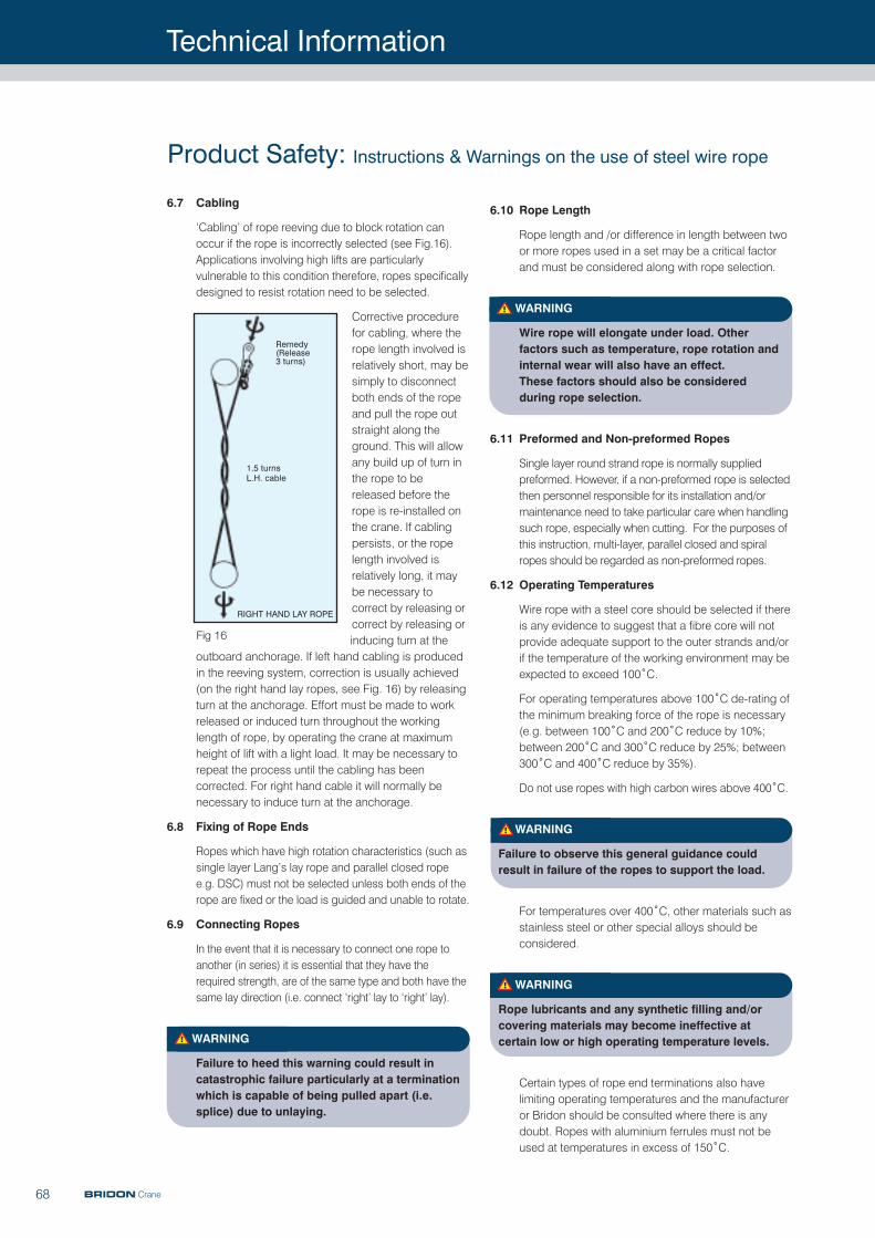
Technical Information
68
6.10 Rope Length
Rope length and /or difference in length between twoor more ropes used in a set may be a critical factorand must be considered along with rope selection.
WARNING
Wire rope will elongate under load. Other factors such as temperature, rope rotation andinternal wear will also have an effect. These factors should also be considered during rope selection.
6.11 Preformed and Non-preformed Ropes
Single layer round strand rope is normally suppliedpreformed. However, if a non-preformed rope is selectedthen personnel responsible for its installation and/ormaintenance need to take particular care when handlingsuch rope, especially when cutting. For the purposes ofthis instruction, multi-layer, parallel closed and spiralropes should be regarded as non-preformed ropes.
6.12 Operating Temperatures
Wire rope with a steel core should be selected if thereis any evidence to suggest that a fibre core will notprovide adequate support to the outer strands and/orif the temperature of the working environment may beexpected to exceed 100˚C.
For operating temperatures above 100˚C de-rating ofthe minimum breaking force of the rope is necessary(e.g. between 100˚C and 200˚C reduce by 10%;between 200˚C and 300˚C reduce by 25%; between300˚C and 400˚C reduce by 35%).
Do not use ropes with high carbon wires above 400˚C.
WARNING
Failure to observe this general guidance couldresult in failure of the ropes to support the load.
For temperatures over 400˚C, other materials such asstainless steel or other special alloys should beconsidered.
WARNING
Rope lubricants and any synthetic filling and/orcovering materials may become ineffective atcertain low or high operating temperature levels.
Certain types of rope end terminations also havelimiting operating temperatures and the manufactureror Bridon should be consulted where there is anydoubt. Ropes with aluminium ferrules must not beused at temperatures in excess of 150˚C.
6.7 Cabling
‘Cabling’ of rope reeving due to block rotation canoccur if the rope is incorrectly selected (see Fig.16).Applications involving high lifts are particularlyvulnerable to this condition therefore, ropes specificallydesigned to resist rotation need to be selected.
Corrective procedurefor cabling, where therope length involved isrelatively short, may besimply to disconnectboth ends of the ropeand pull the rope outstraight along theground. This will allowany build up of turn inthe rope to bereleased before therope is re-installed onthe crane. If cablingpersists, or the ropelength involved isrelatively long, it maybe necessary tocorrect by releasing orcorrect by releasing orinducing turn at the
outboard anchorage. If left hand cabling is producedin the reeving system, correction is usually achieved(on the right hand lay ropes, see Fig. 16) by releasingturn at the anchorage. Effort must be made to workreleased or induced turn throughout the workinglength of rope, by operating the crane at maximumheight of lift with a light load. It may be necessary torepeat the process until the cabling has beencorrected. For right hand cable it will normally benecessary to induce turn at the anchorage.
6.8 Fixing of Rope Ends
Ropes which have high rotation characteristics (such assingle layer Lang’s lay rope and parallel closed ropee.g. DSC) must not be selected unless both ends of therope are fixed or the load is guided and unable to rotate.
6.9 Connecting Ropes
In the event that it is necessary to connect one rope toanother (in series) it is essential that they have therequired strength, are of the same type and both have thesame lay direction (i.e. connect ‘right’ lay to ‘right’ lay).
WARNING
Failure to heed this warning could result incatastrophic failure particularly at a terminationwhich is capable of being pulled apart (i.e.splice) due to unlaying.
Product Safety: Instructions & Warnings on the use of steel wire rope
BRIDON Crane
Remedy(Release3 turns)
1.5 turnsL.H. cable
RIGHT HAND LAY ROPE
Fig 16
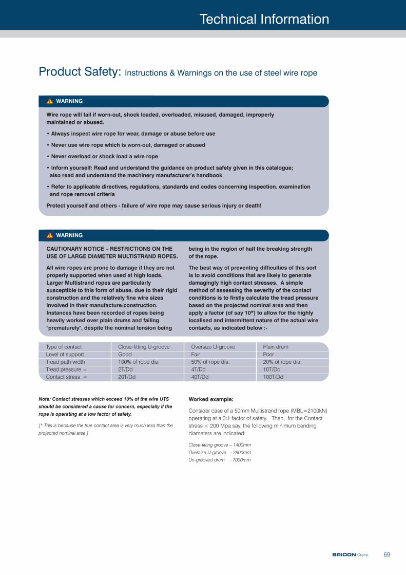
Technical Information
69
WARNING
CAUTIONARY NOTICE – RESTRICTIONS ON THEUSE OF LARGE DIAMETER MULTISTRAND ROPES.
All wire ropes are prone to damage if they are notproperly supported when used at high loads.Larger Multistrand ropes are particularlysusceptible to this form of abuse, due to their rigidconstruction and the relatively fine wire sizesinvolved in their manufacture/construction.Instances have been recorded of ropes beingheavily worked over plain drums and failing"prematurely", despite the nominal tension being
Type of contact Close-fitting U-groove Oversize U-groove Plain drumLevel of support Good Fair PoorTread path width 100% of rope dia. 50% of rope dia. 20% of rope dia.Tread pressure = 2T/Dd 4T/Dd 10T/DdContact stress = 20T/Dd 40T/Dd 100T/Dd
being in the region of half the breaking strength of the rope.
The best way of preventing difficulties of this sortis to avoid conditions that are likely to generatedamagingly high contact stresses. A simplemethod of assessing the severity of the contactconditions is to firstly calculate the tread pressurebased on the projected nominal area and thenapply a factor (of say 10*) to allow for the highlylocalised and intermittent nature of the actual wirecontacts, as indicated below :-
WARNING
Wire rope will fail if worn-out, shock loaded, overloaded, misused, damaged, improperly maintained or abused.
• Always inspect wire rope for wear, damage or abuse before use
• Never use wire rope which is worn-out, damaged or abused
• Never overload or shock load a wire rope
• Inform yourself: Read and understand the guidance on product safety given in this catalogue; also read and understand the machinery manufacturer’s handbook
• Refer to applicable directives, regulations, standards and codes concerning inspection, examination and rope removal criteria
Protect yourself and others - failure of wire rope may cause serious injury or death!
Note: Contact stresses which exceed 10% of the wire UTS
should be considered a cause for concern, especially if the
rope is operating at a low factor of safety.
[* This is because the true contact area is very much less than the
projected nominal area.]
Worked example:
Consider case of a 50mm Multistrand rope (MBL=2100kN)operating at a 3:1 factor of safety. Then, for the Contactstress < 200 Mpa say, the following minimum bendingdiameters are indicated:
Close-fitting groove – 1400mm
Oversize U-groove - 2800mm
Un-grooved drum - 7000mm
Product Safety: Instructions & Warnings on the use of steel wire rope
BRIDON Crane
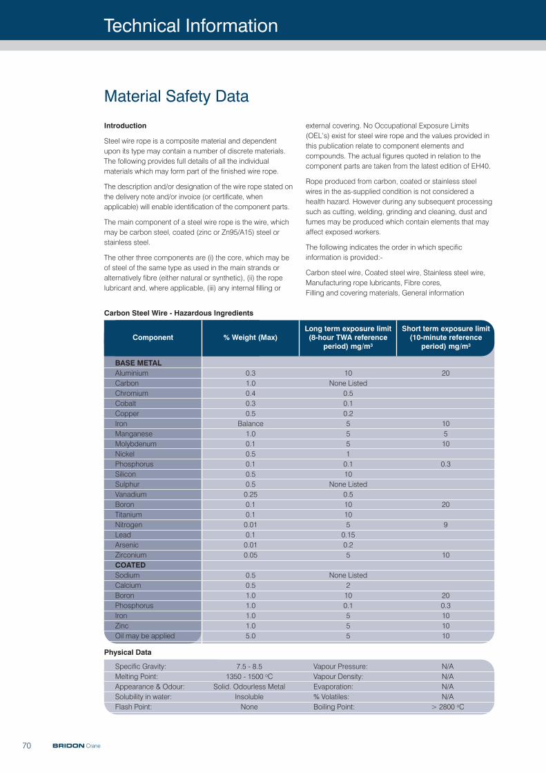
Technical Information
70
external covering. No Occupational Exposure Limits(OEL’s) exist for steel wire rope and the values provided inthis publication relate to component elements andcompounds. The actual figures quoted in relation to thecomponent parts are taken from the latest edition of EH40.
Rope produced from carbon, coated or stainless steelwires in the as-supplied condition is not considered ahealth hazard. However during any subsequent processingsuch as cutting, welding, grinding and cleaning, dust andfumes may be produced which contain elements that mayaffect exposed workers.
The following indicates the order in which specificinformation is provided:-
Carbon steel wire, Coated steel wire, Stainless steel wire,Manufacturing rope lubricants, Fibre cores, Filling and covering materials, General information
Introduction
Steel wire rope is a composite material and dependentupon its type may contain a number of discrete materials.The following provides full details of all the individualmaterials which may form part of the finished wire rope.
The description and/or designation of the wire rope stated onthe delivery note and/or invoice (or certificate, whenapplicable) will enable identification of the component parts.
The main component of a steel wire rope is the wire, whichmay be carbon steel, coated (zinc or Zn95/A15) steel orstainless steel.
The other three components are (i) the core, which may beof steel of the same type as used in the main strands oralternatively fibre (either natural or synthetic), (ii) the ropelubricant and, where applicable, (iii) any internal filling or
Material Safety Data
BASE METALAluminiumCarbonChromiumCobaltCopperIronManganeseMolybdenumNickelPhosphorusSiliconSulphurVanadiumBoronTitaniumNitrogenLeadArsenicZirconiumCOATEDSodiumCalciumBoronPhosphorusIronZincOil may be applied
0.31.00.40.30.5
Balance1.00.10.50.10.50.50.250.10.10.010.10.010.05
0.50.51.01.01.01.05.0
10None Listed
0.50.10.255510.110
None Listed0.5101050.150.25
None Listed2100.1555
20
10510
0.3
20
9
10
200.3101010
Specific Gravity: 7.5 - 8.5Melting Point: 1350 - 1500 oCAppearance & Odour: Solid. Odourless MetalSolubility in water: InsolubleFlash Point: None
Vapour Pressure: N/AVapour Density: N/AEvaporation: N/A% Volatiles: N/ABoiling Point: > 2800 oC
Component % Weight (Max)Long term exposure limit(8-hour TWA reference
period) mg/m3
Short term exposure limit(10-minute reference
period) mg/m3
Carbon Steel Wire - Hazardous Ingredients
Physical Data
BRIDON Crane
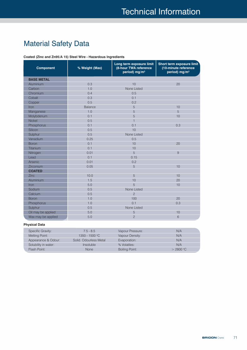
Technical Information
71
Material Safety Data
BASE METALAluminiumCarbonChromiumCobaltCopperIronManganeseMolybdenumNickelPhosphorusSiliconSulphurVanadiumBoronTitaniumNitrogenLeadArsenicZirconiumCOATEDZincAluminiumIronSodiumCalciumBoronPhosphorusSulphurOil may be appliedWax may be applied
0.31.00.40.30.5
Balance1.00.10.50.10.50.50.250.10.10.010.10.010.05
10.01.55.00.50.51.01.00.55.05.0
10None Listed
0.50.10.255510.110
None Listed0.5101050.150.25
5105
None Listed21000.1
None Listed52
20
10510
0.3
20
9
10
102010
200.3
106
Specific Gravity: 7.5 - 8.5Melting Point: 1350 - 1500 oCAppearance & Odour: Solid. Odourless MetalSolubility in water: InsolubleFlash Point: None
Vapour Pressure: N/AVapour Density: N/AEvaporation: N/A% Volatiles: N/ABoiling Point: > 2800 oC
Component % Weight (Max)Long term exposure limit(8-hour TWA reference
period) mg/m3
Short term exposure limit(10-minute reference
period) mg/m3
Coated (Zinc and Zn95/A 15) Steel Wire - Hazardous Ingredients
Physical Data
BRIDON Crane
Technical Information
72
The worker should:1) use oil impermeable gloves, or if not available, suitable
oil repellent type barrier creams,2) avoid unnecessary contact with oil using protective clothing,3) obtain first aid treatment for any injury, however slight,4) wash hands thoroughly before meals, before using the
toilet and after work,5) use conditioning creams after washing, where provided.
The worker should not:1) put oily rags or tools into pockets, especially trousers,2) use dirty or spoiled rags for wiping oil from the skin,3) wear oil soaked clothing,4) use solvents such as parafin, petrol etc., to remove oil
from the skin.
Concentrations of oil mists, fumes and vapours in the workingatmosphere must be kept as low as is reasonably practicable.Levels quoted in the current edition of HSE Guidance NoteEH40 ‘Occupational Exposure Limits’ must not be exceeded.
Health Hazards
Inhalation of oil mists or fumes from heated rope lubricantsin high concentrations may result in dizziness, headache,respiratory irritation or unconsciousness. Eye contact mayproduce mild transient irritation to some users.
Fumes from heated rope lubricants in high concentrationsmay cause eye irritation.
If heated rope lubricants contacts skin, severe burns may result.
Prolonged or repeated skin contact may cause irritation,dermatitis or more serious skin disorders.
Fibre Cores
Being in the centre of a steel wire rope, the materials(natural or synthetic) from which fibre cores are produceddo not present a health hazard during normal ropehandling. Even when the outer core strands are removed(for example when the rope is required to be socketed) thecore materials present virtually no hazard to the users,except, maybe, in the case of a used rope where, in theabsence of any service dressing or as a result of heavyworking causing internal abrasive wear of the core, the coremay have decomposed into a fibre dust which might beinhaled, although this is considered extremely unlikely.
The principal area of hazard is through the inhalation offumes generated by heat, for example when the rope isbeing cut by a disc cutter.
Manufacturing Rope Lubricants
The products used in the manufacture of steel wire ropesfor lubrication and protection present minimal hazard to theuser in the as-supplied condition. The user must, however,take reasonable care to minimise skin and eye contact andalso avoid breathing their vapours and mists.
A wide range of compounds is used as lubricants in themanufacture of steel wire rope. These products, in themain, consist of mixtures of oils, waxes, bitumens, resins, gelling agents and fillers with minor concentrationsof corrosion inhibitors, oxidation stabilizers and tackiness additives.
Most of them are solid at ambient temperatures andprovided skin contact with the fluid types is avoided, nonepresent a hazard in normal rope usage.
However, to assist in the assessment of the hazard causedby these products, the following table contains all thecomponents which may be incorporated into a wire ropelubricant and which may be considered hazardous to health.
Hazardous Ingredients:
There are no other known constituents of any wire ropelubricant used that are classified as hazardous in thecurrent edition of EH40.
General advice on handling ropes with lubricants
To avoid the possibility of skin disorders, repeated orprolonged contact with mineral or synthetic hydrocarbonsmust be avoided and it is essential that all persons whocome into contact with such products maintain highstandards of personal hygiene.
Oil mistParaffin wax fumeBitumenSilica, fused
Total inhalable dustRespirable dust
Aluminium flakeZinc oxide, fumeButane
525
0.30.1105
1430
Component
Long termexposure limit(8-hour TWAreference
period) mg/m3
Short termexposure limit(10-minutereference
period) mg/m3
Material Safety Data
10610
20101780
BRIDON Crane
Technical Information
73
Under these conditions, natural fibres are likely to yieldcarbon dioxide, water and ash, whereas synthetic materialsare likely to yield toxic fumes.
The treatment of natural fibres, such as rotproofing, mayalso produce toxic fumes on burning.
The concentrations of toxic fumes from the cores, however,will be almost negligible compared with the productsgenerated by heating from the other primary materials, e.g.wire and manufacturing lubricant in the rope.
The most common synthetic core material is polypropylene,although other polymers such as polyethylene and nylonmay occasionally be used.
Filling and Covering Materials
Filling and covering materials do not present a health hazardduring handling of the rope in its as-supplied condition.
The principal area of hazard is by the inhalation of fumesgenerated by heat, for example when the rope is being cutby a disc cutter.
Under these conditions, fillings and coverings, which aregenerally polypropylene, polyethylene and polyamid (but insome cases may be of natural fibre) are likely to producetoxic fumes.
General InformationOccupational protective measures
1) Respiratory protection - Use general and localexhaust ventilation to keep airborne dust or fumesbelow established occupational exposure standards(OES’s). Operators should wear approved dust andfume respirators if OES’s are exceeded. (The OES for total dust is 10mg/m3 and for respirabledust is 5mg/m3).
2) Protective equipment - Protective equipment shouldbe worn during operations creating eye hazards. Awelding hood should be worn when welding or burning.Use gloves and other protective equipment when required.
3) Other - Principles of good personal hygiene should be followed prior to changing into street clothing oreating. Food should not be consumed in the working environment.
Emergency medical procedures
1) Inhalation - Remove to fresh air; get medical attention.2) Skin - Wash areas well with soap and water.3) Eyes - Flush well with running water to remove
particulate; get medical attention.4) Ingestion - In the unlikely event that quantities of rope or
any of its components are ingested, get medical attention.
Safety Information
1) Fire and explosion - In the solid state, steel componentsof the rope present no fire or explosion hazard. the organicelements present, i.e. lubricants, natural and syntheticfibres and other natural or synthetic filling and coveringmaterials are capable of supporting fire.
2) Reactivity - Stable under normal conditions.
Spill or leak procedures
1) Spill or leak - Not applicable to steel in the solid form.2) Disposal - Dispose of in accordance with
local Regulations.
Rope TerminologyWiresOuter wires: All wires positioned in the outer layer of wiresin a spiral rope or in the outer layer of wires in the outerstrands of a stranded rope.
Inner wires: All wires of intermediate layers positionedbetween the centre wire and outer layer of wires in a spiralrope or all other wires except centre, filler, core and outerwires of a stranded rope.
Core wires: All wires of the core of a stranded rope.
Centre wires: Wires positioned either at the centre of aspiral rope or at the centres of strands of a stranded rope.
Layer of wires: An assembly of wires having one pitchcircle diameter. The exception is Warrington layercomprising alternately laid large and small wires where thesmaller wires are positioned on a larger pitch circlediameter than the larger wires. The first layer is that which islaid immediately over the strand centre.
Note: Filler wires do not constitute a separate layer.
Tensile strength grade of wires: A level of requirement oftensile strength of a wire and its corresponding tensilestrength range. It is designated by the value according tothe lower limit of tensile strength and is used whenspecifying wire and when determining the calculatedminimum breaking force or calculated minimum aggregatebreaking force of a rope.
Wire finish: The condition of the surface finish of a wire,e.g. bright, zinc coated.
Material Safety Data
BRIDON Crane
Technical Information
74
Combined parallel lay: Parallel lay strand constructionhaving three or more layers of wires, e.g. 14-7+7-7-1; 16-8+8-8-1; 14-14-7F-7-1; 16-16-8F+8-1.
Note: The first two examples above are also referred to as
Warrington-Seale construction. The latter two examples are also
referred to as Seale-Filler contruction.
Multiple operation lay strand: Strand constructioncontaining at least two layers of wires, at least one of whichis laid in a separate operation. All of the wires are laid in thesame direction.
Cross-lay: Multiple operation strand construction in whichthe wires of superimposed wire layers cross over oneanother and make point contact, e.g. 12/6-1.
Compound lay: Multiple operation strand which contains aminimum of three layers of wires, the outer layer of which islaid over a parallel lay centre, e.g. 16/6+6-6-1.
RopesSpiral Rope: An assembly of two or more layers of shapedand/or round wires laid helically over a centre, usually asingle round wire. There are three categories of spiral rope,viz. spiral strand, half-locked coil and full-locked coil.
Spiral Strand: An assembly of two or more layers of roundwires laid helically over a centre, usually a single roundwire.
Half-locked Coil Rope: A spiral rope type having an outer layer of wires containing alternate half lock and round wires.
Full-locked Coil Rope: A spiral rope type having an outerlayer of full lock wires.
Stranded Rope: An assembly of several strands laidhelically in one or more layers around a core or centre.There are three categories of stranded rope, viz. singlelayer, multi-layer and parallel-closed.
Single Layer Rope: Stranded rope consisting of one layerof strands laid helically over a core.
Note: Stranded ropes consisting of three or four outer strands may,
or may not, have a core. Some three and four strand single layer
ropes are designed to generate torque levels equivalent to those
generated by rotation-resistant and low rotation ropes.
Rotation-resistant Rope: Stranded rope having no lessthan ten outer strands and comprising an assembly of atleast two layers of strands laid over a centre, the directionof lay of the outer strands being opposite (i.e. contra - lay)to that of the underlying layer of strands.
Low Rotation Rope: Rotation resistant rope having atleast fifteen outer strands and comprising an assembly ofat least three layers of strands laid over a centre in two operations.
Note: this category of rotation resistant rope is constructed in such a
manner that it displays little or no tendency to rotate, or if guided,
generates little or no torque when loaded.
StrandsStrand: An element of rope usually consisting of anassembly of wires of appropriate shape and dimensionslaid helically in the same direction in one or more layersaround a centre.
Note: Strands containing three or four wires in the first layer or certain
shaped (e.g. ribbon) strands may not have a centre.
Round strand: A strand with a cross-section which isapproximately the shape of a circle.
Triangular strand: A strand with a cross-section which isapproximately the shape of a triangle.
Note: Triangular strands may have built-up centres (i.e. more than
one wire forming a triangle).
Oval strand: A strand with a cross-section which isapproximately the shape of an oval
Flat ribbon strand: A strand without a centre wire with across-section which is approximately the shape of arectangle.
Compacted strand: A strand which has been subjected toa compacting process such as drawing, rolling or swagingwhereby the metallic cross-sectional area of the wiresremains unaltered and the shape of the wires and thedimensions of the strand are modified.
Note: Bridon’s brands of Dyform rope contain strands which have
been compacted.
Single lay strand: Strand which contains only one layer ofwires, e.g. 6-1.
Parallel lay strand: Strand which contains at least twolayers of wires, all of which are laid in one operation (in thesame direction), e.g. 9-9-1; 12-6F-6-1; 14-7+7-7-1. Eachlayer of wires lies in the interstices of the underlying layersuch that they are parallel to one another, resulting in linear contact.
Note: This is also referred to as equal lay. The lay length of all the
wire layers are equal.
Seale: Parallel lay strand construction with the samenumber of wires in each wire layer, each wire layercontaining wires of the same size, e.g. 7-7-1; 8-8-1; 9-9-1.
Warrington: Parallel lay strand construction having anouter layer of wires containing alternately large and smallwires, the number of wires in the outer layer being twicethat in the underlying layer of wires, e.g. 6+6-6-1; 7+7-7-1.
Filler: Parallel lay strand construction having an outer layerof wires containing twice the number of wires than in theinner layer with filler wires laid in the intersticeswires of theunderlying layer of wires, e.g. 12-6F-6-1; 14-7F-7-1.
Rope Terminology
BRIDON Crane
Technical Information
75
Compacted Strand Rope: Rope in which the outerstrands, prior to closing of the rope, are subjected to acompacting process such as drawing, rolling or swaging.
Note: Bridon’s products containing compacted strands are identified
by “Dyform”.
Compacted Rope: Rope which is subjected to acompacting process after closing, thus reducing its diameter.
Solid Polymer Filled Rope: Rope in which the freeinternal spaces are filled with a solid polymer. The polymerextends to, or slightly beyond, the outer circumference ofthe rope.
Cushioned Rope: Stranded rope in which the inner layers,inner strands or core strands are covered with solidpolymers or fibres to form a cushion between adjacentstrands or layers of strands.
Cushion Core Rope: Stranded rope in which the core iscovered (coated) or filled and covered (coated) with a solid polymer.
Solid Polymer Covered Rope: Rope which is covered(coated) with a solid ploymer.
Solid Polymer Covered and Filled Rope: Rope which iscovered (coated) and filled with a solid polymer.
Rope Grade (Rr): A number corresponding to a wiretensile strength grade on which the minimum breakingforce of a rope is calculated.
Note: It does not imply that the actual tensile strength grades of the
wires in a rope are necessarily the same as the rope grade.
Preformed Rope: Stranded rope in which the wires in thestrands and the strands in the rope have their internalstresses reduced resulting in a rope in which, after removalof any serving, the wires and the strands will not spring outof the rope formation.
Note: Multi-layer stranded ropes should be regarded as non-
preformed rope even though the strands may have been partially
(lightly) preformed during the closing process.
Rope Class: A grouping of rope constructions where thenumber of outer strands and the number of wires and howthey are laid up are within defined limits, resulting in ropeswithin the class having similar strength and rotationalproperties.
Rope Construction: System which denotes thearrangement of the strands and wires within a rope, e.g.6x36WS, 6x19S, 18x7, 34xK7.
Note: K denotes compacted strands.
Cable-laid Rope: An assembly of several (usually six)single layer stranded ropes (referred to as unit ropes) laidhelically over a core (usually a seventh single layerstranded rope).
Braided Rope: An assembly of several round strandsbraided in pairs.
Electro-mechanical Rope: A stranded or spiral ropecontaining electrical conductors.
Strand and Rope LaysLay direction of strand: The direction right (z) or left (s)corresponding to the direction of lay of the outer layer ofwires in relation to the longitudinal axis of the strand.
Lay direction of rope: The direction right (Z) or left (S)corresponding to the direction of lay of the outer strands inrelation to the longitudinal axis of a stranded rope or thedirection of lay of the outer wires in relation to thelongitudinal axis of a spiral rope.
Ordinary lay: Stranded rope in which the direction of lay ofthe wires in the outer strands is in the opposite direction tothe lay of the outer strands in the rope. Right hand ordinarylay is designated sZ and left hand ordinary lay isdesignated zS.
Note: This type of lay is sometimes referred to as ‘regular’ lay.
Lang’s lay: Stranded rope in which the direction of lay ofthe wires in the outer strands is the same as that of theouter strands in the rope. Right hand Lang’s lay isdesignated zZ and left hand Lang’s lay is designated sS.
Alternate lay: Stranded rope in which the lay of the outerstrands is alternatively Lang’s lay and ordinary lay. Righthand alternate lay is designated AZ and left hand alternatelay is designated AS.
Contra-lay: Rope in which at least one inner layer of wiresin a spiral rope or one layer of strands in a stranded rope islaid in the opposite direction to the other layer(s) of wires orstrands respectively.
Note: Contra-lay is only possible in spiral ropes having more than
one layer of wires and in multi-layer stranded ropes.
Rope lay length (Stranded Rope): That distance parallelto the axis of the rope in which the outer strands make onecomplete turn (or helix) about the axis of the rope.
CoresCore: Central element, usually of fibre or steel, of a singlelayer stranded rope, around which are laid helically theouter strands of a stranded rope or the outer unit ropes of acable-laid rope.
Fibre core: Core made from natural fibres(e.g. hemp,sisal) and designated by its diameter and runnage.
Synthetic Core: Core made from synthetic fibres (e.g.polypropylene) and designated by its diameter andrunnage.
Rope Terminology
BRIDON Crane
Technical Information
76
Steel core: Core produced either as an independent wirerope (IWRC)(e.g. 7x7) or wire strand (WSC)(e.g. 1x7).
Solid polymer core: Core produced as a single elementof solid polymer having a round or grooved shape. It mayalso contain internal elements of wire or fibre.
Insert: Element of fibre or solid polymer so positioned asto separate adjacent strands or wires in the same oroverlying layers and fill, or partly fill, some of the intersticesin the rope. (see Zebra)
Rope Characteristics and PropertiesCalculated Minimum aggregate Breaking Force: Valueof minimum aggregate breaking force is obtained bycalculation from the sum of the products of the cross-sectional area (based on nominal wire diameter) and tensilestrength grade of each wire in the rope, as given in themanufacturer’s rope design.
Calculated Minimum breaking Force: Value of minimumbreaking force based on the nominal wire sizes, wire tensilestrength grades and spinning loss factor for the rope classor construction as given in the manufacturer’s rope design.
Fill factor: The ratio between the sum of the nominalcross-sectional areas of all the load bearing wires in therope and the circumscribed area of the rope based on itsnominal diameter.
Spinning loss factor (k): The ratio between the calculatedminimum breaking force of the rope and the calculatedminimum aggregate breaking force of the rope.
Breaking force factor (K): An empirical factor used in thedetermination of minimum breaking force of a rope andobtained from the product of fill factor for the rope class orconstruction, spinning loss factor for the rope class orconstruction and the constant π/4.
Minimum breaking force (Fmin): Specified value, in kN,below which the measured breaking force is not allowed tofall in a prescribed test and, for ropes having a grade,obtained by calculation from the product of the square ofthe nominal diameter, the rope grade and the breakingforce factor.
Minimum aggregate breaking force (Fe,min): Specifiedvalue, in kN, below which the measured aggregatebreaking force is not allowed to fall in a prescribed test and,for ropes having a grade, obtained from the product of thesquare of the nominal rope diameter (d), the metallic cross-sectional area factor (C) and the rope grade (Rr).
Norminal length mass: The nominal mass values are forthe fully lubricated ropes.
Rope torque: Value, usually expressed in N.m, resultingfrom either test or calculation, relating to the torquegenerated when both ends of the rope are fixed and therope is subjected to tensile loading.
Rope turn: Value, usually expressed in degrees per metre,resulting from either test or calculation, relating to theamount of rotation when one end of the rope is free torotate and the rope is subjected to tensile loading.
Initial extension: Amount of extension which is attributedto the initial bedding down of the wires within the strandsand the strands within the rope due to tensile loading.
Note: This is sometimes referred to as constructional stretch.
Elastic extension: Amount of extension which followsHooke’s Law within certain limits due to application of atensile load.
Permanent rope extension: Non-elastic extension.
Rope Terminology
BRIDON Crane
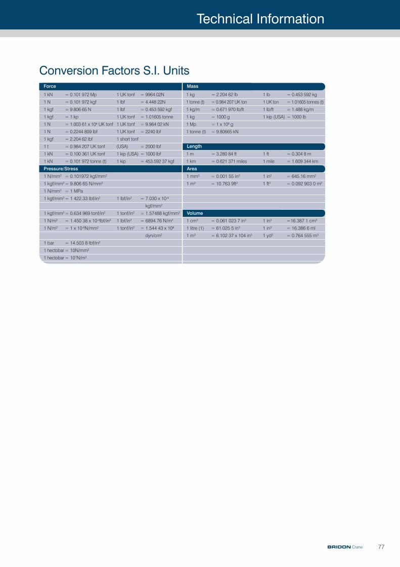
Technical Information
77
Conversion Factors S.I. UnitsForce Mass
Pressure/Stress Area
Volume
Length
1 kN = 0.101 972 Mp 1 UK tonf = 9964.02N
1 N = 0.101 972 kgf 1 lbf = 4.448 22N
1 kgf = 9.806 65 N 1 lbf = 0.453 592 kgf
1 kgf = 1 kp 1 UK tonf = 1.01605 tonne
1 N = 1.003 61 x 104 UK tonf 1 UK tonf = 9.964 02 kN
1 N = 0.2244 809 lbf 1 UK tonf = 2240 lbf
1 kgf = 2.204 62 lbf 1 short tonf
1 t = 0.984 207 UK tonf (USA) = 2000 lbf
1 kN = 0.100 361 UK tonf 1 kip (USA) = 1000 lbf
1 kN = 0.101 972 tonne (t) 1 kip = 453.592 37 kgf
1 kg = 2.204 62 lb 1 lb = 0.453 592 kg
1 tonne (t) = 0.984 207 UK ton 1 UK ton = 1.01605 tonnes (t)
1 kg/m = 0.671 970 lb/ft 1 lb/ft = 1.488 kg/m
1 kg = 1000 g 1 kip (USA) = 1000 lb
1 Mp = 1 x 10⁶ g
1 tonne (t) = 9.80665 kN
1 m = 3.280 84 ft 1 ft = 0.304 8 m
1 km = 0.621 371 miles 1 mile = 1.609 344 km
1 N/mm2 = 0.101972 kgf/mm2
1 kgf/mm2= 9.806 65 N/mm2
1 N/mm2 = 1 MPa
1 kgf/mm2= 1 422.33 lbf/in2 1 lbf/in2 = 7.030 x 10⁻⁴
kgf/mm2
1 kgf/mm2= 0.634 969 tonf/in2 1 tonf/in2 = 1.57488 kgf/mm2
1 N/m2 = 1.450 38 x 10-4lbf/in2 1 lbf/in2 = 6894.76 N/m2
1 N/m2 = 1 x 10⁻⁶N/mm2 1 tonf/in2 = 1.544 43 x 108
dyn/cm2
1 bar = 14.503 8 lbf/in2
1 hectobar= 10N/mm2
1 hectobar= 107N/m2
1 mm2 = 0.001 55 in2 1 in2 = 645.16 mm2
1 m2 = 10.763 9ft2 1 ft2 = 0.092 903 0 m2
1 cm3 = 0.061 023 7 in3 1 in3 =16.387 1 cm3
1 litre (1) = 61.025 5 in3 1 in3 = 16.386 6 ml
1 m3 = 6.102 37 x 104 in3 1 yd3 = 0.764 555 m3
BRIDON Crane
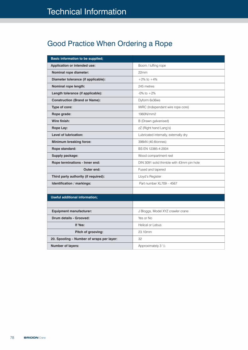
Technical Information
78
Good Practice When Ordering a Rope
BRIDON Crane
Basic information to be supplied;
Application or intended use: Boom / luffing rope
Nominal rope diameter: 22mm
Diameter tolerance (if applicable): +2% to +4%
Nominal rope length: 245 metres
Length tolerance (if applicable): -0% to +2%
Construction (Brand or Name): Dyform 6x36ws
Type of core: IWRC (Independent wire rope core)
Rope grade: 1960N/mm2
Wire finish: B (Drawn galvanised)
Rope Lay: zZ (Right hand Lang’s)
Level of lubrication: Lubricated internally, externally dry
Minimum breaking force: 398kN (40.6tonnes)
Rope standard: BS EN 12385-4:2004
Supply package: Wood compartment reel
Rope terminations - Inner end: DIN 3091 solid thimble with 43mm pin hole
Outer end: Fused and tapered
Third party authority (if required): Lloyd’s Register
Identification / markings: Part number XL709 – 4567
Useful additional information;
Equipment manufacturer: J Bloggs, Model XYZ crawler crane
Drum details - Grooved: Yes or No
If Yes: Helical or Lebus
Pitch of grooving: 23.10mm
20. Spooling – Number of wraps per layer: 32
Number of layers: Approximately 3 1/2

Contacts
79
UNITED KINGDOMDoncaster
Balby Carr Bank, DoncasterSouth YorkshireDN4 5JQUnited [email protected]: +44(0) 1302 565100Fax: +44(0) 1302 565190
UNITED STATESBridon American
C280 New Commerce Blvd.Wilkes BarrePA [email protected]: +1 800 521 5555Fax: +1 800 233 8362
GERMANYBridon International GmbH
Magdeburger Straße 14a D-45881 [email protected]: +49(0) 209 8001 0 Fax: +49(0) 209 8001 275
RUSSIABridon International Moscow
Ivovaya Street 2/8Building 1, Office 215129329 [email protected]: +7 495 1808001Fax: + 7 495 1809231
INDONESIAPT Bridon
Graha Inti Fauzi2nd FloorJl. Buncit Raya No.22Jakarta [email protected]: +62 (021) 791 81919Fax: +62 (021) 799 2640
AFRICAAngola
Sonils [email protected]: + 244 923 726890Fax: + 244 923 854180
Kwanda [email protected]: + 244 935 939761Fax: + 244 937 638565
SOUTH [email protected]: +27 (0) 11 867 3987Cell: +27 (0) 79 887 2747Fax: +27 (0) 11 867 3987
MIDDLE EASTBridon Middle East
PO Box 16931Dubai United Arab [email protected]: +971 488 35 129 Fax: +971 488 35 689
SINGAPOREBridon Singapore (Pte) Ltd.
Loyang Offshore Supply Base(SOPS Way)Box No: 5064Loyang CrescentSingapore [email protected]: +65 654 64 611Fax: +65 654 64 622
CHINABridon Hong Kong Ltd.
Unit B G/F Roxy Industrial Centre 58-66 Tai Lin Pai Road Kwai Chung Northern Territory Hong Kong [email protected]: +852 240 11 166Fax: +852 240 11 232
Bridon Hangzhou
57 Yonghua StreetXiacheng DistrictHangzhou CityZhejiang [email protected]: +86 571 8581 8780Fax: +86 571 8813 3310
[email protected]: +61 429 999 756
NEW ZEALAND6-10 Greenmount DriveEast TamakiPO Box 14 422 [email protected]: +64 9 2744299Fax: +64 9 2747982
BRIDONSales Offices
BRIDON Crane

Ground Floor, Icon Building, First Point, Balby Carr Bank,Doncaster, South YorkshireDN4 5JQ United Kingdom
Phone: +44(0) 1302 565100Fax: +44(0) 1302 565190Email: [email protected]
02/201
1 Editio
n 7
www.bridon.com