brief description specification and performance 3. … 1. brief description the temporarily...
TRANSCRIPT

1
1. Brief description
The temporarily installed suspended access equipment is multipurpose and highly efficient
construction machinery applicable to work at heights. It is a substitute of traditional scaffold used for
exterior wall construction, decoration, cleaning and maintenance of high-rising buildings, such as
mortaring, decorating walls with mosaic, painting, fixing windows and cleaning etc. It is also ideal for
applications such as installation of elevators, the welding of seagoing ship in ship building industry,
cleaning of oil-based paint, big –size tanks, high chimneys, bridges and large dams.
This equipment is accord with the national standard GB19155-2003, it is easy in operation and
maintenance.
2. Specification and Performance
Model description : Z L P description X X X
Z: Decoration machinery L: Suspended access equipment
P: Identity symbol: P----climb type X X X : Main technical parameters code (kg)
3. Operating principle and structure feature
ZLP Series suspended access equipment consists of the hoist, suspended platform, safety lock, suspension
mechanism, working wire rope, safety wire rope and electric control system. (See figure 1)
Figure1: Suspended access equipment

2
Main technical parameters
Model and parametersItem
ZLP800 ZLP630 ZLP500
Rated load 800 kg 630 kg 500 kg
Ascend speed 8~10 m/min 9~11 m/min 9~11 m/min
Suspended platform size
( L×W)
(2.5m×3) ×0.69 (2m×3) ×0.69 (2.5m×2) ×0.69
Wire rope 4×25Fi+PP-8.6 or
4×31SW+PP-8.6
4×25Fi+PP-8.3 or
4×31SW+FC-8.3
Hoist model LTD 8.0 LTD 6.3 LTD 6.3
Rated lifting force 8KN 6.3KN 5 KN
Power 1.8 KW 1.5 KW 1.5 KW
Voltage AC220V,240V,380V,415V and etc.Hoist
Electric
motor Braking
torque
15 N.m
Type LST30/LST20/LSG20
Steel rope angle
adjusting range (°)
3°~8°
Allowable compact
force
≤20KN
Rope lock distance ≤100m
Safety lock
Diameter of steel rope 8.6mm 8.3mm 8.3mm
Height adjustment 1.15m~1.75mSuspension
MechanismFront beam extent
1.1~1.6m (should reduce the load on the suspended
platform when extent is 1.5m or more)
Suspended platform
(including hoist, safety
lock, electric control
box)
610Kg (steel)
450Kg (aluminum)
480Kg (steel)
360Kg (aluminum)
410Kg (steel)
300Kg (aluminum)
Suspension mechanism 2×175Kg
Balance weight 1000Kg 900Kg 750Kg
Machine
weight
Whole machine weight
(not including wire rope
and cable)
2000Kg (steel)
1830Kg(aluminum)
1790Kg (steel)
1650Kg(aluminum)
1570Kg (steel)
1450Kg(aluminum)
The voltage and frequency of the motor can be manufactured to meet the needs of the
buyer’s requirements.

3
3.1 Suspension mechanism
The suspended mechanism is the heavy-duty steel frame structure erected at top of working profile as
the supporting equipment, bearing the rated and the load of the platform. Each suspended access
equipment take two sets of suspension mechanism. The force applied by the suspension mechanism on the
building or supporting structure shall meet relevant loading requirements of building structure.
(See figure 2)
1. Front beam 2. Front support 3. Tommy bar 4. Middle beam 5. Rear beam
6. Coupling sleeve 7. Rear support 8. Balance weight 9. Upper column
10. Reinforce wire rope 11. Turnbuckle
3.1.1
The suspension mechanism consists of front beam, middle beam, rear beam, front seat, rear seat, upper
column, balance weight, reinforce wire rope and tommy bar etc. To meet the requirement of working
condition, the front and rear beam as well as the height of suspension mechanism is adjustable within
certain range. Moreover, rollers are equipped to the base so that the suspension mechanism can be moved.
For the details of structure, see attached figure1: suspension mechanism
3.1.2 The configuration of the suspension mechanism shall meet the following in equation:
K=G*b/ (F*a)>=2
K------------------anti-upset safely coefficient
G------------------mass of the balance weight and rear seat (kg)
a-------------------extent of the front beam (m)
F-------------------Total mass of the platform, hoist, and electric system. Safety lock, wire rope and
rated load, plus wind pressure (kg)
b-------------------distance between the front seat and rear seat (m)
When the extent (a) of the front beam is 1.5m or more, the load on the suspended platform should be
reduced.
(Referring to attached table1)
3.2 Suspended platform

4
3.2.1 The suspended platform, welded with profiled steel pipes. The parts can be jointed with bolts and
nuts. The length of the standard section is 2.5m or 2m.
3.2.2 The balustrade on the working side is 970mm high and the balustrade on the back side is 1120mm
high. The floor has anti-slip strips.
For details of structure, see attached figure 2: suspended platform. (Page 18)
3.3 Hoist
3.3.1 The hoists for ZLP800 (A) consists of electromagnetic brake motor, centrifugal speed limiter and
dual speed reduction system and pulling rope system etc.
The hoists adopts type“S”crawling and rising mechanism.
For details of structure, see attached figure3: hoist (A) for ZLP800(A) and attached figure4: hoist (B) for
ZLP800 (B).
3.3.2 The hoist for ZLP800 (B) /ZLP630 /ZLP500 consist of electromagnetic brake motor, centrifugal
speed limiter and dual speed reduction system and pulling rope system ect.
The hoist adopts type (a) crawling and rising mechanism.
For details of the structure, see attached Figure 3: Hoist for ZLP500/ZLP630/ZLP 800(B) ( page 19)
3.3.3 The hoist is provided with automatic rope feeding function, and operators just need to insert wire
ropes into the inlet of the hoist. (See figure 3)
3.3.4 The electromagnetic brake of the hoist motor is able to be auto-engaged to produce braking torque
that stops and supports the suspended platform. In the event of power failure or emergency, the fork of
manual descending unit(inside the handle of hoist)can be used to plug in the fork hole of electromagnetic
brake (inside the motor hood) to raise fork and open brake so as to prompt the suspended platform to slide
downwards at even speed (See figure 4)
3.3.5 The cooling of hoist is by the lubrication of gear oil, which should be replaced at an interval of
6-12months pursuant to practical situation. The No.18dual-curve gear oil is recommended to use, and the
oil volume of hoist is 1.2libers for ZLP800, and 2liters for ZLP630 or ZLP500.If used in extreme cold
winter, the No80W/90 general vehicle gear oil is the best.
Figure 3 Figure 4
3.4 Safety lock
Safety lock is a separate mechanical unit that can automatically lock safety wire rope when the working
wire rope is broken or the suspended platform tilts to its limits.
There are two kinds of safety locks. Anti-proof safety lock or centrifugal speed-limit safety lock should be
used according to different shape suspended platform.

5
3.4.1 The tilt-proof safety lock ( see figure 5) consists of parts as rope clip, sleeve plate, torsion spring,
bracket, swing arm and roller. It is so arranged that the working wire rope is put against the roller on the
swing arm to make the rope clip open and allow the smooth pass of safety wire rope. If the suspended
platform tilts to its limits or working wire rope break, the pressure on the swing arm of safety lock will
reduce or impair. The safety rope clip swiftly closes and locks safety wire rope to prevent suspended
platform from dropping or tilting by the friction as that in between torsion spring, rope clip and wire rope.
When anti-tilting safety lock is applied, the tilt angle of suspended platform should be 3 degree-8 degree,
the model ZLP800, ZLP630 and ZLP500 take two anti-tilting safety lock.
Figure 5 Figure 6
3.4.2 The centrifugal speed-limit safety lock (see figure 6) is based on the principle of centrifugal
speed-limit. When centrifugal safety lock is applied, the safety wire rope is led through the rope sheave,
which is connected with the centrifugal speed-limit. When the suspended platform’s downward movement
speed exceeds the limits, the kicker of centrifugal speed limit triggers the clamping device and locks the
safety wire rope within 20cm distance to stop the operation of platform.(the single suspension point access
equipment usually takes this type safety lock)
3.4.3The safety lock is marked by factory for the first time. After the first marking is effective, the
professional technician should conduct maintenance and service at an interval of 12months and remark at
the end of 12 months.(For the safety locks operating in the dusts, corrosive materials and adhesive
materials, the overhaul and second marking are required on 6 months basis)
3.5 Electric control system
The electric control system consists of electric control box, electromagnetic braking motor and handle
switch etc. The upward and downward movement of suspended platform is controlled by two
electromagnetic braking motors. (See figure 7)
3.5.1 Power supply
The power supply adopts 3-phases and 5-wire system in which the5-core cable of 2.5mm2 is going
through Q1 power socket to control box, which is powered on by 3-phases leakage breaker.X1,X2 and X3
ARE 3-Phrase power line, and PE is grounding line. The users should connect power in 3-phases and
5-wire system. (see attached figure 4: Three Phase Electric Control Diagram) ( page 21)

6
Figure 7
1. Left upper limit switch 2. Handle switch 3. Left motor 4. Right motor
5. Emergency stop 6. Power cable 7. Upward button 8. Downward button
9. Turning switch 10. Right upper limit switch
3.5.2 Emergency braking, overloading protecting circuit
The power is transmitted to motor via general contactor KM1, motor control contactor KM2, KM3 and
thermal relay FR1, FR2 and motor socket Q3and Q3, Q4. If in any abnormal situation, emergency
braking can be executed to ensure safety, that is to press the emergency stop switch on the panel of
electric control box so that the general contactor KM1 loses power, the motor is power off and the
hoist stops running. Thermal relay can be power-off automatically in case of the motor overloading.
3.5.3 Circuit of motor brake
The motor brake is installed inside the hood of motor; the voltage is rectified to DC99V forAC220V
single phase power (DC108V for ac240V single phase power) via half-wave rectifier module. The brake
rectifier module is installed inside of motor box.
3.5.4 Control circuit
The control circuit is controlled by 36V or 24V power transformed from control transformer T, which is
easy to control. It can be controlled in electric control box and handle switch. the motor can run
simultaneously and independently, which is governed by turning the switch on the panel of the control box.
When the switch is turned to one side, the single motor running is realized.
3.5.5 Upper limited switch and alarm circuit.
Upper limit stopper is set on the upper working area of the suspended platform. When the travel switch
actuates the limit, the motors will stop operation and the alarm bell will ring.
3.5.6 To facilitate the work, terminals N1 and X11in the electric control box are offered to supply power to
lighting and hand-held tools. However, the use of big power consumers such as welding machines and
iodine lamps is prohibited so as to prevent the circuit and elements from damage.
3.6 Wire rope

7
3.6.1 The wire ropes used in hoists for the equipment is special galvanized wire rope, the wire rope used
for ZLP800, its structure is 4×31SW +PP-8.6 or 4×25Fi+PP-8.6.
The wire rope used for ZLP630 or ZLP500, its structure is 4 × 31SW+FC-8.3 or 4 ×
25Fi+PP-8.3,diameter is 8.3mm.
3.6.2 The fixing method at the end of wire rope is as per the specification of GB5144-86 (see figure 8), U
bolt is fixed on the rear portion of wire ropes, and clip is fixed on the working section of the wire ropes,
which cannot be mixed up. The wire rope clip cannot be alternately arranged on the wire rope, the number
of clip is no less than 3, and the spacing A is about 60mm.Tighteen from the loop ring in sequence.
The wire rope must be designated by our factory.
It is forbidden to use wire ropes connected and extended in any way.
3.6.3The maintenance and inspection of wire ropes
The wire rope should be kept and maintained in a proper way to prevent corrosion and pollution and the
wire ropes should be regularly inspected for deformation and breakage. The rejection of wire rope is as per
the specification of GB59722.
Special notice:
The wire ropes should be replaced in any one of the situations below:
a. The loosening, twisting, untwisting, or any other deformation and distortion.
b. The wire rope should be rejected when the wire breaking number within the range of “ab” spacing
reaches5 (see figure 9).
Figure 9
When any corrosion or abrasion on the surface of wire rope, the standard for rejection is reduced further.
The percentage of reduction is that the maximum allowable breaking number5 times the percentage of the
corrosion or abrasion on the surface and the wire rope is loose.
c. Obvious corrosion on the wire rope, that is .the concave pit on the surface and the wire rope is loose.
d. The nominal diameter of wire rope is reduced by 6%, even if there is no twist breakage.
e. When the abrasion of outer rim of wire rope to 40% of diameter.
f. The damage or accumulation incurred by the heat or electric arc.
4. Installation

8
4.1The preparation before installation
Prior to installation, please check up the number of parts as shown in the packing list. Check the condition
of each and all the parts and components
4.2 Installation of suspension mechanism
(See attached figure1: suspension mechanism)
4.2.1 Insert the tommy bars into the front support and rear support respectively and tighten the bolts to
form front support column and rear support column (the height of which should be adjusted with the
1.15-1.75m range according to the height of parapet).
4.2.2 Lead the front beam (with hanger plate) through the sleeve on front support column (the extent of the
front beam dependent on actual needs), put on the upper column and tighten the bolts and nuts.
4.2.3 Slide the middle beam onto the front beam (length dependent on actual needs), fix and tighten
coupling sleeve by using the two boles at the end, and then fix and tighten the bolts and nuts.
4.2.4 slide the rear beams in to the middle beams (length dependent on actual needs), fix and tighten the
bolts and nuts on one end. Put the other end into the rear support column sleeve, mount the coupling sleeve
by using the two holes at the end, and then fix and tighten the bolts and nuts.
4.2.5 Lead the open side of the turnbuckle fixed on the coupling sleeve on rear support column. Lead one
end of the reinforcing wire rope (7m long) into the coupling sleeve of front beam and tighten the rope
clamp (the direction as shown in the figure8). Lead the reinforcing wire rope to the rope sheave on upper
column and the other end through the hole of close side of the turnbuckle, tighten the rope clamp. Adjust
the screw bar of the turnbuckle and tighten the reinforce wire rope to raise the extent of front beam about
3cm.
4.2.6 Tighten the working wire rope and safety wire rope with rope clamps (the direction as shown figure8)
and put the stopper on safety wire rope as may needed according to the actual conditions.
4.2.7 Place the suspension mechanism to its working position with the reach of front hanger plate out of
the working wall space about 60cm. the distance between two front hanger plates of suspension
mechanism should be the same as the length of the suspended platform. Load the balance weight and
slowly release the wire rope.
4.3 Installation of suspended platform
4.3.1 Put the bottom plate flat on the ground, mount the balustrade and place the bolts and nuts in position
without tightening them for the time being (see attached figure2) (page 18)
4.3.2 Install the caster wheel on the hoist-mounting frame. Have the hoist-mounting frame of at the ends of
suspended platform; place the bolts and nuts in position without tightening them for the time being.
4.3.3 Check that the installation of above parts is correct.
4.3.4 Tighten the bolts connecting the balustrades and bottom plate, as well as the bolts connecting the
balustrades together. Tighten the bolts connecting the balustrades and the hoist-mounting frame.
4.4 Installation of hoists, safety locks and electric control box.
4.4.1 For ZLP800, Install the hoist on the hoist-mounting frame, fix with handles and locking pins (see
figure10). Install safety lock on the bracket of the hoist-mounting frame, fix and tighten with bolts.

9
Figure 10
1. Hoisting-mounting frame 2. Pin shaft 3. Safety lock 4. Upper limit stopper 5. Electric control
box 7. Working wire rope 8. Pin locking 9. Heavy hammer
For ZLP630 or ZLP500, install the hoists on the hoist-mounting frame, fix with bolts, nuts, handles and
locking pins (see figure 11). Install safety lock on the bracket of the hoist-mounting frame, fix and tighten
with bolts.
Figure 11

10
1. Hoisting-mounting frame 2. Pin shaft 3. Safety lock 4. Upper limit stopper
5. Electric control box 6. Working wire rope 7. Bolt M10×120 8. Pin locking
9. Nut 10.Heavy hammer
4.4.2 Install and hang the electric control box in the middle of balustrade of the suspended platform.
4.4.3 Insert motor plug and handle switch plug. Install the upper limit travel switch to the right position of
safety lock. Power plug should be inserting into the power socket and power cable should be connected
based on three-phases and five-wire system
5. Application and inspection
5.1 Inspection and adjustment5.1.1 Check if the wiring is correct. The voltage of power should be within the range of 380V±5 %(415V
±5%). After the power is connected, push the testing button on the power leakage breaker, and power
leakage breaker should work swiftly. Close the door of electric control box and inspect if handle switch,
turning switch and motor is normal.
5.1.2 The inspection and adjustment of electromagnetic brake. The spacing D between armature
Figure 121. Inner hexagon screw 2. Electromagnectic disc 3. Hollow screw 4. Spring
5. Armature 6. Friction disc 7. Motor cover
and electromagnetic disc should be within the range of 0.5-0.6mm, its structure is shown in figure9. First
loosen the inner hexagon screw 1 on the electromagnetic disc2, and then turn hollow screw 3 to adjust
spacing around, and finally retighten inner hexagon screw1. Power on to check the operation of
electromagnetic armature, the armature must separate with friction disc completely after being absorbed,
and no clog after power is off. The armature should press the spring disc completely under the force of
spring.
5.1.3 Rope passing inspection
Turn the turning switch on the panel of electric control box to the hoist ready for the rope passing. The
working wire rope will insert into the upper hole of hoist after passing between the limiting wheel and
retainer ring of safety lock. Start upward button, the hoist will wind automatically to finish the rope
passing and positioning of wire rope (During rope passing, close attention should be paid to any abnormal
condition , if any ,stop passing immediately). After the working wire rope is positioned, the safety lock
will be opened automatically to insert the safety wire rope from the upper end hole of safety lock. (The
operating procedure on the other side of hoist is the same)
5.1.4 After the wire ropes at both two sides are passed, raise and level the suspended platform to the level l
meter above the ground surface. Mount heavy hammer on safety wire rope 15cm off the ground.
5.1.5 The redundant wore ropes should be handles with care; they should be packed to prevent damage.

11
5.2 Test run
5.2.1 The user should prepare a safety rope to be fixed independently on the attachment over the operating
area. The operator should wear safety helmet and safety strap according to related
regulations, fasten the safety strap knuckle on the safety rope.
5.2.2 Check the condition of locking rope, the detailed procedure is as follows: turn the turning switch on
the panel of the electric control box to the middle, and raise the suspended platform 1~2cm and stop, and
then turn the turning switch to another side to make suspended platform tilt. When the suspended platform
tilts to 3°~8, the safety lock will lock the safety wire rope. When raising the lower end of suspended
platform to the leveling condition, safety lock will be reset automatically, and the safety wire rope will be
in free condition in safety lock. (The left and right safety lock should be checked as per the procedures
above).
5.2.3 Zero load testing: No abnormal sound in hoist, the operation of electromagnetic brake is flexible and
reliable. Press “emergency stop” button, the suspended platform should stop operation.
5.2.4 Manual descending inspection: Take the fork out of the hoist handle, and plug (insert) it into the fork
hole inside of motor hood to rise up, the suspended platform should be moving smoothly at the even speed
no greater than 1.5 times rated speed.
5.2.5 Adjustment of the upper limit stopper: ascend the suspended platform to the working height; adjust
the upper limit stopper and angle of swing arm of the upper limit switch.
5.2.6 Rated load testing: the rated load should be evenly distributed on the working platform. The
operation process no abnormal sound and when stopping no sliding movement. The safety lock should
lock the safety wire rope flexibly and reliably when the platform is tilting.
5.3 Routine inspection.
5.3.1 Inspection prior to use: no abnormal condition on the hoist and connection between hoist and
suspended platform, normal tightening of wire rope, no over-abrasion of wire rope and breakage; The wire
rope up to the rejection standard should be replaced, the heavy hammer hung below the wire rope should
be installed correctly; the electric control box, power cable, control button and plug should be in good
condition, , and the handle switch should be flexible and reliable without power leakage.
5.3.2 Power-on check: Please check up the operating condition of suspended platform as per 5.2.3, 5.2.4,
5.2.5, there are should be no abnormal and vibration existing in hoist, and braking of electromagnetic
brake should be flexible, and the locking function of safety lock should be good.
5.3.3 During operation, the foreign matters as mortar, glue, waste paper and painting are not allowed to
come into safety lock. After daily use, the suspended platform should be lowered to ground and the
operating wire rope be loosen to make the swing arm of safety lock be in the loose state. Turn off the
power and lock electric control box. When stored in open air, the rainproof measures should be taken to
prevent rain from entering hoist, safety lock and electric control box. The wire ropes are not allowed to
curve and be stained with grease and dusts, nor the welding slugs and ablation. If any condition as in 3.6.3,
it should be replaced immediately.
6. Safety operation procedure
6.1 The suspended access equipment should only be operated and maintained by qualified personnel with
adequate technical training.
6.2 Personnel in the platform should wear safety helmet and be fastened to safety rope with safety strap as

12
required by relevant regulations.
6.3 The platform must be protectively grounded and the load applied on the platform should be roughly
distributed in a even way. It is prohibited to have the platform overloaded or to operate the platform with
the hoists or safety lock with the trouble.
6.4 When the platform is in its normal operation, it is prohibited to manually brake the motors or safety
lock, so as to prevent and accident from happening.
6.5 During operation of platform, the operator should keep an eye on the platform’s operation condition
and promptly shoot any hidden trouble possibly leading to accidents.
6.6 When the limit switch is activated, the operation of platform will automatically halted and the buzzer
will signal the alarm. Under the circumstances, lower the platform promptly to have the limit switch be
away from the stopper.
6.7 The platform should be adjusted promptly if it is tilting and the height drop of two ends should be no
higher than 15cm.
6.8 In case of power break during operation, shut down the power first. If it is needed to have the
suspended platform lowered back onto the ground, use same method of ‘5.2.4 manual descending
inspection’ to operate the electromagnetic brakes at the same time to have the platform lowered smoothly
onto the ground.
6.9 The working wire rope and safety wire rope should not be bent and should be prevent from the
contamination of mortar and other foreign materials. They should be replaced as required by the operation
manual in case of cracking, breaking, peeling, distortion, flossing and corrosion. The safety wire rope
should be prevented from contacting grease or oil.
6.10 In case of working wire rope breakage during operation, the personnel in the platform should keep
calm and composed and leave the platform under the prerequisite of ensured safety. After maintenance and
repair personnel enter the platform, the first thing to do is to take anti-dropping measures by having the
clamp of safety wire rope hold the platform fast or by fastening the platform with the wire rope secured on
the building roof. Then, pull the replacing wire rope through the hoist, press the up button to have the
platform move upward. If the suspended access equipment works normally, release the safety lock
cautiously, detach the fixing wire rope and lower the platform down to the ground. It will not be put into
operation again until it passes the stringent inspection.
6.11 The operation of suspended access equipment should meet relevant regulations regarding work
performed at heights. The equipment should not used under such weather conditions as thunder, rain, fog
and wind of Grade 5 (wind speed 8.3m/s) or higher.
6.12 The suspended access equipment should not be used in the area within 10m away from high-voltage
power cables.
6.13 Never use additional equipment, i.e. ladders, boxes, to obtain increased height in the suspended
platform. Never use additional extensions to exceed the permissible length of the platform. Ensure that all
the materials and equipment are safety stored within the confines of the platform.
6.14 The suspended access equipment should avoid contacting corrosive gas and liquid. If there is no
alternative available, anti-corrosion and segregation measures should be taken in its operation.
6.15 The safety 1ock should be checked and its moving parts should be lubricated regularly during its
service life and it should not be dismantled without authorization. Special attention should be paid to the
labeled service of the safety lock..
6.16. When the suspended platform is stored in the open air, measures should be taken to prevent
the rainwater from entering into the hoist, safety lock and electric control box.

13
6.17 When the wire rope is removed from platform, it should be winded to form a bundle and stored
promptly.
6.18 The suspended access equipment should be stored in a dry and well ventilated warehouse free of
corrosive gases.
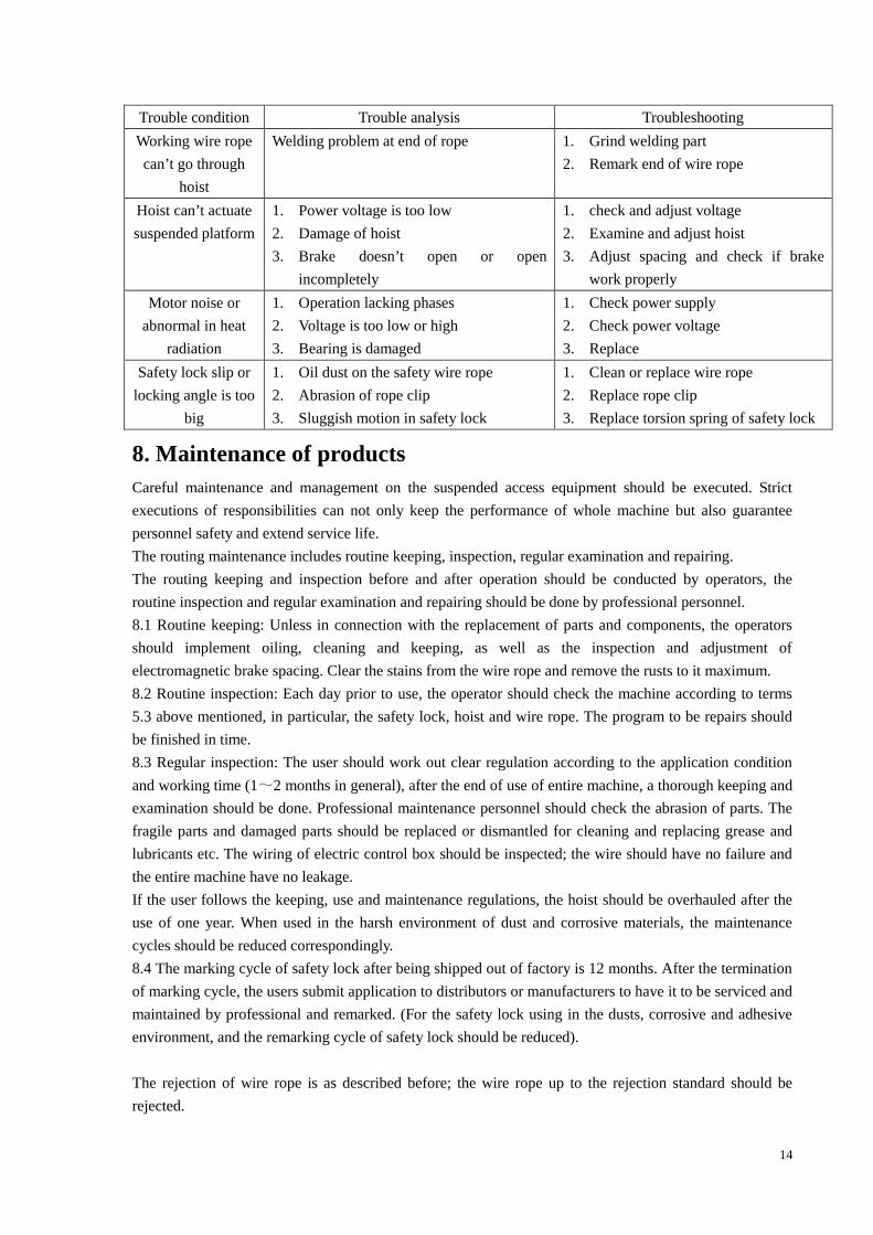
7. Common troubles and troubleshooting
See the following table for the common troubles, causes and troubleshooting:
Trouble Analysis of causes Troubleshooting
Suspended platform
slides down in
static condition
1. Motor electromagnetic
brake fails.
2. The spacing between brake and armature
is over too big
1. Replace electromagnetic brake
2. shorten the spacing, the reasonable
spacing should be at 0.5 ~0.6mm( see
5.1.2)
Suspended platform
doesn’t stop in
ascending and
descending
1. the main contact point of AC contactor
disengages
2. Control button fails.
1. Push down “emergency stop” to stop
suspended platform, replace
contactor.
2. First stop suspended platform as per
the methods above, and then replace
control button.
Power supply is abnormal:
1. Leakage breaker disengage
2. Phase lacking
1. Check to see if any leakage, and take
preventive measures.
2. Check if the 3-phase power is normal
and reconnect
Suspended platform
can’t ascend and
descend
Failure of control line
1. Control transformer fails
2. Thermal relay breaks or damages
3. fuse of contactor damages
4. Poor contact in plug
1. Replace transformer
2. Switch or replace thermal relay
3. Replace fuse of contactor
4. Check and tighten plug or place
1. Sensitivity difference in motor brake.
2. Spring of centrifugal speed limiter
loose.
3. Difference in motor rotating speed, and
hoist rope pulling
1. Adjust the spacing of motor brake
2. Replace centrifugal speed limiter
spring
3. Check the rope pressing device or
place motor with incorrect rotating
speed
Suspended platform
tilts
Uneven in the load of suspended platform Adjust the load of suspended platform
Abnormal noises in
suspended platform
Parts of hoist is damaged Replace
Hoist at one side
stop motion or
motor heats and
gives smoke
1. Braking armature stop moving or
spacing between armature and friction
disc is too small
2. Coil of brake is burnt to damage.
Damage of switch.
3. Short circuit and damage of rectifier
4. Damage of thermal replay or contactor
1. Adjust the spacing between brake
armature and friction disc or replace
armature.
2. Replace brake coil
3. Replace rectifier
4. Replace relevant electrical parts
5. Replace switch
14
Trouble condition Trouble analysis Troubleshooting
Working wire rope
can’t go through
hoist
Welding problem at end of rope 1. Grind welding part
2. Remark end of wire rope
Hoist can’t actuate
suspended platform
1. Power voltage is too low
2. Damage of hoist
3. Brake doesn’t open or open
incompletely
1. check and adjust voltage
2. Examine and adjust hoist
3. Adjust spacing and check if brake
work properly
Motor noise or
abnormal in heat
radiation
1. Operation lacking phases
2. Voltage is too low or high
3. Bearing is damaged
1. Check power supply
2. Check power voltage
3. Replace
Safety lock slip or
locking angle is too
big
1. Oil dust on the safety wire rope
2. Abrasion of rope clip
3. Sluggish motion in safety lock
1. Clean or replace wire rope
2. Replace rope clip
3. Replace torsion spring of safety lock
8. Maintenance of products
Careful maintenance and management on the suspended access equipment should be executed. Strict
executions of responsibilities can not only keep the performance of whole machine but also guarantee
personnel safety and extend service life.
The routing maintenance includes routine keeping, inspection, regular examination and repairing.
The routing keeping and inspection before and after operation should be conducted by operators, the
routine inspection and regular examination and repairing should be done by professional personnel.
8.1 Routine keeping: Unless in connection with the replacement of parts and components, the operators
should implement oiling, cleaning and keeping, as well as the inspection and adjustment of
electromagnetic brake spacing. Clear the stains from the wire rope and remove the rusts to it maximum.
8.2 Routine inspection: Each day prior to use, the operator should check the machine according to terms
5.3 above mentioned, in particular, the safety lock, hoist and wire rope. The program to be repairs should
be finished in time.
8.3 Regular inspection: The user should work out clear regulation according to the application condition
and working time (1~2 months in general), after the end of use of entire machine, a thorough keeping and
examination should be done. Professional maintenance personnel should check the abrasion of parts. The
fragile parts and damaged parts should be replaced or dismantled for cleaning and replacing grease and
lubricants etc. The wiring of electric control box should be inspected; the wire should have no failure and
the entire machine have no leakage.
If the user follows the keeping, use and maintenance regulations, the hoist should be overhauled after the
use of one year. When used in the harsh environment of dust and corrosive materials, the maintenance
cycles should be reduced correspondingly.
8.4 The marking cycle of safety lock after being shipped out of factory is 12 months. After the termination
of marking cycle, the users submit application to distributors or manufacturers to have it to be serviced and
maintained by professional and remarked. (For the safety lock using in the dusts, corrosive and adhesive
environment, and the remarking cycle of safety lock should be reduced).
The rejection of wire rope is as described before; the wire rope up to the rejection standard should be
rejected.

15
9. Handing and storage
The products should be stored in dry and ventilating warehouse without corrosive gas to avoid corrosion.
If storage is over one year, a second maintenance should be conducted.
10. Fragile parts
No. Item Drawing No. Installation part
1 Wire rope 4×31SW+PP-8.6 or
4×25Fi+ PP-8.6
Hoist for ZLP800
2 Wire rope 4×31SW +FC-8.3 or
4×25Fi +PP-8.3
Hoist for ZLP500 / ZLP630
3 Braking friction disc Y2-100L-4 Motor for ZLP800
4 Braking friction disc Y2-90L-4 Motor for ZLP630/ ZLP500
5 Friction assembly of centrifugal
speed limiter
LTD80.4.1 Motor shaft of hoist for ZLP800
6 Friction assembly of centrifugal
speed limiter
LTD63.4.1 Motor shaft of hoist for ZLP630
/ZLP500
7 Rope guide LTD63.1
8 Turing switch LW5-16 Electric control box
9 Emergency stop LAY3 Electric control box
10 Brake rectifier module VC1,VC2 Motor box
11 Upper limit travel switch LXK3-20S/T On Safety lock
12 Fuse Electric control box
Attached table 1: Relation between working height, extent of front beam and
permissible load.
Permissible load
(kg)
Model Balance
weight
(kg)
Working
height
(m)
Extent
of front
beam
(m)
Distance
between front
and rear base
(m)
Steel Aluminum
1.5 4.6 800 80050
1.7 4.4 570 730
1.3 4.6 800 800
1.5 4.6 750 800
100
1.7 4.4 510 670
1.3 4.6 800 800
1.5 4.6 730 800
120
1.7 4.4 490 650
1.3 4.6 800 800
ZLP800 1000
150
1.5 4.6 690 800
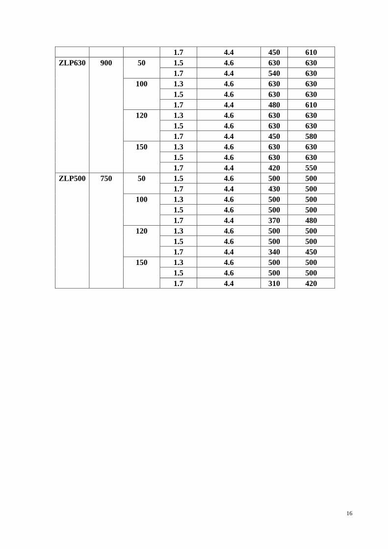
16
1.7 4.4 450 610
1.5 4.6 630 63050
1.7 4.4 540 630
1.3 4.6 630 630
1.5 4.6 630 630
100
1.7 4.4 480 610
1.3 4.6 630 630
1.5 4.6 630 630
120
1.7 4.4 450 580
1.3 4.6 630 630
1.5 4.6 630 630
ZLP630 900
150
1.7 4.4 420 550
1.5 4.6 500 50050
1.7 4.4 430 500
1.3 4.6 500 500
1.5 4.6 500 500
100
1.7 4.4 370 480
1.3 4.6 500 500
1.5 4.6 500 500
120
1.7 4.4 340 450
1.3 4.6 500 500
1.5 4.6 500 500
ZLP500 750
150
1.7 4.4 310 420

17
Attached figure 1: Suspension mechanism
1. Front support 2. Front tommy bar 3. Middle beam (70mm×70mm) 4. Upper column
5. Bolt 6. Branch pipe of balance weight 7. Rear support 8.Rear beam
9. rigging screw M20 10. Coupling sleeve 11. Tommy bar 12. Balance weight
13. Cutting sleeve of wire rope 14. Spindle sleeve 15. Wrist 16. Lifting piston
17. Big connecting sleeve 18. Cotter pin 19. Front beam (83mm×83mm)
20. Bolt M14*150 21. Wire rope Y-10 22. Intensive wire rope

18
Attached figure 2: Suspended Platform
1. Hoisting-mounting frame 2. Bracket 3. Bottom plate 4.Front balustrade
5. Bolt M12×140 6. Big washer 7. Nut 8. Bolt M12×10 9. Back balustrade
10. Caster wheel

19
Attached Figure 3: Hoist for ZLP500/ZLP630/ZLP 800(B)

20
Attached table 2: Parts list of hoist for ZLP500/ ZLP630/ ZLP800(B)
No. Name Quantity No. Name Quantity
1 Rope inlet pipe 1 31 Handle 1
2 Box 1 32 Pin 1
3 Alignment pin 2 33 Screw 2
4 Base plate of rope guide 1 34 Bearing 6004 1
5 Rope guide 1 35 Adjustment washer 1
6 Cover of rope guide 1 36 Screw 2
7 Gasket seal 1 37 Bearing 16007 1
8 Driving disc 1 38 Gasket sealing 1
9 Steel belt assembly 1 39 Washer 4
10 Screw 2 40 Screw 4
11 Bearing 6004 1 41 Front cover 1
12 Wire pressing unit 1 42 Motor 1
13 Cover 1 43 Key 1
14 Washer 3 44 O-shape gasket sealing 1
15 Screw 3 45 Centrifugal speed limiter 1
16 Nut 4 46 Shield ring 1
17 Shield ring 1 47 gasket sealing 1
18 Screw 4 48 Shield ring 1
19 Washer 4 49 Bearing 6005 1
20 Bolt 4 50 Fork 1
21 Washer 4 51 Shield ring 2
22 Rope outlet pipe 1 52 Bearing 6203 1
23 Shield ring 1 53 Shield cover 1
24 Key 1 54 Gasket sealing 1
25 Worm 1 55 Screw 1
26 Shield ring 1 56 Worm-wheel 1
27 Nut 4 57 Adjustment washer 2
28 Pinion shaft 1 58 O-shape gasket sealing 1
29 Bearing 6207 1 59 Plug 1
30 Sleeve 1

21
Attached figure 4: Three Phase Electric control diagram

22
Attached figure 5: Three Phase Wiring terminal board diagram

23
Attached figure 6: Three Phase Power plug-in component diagram
24
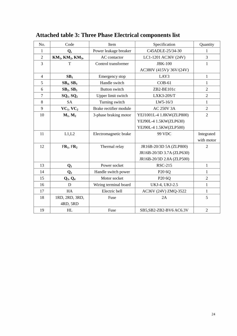
Attached table 3: Three Phase Electrical components list
No. Code Item Specification Quantity
1 Qs Power leakage breaker C45ADLE-25/34-30 1
2 KM1, KM2, KM3, AC contactor LC1-1201 AC36V (24V) 3
3 T Control transformer JBK-100
AC380V (415V)/ 36V/(24V)
1
4 SB1 Emergency stop LAY3 1
5 SB4, SB3 Handle switch COB-61 1
6 SB2, SB5 Button switch ZB2-BE101c 2
7 SQ1, SQ2 Upper limit switch LXK3-20S/T 2
8 SA Turning switch LW5-16/3 1
9 VC1, VC2 Brake rectifier module AC 250V 3A 2
10 M1, M2 3-phase braking motor YEJ1001L-4 1.8KW(ZLP800)
YEJ90L-4 1.5KW(ZLP630)
YEJ90L-4 1.5KW(ZLP500)
2
11 L1,L2 Electromagnetic brake 99 VDC Integrated
with motor
12 FR1, FR2 Thermal relay JR16B-20/3D 5A (ZLP800)
JR16B-20/3D 3.7A (ZLP630)
JR16B-20/3D 2.8A (ZLP500)
2
13 Q1 Power socket RSC-215 1
14 Q2 Handle switch power P20 6Q 1
15 Q3, Q4 Motor socket P20 6Q 2
16 D Wiring terminal board UKJ-4, UKJ-2.5 1
17 HA Electric bell AC36V (24V) ZMQ-3522 1
18 1RD, 2RD, 3RD,
4RD, 5RD
Fuse 2A 5
19 HL Fuse SB5,SB2-ZB2-BV6 AC6.3V 2