british standard bs 1757:1986
TRANSCRIPT

BRITISH STANDARD BS 1757:1986
Specification for
Power-driven mobile cranes
UDC [621.873.2/.3]-8

BS 1757:1986
This British Standard, having been prepared under the direction of the Mechanical Handling Standards Committee, was published under the authority of the Board of BSI and comes into effect on 31 July 1986.
© BSI 04-1999
First published July 1951First revision April 1964Second revision March 1981Third revision July 1986
The following BSI references relate to the work on this standard:Committee reference MHE/3Draft for comment 83/77707 DC
ISBN 0 580 15128 X
Committees responsible for this British Standard
The preparation of this British Standard was entrusted by the Mechanical Handling Standards Committee (MHE/-) to Technical Committee MHE/3, upon which the following bodies were represented:
Associated British Ports
Associated Offices Technical Committee
Association of Consulting Engineers
British Constructural Steelwork Association Ltd.
British Ports Association and the National Association of Ports Employers
Building Employers’ Confederation
Bureau of Engineer Surveyors
Construction Plant — Hire Association
Crown Agents for Oversea Governments and Administrations
Department of the Environment (Building Research Establishment)
Department of the Environment (Property Services Agency)
Department of Trade and Industry (Mechanical and Electrical Engineering Division)
Electricity Supply Industry in England and Wales
Engineering Equipment and Materials Users’ Association
Federation of Civil Engineering Contractors
Federation of Manufacturers of Construction Equipment and Cranes
Federation of Wire Rope Manufacturers of Great Britain
Health and Safety Executive
Independent Engineering Insurers’ Committee
Institute of Materials Handling
Institution of Mechanical Engineers
Institution of Production Engineers
Institution of Structural Engineers
Mechanical Handling Engineers’ Association
Ministry of Defence
Welding Institute
Coopted member
The following bodies were also represented in the drafting of the standard, through subcommittees and panels:
Association of Lorry-Loader Manufacturers and Importers
Engineer Surveyors Section of ASTMS
Amendments issued since publication
Amd. No. Date of issue Comments
BS 1757:1986
© BSI 04-1999 i
Contents
PageCommittees responsible Inside front coverForeword ivSection 1. General1 Scope 12 Definitions 13 Information to be supplied with the enquiry or order 24 Information to be supplied by the manufacturer at
the time of tender 25 Service conditions 36 Design of the crane 37 Identification 38 Materials 39 Stability 3Section 2. Structural10 Frame structures including jibs: equivalent inertia forces 511 Joints 5Section 3. Mechanical12 Steel wire ropes 613 Drums and rope reeving components 614 Lifting hooks 715 Shackles 716 Overhauling weight 717 Rope pulleys 718 Gearing 719 Rotating and fixed shafts and axles 720 Keys, keyways and splines 821 Clutches 822 Brakes for crane motions 823 Lubrication 924 Slewing 925 Guarding 926 Controls 927 Manual operation 1028 Crane driver’s station 1029 Internal combustion engines 1030 Pneumatic tyres 10Section 4. Electrical31 Electric motors and generators 1132 Control gear 1133 Protective gear 1134 Fixed cables, wiring and other conductors 1235 Cables for cable reels and similar applications 1236 Trailing cables 1237 Cable ratings 1238 Wiring diagram 1239 Lighting 1240 Radio interference 12

BS 1757:1986
ii © BSI 04-1999
PageSection 5. Hydraulic equipment41 General requirements 1342 Power transmission 13Section 6. Pneumatic equipment43 General requirements 1444 Application 14Section 7. Safety45 Safe working load charts 1546 Marking of hook and block weights 1547 Marking of outrigger beams 1548 Lattice strut jib connections 1549 Radius/jib angle indicators 1550 Safe load indicator 1551 Travelling with suspended loads 1552 Audible warning device 1653 Motion limits 1654 Level indicator 1655 Anemometer 1656 Danger of overhead power cables 1657 Instruction book 16Section 8. Testing58 General 1759 Tests to be carried out 1760 Test certificates 2361 Verification of crane details 23Section 9. Protection of crane structure62 Painting 24Appendix A Information recommended to be suppliedwith enquiry or order for cranes complying with BS 1757 34Appendix B Information to be supplied by manufacturerfor cranes complying with BS 1757 35Appendix C List of British Standards for materials andequipment used in the manufacture of cranes 37Appendix D Legislation that may affect mobile cranes inthe United Kingdom 40Appendix E The calculation of stability of lorry loaders 42Appendix F Typical form of test certificate 43Appendix G Crane stability 44Figure 1 — Elevation of typical jib configuration 20Figure 2 — Moment diagram for a typical lorry loader 24Figure 3 — Typical mobile full-slewing crane on wheels 25Figure 4 — Typical truck mounted telescopic jib crane(with lattice fly jib shown inset) and outriggers 26Figure 5 — Typical crawler mounted lattice jib crane 27Figure 6 — Typical jib configurations 28Figure 7 — Lorry loader: typical configurations 29Figure 8 — Typical turning radii 30Figure 9 — Typical lorry loader features 31

BS 1757:1986
© BSI 04-1999 iii
PageFigure 10 — Typical safe working load chart for a lorry loader 31Figure 11 — Rating of typical crane at intermediate telescopicjib lengths (stepped duties) 32Figure 12 — Rating of typical crane at intermediatetelescopic jib lengths (interpolated duties) 33Figure 13 — Positions of typical lorry loaders onweighbridge for stability test 44Figure 14 — Typical tipping lines for lorry loaders 45Figure 15 — Typical tipping lines for stability testingfor cranes other than lorry loaders 47Table 1 — Mobile crane group classification 3Table 2 — Minimum groove radii for rope drums and pulleys 7Table 3 — Minimum rope clearances for drum grooves 7Table 4 — Test configurations for telescopic jib arrangements 18Table 5 — Test configurations for strut jib arrangements 19Table 6 — Test configurations for mast/tower and jib arrangements 19Table 7 — Test configurations for articulating jib cranes 19Table 8 — References to statutory regulations 41Publications referred to Inside back cover

BS 1757:1986
iv © BSI 04-1999
Foreword
This British Standard has been prepared under the direction of the Mechanical Handling Standards Committee. It supersedes BS 1757:1981 which is withdrawn.This British Standard, originally published in 1951, was revised in 1964 and 1981. In view of the growing use of articulated jib cranes mounted on load carrying vehicles (lorry loaders), it is now updated to give wider coverage to such cranes. It is one of a series of standards relating to cranes and excavators.As with all British Standards for cranes, the primary object of the specification is to ensure reliability and safety without placing restrictions on the general design of cranes or the methods employed in their construction.Other standards in this series are:
BS 327, Power-driven derrick cranes. BS 357, Power-driven travelling jib cranes (rail-mounted low carriage type). BS 466, Power-driven overhead travelling cranes, semi-goliath and goliath cranes for general use. BS 1761, Single bucket excavators of the crawler-mounted friction-driven type. BS 2452, High pedestal or portal jib cranes. BS 2573, Rules for the design of cranes — Part 1: Specification for classification, stress calculations and design criteria for structures — Part 2: Specification for classification, stress calculations and design of mechanisms. BS 2799, Power-driven tower cranes for building and engineering construction. In updating the standard, due regard has been given to the work of ISO/TC 96 as far as the classification of the crane as a whole is concerned but it is still considered that the work in relation to the classification of mechanisms is not yet clear and the requirements for mechanisms of the 1981 edition of the standard have therefore been retained at this stage.Attention is drawn to Appendix A to Appendix G. Appendix A enumerates the information that should be supplied with the enquiry or order to enable the crane maker to supply the most satisfactory crane for the purpose, while Appendix B sets out the particulars required by the user of the crane to enable him to obtain the most satisfactory service from it.Appendix C gives a list of British Standards covering materials and equipment used in the manufacture of cranes and Appendix D sets out the statutory requirements that have to be taken into consideration in connection with cranes to be operated in the United Kingdom.Appendix E covers the calculation of the stability of lorry loaders and Appendix F provides a typical form of test certificate covering testing of the crane.Appendix G indicates the likely tipping line for typical crane configurations, when considering crane stability.Attention is also drawn to CP 3010 which covers the safe use of cranes.

BS 1757:1986
© BSI 04-1999 v
A British Standard does not purport to include all the necessary provisions of a contract. Users of British Standards are responsible for their correct application.
Compliance with a British Standard does not of itself confer immunity from legal obligations.
Summary of pagesThis document comprises a front cover, an inside front cover, pages i to vi, pages 1 to 48, an inside back cover and a back cover.This standard has been updated (see copyright date) and may have had amendments incorporated. This will be indicated in the amendment table on the inside front cover.

vi blank

BS 1757:1986
© BSI 04-1999 1
Section 1. General
1 ScopeThis British Standard specifies requirements for the design, construction and testing of power-driven mobile and semi-mobile cranes either road wheel mounted, tracked or of fixed base, including any combination of the following characteristics.
a) Fully mobile.b) Semi-mobile.c) Portable.d) Fully slewing.e) Part-slewing.f) Non-slewing.
The standard covers articulated jib cranes mounted on load carrying vehicles and generally referred to as lorry loaders.Typical mobile crane types and jib configuration including typical lorry loader features are shown in Figure 3 to Figure 9.NOTE The titles of the publications referred to in this standard are listed on the inside back cover.
2 DefinitionsFor the purposes of this British Standard, the following definitions apply.
2.1 anchorage
means of securing the base of an articulated jib crane to a vehicle chassis, or a steel wire rope to a drum or to the crane structure
2.2 articulation
the ability to pivot about a pin joint
2.3 articulated jib
a jib having two or more members capable of articulation
2.4 blocking-up base (blocked condition)
the effective dimensions of the supporting base when outriggers or other supporting means are used
2.5 coefficient of utilization
the ratio of the minimum breaking load of the rope to its working load limit
2.6 derricking or luffing
angular movement of the crane jib in a vertical planeNOTE Cranes which lift their loads by derricking the jib while the load is suspended from a fixed hook on the jib should be described as lifting their loads by derricking only.
2.7 height of lift
the vertical distance between the floor level or datum level, and the lowest point of the throat of the hook when the hook is in the highest working position
2.8 hoisting
the motion of lifting or lowering of the load in a vertical direction
2.9 jib angle
jib angle is the angle subtended between the horizontal plane and a jib axis as defined by the manufacturer
2.10 jib length
the shortest distance between the centres of the fulcrum of the jib and the jib head pulley pin
2.11 minimum breaking load
the minimum breaking load value given in the appropriate standard or specification below which a sample of the rope will not fail when tested in the prescribed manner
2.12 mobile crane
2.12.1 fully mobile
cranes capable of travelling under their own power with loads up to the maximum for which they are designed, suspended at any point within the working range
2.12.2 semi-mobile
cranes which are not designed to travel with loads suspended
2.12.3 portable
cranes which are designed for easy transportation and erection but unable to travel under their own power. This will include cranes which have the means of transportation removed to leave them operating on a fixed base
2.12.4 lorry loader
a combination of a load carrying vehicle (or lorry) and an articulated jib crane that is used for the handling of goods on or off the vehicle

BS 1757:1986
2 © BSI 04-1999
2.13 outreach
the horizontal distance from the centreline of the lifting hook to the nearest point of the machine other than the jib. (This dimension varies in accordance with the operating conditions of the machine)NOTE For the purpose of this definition, outriggers are considered to be part of the machine.
2.14 outrigger beam
a supporting device that can be extended at the side of a mobile crane and is normally capable of being used to jack the crane into a level attitude
2.15 positive overload prevention device
a device that prevents the operator moving a load into an overload condition
2.16 radius
the horizontal distance measured at ground level between the centreline of the hook and a perpendicular projected through the centre of rotationNOTE In the case of a non-slewing crane, the horizontal distance from the centreline of a lifting hook to the centreline of the nearest axle, bogie or track, measured at ground level, can be assumed to be the radius for the purpose of this definition.
2.17 safe working load (SWL)
the maximum load which can be safely handled by a crane at a specified position and under specified conditions. The safe working load includes the weight of the hook or load handling device unless otherwise specified
2.18 slewing
Rotary motion of a crane jib and super-structure about a vertical axis.
2.18.1 fully-slewing
the ability to slew continuously in either direction with a load, up to the maximum for which the crane is designed, suspended
2.18.2 part-slewing
the ability to slew but unable to comply with the definition of 2.18.1
2.19 stabilizer
a load supporting leg usually extended outwards from the side of a crane or lorry loader to provide a more stable base. The leg can be extended to reach the ground either manually or hydraulically. It requires to be retracted, stowed and secured for transit
2.20 tail radius
the maximum distance between the centre of rotation and any part of the revolving superstructure other than the jib
2.21 telescoping
the extension or retraction of the jib along its longitudinal axis by movement of the sections contained within the jib
2.22 tipping
a crane is deemed to be in a condition of tipping when it is subjected to an overturning moment which cannot be increased, even by a small amount, without causing the crane to overturn
2.23 stable
a crane is said to be stable when the sum of the stabilizing moments is greater than the sum of the overturning moments
2.24 working load limit
the maximum load which an item of equipment is designed to raise, lower or suspend
3 Information to be supplied with the enquiry or orderAll the necessary information regarding the conditions under which the crane is to be used, together with the information enumerated in Appendix A, should be supplied with the enquiry or order.
4 Information to be supplied by the manufacturer at the time of tenderThe manufacturer shall supply with the tender the appropriate information enumerated in Appendix B regarding the construction of the crane.

BS 1757:1986
© BSI 04-1999 3
5 Service conditionsThe crane shall be deemed to be under service conditions when it is operating with or without load. The loading shall include the load imposed by wind pressure as specified in BS 2573-1 or as specified by the manufacturer (see 6.2).
6 Design of the crane6.1 Design criteria
The design of the crane structure shall comply with BS 2573-1 with the exception of classification and wind speeds which shall comply with 6.2.The design of the crane shall either be based on the crane being levelled to 1 in 100, or the manufacturer shall specify the limitations to which the crane shall be levelled in order to comply with the specified design parameters.NOTE The mechanism classifications shown in BS 2573-2 should be used for general guidance only and it is essential to recognise that experience of crane mechanisms under known service conditions is the most valuable and reliable basis for design.
6.2 Classification and wind speeds
The group classification of the crane shall be in accordance with BS 2573-1 and Table 1.
Table 1 — Mobile crane group classification
The crane shall be designed for the wind speeds specified in BS 2573-1 or for lesser values. Wherein-service wind speeds less than those given in BS 2573-1 are used in the stability calculation, the manufacturer shall specify the wind speeds used in the design and:
a) the crane shall be fitted with an anemometer;b) the operating instructions for the crane shall state that the crane shall not be operated in wind speeds in excess of those specified and shall specify the conditions in which a crane should be left when out-of-service.
7 Identification7.1 For the purpose of identification the crane shall bear the manufacturer’s name and serial number.7.2 A notice shall be attached to the crane drawing attention to the need to consult the manufacturer’s handbook before repairs are undertaken.
8 Materials8.1 All materials and equipment used shall comply with the requirements of the relevant British Standards as set out in Appendix C.8.2 Timber shall not be used for any structural member of the crane. For this purpose blocks under stabilizing jacks or outriggers are not regarded as part of the crane structure.8.3 Materials, equipment or fittings used for repairing purposes shall be as specified in the manufacturer’s handbook.
9 Stability9.1 Verification of stability
9.1.1 General. Calculations shall be made to verify that the crane is stable under the conditions specified in 9.1.2 and 9.1.3.9.1.2 Operating in service conditions (with wind)
a) applied load = 1.1pb) wind load = w1
c) inertia forces = Dwhere
9.1.3 Static stability (hook loading simulating dynamic conditions)
a) Articulated jib cranes (e.g. excavators used as cranes and lorry loaders);applied load = 1.4pb) Cargo handling cranes;on outriggers or crawler tracks, applied load = 1.33pfor free on wheels, applied load = 1.5pc) Other cranes including fully mobile;applied load = 1.25p + 0.1F
Type and/or application Group classification
Cranes for general hook duties, not used for continuous service
A1
Crane equipped with bucket, grapple or magnet
A3
Heavy duty, for example container handling or general dock service
A4
NOTE Normally in the United Kingdom mobile cranes are designed to a group classification of A1. If such cranes are derated to 80 % of the normal crane safe working load for grabbing and magnet duties, it may be assumed that they comply with a group classification of A3.
p is the safe working load for the crane as defined in 2.17 at the appropriate radius;
w1 is the wind loading applied by in-service winds at speeds (see BS 2573-1 and 6.2);
D are the inertia forces. For machines on which operating accelerations cannot be varied, the resulting inertia forces shall be taken into account.
BS 1757:1986
4 © BSI 04-1999
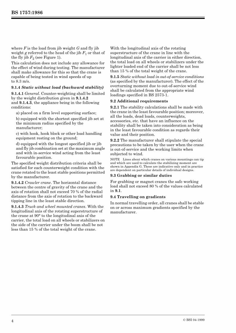
where F is the load from jib weight G and fly jib weight g referred to the head of the jib F1 or that of the fly jib F2 (see Figure 1).This calculation does not include any allowance for the effect of wind during testing. The manufacturer shall make allowance for this so that the crane is capable of being tested in wind speeds of up to 8.3 m/s.
9.1.4 Static without load (backward stability)
9.1.4.1 General. Counter-weighting shall be limited by the weight distribution given in 9.1.4.2 and 9.1.4.3, the appliance being in the following conditions:
a) placed on a firm level supporting surface;b) equipped with the shortest specified jib set at the minimum radius specified by the manufacturer;c) with hook, hook block or other load handling equipment resting on the ground;d) equipped with the longest specified jib or jib and fly jib combination set at the maximum angle and with in-service wind acting from the least favourable position.
The specified weight distribution criteria shall be satisfied for each counterweight condition with the crane rotated to the least stable positions permitted by the manufacturer.9.1.4.2 Crawler crane. The horizontal distance between the centre of gravity of the crane and the axis of rotation shall not exceed 70 % of the radial distance from the axis of rotation to the backward tipping line in the least stable direction.9.1.4.3 Truck and wheel mounted cranes. With the longitudinal axis of the rotating superstructure of the crane at 90° to the longitudinal axis of the carrier, the total load on all wheels or stabilizers on the side of the carrier under the boom shall be not less than 15 % of the total weight of the crane.
With the longitudinal axis of the rotating superstructure of the crane in line with the longitudinal axis of the carrier in either direction, the total load on all wheels or stabilizers under the lighter loaded end of the carrier shall be not less than 15 % of the total weight of the crane.9.1.5 Static without load in out-of-service conditions (as specified by the manufacturer). The effect of the overturning moment due to out-of-service wind shall be calculated from the appropriate wind loadings specified in BS 2573-1.
9.2 Additional requirements
9.2.1 The stability calculations shall be made with the crane in the least favourable position; moreover, all the loads, dead loads, counterweights, accessories, etc. that have an influence on the stability shall be taken into consideration as being in the least favourable condition as regards their value and their position.9.2.2 The manufacturer shall stipulate the special precautions to be taken by the user when the crane is out-of-service and the working limits when subjected to wind.NOTE Lines about which cranes on various mountings can tip and which are used to calculate the stabilizing moment are shown in Appendix G. These are indicative only and in practice are dependent on particular details of individual designs.
9.3 Grabbing or similar duties
For grabbing or magnet cranes the safe working load shall not exceed 80 % of the values calculated in 9.1.
9.4 Travelling on gradients
In normal travelling order, all cranes shall be stable on or across maximum gradients specified by the manufacturer.

BS 1757:1986
© BSI 04-1999 5
Section 2. Structural
10 Frame structures including jibs: equivalent inertia forcesWith the exception of crawler cranes with a maximum safe working load of less than 30 t, for design purposes a side load of 2.5% of the safe working load shall be assumed to act at the jib head provided that the design of the slew gear is such that smooth varying rates of slewing acceleration and deceleration can be readily accomplished.For crawler cranes with a maximum safe working load of less than 30 t and for cranes where smooth operation of the slew gear cannot be accomplished, a side load of 6 % of the safe working load shall be assumed as acting at the jib head.
11 Joints11.1 Strength of joints
The calculated strength of riveted joints or joints made by friction grip bolts in structural members shall be not less than the calculated net strength of the member.The calculated strength of other bolted joints in structural members shall be not less than the net strength of the member plus 25 %.The calculated stress in rivets, bolts and welds shall not exceed the permissible stresses given in BS 2573-1.
11.2 Rivet and bolt holes (except those for friction grip bolts)
11.2.1 General. All rivet and bolt holes shall be drilled accurately and all arrises and burrs shall be removed before assembly.
Where bolts are used in shear, they shall be fitted into reamed holes. Black mild steel bolts shall not be used for joints in stress-bearing members.11.2.2 Friction grip bolts. Friction grip bolts shall comply with the requirements of BS 4395-1 and shall be fitted in accordance with the recommendations of BS 4604-1.11.2.3 Rivet spacing. The distance between the centres of rivets for stress-bearing parts shall be not less than 2.5 times the diameter of the rivet, and shall not exceed 16 times the thickness of the thinnest outside plate or angle. Where two lines of staggered riveting are used in the same angle or flange, the maximum distance between the rivets on each line can be taken as 1.5 times those given above.The distance between centres of rivets and the sheared or hand flame cut edge of a plate shall be not less than 1.75 times the diameter of the rivet, and between the centre of the rivet and a rolled, machined, or machine flame cut edge, shall be not less than 1.5 times the diameter of the rivet.
11.3 Welding
All welding shall comply with the requirements of BS 2573-1.

BS 1757:1986
6 © BSI 04-1999
Section 3. Mechanical
12 Steel wire ropes12.1 General
12.1.1 The selection of steel wire ropes shall be as specified in BS 2573-2, where relevant, for mobile crane service and shall comply specifically with the requirements of the following clauses.12.1.2 Where two or more ropes are used in a system, means shall be provided for ensuring that tensile forces in the ropes are distributed in the designed proportions. Arrangements entailing reverse bends shall be avoided as far as possible. A rope reeving diagram shall be provided.12.1.3 Derricking ropes shall be of sufficient length to permit the jib to be raised from, or lowered to, the horizontal position during the erection or inspection of the crane.
12.2 Coefficient of utilization
12.2.1 The coefficient of utilization of the rope shall comply with the following requirements for service and erection conditions.12.2.2 In determining the coefficient of utilization, allowance shall be made for friction losses at the pulleys, the safe working load of the crane (including lifting attachments such as slings, lifting beams, etc.) and the hook block, but excluding the weight of suspended rope. For grabbing or magnet cranes, the load shall be assumed to be the weight of the grab or magnet and its burden.12.2.3 Under service conditions, the coefficient of utilization for running ropes and standing ropes that pass over pulleys shall be not less than 4.5 for cranes to group classification A1, and 5.5 for cranes to group classification A3 and A4. For straight standing ropes, the ratio shall be not less than 3.5 for cranes to group classification A1, and 4.0 for cranes to group classifications A3 and A4.12.2.4 Under erection conditions, the coefficient of utilization for running ropes and standing ropes that pass over pulleys shall be not less than 3.75. For straight standing ropes, the coefficient of utilization shall be not less than 3.NOTE For the purpose of calculating friction losses, the efficiency of pulleys is assumed to be 98 % when fitted withanti-friction bearings and 96 % when fitted with plain bearings.
12.3 Fly jib pendent ropes
Where ropes are used to support a fixed offset fly jib, the distances between the support point centres shall be specified by the manufacturer to enable the fly jib offset to be correctly set under working conditions.
12.4 Rope termination
The rope termination (i.e. the terminal fitting together with the means of its attachment to the rope) shall be capable of withstanding not less than 80 % of the minimum breaking load of the rope.NOTE Recommended methods of attaching terminal fittings are given in appendices to each appropriate British Standard, e.g. Appendices A and B of BS 461:1970; Appendix A of BS 462:1983; Appendix B of BS 463-2:1970; Appendix A of BS 464:1958.
12.5 Rope anchorage to drum
Rope anchorages shall be protected by not less than two dead turns remaining on the drum when the rope is paid out to its maximum working length.Rope anchorages shall be secure and readily accessible. If two or more ropes lead off a drum, provision shall be made for adjustment of the rope length at the anchorage end.
13 Drums and rope reeving components13.1 General
13.1.1 Drums shall be either plain or grooved.13.1.2 Means shall be provided to prevent the rope inadvertently leaving the drum. The drum flanges shall project a distance of not less than two rope diameters beyond the outer layer of rope in all circumstances.NOTE A spur or other wheel secured to the drum can form one of the flanges provided it is adequately guarded.
13.1.3 The inclination of the rope at the point of a lead-off from the drum shall not exceed 1 in 12 each side of a centreline which represents the truelead-off.13.1.4 If a rope leads off against the helix angle of the drum grooving, care shall be taken to prevent the rope rubbing against an adjacent turn. In extreme cases the clearance between turns can be increased in order to meet this requirement.
13.2 Drum diameters
The minimum winding diameter of a plain drum or of a grooved drum measured at the rope centres shall be not less than 15 times the rope diameter, irrespective of the rope construction.
13.3 Drum groove
13.3.1 Grooving shall be smooth and free from surface defects liable to damage the rope. The edges shall be rounded.13.3.2 The contour at the bottom of the groove shall be circular over a minimum angle of 120°.13.3.3 The radius of the groove shall exceed the radius of the ropes by not less than the value given in Table 2.

BS 1757:1986
© BSI 04-1999 7
Table 2 — Minimum groove radii for rope drums and pulleys
13.3.4 The grooves shall be so pitched that the clearance between adjacent turns of rope is not less than the dimension given in Table 3.
Table 3 — Minimum rope clearances for drum grooves
13.3.5 If compensating links are used on the free or returned ends of two parts of rope to equalize the load, the drum grooves shall be of identical diameters to ensure that the two parts of the rope wind equally, and the difference in the length of the ends of rope is maintained within the capacity of the compensating links throughout the full range of lift.
14 Lifting hooks14.1 Lifting hooks shall comply with the requirements of BS 2903 or BS 3017, as applicable.Hooks complying with the requirements of BS 2903 shall be provided with an efficient device to prevent the displacement of the sling or the load from the hook.14.2 Swivelling hooks shall be mounted onanti-friction bearings suitable for the purpose.If required, a locking device shall be fitted to prevent rotation of the hook.
15 ShacklesShackles shall comply as regards strength and safety with the requirements of BS 3032 or BS 3551. Shackles used for attaching the hook shall be provided with screwed pins. Slotted heads in countersunk screwed pins are not recommended.
16 Overhauling weightIf an overhauling weight is used on the rope, it shall have a smooth hole and be bell-mouthed at the top and bottom to accommodate and prevent damage to the rope and rope termination. Provision shall be made for the examination of the part of the rope passing through the weight.The overhauling weight shall be designed so as to avoid catching on obstructions.
17 Rope pulleys17.1 Pulley diameters
The diameter of rope pulleys at the rope centres shall be not less than 18 times the rope diameter. Compensating pulley diameters shall be not less than 15 times the rope diameter.
17.2 Pulley grooves
Rope pulleys shall be grooved to a depth not less than 1.5 times the diameter of the rope. The grooves shall be finished smoothly and shall be free from surface defects liable to damage the rope. The edges shall be rounded.The contour at the bottom of the groove shall be circular over an angle of not less than 120°. The radius of the groove shall comply with the requirements of 13.3.3.The included angle of flare of the sides of the pulley groove shall be a maximum of 60° for an angle of lead of 1 in 12.NOTE The angle of flare may be reduced for smaller angles of lead provided that the flange does not interfere with the rope.
17.3 Angle of lead (or fleet angle)
The angle of lead between the rope and a plane perpendicular to the axis of the pulley shall not exceed 1 in 12.
17.4 Guarding
Provision shall be made to retain the rope in the groove.
17.5 Supports
Suitably designed supports shall be fitted, where necessary, on the jib and other parts of the structure to prevent chafing of the ropes.
18 GearingGearing shall be in accordance with BS 2573-2.
19 Rotating and fixed shafts and axlesRotating and fixed shafts and axles shall be in accordance with BS 2573-2.
Nominal diameter of rope (d) Minimum amount by which groove
radius shall exceed rope radius
mm mm
Up to and including 16Over 16 up to and including 26Over 26 up to and including 28Over 28
0.81.21.62.4
Nominal diameter of rope (d) Minimum clearance between
turns
mm mm
Up to and including 13Over 13 up to and including 28Over 28
1.62.43.2

BS 1757:1986
8 © BSI 04-1999
20 Keys, keyways and splines20.1 Keys and keyways shall comply with the requirements of BS 4235.20.2 Splines shall comply with the requirements of BS 2059 or BS 3550.
21 Clutches21.1 General
Clutches shall be designed to transmit the maximum torque for the motion for all conditions of usage.
21.2 Sprag clutches
When sprag type clutches are used in hoist and derricking systems, they shall incorporate a positive mechanical lock against failure or be designed to transmit twice the maximum torque imposed by the maximum line pull.
22 Brakes for crane motions22.1 General
22.1.1 Springs for applying brakes shall be of the compression type and shall not be stressed in excess of 80 % of the torsional elastic limit of the material.22.1.2 Brakes applied by hand shall not require a force greater than 108 N (25 lbf) at the handle. If applied by foot they shall not require a force greater than 314 N (70 lbf) on the pedal to exert the restraining torque specified in 22.2. All control levers and pedals shall be designed and positioned to take account of the requirements of clause 26.22.1.3 The wearing surfaces of all brake drums or plates shall be machined and shall be smooth and homogenous.22.1.4 Brake weights, if fitted, shall be positioned and fixed securely to their levers.22.1.5 Brake linings shall be adequately and permanently secure during their effective life.22.1.6 Brake blocks and linings shall be protected from rain, oil, grease or other environmental conditions.22.1.7 Brakes shall be provided with a simple and easily accessible device to compensate for the wear of the linings. This device shall be self-compensating whenever practicable.22.1.8 Brakes for securing a hoist or derricking motion shall be held in the applied position by a positive actuating device. Brake mechanisms that rely upon air or fluid under pressure or an electrical mechanism for application shall be supported by an additional positive mechanical mechanism.
22.1.9 For electro-mechanical brakes, energization of the brake magnet due to back e.m.f. of the motor shall be prevented by the control gear in the “off” position isolating the brake magnet, after tripping of the overtravel limit or other appropriate protective device.22.1.10 If electric braking is adopted, the conductors and contact surface of the motor and the control gear shall be proportioned so that the additional duty will not cause overheating (see 32.5).
22.2 Individual brake motions
22.2.1 General. Means shall be provided for arresting each motion of the crane, and if controlled by a brake, the following minimum requirements shall apply.22.2.2 Hoisting motion brakes. Hoisting motion brakes shall be designed to exert a restraining torque at least 25 % greater than the maximum torque transmitted to the brake drum from the suspended load under service conditions. In estimating this torque, the effects of friction in the transmission system between the load and the brake shall be ignored.If free lowering is possible, the temperature of the friction surfaces of the brake shall not exceed the maximum working temperature specified by the manufacturer of the brake linings, after the maximum safe working load has been raised and lowered on the brake five times without pause through the specified height of lift.22.2.3 Derricking motion brakes. For cranes with a derricking motion operated by rope and drum system, the brake shall be designed to exert a restraining torque at least 25 % greater than the maximum torque transmitted to the brake drum from the suspended load under service or erection conditions, whichever is the greater. In estimating this torque, the effects of friction on the transmission system between the load and the brake shall be ignored.The main derricking motion brake shall be automatically applied when the derricking control lever is moved to the “off” or “neutral” position.22.2.4 Cranes with derricking jibs. On cranes having a derricking jib operated through a clutch with the exception of those noted below in a) and b), an effective interlocking arrangement shall be provided between the derricking clutch and the pawl sustaining the derricking drum. Theinter-locking arrangement shall ensure that the clutch cannot be disengaged unless the pawl is in effective engagement with the derricking drum, and the pawl cannot be disengaged unless the clutch is in effective engagement with the derricking drum.

BS 1757:1986
© BSI 04-1999 9
NOTE This need not apply to any crane in which: a) the hoisting drum and derricking drum are independently driven;b) the mechanism driving the drum is self-locking.
22.2.5 Slewing motion brakes
22.2.5.1 Slewing brakes. Except when the slewing motion is controlled by reversing clutches, an effective slewing brake shall be provided, designed to exert an adequate restraining torque which will not subject the jib to a deceleration greater than that for which it is designed.22.2.5.2 Slewing holding brakes. If restraint is applied by a slewing clutch, a holding brake, capable of preventing movement of the superstructure under service conditions, shall be fitted.22.2.5.3 Slewing lock. A positive lock or sprag shall be provided to retain the superstructure in a fixed position.22.2.6 Travelling brakes. Effective travelling and parking brakes shall be fitted, capable of securing the unloaded crane on a slope of not less than that on which the machine is designed to travel and in no case shall this be less than 10 %. This shall be achieved without the use of chocks.Where the vehicle is subject to road traffic regulations, the conditions specified for brakes in those regulations shall apply.
23 LubricationAll bearings shall be adequately lubricated. Plain bearings or their shafts shall have oil or grease grooves. All lubrication nipples should be of similar size and type and shall be readily accessible.Where access for lubrication is difficult, bearings shall be such that lubrication is required as infrequently as possible or facilities for lubrication from a remote position shall be provided.Lubricating nipples shall comply with the requirements of BS 1486.A lubrication diagram shall be provided.
24 SlewingFor cranes on which the slewing motion is power operated, the slewing mechanism shall be so designed that it is not damaged due to fierce acceleration, braking or reversal of motion.The mechanism shall be designed to withstand the forces specified in clause 10.
In the case of proprietary slewing rings, it is particularly important that the manufacturer is consulted and given full details of the loads and duty involved. Attention shall be given to the method of mounting and the bolting requirements for which the manufacturer’s recommendations shall be taken into account.
25 Guarding25.1 All gear wheels, pinions and chain drives shall be completely encased unless such parts are so situated in relation to the structure of the crane as to be as safe as if complete encasement were provided.25.2 Effective guards shall be provided for revolving shafts and couplings unless every set screw, bolt or key on any revolving shaft is sunk, shrouded, or otherwise effectively guarded.25.3 All other dangerous parts of the machine shall be guarded in accordance with BS 5304.
26 Controls26.1 Control positions and markings
Operating levers or wheels shall have clear markings, on or adjacent to them, to indicate their function and mode of operation.If the design of a crane is such that the effect of the steering wheel or any other motion is reversed when the jib is slewed through 180°, an appropriate notice or other indication clearly drawing attention to this shall be provided.NOTE 1 Where motions can be reversed it is recommended that self-correcting controls are incorporated.NOTE 2 All practical measures should be taken to prevent accidental movement of controls.NOTE 3 All controls should be placed in a position in accordance with best ergonomic practice with control levers and pedals placed in such positions as to allow the driver/operator, when in his normal position, ample room for operation, as far as possible an unrestricted view of the load and as clear a view as possible of the immediate surroundings, both forward and to each side of that position.
26.2 Motion controls
Control arrangements can be specifically designed for “joy-stick” control of two movements simultaneously, otherwise they shall be so designed that selection of one movement cannot cause any other movement unless it is for the operation of a safety device or interlock.Control valve systems shall be designed to return to the neutral position when released, except when operational characteristics dictate otherwise.

BS 1757:1986
10 © BSI 04-1999
27 Manual operationArrangements for any operation relying wholly on manual effort (i.e. without power assistance) shall be such that an operator turning a handle, a wheel, or pulling a lever shall not be required to exert a mean force in excess of 108 N (25 lbf) continuously or 177 N (40 lbf) as a maximum at a mean speed of 46 m/min (150 ft/min).
28 Crane driver’s stationExcept for lorry loaders or unless stated to the contrary by the purchaser, a cabin shall be supplied by the manufacturer. The cabin shall:
a) afford the driver protection from the weather;b) be fitted with safety glass complying with the requirements of BS 5282;c) have a lock fitted to the door to prevent unauthorized entry when the crane is left unattached;d) have a securely fixed adjustable seat for the driver;e) be provided with a heater to satisfy statutory requirements;f) be provided with a means of ventilation;g) have either natural or artificial illumination to ensure that all charts and instruments are visible to the driver;h) have safe access to the driver’s cabin.
NOTE 1 The driver should as far as is practicable be provided with a clear and unrestricted view of the load and the jib in all normal working positions and as clear a view as possible of the extremity of any forward projection and of the road ahead when the crane is travelling.NOTE 2 Guidance for the recommended driver’s cabin envelope is given in BS 5538.
29 Internal combustion engines29.1 Internal combustion engines shall comply with the requirements of BS 5514 and a silencer shall be fitted to the exhaust. The exhaust shall not discharge in such a manner as to cause danger or discomfort to the driver or to any person in the vicinity.NOTE Where practicable the exhaust from an engine should be discharged vertically as high as possible, and it is recommended that means should be provided to prevent the ingress of water into the exhaust system.
29.2 Fuel tank capacity shall be sufficient for at least 8 h running on normal crane duty, and means shall be provided for ascertaining the quantity of fuel contained in the tank.29.3 The sump and lubricating system of the engine shall be so arranged that efficient lubrication is maintained in all planes of operation covered by the specification both during travelling and lifting operations.29.4 Provision shall be made where necessary for draining the water circulating system during frosty weather, the drain cocks being fitted in accessible positions. The arrangement shall be such that it is not possible to leave pockets of water in either the system or the pump casing.
30 Pneumatic tyres30.1 The crane shall be fitted with tyres that comply with the crane manufacturer’s specification.30.2 The crane shall have a legible and prominent inscription on the chassis giving the correct inflation pressure of the tyres.
BS 1757:1986
© BSI 04-1999 11
Section 4. Electrical
31 Electric motors and generators31.1 Specification and rating
Motors and generators shall comply with the requirements of BS 4999 and BS 5000 and shall be suitable for operating on the appropriate a.c. or d.c. circuit. The ratings and enclosures shall be such that, under the specified service ambient or altitude conditions, the temperature rise will not exceed the limits stated in the above standards for the class of insulation employed.
31.2 Limiting speed
Crane motion motors shall be capable of withstanding a maximum speed of 2.5 times the rated speed.
31.3 Design and construction
If required by the duty, motors shall be suitable for reversing and frequent acceleration. If it is intended to retard or stop the motion of a crane by electric braking, the motor and its control gear shall be of suitable design to withstand this duty.
31.4 Mounting
Motors and generators shall be so located on the crane that access to brush gear and terminals for inspection and maintenance and normal ventilation are not restricted.
32 Control gear32.1 Type
Control gear can be of the electrical-mechanical type (e.g. controllers and resistors), or solid state (e.g. thyristor) or a combination of both. The equipment shall comply, so far as is reasonably practicable, with the requirements of BS 5486-1 and the Institution of Electrical Engineers (IEE) Wiring Regulations currently in force.NOTE For further information see CP 1011, CP 1016 and BS 5304.
32.2 Enclosures
Control gear shall provide protection against accidental contact with live parts not less than IP4 in accordance with BS 5420 and BS 5486-1. Ventilated enclosures for line resistors shall provide a degree of protection against ingress of foreign bodies not less than IP3. Where equipment is mounted outside, weather protection shall be provided in accordance with BS 5486-1. The second characteristic numeral shall be not less than 3.
32.3 Rating
Control gear and resistors shall be rated so that the temperature does not exceed the limit specified in BS 5486-1, during the operation of the crane under service conditions.
32.4 Controller “off” position
Controllers when in the “neutral” or “off” position, shall open all supply lines of the respective motors unless otherwise agreed between the purchaser and the manufacturer in which case a warning notice shall be fixed to the controllers.
32.5 Electric braking
If electric braking is incorporated, the conductors and contact surfaces of the motor and control gear shall be proportioned to cope with this duty.
32.6 Servo controls
Servo controls of electro-pneumatic orelectro-hydraulic type, whether used as fundamental operator controls or auxiliary control mechanisms, shall be suitable for the operational duty.
33 Protective gear33.1 Source of supply
Where the power supply to the motion motors is generated on the crane, such protective gear shall be fitted as is necessary to avoid danger and to prevent harmful overloading of the prime mover and electrical equipment.Where the power supply to the crane is obtained from a distribution point on an external supply main, suitable metal enclosed electrical protective gear shall be provided, and a main isolating switch shall be fitted in a prominent position either in the cab, or adjacent to it, capable of cutting off the supply for all power-driven and associated equipment on the crane. The isolating switch shall be clearly marked. In addition, monitored earth leakage protection in accordance with BS 4444 shall be used for cranes supplied at mains voltage, through trailing cables, coiled extensible cords or from cable reels.NOTE For further information see CP 1017.
33.2 Control equipment
Circuit-breakers, contactors, relays and similar control equipment shall be of sound construction, adequate for the duty concerned, and shall comply with the requirements of the relevant British Standards.Electrical, and where practical mechanical, interlocking shall be incorporated to prevent closure of the main circuit-breaker or contactor unless the control gear for all individual subsidiary circuits is in the “open” or “neutral” position.

BS 1757:1986
12 © BSI 04-1999
A push-button emergency stop or stops, placed readily available for prompt use by the operator in emergency, shall be connected either in the operating coil circuit of the main contactor or in the undert-voltage release circuit of the maincircuit-breaker, as appropriate.All fuses, except for local low current control circuits, shall be of HR cartridge type complying with the requirements of the British Standard appropriate to the application.
34 Fixed cables, wiring and other conductors34.1 General
Cables shall comply with the requirements of BS 6007, BS 6231 or BS 6004.
34.2 Minimum size
Cables having conductors with a sectional area smaller than 2.5 mm2 shall not be used for the power wiring to any of the motors. For control circuits and auxiliary wiring, cables having a sectional area smaller than 1 mm2 shall not be used.
34.3 Protection
All cables shall be adequately protected against mechanical damage and metal trunking can be used if desired. If electric conduit is used, it shall comply with the requirements of BS 31 or BS 4568; PVC or similar conduit shall not be used.All cables and the method of wiring shall comply with the IEE Regulations for the Electrical Equipment of Buildings, currently in force.NOTE Attention is also drawn to BS 5486-1, where applicable.
35 Cables for cable reels and similar applications35.1 Minimum bending radius
The minimum radius for cable drums and supports shall be not less than that recommended by the cable manufacturer.
35.2 Coiled extensible cords
Coiled extensible cords shall be of suitable quality. They shall not be used in situations where they are liable to be fouled and shall be adequately supported.
35.3 Magnet cables
The main cable shall normally be connected to a spring loaded or counter-balanced drum which shall comply with the requirements of 35.1.Means shall be provided to limit rotation of the crane hook.NOTE Care should be taken to ensure that trailing cables used in conjunction with self-winding cable drums are anchored in such a manner as to prevent the tension from the drum being transmitted to the connector, e.g. by means of a cable clamp and chain or trunnion.
36 Trailing cablesTrailing cables, where used, shall comply with the requirements of BS 6116 or BS 6708 in respect of insulation, mechanical strength and construction.
37 Cable ratingsThe ratings of all cables shall comply with those shown in the relevant tables of the IEE Regulations for the Electrical Equipment of Buildings currently in force. When cables are reeled on a drum, their rating shall be reduced to take account of the heating effect.NOTE For cranes with a group classification of A1 and equipped with 30 min or 60 min rated motors and working under average conditions, these ratings may be increased by factors of up to 1.7 and 1.4 respectively.
38 Wiring diagramA wiring diagram, or a circuit diagram, or both, incorporating full details of all main and control circuits shall be provided in the manufacturer’s handbook.
39 LightingLighting shall be provided as required by the purchaser. Travelling lights shall comply with road vehicle lighting regulations, where applicable.
40 Radio interferenceIf necessary, provision shall be made to prevent engines or electrical equipment giving rise to radio interference. This provision shall be in accordance with BS 800 and BS 833.

BS 1757:1986
© BSI 04-1999 13
Section 5. Hydraulic equipment
41 General requirements41.1 Filtration of fluid
Provision shall be made in the installation for filtration of the working fluid and for protection of the fluid against pollution.
41.2 Safe hydraulic pressure
The raising of the pressure at any point to a value above the safe maximum, due to any effect whatsoever, shall be prevented by positive means.
41.3 Back pressure
Back pressures which can affect the safety of the crane shall be prevented or relieved.
41.4 Safety of the appliance and load
Means shall be provided in the hydraulic circuits to protect the appliance and load against:
a) for all cranes:1) a gravity fall of the load in the event of hydraulic failure;2) hydraulic shock caused by the sudden closure of any control valve leading to over-running of the associated motion;3) loss of oil supply pressure;4) the effect of hose burst;5) runaway of the load in the event of a load reversal;6) the collapse of stabilizers/outriggers under load;
b) for lorry loaders only: an overload being lifted.NOTE 1 For both a) and b) any valves in the pressure lines to the actuators should be as close coupled to the actuators as practicable.NOTE 2 In the case of a) 1), 3) and 4) a restrictor may be provided to permit a slow descent of the load. Some pilot operated valves are suitable and may be fitted as an alternative.
41.5 Controls
The circuit and control arrangement shall be such that no combination of control selections in one circuit can cause in any other circuit a movement not intended by the operator, unless this is essential for the operation of a safety device or interlock.
41.6 Motion drives
Provision shall be made to prevent the load from driving hydraulic motors beyond their specified limits.
Hydraulically powered motions shall not allow unintentional movement.
41.7 Circuit diagram
A hydraulic circuit diagram shall be provided in the manufacturer’s handbook.
42 Power transmission42.1 Safety devices
The system shall be so designed as to fail safe.
42.2 Installation
The installation of the hydraulic system shall be such that as far as possible the effects of external influences (such as atmospheric conditions, unauthorized interference, mechanical impact, fretting and chafing of pipes, etc.) shall not be detrimental to the system. In addition, installation stresses in the tubes shall be avoided and flexibility of the supporting members shall be allowed for on all rigid tubes. Tubes and hoses shall not be bent to radii smaller than those specified by the manufacturer.
42.3 Speed of flow
Cavitation and back pressure shall be avoided by the use of suitable speeds of fluid in tubing and components.Tubes, hoses, connectors and unions shall be dimensioned with due consideration for the pressure and rate of fluid flow in them, and the resistance they are likely to cause.
42.4 Temperature of fluid
A cooler shall be fitted, if required, to keep the temperature of the fluid within the limits specified by the fluid supplier.
42.5 Fluid reserve
Tanks shall have a sufficient capacity to ensure an uninterrupted flow of fluid to all rotating machinery whilst working, and (in those cases where no other cooling device is fitted) hold a sufficient reserve of fluid to keep the temperature within the limits specified by the supplier and to minimize cavitation. A ready means of ascertaining that the fluid is within the normal working level shall be provided.NOTE For further information see BS 4575-1.

BS 1757:1986
14 © BSI 04-1999
Section 6. Pneumatic equipment
43 General requirementsThe equipment shall not be subjected to speeds, loads, pressures or temperatures in excess of those specified by the equipment manufacturers.Connectors, unions and pipes shall be dimensioned so as not to restrict flow of air through them.Equipment shall be protected against ingress of dirt and moisture.Provision shall be made for filtration of air entering the system.Equipment requiring regular maintenance shall be placed in an accessible position.A pneumatic circuit diagram shall be provided in the manufacturer’s handbook.
44 Application44.1 Safety devices
Safety valves shall be fitted to prevent overpressurizing of the system.NOTE The system should, as far as reasonably practicable, be designed to fail safe.
44.2 Installation
The installation of the pneumatic system shall be so arranged that the effects of external influences, e.g. atmospheric conditions, unauthorized interference, impact or vibration shall not be detrimental to the system, and installation stresses in the pipes shall be avoided.
Air from valves shall not exhaust inside the driver’s cab.
44.3 Air supply
The compressor shall be rated to supply the necessary quantity of air for the equipment concerned which shall be temperature cooled before passing into the control system. If the control system and the crane travelling braking system have a common source of air supply, operation of or leakage in the control system shall not adversely affect the performance of the braking system.A gauge indicating air receiver pressure shall be supplied. Air receivers shall be constructed, tested and identified according to the appropriate British Standard (see BS 3256 or BS 5169).Air receivers shall be located in such a position as to facilitate statutory inspection and test.A means of draining accumulated condensate from the air receivers shall be provided together with an air line filter and water trap situated before the control valves.When industrial alcohols are being used in air systems, a warning of possible danger shall be included in the instruction manual.

BS 1757:1986
© BSI 04-1999 15
Section 7. Safety
45 Safe working load charts45.1 General
Charts showing the safe working loads for the various specified operating conditions shall be displayed in a position clearly visible to the driver.Any limitations of the operating conditions for safety reasons, e.g. minimum radius, etc., shall be clearly specified on the charts.If a crane is to be used for grabbing or magnet duties, the safe working load chart shall take into account any derating which may be necessary as specified in 6.2.The safe working load shall include the weight of the hook block or any other load handling attachments such as slings, equalizing beams and other similar devices. The chart shall also show the maximum radius or minimum jib angle at which the crane can be operated when working with the grab or magnet.To warn drivers of unstable conditions the safe working load charts shall state the maximum and minimum allowed radii of the unloaded jib, in the blocked and/or unblocked condition.A typical safe working load chart for a lorry loader is shown in Figure 10.NOTE 1 Safe working loads should preferably be specified in terms of load and radius at which that load may be lifted. (For hydraulic excavators used as cranes it will be necessary to specify in addition the height of the lifting attachment above or below ground level.) In special circumstances (i.e. attachments used on the end of telescopic jibs) it may be necessary to specify safe working loads in terms of jib angle.NOTE 2 Care should be taken with the terms “load moment” and “Tonne-metre” because the products of safe working loads and radii at which they may be lifted will never be constant throughout the operating range of a crane. A load moment rating will only be correct for one particular radius and cannot be used to obtain the safe working load at another radius. The table in Figure 10 shows how the load moment for a typical lorry loader will vary with radius.
45.2 Telescopic cranes
On telescopic cranes where the operating instructions permit operation of the crane at intermediate jib lengths (i.e. between those specified on the duty chart) and the chart is annotated accordingly, the safe working load shall be as follows.
a) Stepped duties. Where at any given radius the safe working load remains constant at the intermediate jib lengths, the jib length on the duty chart shall be as stated as from one specified length to the next specified length (see Figure 11).b) Interpolated duties. Where at any given radius the safe working load has to be interpolated at the intermediate jib lengths, the jib length on the duty chart shall be specified as a finite length (see Figure 12).
46 Marking of hook and block weightsThe weight of the hook(s)/block(s) shall be clearly and durably marked on them.
47 Marking of outrigger beamsOutrigger beams shall be clearly and durably marked to show when they are fully extended.When the manufacturer of the crane has specified intermediate extension of the outriggers the following conditions shall be fulfilled:
a) the intermediate extension positions shall be clearly and durably marked;b) the manufacturer shall provide a test certificate indicating the correct safe working loads applicable to the relevant outrigger extensions;c) the duty chart shall give the specified intermediate extension;d) provisions shall be made in the automatic safe load indicator, if fitted, to accommodate the specified intermediate extension.
48 Lattice strut jib connectionsThe connections between the sections of lattice strut jibs and sections of fly jibs shall be designed so that they can only be disconnected by an operator standing out from under the section. This may be achieved by the use of pins which can only be inserted from inside the jib so that an operator must stand outside of the jib to drive them out.
49 Radius/jib angle indicatorsExcept for articulated jib cranes and cranes having a constant safe working load the crane shall be fitted with a radius or jib angle indicator marked according to the safe working load chart.These indicators shall be clearly visible from the driver’s operating position.
50 Safe load indicatorWhere an automatic safe load indicator is fitted it shall warn the operator, by visible and audible means of approach to the safe working load, and shall give visible and audible warning when an overload occurs.NOTE Where the crane is used under certain regulations the safe load indicator should be of a type that is approved by HM Chief Inspector of Factories.
51 Travelling with suspended loadsA clear statement of any limitations of the crane with regard to travelling with suspended loads shall be given in the manufacturer’s specification and in the operators handbook.

BS 1757:1986
16 © BSI 04-1999
Where travelling with a suspended load is permitted this shall be clearly and durably marked on the crane with the relevant safe working loads.
52 Audible warning deviceA device shall be fitted to enable the driver of aself-propelled crane to give audible warning of approach.
53 Motion limitsPrecautions shall be taken to prevent overhoisting and overderricking by limit switches or other suitable means.Where the safe working load charts state that the arc of slewing is limited, suitable means shall be provided to warn the driver of approach to the limit of arc of slewing unless the limit of slew is set by stops.NOTE Where a positive overload prevention device is fitted there should be no inhibition to reversing movement of the load at any time, thereby allowing a retreat from the potential overload position.
54 Level indicatorCranes (with the exception of those on pneumatic tyres or other flexible mountings) shall be fitted with a level indicator that will enable the level of the crane to be clearly established within an accuracy of ± 5 % of the specified level (see 6.1).
NOTE Cranes on pneumatic tyres or any other flexible mounting require a different technique to establish that they are in a suitable condition for operation.
55 AnemometerWhen required by 6.2 or for jibs or jib combinations with a length in excess of 65 m, an anemometer or wind speed measuring device shall be provided at a suitably elevated position on all mobile cranes. The indicator of the instrument shall be fitted in a position where it can be clearly seen by the operator from his position in the cabin.
56 Danger of overhead power cablesA suitable plate shall be fixed in the driver’s station or stations warning of the danger of overhead cables.NOTE For further information see CP 3010.
57 Instruction bookAn instruction book shall be provided with each crane and shall include adequate information to enable safe use including erection, dismantling and operation of the crane.

BS 1757:1986
© BSI 04-1999 17
Section 8. Testing
58 General58.1 The aim of testing is to demonstrate that the crane conforms to the requirements stipulated by the specification and to verify the behaviour of component parts. When conducting acceptance tests, the manufacturer shall be entitled to employ his own driver.58.2 The tests shall be the responsibility of the manufacturer and shall be carried out at the manufacturer’s works or at a place to be agreed between the purchaser and the manufacturer. Additional tests may be carried out subject to agreement between the manufacturer and purchaser.58.3 All tests shall be carried out on a firm and level surface (± 0.5 % slope) during weather conditions in which the wind speed does not exceed 8.3 m/s. Tyres, where fitted, shall be inflated to pressures specified by the manufacturer for normal crane duties.58.4 When testing blocked crane duties, outriggers shall be extended in accordance with the manufacturer’s instructions. Outrigger jacks shall not be used when testing free on wheels/crawler duties.58.5 The manufacturer shall clearly indicate whether or not the hook block is to be considered as part of the test load.58.6 The weight of slings, equalizing beams and other similar devices for handling test loads shall be taken as part of the test load.
59 Tests to be carried out59.1 Functional tests
The operational functions of the complete crane shall be tested with no load to demonstrate the following.
a) The satisfactory operation of each control device and, where fitted, each cut-out device for overhoisting, overlowering, overslewing and overderricking.
b) The satisfactory operation of each crane motion at the specified unladen operating speeds or times.
59.2 Static overload tests
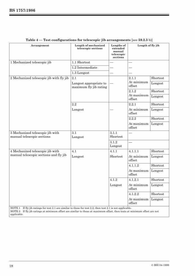
59.2.1 Static overload tests shall be conducted for the purpose of demonstrating the structural competence of the crane and its components.59.2.2 Static overload tests shall be performed separately for each hoisting mechanism and for concurrent operation of hoisting mechanisms, if permitted by the crane specification, in such positions and configurations as will impose maximum rope loads, maximum bending moments and/or maximum axial forces, as applicable, in the major crane components and anchorages.59.2.3 For cranes other than lorry loaders, where such positions and configurations cannot be identified, the tests detailed below shall be carried out.
a) Tests shall be carried out for all lengths of jibs and also, where applicable, for all lengths and configurations of jib with fly jib, mast/tower with jib and mast/tower with jib and fly jib.b) In the case of subsequent production cranes, tests shall be carried out for all applicable lengths and configurations of jib, jib with fly jib, mast/tower with jib and mast/tower with jib and fly jib as specified in Table 4, Table 5 and Table 6, commensurate with the equipment ordered by the purchaser. The tests shall be carried out at maximum radius or lowest jib angle and at the appropriate radius or jib angle for the maximum safe working load for the particular configuration under test.
BS 1757:1986
18 © BSI 04-1999
Table 4 — Test configurations for telescopic jib arrangements [see 59.2.3 b)]
Arrangement Length of mechanized telescopic sections
Lengths of extended manual
telescopic sections
Length of fly jib
1 Mechanized telescopic jib 1.1 Shortest — —
1.2 Intermediate — —
1.3 Longest — —
2 Mechanized telescopic jib with fly jib 2.1 2.1.1At minimum offset
Shortest
Longest appropriate to maximum fly jib rating
— Longest
2.1.2At maximum offset
Shortest
Longest
2.2 2.2.1 Shortest
Longest — At minimum offset
Longest
2.2.2 Shortest
At maximum offset
Longest
3 Mechanized telescopic jib with manual telescopic sections
3.1Longest
3.1.1 Shortest
—
3.1.2 Longest
—
4 Mechanized telescopic jib with manual telescopic sections and fly jib
4.1 4.1.1 4.1.1.1 Shortest
Longest Shortest At minimum offset
Longest
4.1.1.2 Shortest
At maximum offset
Longest
4.1.2 4.1.2.1 Shortest
Longest At minimum offset
Longest
4.1.2.2 Shortest
At maximum offset
Longest
NOTE 1 If fly jib ratings for test 2.1 are similar to those for test 2.2, then test 2.1 is not applicable.NOTE 2 If fly jib ratings at minimum offset are similar to those at maximum offset, then tests at minimum offset are not applicable.

BS 1757:1986
© BSI 04-1999 19
Table 5 — Test configurations for strut jib arrangements [see 59.2.3 b)]
Table 6 — Test configurations for mast/tower and jib arrangements [see 59.2.3 b)]
59.2.4 For lorry loaders the tests shall be carried out at the radii given in Table 7.To enable this test to be carried out on a lorry loader the relief valve system and the positive overload protection device (where fitted) shall be overridden or disconnected. At each radius the load shall be slewed slowly through the full slewing arc possible in service. Where alternative hook positions are provided they shall be tested to their safe working loads.CAUTIONARY NOTE. Where safety devices have been overridden or disconnected care should be taken to ensure that these are reconnected and, where appropriate, are reset and retested before the machine is released from testing.
59.2.5 The static overload test load shall be 1.25p, where p is the safe working load as defined in 2.17.The test load shall be lifted 100 mm to 200 mm from the ground and suspended for a period necessary for the test but not less than 10 min.
59.3 Static overload test criteria
The crane shall be considered to have passed the tests in clauses 58 and 59.1 to 59.2.5 if no crack, permanent deformation, paint flaking or damage which affects the function and safety of the crane is visible and no connection or anchorage has loosened or been damaged.Table 7 — Test configurations for articulating
jib cranes (see 59.2.4)
59.4 Testing of indicators
59.4.1 The settings and satisfactory operation of the automatic safe load indicator, if fitted, shall be confirmed during the course of the test procedure.59.4.2 The settings and satisfactory operation of the radius and/or jib angle indicator, if fitted, shall be confirmed during the course of the test procedure.
59.5 Stability test
59.5.1 General. A stability test shall be carried out to demonstrate that the crane complies with the requirements of clause 9.The tests shall be carried out in those positions or configurations of minimum stability. If different loads are specified for different arcs or working areas, tests shall be carried out to check the stability for such conditions.
Arrangement Jib length Fly jib length
1 Jib 1.1 Shortest —
1.2 Intermediate
—
1.3 Longest —
2 Jib with fly jib
2.1Longest appropriate to maximum fly jib ratings
2.1.1At minimum offset
Shortest
Longest
2.1.2At maximum offset
Shortest
Longest
2.2Longest
2.2.1At minimum offset
Shortest
Longest
2.2.2At maximum offset
Shortest
Longest
NOTE 1 If fly jib ratings for test 2.1 are similar to those for test 2.2, then test 2.1 is not applicable.NOTE 2 If fly jib ratings at minimum offset are similar to those at maximum offset, the test at minimum offset is not applicable.
Arrangement Length of mast/tower
Lengths of jib (telescopic or strut)
and fly jib
1 Mast/tower with jib
1.1 Shortest
As Table 4 or Table 5
1.2 Longest
As Table 4 or Table 5
2 Mast/tower with jib and fly jib
2.1 Shortest
As Table 4 or Table 5
2.2 Longest
As Table 4 or Table 5
Arrangement Radius
1 Articulating jib 1.1 Maximum obtainable
1.2 For the maximum safe working load
2 Articulating jib plus telescopic sections (powered or manual but not both)
2.1 Maximum obtainable
2.2 Maximum obtainable with sections retracted
2.3 For the maximum safe working load
3 Articulating jib plus powered and manual telescoping sections
3.1 Maximum obtainable
3.2 Maximum obtainable with manual sections retracted
3.3 Maximum obtainable with manual and powered sections retracted
3.4 For the maximum safe working load

BS 1757:1986
20 © BSI 04-1999
To compensate for tyre and other deflections when a load is applied, the radius shall be adjusted to the appropriate rated working radius measured at ground level.NOTE 1 See Appendix G Figure 14 and Figure 15 for typical tipping lines for stability testing.NOTE 2 The stability test need not be repeated on subsequent machines of an identical type except when agreed between the manufacturer and the purchaser.
The manufacturer shall provide information relating to minimum stability when requested.
59.5.2 For cranes other than articulated jib cranes and cargo handling cranes the test load used shall be determined according to the following formulae.
where (see Figure 1)
Figure 1 — Elevation of typical jib configuration
Tk = 1.25p + 0.1F (1)
F is the load from jib weight G and fly jib weight g referred to the head of the jib F1 or that of the fly jib F2
X, Y, x, y are the coordinates of centres of gravity for jib and fly jib
j, k are the dimensions for jib and fly jibm, n are the radii of centres of gravity for jib
and fly jibp is the safe working load

BS 1757:1986
© BSI 04-1999 21
The manufacturer shall supply the value of F where requested by the purchaser.The following is an example of the calculation of F using the designations shown in Figure 1.
NOTE 1 Where testing a crane with fixed jib, equation (1) becomes Tk = 1.25p.NOTE 2 When testing a jib crane equipped with a fly jib and the load is lifted by the main hoisting mechanism, in equation (2) k = 0.NOTE 3 If requested by the customer, values of p, G and g as well as locations of G and g should be provided by the manufacturer in the crane documentation for each length of jib and fly jib.
59.5.3 Cargo handling cranesFor cargo handling cranes the test load shall be:
a) 1.33p where the crane is on outriggers or crawler tracks; orb) 1.5p where the crane is free on wheels.
59.5.4 Articulated jib cranes (e.g. excavators used as cranes and lorry loaders)59.5.4.1 General. Stability shall be demonstrated by applying a test load of 1.4p or, alternatively, by calculation in accordance with 59.5.4.2 or by a weighbridge test in accordance with 59.5.4.3.59.5.4.2 Stability verification by calculation. A total overturning moment calculation shall be based on:
a) safe working load at the maximum radius attainable with hydraulic out reach;b) no load on the load carrying platform of the vehicle in the case of lorry loaders;c) jib fully extended at right angles to the tipping line;d) the most adverse combination of the least distance of the vehicle and crane centres of gravity behind the tipping line with the greatest distance of the applied load forward of the tipping line.
The righting moment shall be not less than 1.4 times the overturning moment but where the value calculated falls between 1.4 and 1.5 the vehicle axis weights shall be verified on a certified weighbridge as being not less than those used in the calculation.NOTE See Appendix E for information necessary to make the calculation and an example. See also Figure 2.
59.5.4.3 Weighbridge test. The crane shall be positioned over a weighbridge as follows.
a) The tipping line about which the crane would overturn in the least stable conditions shall be ascertained.
b) The crane shall be positioned with the jib extended to the condition to be tested, so that all parts of the crane which make contact with the ground, but are not on the tipping line or the load side of the tipping line, are on a weighbridge (see typical positions shown in Figure 13). The weight on the weighbridge shall be recorded (W). The safe working load p shall now be attached to the crane and the weight on the bridge recorded (Wz). The crane shall be considered stable if the second weight (Wz) is equal to or not less than 2/7 of the first weight (W).
59.5.4.4 Stability test criteria. Stability tests using test loads shall be considered to be successful if the load remains static at 200 mm above the ground for at least 10 min.NOTE Should one outrigger/stabilizer lift due to flexibility in the structure, this should not be considered detrimental to the stability test. However, excessive distortion may indicate a lack of torsional rigidity in the structure.
59.6 Dynamic tests
59.6.1 General. Dynamic tests are conducted primarily for the purpose of verifying the functioning of crane mechanisms, brakes, relief valves and other safety features.Dynamic tests shall be performed separately for each crane motion or, if stated in the specifications of the crane, for concurrent crane motions in such positions and configurations as will impose maximum loading on the mechanism(s). Tests shall include repeated starting and stopping of each motion throughout the range of the motion and shall continue for 1 h minimum.The test load shall be 1.1 times the safe working load.The crane shall be set up as specified by the manufacturer and the tests carried out for all applicable lengths and configurations of jib, jib with fly jib, mast/tower with jib and mast/tower with jib and fly jib as specified in Table 4, Table 5, Table 6 and Table 7 commensurate with the equipment ordered by the purchaser. The tests shall be carried out at maximum radius or lowest jib angle and at the appropriate radius or jib angle for the maximum safe working load for the particular configuration under test. The foregoing does not exclude a customer requiring two motions to be tested at one time where this is permissible.During the tests described in 59.6.2 to 59.6.6 speeds up to the maximum specified may be attained but operating speeds, accelerations and decelerations shall be those consistent with safe handling and control of load.
(2)F mG g j n+( )+j k+
-------------------------------------=

BS 1757:1986
22 © BSI 04-1999
To compensate for tyre and other deflections when load is applied, the radius shall be adjusted to the appropriate rated working radius measured at ground level.59.6.2 Hoisting and lowering. The rope shall be reeved in accordance with the manufacturer’s specified arrangement for the configuration under test. The load shall be hoisted to maximum height and lowered to near ground level. A similar test shall be carried out on other auxiliary hoisting units where fitted.59.6.3 Slewing. The revolving portion shall be slewed in both directions through 360° or, in the case of a part slewing crane, the maximum angle through which slewing is permissible.59.6.4 Derricking. The jib shall be derricked in both directions through the full range of radii or jib angles that are permissible to the safe working load.59.6.5 Telescoping. For cranes fitted with telescopic jibs, the telescoping motion shall be tested through the range of applicable duties.59.6.6 Travelling. Where travelling with load is permissible, the travelling motion shall be tested in both directions with the jib in any position within the slewing arc specified by the manufacturer. Precautions shall be taken to limit the swinging of the load.59.6.7 Safety devices. For the dynamic and functional testing of safety devices, the relief valves and the safe load indicator (if fitted) shall be adjusted to operate at their correct settings. The positive overload protection device, if fitted, shall be disconnected during the tests.The correct functioning of relief valves and the safe load indicator (if fitted) shall be checked by the operation of all motions through their full range of movement.The correct functioning of the load de-accelerating relief system shall be checked by sudden arrests of the moving suspended load.At the end of this continuous period of testing, the temperature of the hydraulic oil shall be checked and shall be within limits recommended for the oil used.The positive overload protection device, if fitted, shall be reconnected and adjusted and the set point for operation in terms of radius and load shall be noted.At the end of the tests all adjustable relief valves shall be sealed with tamper-proof seals.
59.7 Performance test
59.7.1 The prototype crane shall be tested for conformity with the manufacturer’s specifications, and tests shall be performed according to the crane load characteristics. The following parameters are to be verified where applicable.
a) Load lifting height.b) Load lifting speed.c) Precision load lowering speed.d) Crane travelling speed.e) Slewing speed.f) Derricking time.g) Telescoping time.h) Cycle time.
59.7.2 Visual inspection of all cranes shall include checking for compliance with specifications and/or condition of the following items.
a) Mechanisms, electrical equipment, safety devices, brakes, controls, lighting and signalling systems.b) Crane metal structures and their connections, ladders, means of access, cabins, platforms.c) All guardings.d) Hook or other load handling attachments and their connections.e) Ropes and their fastenings.f) Pulley blocks, their pivots and fastening details, as well as jib linkage elements.
It shall not be inferred that dismantling of any parts is necessary during this inspection.The inspection procedure shall include verification that all certificates required by the purchase contract have been submitted and/or checked.
59.8 Mobile crane travelling tests (crane without load, in travelling order)
59.8.1 Speed. The maximum speed of the crane (mobile or truck mounted) shall be measured on a dry, straight, level road after the vehicle has gathered speed. This measurement shall be the average of two opposing runs.The speed shall comply with that specified by the manufacturer.59.8.2 Manoeuvrability. With the steering wheels at maximum lock, the turning circle radius on left lock and right lock of the track traced by the tread extremity of the outside wheel shall be measured (see Figure 8).59.8.3 Braking. Depending on the classification of the crane, the travelling brakes shall be checked for satisfactory operation.

BS 1757:1986
© BSI 04-1999 23
The tests shall be demonstrated on dry, hard, level ground, and shall be carried out in calm weather without inducing skidding.
59.9 Acceptance of tests
The tests given in clause 58 and 59.4 to 59.8.3 shall be considered to be successful if components have been found to perform their functions, and if visual inspection subsequent to the tests reveals no damage to the mechanisms or structural components, and if bolted structural connections and anchorages have not become loose.
60 Test certificatesOn the satisfactory completion of the tests, certificates in accordance with relevant statutory requirements and as appropriate for the crane and/or vehicle shall be supplied to the purchaser. These certificates shall contain the following.
a) Description of crane, maker’s name, serial number and date of test.b) All safe working loads and their appropriate radii or jib angles.c) The test loads that were applied and their appropriate radii/jib angle.d) Length of jib, fly jib and mast/tower tested.e) Method of crane chassis support, i.e. free on wheels/crawler tracks, on wheels/crawler track assisted by stabilizing jacks, or on stabilizing jacks.
f) Any attachments fitted and included in the tests.
The following additional information shall be provided on the certificate for lorry loaders.
1) Reason for test and examination, e.g. new installation; loader transferred to another vehicle; periodic retest and examination; following major repair or alteration, etc.2) Nominal hydraulic relief valve setting.3) Vehicle or trailer to which the loader is fitted, giving make, type and serial number together with the type of body fitted.4) Loader position on vehicle, e.g. behind cab; rear end; middle of body; rear end demountable, etc.5) Specific operating conditions, e.g. semi-trailer must be coupled to tractor when operating loader; semi-trailer landing legs must be down when operating loader, etc.6) A copy of the stability calculations in accordance with 59.5.4.1.
NOTE A typical form of test certificate is shown in Appendix F.
61 Verification of crane detailsThe general details of cranes, as supplied in accordance with Appendix B, shall be verified, if required, by the customer or his inspection agent in conjunction with the manufacturers.
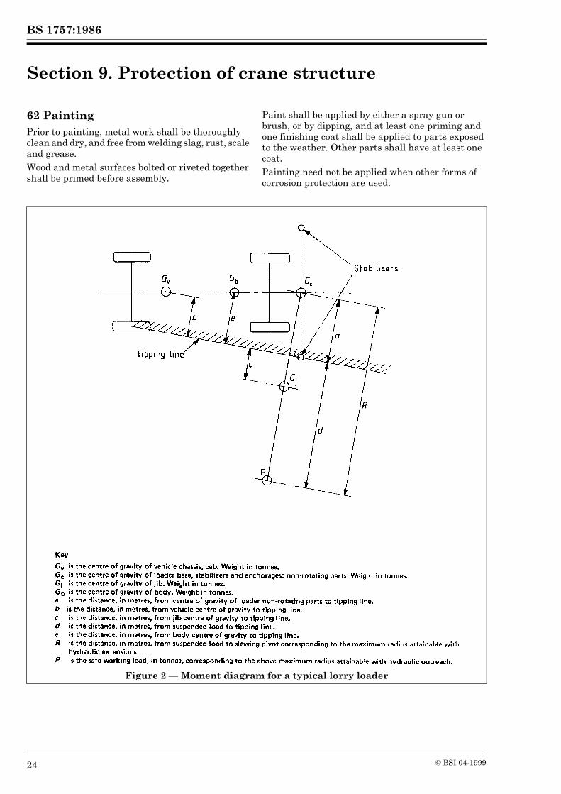
BS 1757:1986
24 © BSI 04-1999
Section 9. Protection of crane structure
62 PaintingPrior to painting, metal work shall be thoroughly clean and dry, and free from welding slag, rust, scale and grease.Wood and metal surfaces bolted or riveted together shall be primed before assembly.
Paint shall be applied by either a spray gun or brush, or by dipping, and at least one priming and one finishing coat shall be applied to parts exposed to the weather. Other parts shall have at least one coat.Painting need not be applied when other forms of corrosion protection are used.
Figure 2 — Moment diagram for a typical lorry loader
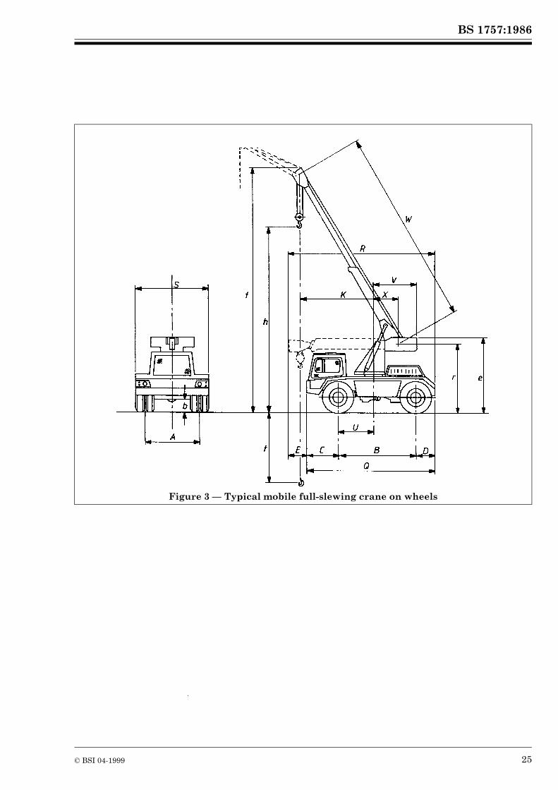
BS 1757:1986
© BSI 04-1999 25
Figure 3 — Typical mobile full-slewing crane on wheels

BS 1757:1986
26 © BSI 04-1999
Figure 4 — Typical truck mounted telescopic jib crane (with lattice fly jib shown inset) and outriggers
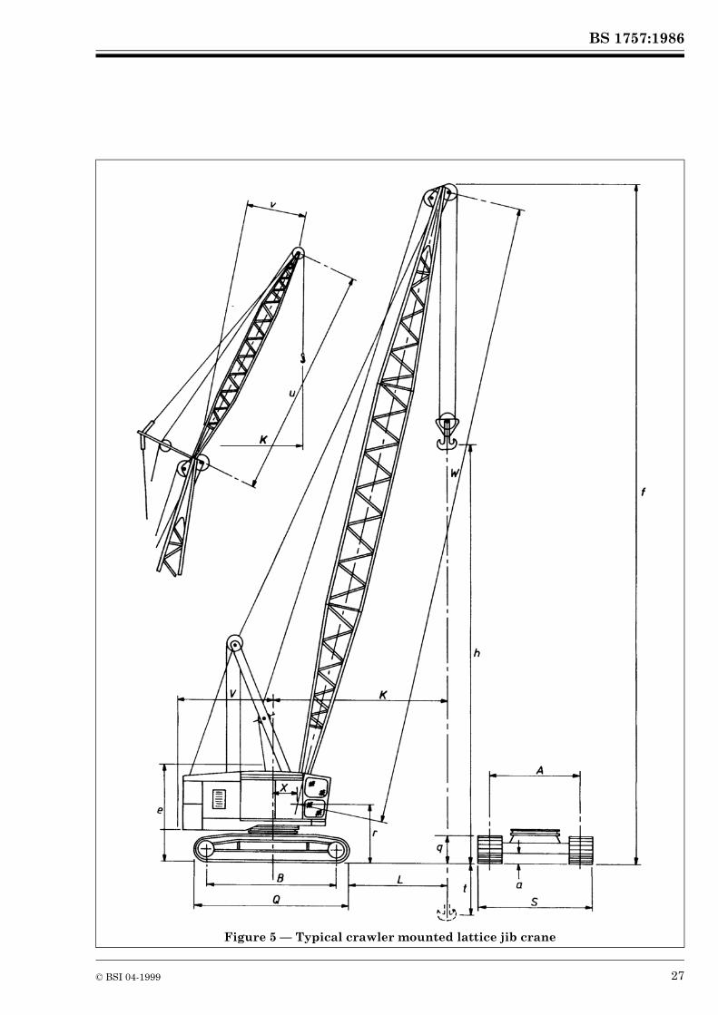
BS 1757:1986
© BSI 04-1999 27
Figure 5 — Typical crawler mounted lattice jib crane
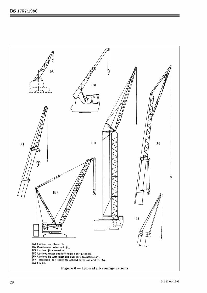
BS 1757:1986
28 © BSI 04-1999
Figure 6 — Typical jib configurations

BS 1757:1986
© BSI 04-1999 29
Figure 7 — Lorry loader: typical configurations
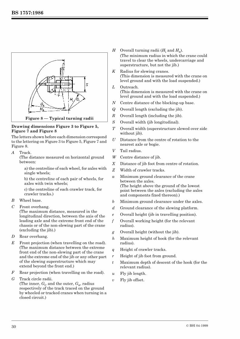
BS 1757:1986
30 © BSI 04-1999
Drawing dimensions Figure 3 to Figure 5, Figure 7 and Figure 8The letters shown before each dimension correspond to the lettering on Figure 3 to Figure 5, Figure 7 and Figure 8.
Figure 8 — Typical turning radii
A Track.(The distance measured on horizontal ground between:
a) the centreline of each wheel, for axles with single wheels;b) the centreline of each pair of wheels, for axles with twin wheels;c) the centreline of each crawler track, for crawler tracks.)
B Wheel base.
C Front overhang.(The maximum distance, measured in the longitudinal direction, between the axis of the leading axle and the extreme front end of the chassis or of the non-slewing part of the crane (excluding the jib).)
D Rear overhang.
E Front projection (when travelling on the road). (The maximum distance between the extreme front end of the non-slewing part of the crane and the extreme end of the jib or any other part of the slewing superstructure which may extend beyond the front end.)
F Rear projection (when travelling on the road).
G Track circle radii.(The inner, Gi, and the outer, Ga, radius respectively of the track traced on the ground by wheeled or tracked cranes when turning in a closed circuit.)
H Overall turning radii (Hi and Ha).(The minimum radius in which the crane could travel to clear the wheels, undercarriage and superstructure, but not the jib.)
K Radius for slewing cranes.(This dimension is measured with the crane on level ground and with the load suspended.)
L Outreach.(This dimension is measured with the crane on level ground and with the load suspended.)
N Centre distance of the blocking-up base.
Q Overall length (excluding the jib).
R Overall length (including the jib).
S Overall width (jib longitudinal).
T Overall width (superstructure slewed over side without jib).
U Distance from the centre of rotation to the nearest axle or bogie.
V Tail radius.
W Centre distance of jib.
X Distance of jib foot from centre of rotation.
Z Width of crawler tracks.
a Minimum ground clearance of the crane between the axles.(The height above the ground of the lowest point between the axles (excluding the axles and components fixed thereon).)
b Minimum ground clearance under the axles.
d Ground clearance of the slewing platform.
e Overall height (jib in travelling position).
f Overall working height (for the relevant radius).
g Overall height (without the jib).
h Maximum height of hook (for the relevant radius).
q Height of crawler tracks.
r Height of jib foot from ground.
t Maximum depth of descent of the hook (for the relevant radius).
u Fly jib length.
v Fly jib offset.

BS 1757:1986
© BSI 04-1999 31
Figure 9 — Typical lorry loader features
Figure 10 — Typical safe working load chart for a lorry loader

BS
1757:1986
32©
BS
I 04-1999
Figure 11 — Rating of typical crane at intermediate telescopic jib lengths (stepped duties)

BS
1757:1986
© B
SI 04-1999
33
Figure 12 — Rating of typical crane at intermediate telescopic jib lengths (interpolated duties)

BS 1757:1986
34 © BSI 04-1999
Appendix A Information recommended to be supplied with enquiry or order for cranes complying with BS 1757
A.1 Type of crane and dutyInformation should be provided that will enable the manufacturer to select the most suitable crane from his range to meet the purchaser’s requirements or, alternatively, to suggest a modified standard product or a specially designed machine. The information should include information regarding characteristics that are required, (see clause 1).A.2 Crane dutyThe following information should be provided regarding the crane duty.
a) General hook duties (classification A1). Size and type of loads, maximum height of lift and radius. Where loadings at intermediate radii are likely to be significant, details should also be given. For cranes with adjustable or telescopic jibs, these details should be given for all required jib lengths and radii.b) Bucket, grapple or magnet (classification A3). Nature of material to be handled and its mass density.c) Heavy duty (classification A4). Details of loads to be handled.d) Any other duty. Full details of any duty that may not be covered by clause 6.
NOTE 1 If it is desired to use an existing grab, full details of type of grab and gross weight of grab and contents should be stated.NOTE 2 If it is desired to use an existing magnet, full details of size, weight, voltage and current rating (cold) and lifting capacity should be given.A.3 Type of suspension and chassisState whether wheeled or crawler suspension is required and whether a road vehicle carrier is required.A.4 Site conditionsThe following information on site conditions should be provided.
a) Nature of ground over which the crane will have to operate, e.g. hard roads, temporary roads, hardstanding, grassland, or cross country; and whether the machine will have to travel on the public highway. Details of any physical or statutory limitations should be given.b) Any environmental limitations, e.g. proximity of potentially flammable or corrosive atmosphere.c) Climatic conditions including details of annual ambient temperature and humidity.d) Approximate altitude above sea level.e) Headroom available for working conditions.f) Height of any doorway or overhead beam under which the crane, with or without load, has to pass.g) Width of any doorway, road or passage-way, together with width of any branch road into which the crane has to turn and maximum clearance width for a full circle turn (if applicable).h) Where applicable details of any overhead lines, etc. that may restrict operation or movement.j) Particulars of any gradient, i.e. maximum slope and length the crane will be required to travel, the frequency of negotiation and whether loaded or unloaded.k) Any special limitations of axle load or ground pressure under wheels or crawlers.l) Any limitations on extension dimensions or ground pressure for outriggers.m) If possible a sketch should be given showing site conditions and clearances.
A.5 Lifting characteristicsThe following information on the lifting characteristics of the crane should be provided.
a) Whether auxiliary hoist is required in addition to main hoist, indicating required load rating.b) Any requirement or limitation regarding lifting speed.c) Range of lift of hook(s):
1) below ground level;2) above ground level.
d) Any unusual or exceptional duty.e) Details of alternative, extra, or unusual equipment or attachments, e.g. length and number of jib inserts, details of fly jib, etc.
BS 1757:1986
© BSI 04-1999 35
f) Details of any specific safety load limiting devices, etc. required (see A.9).A.6 CabThe following information on the cab should be provided.
a) Any special visual requirements, e.g. window to permit low vision below cab.b) Any special environmental conditions influencing cab design, e.g. air conditioning, special insulation in extreme climates, etc.c) Any special requirements for cab access.
A.7 Motive power unitState type of prime mover required, or, where appropriate, details of external electricity supply.A.8 Power transmission and control systemThe following information on power transmission and control systems should be provided.
a) Preference for mechanical, hydraulic, hydrodynamic, hydrostatic, air, electric operation of main transmission and control auxiliary system.b) Any special operator controls or instrumentation.
A.9 Travelling with loadState whether crane has to be capable of travelling with load.A.10 Safety devices and alarmsThe following information on safety devices and alarms should be provided.
a) Details of any safe load indicator, audible or visual alarm or cut-out specified by regulation or statute.b) Any other safety control equipment or device to be fitted.
A.11 Additional informationThe following information should also be provided.
a) Particulars of any further requirements or special conditions not included above, e.g. lighting, power load lowering, braking, etc.b) Any aspect of maintenance or servicing procedure that may require particular attention, e.g. any local limitations on servicing facilities or manpower.c) Any shipping limitations, e.g. weight, dimensions, method of slinging and available transport facilities.
A.12 Statutory requirementsGive details of any statutory requirements with which the crane has to comply (see Appendix D).
Appendix B Information to be supplied by manufacturer for cranes complying with BS 1757
B.1 GeneralThe information to be supplied in the tender by the manufacturer should include appropriate data from B.2 to B.5, together with such additional information necessary to satisfy the enquiry, and, where relevant, the recommendations of Appendix A.B.2 Types of crane and dutyThe following information should be provided.
a) Type and BS classification.b) Drawing and/or catalogue reference.c) For strut jib cranes, total length, number and assembly of sections.d) For telescopic cranes, jib length and number of extensions.e) Safe working loads at maximum and minimum radii, and such other significant radii as may be specified in enquiry, relevant to A.2 a). This information should be given for all jib lengths and configurations included in the tender, the main hoist, and, where fitted, auxiliary hoist.f) Details of rope reeving for main hoist (and where appropriate auxiliary hoist) for all relevant jib configurations and loads.

BS 1757:1986
36 © BSI 04-1999
g) Range of lift of hook(s) for all configurations above ground level.B.3 Machine characteristicsA schedule together with a drawing or diagram should be supplied giving physical dimensions, etc. of the crane, of which the following items are typical.
a) Overall length, width and height of crane both in shipping condition and assembled ready for operation.b) Shipping and operational weights, stating weight of heaviest piece to be handled during site assembly, and size and weight of any separate counterweight.c) Details and dimensions of crawlers for tracked machines.d) Number and disposition of axles for wheeled machines, including tyre details.e) Turning circle, with particular reference to the minimum distance between two parallel walls within which the crane chassis can be completely turned round in a single movement, both for “right lock” and “left lock”.f) The maximum gradient on which the crane may travel unloaded, and, where appropriate, loaded.g) Dimensions, including axle loads, and speeds for various gear ratios, in highway travelling condition (where applicable).h) Overall dimensions with outriggers extended.j) Dimensional position of extreme outer edge of tracks or outrigger jack pads relative to the centreline of the revolving superstructure.k) Maximum ground bearing pressure under extreme edge of crawler tracks or outrigger pads in extended position.l) Radius of tail swing of revolving superstructure.m) Position of jib foot pivot pin in relation to ground level and centre of rotation.
B.4 Mechanical and structural specificationInformation covering the following should be included.
a) Lifting speeds, and operating speeds for all motions, should be stated for all conditions and configurations.b) Material specifications for the jib and other main structural members.c) Type and rating of prime mover.d) Full specification of main and auxiliary transmission systems and controls including actuating medium, e.g. air, hydraulic, hydrostatic, electric, mechanical, etc.e) Specification of brakes and clutches, torque converters, hydraulic pumps, rams, etc.f) Description and layout diagram of operator’s controls.g) Details of cab equipment.h) Specification and lengths for all ropes supplied to cover the configurations relevant to B.2 e) and f).
B.5 Miscellaneous informationThe following miscellaneous information should be provided.
a) Details of safety devices, alarms, indicators, etc. and other safety control equipment.b) List of all tools and accessories supplied with the crane, indicating those which are “special” tools.c) Any unusual maintenance or servicing procedure unique to the crane.d) Such other information that will enable the enquirer to make a factual evaluation of the performance of the crane and its suitability for the requirements.e) Specification, type and size of any grab or magnet supplied with crane.
B.6 Erection and maintenance instructionsThe manufacturer shall supply full operational instructions, erection and dismantling instructions, a driver’s handbook, maintenance instructions, a parts manual and, where appropriate, a workshop manual.

BS 1757:1986
© BSI 04-1999 37
Appendix C List of British Standards for materials and equipment used in the manufacture of cranes
Crane detail BS No. Title
1. Permissible stresses 2573a Rules for the design of cranes
Part 1 Specification for classification, stress calculations and design criteria for structuresPart 2 Specification for classification, stress calculations and design of mechanisms
2. Materials
Castings, iron 2789 Specification for spheroidal graphite or nodular graphite cast iron
grey 1452 Specification for grey iron castingsmalleable blackheart 310 Blackheart malleable iron castingsmalleable whiteheart 309 Whiteheart malleable iron castingspearlitic malleable 3333 Pearlitic malleable iron castingsaustenitic 3468 Austenitic cast iron
Castings, steel 3100 Specification for steel castings for general engineering purposes
Keys and taper pins 46 Keys and keyways and taper pinsPart 1 Keys and keyways
Lighting fittings 4533 LuminairesLubricating nipples 1486 Lubricating nipplesRivet materials 4360 Specification for weldable structural steels
1109 Cold forged mild steel rivets for cold closingSteel, structural 4360 Specification for weldable structural steelsCotter pins 1574 Split cotter pins — metric and inch series
Gearing 436 Spur and helical gearsSteel bars for machined parts, shafts and axles
970 Specification for wrought steels for mechanical and allied engineering purposesPart 1 General inspection and testing procedures and specific requirements for carbon, carbon manganese, alloy and stainless steels
Steel plate, sheet and strip 1449 Steel plate, sheet and stripPart 1 Specification for carbon and carbon manganese plate, sheet and stripPart 2 Specification for stainless and heat resisting steel plate, sheet and strip
Springs, coil and spiral 24 Railway rolling stock materialPart 3B Helical and volute springs and spring steels
5216 Patented cold drawn carbon steel wire for mechanical springs1429 Specification for annealed steel wire for general engineering
springs1726 Guide to the design and specification of coil springs
a Referred to in the text.

BS 1757:1986
38 © BSI 04-1999
Crane detail BS No. Title
Structural steel sections 4 Structural steel sections
Part 1 Specification for hot-rolled sections
4848 Hot-rolled structural steel sections
Part 2 Hollow sections
Part 4 Equal and unequal angles
3. Structural details, etc.
Bolts, nuts 3692 ISO metric precision hexagon bolts, screws and nuts
1768 Unified precision hexagon bolts, screws and nuts (UNC and UNF threads). Normal series
4395a High strength friction grip bolts and associated nuts and washers for structural engineering
4604a The use of high strength friction grip bolts in structural steelwork. Metric series
3410 Metal washers for general engineering purposes
Rivets (dimensions) 4620 Rivets for general engineering purposes
641 Dimensions of small rivets for general purposes
Safety glass 5282a Road vehicle safety glass
Welding 5135 Specification for the process of arc welding of carbon and carbon manganese steels
4. Machinery and machinery details
Bearings, ball and cylindrical roller
292 Rolling bearings; ball bearings, cylindrical and spherical roller bearings
needle roller 5773 Metric needle roller bearings
taper roller 3134 Metric tapered roller bearings
Chains and chain wheels 228 Specification for short pitch transmission precision roller chains and chainwheels
4687 Specification for extended pitch precision roller chains and chainwheels
2947 Specification for steel roller chains types S and C, attachments and chainwheels for agricultural and similar machinery
Engines 5514a Specification for reciprocating internal combustion engines: performance
Keys and keyways 4235a Metric keys and keyways
Part 1 Parallel and taper keys
Part 2 Woodruff keys and keyways
Limits and fits 4500 ISO limits and fits
Lubricating nipples and adaptors
1486a Lubricating nipples
Part 1 Lubricating nipples and adaptors for use on machinery and vehicles
Part 2 Heavy duty lubricating nipples
Screw threads 3643 ISO metric screw threads
1580 Unified screw threadsa Referred to in the text.

BS 1757:1986
© BSI 04-1999 39
Crane detail BS No. Title
Splines and serrations 2059a Straight-sided splines and serrations
3550a Involute splines
Taper pins, solid and split 46 Keys and keyways and taper pins
Part 3 Solid and split taper pins
5. Electrical machinery and equipment
Cables 6708a Specification for trailing cables for mining purposes
6007a Specification for rubber-insulated cables for electric power and lighting
6231a Specification for PVC-insulated cables for switchgear and controlgear wiring
6004a Specification for PVC-insulated cables (non-armoured) for electric power and lighting
6116a Elastomer-insulated flexible trailing cables for quarries and miscellaneous mines
Conduit 31a Steel conduit and fittings for electrical wiring
4568a Steel conduit and fittings with metric threads of ISO form for electrical installations
Switchgear controllers and resistors
587 Motor starters and controllers
5486a Low-voltage switchgear and controlgear assemblies
Head lamps 4533 Luminaires
Section 102.8 Specification for handlamps
5420a Specification for degrees of protection of enclosures of switchgear and controlgear for voltages up to and including 1 000 V a.c. and 1 200 V d.c.
Electrical equipment of machine tools
2771 Electrical equipment of machine tools. General purpose and mass production machines and their electronic equipment
Motors 5000a Rotating electrical machines of particular types or for particular applications
Part 99 Machines for miscellaneous applications
173a Method of specifying the performance of rotating electrical machines for use on rail and road vehicles
4999a General requirements for rotating electrical machines
Radio interference 800a Specification for radio interference limits and measurements for household appliances, portable tools and other electrical equipment causing similar types of interference
833a Radio-interference limits and measurements for the electrical ignition systems of internal combustion engines
Transformers 3535 Safety isolating transformers for industrial and domestic purposes
Earthing 4444a Guide to electrical earth monitoring
6. Pneumatic equipment 21 Specification for pipe threads for tubes and fittings where pressure-tight joints are made on the threads (metric dimensions)
2779 Pipe threads where pressure-tight joints are not made on the threads
a Referred to in the text.

BS 1757:1986
40 © BSI 04-1999
Appendix D Legislation that may affect mobile cranes in the United Kingdom1. Health & Safety at Work etc. Act 1974.2. Factories Act 1961.3. The Chains, Ropes & Lifting Tackle (Register) Order 1938, S.R & O. No. 599, 1938.4. The Lifting Machines (Particulars of Examinations) Order 1963. S.I. 1963 No. 1382.5. Certificate of Exemption No. 1. Annealing. Factory Form 661. 1938.6. Docks Regulations, 1925. S.R. & O. No. 231 (Regulations 18, 19, 20 & 46 only).7. Docks Regulations, 1934. S.R. & O. No. 279.8. Docks Regulations, 1934. Certificate of Exemption No. 1. Annealing. Factory Form 1950.9. Ship Building & Ship Repairing Regulations, S.I. 1960 No. 1932.10. The Construction (Lifting Operations) Regulations S.I. 1961 No. 1581.11. Certificate of Exemption No. 6 (General) Telescopic Jib Cranes.12. The Construction (Lifting Operations) Certificates Order, S.I. 1962 No. 227.13. The Construction (Lifting Operations) Certificates (Amendment) Order, S.I. 1964 No. 531.14. The Construction (Lifting Operations) Reports Order, S.I. 1962 No. 225.15. The Construction (Lifting Operations) Prescribed Particulars Order, S.I. 1962 No. 226.16. The Construction (Lifting Operations) Prescribed Particulars (Amendment) Order, S.I. 1962 No. 1747.17. The Construction (General Provisions) Regulations S.I. 1961 No. 1580.18. The Construction (Working Places) Regulations, S.I. 1966 No. 94.
Crane detail BS No. Title
3256a Small fusion-welded air reservoirs for road and railway vehicles
5169a Fusion-welded steel air receivers
7. Lifting equipment
Hooks 2903a Specification for higher tensile steel hooks for chains, slings, blocks and general engineering purposes
3017a Mild steel forged ramshorn hooks
Shackles 3032a Higher tensile steel shackles
3551a Alloy steel shackles
Wire ropes 302 Wire ropes for cranes, excavators and general engineering purposes
Connections 461a Bordeaux connections
462 Specification for wire rope grips
463a Sockets for wire ropes
464a Thimbles for wire ropes
5281 Ferrule secured eye terminations for wire ropes8. Codes of practice 5304a Code of practice for safeguarding of machinery
CP 1011a Maintenance of electric motor control gear
CP 1016a The use of semiconductor devices
CP 1017a Distribution of electricity on construction and building sites
CP 3010a Safe use of cranes (mobile cranes, tower cranes and derrick cranes)
9. Cabin design 5538a Specification for minimum operator space envelope forearth-moving machinery
a Referred to in the text.

BS 1757:1986
© BSI 04-1999 41
19. The Electricity (Factories Act) Special Regulations, 1908 & 1944, S.R. & O. 1908, No. 1312, as amended by S.R. & O. 1944 No. 739.20. The Factories Act (Northern Ireland) 1965.21. The Shipbuilding and Ship Repairing Regulations (Northern Ireland) 1960.22. The Construction (Lifting Operations) Regulations (Northern Ireland) 1963.23. The Docks Regulations (Northern Ireland) 1934.24. Road Traffic Act 1962.Cranes for use in coal and metalifferous mines and quarries are subject to:
Mines and Quarries Act 1954Mines and Quarries (Tips) Act, 1969Coal and Other Mines (Electricity) Regulations, S.I. 1956 No. 1766Miscellaneous Mines (Electricity) Regulations, S.I. 1956 No. 1779Quarries (Electricity) Regulations, S.I. 1956 No. 1781.
Copies of these documents may be obtained from:HM Stationery Office49 High HolbornLondonWC1V 6HB
References. Table 8 indicates which section of appropriate statutory regulations may apply to certain clauses in the specification. It should not be assumed that the list of references is complete.
Table 8 — References to statutory regulations
Clause Subject Regulations
12 Wire ropes Docks Regulations regarding appropriate ratios14 Lifting hooks Regulation 36 of the Construction (Lifting Operations)
Regulations, 196125 Guarding Part 11, Factories Act, 1961 and Regulations 42 and 43 of
the Construction (General Provisions) Regulations, 196128 Crane driver’s station Regulation 147 of the Construction (Lifting Operations)
Regulations, 196144 Air receivers Section 36 of the Factories Act, 1961 Special Regulations,
S.R. & O, No. 1312, 1908 and 194433 Protective gear Electricity (Factories Act) Special Regulations
S.R. & O. No. 1312, 1908 and 194436 Trailing cables (application to
BS 6708 and BS 6116)Coal and other Mines Electricity Regulations, 1956 or the Miscellaneous Mines Electricity Regulations, 1956
40 Radio interference Wireless Telegraphy Act, 194949 and 50
Radius/jib angle indicators and safe load indicators
Section 27(4) of the Factories Act, 1961 and Regulations 29 and 30 of the Construction (Lifting Operations) Regulations, 1961
60 Certifications Relevant information to be included is specified in the Factories Act, 1961 and Regulations made thereunder

BS 1757:1986
42 © BSI 04-1999
Appendix E The calculation of stability of lorry loaders (see 59.5.4.2)E.1 To enable stability of a lorry loader to be verified by calculation the following information will be required:
a) axle loads of the vehicle without the loader;b) the masses and position of the centre of gravity of any added parts such as stabilizers, hydraulic oil tanks or PTO and pump;c) the mass and position of any non-rotating parts of the loader;d) the mass of and radius of the centre of gravity of the extended jib system.
E.2 Prepare a moment diagram for the lorry loader including contact points with the ground, the position of the fully deployed stabilizers and the loader pivot point and the tipping line.Figure 2 shows a moment diagram for a typical lorry loader and Figure 14 shows typical tipping lines.E.3 Verify the stability of the lorry loader by calculating moments about the tipping line to show that these meet the requirements of 59.5.4.2, i.e. for the typical example in Figure 2:
(Gv × b) + (Gb × e) + (Gc × a) $ 1.4 × [(Gj × c) + (P × d)]

BS 1757:1986
© BSI 04-1999 43
Appendix F Typical form of test certificate
Certificate of test for a mobile crane or lorry loaderNOTE A test certificate may, in certain statutory circumstances, also be required in a prescribed form, e.g. if the operation of a lorry loader is covered by the Factories or the Construction (Lifting Operation) Regulations 1961.
NOTE 1 For lorry loaders a certificate of test should be issued before an assembled loader and lorry are taken into service:a) for a new lorry and new loader;b) for a new lorry and used loader;c) for a used lorry and new loader;d) for a used lorry and used loader;e) for any repositioning of a loader or a lorry.
NOTE 2 It is recommended that a certificate of test should be issued for all cranes lorry loaders:a) following substantial alteration or repair;b) at periods of not more than 4 years.
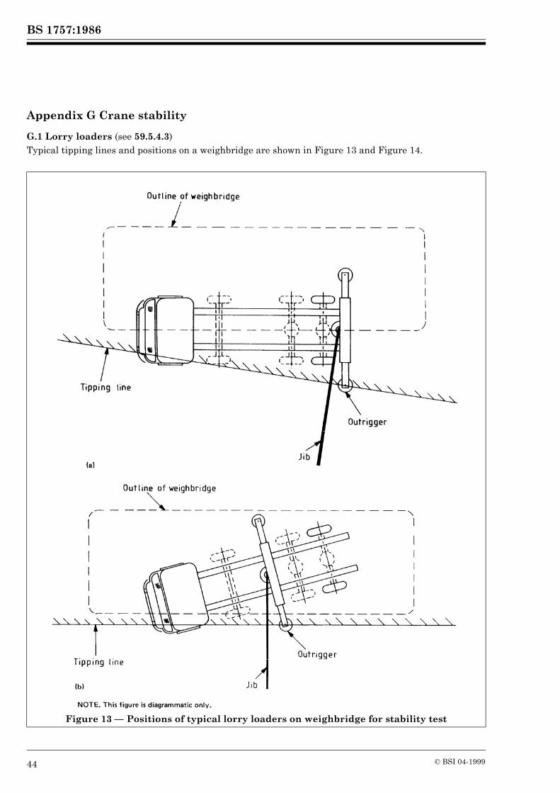
BS 1757:1986
44 © BSI 04-1999
Appendix G Crane stability
G.1 Lorry loaders (see 59.5.4.3)Typical tipping lines and positions on a weighbridge are shown in Figure 13 and Figure 14.
Figure 13 — Positions of typical lorry loaders on weighbridge for stability test

BS 1757:1986
© BSI 04-1999 45
Figure 13 — Positions of typical lorry loaders on weighbridge for stability test (concluded)
Figure 14 — Typical tipping lines for lorry loaders

BS 1757:1986
46 © BSI 04-1999
Figure 14 — Typical tipping lines for lorry loaders (concluded)
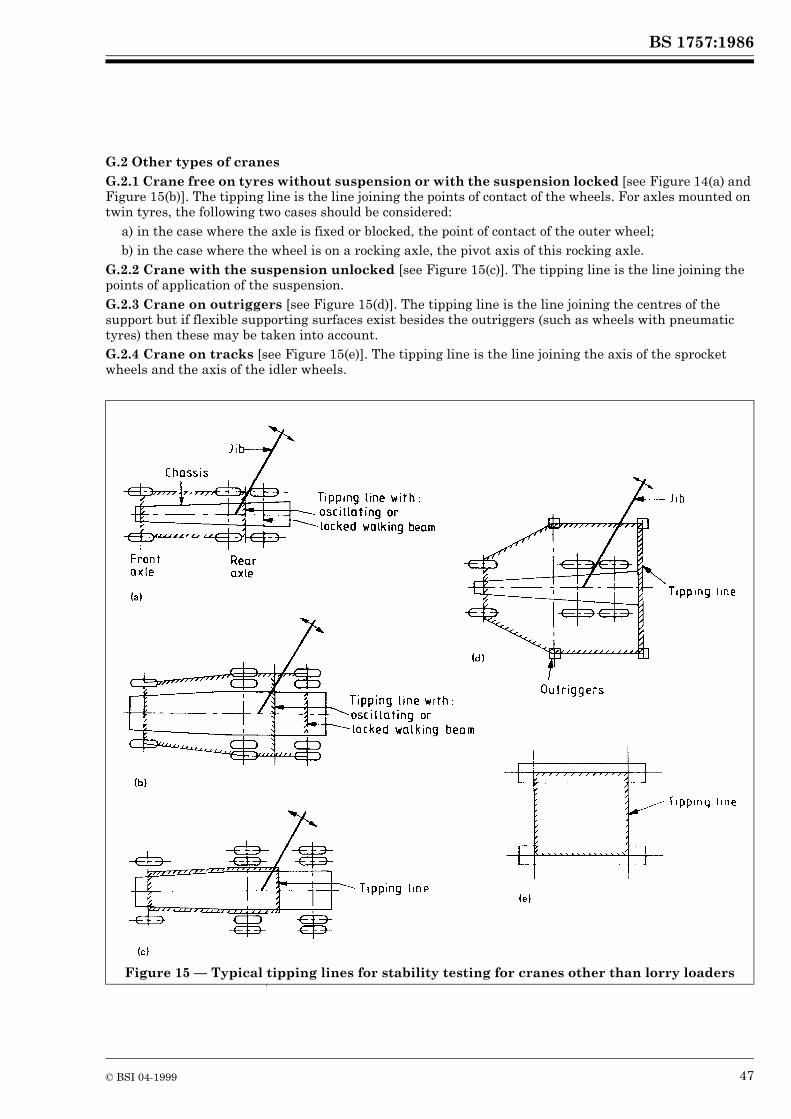
BS 1757:1986
© BSI 04-1999 47
G.2 Other types of cranesG.2.1 Crane free on tyres without suspension or with the suspension locked [see Figure 14(a) and Figure 15(b)]. The tipping line is the line joining the points of contact of the wheels. For axles mounted on twin tyres, the following two cases should be considered:
a) in the case where the axle is fixed or blocked, the point of contact of the outer wheel;b) in the case where the wheel is on a rocking axle, the pivot axis of this rocking axle.
G.2.2 Crane with the suspension unlocked [see Figure 15(c)]. The tipping line is the line joining the points of application of the suspension.G.2.3 Crane on outriggers [see Figure 15(d)]. The tipping line is the line joining the centres of the support but if flexible supporting surfaces exist besides the outriggers (such as wheels with pneumatic tyres) then these may be taken into account.G.2.4 Crane on tracks [see Figure 15(e)]. The tipping line is the line joining the axis of the sprocket wheels and the axis of the idler wheels.
Figure 15 — Typical tipping lines for stability testing for cranes other than lorry loaders

48 blank

BS 1757:1986
© BSI 04-1999
Publications referred to
BS 31, Steel conduit and fittings for electrical wiring. BS 461, Bordeaux connections. BS 462, Specification for wire rope grips. BS 463, Sockets for wire ropes. BS 463-2, Metric units. BS 464, Thimbles for wire ropes. BS 800, Specification for radio interference limits and measurements for household appliances, portable tools and other electrical equipment causing similar types of interference. BS 833, Radio interference limits and measurements for the electrical ignition systems of internal combustion engines. BS 1486, Lubricating nipples. BS 2059, Straight-sided splines and serrations. BS 2573, Rules for the design of cranes. BS 2903, Specification for higher tensile steel hooks for chains, slings, blocks and general engineering purposes. BS 3017, Mild steel forged ramshorn hooks. BS 3032, Higher tensile steel shackles. BS 3256, Small fusion-welded air reservoirs for road and railway vehicles. BS 3550, Involute splines. BS 3551, Alloy steel shackles. BS 4235, Metric keys and keyways. BS 4395, High strength friction grip bolts and associated nuts and washers for structural engineering. BS 4395-1, General grade. BS 4444, Guide to electrical earth monitoring. BS 4568, Steel conduit and fittings with metric threads of ISO form for electrical installations. BS 4575, Guide for application of fluid power equipment to transmission and control systems. BS 4604, The use of high strength friction grip bolts in structural steelwork. Metric series. BS 4604-1, General grade. BS 4999, General requirements for rotating electrical machines. BS 5000, Rotating electrical machines of particular types or for particular applications. BS 5169, Fusion-welded steel air receivers. BS 5282, Road vehicle safety glass. BS 5304, Code of practice for safeguarding of machinery. BS 5420, Specification for degrees of protection of enclosures of switchgear and controlgear for voltages up to and including 1 000 V a.c. and 1 200 V d.c.. BS 5486, Low-voltage switchgear and controlgear assemblies. BS 5486-1, Specification for type-tested and partially type-tested assemblies (general requirements). BS 5514, Specification for reciprocating internal combustion engines: performance. BS 5538, Specification for minimum operator space envelope for earth-moving machinery. BS 6004, Specification for PVC-insulated cables (non-armoured) for electric power and lighting. BS 6007, Specification for rubber-insulated cables for electric power and lighting. BS 6116, Elastomer-insulated flexible trailing cables for quarries and miscellaneous mines. BS 6231, Specification for PVC-insulated cables for switchgear and controlgear wiring. BS 6708, Specification for trailing cables for mining purposes. CP 1011, Maintenance of electric motor control gear. CP 1016, The use of semiconductor devices. CP 1017, Distribution of electricity on construction and building sites. CP 3010, Safe use of cranes (mobile cranes, tower cranes and derrick cranes).

BS 1757:1986
BSI389 Chiswick High RoadLondonW4 4AL
BSI — British Standards InstitutionBSI is the independent national body responsible for preparing British Standards. It presents the UK view on standards in Europe and at the international level. It is incorporated by Royal Charter.
Revisions
British Standards are updated by amendment or revision. Users of British Standards should make sure that they possess the latest amendments or editions.
It is the constant aim of BSI to improve the quality of our products and services. We would be grateful if anyone finding an inaccuracy or ambiguity while using this British Standard would inform the Secretary of the technical committee responsible, the identity of which can be found on the inside front cover. Tel: 020 8996 9000. Fax: 020 8996 7400.
BSI offers members an individual updating service called PLUS which ensures that subscribers automatically receive the latest editions of standards.
Buying standards
Orders for all BSI, international and foreign standards publications should be addressed to Customer Services. Tel: 020 8996 9001. Fax: 020 8996 7001.
In response to orders for international standards, it is BSI policy to supply the BSI implementation of those that have been published as British Standards, unless otherwise requested.
Information on standards
BSI provides a wide range of information on national, European and international standards through its Library and its Technical Help to Exporters Service. Various BSI electronic information services are also available which give details on all its products and services. Contact the Information Centre. Tel: 020 8996 7111. Fax: 020 8996 7048.
Subscribing members of BSI are kept up to date with standards developments and receive substantial discounts on the purchase price of standards. For details of these and other benefits contact Membership Administration. Tel: 020 8996 7002. Fax: 020 8996 7001.
Copyright
Copyright subsists in all BSI publications. BSI also holds the copyright, in the UK, of the publications of the internationalstandardization bodies. Except as permitted under the Copyright, Designs and Patents Act 1988 no extract may be reproduced, stored in a retrieval system or transmitted in any form or by any means – electronic, photocopying, recording or otherwise – without prior written permission from BSI.
This does not preclude the free use, in the course of implementing the standard, of necessary details such as symbols, and size, type or grade designations. If these details are to be used for any other purpose than implementation then the prior written permission of BSI must be obtained.
If permission is granted, the terms may include royalty payments or a licensing agreement. Details and advice can be obtained from the Copyright Manager. Tel: 020 8996 7070.